WO2017131285A1 - Container network management system and container networking method - Google Patents
Container network management system and container networking methodDownload PDFInfo
- Publication number
- WO2017131285A1 WO2017131285A1PCT/KR2016/002924KR2016002924WWO2017131285A1WO 2017131285 A1WO2017131285 A1WO 2017131285A1KR 2016002924 WKR2016002924 WKR 2016002924WWO 2017131285 A1WO2017131285 A1WO 2017131285A1
- Authority
- WO
- WIPO (PCT)
- Prior art keywords
- container
- packet
- bridge
- network
- legacy
- Prior art date
- Legal status (The legal status is an assumption and is not a legal conclusion. Google has not performed a legal analysis and makes no representation as to the accuracy of the status listed.)
- Ceased
Links
Images


Classifications
- H—ELECTRICITY
- H04—ELECTRIC COMMUNICATION TECHNIQUE
- H04L—TRANSMISSION OF DIGITAL INFORMATION, e.g. TELEGRAPHIC COMMUNICATION
- H04L12/00—Data switching networks
- H04L12/50—Circuit switching systems, i.e. systems in which the path is physically permanent during the communication
Definitions
- the present inventionrelates to a software defined network (SDN) -based container network management system and a container networking method of a container network, to enable L2 / L3 networks between containers, to reduce unnecessary multicast and broadcast traffic,
- SDNsoftware defined network
- the present inventionrelates to a management system and a networking method for enabling flexible network operation and enabling packet flow between a legacy network and an SDN network.
- SDNis a basic network infrastructure abstracted from the application, logically centralized network intelligence, and separated from the control plane and data plane.
- Open flowseparates high speed packet delivery and high level routing decision functions.
- the packet forwarding planeis still involved in the switch stage, while high-level routing decisions are involved in separate controllers, which communicate through open flow protocols.
- Lightweight containerswhich are different from existing virtual machines, are used instead of virtual machines.
- Containersdo not have network management, and all containers are in the same L2 domain. This makes it difficult to manage the policy of the network and makes it difficult to manage network functions by services.
- management of frontend / backend networks for each serviceis required. Only the front end is accessible from the public network, and the rest of the computing work is done only on the back end network, which is private.
- Containersdo not have such a network management mechanism, which makes it difficult to manage the network.
- Non-Patent Document 1OpenFlow Switch Specification version 1.4.0 (Wire Protocol 0x05), October 14, 2013 [https://www.opennetworking.org/images/stories/downloads/sdn-resources/onf-specifications/openflow/openflow -spec-v1.4.0.pdf]
- Non-Patent Document 2Software-Defined Networking: The New Norm for Netwrks, ONF White Paper, April 13, 2012 [https://www.opennetworking.org/images/stories/downloads/sdn-resources/white-papers/wp -sdn-newnorm.pdf]
- Non-Patent Document 3ETSI GS NFV 002 v1.1.1 (2013-10)
- An object of the present inventionis to provide a network environment for enabling container management of a container, to provide a network environment for enabling L2 / L3 networks, and to enable a private network separate from an external network under container operation. To provide.
- Another object of the present inventionis to provide a system and method for supporting a legacy network in an SDN-based container network.
- the container network management systemincludes a real network interface connected to a legacy network; A software defined network (SDN) -based virtual switch that exchanges packets with a legacy network through the real network interface; A host controller generating the virtual switch; A container bridge generated by the host controller and virtually network coupled with the virtual switch through a bridge-switch network interface (NI), the container bridge having a bridge identifier identifying itself; A database for storing network subnet information and gateway information using the actual network interface as a gateway based on the bridge identifier as bridge net information; And a first host generated by the host controller, assigned with a unique IP address based on the bridge net information, and having a plurality of containers virtually network coupled to the container bridge.
- SDNsoftware defined network
- NIbridge-switch network interface
- the hostcomprises a real network interface connected to a legacy network; A software defined network (SDN) based virtual switch controlled by an external controller to exchange packets with a legacy network through the actual network interface; A host controller generating the virtual switch; A container bridge generated by the host controller and virtually network coupled with the virtual switch through a bridge-switch network interface (NI), the container bridge having a bridge identifier identifying itself; A database for storing network subnet information and gateway information using the actual network interface as a gateway based on the bridge identifier as bridge net information; And a plurality of containers generated by the host controller, assigned a unique IP address based on the bridge net information, and virtually network-coupled to the container bridge.
- SDNsoftware defined network
- NIbridge-switch network interface
- a container networking method of a container networkincludes: creating a container and creating a virtual switch based on a software defined network (SDN) in a host connected to a legacy network through an actual network interface; Networking the virtual switch with the real network interface;
- SDNsoftware defined network
- the hostreceives a container container bridge creation request including a bridge identifier for distinguishing a network environment, gateway information using the virtual switch as a gateway, and network subnet information, generating a container bridge; Network coupling the container bridge and the virtual switch such that packets having all the same domain identifiers pass between the container bridge and the virtual switch;
- the hostreceives a container creation request including a first container identifier having a bridge identifier as a key and a first same domain identifier, generating a first container having the first container identifier; Assigning an IP address to the first container based on network subnet information associated with the bridge identifier; And a bridge of the container bridge coupled to the container such that the container bridge and the first container are network
- the present inventionit is possible to manage a network of containers in an SDN-based container network, to provide L2 / L3 networking between containers, to be separated into a public network and a private network in which a service is operated, and to communicate with a legacy network.
- Thisallows existing legacy network equipment to be used as is.
- 1is a structural diagram of an SDN network system
- FIG. 2is a block diagram of a controller of the network system of FIG. 1;
- FIG. 3is a block diagram of a switch of the network system of FIG.
- 4is an operation table indicating a field table of a flow entry and an operation type according to the flow entry;
- 5is a field table of a group and a meter table
- FIG. 6is a block diagram of a network system including an integrated routing system according to an embodiment of the present invention.
- FIG. 7is a block diagram of a virtualized network of the network system of FIG.
- FIG. 8is a block diagram of an SDN controller according to another embodiment of the present invention.
- FIG. 9is a block diagram of a legacy routing container according to an embodiment of the present invention.
- FIG. 10is a flowchart illustrating a method of determining legacy routing for a flow of the controller of FIG. 6.
- FIG. 11is a signal flow diagram according to an integrated routing method according to an embodiment of the present invention.
- FIG. 14is a structural diagram showing a container network management system according to an embodiment of the present invention.
- FIG. 15is a block diagram of a host mainly showing the internal structure of the host of FIG.
- 16is a flow chart of a container creation method according to an embodiment of the present invention.
- FIG. 17is a structural diagram showing another host internal structure of FIG. 14;
- FIG. 18is a structural diagram briefly showing FIG. 14;
- FIG. 19is a network structure diagram of FIG. 18 converted to a legacy virtual router
- 20 through 23are signal flow diagrams for packet flows from one container to another.
- first and secondmay be used to describe various components, but the components should not be limited by the terms. The terms are used only for the purpose of distinguishing one component from another.
- the first componentmay be referred to as the second component, and similarly, the second component may also be referred to as the first component.
- a componentWhen a component is referred to as being “connected” or “connected” to another component, it may be directly connected to or connected to that other component, but it may be understood that other components may be present in between. Should be. On the other hand, when a component is said to be “directly connected” or “directly connected” to another component, it should be understood that there is no other component in between.
- first component and the second component on the networkare connected or connected, it means that data can be exchanged between the first component and the second component by wire or wirelessly.
- moduleand “unit” for the components used in the following description are merely given in consideration of ease of preparation of the present specification, and do not give particular meanings or roles by themselves. Therefore, the “module” and “unit” may be used interchangeably.
- Such componentsmay be configured by combining two or more components into one component, or by dividing one or more components into two or more components as necessary when implemented in an actual application.
- the same reference numeralsare given to the same or similar components throughout the drawings, and detailed descriptions of the components having the same reference numerals may be omitted by replacing the descriptions of the aforementioned components.
- SDNis a separate concept from the data plane that carries packets and the control plane that controls the flow of packets.
- the network equipmentasks the SDN control software (controller) where to forward the packet and reflects the result to determine the path and method of transmitting the packet.
- SDNis a theoretical concept, and Openflow has emerged for practical application.
- OpenFlowis a standard interface established to implement SDN. Openflow is composed of an openflow controller and an openflow switch to control flow information to determine the delivery path and method of the packet. Throughout this specification, openflow and SDN may be used interchangeably or in the same sense.
- a flowmay refer to a packet flow of a specific path according to a combination of a series of packets or multiple flow entries of multiple switches that share a value of at least one header field from one switch perspective.
- Openflow networkscan perform path control, failover, load balancing and optimization on a flow-by-flow basis.
- Flowmay mean the packet itself to be processed by the switch.
- Flowmay also include a packet to be processed by the corresponding switch and metadata (an inlet port entered by the packet, an inlet port of the other switch when the packet comes in from another switch, etc.).
- the “flow processing information”is information for processing a packet introduced from a switch, and may mean information necessary for modifying a packet or metadata of a packet and / or a specific network interface (port) through which the packet is leaked.
- the flow processing informationmay be the same as the content of the flow entry of the flow table or the content to be applied to the flow entry, and may mean the flow entry itself.
- Flow processingmay mean that the switch processes a packet or a flow based on the flow processing information.
- FIG. 1is a block diagram of an SDN network system
- FIG. 2is a block diagram of a controller of the network system of FIG. 1
- FIG. 3is a block diagram of a switch of the network system of FIG.
- An operation tableshowing the operation type according to the field table and the flow entry
- FIG. 5is a field table of the group and meter table.
- an SDN network systemmay include a controller 10, a plurality of switches 20, and a plurality of network devices 30.
- the network device 30may include a user terminal device for exchanging data or information, or a physical device or a virtual device for performing a specific function. From a hardware point of view, the network device 30 may be a PC, a client terminal, a server, a workstation, a supercomputer, a mobile communication terminal, a smartphone, a smart pad, or the like. Network device 30 may also be a virtual machine (VM) created on a physical device.
- VMvirtual machine
- the network device 30may be referred to as a network function that performs various functions on the network.
- Network featuresinclude anti-DDoS, intrusion detection / blocking (IDS / IPS), integrated security services, virtual private network services, antivirus, antispam, security services, access management services, firewalls, load balancing, QoS, video optimization, etc. It may include.
- This network functioncan be virtualized.
- a virtualized network functionis the Network Function Virtualization (NFV) defined in the NFV white paper (see Non-Patent Document 3) issued by the ETSI (European Telecommunication Standards Association).
- Network functioncan be used interchangeably with network function virtualization (NFV) herein.
- NFVdynamically creates the necessary L4-7 service connections per tenant to provide the necessary network functions, or in the case of DDoS attacks, quickly provides the necessary firewall, IPS, and DPI features through a series of service chaining. Can be.
- NFVcan easily turn on or off firewalls or IDS / IPS and automatically provision them. NFV can also reduce the need for over-provisioning.
- the controller 10is a kind of command computer that controls the SDN system, and can perform various and complex functions such as routing, policy declaration, security check, and the like.
- the controller 10may define a flow of packets occurring in the plurality of switches 20 of the lower layer.
- the controller 10may calculate a path (data path) for the flow to pass through by referring to the network topology and the like for the flow allowed by the network policy, and then allow the entry of the flow to be set in the switch on the path.
- the controller 10may communicate with the switch 20 using a specific protocol, such as an openflow protocol.
- the communication channel of the controller 10 and the switch 20may be encrypted by SSL.
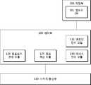
- the controller 10may include a switch communication unit 110, a control unit 100, and a storage unit 190 communicating with the switch 20.
- the storage unit 190may store a program for processing and controlling the controller 100.
- the storage unit 190may perform a function for temporarily storing input or output data (packets, messages, etc.).
- the storage unit 190may include an entry database (DB) 191 that stores flow entries.
- DBentry database
- the controller 100may control the overall operations of the controller 10 by controlling the operations of the respective units.
- the controller 100may include a topology management module 120, a path calculation module 125, an entry management module 135, and a message management module 130. Each module may be configured in hardware in the controller 100, or may be configured in software separate from the controller 100.
- the topology management module 120may construct and manage network topology information based on a connection relationship of the switches 20 collected through the switch communication unit 110.
- the network topology informationmay include a topology between switches and a topology of network devices connected to each switch.
- the topology informationmay be stored in the storage 190.
- the path calculation module 125may obtain a data path of a packet received through the switch communication unit 110 and an action string to be executed in the switch on the data path based on the network topology information constructed by the topology management module 120.
- the entry management module 135may register with the entry DB 191 as an entry such as a flow table, a group table, and a meter table based on a result calculated by the route calculation module 125, a policy such as QoS, a user indication, and the like. Can be.
- the entry management module 135may allow an entry of each table to be registered in advance in the switch 20, or may be responsive to a request for adding or updating an entry from the switch 20.
- the entry management module 135may change or delete an entry of the entry DB 191 as necessary or by an entry destruction message of the switch 10.
- the message management module 130may interpret a message received through the switch communication unit 110 or generate a controller-switch message to be described later transmitted to the switch through the switch communication unit 110.
- the state change messagewhich is one of the controller-switch messages, may be generated based on an entry generated by the entry management module 135 or an entry stored in the entry DB 191.
- the switch 20may be a physical switch or a virtual switch that supports the OpenFlow protocol.
- the switch 20may process the received packet to relay the flow between the network devices 30.
- the switch 20may be provided with one flow table or multiple flow tables for pipeline processing described in Non-Patent Document 1.
- the flow tablemay include a flow entry that defines a rule of how to process the flow of the network device 30.
- the switch 20may be divided into a core switch between an ingress switch and an egress switch and an edge switch of a flow according to a combination of multiple switches.
- the switch 20includes a port unit 205 for communicating with another switch and / or a network device, a controller communication unit 210 for communicating with the controller 10, a switch control unit 200, and a storage unit ( 290).
- the port portion 205may have a plurality of pairs of ports connected to a switch or a network device.
- the pair of portsmay be implemented as one port.
- the storage unit 290may store a program for processing and controlling the switch control unit 200.
- the storage unit 290may perform a function for temporarily storing input or output data (packets, messages, etc.).
- the storage unit 290may include a table 291, such as a flow table, a group table, and a meter table.
- the table 230 or entries in the tablemay be added, modified, or deleted based on the message of the controller 10. The table entry can be discarded by itself by the switch 20.
- Flow tablescan be composed of multiple flow tables to handle the pipeline of OpenFlow.
- a flow entry of a flow tableincludes match fields describing the conditions (control rules) matching packets, priority, counters updated when there is a match, Instructions, which are a set of various actions that occur when a packet is matched in a flow entry, timeouts describing the time to be discarded from the switch, and an opaque type selected by the controller. And may be used to filter flow statistics, flow changes, and flow deletions, and may include tuples such as cookies that are not used in packet processing.
- Instructionscan alter pipeline processing, such as forwarding packets to another flow table. Instructions can also include a set of actions that add an action to an action set, or a list of actions to apply directly to a packet.
- An actionmay mean an operation of modifying a packet such as transmitting a packet to a specific port or decreasing a TTL field.
- An actionmay belong to an action bucket associated with a group entry or part of a set of instructions associated with a flow entry.
- An action setmeans a set of accumulated actions indicated in each table. An action set can be performed when no table matches. 5 illustrates various packet processing by flow entries.
- Pipelinemeans a series of packet processing between packet and flow table.
- the switch 20searches for a flow entry matching the packet in the order of high priority of the first flow table. If a match is found, the instruction of the entry is executed. Instructions are executed immediately after a match (apply-action), clear-action (write-action), metadata modification (write-metadata), specified There are goto-tables that move packets with metadata into tables. If there is no flow entry matching the packet, the packet may be dropped or sent to the controller 10 in a packet-in message according to the table setting.
- the group tablemay include group entries.
- the group tablemay be indicated by the flow entry to suggest additional forwarding methods.
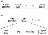
- a group entry of a group tablemay include the following fields.
- a group identifierthat identifies the group entry, a group type that specifies a rule as to whether to perform some or all of the action buckets defined in the group entry, a counter of the flow entry Counters for statistics, and action buckets, which are a set of actions associated with parameters defined for a group.
- the meter tableconsists of meter entries and defines per-flow meters. Per flow meter can allow openflow to apply various QoS operations.
- a meteris a kind of switch element that can measure and control the rate of packets.
- a meter tableincludes a meter identifier for identifying a meter, meter bands indicating a speed designated in a band and a packet operation method, and a packet. It consists of counter fields that are updated when running on the meter.
- Meter bandsare band types that indicate how packets are processed, the rate used to select the meter band by the meter, and counters that are updated when packets are processed by the meter band. ), And fields such as type specific arguments, which are bad types with optional arguments.
- the switch controller 200may typically control the operations of the units to control the overall operation of the switch 20.
- the switch controller 200may include a table management module 240, a flow search module 220, a flow processing module 230, and a packet processing module 235 that manage the table 291.
- Each modulemay be configured in hardware in the controller 200, or may be configured in software separate from the controller 200.
- the table management module 240may add an entry received from the controller 10 through the controller communication unit 210 to an appropriate table or periodically remove an entry timed out.
- the flow search module 220may extract flow information from a packet received as user traffic.
- the flow informationincludes identification information of an ingress port, which is a packet inflow port of an edge switch, identification information of a packet incoming port of a corresponding switch, packet header information (IP address, MAC address, port of source and destination, And VLAN information, etc.), metadata, and the like.
- the metadatamay be optionally added in the previous table or data added in another switch.
- the flow search module 220may search whether there is a flow entry for the received packet in the table 291 with reference to the extracted flow information. When the flow entry is retrieved, the flow retrieval module 220 may request the flow processing module 260 to process the received packet according to the retrieved flow entry. If the flow entry search fails, the flow search module 220 may transmit the received packet or the minimum data of the received packet to the controller 10 through the controller communication unit 210.
- the flow processing module 230may process an action such as outputting, dropping, or modifying a specific header field to a specific port or multiple ports according to the procedure described in the entry retrieved by the flow retrieval module 220. have.
- the flow processing module 230may execute an instruction to process a pipeline entry of a flow entry or change an action, or execute a set of actions when the flow table can no longer go to the next table.
- the packet processing module 235may actually output the packet processed by the flow processing module 230 to one or two or more ports of the port unit 205 designated by the flow processing module 230.
- the SDN network systemmay further include an orchestrator 1.
- the orchestrator 1may create, change, and delete virtual network devices, virtual switches, and the like.
- the orchestrator 1identifies the switch to which the virtual network will connect, the port identification to the switch, the MAC address, the IP address, and the tenant identification.
- Information of the network devicesuch as information and network identification information can be provided to the controller 10.
- the controller 10 and the switch 20communicate with the orchestrator 1 via a separate interface, or the orchestrator 1 through the switch communication unit 110 of the controller 10 and the controller communication unit 210 of the switch 20. ) Can be communicated with.
- the switch 20may exchange messages with the orchestrator 1 through the controller 10.
- the controller 10 and the switch 20exchange various information, which is called an openflow protocol message.
- open flow messagesinclude types such as controller-to-switch messages, asynchronous messages, and symmetric messages.
- Each messagemay have a transaction id (xid) in the header that identifies the entry.
- the controller-switch messageis a message generated by the controller 10 and transmitted to the switch 20, and is mainly used to manage or check the state of the switch 20.
- the controller-switch messagemay be generated by the controller 100 of the controller 10, in particular the message management module 130.
- Controller-switch messagesinclude features for querying the capabilities of the switch, configurations for querying and setting settings for the configuration parameters of the switch 20, flows / groups / meters in the OpenFlow table.
- Status change messagesinclude modify flow table messages, modify flow entry messages, modify group entry messages, port modification messages, and meter entry changes. Message (meter modification message).
- the asynchronous messageis a message generated by the switch 20 and used to update the state of the switch, network events, and the like in the controller 10.
- the asynchronous messagemay be generated by the control unit 200 of the switch 20, in particular the flow retrieval module 220.
- Asynchronous messagesinclude packet-in messages, flow-removed messages, and error messages.
- the packet-in messageis used by the switch 20 to send a packet to the controller 10 to take control of the packet.
- the packet-in messageincludes all or part of a received packet or copy thereof sent from the openflow switch 20 to the controller 10 to request a data path when the switch 20 receives an unknown packet. Is a message.
- Packet-in messagesare also used when the action of an entry associated with an incoming packet is destined to be sent to the controller.
- the deleted flow-removed messageis used to convey to the controller 10 the flow entry information to be deleted in the flow table. This message occurs in the flow expiry process where the controller 10 has requested the switch 20 to delete the corresponding flow entry or because of a flow timeout.
- Symmetric messagesare generated by both the controller 10 and the switch 20, and are transmitted without the request of the other party.
- Helloused to initiate a connection between the controller and the switch, an echo to ensure that there is no problem with the connection between the controller and the switch, and an error message used by the controller or switch to notify the other side of the problem (error message) and the like.
- Error messagesare mostly used in switches to indicate failures in response to requests initiated by the controller.
- FIG. 6is a block diagram of a network system including an integrated routing system according to an embodiment of the present invention
- FIG. 7is a block diagram of a virtualized block diagram of the network system of FIG. 6,
- FIG. 8is a diagram illustrating another embodiment of the present invention.
- 9is a block diagram of a legacy routing agent according to an embodiment of the present invention.
- the network shown in FIG. 6includes an SDN-based network including a controller 10 for controlling the flow of an open flow switch among a switch group consisting of a plurality of switches SW1-SW5, and first to third legacy routers R1-1.
- the legacy network of R3)is mixed.
- the SDN-based networkmeans an independent network composed of only an open flow switch or an open flow switch and an existing switch.
- the SDN-based networkis composed of an open flow switch and an existing switch, it is preferable that the SDN-based network is composed of an open flow switch disposed at an edge of the network domain.
- the SDN-based integrated routing systemmay include a switch group including first to fifth switches SW1 to SW5, a controller 10, and a legacy routing agent 300. have. Detailed descriptions of the same or similar components refer to FIGS. 1 to 5.
- the first and third switches SW1 and SW5which are edge switches connected to an external network among the first to fifth switches SW1 to SW5, are open flow switches that support an open flow protocol.
- Openflow switchescan be physical hardware, virtualized software, or a mix of hardware and software.
- the first switch SW1is an edge switch connected to the first legacy router R1 through the eleventh port port 11, and the third switch SW3 is a 32nd and 33rd port 32.
- port 33is an edge switch connected to the second and third legacy routers R2 and R3.
- the switch groupmay further include a plurality of network devices (not shown) connected to the first to fifth switches.
- the controller 10may include a switch communication unit 110, a control unit 100, and a storage unit 190 communicating with the switch 20.
- the controller 100 of the controllerincludes a topology management module 120, a path calculation module 125, an entry management module 135, a message management module 130, a message determination module 140, and a legacy interface module 145. can do.
- Each modulemay be configured in hardware in the controller 100, or may be configured in software separate from the controller 100. Description of elements of the same reference numerals is made with reference to FIG. 2.
- the functions of the topology management module 120 and the path calculation module 125are the same as those described with reference to FIGS. 1 to 5.
- the topology management module 120may obtain connection information with the legacy switch through the open flow switch.
- the legacy interface module 145can communicate with the legacy routing agent 300.
- the legacy interface module 145may transmit the topology information of the switch group established by the topology management module 120 to the legacy routing agent 300.
- the topology informationmay include connection relationship information of the first to fifth switches SW1 to SW5 and connection or connection information of a plurality of network devices connected to the first to fifth switches SW1 to SW5.
- the message management module 130may transmit the flow to the legacy routing agent 300 through the legacy interface module 145. have.
- the flowmay include a packet received by the open flow switch and port information of the switch that received the packet.
- the processing rule of the flowcannot be generated, there may be a case in which the received packet is configured by the legacy protocol and cannot be interpreted, and the path calculation module 125 cannot calculate the path for the legacy packet.
- the legacy routing agent 300may include an SDN interface module 345, a virtual router generator 320, a virtual router 340, a routing processor 330, and a routing table 335. have.
- the SDN interface module 345can communicate with the controller 10. Each of the legacy interface module 145 and the SDN interface module 345 may serve as an interface between the controller 10 and the legacy routing agent 300. The legacy interface module 145 and the SDN interface module 345 may communicate in a specific protocol or in a specific language. The legacy interface module 145 and the SDN interface module 345 may translate or interpret messages exchanged between the controller 10 and the legacy routing agent 300.
- the virtual router generation unit 320may generate and manage the virtual router 340 by using topology information of the switch group received through the SDN interface module 345.
- a switch groupmay be treated as a legacy router in an external legacy network, that is, the first to third routers R1 to R3.
- the virtual router generation unit 320may generate a plurality of virtual routers 340.
- FIG. 7 (a)shows a case where a virtual legacy router v-R0 is one virtual router 340
- FIG. 7 (b)shows a case where multiple virtual legacy routers v-R1 and v- have multiple virtual routers 340.
- the case of R2)is shown.
- the virtual router generation unit 320may allow the virtual router 340 to have a router identifier, for example, a lookback IP address.
- the virtual router generator 320may allow the virtual router 340 to have virtual router ports corresponding to edge ports of the switch group, that is, edge ports of the first and third edge switches SW1 and SW3.
- ports of the v-R0 virtual legacy routerare ports 11 of the first switch SW1 and ports 32 and 33 of the third switch SW3.
- the information of (port 32, port 33)can be used as it is.
- the port of the virtual router 340may be associated with identification information of the packet.
- the identification information of the packetmay be tag information such as vLAN information of the packet and a tunnel ID added to the packet when connected through a mobile communication network.
- multiple virtual router portscan be created with one actual port of the OpenFlow edge switch.
- the virtual router port associated with the identification information of the packetmay contribute to allowing the virtual router 340 to operate as a plurality of virtual legacy routers. If you create a virtual router with only physical ports (physical ports) on the edge switch, you are limited by the number of physical ports. However, this restriction is eliminated when associating with packet identification information. It can also behave similarly to the flow of legacy packets in legacy networks. You can also run a virtual legacy router for each user or group of users.
- the user or user groupmay be divided into packet identification information such as vLAN or tunnel ID.
- the switch groupis virtualized into a plurality of virtual legacy routers v-R1 and v-R2, and each port vp 11 of the plurality of virtual legacy routers v-R1 and v-R2. 13 and vp 21 to 23 may be associated with identification information of the packet, respectively.
- the connection between the plurality of virtual legacy routers v-R1 and v-R2 and the legacy routeris connected to several sub-interfaces in which one physical interface of the first legacy router R1 is separated. Or like a second and a third legacy router (R2, R3) can be connected to a plurality of real interfaces.
- the virtual router generation unit 320may include an external network (vN) in which a plurality of network devices connected to the virtual router 340 are connected to a plurality of network devices connected to the first to fifth switches SW1 to SW5. Can be treated as). This allows legacy networks to access network devices in the OpenFlow Switch Group.
- the virtual router generation unit 320generates a 0th port (port 0) in the 0th virtual legacy router v-R0.
- the virtual router generation unit 320generates the tenth and twentieth ports vp 10 and vp 20 in the first and second virtual legacy routers v-R1 and v-R2. .
- Each generated port(port 0, vp 10, vp 20) may have information such as a plurality of network devices connected to the switch group.
- the external network vNmay consist of all or part of a plurality of network devices.
- the information of the virtual router portsmay have port information of the legacy router.
- the port information for the virtual routermay include the MAC address, IP address, port name, network address range to which it is connected, legacy router information, and further include vLAN range, tunnel ID range, and so on.
- the port informationmay inherit edge port information of the first and third edge switches SW1 and SW3 or may be designated by the virtual router generation unit 320.
- the data plane of the network of FIG. 6 by the virtual router 340 generated in the virtual router 340may be virtualized as shown in FIG. 7 (a) or 7 (b).
- FIG. 7Ain the virtualized network, the first to fifth switches SW1 to SW5 are virtualized to the virtual legacy router v-R0, and the virtualized network of the zeroth virtual legacy router v-R0.
- Ports 11v, 32v, and 33vare connected to the first to third legacy routers R1 to R3 and the 0th ports of the 0th virtual legacy routers v-R0 port 0) may be connected to an external network (vN) that is at least part of a plurality of network devices.
- vNexternal network
- the routing processor 330may generate the routing table 335 when the virtual router 340 is generated.
- the routing table 335is a table used for referencing routing in legacy routers.
- the routing table 335may consist of some or all of RIB, FIB, and ARP tables.
- the routing table 335may be modified or updated by the routing processor 330.
- the routing processor 330may generate a legacy routing path for the flow inquired by the controller 10.
- the routing processor 330uses legacy packets by using some or all of the received packets received from the open flow switch included in the flow, port information into which the received packets are introduced, virtual router 340 information, and the routing table 335. Information can be generated.
- the routing processor 330may include a third party routing protocol stack to determine legacy routing.
- FIG. 10is a flowchart illustrating a method of determining legacy routing for a flow of the controller of FIG. 6. Reference is made to FIGS. 6 to 9.
- the legacy routing determination method for the flowmeans whether the controller 10 should perform general SDN control on the flow received from the open flow switch or should inquire the legacy routing agent 300 for flow control.
- the controller 10determines whether the flow inlet port is an edge port (S510). If the flow inlet port is not the edge port, the controller 10 may perform SDN-based flow control, such as calculating a path for a general open flow packet (S590).
- the controller 10determines whether the packet of the flow can be interpreted (S520). If the packet cannot be interpreted, the controller 10 may transfer the flow to the legacy routing agent 300 (S550). This is because, in case of a protocol message that a packet uses only in a legacy network, the SDN-based general controller cannot interpret the packet.
- the SDN-based controller 10cannot calculate the routing path of the incoming legacy packet. Therefore, if the controller 10 cannot calculate the path, such as legacy packets, the controller 10 should send the legacy packet to the legacy routing agent 300. However, knowing the edge port to be leaked of the legacy packet and the final processing method of the legacy packet, the controller 10 can process the legacy packet through the flow modification. When the packet can be interpreted, the controller 10 searches for the flow path such as whether the path of the flow can be calculated or whether an entry exists in the entry table (S530). If the path cannot be retrieved, the controller 10 may transfer the flow to the legacy routing agent 300 (S550).
- the controller 10searches for the flow path such as whether the path of the flow can be calculated or whether an entry exists in the entry table (S530). If the path cannot be retrieved, the controller 10 may transfer the flow to the legacy routing agent 300 (S550).
- the controller 10may generate a packet-out message specifying the output of the packet and transmit the packet-out message to the open flow switch inquiring the packet (S540). A detailed example thereof will be described later with reference to FIGS. 11 and 12.
- FIG. 11is a signal flow diagram according to the integrated routing method according to an embodiment of the present invention
- FIG. 12is a signal flow diagram according to the integrated routing method according to another embodiment of the present invention
- FIG. 13is according to an embodiment of the present invention. Flow table. Reference is made to FIGS. 6 to 10.
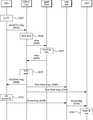
- FIG. 11illustrates a flow of processing legacy protocol messages in an SDN-based network to which the present invention is applied.
- FIG. 11illustrates an example of receiving a hello message of an Open Shortest Path First (OSPF) protocol from the first edge switch SW1.
- OSPFOpen Shortest Path First
- the first legacy router R1transmits a hello message Hello1 of the OSPF protocol to the first edge switch SW1. It may be (S410).
- the first edge switch SW1Since there is no flow entry for the received packet in the table 291 of the first edge switch SW1, the first edge switch SW1 sends a packet-in message to the controller 10 informing of an unknown packet. (S420).
- the packet-in messagepreferably includes a flow having a Hello1 packet and incoming port (port 11) information.
- the message management module 130 of the controller 10may determine whether to generate a processing rule for the flow (S430). See FIG. 10 for details of the determination method. In this example, since the OSPF protocol message is a packet that cannot be interpreted by the controller 10, the controller 10 may transfer the flow to the legacy routing agent 300 (S440).
- the SDN interface module 345 of the legacy routing agent 300may transmit the Hello1 packet received from the controller 10 and the virtual router 340 corresponding to the inlet port port 11 of the first edge switch SW1 provided in the flow. Can be sent to port 11v.
- the routing processor 330may generate legacy routing information of the Hello1 packet based on the routing table 335 (S450).
- the routing processing unit 330generates a Hello2 message corresponding to the Hello1 message, and designates a routing path for designating an output port as the 11v port so as to transmit the Hello2 packet to the first legacy router R1. Can be generated.
- the Hello2 messagehas a destination that is the first legacy router R1 and a predetermined virtual router identifier.
- the legacy routing informationmay include a Hello2 packet and an output port which is an eleventh port.
- the Hello1 packetis introduced into the virtual router 340, but the present invention is not limited thereto.
- the routing processor 330may generate legacy routing information using the information of the virtual router 340.
- the SDN interface module 345may transfer the generated legacy routing information to the legacy interface module 145 of the controller 10 (S460). Any one of the SDN interface module 345 and the legacy interface module 145 may convert the eleventh port port 11v, which is an output port, into an eleventh port 11 of the first edge switch SW1. Alternatively, port conversion may be omitted by making the names of the eleventh port and the eleventh port the same.
- the route calculation module 125 of the controller 10may output the Hello2 packet to the eleventh port port 11 of the first legacy router R1 using the legacy routing information received through the legacy interface module 145.
- the pathmay be set (S470).
- the message management module 130generates a packet-out message for outputting the Hello2 packet to port 11, which is an incoming port, by using the established route and legacy routing information, and transmits the packet-out message to the first legacy router R1. It may be (S480).
- the legacy routing agent 300may generate an OSPF hello message that is actively output to the edge port of the edge switch, and send it to the controller 10.
- the controller 10may transmit the hello packet to the openflow switch in a packet-out message.
- the present embodimentcan be implemented by setting the OpenFlow switch to follow the instruction of the packet-out message even for a packet-out message that does not correspond to the packet-in message.
- FIG. 12illustrates a case where a general legacy packet is transmitted from the first edge switch SW1 to the third edge switch SW3.
- the first edge switch SW1starts by receiving a legacy packet P1 whose destination IP address does not belong to the openflow switch group from the first legacy router R1 (S610).
- the first edge switch SW1may transmit the packet P1 to the controller 10 and inquire of a flow process (packet-in message) (S620).
- a flow processpacket-in message
- the message management module 130 of the controller 10may determine whether SDN control of the flow is possible (S630). In this example, the packet P1 is interpretable but directed towards the legacy network, so the controller 10 cannot create a path for the packet P1. Accordingly, the controller 10 may transmit the packet P1 and the eleventh port, which is an incoming port, to the legacy routing agent 300 through the legacy interface module 145 (S640).
- the routing processing unit 330 of the legacy routing agent 300generates the legacy routing information of the packet P1 with respect to the packet P1 received from the controller 10 based on the information of the virtual router 340 and the routing table 335. Can be (S650). In this example, it is assumed that packet P1 should be output to port 32v of the virtual router.
- the legacy routing informationincludes an output port that is a 32v port (port 32v) for the packet P1, a destination MAC address that is a MAC address of the second legacy router R2, and a source MAC that is a MAC address of the 32v port. May contain an address. This information is header information of the packet output from the legacy router.
- the header information of the packet P1is as follows. Since the source and destination IP addresses are the same as the header information when the packet P1 is generated, they will be omitted in this description.
- the source MAC address of the packet P1is the MAC address of the output port of the router R1.
- the destination MAC address of the packet P1is the MAC address of the eleventh port port 11v of the virtual legacy router v-R0. If the existing router, the packet P1 'output to the 32v port (port 32v) of the virtual legacy router (v-R0) may have the following header information.
- the source MAC address of the packet P1 'is the MAC address of the 32v port (port 32v) of the virtual legacy router (v-R0), and the destination MAC address is the MAC address of the inlet port of the second legacy router. That is, part of the header information of the packet P1 is changed during legacy routing.
- the routing processor 330may generate the packet P1 ′ in which the header information of the packet P1 is adjusted and include it in the legacy routing information.
- the routing processing unit 330does not generate the packet P1 'which changes the header information of the packet P1.
- the controller 10 or the legacy routing agent 300must process the incoming packet for the same packet or a similar packet having the same destination address range each time. Therefore, the step of transforming the packet into the format after the existing routing is performed by the packet switch at the edge switch (in this example, the third edge switch SW3) which outputs the packet to the external legacy network rather than the legacy routing agent 300. It is preferable.
- the legacy routing information described abovemay include a source and a destination MAC address.
- the controller 10may use the routing information to transmit a flow-mod message to change the header information of the packet P1 to the third edge switch.
- the SDN interface module 345may transfer the generated legacy routing information to the legacy interface module 145 of the controller 10 (S660). In this step, the output port can be converted to an edge port to be mapped.
- the controller 10may generate a flow processing rule inside the openflow switch group by using the legacy routing information received through the legacy interface module 145, in particular, the legacy path of the legacy routing information.
- the path calculation module 125 of the controller 10may calculate a path to be output from the first edge switch SW1 to the 32nd port of the third edge switch SW3 by using the legacy path (S670).
- the message management module 130transmits a packet-out message specifying an output port for the packet P1 to the first edge switch SW1 based on the calculated path (S680) and flows to the openflow switch of the corresponding path.
- a change (flow-Mod) change messagemay be transmitted (S690 and S700).
- the message management module 130may also transmit a flow-mod message to define the processing for the same flow to the first edge switch SW1.
- the flow entry according to the flow processing ruleis preferably based on an identifier identifying that it is a data-packet corresponding to the flow managing the path of the packet P1. That is, the flow processing for the packet P1 is preferably performed based on the identifier for identifying the legacy flow.
- the packet-out message transmitted to the first edge switch SW1includes a packet P1 to which a legacy ID is added, and the flow change message includes a flow entry for adding a legacy ID to the packet-out message. It can be included. See FIG. 13 for an example of a flow table of each switch.
- FIG. 13Ais a flow table of the first edge switch SW1. For example, Table 0 of FIG.
- 13 (a)adds tunnel2 to the flow with a legacy identifier to the flow destined for the second legacy router R2 and moves the flow to Table 1.
- Legacy identifiersmay be written in metafields or other fields.
- Table 1has a flow entry for outputting the flow having tunnel2 to the 14th port (port information of the first switch SW1 connected to the fourth switch SW4).
- 13Bis an example of a flow table of the fourth switch SW4.
- the table of FIG. 13 (b)allows the flow having the legacy identifier of tunnel2 to be output to port 43 connected to the third switch SW3.
- 13Cis an example of a flow table of the third switch SW3.
- Table 0 of FIG. 13Cremoves the legacy identifier of the flow whose legacy identifier is tunnel2 and moves the flow to Table 1.
- FIG. Table 1outputs the flow to the 32nd port. Using multiple tables in this way can reduce the number of cases. This enables quick searching and can reduce resource consumption such as memory.
- the first edge switch SW1may add a legacy ID (tunnel ID) to the packet P1 (S710) or transmit a packet to which the legacy ID (tunnel ID) is added to the core network (S720).
- the core networkrefers to a network composed of open flow switches SW2, SW4, and SW5, not edge switches SW1 and SW3.
- the core networkmay transmit the flow to the third edge switch SW3 (S730).
- the third edge switch SW3may remove the legacy identifier and output the packet P1 to the designated port (S740).
- the flow table of the third switch SW3preferably includes a flow entry for changing the destination and source MAC addresses of the packet P1.
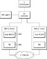
- FIG. 14is a structural diagram showing a container network management system according to an embodiment of the present invention
- FIG. 15is a block diagram of a host mainly showing the internal structure of the host of FIG. 14, and
- FIG. 16is an embodiment of the present invention.
- 17is a structural diagram illustrating another host internal structure of FIG. 14,
- FIG. 18is a schematic diagram of FIG. 14, and
- FIG. 19is a network structural diagram of FIG. 18 converted to a legacy virtual router. to be. See FIGS. 1 to 13.
- the container network management systemincludes an orchestrator 1, a controller 10, a legacy routing agent 300, and a plurality of hosts 800-1 and 800-2; Or to specify all).
- the orchestrator 1allows container creation / deletion to each host 800-1 and 800-2 according to a user request or policy, controls the internal network environment, and controls each host 800-1 and 800-2. Manage networks between containers.
- the orchestrator 1may control each host 800-1 and 800-2 through the controller 10.
- the legacy routing agent 300may generate legacy routing information of the corresponding packet and transmit the packet to the controller 10. If necessary, the legacy routing agent 300 may generate legacy protocol conversion information for the packet to conform to the legacy protocol or convert the packet to conform to the legacy protocol.
- Legacy protocolsinclude legacy routing protocols.
- the generated routing information or protocol conversion informationmay be stored as a table in the controller 10 or each host 800-1 and 800-2, in which case the controller 10 processes the packet to the legacy routing agent 300. There is no need to contact.
- the host 800may provide an SDN-based virtual switch and container.
- the host 800may be a server having a physically based computing function, but is not limited thereto.
- the host 800includes a host controller 810, an SDN-based virtual switch 820 (vSW), a container bridge 830, a container 840, a host storage unit 860 (DB), And real network interfaces 850 and 852.
- the host storage unit 860may store a program for processing and controlling the host controller 810.
- the host storage unit 860may store bridge net information and container net information, which will be described later, in a DB format list.
- the host storage unit 860may store data necessary for the virtual switch 820 or store various identifiers.
- the host controller 810may control the operation of each element of the host 800 to control the overall operation of the host 800.
- the host controller 810may generate a virtual switch 820, a container bridge 830, and a container 840.
- the host controller 810may network couple the virtual switch 820, the container bridge 830, the container 840, and the like so that the network can be networked with each other.
- the host controller 810may exchange data with the controller 10 and / or the external public network 5 (eg, the 'Internet') through the first and second physical network interfaces 850 and 852. .
- the first and second real network interfaces 850 and 852may be implemented as one network interface.
- the virtual switch 820may correspond to the switch 20 of FIG. 1.
- the virtual switch 820may correspond to an edge switch in particular of the switch group of FIG. 6.
- the virtual switch 820may be virtually generated by the host controller 810.
- the virtual switch 820may exchange a message with the controller 10 through the first physical network interface 850.
- the virtual switch 820may exchange packets with the external network 5 through the second physical network interface 852.
- the second physical network interface 852can operate like the network interface of the virtual switch 820.
- the virtual switch 820may perform an L2 / L3 network between containers within the same host and / or between each container of another host.
- the container bridge 830is generated by the host controller 810 and may serve as a bridge between containers in the same server (host).
- the container bridge 830may serve as a hub, a bridge, and / or a switch among existing network equipment.
- the container bridge 830may perform an L2 network function between containers.
- Container bridge 830may include routing between containers belonging to different domains (networks), networks with containers belonging to different hosts, when the destination of packets is associated with virtual switch 820, and / or incoming packets from containers. If there is no processing information, the incoming packet from the container may be transmitted to the virtual switch 820.
- the container bridge 830may be virtually network coupled with the virtual NI 821 of the virtual switch 820 via a bridge-switch NI (Network Interface) 832.
- the container bridge 830may be network coupled with the virtual NI 841 of the container 840 via the bridge-container 831.
- Container bridge 830may have a bridge identifier that identifies itself.
- the bridge identifiermay distinguish the sub network environment established by the container bridge 830 from other network environments.
- the bridge identifiermay be connected with network subnet information and gateway information.
- Network subnet informationis needed for the IP address to be assigned to the container 840, and gateway information is needed for routing.
- the gateway informationmay initially have information (IP address, Mac address, etc.) for the second real network interface 852 connected with the external network 5 by default.
- Network subnet information and gateway information connected based on the bridge identifiermay be DBized as bridge net information.
- the network subnet informationmay be provided with a plurality of pieces of information such that two or more sub networks are established.
- the plurality of network subnet informationmay be divided into domain tags to be described later.
- the container 840is a kind of virtual machine in which applications operate independently, but unlike the existing virtual machine, the container 840 is a kind of lightweight virtual machine that can operate lighter than the virtual machine by sharing an OS.
- the container 840may provide one or more services.
- the container 840may establish an independent network environment on the OS, and configure a network topology through a virtual interface in the network environment. If the OS is Linux, an independent network environment can be implemented with namespace technology.
- the inventionrelates in particular to a method of networking between containers 840.
- Container 840has a container identifier.
- the container 840may inherit the bridge identifier of the upper container bridge 830.
- the container 840may have the same domain identifier indicating the same domain.
- the container 840has an IP address, and the IP address may be generated based on the bridge net information by a DHCP server (not shown).
- the DHCP serveris preferably located outside the host 800. This is because you need to generate an IP address for other hosts.
- the DHCP servermay be implemented virtually, in which case the DHCP server may be created inside the controller 10 and / or the legacy routing agent 300. Using the container identifier as a key, the IP address and the same domain identifier may be stored as a container net information list.
- the container bridge 830may designate the domain tag corresponding to the same domain identifier to the bridge-container NI 831 based on the same domain identifier of the container 840.
- the same domain identifier and the domain tagmay be the same.
- the container bridge 830may tag a tag designated to the bridge-container NI 831 to which the packet flows in a packet flowing from the container 840.
- the domain tagmay use packet fields such as vLAN, vxLAN, or metadata.
- Container bridge 830may leak the packet to a domain-tagged bridge-container NI 831 tagged with the packet. As a result, the container bridge 830 may provide container communication in the same host and the same network. As a result, unnecessary broadcast or multicast traffic can be reduced. Outgoing and / or outgoing packets at the bridge-switch NI 832 of the container bridge 830 may go in and out regardless of the domain tag of the outgoing packet.
- Bridge-container NI 831 and bridge-switch NI 832may each have an associated MAC address.
- the bridge-container NI 831may use the ARP protocol or know the MAC address of each container from the information received from the controller 10.
- the MAC information received from the controller 10may be obtained from container net information previously stored as a member of the list.
- the bridge-switch NI 832may have the MAC address of the gateway (the second physical network interface 852 or the virtual Mac address, described below), and the MAC address of a container belonging to the same domain of another host.
- the container bridge 830may exit the incoming packet to the appropriate NI of the bridge-container NI 831 and the bridge-switch NI 832 through the destination MAC address of the incoming packet. If none of the bridge-container NI 831 and bridge-switch NI 832 is associated with the MAC address of the incoming packet, then the container bridge 830 may exit the incoming packet to the bridge-switch NI 832.
- the host controller 810may generate a virtual switch 820 (S900).
- the virtual switch 820may be generated when the host 800 is booted, or may be generated when the container creation message or the container bridge creation message is received from the orchestrator 1 or the controller 10.
- the host controller 810may include the virtual switch 820 and the second physical network interface 852 so that the virtual switch 820 may exchange packets with the external network 5 through the second physical network interface 852. Can be connected (S905).
- the host controller 810may generate the container bridge 830 (S910).
- the container bridge creation messagemay include a bridge identifier, gateway information, and network subnet information. If there is an identical bridge identifier, the host controller 810 may transmit a failure message to the controller 10.
- the network subnet informationmay establish sub-networks equal to or greater than the number of domain tags.
- the plurality of subnet information for constructing two or more sub-networksmay be associated with a domain tag or the same domain identifier.
- the container bridge generation messagemay further include the same domain identifier (or domain tag) list. Elements of the domain tag list and each of the plurality of subnet information of the network subnet information are associated with each other.
- the host controller 810may network couple the virtual NI of each of the virtual switch 820 and the container bridge 830 (S915).
- the packetmay be forwarded from the container bridge 830 to the virtual switch 820 regardless of its domain tag.
- the host controller 810may generate a container 840 (S930).
- the container creation messagemay include a bridge identifier, a container identifier, and the same domain identifier.
- the host controller 810may process an error when the same container identifier exists or the bridge identifier does not exist.
- the host controller 810may allocate a unique IP address to the container 840 using the DHCP function (S935).
- the host controller 810may network couple the container bridge 830 and the container 840 (S840).
- the host controller 810may designate a domain tag associated with the same domain identifier of the container 840 to the bridge-container NI 831 (S845).
- the host 800may be implemented in an embodiment having various virtual switches and container bridges. Referring to FIG. 17, two container bridges may be provided in one virtual switch like the first host 800-3 or two virtual switches may be provided like the third host 800-5. The first and third hosts 800-3 and 800-5 may be treated like the second host 800-4. This may be implemented by configuring a connection structure between the bridge-switch NI 832 and the virtual NI 821 of the virtual switch 820 as a trunk structure or a plurality of subchannels. You can also control two or more hosts as if they were one host.
- Two or more hostsare connected to other external switches, such as the first host (800-3) and the second host (800-4), or the second host (800-4) and the third host (800-5) It can be connected through tunneling across other networks, such as:
- the other networkmay be the same as the external network 5 connected to the second host 800-4.
- the virtual switch vSW not directly connected to the external network 5 of FIG. 17may correspond to a switch constituting the core network of FIG. 6.
- the first and second hosts h1 and h2are connected through one legacy router R0, and the first host h1 is connected to the first virtual switch vSW1 and the first container bridge CT.Br.1. ), And first to third containers ct1, ct2, and ct3, and the second host h2 includes a second virtual switch vSW2, a second container bridge CT.Br.2, and a fourth To fifth containers ct4 and ct5.
- the domain tagwill use vLAN, and the first, second, and fourth containers (ct 1, 2, 4) are connected to the bridge-container NI with vLAN 100, respectively, and the third and fifth containers (ct3). ct5) are each connected to a bridge-container NI with vLAN 200.
- the first and second hosts h1 and h2 of FIG. 17may be interpreted by the legacy routing agent 300 as a topology structure as shown in FIG. 19 in the legacy router R0.
- the first and second hosts h1 and h2are virtual ports 1-0 and 2-0 virtual routers (vR.), Each of which has a physical network interface connected to the legacy router R0 as a virtual port, as shown in FIG. I.0, vR.II.0) or first-first, first-second, second-first, and second-second virtual routers generated by domain tags as shown in FIG. 19 (b).
- the first to fifth containers ct1 to ct5may correspond to the external network vN of FIG. 7.
- Virtual port information(P.vR.I.0, P.vR.) connected to the legacy router (R0) of the 1-0 and 2-0 virtual routers (vR.I.0, vR.II.0). II.0) preferably comprises the actual network interfaces (IP address and MAC address) of the first and second hosts h1 and h2, respectively.
- the virtual port information (P.vR.I.1, P.vR.I.2, P.vR.II.1, P.vR.II.2) connected to the router R0has a virtual MAC address. It is preferable to have an IP address having the same network as the legacy router R0.
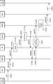
- FIGS. 20 through 23are signal flow diagrams for packet flows from one container to another. Reference is made to FIGS. 1 to 19, in particular FIGS. 14 to 19.
- FIGS. 1 to 19the network topology structure of FIG. 18 is assumed and described with reference to FIG. 19A.
- each container, container bridge, and / or virtual switchknows the MAC address of an ARP message or controller 10 (ctr) from another container belonging to the same domain, and assumes that the container has only one virtual port. do.
- FIG. 20illustrates a packet flow from a first container ct1 belonging to the same host and the same domain to a second container ct2. Since the first and second containers ct1 and ct2 belong to the same domain, the first packet pk1 generated by the first container ct1 is the IP of the second container ct2 and the aerosols a2 and m2. Has the destination IP and MAC address.
- the first container ct1may transfer the first packet pk1 to the first container bridge CT.Br. 1 (S1010). Since the first container bridge CT.Br. 1 knows the bridge-container NI associated with the beer yard m2, the first container bridge CT.Br.1 may directly transfer the first packet pk1 to the second container ct2 (S1020).
- FIG. 21illustrates packet flow from a first container ct1 belonging to the same host and a heterogeneous domain to a third container ct3. Since the first and third containers ct1 and ct3 belong to different domains, the first container ct1 converts the MAC address of the destination into a gateway address, that is, the MAC address of the actual network interface of the first host h1 (m. A second packet pk2 of h1) can be generated. The first container ct1 may transfer the generated second packet pk2 to the first container bridge CT.Br. 1 (S1110).
- the first container bridge CT.Br.1may tag the domain tag 100 associated with the first container ct1 to the vLAN field (S1115).
- the first container bridge CT.Br.1is a second packet (pk2 [100]) having a vLAN of 100 to the first virtual switch vSW1 through the bridge-switch NI associated with the gateway, ie, m.h1. It may be delivered (S1120).
- the first virtual switch vSW1may determine whether there is a flow entry of the destination IP address of the second packet pk2 [100]. If there is no flow entry, the first virtual switch vSW1 may transmit a second packet pk2 [100] to the controller 10 to request flow processing information (S1130).
- Step S1135may be performed at the first virtual switch vSW1.
- the first container bridge CT.Br.1may remove the vLAN information of the second packet pk2 and then transfer it to the second container ct2.
- FIG. 22illustrates a packet flow from a heterogeneous host and a first container ct1 belonging to the same domain to a fourth container ct4. Since the first and fourth containers ct1 and ct4 belong to the same domain, the first container ct1 receives the third packet pk3 whose MAC address of the destination is the MAC address m4 of the fourth container ct4. Can be generated. The first container ct1 may transfer the generated third packet pk3 to the first container bridge CT.Br. 1 (S1210).
- the first container bridge CT.Br.1may tag the domain tag 100 associated with the first container ct1 in the vLAN field.
- the MAC address learning of the fourth container ct4is not performed in the first container bridge CT.Br.1 or the MAC address m4 is bridged through the MAC address learning or information received from the controller 10.
- the switch NIis specified, the outgoing port of the packet becomes the bridge-switch NI. Accordingly, the first container bridge CT.Br.1 transmits the third packet pk3 through the bridge-switch NI to the first virtual switch vSW1 with the third packet pk3 [100]. Can be delivered (S1215).
- the first virtual switch vSW1may determine whether there is a flow entry of the destination IP address of the third packet pk3 [100]. If there is no flow entry, the first virtual switch vSW1 may transmit a third packet pk3 [100] to the controller 10 to request flow processing information (S1220).
- the controller 10knows the network information of the second container ct2. Accordingly, the controller 10 may convert the third packet pk3 into a domain tag associated with the domain identifier to which the second container belongs (S1225). Since the third packet pk3 will be delivered to the external network 5, it is preferable to designate another vLAN even in the same domain. However, the third packet pk3 may maintain the original vLAN.
- the controller 10determines whether there is legacy protocol conversion information of the third packet pk3, and if not, the controller 10 transmits the legacy packet to the legacy routing agent 300. 3 packets (pk3 [10]) can be delivered (S1230).
- the legacy routing agent 300converts the destination MAC address of the third packet pk3 [10] into the MAC address (m.R1) of the network interface of the legacy router R9 connected with the first host h1, and the source The MAC address may be converted into a MAC address (m.h1) of the actual network interface of the first host (S1235). This step may be performed in the controller 10 or the first virtual switch vSW1.
- the converted third packet pk3 [10]may be delivered to the controller 10 and the first virtual switch vSW1 (S1240 and S1245), and may be delivered from the first virtual switch vSW1 to the legacy router R0. There is (S1250).
- the legacy router R0connects the destination and source MAC address of the third packet pk3 with the MAC address m.h2 of the actual network interface of the second host h2 and the second host of the legacy router R0. Can be converted into the MAC address (m.R2) of the interface (S1255).
- the legacy router R0may transmit the third packet pk3 [10] to the second virtual switch vSW2 (S1260).
- the second virtual switch vSW2converts the domain tag (vLAN is 100) associated with vLAN 10, which is the domain tag of the third packet pk3, and converts the destination / source MAC address from (m.h2 / m.R2) to ( m2 / m1) (S1265).
- the converted third packet pk3 [100]may be transmitted from the second virtual switch vSW2 to the fourth container ct4 through the second container bridge CT.Br.2 (S1270). S1275).
- FIG. 23illustrates a packet flow from a first container ct1 belonging to a heterogeneous host and a heterogeneous domain to a fifth container ct5. Since the first and fifth containers ct1 and ct5 belong to different domains, the first container ct1 converts the MAC address of the destination into a gateway address, that is, the MAC address of the actual network interface of the first host h1 (m. A fourth packet pk4 referred to as h1) can be generated. The first container ct1 may transfer the generated fourth packet pk4 to the first container bridge CT.Br. 1 (S1310).
- the first container bridge CT.Br.1may tag the domain tag 100 associated with the first container ct1 in the vLAN field.
- the first container bridge CT.Br.1is a fourth packet (pk4 [100]) having a vLAN of 100 to the first virtual switch vSW1 through the bridge-switch NI associated with the gateway, ie, m.h1. Can be delivered (S1315).
- the first virtual switch vSW1may determine whether there is a flow entry of the destination IP address of the fourth packet pk4 [100]. If there is no flow entry, the first virtual switch vSW1 may transmit a fourth packet pk4 [100] to the controller 10 in order to request flow processing information (S1320).
- the controller 10knows the network information of the fifth container ct5. Accordingly, the controller 10 may convert the domain tag of the fourth packet pk4 into a domain tag associated with the domain identifier to which the fifth container ct5 belongs (S1325). Since the fourth packet pk4 will be delivered to the external network 5, it is preferable to designate another vLAN even in the same domain. It is also desirable to use domain tags to distinguish them from packets that are homogeneous hosts and homogeneous domains. For example, if the source container of the packet to the fifth container ct5 is in the same domain as the fifth container ct5, the vLAN value of the fourth packet pk4 is set to 20, and in the heterogeneous domain, the fourth packet pk4 is used. ) Can be set to 21. Since the first and fifth containers ct1 and ct5 are heterogeneous domains, the controller 10 may convert the domain tag of the fourth packet pk4 to 21.
- the controller 10determines whether there is legacy protocol conversion information of the third packet pk3, and if not, the third packet pk3 is transmitted to the legacy routing agent 300. pk3 [10]) (S1330).
- the legacy routing agent 300converts the destination MAC address of the third packet pk3 [10] into the MAC address (m.R1) of the network interface of the legacy router R9 connected with the first host h1, and the source The MAC address may be converted into a MAC address (m.h1) of the actual network interface of the first host (S1335). This step may be performed in the controller 10 or the first virtual switch vSW1.
- the converted fourth packet pk4 [21]may be delivered to the controller 10 and the first virtual switch vSW1 (S1340 and S1345), and may be delivered from the first virtual switch vSW1 to the legacy router R0. There is (S1350).
- the legacy router R0may connect the destination and source MAC addresses of the fourth packet pk4 with the MAC address m.h2 of the actual network interface of the second host h2 and the second host of the legacy router R0.
- the MAC address of the interface (m.R2)can be converted (S1355).
- the legacy router R0may transmit the fourth packet pk4 [21] to the second virtual switch vSW2 (S1360).
- the second virtual switch vSW2converts the domain tag (vLAN is 200) associated with vLAN 21, which is the domain tag of the fourth packet pk4, and converts the destination / source MAC address from (m.h2 / m.R2) to ( m2 / m.h1) (S1365).
- the converted fourth packet pk4 [200]may be transmitted from the second virtual switch vSW2 to the fifth container ct5 through the second container bridge CT.Br.2 (S1370). S135).
- the present inventionmay be implemented in hardware or software.
- the inventionmay also be embodied as computer readable code on a computer readable recording medium.
- the computer-readable recording mediumincludes all kinds of recording devices in which data that can be read by a computer system is stored. Examples of computer-readable recording media include ROM, RAM, CD-ROM, magnetic tape, floppy disks, optical data storage devices, and the like, which are also implemented in the form of carrier waves (for example, transmission over the Internet). Include.
- the computer readable recording mediumcan also be distributed over network coupled computer systems so that the computer readable code is stored and executed in a distributed fashion. And functional programs, codes and code segments for implementing the present invention can be easily inferred by programmers in the art to which the present invention belongs.
- Embodiments of the present inventionmay include a carrier wave having electronically readable control signals that may be operated with a programmable computer system on which one of the methods described herein is executed.
- Embodiments of the present inventionmay be implemented as a computer program product having a program code, the program code being operated to execute one of the methods when the computer program is run on a computer.
- the program codemay for example be stored on a machine readable carrier.
- One embodiment of the inventionmay be a computer program having program code for executing one of the methods described herein when the computer program is run on a computer.
- the inventionmay include a computer, or a programmable logic device, for performing one of the methods described above. Programmable logic devices (eg, field programmable gate arrays, complementary metal oxide semiconductor based logic circuits) may be used to perform some or all of the functions described above.
- controller 20SDN switch
- topology management module 125path calculation module
Landscapes
- Engineering & Computer Science (AREA)
- Computer Networks & Wireless Communication (AREA)
- Signal Processing (AREA)
- Data Exchanges In Wide-Area Networks (AREA)
Abstract
Description
Translated fromKorean본 발명은 SDN(Software Defined Network) 기반의 컨테이너 네트워크 관리 시스템 및 컨테이너 네트워크의 컨테이너 네트워킹 방법에 관한 것으로, 컨테이너 사이의 L2/L3 네트워크가 가능하도록 하며, 불필요한 멀티캐스트 및 브로드캐스트 트래픽을 줄일 수 있고, 탄력적인 네트워크 운용이 가능하도록 하며, 레거시 네트워크와 SDN 네트워크 사이의 패킷 흐름을 가능하도록 하는 관리 시스템 및 네트워킹 방법에 관한 것이다.The present invention relates to a software defined network (SDN) -based container network management system and a container networking method of a container network, to enable L2 / L3 networks between containers, to reduce unnecessary multicast and broadcast traffic, The present invention relates to a management system and a networking method for enabling flexible network operation and enabling packet flow between a legacy network and an SDN network.
휴대 장치 및 서버 가상화의 폭발적인 증가와 클라우드 서비스의 출현으로, 네트워크 수요가 늘어났다. SDN은 어플리케이션에서 추상화된 기본적인 네트워크 인프라 구조이며, 논리적으로 중앙 집중적인 네트워크 인텔리전스(network intelligence)이며, 제어 플레인과 데이터 플레인이 분리되어 있는 것을 특징으로 한다.With the explosion of mobile device and server virtualization and the advent of cloud services, network demand has increased. SDN is a basic network infrastructure abstracted from the application, logically centralized network intelligence, and separated from the control plane and data plane.
오픈 플로우는 고속 패킷 전달과 높은 레벨의 라우팅 결정 기능들을 분리한다. 패킷 포워딩 플레인은 여전히 스위치 단에 관여되며, 반면 고수준 라우팅 결정은 분리된 컨트롤러에서 관여되며, 이들은 오픈 플로우 프로토콜을 통해 통신한다.Open flow separates high speed packet delivery and high level routing decision functions. The packet forwarding plane is still involved in the switch stage, while high-level routing decisions are involved in separate controllers, which communicate through open flow protocols.
그러나 기존 네트워크에서 SDN으로의 전환 과도기로서, 기존 프로토콜과 장치와 상호 작용하는 소프트웨어 정의 네트워크의 필요성이 있다. 이러한 하이브리드 SDN 네트워크를 구성하는 장비는 컴퓨팅 자원이나 네트워킹 자원 소모가 적으며, 단순한 구조를 가질 필요가 있다.However, as a transitional transition from existing networks to SDN, there is a need for software defined networks that interact with existing protocols and devices. The equipment constituting the hybrid SDN network consumes less computing resources or networking resources and needs to have a simple structure.
기존의 가상 머신과는 상이한 경량화된 컨테이너가 가상 머신 대신 사용되고 있다. 컨테이너는 네트워크 관리가 존재하지 않으며, 모든 컨테이너들이 동일 L2 도메인에 존재하도록 되어 있었다. 이는 네트워크의 정책 관리가 어렵게 하며, 서비스별 네트워크 기능을 관리하기 힘들게 하는 요소가 되었다. 또한 컨테이너와 외부 네트워크 간의 연동을 제공하는 서비스가 존재하지 않았다. 기존 클라우드 기반의 서빗의 경우, 각 서비스별 프론트엔드/백엔드(FrontEnd/BackEnd) 네트워크의 관리가 요구된다. 프론트엔드만 공개(public)된 네트워크에서의 접근이 가능하도록 하고, 나머지 컴퓨팅 작업은 사설(privatge) 영역인 백엔드 네트워크에서만 동작되도록 하기 위해서이다. 컨테이너는 이러한 네트워크 관리 메커니즘이 존재하지 않아, 실제적인 서비스를 하기에 네트워크 관리 측면에 어려움이 있다.Lightweight containers, which are different from existing virtual machines, are used instead of virtual machines. Containers do not have network management, and all containers are in the same L2 domain. This makes it difficult to manage the policy of the network and makes it difficult to manage network functions by services. In addition, there was no service providing interworking between containers and external networks. In the case of the existing cloud-based service, management of frontend / backend networks for each service is required. Only the front end is accessible from the public network, and the rest of the computing work is done only on the back end network, which is private. Containers do not have such a network management mechanism, which makes it difficult to manage the network.
<선행기술문헌><Preceding technical literature>
비특허문헌 1. OpenFlow Switch Specification version 1.4.0(Wire Protocol 0x05), October 14, 2013 [https://www.opennetworking.org/images/stories/downloads/sdn-resources/onf-specifications/openflow/openflow-spec-v1.4.0.pdf]Non-Patent
비특허문헌 2. Software-Defined Networking: The New Norm for Netwrks, ONF White Paper, April 13, 2012 [https://www.opennetworking.org/images/stories/downloads/sdn-resources/white-papers/wp-sdn-newnorm.pdf]Non-Patent Document 2: Software-Defined Networking: The New Norm for Netwrks, ONF White Paper, April 13, 2012 [https://www.opennetworking.org/images/stories/downloads/sdn-resources/white-papers/wp -sdn-newnorm.pdf]
비특허문헌 3. ETSI GS NFV 002 v1.1.1 (2013-10)Non-Patent Document 3: ETSI GS NFV 002 v1.1.1 (2013-10)
[http://www.etsi.org/deliver/etsi_gs/NFV/001_099/002/01.01.01_60/gs_NFV002v010101p.pdf][http://www.etsi.org/deliver/etsi_gs/NFV/001_099/002/01.01.01_60/gs_NFV002v010101p.pdf]
본 발명의 목적은 컨테이너의 네트워크 관리가 가능하도록 하며, L2/L3 네트워크가 가능하도록 하는 네트워크 환경을 제공하고, 컨테이너 운용 아래에서 외부 네트워크와 분리된 사설 네트워크가 가능하도록 하는 네트워크 관리 시스템 및 그 방법을 제공하는 데 있다.SUMMARY OF THE INVENTION An object of the present invention is to provide a network environment for enabling container management of a container, to provide a network environment for enabling L2 / L3 networks, and to enable a private network separate from an external network under container operation. To provide.
또한, SDN 기반의 컨테이너 네트워크에서 레거시 네트워크를 지원할 수 있도록 하는 시스템 및 그 방법을 제공하는 데 또 다른 목적이 있다.In addition, another object of the present invention is to provide a system and method for supporting a legacy network in an SDN-based container network.
본 발명에 따른 컨테이너 네트워크 관리 시스템은, 레거시 네트워크에 연결되는 실제 네트워크 인터페이스; 상기 실제 네트워크 인터페이스를 통해 레거시 네트워크와 패킷을 주고 받는, SDN(Software Defined Network) 기반의 가상 스위치; 상기 가상 스위치를 생성하는 호스트 제어부; 상기 호스트 제어부에 의해 생성되며, 브리지-스위치 NI(Network Interface)를 통해 상기 가상 스위치와 가상으로 네트워크 커플링되며, 자신을 식별하는 브리지 식별자를 구비하는 컨테이너 브리지; 상기 브리지 식별자를 기초로 네트워크 서브넷 정보 및 상기 실제 네트워크 인터페이스를 게이트웨이로 하는 게이트웨이 정보를 브리지 넷 정보로 저장하는 데이터베이스; 및 상기 호스트 제어부에 의해 생성되고, 상기 브리지 넷 정보를 기초로 고유 IP 주소를 할당받으며, 상기 컨테이너 브리지에 가상으로 네트워크 커플링되는 복수의 컨테이너를 구비하는 제1 호스트를 포함할 수 있다.The container network management system according to the present invention includes a real network interface connected to a legacy network; A software defined network (SDN) -based virtual switch that exchanges packets with a legacy network through the real network interface; A host controller generating the virtual switch; A container bridge generated by the host controller and virtually network coupled with the virtual switch through a bridge-switch network interface (NI), the container bridge having a bridge identifier identifying itself; A database for storing network subnet information and gateway information using the actual network interface as a gateway based on the bridge identifier as bridge net information; And a first host generated by the host controller, assigned with a unique IP address based on the bridge net information, and having a plurality of containers virtually network coupled to the container bridge.
본 발명에 따른 호스트는, 레거시 네트워크에 연결되는 실제 네트워크 인터페이스; 상기 실제 네트워크 인터페이스를 통해 레거시 네트워크와 패킷을 주고 받고, 외부의 제어기에 의해 제어되는 SDN(Software Defined Network) 기반의 가상 스위치; 상기 가상 스위치를 생성하는 호스트 제어부; 상기 호스트 제어부에 의해 생성되며, 브리지-스위치 NI(Network Interface)를 통해 상기 가상 스위치와 가상으로 네트워크 커플링되며, 자신을 식별하는 브리지 식별자를 구비하는 컨테이너 브리지; 상기 브리지 식별자를 기초로 네트워크 서브넷 정보 및 상기 실제 네트워크 인터페이스를 게이트웨이로 하는 게이트웨이 정보를 브리지 넷 정보로 저장하는 데이터베이스; 및 상기 호스트 제어부에 의해 생성되고, 상기 브리지 넷 정보를 기초로 고유 IP 주소를 할당받으며, 상기 컨테이너 브리지에 가상으로 네트워크 커플링되는 복수의 컨테이너를 구비할 수 있다.The host according to the present invention comprises a real network interface connected to a legacy network; A software defined network (SDN) based virtual switch controlled by an external controller to exchange packets with a legacy network through the actual network interface; A host controller generating the virtual switch; A container bridge generated by the host controller and virtually network coupled with the virtual switch through a bridge-switch network interface (NI), the container bridge having a bridge identifier identifying itself; A database for storing network subnet information and gateway information using the actual network interface as a gateway based on the bridge identifier as bridge net information; And a plurality of containers generated by the host controller, assigned a unique IP address based on the bridge net information, and virtually network-coupled to the container bridge.
본 발명에 따른 컨테이너 네트워크의 컨테이너 네트워킹 방법은, 컨테이너를 생성하며 실제 네트워크 인터페이스를 통해 레거시 네트워크와 연결되는 호스트에서, SDN(Software Defined Network) 기반의 가상 스위치를 생성하는 단계; 상기 가상 스위치를 상기 실제 네트워크 인터페이스와 네트워크 연결하는 단계; 상기 호스트에서, 네트워크 환경을 구별하는 브리지 식별자, 상기 가상 스위치를 게이트웨이로 하는 게이트웨이 정보, 및 네트워크 서브넷 정보를 구비하는 컨테이너 컨테이너 브리지 생성 요청을 받으면, 컨테이너 브리지를 생성하는 단계; 상기 컨테이너 브리지와 상기 가상 스위치 사이에 모든 동일 도메인 식별자를 가지는 패킷이 통과할 수 있도록 상기 컨테이너 브리지와 상기 가상 스위치를 네트워크 커플링하는 단계; 상기 호스트에서, 상기 브리지 식별자를 키로 하는 제1 컨테이너 식별자 및 제1 동일 도메인 식별자를 구비하는 컨테이너 생성 요청을 받으면, 상기 제1 컨테이너 식별자를 구비하는 제1 컨테이너를 생성하는 단계; 상기 브리지 식별자에 연관된 네트워크 서브넷 정보를 기초로 상기 제1 컨테이너에 IP 주소를 할당하는 단계; 및 상기 컨테이너 브리지와 상기 제1 컨테이너를 네트워크 커플링하고, 상기 제1 동일 도메인 식별자에 연관된 제1 도메인 태그를 가진 패킷만 상기 제1 컨테이너로 전달되도록 상기 컨테이너와 커플링되는 상기 컨테이너 브리지의 브리지-컨테이너 NI(Network Interface)에 상기 제1 도메인 태그를 지정하는 단계를 포함할 수 있다.A container networking method of a container network according to the present invention includes: creating a container and creating a virtual switch based on a software defined network (SDN) in a host connected to a legacy network through an actual network interface; Networking the virtual switch with the real network interface; When the host receives a container container bridge creation request including a bridge identifier for distinguishing a network environment, gateway information using the virtual switch as a gateway, and network subnet information, generating a container bridge; Network coupling the container bridge and the virtual switch such that packets having all the same domain identifiers pass between the container bridge and the virtual switch; When the host receives a container creation request including a first container identifier having a bridge identifier as a key and a first same domain identifier, generating a first container having the first container identifier; Assigning an IP address to the first container based on network subnet information associated with the bridge identifier; And a bridge of the container bridge coupled to the container such that the container bridge and the first container are network coupled and only packets with a first domain tag associated with the first same domain identifier are delivered to the first container. And assigning the first domain tag to a container network interface (NI).
본 발명에 따르면, SDN 기반의 컨테이너 네트워크에서 컨테이너의 네트워크 관리가 가능하며, 컨테이너 간의 L2/L3 네트워킹을 제공하며, 공용 외부 네트워크와 서비스가 운용되는 사설 네트워크로 분리할 수 있으며, 레거시 네트워크와 통신이 가능하여 기존의 레거시 네트워크 장비를 그대로 이용할 수 있다.According to the present invention, it is possible to manage a network of containers in an SDN-based container network, to provide L2 / L3 networking between containers, to be separated into a public network and a private network in which a service is operated, and to communicate with a legacy network. This allows existing legacy network equipment to be used as is.
도 1은 SDN 네트워크 시스템의 구조도,1 is a structural diagram of an SDN network system;
도 2는 도 1의 네트워크 시스템의 제어기의 블록 구성도(block diagram),FIG. 2 is a block diagram of a controller of the network system of FIG. 1;
도 3은 도 1의 네트워크 시스템의 스위치의 블록 구성도,3 is a block diagram of a switch of the network system of FIG.
도 4는 플로우 엔트리의 필드 테이블 및 플로우 엔트리에 따른 동작 종류를 나타내는 동작 테이블,4 is an operation table indicating a field table of a flow entry and an operation type according to the flow entry;
도 5는 그룹 및 미터 테이블의 필드 테이블,5 is a field table of a group and a meter table,
도 6은 본 발명의 일 실시예에 따른 통합 라우팅 시스템을 포함하는 네트워크 시스템의 블록 구성도,6 is a block diagram of a network system including an integrated routing system according to an embodiment of the present invention;
도 7은 도 6의 네트워크 시스템의 가상화한 블록 구성도,7 is a block diagram of a virtualized network of the network system of FIG.
도 8은 본 발명의 다른 실시예에 따른 SDN 제어기의 블록 구성도,8 is a block diagram of an SDN controller according to another embodiment of the present invention;
도 9는 본 발명의 일 실시예에 따른 레거시 라우팅 컨테어너의 블록 구성도,9 is a block diagram of a legacy routing container according to an embodiment of the present invention;
도 10은 도 6의 제어기의 플로우에 대한 레거시 라우팅 여부 판단 방법에 대한 순서도,FIG. 10 is a flowchart illustrating a method of determining legacy routing for a flow of the controller of FIG. 6.
도 11은 본 발명의 일 실시예에 따른 통합 라우팅 방법에 따른 신호 흐름도,11 is a signal flow diagram according to an integrated routing method according to an embodiment of the present invention;
도 12는 본 발명의 다른 실시예에 따른 통합 라우팅 방법에 따른 신호 흐름도,12 is a signal flow diagram according to an integrated routing method according to another embodiment of the present invention;
도 13은 본 발명의 일 실시예에 따른 플로우 테이블,13 is a flow table according to an embodiment of the present invention;
도 14는 본 발명의 일 실시예에 따른 컨테이너 네트워크 관리 시스템을 도시하는 구조도,14 is a structural diagram showing a container network management system according to an embodiment of the present invention;
도 15는 도 14의 호스트의 내부 구조를 중점적으로 나타내는 호스트의 블록 구성도,FIG. 15 is a block diagram of a host mainly showing the internal structure of the host of FIG.
도 16은 본 발명의 일 실시예에 따른 컨테이너 생성 방법의 순서도,16 is a flow chart of a container creation method according to an embodiment of the present invention;
도 17은 도 14의 다른 호스트 내부 구조를 도시하는 구조도,17 is a structural diagram showing another host internal structure of FIG. 14;
도 18은 도 14를 간략히 도시한 구조도,18 is a structural diagram briefly showing FIG. 14;
도 19는 도 18을 레거시 가상 라우터로 변환한 네트워크 구조도, 및19 is a network structure diagram of FIG. 18 converted to a legacy virtual router, and
도 20 내지 도 23은 한 컨테이너에서 다른 컨테이너로의 패킷 흐름에 관한 신호 흐름도이다.20 through 23 are signal flow diagrams for packet flows from one container to another.
이하, 도면을 참조하여 본 발명을 보다 상세하게 설명한다.Hereinafter, the present invention will be described in more detail with reference to the drawings.
제1, 제2 등의 용어는 다양한 구성요소들을 설명하는데 사용될 수 있지만, 상기 구성요소들은 상기 용어들에 의해 한정되어서는 안 된다. 상기 용어들은 하나의 구성요소를 다른 구성요소로부터 구별하는 목적으로만 사용된다. 예를 들어, 본 발명의 권리 범위를 벗어나지 않으면서 제1 구성요소는 제2 구성요소로 명명될 수 있고, 유사하게 제2 구성요소도 제1 구성요소로 명명될 수 있다. 및/또는 이라는 용어는 복수의 관련된 기재된 항목들의 조합 또는 복수의 관련된 기재된 항목들 중의 어느 항목을 포함한다.Terms such as first and second may be used to describe various components, but the components should not be limited by the terms. The terms are used only for the purpose of distinguishing one component from another. For example, without departing from the scope of the present invention, the first component may be referred to as the second component, and similarly, the second component may also be referred to as the first component. The term and / or includes a combination of a plurality of related items or any item of a plurality of related items.
어떤 구성요소가 다른 구성요소에 "연결되어" 있다거나 "접속되어" 있다고 언급된 때에는, 그 다른 구성요소에 직접적으로 연결되어 있거나 또는 접속되어 있을 수도 있지만, 중간에 다른 구성요소가 존재할 수도 있다고 이해되어야 할 것이다. 반면에, 어떤 구성요소가 다른 구성요소에 "직접 연결되어" 있다거나 "직접 접속되어" 있다고 언급된 때에는, 중간에 다른 구성요소가 존재하지 않는 것으로 이해되어야 할 것이다. 또한 네트워크 상의 제1 구성요소와 제2 구성요소가 연결되어 있거나 접속되어 있다는 것은, 유선 또는 무선으로 제1 구성요소와 제2 구성요소 사이에 데이터를 주고 받을 수 있음을 의미한다.When a component is referred to as being "connected" or "connected" to another component, it may be directly connected to or connected to that other component, but it may be understood that other components may be present in between. Should be. On the other hand, when a component is said to be "directly connected" or "directly connected" to another component, it should be understood that there is no other component in between. In addition, when the first component and the second component on the network are connected or connected, it means that data can be exchanged between the first component and the second component by wire or wirelessly.
또한, 이하의 설명에서 사용되는 구성요소에 대한 접미사 "모듈" 및 "부"는 단순히 본 명세서 작성의 용이함만이 고려되어 부여되는 것으로서, 그 자체로 특별히 중요한 의미 또는 역할을 부여하는 것은 아니다. 따라서, 상기 "모듈" 및 "부"는 서로 혼용되어 사용될 수도 있다.In addition, the suffixes "module" and "unit" for the components used in the following description are merely given in consideration of ease of preparation of the present specification, and do not give particular meanings or roles by themselves. Therefore, the "module" and "unit" may be used interchangeably.
이와 같은 구성요소들은 실제 응용에서 구현될 때 필요에 따라 2 이상의 구성요소가 하나의 구성요소로 합쳐지거나, 혹은 하나의 구성요소가 2 이상의 구성요소로 세분되어 구성될 수 있다. 도면 전체를 통하여 동일하거나 유사한 구성요소에 대해서는 동일한 도면 부호를 부여하였고, 동일한 도면 부호를 가지는 구성요소에 대한 자세한 설명은 전술한 구성요소에 대한 설명으로 대체되어 생략될 수 있다.Such components may be configured by combining two or more components into one component, or by dividing one or more components into two or more components as necessary when implemented in an actual application. The same reference numerals are given to the same or similar components throughout the drawings, and detailed descriptions of the components having the same reference numerals may be omitted by replacing the descriptions of the aforementioned components.
SDN은 패킷을 전달하는 데이터 플레인과 패킷의 흐름을 제어하는 제어 플레을 분리된 개념이다. SDN에서 패킷이 발생했을 때, 네트워크 장비는 패킷을 어디로 전달할지 SDN 제어 소프트웨어(제어기)에게 물어보고, 그 결과를 반영하여 패킷을 전송하는 경로와 방식을 결정한다. SDN은 이론적인 개념으로, 실제로 적용하기 위해 오픈플로우(Openflow)가 등장하였다. 즉 오픈플로우는 SDN을 구현하기 위해 제정된 표준 인터페이스이다. 오픈플로우는 오픈플로우 제어기와 오픈플로우 스위치로 구성되어, 플로우 정보를 제어하여 패킷의 전달 경로 및 방식을 결정한다. 본 명세서 전반에서, 오픈플로우와 SDN는 서로 동일한 의미로 사용되거나 혼용하여 사용될 수 있다.SDN is a separate concept from the data plane that carries packets and the control plane that controls the flow of packets. When a packet occurs in the SDN, the network equipment asks the SDN control software (controller) where to forward the packet and reflects the result to determine the path and method of transmitting the packet. SDN is a theoretical concept, and Openflow has emerged for practical application. In other words, OpenFlow is a standard interface established to implement SDN. Openflow is composed of an openflow controller and an openflow switch to control flow information to determine the delivery path and method of the packet. Throughout this specification, openflow and SDN may be used interchangeably or in the same sense.
플로우(flow)는 하나의 스위치 관점에서 적어도 하나의 헤더 필드의 값을 공유하는 일련의 패킷들 또는 다중 스위치의 여러 플로우 엔트리(flow entry)들의 조합에 따른 특정 경로의 패킷 흐름을 의미할 수 있다. 오픈플로우 네트워크는 플로우 단위로 경로 제어, 장애 회복, 부하 분산 및 최적화를 행할 수 있다.A flow may refer to a packet flow of a specific path according to a combination of a series of packets or multiple flow entries of multiple switches that share a value of at least one header field from one switch perspective. Openflow networks can perform path control, failover, load balancing and optimization on a flow-by-flow basis.
본 명세서에서 특정 용어는 다음의 기술에 의해 정의되거나 본래의 의미 이외의 의미를 더 구비할 수 있다. "플로우"는 해당 스위치에서 처리할 패킷 자체를 의미할 수 있다. "플로우"는 해당 스위치에서 처리할 패킷과 메타데이터(패킷이 인입한 인입 포트, 패킷이 다른 스위치로부터 인입한 경우 상기 다른 스위치의 인입 포트 등)를 포함하는 것을 의미할 수도 있다. "플로우 처리 정보"는 스위치에서 유입된 패킷을 처리할 정보로, 패킷 또는 패킷의 메타데이터를 수정하는데 필요한 정보 및/또는 패킷이 유출될 특정 네트워크 인터페이스(포트) 등을 의미할 수 있다. 플로우 처리 정보는 플로우 테이블의 플로우 엔트리의 내용 또는 플로우 엔트리에 적용될 내용과 동일할 수 있으며, 플로우 엔트리 그 자체를 의미할 수 있다. "플로우 처리"는 위 플로우 처리 정보에 기초하여 패킷 또는 플로우를 스위치에서 처리함을 의미할 수 있다.Certain terms herein may be defined by the following description or may have a meaning other than the original meaning. "Flow" may mean the packet itself to be processed by the switch. "Flow" may also include a packet to be processed by the corresponding switch and metadata (an inlet port entered by the packet, an inlet port of the other switch when the packet comes in from another switch, etc.). The “flow processing information” is information for processing a packet introduced from a switch, and may mean information necessary for modifying a packet or metadata of a packet and / or a specific network interface (port) through which the packet is leaked. The flow processing information may be the same as the content of the flow entry of the flow table or the content to be applied to the flow entry, and may mean the flow entry itself. "Flow processing" may mean that the switch processes a packet or a flow based on the flow processing information.
도 1은 SDN 네트워크 시스템의 구조도, 도 2는 도 1의 네트워크 시스템의 제어기의 블록 구성도(block diagram), 도 3은 도 1의 네트워크 시스템의 스위치의 블록 구성도, 도 4는 플로우 엔트리의 필드 테이블 및 플로우 엔트리에 따른 동작 종류를 나타내는 동작 테이블, 도 5는 그룹 및 미터 테이블의 필드 테이블이다.1 is a block diagram of an SDN network system, FIG. 2 is a block diagram of a controller of the network system of FIG. 1, FIG. 3 is a block diagram of a switch of the network system of FIG. An operation table showing the operation type according to the field table and the flow entry, FIG. 5 is a field table of the group and meter table.
도 1(a)를 참조하면, SDN 네트워크 시스템은 제어기(contoller)(10), 복수의 스위치(20) 및 복수의 네트워크 디바이스(30)를 포함할 수 있다.Referring to FIG. 1A, an SDN network system may include a
네트워크 디바이스(30)는 데이터나 정보를 주고 받고자 하는 사용자 단말 장치, 또는 특정 기능을 수행하는 물리 장치 또는 가상 장치를 포함할 수 있다. 하드웨어 관점에서, 네트워크 디바이스(30)는 PC, 클라이언트 단말기, 서버, 워크스테이션, 수퍼컴퓨터, 이동통신 단말기, 스마트폰, 스마트패드 등이 있을 수 있다. 또한 네트워크 디바이스(30)는 물리 장치 상에 생성된 가상 머신(VM)일 수 있다.The
네트워크 디바이스(30)는 네트워크 상의 여러가지 기능을 수행하는 네트워크 기능(network function)으로 지칭될 수 있다. 네트워크 기능은 안티(anti) DDoS, 침입 감지/차단(IDS/IPS), 통합 보안 서비스, 가상 사설망 서비스, 안티 바이러스, 안티 스팸, 보안 서비스, 접근관리 서비스, 방화벽, 로드 밸런싱, QoS, 비디오 최적화 등을 포함할 수 있다. 이러한 네트워크 기능은 가상화될 수 있다.The
가상화된 네트워크 기능으로 ETSI(유럽전기통신표준협회)에서 발행한 NFV 관련 백서(비특허문헌 3 참조)에서 정의된 네트워크 기능 가상화(Network Function Virtualiztion; NFV)가 있다. 본 명세서에서 네트워크 기능(NF)은 네트워크 기능 가상화(NFV)와 혼용하여 사용될 수 있다. NFV는 테넌트(tenant)별 필요한 L4-7 서비스 연결을 동적으로 생성하여 필요한 네트워크 기능을 제공하거나, DDoS 공격의 경우 정책 기반으로 필요한 방화벽, IPS 및 DPI 기능 등을 일련의 서비스 체이닝으로 빠르게 제공되는데 이용될 수 있다. 또한 NFV는 방화벽이나 IDS/IPS를 쉽게 온오프 할 수 있으며, 자동으로 프로비저닝(provisioning)할 수 있다. NFV는 오버 프로비저닝의 필요성도 줄일 수 있다.A virtualized network function is the Network Function Virtualization (NFV) defined in the NFV white paper (see Non-Patent Document 3) issued by the ETSI (European Telecommunication Standards Association). Network function (NF) can be used interchangeably with network function virtualization (NFV) herein. NFV dynamically creates the necessary L4-7 service connections per tenant to provide the necessary network functions, or in the case of DDoS attacks, quickly provides the necessary firewall, IPS, and DPI features through a series of service chaining. Can be. In addition, NFV can easily turn on or off firewalls or IDS / IPS and automatically provision them. NFV can also reduce the need for over-provisioning.
제어기(controller)(10)는 SDN 시스템을 제어하는 일종의 지휘 컴퓨터로서, 다양하고 복잡한 기능들, 예를 들어, 라우팅, 정책 선언, 및 보안 체크 등을 할 수 있다. 제어기(10)는 하위 계층의 복수의 스위치(20)에서 발생하는 패킷의 플로우를 정의할 수 있다. 제어기(10)는 네트워크 정책 상 허용되는 플로우에 대해 네트워크 토폴로지 등을 참조하여 플로우가 경유할 경로(데이터 경로)를 계산한 후, 경로 상의 스위치에 상기 플로우의 엔트리가 설정되도록 할 수 있다. 제어기(10)는 특정 프로토콜, 예를 들어, 오픈플로우 프로토콜을 이용하여 스위치(20)와 통신할 수 있다. 제어기(10)와 스위치(20)의 통신 채널은 SSL에 의해 암호화 될 수 있다.The
도 2를 참조하면, 제어기(10)는 스위치(20)와 통신하는 스위치 통신부(110), 제어부(100), 및 저장부(190)를 포함할 수 있다.2, the
저장부(190)는 제어부(100)의 처리 및 제어를 위한 프로그램을 저장할 수 있다. 저장부(190)는 입력되거나 출력되는 데이터들(패킷, 메시지 등)을 임시 저장을 위한 기능을 수행할 수 있다. 저장부(190)는 플로우 엔트리를 저장하는 엔트리 데이터베이스(DB)(191)를 포함할 수 있다.The storage unit 190 may store a program for processing and controlling the
제어부(100)는 통상적으로 상기 각 부의 동작을 제어하여 제어기(10)의 전반적인 동작을 제어할 수 있다. 제어부(100)는 토폴로지 관리 모듈(120), 경로 계산 모듈(125), 엔트리 관리 모듈(135) 및 메시지 관리 모듈(130)을 포함할 수 있다. 각 모듈은 제어부(100) 내에 하드웨어로 구성될 수 있고, 제어부(100)와 별개의 소프트웨어로 구성될 수도 있다.The
토폴로지 관리 모듈(120)은 스위치 통신부(110)를 통하여 수집된 스위치(20)의 접속 관계를 기초로 네트워크 토폴로지 정보를 구축 및 관리 할 수 있다. 네트워크 토폴로지 정보는 스위치들 사이의 토폴로지 및 각 스위치에 연결되어 있는 네트워크 디바이스들의 토폴로지를 포함할 수 있다. 토폴로지 정보는 저장부(190)에 저장될 수 있다.The topology management module 120 may construct and manage network topology information based on a connection relationship of the
경로 계산 모듈(125)은 토폴로지 관리 모듈(120)에서 구축된 네트워크 토폴로지 정보를 기초로 스위치 통신부(110)를 통해 수신한 패킷의 데이터 경로 및 상기 데이터 경로 상의 스위치에서 실행될 액션 열을 구할 수 있다.The path calculation module 125 may obtain a data path of a packet received through the switch communication unit 110 and an action string to be executed in the switch on the data path based on the network topology information constructed by the topology management module 120.
엔트리 관리 모듈(135)는 경로 계산 모듈(125)에서 계산된 결과, QoS 등의 정책, 사용자 지시 등을 기초로 플로우 테이블, 그룹 테이블, 및 미터 테이블 등의 엔트리로서 엔트리 DB(191)에 등록할 수 있다. 엔트리 관리 모듈(135)은 스위치(20)에 미리 각 테이블의 엔트리가 등록되도록 하거나(proactive), 스위치(20)로부터의 엔트리의 추가 또는 갱신 요구에 응답(reactive)할 수 있다. 엔트리 관리 모듈(135)은 필요에 따라 또는 스위치(10)의 엔트리 소멸 메시지 등에 의해 엔트리 DB(191)의 엔트리를 변경하거나 삭제할 수 있다.The entry management module 135 may register with the entry DB 191 as an entry such as a flow table, a group table, and a meter table based on a result calculated by the route calculation module 125, a policy such as QoS, a user indication, and the like. Can be. The entry management module 135 may allow an entry of each table to be registered in advance in the
메시지 관리 모듈(130)은 스위치 통신부(110)를 통해 수신한 메시지를 해석하거나, 스위치 통신부(110)를 통해 스위치로 전송되는 후술할 제어기-스위치 메시지를 생성할 수 있다. 제어기-스위치 메시지 중 하나인 상태 변경 메시지는 엔트리 관리 모듈(135)에 의해 생성된 엔트리 또는 엔트리 DB(191)에 저장된 엔트리에 기초하여 생성될 수 있다.The message management module 130 may interpret a message received through the switch communication unit 110 or generate a controller-switch message to be described later transmitted to the switch through the switch communication unit 110. The state change message, which is one of the controller-switch messages, may be generated based on an entry generated by the entry management module 135 or an entry stored in the entry DB 191.
스위치(20)는 오픈플로우 프로토콜을 지원하는 물리적인 스위치 또는 가상 스위치일 수 있다. 스위치(20)는 수신한 패킷을 처리하여, 네트워크 디바이스(30) 사이의 플로우를 중계할 수 있다. 이를 위해 스위치(20)는 하나의 플로우 테이블 또는 비특허문헌 1에 상술되어 있는 파이프라인(pipeline) 처리를 위해 다중 플로우 테이블을 구비할 수 있다.The
플로우 테이블은 네트워크 디바이스(30)의 플로우를 어떻게 처리할 지의 규칙을 정의한 플로우 엔트리를 포함할 수 있다.The flow table may include a flow entry that defines a rule of how to process the flow of the
스위치(20)는 다중 스위치의 조합에 따른 플로우의 입구 및 출구 측 에지 스위치(edge switch)(ingress switch and egress switch)와 에지 스위치 사이의 코어 스위치(core switch)로 구분될 수 있다.The
도 3을 참조하면, 스위치(20)는 다른 스위치 및/또는 네트워크 디바이스와 통신하는 포트부(205), 제어기(10)와 통신하는 제어기 통신부(210), 스위치 제어부(200), 및 저장부(290)를 포함할 수 있다.Referring to FIG. 3, the
포트부(205)는 스위치 또는 네트워크 디바이스와 연결된 한 쌍의 포트를 다수 구비할 수 있다. 한 쌍의 포트는 하나의 포트로 구현될 수 있다.The port portion 205 may have a plurality of pairs of ports connected to a switch or a network device. The pair of ports may be implemented as one port.
저장부(290)는 스위치 제어부(200)의 처리 및 제어를 위한 프로그램을 저장할 수 있다. 저장부(290)는 입력되거나 출력되는 데이터들(패킷, 메시지 등)을 임시 저장을 위한 기능을 수행할 수 있다. 저장부(290)는 플로우 테이블, 그룹 테이블, 및 미터 테이블 등의 테이블(291)을 구비할 수 있다. 테이블(230) 또는 테이블의 엔트리는 제어기(10)의 메시지에 기초하여 추가, 수정, 삭제될 수 있다. 테이블 엔트리는 스위치(20)에 의해 자체적으로 파기될 수 있다.The storage unit 290 may store a program for processing and controlling the
플로우 테이블은 오픈플로우의 파이프라인(pipeline)을 처리하기 위해 다중 플로우 테이블로 구성될 수 있다. 도 4를 참조하면, 플로우 테이블의 플로우 엔트리는 패킷과 매치하는 조건(대조 규칙)을 기술한 매치 필드(match fields), 우선 순위(priority), 매치되는 패킷이 있는 경우 업데이트되는 카운터(counters), 플로우 엔트리에 매치되는 패킷이 있으면 발생하는 다양한 액션들의 집합인 인스트럭션(instruction), 스위치에서 파기될 시간을 기술하는 타임아웃(timeouts), 제어기에 의해 선택되어지는 오파큐(opaque) 타입으로, 제어기에 의해 플로우 통계, 플로우 변경, 및 플로우 삭제를 필터하기 위해 사용될 수 있으며, 패킷 처리시 사용되지 않는 쿠키(cookie) 등의 튜플(tuple)을 포함할 수 있다.Flow tables can be composed of multiple flow tables to handle the pipeline of OpenFlow. Referring to FIG. 4, a flow entry of a flow table includes match fields describing the conditions (control rules) matching packets, priority, counters updated when there is a match, Instructions, which are a set of various actions that occur when a packet is matched in a flow entry, timeouts describing the time to be discarded from the switch, and an opaque type selected by the controller. And may be used to filter flow statistics, flow changes, and flow deletions, and may include tuples such as cookies that are not used in packet processing.
인스트럭션(instruction)은 다른 플로우 테이블로 패킷을 전달하는 것과 같은 파이프라인 프로세싱을 변경할 수 있다. 또한 인스트럭션은 액션 셋(action set)에 액션을 더하는 액션(action)들의 집합, 또는 패킷에 바로 적용하기 위한 액션들의 리스트를 포함할 수 있다. 액션(action)은 특정 포트로 패킷을 전송하거나, TTL 필드를 감소시키는 것과 같이 패킷을 수정하는 작업을 의미할 수 있다. 액션은 플로우 엔트리와 연관된 인스트럭션 집합의 일부 또는 그룹 엔트리와 연관된 액션 버킷에 속할 수 있다. 액션 셋(action set)은 각 테이블에서 지시된 액션이 누적된 집합을 의미한다. 액션 셋은 매치되는 테이블이 없을 때 수행될 수 있다. 도 5는 플로우 엔트리에 의한 여러 패킷 처리를 예시한다.Instructions can alter pipeline processing, such as forwarding packets to another flow table. Instructions can also include a set of actions that add an action to an action set, or a list of actions to apply directly to a packet. An action may mean an operation of modifying a packet such as transmitting a packet to a specific port or decreasing a TTL field. An action may belong to an action bucket associated with a group entry or part of a set of instructions associated with a flow entry. An action set means a set of accumulated actions indicated in each table. An action set can be performed when no table matches. 5 illustrates various packet processing by flow entries.
파이프라인(pipleline)은 패킷과 플로우 테이블 사이의 일련의 패킷 처리 과정을 의미한다. 스위치(20)에 패킷이 유입되면, 스위치(20)는 첫번째 플로우 테이블의 우선 순위가 높은 순서대로 패킷과 매칭되는 플로우 엔트리를 탐색한다. 매칭이 되면 해당 엔트리의 인스트럭션을 수행한다. 인스트럭션은 매칭되면 바로 수행하는 명령(apply-action), 액션 셋의 내용을 지우거나 추가/수정하는 명령(clear-action; write-action), 메타데이터(metadata) 수정 명령(write-metadata), 지정된 테이블로 메타데이터와 함께 패킷을 이동시키는 고우투 명령(goto-table) 등이 있다. 패킷과 매칭되는 플로우 엔트리가 없는 경우, 테이블 설정에 따라 패킷을 폐기(drop)하거나 제어기(10)로 패킷을 패킷-인 메시지(packet-in message)에 실어서 보낼 수 있다.Pipeline means a series of packet processing between packet and flow table. When a packet enters the
그룹 테이블은 그룹 엔트리들을 포함할 수 있다. 그룹 테이블은 플로우 엔트리에 의해 지시되어 추가적인 포워딩 방법들을 제시할 수 있다. 도 5(a)를 참조하면, 그룹 테이블의 그룹 엔트리는 다음과 같은 필드를 구비할 수 있다. 그룹 엔트리를 구분할 수 있는 그룹 식별자(group identifier), 그룹 엔트리에 정의된 액션 버킷들을 일부(select) 또는 전부(all) 수행할 것이 여부에 대한 규칙을 명시한 그룹 타입(group type), 플로우 엔트리의 카운터와 같이 통계를 위한 카운터(counters), 및 그룹을 위해 정의된 파라미터들과 연관된 액션들의 집합인 액션 버킷(action buckets)을 포함할 수 있다.The group table may include group entries. The group table may be indicated by the flow entry to suggest additional forwarding methods. Referring to FIG. 5A, a group entry of a group table may include the following fields. A group identifier that identifies the group entry, a group type that specifies a rule as to whether to perform some or all of the action buckets defined in the group entry, a counter of the flow entry Counters for statistics, and action buckets, which are a set of actions associated with parameters defined for a group.
미터 테이블(meter table)은 미터 엔트리들(meter entries)로 구성되며, 플로우 미터-당(per-flow meters)을 정의한다. 플로우 미터-당은 오픈플로우가 다양한 QoS 작동을 적용될 수 있도록 할 수 있다. 미터(meter)는 패킷의 레이트(rate of packets)를 측정 및 제어할 수 있는 일종의 스위치 요소이다. 도 5(b)를 참조하면, 미터 테이블(meter table)은 미터를 식별하는 미터 식별자(meter identifier), 밴드(band)에 지정된 속도와 패킷 동작 방법을 나타내는 미터 밴드(meter bands), 및 패킷이 미터에서 동작될 때 업데이트되는 카운터(counters) 필드들로 구성된다. 미터 밴드(meter bands)는 패킷이 어떻게 처리되는 지를 나타내는 밴드 타입(band type), 미터에 의해 미터 밴드를 선택하는데 사용되는 레이트(rate), 미터 밴드에 의해 패킷들이 처리될 때 업데이트되는 카운터(counters), 및 선택적인 아규먼트(argument)를 가지는 배드 타입들인 특정 아규먼트 타입(type specific argument)과 같은 필드들로 구성될 수 있다.The meter table consists of meter entries and defines per-flow meters. Per flow meter can allow openflow to apply various QoS operations. A meter is a kind of switch element that can measure and control the rate of packets. Referring to FIG. 5 (b), a meter table includes a meter identifier for identifying a meter, meter bands indicating a speed designated in a band and a packet operation method, and a packet. It consists of counter fields that are updated when running on the meter. Meter bands are band types that indicate how packets are processed, the rate used to select the meter band by the meter, and counters that are updated when packets are processed by the meter band. ), And fields such as type specific arguments, which are bad types with optional arguments.
스위치 제어부(200)는 통상적으로 상기 각 부의 동작을 제어하여 스위치(20)의 전반적인 동작을 제어할 수 있다. 스위치 제어부(200)는 테이블(291)을 관리하는 테이블 관리 모듈(240), 플로우 검색 모듈(220), 플로우 처리 모듈(230), 및 패킷 처리 모듈(235)를 포함할 수 있다. 각 모듈은 제어부(200) 내에 하드웨어로 구성될 수 있고, 제어부(200)와 별개의 소프트웨어로 구성될 수도 있다.The
테이블 관리 모듈(240)은 제어기 통신부(210)를 통해 제어기(10)로부터 수신한 엔트리를 적절한 테이블에 추가하거나, 타임 아웃(time out)된 엔트리를 주기적으로 제거할 수 있다.The table management module 240 may add an entry received from the
플로우 검색 모듈(220)은 유저 트래픽으로서 수신한 패킷으로부터 플로우 정보를 추출할 수 있다. 플로우 정보는 에지 스위치의 패킷 유입 포트인 입구 포트(ingress port)의 식별 정보, 해당 스위치의 패킷 유입 포트(incoming port)의 식별 정보, 패킷 헤더 정보(송신원 및 목적지의 IP 주소, MAC 주소, 포트, 및 VLAN 정보 등), 및 메타데이터 등을 포함할 수 있다. 메타데이터는 이전 테이블에서 선택적으로 추가되거나, 다른 스위치에서 추가된 데이터일 수 있다. 플로우 검색 모듈(220)은 추출한 플로우 정보를 참조하여 테이블(291)에 수신 패킷에 대한 플로우 엔트리가 있는지 검색할 수 있다. 플로우 검색 모듈(220)은 플로우 엔트리가 검색되면, 플로우 처리 모듈(260)에 검색된 플로우 엔트리에 따라 수신 패킷을 처리하도록 요청할 수 있다. 만일 플로우 엔트리 검색이 실패하면, 플로우 검색 모듈(220)은 수신 패킷 또는 수신 패킷의 최소한의 데이터를 제어기 통신부(210)를 통해 제어기(10)로 전송할 수 있다.The flow search module 220 may extract flow information from a packet received as user traffic. The flow information includes identification information of an ingress port, which is a packet inflow port of an edge switch, identification information of a packet incoming port of a corresponding switch, packet header information (IP address, MAC address, port of source and destination, And VLAN information, etc.), metadata, and the like. The metadata may be optionally added in the previous table or data added in another switch. The flow search module 220 may search whether there is a flow entry for the received packet in the table 291 with reference to the extracted flow information. When the flow entry is retrieved, the flow retrieval module 220 may request the flow processing module 260 to process the received packet according to the retrieved flow entry. If the flow entry search fails, the flow search module 220 may transmit the received packet or the minimum data of the received packet to the
플로우 처리 모듈(230)는 플로우 검색 모듈(220)에서 검색된 엔트리에 기술된 절차에 따라 패킷을 특정 포트 또는 다중 포트로 출력하거나, 드롭시키거나 또는 특정 헤더 필드를 수정하는 등의 액션을 처리할 수 있다.The flow processing module 230 may process an action such as outputting, dropping, or modifying a specific header field to a specific port or multiple ports according to the procedure described in the entry retrieved by the flow retrieval module 220. have.
플로우 처리 모듈(230)는 플로우 엔트리의 파이프라인 프로세스를 처리하거나 액션을 변경하기 위한 인스트럭션을 실행하거나 다중 플로우 테이블에서 더 이상 다음 테이블로 갈 수 없을 때 액션 세트를 실행할 수 있다.The flow processing module 230 may execute an instruction to process a pipeline entry of a flow entry or change an action, or execute a set of actions when the flow table can no longer go to the next table.
패킷 처리 모듈(235)은 플로우 처리 모듈(230)에 의해 처리된 패킷을 플로우 처리 모듈(230)에서 지정한 포트부(205)의 하나 또는 2 이상의 포트로 실제로 출력할 수 있다.The packet processing module 235 may actually output the packet processed by the flow processing module 230 to one or two or more ports of the port unit 205 designated by the flow processing module 230.
도 1(b)를 참조하면, SDN 네트워크 시스템은 오케스트레이터(1)를 더 포함할 수 있다. 오케스트레이터(1)는 가상 네트워크 디바이스, 가상 스위치 등을 생성, 변경 및 삭제할 수 있다. 오케스트레이터(1)에서 가상 네트워크 디바이스를 생성하는 경우, 오케스트레이터(1)는 가상 네트워크가 접속할 스위치의 식별 정보, 해당 스위치에 연결되는 포트 식별 정보, MAC 주소, IP 주소, 터넨트(tenant) 식별 정보 및 네트워크 식별 정보 등의 네트워크 디바이스의 정보를 제어기(10)로 제공할 수 있다.Referring to FIG. 1 (b), the SDN network system may further include an
제어기(10) 및 스위치(20)는 오케스트레이터(1)와 별도의 인터페이스로 통신하거나, 제어기(10)의 스위치 통신부(110) 및 스위치(20)의 제어기 통신부(210)를 통해 오케스트레이터(1)와 통신할 수 있다. 스위치(20)는 제어기(10)를 통해 오케스트레이터(1)와 메시지를 주고 받을 수 있다.The
제어기(10)와 스위치(20)는 다양한 정보를 주고 받는데, 이를 오픈플로우 프로토콜 메시지(openflow protocol message)라 칭한다. 이러한 오픈플로우 메시지는 제어기-스위치 메시지(controller-to-switch message), 비동기 메시지(asynchronous message), 및 대칭 메시지(symmetric message) 등의 타입이 있다. 각 메시지는 엔트리를 식별하는 트랜잭션 식별자(transaction id; xid)를 헤더에 구비할 수 있다.The
제어기-스위치 메시지는 제어기(10)가 생성하여 스위치(20)에 전달하는 메시지로써, 주로 스위치(20)의 상태를 관리하거나 점검하기 위해 사용된다. 제어기-스위치 메시지는 제어기(10)의 제어부(100), 특히 메시지 관리 모듈(130)에 의해 생성될 수 있다.The controller-switch message is a message generated by the
제어기-스위치 메시지는 스위치의 능력(capabilities)을 문의하는 기능(features), 스위치(20)의 구성 매개 변수 등의 설정을 문의하고 설정하기 위한 설정(configuration), 오픈플로우 테이블의 플로우/그룹/미터 엔트리들을 추가/삭제/수정하기 위한 상태 변경 메시지(modify state message), 패킷-인 메시지를 통해 스위치로부터 수신한 패킷을 해당 스위치 상의 특정한 포트로 전송하도록 하는 패킷-아웃 메시지(packet-out message) 등이 있다. 상태 변경 메시지는 플로우 테이블 변경 메시지(modify flow table message), 플로우 엔트리 변경 메시지(modify flow entry message), 그룹 엔트리 변경 메시지(modify group entry message), 포트 변경 메시지(prot modification message), 및 미터 엔트리 변경 메시지(meter modification message) 등이 있다.Controller-switch messages include features for querying the capabilities of the switch, configurations for querying and setting settings for the configuration parameters of the
비동기 메시지는 스위치(20)가 생성하는 메시지로서, 스위치의 상태 변경 및 네트워크 이벤트 등을 제어기(10)에서 업테이트하기 위해 사용된다. 비동기 메시지는 스위치(20)의 제어부(200), 특히 플로우 검색 모듈(220)에 의해 생성될 수 있다.The asynchronous message is a message generated by the
비동기 메시지로 패킷-인 메시지(packet-in message), 플로우 삭제 메시지(flow-removed), 에러 메시지 등이 있다. 패킷-인 메시지는 스위치(20)가 제어기(10)에게 패킷을 전송하여 패킷에 대한 제어를 받기 위해 사용된다. 패킷-인 메시지는 스위치(20)가 미지의 패킷을 수신한 경우, 데이터 경로를 요구하기 위해, 오픈플로우 스위치(20)에서 제어기(10)로 전송되는 수신 패킷 또는 그 사본의 전부 또는 일부를 포함하는 메시지이다. 유입 패킷에 연관된 엔트리의 액션이 제어기로 보내라고 정해져 있을 때에도 패킷-인 메시지가 사용된다. 삭제된 플로우(flow-removed) 메시지는 플로우 테이브에서 삭제할 플로우 엔트리 정보를 제어기(10)로 전달하기 위해 사용된다. 이 메시지는 제어기(10)가 스위치(20)에 해당 플로우 엔트리 삭제를 요청하였거나 플로우 타임아웃(timeout)에 의한 플로우 만기 처리(flow expiry process)에서 발생한다.Asynchronous messages include packet-in messages, flow-removed messages, and error messages. The packet-in message is used by the
대칭 메시지는 제어기(10) 및 스위치(20) 모두에서 생성되며, 상대방의 요청이 없어도 전송되는 특징이 있다. 제어기와 스위치 간에 연결을 개시할 때 사용되는 헬로(hello), 제어기 및 스위치 간 연결에 이상이 없음을 확인하기 위한 에코(echo), 및 제어기나 스위치에 의해 사용되며 문제를 반대측에 알리기 위한 에러 메시지(error message) 등을 포함할 수 있다. 에러 메시지는 대부분 제어기에 의해 개시된 요청에 따른 실패를 나타나기 위해 스위치에서 사용된다.Symmetric messages are generated by both the
도 6은 본 발명의 일 실시예에 따른 통합 라우팅 시스템을 포함하는 네트워크 시스템의 블록 구성도, 도 7은 도 6의 네트워크 시스템의 가상화한 블록 구성도, 도 8은 본 발명의 다른 실시예에 따른 SDN 제어기의 블록 구성도, 도 9는 본 발명의 일 실시예에 따른 레거시 라우팅 에이전트의 블록 구성도이다.6 is a block diagram of a network system including an integrated routing system according to an embodiment of the present invention, FIG. 7 is a block diagram of a virtualized block diagram of the network system of FIG. 6, and FIG. 8 is a diagram illustrating another embodiment of the present invention. 9 is a block diagram of a legacy routing agent according to an embodiment of the present invention.
도 6에 도시된 네트워크는 복수의 스위치(SW1-SW5)로 구성된 스위치 그룹 중 오픈플로우 스위치의 플로우를 제어하는 제어기(10)를 포함하는 SDN 기반의 네트워크와 제1 내지 제3 레거시 라우터(R1-R3)의 레거시 네트워크가 혼용되어 있다. 본 명세서에서 SDN 기반의 네트워크는 오픈플로우 스위치로만 구성되거나, 오픈플로우 스위치와 기존의 스위치로 구성된 독립 네트워크를 의미한다. SDN 기반의 네트워크가 오픈플로우 스위치와 기존의 스위치로 구성되어 있는 경우, 스위치 그룹 중 네트워크 도메인의 에지에 배치되는 오픈플로우 스위치로 구성되는 것이 바람직하다.The network shown in FIG. 6 includes an SDN-based network including a
도 6을 참조하면, 본 발명에 따른 SDN 기반의 통합 라우팅 시스템은 제1 내지 제5 스위치(SW1-SW5)를 구비하는 스위치 그룹, 제어기(10), 및 레거시 라우팅 에이전트(300)를 포함할 수 있다. 동일하거나 유사한 구성요소에 대한 자세한 설명은 도 1 내지 도 5를 참조한다.Referring to FIG. 6, the SDN-based integrated routing system according to the present invention may include a switch group including first to fifth switches SW1 to SW5, a
제1 내지 제5 스위치(SW1-SW5) 중 외부 네트워크와 연결된 에지 스위치인 제1 및 제3 스위치(SW1, SW5)는 오픈플로우 프로토콜을 지원하는 오픈플로우 스위치이다. 오픈플로우 스위치는 물리적인 하드웨어, 가상화된 소프트웨어, 또는 하드웨어와 소프트웨어가 혼합된 형태일 수 있다.The first and third switches SW1 and SW5, which are edge switches connected to an external network among the first to fifth switches SW1 to SW5, are open flow switches that support an open flow protocol. Openflow switches can be physical hardware, virtualized software, or a mix of hardware and software.
본 실시예에서, 제1 스위치(SW1)는 제11 포트(port 11)을 통해 제1 레거시 라우터(R1)에 연결된 에지 스위치이며, 제3 스위치(SW3)는 제32 및 제33 포트(port 32, port 33)를 통해 제2 및 제3 레거시 라우터(R2, R3)에 연결된 에지 스위치이다. 스위치 그룹은 제1 내지 제5 스위치에 연결된 복수의 네트워크 디바이스(미도시)를 더 포함할 수 있다.In the present embodiment, the first switch SW1 is an edge switch connected to the first legacy router R1 through the
도 8을 참조하면, 제어기(10)는 스위치(20)와 통신하는 스위치 통신부(110), 제어부(100), 및 저장부(190)를 포함할 수 있다.Referring to FIG. 8, the
제어기의 제어부(100)는 토폴로지 관리 모듈(120), 경로 계산 모듈(125), 엔트리 관리 모듈(135), 메시지 관리 모듈(130), 메시지 판단 모듈(140), 레거시 인터페이스 모듈(145)을 포함할 수 있다. 각 모듈은 제어부(100) 내에 하드웨어로 구성될 수 있고, 제어부(100)와 별개의 소프트웨어로 구성될 수도 있다. 동일한 도면 부호의 구성요소에 대한 설명은 도 2를 참조한다.The
스위치 그룹이 오픈플로우 스위치로만 구성된 경우, 토폴로지 관리 모듈(120) 및 경로 계산 모듈(125)의 기능은 도 1 내지 도 5에서 설명한 것과 동일하다. 스위치 그룹이 오픈플로우 스위치와 기존의 레거시 스위치로 구성된 경우, 토폴로지 관리 모듈(120)은 오픈플로우 스위치를 통해 레거시 스위치와의 접속 정보를 얻을 수 있다.When the switch group is configured only with the openflow switch, the functions of the topology management module 120 and the path calculation module 125 are the same as those described with reference to FIGS. 1 to 5. When the switch group is composed of an open flow switch and an existing legacy switch, the topology management module 120 may obtain connection information with the legacy switch through the open flow switch.
레거시 인터페이스 모듈(145)은 레거시 라우팅 에이전트(300)와 통신할 수 있다. 레거시 인터페이스 모듈(145)은 토폴로지 관리 모듈(120)에서 구축한 스위치 그룹의 토폴로지 정보를 레거시 라우팅 에이전트(300)로 전송할 수 있다. 토폴로지 정보는 제1 내지 제5 스위치(SW1-SW5)의 접속 관계 정보 및 제1 내지 제5 스위치(SW1-SW5)에 연결되어 있는 복수의 네트워크 디바이스의 연결 또는 접속 정보를 포함할 수 있다.The legacy interface module 145 can communicate with the
메시지 관리 모듈(130)은 오픈플로우 스위치로부터 수신한 플로우 문의 메시지에 구비된 플로우의 처리 규칙을 생성할 수 없는 경우, 해당 플로우를 레거시 인터페이스 모듈(145)을 통해 레거시 라우팅 에이전트(300)로 전송할 수 있다. 해당 플로우는 오픈플로우 스위치에서 수신한 패킷 및 패킷을 수신한 스위치의 포트 정보를 포함할 수 있다. 플로우의 처리 규칙을 생성할 수 없는 경우는 수신 패킷이 레거시 프로토콜로 구성되어 해석할 수 없는 경우, 및 경로 계산 모듈(125)이 레거시 패킷에 대한 경로를 계산할 수 없는 경우 등이 있을 수 있다.If the message management module 130 cannot generate the processing rule of the flow included in the flow query message received from the open flow switch, the message management module 130 may transmit the flow to the
도 9를 참조하면, 레거시 라우팅 에이전트(300)은 SDN 인터페이스 모듈(345), 가상 라우터 생성부(320), 가상 라우터(340), 라우팅 처리부(330), 및 라우팅 테이블(335)을 포함할 수 있다.9, the
SDN 인터페이스 모듈(345)은 제어기(10)와 통신할 수 있다. 레거시 인터페이스 모듈(145) 및 SDN 인터페이스 모듈(345) 각각은 제어기(10)와 레거시 라우팅 에이전트(300)의 인터페이스 역할을 할 수 있다. 레거시 인터페이스 모듈(145) 및 SDN 인터페이스 모듈(345)은 특정 프로토콜이나 특정 언어로 통신할 수 있다. 레거시 인터페이스 모듈(145) 및 SDN 인터페이스 모듈(345)은 제어기(10)와 레거시 라우팅 에이전트(300)이 주고 받는 메시지를 번역하거나 해석할 수 있다.The
가상 라우터 생성부(320)는 SDN 인터페이스 모듈(345)를 통해 수신한 스위치 그룹의 토폴로지 정보를 이용하여 가상 라우터(340)를 생성 및 관리할 수 있다. 가상 라우터(340)를 통해, 외부 레거시 네트워크 즉 제1 내지 제3 라우터(R1-R3)에서 스위치 그룹이 레거시 라우터로 취급될 수 있다.The virtual router generation unit 320 may generate and manage the virtual router 340 by using topology information of the switch group received through the
가상 라우터 생성부(320)는 가상 라우터(340)를 복수 개 생성할 수 있다. 도 7(a)는 가상 라우터(340)가 하나인 가상 레거시 라우터(v-R0)인 경우를, 도 7(b)는 가상 라우터(340)가 복수인 가상 레거시 라우터(v-R1, v-R2)인 경우를 도시한다.The virtual router generation unit 320 may generate a plurality of virtual routers 340. FIG. 7 (a) shows a case where a virtual legacy router v-R0 is one virtual router 340, and FIG. 7 (b) shows a case where multiple virtual legacy routers v-R1 and v- have multiple virtual routers 340. The case of R2) is shown.
가상 라우터 생성부(320)는 가상 라우터(340)가 라우터 식별자 예를 들어, 룩백(lookback) IP 주소를 구비하도록 할 수 있다.The virtual router generation unit 320 may allow the virtual router 340 to have a router identifier, for example, a lookback IP address.
가상 라우터 생성부(320)는 가상 라우터(340)가 스위치 그룹의 에지 스위치 즉 제1 및 제3 에지 스위치(SW1, SW3)의 에지 포트들과 대응하는 가상 라우터용 포트를 구비하도록 수 있다. 예를 들어 도 7(a)의 경우와 같이, v-R0 가상 레거시 라우터의 포트는 제1 스위치(SW1)의 제11 포트(port 11), 및 제3 스위치(SW3)의 제32 및 33 포트(port 32, port 33)의 정보를 그대로 이용할 수 있다.The virtual router generator 320 may allow the virtual router 340 to have virtual router ports corresponding to edge ports of the switch group, that is, edge ports of the first and third edge switches SW1 and SW3. For example, as shown in FIG. 7A, ports of the v-R0 virtual legacy router are
가상 라우터(340)의 포트는 패킷의 식별 정보에 연관될 수 있다. 패킷의 식별 정보는 패킷의 vLAN 정보, 이동통신망을 통해 접속되는 경우 패킷에 부가되는 터널(tunnel) 아이디 등의 태그 정보일 수 있다. 이 경우 오픈플로우 에지 스위치의 실질적인 포트 하나로 다수의 가상 라우터 포트를 생성할 수 있다. 패킷의 식별 정보에 연관되는 가상 라우터 포트는 가상 라우터(340)가 복수의 가상 레거시 라우터로 작동하도록 하는데 기여할 수 있다. 에지 스위치의 물리적 포트(실제 포트)만으로 가상 라우터를 생성하는 경우, 물리적 포트의 수에 제한을 받게 된다. 그러나 패킷 식별 정보에 연관시키는 경우, 이러한 제약 사항이 없어진다. 또한 기존의 패킷의 레거시 네트워크에서의 흐름과 유사하게 작동되도록 할 수 있다. 또한 사용자 또는 사용자 그룹 별로 가상의 레거시 라우터를 구동할 수 있다. 사용자 또는 사용자 그룹은 vLAN 또는 터널 아이디와 같은 패킷 식별 정보로 구분될 수 있다. 도 7(b)를 참조하면, 스위치 그룹은 복수의 가상 레거시 라우터(v-R1, v-R2)로 가상화되며, 복수의 가상 레거시 라우터(v-R1, v-R2)의 각 포트(vp 11~13, vp 21~23)는 패킷의 식별 정보에 각각 연관될 수 있다.The port of the virtual router 340 may be associated with identification information of the packet. The identification information of the packet may be tag information such as vLAN information of the packet and a tunnel ID added to the packet when connected through a mobile communication network. In this case, multiple virtual router ports can be created with one actual port of the OpenFlow edge switch. The virtual router port associated with the identification information of the packet may contribute to allowing the virtual router 340 to operate as a plurality of virtual legacy routers. If you create a virtual router with only physical ports (physical ports) on the edge switch, you are limited by the number of physical ports. However, this restriction is eliminated when associating with packet identification information. It can also behave similarly to the flow of legacy packets in legacy networks. You can also run a virtual legacy router for each user or group of users. The user or user group may be divided into packet identification information such as vLAN or tunnel ID. Referring to FIG. 7B, the switch group is virtualized into a plurality of virtual legacy routers v-R1 and v-R2, and each
도 7(b)를 참조하면, 복수의 가상 레거시 라우터(v-R1, v-R2)와 레거시 라우터의 접속은 제1 레거시 라우터(R1)의 하나의 실제 인터페이스가 분리된 여러개의 서브 인터페이스로 접속되거나, 제2 및 제3 레거시 라우터(R2, R3) 처럼 복수의 실제 인터페이스로 접속될 수 있다.Referring to FIG. 7B, the connection between the plurality of virtual legacy routers v-R1 and v-R2 and the legacy router is connected to several sub-interfaces in which one physical interface of the first legacy router R1 is separated. Or like a second and a third legacy router (R2, R3) can be connected to a plurality of real interfaces.
가상 라우터 생성부(320)는, 제1 내지 제3 라우터(R1-R3)가 제1 내지 제5 스위치(SW1-SW5)에 연결된 복수의 네트워크 디바이스를 가상 라우터(340)에 연결된 외부 네트워크(vN)로 취급되도록 할 수 있다. 이를 통해 레거시 네트워크는 오픈플로우 스위치 그룹의 네트워크 디바이스들에 접근할 수 있다. 도 7(a)의 경우, 가상 라우터 생성부(320)는 제0 가상 레거시 라우터(v-R0)에 제0 포트(port 0)를 생성하였다. 도 7(b)의 경우, 가상 라우터 생성부(320)는 제1 및 제2 가상 레거시 라우터(v-R1, v-R2)에 제10 및 제20 포트(vp 10, vp 20)를 생성하였다. 생성된 각 포트(port 0, vp 10, vp 20)는 스위치 그룹에 복수의 네트워크 디바이스가 연결된 것과 같은 정보를 구비할 수 있다. 외부 네트워크(vN)은 복수의 네트워크 디바이스 전부 또는 그 일부로 구성될 수 있다.The virtual router generation unit 320 may include an external network (vN) in which a plurality of network devices connected to the virtual router 340 are connected to a plurality of network devices connected to the first to fifth switches SW1 to SW5. Can be treated as). This allows legacy networks to access network devices in the OpenFlow Switch Group. In the case of FIG. 7A, the virtual router generation unit 320 generates a 0th port (port 0) in the 0th virtual legacy router v-R0. In the case of FIG. 7B, the virtual router generation unit 320 generates the tenth and
가상 라우터용 포트(port 0, por 11v, port 32v, port 33v, vp 10~13, vp 20~23)의 정보는 레거시 라우터가 가지는 포트 정보를 가질 수 있다. 예를 들어, 가상 라우터용 포트 정보는 각 가상 라우터용 포트의 MAC 주소, IP 주소, 포트 이름, 연결되어 있는 네트워크 주소 범위, 레거시 라우터 정보를 포함하며, vLAN 범위, 터널 아이디 범위 등을 더 포함할 수 있다.이러한 포트 정보는 상술한 바와 같이 제1 및 제3 에지 스위치(SW1, SW3)의 에지 포트 정보를 상속 받거나, 가상 라우터 생성부(320)에 의해 지정될 수 있다.The information of the virtual router ports (
가상 라우터(340)에 생성된 가상라우터(340)에 의한 도 6의 네트워크의 데이터 평면(data plane)은 도 7(a) 또는 도 7(b)와 같이 가상화될 수 있다. 예를 들어 도 7(a)의 경우, 가상화된 네트워크는 제1 내지 제5 스위치(SW1~SW5)가 가상 레거시 라우터(v-R0)로 가상화되고, 제0 가상 레거시 라우터(v-R0)의 제11v, 제32v, 및 제33v 포트(port 11v, 32v, 33v)는 제1 내지 제3 레거시 라우터(R1~R3)와 연결되고, 제0 가상 레거시 라우터(v-R0)의 제0 포트(port 0)는 복수의 네트워크 디바이스의 적어도 일부인 외부 네트워크(vN)와 연결될 수 있다.The data plane of the network of FIG. 6 by the virtual router 340 generated in the virtual router 340 may be virtualized as shown in FIG. 7 (a) or 7 (b). For example, in FIG. 7A, in the virtualized network, the first to fifth switches SW1 to SW5 are virtualized to the virtual legacy router v-R0, and the virtualized network of the zeroth virtual legacy router v-R0.
라우팅 처리부(330)는 가상 라우터(340)가 생성되면 라우팅 테이블(335)을 생성할 수 있다. 라우팅 테이블(335)은 레거시 라우터에서 라우팅에 참조되기 위해 사용되는 테이블이다. 라우팅 테이블(335)은 RIB, FIB, 및 ARP 테이블 등의 일부 또는 전부로 구성될 수 있다. 라우팅 테이블(335)은 라우팅 처리부(330)에 의해 수정되거나 업데이트 될 수 있다.The routing processor 330 may generate the routing table 335 when the virtual router 340 is generated. The routing table 335 is a table used for referencing routing in legacy routers. The routing table 335 may consist of some or all of RIB, FIB, and ARP tables. The routing table 335 may be modified or updated by the routing processor 330.
라우팅 처리부(330)는 제어기(10)에서 문의한 플로우에 대한 레거시 라우팅 경로를 생성할 수 있다. 라우팅 처리부(330)는 플로우에 구비된 오픈플로우 스위치에서 수신한 수신 패킷, 수신 패킷이 유입된 포트 정보, 가상 라우터(340) 정보, 및 라우팅 테이블(335) 등의 일부 또는 전부를 이용하여 레거시 라우팅 정보를 생성할 수 있다.The routing processor 330 may generate a legacy routing path for the flow inquired by the
라우팅 처리부(330)는 레거시 라우팅을 결정하기 위해 서드 파티 라우팅 프로토콜 스택을 포함할 수 있다.The routing processor 330 may include a third party routing protocol stack to determine legacy routing.
도 10은 도 6의 제어기의 플로우에 대한 레거시 라우팅 여부 판단 방법에 대한 순서도이다. 도 6 내지 도 9를 참조한다.FIG. 10 is a flowchart illustrating a method of determining legacy routing for a flow of the controller of FIG. 6. Reference is made to FIGS. 6 to 9.
플로우에 대한 레거시 라우팅 여부 판단 방법은, 제어기(10)가 오픈플로우 스위치로부터 수신한 플로우에 대해 일반적인 SDN 제어를 할 것인지 또는 레거시 라우팅 에이전트(300)에 플로우 제어를 문의해야 하는지를 의미한다.The legacy routing determination method for the flow means whether the
도 10을 참조하면, 제어기(10)는 플로우 인입 포트가 에지 포트인지 판단한다(S510). 플로우 인입 포트가 에지 포트가 아닌 경우, 제어기(10)는 일반적인 오픈플로우 패킷에 대한 경로를 계산하는 등 SDN 기반의 플로우 제어를 할 수 있다(S590).Referring to FIG. 10, the
플로우 인입 포트가 에지 포트인 경우, 제어기(10)는 해당 플로우의 패킷이 해석 가능한지 판단한다(S520). 패킷을 해석할 수 없는 경우, 제어기(10)는 플로우를 레거시 라우팅 에이전트(300)로 전달할 수 있다(S550). 패킷이 레거시 네트워크에서만 사용하는 프로토콜 메시지의 경우, SDN 기반의 일반적인 제어기는 패킷을 해석을 할 수 없기 때문이다.If the flow inlet port is an edge port, the
수신 패킷이 제1 레거시 네트워크에서 제2 레거시 네트워크로 전송되는 것과 같은 레거시 패킷인 경우, SDN 기반의 제어기(10)는 유입된 레거시 패킷의 라우팅 경로를 계산할 수 없다. 따라서 레거시 패킷과 같이 제어기(10)에서 경로를 계산할 수 없는 경우, 제어기(10)는 레거시 패킷을 레거시 라우팅 에이전트(300)로 보내야 바람직하다. 다만 레거시 패킷의 유출될 에지 포트와 레거시 패킷의 최종 처리 방법을 알면, 플로우 수정을 통해 제어기(10)에서 레거시 패킷을 처리할 수 있다. 이에 패킷을 해석할 수 있는 경우, 제어기(10)는 해당 플로우의 경로를 계산할 수 있는지 또는 엔트리 테이블에 엔트리가 있는지 등의 플로우 경로를 검색한다(S530). 경로를 검색할 수 없으면, 제어기(10)는 해당 플로우를 레거시 라우팅 에이전트(300)로 전달할 수 있다(S550). 경로를 검색할 수 있으면, 제어기(10)는 패킷의 출력을 지정하는 패킷-아웃 메시지를 생성하여 패킷 문의한 오픈플로우 스위치로 전송할 수 있다(S540). 이에 대한 자세한 예는 도 11 및 도 12에서 후술한다.If the received packet is a legacy packet such as transmitted from the first legacy network to the second legacy network, the SDN-based
도 11은 본 발명의 일 실시예에 따른 통합 라우팅 방법에 따른 신호 흐름도, 도 12는 본 발명의 다른 실시예에 따른 통합 라우팅 방법에 따른 신호 흐름도, 및 도 13은 본 발명의 일 실시예에 따른 플로우 테이블이다. 도 6 내지 도 10을 참조한다.11 is a signal flow diagram according to the integrated routing method according to an embodiment of the present invention, FIG. 12 is a signal flow diagram according to the integrated routing method according to another embodiment of the present invention, and FIG. 13 is according to an embodiment of the present invention. Flow table. Reference is made to FIGS. 6 to 10.
도 11은 레거시 프로토콜 메시지를 본 발명이 적용된 SDN 기반의 네트워크에서 처리하는 흐름을 도시한다. 도 11은 그 일례로 제1 에지 스위치(SW1)에서 OSPF(Open Shortest Path First) 프로토콜의 헬로 메시지를 받은 경우이다.11 illustrates a flow of processing legacy protocol messages in an SDN-based network to which the present invention is applied. FIG. 11 illustrates an example of receiving a hello message of an Open Shortest Path First (OSPF) protocol from the first edge switch SW1.
본 일례는 제어기(10) 및 레거시 라우팅 에이전트(300)에 의해 오픈플로우 스위치 그룹은 도 7(a)와 같이 가상화되어 있다고 가정한다.This example assumes that the open flow switch group is virtualized by the
도 11을 참조하면, 제1 레거시 라우터(R1)와 제1 에지 스위치(SW1)가 연결되면 제1 레거시 라우터(R1)은 제1 에지 스위치(SW1)에게 OSPF 프로토콜의 헬로 메시지(Hello1)를 전송할 수 있다(S410).Referring to FIG. 11, when the first legacy router R1 and the first edge switch SW1 are connected, the first legacy router R1 transmits a hello message Hello1 of the OSPF protocol to the first edge switch SW1. It may be (S410).
제1 에지 스위치(SW1)의 테이블(291)에 수신 패킷에 대한 플로우 엔트리가 없으므로, 제1 에지 스위치(SW1)는 알지 못하는 패킷(unkown packet)을 알리는 패킷-인 메시지를 제어기(10)로 전송한다(S420). 패킷-인 메시지는 Hello1 패킷 및 인입 포트(port 11) 정보를 구비하는 플로우를 포함하는 것이 바람직하다.Since there is no flow entry for the received packet in the table 291 of the first edge switch SW1, the first edge switch SW1 sends a packet-in message to the
제어기(10)의 메시지 관리 모듈(130)은 해당 플로우에 대한 처리 규칙을 생성할 수 있는지 판단할 수 있다(S430). 판단 방법에 대한 자세한 사항은 도 10을 참조한다. 본 예에서, OSPF 프로토콜 메시지는 제어기(10)가 해석할 수 없는 패킷이므로, 제어기(10)는 레거시 라우팅 에이전트(300)로 해당 플로우를 전달할 수 있다(S440).The message management module 130 of the
레거시 라우팅 에이전트(300)의 SDN 인터페이스 모듈(345)는 제어기(10)로부터 전달 받은 Hello1 패킷을 플로우에 구비된 제1 에지 스위치(SW1)의 인입 포트(port 11)와 대응하는 가상 라우터(340)의 포트(port 11v)로 전송할 수 있다. 가상 라우터(340)가 Hello1 패킷을 수신하면, 라우팅 처리부(330)는 라우팅 테이블(335)에 기반하여 Hello1 패킷의 레거시 라우팅 정보를 생성할 수 있다(S450). 본 실시예에서 라우팅 처리부(330)은 Hello1 메시지에 대응하는 Hello2 메시지를 생성하고, Hello2 패킷이 제1 레거시 라우터(R1)로 전송되도록 출력 포트를 제11v 포트(port 11v)로 지정하는 라우팅 경로를 생성할 수 있다. Hello2 메시지는 제1 레거시 라우터(R1)인 목적지 및 기지정된 가상 라우터 식별자를 구비한다. 레거시 라우팅 정보는 Hello2 패킷, 및 제11v 포트인 출력 포트를 포함할 수 있다. 본 실시예에서 가상 라우터(340)에 Hello1 패킷이 인입되는 것으로 기술하였지만 이에 한정되지 않고, 라우팅 처리부(330)가 가상 라우터(340)의 정보를 이용하여 레거시 라우팅 정보를 생성할 수 있다.The
SDN 인터페이스 모듈(345)는 생성된 레거시 라우팅 정보를 제어기(10)의 레거시 인터페이스 모듈(145)로 전달할 수 있다(S460). SDN 인터페이스 모듈(345) 및 레거시 인터페이스 모듈(145) 중 어느 하나는 출력 포트인 제11v 포트(port 11v)를 제1 에지 스위치(SW1)의 제11 포트(port 11)로 변환할 수 있다. 또는 제11v 포트와 제11 포트의 이름을 동일하게 하여, 포트 변환을 생략할 수 있다.The
제어기(10)의 경로 계산 모듈(125)은 레거시 인터페이스 모듈(145)를 통해 수신한 레거시 라우팅 정보를 이용하여 Hello2 패킷이 제1 레거시 라우터(R1)의 제11 포트(port 11)로 출력되도록 하는 경로를 설정할 수 있다(S470).The route calculation module 125 of the
메시지 관리 모듈(130)은 설정된 경로와 레거시 라우팅 정보를 이용하여, Hello2 패킷이 인입 포트인 제11 포트(port 11)로 출력되도록 하는 패킷-아웃 메시지를 생성하여 제1 레거시 라우터(R1)로 전송할 수 있다(S480).The message management module 130 generates a packet-out message for outputting the Hello2 packet to
본 실시예에서, 외부 레거시 라우터의 Hello 메시지에 대응하는 것으로 서술하였지만 이에 한정되지 않는다. 예를 들어, 레거시 라우팅 에이전트(300)은 능동적으로 에지 스위치의 에지 포트로 출력되도록 하는 OSPF 헬로 메시지를 생성하여, 제어기(10)로 전송할 수 있다. 이 경우 제어기(10)는 패킷-아웃 메시지로 헬로 패킷을 오픈플로우 스위치로 전송할 수 있다. 그리고, 패킷-인 메시지에 대응하지 않는 패킷-아웃 메시지라도 오픈플로우 스위치가 패킷-아웃 메시지의 지시대로 하도록 세팅함으로써 본 실시예를 구현할 수 있다.In the present embodiment, it is described as corresponding to the Hello message of the external legacy router, but is not limited thereto. For example, the
도 12는 일반적인 레거시 패킷이 제1 에지 스위치(SW1)에서 제3 에지 스위치(SW3)로 전송되는 경우를 도시한다.FIG. 12 illustrates a case where a general legacy packet is transmitted from the first edge switch SW1 to the third edge switch SW3.
제1 에지 스위치(SW1)은 제1 레거시 라우터(R1)로부터 목적지 IP 주소가 오픈플로우 스위치 그룹에 속하지 않는 레거시 패킷 P1을 수신하는 것으로 시작한다(S610).The first edge switch SW1 starts by receiving a legacy packet P1 whose destination IP address does not belong to the openflow switch group from the first legacy router R1 (S610).
제1 에지 스위치(SW1)는 패킷 P1에 대한 플로우 엔트리가 없으므로, 패킷 P1을 제어기(10)로 전송하며 플로우 처리를 문의(패킷-인 메시지)할 수 있다(S620).Since the first edge switch SW1 has no flow entry for the packet P1, the first edge switch SW1 may transmit the packet P1 to the
제어기(10)의 메시지 관리 모듈(130)은 해당 플로우에 대한 SDN 제어가 가능한지 판단할 수 있다(S630). 본 예에서, 패킷 P1은 해석 가능하나 레거시 네트워크를 향하므로, 제어기(10)는 패킷 P1의 경로를 생성할 수 없다. 이에 제어기(10)는, 레거시 인터페이스 모듈(145)을 통해, 패킷 P1 및 인입 포트인 제11 포트를 레거시 라우팅 에이전트(300)로 전송할 수 있다(S640).The message management module 130 of the
레거시 라우팅 에이전트(300)의 라우팅 처리부(330)는, 제어기(10)로부터 전달 받은 패킷 P1에 대해, 가상 라우터(340)의 정보 및 라우팅 테이블(335)에 기초하여 패킷 P1의 레거시 라우팅 정보를 생성할 수 있다(S650). 본 예에서 패킷 P1이 가상 라우터의 제32v 포트(port 32v)로 출력되어야 한다고 가정한다. 이 경우, 레거시 라우팅 정보는 패킷 P1에 대해 제32v 포트(port 32v)인 출력 포트, 제2 레거시 라우터(R2)의 MAC 주소인 목적지 MAC 주소, 및 제32v 포트의 MAC 주소인 소스(source) MAC 주소를 포함할 수 있다. 이러한 정보는 레거시 라우터에서 출력되는 패킷의 헤더 정보이다. 예를 들어, 제1 레거시 라우터(R1)에서 가상 레거시 라우터(v-R0)를 레거시 라우터로 보고 패킷 P1을 전송하는 경우, 패킷 P1의 헤더 정보는 다음과 같다. 소스 및 목적지 IP 주소는 패킷 P1이 생성하였을 때의 헤더 정보와 동일하므로, 본 설명에서 제하기로 한다. 패킷 P1의 소스 MAC 주소는 라우터(R1)의 출력 포트의 MAC 주소이다. 패킷 P1의 목적지 MAC 주소는 가상 레거시 라우터(v-R0)의 제11v 포트(port 11v)의 MAC 주소이다. 기존의 라우터라면, 가상 레거시 라우터(v-R0)의 제32v 포트(port 32v)로 출력되는 패킷 P1'는 다음과 같은 헤더 정보를 가질 수 있다. 패킷 P1'의 소스 MAC 주소는 가상 레거시 라우터(v-R0)의 제32v 포트(port 32v)의 MAC 주소이고, 목적지 MAC 주소는 제2 레거시 라우터의 인입 포트의 MAC 주소가 된다. 즉 레거시 라우팅시 패킷 P1의 헤더 정보의 일부가 변하게 된다.The routing processing unit 330 of the
레거시 라우팅과 대응되도록 하기 위해, 라우팅 처리부(330)는 패킷 P1의 헤더 정보를 조정한 패킷 P1'를 생성하여 레거시 라우팅 정보에 포함시킬 수 있다.In order to correspond to the legacy routing, the routing processor 330 may generate the packet P1 ′ in which the header information of the packet P1 is adjusted and include it in the legacy routing information.
그러나, 라우팅 처리부(330)는 패킷 P1의 헤더 정보를 변경하는 패킷 P1'을 생성하지 않는 것이 더 바람직하다. 라우팅 처리부(330)에서 패킷의 헤더 정보를 조정하는 경우, 동일한 패킷, 또는 목적지 주소 범위가 동일한 유사한 패킷에 대해 매번 제어기(10) 또는 레거시 라우팅 에이전트(300)에서 유입 패킷을 처리해야 한다. 따라서, 패킷이 기존의 라우팅 이후의 포맷으로 변화시키는 단계는 레거시 라우팅 에이전트(300) 보다 패킷을 외부 레거시 네트워크로 출력하는 에지 스위치(본 예에서, 제3 에지 스위치(SW3))에서 패킷 조작을 하는 것이 바람직하다. 이를 위해, 앞서 설명한 레거시 라우팅 정보는 소스 및 목적지 MAC 주소를 포함할 수 있다. 제어기(10)는 이러한 라우팅 정보를 이용하여, 제3 에지 스위치에 패킷 P1의 헤더 정보를 변경하도록 하는 플로우 변경(flow-Mod) 메시지를 전송할 수 있다.However, it is more preferable that the routing processing unit 330 does not generate the packet P1 'which changes the header information of the packet P1. When the routing processor 330 adjusts the header information of the packet, the
SDN 인터페이스 모듈(345)는 생성된 레거시 라우팅 정보를 제어기(10)의 레거시 인터페이스 모듈(145)로 전달할 수 있다(S660). 본 단계에서 출력 포트는 맵핑되는 에지 포트로 변환될 수 있다.The
제어기(10)는 레거시 인터페이스 모듈(145)를 통해 수신한 레거시 라우팅 정보, 특히 레거시 라우팅 정보의 레거시 경로를 이용하여 오픈플로우 스위치 그룹 내부의 플로우 처리 규칙을 생성할 수 있다.The
제어기(10)의 경로 계산 모듈(125)은 레거시 경로를 이용하여 제1 에지 스위치(SW1)에서 제3 에지 스위치(SW3)의 제32 포트로 출력되도록 하는 경로를 계산할 수 있다(S670).The path calculation module 125 of the
메시지 관리 모듈(130)은 계산된 경로를 기초로, 제1 에지 스위치(SW1)에 패킷 P1에 대한 출력 포트를 지정하는 패킷-아웃 메시지를 전송하고(S680), 해당 경로의 오픈플로우 스위치에 플로우 변경(flow-Mod) 변경 메시지를 전송할 수 있다(S690, S700). 메시지 관리 모듈(130)은 제1 에지 스위치(SW1)로 동일한 플로우에 대한 처리를 규정하도록 플로우 변경(flow-Mod) 메시지도 전송할 수 있다.The message management module 130 transmits a packet-out message specifying an output port for the packet P1 to the first edge switch SW1 based on the calculated path (S680) and flows to the openflow switch of the corresponding path. A change (flow-Mod) change message may be transmitted (S690 and S700). The message management module 130 may also transmit a flow-mod message to define the processing for the same flow to the first edge switch SW1.
플로우 처리 규칙에 따른 플로우 엔트리는 패킷 P1의 패스(path)을 관리하는 플로우에 대응하는 데이터-패킷임을 식별하는 식별자에 기초하는 것이 바람직하다. 즉, 패킷 P1에 대한 플로우 처리는 레거시 플로우임을 식별할 수 있는 식별자에 기초하여 이루어 지는 것이 바람직하다. 이를 위해 제1 에지 스위치(SW1)으로 전송되는 패킷-아웃 메시지에 레거시 식별자(tunnel ID)가 부가된 패킷 P1을 포함하도록 하고, 플로우 변경 메시지는 레거시 식별자(tunnel ID)가 부가되도록 하는 플로우 엔트리를 포함하도록 할 수 있다. 각 스위치의 플로우 테이블의 일례는 도 13을 참조한다. 도 13(a)는 제1 에지 스위치(SW1)의 플로우 테이블이다. 예를 들어, 도 13(a)의 테이블 0은 제2 레거시 라우터(R2)로 향하는 플로우에 레거시 식별자로 tunnel2를 플로우에 부가하고 테이블 1로 플로우가 이동되도록 한다. 레거시 식별자는 메타필드나 다른 필드에 기입될 수 있다. 테이블 1은 tunnel2를 가지는 플로우가 제14 포트(제4 스위치(SW4)와 연결된 제1 스위치(SW1)의 포트 정보)로 출력되도록 하는 플로우 엔트리를 구비한다. 도 13(b)는 제4 스위치(SW4)의 플로우 테이블의 예시이다. 도 13(b)의 테이블은 플로우 정보 중 레거시 식별자가 tunnel2인 플로우가 제3 스위치(SW3)와 연결된 제43 포트(port 43)로 출력되도록 한다. 도 13(c)는 제3 스위치(SW3)의 플로우 테이블의 예시이다. 도 13(c)의 테이블 0은 레거시 식별자가 tunnel2인 플로우의 레거시 식별자를 제거하고 해당 플로우를 테이블 1로 이동되도록 한다. 테이블 1은 해당 플로우를 제32포트로 출력하도록 한다. 이와 같이 다중 테이블을 이용하면, 경우의 수를 줄일 수 있다. 이는 신속한 검색을 가능하게 하고, 메모리 등의 자원 소모를 줄일 수 있다.The flow entry according to the flow processing rule is preferably based on an identifier identifying that it is a data-packet corresponding to the flow managing the path of the packet P1. That is, the flow processing for the packet P1 is preferably performed based on the identifier for identifying the legacy flow. To this end, the packet-out message transmitted to the first edge switch SW1 includes a packet P1 to which a legacy ID is added, and the flow change message includes a flow entry for adding a legacy ID to the packet-out message. It can be included. See FIG. 13 for an example of a flow table of each switch. FIG. 13A is a flow table of the first edge switch SW1. For example, Table 0 of FIG. 13 (a) adds tunnel2 to the flow with a legacy identifier to the flow destined for the second legacy router R2 and moves the flow to Table 1. Legacy identifiers may be written in metafields or other fields. Table 1 has a flow entry for outputting the flow having tunnel2 to the 14th port (port information of the first switch SW1 connected to the fourth switch SW4). 13B is an example of a flow table of the fourth switch SW4. The table of FIG. 13 (b) allows the flow having the legacy identifier of tunnel2 to be output to port 43 connected to the third switch SW3. 13C is an example of a flow table of the third switch SW3. Table 0 of FIG. 13C removes the legacy identifier of the flow whose legacy identifier is tunnel2 and moves the flow to Table 1. FIG. Table 1 outputs the flow to the 32nd port. Using multiple tables in this way can reduce the number of cases. This enables quick searching and can reduce resource consumption such as memory.
제1 에지 스위치(SW1)는 레거시 식별자(tunnel ID)를 패킷 P1에 부가하거나(S710), 레거시 식별자(tunnel ID)가 부가된 패킷을 코어 네트워크로 전송할 수 있다(S720). 코어 네트워크는 에지 스위치(SW1, SW3)가 아닌 오픈플로우 스위치(SW2, SW4, SW5)로 구성된 네트워크를 의미한다.The first edge switch SW1 may add a legacy ID (tunnel ID) to the packet P1 (S710) or transmit a packet to which the legacy ID (tunnel ID) is added to the core network (S720). The core network refers to a network composed of open flow switches SW2, SW4, and SW5, not edge switches SW1 and SW3.
코어 네트워크는 해당 플로우를 제3 에지 스위치(SW3)로 전송할 수 있다(S730). 제3 에지 스위치(SW3)는 레거시 식별자를 제거하고 지정된 포트로 패킷 P1을 출력할 수 있다(S740). 이 경우, 도 13의 플로우 테이블에 도시하지는 않았지만, 제3 스위치(SW3)의 플로우 테이블은 패킷 P1의 목적지 및 소스 MAC 주소를 변경하도록 하는 플로우 엔트리를 구비하는 것이 바람직하다.The core network may transmit the flow to the third edge switch SW3 (S730). The third edge switch SW3 may remove the legacy identifier and output the packet P1 to the designated port (S740). In this case, although not shown in the flow table of FIG. 13, the flow table of the third switch SW3 preferably includes a flow entry for changing the destination and source MAC addresses of the packet P1.
도 14는 본 발명의 일 실시예에 따른 컨테이너 네트워크 관리 시스템을 도시하는 구조도, 도 15는 도 14의 호스트의 내부 구조를 중점적으로 나타내는 호스트의 블록 구성도, 도 16은 본 발명의 일 실시예에 따른 컨테이너 생성 방법의 순서도, 도 17은 도 14의 다른 호스트 내부 구조를 도시하는 구조도, 도 18은 도 14를 간략히 도시한 구조도, 도 19는 도 18을 레거시 가상 라우터로 변환한 네트워크 구조도이다. 도 1 내지 도 13을 참조한다.14 is a structural diagram showing a container network management system according to an embodiment of the present invention, FIG. 15 is a block diagram of a host mainly showing the internal structure of the host of FIG. 14, and FIG. 16 is an embodiment of the present invention. 17 is a structural diagram illustrating another host internal structure of FIG. 14, FIG. 18 is a schematic diagram of FIG. 14, and FIG. 19 is a network structural diagram of FIG. 18 converted to a legacy virtual router. to be. See FIGS. 1 to 13.
도 14를 참조하면, 컨테이너 네트워크 관리 시스템은, 오케스트레이터(1), 제어기(10), 레거시 라우팅 에이전트(300), 및 복수의 호스트(800-1, 800-2; 이하, '800'으로 하나 또는 전체를 지정하기로 함)를 포함할 수 있다.Referring to FIG. 14, the container network management system includes an
오케스트레이터(1)는 사용자 요청이나 정책에 따라 각 호스트(800-1, 800-2)에 컨테이너 생성/삭제하도록 하고, 내부 네트워크 환경을 제어하며, 각 호스트(800-1, 800-2)의 컨테이너 간의 네트워크를 관리할 수 있다. 오케스트레이터(1)는 제어기(10)를 통해 각 호스트(800-1, 800-2)를 제어할 수 있다.The
레거시 라우팅 에이전트(300)는 제어기(10)로부터 패킷의 처리 요청을 받으면, 해당 패킷의 레거시 라우팅 정보를 생성하여 제어기(10)로 전송할 수 있다. 필요에 따라 레거시 라우팅 에이전트(300)는 패킷이 레거시 프로토콜에 적합하도록 하는 레거시 프로토콜 변환 정보를 생성하거나 패킷을 레거시 프로토콜에 적합하도록 변환할 수 있다. 레거시 프로토콜은 레거시 라우팅 프로토콜을 포함한다.When the
생성된 라우팅 정보나 프로토콜 변환 정보는 제어기(10) 또는 각 호스트(800-1, 800-2)에 테이블로 저장될 수 있으며, 이 경우 제어기(10)는 레거시 라우팅 에이전트(300)로 패킷의 처리를 문의할 필요가 없다.The generated routing information or protocol conversion information may be stored as a table in the
호스트(800)는 SDN 기반의 가상 스위치 및 컨테이너를 제공할 수 있다. 호스트(800)는 물리적 기반의 컴퓨팅 기능을 가지는 서버일 수 있으며, 이에 한정되지 않는다. 도 15를 참조하면, 호스트(800)는 호스트 제어부(810), SDN 기반의 가상 스위치(820)(vSW), 컨테이너 브리지(830), 컨테이너(840), 호스트 저장부(860)(DB), 및 실제 네트워크 인터페이스(850, 852)를 포함할 수 있다.The host 800 may provide an SDN-based virtual switch and container. The host 800 may be a server having a physically based computing function, but is not limited thereto. Referring to FIG. 15, the host 800 includes a
호스트 저장부(860)는 호스트 제어부(810)의 처리 및 제어를 위한 프로그램을 저장할 수 있다. 호스트 저장부(860)는 후술할 브리지 넷 정보 및 컨테이너 넷 정보를 DB 형식의 리스트로 저장할 수 있다. 또한 호스트 저장부(860)는 가상 스위치(820)에 필요한 데이터를 저장하거나 여러 식별자들을 저장할 수 있다.The
호스트 제어부(810)는 호스트(800)의 각 요소들의 동작을 제어하여 호스트(800) 전반적인 동작을 제어할 수 있다. 호스트 제어부(810)는 가상 스위치(820), 컨테이너 브리지(830), 및 컨테이너(840)를 생성할 수 있다. 호스트 제어부(810)는 가상 스위치(820), 컨테이너 브리지(830), 및 컨테이너(840) 등이 서로 네트워크가 가능하도록 네트워크 커플링할 수 있다.The
호스트 제어부(810)는 제1 및 제2 실제 네트워크 인터페이스(850, 852)를 통해 제어기(10) 및/또는 외부 공용 네트워크(5)(예를 들어, '인터넷')과 데이터를 주고 받을 수 있다. 제1 및 제2 실제 네트워크 인터페이스(850, 852)는 하나의 네트워크 인터페이스로 구현될 수도 있다.The
가상 스위치(820)는 도 1의 스위치(20)에 대응될 수 있다. 가상 스위치(820)은 도 6의 스위치 그룹 중 특히 에지 스위치에 대응될 수 있다. 가상 스위치(820)는 호스트 제어부(810)에 의해 가상으로 생성될 수 있다. 가상 스위치(820)는 제1 실제 네트워크 인터페이스(850)를 통해 제어기(10)와 메시지를 주고 받을 수 있다. 가상 스위치(820)는 제2 실제 네트워크 인터페이스(852)를 통해 외부 네트워크(5)와 패킷을 주고 받을 수 있다. 호스트 제어부(810)에 의해 제2 실제 네트워크 인터페이스(852)는 가상 스위치(820)의 네트워크 인터페이스처럼 작동될 수 있다. 가상 스위치(820)는 동일 호스트 내의 컨테이너 사이 및/또는 다른 호스트의 각 컨테이너 사이의 L2/L3 네트워크를 수행할 수 있다.The
컨테이너 브리지(830)는 호스트 제어부(810)에 의해 생성되며, 동일 서버(호스트) 내의 컨테이너 간의 브릿지 역할을 할 수 있다. 컨테이너 브리지(830)는 기존 네트워크 장비 중 허브, 브리지(bridge) 및/또는 스위치의 역할을 할 수 있다. 컨테이너 브리지(830)는 컨테이너 간의 L2 네트워크 기능을 수행할 수 있다.The
컨테이너 브리지(830)는, 서로 다른 도메인(네트워크)에 속한 컨테이너 간의 라우팅, 다른 호스트에 속한 컨테이너와의 네트워크, 패킷의 목적지가 가상 스위치(820)에 연관된 경우, 및/또는 컨테이너로부터의 유입 패킷에 대한 처리 정보가 없는 경우, 컨테이너로부터의 유입 패킷을 가상 스위치(820)로 전송할 수 있다.
컨테이너 브리지(830)는, 브리지-스위치 NI(네트워크 인터페이스; Network Interface)(832)를 통해, 가상 스위치(820)의 가상 NI(821)와 가상으로 네트워크 커플링될 수 있다. 컨테이너 브리지(830)는, 브리지-컨테이너(831)를 통해, 컨테이너(840)의 가상 NI(841)와 네트워크 커플링될 수 있다.The
컨테이너 브리지(830)는 자신을 식별하는 브리지 식별자를 구비할 수 있다. 브리지 식별자는 컨테이너 브리지(830)에서 구축하는 서브 네트워크 환경을 다른 네트워크 환경과 구별되도록 할 수 있다. 브리지 식별자는 네트워크 서브넷 정보 및 게이트웨이 정보와 연결될 수 있다. 네트워크 서브넷 정보는 컨테이너(840)에 할당될 IP 주소에 필요하며, 게이트웨이 정보는 라우팅에 필요하다. 게이트웨이 정보는 외부 네트워크(5)와 연결된 제2 실제 네트워크 인터페이스(852)에 대한 정보(IP 주소, Mac 주소 등)를 초기에 디폴트로 가질 수 있다. 브리지 식별자를 기초로 연결된 네트워크 서브넷 정보 및 게이트웨이 정보는 브리지 넷 정보로 DB화 될 수 있다. 네트워크 서브넷 정보는 2 이상의 서브 네트워크가 구축되도록 복수의 정보를 구비할 수 있다. 복수의 네트워크 서브넷 정보는 후술할 도메인 태그로 구획될 수 있다.
컨테이너(840)는 애플레케이션들(applications)이 독립적으로 동작하는 일종의 가상 머신이지만, 기존 가상 머신과는 달리 OS를 공유하여 가상 머신에 비해 가볍게 동작할 수 있는, 일종의 경량화된 가상 머신이다. 컨테이너(840)는 하나 또는 2 이상의 서비스를 제공할 수 있다.The
컨테이너(840)는 OS 상에서 독립적인 네트워크 환경을 구축하고, 해당 네트워크 환경에서 가상 인터페이스를 통해 네트워크 토폴로지를 구성할 수 있다. OS가 리눅스인 경우, 독립 네트워크 환경은 네임 스페이스 기술로 구현될 수 있다. 본 발명은 특히, 컨테이너(840)들 사이의 네트워킹 방법에 관련된다.The
컨테이너(840)는 컨테이너 식별자를 구비한다. 컨테이너(840)는 상위 컨테이너 브리지(830)의 브리지 식별자를 상속받을 수 있다. 컨테이너(840)는 동일한 도메인을 지시하는 동일 도메인 식별자를 구비할 수 있다. 컨테이너(840)는 IP 주소를 구비하며, 해당 IP 주소는 DHCP 서버(미도시)에 의해 브리지 넷 정보를 기초로 생성될 수 있다. DHCP 서버는 호스트(800) 외부에 배치되는 것이 바람직하다. 다른 호스트에도 IP 주소를 생성해야 하기 때문이다. DHCP 서버는 가상으로 구현될 수 있으며, 이 경우, DHCP 서버는 제어기(10) 및/또는 레거시 라우팅 에이전트(300) 내부에 생성될 수 있다. 컨테이너 식별자를 키로 IP 주소 및 동일 도메인 식별자는 컨테이너 넷 정보 리스트로 저장될 수 있다.
컨테이너 브리지(830)는 컨테이너(840)의 동일 도메인 식별자를 기초로 브리지-컨테이너 NI(831)에 동일 도메인 식별자와 대응하는 도메인 태그를 지정할 수 있다. 동일 도메인 식별자와 도메인 태그는 동일할 수 있다.The
컨테이너 브리지(830)는 컨테이너(840)으로부터 유입되는 패킷에 패킷이 유입되는 브리지-컨테이너 NI(831)에 지정된 태그를 태깅할 수 있다. 도메인 태그는 vLAN, vxLAN 등의 패킷 필드, 또는 메타데이터가 사용될 수 있다.The
컨테이너 브리지(830)는 패킷에 태깅된 도메인 태그가 지정된 브리지-컨테이너 NI(831)로 패킷을 유출할 수 있다. 이에 의해, 컨테이너 브리지(830)는 동일 호스트 및 동일 네트워크에서의 컨테이너 통신을 제공할 수 있다. 이에 따라, 불필요한 브로드캐스트나 멀티캐스트 트래픽을 줄일 수 있다. 컨테이너 브리지(830)의 브리지-스위치 NI(832)에서 유출 및/또는 유입하는 패킷은 유출입 패킷의 도메인 태그와 무관하게 유출입할 수 있다.
브리지-컨테이너 NI(831) 및 브리지-스위치 NI(832)는 각각 연관된 맥 주소를 구비할 수 있다. 브리지-컨테이너 NI(831)는 ARP 프로토콜을 사용하거나, 제어기(10)로부터 수신한 정보로부터 각 컨테이너의 맥 주소를 알 수 있다. 제어기(10)로부터 수신한 맥 정보는 리스트의 일원으로 미리 저장된 컨테이너 넷 정보로부터 취득될 수 있다. 브리지-스위치 NI(832)는 게이트웨이의 맥 주소(제2 실제 네트워크 인터페이스(852) 또는 후술할 가상 맥 주소), 다른 호스트의 동일 도메인에 속한 컨테이너의 맥 주소를 구비할 수 있다. 이에 따라 컨테이너 브리지(830)는 유입 패킷의 목적지 맥 주소를 통해 유입 패킷을 브리지-컨테이너 NI(831) 및 브리지-스위치 NI(832) 중 적절한 NI로 유출할 수 있다. 브리지-컨테이너 NI(831) 및 브리지-스위치 NI(832) 중 유입 패킷의 맥 주소에 연관된 NI가 없는 경우, 컨테이너 브리지(830)은 유입 패킷을 브리지-스위치 NI(832)로 유출할 수 있다.Bridge-
도 16을 참조하면, 호스트 제어부(810)는 가상 스위치(820)를 생성할 수 있다(S900). 가상 스위치(820)의 생성은 호스트(800)가 부팅되면서 생성되거나, 오케스트레이터(1) 또는 제어기(10)로부터 컨테이너 생성 메시지나 컨테이너 브리지 생성 메시지를 수신하면 생성될 수 있다.Referring to FIG. 16, the
호스트 제어부(810)는, 가상 스위치(820)가 제2 실제 네트워크 인터페이스(852)를 통해 외부 네트워크(5)와 패킷을 주고 받을 수 있도록, 가상 스위치(820)와 제2 실제 네트워크 인터페이스(852)를 연결할 수 있다(S905).The
호스트 제어부(810)는, 오케스트레이터(1) 또는 제어기(10)로부터 컨테이너 브리지 생성을 지시하는 메시지를 수신하면, 컨테이너 브리지(830)를 생성할 수 있다(S910). 컨테이너 브리지 생성 메시지는 브리지 식별자, 게이트웨이 정보, 및 네트워크 서브넷 정보를 구비할 수 있다. 호스트 제어부(810)는 동일한 브리지 식별자가 있는 경우, 실패 메시지를 제어기(10)로 전송할 수 있다.When the
앞서 설명한 바와 같이, 네트워크 서브넷 정보는 도메인 태그의 개수 이상의 서브 네트워크를 구축될 수 있다. 2 이상의 서브 네트워크를 구축하는 복수의 서브넷 정보는 도메인 태그 또는 동일 도메인 식별자에 연관될 수 있다. 이에 컨테이너 브리지 생성 메시지는 동일 도메인 식별자(또는 도메인 태그) 리스트를 더 구비할 수 있다. 도메인 태그 리스트의 원소들과 네트워크 서브넷 정보의 복수의 서브넷 정보 각각은 서로 연관된다.As described above, the network subnet information may establish sub-networks equal to or greater than the number of domain tags. The plurality of subnet information for constructing two or more sub-networks may be associated with a domain tag or the same domain identifier. Accordingly, the container bridge generation message may further include the same domain identifier (or domain tag) list. Elements of the domain tag list and each of the plurality of subnet information of the network subnet information are associated with each other.
호스트 제어부(810)는 가상 스위치(820)과 컨테이너 브리지(830) 각각의 가상 NI를 네트워크 커플링할 수 있다(S915). 패킷은 자신의 도메인 태그와 무관하게 컨테이너 브리지(830)에서 가상 스위치(820)로 전달될 수 있다.The
호스트 제어부(810)는, 오케스트레이터(1) 또는 제어기(10)로부터 컨테이너 생성을 지시하는 메시지를 수신하면(S925), 컨테이너(840)를 생성할 수 있다(S930). 컨테이너 생성 메시지는 브리지 식별자, 컨테이너 식별자, 및 동일 도메인 식별자를 구비할 수 있다. 호스트 제어부(810)는 동일한 컨테이너 식별자가 존재하거나, 브리지 식별자가 존재하지 않는 경우, 에러 처리할 수 있다.When the
호스트 제어부(810)는, DHCP 기능을 이용하여, 컨테이너(840)에 고유 IP 주소를 할당할 수 있다(S935). 또한 호스트 제어부(810)는 컨테이너 브리지(830) 및 컨테이너(840)를 네트워크 커플링할 수 있다(S840).The
호스트 제어부(810)는 컨테이너(840)의 동일 도메인 식별자에 연관된 도메인 태그를 브리지-컨테이너 NI(831)에 지정할 수 있다(S845).The
호스트(800)는 다양한 가상 스위치와 컨테이너 브리지를 가지는 실시예로 구현될 수 있다. 도 17을 참조하면, 첫 번째 호스트(800-3)과 같이 하나의 가상 스위치에 두 개의 컨테이너 브리지를 구비하거나, 세 번째 호스트(800-5)와 같이 두 개의 가상 스위치를 구비할 수 있다. 첫 번째 및 세 번째 호스트(800-3, 800-5)는 두 번째 호스트(800-4)와 같이 취급될 수 있다. 이는 브리지-스위치 NI(832)와 가상 스위치(820)의 가상 NI(821)의 연결 구조를 트렁크 구조 또는 복수의 서브 채널로 구성함으로써 구현될 수 있다. 또한 두 개 이상의 호스트를 하나의 호스트인 것처럼 제어할 수 있다. 두 개 이상의 호스트는 첫 번째 호스트(800-3)과 두 번째 호스트(800-4)와 같이, 외부의 다른 스위치로 연결되거나, 두 번째 호스트(800-4)와 세 번째 호스트(800-5)와 같이 다른 네트워크를 가로지르는 터널링을 통해 연결될 수 있다. 다른 네트워크는 두 번째 호스트(800-4)에 연결된 외부 네트워크(5)와 동일할 수 있다. 도 17의 외부 네트워크(5)에 직접 연결되지 않은 가상 스위치(vSW)는 도 6의 코어 네트워크를 구성하는 스위치에 대응할 수 있다.The host 800 may be implemented in an embodiment having various virtual switches and container bridges. Referring to FIG. 17, two container bridges may be provided in one virtual switch like the first host 800-3 or two virtual switches may be provided like the third host 800-5. The first and third hosts 800-3 and 800-5 may be treated like the second host 800-4. This may be implemented by configuring a connection structure between the bridge-
이하, 단순한 구조 및 설명을 위해, 본 발명의 일실시예에 다른 도 14의 호스트의 내부 구조 및 연결 구조를 도 18과 같다고 가정하고 서술한다. 제1 및 제2 호스트(h1, h2)는 하나의 레거시 라우터(R0)를 통해 연결되어 있으며, 제1 호스트(h1)는 제1 가상 스위치(vSW1), 제1 컨테이너 브리지(CT.Br.1), 및 제1 내지 제3 컨테이너(ct1, ct2, ct3)를 구비하며, 제2 호스트(h2)는 제2 가상 스위치(vSW2), 제2 컨테이너 브리지(CT.Br.2), 및 제4 내지 제5 컨테이너(ct4, ct5)를 구비한다. 도메인 태그는 vLAN을 사용하기로 하며, 제1, 제2, 및 제4 컨테이너(ct 1, 2, 4)는 vLAN 100을 가지는 브리지-컨테이너 NI에 각각 연결되고, 제3 및 제5 컨테이너(ct3, ct5)는 vLAN 200을 가지는 브리지-컨테이너 NI에 각각 연결되어 있다.Hereinafter, for the sake of simplicity and description, it is assumed that the internal structure and the connection structure of the host of FIG. 14 according to an embodiment of the present invention are the same as those of FIG. 18. The first and second hosts h1 and h2 are connected through one legacy router R0, and the first host h1 is connected to the first virtual switch vSW1 and the first container bridge CT.Br.1. ), And first to third containers ct1, ct2, and ct3, and the second host h2 includes a second virtual switch vSW2, a second container bridge CT.Br.2, and a fourth To fifth containers ct4 and ct5. The domain tag will use vLAN, and the first, second, and fourth containers (
도 17의 제1 및 제2 호스트(h1, h2)는, 레거시 라우팅 에이전트(300)에 의해, 레거시 라우터(R0)에서 도 19과 같은 토폴롤지 구조로 해석될 수 있다. 제1 및 제2 호스트(h1, h2)는 도 19(a)와 같이 레거시 라우터(R0)에 연결된 실제 네트워크 인터페이스를 각각 가상 포트로 하는 제1-0 및 제2-0 가상 라우터들(vR.I.0, vR.II.0)로 구현되거나, 도 19(b)와 같이 도메인 태그 별로 생성되는 제1-1, 제1-2, 제2-1, 및 제2-2 가상 라우터들(vR.I.1, vR.I.2, vR.II.1, vR.II.2)로 구현될 수 있다. 제1 내지 제5 컨테이너(ct1~ct5)는 도 7의 외부 네트워크(vN)에 대응될 수 있다.The first and second hosts h1 and h2 of FIG. 17 may be interpreted by the
제1-0 및 제2-0 가상 라우터들(vR.I.0, vR.II.0)의 레거시 라우터(R0)와 연결된 가상 포트 정보들(P.vR.I.0, P.vR.II.0)은 제1 및 제2 호스트(h1, h2)의 실제 네트워크 인터페이스(IP 주소 및 맥 주소)를 각각 구비하는 것이 바람직하다.Virtual port information (P.vR.I.0, P.vR.) connected to the legacy router (R0) of the 1-0 and 2-0 virtual routers (vR.I.0, vR.II.0). II.0) preferably comprises the actual network interfaces (IP address and MAC address) of the first and second hosts h1 and h2, respectively.
제1-1, 제1-2, 제2-1, 및 제2-2 가상 라우터들(vR.I.1, vR.I.2, vR.II.1, vR.II.2)의 레거시 라우터(R0)와 연결된 가상 포트 정보들(P.vR.I.1, P.vR.I.2, P.vR.II.1, P.vR.II.2)은 가상의 맥 주소를 구비하고, 레거시 라우터(R0)와 동일한 네트워크를 구비하는 IP 주소를 구비하는 것이 바람직하다.Legacy of the 1-1, 1-2, 2-1, and 2-2 virtual routers (vR.I.1, vR.I.2, vR.II.1, vR.II.2) The virtual port information (P.vR.I.1, P.vR.I.2, P.vR.II.1, P.vR.II.2) connected to the router R0 has a virtual MAC address. It is preferable to have an IP address having the same network as the legacy router R0.
도 20 내지 도 23은 한 컨테이너에서 다른 컨테이너로의 패킷 흐름에 관한 신호 흐름도이다. 도 1 내지 도 19, 특히, 도 14 내지 도 19를 참조한다. 이하, 설명의 단순화를 위해, 도 18의 네트워크 토폴로지 구조는 도 19(a)로 가정하고 설명한다. 또한, 각 컨테이너, 컨테이너 브리지, 및/또는 가상 스위치는 ARP 메시지나 제어기(10)(ctr)로부터 동일 도메인에 속하는 다른 컨테이너의 맥 주소를 알고 있다고 가정하며, 컨테이너는 하나의 가상 포트만을 구비한다고 가정한다.20 through 23 are signal flow diagrams for packet flows from one container to another. Reference is made to FIGS. 1 to 19, in particular FIGS. 14 to 19. Hereinafter, for simplicity of explanation, the network topology structure of FIG. 18 is assumed and described with reference to FIG. 19A. In addition, it is assumed that each container, container bridge, and / or virtual switch knows the MAC address of an ARP message or controller 10 (ctr) from another container belonging to the same domain, and assumes that the container has only one virtual port. do.
도 20은 동일 호스트 및 동일 도메인에 속하는 제1 컨테이너(ct1)에서 제2 컨테이너(ct2)로의 패킷 흐름을 도시한다. 제1 및 제2 컨테이너(ct1, ct2)는 동일 도메인에 속하므로, 제1 컨테이너(ct1)에 의해 생성된 제1 패킷(pk1)은 제2 컨테이너(ct2)의 IP 및 맥주소(a2, m2)를 목적지 IP 및 맥 주소로 가진다.FIG. 20 illustrates a packet flow from a first container ct1 belonging to the same host and the same domain to a second container ct2. Since the first and second containers ct1 and ct2 belong to the same domain, the first packet pk1 generated by the first container ct1 is the IP of the second container ct2 and the aerosols a2 and m2. Has the destination IP and MAC address.
제1 컨테이너(ct1)는 제1 패킷(pk1)을 제1 컨테이너 브리지(CT.Br.1)로 전달할 수 있다(S1010). 제1 컨테이너 브리지(CT.Br.1)는 맥주소 m2에 연관된 브리지-컨테이너 NI를 알고 있으므로, 제1 패킷(pk1)을 직접 제2 컨테이너(ct2)로 전달할 수 있다(S1020).The first container ct1 may transfer the first packet pk1 to the first container bridge CT.Br. 1 (S1010). Since the first container bridge CT.Br. 1 knows the bridge-container NI associated with the beer yard m2, the first container bridge CT.Br.1 may directly transfer the first packet pk1 to the second container ct2 (S1020).
도 21은 동일 호스트 및 이종 도메인에 속하는 제1 컨테이너(ct1)에서 제3 컨테이너(ct3)로의 패킷 흐름을 도시한다. 제1 및 제3 컨테이너(ct1, ct3)는 서로 다른 도메인에 속하므로, 제1 컨테이너(ct1)는 목적지의 맥 주소를 게이트웨이 주소, 즉 제1 호스트(h1)의 실제 네트워크 인터페이스의 맥 주소(m.h1)로 하는 제2 패킷(pk2)을 생성할 수 있다. 제1 컨테이너(ct1)는 생성된 제2 패킷(pk2)을 제1 컨테이너 브리지(CT.Br.1)로 전달할 수 있다(S1110).FIG. 21 illustrates packet flow from a first container ct1 belonging to the same host and a heterogeneous domain to a third container ct3. Since the first and third containers ct1 and ct3 belong to different domains, the first container ct1 converts the MAC address of the destination into a gateway address, that is, the MAC address of the actual network interface of the first host h1 (m. A second packet pk2 of h1) can be generated. The first container ct1 may transfer the generated second packet pk2 to the first container bridge CT.Br. 1 (S1110).
제1 컨테이너 브리지(CT.Br.1)는 제1 컨테이너(ct1)에 연관된 도메인 태그(100)를 vLAN 필드에 태깅할 수 있다(S1115). 제1 컨테이너 브리지(CT.Br.1)는, 게이트웨이인 맥주소 m.h1에 연관된 브리지-스위치 NI를 통해, 제1 가상 스위치(vSW1)로 vLAN이 100인 제2 패킷(pk2[100])을 전달할 수 있다(S1120).The first container bridge CT.Br.1 may tag the
제1 가상 스위치(vSW1)는 제2 패킷(pk2[100])의 목적지 IP 주소의 플로우 엔트리가 있는지 판단할 수 있다. 플로우 엔트리가 없으면, 제1 가상 스위치(vSW1)는, 플로우 처리 정보를 요청하기 위해, 제어기(10)로 제2 패킷(pk2[100])을 전송할 수 있다(S1130).The first virtual switch vSW1 may determine whether there is a flow entry of the destination IP address of the second packet pk2 [100]. If there is no flow entry, the first virtual switch vSW1 may transmit a second packet pk2 [100] to the
제어기(10)는 제2 컨테이너(ct2)의 네트워크 정보를 알고 있으므로, 제2 패킷(pk2)의 플로우 처리 정보를 생성할 수 있다. 제어기(10)는 제2 패킷(pk2)의 vLAN을 100에서 제2 컨테이너(ct2)가 속한 도메인 태그 200으로 변환하고, 목적지 및 소스 맥 주소를 (m.h1/m1)에서 (m2/m.h1)으로 변환할 수 있다(S1135). 단계 S1135는 제1 가상 스위치(vSW1)에서 행해질 수도 있다.Since the
맥 주소 및 vLAN이 변환된 제2 패킷(pk2[200])은 제어기(10)에서 제1 가상 스위치(vSW1)로(S1140), 제1 가상 스위치(vSW1)에서 제1 컨테이너 브리지(CT.Br.1)로(S1150), 및 제1 컨테이너 브리지(CT.Br.1)에서 제2 컨테이너(ct2)로(S1160) 각각 전달될 수 있다. 제1 컨테이너 브리지(CT.Br.1)는 제2 패킷(pk2)의 vLAN 정보를 제거한 후, 제2 컨테이너(ct2)로 전달할 수도 있다.The second packet pk2 [200] having the MAC address and vLAN converted from the
도 22는 이종 호스트 및 동일 도메인에 속하는 제1 컨테이너(ct1)에서 제4 컨테이너(ct4)로의 패킷 흐름을 도시한다. 제1 및 제4 컨테이너(ct1, ct4)는 동일 도메인에 속하므로, 제1 컨테이너(ct1)는 목적지의 맥 주소를 제4 컨테이너(ct4)의 맥 주소(m4)로 하는 제3 패킷(pk3)을 생성할 수 있다. 제1 컨테이너(ct1)는 생성된 제3 패킷(pk3)을 제1 컨테이너 브리지(CT.Br.1)로 전달할 수 있다(S1210).FIG. 22 illustrates a packet flow from a heterogeneous host and a first container ct1 belonging to the same domain to a fourth container ct4. Since the first and fourth containers ct1 and ct4 belong to the same domain, the first container ct1 receives the third packet pk3 whose MAC address of the destination is the MAC address m4 of the fourth container ct4. Can be generated. The first container ct1 may transfer the generated third packet pk3 to the first container bridge CT.Br. 1 (S1210).
제1 컨테이너 브리지(CT.Br.1)는 제1 컨테이너(ct1)에 연관된 도메인 태그(100)를 vLAN 필드에 태깅할 수 있다. 제1 컨테이너 브리지(CT.Br.1)에서 제4 컨테이너(ct4)의 맥 주소 학습(learning)이 되지 않은 경우, 또는 맥 주소 학습이나 제어기(10)로부터 수신한 정보를 통해 맥 주소 m4가 브리지-스위치 NI로 지정된 경우에 패킷의 유출 포트는 브리지-스위치 NI가 된다. 따라서, 제1 컨테이너 브리지(CT.Br.1)는 제3 패킷(pk3)을 브리지-스위치 NI를 통해, 제1 가상 스위치(vSW1)로 vLAN이 100인 제3 패킷(pk3[100])을 전달할 수 있다(S1215).The first container bridge CT.Br.1 may tag the
제1 가상 스위치(vSW1)는 제3 패킷(pk3[100])의 목적지 IP 주소의 플로우 엔트리가 있는지 판단할 수 있다. 플로우 엔트리가 없으면, 제1 가상 스위치(vSW1)는, 플로우 처리 정보를 요청하기 위해, 제어기(10)로 제3 패킷(pk3[100])을 전송할 수 있다(S1220).The first virtual switch vSW1 may determine whether there is a flow entry of the destination IP address of the third packet pk3 [100]. If there is no flow entry, the first virtual switch vSW1 may transmit a third packet pk3 [100] to the
제어기(10)는 제2 컨테이너(ct2)의 네트워크 정보를 알고 있다. 따라서 제어기(10)는 제3 패킷(pk3)을 제2 컨테이너가 속한 도메인 식별자와 연관된 도메인 태그로 변환할 수 있다(S1225). 제3 패킷(pk3)은 외부 네트워크(5)로 전달될 것이므로, 동일 도메인이더라도 다른 vLAN을 지정하는 것이 바람직하다. 다만, 제3 패킷(pk3)은 본래의 vLAN을 유지하여도 무방하다.The
제3 패킷(pk3)은 외부 네트워크(5)로 전달될 것이므로, 제어기(10)는 제3 패킷(pk3)의 레거시 프로토콜 변환 정보가 있는지 판단하여, 없으면 레거시 라우팅 에이전트(300)(agent)로 제3 패킷(pk3[10])으로 전달할 수 있다(S1230).Since the third packet pk3 is to be delivered to the
레거시 라우팅 에이전트(300)는 제3 패킷(pk3[10])의 목적지 맥 주소를 제1 호스트(h1)와 연결된 레거시 라우터(R9)의 네트워크 인터페이스의 맥 주소(m.R1)로 변환하고, 소스 맥 주소를 제1 호스트의 실제 네트워크 인터페이스의 맥 주소(m.h1)로 변환할 수 있다(S1235). 본 단계는 제어기(10) 또는 제1 가상 스위치(vSW1)에서 행해질 수 있다.The
변환된 제3 패킷(pk3[10])은 제어기(10) 및 제1 가상 스위치(vSW1)로 전달되고(S1240, S1245), 제1 가상 스위치(vSW1)에서 레거시 라우터(R0)로 전달될 수 있다(S1250). 레거시 라우터(R0)는 제3 패킷(pk3)의 목적지 및 소스 맥 주소를 제2 호스트(h2)의 실제 네트워크 인터페이스의 맥 주소(m.h2) 및 레거시 라우터(R0)의 제2 호스트와 연결된 네트워크 인터페이스의 맥 주소(m.R2)로 변환할 수 있다(S1255).The converted third packet pk3 [10] may be delivered to the
레거시 라우터(R0)는 제3 패킷(pk3[10])을 제2 가상 스위치(vSW2)로 전송할 수 있다(S1260).The legacy router R0 may transmit the third packet pk3 [10] to the second virtual switch vSW2 (S1260).
제2 가상 스위치(vSW2)는 제3 패킷(pk3)의 도메인 태그인 vLAN 10과 연관된 도메인 태그(vLAN이 100)로 변환하고, 목적지/소스 맥 주소를 (m.h2/m.R2)에서 (m2/m1)으로 변환할 수 있다(S1265).The second virtual switch vSW2 converts the domain tag (vLAN is 100) associated with
이 후, 변환된 제3 패킷(pk3[100])은 제2 가상 스위치(vSW2)에서 제2 컨테이너 브리지(CT.Br.2)를 통해 제4 컨테이너(ct4)로 전송될 수 있다(S1270, S1275).Thereafter, the converted third packet pk3 [100] may be transmitted from the second virtual switch vSW2 to the fourth container ct4 through the second container bridge CT.Br.2 (S1270). S1275).
도 23은 이종 호스트 및 이종 도메인에 속하는 제1 컨테이너(ct1)에서 제5 컨테이너(ct5)로의 패킷 흐름을 도시한다. 제1 및 제5 컨테이너(ct1, ct5)는 서로 다른 도메인에 속하므로, 제1 컨테이너(ct1)는 목적지의 맥 주소를 게이트웨이 주소, 즉 제1 호스트(h1)의 실제 네트워크 인터페이스의 맥 주소(m.h1)로 하는 제4 패킷(pk4)을 생성할 수 있다. 제1 컨테이너(ct1)는 생성된 제4 패킷(pk4)을 제1 컨테이너 브리지(CT.Br.1)로 전달할 수 있다(S1310).FIG. 23 illustrates a packet flow from a first container ct1 belonging to a heterogeneous host and a heterogeneous domain to a fifth container ct5. Since the first and fifth containers ct1 and ct5 belong to different domains, the first container ct1 converts the MAC address of the destination into a gateway address, that is, the MAC address of the actual network interface of the first host h1 (m. A fourth packet pk4 referred to as h1) can be generated. The first container ct1 may transfer the generated fourth packet pk4 to the first container bridge CT.Br. 1 (S1310).
제1 컨테이너 브리지(CT.Br.1)는 제1 컨테이너(ct1)에 연관된 도메인 태그(100)를 vLAN 필드에 태깅할 수 있다. 제1 컨테이너 브리지(CT.Br.1)는, 게이트웨이인 맥주소 m.h1에 연관된 브리지-스위치 NI를 통해, 제1 가상 스위치(vSW1)로 vLAN이 100인 제4 패킷(pk4[100])을 전달할 수 있다(S1315).The first container bridge CT.Br.1 may tag the
제1 가상 스위치(vSW1)는 제4 패킷(pk4[100])의 목적지 IP 주소의 플로우 엔트리가 있는지 판단할 수 있다. 플로우 엔트리가 없으면, 제1 가상 스위치(vSW1)는, 플로우 처리 정보를 요청하기 위해, 제어기(10)로 제4 패킷(pk4[100])을 전송할 수 있다(S1320).The first virtual switch vSW1 may determine whether there is a flow entry of the destination IP address of the fourth packet pk4 [100]. If there is no flow entry, the first virtual switch vSW1 may transmit a fourth packet pk4 [100] to the
제어기(10)는 제5 컨테이너(ct5)의 네트워크 정보를 알고 있다. 따라서 제어기(10)는 제4 패킷(pk4)의 도메인 태그를 제5 컨테이너(ct5)가 속한 도메인 식별자와 연관된 도메인 태그로 변환할 수 있다(S1325). 제4 패킷(pk4)은 외부 네트워크(5)로 전달될 것이므로, 동일 도메인이더라도 다른 vLAN을 지정하는 것이 바람직하다. 또한, 동종 호스트 및 동종 도메인인 패킷과 구별되도록 하는 도메인 태그를 사용하는 것이 바람직하다. 예를 들어, 제5 컨테이너(ct5)로의 패킷의 소스 컨테이너가 제5 컨테이너(ct5)와 동일 도메인인 경우 제4 패킷(pk4)의 vLAN 값을 20으로 하고, 이종 도메인인 경우 제4 패킷(pk4)의 vLAN 값을 21로 할 수 있다. 제1 및 제5 컨테이너(ct1, ct5)는 이종 도메인이므로, 제어기(10)는 제4 패킷(pk4)의 도메인 태그를 21로 변환할 수 있다.The
제3 패킷(pk3)은 외부 네트워크(5)로 전달될 것이므로, 제어기(10)는 제3 패킷(pk3)의 레거시 프로토콜 변환 정보가 있는지 판단하여, 없으면 레거시 라우팅 에이전트(300)로 제3 패킷(pk3[10])으로 전달할 수 있다(S1330).Since the third packet pk3 is to be delivered to the
레거시 라우팅 에이전트(300)는 제3 패킷(pk3[10])의 목적지 맥 주소를 제1 호스트(h1)와 연결된 레거시 라우터(R9)의 네트워크 인터페이스의 맥 주소(m.R1)로 변환하고, 소스 맥 주소를 제1 호스트의 실제 네트워크 인터페이스의 맥 주소(m.h1)로 변환할 수 있다(S1335). 본 단계는 제어기(10) 또는 제1 가상 스위치(vSW1)에서 행해질 수 있다.The
변환된 제4 패킷(pk4[21])은 제어기(10) 및 제1 가상 스위치(vSW1)로 전달되고(S1340, S1345), 제1 가상 스위치(vSW1)에서 레거시 라우터(R0)로 전달될 수 있다(S1350). 레거시 라우터(R0)는 제4 패킷(pk4)의 목적지 및 소스 맥 주소를 제2 호스트(h2)의 실제 네트워크 인터페이스의 맥 주소(m.h2) 및 레거시 라우터(R0)의 제2 호스트와 연결된 네트워크 인터페이스의 맥 주소(m.R2)로 변환할 수 있다(S1355).The converted fourth packet pk4 [21] may be delivered to the
레거시 라우터(R0)는 제4 패킷(pk4[21])을 제2 가상 스위치(vSW2)로 전송할 수 있다(S1360).The legacy router R0 may transmit the fourth packet pk4 [21] to the second virtual switch vSW2 (S1360).
제2 가상 스위치(vSW2)는 제4 패킷(pk4)의 도메인 태그인 vLAN 21과 연관된 도메인 태그(vLAN이 200)로 변환하고, 목적지/소스 맥 주소를 (m.h2/m.R2)에서 (m2/m.h1)으로 변환할 수 있다(S1365).The second virtual switch vSW2 converts the domain tag (vLAN is 200) associated with
이 후, 변환된 제4 패킷(pk4[200])은 제2 가상 스위치(vSW2)에서 제2 컨테이너 브리지(CT.Br.2)를 통해 제5 컨테이너(ct5)로 전송될 수 있다(S1370, S1375).Thereafter, the converted fourth packet pk4 [200] may be transmitted from the second virtual switch vSW2 to the fifth container ct5 through the second container bridge CT.Br.2 (S1370). S1375).
상기 본 발명은 하드웨어 또는 소프트웨어에서 구현될 수 있다. 구현은 상기 본 발명은 또한 컴퓨터로 읽을 수 있는 기록매체에 컴퓨터가 읽을 수 있는 코드로서 구현하는 것이 가능하다. 컴퓨터가 읽을 수 있는 기록매체는 컴퓨터 시스템에 의하여 읽혀질 수 있는 데이터가 저장되는 모든 종류의 기록장치를 포함한다. 컴퓨터가 읽을 수 있는 기록매체의 예로는 ROM, RAM, CD-ROM, 자기 테이프, 플로피 디스크, 광 데이터 저장장치 등이 있으며, 또한 캐리어 웨이브(예를 들어 인터넷을 통한 전송)의 형태로 구현되는 것도 포함한다. 또한 컴퓨터가 읽을 수 있는 기록매체는 네트워크로 연결된 컴퓨터 시스템에 분산되어, 분산방식으로 컴퓨터가 읽을 수 있는 코드가 저장되고 실행될 수 있다. 그리고 본 발명을 구현하기 위한 기능적인(functional) 프로그램, 코드 및 코드 세그먼트들은 본 발명이 속하는 기술분야의 프로그래머들에 의해 용이하게 추론될 수 있다.The present invention may be implemented in hardware or software. The invention may also be embodied as computer readable code on a computer readable recording medium. The computer-readable recording medium includes all kinds of recording devices in which data that can be read by a computer system is stored. Examples of computer-readable recording media include ROM, RAM, CD-ROM, magnetic tape, floppy disks, optical data storage devices, and the like, which are also implemented in the form of carrier waves (for example, transmission over the Internet). Include. The computer readable recording medium can also be distributed over network coupled computer systems so that the computer readable code is stored and executed in a distributed fashion. And functional programs, codes and code segments for implementing the present invention can be easily inferred by programmers in the art to which the present invention belongs.
본 발명의 실시예들은 여기에 설명된 방법들 중 하나가 실행되는 프로그램가능 컴퓨터 시스템으로 운영될 수 있는, 전자적으로 판독가능한 제어 신호들을 갖는 캐리어 웨이브를 포함할 수 있다. 본 발명의 실시예들은 프로그램 코드를 갖는 컴퓨터 프로그램 제품으로서 구현될 수 있으며, 프로그램 코드는 컴퓨터 프로그램이 컴퓨터 상에서 구동될 때 방법들 중 하나를 실행하기 위하여 운영된다. 프로그램 코드는 예를 들면 기계 판독가능 캐리어 상에 저장될 수 있다. 본 발명의 일실시예는 컴퓨터 프로그램이 컴퓨터 상에 구동될 때, 여기에 설명된 방법들 중 하나를 실행하기 위한 프로그램 코드를 갖는 컴퓨터 프로그램일 수 있다. 본 발명은 위에서 설명한 방법들 중 하나를 실행하기 위한 컴퓨터, 또는 프로그램가능 논리 장치를 포함할 수 있다. 위에서 설명한 방법들의 일부 또는 모든 기능을 실행하기 위하여 프로그램가능 논리 장치(예를 들면, 필드 프로그램가능 게이트 어레이, 상보성 금속 산화물 반도체 기반 논리 회로)가 사용될 수 있다.Embodiments of the present invention may include a carrier wave having electronically readable control signals that may be operated with a programmable computer system on which one of the methods described herein is executed. Embodiments of the present invention may be implemented as a computer program product having a program code, the program code being operated to execute one of the methods when the computer program is run on a computer. The program code may for example be stored on a machine readable carrier. One embodiment of the invention may be a computer program having program code for executing one of the methods described herein when the computer program is run on a computer. The invention may include a computer, or a programmable logic device, for performing one of the methods described above. Programmable logic devices (eg, field programmable gate arrays, complementary metal oxide semiconductor based logic circuits) may be used to perform some or all of the functions described above.
또한, 이상에서는 본 발명의 바람직한 실시예에 대하여 도시하고 설명하였지만, 본 발명은 상술한 특정의 실시예에 한정되지 아니하며, 청구범위에서 청구하는 본 발명의 요지를 벗어남이 없이 당해 발명이 속하는 기술분야에서 통상의 지식을 가진 자에 의해 다양한 변형실시가 가능한 것은 물론이고, 이러한 변형실시들은 본 발명의 기술적 사상이나 전망으로부터 개별적으로 이해되어져서는 안 될 것이다.In addition, although the preferred embodiment of the present invention has been shown and described above, the present invention is not limited to the specific embodiments described above, but the technical field to which the invention belongs without departing from the spirit of the invention claimed in the claims. Of course, various modifications can be made by those skilled in the art, and these modifications should not be individually understood from the technical spirit or the prospect of the present invention.
<부호의 설명><Description of the code>
10: 제어기20: SDN 스위치10: controller 20: SDN switch
30: 네트워크 디바이스100: 제어부30: network device 100: control unit
120: 토폴로지 관리 모듈125: 경로 계산 모듈120: topology management module 125: path calculation module
130: 메시지 관리 모듈135: 엔트리 관리 모듈130: message management module 135: entry management module
190: 저장부200: 스위치 제어부190: storage unit 200: switch control unit
205: 포트부210; 제어기 통신부205: port portion 210; Controller communication unit
220: 플로우 검색 모듈230: 플로우 처리 모듈220: flow search module 230: flow processing module
235: 패킷 처리 모듈240: 테이블 관리 모듈235: packet processing module 240: table management module
300: 레거시 켄테이너 에이전트300: Legacy Container Agent
800: 호스트800: host
Claims (22)
Translated fromKoreanApplications Claiming Priority (4)
| Application Number | Priority Date | Filing Date | Title |
|---|---|---|---|
| KR10-2016-0008995 | 2016-01-25 | ||
| KR1020160008996AKR101797115B1 (en) | 2016-01-25 | 2016-01-25 | Method for container networking of container network |
| KR1020160008995AKR101797112B1 (en) | 2016-01-25 | 2016-01-25 | Manegement system for container network |
| KR10-2016-0008996 | 2016-01-25 |
Publications (1)
| Publication Number | Publication Date |
|---|---|
| WO2017131285A1true WO2017131285A1 (en) | 2017-08-03 |
Family
ID=59398231
Family Applications (1)
| Application Number | Title | Priority Date | Filing Date |
|---|---|---|---|
| PCT/KR2016/002924CeasedWO2017131285A1 (en) | 2016-01-25 | 2016-03-23 | Container network management system and container networking method |
Country Status (1)
| Country | Link |
|---|---|
| WO (1) | WO2017131285A1 (en) |
Cited By (5)
| Publication number | Priority date | Publication date | Assignee | Title |
|---|---|---|---|---|
| CN109495594A (en)* | 2017-09-11 | 2019-03-19 | 华为技术有限公司 | A kind of data transmission method, PNF SDN controller, VNF SDN controller and system |
| CN111556136A (en)* | 2020-04-26 | 2020-08-18 | 全球能源互联网研究院有限公司 | A data interaction method between internal containers of power edge IoT agent |
| CN111654559A (en)* | 2020-05-29 | 2020-09-11 | 深圳前海微众银行股份有限公司 | A container data transmission method and device |
| CN113067739A (en)* | 2021-04-29 | 2021-07-02 | 中国工商银行股份有限公司 | High-density container network deployment method and system |
| CN114257473A (en)* | 2021-12-10 | 2022-03-29 | 北京天融信网络安全技术有限公司 | Method, device, equipment and medium for realizing multiple transparent bridges in resource pool |
Citations (5)
| Publication number | Priority date | Publication date | Assignee | Title |
|---|---|---|---|---|
| US20130058250A1 (en)* | 2010-07-06 | 2013-03-07 | Martin Casado | Hierarchical managed switch architecture |
| US20140115706A1 (en)* | 2012-10-19 | 2014-04-24 | ZanttZ,Inc. | Network infrastructure obfuscation |
| US20140201374A1 (en)* | 2013-01-11 | 2014-07-17 | Futurewei Technologies, Inc. | Network Function Virtualization for a Network Device |
| US20150263899A1 (en)* | 2014-03-14 | 2015-09-17 | Nicira, Inc. | Managed gateways peering with external router to attract ingress packets |
| US20150370586A1 (en)* | 2014-06-23 | 2015-12-24 | Intel Corporation | Local service chaining with virtual machines and virtualized containers in software defined networking |
- 2016
- 2016-03-23WOPCT/KR2016/002924patent/WO2017131285A1/ennot_activeCeased
Patent Citations (5)
| Publication number | Priority date | Publication date | Assignee | Title |
|---|---|---|---|---|
| US20130058250A1 (en)* | 2010-07-06 | 2013-03-07 | Martin Casado | Hierarchical managed switch architecture |
| US20140115706A1 (en)* | 2012-10-19 | 2014-04-24 | ZanttZ,Inc. | Network infrastructure obfuscation |
| US20140201374A1 (en)* | 2013-01-11 | 2014-07-17 | Futurewei Technologies, Inc. | Network Function Virtualization for a Network Device |
| US20150263899A1 (en)* | 2014-03-14 | 2015-09-17 | Nicira, Inc. | Managed gateways peering with external router to attract ingress packets |
| US20150370586A1 (en)* | 2014-06-23 | 2015-12-24 | Intel Corporation | Local service chaining with virtual machines and virtualized containers in software defined networking |
Cited By (10)
| Publication number | Priority date | Publication date | Assignee | Title |
|---|---|---|---|---|
| CN109495594A (en)* | 2017-09-11 | 2019-03-19 | 华为技术有限公司 | A kind of data transmission method, PNF SDN controller, VNF SDN controller and system |
| US11265244B2 (en) | 2017-09-11 | 2022-03-01 | Huawei Technologies Co., Ltd. | Data transmission method, PNF SDN controller, VNF SDN controller, and data transmission system |
| CN111556136A (en)* | 2020-04-26 | 2020-08-18 | 全球能源互联网研究院有限公司 | A data interaction method between internal containers of power edge IoT agent |
| CN111556136B (en)* | 2020-04-26 | 2022-08-30 | 全球能源互联网研究院有限公司 | Data interaction method between internal containers of power edge Internet of things agent |
| CN111654559A (en)* | 2020-05-29 | 2020-09-11 | 深圳前海微众银行股份有限公司 | A container data transmission method and device |
| CN111654559B (en)* | 2020-05-29 | 2023-04-07 | 深圳前海微众银行股份有限公司 | Container data transmission method and device |
| CN113067739A (en)* | 2021-04-29 | 2021-07-02 | 中国工商银行股份有限公司 | High-density container network deployment method and system |
| CN113067739B (en)* | 2021-04-29 | 2022-08-30 | 中国工商银行股份有限公司 | High-density container network deployment method and system |
| CN114257473A (en)* | 2021-12-10 | 2022-03-29 | 北京天融信网络安全技术有限公司 | Method, device, equipment and medium for realizing multiple transparent bridges in resource pool |
| CN114257473B (en)* | 2021-12-10 | 2022-10-21 | 北京天融信网络安全技术有限公司 | Method, device, equipment and medium for realizing multiple transparent bridges in resource pool |
Similar Documents
| Publication | Publication Date | Title |
|---|---|---|
| KR101703088B1 (en) | Aggregated routing method based on sdn and system thereof | |
| CN102271082B (en) | Switching apparatus and method for setting up virtual lan | |
| WO2017131285A1 (en) | Container network management system and container networking method | |
| WO2020130158A1 (en) | Open fronthaul network system | |
| WO2022019720A1 (en) | Method for controlling edge platform network accelerating and electronic device using same | |
| WO2014209075A1 (en) | Multi-connection system and method for service using internet protocol | |
| WO2017122849A1 (en) | Internet of things network system | |
| WO2021141291A1 (en) | Method and apparatus for collecting network traffic in wireless communication system | |
| WO2015030491A1 (en) | Bandwidth providing method based on multi-flow grouping | |
| EP2928122B1 (en) | Switch device, vlan setting management method and program | |
| WO2016148527A1 (en) | Method and apparatus for generating packet in mobile communication system | |
| KR101797112B1 (en) | Manegement system for container network | |
| US9036634B2 (en) | Multicast route entry synchronization | |
| KR101797115B1 (en) | Method for container networking of container network | |
| KR20180058594A (en) | Software Defined Network/Test Access Port Application | |
| WO2015080525A1 (en) | Method and apparatus for dynamic traffic control in sdn environment | |
| WO2022203465A1 (en) | Device and method for constructing virtual enterprise network | |
| WO2011136538A2 (en) | Method and apparatus for transmitting ethernet data through audio/video interface | |
| WO2015065003A1 (en) | Method for controlling qos by handling traffic depending on service | |
| WO2020027378A1 (en) | Software defined network based sdn controller, and traffic engineering system and traffic engineering method using same | |
| US10574481B2 (en) | Heterogeneous capabilities in an overlay fabric | |
| KR20180087561A (en) | System interface for dynamic virtual network service | |
| WO2017122847A1 (en) | Method for sdn-based network system supporting multi-tenants and system for same | |
| JP5505707B2 (en) | Network system and operation method thereof | |
| JP6162831B2 (en) | Packet communication system, SDN control device, packet communication method, and program |
Legal Events
| Date | Code | Title | Description |
|---|---|---|---|
| 121 | Ep: the epo has been informed by wipo that ep was designated in this application | Ref document number:16888261 Country of ref document:EP Kind code of ref document:A1 | |
| NENP | Non-entry into the national phase | Ref country code:DE | |
| 122 | Ep: pct application non-entry in european phase | Ref document number:16888261 Country of ref document:EP Kind code of ref document:A1 |