WO2017130522A1 - Image processing device, image capturing device, image processing method and program - Google Patents
Image processing device, image capturing device, image processing method and programDownload PDFInfo
- Publication number
- WO2017130522A1 WO2017130522A1PCT/JP2016/083651JP2016083651WWO2017130522A1WO 2017130522 A1WO2017130522 A1WO 2017130522A1JP 2016083651 WJP2016083651 WJP 2016083651WWO 2017130522 A1WO2017130522 A1WO 2017130522A1
- Authority
- WO
- WIPO (PCT)
- Prior art keywords
- image
- imaging data
- subject
- data
- image processing
- Prior art date
- Legal status (The legal status is an assumption and is not a legal conclusion. Google has not performed a legal analysis and makes no representation as to the accuracy of the status listed.)
- Ceased
Links
Images


Classifications
- G—PHYSICS
- G02—OPTICS
- G02B—OPTICAL ELEMENTS, SYSTEMS OR APPARATUS
- G02B7/00—Mountings, adjusting means, or light-tight connections, for optical elements
- G02B7/28—Systems for automatic generation of focusing signals
- G02B7/34—Systems for automatic generation of focusing signals using different areas in a pupil plane
- G—PHYSICS
- G03—PHOTOGRAPHY; CINEMATOGRAPHY; ANALOGOUS TECHNIQUES USING WAVES OTHER THAN OPTICAL WAVES; ELECTROGRAPHY; HOLOGRAPHY
- G03B—APPARATUS OR ARRANGEMENTS FOR TAKING PHOTOGRAPHS OR FOR PROJECTING OR VIEWING THEM; APPARATUS OR ARRANGEMENTS EMPLOYING ANALOGOUS TECHNIQUES USING WAVES OTHER THAN OPTICAL WAVES; ACCESSORIES THEREFOR
- G03B13/00—Viewfinders; Focusing aids for cameras; Means for focusing for cameras; Autofocus systems for cameras
- G03B13/32—Means for focusing
- G03B13/34—Power focusing
- G03B13/36—Autofocus systems
- H—ELECTRICITY
- H04—ELECTRIC COMMUNICATION TECHNIQUE
- H04N—PICTORIAL COMMUNICATION, e.g. TELEVISION
- H04N23/00—Cameras or camera modules comprising electronic image sensors; Control thereof
- H04N23/60—Control of cameras or camera modules
- H04N23/61—Control of cameras or camera modules based on recognised objects
- H—ELECTRICITY
- H04—ELECTRIC COMMUNICATION TECHNIQUE
- H04N—PICTORIAL COMMUNICATION, e.g. TELEVISION
- H04N23/00—Cameras or camera modules comprising electronic image sensors; Control thereof
- H04N23/60—Control of cameras or camera modules
- H04N23/62—Control of parameters via user interfaces
- H—ELECTRICITY
- H04—ELECTRIC COMMUNICATION TECHNIQUE
- H04N—PICTORIAL COMMUNICATION, e.g. TELEVISION
- H04N23/00—Cameras or camera modules comprising electronic image sensors; Control thereof
- H04N23/60—Control of cameras or camera modules
- H04N23/63—Control of cameras or camera modules by using electronic viewfinders
- H04N23/631—Graphical user interfaces [GUI] specially adapted for controlling image capture or setting capture parameters
- H—ELECTRICITY
- H04—ELECTRIC COMMUNICATION TECHNIQUE
- H04N—PICTORIAL COMMUNICATION, e.g. TELEVISION
- H04N23/00—Cameras or camera modules comprising electronic image sensors; Control thereof
- H04N23/60—Control of cameras or camera modules
- H04N23/667—Camera operation mode switching, e.g. between still and video, sport and normal or high- and low-resolution modes
- H—ELECTRICITY
- H04—ELECTRIC COMMUNICATION TECHNIQUE
- H04N—PICTORIAL COMMUNICATION, e.g. TELEVISION
- H04N23/00—Cameras or camera modules comprising electronic image sensors; Control thereof
- H04N23/60—Control of cameras or camera modules
- H04N23/67—Focus control based on electronic image sensor signals
- H04N23/676—Bracketing for image capture at varying focusing conditions
- H—ELECTRICITY
- H04—ELECTRIC COMMUNICATION TECHNIQUE
- H04N—PICTORIAL COMMUNICATION, e.g. TELEVISION
- H04N25/00—Circuitry of solid-state image sensors [SSIS]; Control thereof
- H04N25/70—SSIS architectures; Circuits associated therewith
- H04N25/76—Addressed sensors, e.g. MOS or CMOS sensors
- H04N25/78—Readout circuits for addressed sensors, e.g. output amplifiers or A/D converters
Definitions
- the present inventionrelates to an image processing device, an imaging device, an image processing method, and a program.
- Patent Document 1a technique for generating an image focused on an arbitrary subject after shooting in an imaging apparatus such as a digital camera has been proposed (see Patent Document 1).
- the imaging apparatus of Patent Document 1separates and records light incident from various directions by forming a light beam that has passed through different pupil regions of the imaging optical system on each pixel of the imaging element via a microlens array. Generated video output data. Thereafter, the imaging device generates a moving image focused on a specific subject from the moving image recording data.
- the focus control suitable for obtaining high-quality imagesdiffers between still images and moving images.
- a still imageaccurately focusing on the subject leads to an improvement in image quality.
- moving imagescontinuity in the time direction affects the image quality. Therefore, when the subject moves at a high speed, suppressing the tracking speed and gradually focusing on the subject leads to an improvement in image quality.
- Patent Document 1discloses generating a moving image, but does not consider generating a still image from each frame of moving image recording data. Until now, no technique has been proposed for performing focusing control according to the use of moving image output data after shooting.
- the present inventionhas been made in view of such a situation, and provides a technique that makes it possible to execute focusing control in accordance with the use of an image when generating an image from captured data.
- an acquisition unitthat acquires a plurality of imaging data continuously generated by an imaging unit, and a target position that determines a target position in an image of each imaging data for each of the plurality of imaging data
- a determining unitthat a selecting unit that selects the first focusing mode or the second focusing mode; a focal position determining unit that determines a focal position in the depth direction at the target position for each of the plurality of imaging data;
- Generating means for generating, from the imaging data, an image that is in focus at the determined focal position and blurred at another position for each of the plurality of imaging data, and the focal position determination meansincludes the selection When the first focusing mode is selected by the means, the focus position of the subject at the target position is determined as the focal position, and the selection means When the second focusing mode is selected, the focus position of each of the plurality of imaging data is a position at which the subject is focused at the target position at a speed equal to or lower than a threshold in the order of generation of the plurality of imaging
- an image processing methodexecuted by an image processing apparatus, wherein an acquisition step of acquiring a plurality of imaging data continuously generated by an imaging unit, and each of the plurality of imaging data A target position determining step for determining a target position in the image of the imaging data, a selection step for selecting the first focusing mode or the second focusing mode, and the depth at the target position for each of the plurality of imaging data. A focal position determination step for determining a focal position in a direction, and a generation step for generating an image that is in focus at the determined focal position and blurred at another position from the imaging data for each of the plurality of imaging data.
- the focal position determination stepwhen the first focusing mode is selected in the selection step, the subject at the target position is focused.
- the focus position of each of the plurality of imaging datais a speed equal to or lower than a threshold in the order of generation of the plurality of imaging data.
- the image processing methodis characterized in that the focal position is determined so as to follow the position where the subject is focused at the target position.
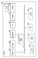
- FIG. 1is a block diagram of an imaging apparatus 100.
- 5is a flowchart showing a reproduction process executed by the imaging apparatus 100.
- FIG. 6is a schematic diagram of thumbnail images displayed on a display unit 107.
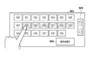
- FIG. 6is a diagram showing a subject selection screen 501.
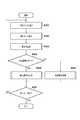
- FIG. 4is a flowchart showing details of still image reproduction processing (S305 in FIG. 3).
- FIG. 4is a flowchart showing details of a moving image reproduction process (S306 in FIG. 3).
- FIG. 6is a schematic diagram of a screen displayed on the display unit 107 during shooting.
- each embodimentwill be described based on an imaging apparatus including a configuration of an image processing apparatus that executes a refocus process during reproduction.
- the image processing apparatus and the imaging apparatusmay be separated.
- the image processing apparatusacquires imaging data and the like from the imaging apparatus, and performs various image processing such as refocus processing based on the acquired imaging data and the like.
- the imaging apparatuscaptures an aperture with pan focus and generates RAW image data as imaging data.
- the imaging apparatuscaptures the subject distance at that position (the position in the depth direction that focuses on the subject, which may be a phase difference or a defocus amount) and the target focal distance ( The image is blurred based on the difference from the focal position. Specifically, image processing is performed to blur the image so that the area corresponding to the target focal position is in focus and the other areas corresponding to positions in the depth direction are blurred according to the depth.
- the effect of the refocus processing on the target in-focus distancecan be obtained in a pseudo manner.
- the method for realizing the refocus processingis not limited to this, and the imaging data generated by the imaging apparatus is not limited to RAW image data obtained from a normal single-lens imaging element.
- the imaging apparatususes the imaging system of Patent Document 1 or an imaging system using a multi-lens imaging device to separate and record light incident from various directions, and has data with light intensity information and angle information. (Light field data) may be generated as imaging data.
- the refocus processingmay be performed by rearranging each pixel data so as to correspond to a desired in-focus distance based on the obtained light field data.
- FIG. 1is a block diagram of an imaging apparatus 100 according to the first embodiment.
- an imaging optical system 101is configured to be able to control a lens in accordance with operations such as zooming and focusing.
- the image sensor 102is configured by a CMOS or the like.
- the image sensor 102is configured to acquire a phase difference signal for AF (autofocus) in units of pixels by dividing and capturing signals of each pixel on the imaging surface. If the phase difference signal output from the image sensor 102 is used, it is possible to acquire distance information of the subject to be photographed.
- the distance information generation unit 111calculates subject distance information based on the phase difference signal output from the image sensor 102 and writes it in the memory 105.
- the image processing unit 103generates digital data by A / D converting the image signal output from the image sensor 102, and generates RAW image data by performing predetermined processing on the digital data.
- the RAW image datais temporarily stored in the memory 105.
- the image processing unit 103performs a development process for display in order to display an image being captured on the display unit 107 such as a liquid crystal panel. Any known technique can be used for generating and developing RAW image data.
- the image processing unit 103performs a refocus process when reproducing RAW image data (details will be described later).
- the memory 105is configured by a DRAM or the like, and holds recording data generated by the recording processing unit 104, a program for controlling the imaging apparatus 100, resource data such as characters and icons displayed on the display unit 107, and the like.
- the recording processing unit 104reads out RAW image data and subject distance information held in the memory 105, converts them into a predetermined recording format, and writes them into the recording medium 108.
- the display processing unit 106performs processing for displaying the video, icons, characters, and the like being captured held in the memory 105 on the display unit 107.
- the display unit 107includes a liquid crystal panel or the like.
- the recording medium 108is a nonvolatile semiconductor memory such as an SD memory card.
- the system control unit 110includes a CPU and the like, and controls the entire imaging apparatus 100.
- a ROM 109read-only memory holds control programs, character fonts, icon resource data, and the like.
- the bus 112is a bus for connecting each unit of the imaging apparatus 100 to exchange data. By transmitting a control signal from the system control unit 110 to each unit of the imaging apparatus 100 via the bus 112, the entire imaging apparatus 100 can be controlled.
- the operation unit 113includes buttons, a dial, and the like, and is used for operation instructions such as recording start and recording stop, and various setting instructions. In addition, the operation unit 113 includes a touch panel mounted on the liquid crystal panel of the display unit 107.
- the system control unit 110detects that a mode setting dial (not shown) of the operation unit 113 is set to the recording mode, the system control unit 110 shifts to the recording mode control.
- the imaging apparatus 100displays the subject image being shot on the display unit 107 so that the user can check the shooting situation.
- the image processing unit 103performs predetermined development processing on the data generated by the image sensor 102 from the subject image incident via the imaging optical system 101 and outputs the data to the memory 105.
- the display processing unit 106converts the data in the memory 105 and displays it on the display unit 107.
- the image to be recorded on the recording medium 108is RAW image data.
- the image processing unit 103generates RAW image data by performing predetermined processing on the data output from the image sensor 102 and temporarily stores it in the memory 105. Thereafter, the recording processing unit 104 converts the RAW image data into a predetermined recording format and records it on the recording medium 108.
- the userdoes not need to distinguish between a moving image and a still image at the time of shooting.
- the imaging apparatus 100receives a recording start instruction from the user via the operation unit 113, the imaging apparatus 100 continuously generates and records RAW image data at a frame rate of 60 fps, for example.
- the system control unit 110performs focusing control so as not to depend on the type of image (moving image or still image). For example, the system control unit 110 reduces the aperture of the imaging optical system 101 to a predetermined setting value so that the focus becomes pan focus, and further acquires RAW image data while controlling the imaging element 102 and the image processing unit 103. .
- imagingmay be performed in a pan-focus state by appropriately adjusting the aperture according to the subject.
- the userselects a still image reproduction mode (first focusing mode) or a moving image reproduction mode (second focusing mode).
- the still image reproduction modeis a reproduction mode for reproducing RAW image data as a still image
- the moving image reproduction modeis a reproduction mode for reproducing RAW image data as a moving image.
- the imaging device 100performs development processing and refocus processing on the RAW image data according to the selected playback mode, and generates a playback image.
- the imaging apparatus 100acquires distance information (details will be described later) of each subject of the RAW image data to be recorded and records it together with the RAW image data.
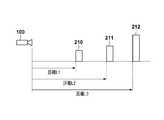
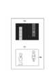
- FIG. 2Ais a schematic diagram showing the arrangement of the imaging device 100 and the subjects 210 to 212.
- the distances from the imaging apparatus 100 to the subjects 210 to 212are distances L1 to L3, respectively.
- the image pickup device 102 of the image pickup apparatus 100is arranged in units of pixels by dividing the light beam from the exit pupil region of the image pickup optical system 101 by the signal of each pixel on the image pickup surface and taking it in by a plurality of photoelectric conversion elements.
- the phase difference signalcan be acquired.
- the distance information generation unit 111generates distance information to the subject being photographed with a predetermined resolution based on the phase difference signal acquired from the image sensor 102. Note that any known technique can be used for generating the distance information by detecting the imaging surface phase difference.
- FIG. 2Bis a schematic diagram of a distance map 215 that represents distance information acquired as a two-dimensional image information when photographing is performed with the arrangement of FIG. 2A.
- the distance map 215represents the numerical value indicating the distance with the shading of the image, and the darker the density, the deeper the subject (the position farther from the imaging device 100).
- the distance data 220 to 222is a density representing the distance to the subjects 210 to 212 in FIG. 2A.
- the density level 230indicates the relationship between the density of the distance map 215 and the distance to the subject.
- the format of the distance informationis not limited to the distance map 215, and any format that indicates at least the distance from the imaging apparatus 100 to each subject in the image can be used.
- the distance in this stateis known.
- the map 215may be stored.
- the defocus map converted into the defocus amount based on the conversion coefficient (K value) based on the light transfer characteristic of the imaging optical system 101may be stored as the distance map 215.
- a distance map of a subject distance obtained by converting the above-described defocus amount into a subject distance based on information such as a lens position of the imaging optical system 101is handled as a distance map 215.
- the resolution of the distance informationis not limited to that shown in FIG. 2B.
- the distance informationonly needs to indicate subject distances (or phase differences, defocus amounts, etc.) at a plurality of positions of the captured image, and the range covered by the distance information at each position is appropriately determined according to the resolution.
- the distance map 215 generated by the distance information generation unit 111is temporarily stored in a predetermined area of the memory 105. Then, the recording processing unit 104 records the distance map 215 held in the memory 105 together with the RAW image data held in the memory 105 under the control of the system control unit 110 on the recording medium 108.
- the RAW image data and the distance map 215are generated based on output signals at the same timing of the image sensor 102. Therefore, when the imaging apparatus 100 generates a plurality of RAW image data, the same number of distance maps 215 as the RAW image data are generated.
- the imaging apparatus 100when the imaging apparatus 100 generates light field data as imaging data, phase difference information can be acquired from the light field data. Therefore, the imaging apparatus 100 does not need to generate distance information at the time of shooting.
- the system control unit 110starts a recording operation when detecting the pressing of a recording button (not shown) of the operation unit 113 in the recording mode.
- the system control unit 110When the recording operation starts, the system control unit 110 generates a file of a predetermined format, sets header information and the like, and then records the file on the recording medium 108.
- the userdoes not need to distinguish between a moving image and a still image at the time of shooting.
- the imaging apparatus 100sequentially generates RAW image data and a distance map 215 at a frame rate of 60 fps and temporarily stores them in the memory 105, and the recording processing unit 104 performs RAW image data and distance map at a predetermined timing. 215 are recorded on the recording medium 108. If there is meta information or the like to be added to the recording frame, the recording processing unit 104 records it on the recording medium 108 at the same time.
- the system control unit 110detects again that the recording button (not shown) of the operation unit 113 is pressed, the system control unit 110 displays the RAW image data and the distance map 215 corresponding to the image signal output from the image sensor 102 at that time. Recording is performed on the recording medium 108. Thereafter, the system control unit 110 stops the recording operation.
- the system control unit 110selects an image file to be played in accordance with a user instruction. For this purpose, the system control unit 110 displays a list of image files recorded on the recording medium 108 on the display unit 107 as thumbnail images. Here, generation of a thumbnail image will be described.
- the system control unit 110reads the image file recorded on the recording medium 108.
- the system control unit 110holds the RAW image data at the head of a series of RAW image data in the read image file in the memory 105.
- the image processing unit 103develops the RAW image data, and further writes a thumbnail image reduced to a predetermined size in the memory 105. Thereafter, the display processing unit 106 displays the thumbnail images held in the memory 105 on the display unit 107.
- FIG. 4is a schematic diagram of thumbnail images displayed on the display unit 107.
- a display screen 401is displayed by a liquid crystal panel to which a touch panel is attached.
- thumbnail images 402 to 407are displayed.
- the userselects an image to be reproduced from the thumbnail images displayed on the display screen 401.
- the userselects the thumbnail image 405 by touching the touch panel.
- the operation unit 113receives a signal from the touch panel, converts this signal into coordinate information on the display screen 401, and outputs it to the system control unit 110.
- the system control unit 110detects the touched thumbnail image based on the coordinate information, and specifies an image file corresponding to the thumbnail image. At this time, the system control unit 110 may highlight the selected thumbnail image on the display screen 401.
- the system control unit 110selects a playback mode according to a user instruction.
- the usertouches and selects either the still image reproduction button 410 or the moving image reproduction button 411 displayed on the display screen 401 in FIG.
- the system control unit 110detects which one of the still image reproduction button 410 and the moving image reproduction button 411 is touched based on the coordinates touched by the user, and determines the reproduction mode.
- the descriptionwill be made assuming that the still image playback mode or the moving image playback mode is selected as the playback mode, but the selectable playback mode is not limited to this. Any configuration in which the playback mode can be selected from two or more playback modes and the focusing control is different depending on the selected playback mode can be included in the present embodiment.
- FIG. 5Ais a schematic diagram of a display screen for the user to select a subject to be focused.
- the system control unit 110reads out RAW image data at a predetermined frame interval from the image file to be reproduced selected in S301. Then, the system control unit 110 develops and generates a thumbnail image in the same procedure as in S301 and displays the thumbnail image on the display unit 107.
- thumbnail images 510 to 513 generated from frames read out from the image file at intervals of 60 frames, that is, at intervals of 1 secondare arranged.
- the usercan check other thumbnail images by touching the left / right button 506 on the touch panel to scroll the screen left and right. .
- the userselects the subject to be focused by touching the subject in the thumbnail image arranged on the subject selection screen 501.
- the subject 580 on the thumbnail image 510is selected.
- the usercan select a subject for each frame by repeating the same operation as described above while scrolling the screen.
- the system control unit 110stores the position information of the selected subject in the memory 105 in association with the frame number.
- the position information and the frame number held hereare also referred to as “refocus data” below.
- the descriptionwill be made assuming that the position of the subject selected by the user is used as a focus target position in the refocus processing, but the present embodiment is not limited to this.
- the imaging apparatus 100can determine the position of the focus target position in the refocus processing based on an arbitrary reference.
- the usercan select a frame to be reproduced from the image file.
- the userpresses the frame selection button 502 in FIG. 5A.
- the system control unit 110displays a frame selection screen 503 shown in FIG. 5B.
- thumbnail images corresponding to the frames in the image file to be reproducedare displayed at intervals of 1 second.
- thumbnail images 520 to 539are displayed.
- the usercan touch the up / down button 505 to scroll the screen up and down to display other thumbnail images.
- the usertouches and selects a frame to be reproduced on the frame selection screen 503.
- thumbnail images 528 to 533are selected.
- a frame in a range corresponding to the thumbnail images 528 to 533is selected as a reproduction target.
- the system control unit 110stores information indicating the selected frame in the memory 105.
- the usercan transition to the subject selection screen 501 in FIG. 5A by pressing the subject selection button 504 on the frame selection screen 503.
- thumbnail imagesare displayed at 60 frame intervals (1 second intervals), but the display intervals of thumbnail images can be arbitrarily changed.
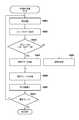
- step S304the system control unit 110 determines whether the still image reproduction mode is selected in step S302. If the still image playback mode is selected, the system control unit 110 advances the process to S305, and if not, the system control unit 110 advances the process to S306. Details of S305 and S306 will be described later.
- the system control unit 110determines whether or not to end the reproduction mode. When the playback mode ends (for example, when the user gives an instruction to end the playback mode using the operation unit 113), the system control unit 110 ends the processing of this flowchart. Otherwise, the system control unit 110 returns the process to S301.
- step S ⁇ b> 601the system control unit 110 reads RAW image data corresponding to the current processing target frame from the playback target image file recorded on the recording medium 108, and stores it in the memory 105.
- the first processing target frameis the first frame of the image file (the first frame of the selected range when a range is selected on the frame selection screen 503 in FIG. 5B).
- the system control unit 110sets development parameters corresponding to still image reproduction in the image processing unit 103 and instructs the image processing unit 103 to perform development processing.
- the system control unit 110stores still image data obtained by the development processing in the memory 105.
- step S ⁇ b> 602the system control unit 110 acquires refocus data from the memory 105.
- step S603the system control unit 110 determines whether there is refocus data corresponding to the current processing target frame. As described in S303, the refocus data includes position information and a frame number. Therefore, the determination in S603 is performed based on a comparison between the frame number of the refocus data and the current processing target frame number. If there is refocus data corresponding to the current processing target frame, the system control unit 110 advances the process to step S604. If there is no refocus data corresponding to the current processing target frame, the system control unit 110 advances the process to step S605.
- step S ⁇ b> 604the system control unit 110 extracts subject image data (subject data) in the position information included in the refocus data from the still image data generated in step S ⁇ b> 601 and stores it in the memory 105. This subject data is used for subject tracking processing in S605.
- step S605the system control unit 110 performs subject tracking processing. Specifically, the system control unit 110 acquires subject data stored in the memory 105 in S604. Then, the system control unit 110 detects the position of the subject by searching for a subject image corresponding to the subject data in the processing target frame image by matching processing or edge detection. Further, the system control unit 110 updates the subject data in the memory 105 with the detected subject image data. As a result, the refocus processing based on the subject can be performed even for frames in which no corresponding refocus data exists (imaging data other than the imaging data in which the refocus data exists).
- the subject tracking methodis not limited to the above, and any known technique can be used.
- the system control unit 110may fail to detect the position of the subject, such as when the subject to be focused out of frame. In this case, the system control unit 110 detects the position of the subject using subject data older than the latest subject data stored in the memory 105 (that is, subject data of a frame before the immediately preceding frame). . In order to enable such detection processing to be retried, the system control unit 110 deletes old subject data when storing subject data in the memory 105 in step S604 or updating subject data in step S605. Leave without. Further, the imaging apparatus 100 may be configured to delete subject data older than a predetermined number of frames.
- FIG. 7is a conceptual diagram of still image refocus processing.
- the imaging apparatus 100performs still image refocus processing based on the recorded RAW image data and a distance map corresponding to the RAW image data.
- the system control unit 110reads a distance map corresponding to the frame number to be processed from the recording medium 108 and stores it in the memory 105. The determination of the in-focus distance is performed using a distance map stored in the memory 105.
- the shading level of each regionrepresents the distance.
- An image 701 in FIG. 7represents an image corresponding to the distance map 700.
- a subject area 702indicates the position of the subject to be focused. This position corresponds to the position information included in the refocus data or the position detected by the tracking process in S605.
- the image processing unit 103acquires distance data corresponding to the coordinates of the subject area 702 from the distance map 700. In the distance map 700 of FIG. 7, since the distance data corresponding to the subject area 702 corresponds to the area “A”, the image processing unit 103 acquires the distance data of the area “A”.
- the image processing unit 103calculates the difference “dk” from the distance data of each region of the distance map 700 by using the acquired distance data as “k”. Then, the image processing unit 103 uses the value n calculated by multiplying the difference “dk” by a predetermined coefficient to generate a kernel of the coefficient p with a size of n ⁇ n. Then, the image processing unit 103 performs a convolution operation with the still image generated in S601 using the kernel generated for each region of the distance map 700, and blurs the image. As a result, a refocus image in which the amount of blurring of the image changes according to the difference from the distance data of the subject region 702 can be obtained. Note that the refocus processing is not limited to the above-described processing, and any known technique can be used.
- the subject selected by the useris focused and a refocus image blurred according to the distance difference from the subject in the depth direction is generated.
- the generated refocus imageis stored in the memory 105.
- the system control unit 110displays the refocused image held in the memory 105 on the display unit 107 as a reproduction image.
- the reproduction imageis displayed for each sheet.
- the reproduced imagetransitions to the next image.
- the reproduced imagecan be reduced and displayed on the display unit 107 for each of a plurality of images.
- the system control unit 110determines whether or not the last frame of the frames to be played has been reached. When the final frame is reached, the system control unit 110 returns the processing to the flowchart of FIG. If the final frame has not been reached, the system control unit 110 returns the process to S601 and performs the same process using the next frame as the frame to be processed.
- focused refocus imagesare sequentially generated and displayed in units of frames while tracking the subject of the frame held in the refocus data.
- step S ⁇ b> 801the system control unit 110 reads RAW image data corresponding to the current processing target frame from the playback target image file recorded on the recording medium 108, and stores it in the memory 105.
- the first processing target frameis the first frame of the image file (the first frame of the selected range when a range is selected on the frame selection screen 503 in FIG. 5B).
- the system control unit 110sets development parameters corresponding to moving image reproduction in the image processing unit 103 and instructs the image processing unit 103 to perform development processing.
- the system control unit 110stores the moving image data obtained by the development processing in the memory 105.
- step S806the system control unit 110 performs moving image refocus processing.
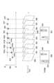
- the upper part of FIG. 9schematically shows the variation of the focus distance
- the middle part of FIG. 9schematically shows the frame to be reproduced.
- Frames 920 to 928are arranged in the order of generation and are played back at a frame rate of 60 fps.
- the lower part of FIG. 9schematically shows a refocus image when the frames 920 and 925 are displayed on the display unit 107.
- the method for determining the focus distanceis different from that in the still image reproduction process. Since the continuity of images between frames affects the image quality in a moving image, the imaging apparatus 100 limits the fluctuation speed of the focus distance to a threshold value or less.
- the system control unit 110reads a distance map corresponding to the frame 921 from the recording medium 108 and stores it in the memory 105.
- the system control unit 110detects the distance 911b of the subject 933 in the frame 921 based on the distance map.
- the system control unit 110determines the focus distance as the distance 911a so that the focus distance follows the subject 933 at a speed equal to or less than the threshold. Then, the system control unit 110 generates a refocus image so as to focus on the distance 911a.
- a specific generation methodis the same as S607 in FIG.
- the subject distanceis the distance 912b to 914b, but as a result of limiting the speed to the threshold value or less, a refocus image having the distance 912a to 914a as the in-focus distance is generated.
- the frames 925 to 928since the difference between the subject distance of the frame to be processed and the focus distance of the immediately preceding frame is small, a refocus image with the distances 915 to 918 matching the subject distance as the focus distance is generated. The Accordingly, the refocus image 931 is focused on the subject 933.
- the refocus processing described abovegenerates a refocus image that follows the subject selected by the user over a plurality of frames at a speed equal to or less than a threshold.
- the generated refocus imageis stored in the memory 105.
- the imaging apparatus 100may be configured so that the user can determine the threshold value. For example, the imaging apparatus 100 displays a threshold value determination screen on the display unit 107, and the user instructs a desired threshold value on the threshold value determination screen. The system control unit 110 determines a threshold according to a user instruction on the threshold determination screen.
- the system control unit 110displays the refocus image held in the memory 105 on the display unit 107 as a reproduction image.
- the playback imageautomatically transitions to the next image according to the playback frame rate (for example, 60 fps). Therefore, the system control unit 110 automatically advances the processing to S608 after displaying the reproduction image, and displays the reproduction image one after another according to the reproduction frame rate.
- the imaging device 100performs a refocus process and generates a reproduced image when reproducing the imaging data.
- the imaging apparatus 100determines the focus distance for the refocus process according to the selected playback mode. Thereby, it is possible to execute the focusing control according to the application of the image.
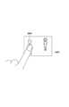
- FIG. 10is a schematic diagram of a screen displayed on the display unit 107 during shooting.
- An image 1001is an image acquired by the imaging device 100 via the imaging element 102 during shooting.
- the usercan select a subject to be focused by a touch operation during shooting. In the example of FIG. 10, it is assumed that the user touches the subject 1002.
- the operation unit 113receives a signal from the touch panel, converts this signal into coordinates on the display screen, and outputs the signal to the system control unit 110.
- the system control unit 110records the position information indicating the coordinates and the current frame number on the recording medium 108 as refocus data.
- the system control unit 110tracks the subject, detects the position of the subject, and records the refocus data on the recording medium 108.
- the system control unit 110may generate the refocus data only for the frame at the timing when the user touches without tracking the subject.
- the refocus datais recorded, for example, in the header portion of the image file.
- Reproduction processingis the same as that of the first embodiment except S303 in FIG.
- the system control unit 110detects that the refocus data is included in the header portion of the image file to be reproduced. In response to this detection, the system control unit 110 displays a message for confirming whether to use the refocus data of the image file on the display unit 107. The user selects whether to use the refocus data of the image file via the operation unit 113. When the user uses the refocus data of the image file, the system control unit 110 performs the processes after S304 using the refocus data of the image file.
- the imaging apparatus 100performs the refocus processing based on the difference between the subject distance and the focusing distance at each position of the captured image.
- the imaging apparatus 100according to the present embodiment performs refocus processing using the lens design data of the imaging optical system 101.
- the imaging apparatus 100uses the image processing unit 103 to calculate the blur amount of a subject located at a distance other than the in-focus distance based on the lens design data during the refocus processing, and refocus the image. Is generated. Any known technique can be used as the technique for calculating the blur amount from the lens design data.
- the imaging apparatus 100determines the threshold value of the fluctuation speed of the focus distance in the moving image reproduction process (see FIGS. 8 and 9) based on the lens design data.
- the imaging apparatus 100generates the refocus data used at the time of reproduction according to the user's subject selection at the time of shooting. This makes it possible to generate a refocus image reflecting the situation at the time of shooting.
- the imaging apparatus 100since the imaging apparatus 100 performs the refocus processing using the lens design data, it is possible to obtain an image quality closer to optical focus control.
- the present inventionsupplies a program that realizes one or more functions of the above-described embodiments to a system or apparatus via a network or a storage medium, and one or more processors in a computer of the system or apparatus read and execute the program This process can be realized. It can also be realized by a circuit (for example, ASIC) that realizes one or more functions.
- a circuitfor example, ASIC
- DESCRIPTION OF SYMBOLS 100... Imaging device, 101 ... Imaging optical system, 102 ... Image sensor, 103 ... Image processing part, 104 ... Recording processing part, 105 ... Memory, 106 ... Display processing part, 107 ... Display part, 108 ... Recording medium, 109 ... ROM, 110 ... system control unit, 111 ... distance information generation unit
Landscapes
- Engineering & Computer Science (AREA)
- Multimedia (AREA)
- Signal Processing (AREA)
- Physics & Mathematics (AREA)
- Human Computer Interaction (AREA)
- General Physics & Mathematics (AREA)
- Optics & Photonics (AREA)
- Studio Devices (AREA)
- Focusing (AREA)
- Automatic Focus Adjustment (AREA)
Abstract
Description
Translated fromJapanese本発明は、画像処理装置、撮像装置、画像処理方法、及びプログラムに関する。The present invention relates to an image processing device, an imaging device, an image processing method, and a program.
近年、デジタルカメラ等の撮像装置において、撮影後に任意の被写体に合焦した画像を生成する技術が提案されている(特許文献1参照)。特許文献1の撮像装置は、マイクロレンズアレイを介して撮像素子の各画素に撮像光学系の異なる瞳領域を通過した光束を結像させることにより、様々な方向から入射した光を分離して記録した動画出力データを生成する。その後、撮像装置は、動画記録データから、特定の被写体に合焦した動画を生成する。In recent years, a technique for generating an image focused on an arbitrary subject after shooting in an imaging apparatus such as a digital camera has been proposed (see Patent Document 1). The imaging apparatus of Patent Document 1 separates and records light incident from various directions by forming a light beam that has passed through different pupil regions of the imaging optical system on each pixel of the imaging element via a microlens array. Generated video output data. Thereafter, the imaging device generates a moving image focused on a specific subject from the moving image recording data.
静止画と動画とでは、高画質な画像を得るのに適した合焦制御が異なる。静止画の場合、被写体に正確に合焦させることが、画質の向上につながる。他方、動画の場合、時間方向の連続性が画質に影響を与える。そのため、被写体が高速に移動した場合、追従速度を抑制して徐々に被写体に合焦させることが、画質の向上につながる。The focus control suitable for obtaining high-quality images differs between still images and moving images. In the case of a still image, accurately focusing on the subject leads to an improvement in image quality. On the other hand, in the case of moving images, continuity in the time direction affects the image quality. Therefore, when the subject moves at a high speed, suppressing the tracking speed and gradually focusing on the subject leads to an improvement in image quality.
しかしながら、特許文献1は、動画を生成することは開示しているが、動画記録データの各フレームから静止画を生成することは考慮していない。動画出力データの用途に応じた合焦制御を撮影後に行う技術はこれまで提案されていなかった。However, Patent Document 1 discloses generating a moving image, but does not consider generating a still image from each frame of moving image recording data. Until now, no technique has been proposed for performing focusing control according to the use of moving image output data after shooting.
本発明はこのような状況に鑑みてなされたものであり、撮像データから画像を生成する際に、画像の用途に応じた合焦制御を実行することを可能にする技術を提供する。The present invention has been made in view of such a situation, and provides a technique that makes it possible to execute focusing control in accordance with the use of an image when generating an image from captured data.
本発明の第1の態様は、撮像手段により連続的に生成された複数の撮像データを取得する取得手段と、前記複数の撮像データそれぞれについて各撮像データの画像内の対象位置を決定する対象位置決定手段と、第1の合焦モード又は第2の合焦モードを選択する選択手段と、前記複数の撮像データそれぞれについて、前記対象位置における奥行き方向の焦点位置を決定する焦点位置決定手段と、前記複数の撮像データそれぞれについて、前記決定された焦点位置でピントが合い、他の位置でぼけている画像を前記撮像データから生成する生成手段と、を備え、前記焦点位置決定手段は、前記選択手段により前記第1の合焦モードが選択された場合、前記対象位置における被写体の合焦する位置を前記焦点位置として決定し、前記選択手段により前記第2の合焦モードが選択された場合、前記複数の撮像データそれぞれの焦点位置が、前記複数の撮像データの生成順において閾値以下の速度で、前記対象位置における被写体の合焦する位置に追従するように前記焦点位置の決定を行うことを特徴とする画像処理装置を提供する。According to a first aspect of the present invention, an acquisition unit that acquires a plurality of imaging data continuously generated by an imaging unit, and a target position that determines a target position in an image of each imaging data for each of the plurality of imaging data A determining unit; a selecting unit that selects the first focusing mode or the second focusing mode; a focal position determining unit that determines a focal position in the depth direction at the target position for each of the plurality of imaging data; Generating means for generating, from the imaging data, an image that is in focus at the determined focal position and blurred at another position for each of the plurality of imaging data, and the focal position determination means includes the selection When the first focusing mode is selected by the means, the focus position of the subject at the target position is determined as the focal position, and the selection means When the second focusing mode is selected, the focus position of each of the plurality of imaging data is a position at which the subject is focused at the target position at a speed equal to or lower than a threshold in the order of generation of the plurality of imaging data. An image processing apparatus is characterized in that the focal position is determined so as to follow.
本発明の第2の態様は、画像処理装置が実行する画像処理方法であって、撮像手段により連続的に生成された複数の撮像データを取得する取得工程と、前記複数の撮像データそれぞれについて各撮像データの画像内の対象位置を決定する対象位置決定工程と、第1の合焦モード又は第2の合焦モードを選択する選択工程と、前記複数の撮像データそれぞれについて、前記対象位置における奥行き方向の焦点位置を決定する焦点位置決定工程と、前記複数の撮像データそれぞれについて、前記決定された焦点位置でピントが合い、他の位置でぼけている画像を前記撮像データから生成する生成工程と、を備え、前記焦点位置決定工程では、前記選択工程により前記第1の合焦モードが選択された場合、前記対象位置における被写体の合焦する位置を前記焦点位置として決定し、前記選択工程により前記第2の合焦モードが選択された場合、前記複数の撮像データそれぞれの焦点位置が、前記複数の撮像データの生成順において閾値以下の速度で、前記対象位置における被写体の合焦する位置に追従するように前記焦点位置の決定を行うことを特徴とする画像処理方法を提供する。According to a second aspect of the present invention, there is provided an image processing method executed by an image processing apparatus, wherein an acquisition step of acquiring a plurality of imaging data continuously generated by an imaging unit, and each of the plurality of imaging data A target position determining step for determining a target position in the image of the imaging data, a selection step for selecting the first focusing mode or the second focusing mode, and the depth at the target position for each of the plurality of imaging data. A focal position determination step for determining a focal position in a direction, and a generation step for generating an image that is in focus at the determined focal position and blurred at another position from the imaging data for each of the plurality of imaging data. In the focal position determination step, when the first focusing mode is selected in the selection step, the subject at the target position is focused. When the second focus mode is selected in the selection step, the focus position of each of the plurality of imaging data is a speed equal to or lower than a threshold in the order of generation of the plurality of imaging data. Thus, the image processing method is characterized in that the focal position is determined so as to follow the position where the subject is focused at the target position.
本発明によれば、撮像データから画像を生成する際に、画像の用途に応じた合焦制御を実行することが可能となる。According to the present invention, when an image is generated from imaging data, it is possible to execute focusing control according to the application of the image.
本発明のその他の特徴及び利点は、添付図面を参照とした以下の説明により明らかになるであろう。なお、添付図面においては、同じ若しくは同様の構成には、同じ参照番号を付す。Other features and advantages of the present invention will become apparent from the following description with reference to the accompanying drawings. In the accompanying drawings, the same or similar components are denoted by the same reference numerals.
添付図面は明細書に含まれ、その一部を構成し、本発明の実施の形態を示し、その記述と共に本発明の原理を説明するために用いられる。
以下、添付図面を参照して、本発明の実施形態を説明する。なお、本発明の技術的範囲は、特許請求の範囲によって確定されるのであって、以下の個別の実施形態によって限定されるわけではない。また、実施形態の中で説明されている特徴の組み合わせすべてが、本発明に必須とは限らない。Hereinafter, embodiments of the present invention will be described with reference to the accompanying drawings. The technical scope of the present invention is determined by the claims, and is not limited by the following individual embodiments. In addition, not all combinations of features described in the embodiments are essential to the present invention.
なお、以下では、再生時にリフォーカス処理を実行する画像処理装置の構成を含んだ撮像装置に基づいて、各実施形態の説明を行う。しかしながら、画像処理装置と撮像装置とは分離していてもよい。この場合、画像処理装置は、撮像装置から撮像データなどを取得し、取得した撮像データなどに基づいてリフォーカス処理などの各種画像処理を行う。In the following, each embodiment will be described based on an imaging apparatus including a configuration of an image processing apparatus that executes a refocus process during reproduction. However, the image processing apparatus and the imaging apparatus may be separated. In this case, the image processing apparatus acquires imaging data and the like from the imaging apparatus, and performs various image processing such as refocus processing based on the acquired imaging data and the like.
また、以下の各実施形態では、再生時のリフォーカス処理を可能にするために、撮像装置は絞りをパンフォーカスで撮影を行い、撮像データとしてRAW画像データを生成するものとする。撮像装置は、パンフォーカスの撮像画像の各位置に対して、その位置の被写体距離(被写体に合焦する奥行き方向の位置であり、位相差やデフォーカス量でもよい)と目標の合焦距離(焦点位置)との差に基づいて画像にぼかし処理を行う。具体的には、目標の焦点位置に対応する領域ではピントが合った合焦状態で、その他の奥行き方向の位置に対応する領域は奥行きに応じてぼけているように画像をぼかす画像処理を行うことにより、目標の合焦距離に対するリフォーカス処理の効果を擬似的に得ることができる。このとき、予め被写界深度にあたるピントのある奥行き方向の範囲を設定できるようにしておいてもよい。また、リフォーカス処理の実現方法はこれに限定されず、撮像装置が生成する撮像データは通常の一眼の撮像素子から得られるRAW画像データに限定されない。例えば、撮像装置は、特許文献1の撮像系や多眼の撮像素子を用いた撮像系などによって、様々な方向から入射した光を分離して記録した、光線の強度情報と角度情報を持つデータ(ライトフィールドデータ)を撮像データとして生成するものでもよい。このとき、得られるライトフィールドデータに基づいて所望の合焦距離に対応するように各画素データを並び替えるなどしてリフォーカス処理を行ってもよい。In each of the following embodiments, in order to enable refocus processing at the time of reproduction, the imaging apparatus captures an aperture with pan focus and generates RAW image data as imaging data. For each position of the pan-focus captured image, the imaging apparatus captures the subject distance at that position (the position in the depth direction that focuses on the subject, which may be a phase difference or a defocus amount) and the target focal distance ( The image is blurred based on the difference from the focal position. Specifically, image processing is performed to blur the image so that the area corresponding to the target focal position is in focus and the other areas corresponding to positions in the depth direction are blurred according to the depth. As a result, the effect of the refocus processing on the target in-focus distance can be obtained in a pseudo manner. At this time, a range in the depth direction with focus corresponding to the depth of field may be set in advance. In addition, the method for realizing the refocus processing is not limited to this, and the imaging data generated by the imaging apparatus is not limited to RAW image data obtained from a normal single-lens imaging element. For example, the imaging apparatus uses the imaging system of Patent Document 1 or an imaging system using a multi-lens imaging device to separate and record light incident from various directions, and has data with light intensity information and angle information. (Light field data) may be generated as imaging data. At this time, the refocus processing may be performed by rearranging each pixel data so as to correspond to a desired in-focus distance based on the obtained light field data.
[第1の実施形態]
図1は、第1の実施形態に係る撮像装置100のブロック図である。図1において、撮像光学系101は、ズーム、フォーカス等の操作に応じてレンズ制御できるように構成されている。撮像素子102は、CMOS等により構成される。撮像素子102は、撮像面の各画素の信号を分割して取り込むことにより画素単位でAF(オートフォーカス)用の位相差信号を取得できるように構成されている。撮像素子102から出力される位相差信号を用いれば、撮影する被写体の距離情報を取得することができる。距離情報生成部111は、撮像素子102から出力される位相差信号をもとに、被写体の距離情報を算出して、メモリ105に書き込む。[First Embodiment]
FIG. 1 is a block diagram of an
画像処理部103は、撮像素子102から出力される画像信号をA/D変換することによりデジタルデータを生成し、このデジタルデータに対して所定の処理を施すことによりRAW画像データを生成する。RAW画像データは、メモリ105に一時的に保持される。また、記録モード時においては、画像処理部103は、撮影中の映像を液晶パネル等の表示部107に表示するために、表示用の現像処理を行う。RAW画像データの生成及び現像処理には、任意の既知の技術を利用可能である。また、画像処理部103は、RAW画像データの再生時にリフォーカス処理を行う(詳細は後述)。The
メモリ105は、DRAM等により構成され、記録処理部104で生成される記録データ、撮像装置100を制御するプログラム、及び、表示部107に表示する文字やアイコン等のリソースデータ等を保持する。The
記録処理部104は、メモリ105に保持されているRAW画像データ及び被写体の距離情報を読み出して所定の記録フォーマットに変換し、記録媒体108に書きこむ。表示処理部106は、メモリ105に保持されている撮影中の映像、アイコン、及び文字などを表示部107に表示する処理を行う。表示部107は、液晶パネル等から構成される。記録媒体108は、SDメモリカード等の不揮発性半導体メモリである。The
システム制御部110は、CPU等から構成され、撮像装置100全体を制御する。ROM109(リードオンリーメモリ)は、制御プログラム、文字フォント、アイコンリソースデータ等を保持する。バス112は、撮像装置100の各部を接続してデータ交換を行うためのバスである。システム制御部110からの制御信号をバス112を介して撮像装置100の各部に伝達することで、撮像装置100全体を制御することができる。操作部113は、ボタン及びダイヤル等を含み、記録開始及び記録停止等の動作指示や、各種設定指示のために用いられる。また、表示部107の液晶パネル上に装着されているタッチパネルも操作部113に含まれるものとする。The
ここで、本実施形態に係る撮像装置100の記録動作について説明する。システム制御部110は、操作部113の不図示のモード設定ダイヤルが記録モードに設定されたことを検出すると、記録モードの制御に移行する。記録モードにおいては、撮像装置100は、ユーザが撮影状況を確認できるようにするために、撮影中の被写体像を表示部107に表示する。そのために、画像処理部103は、撮像光学系101を介して入射した被写体像から撮像素子102が生成したデータに対して、所定の現像処理を行い、メモリ105に出力する。表示処理部106は、メモリ105のデータを変換して表示部107に表示する。また、本実施形態では、記録媒体108に記録する画像はRAW画像データであるものとする。そこで、画像処理部103は、撮像素子102から出力されるデータに対して所定の処理を施すことによりRAW画像データを生成し、メモリ105に一時的に格納する。その後、記録処理部104は、RAW画像データを所定の記録フォーマットに変換して記録媒体108に記録する。Here, the recording operation of the
また、本実施形態では、ユーザは、撮影時には動画と静止画とを区別する必要が無い。撮像装置100は、操作部113を介してユーザから記録開始指示を受信すると、例えば60fpsのフレームレートでRAW画像データを連続的に生成して記録する。撮影中、システム制御部110は、画像の種類(動画又は静止画)に依存しないように合焦制御を行う。例えば、システム制御部110は、フォーカスがパンフォーカスとなるように撮像光学系101の絞りを所定の設定値に絞り、更に、撮像素子102及び画像処理部103を制御しながらRAW画像データを取得する。なお、被写体に応じて適宜絞りを調節してパンフォーカス状態で撮像してもよい。RAW画像データの再生時に、ユーザは、静止画再生モード(第1の合焦モード)又は動画再生モード(第2の合焦モード)を選択する。静止画再生モードは、RAW画像データを静止画として再生する再生モードであり、動画再生モードは、RAW画像データを動画として再生する再生モードである。撮像装置100は、RAW画像データに対して、選択された再生モードに応じた現像処理及びリフォーカス処理を行い、再生画像を生成する。再生時のリフォーカス処理を可能にするために、撮像装置100は、記録するRAW画像データの各被写体の距離情報(詳細は後述)を取得し、RAW画像データと共に記録する。In this embodiment, the user does not need to distinguish between a moving image and a still image at the time of shooting. When the
次に、図2A及び図2Bを参照して、被写体の距離情報について説明する。図2Aは、撮像装置100及び被写体210~212の配置を示す概略図である。撮像装置100から被写体210~212までの距離は、各々距離L1~L3である。前述の通り、撮像装置100の撮像素子102は、撮像面の各画素の信号を撮像光学系101の射出瞳領域からの光束を分割して複数の光電変換素子で取り込むことにより、画素単位で位相差信号を取得できるように構成されている。距離情報生成部111は、撮像素子102から取得した位相差信号をもとに、撮影している被写体までの距離情報を所定の分解能で生成する。なお、撮像面位相差検出による距離情報の生成については、任意の既知の技術を用いることができる。Next, the distance information of the subject will be described with reference to FIGS. 2A and 2B. FIG. 2A is a schematic diagram showing the arrangement of the
図2Bは、図2Aの配置で撮影を行った場合に取得される距離情報を2次元の画像情報として表した距離マップ215の模式図である。距離マップ215は、距離を示す数値を画像の濃淡で表しており、濃度が濃いほど被写体が奥(撮像装置100から遠い位置)にあることを示している。距離データ220~222は、図2Aの被写体210~212までの距離を表す濃度である。濃度レベル230は、距離マップ215の濃度と被写体までの距離との関係を示すものである。FIG. 2B is a schematic diagram of a
なお、距離情報の形式は距離マップ215に限られるものではなく、撮像装置100からの画像内の各被写体までの距離を少なくとも相対的に示す任意の形式を用いることが可能である。例えば、撮像素子102から取得した位相差信号に基づき、位相差(光電変換素子からの像信号間の像ずれ)マップを求めた段階で領域毎の距離の相対関係はわかるため、この状態で距離マップ215として記憶しておいてもよい。また、位相差マップを撮像光学系101の光伝達特性に基づく変換係数(K値)に基づき、デフォーカス量に換算したデフォーカスマップを距離マップ215として記憶しておいてもよい。本実施形態では、前述したデフォーカス量をさらに撮像光学系101のレンズ位置などの情報に基づいて被写体距離に換算した被写体距離の距離マップを距離マップ215として扱う。また、距離情報の分解能も、図2Bに示されるものに限定されない。距離情報は、撮像画像の複数の位置における被写体距離(あるいは位相差、デフォーカス量など)を示していればよく、分解能に応じて、各位置における距離情報がカバーする範囲が適宜決定される。It should be noted that the format of the distance information is not limited to the
距離情報生成部111が生成した距離マップ215は、メモリ105の所定の領域に一時的に保持される。そして、記録処理部104は、システム制御部110の制御に従い、メモリ105に保持されている距離マップ215を、メモリ105に保持されているRAW画像データと共に、記録媒体108に記録する。RAW画像データと距離マップ215とは、撮像素子102の同じタイミングの出力信号を基に生成される。従って、撮像装置100が複数のRAW画像データを生成する場合、距離マップ215も、RAW画像データと同じ数だけ生成される。The
なお、撮像装置100が撮像データとしてライトフィールドデータを生成する場合は、ライトフィールドデータから位相差情報を取得可能である。そのため、撮像装置100は、撮影時に距離情報を生成する必要は無い。Note that when the
本実施形態では、システム制御部110は、記録モードにおいて操作部113の記録ボタン(不図示)の押下を検知すると、記録動作を開始する。記録動作が開始すると、システム制御部110は、所定のフォーマットのファイルを生成して、ヘッダ情報等を設定した後に、記録媒体108に記録する。前述の通り、本実施形態では、ユーザは、撮影時には動画と静止画とを区別する必要が無い。記録中は、撮像装置100は、フレームレート60fpsで逐次RAW画像データと距離マップ215とを生成して一時的にメモリ105に格納し、記録処理部104が所定のタイミングでRAW画像データと距離マップ215とを記録媒体108に記録する。記録フレームに付加すべきメタ情報等があれば、記録処理部104は、同時に記録媒体108に記録する。In the present embodiment, the
ここで、システム制御部110は、操作部113の記録ボタン(不図示)の押下を再度検知すると、その時点での撮像素子102から出力される画像信号に対応したRAW画像データ及び距離マップ215を記録媒体108に記録する。その後、システム制御部110は、記録動作を停止する。Here, when the
次に、図3のフローチャートを参照して、撮像装置100が実行する再生処理について説明する。本フローチャートの各ステップの処理は、特に断らない限り、システム制御部110が制御プログラムを実行して撮像装置100の各部を制御することにより実現される。システム制御部110が操作部113を介してユーザから再生指示を受信すると、本フローチャートの処理が開始する。Next, a reproduction process executed by the
S301で、システム制御部110は、ユーザ指示に従い、再生対象の画像ファイルを選択する。そのために、システム制御部110は、表示部107に、記録媒体108に記録されている画像ファイルの一覧をサムネイル画像として表示する。ここで、サムネイル画像の生成について説明する。システム制御部110は、記録媒体108に記録されている画像ファイルを読み出す。システム制御部110は、読み出した画像ファイル内の一連のRAW画像データの先頭のRAW画像データをメモリ105に保持する。次に、画像処理部103は、RAW画像データを現像処理し、更に、所定のサイズに縮小したサムネイル画像をメモリ105に書き出す。その後、表示処理部106は、メモリ105に保持されているサムネイル画像を表示部107に表示する。In S301, the
図4は、表示部107に表示されるサムネイル画像の模式図である。図4において、表示画面401は、タッチパネルを貼付した液晶パネルにより表示される。表示画面401には、サムネイル画像402~407が表示されている。FIG. 4 is a schematic diagram of thumbnail images displayed on the
ユーザは、表示画面401に表示されたサムネイル画像の中から、再生対象の画像を選択する。図4の例では、ユーザは、タッチパネルをタッチすることにより、サムネイル画像405を選択している。操作部113は、タッチパネルからの信号を受け取り、この信号を表示画面401上の座標情報に変換して、システム制御部110に出力する。システム制御部110は、座標情報をもとに、タッチされているサムネイル画像を検出して、そのサムネイル画像に対応する画像ファイルを特定する。この時、システム制御部110は、表示画面401において、選択されたサムネイル画像を強調表示してもよい。The user selects an image to be reproduced from the thumbnail images displayed on the
次に、S302で、システム制御部110は、ユーザ指示に従い、再生モードを選択する。ユーザは、図4の表示画面401に表示される静止画再生ボタン410及び動画再生ボタン411のいずれかをタッチして選択する。システム制御部110は、ユーザがタッチした座標をもとに、静止画再生ボタン410及び動画再生ボタン411のいずれがタッチされたかを検出し、再生モードを決定する。なお、本実施形態では、再生モードとして静止画再生モード又は動画再生モードが選択されるものとして説明を行うが、選択可能な再生モードはこれに限定されない。2以上の再生モードから再生モードを選択可能であり、選択された再生モードに応じて合焦制御が異なるあらゆる構成が、本実施形態に含まれ得る。Next, in S302, the
S303で、システム制御部110は、ユーザ指示に従い、合焦対象とする被写体を選択する。図5Aは、ユーザが合焦対象の被写体を選択するための表示画面の模式図である。システム制御部110は、S301において選択した再生対象の画像ファイルから所定のフレーム間隔でRAW画像データを読み出す。そして、システム制御部110は、S301と同様の手順で現像及びサムネイル画像の生成を行い、表示部107に表示する。図5Aの被写体選択画面501には、画像ファイルから60フレーム間隔、即ち1秒間隔で読み出したフレームから生成したサムネイル画像510~513が配置されている。被写体選択画面501の中に全てのサムネイル画像が収まらない場合には、ユーザは、タッチパネル上で左右ボタン506をタッチすることにより、画面を左右にスクロースして他のサムネイル画像を確認することができる。ユーザは、被写体選択画面501に配置されているサムネイル画像内の被写体をタッチすることで、合焦対象の被写体を選択する。図5Aの例では、サムネイル画像510上の被写体580が選択されている。ユーザは、画面をスクロールしながら上記と同様の操作を繰り返すことで、フレーム毎に被写体を選択することができる。システム制御部110は、選択された被写体の位置情報を、フレーム番号に関連付けてメモリ105に保持する。ここで保持される位置情報及びフレーム番号を、以下では「リフォーカスデータ」とも呼ぶ。In S303, the
なお、本実施形態では、ユーザが選択した被写体の位置がリフォーカス処理における合焦の対象位置として用いられるものとして説明を行うが、本実施形態はこれに限定されない。撮像装置100は、リフォーカス処理における合焦の対象位置の位置決定を、任意の基準で行うことができる。In the present embodiment, the description will be made assuming that the position of the subject selected by the user is used as a focus target position in the refocus processing, but the present embodiment is not limited to this. The
また、S303において、ユーザは、画像ファイルの中で再生対象とするフレームを選択することができる。ユーザは、図5Aのフレーム選択ボタン502を押下する。システム制御部110は、この押下を検出すると、図5Bに示すフレーム選択画面503を表示する。フレーム選択画面503には、再生対象の画像ファイル内のフレームに対応するサムネイル画像が1秒間隔で表示される。ここでは、サムネイル画像520~539が表示されている。フレーム選択画面503の中に全てのサムネイル画像が収まらない場合には、ユーザは、上下ボタン505をタッチすることにより、画面を上下にスクロースして他のサムネイル画像を表示させることができる。ユーザは、フレーム選択画面503において、再生対象とするフレームをタッチして選択する。図5Bの例では、サムネイル画像528~533が選択されている。この場合、サムネイル画像528~533に対応する範囲のフレームが再生対象として選択される。システム制御部110は、選択したフレームを示す情報をメモリ105に格納する。また、ユーザは、フレーム選択画面503の被写体選択ボタン504を押下することで、図5Aの被写体選択画面501に遷移することができる。In S303, the user can select a frame to be reproduced from the image file. The user presses the
なお、フレーム選択画面503における選択が行われない場合、画像ファイル内の全てのフレームが再生対象となる。また、図5A及び図5Bの例では、60フレーム間隔(1秒間隔)でサムネイル画像が表示されているが、サムネイル画像の表示間隔は任意に変更することが可能である。If no selection is made on the
ユーザが被写体選択画面501の再生ボタン507をタッチすると、システム制御部110は処理をS304に進める。S304で、システム制御部110は、S302において静止画再生モードが選択されたか否かを判定する。静止画再生モードが選択された場合、システム制御部110は処理をS305に進め、そうでない場合、システム制御部110は処理をS306に進める。S305及びS306の詳細については後述する。When the user touches the
S307で、システム制御部110は、再生モードを終了するか否かを判定する。再生モードを終了する場合(例えば、ユーザが操作部113により再生モードの終了指示を行った場合)、システム制御部110は本フローチャートの処理を終了する。そうでない場合、システム制御部110は処理をS301に戻す。In S307, the
図6を参照して、S305の静止画再生処理について説明する。S601で、システム制御部110は、記録媒体108に記録されている再生対象の画像ファイルから、現在の処理対象のフレームに対応するRAW画像データを読み出し、メモリ105に格納する。最初の処理対象のフレームは、画像ファイルの先頭フレーム(図5Bのフレーム選択画面503において範囲の選択が行われた場合、選択範囲の先頭フレーム)である。また、システム制御部110は、画像処理部103に、静止画再生に対応した現像パラメータを設定し、画像処理部103に現像処理を指示する。システム制御部110は、現像処理により得られた静止画データをメモリ105に格納する。Referring to FIG. 6, the still image reproduction process in S305 will be described. In step S <b> 601, the
S602で、システム制御部110は、メモリ105からリフォーカスデータを取得する。S603で、システム制御部110は、現在の処理対象のフレームに対応するリフォーカスデータが存在するか否かを判定する。S303において説明した通り、リフォーカスデータは位置情報及びフレーム番号を含む。そのため、S603の判定は、リフォーカスデータのフレーム番号と現在の処理対象のフレーム番号との比較に基づいて行われる。現在の処理対象のフレームに対応するリフォーカスデータが存在する場合、システム制御部110は処理をS604に進める。現在の処理対象のフレームに対応するリフォーカスデータが存在しない場合、システム制御部110は処理をS605に進める。In step S <b> 602, the
S604で、システム制御部110は、S601において生成された静止画データから、リフォーカスデータに含まれる位置情報における被写体の画像データ(被写体データ)を抽出し、メモリ105に格納する。この被写体データは、S605における被写体の追尾処理のために用いられる。In step S <b> 604, the
S605で、システム制御部110は、被写体の追尾処理を行う。具体的には、システム制御部110は、S604においてメモリ105に格納された被写体データを取得する。そして、システム制御部110は、処理対象のフレーム画像において被写体データに対応する被写体の画像をマッチング処理やエッジ検出等により探索することにより、被写体の位置を検出する。また、システム制御部110は、検出した被写体の画像データにより、メモリ105内の被写体データを更新する。これにより、対応するリフォーカスデータが存在しないフレーム(リフォーカスデータが存在する撮像データ以外の撮像データ)についても、被写体を基準としたリフォーカス処理が可能になる。なお、被写体の追尾方法は上記に限られるものではなく、任意の既知の技術を利用可能である。In step S605, the
なお、合焦対象の被写体がフレームアウトした場合など、システム制御部110が被写体の位置の検出に失敗する場合がある。この場合、システム制御部110は、メモリ105に格納された最新の被写体データよりも古い被写体データ(即ち、直前のフレームよりも前のフレームの被写体データ)を用いて、被写体の位置の検出を行う。このような検出処理の再試行を可能にするために、システム制御部110は、S604において被写体データをメモリ105に格納したり、S605において被写体データを更新したりする際に、古い被写体データを削除せずに残す。また、所定のフレーム数よりも古い被写体データは削除するように撮像装置100を構成してもよい。Note that the
S606で、システム制御部110は、静止画リフォーカス処理を行う。図7は、静止画リフォーカス処理の概念図である。撮像装置100は、記録されているRAW画像データと、RAW画像データに対応した距離マップをもとに、静止画リフォーカス処理を行う。システム制御部110は、記録媒体108から処理対象のフレーム番号に対応する距離マップを読み出し、メモリ105に格納する。合焦距離の距離決定は、メモリ105に格納された距離マップを用いて行われる。In S606, the
図7の距離マップ700は、図2Bの濃度レベル230に示すように、各領域の濃淡レベルが距離を表している。図7の画像701は、距離マップ700に対応する画像を表している。被写体領域702は、合焦対象の被写体の位置を示す。この位置は、リフォーカスデータに含まれる位置情報、又はS605の追尾処理によって検出された位置に対応する。画像処理部103は、被写体領域702の座標に対応する距離データを距離マップ700から取得する。図7の距離マップ700では、被写体領域702に対応する距離データは領域「A」に対応するので、画像処理部103は、領域「A」の距離データを取得する。In the
次に、画像処理部103は、取得した距離データを「k」として、距離マップ700の各領域の距離データとの差「dk」を算出する。そして、画像処理部103は、差「dk」に所定の係数を乗算して算出した値nを用いて、n×nのサイズで係数pのカーネルを生成する。そして、画像処理部103は、距離マップ700の各領域に対して生成したカーネルを用いて、S601で生成された静止画とコンボリューション演算を行い、画像をぼかす。これにより、被写体領域702の距離データとの差に応じて画像のぼかし量が変化したリフォーカス画像を得ることができる。なお、リフォーカス処理は上述の処理に限られるものではなく、任意の既知の技術を利用可能である。Next, the
上記のリフォーカス処理により、ユーザが選択した被写体に合焦し、奥行き方向における被写体との距離差に応じてぼかされたリフォーカス画像が生成される。生成されたリフォーカス画像は、メモリ105に格納される。By the above refocus processing, the subject selected by the user is focused and a refocus image blurred according to the distance difference from the subject in the depth direction is generated. The generated refocus image is stored in the
S607で、システム制御部110は、メモリ105に保持されたリフォーカス画像を、再生画像として表示部107に表示する。再生画像の表示は、1枚毎に行われる。ユーザが送りボタン(不図示)を押下したり、タッチパネルのスライド操作を行ったりすることにより、再生画像が次の画像に遷移する。また別の表示方法として、再生画像を縮小して複数枚毎に表示部107に表示することも可能である。In S607, the
S608で、システム制御部110は、再生対象のフレームのうちの最終フレームに到達したか否かを判定する。最終フレームに到達した場合、システム制御部110は処理を図3のフローチャートに戻す。最終フレームに到達していない場合、システム制御部110は処理をS601に戻し、次のフレームを処理対象のフレームとして同様の処理を行う。In S608, the
以上のように、静止画再生処理においては、リフォーカスデータに保持されているフレームの被写体を追尾しながら合焦したリフォーカス画像がフレーム単位で逐次生成、表示される。As described above, in the still image reproduction process, focused refocus images are sequentially generated and displayed in units of frames while tracking the subject of the frame held in the refocus data.
次に、図8を参照して、図3のS306の動画再生処理について説明する。図8において、図6と同一又は同様の処理が行われるステップには図6と同一の符号を付し、その説明を省略する。S801で、システム制御部110は、記録媒体108に記録されている再生対象の画像ファイルから、現在の処理対象のフレームに対応するRAW画像データを読み出し、メモリ105に格納する。最初の処理対象のフレームは、画像ファイルの先頭フレーム(図5Bのフレーム選択画面503において範囲の選択が行われた場合、選択範囲の先頭フレーム)である。また、システム制御部110は、画像処理部103に、動画再生に対応した現像パラメータを設定し、画像処理部103に現像処理を指示する。システム制御部110は、現像処理により得られた動画データをメモリ105に格納する。Next, with reference to FIG. 8, the moving image reproduction process in S306 of FIG. 8, steps in which the same or similar processing as in FIG. 6 is performed are denoted by the same reference numerals as in FIG. 6, and description thereof is omitted. In step S <b> 801, the
S806で、システム制御部110は、動画リフォーカス処理を行う。図9を参照して、動画リフォーカス処理について説明する。図9の上段は、合焦距離の変動を模式的に示し、図9の中段は、再生対象のフレームを模式的に示す。フレーム920~928は、生成順に並んでおり、60fpsのフレームレートで再生される。図9の下段は、フレーム920及び925を表示部107に表示したときのリフォーカス画像を模式的に示す。動画再生処理においては、静止画再生処理と比較して、合焦距離の決定方法が異なる。動画ではフレーム間の画像の連続性が画質に影響を与えるため、撮像装置100は、合焦距離の変動速度を閾値以下に制限する。In step S806, the
現在、フレーム921が処理対象であるものとする。直前のフレーム920の合焦距離は距離910であり、この時、リフォーカス画像930において被写体932に合焦しているものとする。また、フレーム921では、被写体933が合焦対象として選択されているものとする。システム制御部110は、記録媒体108から、フレーム921に対応する距離マップを読み出し、メモリ105に格納する。システム制御部110は、距離マップに基づき、フレーム921における被写体933の距離911bを検出する。ここで、仮にフレーム921の合焦距離を距離911bとした場合、距離910からの変化量が大きく、動画が不自然になる。そこで、システム制御部110は、閾値以下の速度で合焦距離が被写体933に追従するように、合焦距離を距離911aに決定する。そして、システム制御部110は、距離911aに合焦するように、リフォーカス画像を生成する。具体的な生成方法は、図6のS607と同様である。It is assumed that the
フレーム922~924についても、被写体距離は距離912b~914bであるが、速度を閾値以下に制限した結果、距離912a~914aを合焦距離とするリフォーカス画像が生成される。フレーム925~928については、処理対象のフレームの被写体距離と直前のフレームの合焦距離との差が小さいため、被写体距離と一致する距離915~918を合焦距離とするリフォーカス画像が生成される。従って、リフォーカス画像931においては、被写体933に合焦している。Also for the
上記のリフォーカス処理により、複数のフレームに亘って合焦距離がユーザが選択した被写体に閾値以下の速度で追従するリフォーカス画像が生成される。生成されたリフォーカス画像は、メモリ105に格納される。The refocus processing described above generates a refocus image that follows the subject selected by the user over a plurality of frames at a speed equal to or less than a threshold. The generated refocus image is stored in the
なお、ユーザが閾値を決定可能なように撮像装置100を構成してもよい。例えば、撮像装置100は、表示部107に閾値決定画面を表示し、ユーザは、閾値決定画面において所望の閾値を指示する。システム制御部110は、閾値決定画面におけるユーザ指示に従い、閾値を決定する。Note that the
S807で、システム制御部110は、メモリ105に保持されたリフォーカス画像を、再生画像として表示部107に表示する。静止画再生処理の場合(S607)と異なり、再生画像は、再生フレームレート(例えば60fps)に従って自動的に次の画像に遷移する。従って、システム制御部110は、再生画像の表示後、自動的に処理をS608に進め、再生フレームレートに従って次々と再生画像を表示する。In S807, the
以上説明したように、第1の実施形態によれば、撮像装置100は、撮像データの再生時に、リフォーカス処理を行って再生画像を生成する。撮像装置100は、選択された再生モードに応じて、リフォーカス処理の合焦距離を決定する。これにより、画像の用途に応じた合焦制御を実行することが可能となる。As described above, according to the first embodiment, the
[第2の実施形態]
第1の実施形態では、再生時にリフォーカスデータを生成する構成について説明した(図3のS303参照)。これに対し、第2の実施形態では、撮影時にリフォーカスデータを生成する構成について説明する。本実施形態において、撮像装置100の基本的な構成は第1の実施形態と同様である(図1参照)。以下、主に第1の実施形態と異なる点について説明する。[Second Embodiment]
In the first embodiment, the configuration for generating refocus data during reproduction has been described (see S303 in FIG. 3). In contrast, in the second embodiment, a configuration for generating refocus data at the time of shooting will be described. In the present embodiment, the basic configuration of the
図10は、撮影時に表示部107に表示される画面の概略図である。画像1001は、撮像装置100が撮影中に撮像素子102を介して取得した画像である。ユーザは、撮影中に合焦対象の被写体をタッチ操作で選択することが可能である。図10の例では、ユーザは、被写体1002にタッチしたものとする。ユーザが被写体をタッチすると、操作部113は、タッチパネルからの信号を受け取り、この信号を表示画面上の座標に変換してシステム制御部110に出力する。システム制御部110は、この座標を示す位置情報と、現在のフレーム番号とを、リフォーカスデータとして記録媒体108に記録する。次のフレーム以降については、システム制御部110は、被写体の追尾を行って被写体の位置を検出し、リフォーカスデータを記録媒体108に記録する。或いは、システム制御部110は、被写体の追尾を行わず、ユーザがタッチを行ったタイミングのフレームについてのみリフォーカスデータを生成してもよい。リフォーカスデータは、例えば、画像ファイルのヘッダ部に記録される。FIG. 10 is a schematic diagram of a screen displayed on the
再生処理は、図3のS303を除き、第1の実施形態と同様である。第2の実施形態では、S303において、システム制御部110は、再生対象の画像ファイルのヘッダ部にリフォーカスデータが含まれることを検出する。この検出に応じて、システム制御部110は、表示部107に、画像ファイルのリフォーカスデータを使用するか否かを確認するメッセージを表示する。ユーザは、操作部113を介して、画像ファイルのリフォーカスデータを使用するか否かを選択する。ユーザが画像ファイルのリフォーカスデータを使用する場合、システム制御部110は、画像ファイルのリフォーカスデータを使用してS304以降の処理を行う。Reproduction processing is the same as that of the first embodiment except S303 in FIG. In the second embodiment, in S303, the
ところで、第1の実施形態においては、撮像装置100は、撮像画像の各位置の被写体距離と合焦距離との差に基づいてリフォーカス処理を行うものとした。しかしながら、本実施形態の撮像装置100は、この差に加えて、撮像光学系101のレンズの設計データを用いてリフォーカス処理を行う。撮像装置100は、リフォーカス処理の際に、画像処理部103を用いて、合焦距離以外の距離に位置する被写体のぼけ量を、レンズの設計データをもとに算出して、リフォーカス画像を生成する。なお、レンズの設計データからぼけ量を算出する技術は、任意の既知の技術を使用可能である。Incidentally, in the first embodiment, the
また、第2の実施形態では、撮像装置100は、動画再生処理(図8及び図9参照)における合焦距離の変動速度の閾値を、レンズの設計データに基づいて決定する。In the second embodiment, the
以上説明したように、第2の実施形態によれば、撮像装置100は、再生時に用いるリフォーカスデータを、撮影時におけるユーザの被写体選択に応じて生成する。これにより、撮影時の状況を反映したリフォーカス画像を生成することが可能となる。また、本実施形態では、撮像装置100はレンズの設計データを用いてリフォーカス処理を行うため、光学的なフォーカス制御により近い画質を得ることができる。As described above, according to the second embodiment, the
[その他の実施形態]
本発明は、上述の実施形態の1以上の機能を実現するプログラムを、ネットワーク又は記憶媒体を介してシステム又は装置に供給し、そのシステム又は装置のコンピュータにおける1つ以上のプロセッサーがプログラムを読出し実行する処理でも実現可能である。また、1以上の機能を実現する回路(例えば、ASIC)によっても実現可能である。[Other Embodiments]
The present invention supplies a program that realizes one or more functions of the above-described embodiments to a system or apparatus via a network or a storage medium, and one or more processors in a computer of the system or apparatus read and execute the program This process can be realized. It can also be realized by a circuit (for example, ASIC) that realizes one or more functions.
本発明は上記実施の形態に制限されるものではなく、本発明の精神及び範囲から離脱することなく、様々な変更及び変形が可能である。従って、本発明の範囲を公にするために、以下の請求項を添付する。The present invention is not limited to the above embodiment, and various changes and modifications can be made without departing from the spirit and scope of the present invention. Therefore, in order to make the scope of the present invention public, the following claims are attached.
本願は、2016年1月29日提出の日本国特許出願特願2016-016169を基礎として優先権を主張するものであり、その記載内容の全てを、ここに援用する。This application claims priority on the basis of Japanese Patent Application No. 2016-016169 filed on Jan. 29, 2016, the entire contents of which are incorporated herein by reference.
100…撮像装置、101…撮像光学系、102…撮像素子、103…画像処理部、104…記録処理部、105…メモリ、106…表示処理部、107…表示部、108…記録媒体、109…ROM、110…システム制御部、111…距離情報生成部DESCRIPTION OF
Claims (11)
Translated fromJapanese前記複数の撮像データそれぞれについて各撮像データの画像内の対象位置を決定する対象位置決定手段と、
第1の合焦モード又は第2の合焦モードを選択する選択手段と、
前記複数の撮像データそれぞれについて、前記対象位置における奥行き方向の焦点位置を決定する焦点位置決定手段と、
前記複数の撮像データそれぞれについて、前記決定された焦点位置でピントが合い、他の位置でぼけている画像を前記撮像データから生成する生成手段と、
を備え、
前記焦点位置決定手段は、
前記選択手段により前記第1の合焦モードが選択された場合、前記対象位置における被写体の合焦する位置を前記焦点位置として決定し、
前記選択手段により前記第2の合焦モードが選択された場合、前記複数の撮像データそれぞれの焦点位置が、前記複数の撮像データの生成順において閾値以下の速度で、前記対象位置における被写体の合焦する位置に追従するように前記焦点位置の決定を行う
ことを特徴とする画像処理装置。Acquisition means for acquiring a plurality of imaging data continuously generated by the imaging means;
Target position determining means for determining a target position in an image of each imaging data for each of the plurality of imaging data;
Selecting means for selecting the first focusing mode or the second focusing mode;
For each of the plurality of imaging data, a focal position determining unit that determines a focal position in the depth direction at the target position;
For each of the plurality of imaging data, a generating unit that generates an image focused at the determined focal position and blurred at other positions from the imaging data;
With
The focal position determining means includes
When the first focusing mode is selected by the selection unit, a position at which the subject is focused at the target position is determined as the focal position;
When the second focusing mode is selected by the selection unit, the focus position of each of the plurality of imaging data is adjusted to be the focus of the subject at the target position at a speed equal to or less than a threshold in the generation order of the plurality of imaging data. An image processing apparatus, wherein the focal position is determined so as to follow a position to be focused.
ことを特徴とする請求項1に記載の画像処理装置。The image processing apparatus according to claim 1, wherein the acquisition unit further acquires distance information indicating positions in a depth direction at a plurality of positions in the image for each of the plurality of imaging data.
前記生成手段は、前記撮像画像の前記複数の位置それぞれについて、前記位置における距離情報と前記決定された焦点位置との差に基づいて前記撮像画像をぼかす画像処理を行うことにより、前記決定された焦点位置でピントが合い、他の位置でぼけている画像を生成する
ことを特徴とする請求項2に記載の画像処理装置。Each of the plurality of imaging data is data indicating a pan-focus imaging image,
The generation means performs the image processing for blurring the captured image based on a difference between distance information at the position and the determined focal position for each of the plurality of positions of the captured image. The image processing apparatus according to claim 2, wherein an image that is in focus at a focal position and blurred at another position is generated.
ことを特徴とする請求項1乃至3のいずれか1項に記載の画像処理装置。The said target position determination means determines the said target position according to a user instruction | indication about each of 1 or more imaging data of these some imaging data. The one of the Claims 1 thru | or 3 characterized by the above-mentioned. Image processing device.
前記対象位置決定手段は、前記1以上の撮像データそれぞれについて、前記位置情報が示す位置を前記対象位置として決定する
ことを特徴とする請求項1乃至3のいずれか1項に記載の画像処理装置。The acquisition means further acquires position information indicating a specific position for each of one or more pieces of the imaging data among the plurality of imaging data,
The image processing apparatus according to any one of claims 1 to 3, wherein the target position determination unit determines, as the target position, a position indicated by the position information for each of the one or more pieces of imaging data. .
ことを特徴とする請求項4又は5に記載の画像処理装置。The target position determination unit detects a position corresponding to the subject at the target position of the immediately preceding imaging data in the generation order of the plurality of imaging data for imaging data other than the one or more imaging data, and detects the detected position. The image processing apparatus according to claim 4, wherein a position is determined as the target position of the imaging data.
ことを特徴とする請求項6に記載の画像処理装置。When the detection of the position corresponding to the subject at the target position of the immediately preceding imaging data fails, the target position determining unit corresponds to the subject at the target position of the imaging data before the immediately preceding imaging data. The image processing apparatus according to claim 6, wherein the position is detected.
ことを特徴とする請求項1乃至7のいずれか1項に記載の画像処理装置。The image processing apparatus according to claim 1, further comprising a threshold value determination unit that determines the threshold value according to a user instruction.
前記撮像手段と、
を備えることを特徴とする撮像装置。The image processing apparatus according to any one of claims 1 to 8,
The imaging means;
An imaging apparatus comprising:
撮像手段により連続的に生成された複数の撮像データを取得する取得工程と、
前記複数の撮像データそれぞれについて各撮像データの画像内の対象位置を決定する対象位置決定工程と、
第1の合焦モード又は第2の合焦モードを選択する選択工程と、
前記複数の撮像データそれぞれについて、前記対象位置における奥行き方向の焦点位置を決定する焦点位置決定工程と、
前記複数の撮像データそれぞれについて、前記決定された焦点位置でピントが合い、他の位置でぼけている画像を前記撮像データから生成する生成工程と、
を備え、
前記焦点位置決定工程では、
前記選択工程により前記第1の合焦モードが選択された場合、前記対象位置における被写体の合焦する位置を前記焦点位置として決定し、
前記選択工程により前記第2の合焦モードが選択された場合、前記複数の撮像データそれぞれの焦点位置が、前記複数の撮像データの生成順において閾値以下の速度で、前記対象位置における被写体の合焦する位置に追従するように前記焦点位置の決定を行う
ことを特徴とする画像処理方法。An image processing method executed by an image processing apparatus,
An acquisition step of acquiring a plurality of imaging data continuously generated by the imaging means;
A target position determining step for determining a target position in an image of each imaging data for each of the plurality of imaging data;
A selection step of selecting the first focusing mode or the second focusing mode;
For each of the plurality of imaging data, a focal position determining step for determining a focal position in the depth direction at the target position;
For each of the plurality of imaging data, a generation step of generating an image that is in focus at the determined focal position and blurred at other positions from the imaging data;
With
In the focal position determination step,
When the first focusing mode is selected in the selection step, a position at which the subject is focused at the target position is determined as the focal position;
When the second focusing mode is selected in the selection step, the focus position of each of the plurality of imaging data is adjusted at a speed equal to or lower than a threshold in the generation order of the plurality of imaging data. An image processing method characterized in that the focal position is determined so as to follow a position to be in focus.
Priority Applications (1)
| Application Number | Priority Date | Filing Date | Title |
|---|---|---|---|
| US16/040,722US10694093B2 (en) | 2016-01-29 | 2018-07-20 | Image processing apparatus, image capturing apparatus, image processing method, and storage medium |
Applications Claiming Priority (2)
| Application Number | Priority Date | Filing Date | Title |
|---|---|---|---|
| JP2016-016169 | 2016-01-29 | ||
| JP2016016169AJP6700813B2 (en) | 2016-01-29 | 2016-01-29 | Image processing device, imaging device, image processing method, and program |
Related Child Applications (1)
| Application Number | Title | Priority Date | Filing Date |
|---|---|---|---|
| US16/040,722ContinuationUS10694093B2 (en) | 2016-01-29 | 2018-07-20 | Image processing apparatus, image capturing apparatus, image processing method, and storage medium |
Publications (1)
| Publication Number | Publication Date |
|---|---|
| WO2017130522A1true WO2017130522A1 (en) | 2017-08-03 |
Family
ID=59397734
Family Applications (1)
| Application Number | Title | Priority Date | Filing Date |
|---|---|---|---|
| PCT/JP2016/083651CeasedWO2017130522A1 (en) | 2016-01-29 | 2016-11-14 | Image processing device, image capturing device, image processing method and program |
Country Status (3)
| Country | Link |
|---|---|
| US (1) | US10694093B2 (en) |
| JP (1) | JP6700813B2 (en) |
| WO (1) | WO2017130522A1 (en) |
Families Citing this family (5)
| Publication number | Priority date | Publication date | Assignee | Title |
|---|---|---|---|---|
| JP6818586B2 (en)* | 2017-02-21 | 2021-01-20 | キヤノン株式会社 | Communication devices and their control methods, programs and storage media |
| JP2020091445A (en) | 2018-12-07 | 2020-06-11 | キヤノン株式会社 | Image processing apparatus and control method thereof |
| US11763538B2 (en) | 2018-08-31 | 2023-09-19 | Canon Kabushiki Kaisha | Image processing apparatus and electronic apparatus |
| CN109842760A (en)* | 2019-01-23 | 2019-06-04 | 罗超 | A kind of filming image and back method of simulation human eye view object |
| US11756221B2 (en)* | 2021-01-28 | 2023-09-12 | Qualcomm Incorporated | Image fusion for scenes with objects at multiple depths |
Citations (3)
| Publication number | Priority date | Publication date | Assignee | Title |
|---|---|---|---|---|
| WO2014010672A1 (en)* | 2012-07-12 | 2014-01-16 | オリンパス株式会社 | Imaging device and program |
| JP2015023552A (en)* | 2013-07-23 | 2015-02-02 | キヤノン株式会社 | Image reproducing apparatus, image reproducing method, program, and storage medium |
| JP2015208001A (en)* | 2014-04-17 | 2015-11-19 | ▲ホア▼▲ウェイ▼技術有限公司 | Method and electronic device for realizing refocusing |
Family Cites Families (12)
| Publication number | Priority date | Publication date | Assignee | Title |
|---|---|---|---|---|
| US8559705B2 (en)* | 2006-12-01 | 2013-10-15 | Lytro, Inc. | Interactive refocusing of electronic images |
| US8279325B2 (en)* | 2008-11-25 | 2012-10-02 | Lytro, Inc. | System and method for acquiring, editing, generating and outputting video data |
| JP5299529B2 (en)* | 2011-03-29 | 2013-09-25 | 株式会社ニコン | Imaging device |
| JP5898501B2 (en) | 2012-01-13 | 2016-04-06 | キヤノン株式会社 | Image processing apparatus, imaging apparatus, control method, program, and recording medium |
| US8995785B2 (en)* | 2012-02-28 | 2015-03-31 | Lytro, Inc. | Light-field processing and analysis, camera control, and user interfaces and interaction on light-field capture devices |
| JP2013254432A (en)* | 2012-06-08 | 2013-12-19 | Canon Inc | Image processing apparatus and image processing method |
| JP6216169B2 (en)* | 2012-09-26 | 2017-10-18 | キヤノン株式会社 | Information processing apparatus and information processing method |
| US9918869B2 (en)* | 2013-03-14 | 2018-03-20 | Hollister Incorporated | Catheter assembly with deployable collection container |
| KR102257620B1 (en)* | 2014-03-20 | 2021-05-28 | 엘지전자 주식회사 | Display device and method for controlling the same |
| US20160309091A1 (en)* | 2015-04-16 | 2016-10-20 | Canon Kabushiki Kaisha | Display apparatus, display control method, and image capturing apparatus |
| GB2539198B (en)* | 2015-06-08 | 2019-09-25 | Imagination Tech Ltd | Motion estimation using collocated blocks |
| JP6546474B2 (en)* | 2015-07-31 | 2019-07-17 | キヤノン株式会社 | Image pickup apparatus and control method thereof |
- 2016
- 2016-01-29JPJP2016016169Apatent/JP6700813B2/enactiveActive
- 2016-11-14WOPCT/JP2016/083651patent/WO2017130522A1/ennot_activeCeased
- 2018
- 2018-07-20USUS16/040,722patent/US10694093B2/enactiveActive
Patent Citations (3)
| Publication number | Priority date | Publication date | Assignee | Title |
|---|---|---|---|---|
| WO2014010672A1 (en)* | 2012-07-12 | 2014-01-16 | オリンパス株式会社 | Imaging device and program |
| JP2015023552A (en)* | 2013-07-23 | 2015-02-02 | キヤノン株式会社 | Image reproducing apparatus, image reproducing method, program, and storage medium |
| JP2015208001A (en)* | 2014-04-17 | 2015-11-19 | ▲ホア▼▲ウェイ▼技術有限公司 | Method and electronic device for realizing refocusing |
Also Published As
| Publication number | Publication date |
|---|---|
| JP6700813B2 (en) | 2020-05-27 |
| US20180332214A1 (en) | 2018-11-15 |
| US10694093B2 (en) | 2020-06-23 |
| JP2017135660A (en) | 2017-08-03 |
Similar Documents
| Publication | Publication Date | Title |
|---|---|---|
| JP6271990B2 (en) | Image processing apparatus and image processing method | |
| US10200590B2 (en) | Image pickup apparatus and method of controlling the same | |
| US10904425B2 (en) | Image processing apparatus, control method therefor, and storage medium for evaluating a focusing state of image data | |
| JP6663193B2 (en) | Imaging device and control method thereof | |
| US10694093B2 (en) | Image processing apparatus, image capturing apparatus, image processing method, and storage medium | |
| JP6518452B2 (en) | Imaging apparatus and imaging method | |
| JP5322995B2 (en) | Imaging apparatus and control method thereof | |
| JP6323022B2 (en) | Image processing device | |
| JP6525809B2 (en) | Focus detection apparatus and control method thereof | |
| KR20120002834A (en) | Image pickup device for providing a reference image and a reference image providing method thereof | |
| JP2013121173A (en) | Imaging device | |
| JP2015175982A (en) | Image processor, image processing method, and program | |
| JP5409483B2 (en) | Imaging device | |
| JP2014168147A (en) | Image processing program and digital camera | |
| JP6645711B2 (en) | Image processing apparatus, image processing method, and program | |
| JP4925168B2 (en) | Imaging method and apparatus | |
| JP2016100868A (en) | Image processing apparatus, image processing method, and program, and imaging apparatus | |
| JP2015198340A (en) | Image processing system and control method therefor, and program | |
| KR20120068696A (en) | Image capturing device and image capturing method | |
| US11317016B2 (en) | Image processing device, control method thereof, imaging device, and recording medium | |
| JP2011249923A (en) | Imaging apparatus, image processing apparatus, and image processing program | |
| JP6833772B2 (en) | Image processing equipment, imaging equipment, image processing methods and programs | |
| JP2017215500A (en) | Image processing apparatus, imaging device, image processing system, method for controlling image processing apparatus, and program | |
| JP6630173B2 (en) | Imaging device, imaging control method, and program | |
| JP6622555B2 (en) | Image processing apparatus and control method therefor, imaging apparatus, program, and storage medium |
Legal Events
| Date | Code | Title | Description |
|---|---|---|---|
| 121 | Ep: the epo has been informed by wipo that ep was designated in this application | Ref document number:16888107 Country of ref document:EP Kind code of ref document:A1 | |
| NENP | Non-entry into the national phase | Ref country code:DE | |
| 122 | Ep: pct application non-entry in european phase | Ref document number:16888107 Country of ref document:EP Kind code of ref document:A1 |