WO2017124624A1 - Charging seat for dust collector - Google Patents
Charging seat for dust collectorDownload PDFInfo
- Publication number
- WO2017124624A1 WO2017124624A1PCT/CN2016/077001CN2016077001WWO2017124624A1WO 2017124624 A1WO2017124624 A1WO 2017124624A1CN 2016077001 WCN2016077001 WCN 2016077001WWO 2017124624 A1WO2017124624 A1WO 2017124624A1
- Authority
- WO
- WIPO (PCT)
- Prior art keywords
- pedal
- vacuum cleaner
- charging stand
- cleaner according
- disposed
- Prior art date
- Legal status (The legal status is an assumption and is not a legal conclusion. Google has not performed a legal analysis and makes no representation as to the accuracy of the status listed.)
- Ceased
Links
Images


Classifications
- A—HUMAN NECESSITIES
- A47—FURNITURE; DOMESTIC ARTICLES OR APPLIANCES; COFFEE MILLS; SPICE MILLS; SUCTION CLEANERS IN GENERAL
- A47L—DOMESTIC WASHING OR CLEANING; SUCTION CLEANERS IN GENERAL
- A47L9/00—Details or accessories of suction cleaners, e.g. mechanical means for controlling the suction or for effecting pulsating action; Storing devices specially adapted to suction cleaners or parts thereof; Carrying-vehicles specially adapted for suction cleaners
- A47L9/28—Installation of the electric equipment, e.g. adaptation or attachment to the suction cleaner; Controlling suction cleaners by electric means
- A47L9/2868—Arrangements for power supply of vacuum cleaners or the accessories thereof
- A47L9/2873—Docking units or charging stations
- A—HUMAN NECESSITIES
- A46—BRUSHWARE
- A46B—BRUSHES
- A46B17/00—Accessories for brushes
- A46B17/06—Devices for cleaning brushes after use
- A—HUMAN NECESSITIES
- A47—FURNITURE; DOMESTIC ARTICLES OR APPLIANCES; COFFEE MILLS; SPICE MILLS; SUCTION CLEANERS IN GENERAL
- A47L—DOMESTIC WASHING OR CLEANING; SUCTION CLEANERS IN GENERAL
- A47L5/00—Structural features of suction cleaners
- A47L5/12—Structural features of suction cleaners with power-driven air-pumps or air-compressors, e.g. driven by motor vehicle engine vacuum
- A47L5/22—Structural features of suction cleaners with power-driven air-pumps or air-compressors, e.g. driven by motor vehicle engine vacuum with rotary fans
- A47L5/28—Suction cleaners with handles and nozzles fixed on the casings, e.g. wheeled suction cleaners with steering handle
- A47L5/30—Suction cleaners with handles and nozzles fixed on the casings, e.g. wheeled suction cleaners with steering handle with driven dust-loosening tools, e.g. rotating brushes
- A—HUMAN NECESSITIES
- A47—FURNITURE; DOMESTIC ARTICLES OR APPLIANCES; COFFEE MILLS; SPICE MILLS; SUCTION CLEANERS IN GENERAL
- A47L—DOMESTIC WASHING OR CLEANING; SUCTION CLEANERS IN GENERAL
- A47L9/00—Details or accessories of suction cleaners, e.g. mechanical means for controlling the suction or for effecting pulsating action; Storing devices specially adapted to suction cleaners or parts thereof; Carrying-vehicles specially adapted for suction cleaners
- A47L9/26—Incorporation of winding devices for electric cables
- A—HUMAN NECESSITIES
- A47—FURNITURE; DOMESTIC ARTICLES OR APPLIANCES; COFFEE MILLS; SPICE MILLS; SUCTION CLEANERS IN GENERAL
- A47L—DOMESTIC WASHING OR CLEANING; SUCTION CLEANERS IN GENERAL
- A47L9/00—Details or accessories of suction cleaners, e.g. mechanical means for controlling the suction or for effecting pulsating action; Storing devices specially adapted to suction cleaners or parts thereof; Carrying-vehicles specially adapted for suction cleaners
- A47L9/28—Installation of the electric equipment, e.g. adaptation or attachment to the suction cleaner; Controlling suction cleaners by electric means
- A47L9/2889—Safety or protection devices or systems, e.g. for prevention of motor over-heating or for protection of the user
- H—ELECTRICITY
- H02—GENERATION; CONVERSION OR DISTRIBUTION OF ELECTRIC POWER
- H02J—CIRCUIT ARRANGEMENTS OR SYSTEMS FOR SUPPLYING OR DISTRIBUTING ELECTRIC POWER; SYSTEMS FOR STORING ELECTRIC ENERGY
- H02J7/00—Circuit arrangements for charging or depolarising batteries or for supplying loads from batteries
- H02J7/0042—Circuit arrangements for charging or depolarising batteries or for supplying loads from batteries characterised by the mechanical construction
Definitions
- the present inventionrelates to the field of vacuum cleaners, and more particularly to a charging stand for a vacuum cleaner.
- a part of the rechargeable vacuum cleanerhas a charging stand, and the vacuum cleaner can be charged when the charger is inserted into the socket. After charging is complete, the charger needs to be unplugged from the outlet, and the charger can only be placed anywhere. However, when the charger is placed anywhere, the power cord is disordered and inconvenient to store.
- the present inventionaims to solve at least one of the technical problems existing in the prior art. To this end, it is an object of the present invention to provide a charging stand for a vacuum cleaner, the charger of which is convenient for storage.
- a charging stand for a vacuum cleanerincludes: a body; a charger connected to the body via a power cord, the charger being provided with a tab; and a bobbin, the winding Mounted on the body, the bobbin is formed with a slot, wherein the tab is adapted to cooperate with the slot, and the power cord is adapted to be wound on the bobbin.
- the charging stand for a vacuum cleaner of the present inventionby providing a bobbin on the charging stand, the power cord can be wound around the bobbin and the charger can be fixed to the bobbin. Thereby, the power line can be neat, the storage of the charger can be facilitated, and the overall occupied space of the charging stand can be reduced.
- the bobbinincludes a fixing portion and a winding portion which are connected to each other, wherein the socket is formed on the fixing portion, and the power cord is adapted to be wound around the winding portion on.
- the bobbinis movably disposed on the body between a stowed position and a winding position, and the bobbin is located when the bobbin is in the stowed position In the body, the winding portion protrudes outside the body when the bobbin is located at the winding position.
- the charging stand for the vacuum cleanerfurther includes: a pedal provided on the body, and the pedal is pivotable between the first position and the second position.
- the charging stand for the vacuum cleanerfurther includes: a safety protection device, the safety protection device is disposed on the body, and the safety protection device is often matched with the pedal when being toggled The safety device disengages from the pedal to move the pedal from the first position to the second position.
- the safety protection deviceincludes at least two, the at least two safety protection devices are disposed on the body spaced apart from each other when the at least two safety protection devices are toggled The at least two safety devices are disengaged from the pedal to move the pedal from the first position to the second position.
- the safety protection deviceincludes: a safety protection member disposed on a side of the pedal, and the safety protection member is formed with a fitting to fit the edge of the pedal And a reset member disposed between the safety protector and the body, the reset member being configured to constantly urge the safety protector toward a center of the pedal.
- the safety protectoris pivotally coupled to the body, the safety guard having a first end and a second end, wherein the mating slot is formed in the safety guard
- the second end of the safety guardmoves the second end of the safety guard away from the center of the pedal when the first end of the safety guard is toggled to cause the edge of the pedal to The mating groove is disengaged.
- the first end of the safety protectorhas a guide surface adapted to toggle the first end of the safety guard.
- the guide surfaceis configured to extend obliquely from top to bottom toward the center of the pedal.
- the guide surfaceis formed as an inclined plane or a beveled surface that extends obliquely from top to bottom toward the center of the pedal.
- the first end of the safety guardprotrudes from an inner side of the body when the pedal is in the first position.
- the reset memberis a spring or a spring.
- the security devicesare two and the two security devices are located on the left and right sides of the body, respectively.
- the pedalis horizontally set when the pedal is in the first position.
- the rotation angle of the pedal from the first position to the second positionis ⁇ , wherein the ⁇ satisfies: 0° ⁇ ⁇ ⁇ 60°.
- the ⁇further satisfies: 1° ⁇ ⁇ ⁇ 10°.
- the top of the bodyis open, the pedals being disposed within the body and spaced apart from the bottom wall of the body.
- At least one reinforcing ribis provided on the lower surface of the pedal.
- the bodyis provided with a blade
- the pedalcorresponds to the position of the blade
- the openingis formed with an opening that protrudes from the opening when the pedal is in the second position to be adapted to cut hair on a roller brush placed in a vacuum cleaner on the pedal, when the pedal is located
- the bladeis located below the opening in the first position.
- the charging stand for the vacuum cleanerfurther includes: a micro switch disposed in the body, the micro pedal being touched when the pedal is in the second position The switch is activated to stop charging the charging stand and rotate the roller brush.
- the bladesare arranged vertically.
- the bladeextends in a curve in the length direction of the blade.
- the bladeextends in an arc or wave shape in the length direction.
- the bodyhas a base, and an elastic member is disposed between the blade and the base.
- the charging stand for a vacuum cleanerfurther includes: a tool holder, the tool holder is disposed on the base, wherein the blade is disposed on the tool holder, and the elastic member is disposed on Between the blade and the tool holder and/or between the tool holder and the base.
- a receiving groove for accommodating the elastic memberis formed on the base.
- the upper surface of the elastic memberis higher than the upper surface of the base.
- the elastic memberis a soft glue.
- the pedalis provided with a flap on which the opening is formed.
- the flapis horizontally disposed.
- a relief grooveis formed on a lower surface of a portion of the flap adjacent to the opening.
- an inner wall of the escape grooveis configured to gradually decrease in a direction toward a center of the opening and a distance from an upper surface of the flap.
- the flapis a soft flap.
- the pedalhas a first end and a second end, the first end of the pedal being pivotally coupled to the body by a pivot shaft, the first of the pedal
- An elastic return memberis disposed between the two ends and the body, and the elastic return member is configured to constantly push the pedal toward the first position.
- a side of the body adjacent to the second end of the pedalis provided with a limiting member, the limiting member being located on a side of the pedal remote from the elastic returning member.
- the elastic return memberis a spring.
- the pedalextends in a front-rear direction, the first end of the pedal is a rear end of the pedal, and the second end of the pedal is a front end of the pedal.
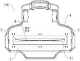
- FIG. 1is a top plan view of a charging stand for a vacuum cleaner in accordance with an embodiment of the present invention
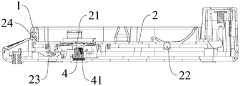
- FIG. 2is a longitudinal cross-sectional view of a charging stand in which a pedal is in a first position, in accordance with an embodiment of the present invention
- FIG. 3is a longitudinal cross-sectional view of a charging stand in which a pedal is in a second position, in accordance with an embodiment of the present invention
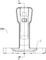
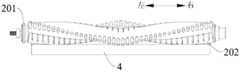
- FIG. 4is a schematic view of a charging portion of a charging stand and a vacuum cleaner according to an embodiment of the present invention
- Figure 5is another schematic view of the charging portion of the charging stand and the vacuum cleaner according to an embodiment of the present invention.
- FIG. 6is a transverse cross-sectional view of a charging stand in which a safety device on the left side is disengaged from a pedal and a safety device on the right side is engaged with a pedal according to an embodiment of the present invention
- FIG. 7is a plan view of a charging stand for a vacuum cleaner in accordance with another embodiment of the present invention.
- Figure 8is a cross-sectional view taken along line A-A of Figure 7;
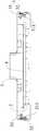
- FIG 9is a front elevational view of the charging stand for the vacuum cleaner shown in Figure 7;
- Figure 10is a cross-sectional view taken along line B-B of Figure 9;
- Figure 11is a schematic view showing the structure of a blade and a roller brush according to an embodiment of the present invention.
- Figure 12is another schematic structural view of the blade and the roller brush shown in Figure 11;
- FIG. 13is a partial schematic view of a charging stand in accordance with an embodiment of the present invention.
- Figure 14is a schematic illustration of a vacuum cleaner, a flap and a blade in accordance with an embodiment of the present invention
- Figure 15is a cross-sectional view taken along line C-C of Figure 14;
- Figure 16is a bottom plan view of the cleaner, the flap and the blade shown in Figure 14;
- Figure 17is a rear elevational view of a charging stand for a vacuum cleaner in accordance with an embodiment of the present invention.
- Figure 18is an exploded view of a charging stand and a charger for a vacuum cleaner according to an embodiment of the present invention
- FIG. 19is a schematic structural view of a charging stand and a charger for a vacuum cleaner according to an embodiment of the present invention, wherein the charger is in a stowed state.
- 3safety protection device; 31: safety protection member; 311: fitting groove; 32: resetting member;
- 200vacuum cleaner
- 201roller brush
- 202roller brush boss.
- first and secondare used for descriptive purposes only and are not to be construed as indicating or implying a relative importance or implicitly indicating the number of technical features indicated. Thus, features defining “first” and “second” may include one or more of the features either explicitly or implicitly. In the description of the present invention, "a plurality” means two or more unless otherwise stated.
- connectionIn the description of the present invention, it should be noted that the terms “installation”, “connected”, and “connected” are to be understood broadly, and may be fixed or detachable, for example, unless otherwise explicitly defined and defined. Connected, or integrally connected; can be mechanical or electrical; can be directly connected, or indirectly connected through an intermediate medium, can be the internal communication of the two components.
- Connected, or integrally connectedcan be mechanical or electrical; can be directly connected, or indirectly connected through an intermediate medium, can be the internal communication of the two components.
- the specific meaning of the above terms in the present inventioncan be understood in a specific case by those skilled in the art.
- the first feature "on” or “under” the second featuremay include direct contact of the first and second features, and may also include first and second features, unless otherwise specifically defined and defined. It is not in direct contact but through additional features between them.
- the first feature "above”, “above” and “above” the second featureincludes the first feature directly above and above the second feature, or merely indicating that the first feature is horizontally higher than The second feature.
- the first feature “below”, “below” and “below” the second featureincludes the first feature directly above and above the second feature, or merely the first feature level being less than the second feature.
- a charging stand 100 for a vacuum cleaner 200will now be described with reference to Figs.
- the charging stand 100can be charged by a vacuum cleaner 200 such as a rechargeable vacuum cleaner.
- a charging stand 100 for a vacuum cleanerincludes a body 1, a charger 7, and a bobbin 6.
- the charger 7is connected to the body 1 via a power line 71, and the charger 7 is provided with a tab 72.
- the charger 7is electrically connected to an external power source (not shown), for example, when the charger 7 is inserted into the socket, the tab 72 extends into the socket, at which point the vacuum cleaner can be charged.
- the bobbin 6is disposed on the body 1, and the bobbin 6 is formed with a slot 611, wherein the tab 72 is adapted to cooperate with the slot 611, and the power cord 71 is adapted to be wound around the bobbin 6.
- the charger 7can be pulled out of the socket, and the tab 72 of the charger 7 can be inserted into the slot 611 on the bobbin 6, so that the charger 7 can be fixed to the bobbin 6 on.
- the power cord 71is wound around the bobbin 6. Thereby, the power line 71 can be made neat, the storage of the charger 7 can be facilitated, and the overall occupied space of the charging stand 100 can be reduced.
- the power supply line 71can be wound around the bobbin 6, and the charger 7 can be fixed to the bobbin 6.
- the power line 71can be made neat, the storage of the charger 7 can be facilitated, and the overall occupied space of the charging stand 100 can be reduced.
- the bobbin 6includes a fixing portion 61 and a winding portion 62 which are connected to each other, wherein the socket 611 is formed on the fixing portion 61, and the power supply line 71 is adapted to be wound around the winding portion 62.
- the winding portion 62for example, the rear end in FIG. 3
- the cross-sectional area of the fixing portion 61is larger than the winding portion. The cross-sectional area of 62.
- the power supply line 71is easily wound around the winding portion 62, and the power supply line 71 is not easily detached from the bobbin 6.
- the direction “front”refers to the direction of the charging stand 100 near the user, and the opposite direction is defined as “rear”.
- the bobbin 6is movably disposed on the body 1 between the storage position and the winding position, and the winding portion 62 is located in the body 1 when the bobbin 6 is in the storage position, when the bobbin 6 is located
- the wire winding portion 62protrudes outside the body 1 at the line position.
- the bobbin 6can be housed in the body 1. After the charging is completed, the bobbin 6 can be pulled back from the inside of the body 1 to facilitate the insertion of the tab 72 on the charger 7. It is inserted into the slot 611 on the holder and facilitates winding the power cord 71 around the winding portion 62.
- a charging stand 100 for a vacuum cleaner 200further includes a step 2 and a safety protection device 3.
- the body 1is provided with a blade 4 which can cut the hair or the like on the roller brush 201 of the vacuum cleaner 200 placed on the charging stand 100.
- the charging stand 100not only has a charging The function of the electric power can also clean the hair and the like wound around the roller brush 201, thereby expanding the function of the charging stand 100, and also facilitating the cleaning of the roller brush 201, simplifying the cleaning process of the roller brush 201.
- the vacuum cleaner 200may be a rechargeable vacuum cleaner or other types of vacuum cleaners 200.
- the pedal 2is disposed on the body 1, and the pedal 2 is pivotable between a first position and a second position, and an opening 21 is formed at a position of the corresponding blade 4 on the pedal 2, and the blade 4 is located when the pedal 2 is in the first position Below the opening 21 (shown in Figure 2), the blade 4 extends out of the opening 21 (shown in Figure 3) when the pedal 2 is in the second position.
- the pedal 2is in the first position, the blade 4 is received in the body 1 and is not exposed from the opening 21.
- the rechargeable vacuum cleanercan be placed on the charging stand 100 for charging, and the safety of the charging stand 100 is ensured. Sex.
- the blade 4projects from the opening 21, at which time the cleaner 200 is activated to rotate the roller 201, so that the blade 4 can effectively cut the hair or the like wound around the roller brush 201.
- the security device 3may be one or plural. When the safety protection device 3 is one, the safety protection device 3 is disposed on the body 1. The safety protection device 3 is often matched with the pedal 2, and when the safety protection device 3 is toggled, the safety protection device 3 is disengaged from the pedal 2 to make the pedal 2 Moving from the first position to the second position.
- each safety protection device 3is disposed on the body 1 at a distance from each other, and each safety protection device 3 is often matched with the pedal 2 when at least two safety protection devices 3 are pushed.
- the two safety devices 3are disengaged from the pedal 2 to move the pedal 2 from the first position to the second position.
- the safety device 3is normally held in cooperation with the pedal 2 to maintain the pedal 2 in the first position, that is, the blade 4 is located in the body 1, which can effectively prevent the pedal 2 from being directly moved to the second position to expose the blade 4 to cause the user
- it is necessary to push all the safety protection devices 3 at the same timeso that all the safety protection devices 3 are disengaged from the pedal 2, and the pedal 2 is released, and thereafter
- the pedal 2can be rotated to the second position to expose the blade 4, thereby cutting the hair on the roller brush 201. In this process, if only a part of the safety protection device 3 is pushed, the pedal 2 still cannot move to the second position, thereby further ensuring the safety of the user's use.
- the charging stand 100 for the cleaner 200expands the function of the charging stand 100 by providing the blade 4 on the body 1, and further, by providing the pivotable pedal 2 and at least two safety protection devices 3 The safety of the charging stand 100 can be effectively ensured.
- the pedal 2is horizontally disposed when the pedal 2 is in the first position, as shown in FIG. 2, thereby making the charging stand 100 an overall appearance, and when the rechargeable vacuum cleaner is charged, the rechargeable vacuum cleaner can Placed horizontally on the pedal 2.
- the front end of the pedal 2is below the first position when the pedal 2 is in the second position, as shown in FIG. That is, simply stepping down the pedal 2 can move the pedal 2 to the second position, thereby greatly facilitating The user.
- the direction "front”refers to the direction of the charging stand 100 near the user, and the opposite direction is defined as "rear".
- the rotation angle of the pedal 2 from the first position to the second positionis ⁇ , wherein ⁇ satisfies: 0° ⁇ ⁇ ⁇ 60°.
- ⁇can be 30°.
- ⁇further satisfies: 1° ⁇ ⁇ ⁇ 10°.
- ⁇can be 3° or 5°. It can be understood that the specific value of ⁇ can be adaptively changed according to actual requirements, and the present invention does not specifically limit this.
- the upper end of the blade 4is preferably lower than the lower surface of the pedal 2, of course, the upper end of the blade 4 may also be higher than the lower surface of the pedal 2 but lower than its upper surface (not shown).
- the opening 21extends in the left-right direction
- the longitudinal direction of the blade 4is the same as the above-described extending direction of the opening 21, and the longitudinal direction of the blade 4 is the same as the longitudinal direction of the roller brush 201, so that the blade 4 can be further The hair on the roller brush 201 is sufficiently cut.
- the blade 4extends straight in the longitudinal direction of the blade 4 as shown in Fig. 7, whereby the processing is simple and the cost is low.
- the blade 4can also be curved in the longitudinal direction thereof, whereby the stability of the blade 4 can be effectively ensured during the process of cutting the hair, so that the cutting effect of the blade 4 is better.
- the blade 4extends in an arc shape in its length direction.
- the blade 4is bent in a direction away from the center of the body 1, in particular, the blade 4 is offset from the central axis of the roller 201. However, it is bent toward the center of the roller brush 201, so that the hair wound around the roller brush 201 can be better cut.
- the blade 4can also extend in a wavy line in its length direction (not shown), whereby the stability of the blade 4 during the cutting process can also be ensured and is not easily deformed.
- the body 1has a base 11 on which the blade 4 is provided, and the blade 4 is adapted to cut the hair wound around the roller brush of the cleaner.
- the upper end of the blade 4is brought into contact with a roller boss 202 (not shown) on the roller brush to cut off the hair wound around the roller boss 202.
- the vacuum cleanermay be a rechargeable vacuum cleaner or other types of vacuum cleaners.
- the elastic member 42is disposed between the blade 4 and the base 11, and optionally, the elastic member 42 is a soft rubber, but is not limited thereto. Therefore, during the operation of the charging stand 100, when the blade 4 and the rotating roller boss 202 are excessively excessively loaded, the height of the blade 4 can be automatically adjusted by the elastic member 42, so that the blade 4 does not overlap with the roller boss. The 202 contact is excessive, thereby greatly reducing the positioning accuracy of the blade 4, reducing the cost, and improving the product qualification rate.
- the charging stand 100further includes a tool holder 41, and the tool holder 41 is disposed on the base 11, wherein the tool holder 41 can be disposed on the inner wall of the base 11 (for example, On the bottom wall of 2).
- the blade 4is provided on the tool holder 41, for example, the blade 4 can be inserted into the tool holder 41.
- the blade 4is preferably arranged vertically so as to be effective Cut the hair wrapped around the roller brush.
- the elastic member 42is disposed between the blade 4 and the blade holder 41 and/or between the blade holder 41 and the base 11. Specifically, the elastic member 42 may be disposed only between the blade 4 and the blade holder 41, or may be disposed only between the blade holder 41 and the base 11, or may be disposed between the blade 4 and the blade holder 41 at the same time. Between 41 and the base 11. For example, referring to Fig. 13, the elastic member 42 is disposed between the holder 41 and the base 11, and the upper end of the elastic member 42 is coupled to the lower end of the holder 41.
- the housing 11is formed with a receiving groove 111 for accommodating the elastic member 42.
- the accommodating groove 111may be formed by a portion of the inner wall of the base 11 recessed in a direction away from the center of the base 11. Thereby, the attachment and detachment of the elastic member 42 is facilitated, and the position of the elastic member 42 can be stabilized, thereby improving the overall performance of the charging stand 100.
- the upper surface of the elastic member 42is higher than the upper surface of the base 11.
- the upper surface of the elastic member 42is higher than the upper surface of the bottom wall of the base 11. Thereby, it is easy to adjust the height of the blade 4.
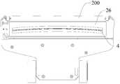
- the pedal 2is provided with a flap 26 on which the opening 21 is formed.
- the flap 26is preferably disposed adjacent the ground brush port of the cleaner 200 and below the ground brush port, at which point the distance between the flap 26 and the ground brush port is relatively short. Therefore, when the hair is cut, the cut hair which is pulled out by the roller brush 2 falls on the flap 26 and does not exceed the dust collecting range of the cleaner 200, so that the cut hair can be prevented from falling on the vacuum cleaner 200. Secondary pollution caused by the scope.
- the flap 26is horizontally disposed. Thereby, the concentrated distribution of the hair falling on the flap 26 can be avoided, thereby facilitating the vacuum cleaner 200 to suck the hair on the flap 26 into the dust cup, improving the dust collecting efficiency. In addition, it can save materials and reduce material costs.
- a relief groove 261is formed on the lower surface of the portion of the flap 26 adjacent to the opening 21.
- the inner wall of the escape groove 261is configured to gradually decrease in a direction toward the center of the opening 21 and the upper surface of the flap 26, that is, the thickness of the portion of the pedal 2 adjacent to the opening 21 in the direction toward the opening 21. Gradually thinning. Thereby, the blade 4 can be prevented from hitting the flap 26, prolonging the service life of the flap 26, thereby reducing the use cost.
- the flap 26may be a soft rubber flap, but is not limited thereto.
- the flap 26may be a rigid plastic flap or the like, as long as it can ensure that the hair drawn by the roller brush 201 falls within the dust collecting range of the vacuum cleaner 200, which is not specifically limited in the present invention.
- At least one reinforcing rib 25is provided on the lower surface of the pedal 2.
- the reinforcing ribs 25may be plural, and the plurality of reinforcing ribs 25 are evenly spaced on the lower surface of the pedal 2.
- the strength of the pedal 2can be effectively ensured.
- the blade 4is adapted to cut the hair on the roller brush 201 of the cleaner 200 placed on the pedal 2 when the blade 4 projects out of the opening 21, with reference to Figure 9 in conjunction with Figure 10, the charging stand 100 described above Enter one
- the stepincludes: a micro switch 5, the micro switch 5 is disposed in the body 1, and when the pedal 2 is in the second position, the micro switch 5 is activated to stop charging the charging stand 100 and rotate the roller 201.
- the pedal 2is pivotally coupled within the body 1 by a pivot shaft 22 disposed at the rear of the charging base 100 and above the pedal 2, when the pedal 2 is depressed
- the rear end of the pedal 2is tilted upward and touches the micro switch 5, so that the micro switch 5 can cut off the charging function of the charging stand 100, stop charging the rechargeable vacuum cleaner placed on the pedal 2, and transmit a signal to the rechargeable vacuum cleaner.
- the roller brush 201rotates, and the blade 4 realizes cutting hair.
- the specific structure and working principle of the micro switch 5are both existing and will not be described in detail herein.
- the pedal 2has a first end and a second end, and the first end of the pedal 2 is pivotally coupled to the body 1 via a pivot shaft 22, the pedal A resilient return member 23 is provided between the second end of the body 2 and the body 1.
- the resilient return member 23is configured to urge the pedal 2 in a direction toward the first position, i.e., the pedal 2 is often held in the first position.
- the resilient return member 23is a spring.
- the pedal 2extends in the front-rear direction
- the first end of the pedal 2is the rear end of the pedal 2
- the second end of the pedal 2is the front end of the pedal 2
- the rear end of the pedal 2
- the pivot shaft 22 extending in the left-right directionis pivotally coupled to the body 1.
- the springis disposed at the front end of the pedal 2 and between the lower surface of the pedal 2 and the bottom wall of the body 1, and the spring always pushes the pedal 2 upward to make the pedal 2 Keep in the horizontal position.
- a side of the body 1 adjacent to the second end of the pedal 2is provided with a limiting member 24, and the limiting member 24 is located on a side of the pedal 2 remote from the elastic returning member 23.
- the limiting member 24is a baffle, and the baffle is disposed on the front side of the body 1 and is opposite to the upper surface of the pedal 2, thereby preventing the pedal 2 from being under the action of the spring. Continue to turn up.
- the rechargeable vacuum cleanerwhen the rechargeable vacuum cleaner needs to be charged, the rechargeable vacuum cleaner can be directly placed on the pedal 2 of the charging stand 100 for charging.
- the vacuum cleaner 200(not limited to the rechargeable vacuum cleaner) is placed on the pedal 2
- the front portion of the cleaner 200can be pressed down, and the front end of the pedal 2 is moved downward, so that the blade 4 can be moved from the pedal.
- the opening 21 of the 2extends, and the vacuum cleaner 200 is activated to rotate the roller 201 (for example, by the micro switch 5 described above) to realize hair cutting, as shown in FIG.
- the top of the body 1is open, the pedal 2 is disposed in the body 1, the upper surface of the pedal 2 is lower than the upper end surface of the body 1, and the pedal 2 and the bottom wall of the body 1 are spaced apart from each other, the pedal A receiving space is defined between the body 2 and the body 1, and a blade 4, a spring or the like can be placed in the receiving space.
- each security protection device 3includes: security protection The safety member 31 is disposed on the side of the pedal 2, and the safety protection member 31 is formed with a fitting groove 311 adapted to cooperate with the edge of the pedal 2.
- the reset member 32is disposed on the safety protection member 31 and the body 1. Between the reset members 32 is configured to constantly urge the safety protector 31 toward the center of the pedal 2.
- the reset member 32is a spring or a spring.
- the engagement groove 311 on the safety protection member 31can be engaged with the edge of the pedal 2 to prevent the pedal 2 from moving to the second position to expose the blade 4, and by providing the reset member 32, When no external force acts on the safety protection member 31, the safety protection member 31 can engage the engagement groove 311 with the edge of the pedal 2 under the action of the reset member 32 to realize a safety protection function.
- the safety guard 31is pivotally coupled to the body 1, and the safety guard 31 has a first end (eg, the upper end in FIG. 6) and a second end (eg, the lower end in FIG. 6).
- the engaging groove 311is formed at the second end of the safety protector 31, and when the first end of the safety protector 31 is toggled, the second end of the safety protector 31 is moved away from the center of the pedal 2 to make the edge of the pedal 2 Disengaged from the engagement groove 311.
- the safety protection member 31is vertically disposed, the engagement groove 311 is open toward the side of the center of the pedal 2 and is engaged with the edge of the pedal 2, and if the pedal 2 is depressed, the edge of the pedal 2 and the engagement groove The inner wall of the 311 is abutted so that the pedal 2 cannot be moved to the second position, i.e., the blade 4 cannot protrude from the opening 21, improving safety.
- the first end of the safety protection member 31can be pushed downward, and the engagement groove 311 of the second end of the safety protection member 31 is moved away from the pedal 2 and separated from the pedal 2, With the lower pedal 2, the pedal 2 can be moved to the second position, causing the blade 4 to extend out of the opening 21 to effect hair cutting.
- the first end of the safety guard 31protrudes from the inner side of the body 1 and is located above the pedal 2. Thereby, it is convenient to dial the first end of the safety protector 31.
- the first end of the safety protection member 31has a guiding surface adapted to toggle the first end of the safety protection member 31.
- the guide surfaceis configured to extend obliquely from top to bottom toward the center of the pedal 2.
- the guide surfaceis formed as an inclined plane or a beveled surface that extends obliquely from the top to the bottom toward the center of the pedal 2.
- FIG. 7there are two safety protection devices 3, and two safety protection devices 3 are respectively located on the left and right sides of the body 1.
- two safety protection devices 3it is necessary to simultaneously push the two safety protection devices 3 and step on the pedal 2, and the blade 4 can protrude from the inside of the charging stand 100.
- the security device 3will be described as an example.
- the safety protection members 31 of the two safety protection devices 3cooperate with the edge of the pedal 2 under the action of the resetting member 32, and even if the pedal 2 is depressed, the pedal 2 cannot move to the second position. That is, the blade 4 cannot protrude from the opening 21.
- the full protection device 3remains in engagement with the edge of the pedal 2, at which time the pedal 2 is also unable to move to the second position, ensuring the safety of the charging stand 100.
- the rechargeable vacuum cleanerneeds to be charged or the vacuum cleaner 200 is cut, the vacuum cleaner 200 can be placed in the charging stand 100.
- the vacuum cleaner 200can dial the safety protection members 31 of the two safety protection devices 3 to make Disengaged from the pedal 2, the rechargeable vacuum cleaner can be charged at this time. If the pedal 2 is depressed and moved to the second position, the blade 4 extends out of the opening 21 on the pedal 2, at which time the hair can be cut.
- the function of the charging stand 100is expanded, and the use safety of the charging stand 100 is improved.
Landscapes
- Engineering & Computer Science (AREA)
- Mechanical Engineering (AREA)
- Robotics (AREA)
- Power Engineering (AREA)
- Nozzles For Electric Vacuum Cleaners (AREA)
Abstract
Description
Translated fromChinese本发明涉及吸尘器技术领域,尤其是涉及一种用于吸尘器的充电座。The present invention relates to the field of vacuum cleaners, and more particularly to a charging stand for a vacuum cleaner.
相关技术中,部分充电式吸尘器带有充电座,充电器插入插座时,可以对吸尘器进行充电。充电完成后,充电器需从插座上拔下,此时充电器只能随处放置。然而,充电器随处放置时,电源线紊乱,不方便收纳。In the related art, a part of the rechargeable vacuum cleaner has a charging stand, and the vacuum cleaner can be charged when the charger is inserted into the socket. After charging is complete, the charger needs to be unplugged from the outlet, and the charger can only be placed anywhere. However, when the charger is placed anywhere, the power cord is disordered and inconvenient to store.
发明内容Summary of the invention
本发明旨在至少解决现有技术中存在的技术问题之一。为此,本发明的一个目的在于提出一种用于吸尘器的充电座,所述充电座的充电器便于收纳。The present invention aims to solve at least one of the technical problems existing in the prior art. To this end, it is an object of the present invention to provide a charging stand for a vacuum cleaner, the charger of which is convenient for storage.
根据本发明的用于吸尘器的充电座,包括:本体;充电器,所述充电器通过电源线与所述本体相连,所述充电器上设有插片;以及绕线架,所述绕线架设在所述本体上,所述绕线架上形成有插槽,其中所述插片适于与所述插槽配合,所述电源线适于缠绕在所述绕线架上。A charging stand for a vacuum cleaner according to the present invention includes: a body; a charger connected to the body via a power cord, the charger being provided with a tab; and a bobbin, the winding Mounted on the body, the bobbin is formed with a slot, wherein the tab is adapted to cooperate with the slot, and the power cord is adapted to be wound on the bobbin.
根据本发明的用于吸尘器的充电座,通过在充电座上设置绕线架,可将电源线缠绕在绕线架上,并将充电器固定在绕线架上。由此,可使得电源线整齐,便于充电器的收纳,且减小了充电座的整体占用空间。According to the charging stand for a vacuum cleaner of the present invention, by providing a bobbin on the charging stand, the power cord can be wound around the bobbin and the charger can be fixed to the bobbin. Thereby, the power line can be neat, the storage of the charger can be facilitated, and the overall occupied space of the charging stand can be reduced.
根据本发明的其中一个示例,所述绕线架包括彼此相连的固定部和绕线部,其中所述插槽形成在所述固定部上,所述电源线适于缠绕在所述绕线部上。According to an example of the present invention, the bobbin includes a fixing portion and a winding portion which are connected to each other, wherein the socket is formed on the fixing portion, and the power cord is adapted to be wound around the winding portion on.
根据本发明的其中一个示例,所述绕线架在收纳位置和绕线位置之间可移动地设在所述本体上,当所述绕线架位于所述收纳位置时所述绕线部位于所述本体内,当所述绕线架位于所述绕线位置时所述绕线部伸出所述本体外。According to an example of the present invention, the bobbin is movably disposed on the body between a stowed position and a winding position, and the bobbin is located when the bobbin is in the stowed position In the body, the winding portion protrudes outside the body when the bobbin is located at the winding position.
根据本发明的其中一个示例,所述用于吸尘器的充电座进一步包括:踏板,所述踏板设在所述本体上,且所述踏板在第一位置和第二位置之间可枢转。According to an example of the present invention, the charging stand for the vacuum cleaner further includes: a pedal provided on the body, and the pedal is pivotable between the first position and the second position.
根据本发明的其中一个示例,所述用于吸尘器的充电座进一步包括:安全保护装置,所述安全保护装置设在所述本体上,所述安全保护装置与所述踏板常配合,当拨动所述安全保护装置时所述安全保护装置与所述踏板脱离配合以使所述踏板从所述第一位置运动至所述第二位置。According to an example of the present invention, the charging stand for the vacuum cleaner further includes: a safety protection device, the safety protection device is disposed on the body, and the safety protection device is often matched with the pedal when being toggled The safety device disengages from the pedal to move the pedal from the first position to the second position.
根据本发明的其中一个示例,所述安全保护装置包括至少两个,所述至少两个安全保护装置彼此间隔开地设在所述本体上,当拨动所述至少两个安全保护装置时所述至少两个安全保护装置与所述踏板脱离配合以使所述踏板从所述第一位置运动至所述第二位置。According to one of the examples of the present invention, the safety protection device includes at least two, the at least two safety protection devices are disposed on the body spaced apart from each other when the at least two safety protection devices are toggled The at least two safety devices are disengaged from the pedal to move the pedal from the first position to the second position.
根据本发明的其中一个示例,所述安全保护装置包括:安全保护件,所述安全保护件设在所述踏板的侧面,所述安全保护件上形成有适于与所述踏板的边缘配合的配合槽;和复位件,所述复位件设在所述安全保护件和所述本体之间,所述复位件被构造成朝向所述踏板中心的方向常推动所述安全保护件。According to an example of the present invention, the safety protection device includes: a safety protection member disposed on a side of the pedal, and the safety protection member is formed with a fitting to fit the edge of the pedal And a reset member disposed between the safety protector and the body, the reset member being configured to constantly urge the safety protector toward a center of the pedal.
根据本发明的其中一个示例,所述安全保护件可枢转地连接在所述本体上,所述安全保护件具有第一端和第二端,其中所述配合槽形成在所述安全保护件的所述第二端,当拨动所述安全保护件的所述第一端时所述安全保护件的所述第二端朝向远离所述踏板中心的方向运动以使所述踏板的边缘与所述配合槽脱离配合。According to one of the examples of the present invention, the safety protector is pivotally coupled to the body, the safety guard having a first end and a second end, wherein the mating slot is formed in the safety guard The second end of the safety guard moves the second end of the safety guard away from the center of the pedal when the first end of the safety guard is toggled to cause the edge of the pedal to The mating groove is disengaged.
根据本发明的其中一个示例,所述安全保护件的所述第一端具有适于拨动所述安全保护件的所述第一端的导向面。According to one of the examples of the present invention, the first end of the safety protector has a guide surface adapted to toggle the first end of the safety guard.
根据本发明的其中一个示例,所述导向面被构造成从上到下朝向所述踏板的中心倾斜延伸。According to an example of the present invention, the guide surface is configured to extend obliquely from top to bottom toward the center of the pedal.
根据本发明的其中一个示例,所述导向面形成为从上到下朝向所述踏板的中心倾斜延伸的斜平面或斜曲面。According to an example of the present invention, the guide surface is formed as an inclined plane or a beveled surface that extends obliquely from top to bottom toward the center of the pedal.
根据本发明的其中一个示例,当所述踏板位于所述第一位置时,所述安全保护件的所述第一端伸出所述本体的内侧面。According to one of the examples of the present invention, the first end of the safety guard protrudes from an inner side of the body when the pedal is in the first position.
根据本发明的其中一个示例,所述复位件为弹片或弹簧。According to one of the examples of the invention, the reset member is a spring or a spring.
根据本发明的其中一个示例,所述安全保护装置为两个且所述两个安全保护装置分别位于所述本体的左侧和右侧。According to one of the examples of the invention, the security devices are two and the two security devices are located on the left and right sides of the body, respectively.
根据本发明的其中一个示例,当所述踏板位于所述第一位置时所述踏板水平设置。According to one of the examples of the present invention, the pedal is horizontally set when the pedal is in the first position.
根据本发明的其中一个示例,所述踏板从所述第一位置旋转至所述第二位置的旋转角度为α,其中所述α满足:0°<α≤60°。According to one of the examples of the present invention, the rotation angle of the pedal from the first position to the second position is α, wherein the α satisfies: 0° < α ≤ 60°.
根据本发明的其中一个示例,所述α进一步满足:1°≤α≤10°。According to one of the examples of the present invention, the α further satisfies: 1° ≤ α ≤ 10°.
根据本发明的其中一个示例,所述本体的顶部敞开,所述踏板设在所述本体内且与所述本体的底壁彼此间隔开。According to one of the examples of the invention, the top of the body is open, the pedals being disposed within the body and spaced apart from the bottom wall of the body.
根据本发明的其中一个示例,所述踏板的下表面上设有至少一个加强筋。According to an example of the invention, at least one reinforcing rib is provided on the lower surface of the pedal.
根据本发明的其中一个示例,所述本体内设有刀片,所述踏板上对应所述刀片的位置处形成有开口,当所述踏板位于所述第二位置时所述刀片伸出所述开口以适于切断放置在所述踏板上的吸尘器内的滚刷上的毛发,当所述踏板位于所述第一位置时所述刀片位于所述开口的下方。According to one of the examples of the present invention, the body is provided with a blade, and the pedal corresponds to the position of the bladeThe opening is formed with an opening that protrudes from the opening when the pedal is in the second position to be adapted to cut hair on a roller brush placed in a vacuum cleaner on the pedal, when the pedal is located The blade is located below the opening in the first position.
根据本发明的其中一个示例,所述用于吸尘器的充电座进一步包括:微动开关,所述微动开关设在所述本体内,当所述踏板位于所述第二位置时触动所述微动开关以使所述充电座停止充电并使所述滚刷旋转。According to an example of the present invention, the charging stand for the vacuum cleaner further includes: a micro switch disposed in the body, the micro pedal being touched when the pedal is in the second position The switch is activated to stop charging the charging stand and rotate the roller brush.
根据本发明的其中一个示例,所述刀片竖直设置。According to one of the examples of the invention, the blades are arranged vertically.
根据本发明的其中一个示例,所述刀片在所述刀片的长度方向上曲线延伸。According to one of the examples of the invention, the blade extends in a curve in the length direction of the blade.
根据本发明的其中一个示例,所述刀片在所述长度方向上弧形或波浪形延伸。According to one of the examples of the invention, the blade extends in an arc or wave shape in the length direction.
根据本发明的其中一个示例,所述本体具有底座,所述刀片和所述底座之间设有弹性件。According to one of the examples of the present invention, the body has a base, and an elastic member is disposed between the blade and the base.
根据本发明的其中一个示例,所述用于吸尘器的充电座进一步包括:刀架,所述刀架设在所述底座上,其中所述刀片设在所述刀架上,所述弹性件设在所述刀片和所述刀架之间和/或所述刀架和所述底座之间。According to an example of the present invention, the charging stand for a vacuum cleaner further includes: a tool holder, the tool holder is disposed on the base, wherein the blade is disposed on the tool holder, and the elastic member is disposed on Between the blade and the tool holder and/or between the tool holder and the base.
根据本发明的其中一个示例,当所述弹性件设在所述刀架和所述底座之间时,所述底座上形成有用于容纳所述弹性件的容纳槽。According to an example of the present invention, when the elastic member is disposed between the holder and the base, a receiving groove for accommodating the elastic member is formed on the base.
根据本发明的其中一个示例,所述弹性件的上表面高于所述底座的上表面。According to an example of the invention, the upper surface of the elastic member is higher than the upper surface of the base.
根据本发明的其中一个示例,所述弹性件为软胶。According to one of the examples of the invention, the elastic member is a soft glue.
根据本发明的其中一个示例,所述踏板上设有挡片,所述挡片上形成有所述开口。According to an example of the present invention, the pedal is provided with a flap on which the opening is formed.
根据本发明的其中一个示例,所述挡片水平设置。According to one of the examples of the present invention, the flap is horizontally disposed.
根据本发明的其中一个示例,所述挡片的邻近所述开口的部分的下表面上形成有避让槽。According to an example of the present invention, a relief groove is formed on a lower surface of a portion of the flap adjacent to the opening.
根据本发明的其中一个示例,所述避让槽的内壁被构造成朝向所述开口中心的方向、与所述挡片的上表面之间的距离逐渐减小。According to an example of the present invention, an inner wall of the escape groove is configured to gradually decrease in a direction toward a center of the opening and a distance from an upper surface of the flap.
根据本发明的其中一个示例,所述挡片为软胶挡片。According to one of the examples of the present invention, the flap is a soft flap.
根据本发明的其中一个示例,所述踏板具有第一端和第二端,所述踏板的所述第一端通过枢转轴可枢转地连接在所述本体上,所述踏板的所述第二端和所述本体之间设有弹性复位件,所述弹性复位件被构造成朝向所述第一位置的方向常推动所述踏板。According to one of the examples of the present invention, the pedal has a first end and a second end, the first end of the pedal being pivotally coupled to the body by a pivot shaft, the first of the pedal An elastic return member is disposed between the two ends and the body, and the elastic return member is configured to constantly push the pedal toward the first position.
根据本发明的其中一个示例,所述本体的邻近所述踏板的第二端的一侧设有限位件,所述限位件位于所述踏板的远离所述弹性复位件的一侧。According to one of the examples of the present invention, a side of the body adjacent to the second end of the pedal is provided with a limiting member, the limiting member being located on a side of the pedal remote from the elastic returning member.
根据本发明的其中一个示例,所述弹性复位件为弹簧。According to one of the examples of the invention, the elastic return member is a spring.
根据本发明的其中一个示例,所述踏板沿前后方向延伸,所述踏板的所述第一端为所述踏板的后端,所述踏板的所述第二端为所述踏板的前端。According to an example of the present invention, the pedal extends in a front-rear direction, the first end of the pedal is a rear end of the pedal, and the second end of the pedal is a front end of the pedal.
本发明的附加方面和优点将在下面的描述中部分给出,部分将从下面的描述中变得明显,或通过本发明的实践了解到。The additional aspects and advantages of the invention will be set forth in part in the description which follows.
本发明的上述和/或附加的方面和优点从结合下面附图对实施例的描述中将变得明显和容易理解,其中:The above and/or additional aspects and advantages of the present invention will become apparent and readily understood from
图1是根据本发明实施例的用于吸尘器的充电座的俯视图;1 is a top plan view of a charging stand for a vacuum cleaner in accordance with an embodiment of the present invention;
图2是根据本发明实施例的充电座的纵向剖面图,其中踏板位于第一位置;2 is a longitudinal cross-sectional view of a charging stand in which a pedal is in a first position, in accordance with an embodiment of the present invention;
图3是根据本发明实施例的充电座的纵向剖面图,其中踏板位于第二位置;3 is a longitudinal cross-sectional view of a charging stand in which a pedal is in a second position, in accordance with an embodiment of the present invention;
图4是根据本发明实施例的充电座和吸尘器的滚刷部分的示意图;4 is a schematic view of a charging portion of a charging stand and a vacuum cleaner according to an embodiment of the present invention;
图5是根据本发明实施例的充电座和吸尘器的滚刷部分的另一个示意图;Figure 5 is another schematic view of the charging portion of the charging stand and the vacuum cleaner according to an embodiment of the present invention;
图6是根据本发明实施例的充电座的横向剖面图,其中左侧的安全保护装置与踏板脱离配合,右侧的安全保护装置与踏板配合;6 is a transverse cross-sectional view of a charging stand in which a safety device on the left side is disengaged from a pedal and a safety device on the right side is engaged with a pedal according to an embodiment of the present invention;
图7是根据本发明另一个实施例的用于吸尘器的充电座的俯视图;Figure 7 is a plan view of a charging stand for a vacuum cleaner in accordance with another embodiment of the present invention;
图8是沿图7中A-A线的剖面图;Figure 8 is a cross-sectional view taken along line A-A of Figure 7;
图9是图7中所示的用于吸尘器的充电座的主视图;Figure 9 is a front elevational view of the charging stand for the vacuum cleaner shown in Figure 7;
图10是沿图9中B-B线的剖面图;Figure 10 is a cross-sectional view taken along line B-B of Figure 9;
图11是根据本发明实施例的刀片和滚刷的结构示意图;Figure 11 is a schematic view showing the structure of a blade and a roller brush according to an embodiment of the present invention;
图12是图11中所示的刀片和滚刷的另一个结构示意图;Figure 12 is another schematic structural view of the blade and the roller brush shown in Figure 11;
图13是根据本发明实施例的充电座的局部示意图;Figure 13 is a partial schematic view of a charging stand in accordance with an embodiment of the present invention;
图14是根据本发明实施例的吸尘器、挡片和刀片的示意图;Figure 14 is a schematic illustration of a vacuum cleaner, a flap and a blade in accordance with an embodiment of the present invention;
图15是沿图14中C-C线的剖面图;Figure 15 is a cross-sectional view taken along line C-C of Figure 14;
图16是图14中所示的吸尘器、挡片和刀片的仰视图;Figure 16 is a bottom plan view of the cleaner, the flap and the blade shown in Figure 14;
图17是根据本发明实施例的用于吸尘器的充电座的后视图;Figure 17 is a rear elevational view of a charging stand for a vacuum cleaner in accordance with an embodiment of the present invention;
图18是根据本发明实施例的用于吸尘器的充电座和充电器的爆炸图;Figure 18 is an exploded view of a charging stand and a charger for a vacuum cleaner according to an embodiment of the present invention;
图19是根据本发明实施例的用于吸尘器的充电座和充电器的结构示意图,其中充电器处于收纳状态。19 is a schematic structural view of a charging stand and a charger for a vacuum cleaner according to an embodiment of the present invention, wherein the charger is in a stowed state.
附图标记:Reference mark:
100:充电座;100: charging stand;
1:本体;11:底座;111:容纳槽;2:踏板;21:开口;22:枢转轴;1: body; 11: base; 111: receiving slot; 2: pedal; 21: opening; 22: pivoting axis;
23:弹性复位件;24:限位件;25:加强筋;26:挡片;261:避让槽;23: elastic reset member; 24: limit member; 25: reinforcing rib; 26: blank; 261: escape groove;
3:安全保护装置;31:安全保护件;311:配合槽;32:复位件;3: safety protection device; 31: safety protection member; 311: fitting groove; 32: resetting member;
4:刀片;41:刀架;42:弹性件;5:微动开关;4: blade; 41: tool holder; 42: elastic member; 5: micro switch;
6:绕线架;61:固定部;611:插槽;62:绕线部;6: bobbin; 61: fixing portion; 611: slot; 62: winding portion;
7:充电器;71:电源线;72:插片;7: charger; 71: power cord; 72: insert;
200:吸尘器;201:滚刷;202:滚刷凸台。200: vacuum cleaner; 201: roller brush; 202: roller brush boss.
下面详细描述本发明的实施例,所述实施例的示例在附图中示出,其中自始至终相同或类似的标号表示相同或类似的元件或具有相同或类似功能的元件。下面通过参考附图描述的实施例是示例性的,仅用于解释本发明,而不能理解为对本发明的限制。The embodiments of the present invention are described in detail below, and the examples of the embodiments are illustrated in the drawings, wherein the same or similar reference numerals are used to refer to the same or similar elements or elements having the same or similar functions. The embodiments described below with reference to the accompanying drawings are intended to be illustrative of the invention and are not to be construed as limiting.
在本发明的描述中,需要理解的是,术语“中心”、“纵向”、“横向”、“长度”、“宽度”、“厚度”、“上”、“下”、“前”、“后”、“左”、“右”、“竖直”、“水平”、“顶”、“底”、“内”、“外”、“顺时针”、“逆时针”、“轴向”、“径向”、“周向”等指示的方位或位置关系为基于附图所示的方位或位置关系,仅是为了便于描述本发明和简化描述,而不是指示或暗示所指的装置或元件必须具有特定的方位、以特定的方位构造和操作,因此不能理解为对本发明的限制。In the description of the present invention, it is to be understood that the terms "center", "longitudinal", "transverse", "length", "width", "thickness", "upper", "lower", "front", " Rear, Left, Right, Vertical, Horizontal, Top, Bottom, Inner, Out, Clockwise, Counterclockwise, Axial The orientation or positional relationship of the "radial", "circumferential" and the like is based on the orientation or positional relationship shown in the drawings, and is merely for the convenience of describing the present invention and simplifying the description, and does not indicate or imply the indicated device or The elements must have a particular orientation, are constructed and operated in a particular orientation and are therefore not to be construed as limiting.
此外,术语“第一”、“第二”仅用于描述目的,而不能理解为指示或暗示相对重要性或者隐含指明所指示的技术特征的数量。由此,限定有“第一”、“第二”的特征可以明示或者隐含地包括一个或者更多个该特征。在本发明的描述中,除非另有说明,“多个”的含义是两个或两个以上。Moreover, the terms "first" and "second" are used for descriptive purposes only and are not to be construed as indicating or implying a relative importance or implicitly indicating the number of technical features indicated. Thus, features defining "first" and "second" may include one or more of the features either explicitly or implicitly. In the description of the present invention, "a plurality" means two or more unless otherwise stated.
在本发明的描述中,需要说明的是,除非另有明确的规定和限定,术语“安装”、“相连”、“连接”应做广义理解,例如,可以是固定连接,也可以是可拆卸连接,或一体地连接;可以是机械连接,也可以是电连接;可以是直接相连,也可以通过中间媒介间接相连,可以是两个元件内部的连通。对于本领域的普通技术人员而言,可以具体情况理解上述术语在本发明中的具体含义。In the description of the present invention, it should be noted that the terms "installation", "connected", and "connected" are to be understood broadly, and may be fixed or detachable, for example, unless otherwise explicitly defined and defined. Connected, or integrally connected; can be mechanical or electrical; can be directly connected, or indirectly connected through an intermediate medium, can be the internal communication of the two components. The specific meaning of the above terms in the present invention can be understood in a specific case by those skilled in the art.
在本发明中,除非另有明确的规定和限定,第一特征在第二特征之“上”或之“下”可以包括第一和第二特征直接接触,也可以包括第一和第二特征不是直接接触而是通过它们之间的另外的特征接触。而且,第一特征在第二特征“之上”、“上方”和“上面”包括第一特征在第二特征正上方和斜上方,或仅仅表示第一特征水平高度高于第二特征。第一特征在第二特征“之下”、“下方”和“下面”包括第一特征在第二特征正上方和斜上方,或仅仅表示第一特征水平高度小于第二特征。In the present invention, the first feature "on" or "under" the second feature may include direct contact of the first and second features, and may also include first and second features, unless otherwise specifically defined and defined. It is not in direct contact but through additional features between them. Moreover, the first feature "above", "above" and "above" the second feature includes the first feature directly above and above the second feature, or merely indicating that the first feature is horizontally higher thanThe second feature. The first feature "below", "below" and "below" the second feature includes the first feature directly above and above the second feature, or merely the first feature level being less than the second feature.
下面参考图1-图19描述根据本发明实施例的用于吸尘器200的充电座100。充电座100可以为吸尘器200例如充电式吸尘器充电。A charging
如图17-图19所示,根据本发明实施例的用于吸尘器的充电座100,包括本体1、充电器7和绕线架6。As shown in FIGS. 17 to 19, a charging
充电器7通过电源线71与本体1相连,充电器7上设有插片72。当充电器7与外部电源(图未示出)电连接时,例如,将充电器7插到插座上时,插片72伸入插座内,此时可以对吸尘器进行充电。The
绕线架6设在本体1上,绕线架6上形成有插槽611,其中插片72适于与插槽611配合,电源线71适于缠绕在绕线架6上。例如,充电结束后,可将充电器7从插座上拔出,并将充电器7的插片72插到绕线架6上的插槽611上,从而充电器7可以固定在绕线架6上。电源线71缠绕在绕线架6上。由此,可使得电源线71整齐,便于充电器7的收纳,且减小了充电座100的整体占用空间。The
根据本发明的用于吸尘器的充电座100,通过在充电座100上设置绕线架6,可将电源线71缠绕在绕线架6上,并将充电器7固定在绕线架6上。由此,可使得电源线71整齐,便于充电器7的收纳,且减小了充电座100的整体占用空间。According to the charging
根据本发明的一些实施例,绕线架6包括彼此相连的固定部61和绕线部62,其中插槽611形成在固定部61上,电源线71适于缠绕在绕线部62上。例如,参照图3,绕线部62的一端(例如,图3中的后端)与固定部61的一端(例如,图3中的前端)相连,固定部61的横截面积大于绕线部62的横截面积。由此,便于将电源线71缠绕在绕线部62上,且电源线71不易从绕线架6上松脱。这里,需要说明的是,方向“前”指的是充电座100的靠近用户的方向,其相反方向被定义为“后”。According to some embodiments of the present invention, the
进一步地,绕线架6在收纳位置和绕线位置之间可移动地设在本体1上,当绕线架6位于收纳位置时绕线部62位于本体1内,当绕线架6位于绕线位置时绕线部62伸出本体1外。例如,在对吸尘器进行充电时,可将绕线架6收纳在本体1内,充电结束后,可将绕线架6从本体1内向后拉出,从而便于将充电器7上的插片72插到固定架上的插槽611上,且便于将电源线71缠绕在绕线部62上。Further, the
如图1-图16所示,根据本发明实施例的用于吸尘器200的充电座100,进一步包括踏板2和安全保护装置3。具体而言,本体1内设有刀片4,刀片4可以对放置在充电座100上的吸尘器200的滚刷201上的毛发等进行切断。此时充电座100不仅具有充电的功能,而且还能对缠绕在滚刷201上的毛发等进行清理,从而扩展了充电座100的功能,同时也方便了对滚刷201的清理,简化了滚刷201的清理过程。这里,需要说明的是,当应用充电座100的清理功能时,吸尘器200可以为充电式吸尘器,也可以为其它类型的吸尘器200。As shown in FIGS. 1 to 16, a charging
踏板2设在本体1上,且踏板2在第一位置和第二位置之间可枢转,踏板2上对应刀片4的位置处形成有开口21,当踏板2位于第一位置时刀片4位于开口21的下方(如图2所示),当踏板2位于第二位置时刀片4伸出开口21(如图3所示)。当踏板2位于上述第一位置时,刀片4收纳在本体1内,而未从开口21处露出,此时充电式吸尘器可以放置在充电座100上实现充电,且保证了充电座100使用的安全性。当踏板2位于上述第二位置时,刀片4从开口21处伸出,此时启动吸尘器200,使滚刷201旋转,从而刀片4可以有效切断缠绕在滚刷201上的毛发等。The
安全保护装置3可以为一个,也可以为多个。当安全保护装置3为一个时,安全保护装置3设在本体1上,安全保护装置3与踏板2常配合,当拨动安全保护装置3时安全保护装置3与踏板2脱离配合以使踏板2从第一位置运动至第二位置。The
当安全保护装置3为多个时,至少两个安全保护装置3彼此间隔开地设在本体1上,每个安全保护装置3与踏板2常配合,当推动至少两个安全保护装置3时至少两个安全保护装置3与踏板2脱离配合以使踏板2从第一位置运动至第二位置。安全保护装置3在通常情况下与踏板2保持配合以使踏板2保持在第一位置,即刀片4位于本体1内,可以有效防止直接使踏板2运动至第二位置使刀片4露出而造成用户受伤的安全隐患;而且,当需要切断滚刷201上的毛发时,需要同时推动所有的安全保护装置3,使所有的安全保护装置3均与踏板2脱离配合,此时踏板2被释放,此后可以使踏板2旋转至第二位置以露出刀片4,从而切断滚刷201上的毛发。在此过程中,如果仅推动部分安全保护装置3,则踏板2仍然不能运动至第二位置,从而进一步保证了用户使用的安全性。When there are a plurality of
根据本发明实施例的用于吸尘器200的充电座100,通过在本体1上设置刀片4,扩展了充电座100的功能,而且,通过设置可枢转的踏板2和至少两个安全保护装置3,可以有效保证充电座100使用的安全性。The charging
根据本发明的一个实施例,当踏板2位于第一位置时踏板2水平设置,如图2所示,由此,使得充电座100整体外形美观,且当充电式吸尘器充电时,充电式吸尘器可以水平地放置在踏板2上。当踏板2位于第二位置时踏板2的前端相对于其第一位置在下方,如图3所示。即只需向下踏下踏板2就可以使踏板2运动至第二位置,从而极大了方便了用户。这里,需要说明的是,方向“前”指的是充电座100的靠近用户的方向,其相反方向被定义为“后”。According to an embodiment of the present invention, the
其中,踏板2从第一位置旋转至第二位置的旋转角度为α,其中α满足:0°<α≤60°。例如,α可以为30°。进一步地,α进一步满足:1°≤α≤10°。例如,α可以为3°或5°。可以理解的是,α的具体数值可以根据实际要求而适应性改变,本发明对此不作特殊限定。Wherein, the rotation angle of the
当踏板2位于第一位置时,刀片4的上端优选低于踏板2下表面,当然,刀片4的上端还可以高于踏板2的下表面但低于其上表面(图未示出)。When the
如图1和图7所示,开口21沿左右方向延伸,刀片4的长度方向与开口21的上述延伸方向相同,且刀片4的长度方向与滚刷201的长度方向相同,从而刀片4可以更充分地切断滚刷201上的毛发。As shown in FIGS. 1 and 7, the
可选地,刀片4在刀片4的长度方向上直线延伸,如图7所示,由此,加工简单且成本低。当然,刀片4还可以在其长度方向上曲线延伸,由此,在切毛发的过程中,可以有效保证刀片4的稳定性,使刀片4的切毛发效果更好。例如,刀片4在其长度方向上弧形延伸,例如,参照图1并结合图11-图13,刀片4朝向远离本体1中心的方向弯曲,具体而言,刀片4偏离滚刷201的中心轴线但朝向邻近滚刷201中心的方向弯曲,从而可以更好地切断缠绕在滚刷201上的毛发。当然,刀片4还可以在其长度方向上波浪线延伸(图未示出),由此,同样可以保证在切毛过程中刀片4的稳定性,且不易变形。Alternatively, the
如图13所示,本体1具有底座11,刀片4设在底座11上,刀片4适于切断缠绕在吸尘器的滚刷上的毛发。在切毛发的过程中,刀片4的上端与滚刷上的滚刷凸台202(图未示出)接触,以便于切断缠绕在设置在滚刷凸台202上的毛发。此时吸尘器可以为充电式吸尘器,也可以为其它类型的吸尘器。As shown in Fig. 13, the
参照图13,弹性件42设在刀片4和底座11之间,可选地,弹性件42为软胶,但不限于此。由此,在充电座100工作过程中,当刀片4与旋转中的滚刷凸台202过盈过多时,可通过弹性件42自动调节刀片4的高度,使刀片4不会与滚刷凸台202接触过多,从而极大地降低了刀片4的定位精度,降低了成本,且提高了产品合格率。Referring to Fig. 13, the
根据本实用新型的一些实施例,如图13所示,充电座100进一步包括:刀架41,刀架41设在底座11上,其中,刀架41可以设在底座11的内壁(例如,图2中的底壁)上。刀片4设在刀架41上,例如,刀片4可以插设在刀架41上。由此,通过设置刀架41,刀片4可以方便且牢靠地安装在底座11上。刀片4优选竖直设置,从而可以有效切断缠绕在滚刷上的毛发。According to some embodiments of the present invention, as shown in FIG. 13, the charging
弹性件42设在刀片4和刀架41之间和/或刀架41和底座11之间。具体而言,弹性件42可以只设在刀片4和刀架41之间,也可以只设在刀架41和底座11之间,还可以同时设在刀片4和刀架41之间、刀架41和底座11之间。例如,参照图13,弹性件42设在刀架41和底座11之间,弹性件42的上端与刀架41的下端相连。The
具体地,当弹性件42设在刀架41和底座11之间时,底座11上形成有用于容纳弹性件42的容纳槽111。参照图13,容纳槽111可以由底座11的内壁的一部分朝向远离底座11中心的方向凹入形成。由此,便于弹性件42的安装和拆卸,且可使得弹性件42的位置稳定,从而提高了充电座100的整体性能。Specifically, when the
可选地,弹性件42的上表面高于底座11的上表面。参照图13,弹性件42的上表面高于底座11的底壁的上表面。由此,便于调节刀片4的高度。Alternatively, the upper surface of the
踏板2上设有挡片26,挡片26上有形成有上述开口21。例如,参照图14-图16,挡片26优选邻近吸尘器200的地刷口设置且位于地刷口的下方,此时挡片26与地刷口之间的距离较近。由此,切毛发时,被滚刷2甩出的切断的毛发会落到挡片26上,不会超出吸尘器200的吸尘范围,从而可以避免上述切断的毛发落在吸尘器200吸不到的范围造成的二次污染。The
可选地,挡片26水平设置。由此,可避免落到挡片26上的毛发集中分布,从而便于吸尘器200将挡片26上的毛发吸进尘杯中,提高了吸尘效率。此外,还可以节省用料,降低材料成本。Optionally, the
如图15所示,挡片26的邻近开口21的部分的下表面上形成有避让槽261。进一步地,避让槽261的内壁被构造成朝向开口21中心的方向、与挡片26的上表面之间的距离逐渐减小,即踏板2的邻近开口21的部分在朝向开口21的方向上厚度逐渐减薄。由此,可防止刀片4碰到挡片26,延长了挡片26的使用寿命,从而降低了使用成本。可选地,挡片26可以为软胶挡片,但不限于此。例如,挡片26也可以为硬质塑料挡片等,只要能保证被滚刷201甩出的毛发落到吸尘器200的吸尘范围内即可,本发明对此不作具体限定。As shown in FIG. 15, a
如图2、图3和图10所示,踏板2的下表面上设有至少一个加强筋25。例如,加强筋25可以为多个,且多个加强筋25在踏板2的下表面均匀间隔设置。由此,通过设置加强筋25,可以有效保证踏板2的强度。As shown in FIGS. 2, 3 and 10, at least one reinforcing
根据本发明的一个实施例,当刀片4伸出开口21时刀片4适于切断放置在踏板2上的吸尘器200的滚刷201上的毛发,参照图9并结合图10,上述的充电座100进一步包括:微动开关5,微动开关5设在本体1内,当踏板2位于第二位置时触动微动开关5以使充电座100停止充电并使滚刷201旋转。According to an embodiment of the present invention, the
例如,如图10所示,踏板2通过枢转轴22可枢转地连接在本体1内,微动开关5设在充电座100的后部且位于踏板2的上方,当踏下踏板2时,踏板2的后端向上翘起并触动微动开关5,从而微动开关5可以切断充电座100的充电功能,停止向放置在踏板2上的充电式吸尘器充电,并发射信号给充电式吸尘器以使其工作,此时滚刷201转动,刀片4实现切毛发。这里,需要说明的是,微动开关5的具体结构以及工作原理等均是现有的,在此不再详细描述。For example, as shown in FIG. 10, the
根据本发明的一个具体实施例,如图2-图5所示,踏板2具有第一端和第二端,踏板2的第一端通过枢转轴22可枢转地连接在本体1上,踏板2的第二端和本体1之间设有弹性复位件23,弹性复位件23被构造成朝向第一位置的方向常推动踏板2,即踏板2常保持在第一位置。可选地,弹性复位件23为弹簧。According to a specific embodiment of the present invention, as shown in FIGS. 2-5, the
例如,如图2-图5所示,踏板2沿前后方向延伸,踏板2的上述第一端为踏板2的后端,踏板2的上述第二端为踏板2的前端,踏板2的后端通过沿左右方向延伸的枢转轴22可枢转地连接在本体1上,弹簧设在踏板2的前端且位于踏板2的下表面和本体1底壁之间,弹簧向上常推动踏板2以使踏板2保持在水平位置。For example, as shown in FIGS. 2 to 5, the
进一步地,本体1的邻近踏板2的第二端的一侧设有限位件24,限位件24位于踏板2的远离弹性复位件23的一侧。例如,如图1-图3所示,限位件24为挡板,挡板设在本体1的前侧,且与踏板2的上表面相止抵,从而可以防止踏板2在弹簧的作用下继续向上转动。Further, a side of the
如图4所示,当充电式吸尘器需要充电时,可以将充电式吸尘器直接放置在充电座100的踏板2上进行充电。当需要切毛发时,在将吸尘器200(此时不限于充电式吸尘器)放置在踏板2上后,可以下压吸尘器200的前部,带动踏板2的前端向下运动,从而刀片4可以从踏板2的开口21处伸入,启动吸尘器200使滚刷201转动(例如,可以通过上述的微动开关5实现),实现切毛发,如图5所示。As shown in FIG. 4, when the rechargeable vacuum cleaner needs to be charged, the rechargeable vacuum cleaner can be directly placed on the
由此,通过设置上述的充电座100,实现了自动切毛发,用户无需拆卸滚刷201就可以实现切毛发,从而极大地方便了用户。Thus, by providing the above-described
根据本发明的一个具体实施例,本体1的顶部敞开,踏板2设在本体1内,踏板2的上表面低于本体1的上端面,且踏板2与本体1的底壁彼此间隔开,踏板2与本体1之间限定出容纳空间,刀片4、弹簧等可以放置在该容纳空间内。According to a specific embodiment of the invention, the top of the
根据本发明的一个实施例,如图6-图8所示,每个安全保护装置3包括:安全保护件31和复位件32,安全保护件31设在踏板2的侧面,安全保护件31上形成有适于与踏板2的边缘配合的配合槽311,复位件32设在安全保护件31和本体1之间,复位件32被构造成朝向踏板2中心的方向常推动安全保护件31。可选地,复位件32为弹片或弹簧。由此,通过设置安全保护件31,安全保护件31上的配合槽311可以与踏板2的边缘配合,以防止踏板2运动至第二位置而使刀片4露出,而且,通过设置复位件32,当无外力作用在安全保护件31上时,安全保护件31可以在复位件32的作用下使配合槽311与踏板2的边缘配合,以实现安全保护功能。According to an embodiment of the present invention, as shown in FIGS. 6-8, each
如图6所示,安全保护件31可枢转地连接在本体1上,安全保护件31具有第一端(例如,图6中的上端)和第二端(例如,图6中的下端),其中配合槽311形成在安全保护件31的第二端,当拨动安全保护件31的第一端时安全保护件31的第二端朝向远离踏板2中心的方向运动以使踏板2的边缘与配合槽311脱离配合。As shown in FIG. 6, the
例如,在通常情况下,安全保护件31竖直设置,配合槽311朝向踏板2中心的一侧敞开并与踏板2的边缘配合,此时如果踏下踏板2,由于踏板2的边缘与配合槽311的内壁止抵,从而踏板2不能运动到第二位置,即刀片4不能从开口21中伸出,提高了安全性。当需要切毛发时,例如可以向下拨动安全保护件31的第一端,而安全保护件31的第二端的配合槽311则朝向远离踏板2的方向运动并与踏板2分离,此时踏下踏板2,踏板2可以运动至第二位置,使刀片4伸出开口21以实现切毛发。For example, in the normal case, the
如图6所示,当踏板2位于第一位置时,安全保护件31的第一端伸出本体1的内侧面,且位于踏板2的上方。由此,方便拨动安全保护件31的第一端。As shown in FIG. 6, when the
进一步地,安全保护件31的第一端具有适于拨动安全保护件31的第一端的导向面。可选地,导向面被构造成从上到下朝向踏板2的中心倾斜延伸。例如,导向面形成为从上到下朝向踏板2的中心倾斜延伸的斜平面或斜曲面。由此,在将吸尘器200自上向下放入充电座100的过程中,吸尘器200的侧面可以沿导向面向下拨动安全保护件31的第一端以使踏板2与安全保护件31脱离配合。Further, the first end of the
如图7所示,安全保护装置3为两个,且两个安全保护装置3分别位于本体1的左侧和右侧。由此,通过设置两个安全保护装置3,需要同时把推动两个安全保护装置3并踏下踏板2,刀片4才能从充电座100内部伸出。As shown in FIG. 7, there are two
这里以安全保护装置3为两个为例进行说明。当充电座100不充电时,两个安全保护装置3的安全保护件31在复位件32的作用下与踏板2的边缘配合,此时即使踏下踏板2,踏板2也不能运动至第二位置,即刀片4不能从开口21处伸出。而且,当仅推动一个安全保护装置3且该安全保护装置3与踏板2的边缘脱离配合时,由于另一个安全保护装置3依然与踏板2的边缘保持配合,此时踏板2同样不能运动至第二位置,保证了充电座100的安全性。当需要对充电式吸尘器进行充电或对吸尘器200切毛发时,可以将吸尘器200放入充电座100,在此过程中,吸尘器200可以拨动两个安全保护装置3的安全保护件31,使其与踏板2脱离配合,此时可以对充电式吸尘器充电,如果踏下踏板2并使其运动至第二位置,刀片4伸出踏板2上的开口21,此时可以切毛发。Here, the
由此,通过设置上述的安全保护装置3,在不充电时,可以防止意外触动而导致安全隐患。Thus, by providing the above-described
根据本发明实施例的充电座100,扩展了充电座100的功能,且提高了充电座100的使用安全性。According to the charging
根据本发明实施例的充电座100的其他构成以及操作对于本领域普通技术人员而言都是已知的,这里不再详细描述。Other configurations and operations of the charging
在本说明书的描述中,参考术语“一个实施例”、“一些实施例”、“示意性实施例”、“示例”、“具体示例”、或“一些示例”等的描述意指结合该实施例或示例描述的具体特征、结构、材料或者特点包含于本发明的至少一个实施例或示例中。在本说明书中,对上述术语的示意性表述不一定指的是相同的实施例或示例。而且,描述的具体特征、结构、材料或者特点可以在任何的一个或多个实施例或示例中以合适的方式结合。In the description of the present specification, the description with reference to the terms "one embodiment", "some embodiments", "illustrative embodiment", "example", "specific example", or "some examples", etc. Particular features, structures, materials or features described in the examples or examples are included in at least one embodiment or example of the invention. In the present specification, the schematic representation of the above terms does not necessarily mean the same embodiment or example. Furthermore, the particular features, structures, materials, or characteristics described may be combined in a suitable manner in any one or more embodiments or examples.
尽管已经示出和描述了本发明的实施例,本领域的普通技术人员可以理解:在不脱离本发明的原理和宗旨的情况下可以对这些实施例进行多种变化、修改、替换和变型,本发明的范围由权利要求及其等同物限定。While the embodiments of the present invention have been shown and described, the embodiments of the invention may The scope of the invention is defined by the claims and their equivalents.
Claims (38)
Translated fromChinesePriority Applications (3)
| Application Number | Priority Date | Filing Date | Title |
|---|---|---|---|
| CA2971179ACA2971179A1 (en) | 2016-01-20 | 2016-03-22 | Charging stand for vacuum cleaner |
| EP16871801.3AEP3406174B1 (en) | 2016-01-20 | 2016-03-22 | Charging seat for dust collector |
| US15/539,151US10478035B2 (en) | 2016-01-20 | 2016-03-22 | Charging stand for vacuum cleaner |
Applications Claiming Priority (30)
| Application Number | Priority Date | Filing Date | Title |
|---|---|---|---|
| CN201620054593.4UCN205514399U (en) | 2016-01-20 | 2016-01-20 | A charging seat for dust catcher |
| CN201610036810.1 | 2016-01-20 | ||
| CN201610037458.3ACN105496312B (en) | 2016-01-20 | 2016-01-20 | Cradle for dust catcher |
| CN201620054593.4 | 2016-01-20 | ||
| CN201620054929.7UCN205514401U (en) | 2016-01-20 | 2016-01-20 | A charging seat for dust catcher |
| CN201620053967.0 | 2016-01-20 | ||
| CN201610036810.1ACN105640438B (en) | 2016-01-20 | 2016-01-20 | Cradle for dust catcher |
| CN201620054761.XUCN205514367U (en) | 2016-01-20 | 2016-01-20 | A charging seat and dust catcher that be used for dust catcher bristle -cutting device, be used for dust catcher |
| CN201620054926.3UCN205514368U (en) | 2016-01-20 | 2016-01-20 | A charging seat that is used for bristle -cutting device of dust catcher and is used for dust catcher |
| CN201610036807.X | 2016-01-20 | ||
| CN201610037458.3 | 2016-01-20 | ||
| CN201610036808.4 | 2016-01-20 | ||
| CN201610037447.5 | 2016-01-20 | ||
| CN201610036807.XACN105496311B (en) | 2016-01-20 | 2016-01-20 | Cradle for dust catcher |
| CN201620054838.3UCN205458450U (en) | 2016-01-20 | 2016-01-20 | A charging seat for dust catcher |
| CN201610036808.4ACN105581731B (en) | 2016-01-20 | 2016-01-20 | Cradle for dust catcher |
| CN201620054929.7 | 2016-01-20 | ||
| CN201620054592.X | 2016-01-20 | ||
| CN201610037459.8ACN105595918B (en) | 2016-01-20 | 2016-01-20 | Wool cutter for dust catcher, the cradle for dust catcher and dust catcher |
| CN201620054864.6UCN205514400U (en) | 2016-01-20 | 2016-01-20 | A charging seat for dust catcher |
| CN201620054761.X | 2016-01-20 | ||
| CN201620054592.XUCN205514380U (en) | 2016-01-20 | 2016-01-20 | A charging seat and dust catcher that be used for dust catcher bristle -cutting device, be used for dust catcher |
| CN201620053967.0UCN205514398U (en) | 2016-01-20 | 2016-01-20 | A charging seat for dust catcher |
| CN201610037564.1ACN105595920B (en) | 2016-01-20 | 2016-01-20 | Cradle for dust catcher |
| CN201610037459.8 | 2016-01-20 | ||
| CN201620054926.3 | 2016-01-20 | ||
| CN201610037564.1 | 2016-01-20 | ||
| CN201620054864.6 | 2016-01-20 | ||
| CN201620054838.3 | 2016-01-20 | ||
| CN201610037447.5ACN105496308B (en) | 2016-01-20 | 2016-01-20 | Wool cutter for dust catcher, the cradle for dust catcher and dust catcher |
Publications (1)
| Publication Number | Publication Date |
|---|---|
| WO2017124624A1true WO2017124624A1 (en) | 2017-07-27 |
Family
ID=59361611
Family Applications (1)
| Application Number | Title | Priority Date | Filing Date |
|---|---|---|---|
| PCT/CN2016/077001CeasedWO2017124624A1 (en) | 2016-01-20 | 2016-03-22 | Charging seat for dust collector |
Country Status (4)
| Country | Link |
|---|---|
| US (1) | US10478035B2 (en) |
| EP (1) | EP3406174B1 (en) |
| CA (1) | CA2971179A1 (en) |
| WO (1) | WO2017124624A1 (en) |
Cited By (2)
| Publication number | Priority date | Publication date | Assignee | Title |
|---|---|---|---|---|
| US11737629B2 (en) | 2019-01-08 | 2023-08-29 | Bissell Inc. | Surface cleaning apparatus |
| US11963657B2 (en) | 2019-11-06 | 2024-04-23 | Bissell Inc. | Surface cleaning apparatus |
Families Citing this family (7)
| Publication number | Priority date | Publication date | Assignee | Title |
|---|---|---|---|---|
| KR102061513B1 (en) | 2018-08-30 | 2020-01-02 | 삼성전자주식회사 | Stand for cleaner and cleaning device having the same |
| USD934172S1 (en)* | 2019-05-24 | 2021-10-26 | Gogoro Inc. | Charging stand |
| CN212677774U (en)* | 2019-11-22 | 2021-03-12 | 上海丛远机械有限公司 | Cutting mechanisms, smart lawn mowers and lawn mowers |
| KR20210130655A (en)* | 2020-04-22 | 2021-11-01 | 엘지전자 주식회사 | Station for Cleaner |
| CN111700539B (en)* | 2020-08-03 | 2024-09-13 | 追觅创新科技(苏州)有限公司 | A floor brush and cleaning device |
| USD1008590S1 (en)* | 2021-09-15 | 2023-12-19 | Wanke Technology (Shenzhen) Co., Ltd. | Seat for floor washing machine |
| JP7705151B2 (en)* | 2022-08-23 | 2025-07-09 | アイリスオーヤマ株式会社 | Vacuum cleaner |
Citations (4)
| Publication number | Priority date | Publication date | Assignee | Title |
|---|---|---|---|---|
| US5926909A (en)* | 1996-08-28 | 1999-07-27 | Mcgee; Daniel | Remote control vacuum cleaner and charging system |
| CN200948109Y (en)* | 2006-06-15 | 2007-09-19 | 松下电化住宅设备机器(杭州)有限公司 | Vacuum cleaner |
| CN203619467U (en)* | 2013-12-24 | 2014-06-04 | 苏州诚河清洁设备有限公司 | Surface cleaning device |
| CN105030160A (en)* | 2015-08-24 | 2015-11-11 | 天津裕隆鑫源科技有限公司 | Power line installation structure of mite-killing dust collector |
Family Cites Families (24)
| Publication number | Priority date | Publication date | Assignee | Title |
|---|---|---|---|---|
| US3711742A (en)* | 1971-02-22 | 1973-01-16 | Cons Foods Corp | System for preventing electrostatic spark discharge from a person operating an electrical appliance |
| US4225814A (en)* | 1978-08-11 | 1980-09-30 | Black & Decker, Inc. | Cordless vacuum cleaner storing and recharging system |
| US4920608A (en)* | 1988-08-08 | 1990-05-01 | Emerson Electric Co. | Portable hand held vacuum cleaner |
| GB9622585D0 (en)* | 1996-10-30 | 1997-01-08 | Ipr Investment Ltd | Battery charging unit |
| CN1173589C (en) | 1999-03-10 | 2004-10-27 | 京都陶瓷株式会社 | Charging device for wireless telephone |
| US6170119B1 (en)* | 1999-06-01 | 2001-01-09 | Fantom Technologies Inc. | Method and apparatus for reducing the size of elongate particulate material in a vacuum cleaner head |
| DE10358309A1 (en) | 2003-12-11 | 2005-07-21 | Henkel Kgaa | Functionalized phenol-aldehyde resin and process for treating metal surfaces |
| JP2006136503A (en) | 2004-11-12 | 2006-06-01 | Toshiba Tec Corp | Vacuum cleaner inlet and vacuum cleaner |
| US20090044370A1 (en)* | 2006-05-19 | 2009-02-19 | Irobot Corporation | Removing debris from cleaning robots |
| KR20080105847A (en)* | 2007-06-01 | 2008-12-04 | 엘지전자 주식회사 | Vacuum cleaner |
| EP2273906B1 (en)* | 2008-03-17 | 2018-11-14 | Electrolux Home Care Products, Inc. | Agitator with cleaning features |
| DE102008022321A1 (en)* | 2008-04-30 | 2009-11-05 | Alfred Kärcher Gmbh & Co. Kg | vacuum cleaner |
| CN201492375U (en) | 2009-03-23 | 2010-06-02 | 天佑电器(苏州)有限公司 | Hook drive device of dust collector |
| KR101483541B1 (en)* | 2010-07-15 | 2015-01-19 | 삼성전자주식회사 | Autonomous cleaning device, maintenance station and cleaning system having them |
| EP2770892B1 (en)* | 2011-10-26 | 2015-09-23 | Aktiebolaget Electrolux | Cleaning nozzle for a vacuum cleaner |
| US9993847B2 (en)* | 2012-02-02 | 2018-06-12 | Aktiebolaget Electrolux | Cleaning arrangement for a nozzle of a vacuum cleaner |
| CN102894628B (en) | 2012-10-31 | 2015-03-04 | 浙江吉利汽车研究院有限公司杭州分公司 | Anti-wind hair drier |
| GB2525107B (en) | 2012-11-26 | 2015-11-25 | Bissell Homecare Inc | Agitator Assembly For Vacuum Cleaner |
| CN103505152B (en) | 2013-10-15 | 2016-02-17 | 苏州诚河清洁设备有限公司 | For the cleaning head of surface cleaning apparatus |
| CN203522262U (en) | 2013-10-15 | 2014-04-02 | 江苏美的春花电器股份有限公司 | Charger for intelligent robot |
| DE102014110025A1 (en)* | 2014-07-17 | 2016-01-21 | Miele & Cie. Kg | Vacuum robot with rotating roller brush and cleaning process for a roller brush of a vacuum robot |
| CN205514400U (en) | 2016-01-20 | 2016-08-31 | 江苏美的清洁电器股份有限公司 | A charging seat for dust catcher |
| CN205514398U (en) | 2016-01-20 | 2016-08-31 | 江苏美的清洁电器股份有限公司 | A charging seat for dust catcher |
| CN205514380U (en) | 2016-01-20 | 2016-08-31 | 江苏美的清洁电器股份有限公司 | A charging seat and dust catcher that be used for dust catcher bristle -cutting device, be used for dust catcher |
- 2016
- 2016-03-22USUS15/539,151patent/US10478035B2/enactiveActive
- 2016-03-22EPEP16871801.3Apatent/EP3406174B1/enactiveActive
- 2016-03-22CACA2971179Apatent/CA2971179A1/ennot_activeAbandoned
- 2016-03-22WOPCT/CN2016/077001patent/WO2017124624A1/ennot_activeCeased
Patent Citations (4)
| Publication number | Priority date | Publication date | Assignee | Title |
|---|---|---|---|---|
| US5926909A (en)* | 1996-08-28 | 1999-07-27 | Mcgee; Daniel | Remote control vacuum cleaner and charging system |
| CN200948109Y (en)* | 2006-06-15 | 2007-09-19 | 松下电化住宅设备机器(杭州)有限公司 | Vacuum cleaner |
| CN203619467U (en)* | 2013-12-24 | 2014-06-04 | 苏州诚河清洁设备有限公司 | Surface cleaning device |
| CN105030160A (en)* | 2015-08-24 | 2015-11-11 | 天津裕隆鑫源科技有限公司 | Power line installation structure of mite-killing dust collector |
Non-Patent Citations (1)
| Title |
|---|
| See also references ofEP3406174A4* |
Cited By (6)
| Publication number | Priority date | Publication date | Assignee | Title |
|---|---|---|---|---|
| US11737629B2 (en) | 2019-01-08 | 2023-08-29 | Bissell Inc. | Surface cleaning apparatus |
| US11786097B1 (en) | 2019-01-08 | 2023-10-17 | Bissell Inc. | Surface cleaning apparatus |
| US11871892B1 (en) | 2019-01-08 | 2024-01-16 | Bissell Inc. | Surface cleaning apparatus |
| US12193622B2 (en) | 2019-01-08 | 2025-01-14 | Bissell Inc. | Surface cleaning apparatus |
| US11963657B2 (en) | 2019-11-06 | 2024-04-23 | Bissell Inc. | Surface cleaning apparatus |
| US12232686B2 (en) | 2019-11-06 | 2025-02-25 | Bissell Inc. | Surface cleaning apparatus |
Also Published As
| Publication number | Publication date |
|---|---|
| EP3406174A4 (en) | 2019-09-18 |
| EP3406174B1 (en) | 2021-01-20 |
| CA2971179A1 (en) | 2017-07-20 |
| US10478035B2 (en) | 2019-11-19 |
| EP3406174A1 (en) | 2018-11-28 |
| US20180310789A1 (en) | 2018-11-01 |
Similar Documents
| Publication | Publication Date | Title |
|---|---|---|
| WO2017124624A1 (en) | Charging seat for dust collector | |
| WO2017124626A1 (en) | Charging seat for dust collector | |
| WO2017124625A1 (en) | Rechargeable dust collector assembly | |
| CN205514398U (en) | A charging seat for dust catcher | |
| CN105496312A (en) | Charging seat for dust collector | |
| CN105496308B (en) | Wool cutter for dust catcher, the cradle for dust catcher and dust catcher | |
| JP2015119879A (en) | Electric vacuum cleaning device | |
| WO2017124622A1 (en) | Charging seat for dust collector | |
| KR101756243B1 (en) | Cord reel mounting distances than the length of the power line to the cleaning of the vacuum and wireless compatibility | |
| CN109015771A (en) | A kind of shaver | |
| JP5382620B2 (en) | Portable vacuum cleaner | |
| CA2971210A1 (en) | Rechargeable vacuum cleaner assembly | |
| GB2364832A (en) | Support for small electrical appliance | |
| CN210019179U (en) | Portable dust collector | |
| KR200477942Y1 (en) | automatic nail cutter | |
| CN207804192U (en) | Convenient for the portable dust collector component of storage | |
| JP2012050565A (en) | Handy type vacuum cleaner | |
| GB2471352A (en) | Plug storage arrangement in a vacuum cleaner | |
| WO2019071873A1 (en) | Hand-held fan with base | |
| CN111067423A (en) | Replaceable accumulator | |
| CN114246506B (en) | Charging device and cleaning device | |
| CN117063701A (en) | Air-float mowing device | |
| KR20190001664U (en) | The multi-functional fan |
Legal Events
| Date | Code | Title | Description |
|---|---|---|---|
| REEP | Request for entry into the european phase | Ref document number:2016871801 Country of ref document:EP | |
| WWE | Wipo information: entry into national phase | Ref document number:2971179 Country of ref document:CA | |
| WWE | Wipo information: entry into national phase | Ref document number:15539151 Country of ref document:US | |
| 121 | Ep: the epo has been informed by wipo that ep was designated in this application | Ref document number:16871801 Country of ref document:EP Kind code of ref document:A1 | |
| NENP | Non-entry into the national phase | Ref country code:DE |