WO2017122849A1 - Internet of things network system - Google Patents
Internet of things network systemDownload PDFInfo
- Publication number
- WO2017122849A1 WO2017122849A1PCT/KR2016/000438KR2016000438WWO2017122849A1WO 2017122849 A1WO2017122849 A1WO 2017122849A1KR 2016000438 WKR2016000438 WKR 2016000438WWO 2017122849 A1WO2017122849 A1WO 2017122849A1
- Authority
- WO
- WIPO (PCT)
- Prior art keywords
- service
- flow
- switch
- identifier
- packet
- Prior art date
- Legal status (The legal status is an assumption and is not a legal conclusion. Google has not performed a legal analysis and makes no representation as to the accuracy of the status listed.)
- Ceased
Links
Images


Classifications
- H—ELECTRICITY
- H04—ELECTRIC COMMUNICATION TECHNIQUE
- H04L—TRANSMISSION OF DIGITAL INFORMATION, e.g. TELEGRAPHIC COMMUNICATION
- H04L12/00—Data switching networks
- H04L12/66—Arrangements for connecting between networks having differing types of switching systems, e.g. gateways
Definitions
- the present inventionrelates to a network system for controlling packet control of the Internet of Things (IoT) in a SDN (Software Defined Network) -based network, and virtualizes a service function and allows a series of service functions to be applied.
- the present inventionrelates to a network system that can facilitate maintenance and upgrade of software for each automation and IoT device.
- Non-Patent Document 1OpenFlow Switch Specification version 1.4.0 (Wire Protocol 0x05), October 14, 2013 [https://www.opennetworking.org/images/stories/downloads/sdn-resources/onf-specifications/openflow/openflow -spec-v1.4.0.pdf]
- Non-Patent Document 2Software-Defined Networking: The New Norm for Netwrks, ONF White Paper, April 13, 2012 [https://www.opennetworking.org/images/stories/downloads/sdn-resources/white-papers/wp -sdn-newnorm.pdf]
- Non-Patent Document 3ETSI GS NFV 002 v1.1.1 (2013-10)
- An object of the present inventionis to provide a network system that supports a protocol of IoT devices having different network interfaces, and enables service chaining to be set for each network interface of the IoT device.
- An IoT network systemas a common gateway, communication unit having different interface modules for communicating with a plurality of Internet of Things (IoT) devices; And the common gateway having an openflow-based gateway switch for allocating a service identifier having an interface identifier for identifying an interface into which the packet of the flow is introduced into the flow received through the communication unit. And a service function cloud that provides a series of service functions for each interface in response to the interface identifier in the flow received from the common gateway.
- IoTInternet of Things
- the present inventionit is possible to integrate and support IoT devices of various protocols, and to operate a virtualized service function for each network interface, thereby efficiently maintaining the corresponding software for each IoT device.
- FIG. 1is a block diagram of a SDN network system according to an embodiment of the present invention.
- FIG. 2is a block diagram illustrating a controller of the network system of FIG. 1;
- FIG. 3is a block diagram of a switch of the network system of FIG.
- 4is an operation table indicating a field table of a flow entry and an operation type according to the flow entry;
- 5is a field table of a group and a meter table
- FIG. 6is a structural diagram of an IoT network system according to an embodiment of the present invention.
- FIG. 7is a block diagram of a common gateway according to an embodiment of the present invention.
- FIG. 8is a structural diagram of a service function cloud of FIG. 7;
- FIG. 9is a block diagram illustrating an internal block of the cloud switch of FIG. 8.
- FIG. 10is a block diagram of the controller of FIG. 7;
- 11is a service list database table according to an embodiment of the present invention.
- FIG. 12is a structural diagram of a service function cloud according to an embodiment of the present invention.
- FIGS. 11 and 12are flow tables according to FIGS. 11 and 12;
- FIG. 14is a structural diagram of a service function cloud according to another embodiment of the present invention.
- FIGS. 11 and 14are flow tables according to FIGS. 11 and 14.
- first and secondmay be used to describe various components, but the components should not be limited by the terms. The terms are used only for the purpose of distinguishing one component from another.
- the first componentmay be referred to as the second component, and similarly, the second component may also be referred to as the first component.
- a componentWhen a component is referred to as being “connected” or “connected” to another component, it may be directly connected to or connected to that other component, but it may be understood that other components may be present in between. Should be. On the other hand, when a component is said to be “directly connected” or “directly connected” to another component, it should be understood that there is no other component in between.
- first component and the second component on the networkare connected or connected, it means that data can be exchanged between the first component and the second component by wire or wirelessly.
- moduleand “unit” for the components used in the following description are merely given in consideration of ease of preparation of the present specification, and do not give particular meanings or roles by themselves. Therefore, the “module” and “unit” may be used interchangeably.
- Such componentsmay be configured by combining two or more components into one component, or by dividing one or more components into two or more components as necessary when implemented in an actual application.
- the same reference numeralsare given to the same or similar components throughout the drawings, and detailed descriptions of the components having the same reference numerals may be omitted by replacing the descriptions of the aforementioned components.
- SDNis a separate concept from the data plane that carries packets and the control plane that controls the flow of packets.
- the network equipmentasks the SDN control software (controller) where to forward the packet and reflects the result to determine the path and method of transmitting the packet.
- SDNis a theoretical concept, and Openflow has emerged for practical application.
- OpenFlowis a standard interface established to implement SDN. Openflow is composed of an openflow controller and an openflow switch to control flow information to determine the delivery path and method of the packet. Throughout this specification, openflow and SDN may be used interchangeably or in the same sense.
- a flowmay refer to a packet flow of a specific path according to a combination of a series of packets or multiple flow entries of multiple switches that share a value of at least one header field from one switch perspective.
- Openflow networkscan perform path control, failover, load balancing and optimization on a flow-by-flow basis.
- a flowmay mean a specific packet, and may also include other metadata such as a specific packet and an ingress port.
- FIG. 1is a block diagram of an SDN network system according to an embodiment of the present invention
- FIG. 2is a block diagram of a controller of the network system of FIG. 1
- FIG. 3is a block diagram of a switch of the network system of FIG. 4 is an operation table indicating a field table of a flow entry and an operation type according to the flow entry
- FIG. 5is a field table of a group and a meter table.
- an SDN network systemmay include a controller 10, a plurality of switches 20, and a plurality of network devices 30.
- the network device 30may include a user terminal device for exchanging data or information, or a physical device or a virtual device for performing a specific function. From a hardware point of view, the network device 30 may be a PC, a client terminal, a server, a workstation, a supercomputer, a mobile communication terminal, a smartphone, a smart pad, or the like. Network device 30 may also be a virtual machine (VM) created on a physical device.
- VMvirtual machine
- the network device 30may be referred to as a network function that performs various functions on the network.
- Network featuresinclude anti-DDoS, intrusion detection / blocking (IDS / IPS), integrated security services, virtual private network services, antivirus, antispam, security services, access management services, firewalls, load balancing, QoS, video optimization, etc. It may include.
- This network functioncan be virtualized.
- a virtualized network functionis the Network Function Virtualization (NFV) defined in the NFV white paper (see Non-Patent Document 3) issued by the ETSI (European Telecommunication Standards Association).
- Network functioncan be used interchangeably with network function virtualization (NFV) herein.
- NFVdynamically creates the necessary L4-7 service connections per tenant to provide the necessary network functions, or in the case of DDoS attacks, quickly provides the necessary firewall, IPS, and DPI features through a series of service chaining. Can be.
- NFVcan easily turn on or off firewalls or IDS / IPS and automatically provision them. NFV can also reduce the need for over-provisioning.
- the controller 10is a kind of command computer that controls the SDN system, and can perform various and complex functions such as routing, policy declaration, security check, and the like.
- the controller 10may define a flow of packets occurring in the plurality of switches 20 of the lower layer.
- the controller 10may calculate a path (data path) for the flow to pass through by referring to the network topology and the like for the flow allowed by the network policy, and then allow the entry of the flow to be set in the switch on the path.
- the controller 10may communicate with the switch 20 using a specific protocol, such as an openflow protocol.
- the communication channel of the controller 10 and the switch 20may be encrypted by SSL.
- the controller 10may include a switch communication unit 110, a control unit 100, and a storage unit 190 communicating with the switch 20.
- the storage unit 190may store a program for processing and controlling the controller 100.
- the storage unit 190may perform a function for temporarily storing input or output data (packets, messages, etc.).
- the storage unit 190may include an entry database (DB) 191 that stores flow entries.
- DBentry database
- the controller 100may control the overall operations of the controller 10 by controlling the operations of the respective units.
- the controller 100may include a topology management module 120, a path calculation module 125, an entry management module 135, and a message management module 130. Each module may be configured in hardware in the controller 100, or may be configured in software separate from the controller 100.
- the topology management module 120may construct and manage network topology information based on a connection relationship of the switches 20 collected through the switch communication unit 110.
- the network topology informationmay include a topology between switches and a topology of network devices connected to each switch.
- the topology informationmay be stored in the storage 190.
- the path calculation module 125may obtain a data path of a packet received through the switch communication unit 110 and an action string to be executed in the switch on the data path based on the network topology information constructed by the topology management module 120.
- the entry management module 135may register with the entry DB 191 as an entry such as a flow table, a group table, and a meter table based on a result calculated by the route calculation module 125, a policy such as QoS, a user indication, and the like. Can be.
- the entry management module 135may allow an entry of each table to be registered in advance in the switch 20, or may be responsive to a request for adding or updating an entry from the switch 20.
- the entry management module 135may change or delete an entry of the entry DB 191 as necessary or by an entry destruction message of the switch 10.
- the message management module 130may interpret a message received through the switch communication unit 110 or generate a controller-switch message to be described later transmitted to the switch through the switch communication unit 110.
- the state change messagewhich is one of the controller-switch messages, may be generated based on an entry generated by the entry management module 135 or an entry stored in the entry DB 191.
- the switch 20may be a physical switch or a virtual switch that supports the OpenFlow protocol.
- the switch 20may process the received packet to relay the flow between the network devices 30.
- the switch 20may be provided with one flow table or multiple flow tables for pipeline processing described in Non-Patent Document 1.
- the flow tablemay include a flow entry that defines a rule of how to process the flow of the network device 30.
- the switch 20may be divided into a core switch between an ingress switch and an egress switch and an edge switch of a flow according to a combination of multiple switches.
- the switch 20includes a port unit 205 for communicating with another switch and / or a network device, a controller communication unit 210 for communicating with the controller 10, a switch control unit 200, and a storage unit ( 290).
- the port portion 205may have a plurality of pairs of ports connected to a switch or a network device.
- the pair of portsmay be implemented as one port.
- the storage unit 290may store a program for processing and controlling the switch control unit 200.
- the storage unit 290may perform a function for temporarily storing input or output data (packets, messages, etc.).
- the storage unit 290may include a table 291, such as a flow table, a group table, and a meter table.
- the table 230 or entries in the tablemay be added, modified, or deleted based on the message of the controller 10. The table entry can be discarded by itself by the switch 20.
- Flow tablescan be composed of multiple flow tables to handle the pipeline of OpenFlow.
- a flow entry of a flow tableincludes match fields describing the conditions (control rules) matching packets, priority, counters updated when there is a match, Instructions, which are a set of various actions that occur when a packet is matched in a flow entry, timeouts describing the time to be discarded from the switch, and an opaque type selected by the controller. And may be used to filter flow statistics, flow changes, and flow deletions, and may include tuples such as cookies that are not used in packet processing.
- Instructionscan alter pipeline processing, such as forwarding packets to another flow table. Instructions can also include a set of actions that add an action to an action set, or a list of actions to apply directly to a packet.
- An actionmay mean an operation of modifying a packet such as transmitting a packet to a specific port or decreasing a TTL field.
- An actionmay belong to an action bucket associated with a group entry or part of a set of instructions associated with a flow entry.
- An action setmeans a set of accumulated actions indicated in each table. An action set can be performed when no table matches. 5 illustrates various packet processing by flow entries.
- Pipelinemeans a series of packet processing between packet and flow table.
- the switch 20searches for a flow entry matching the packet in the order of high priority of the first flow table. If a match is found, the instruction of the entry is executed. Instructions are executed immediately after a match (apply-action), clear-action (write-action), metadata modification (write-metadata), specified There are goto-tables that move packets with metadata into tables. If there is no flow entry matching the packet, the packet may be dropped or sent to the controller 10 in a packet-in message according to the table setting.
- the group tablemay include group entries.
- the group tablemay be indicated by the flow entry to suggest additional forwarding methods.
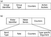
- a group entry of a group tablemay include the following fields.
- a group identifierthat identifies the group entry, a group type that specifies a rule as to whether to perform some or all of the action buckets defined in the group entry, a counter of the flow entry Counters for statistics, and action buckets, which are a set of actions associated with parameters defined for a group.
- the meter tableconsists of meter entries and defines per-flow meters. Per flow meter can allow openflow to apply various QoS operations.
- a meteris a kind of switch element that can measure and control the rate of packets.
- a meter tableincludes a meter identifier for identifying a meter, meter bands indicating a speed designated in a band and a packet operation method, and a packet. It consists of counter fields that are updated when running on the meter.
- Meter bandsare band types that indicate how packets are processed, the rate used to select the meter band by the meter, and counters that are updated when packets are processed by the meter band. ), And fields such as type specific arguments, which are bad types with optional arguments.
- the switch controller 200may typically control the operations of the units to control the overall operation of the switch 20.
- the switch controller 200may include a table management module 240, a flow search module 220, a flow processing module 230, and a packet processing module 235 that manage the table 291.
- Each modulemay be configured in hardware in the controller 200, or may be configured in software separate from the controller 200.
- the table management module 240may add an entry received from the controller 10 through the controller communication unit 210 to an appropriate table or periodically remove an entry timed out.
- the flow search module 220may extract flow information from a packet received as user traffic.
- the flow informationincludes identification information of an ingress port, which is a packet inflow port of an edge switch, identification information of a packet incoming port of a corresponding switch, packet header information (IP address, MAC address, port of source and destination, And VLAN information, etc.), metadata, and the like.
- the metadatamay be optionally added in the previous table or data added in another switch.
- the flow search module 220may search whether there is a flow entry for the received packet in the table 291 with reference to the extracted flow information. When the flow entry is retrieved, the flow retrieval module 220 may request the flow processing module 260 to process the received packet according to the retrieved flow entry. If the flow entry search fails, the flow search module 220 may transmit the received packet or the minimum data of the received packet to the controller 10 through the controller communication unit 210.
- the flow processing module 230may process an action such as outputting, dropping, or modifying a specific header field to a specific port or multiple ports according to the procedure described in the entry retrieved by the flow retrieval module 220. have.
- the flow processing module 230may execute an instruction to process a pipeline entry of a flow entry or change an action, or execute a set of actions when the flow table can no longer go to the next table.
- the packet processing module 235may actually output the packet processed by the flow processing module 230 to one or two or more ports of the port unit 205 designated by the flow processing module 230.
- the SDN network systemmay further include an orchestrator 1.
- the orchestrator 1may create, change, and delete virtual network devices, virtual switches, and the like.
- the orchestrator 1identifies the switch to which the virtual network will connect, the port identification to the switch, the MAC address, the IP address, and the tenant identification.
- Information of the network devicesuch as information and network identification information can be provided to the controller 10.
- the controller 10 and the switch 20communicate with the orchestrator 1 via a separate interface, or the orchestrator 1 through the switch communication unit 110 of the controller 10 and the controller communication unit 210 of the switch 20. ) Can be communicated with.
- the switch 20may exchange messages with the orchestrator 1 through the controller 10.
- the controller 10 and the switch 20exchange various information, which is called an openflow protocol message.
- open flow messagesinclude types such as controller-to-switch messages, asynchronous messages, and symmetric messages.
- Each messagemay have a transaction id (xid) in the header that identifies the entry.
- the controller-switch messageis a message generated by the controller 10 and transmitted to the switch 20, and is mainly used to manage or check the state of the switch 20.
- the controller-switch messagemay be generated by the controller 100 of the controller 10, in particular the message management module 130.
- Controller-switch messagesinclude features for querying the capabilities of the switch, configurations for querying and setting settings for the configuration parameters of the switch 20, flows / groups / meters in the OpenFlow table.
- Status change messagesinclude modify flow table messages, modify flow entry messages, modify group entry messages, port modification messages, and meter entry changes. Message (meter modification message).
- the asynchronous messageis a message generated by the switch 20 and used to update the state of the switch, network events, and the like in the controller 10.
- the asynchronous messagemay be generated by the control unit 200 of the switch 20, in particular the flow retrieval module 220.
- Asynchronous messagesinclude packet-in messages, flow-removed messages, and error messages.
- the packet-in messageis used by the switch 20 to send a packet to the controller 10 to take control of the packet.
- the packet-in messageincludes all or part of a received packet or copy thereof sent from the openflow switch 20 to the controller 10 to request a data path when the switch 20 receives an unknown packet. Is a message.
- Packet-in messagesare also used when the action of an entry associated with an incoming packet is destined to be sent to the controller.
- the deleted flow-removed messageis used to convey to the controller 10 the flow entry information to be deleted in the flow table. This message occurs in the flow expiry process where the controller 10 has requested the switch 20 to delete the corresponding flow entry or because of a flow timeout.
- Symmetric messagesare generated by both the controller 10 and the switch 20, and are transmitted without the request of the other party.
- Helloused to initiate a connection between the controller and the switch, an echo to ensure that there is no problem with the connection between the controller and the switch, and an error message used by the controller or switch to notify the other side of the problem (error message) and the like.
- Error messagesare mostly used in switches to indicate failures in response to requests initiated by the controller.
- FIG. 6is a structural diagram of an IoT network system according to an embodiment of the present invention
- FIG. 7is a block diagram of a common gateway according to an embodiment of the present invention
- FIG. 8is a structural diagram of a service function cloud of FIG. 7.
- 9is an internal block diagram of the cloud switch of FIG. 8
- FIG. 10is a block diagram of the controller of FIG. 7.
- the Internet of Things (IoT) network systemmay include an orchestrator 1, a controller 10, a common gateway 30, and a service function cloud 60.
- the common gateway 30may transmit data collected from various IoT devices 50 to the service function cloud 60 to enable various service operations.
- the IoT open platform 90may collect data processed in the service function cloud 60.
- the IoT open platform 90may provide the collected data directly to customers or as various services.
- the service provided to the customer by the IoT open platform 90may provide data as a service of various protocols by processing data collected by a third party group or the like.
- the IoT open platform 90may provide an IoT application service development environment to anyone through providing an open OS-based platform / SDK.
- the IoT device 50refers to various devices (TVs, refrigerators, cleaners, washing machines, boilers, mobile phones, vending machines, automobiles) or sensor devices to which the Internet of Things (IoT) is applied.
- the IoT device 50is a device with enhanced network function and may include various wired / wireless communication interfaces.
- the IoT device 50may be an IP-based network such as a wireless LAN (Wi-Fi), a wireless broadband (Wibro), a world interoperability for microwave access (Wimax), a high speed downlink packet access (HSDPA), ZigBee, Bluetooth, Radio Frequency Identification (RFID), Infrared Data Association (IrDA), Ultra Wideband (UWB), Near Field Communication (NFC), Cellular Networks, CAN (Controller)
- IP-based networksuch as a wireless LAN (Wi-Fi), a wireless broadband (Wibro), a world interoperability for microwave access (Wimax), a high speed downlink packet access (HSDPA), ZigBee, Bluetooth, Radio Frequency Identification (RFID), Infrared Data Association (IrDA), Ultra Wideband (UWB), Near Field Communication (NFC), Cellular Networks, CAN (Controller)
- IP-based networksuch as a wireless LAN (Wi-Fi), a wireless broadband (Wibro),
- the plurality of IoT devices 50may have various heterogeneous network interfaces.
- Existing IoT gatewayscannot solve network bottlenecks caused by large amounts of data collected from various heterogeneous IoT networks.
- the present inventioncan secure network reliability and secure the timeliness of sensor data through the SDN-based IoT gateway technology.
- flexible network setting and / or operationis essential for integrated management function with the Internet or information transfer and actuator operation between heterogeneous IoT sensor networks, which can be applied through the SDN technology according to the present invention.
- the IoT device 50may include IoT device information such as a device identifier, a device name, a model name, a manufacturer, location information, and device status information.
- the device identifiermay use the MAC address of the IoT device 50.
- the IoT device informationmay be delivered to the common gateway 30 through the traffic delivered to the common gateway 30.
- the common gateway 30may include a gateway communication unit 32 and a gateway switch 34.
- the gateway communication unit 32may include different interface modules for communicating with the plurality of Internet of Things (IoT) devices 50 (51 to 54).
- the gateway communication unit 32may be provided with respective modules 32-1 to 32-4 having a Bluetooth, WiFi, Zigbee, and Z-wave interface.
- the gateway communication unit 32may further include various interface modules.
- the gateway communication unit 32may transfer the packet received from the IoT device 50 to the gateway switch 34 through each interface module 32-1 to 32-4.
- the gateway switch 34is an openflow-based switch and may include all or part of the components of the switch of FIG. 3.
- the gateway switch 34may assign an interface identifier to flows received through the gateway communication unit 32.
- the gateway switch 34can know that a packet enters into any one of the plurality of ports p1 to p4 of the port unit 205.
- Each port p1 to p4 of the port unit 205can know which interface module of the gateway communication unit 32 is connected.
- the gateway switch 34may assign an interface identifier to the flow, corresponding to the incoming port of the flow.
- the gateway switch 34may use metadata of the flow as the interface identifier, or use metadata of the incoming packet or a specific field of the incoming packet as the interface identifier.
- the interface identifiermay be included in the service identifier. Detailed description of the service identifier will be described later.
- the service function cloud 60may provide a series of service functions (SF) to the flow received from the common gateway 30 in response to the interface identifier.
- the service function cloud 60may include a plurality of cloud switches cSW and a plurality of service functions SF1 to SF7.
- the cloud switch cSWmay include all or part of the components of the openflow switch mentioned in FIG. 3.
- the cloud switch cSWmay configure various topologies as shown in FIGS. 8A to 8C.
- all cloud switchesprovide a service function as shown in FIG. 8 (a), or one cloud switch as shown in FIG. 8 (b) provides a common gateway 30 and an IoT open platform 90.
- the remaining cloud switchescan provide service functions, or as shown in FIG. 8C, each of the two cloud switches can be connected to the common gateway 30 and the IoT open platform 90, and the service functions can be provided by the remaining cloud switches. have. Not limited to this, various embodiments may be used.
- the service functionmay be implemented by the network function virtualization (NFv) mentioned in FIG. 1.
- the service functions SF1 to SF7may vary.
- service featuresinclude anti DDoS, intrusion detection / blocking (IDS / IPS), integrated security services, virtual private network services, antivirus, antispam, security services, access management services, firewalls, load balancing, QoS
- DPIdeep packet inspection
- CoAPConstrained Application Protocol
- MQTTMQ Telemetry Transport
- IPv6IPv6, and the like.
- the DPI featureis not yet standardized, so its definition is flexible, but it is generally used as a technology that can examine deep parts of packet contents.
- the DPI functioncan store hundreds of thousands of packets in memory until it has enough information to match the types of packets already identified. Once a new packet matches the packet list already identified by the device, the DPI function knows what application is generating and sending the packet and can apply a rule of whether to allow packet transmission. If the DPI function checks up to the packet header and the payload part and cannot identify the application, the DPI function can examine the pattern of how packets are exchanged between computers.
- the CoAP functionis a low power network protocol designed in the form of a sensor network protocol.
- the CoAP functioncan minimize network overhead by applying binary headers to minimize the load.
- CoAP functionuses UDP based protocol.
- the MQTT featureis a lightweight messaging protocol intended for use in machine-to-machine (M2M) and the Internet of things (IoT). It is designed to be used in low power, low bandwidth environments.
- the IPv6 featureprovides the ability to convert an existing IPv4 addressing scheme into an IPv6 scheme.
- the plurality of cloud switchesmay include a flow entry based on the interface identifier, and may transfer the flow to a specific service function among the plurality of service functions SF1 to SF7 in a specific order according to the interface identifier of the flow.
- the service functionmay be implemented as a network function virtualization (NFv) node.
- the service functionis preferably a network function group.
- the network function groupmay consist of network function virtualizations of the same function.
- NFv nodes of the same functional groupmay be composed of NFv nodes 301 to 304 of the same function. NFv nodes of the same functional group are preferably aggregated to be connected to a logical port of the open flow switch 20 to operate as a network device.
- the port unit 205 of the cloud switch cSWmay include logical ports 205-1 and 205-2.
- the packet processing module 235 of the cloud switch cSWmay include a diverging unit 236 and a converging unit 237.
- the diverging unit 236may transfer a packet flowing from the logical output port 205-1 to any one of the plurality of NFv nodes 301 to 304. As described above, the plurality of NFv nodes 301-304 provide the same network function.
- the converging unit 237may receive a packet processed by any one of the plurality of NFv nodes 301 to 304 and transfer the received packet to the logical input port 205-2. Aggregation of the logical ports 205-1 and 205-2 and the divergence / convergence units 236 and 237 of the cloud switch cSW allows the plurality of NFv 301-304 nodes to be like one NFv node. Can function.
- the packet processing module 235transmits the packet flowing through the logical output port 205-1 of the switch SW2 to an appropriate NFv node among the plurality of NFv 301 ⁇ 304 in consideration of the connection state, traffic state, etc. of the port.
- the diverging unit 236can be controlled.
- the creation and deletion of the NFv connected to the cloud switch cSWmay be executed by the orchestrator 1.
- the orchestrator 1may adjust the number of NFv's belonging to the same functional group connected to the logical port according to the traffic state.
- This logical port and aggregation functionmay cause the controller 10 and the switch SW2 to consider only the NFv type on the packet path. Packet paths and flow entries can be simply described as logical ports of the NFv group of the corresponding function.
- the controller 10may include a switch communication unit 110, a controller control unit 100, and a storage unit 190 communicating with a common gateway 30 and a cloud switch cSW.
- the controller controller 100may include a topology management module 120, a path calculation module 125, a message management module 130, an entry management module 135, and a service function management module 140.
- the description of the components with the same reference numeralsrefer to FIG. 2.
- the service function (SF) management module 140may include a service identifier in a packet-in message received from the common gateway 30 or the cloud switch cSW. May be assigned, or a service identifier may be defined in the flow.
- the SF management module 140may control to provide a series of service functions (service chaining) to the flow in response to the service identifier. Application of the service function of the flow of the SF management module 140 may be assisted by the message management module 130 and / or the entry management module 135.
- the service identifierindicates a type of service that can be provided by the service function cloud 60.
- the service identifiermay include an interface identifier representing a network interface of the IoT device 50, and an IoT device identifier that distinguishes the IoT device 50.
- the service identifiermay further include a service request identifier for requesting a particular service from the IoT device 50. According to a predetermined policy between the IoT device 50 and the controller 10, the IoT device 50 may pre-assign a service request identifier to the packet.
- the service identifiermay further include an order identifier that may be updated based on port information into which a flow flows into the cloud switch cSW.
- the service identifiermay include at least an interface identifier of an interface identifier, an IoT device identifier, a service request identifier, and an order identifier.
- the rest of the service identifier except for the order identifierwill be referred to as a service chain identifier. That is, the service identifier may consist only of the interface identifier, or various combinations may appear, such as an interface identifier / IoT device identifier, an interface identifier / order identifier, an interface identifier / IoT device identifier / order identifier, and the like.
- the method of defining a service identifiermay include a method of allocating a service identifier to a specific field among fields predefined in the packet or adding metadata indicating a service type to the packet.
- the service identifiermay be assigned to either field of metadata of the flow.
- a UDP source addressAs a packet field in which a service identifier is defined, a UDP source address, a virtual local area network (vLAN) field, an eXtendsible vLAN (vxLAN) field, and the like may be used.
- vLANvirtual local area network
- vxLANeXtendsible vLAN
- the field of the flow (or packet) in which the service identifier is definedmay change as the flow passes through the common gateway 30 and / or the plurality of cloud switches cSW.
- the UDP source address field of the packetmay be defined as a service identifier in the common gateway 30, and the incoming port may be redefined as a service identifier in any of the plurality of cloud switches cSW.
- the storage unit 190may store a program for processing and controlling the controller 100.
- the storage unit 190may perform a function for temporarily storing input or output data (packets, messages, etc.).
- the storage unit 190may include an entry DB 191, a service list DB 192, a topology DB 193, an IoT device DB 194, a service DB 195, and a statistics DB 196.
- the topology DB 193may include connection information of the service gateways SF1 to SF7 connected to each of the common gateway 30, the plurality of cloud switches cSW, and the cloud switches cSW by the topology manager 130. Can be.
- the service DB 195may store and manage service entries.
- the service entrymay distinguish a type of service provided by the service function cloud 60.
- the service entrydefines the types of service functions SF1 to SF7 of the service function cloud 60 and may be connected with a service identifier.
- the service list DB 192may store service lists in which a service identifier and service functions are a set.
- the service functions included in the service listconstitute a chain of services, which constitutes a service chaining sequence of services of a particular kind.
- the service listincludes a service identifier and a service chaining as a set.
- the order of the service functionsmay be dynamically changed to reflect the topology state of the service functions, the traffic processing state, or the like.
- the storage or update of the service entry or the service listmay be managed by the SF management module 140.
- the service listmay allow service chaining specific to traffic according to a particular physical layer interface to be configured. For example, when using a UDP source address as a service identifier or an interface identifier, the common gateway 30 allocates 8000 to the UDP source address of the packet of the Bluetooth IoT device, 8001 for WiFi, In the cloud switch (cSW) disposed in the service function cloud 60, the UDP source address may be checked to operate a service chaining specialized for the corresponding interface traffic.
- the controller 10may pre-distribute flow entries to the gateway switch 34 of the common gateway 30 and the cloud switch cSW of the service function cloud 60 to generate such a packet path.
- the IoT device DB 194may store IoT device information.
- the IoT device DB 194may store and manage an IoT device identifier, and the IoT device MAC address may be used.
- Entry DB 191may store and manage entries for the appropriate packet path created based on topology DB 193, service list DB 192, and / or service information DB 195.
- the statistics DB 196may store and manage statistics such as traffic amount, processing speed, number and type of service functions passed through each flow, bandwidth utilization of the IoT device, and harmful traffic information.
- the controller controller 100uses the harmful traffic information of the statistics DB 196 to configure and distribute the flow entry to the open flow switch (gateway switch 34 and / or cloud switch (cSW)) so that specific traffic is blocked.
- the open flow switchgateway switch 34 and / or cloud switch (cSW)
- cSWcloud switch
- traffic of the corresponding Bluetooth devicemay be blocked.
- the service identifiermay be blocked based on the IoT device identifier (MAC address).
- MAC addressIoT device identifier
- a blocking policymay be set for each service used, such as a destination UDP address or a destination TCP address among the service identifiers.
- This filtering functionmay be implemented as a filtering service function in the service function cloud 60 or may be implemented as a flow policy of a cloud switch (cSW).
- the present inventionis not limited thereto, and the filtering function may be implemented in the gateway switch 34 of the common gateway 30.
- the controller controller 100may manage bandwidth resources according to the characteristics of each IoT device 50 based on the bandwidth usage rate of the IoT device of the statistics DB 196. This allows a particular physical layer (communication interface) IoT device to use up all its bandwidth, minimizing the impact on other physical layer IoT devices. As a result, the resources may be equally used for each of the different physical layer IoT devices, or bandwidth resources may be managed according to the characteristics of each IoT device.
- This bandwidth functionmay be implemented as a bandwidth service function in the service function cloud 60 or may be implemented as a flow policy of a cloud switch (cSW). However, the present invention is not limited thereto, and the bandwidth service function may be implemented in the gateway switch 34 of the common gateway 30.
- FIG. 11is a service list database table according to an embodiment of the present invention
- FIG. 12is a structural diagram of a service function cloud according to an embodiment of the present invention
- FIG. 13is a flow table according to FIGS. 11 and 12
- FIG. Iis a structural diagram of a service function cloud according to another embodiment of the present invention
- FIG. 15is a flow table according to FIGS. 11 and 14. See FIGS. 1 to 10.
- the controller 10may generate a table of service lists in which a service chain identifier and a service chaining corresponding to the service chain identifier (a specific combination of a series of service functions and the order thereof) are a set.
- the table according to the present embodimentis a table for applying a service function A to a packet when the service chain identifier is 100 and a service function A, B, and C in order when the service chain identifier is 300.
- the controller 10may derive the path of the packet according to each service chain identifier based on the service list database and the switch topology.
- the controller 10may generate an entry list to be delivered to each openflow switch based on the derived route.
- the controller 10may transmit the generated entry list to the open flow switches of the corresponding path according to the entry list change message.
- Such an entry change messageis preferably transmitted to the open flow switch in advance so that each open flow switch has corresponding entry information. This is because when an open flow switch comes in, a packet can be processed immediately.
- an entry corresponding to a flow that is likely to be of low usageis not proactive, and the entry may be distributed when a packet-in message is received from an openflow switch.
- the controller 10may designate a timeout value of a pre-distributed flow entry as a maximum value or zero. If the timeout value is 0, the OpenFlow switch can persist the entry, regardless of whether the entry is hit or not. At the time of this writing, the OpenFlow Switch White Paper 1.4.0 defines two types of timeout values: idle_timeout and hard_timeout. If you want to make the entry persistent, set both idle_timeout and hard_timeout to zero. If necessary, the controller 10 may send a message to the openflow switch to delete a flow entry designated as 0 or to change to a non-zero timeout value.
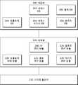
- the service function cloud 60includes a base open flow switch 61 for receiving a packet from the common gateway 30, a service function open flow switch 62 connected to service function nodes, and a plurality of NFv. Groups G1 to G4 may be included. This topology may be similar to FIG. 9 (B).
- the base openflow switch 61 and the service function openflow switch 62are switches of the openflow protocol.
- the base openflow switch 61is an openflow switch directly connected to the common gateway 30 and the IoT open platform 90.
- the base openflow switch 61may be directly connected to a service function node to provide a service function.
- the service function openflow switch 62may be generated by the virtual machine as an openflow switch directly connected to the base openflow switch 61 or connected to another virtual switch, but is not limited thereto and may be an actual physical switch. However, it is preferable that the virtual switch for interworking with the NFv.
- the plurality of NFv groups G1 to G4may provide different functions, that is, different services.
- the plurality of NFv groups G1 to G4may be connected to the service function open flow switch 62 to provide a series of services, that is, service chains, to packets passing through.
- Each NFv groupmay include one or more NFv nodes. As shown in FIG. 9, NFv nodes belonging to an NFv group are preferably aggregated and connected to one logical input / output port of an open flow switch. When NFv nodes belonging to the same group are connected to multiple I / O ports of an open flow switch, packet forwarding, traffic distribution, and load balancing should be controlled or managed through a flow table. It is more advantageous in terms of traffic control or traffic efficiency to load balance with one logical input / output port than load balancing through flow table change.
- the controller 10When the open flow switch 30 (cSW) is powered up (wake up), the controller 10 displays the topology between the switches and the location information of the network devices NFv connected to each switch through a message of the open flow switch. Able to know.
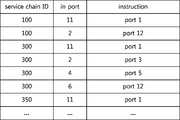
- FIG. 13specifically relates to a flow table of the service function open flow switch 62, which may operate a flow entry having a match field only with information of the service chain identifier and the inflow port.
- the service chain identifieris 100
- outflow ports to which packets are deliveredare determined according to port information into which packets are introduced.
- the service identifierdoes not need to have an order identifier. In this case, memory can be saved, and the time for searching for an entry matching the flow information can be shortened.
- the service function cloud 60includes a base open flow switch 65 for receiving a packet from the common gateway 30, a first and second service function open flow switches 66 connected to service function nodes, 67), and a plurality of NFv groups G1 to G4.
- the service function cloud 60illustrates a case where the number of service function open flow switches is two or more. If there are two or more virtual switches, it is preferable that the service chain identifier has an order identifier as shown in FIG. 15. Hereinafter, the difference from FIG. 12 will be described with emphasis.
- FIG. 15shows a flow table with a service chain identifier of 350 in FIG.
- the cloud openflow switchmay pre-distribute flow entries from the controller 10 and store them in a flow table.
- 15 (a)is a base open flow switch 65
- FIG. 15 (b)is a flow table of a first service function open flow switch 66
- FIG. 15 (c)is a second service function open flow switch 67.
- the service list when the service chain identifier is 350is A-> C-> B when referring to FIG.
- the following problemmay occur when configuring a match field of a flow table using only a service chain identifier and an incoming port. If a packet flows from port 3 of the base openflow switch 65 to port 11 of the first service function openflow switch 66, the packet is sent to either of the NFv groups G1 (service A) and G2 (service B). I don't know what to send to the group. Accordingly, the present invention inserts an updated value (order identifier) into metadata associated with a packet or table when passing through an NFv group or an open flow switch associated with an NFv, so that an accurate output port can be designated.
- the service identifieris composed of a service chain identifier and an order identifier. Some of the fields used as service identifiers are configured as service chain identifiers and others as order identifiers. Thus, even if there are two or more open flow switches directly connected to the NFv group, there is a problem in packet flow. There was no.
- the order identifier updatecan be performed when a packet is leaked to any port of an openflow switch, when a packet is coming from any port, or when a packet is coming from a port connected to another Openflow switch that is directly connected to an NFv group. In either case, or in combination.
- the present inventionis not limited thereto and may correspond to the present invention as long as an order identifier update requirement for accurately specifying a port from which a packet is leaked.
- service chainingoccurs in one open flow switch, such as the service chain identifier 100 or 200 of FIG. 11, it is preferable that the order identifier is not updated so that resource consumption may be reduced.
- the case where the service chain identifier of the packet introduced to the base openflow switch 65 is 350is illustrated according to the flow of the packet.
- the initial value of the order identifieris 0.
- the controller 10generates a flow entry such as (a) to (c) of FIG. 15 based on the packet path to be described later, so that the base open flow switch 65, the first service function open flow switch 66, and The entry creation (change) message may be transmitted to each of the second service function open flow switches 67.
- the base openflow switch 65forwards packets introduced to port 1 to port 3. Since it is the initial path of the service chain identifier, it is irrelevant to the order identifier. Therefore, whether or not the order identifier matches can be omitted. By omitting order identifier matching, the searching time can be shortened.
- the order identifier of the corresponding flow entrymay be implemented by masking.
- the first service function openflow switch 66forwards the packet introduced to the port 11 with the order identifier 0 to the port 1.
- the first service function openflow switch 66forwards the packet flowing into the port 2 to the port 12.
- all packets coming from the NFv groupneed to be forwarded to port 12 of the base openflow switch 65, so the order identifier is masked and the in port is port 2 or 4 You can configure the match field.
- the base openflow switch 65updates the order identifier of the packet introduced to the port 4 whose order identifier is 0 (step 1), and then forwards the packet to the port 5. This is because the packet is coming from an OpenFlow switch that is directly connected to the NFv group.
- the second service function openflow switch 67forwards the packet introduced to port 21 to port 1, and then forwards the packet introduced to port 2 to port 22.
- packet forwardingmay be performed regardless of the order identifier.
- the order identifiermay not be masked to determine whether the order identifier is correct. Referring to FIG. 15 (c), an error search may be performed by matching an order identifier with a flow entry associated with a packet flowing into port 21 of the flow table of the second service function open flow switch 67.
- the base openflow switch 65forwards packets introduced to port 6 to port 3. In this case, since the order identifier is irrelevant, the order identifier field may be masked. However, the base openflow switch 65 must update the order identifier of the packet before forwarding the packet to port 3.
- the first service function openflow switch 66forwards the packet introduced to the port 11 having the order identifier 2 to the port 3.
- the first service function openflow switch 66forwards the packet introduced to port 4 to port 12.
- the order identifieris irrelevant and can be masked.
- the flow entrymay be integrated with a port whose entry port is two.
- the base openflow switch 65forwards the packet introduced to port 4 to port 2 and transmits it to the server. Since the order identifier is no longer used, there is no need to update the order identifier.
- each open flow switchmay receive a corresponding flow entry from the controller 10 in advance and store it in an entry table.
- the present inventionmay be implemented in hardware or software.
- the inventionmay also be embodied as computer readable code on a computer readable recording medium.
- the computer-readable recording mediumincludes all kinds of recording devices in which data that can be read by a computer system is stored. Examples of computer-readable recording media include ROM, RAM, CD-ROM, magnetic tape, floppy disks, optical data storage devices, and the like, which are also implemented in the form of carrier waves (for example, transmission over the Internet). Include.
- the computer readable recording mediumcan also be distributed over network coupled computer systems so that the computer readable code is stored and executed in a distributed fashion. And functional programs, codes and code segments for implementing the present invention can be easily inferred by programmers in the art to which the present invention belongs.
- Embodiments of the present inventionmay include a carrier wave having electronically readable control signals that may be operated with a programmable computer system on which one of the methods described herein is executed.
- Embodiments of the present inventionmay be implemented as a computer program product having a program code, the program code being operated to execute one of the methods when the computer program is run on a computer.
- the program codemay for example be stored on a machine readable carrier.
- One embodiment of the inventionmay be a computer program having program code for executing one of the methods described herein when the computer program is run on a computer.
- the inventionmay include a computer, or a programmable logic device, for performing one of the methods described above. Programmable logic devices (eg, field programmable gate arrays, complementary metal oxide semiconductor based logic circuits) may be used to perform some or all of the functions described above.
- gateway switch 50IoT devices
Landscapes
- Engineering & Computer Science (AREA)
- Computer Networks & Wireless Communication (AREA)
- Signal Processing (AREA)
- Data Exchanges In Wide-Area Networks (AREA)
Abstract
Description
Translated fromKorean본 발명은 사물 인터넷(IoT; Internet of Things)의 패킷 제어를 SDN(Software Defined Network) 기반의 네트워크에서 제어하는 네트워크 시스템에 관한 것으로, 서비스 기능을 가상화하고 일련의 서비스 기능이 적용되도록 하여, 운용의 자동화 및 IoT 장치별로 소프트웨어의 유지/보수 및 업그레이드를 용이하게 할 수 있는 네트워크 시스템에 관한 것이다.The present invention relates to a network system for controlling packet control of the Internet of Things (IoT) in a SDN (Software Defined Network) -based network, and virtualizes a service function and allows a series of service functions to be applied. The present invention relates to a network system that can facilitate maintenance and upgrade of software for each automation and IoT device.
기존 게이트웨이의 경우, IoT 장치의 인터페이스 중심으로 제어 및 관리가 되도록 되어 있다. 이에 IoT 장치의 프로토콜 마다 개별 게이트웨이가 존재해야 한다. IoT 장치들이 통합되어 운영되는 경우 각 장치의 프로토콜 스택들(소프트웨어) 사이에 충돌이 발생하여 게이트웨이의 안전성과 성능에 문제가 있을 수 있다. 또한 IoT 장치별로 소프트웨어 유지/보수 및 업그레이드가 용이하지 않을 수 있다.In the case of the existing gateway, the control and management around the interface of the IoT device. Therefore, an individual gateway must exist for each protocol of the IoT device. When IoT devices are integrated and run, conflicts between protocol stacks (software) of each device may cause problems in the safety and performance of the gateway. In addition, software maintenance and upgrades by IoT devices may not be easy.
<선행기술문헌><Preceding technical literature>
비특허문헌 1. OpenFlow Switch Specification version 1.4.0(Wire Protocol 0x05), October 14, 2013 [https://www.opennetworking.org/images/stories/downloads/sdn-resources/onf-specifications/openflow/openflow-spec-v1.4.0.pdf]Non-Patent
비특허문헌 2. Software-Defined Networking: The New Norm for Netwrks, ONF White Paper, April 13, 2012 [https://www.opennetworking.org/images/stories/downloads/sdn-resources/white-papers/wp-sdn-newnorm.pdf]Non-Patent Document 2: Software-Defined Networking: The New Norm for Netwrks, ONF White Paper, April 13, 2012 [https://www.opennetworking.org/images/stories/downloads/sdn-resources/white-papers/wp -sdn-newnorm.pdf]
비특허문헌 3. ETSI GS NFV 002 v1.1.1 (2013-10)Non-Patent Document 3: ETSI GS NFV 002 v1.1.1 (2013-10)
[http://www.etsi.org/deliver/etsi_gs/NFV/001_099/002/01.01.01_60/gs_NFV002v010101p.pdf][http://www.etsi.org/deliver/etsi_gs/NFV/001_099/002/01.01.01_60/gs_NFV002v010101p.pdf]
본 발명의 목적은 네트워크 인터페이스가 상이한 IoT 장치의 프로토콜을 지원하며, IoT 장치의 네트워크 인터페이스별로 서비스 체이닝을 설정 가능하도록 하는 네트워크 시스템을 제공하는 것이다.An object of the present invention is to provide a network system that supports a protocol of IoT devices having different network interfaces, and enables service chaining to be set for each network interface of the IoT device.
본 발명의 일실시예에 따른 IoT 네트워크 시스템은, 공통 게이트웨이로서, 복수의 IoT(Internet of Things) 장치와 통신하는 서로 다른 인터페이스 모듈을 구비하는 통신부; 및 상기 통신부를 통해 인입한 플로우에 상기 플로우의 패킷이 인입한 인터페이스를 식별하는 인터페이스 식별자를 구비하는 서비스 식별자를 상기 플로우에 할당하는 오픈플로우(openflow) 기반의 게이트웨이 스위치를 구비하는 상기 공통 게이트웨이; 및 상기 공통 게이트웨이로부터 전달받은 플로우에 상기 인터페이스 식별자에 대응하여 인터페이스 별로 일련의 서비스 기능을 제공하는 서비스 기능 클라우드를 포함할 수 있다.An IoT network system according to an embodiment of the present invention, as a common gateway, communication unit having different interface modules for communicating with a plurality of Internet of Things (IoT) devices; And the common gateway having an openflow-based gateway switch for allocating a service identifier having an interface identifier for identifying an interface into which the packet of the flow is introduced into the flow received through the communication unit. And a service function cloud that provides a series of service functions for each interface in response to the interface identifier in the flow received from the common gateway.
본 발명에 따르면, 다양한 프로토콜의 IoT 장치를 통합 지원할 수 있으며, 네트워크 인터페이스별로 가상화된 서비스 기능을 운용할 수 있고, 이에 의해 IoT 장치별로 해당 소프트웨어의 유지 보수를 효율적으로 할 수 있다.According to the present invention, it is possible to integrate and support IoT devices of various protocols, and to operate a virtualized service function for each network interface, thereby efficiently maintaining the corresponding software for each IoT device.
도 1은 본 발명의 일실시예에 따른 SDN 네트워크 시스템의 블록 구성도(block diagram),1 is a block diagram of a SDN network system according to an embodiment of the present invention;
도 2는 도 1의 네트워크 시스템의 제어기의 블록 구성도,2 is a block diagram illustrating a controller of the network system of FIG. 1;
도 3은 도 1의 네트워크 시스템의 스위치의 블록 구성도,3 is a block diagram of a switch of the network system of FIG.
도 4는 플로우 엔트리의 필드 테이블 및 플로우 엔트리에 따른 동작 종류를 나타내는 동작 테이블,4 is an operation table indicating a field table of a flow entry and an operation type according to the flow entry;
도 5는 그룹 및 미터 테이블의 필드 테이블,5 is a field table of a group and a meter table,
도 6은 본 발명의 일 실시예에 따른 IoT 네트워크 시스템의 구조도,6 is a structural diagram of an IoT network system according to an embodiment of the present invention;
도 7은 본 발명의 일 실시예에 따른 공통 게이트웨이의 블록 구성도,7 is a block diagram of a common gateway according to an embodiment of the present invention;
도 8은 도 7의 서비스 기능 클라우드의 구조도,8 is a structural diagram of a service function cloud of FIG. 7;
도 9는 도 8의 클라우드 스위치의 내부 블록 구성도,9 is a block diagram illustrating an internal block of the cloud switch of FIG. 8;
도 10은 도 7의 제어기의 블록 구성도,10 is a block diagram of the controller of FIG. 7;
도 11은 본 발명의 일 실시예에 따른 서비스 리스트 데이터 베이스 테이블,11 is a service list database table according to an embodiment of the present invention;
도 12는 본 발명의 일 실시예에 따른 서비스 기능 클라우드의 구조도,12 is a structural diagram of a service function cloud according to an embodiment of the present invention;
도 13은 도 11 및 도 12에 따른 플로우 테이블,13 is a flow table according to FIGS. 11 and 12;
도 14는 본 발명의 다른 실시예에 따른 서비스 기능 클라우드의 구조도, 및14 is a structural diagram of a service function cloud according to another embodiment of the present invention, and
도 15는 도 11 및 도 14에 따른 플로우 테이블이다.15 is a flow table according to FIGS. 11 and 14.
이하, 도면을 참조하여 본 발명을 보다 상세하게 설명한다.Hereinafter, the present invention will be described in more detail with reference to the drawings.
제1, 제2 등의 용어는 다양한 구성요소들을 설명하는데 사용될 수 있지만, 상기 구성요소들은 상기 용어들에 의해 한정되어서는 안 된다. 상기 용어들은 하나의 구성요소를 다른 구성요소로부터 구별하는 목적으로만 사용된다. 예를 들어, 본 발명의 권리 범위를 벗어나지 않으면서 제1 구성요소는 제2 구성요소로 명명될 수 있고, 유사하게 제2 구성요소도 제1 구성요소로 명명될 수 있다. 및/또는 이라는 용어는 복수의 관련된 기재된 항목들의 조합 또는 복수의 관련된 기재된 항목들 중의 어느 항목을 포함한다.Terms such as first and second may be used to describe various components, but the components should not be limited by the terms. The terms are used only for the purpose of distinguishing one component from another. For example, without departing from the scope of the present invention, the first component may be referred to as the second component, and similarly, the second component may also be referred to as the first component. The term and / or includes a combination of a plurality of related items or any item of a plurality of related items.
어떤 구성요소가 다른 구성요소에 "연결되어" 있다거나 "접속되어" 있다고 언급된 때에는, 그 다른 구성요소에 직접적으로 연결되어 있거나 또는 접속되어 있을 수도 있지만, 중간에 다른 구성요소가 존재할 수도 있다고 이해되어야 할 것이다. 반면에, 어떤 구성요소가 다른 구성요소에 "직접 연결되어" 있다거나 "직접 접속되어" 있다고 언급된 때에는, 중간에 다른 구성요소가 존재하지 않는 것으로 이해되어야 할 것이다. 또한 네트워크 상의 제1 구성요소와 제2 구성요소가 연결되어 있거나 접속되어 있다는 것은, 유선 또는 무선으로 제1 구성요소와 제2 구성요소 사이에 데이터를 주고 받을 수 있음을 의미한다.When a component is referred to as being "connected" or "connected" to another component, it may be directly connected to or connected to that other component, but it may be understood that other components may be present in between. Should be. On the other hand, when a component is said to be "directly connected" or "directly connected" to another component, it should be understood that there is no other component in between. In addition, when the first component and the second component on the network are connected or connected, it means that data can be exchanged between the first component and the second component by wire or wirelessly.
또한, 이하의 설명에서 사용되는 구성요소에 대한 접미사 "모듈" 및 "부"는 단순히 본 명세서 작성의 용이함만이 고려되어 부여되는 것으로서, 그 자체로 특별히 중요한 의미 또는 역할을 부여하는 것은 아니다. 따라서, 상기 "모듈" 및 "부"는 서로 혼용되어 사용될 수도 있다.In addition, the suffixes "module" and "unit" for the components used in the following description are merely given in consideration of ease of preparation of the present specification, and do not give particular meanings or roles by themselves. Therefore, the "module" and "unit" may be used interchangeably.
이와 같은 구성요소들은 실제 응용에서 구현될 때 필요에 따라 2 이상의 구성요소가 하나의 구성요소로 합쳐지거나, 혹은 하나의 구성요소가 2 이상의 구성요소로 세분되어 구성될 수 있다. 도면 전체를 통하여 동일하거나 유사한 구성요소에 대해서는 동일한 도면 부호를 부여하였고, 동일한 도면 부호를 가지는 구성요소에 대한 자세한 설명은 전술한 구성요소에 대한 설명으로 대체되어 생략될 수 있다.Such components may be configured by combining two or more components into one component, or by dividing one or more components into two or more components as necessary when implemented in an actual application. The same reference numerals are given to the same or similar components throughout the drawings, and detailed descriptions of the components having the same reference numerals may be omitted by replacing the descriptions of the aforementioned components.
SDN은 패킷을 전달하는 데이터 플레인과 패킷의 흐름을 제어하는 제어 플레을 분리된 개념이다. SDN에서 패킷이 발생했을 때, 네트워크 장비는 패킷을 어디로 전달할지 SDN 제어 소프트웨어(제어기)에게 물어보고, 그 결과를 반영하여 패킷을 전송하는 경로와 방식을 결정한다. SDN은 이론적인 개념으로, 실제로 적용하기 위해 오픈플로우(Openflow)가 등장하였다. 즉 오픈플로우는 SDN을 구현하기 위해 제정된 표준 인터페이스이다. 오픈플로우는 오픈플로우 제어기와 오픈플로우 스위치로 구성되어, 플로우 정보를 제어하여 패킷의 전달 경로 및 방식을 결정한다. 본 명세서 전반에서, 오픈플로우와 SDN는 서로 동일한 의미로 사용되거나 혼용하여 사용될 수 있다.SDN is a separate concept from the data plane that carries packets and the control plane that controls the flow of packets. When a packet occurs in the SDN, the network equipment asks the SDN control software (controller) where to forward the packet and reflects the result to determine the path and method of transmitting the packet. SDN is a theoretical concept, and Openflow has emerged for practical application. In other words, OpenFlow is a standard interface established to implement SDN. Openflow is composed of an openflow controller and an openflow switch to control flow information to determine the delivery path and method of the packet. Throughout this specification, openflow and SDN may be used interchangeably or in the same sense.
플로우(flow)는 하나의 스위치 관점에서 적어도 하나의 헤더 필드의 값을 공유하는 일련의 패킷들 또는 다중 스위치의 여러 플로우 엔트리(flow entry)들의 조합에 따른 특정 경로의 패킷 흐름을 의미할 수 있다. 오픈플로우 네트워크는 플로우 단위로 경로 제어, 장애 회복, 부하 분산 및 최적화를 행할 수 있다. 본 명세서에서 플로우는 특정 패킷을 의미할 수 있으며, 특정 패킷과 인입 포트 등 다른 메타데이터를 포함하는 것을 의미할 수도 있다.A flow may refer to a packet flow of a specific path according to a combination of a series of packets or multiple flow entries of multiple switches that share a value of at least one header field from one switch perspective. Openflow networks can perform path control, failover, load balancing and optimization on a flow-by-flow basis. In the present specification, a flow may mean a specific packet, and may also include other metadata such as a specific packet and an ingress port.
도 1은 본 발명의 일실시예에 따른 SDN 네트워크 시스템의 블록 구성도(block diagram), 도 2는 도 1의 네트워크 시스템의 제어기의 블록 구성도, 도 3은 도 1의 네트워크 시스템의 스위치의 블록 구성도, 도 4는 플로우 엔트리의 필드 테이블 및 플로우 엔트리에 따른 동작 종류를 나타내는 동작 테이블, 도 5는 그룹 및 미터 테이블의 필드 테이블이다.1 is a block diagram of an SDN network system according to an embodiment of the present invention, FIG. 2 is a block diagram of a controller of the network system of FIG. 1, and FIG. 3 is a block diagram of a switch of the network system of FIG. 4 is an operation table indicating a field table of a flow entry and an operation type according to the flow entry, and FIG. 5 is a field table of a group and a meter table.
도 1(a)를 참조하면, 본 발명에 일 실시예에 따른 SDN 네트워크 시스템은 제어기(contoller)(10), 복수의 스위치(20) 및 복수의 네트워크 디바이스(30)를 포함할 수 있다.Referring to FIG. 1A, an SDN network system according to an embodiment of the present invention may include a
네트워크 디바이스(30)는 데이터나 정보를 주고 받고자 하는 사용자 단말 장치, 또는 특정 기능을 수행하는 물리 장치 또는 가상 장치를 포함할 수 있다. 하드웨어 관점에서, 네트워크 디바이스(30)는 PC, 클라이언트 단말기, 서버, 워크스테이션, 수퍼컴퓨터, 이동통신 단말기, 스마트폰, 스마트패드 등이 있을 수 있다. 또한 네트워크 디바이스(30)는 물리 장치 상에 생성된 가상 머신(VM)일 수 있다.The
네트워크 디바이스(30)는 네트워크 상의 여러가지 기능을 수행하는 네트워크 기능(network function)으로 지칭될 수 있다. 네트워크 기능은 안티(anti) DDoS, 침입 감지/차단(IDS/IPS), 통합 보안 서비스, 가상 사설망 서비스, 안티 바이러스, 안티 스팸, 보안 서비스, 접근관리 서비스, 방화벽, 로드 밸런싱, QoS, 비디오 최적화 등을 포함할 수 있다. 이러한 네트워크 기능은 가상화될 수 있다.The
가상화된 네트워크 기능으로 ETSI(유럽전기통신표준협회)에서 발행한 NFV 관련 백서(비특허문헌 3 참조)에서 정의된 네트워크 기능 가상화(Network Function Virtualiztion; NFV)가 있다. 본 명세서에서 네트워크 기능(NF)은 네트워크 기능 가상화(NFV)와 혼용하여 사용될 수 있다. NFV는 테넌트(tenant)별 필요한 L4-7 서비스 연결을 동적으로 생성하여 필요한 네트워크 기능을 제공하거나, DDoS 공격의 경우 정책 기반으로 필요한 방화벽, IPS 및 DPI 기능 등을 일련의 서비스 체이닝으로 빠르게 제공되는데 이용될 수 있다. 또한 NFV는 방화벽이나 IDS/IPS를 쉽게 온오프 할 수 있으며, 자동으로 프로비저닝(provisioning)할 수 있다. NFV는 오버 프로비저닝의 필요성도 줄일 수 있다.A virtualized network function is the Network Function Virtualization (NFV) defined in the NFV white paper (see Non-Patent Document 3) issued by the ETSI (European Telecommunication Standards Association). Network function (NF) can be used interchangeably with network function virtualization (NFV) herein. NFV dynamically creates the necessary L4-7 service connections per tenant to provide the necessary network functions, or in the case of DDoS attacks, quickly provides the necessary firewall, IPS, and DPI features through a series of service chaining. Can be. In addition, NFV can easily turn on or off firewalls or IDS / IPS and automatically provision them. NFV can also reduce the need for over-provisioning.
제어기(controller)(10)는 SDN 시스템을 제어하는 일종의 지휘 컴퓨터로서, 다양하고 복잡한 기능들, 예를 들어, 라우팅, 정책 선언, 및 보안 체크 등을 할 수 있다. 제어기(10)는 하위 계층의 복수의 스위치(20)에서 발생하는 패킷의 플로우를 정의할 수 있다. 제어기(10)는 네트워크 정책 상 허용되는 플로우에 대해 네트워크 토폴로지 등을 참조하여 플로우가 경유할 경로(데이터 경로)를 계산한 후, 경로 상의 스위치에 상기 플로우의 엔트리가 설정되도록 할 수 있다. 제어기(10)는 특정 프로토콜, 예를 들어, 오픈플로우 프로토콜을 이용하여 스위치(20)와 통신할 수 있다. 제어기(10)와 스위치(20)의 통신 채널은 SSL에 의해 암호화 될 수 있다.The
도 2를 참조하면, 제어기(10)는 스위치(20)와 통신하는 스위치 통신부(110), 제어부(100), 및 저장부(190)를 포함할 수 있다.2, the
저장부(190)는 제어부(100)의 처리 및 제어를 위한 프로그램을 저장할 수 있다. 저장부(190)는 입력되거나 출력되는 데이터들(패킷, 메시지 등)을 임시 저장을 위한 기능을 수행할 수 있다. 저장부(190)는 플로우 엔트리를 저장하는 엔트리 데이터베이스(DB)(191)를 포함할 수 있다.The storage unit 190 may store a program for processing and controlling the
제어부(100)는 통상적으로 상기 각 부의 동작을 제어하여 제어기(10)의 전반적인 동작을 제어할 수 있다. 제어부(100)는 토폴로지 관리 모듈(120), 경로 계산 모듈(125), 엔트리 관리 모듈(135) 및 메시지 관리 모듈(130)을 포함할 수 있다. 각 모듈은 제어부(100) 내에 하드웨어로 구성될 수 있고, 제어부(100)와 별개의 소프트웨어로 구성될 수도 있다.The
토폴로지 관리 모듈(120)은 스위치 통신부(110)를 통하여 수집된 스위치(20)의 접속 관계를 기초로 네트워크 토폴로지 정보를 구축 및 관리 할 수 있다. 네트워크 토폴로지 정보는 스위치들 사이의 토폴로지 및 각 스위치에 연결되어 있는 네트워크 디바이스들의 토폴로지를 포함할 수 있다. 토폴로지 정보는 저장부(190)에 저장될 수 있다.The topology management module 120 may construct and manage network topology information based on a connection relationship of the
경로 계산 모듈(125)은 토폴로지 관리 모듈(120)에서 구축된 네트워크 토폴로지 정보를 기초로 스위치 통신부(110)를 통해 수신한 패킷의 데이터 경로 및 상기 데이터 경로 상의 스위치에서 실행될 액션 열을 구할 수 있다.The path calculation module 125 may obtain a data path of a packet received through the switch communication unit 110 and an action string to be executed in the switch on the data path based on the network topology information constructed by the topology management module 120.
엔트리 관리 모듈(135)는 경로 계산 모듈(125)에서 계산된 결과, QoS 등의 정책, 사용자 지시 등을 기초로 플로우 테이블, 그룹 테이블, 및 미터 테이블 등의 엔트리로서 엔트리 DB(191)에 등록할 수 있다. 엔트리 관리 모듈(135)은 스위치(20)에 미리 각 테이블의 엔트리가 등록되도록 하거나(proactive), 스위치(20)로부터의 엔트리의 추가 또는 갱신 요구에 응답(reactive)할 수 있다. 엔트리 관리 모듈(135)은 필요에 따라 또는 스위치(10)의 엔트리 소멸 메시지 등에 의해 엔트리 DB(191)의 엔트리를 변경하거나 삭제할 수 있다.The entry management module 135 may register with the entry DB 191 as an entry such as a flow table, a group table, and a meter table based on a result calculated by the route calculation module 125, a policy such as QoS, a user indication, and the like. Can be. The entry management module 135 may allow an entry of each table to be registered in advance in the
메시지 관리 모듈(130)은 스위치 통신부(110)를 통해 수신한 메시지를 해석하거나, 스위치 통신부(110)를 통해 스위치로 전송되는 후술할 제어기-스위치 메시지를 생성할 수 있다. 제어기-스위치 메시지 중 하나인 상태 변경 메시지는 엔트리 관리 모듈(135)에 의해 생성된 엔트리 또는 엔트리 DB(191)에 저장된 엔트리에 기초하여 생성될 수 있다.The message management module 130 may interpret a message received through the switch communication unit 110 or generate a controller-switch message to be described later transmitted to the switch through the switch communication unit 110. The state change message, which is one of the controller-switch messages, may be generated based on an entry generated by the entry management module 135 or an entry stored in the entry DB 191.
스위치(20)는 오픈플로우 프로토콜을 지원하는 물리적인 스위치 또는 가상 스위치일 수 있다. 스위치(20)는 수신한 패킷을 처리하여, 네트워크 디바이스(30) 사이의 플로우를 중계할 수 있다. 이를 위해 스위치(20)는 하나의 플로우 테이블 또는 비특허문헌 1에 상술되어 있는 파이프라인(pipeline) 처리를 위해 다중 플로우 테이블을 구비할 수 있다.The
플로우 테이블은 네트워크 디바이스(30)의 플로우를 어떻게 처리할 지의 규칙을 정의한 플로우 엔트리를 포함할 수 있다.The flow table may include a flow entry that defines a rule of how to process the flow of the
스위치(20)는 다중 스위치의 조합에 따른 플로우의 입구 및 출구 측 에지 스위치(edge switch)(ingress switch and egress switch)와 에지 스위치 사이의 코어 스위치(core switch)로 구분될 수 있다.The
도 3을 참조하면, 스위치(20)는 다른 스위치 및/또는 네트워크 디바이스와 통신하는 포트부(205), 제어기(10)와 통신하는 제어기 통신부(210), 스위치 제어부(200), 및 저장부(290)를 포함할 수 있다.Referring to FIG. 3, the
포트부(205)는 스위치 또는 네트워크 디바이스와 연결된 한 쌍의 포트를 다수 구비할 수 있다. 한 쌍의 포트는 하나의 포트로 구현될 수 있다.The
저장부(290)는 스위치 제어부(200)의 처리 및 제어를 위한 프로그램을 저장할 수 있다. 저장부(290)는 입력되거나 출력되는 데이터들(패킷, 메시지 등)을 임시 저장을 위한 기능을 수행할 수 있다. 저장부(290)는 플로우 테이블, 그룹 테이블, 및 미터 테이블 등의 테이블(291)을 구비할 수 있다. 테이블(230) 또는 테이블의 엔트리는 제어기(10)의 메시지에 기초하여 추가, 수정, 삭제될 수 있다. 테이블 엔트리는 스위치(20)에 의해 자체적으로 파기될 수 있다.The storage unit 290 may store a program for processing and controlling the
플로우 테이블은 오픈플로우의 파이프라인(pipeline)을 처리하기 위해 다중 플로우 테이블로 구성될 수 있다. 도 4를 참조하면, 플로우 테이블의 플로우 엔트리는 패킷과 매치하는 조건(대조 규칙)을 기술한 매치 필드(match fields), 우선 순위(priority), 매치되는 패킷이 있는 경우 업데이트되는 카운터(counters), 플로우 엔트리에 매치되는 패킷이 있으면 발생하는 다양한 액션들의 집합인 인스트럭션(instruction), 스위치에서 파기될 시간을 기술하는 타임아웃(timeouts), 제어기에 의해 선택되어지는 오파큐(opaque) 타입으로, 제어기에 의해 플로우 통계, 플로우 변경, 및 플로우 삭제를 필터하기 위해 사용될 수 있으며, 패킷 처리시 사용되지 않는 쿠키(cookie) 등의 튜플(tuple)을 포함할 수 있다.Flow tables can be composed of multiple flow tables to handle the pipeline of OpenFlow. Referring to FIG. 4, a flow entry of a flow table includes match fields describing the conditions (control rules) matching packets, priority, counters updated when there is a match, Instructions, which are a set of various actions that occur when a packet is matched in a flow entry, timeouts describing the time to be discarded from the switch, and an opaque type selected by the controller. And may be used to filter flow statistics, flow changes, and flow deletions, and may include tuples such as cookies that are not used in packet processing.
인스트럭션(instruction)은 다른 플로우 테이블로 패킷을 전달하는 것과 같은 파이프라인 프로세싱을 변경할 수 있다. 또한 인스트럭션은 액션 셋(action set)에 액션을 더하는 액션(action)들의 집합, 또는 패킷에 바로 적용하기 위한 액션들의 리스트를 포함할 수 있다. 액션(action)은 특정 포트로 패킷을 전송하거나, TTL 필드를 감소시키는 것과 같이 패킷을 수정하는 작업을 의미할 수 있다. 액션은 플로우 엔트리와 연관된 인스트럭션 집합의 일부 또는 그룹 엔트리와 연관된 액션 버킷에 속할 수 있다. 액션 셋(action set)은 각 테이블에서 지시된 액션이 누적된 집합을 의미한다. 액션 셋은 매치되는 테이블이 없을 때 수행될 수 있다. 도 5는 플로우 엔트리에 의한 여러 패킷 처리를 예시한다.Instructions can alter pipeline processing, such as forwarding packets to another flow table. Instructions can also include a set of actions that add an action to an action set, or a list of actions to apply directly to a packet. An action may mean an operation of modifying a packet such as transmitting a packet to a specific port or decreasing a TTL field. An action may belong to an action bucket associated with a group entry or part of a set of instructions associated with a flow entry. An action set means a set of accumulated actions indicated in each table. An action set can be performed when no table matches. 5 illustrates various packet processing by flow entries.
파이프라인(pipleline)은 패킷과 플로우 테이블 사이의 일련의 패킷 처리 과정을 의미한다. 스위치(20)에 패킷이 유입되면, 스위치(20)는 첫번째 플로우 테이블의 우선 순위가 높은 순서대로 패킷과 매칭되는 플로우 엔트리를 탐색한다. 매칭이 되면 해당 엔트리의 인스트럭션을 수행한다. 인스트럭션은 매칭되면 바로 수행하는 명령(apply-action), 액션 셋의 내용을 지우거나 추가/수정하는 명령(clear-action; write-action), 메타데이터(metadata) 수정 명령(write-metadata), 지정된 테이블로 메타데이터와 함께 패킷을 이동시키는 고우투 명령(goto-table) 등이 있다. 패킷과 매칭되는 플로우 엔트리가 없는 경우, 테이블 설정에 따라 패킷을 폐기(drop)하거나 제어기(10)로 패킷을 패킷-인 메시지(packet-in message)에 실어서 보낼 수 있다.Pipeline means a series of packet processing between packet and flow table. When a packet enters the
그룹 테이블은 그룹 엔트리들을 포함할 수 있다. 그룹 테이블은 플로우 엔트리에 의해 지시되어 추가적인 포워딩 방법들을 제시할 수 있다. 도 5(a)를 참조하면, 그룹 테이블의 그룹 엔트리는 다음과 같은 필드를 구비할 수 있다. 그룹 엔트리를 구분할 수 있는 그룹 식별자(group identifier), 그룹 엔트리에 정의된 액션 버킷들을 일부(select) 또는 전부(all) 수행할 것이 여부에 대한 규칙을 명시한 그룹 타입(group type), 플로우 엔트리의 카운터와 같이 통계를 위한 카운터(counters), 및 그룹을 위해 정의된 파라미터들과 연관된 액션들의 집합인 액션 버킷(action buckets)을 포함할 수 있다.The group table may include group entries. The group table may be indicated by the flow entry to suggest additional forwarding methods. Referring to FIG. 5A, a group entry of a group table may include the following fields. A group identifier that identifies the group entry, a group type that specifies a rule as to whether to perform some or all of the action buckets defined in the group entry, a counter of the flow entry Counters for statistics, and action buckets, which are a set of actions associated with parameters defined for a group.
미터 테이블(meter table)은 미터 엔트리들(meter entries)로 구성되며, 플로우 미터-당(per-flow meters)을 정의한다. 플로우 미터-당은 오픈플로우가 다양한 QoS 작동을 적용될 수 있도록 할 수 있다. 미터(meter)는 패킷의 레이트(rate of packets)를 측정 및 제어할 수 있는 일종의 스위치 요소이다. 도 5(b)를 참조하면, 미터 테이블(meter table)은 미터를 식별하는 미터 식별자(meter identifier), 밴드(band)에 지정된 속도와 패킷 동작 방법을 나타내는 미터 밴드(meter bands), 및 패킷이 미터에서 동작될 때 업데이트되는 카운터(counters) 필드들로 구성된다. 미터 밴드(meter bands)는 패킷이 어떻게 처리되는 지를 나타내는 밴드 타입(band type), 미터에 의해 미터 밴드를 선택하는데 사용되는 레이트(rate), 미터 밴드에 의해 패킷들이 처리될 때 업데이트되는 카운터(counters), 및 선택적인 아규먼트(argument)를 가지는 배드 타입들인 특정 아규먼트 타입(type specific argument)과 같은 필드들로 구성될 수 있다.The meter table consists of meter entries and defines per-flow meters. Per flow meter can allow openflow to apply various QoS operations. A meter is a kind of switch element that can measure and control the rate of packets. Referring to FIG. 5 (b), a meter table includes a meter identifier for identifying a meter, meter bands indicating a speed designated in a band and a packet operation method, and a packet. It consists of counter fields that are updated when running on the meter. Meter bands are band types that indicate how packets are processed, the rate used to select the meter band by the meter, and counters that are updated when packets are processed by the meter band. ), And fields such as type specific arguments, which are bad types with optional arguments.
스위치 제어부(200)는 통상적으로 상기 각 부의 동작을 제어하여 스위치(20)의 전반적인 동작을 제어할 수 있다. 스위치 제어부(200)는 테이블(291)을 관리하는 테이블 관리 모듈(240), 플로우 검색 모듈(220), 플로우 처리 모듈(230), 및 패킷 처리 모듈(235)를 포함할 수 있다. 각 모듈은 제어부(200) 내에 하드웨어로 구성될 수 있고, 제어부(200)와 별개의 소프트웨어로 구성될 수도 있다.The
테이블 관리 모듈(240)은 제어기 통신부(210)를 통해 제어기(10)로부터 수신한 엔트리를 적절한 테이블에 추가하거나, 타임 아웃(time out)된 엔트리를 주기적으로 제거할 수 있다.The table management module 240 may add an entry received from the
플로우 검색 모듈(220)은 유저 트래픽으로서 수신한 패킷으로부터 플로우 정보를 추출할 수 있다. 플로우 정보는 에지 스위치의 패킷 유입 포트인 입구 포트(ingress port)의 식별 정보, 해당 스위치의 패킷 유입 포트(incoming port)의 식별 정보, 패킷 헤더 정보(송신원 및 목적지의 IP 주소, MAC 주소, 포트, 및 VLAN 정보 등), 및 메타데이터 등을 포함할 수 있다. 메타데이터는 이전 테이블에서 선택적으로 추가되거나, 다른 스위치에서 추가된 데이터일 수 있다. 플로우 검색 모듈(220)은 추출한 플로우 정보를 참조하여 테이블(291)에 수신 패킷에 대한 플로우 엔트리가 있는지 검색할 수 있다. 플로우 검색 모듈(220)은 플로우 엔트리가 검색되면, 플로우 처리 모듈(260)에 검색된 플로우 엔트리에 따라 수신 패킷을 처리하도록 요청할 수 있다. 만일 플로우 엔트리 검색이 실패하면, 플로우 검색 모듈(220)은 수신 패킷 또는 수신 패킷의 최소한의 데이터를 제어기 통신부(210)를 통해 제어기(10)로 전송할 수 있다.The
플로우 처리 모듈(230)는 플로우 검색 모듈(220)에서 검색된 엔트리에 기술된 절차에 따라 패킷을 특정 포트 또는 다중 포트로 출력하거나, 드롭시키거나 또는 특정 헤더 필드를 수정하는 등의 액션을 처리할 수 있다.The flow processing module 230 may process an action such as outputting, dropping, or modifying a specific header field to a specific port or multiple ports according to the procedure described in the entry retrieved by the
플로우 처리 모듈(230)는 플로우 엔트리의 파이프라인 프로세스를 처리하거나 액션을 변경하기 위한 인스트럭션을 실행하거나 다중 플로우 테이블에서 더 이상 다음 테이블로 갈 수 없을 때 액션 세트를 실행할 수 있다.The flow processing module 230 may execute an instruction to process a pipeline entry of a flow entry or change an action, or execute a set of actions when the flow table can no longer go to the next table.
패킷 처리 모듈(235)은 플로우 처리 모듈(230)에 의해 처리된 패킷을 플로우 처리 모듈(230)에서 지정한 포트부(205)의 하나 또는 2 이상의 포트로 실제로 출력할 수 있다.The
도 1(b)를 참조하면, SDN 네트워크 시스템은 오케스트레이터(1)를 더 포함할 수 있다. 오케스트레이터(1)는 가상 네트워크 디바이스, 가상 스위치 등을 생성, 변경 및 삭제할 수 있다. 오케스트레이터(1)에서 가상 네트워크 디바이스를 생성하는 경우, 오케스트레이터(1)는 가상 네트워크가 접속할 스위치의 식별 정보, 해당 스위치에 연결되는 포트 식별 정보, MAC 주소, IP 주소, 터넨트(tenant) 식별 정보 및 네트워크 식별 정보 등의 네트워크 디바이스의 정보를 제어기(10)로 제공할 수 있다.Referring to FIG. 1 (b), the SDN network system may further include an
제어기(10) 및 스위치(20)는 오케스트레이터(1)와 별도의 인터페이스로 통신하거나, 제어기(10)의 스위치 통신부(110) 및 스위치(20)의 제어기 통신부(210)를 통해 오케스트레이터(1)와 통신할 수 있다. 스위치(20)는 제어기(10)를 통해 오케스트레이터(1)와 메시지를 주고 받을 수 있다.The
제어기(10)와 스위치(20)는 다양한 정보를 주고 받는데, 이를 오픈플로우 프로토콜 메시지(openflow protocol message)라 칭한다. 이러한 오픈플로우 메시지는 제어기-스위치 메시지(controller-to-switch message), 비동기 메시지(asynchronous message), 및 대칭 메시지(symmetric message) 등의 타입이 있다. 각 메시지는 엔트리를 식별하는 트랜잭션 식별자(transaction id; xid)를 헤더에 구비할 수 있다.The
제어기-스위치 메시지는 제어기(10)가 생성하여 스위치(20)에 전달하는 메시지로써, 주로 스위치(20)의 상태를 관리하거나 점검하기 위해 사용된다. 제어기-스위치 메시지는 제어기(10)의 제어부(100), 특히 메시지 관리 모듈(130)에 의해 생성될 수 있다.The controller-switch message is a message generated by the
제어기-스위치 메시지는 스위치의 능력(capabilities)을 문의하는 기능(features), 스위치(20)의 구성 매개 변수 등의 설정을 문의하고 설정하기 위한 설정(configuration), 오픈플로우 테이블의 플로우/그룹/미터 엔트리들을 추가/삭제/수정하기 위한 상태 변경 메시지(modify state message), 패킷-인 메시지를 통해 스위치로부터 수신한 패킷을 해당 스위치 상의 특정한 포트로 전송하도록 하는 패킷-아웃 메시지(packet-out message) 등이 있다. 상태 변경 메시지는 플로우 테이블 변경 메시지(modify flow table message), 플로우 엔트리 변경 메시지(modify flow entry message), 그룹 엔트리 변경 메시지(modify group entry message), 포트 변경 메시지(prot modification message), 및 미터 엔트리 변경 메시지(meter modification message) 등이 있다.Controller-switch messages include features for querying the capabilities of the switch, configurations for querying and setting settings for the configuration parameters of the
비동기 메시지는 스위치(20)가 생성하는 메시지로서, 스위치의 상태 변경 및 네트워크 이벤트 등을 제어기(10)에서 업테이트하기 위해 사용된다. 비동기 메시지는 스위치(20)의 제어부(200), 특히 플로우 검색 모듈(220)에 의해 생성될 수 있다.The asynchronous message is a message generated by the
비동기 메시지로 패킷-인 메시지(packet-in message), 플로우 삭제 메시지(flow-removed), 에러 메시지 등이 있다. 패킷-인 메시지는 스위치(20)가 제어기(10)에게 패킷을 전송하여 패킷에 대한 제어를 받기 위해 사용된다. 패킷-인 메시지는 스위치(20)가 미지의 패킷을 수신한 경우, 데이터 경로를 요구하기 위해, 오픈플로우 스위치(20)에서 제어기(10)로 전송되는 수신 패킷 또는 그 사본의 전부 또는 일부를 포함하는 메시지이다. 유입 패킷에 연관된 엔트리의 액션이 제어기로 보내라고 정해져 있을 때에도 패킷-인 메시지가 사용된다. 삭제된 플로우(flow-removed) 메시지는 플로우 테이브에서 삭제할 플로우 엔트리 정보를 제어기(10)로 전달하기 위해 사용된다. 이 메시지는 제어기(10)가 스위치(20)에 해당 플로우 엔트리 삭제를 요청하였거나 플로우 타임아웃(timeout)에 의한 플로우 만기 처리(flow expiry process)에서 발생한다.Asynchronous messages include packet-in messages, flow-removed messages, and error messages. The packet-in message is used by the
대칭 메시지는 제어기(10) 및 스위치(20) 모두에서 생성되며, 상대방의 요청이 없어도 전송되는 특징이 있다. 제어기와 스위치 간에 연결을 개시할 때 사용되는 헬로(hello), 제어기 및 스위치 간 연결에 이상이 없음을 확인하기 위한 에코(echo), 및 제어기나 스위치에 의해 사용되며 문제를 반대측에 알리기 위한 에러 메시지(error message) 등을 포함할 수 있다. 에러 메시지는 대부분 제어기에 의해 개시된 요청에 따른 실패를 나타나기 위해 스위치에서 사용된다.Symmetric messages are generated by both the
도 6은 본 발명의 일 실시예에 따른 IoT 네트워크 시스템의 구조도, 도 7은 본 발명의 일 실시예에 따른 공통 게이트웨이의 블록 구성도, 도 8은 도 7의 서비스 기능 클라우드의 구조도, 도 9는 도 8의 클라우드 스위치의 내부 블록 구성도, 및 도 10은 도 7의 제어기의 블록 구성도이다.6 is a structural diagram of an IoT network system according to an embodiment of the present invention, FIG. 7 is a block diagram of a common gateway according to an embodiment of the present invention, and FIG. 8 is a structural diagram of a service function cloud of FIG. 7. 9 is an internal block diagram of the cloud switch of FIG. 8, and FIG. 10 is a block diagram of the controller of FIG. 7.
도 6을 참조하면, 본 실시예에 따른 IoT(Internet of Things) 네트워크 시스템은 오케스트레이터(1), 제어기(10), 공통 게이트웨이(30), 및 서비스 기능 클라우드(60)을 포함할 수 있다.Referring to FIG. 6, the Internet of Things (IoT) network system according to the present embodiment may include an
공통 게이트웨이(30)는 다양한 IoT 장치(50)로부터 수집되는 데이터를 서비스 기능 클라우드(60)로 전송하여 다양한 서비스 운용이 가능하도록 할 수 있다. IoT 오픈 플랫폼(90)은 서비스 기능 클라우드(60)에서 처리된 데이터를 취합할 수 있다. IoT 오픈 플랫폼(90)은 취합한 데이터를 고객에게 직접 제공하거나 다양한 서비스로 제공할 수 있다. IoT 오픈 플랫폼(90)이 고객에게 제공하는 서비스는 제3자 그룹(3rd party) 등이 취합된 데이터를 가공하여 다양한 프로토콜의 서비스로 고객에게 제공할 수 있다. IoT 오픈 플랫폼(90)은 개방형 OS 기반 플랫폼/SDK 제공을 통해 누구에게나 IoT 응용 서비스 개발 환경을 제공할 수 있다.The
IoT 장치(50)는 사물 인터넷(IoT; Internet of Things)이 적용된 다양한 장치(TV, 냉장고, 청소기, 세탁기, 보일러, 휴대폰, 자판기, 자동차)나 센서 장치를 의미한다. IoT 장치(50)는 네트워크 기능이 강화된 장치로, 다양한 유/무선 통신 인터페이스를 구비할 수 있다. 예를 들어, IoT 장치(50)는 WLAN(Wireless LAN)(Wi-Fi), Wibro(Wireless broadband), Wimax(World Interoperability for Microwave Access), HSDPA(High Speed Downlink Packet Access) 등의 IP 기반 네트워크, 지그비(ZigBee), 블루투스(Bluetooth), RFID(Radio Frequency Identification), 적외선 통신(IrDA, infrared Data Association), UWB(Ultra Wideband), NFC(Near Field Communication), 셀룰러 네트워크(Cellular networks), CAN(Controller Area Networks) 등의 비 IP 기반 네트워크를 사용할 수 있다.The
복수의 IoT 장치(50)는 위에서 언급한 바와 같이, 다양한 이기종의 네트워크 인터페이스를 가질 수 있다. 기존 IoT 게이트웨이는 다양한 이종 IoT 망으로부터 수집되는 대량 데이터로 인한 네트워크 병목 현상을 해소하기 어렵다. 이에 본 발명은 SDN 기반의 IoT 게이트웨이 기술을 통해, 네트워크 신뢰성 확보 및 센서 데이터의 시의성 확보를 할 수 있다. 또한, 인터넷과의 통합 관리 기능이나 이종 IoT 센서 네트워크 사이의 정보 전달 및 액츄에이터 동작을 위해서는 유연한 네트워크 설정 및/또는 운용이 필수적인데, 이는 본 발명에 따른 SDN 기술을 통해 적용할 수 있다.As mentioned above, the plurality of
IoT 장치(50)는 장치 식별자, 장치명, 모델명, 제조사, 위치정보, 장치상태 정보 등의 IoT 장치 정보를 구비할 수 있다. 장치 식별자는 IoT 장치(50)의 MAC 주소가 사용될 수 있다. 이러한 IoT 장치 정보는 공통 게이트웨이(30)로 전달되는 트래픽을 통해 공통 게이트웨이(30)로 전달될 수 있다.The
도 7을 참조하면, 공통 게이트웨이(30)는 게이트웨이 통신부(32) 및 게이트웨이 스위치(34)를 포함할 수 있다.Referring to FIG. 7, the
게이트웨이 통신부(32)는 복수의 IoT(Internet of Things) 장치(50; 51~54)와 통신하는 서로 다른 인터페이스 모듈을 구비할 수 있다. 게이트웨이 통신부(32)는 블루투스, WiFi, 지그비, 및 Z-wave 인터페이스를 가지는 각각의 모듈(32-1 ~ 32-4)을 구비할 수 있다. 게이트웨이 통신부(32)는 이 외에도 다양한 인터페이스 모듈을 구비할 수 있다.The gateway communication unit 32 may include different interface modules for communicating with the plurality of Internet of Things (IoT) devices 50 (51 to 54). The gateway communication unit 32 may be provided with respective modules 32-1 to 32-4 having a Bluetooth, WiFi, Zigbee, and Z-wave interface. The gateway communication unit 32 may further include various interface modules.
게이트웨이 통신부(32)는 각 인터페이스 모듈(32-1 ~ 32-4)을 통해 IoT 장치(50)로부터 수신한 패킷을 게이트웨이 스위치(34)로 전달할 수 있다.The gateway communication unit 32 may transfer the packet received from the
게이트웨이 스위치(34)는 오픈플로우(openflow) 기반의 스위치로, 도 3의 스위치의 구성 요소 전부 또는 그 일부를 구비할 수 있다.The
게이트웨이 스위치(34)는 게이트웨이 통신부(32)를 통해 인입한 플로우에 인터페이스 식별자를 할당할 수 있다. 게이트웨이 스위치(34)는 포트부(205)의 복수의 포트(p1 ~ p4) 중 어느 포트로 패킷이 인입하는 알 수 있다. 포트부(205)의 각 포트(p1 ~ p4)는 게이트웨이 통신부(32)의 어느 인터페이스 모듈과 연결되어 있는 지 알 수 있다. 따라서, 게이트웨이 스위치(34)는 플로우의 인입 포트에 대응하여, 인터페이스 식별자를 플로우에 할당할 수 있다. 게이트웨이 스위치(34)는 플로우의 메타데이터를 인터페이스 식별자로 사용하거나, 인입 패킷의 메타데이터 또는 인입 패킷의 특정 필드를 인터페이스 식별자로 사용할 수 있다. 인터페이스 식별자는 서비스 식별자에 포함될 수 있다. 서비스 식별자에 대한 자세한 설명은 후술한다.The
서비스 기능 클라우드(60)는 인터페이스 식별자에 대응하여, 공통 게이트웨이(30)로부터 전달 받은 플로우에 일련의 서비스 기능(SF; Service Function)을 제공할 수 있다. 도 8를 참조하면, 서비스 기능 클라우드(60)는 복수의 클라우드 스위치(cSW) 및 복수의 서비스 기능(SF1 ~ SF7)을 구비할 수 있다.The
클라우드 스위치(cSW)는 도 3에서 언급한 오픈플로우 스위치의 구성요소 전부 또는 그 일부를 포함할 수 있다. 클라우드 스위치(cSW)는 도 8(a) 내지 도 8(c)와 같이, 다양한 토폴로지를 구성할 수 있다. 복수의 클라우드 스위치(cSW)는 도 8(a)와 같이 모든 클라우드 스위치가 서비스 기능을 제공하거나, 도 8(b)와 같이 하나의 클라우드 스위치가 공통 게이트웨이(30) 및 IoT 오픈 플랫폼(90)을 연결하고 나머지 클라우드 스위치가 서비스 기능을 제공하거나, 도 8(c)와 같이 두 개의 클라우드 스위치 각각이 공통 게이트웨이(30) 및 IoT 오픈 플랫폼(90)과 연결되고 나머지 클라우드 스위치에서 서비스 기능을 제공할 수 있다. 이에 한정되지 않고, 다양한 실시례가 사용될 수 있다.The cloud switch cSW may include all or part of the components of the openflow switch mentioned in FIG. 3. The cloud switch cSW may configure various topologies as shown in FIGS. 8A to 8C. In the plurality of cloud switches cSW, all cloud switches provide a service function as shown in FIG. 8 (a), or one cloud switch as shown in FIG. 8 (b) provides a
서비스 기능은 도 1에서 언급한 가상 네트워크 기능(NFv; Network Function Virtualization)에 의해 구현될 수 있다. 서비스 기능(SF1 ~ SF7)은 다양할 수 있다. 예를 들어, 서비스 기능은 안티(anti) DDoS, 침입 감지/차단 (IDS/IPS), 통합 보안 서비스, 가상 사설망 서비스, 안티 바이러스, 안티 스팸, 보안 서비스, 접근관리 서비스, 방화벽, 로드 밸런싱, QoS, 비디오 최적화 등 이외에, 심층 패킷 분석(DPI; Deep Packet Inspection), CoAP (Constrained Application Protocol), MQTT(MQ Telemetry Transport), IPv6 등이 있다.The service function may be implemented by the network function virtualization (NFv) mentioned in FIG. 1. The service functions SF1 to SF7 may vary. For example, service features include anti DDoS, intrusion detection / blocking (IDS / IPS), integrated security services, virtual private network services, antivirus, antispam, security services, access management services, firewalls, load balancing, QoS In addition to video optimization, deep packet inspection (DPI), Constrained Application Protocol (CoAP), MQ Telemetry Transport (MQTT), IPv6, and the like.
DPI 기능은 아직까지 표준화된 기술이 아니어서 그 정의가 유동적이나 일반적으로 패킷의 콘텐츠가 담긴 심층부분까지 검사할 수 있는 기술로 통용된다. DPI 기능은 이미 식별된 패킷의 종류에 매칭시킬 수 있는 충분한 정보를 가질 때까지 수십만의 패킷을 메모리에 저장할 수 있다. 일단 새로운 패킷이 이미 장비에 의해 식별된 패킷 리스트에 매칭되면, DPI 기능은 무슨 애플리케이션이 패킷을 생성하고 보내는지를 알게 되고 패킷 전송을 허용할지 말지의 규칙을 적용할 수 있다. 만일 DPI 기능이 패킷 헤더와 페이로드 부분까지 검사를 해도 애플리케이션을 식별할 수 없으면, DPI 기능은 컴퓨터간에 패킷이 어떻게 교환되는지 그 패턴을 검토할 수 있다.The DPI feature is not yet standardized, so its definition is flexible, but it is generally used as a technology that can examine deep parts of packet contents. The DPI function can store hundreds of thousands of packets in memory until it has enough information to match the types of packets already identified. Once a new packet matches the packet list already identified by the device, the DPI function knows what application is generating and sending the packet and can apply a rule of whether to allow packet transmission. If the DPI function checks up to the packet header and the payload part and cannot identify the application, the DPI function can examine the pattern of how packets are exchanged between computers.
CoAP 기능은 센서 네트워크 프로토콜 형식으로 디자인된 저전력용 네트크 프로토콜이다. CoAP 기능은 부하를 최대한 줄이기 위해 바이너리 헤더를 적용하여 네트워크 오버헤드를 최소할 시킬 수 있다. CoAP 기능은 UDP 기반의 프로토콜을 사용한다. MQTT 기능은 경량의 메시징 프로토콜로, M2M(machine-to-machine)와 IoT(Internet of things)에서의 사용을 목적으로 만들었다. 이를 위해서 낮은 전력, 낮은 대역폭 환경에서도 사용할 수 있도록 설계됐다. IPv6 기능은 기존의 IPv4 주소 체계를 IPv6 체계로 변환하는 기능을 제공한다.The CoAP function is a low power network protocol designed in the form of a sensor network protocol. The CoAP function can minimize network overhead by applying binary headers to minimize the load. CoAP function uses UDP based protocol. The MQTT feature is a lightweight messaging protocol intended for use in machine-to-machine (M2M) and the Internet of things (IoT). It is designed to be used in low power, low bandwidth environments. The IPv6 feature provides the ability to convert an existing IPv4 addressing scheme into an IPv6 scheme.
복수의 클라우드 스위치은 인터페이스 식별자에 기반한 플로우 엔트리를 구비하여, 플로우의 인터페이스 식별자에 따라 플로우를 복수의 서비스 기능(SF1 ~ SF7) 중 특정 서비스 기능에 특정 순서로 전달할 수 있다.The plurality of cloud switches may include a flow entry based on the interface identifier, and may transfer the flow to a specific service function among the plurality of service functions SF1 to SF7 in a specific order according to the interface identifier of the flow.
이와 같이 서비스 기능 클라우드(60)의 서비스 기능으로 가상화로 인하여, IoT 장치별로 소프트웨어 어플리케이션의 유지 보수 및 업그레이드를 용이하게 할 수 있다.As such, due to virtualization as a service function of the
도 9는 특히, 서비스 기능을 제공하는 클라우드 스위치의 내부의 일부 블록 구성도이다. 앞서 설명한 바와 같이, 서비스 기능은 네트워크 기능 가상화(NFv; Network Function Virturalisatoin) 노드로 구현될 수 있다. 서비스 기능은 네트워크 기능 그룹인 것이 바람직하다. 네트워크 기능 그룹은 동일한 기능의 네트워크 기능 가상화들로 구성될 수 있다.9 is a block diagram of some of the internal parts of a cloud switch that provides a service function. As described above, the service function may be implemented as a network function virtualization (NFv) node. The service function is preferably a network function group. The network function group may consist of network function virtualizations of the same function.
도 9를 참조하면, 동일 기능 그룹의 NFv 노드들은 동일한 기능의 NFv 노드들(301 ~ 304)로 구성될 수 있다. 동일 기능 그룹의 NFv 노드들은 오픈플로우 스위치(20)의 논리 포트에 연결되어 하나의 네트워크 디바이스처럼 작동되도록 집성(aggregation)화 되어 있는 것이 바람직하다.Referring to FIG. 9, NFv nodes of the same functional group may be composed of
클라우드 스위치(cSW)의 포트부(205)는 논리 포트(205-1, 205-2)를 포함할 수 있다. 클라우드 스위치(cSW)의 패킷 처리 모듈(235)은 발산 유닛(236) 및 수렴 유닛(237)을 포함할 수 있다.The
발산 유닛(236)은 논리 출력 포트(205-1)에서 유입되는 패킷을 복수의 NFv 노드(301~304) 중 어느 하나로 전달할 수 있다. 앞서 설명한 바와 같이, 복수의 NFv 노드(301~304)는 동일한 네트워크 기능을 제공한다. 수렴 유닛(237)은 복수의 NFv 노드(301~304) 중 어느 한 노드에서 처리된 패킷을 수신하여, 수신한 패킷을 논리 입력 포트(205-2)로 전달할 수 있다. 클라우드 스위치(cSW)의 논리 포트(205-1, 205-2) 및 발산/수렴 유닛(236, 237)의 집성화 기능(aggregation)은 복수의 NFv(301~304) 노드가 하나의 NFv 노드 처럼 기능하도록 할 수 있다.The diverging
패킷 처리 모듈(235)은 스위치 SW2의 논리 출력 포트(205-1)를 통해 유입되는 패킷을 포트의 연결 상태, 트랙픽 상태 등을 고려하여 복수의 NFv(301~304) 중 적절한 NFv 노드로 전달되도록 발산 유닛(236)을 제어할 수 있다.The
클라우드 스위치(cSW)에 연결되는 NFv의 생성 및 삭제는 오케스트레이터(1)에 의해 실행될 수 있다. 오케스트레이터(1)는 트래픽 상태 등에 따라 논리 포트에 연결되는 동일 기능 그룹에 속한 NFv들의 개수를 조정할 수 있다.The creation and deletion of the NFv connected to the cloud switch cSW may be executed by the
이러한 논리 포트 및 집성 기능은 제어기(10) 및 스위치 SW2가 패킷 경로 상의 NFv 타입만 고려하게 할 수 있다. 패킷 경로 및 플로우 엔트리 등은 해당 기능의 NFv 그룹의 논리 포트로 간단히 기술될 수 있다.This logical port and aggregation function may cause the
도 10을 참조하면, 제어기(10)는 공통 게이트웨이(30) 및 클라우드 스위치(cSW)와 통신하는 스위치 통신부(110), 제어기 제어부(100), 및 저장부(190)를 포함할 수 있다. 제어기 제어부(100)는 토폴로지 관리 모듈(120), 경로 계산 모듈(125), 메시지 관리 모듈(130), 엔트리 관리 모듈(135), 및 서비스 기능 관리 모듈(140)을 구비할 수 있다. 동일한 도면 부호에 대한 구성요소의 설명은 도 2를 참조한다.Referring to FIG. 10, the
서비스 기능(SF; Service Function) 관리 모듈(이하, 'SF 관리 모듈')(140)은 공통 게이트웨이(30) 또는 클라우드 스위치(cSW)로부터 수신한 패킷-인 메시지(packet-in message)에 서비스 식별자를 할당하거나, 플로우에 서비스 식별자가 정의되도록 제어할 수 있다. SF 관리 모듈(140)은 서비스 식별자에 대응하여 플로우에 일련의 서비스 기능(서비스 체이닝; service chaining)이 제공되도록 제어할 수 있다. SF 관리 모듈(140)의 플로우의 서비스 기능 적용은 메시지 관리 모듈(130) 및/또는 엔트리 관리 모듈(135)에 의해 보조될 수 있다.The service function (SF) management module (hereinafter referred to as 'SF management module') 140 may include a service identifier in a packet-in message received from the
서비스 식별자는 서비스 기능 클라우드(60)에서 제공할 수 있는 서비스의 타입을 나타낸다. 서비스 식별자는 IoT 장치(50)의 네트워크 인터페이스를 나타내는 인터페이스 식별자, 및 IoT 장치(50)를 구별하는 IoT 장치 식별자를 포함할 수 있다.The service identifier indicates a type of service that can be provided by the
서비스 식별자는 IoT 장치(50)에서 특별히 특정 서비스를 요청하는 서비스 요청 식별자를 더 포함할 수 있다. IoT 장치(50)와 제어기(10)와의 기설정된 정책에 따라, IoT 장치(50)에서 패킷에 서비스 요청 식별자를 미리 할당할 수 있다.The service identifier may further include a service request identifier for requesting a particular service from the
서비스 식별자는 클라우드 스위치(cSW)에 플로우가 유입되는 포트 정보에 기반하여 업데이트될 수 있는 오더 식별자를 더 포함할 수 있다.The service identifier may further include an order identifier that may be updated based on port information into which a flow flows into the cloud switch cSW.
서비스 식별자는 위에서 언급했듯이, 인터페이스 식별자, IoT 장치 식별자, 서비스 요청 식별자, 및 오더 식별자 중 적어도 인터페이스 식별자를 포함할 수 있다. 본 명세서 전반에서 서비스 식별자 중 오더 식별자를 제외한 나머지를 서비스 체인 식별자로 칭하기로 한다. 즉 서비스 식별자는 인터페이스 식별자로만 구성되거나, 인터페이스 식별자/IoT 장치 식별자, 인터페이스 식별자/오더 식별자, 인터페이스 식별자/IoT 장치 식별자/오더 식별자 등과 같이 여러 조합이 나올 수 있다.As mentioned above, the service identifier may include at least an interface identifier of an interface identifier, an IoT device identifier, a service request identifier, and an order identifier. Throughout this specification, the rest of the service identifier except for the order identifier will be referred to as a service chain identifier. That is, the service identifier may consist only of the interface identifier, or various combinations may appear, such as an interface identifier / IoT device identifier, an interface identifier / order identifier, an interface identifier / IoT device identifier / order identifier, and the like.
서비스 식별자의 정의 방법은, 패킷에 미리 정의 되어 있는 필드 중 특정 필드에 서비스 식별자를 할당하거나, 패킷에 서비스 종류를 나타내는 메타데이터를 추가하는 방법을 포함할 수 있다. 서비스 식별자는 플로우의 메타데이터 중 어느 한 필드에 할당될 수도 있다.The method of defining a service identifier may include a method of allocating a service identifier to a specific field among fields predefined in the packet or adding metadata indicating a service type to the packet. The service identifier may be assigned to either field of metadata of the flow.
서비스 식별자가 정의될 패킷 필드는 UDP 소스(source) 주소, vLAN(virtual Local Area Network) 필드, vxLAN(eXtendsible vLAN) 필드 등이 사용될 수 있다.As a packet field in which a service identifier is defined, a UDP source address, a virtual local area network (vLAN) field, an eXtendsible vLAN (vxLAN) field, and the like may be used.
서비스 식별자가 정의된 플로우(또는 패킷)의 필드는 플로우가 공통 게이트웨이(30) 및/또는 복수의 클라우드 스위치(cSW)를 지나가면서 변경될 수 있다. 예를 들어, 공통 게이트웨이(30)에서 패킷의 UDP 소스 주소 필드를 서비스 식별자로 정의되고, 복수의 클라우드 스위치(cSW) 중 어느 스위치에서는 인입 포트를 서비스 식별자로 재정의되어 사용될 수 있다.The field of the flow (or packet) in which the service identifier is defined may change as the flow passes through the
저장부(190)는 제어부(100)의 처리 및 제어를 위한 프로그램을 저장할 수 있다. 저장부(190)는 입력되거나 출력되는 데이터들(패킷, 메시지 등)을 임시 저장을 위한 기능을 수행할 수 있다. 저장부(190)는 엔트리 DB(191), 서비스 리스트 DB(192), 토폴로지 DB(193), IoT 장치 DB(194), 서비스 DB(195), 및 통계 DB(196)를 포함할 수 있다.The storage unit 190 may store a program for processing and controlling the
토폴로지 DB(193)는 토폴로지 관리부(130)에 의한 공통 게이트웨이(30), 복수의 클라우드 스위치(cSW), 클라우드 스위치(cSW)들 각각에 연결된 서비스 기능들(SF1 ~ SF7)의 연결 정보를 포함할 수 있다.The topology DB 193 may include connection information of the service gateways SF1 to SF7 connected to each of the
서비스 DB(195)는 서비스 엔트리를 저장 및 관리할 수 있다. 서비스 엔트리는 서비스 기능 클라우드(60)에서 제공하는 서비스의 타입을 구분하도록 할 수 있다. 서비스 엔트리는 서비스 기능 클라우드(60)의 서비스 기능(SF1 ~ SF7)의 종류를 정의하며, 서비스 식별자와 연결될 수 있다.The service DB 195 may store and manage service entries. The service entry may distinguish a type of service provided by the
서비스 리스트 DB(192)는 서비스 식별자와 서비스 기능들을 한 집합으로 하는 서비스 리스트들을 저장할 수 있다. 서비스 리스트에 포함된 서비스 기능들은 일련의 서비스들로 특정 종류의 서비스들이 순서를 가지는 서비스 체이닝을 구성한다. 즉 서비스 리스트는 서비스 식별자와 서비스 체이닝을 하나의 집합으로 한다.The service list DB 192 may store service lists in which a service identifier and service functions are a set. The service functions included in the service list constitute a chain of services, which constitutes a service chaining sequence of services of a particular kind. In other words, the service list includes a service identifier and a service chaining as a set.
서비스 기능들의 순서는 서비스 기능들의 토폴로지 상태나 트래픽 처리 상태 등을 반영하여 동적으로 변경될 수 있다. 서비스 엔트리나 서비스 리스트의 저장이나 업데이트는 SF 관리 모듈(140)에 의해 관리될 수 있다.The order of the service functions may be dynamically changed to reflect the topology state of the service functions, the traffic processing state, or the like. The storage or update of the service entry or the service list may be managed by the
서비스 리스트는 특정 물리 계층 인터페이스에 따른 트래픽에 특화된 서비스 체이닝이 구성되도록 할 수 있다. 예를 들어, 서비스 식별자 또는 인터페이스 식별자로 UDP 소스 주소를 사용하는 경우, 공통 게이트웨이(30)에서 블루트스 IoT 장치의 패킷의 UDP 소스 주소에 8000번으로 할당하고, WiFi의 경우 8001을 할당되도록 하고, 서비스 기능 클라우드(60)에 배치된 클라우드 스위치(cSW)에서 UDP 소스 주소를 체크하여 해당 인터페이스 트래픽에 특화된 서비스 체이닝을 운용할 수 있다. 이러한 패킷 경로가 발생되도록 제어기(10)는 공통 게이트웨이(30)의 게이트웨이 스위치(34) 및 서비스 기능 클라우드(60)의 클라우드 스위치(cSW)에 플로우 엔트리를 미리 배포할 수 있다.The service list may allow service chaining specific to traffic according to a particular physical layer interface to be configured. For example, when using a UDP source address as a service identifier or an interface identifier, the
IoT 장치 DB(194)는 IoT 장치 정보를 저장할 수 있다. IoT 장치 DB(194)는 특히 IoT 장치 식별자를 저장 관리할 수 있으며, IoT 장치 식별자는 IoT 장치의 MAC 주소가 이용될 수 있다.The IoT device DB 194 may store IoT device information. In particular, the IoT device DB 194 may store and manage an IoT device identifier, and the IoT device MAC address may be used.
엔트리 DB(191)는 토폴로지 DB(193), 서비스 리스트 DB(192), 및/또는 서비스 정보 DB(195)를 기초로 작성된 적절한 패킷 경로에 대한 엔트리들을 저장 및 관리할 수 있다.Entry DB 191 may store and manage entries for the appropriate packet path created based on topology DB 193, service list DB 192, and / or service information DB 195.
통계 DB(196)는 각 플로우 마다의 트래픽 양, 처리 속도, 경유한 서비스 기능의 개수 및 그 타입, IoT 장치의 대역폭 사용률, 유해 트래픽 정보 등의 통계를 저장 및 관리할 수 있다.The statistics DB 196 may store and manage statistics such as traffic amount, processing speed, number and type of service functions passed through each flow, bandwidth utilization of the IoT device, and harmful traffic information.
제어기 제어부(100)는 통계 DB(196)의 유해 트랙픽 정보를 이용하여, 특정 트래픽이 차단되도록 플로우 엔트리를 구성 및 오픈플로우 스위치(게이트웨이 스위치(34) 및/또는 클라우드 스위치(cSW))에 배포할 수 있다. 예를 들어, 특정 블루투스를 사용하는 IoT 장치로부터 유해 트래픽이 감지된 경우, 해당 블루투스 장치의 트래픽을 차단시킬 수 있다. 이 경우, 서비스 식별자 중 IoT 장치 식별자(MAC 주소)를 기반으로 차단되도록 할 수 있다. 또는 서비스 식별자 중 목적지 UDP 주소, 또는 목적지 TCP 주소와 같이 사용되는 서비스 별로 차단 정책이 설정될 수도 있다. 이러한 필터링 기능은 서비스 기능 클라우드(60)에서 필터링 서비스 기능으로 구현되거나, 클라우드 스위치(cSW)의 플로우 정책으로 구현될 수 있다. 다만 이에 한정되지 않고, 필터링 기능은 공통 게이트웨이(30)의 게이트웨이 스위치(34)에서 구현될 수도 있다.The
제어기 제어부(100)는 통계 DB(196)의 IoT 장치의 대역폭 사용률에 기반하여 각 IoT 장치(50)의 특성에 맞게 대역폭 자원이 관리되도록 할 수 있다. 이는 특정 물리 계층(통신 인터페이스) IoT 장치가 대역폭을 모두 사용하여, 다른 물리 계층 IoT 장치에 영향을 최소로 미치게 할 수 있다. 이에 의해, 서로 다른 물리 계층 IoT 장치들 각각에 자원을 공평하게 사용할 수 있도록 하거나, 각 IoT 장치의 특성에 맞게 대역폭 자원이 관리 될 수 있다. 이러한 대역폭 기능은 서비스 기능 클라우드(60)에서 대역폭 서비스 기능으로 구현되거나, 클라우드 스위치(cSW)의 플로우 정책으로 구현될 수 있다. 다만 이에 한정되지 않고, 대역폭 서비스 기능은 공통 게이트웨이(30)의 게이트웨이 스위치(34)에서 구현될 수도 있다.The
도 11은 본 발명의 일 실시예에 따른 서비스 리스트 데이터 베이스 테이블, 도 12는 본 발명의 일 실시예에 따른 서비스 기능 클라우드의 구조도, 도 13은 도 11 및 도 12에 따른 플로우 테이블, 도 14는 본 발명의 다른 실시예에 따른 서비스 기능 클라우드의 구조도, 도 15는 도 11 및 도 14에 따른 플로우 테이블이다. 도 1 내지 도 10을 참조한다.11 is a service list database table according to an embodiment of the present invention, FIG. 12 is a structural diagram of a service function cloud according to an embodiment of the present invention, FIG. 13 is a flow table according to FIGS. 11 and 12, and FIG. Is a structural diagram of a service function cloud according to another embodiment of the present invention, and FIG. 15 is a flow table according to FIGS. 11 and 14. See FIGS. 1 to 10.
도 11을 참조하면, 제어기(10)는 서비스 체인 식별자와 해당 서비스 체인 식별자에 해당하는 서비스 체이닝(일련의 서비스 기능들의 특정 조합 및 그 순서)을 하나의 집합으로 하는 서비스 리스트들의 테이블을 생성할 수 있다. 예를 들어, 본 실시예에 따른 테이블은 서비스 체인 식별자가 100이면 패킷이 서비스 기능 A가 적용되도록 하며, 서비스 체인 식별자가 300이면 서비스 기능 A, B, 및 C 순으로 적용되도록 하는 테이블이다.Referring to FIG. 11, the
제어기(10)는 서비스 리스트 데이터베이스 및 스위치 토폴로지에 기초하여, 각 서비스 체인 식별자에 따른 패킷의 경로를 도출할 수 있다. 제어기(10)는 도출된 경로에 기초하여, 각 오픈플로우 스위치에 전달될 엔트리 리스트를 생성할 수 있다. 제어기(10)는 생성된 엔트리 리스트를 해당 경로의 오픈플로우 스위치들에 엔트리 리스트에 따른 엔트리 변경 메시지를 전송할 수 있다. 이러한 엔트리 변경 메시지는 오픈플로우 스위치에 미리 전송하여, 각 오픈플로우 스위치가 해당 엔트리 정보를 가지게 하는 것이 바람직하다. 오픈플로우 스위치에서 패킷이 유입되면 즉시 처리할 수 있기 때문이다. 경우에 따라서는 사용률이 적을 것 같은 플로우에 해당하는 엔트리는 선-배포(proactive)하지 않고, 오픈플로우 스위치로부터 패킷-인 메시지를 수신한 경우에 해당 엔트리를 배포할 수도 있다.The
제어기(10)는 선 배포하는 플로우 엔트리의 타임아웃 값을 최대값 또는 0으로 지정할 수 있다. 타임아웃 값이 0인 경우 오픈플로우 스위치는 해당 엔트리의 히트(hit) 여부와 무관하게 엔트리가 존속할 수 있어, 영구 배포가 가능하다. 본 명세서가 작성되는 시점의 오픈플로우 스위치 백서 1.4.0은 타임아웃 값으로 idle_timeout 및 hard_timeout의 두 종류를 정의하고 있다. 엔트리가 영구 존속되도록 설정하려는 경우, idle_timeout 및 hard_timeout 모두 0으로 지정한다. 필요에 의해 제어기(10)는 0으로 지정된 플로우 엔트리를 삭제하거나 0이 아닌 타임아웃 값으로 변경하는 메시지를 오픈플로우 스위치로 전송할 수 있다.The
도 12를 참조하면, 서비스 기능 클라우드(60)는 공통 게이트웨이(30)로부터 패킷을 수신하는 베이스 오픈플로우 스위치(61), 서비스 기능 노드들과 연결된 서비스 기능 오픈플로우 스위치(62), 및 복수의 NFv 그룹(G1~G4)를 포함할 수 있다. 본 토폴로지는 도 9(B)와 유사할 수 있다.Referring to FIG. 12, the
베이스 오픈플로우 스위치(61) 및 서비스 기능 오픈플로우 스위치(62)는 오픈플로우 프로토콜의 스위치이다. 베이스 오픈플로우 스위치(61)는 공통 게이트웨이(30) 및 IoT 오픈 플랫폼(90)에 직접 연결된 오픈플로우 스위치이다. 베이스 오픈플로우 스위치(61)는 직접 서비스 기능 노드가 연결되어, 서비스 기능을 제공 할 수도 있다.The base openflow switch 61 and the service function openflow switch 62 are switches of the openflow protocol. The base openflow switch 61 is an openflow switch directly connected to the
서비스 기능 오픈플로우 스위치(62)는 베이스 오픈플로우 스위치(61)와 직접 또는 다른 가상 스위치와 연결된 오픈플로우 스위치로 가상 머신에 의해 생성될 수 있으나, 이에 한정되지 않고 실제 물리적인 스위치일 수도 있다. 다만 NFv와의 연동을 위해 가상 스위치인 것이 바람직하다.The service function openflow switch 62 may be generated by the virtual machine as an openflow switch directly connected to the base openflow switch 61 or connected to another virtual switch, but is not limited thereto and may be an actual physical switch. However, it is preferable that the virtual switch for interworking with the NFv.
복수의 NFv 그룹(G1~G4)는 각기 다른 기능, 즉 서로 다른 서비스를 제공할 수 있다. 복수의 NFv 그룹(G1~G4)은 서비스 기능 오픈플로우 스위치(62)에 연결되어, 통과하는 패킷에 일련의 서비스 즉 서비스 체인을 제공할 수 있다. 각 NFv 그룹은 하나 이상의 NFv 노드를 포함할 수 있다. 도 9와 같이, NFv 룹에 속한 NFv 노드들은 오픈플로우 스위치의 하나의 논리 입출력 포트로 집성(aggregation) 되어 연결되어 있는 것이 바람직하다. 동일 그룹에 속한 NFv 노드들이 오픈플로우 스위치의 여러 입출력 포트에 연결되어 있는 경우, 패킷 포워딩, 트래픽 분배, 로드 밸런싱 등이 플로우 테이블을 통해 제어 또는 관리되어야 한다. 플로우 테이블 변경을 통해 로드 밸런싱 등을 하는 것 보다 하나의 논리 입출력 포트로 로드 밸런싱 등을 하는 것이, 트래픽 제어 또는 트래픽 효율 등의 면에서 더 유리하다.The plurality of NFv groups G1 to G4 may provide different functions, that is, different services. The plurality of NFv groups G1 to G4 may be connected to the service function open flow switch 62 to provide a series of services, that is, service chains, to packets passing through. Each NFv group may include one or more NFv nodes. As shown in FIG. 9, NFv nodes belonging to an NFv group are preferably aggregated and connected to one logical input / output port of an open flow switch. When NFv nodes belonging to the same group are connected to multiple I / O ports of an open flow switch, packet forwarding, traffic distribution, and load balancing should be controlled or managed through a flow table. It is more advantageous in terms of traffic control or traffic efficiency to load balance with one logical input / output port than load balancing through flow table change.
제어기(10)는 오픈플로우 스위치(30, cSW)가 구동(power on; wake up)되면, 오픈플로우 스위치의 메시지를 통해, 스위치 간의 토폴로지 및 각 스위치에 연결된 네트워크 디바이스들(NFv)의 위치 정보를 알 수 있다.When the open flow switch 30 (cSW) is powered up (wake up), the
도 13은 특히 서비스 기능 오픈플로우 스위치(62)의 플로우 테이블에 관한 것으로, 서비스 기능 오픈플로우 스위치(62)는 서비스 체인 식별자와 유입 포트의 정보만으로 매치 필드를 가지는 플로우 엔트리를 운용할 수 있다. 도 11과 같이, 서비스 체인 식별자가 100인 경우, 패킷이 유입되는 포트 정보에 따라 패킷이 전달될 유출 포트가 각기 정해진다. 본 실시예와 같이 서비스 기능 노드들이 하나의 서비스 기능 오픈플로우 스위치(62)에 연결되어 있는 경우, 서비스 식별자는 오더 식별자를 구비할 필요가 없다. 이 경우, 메모리를 절약할 수 있으며, 플로우 정보에 매칭하는 엔트리를 검색하는 시간을 단축할 수 있다.13 specifically relates to a flow table of the service function open flow switch 62, which may operate a flow entry having a match field only with information of the service chain identifier and the inflow port. As shown in FIG. 11, when the service chain identifier is 100, outflow ports to which packets are delivered are determined according to port information into which packets are introduced. When service function nodes are connected to one service function open flow switch 62 as in this embodiment, the service identifier does not need to have an order identifier. In this case, memory can be saved, and the time for searching for an entry matching the flow information can be shortened.
도 14를 참조하면, 서비스 기능 클라우드(60)는 공통 게이트웨이(30)로부터 패킷을 수신하는 베이스 오픈플로우 스위치(65), 서비스 기능 노드들과 연결된 제1 및 제2 서비스 기능 오픈플로우 스위치(66, 67), 및 복수의 NFv 그룹(G1~G4)를 포함할 수 있다. 도 9의 서비스 기능 클라우드(60)과 비교하면, 본 실시예에 따른 서비스 기능 클라우드(60)은 서비스 기능 오픈플로우 스위치의 개수가 2 이상인 경우를 예시한다. 가상 스위치가 2 이상인 경우, 도 15와 같이 서비스 체인 식별자는 오더 식별자를 구비해야 하는 것이 바람직하다. 이하, 도 12와의 차이점을 중점으로 기술한다.Referring to FIG. 14, the
도 15는, 도 11의 서비스 체인 식별자가 350인 플로우 테이블을 도시하고 있다. 클라우드 오픈플로우 스위치는 제어기(10)로부터 플로우 엔트리를 미리 배포 받아, 플로우 테이블로 저장할 수 있다. 도 15(a)는 베이스 오픈플로우 스위치(65), 도15(b)는 제1 서비스 기능 오픈플로우 스위치(66), 도 15(c)는 제2 서비스 기능 오픈플로우 스위치(67)의 플로우 테이블을 예시한다.FIG. 15 shows a flow table with a service chain identifier of 350 in FIG. The cloud openflow switch may pre-distribute flow entries from the
서비스 체인 식별자가 350인 경우의 서비스 리스트는 도 11을 참조하면, A -> C -> B 이다. 서비스 체인 식별자 및 인입 포트만으로 플로우 테이블의 매치 필드를 구성하는 경우 다음과 같은 문제점이 발생할 수 있다. 패킷이 베이스 오픈플로우 스위치(65)의 3번 포트에서 제1 서비스 기능 오픈플로우 스위치(66)의 11번 포트로 유입되는 경우, 패킷을 NFv 그룹 G1(서비스 A) 및 G2(서비스 B) 중 어느 그룹으로 보내야할지 알 수 없다. 이에 본 발명은 NFv와 관련된 오픈플로우 스위치 또는 NFv 그룹을 통과할 때, 업데이트되는 값(오더 식별자)을 패킷 또는 테이블과 관련된 메타데이터에 삽입하여 정확한 출력 포트를 지정할 수 있도록 하였다. 즉 서비스 식별자를 서비스 체인 식별자와 오더 식별자로 구성하여, 서비스 식별자로 사용되는 필드 중 일부는 서비스 체인 식별자로 나머지는 오더 식별자로 구성하여, NFv 그룹와 직접 연결된 오픈플로우 스위치가 2 이상이어도 패킷 흐름에 지장이 없도록 하였다.The service list when the service chain identifier is 350 is A-> C-> B when referring to FIG. The following problem may occur when configuring a match field of a flow table using only a service chain identifier and an incoming port. If a packet flows from
오더 식별자 업데이트는 오픈플로우 스위치의 임의의 포트로 패킷이 유출될 때, 임의의 포트에서 패킷이 유입될 때, 및 NFv 그룹과 직접 연결되어 있는 다른 오픈플로우 스위치와 연결된 포트에서 패킷이 유입될 때 중 어느 한 경우 또는 조합으로 실행되도록 할 수 있다. 다만 이에 한정되지 않고, 패킷이 유출될 포트를 정확히 지정할 수 있는 오더 식별자 업데이트 요건이면 본 발명에 해당할 수 있다. 메모리 절약, 오더 식별자 업데이트 실행회수의 최소화 등을 위해, NFv 그룹과 직접 연결되어 있는 다른 오픈플로우 스위치에 연결된 포트에서 패킷이 업데이트되는 경우에 오더 식별자를 업데이트하는 것이 바람직하다. 아울러 도 11의 서비스 체인 식별자 100 또는 200과 같이, 하나의 오픈플로우 스위치에서 서비스 체이닝이 일어날 경우, 오더 식별자 업데이트는 이루어지지 않도록 하는 것이 자원 소모를 줄일 수 있어서 바람직하다.The order identifier update can be performed when a packet is leaked to any port of an openflow switch, when a packet is coming from any port, or when a packet is coming from a port connected to another Openflow switch that is directly connected to an NFv group. In either case, or in combination. However, the present invention is not limited thereto and may correspond to the present invention as long as an order identifier update requirement for accurately specifying a port from which a packet is leaked. In order to save memory, minimize order identifier update times, etc., it is desirable to update the order identifier when a packet is updated on a port connected to another openflow switch directly connected to the NFv group. In addition, when service chaining occurs in one open flow switch, such as the
구체적으로 베이스 오픈플로우 스위치(65)에 유입된 패킷의 서비스 체인 식별자가 350인 경우를 패킷의 흐름에 따라 예시한다. 오더 식별자의 초기값은 0으로 한다. 제어기(10)는 후술할 패킷 경로를 기초로 도 15의 (a) 내지 (c)와 같은 플로우 엔트리를 생성하여, 베이스 오픈플로우 스위치(65), 제1 서비스 기능 오픈플로우 스위치(66), 및 제2 서비스 기능 오픈플로우 스위치(67) 각각에 엔트리 생성(변경) 메시지를 전송할 수 있다.Specifically, the case where the service chain identifier of the packet introduced to the
우선 베이스 오픈플로우 스위치(65)는 1번 포트로 유입된 패킷을 3번 포트로 포워딩한다. 해당 서비스 체인 식별자의 초기 경로이므로, 오더 식별자와 무관하다. 이에 오더 식별자의 매칭 여부는 생략할 수 있다. 오더 식별자 매칭 생략을 통해, 검색 시간을 단축시킬 수 있다. 이와 대응하는 플로우 엔트리의 오더 식별자는 마스크하여 구현될 수 있다.First, the base openflow switch 65 forwards packets introduced to
제1 서비스 기능 오픈플로우 스위치(66)는 오더 식별자가 0인 11번 포트로 유입된 패킷을 1번 포트로 포워딩한다. 제1 서비스 기능 오픈플로우 스위치(66)는 2번 포트로 유입된 패킷을 12번 포트로 포워딩한다. 해당 서비스 체인 식별자의 경우, NFv 그룹에서 유입되는 모든 패킷은 베이스 오픈플로우 스위치(65)의 12번 포트로 포워딩하면 되므로, 오더 식별자는 마스킹하고 인입 포트(in port)는 2번 또는 4번 포트로 매치 필드를 구성할 수 있다.The first service function openflow switch 66 forwards the packet introduced to the
베이스 오픈플로우 스위치(65)는 오더 식별자가 0인 4번 포트로 유입된 패킷의 오더 식별자를 업데이트(1단계 상승)한 후, 패킷을 5번 포트로 포워딩한다. NFv 그룹과 직접 연결되어 있는 오픈플로우 스위치에서 인입된 패킷이기 때문이다.The base openflow switch 65 updates the order identifier of the packet introduced to the
제2 서비스 기능 오픈플로우 스위치(67)는 21번 포트로 유입된 패킷을 1번 포트로 포워딩한 후, 2번 포트로 유입된 패킷을 22번 포트로 포워딩한다. 해당 서비스 체인 식별자의 경우, 오더 식별자와 무관하게 패킷 포워딩을 할 수 있다. 다만 패킷 흐름에 에러가 있는 지 판단하기 위한 요건으로, 오더 식별자가 정확한지 판단하기 위해 오더 식별자를 마스크하지 않을 수도 있다. 도 15(c)를 참조하면, 제2 서비스 기능 오픈플로우 스위치(67)의 플로우 테이블 중 21번 포트로 유입되는 패킷과 관련된 플로우 엔트리에 오더 식별자가 매치되도록 하여 에러 탐색을 할 수 있도록 하였다.The second service function openflow switch 67 forwards the packet introduced to
베이스 오픈플로우 스위치(65)는 6번 포트로 유입된 패킷을 3번 포트로 포워딩한다. 이 경우 오더 식별자는 무관하므로, 오더 식별자 필드는 마스킹할 수 있다. 다만 베이스 오픈플로우 스위치(65)는 패킷을 3번 포트로 포워딩하기 전에 해당 패킷의 오더 식별자를 업데이트해야 한다.The base openflow switch 65 forwards packets introduced to
제1 서비스 기능 오픈플로우 스위치(66)는 오더 식별자가 2인 11번 포트로 유입된 패킷을 3번 포트로 포워딩한 한다. 제1 서비스 기능 오픈플로우 스위치(66)는 4번 포트로 유입된 패킷을 12번 포트로 포워딩한다. 이 경우, 오더 식별자는 무관하므로 마스킹할 수 있다. 앞서 서술한 바와 같이, 해당 플로우 엔트리는 인입 포트가 2번인 포트와 통합될 수 있다.The first service function openflow switch 66 forwards the packet introduced to the
베이스 오픈플로우 스위치(65)는 4번 포트로 유입된 패킷을 2번 포트로 포워딩하여 서버로 전송한다. 더 이상 오더 식별자가 사용되지 않으므로, 오더 식별자를 업데이트할 필요는 없다.The base openflow switch 65 forwards the packet introduced to
위에 설명한 바와 같이, 각 오픈플로우 스위치는 제어기(10)로부터 해당 플로우 엔트리를 미리 배포받아, 엔트리 테이블로 저장할 수 있다.As described above, each open flow switch may receive a corresponding flow entry from the
상기 본 발명은 하드웨어 또는 소프트웨어에서 구현될 수 있다. 구현은 상기 본 발명은 또한 컴퓨터로 읽을 수 있는 기록매체에 컴퓨터가 읽을 수 있는 코드로서 구현하는 것이 가능하다. 컴퓨터가 읽을 수 있는 기록매체는 컴퓨터 시스템에 의하여 읽혀질 수 있는 데이터가 저장되는 모든 종류의 기록장치를 포함한다. 컴퓨터가 읽을 수 있는 기록매체의 예로는 ROM, RAM, CD-ROM, 자기 테이프, 플로피 디스크, 광 데이터 저장장치 등이 있으며, 또한 캐리어 웨이브(예를 들어 인터넷을 통한 전송)의 형태로 구현되는 것도 포함한다. 또한 컴퓨터가 읽을 수 있는 기록매체는 네트워크로 연결된 컴퓨터 시스템에 분산되어, 분산방식으로 컴퓨터가 읽을 수 있는 코드가 저장되고 실행될 수 있다. 그리고 본 발명을 구현하기 위한 기능적인(functional) 프로그램, 코드 및 코드 세그먼트들은 본 발명이 속하는 기술분야의 프로그래머들에 의해 용이하게 추론될 수 있다.The present invention may be implemented in hardware or software. The invention may also be embodied as computer readable code on a computer readable recording medium. The computer-readable recording medium includes all kinds of recording devices in which data that can be read by a computer system is stored. Examples of computer-readable recording media include ROM, RAM, CD-ROM, magnetic tape, floppy disks, optical data storage devices, and the like, which are also implemented in the form of carrier waves (for example, transmission over the Internet). Include. The computer readable recording medium can also be distributed over network coupled computer systems so that the computer readable code is stored and executed in a distributed fashion. And functional programs, codes and code segments for implementing the present invention can be easily inferred by programmers in the art to which the present invention belongs.
본 발명의 실시예들은 여기에 설명된 방법들 중 하나가 실행되는 프로그램가능 컴퓨터 시스템으로 운영될 수 있는, 전자적으로 판독가능한 제어 신호들을 갖는 캐리어 웨이브를 포함할 수 있다. 본 발명의 실시예들은 프로그램 코드를 갖는 컴퓨터 프로그램 제품으로서 구현될 수 있으며, 프로그램 코드는 컴퓨터 프로그램이 컴퓨터 상에서 구동될 때 방법들 중 하나를 실행하기 위하여 운영된다. 프로그램 코드는 예를 들면 기계 판독가능 캐리어 상에 저장될 수 있다. 본 발명의 일실시예는 컴퓨터 프로그램이 컴퓨터 상에 구동될 때, 여기에 설명된 방법들 중 하나를 실행하기 위한 프로그램 코드를 갖는 컴퓨터 프로그램일 수 있다. 본 발명은 위에서 설명한 방법들 중 하나를 실행하기 위한 컴퓨터, 또는 프로그램가능 논리 장치를 포함할 수 있다. 위에서 설명한 방법들의 일부 또는 모든 기능을 실행하기 위하여 프로그램가능 논리 장치(예를 들면, 필드 프로그램가능 게이트 어레이, 상보성 금속 산화물 반도체 기반 논리 회로)가 사용될 수 있다.Embodiments of the present invention may include a carrier wave having electronically readable control signals that may be operated with a programmable computer system on which one of the methods described herein is executed. Embodiments of the present invention may be implemented as a computer program product having a program code, the program code being operated to execute one of the methods when the computer program is run on a computer. The program code may for example be stored on a machine readable carrier. One embodiment of the invention may be a computer program having program code for executing one of the methods described herein when the computer program is run on a computer. The invention may include a computer, or a programmable logic device, for performing one of the methods described above. Programmable logic devices (eg, field programmable gate arrays, complementary metal oxide semiconductor based logic circuits) may be used to perform some or all of the functions described above.
또한, 이상에서는 본 발명의 바람직한 실시예에 대하여 도시하고 설명하였지만, 본 발명은 상술한 특정의 실시예에 한정되지 아니하며, 청구범위에서 청구하는 본 발명의 요지를 벗어남이 없이 당해 발명이 속하는 기술분야에서 통상의 지식을 가진 자에 의해 다양한 변형실시가 가능한 것은 물론이고, 이러한 변형실시들은 본 발명의 기술적 사상이나 전망으로부터 개별적으로 이해되어져서는 안 될 것이다.In addition, although the preferred embodiment of the present invention has been shown and described above, the present invention is not limited to the specific embodiments described above, but the technical field to which the invention belongs without departing from the spirit of the invention claimed in the claims. Of course, various modifications can be made by those skilled in the art, and these modifications should not be individually understood from the technical spirit or the prospect of the present invention.
<부호의 설명><Description of the code>
1: 오케스트레이터10: 제어기1: Orchestrator 10: Controller
30: 공통 게이트웨이32: 게이트웨이 통신부30: common gateway 32: gateway communication unit
34: 게이트웨이 스위치50: IoT 장치34: gateway switch 50: IoT devices
60: 서비스 기능 클라우드90: IoT 오픈 플랫폼60: Service Capabilities Cloud 90: IoT Open Platform
236: 발산 유닛237: 수렴 유닛236
Claims (8)
Translated fromKoreanApplications Claiming Priority (2)
| Application Number | Priority Date | Filing Date | Title |
|---|---|---|---|
| KR10-2016-0003907 | 2016-01-12 | ||
| KR1020160003907AKR101803332B1 (en) | 2016-01-12 | 2016-01-12 | Network system for internet of things |
Publications (1)
| Publication Number | Publication Date |
|---|---|
| WO2017122849A1true WO2017122849A1 (en) | 2017-07-20 |
Family
ID=59311303
Family Applications (1)
| Application Number | Title | Priority Date | Filing Date |
|---|---|---|---|
| PCT/KR2016/000438CeasedWO2017122849A1 (en) | 2016-01-12 | 2016-01-15 | Internet of things network system |
Country Status (2)
| Country | Link |
|---|---|
| KR (1) | KR101803332B1 (en) |
| WO (1) | WO2017122849A1 (en) |
Cited By (5)
| Publication number | Priority date | Publication date | Assignee | Title |
|---|---|---|---|---|
| CN109104454A (en)* | 2017-12-25 | 2018-12-28 | 北极星云空间技术股份有限公司 | Using the service architecture of the software definition Internet of Things of device virtualization technical construction |
| CN109922150A (en)* | 2019-03-07 | 2019-06-21 | 深圳市简智联信息科技有限公司 | Virtual device information processing method, device, gateway of internet of things and Internet of Things communication system |
| CN110166375A (en)* | 2019-05-27 | 2019-08-23 | 杭州迪普科技股份有限公司 | A kind of message forwarding method and device |
| US10827537B2 (en) | 2018-12-03 | 2020-11-03 | At&T Intellectual Property I, L.P. | Network core software defined networking enabled onboarding of micro services for an advanced wireless communications system |
| EP4607423A1 (en)* | 2024-02-21 | 2025-08-27 | Envision S.r.l. | Integrated urban data management system |
Families Citing this family (7)
| Publication number | Priority date | Publication date | Assignee | Title |
|---|---|---|---|---|
| WO2020032371A1 (en)* | 2018-08-09 | 2020-02-13 | 링크플로우 주식회사 | Image sharing method and device |
| KR102144293B1 (en)* | 2019-03-13 | 2020-08-13 | 계명대학교 산학협력단 | Method and system for processing high speed internet of things message using dual plane structure |
| KR102252446B1 (en) | 2019-06-13 | 2021-05-17 | 제주대학교 산학협력단 | IoT Services and Virtual Objects Management System and Method in Hyper Connected Things Network, and Computer readable medium storing a program of the same |
| KR102105646B1 (en)* | 2019-12-06 | 2020-04-28 | 몬드리안에이아이 주식회사 | Real-time distributed data pipeline system |
| WO2022108427A1 (en) | 2020-11-20 | 2022-05-27 | 한국과학기술원 | Smart trust enabler system for 5g-based iot environment |
| KR102437068B1 (en)* | 2020-12-07 | 2022-08-29 | (주)헤리트 | IoT common service provision method and apparatus to support service creation for IoT devices |
| US12020017B2 (en) | 2021-07-05 | 2024-06-25 | Samsung Electronics Co., Ltd. | Method and electronic device for scheduling software upgrade of network devices |
Citations (5)
| Publication number | Priority date | Publication date | Assignee | Title |
|---|---|---|---|---|
| KR20120120342A (en)* | 2010-02-23 | 2012-11-01 | 알까뗄 루슨트 | Source based queue selection mechanism in the routing environment |
| KR101454879B1 (en)* | 2014-05-22 | 2014-11-04 | (주) 위즈네트 | Communication apparatus equipped with a plurality of communication interface and data processing method in a plurality of communication interface |
| KR20150024022A (en)* | 2013-08-26 | 2015-03-06 | 엘지전자 주식회사 | Apparatus and method for configuring a link of a packet service in wireless communication system |
| KR20150039081A (en)* | 2013-09-30 | 2015-04-09 | 한국전자통신연구원 | Method for ID-based communication using application programming interfaces |
| US20150124815A1 (en)* | 2013-11-04 | 2015-05-07 | Telefonaktiebolaget L M Ericsson (Publ) | Service chaining in a cloud environment using software defined networking |
- 2016
- 2016-01-12KRKR1020160003907Apatent/KR101803332B1/ennot_activeExpired - Fee Related
- 2016-01-15WOPCT/KR2016/000438patent/WO2017122849A1/ennot_activeCeased
Patent Citations (5)
| Publication number | Priority date | Publication date | Assignee | Title |
|---|---|---|---|---|
| KR20120120342A (en)* | 2010-02-23 | 2012-11-01 | 알까뗄 루슨트 | Source based queue selection mechanism in the routing environment |
| KR20150024022A (en)* | 2013-08-26 | 2015-03-06 | 엘지전자 주식회사 | Apparatus and method for configuring a link of a packet service in wireless communication system |
| KR20150039081A (en)* | 2013-09-30 | 2015-04-09 | 한국전자통신연구원 | Method for ID-based communication using application programming interfaces |
| US20150124815A1 (en)* | 2013-11-04 | 2015-05-07 | Telefonaktiebolaget L M Ericsson (Publ) | Service chaining in a cloud environment using software defined networking |
| KR101454879B1 (en)* | 2014-05-22 | 2014-11-04 | (주) 위즈네트 | Communication apparatus equipped with a plurality of communication interface and data processing method in a plurality of communication interface |
Cited By (5)
| Publication number | Priority date | Publication date | Assignee | Title |
|---|---|---|---|---|
| CN109104454A (en)* | 2017-12-25 | 2018-12-28 | 北极星云空间技术股份有限公司 | Using the service architecture of the software definition Internet of Things of device virtualization technical construction |
| US10827537B2 (en) | 2018-12-03 | 2020-11-03 | At&T Intellectual Property I, L.P. | Network core software defined networking enabled onboarding of micro services for an advanced wireless communications system |
| CN109922150A (en)* | 2019-03-07 | 2019-06-21 | 深圳市简智联信息科技有限公司 | Virtual device information processing method, device, gateway of internet of things and Internet of Things communication system |
| CN110166375A (en)* | 2019-05-27 | 2019-08-23 | 杭州迪普科技股份有限公司 | A kind of message forwarding method and device |
| EP4607423A1 (en)* | 2024-02-21 | 2025-08-27 | Envision S.r.l. | Integrated urban data management system |
Also Published As
| Publication number | Publication date |
|---|---|
| KR20170084636A (en) | 2017-07-20 |
| KR101803332B1 (en) | 2017-12-01 |
Similar Documents
| Publication | Publication Date | Title |
|---|---|---|
| WO2017122849A1 (en) | Internet of things network system | |
| KR101703088B1 (en) | Aggregated routing method based on sdn and system thereof | |
| US9544182B2 (en) | Monitoring gateway systems and methods for openflow type networks | |
| WO2015152436A1 (en) | Sdn-based service chaining system | |
| KR101527786B1 (en) | Method for managing hybrid sdn network | |
| WO2020130158A1 (en) | Open fronthaul network system | |
| WO2021020935A1 (en) | Sdn-based intrusion response method for in-vehicle network and system using same | |
| WO2021020934A1 (en) | Sdn-based intrusion response method for in-vehicle network, and system using same | |
| KR101527377B1 (en) | Service chaining system based on software defined networks | |
| KR101746105B1 (en) | Openflow switch capable of service chaining | |
| KR101934908B1 (en) | Method for controlling of pc power by aggregated routing based on sdn | |
| KR101729944B1 (en) | Method for supplying ip address by multi tunant network system based on sdn | |
| KR101797112B1 (en) | Manegement system for container network | |
| KR20180058594A (en) | Software Defined Network/Test Access Port Application | |
| KR101679224B1 (en) | Network system based on sdn capable traffice distribution | |
| US20180262397A1 (en) | Method to be implemented at a network element for managing instances of network functions, and corresponding network element | |
| KR101797115B1 (en) | Method for container networking of container network | |
| KR20180058592A (en) | Software Defined Network Controller | |
| KR101729945B1 (en) | Method for supporting multi tunant by network system based on sdn | |
| KR101729939B1 (en) | Multi tunant network system based on sdn | |
| KR20180058593A (en) | Software Defined Network Whitebox Switch | |
| US11258653B1 (en) | Monitoring gateway systems and methods for openflow type networks | |
| KR20180087561A (en) | System interface for dynamic virtual network service | |
| KR101707073B1 (en) | Error detection network system based on sdn | |
| KR101739097B1 (en) | Service chaining method in openflow switch |
Legal Events
| Date | Code | Title | Description |
|---|---|---|---|
| 121 | Ep: the epo has been informed by wipo that ep was designated in this application | Ref document number:16885161 Country of ref document:EP Kind code of ref document:A1 | |
| NENP | Non-entry into the national phase | Ref country code:DE | |
| 122 | Ep: pct application non-entry in european phase | Ref document number:16885161 Country of ref document:EP Kind code of ref document:A1 |