WO2017119362A1 - Circularly-polarized-light input/output device - Google Patents
Circularly-polarized-light input/output deviceDownload PDFInfo
- Publication number
- WO2017119362A1 WO2017119362A1PCT/JP2016/088905JP2016088905WWO2017119362A1WO 2017119362 A1WO2017119362 A1WO 2017119362A1JP 2016088905 WJP2016088905 WJP 2016088905WWO 2017119362 A1WO2017119362 A1WO 2017119362A1
- Authority
- WO
- WIPO (PCT)
- Prior art keywords
- polarized light
- circularly polarized
- polarization
- diffraction grating
- respect
- Prior art date
- Legal status (The legal status is an assumption and is not a legal conclusion. Google has not performed a legal analysis and makes no representation as to the accuracy of the status listed.)
- Ceased
Links
Images


Classifications
- G—PHYSICS
- G02—OPTICS
- G02B—OPTICAL ELEMENTS, SYSTEMS OR APPARATUS
- G02B5/00—Optical elements other than lenses
- G02B5/18—Diffraction gratings
- G—PHYSICS
- G02—OPTICS
- G02B—OPTICAL ELEMENTS, SYSTEMS OR APPARATUS
- G02B5/00—Optical elements other than lenses
- G02B5/30—Polarising elements
- G—PHYSICS
- G02—OPTICS
- G02F—OPTICAL DEVICES OR ARRANGEMENTS FOR THE CONTROL OF LIGHT BY MODIFICATION OF THE OPTICAL PROPERTIES OF THE MEDIA OF THE ELEMENTS INVOLVED THEREIN; NON-LINEAR OPTICS; FREQUENCY-CHANGING OF LIGHT; OPTICAL LOGIC ELEMENTS; OPTICAL ANALOGUE/DIGITAL CONVERTERS
- G02F1/00—Devices or arrangements for the control of the intensity, colour, phase, polarisation or direction of light arriving from an independent light source, e.g. switching, gating or modulating; Non-linear optics
- G02F1/01—Devices or arrangements for the control of the intensity, colour, phase, polarisation or direction of light arriving from an independent light source, e.g. switching, gating or modulating; Non-linear optics for the control of the intensity, phase, polarisation or colour
- G02F1/13—Devices or arrangements for the control of the intensity, colour, phase, polarisation or direction of light arriving from an independent light source, e.g. switching, gating or modulating; Non-linear optics for the control of the intensity, phase, polarisation or colour based on liquid crystals, e.g. single liquid crystal display cells
- G—PHYSICS
- G02—OPTICS
- G02F—OPTICAL DEVICES OR ARRANGEMENTS FOR THE CONTROL OF LIGHT BY MODIFICATION OF THE OPTICAL PROPERTIES OF THE MEDIA OF THE ELEMENTS INVOLVED THEREIN; NON-LINEAR OPTICS; FREQUENCY-CHANGING OF LIGHT; OPTICAL LOGIC ELEMENTS; OPTICAL ANALOGUE/DIGITAL CONVERTERS
- G02F1/00—Devices or arrangements for the control of the intensity, colour, phase, polarisation or direction of light arriving from an independent light source, e.g. switching, gating or modulating; Non-linear optics
- G02F1/29—Devices or arrangements for the control of the intensity, colour, phase, polarisation or direction of light arriving from an independent light source, e.g. switching, gating or modulating; Non-linear optics for the control of the position or the direction of light beams, i.e. deflection
- G02F1/31—Digital deflection, i.e. optical switching
Definitions
- the present inventionrelates to a circularly polarized light input / output device that can control the rotation direction and diffraction direction of circularly polarized light and can be used as an optical switch.
- an optical switchhas been configured using a Micro Electro Mechanical Systems (MEMS) mirror array or a Liquid Crystal on Si (LCoS) liquid crystal modulator as a switching engine.
- MEMSMicro Electro Mechanical Systems
- LCDoSLiquid Crystal on Si
- the angle at which light can be deflected with low lossis at most about 2 °. Therefore, when switching light beams, it is necessary to ensure a long optical path length and downsize the optical switch. Difficult to do.
- FIG. 1is an explanatory diagram for explaining the input / output state of polarized light in a conventional light beam polarizer.
- FIG. 2is an explanatory diagram for explaining an input / output state of polarized light in a conventional modulator.
- the polarization diffraction gratings used in these proposalscan have a diffraction angle of 5 ° or more by shortening the grating period, and a compact, multi-input, multi-output optical switch can be constructed taking advantage of this advantage. Development of circularly polarized light input / output device is required.
- Means for solving the problemsare as follows. That is, ⁇ 1> One surface is an entrance surface, the other surface opposite to the one surface is an exit surface, and ⁇ is any angle from 3 ° to 60 °, and + ⁇ and ⁇ A flat plate-shaped first beam that is diffracted in the thickness direction and can be emitted from the emission surface when beam-like circularly polarized light that is inclined at any angle of ⁇ is incident from the incident surface.
- the polarization grating and one surfaceis the entrance surface, the other surface facing the one surface is the exit surface, and the first polarization diffraction grating is disposed facing the first polarization grating.
- the rotational direction of the circularly polarized lightis reversed and the rotational direction is maintained by on / off control accompanying voltage application.
- the circularly polarized light in this stateis moved forward from the exit surface.
- a flat plate-shaped liquid crystal polarization rotation elementcapable of emitting light in a direction parallel to the thickness direction, one surface is an incident surface, and the other surface opposite to the one surface is an output surface, and the liquid crystal
- the circularly polarized light that is arranged opposite to the polarization rotation element and is incident on the incident surface in a direction parallel to the thickness direction from the liquid crystal polarization rotation elementis parallel to the thickness direction according to the rotation direction.
- a circular polarization rotation diffraction switchhaving a flat plate-like second polarization diffraction grating that is diffracted from any direction into a direction inclined at any angle of + ⁇ and ⁇ and can be emitted from the emission surface;
- a circularly polarized light irradiation unitcapable of irradiating the circularly polarized light from a direction inclined at any angle of + ⁇ and ⁇ with respect to a direction parallel to the thickness direction with respect to the incident surface of the first polarization diffraction grating
- a circularly polarized light input / output device
- ⁇ 2>The circularly polarized light input / output according to ⁇ 1>, wherein the circularly polarized light rotation diffraction switch is configured by laminating a first polarization diffraction grating, a liquid crystal polarization rotation element, and a second polarization diffraction grating in this order. apparatus.
- Circularly polarized lightthat can be irradiated with circularly polarized light from a direction inclined at an angle of + ⁇ with respect to a direction parallel to the thickness direction of the first polarized light diffraction grating with respect to the incident surface of the first polarized light diffraction grating
- an angle of ⁇ with respect to the direction parallel to the thickness direction of the first polarization diffraction grating with respect to the incident surface of the first polarization diffraction gratingis further provided.
- the circularly polarized light input / output deviceaccording to any one of ⁇ 1> to ⁇ 2>, further including a second circularly polarized light irradiating unit configured to be able to irradiate the circularly polarized light from a direction inclined at a point.
- the second polarization diffraction gratingis arranged in the emission direction of circularly polarized light emitted in a direction inclined at an angle of + ⁇ with respect to a direction parallel to the thickness direction of the first polarization diffraction grating,
- a first circularly polarized light receiving partcapable of receiving circularly polarized light, and an emission direction of the circularly polarized light emitted in a direction inclined at an angle of ⁇ with respect to a direction parallel to the thickness direction
- the circularly polarized light input / output devicefurther comprising: a second circularly polarized light receiving unit capable of receiving the circularly polarized light.
- the lightis emitted from the second polarization diffraction grating of the circular polarization rotation diffraction switch in the first row and first column in a direction inclined at an angle of + ⁇ with respect to a direction parallel to the thickness direction of the first polarization diffraction grating.
- the direction of emission of circularly polarized lightis the row direction
- the second polarization diffraction grating of the circularly polarized light rotational diffraction switch in the first row and first columnis inclined at an angle of ⁇ with respect to a direction parallel to the thickness direction.
- M ⁇ N circular polarization rotation diffraction switchesare incident on the respective first polarization diffraction gratings, where the emission direction of the circularly polarized light emitted in the direction is a column direction, M and N are integers of 2 or more.
- the first polarization diffraction of the M circular polarization rotation diffraction switches in the first columnis arranged on the matrix grating of M rows and N columns with the plane and the exit surface of the second polarization diffraction grating in parallel.
- the circularly polarized light input / output deviceaccording to any one of ⁇ 1> to ⁇ 2>, wherein N circularly polarized light receiving units are arranged.
- Ncircularly polarized light receiving units are arranged.
- the lightis emitted from the second polarization diffraction grating of the circular polarization rotation diffraction switch in the first row and first column in a direction inclined at an angle of + ⁇ with respect to a direction parallel to the thickness direction of the first polarization diffraction grating.
- the direction of emission of circularly polarized lightis the row direction
- the second polarization diffraction grating of the circularly polarized light rotational diffraction switch in the first row and first columnis inclined at an angle of ⁇ with respect to a direction parallel to the thickness direction.
- L circularly polarized light irradiating portionsthat can irradiate the circularly polarized light from a direction inclined at the angle are arranged, and the second polarization diffraction gratings of the L circularly polarized light rotational diffraction switches in the Lth row L circularly polarized lights capable of receiving the circularly polarized light in the emission direction of the circularly polarized light emitted in a direction inclined at any angle of + ⁇ and ⁇ with respect to a direction parallel to the thickness direction
- the circularly polarized light input / output deviceaccording to ⁇ 5>, wherein the light receiving unit is arranged.
- a plurality of circular polarization rotation diffraction switches adjacent in the in-plane direction of the entrance surface of the first polarization diffraction grating and the exit surface of the second polarization diffraction gratinginclude the first polarization diffraction grating and the first polarization diffraction grating, respectively.
- the circularly polarized light input / output deviceaccording to any one of ⁇ 5> to ⁇ 6>, configured to share the two polarization diffraction gratings as one integrally formed member.
- a circularly polarized light receiving unitarranged to be capable of receiving the circularly polarized light, and from the circularly polarized light receiving unit in a direction opposite to the circularly polarized light receiving direction from the arrangement position of the circularly polarized light receiving unit.
- the circularly polarized light rotation diffraction switchis disposed at a position where a confocal point is formed with the circularly polarized light irradiated from the circularly polarized light irradiation unit.
- the circularly polarized light input / output deviceaccording to any one of ⁇ 2> to ⁇ 2>.
- One surfaceis the entrance surface, the other surface facing the one surface is the exit surface, the angle ⁇ is any angle between 3 ° and 60 °, and the angle ⁇ exceeds 0 °
- the beam-shaped circularly polarized lightis inclined at any angle of + ( ⁇ + ⁇ ) and ⁇ ( ⁇ ) with respect to the thickness direction with any angle of 45 ° or less and ⁇ + ⁇ less than 90 °.
- One surfaceis an entrance surface, the other surface facing the one surface is an exit surface, and is disposed facing the first polarization diffraction grating, and is inclined from the first polarization diffraction grating.
- the circularly polarized light incident on the incident surface in the directionthe circularly polarized light is controlled by on / off control accompanying voltage application.
- a plate-like liquid crystal polarization rotatorthat is in a state in which the rotation direction is reversed or in a state in which the rotation direction is maintained, and the circularly polarized light in this state can be emitted from the emission surface in the tilt direction.
- One surfaceis the entrance surface, the other surface facing the one surface is the exit surface, and the liquid crystal polarization rotator is disposed opposite the liquid crystal polarization rotator in the tilt direction.
- the circularly polarized light incident on the incident surfaceis tilted at an angle of either + ( ⁇ + ⁇ ) or ⁇ ( ⁇ ) with respect to a direction parallel to the thickness direction according to the rotation direction.
- a circular polarization rotating diffraction switchhaving a flat plate-like second polarization diffraction grating that can be diffracted and emitted from the exit surface, and the thickness direction with respect to the entrance surface of the first polarization diffraction grating + ( ⁇ + ⁇ ) and-( ⁇ - ⁇ ) Circularly polarized light output device, characterized in that it comprises, a circularly polarized light irradiating unit that is capable of irradiating the circularly polarized light from a direction inclined by any angle.
- the circular polarization rotation diffraction switchincludes a first polarization diffraction grating, a liquid crystal polarization rotation element, and a second polarization diffraction grating.
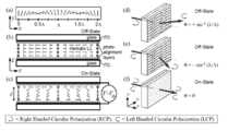
- 3Ais an explanatory diagram illustrating the function of the first polarization diffraction grating
- FIG. 3Bis an explanatory diagram illustrating the function of the second polarization diffraction grating.
- FIG. 3Cis an explanatory view for explaining the configuration of the first polarization diffraction grating and the second polarization diffraction grating
- FIG. 3Dis an explanation for explaining the function of the liquid crystal polarization rotation element.
- the first polarization diffraction grating 101ais a flat polarization diffraction grating (see FIG. 3A). Further, one surface is an incident surface, and the other surface opposite to the one surface is an output surface, and ⁇ is set to any angle of 3 ° to 60 °, preferably 5 ° to 60 °. When circular circularly polarized light that is inclined at either + ⁇ or ⁇ with respect to the thickness direction is incident from the incident surface, the circularly polarized light can be diffracted in the thickness direction and emitted from the output surface. It is said.
- the thickness direction of the first polarization diffraction grating 101awhen clockwise circular polarized light is incident perpendicularly to the incident surface, the thickness direction of the first polarization diffraction grating 101a (the x direction in FIG. 3A).
- + 1st-order counterclockwise circularly polarized light inclined at an angle of + ⁇can be emitted from the emission surface (see the upper side of FIG. 3A).
- counterclockwise circularly polarized lightis incident perpendicularly to the incident surface, it is at an angle of ⁇ with respect to the thickness direction of the first polarization diffraction grating 101a (x direction in FIG. 3A).
- the inclined first-order clockwise circularly polarized lightcan be emitted from the emission surface (see the lower side of FIG. 3A). That is, the first polarization diffraction grating 101a emits only circularly polarized light that is diffracted in the ⁇ 1st order direction according to the rotational state of the incident circularly polarized light and whose rotational direction is opposite to the rotational direction before incidence. . This situation is the same even if the relationship between incidence and emission is reversed.
- the arrow attached to the first polarization diffraction grating 101aindicates the direction of the periodic direction vector of the first polarization diffraction grating 101a.
- the second polarization diffraction grating 101bis a flat polarization diffraction grating (see FIG. 3B).
- one surfaceis an incident surface
- the other surface facing the one surfaceis an exit surface
- the liquid crystal polarization rotator 103is arranged to face the first polarization.
- the circularly polarized light incident on the incident surface in a direction parallel to the thickness direction of the diffraction grating 101ais at an angle of either + ⁇ or ⁇ from the direction parallel to the thickness direction, depending on the rotation direction.
- the lightcan be diffracted in an inclined direction and can be emitted from the emission surface.
- the second polarization diffraction grating 101ba counterclockwise circle tilted at an angle of ⁇ with respect to the incident surface with respect to the thickness direction of the second polarization diffraction grating 101b (the x direction in FIG. 3B).
- the circularly polarized lightis diffracted in the thickness direction as clockwise circularly polarized light and can be emitted from the exit surface (see the upper side of FIG. 3B).
- the clockwise circularly polarized light inclined at an angle of + ⁇ with respect to the thickness direction of the second polarization diffraction grating 101b(the x direction in FIG.
- the circle The polarized lightis diffracted in the thickness direction as counterclockwise circularly polarized light and can be emitted from the emission surface (see the lower side in FIG. 3B). That is, the second polarization diffraction grating 101b emits only circularly polarized light that is diffracted in the ⁇ 1st order direction according to the rotational state of the incident circularly polarized light and whose rotational direction is opposite to the rotational direction before incidence. . This situation is the same even if the relationship between incidence and emission is reversed.
- the second polarization diffraction grating 101b and the first polarization diffraction grating 101ahave the same configuration and function except that the direction of the periodic direction vector is different.
- the arrow attached to the second polarization diffraction grating 101bindicates the direction of the periodic direction vector of the second polarization diffraction grating 101b.
- the configuration of the first polarization diffraction grating 101a and the second polarization diffraction grating 101bis shown in FIG.
- the long-chain molecules 102a and 102bare converted into the first polarization diffraction grating 101a and the second polarization diffraction diffraction.
- ⁇ in one directiony direction in FIG. 3C
- x direction in FIG. 3Cx direction in FIG. 3C
- the periodic structure of the long chain molecules 102a and 102bis arranged at regular intervals in another direction (z direction in FIG. 3C) perpendicular to the one direction in the plane. It is arranged side by side.
- the first polarization diffraction grating 101a and the second polarization diffraction grating 101bare configured such that the diffraction angle ⁇ satisfies the following formula (1), where the wavelength of light is ⁇ , similarly to a normal diffraction grating.
- the first polarization diffraction grating 101a and the second polarization diffraction grating 101bare not particularly limited as long as they have such characteristics, and can be appropriately selected according to the purpose.
- Special Table 2008- A polarizing diffraction grating having a high diffraction angle described in Japanese Patent No. 532085can be used.
- the liquid crystal polarization rotator 103is composed of a flat liquid crystal polarization rotator.
- one surfaceis an incident surface
- the other surface facing the one surfaceis an exit surface
- the first polarization diffraction grating 101a (and the second polarization diffraction grating 101b)is disposed.
- the circularly polarized light incident on the incident surface in the direction parallel to the thickness direction of the first polarization diffraction grating 101a(the x direction in FIG. 3D) is emitted from the first polarization diffraction grating 101a.
- the lightcan be emitted from the surface in a direction parallel to the thickness direction.
- the liquid crystal polarization rotator 103maintains the rotation direction of the circularly polarized light incident on the incident surface in the off state where a voltage is applied, and the circularly polarized light from the exit surface has the thickness.
- the lightcan be emitted in a direction parallel to the direction (x direction in FIG. 3D) (see the upper left and lower left in FIG. 3D).
- the rotation directionis reversed with respect to the circularly polarized light incident on the incident surface, and the circularly polarized light is parallel to the thickness direction from the output surface (FIG. 3).
- the lightcan be emitted in the x direction of (d) (see the upper right and lower right in FIG. 3D).
- the liquid crystal polarization rotation element 103is not particularly limited as long as it has such characteristics, and can be appropriately selected according to the purpose.
- the liquid crystal moleculesare homogeneously oriented in the xy plane and oriented in the y direction.
- a known liquid crystal polarization rotatorsuch as a liquid crystal phase modulator configured to be inclined in the x direction in the xy plane by applying a voltage can be used.
- a known liquid crystal polarization rotator of the typethat turns on when a voltage is applied and turns off when no voltage is applied can be used.
- the state in which the rotation direction of the circularly polarized light is reversedis referred to as an on state
- the state in which the rotation direction of the circularly polarized light is maintainedis described as an off state.
- the circularly polarized light input / output device of the present inventionit is possible to construct a small, multi-input, multi-output optical switch by using the circularly polarized rotational diffraction switch described above. That is, in the circular polarization rotation diffraction switch, the first polarization diffraction grating 101a and the second polarization diffraction grating 101b can have a large diffraction angle ⁇ of 3 ° to 60 °. In the output device, a small and multi-input multi-output optical switch can be configured using this feature.
- the circularly polarized light input / output deviceconstituting the multi-input multiple-output optical switch
- (1)a circularly polarized light input / output device in which two circularly polarized light irradiation units are arranged for one circularly polarized light rotation diffraction switch
- 2)It can be roughly classified into a circularly polarized light input / output device in which one circularly polarized light irradiation unit is arranged for one circularly polarized light rotational diffraction switch.
- the circularly polarized light input / output device according to the first embodimentis given as an example of (1)
- the circularly polarized light input / output devices according to the second and third embodimentsare given as examples of (2). Examples of embodiments according to the circularly polarized light input / output device of the present invention will be described.
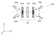
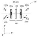
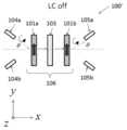
- FIG. 4is an explanatory diagram illustrating the configuration of the circularly polarized light input / output device 100 according to the first embodiment.
- the circularly polarized light input / output device 100includes a circularly polarized light rotation diffraction switch 106 having a first polarization diffraction grating 101a, a liquid crystal polarization rotation element 103, and a second polarization diffraction grating 101b, and a first circle.
- the polarized light irradiation unit 104a, the second circularly polarized light irradiation unit 104b, the first circularly polarized light receiving unit 105a, and the second circularly polarized light receiving unit 105bare configured to form an optical switch with two inputs and two outputs.
- the first circularly polarized light irradiation unit 104ahas + ⁇ with respect to the direction parallel to the thickness direction of the first polarization diffraction grating 101a (the x direction in FIG. 4) with respect to the incident surface of the first polarization diffraction grating 101a. Beam-shaped circularly polarized light can be irradiated from a direction inclined at an angle. Further, the second circularly polarized light irradiation unit 104b is in a direction parallel to the thickness direction of the first polarization diffraction grating 101a (the x direction in FIG. 4) with respect to the incident surface of the first polarization diffraction grating 101a. The circularly polarized light can be irradiated from a direction inclined at an angle of ⁇ .
- the first circularly polarized light irradiation unit 104a and the second circularly polarized light irradiation unit 104bare not particularly limited as long as they irradiate the circularly polarized light, and can be appropriately selected according to the purpose.
- a circularly polarized light irradiation deviceincluding a polarizing plate and the like can be used.
- the first circularly polarized light receiving unit 105ais inclined at an angle of + ⁇ from the second polarization diffraction grating 101b to a direction parallel to the thickness direction of the first polarization diffraction grating 101a (the x direction in FIG. 4).
- the circularly polarized light emitted in the directionis arranged in the emission direction, and the circularly polarized light can be received.
- the second circularly polarized light receiving unit 105bis emitted from the second polarizing diffraction grating 101b in a direction inclined at an angle of ⁇ with respect to a direction parallel to the thickness direction (x direction in FIG. 4).
- the circularly polarized lightis arranged in the emitting direction of the circularly polarized light and can receive the circularly polarized light.
- the 1st circular polarization light-receiving part 105a and the 2nd circular polarization light-receiving part 105bthere is no restriction
- a known light output device that outputs externallycan be used.
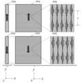
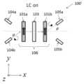
- FIGS. 5A to 5Dare explanatory views (1) to (4) for explaining the operation of the circularly polarized light input / output device 100 according to the first embodiment.
- a direction parallel to the thickness direction of the first polarization diffraction grating 101a from the first circularly polarized light irradiation unit 104a(in FIG. 5A).
- the left-handed circularly polarized lightis irradiated to the incident surface of the first polarization diffracted photon 101a in a direction inclined at an angle of + ⁇ with respect to the x-direction of the left-handed circularly polarized light
- the left-handed circularly polarized lightis The light is converted into clockwise circularly polarized light and diffracted in the thickness direction of the first polarization diffraction grating 101 a (x direction in FIG.
- the clockwise circularly polarized lightpasses through the liquid crystal polarization rotator 103 as it is and is introduced into the second polarization diffraction grating 101b.
- the clockwise circularly polarized light introduced into the second polarizing diffraction grating 101bis converted into the counterclockwise circularly polarized light by the second polarizing diffraction grating 101b and parallel to the thickness direction of the first polarizing diffraction grating 101a.
- the lightis diffracted at an angle of ⁇ with respect to the direction (x direction in FIG. 5A) and introduced into the second circularly polarized light receiving unit 105b.
- the clockwise circularly polarized light introduced into the liquid crystal polarization rotator 103is counterclockwise by the liquid crystal polarization rotator 103 as shown in FIG.
- the direction of rotationis converted into circularly polarized light and introduced into the second polarization diffraction grating 101b.
- the counterclockwise circularly polarized light introduced into the second polarization diffraction grating 101bis converted into the clockwise circular polarization by the second polarization diffraction grating 101b and parallel to the thickness direction of the first polarization diffraction grating 101a.
- the lightis diffracted at an angle of + ⁇ with respect to the direction (x direction in FIG. 5B) and introduced into the first circularly polarized light receiving unit 105a.
- the lightis converted into counterclockwise circularly polarized light by the diffraction grating 101 a and diffracted in the thickness direction of the first polarization diffraction grating 101 a (x direction in FIG. 5C) and introduced into the liquid crystal polarization rotation element 103.
- the liquid crystal polarization rotator 103is in the OFF state, the counterclockwise circularly polarized light is transmitted through the liquid crystal polarization rotator 103 as it is and is introduced into the second polarization diffraction grating 101b.
- the counterclockwise circularly polarized light introduced into the second polarization diffraction grating 101bis converted into the clockwise circular polarization by the second polarization diffraction grating 101b and parallel to the thickness direction of the first polarization diffraction grating 101a.
- the lightis diffracted at an angle of + ⁇ with respect to the direction (x direction in FIG. 5C) and introduced into the first circularly polarized light receiving unit 105a.
- the counterclockwise circularly polarized light introduced into the liquid crystal polarization rotator 103is rotated clockwise by the liquid crystal polarization rotator 103 as shown in FIG.
- the direction of rotationis converted into circularly polarized light and introduced into the second polarization diffraction grating 101b.
- the clockwise circularly polarized light introduced into the second polarizing diffraction grating 101bis converted into the counterclockwise circularly polarized light by the second polarizing diffraction grating 101b and parallel to the thickness direction of the first polarizing diffraction grating 101a.
- the lightis diffracted at an angle of ⁇ with respect to the direction (x direction in FIG. 5D) and introduced into the second circularly polarized light receiving unit 105b.
- the circularly polarized light input from the first circularly polarized light irradiation unit 104 a to the circularly polarized light rotation diffraction switch 106is changed based on the on / off operation of the liquid crystal polarization rotation element 103.
- the direction of the periodic direction vector of the first polarization diffraction grating 101a and the direction of the periodic direction vector of the second polarization diffraction grating 101bare set in opposite directions (see FIG. 4 and FIGS. 5 (a) to 5 (d)), even if the direction of these periodic direction vectors is set to the same direction, it can be configured as a 2-input 2-output optical switch.
- the operation of the circularly polarized light input / output device 100 ′which is a modification in which the direction of the periodic direction vector is set to the same direction, will be described with reference to FIGS. 5 (e) to 5 (h).
- 5E to 5Hare explanatory views (1) to (4) for explaining the operation of the modification of the circularly polarized light input / output device according to the first embodiment.
- a direction parallel to the thickness direction of the first polarization diffraction grating 101a from the first circularly polarized light irradiation unit 104a(FIG. 5E).
- the left-handed circularly polarized lightis irradiated to the incident surface of the first polarization diffracted photon 101a in a direction inclined at an angle of + ⁇ with respect to the x direction in the middle, the left-handed circularly polarized light is converted into the first polarization diffraction grating 101a.
- the clockwise circularly polarized light introduced into the second polarizing diffraction grating 101bis converted into the counterclockwise circularly polarized light by the second polarizing diffraction grating 101b and parallel to the thickness direction of the first polarizing diffraction grating 101a.
- the lightis diffracted at an angle of + ⁇ with respect to the direction (x direction in FIG. 5 (e)) and introduced into the first circularly polarized light receiving unit 105a.
- the clockwise circularly polarized light introduced into the liquid crystal polarization rotator 103is counterclockwise by the liquid crystal polarization rotator 103 as shown in FIG.
- the direction of rotationis converted into circularly polarized light and introduced into the second polarization diffraction grating 101b.
- the counterclockwise circularly polarized light introduced into the second polarization diffraction grating 101bis converted into the clockwise circular polarization by the second polarization diffraction grating 101b and parallel to the thickness direction of the first polarization diffraction grating 101a.
- the lightis diffracted at an angle of ⁇ with respect to the direction (x direction in FIG. 5 (f)) and introduced into the second circularly polarized light receiving unit 105 b.
- the clockwise circularly polarized lightWhen the clockwise circularly polarized light is applied to the incident surface of the first polarization diffracted photon 101a in a direction inclined at an angle of ⁇ with respect to the x direction in (g), the clockwise circularly polarized light is The light is converted into counterclockwise circularly polarized light by the polarization diffraction grating 101 a and is diffracted in the thickness direction of the first polarization diffraction grating 101 a (x direction in FIG. 5G) and introduced into the liquid crystal polarization rotation element 103.
- the counterclockwise circularly polarized lightis transmitted through the liquid crystal polarization rotator 103 as it is and is introduced into the second polarization diffraction grating 101b.
- the counterclockwise circularly polarized light introduced into the second polarization diffraction grating 101bis converted into the clockwise circular polarization by the second polarization diffraction grating 101b and parallel to the thickness direction of the first polarization diffraction grating 101a.
- the lightis diffracted at an angle of ⁇ with respect to the direction (x direction in FIG. 5G) and introduced into the second circularly polarized light receiving unit 105b.
- the counterclockwise circularly polarized light introduced into the liquid crystal polarization rotator 103is rotated clockwise by the liquid crystal polarization rotator 103 as shown in FIG.
- the direction of rotationis converted into circularly polarized light and introduced into the second polarization diffraction grating 101b.
- the clockwise circularly polarized light introduced into the second polarizing diffraction grating 101bis converted into the counterclockwise circularly polarized light by the second polarizing diffraction grating 101b and parallel to the thickness direction of the first polarizing diffraction grating 101a.
- the lightis diffracted at an angle of + ⁇ with respect to the direction (x direction in FIG. 5 (h)) and introduced into the first circularly polarized light receiving unit 105a.
- the circular polarization input / output device 100 ′in which the direction of the periodic direction vector of the first polarization diffraction grating 101a and the direction of the periodic direction vector of the second polarization diffraction grating 101b are set in the same direction, Similar to the circularly polarized light input / output device 100 in which the directions of these periodic direction vectors are set in opposite directions, it can be configured as a two-input two-output optical switch.
- the liquid crystalbetween the first polarization diffraction grating 101a and the liquid crystal polarization rotator 103, and the liquid crystal
- the descriptionhas been made with the polarization rotating element 103 and the second polarization diffraction grating 101b spaced apart from each other and facing each other, as shown in FIG.
- FIG. 6is an explanatory diagram illustrating a configuration example of a circularly polarized light rotation diffraction switch.
- the circularly polarized light input / output device 100(and the circularly polarized light input / output device 100 ′ which is a modified example thereof) according to the first embodiment, as the simplest example of the aspect of (1), two inputs and two outputs are provided.
- the two circular polarization rotation diffraction switchesare arranged in the two output directions of the one circular polarization rotation diffraction switch to configure a multi-input and multi-output optical switch. can do.
- descriptionwill be given as an example of the configuration of such a multi-input multi-output optical switch.
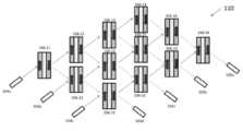
- a circularly polarized light input / output device 110(Second Embodiment) A circularly polarized light input / output device 110 according to a second embodiment will be described with reference to FIG.
- the circularly polarized light input / output device 110+ ⁇ with respect to the direction parallel to the thickness direction of the first polarization diffraction grating from the second polarization diffraction grating of the circular polarization rotation diffraction switch 106-11 in the first row and the first column.
- the numbers 34 to 34correspond to the numbers in the matrix), but the entrance surface of each of the first polarization diffraction gratings and the exit surface of the second polarization diffraction gratings are parallel to each other in a 3 ⁇ 4 matrix lattice. Arranged above.
- an angle of ⁇ with respect to the direction parallel to the thickness direction with respect to the incident surface of each of the first polarization diffraction gratings of the three circularly polarized light diffraction switches 106-11 to 106-31 in the first rowThe three circularly polarized light irradiating units 104a to 104c that can irradiate the circularly polarized light from the direction tilted at 4 are arranged, and each of the four circularly polarized light rotational diffraction switches 106-31 to 106-34 in the third row is arranged.
- Polarized light receiving units(105a to 105d) are arranged.
- each of the circularly polarized light rotational diffraction switches 106-11 to 106-34operates in the same manner as the circularly polarized light rotational diffraction switch 106 in the circularly polarized light input / output device 100, and has three inputs.
- a 4-output optical switchcan be configured.
- the circularly polarized light input / output device 110an optical switch having 3 inputs and 4 outputs is configured.
- the circularly polarized light input / output device of the present inventionhas M rows and N columns, where M and N are integers of 2 or more. By applying to a matrix lattice, an optical switch with any M input and N output can be configured.
- the circularly polarized light input / output device 110changes the direction of the periodic vectors of the circularly polarized light rotational diffraction switches 106-11 to 106-34 as appropriate so that the circularly polarized light irradiation units 104a to 104c are parallel to the thickness direction.
- the circularly polarized lightis irradiated from a direction inclined at an angle of + ⁇ with respect to the direction, and the circularly polarized light receiving portions 105a to 105d are irradiated from the direction inclined at an angle of + ⁇ with respect to a direction parallel to the thickness direction.
- the arrangement of each elementmay be changed by receiving polarized light.
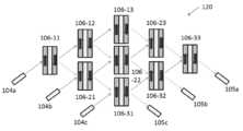
- a circularly polarized light input / output device 120according to a third embodiment will be described with reference to FIG. Unlike the circularly polarized light input / output device 110, the circularly polarized light input / output device 120 has the same number of rows and columns. That is, in the circularly polarized light input / output device 120, the second polarization diffraction grating of the circular polarization rotation diffraction switch 106-11 in the first row and the first column extends from the second polarization diffraction grating to a direction parallel to the thickness direction of the first polarization diffraction grating.
- each of the first polarization diffraction grating and the exit surface of the second polarization diffraction gratingare parallel to each other in 3 rows and 3 columns. Arranged on a rhombus lattice.
- an angle of ⁇ with respect to the direction parallel to the thickness direction with respect to the incident surface of each of the first polarization diffraction gratings of the three circularly polarized light diffraction switches 106-11 to 106-31 in the first rowThe three circularly polarized light irradiating units 104a to 104c that can irradiate the circularly polarized light from the direction tilted at the right and left are arranged, and the three circularly polarized light rotational diffraction switches 106-31 to 106-33 in the third row are arranged.
- Polarized light receiving portions 105a to 105care arranged.
- each of the circularly polarized light rotational diffraction switches 106-11 to 106-33operates in the same manner as the circularly polarized light rotational diffraction switch 106 in the circularly polarized light input / output device 100, and has three inputs.
- a three-output optical switchcan be configured.
- the one-to-one optical connection between the circularly polarized light irradiating units 104a to 104c and the circularly polarized light receiving units 105a to 105cis 3!
- the number of the circularly polarized light rotational diffraction switches usedis smaller than that of the circularly polarized light input / output device 110, and a more compact and effective optical connection can be set.
- the circularly polarized light input / output device 120an optical switch having 3 inputs and 3 outputs is configured.
- the circularly polarized light input / output device of the present inventionhas an L row and L column rhombus lattice in which L is an integer of 2 or more.
- an optical switch with any L input and L outputcan be configured.
- the circularly polarized light input / output device 120changes the direction of the periodic vectors of the circularly polarized light rotational diffraction switches 106-11 to 106-33 as appropriate so that the circularly polarized light irradiation units 104a to 104c are parallel to the thickness direction.
- the circularly polarized lightis irradiated from a direction inclined at an angle of + ⁇ with respect to the direction, and the circularly polarized light receiving portions 105a to 105c are irradiated from the direction inclined at an angle of + ⁇ with respect to a direction parallel to the thickness direction.
- the arrangement of each elementmay be changed by receiving polarized light.
- FIG. 9is explanatory drawing explaining the structure of the circularly polarized light input / output apparatus which concerns on the modification of 2nd, 3rd embodiment.
- a plurality of the circular polarization rotation diffraction switches adjacent to each other in the in-plane direction of the incident surface of the first polarization diffraction grating and the output surface of the second polarization diffraction gratingare configured to have an integrated circular polarization rotation diffraction switch 107-1 to 107-5 configured to share as one integrally formed member.
- each of the integrated circular polarization rotation diffraction switches 107-1, 107-3, and 107-5includes five of the first polarization diffraction grating and the second polarization diffraction grating that are integrally formed. Depending on the divided liquid crystal polarization rotation element, it functions as the five circular polarization rotation diffraction switches. Further, each of the integrated circular polarization rotation diffraction switches 107-2 and 107-4 is formed by dividing the liquid crystal into four parts, although the first polarization diffraction grating and the second polarization diffraction grating are integrally formed. Depending on the polarization rotation element, it functions as the four circular polarization rotation diffraction switches.
- the integrated circularly polarized light rotational diffraction switches 107-1 to 107-5are respectively in the planes of the entrance surface of the first polarization diffraction grating and the exit surface of the second polarization diffraction grating. Since the plurality of circularly polarized light rotary diffraction switches adjacent to each other in the direction are integrally integrated without any interval, the circularly polarized light rotary diffraction switches 107-1 to 107-5 in the integrated circularly polarized light rotary diffraction switches 107-1 to 107-5 are integrated. By optimizing the number, a smaller optical switch can be configured.
- the circularly polarized light irradiating units 104b and 104care integrated with the circularly polarized light rotational diffraction switches 107-1 to 107 with respect to the circularly polarized light rotational diffraction switches involved in the 3-input 3-output optical switch.
- an integrated circularly polarized light rotating diffraction switchIn contrast to the circularly polarized light rotating diffraction switch in which circularly polarized light is indirectly irradiated via -2, and the circularly polarized light receiving portions 105b and 105c are involved in the 3-input 3-output optical switch, an integrated circularly polarized light rotating diffraction switch Although the circularly polarized light is indirectly received through 107-4 to 107-5, the circularly polarized light receiving part and the circularly polarized light receiving part of this aspect are also used as one aspect of the present invention. It is included in the idea of a polarization input / output device.
- circularly polarized light emitted from the second polarization diffraction grating in a direction inclined at either + ⁇ or ⁇ with respect to a direction parallel to the thickness direction of the first polarization diffraction gratingIt has a circularly polarized light receiving part 105a (105b, 105c) arranged in the emission direction and capable of receiving the circularly polarized light, and the circularly polarized light receiving part 105a (105b) from the position where the circularly polarized light receiving part 105a (105b, 105c) is arranged.
- the circularly polarized light irradiation unit 104a(104b, 104c) is irradiated with the same circularly polarized light as the circularly polarized light irradiated from the circularly polarized light irradiation unit 104a (104b, 104c) in the opposite direction to the light receiving direction of the circularly polarized light.
- the circularly polarized light rotation diffraction switchis disposed at a position where a confocal point is formed with the circularly polarized light irradiated from the circularly polarized light.
- the spot radius of the light beam in the circularly polarized light irradiated from the circularly polarized light irradiation unit 104a (104b, 104c) and the circularly polarized light irradiated from the arrangement position of the circularly polarized light receiving unit 105a (105b, 105c)is ⁇ 2 ⁇ 0
- the spot radius of the light beam at the confocal pointis narrowed to about ⁇ o .
- fwhich is the Rayleigh range can be expressed as the following formula (2).
- ⁇ in the equation (2)represents an operating wavelength
- the wavefront of the light beam with a spot diameter of 2 ⁇ 2 ⁇ o irradiated from the circularly polarized light irradiation unit 104a (104b, 104c)becomes flat as it approaches the confocal position. Thereafter, the wavefront of the flattened light beam becomes a circular arc as it approaches the position where the circularly polarized light receiving portions 105a (105b, 105c) are arranged due to diffraction by the circularly polarized light diffraction switch, and again has a spot diameter of 2 ⁇ 2 ⁇ o. It becomes a light beam.
- the circularly polarized light rotation diffraction switchat the confocal position of the confocal lens system, the diffraction loss is reduced and a low loss switch operation is possible.
- two integrated left and right circular polarization switchesare arranged so that the central integrated circular polarization rotation diffraction switch is arranged at the confocal position among the five integrated circular polarization rotation diffraction switches.
- a rotary diffraction switch, a circularly polarized light irradiation unit 104a (104b, 104c), and a circularly polarized light receiving unit 105a (105b, 105c)are arranged.
- a substantially center position of a region where the plurality of circularly polarized light rotation diffraction switches are arrangedbe the confocal position.
- the angle ⁇is more than 0 ° and not more than 45 °, and preferably 1 ° to 15 °. Further, the angle ⁇ + ⁇ is less than 90 °.
- This aspecthas an advantage that stray light such as reflected light is difficult to enter.
- 11 and 12are explanatory views (1) and (2) showing a state in which input / output is performed in directions inclined by angles ⁇ + ⁇ and ⁇ . Note that the items described in the above-described embodiments can be applied to other items.
- Circularly polarized light input / output device101a First polarization diffraction grating 101b Second polarization diffraction grating 102a, 102b Long chain molecule 103 Liquid crystal polarization rotation element 104a-c Circularly polarized light irradiation unit 105a- d Circularly polarized light receiving unit 106, 106-11 to 106-34 Circularly polarized light rotational diffraction switch 107-1 to 107-5 Integrated circularly polarized light rotational diffraction switch
Landscapes
- Physics & Mathematics (AREA)
- Nonlinear Science (AREA)
- General Physics & Mathematics (AREA)
- Optics & Photonics (AREA)
- Chemical & Material Sciences (AREA)
- Crystallography & Structural Chemistry (AREA)
- Liquid Crystal (AREA)
- Polarising Elements (AREA)
- Optical Modulation, Optical Deflection, Nonlinear Optics, Optical Demodulation, Optical Logic Elements (AREA)
- Diffracting Gratings Or Hologram Optical Elements (AREA)
Abstract
Description
Translated fromJapanese本発明は、円偏光の回転方向及び回折方向を制御可能とし、光スイッチとして利用可能な円偏光入出力装置に関する。The present invention relates to a circularly polarized light input / output device that can control the rotation direction and diffraction direction of circularly polarized light and can be used as an optical switch.
従来の技術では、Micro Electro Mechanical Systems(MEMS)ミラーアレイやLiquid Crystal on Si(LCoS)液晶変調器をスイッチングエンジンとして光スイッチが構成されてきた。
しかし、これらのスイッチングエンジンでは、低損失に光を偏向できる角度が高々2°程度であることから、光ビームのスイッチングを行う場合、長大な光路長を確保する必要があり、光スイッチを小型化することが困難である。In the prior art, an optical switch has been configured using a Micro Electro Mechanical Systems (MEMS) mirror array or a Liquid Crystal on Si (LCoS) liquid crystal modulator as a switching engine.
However, in these switching engines, the angle at which light can be deflected with low loss is at most about 2 °. Therefore, when switching light beams, it is necessary to ensure a long optical path length and downsize the optical switch. Difficult to do.
こうしたことから、液晶変調器と、主に+1次と-1次の回折光が生じる偏光回折格子とで構成される光ビーム偏向器が提案されている(非特許文献1、図1参照)。
しかしながら、この提案では、図1に示すように1×N型(N≧2)の光スイッチに適用できるものの、2入力2出力の光スイッチや複数の入力ポートから複数の出力ポートへ光路の切替えを行う多入力多出力の光スイッチを構成することができない。なお、図1は、従来の光ビーム偏光器における偏光の入出力状況を説明する説明図である。For this reason, a light beam deflector composed of a liquid crystal modulator and a polarization diffraction grating that mainly generates + 1st order and −1st order diffracted light has been proposed (see Non-Patent
However, although this proposal can be applied to a 1 × N type (N ≧ 2) optical switch as shown in FIG. 1, the optical path is switched from a 2-input 2-output optical switch or a plurality of input ports to a plurality of output ports. It is not possible to construct a multi-input multi-output optical switch. FIG. 1 is an explanatory diagram for explaining the input / output state of polarized light in a conventional light beam polarizer.
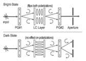
また、第1の偏光回折格子と液晶偏光回転素子と第2の偏光回折格子とで構成される偏光無依存の変調器が提案されている(非特許文献2、図2参照)。
しかしながら、この提案においても、図2に示すように1入力2出力の光スイッチに適用できるものの、前記2入力2出力の光スイッチや前記多入力多出力の光スイッチを構成することができない配置とされる。なお、図2は、従来の変調器における偏光の入出力状況を説明する説明図である。Further, a polarization-independent modulator composed of a first polarization diffraction grating, a liquid crystal polarization rotation element, and a second polarization diffraction grating has been proposed (see Non-Patent Document 2 and FIG. 2).
However, this proposal can be applied to a 1-input 2-output optical switch as shown in FIG. 2, but the 2-input 2-output optical switch and the multi-input multi-output optical switch cannot be configured. Is done. FIG. 2 is an explanatory diagram for explaining an input / output state of polarized light in a conventional modulator.
これらの提案で用いられる偏光回折格子は、格子周期を短くすることによって回折角を5°以上とすることが可能であり、この利点を生かした小型で多入力多出力の光スイッチを構成可能な円偏光入出力装置の開発が求められる。The polarization diffraction gratings used in these proposals can have a diffraction angle of 5 ° or more by shortening the grating period, and a compact, multi-input, multi-output optical switch can be constructed taking advantage of this advantage. Development of circularly polarized light input / output device is required.
本発明は、従来技術における前記諸問題を解決し、小型で多入力多出力の光スイッチを構成可能な円偏光入出力装置を提供することを課題とする。It is an object of the present invention to provide a circularly polarized light input / output device that can solve the above-mentioned problems in the prior art and can constitute a compact, multi-input, multi-output optical switch.
前記課題を解決するための手段としては、以下の通りである。即ち、
<1> 一の面が入射面とされ、前記一の面と対向する他の面が出射面とされ、θを3°~60°のいずれかの角度として、厚さ方向に対し+θ及び-θのいずれかの角度で傾斜するビーム状の円偏光が前記入射面から入射されたときに前記円偏光を前記厚さ方向に回折させて出射面から出射可能とされる平板状の第1の偏光回折格子と、一の面が入射面とされ、前記一の面と対向する他の面が出射面とされるとともに前記第1の偏光回折格子と対向して配され、前記第1の偏光回折格子から前記厚さ方向と平行な方向で前記入射面に入射される前記円偏光に対し、電圧印加に伴うオンオフ制御により、前記円偏光の回転方向を反転させた状態及び前記回転方向を維持させた状態のいずれかの状態とし、この状態の前記円偏光を前記出射面から前記厚さ方向と平行な方向に出射可能とされる平板状の液晶偏光回転素子と、一の面が入射面とされ、前記一の面と対向する他の面が出射面とされるとともに前記液晶偏光回転素子と対向して配され、前記液晶偏光回転素子から前記厚さ方向と平行な方向で前記入射面に入射される前記円偏光を、前記回転方向に応じて、前記厚さ方向と平行な方向から+θ及び-θのいずれかの角度で傾斜する方向に回折させて前記出射面から出射可能とされる平板状の第2の偏光回折格子と、を有する円偏光回転回折スイッチと、前記第1の偏光回折格子の前記入射面に対し、前記厚さ方向と平行な方向に対し+θ及び-θのいずれかの角度で傾斜する方向から前記円偏光を照射可能とされる円偏光照射部と、を備えることを特徴とする円偏光入出力装置。
<2> 円偏光回転回折スイッチが、第1の偏光回折格子と液晶偏光回転素子と第2の偏光回折格子とをこの順で積層させて構成される前記<1>に記載の円偏光入出力装置。
<3> 第1の偏光回折格子の入射面に対し、前記第1の偏光回折格子の厚さ方向と平行な方向に対し+θの角度で傾斜する方向から円偏光を照射可能とされる円偏光照射部を第1の円偏光照射部としたとき、更に、前記第1の偏光回折格子の入射面に対し、前記第1の偏光回折格子の厚さ方向と平行な方向に対し-θの角度で傾斜する方向から前記円偏光を照射可能とされる第2の円偏光照射部を有する前記<1>から<2>のいずれかに記載の円偏光入出力装置。
<4> 更に、第2の偏光回折格子から第1の偏光回折格子の厚さ方向と平行な方向に対して+θの角度で傾斜する方向に出射される円偏光の出射方向に配され、前記円偏光を受光可能とされる第1の円偏光受光部と、前記厚さ方向と平行な方向に対して-θの角度で傾斜する方向に出射される前記円偏光の出射方向に配され、前記円偏光を受光可能とされる第2の円偏光受光部と、を備える前記<3>に記載の円偏光入出力装置。
<5> 1行1列目の円偏光回転回折スイッチの第2の偏光回折格子から第1の偏光回折格子の厚さ方向と平行な方向に対して+θの角度で傾斜する方向に出射される円偏光の出射方向を行の方向とし、前記1行1列目の円偏光回転回折スイッチの前記第2の偏光回折格子から前記厚さ方向と平行な方向に対して-θの角度で傾斜する方向に出射される前記円偏光の出射方向を列の方向として、M及びNを2以上の整数として、M×N個の円偏光回転回折スイッチが、それぞれの前記第1の偏光回折格子の入射面及び前記第2の偏光回折格子の出射面を平行な状態としてM行N列のマトリクス格子上に配され、1列目におけるM個の前記円偏光回転回折スイッチの前記各第1の偏光回折格子の入射面に対し、前記厚さ方向と平行な方向に対して+θ及び-θのいずれかの角度で傾斜する方向から前記円偏光を照射可能とされるM個の円偏光照射部が配され、M行目におけるN個の前記円偏光回転回折スイッチの前記各第2の偏光回折格子から前記厚さ方向と平行な方向に対して+θ及び-θのいずれかの角度で傾斜する方向に出射される前記円偏光の出射方向に前記円偏光を受光可能とされるN個の円偏光受光部が配される前記<1>から<2>のいずれかに記載の円偏光入出力装置。
<6> 1行1列目の円偏光回転回折スイッチの第2の偏光回折格子から第1の偏光回折格子の厚さ方向と平行な方向に対して+θの角度で傾斜する方向に出射される円偏光の出射方向を行の方向とし、前記1行1列目の円偏光回転回折スイッチの前記第2の偏光回折格子から前記厚さ方向と平行な方向に対して-θの角度で傾斜する方向に出射される前記円偏光の出射方向を列の方向として、Lを2以上の整数として2L個の円偏光回転回折スイッチが、それぞれの前記第1の偏光回折格子の入射面及び前記第2の偏光回折格子の出射面を平行な状態としてL行L列の菱形格子上に配され、1列目におけるL個の前記円偏光回転回折スイッチの前記各第1の偏光回折格子の入射面に対し、前記厚さ方向と平行な方向に対して+θ及び-θのいずれかの角度で傾斜する方向から前記円偏光を照射可能とされるL個の円偏光照射部が配され、L行目におけるL個の前記円偏光回転回折スイッチの前記各第2の偏光回折格子から前記厚さ方向と平行な方向に対して+θ及び-θのいずれかの角度で傾斜する方向に出射される前記円偏光の出射方向に前記円偏光を受光可能とされるL個の円偏光受光部が配される前記<5>に記載の円偏光入出力装置。
<7> 第1の偏光回折格子の入射面及び第2の偏光回折格子の出射面の面内方向に隣接する複数の円偏光回転回折スイッチが、それぞれの前記第1の偏光回折格子及び前記第2の偏光回折格子を、一体形成された1つの部材として共有するように構成される前記<5>から<6>のいずれかに記載の円偏光入出力装置。
<8> 第2の偏光回折格子から第1の偏光回折格子の厚さ方向と平行な方向に対して+θ及び-θのいずれかの角度で傾斜する方向に出射される円偏光の出射方向に配され、前記円偏光を受光可能とされる円偏光受光部を有し、前記円偏光受光部の配置位置から前記円偏光受光部における前記円偏光の受光方向と反対方向に円偏光照射部から照射される円偏光と同一の円偏光を照射したとき、前記円偏光照射部から照射される前記円偏光とで共焦点が形成される位置に、円偏光回転回折スイッチが配される前記<1>から<2>のいずれかに記載の円偏光入出力装置。
<9> 一の面が入射面とされ、前記一の面と対向する他の面が出射面とされ、角度θを3°~60°のいずれかの角度とし、角度αを0°を超え45°以下のいずれかの角度とし、かつ、α+θを90°未満として、厚さ方向に対し+(θ+α)及び-(θ-α)のいずれかの角度で傾斜するビーム状の円偏光が前記入射面から入射されたときに前記円偏光を前記厚さ方向に対し、前記角度αで傾斜する傾斜方向に回折させて出射面から出射可能とされる平板状の第1の偏光回折格子と、一の面が入射面とされ、前記一の面と対向する他の面が出射面とされるとともに前記第1の偏光回折格子と対向して配され、前記第1の偏光回折格子から前記傾斜方向で前記入射面に入射される前記円偏光に対し、電圧印加に伴うオンオフ制御により、前記円偏光の回転方向を反転させた状態及び前記回転方向を維持させた状態のいずれかの状態とし、この状態の前記円偏光を前記出射面から前記傾斜方向に出射可能とされる平板状の液晶偏光回転素子と、一の面が入射面とされ、前記一の面と対向する他の面が出射面とされるとともに前記液晶偏光回転素子と対向して配され、前記液晶偏光回転素子から前記傾斜方向で前記入射面に入射される前記円偏光を、前記回転方向に応じて、前記厚さ方向と平行な方向に対し+(θ+α)及び-(θ-α)のいずれかの角度で傾斜する方向に回折させて前記出射面から出射可能とされる平板状の第2の偏光回折格子と、を有する円偏光回転回折スイッチと、前記第1の偏光回折格子の前記入射面に対し、前記厚さ方向と平行な方向に対し+(θ+α)及び-(θ-α)のいずれかの角度で傾斜する方向から前記円偏光を照射可能とされる円偏光照射部と、を備えることを特徴とする円偏光入出力装置。Means for solving the problems are as follows. That is,
<1> One surface is an entrance surface, the other surface opposite to the one surface is an exit surface, and θ is any angle from 3 ° to 60 °, and + θ and − A flat plate-shaped first beam that is diffracted in the thickness direction and can be emitted from the emission surface when beam-like circularly polarized light that is inclined at any angle of θ is incident from the incident surface. The polarization grating and one surface is the entrance surface, the other surface facing the one surface is the exit surface, and the first polarization diffraction grating is disposed facing the first polarization grating. With respect to the circularly polarized light incident on the incident surface in a direction parallel to the thickness direction from the diffraction grating, the rotational direction of the circularly polarized light is reversed and the rotational direction is maintained by on / off control accompanying voltage application. The circularly polarized light in this state is moved forward from the exit surface. A flat plate-shaped liquid crystal polarization rotation element capable of emitting light in a direction parallel to the thickness direction, one surface is an incident surface, and the other surface opposite to the one surface is an output surface, and the liquid crystal The circularly polarized light that is arranged opposite to the polarization rotation element and is incident on the incident surface in a direction parallel to the thickness direction from the liquid crystal polarization rotation element is parallel to the thickness direction according to the rotation direction. A circular polarization rotation diffraction switch having a flat plate-like second polarization diffraction grating that is diffracted from any direction into a direction inclined at any angle of + θ and −θ and can be emitted from the emission surface; A circularly polarized light irradiation unit capable of irradiating the circularly polarized light from a direction inclined at any angle of + θ and −θ with respect to a direction parallel to the thickness direction with respect to the incident surface of the first polarization diffraction grating And a circularly polarized light input / output device.
<2> The circularly polarized light input / output according to <1>, wherein the circularly polarized light rotation diffraction switch is configured by laminating a first polarization diffraction grating, a liquid crystal polarization rotation element, and a second polarization diffraction grating in this order. apparatus.
<3> Circularly polarized light that can be irradiated with circularly polarized light from a direction inclined at an angle of + θ with respect to a direction parallel to the thickness direction of the first polarized light diffraction grating with respect to the incident surface of the first polarized light diffraction grating When the irradiation unit is the first circularly polarized light irradiation unit, an angle of −θ with respect to the direction parallel to the thickness direction of the first polarization diffraction grating with respect to the incident surface of the first polarization diffraction grating is further provided. The circularly polarized light input / output device according to any one of <1> to <2>, further including a second circularly polarized light irradiating unit configured to be able to irradiate the circularly polarized light from a direction inclined at a point.
<4> Further, the second polarization diffraction grating is arranged in the emission direction of circularly polarized light emitted in a direction inclined at an angle of + θ with respect to a direction parallel to the thickness direction of the first polarization diffraction grating, A first circularly polarized light receiving part capable of receiving circularly polarized light, and an emission direction of the circularly polarized light emitted in a direction inclined at an angle of −θ with respect to a direction parallel to the thickness direction, The circularly polarized light input / output device according to <3>, further comprising: a second circularly polarized light receiving unit capable of receiving the circularly polarized light.
<5> The light is emitted from the second polarization diffraction grating of the circular polarization rotation diffraction switch in the first row and first column in a direction inclined at an angle of + θ with respect to a direction parallel to the thickness direction of the first polarization diffraction grating. The direction of emission of circularly polarized light is the row direction, and the second polarization diffraction grating of the circularly polarized light rotational diffraction switch in the first row and first column is inclined at an angle of −θ with respect to a direction parallel to the thickness direction. M × N circular polarization rotation diffraction switches are incident on the respective first polarization diffraction gratings, where the emission direction of the circularly polarized light emitted in the direction is a column direction, M and N are integers of 2 or more. The first polarization diffraction of the M circular polarization rotation diffraction switches in the first column is arranged on the matrix grating of M rows and N columns with the plane and the exit surface of the second polarization diffraction grating in parallel. + With respect to the direction parallel to the thickness direction with respect to the incident surface of the grating M circularly polarized light irradiators that can irradiate the circularly polarized light from a direction inclined at any angle of θ and −θ are arranged, and each of the N circularly polarized light rotational diffraction switches in the Mth row is arranged. The circularly polarized light can be received in the emitting direction of the circularly polarized light emitted from the second polarization diffraction grating in a direction inclined at either + θ or −θ with respect to a direction parallel to the thickness direction. The circularly polarized light input / output device according to any one of <1> to <2>, wherein N circularly polarized light receiving units are arranged.
<6> The light is emitted from the second polarization diffraction grating of the circular polarization rotation diffraction switch in the first row and first column in a direction inclined at an angle of + θ with respect to a direction parallel to the thickness direction of the first polarization diffraction grating. The direction of emission of circularly polarized light is the row direction, and the second polarization diffraction grating of the circularly polarized light rotational diffraction switch in the first row and first column is inclined at an angle of −θ with respect to a direction parallel to the thickness direction. 2L circular polarization rotation diffraction switches, where the emission direction of the circularly polarized light emitted in the direction is a column direction and L is an integer of 2 or more, the incident surface of the first polarization diffraction grating and the second Are arranged on L rows and L columns of rhombic gratings with the exit surfaces of the polarization diffraction gratings of the first and second polarization diffraction gratings in the first column being incident on the incident surfaces of the first polarization diffraction gratings. On the other hand, any of + θ and -θ with respect to the direction parallel to the thickness direction. L circularly polarized light irradiating portions that can irradiate the circularly polarized light from a direction inclined at the angle are arranged, and the second polarization diffraction gratings of the L circularly polarized light rotational diffraction switches in the Lth row L circularly polarized lights capable of receiving the circularly polarized light in the emission direction of the circularly polarized light emitted in a direction inclined at any angle of + θ and −θ with respect to a direction parallel to the thickness direction The circularly polarized light input / output device according to <5>, wherein the light receiving unit is arranged.
<7> A plurality of circular polarization rotation diffraction switches adjacent in the in-plane direction of the entrance surface of the first polarization diffraction grating and the exit surface of the second polarization diffraction grating include the first polarization diffraction grating and the first polarization diffraction grating, respectively. The circularly polarized light input / output device according to any one of <5> to <6>, configured to share the two polarization diffraction gratings as one integrally formed member.
<8> In the emission direction of circularly polarized light emitted from the second polarization diffraction grating in a direction inclined at either + θ or −θ with respect to a direction parallel to the thickness direction of the first polarization diffraction grating. A circularly polarized light receiving unit arranged to be capable of receiving the circularly polarized light, and from the circularly polarized light receiving unit in a direction opposite to the circularly polarized light receiving direction from the arrangement position of the circularly polarized light receiving unit. When the same circularly polarized light as the irradiated circularly polarized light is irradiated, the circularly polarized light rotation diffraction switch is disposed at a position where a confocal point is formed with the circularly polarized light irradiated from the circularly polarized light irradiation unit. The circularly polarized light input / output device according to any one of <2> to <2>.
<9> One surface is the entrance surface, the other surface facing the one surface is the exit surface, the angle θ is any angle between 3 ° and 60 °, and the angle α exceeds 0 ° The beam-shaped circularly polarized light is inclined at any angle of + (θ + α) and − (θ−α) with respect to the thickness direction with any angle of 45 ° or less and α + θ less than 90 °. A first polarizing diffraction grating in the form of a plate that can be emitted from the exit surface by diffracting the circularly polarized light in the tilt direction inclined at the angle α with respect to the thickness direction when entering from the entrance surface; One surface is an entrance surface, the other surface facing the one surface is an exit surface, and is disposed facing the first polarization diffraction grating, and is inclined from the first polarization diffraction grating. For the circularly polarized light incident on the incident surface in the direction, the circularly polarized light is controlled by on / off control accompanying voltage application. A plate-like liquid crystal polarization rotator that is in a state in which the rotation direction is reversed or in a state in which the rotation direction is maintained, and the circularly polarized light in this state can be emitted from the emission surface in the tilt direction. One surface is the entrance surface, the other surface facing the one surface is the exit surface, and the liquid crystal polarization rotator is disposed opposite the liquid crystal polarization rotator in the tilt direction. The circularly polarized light incident on the incident surface is tilted at an angle of either + (θ + α) or − (θ−α) with respect to a direction parallel to the thickness direction according to the rotation direction. A circular polarization rotating diffraction switch having a flat plate-like second polarization diffraction grating that can be diffracted and emitted from the exit surface, and the thickness direction with respect to the entrance surface of the first polarization diffraction grating + (Θ + α) and-(θ-α) Circularly polarized light output device, characterized in that it comprises, a circularly polarized light irradiating unit that is capable of irradiating the circularly polarized light from a direction inclined by any angle.
本発明によれば、従来技術における前記諸問題を解決することができ、小型で多入力多出力の光スイッチを構成可能な円偏光入出力装置を提供することができる。According to the present invention, it is possible to solve the above-mentioned problems in the prior art, and to provide a circularly polarized light input / output device that can constitute a small-sized, multi-input multi-output optical switch.
(円偏光回転回折スイッチ)
本発明の円偏光入出力装置に用いられる円偏光回転回折スイッチについて、図3(a)~(d)を参照しつつ説明をする。前記円偏光回転回折スイッチは、第1の偏光回折格子と、液晶偏光回転素子と、第2の偏光回折格子とを有する。
なお、図3(a)は、前記第1の偏光回折格子の機能を説明する説明図であり、図3(b)は、前記第2の偏光回折格子の機能を説明する説明図であり、図3(c)は、前記第1の偏光回折格子及び前記第2の偏光回折格子の構成を説明する説明図であり、図3(d)は、前記液晶偏光回転素子の機能を説明する説明図である。(Circularly polarized rotation diffraction switch)
A circularly polarized light rotational diffraction switch used in the circularly polarized light input / output device of the present invention will be described with reference to FIGS. 3 (a) to 3 (d). The circular polarization rotation diffraction switch includes a first polarization diffraction grating, a liquid crystal polarization rotation element, and a second polarization diffraction grating.
3A is an explanatory diagram illustrating the function of the first polarization diffraction grating, and FIG. 3B is an explanatory diagram illustrating the function of the second polarization diffraction grating. FIG. 3C is an explanatory view for explaining the configuration of the first polarization diffraction grating and the second polarization diffraction grating, and FIG. 3D is an explanation for explaining the function of the liquid crystal polarization rotation element. FIG.
第1の偏光回折格子101aは、平板状の偏光回折格子で構成される(図3(a)参照)。また、一の面が入射面とされ、前記一の面と対向する他の面が出射面とされ、θを°3°~60°、好適には5°~60°のいずれかの角度として、厚さ方向に対し+θ及び-θのいずれかの角度で傾斜するビーム状の円偏光が前記入射面から入射されたときに前記円偏光を前記厚さ方向に回折させて出射面から出射可能とされる。The first
第1の偏光回折格子101aでは、前記入射面に対して垂直に右回り円偏光を入射させると、第1の偏光回折格子101aの厚さ方向(図3(a)中のx方向)に対して、+θの角度で傾斜する+1次の左回り円偏光を前記出射面から出射可能とされる(図3(a)の上側参照)。
また、前記入射面に対して垂直に左回り円偏光を入射させると、第1の偏光回折格子101aの厚さ方向(図3(a)中のx方向)に対して、-θの角度で傾斜する-1次の右回り円偏光を前記出射面から出射可能とされる(図3(a)の下側参照)。
即ち、第1の偏光回折格子101aでは、入射される円偏光の回転状態に応じて、±1次の方向に回折され、回転方向が入射前の回転方向と反対となる円偏光のみを出射する。
この状況は、入射及び出射の関係を反対としても同様である。
なお、図3(a)中、第1の偏光回折格子101aに付した矢印は、第1の偏光回折格子101aの周期方向ベクトルの向きを示している。In the first
Further, when counterclockwise circularly polarized light is incident perpendicularly to the incident surface, it is at an angle of −θ with respect to the thickness direction of the first
That is, the first
This situation is the same even if the relationship between incidence and emission is reversed.
In FIG. 3A, the arrow attached to the first
第2の偏光回折格子101bは、平板状の偏光回折格子で構成される(図3(b)参照)。また、一の面が入射面とされ、前記一の面と対向する他の面が出射面とされるとともに液晶偏光回転素子103と対向して配され、液晶偏光回転素子103から第1の偏光回折格子101aの厚さ方向と平行な方向で前記入射面に入射される前記円偏光を、前記回転方向に応じて、前記厚さ方向と平行な方向から+θ及び-θのいずれかの角度で傾斜する方向に回折させて前記出射面から出射可能とされる。The second
第2の偏光回折格子101bでは、前記入射面に対して、第2の偏光回折格子101bの厚さ方向(図3(b)中のx方向)に対し-θの角度で傾斜する左回り円偏光を入射させると、前記円偏光を右回り円偏光として前記厚さ方向に回折させて出射面から出射可能とされる(図3(b)の上側参照)。
また、前記入射面に対して、第2の偏光回折格子101bの厚さ方向(図3(b)中のx方向)に対し+θの角度で傾斜する右回り円偏光を入射させると、前記円偏光を左回り円偏光として前記厚さ方向に回折させて出射面から出射可能とされる(図3(b)の下側参照)。
即ち、第2の偏光回折格子101bでは、入射される円偏光の回転状態に応じて、±1次の方向に回折され、回転方向が入射前の回転方向と反対となる円偏光のみを出射する。
この状況は、入射及び出射の関係を反対としても同様である。
つまり、第2の偏光回折格子101bと、第1の偏光回折格子101aとは、周期方向ベクトルの向きが異なるのみで同様の構成及び機能を有する。
なお、図3(b)中、第2の偏光回折格子101bに付した矢印は、第2の偏光回折格子101bの周期方向ベクトルの向きを示している。In the second
Moreover, when the clockwise circularly polarized light inclined at an angle of + θ with respect to the thickness direction of the second
That is, the second
This situation is the same even if the relationship between incidence and emission is reversed.
That is, the second
In FIG. 3B, the arrow attached to the second
第1の偏光回折格子101a及び第2の偏光回折格子101bの構成を図3(c)に示す。
図3(c)に示すように、第1の偏光回折格子101a及び第2の偏光回折格子101bでは、長鎖状の分子102a及び102bが、第1の偏光回折格子101a及び第2の偏光回折格子101bの厚さ方向(図3(c)中のx方向)に対し面内で直交する一の方向(図3(c)中のy方向)に周期Λで周期的に回転して配向されて配されるとともに、これら長鎖状の分子102a及び102bの周期的な構造が、面内で前記一の方向と直交する他の方向(図3(c)中のz方向)に一定間隔で並設されて構成される。
また、第1の偏光回折格子101a及び第2の偏光回折格子101bでは、回折角θが、通常の回折格子と同じく、光の波長をλとして次式(1)を満たすように構成される。The configuration of the first
As shown in FIG. 3C, in the first
In addition, the first

第1の偏光回折格子101a及び第2の偏光回折格子101bとしては、このような特徴を有するものであれば特に制限はなく、目的に応じて適宜選択することができ、例えば、特表2008-532085号公報等に記載される高回折角の偏光回折格子を用いることができる。The first
図3(d)に示すように、液晶偏光回転素子103は、平板状の液晶偏光回転素子で構成される。また、一の面が入射面とされ、前記一の面と対向する他の面が出射面とされるとともに第1の偏光回折格子101a(及び第2の偏光回折格子101b)と対向して配され、第1の偏光回折格子101aから第1の偏光回折格子101aの厚さ方向と平行な方向(図3(d)中のx方向)で前記入射面に入射される前記円偏光を前記出射面から前記厚さ方向と平行な方向に出射可能とされる。As shown in FIG. 3D, the liquid
ここで、液晶偏光回転素子103では、電圧を加えたオフ状態において、前記入射面に入射される前記円偏光に対し、前記回転方向を維持させて、前記円偏光を前記出射面から前記厚さ方向と平行な方向(図3(d)のx方向)に出射可能とされる(図3(d)の左上及び左下参照)。
また、電圧を加えないオン状態で、前記入射面に入射される前記円偏光に対し、前記回転方向を反転させて、前記円偏光を前記出射面から前記厚さ方向と平行な方向(図3(d)のx方向)に出射可能とされる(図3(d)の右上及び右下参照)。Here, the liquid
Further, in the ON state where no voltage is applied, the rotation direction is reversed with respect to the circularly polarized light incident on the incident surface, and the circularly polarized light is parallel to the thickness direction from the output surface (FIG. 3). The light can be emitted in the x direction of (d) (see the upper right and lower right in FIG. 3D).
液晶偏光回転素子103としては、このような特徴を有するものであれば特に制限はなく、目的に応じて適宜選択することができ、例えば、xy平面内でy方向を向いたホモジニアス配向した液晶分子が電圧印可によって、xy平面内でx方向に傾く構成の液晶位相変調器等の公知の液晶偏光回転素子を用いることができる。なお、液晶の配向によっては、液晶偏光回転素子103に代えて、電圧を加えるとオン状態になり、電圧を加えないとオフ状態になるタイプの公知の液晶偏光回転素子も利用することができる。以降では、前記円偏光の回転方向を反転させる状態をオン状態とし、前記円偏光の回転方向を維持させる状態をオフ状態として説明する。The liquid crystal
本発明の円偏光入出力装置では、以上に説明した円偏光回転回折スイッチを用いて、小型で多入力多出力の光スイッチを構成可能とする。即ち、前記円偏光回転回折スイッチでは、第1の偏光回折格子101a及び第2の偏光回折格子101bの回折角θを3°~60°として、大きくとることができるため、本発明の円偏光入出力装置では、この特徴を利用して小型で多入力多出力の光スイッチを構成可能とする。In the circularly polarized light input / output device of the present invention, it is possible to construct a small, multi-input, multi-output optical switch by using the circularly polarized rotational diffraction switch described above. That is, in the circular polarization rotation diffraction switch, the first
前記多入力多出力の光スイッチを構成する円偏光入出力装置としては、(1)1つの円偏光回転回折スイッチに対して2つの円偏光照射部が配される円偏光入出力装置と、(2)1つの円偏光回転回折スイッチに対して1つの円偏光照射部が配される円偏光入出力装置とに大別することができる。
以下では、前記(1)の一例として第1の実施形態に係る円偏光入出力装置を挙げ、また、前記(2)の例として第2、第3の実施形態に係る各円偏光入出力装置を挙げて、本発明の前記円偏光入出力装置に係る実施形態の例を説明する。As the circularly polarized light input / output device constituting the multi-input multiple-output optical switch, (1) a circularly polarized light input / output device in which two circularly polarized light irradiation units are arranged for one circularly polarized light rotation diffraction switch; 2) It can be roughly classified into a circularly polarized light input / output device in which one circularly polarized light irradiation unit is arranged for one circularly polarized light rotational diffraction switch.
In the following, the circularly polarized light input / output device according to the first embodiment is given as an example of (1), and the circularly polarized light input / output devices according to the second and third embodiments are given as examples of (2). Examples of embodiments according to the circularly polarized light input / output device of the present invention will be described.
(第1の実施形態)
第1の実施形態に係る円偏光入出力装置100を図4を参照しつつ説明する。なお、図4は、第1の実施形態に係る円偏光入出力装置100の構成を説明する説明図である。
円偏光入出力装置100は、図4に示すように、第1の偏光回折格子101a、液晶偏光回転素子103及び第2の偏光回折格子101bを有する円偏光回転回折スイッチ106と、第1の円偏光照射部104aと、第2の円偏光照射部104bと、第1の円偏光受光部105aと、第2の円偏光受光部105bとを備え、2入力2出力の光スイッチを構成する。(First embodiment)
The circularly polarized light input /
As shown in FIG. 4, the circularly polarized light input /
第1の円偏光照射部104aは、第1の偏光回折格子101aの入射面に対し、第1の偏光回折格子101aの厚さ方向と平行な方向(図4中のx方向)に対し+θの角度で傾斜する方向からビーム状の円偏光を照射可能とされる。
また、第2の円偏光照射部104bは、第1の偏光回折格子101aの入射面に対し、第1の偏光回折格子101aの厚さ方向と平行な方向(図4中のx方向)に対し-θの角度で傾斜する方向から前記円偏光を照射可能とされる。The first circularly polarized
Further, the second circularly polarized
第1の円偏光照射部104a及び第2の円偏光照射部104bとしては、前記円偏光を照射するものであれば特に制限はなく、目的に応じて適宜選択することができ、公知のレーザ光源及び偏光板等で構成される円偏光照射装置を用いることができる。The first circularly polarized
第1の円偏光受光部105aは、第2の偏光回折格子101bから第1の偏光回折格子101aの厚さ方向と平行な方向(図4中のx方向)に対して+θの角度で傾斜する方向に出射される円偏光の出射方向に配され、前記円偏光を受光可能とされる。
また、第2の円偏光受光部105bは、第2の偏光回折格子101bから前記厚さ方向と平行な方向(図4中のx方向)に対して-θの角度で傾斜する方向に出射される前記円偏光の出射方向に配され、前記円偏光を受光可能とされる。The first circularly polarized
The second circularly polarized
第1の円偏光受光部105a及び第2の円偏光受光部105bとしては、特に制限はなく、目的に応じて適宜選択することができ、例えば、受光した前記円偏光を目的とする状態の光として外部出力する公知の光出力装置を用いることができる。There is no restriction | limiting in particular as the 1st circular polarization light-receiving
第1の実施形態に係る円偏光入出力装置100の動作について、図5(a)~(d)を参照しつつ説明をする。なお、図5(a)~(d)は、第1の実施形態に係る円偏光入出力装置100の動作を説明する説明図(1)~(4)である。The operation of the circularly polarized light input /
図5(a)に示すように、円偏光入出力装置100では、第1の円偏光照射部104aから、第1の偏光回折格子101aの厚さ方向と平行な方向(図5(a)中のx方向)に対し+θの角度で傾斜する方向で、第1の偏光回折光子101aの入射面に対して左回り円偏光を照射すると、前記左回り円偏光が第1の偏光回折格子101aにより右回り円偏光に変換されるとともに第1の偏光回折格子101aの厚さ方向(図5(a)中のx方向)に回折され、液晶偏光回転素子103に導入される。
このとき、液晶偏光回転素子103が前記オフ状態であると、前記右回り円偏光は、液晶偏光回転素子103をそのまま透過して、第2の偏光回折格子101bに導入される。
第2の偏光回折格子101bに導入された前記右回り円偏光は、第2の偏光回折格子101bにより前記左回り円偏光に変換されるとともに第1の偏光回折格子101aの厚さ方向と平行な方向(図5(a)中のx方向)に対して-θの角度をもって回折され、第2の円偏光受光部105bに導入される。As shown in FIG. 5A, in the circularly polarized light input /
At this time, if the liquid
The clockwise circularly polarized light introduced into the second
一方、液晶偏光回転素子103が前記オン状態であると、図5(b)に示すように、液晶偏光回転素子103に導入される前記右回り円偏光は、液晶偏光回転素子103により前記左回り円偏光に回転方向が変換され、第2の偏光回折格子101bに導入される。
第2の偏光回折格子101bに導入された前記左回り円偏光は、第2の偏光回折格子101bにより前記右回り円偏光に変換されるとともに第1の偏光回折格子101aの厚さ方向と平行な方向(図5(b)中のx方向)に対して+θの角度をもって回折され、第1の円偏光受光部105aに導入される。On the other hand, when the liquid
The counterclockwise circularly polarized light introduced into the second
次に、図5(c)に示すように、円偏光入出力装置100では、第2の円偏光照射部104bから、第1の偏光回折格子101aの厚さ方向と平行な方向(図5(c)中のx方向)に対し-θの角度で傾斜する方向で、第1の偏光回折光子101aの入射面に対して右回り円偏光を照射すると、前記右回り円偏光が第1の偏光回折格子101aにより左回り円偏光に変換されるとともに第1の偏光回折格子101aの厚さ方向(図5(c)中のx方向)に回折され、液晶偏光回転素子103に導入される。
このとき、液晶偏光回転素子103が前記オフ状態であると、前記左回り円偏光は、液晶偏光回転素子103をそのまま透過して、第2の偏光回折格子101bに導入される。
第2の偏光回折格子101bに導入された前記左回り円偏光は、第2の偏光回折格子101bにより前記右回り円偏光に変換されるとともに第1の偏光回折格子101aの厚さ方向と平行な方向(図5(c)中のx方向)に対して+θの角度をもって回折され、第1の円偏光受光部105aに導入される。Next, as shown in FIG. 5C, in the circularly polarized light input /
At this time, if the liquid
The counterclockwise circularly polarized light introduced into the second
一方、液晶偏光回転素子103が前記オン状態であると、図5(d)に示すように、液晶偏光回転素子103に導入される前記左回り円偏光は、液晶偏光回転素子103により前記右回り円偏光に回転方向が変換され、第2の偏光回折格子101bに導入される。
第2の偏光回折格子101bに導入された前記右回り円偏光は、第2の偏光回折格子101bにより前記左回り円偏光に変換されるとともに第1の偏光回折格子101aの厚さ方向と平行な方向(図5(d)中のx方向)に対して-θの角度をもって回折され、第2の円偏光受光部105bに導入される。On the other hand, when the liquid
The clockwise circularly polarized light introduced into the second
以上のように、円偏光入出力装置100では、第1の円偏光照射部104aから円偏光回転回折スイッチ106に入力される円偏光を、液晶偏光回転素子103のオンオフ動作に基づき、第1の円偏光受光部105a及び第2の円偏光受光部105bの2つの出力先を選択して出力させるとともに、第2の円偏光照射部104bから円偏光回転回折スイッチ106に入力される円偏光を、液晶偏光回転素子103のオンオフ動作に基づき、第1の円偏光受光部105a及び第2の円偏光受光部105bの2つの出力先を選択して出力させることができ、第1の円偏光照射部104a及び第2の円偏光照射部104bの2つの入力を切替えて利用する2入力2出力の光スイッチとして構成することができる。As described above, in the circularly polarized light input /
なお、円偏光入出力装置100では、第1の偏光回折格子101aの周期方向ベクトルの向きと、第2の偏光回折格子101bの周期方向ベクトルの向きとを反対方向に設定しているが(図4、図5(a)~(d)参照)、これらの周期方向ベクトルの向きを同一方向に設定しても、2入力2出力の光スイッチとして構成することができる。
周期方向ベクトルの向きを同一方向に設定した変形例である円偏光入出力装置100’の動作について、図5(e)~(h)を参照しつつ説明する。なお、図5(e)~(h)は、第1の実施形態に係る円偏光入出力装置の変形例の動作を説明する説明図(1)~(4)である。In the circular polarization input /
The operation of the circularly polarized light input /
図5(e)に示すように、円偏光入出力装置100’では、第1の円偏光照射部104aから、第1の偏光回折格子101aの厚さ方向と平行な方向(図5(e)中のx方向)に対し+θの角度で傾斜する方向で、第1の偏光回折光子101aの入射面に対して左回り円偏光を照射すると、前記左回り円偏光が第1の偏光回折格子101aにより右回り円偏光に変換されるとともに第1の偏光回折格子101aの厚さ方向(図5(e)中のx方向)に回折され、液晶偏光回転素子103に導入される。
このとき、液晶偏光回転素子103が前記オフ状態であると、前記右回り円偏光は、液晶偏光回転素子103をそのまま透過して、第2の偏光回折格子101bに導入される。
第2の偏光回折格子101bに導入された前記右回り円偏光は、第2の偏光回折格子101bにより前記左回り円偏光に変換されるとともに第1の偏光回折格子101aの厚さ方向と平行な方向(図5(e)中のx方向)に対して+θの角度をもって回折され、第1の円偏光受光部105aに導入される。As shown in FIG. 5E, in the circularly polarized light input /
At this time, if the liquid
The clockwise circularly polarized light introduced into the second
一方、液晶偏光回転素子103が前記オン状態であると、図5(f)に示すように、液晶偏光回転素子103に導入される前記右回り円偏光は、液晶偏光回転素子103により前記左回り円偏光に回転方向が変換され、第2の偏光回折格子101bに導入される。
第2の偏光回折格子101bに導入された前記左回り円偏光は、第2の偏光回折格子101bにより前記右回り円偏光に変換されるとともに第1の偏光回折格子101aの厚さ方向と平行な方向(図5(f)中のx方向)に対して-θの角度をもって回折され、第2の円偏光受光部105bに導入される。On the other hand, when the liquid
The counterclockwise circularly polarized light introduced into the second
次に、図5(g)に示すように、円偏光入出力装置100’では、第2の円偏光照射部104bから、第1の偏光回折格子101aの厚さ方向と平行な方向(図5(g)中のx方向)に対し-θの角度で傾斜する方向で、第1の偏光回折光子101aの入射面に対して右回り円偏光を照射すると、前記右回り円偏光が第1の偏光回折格子101aにより左回り円偏光に変換されるとともに第1の偏光回折格子101aの厚さ方向(図5(g)中のx方向)に回折され、液晶偏光回転素子103に導入される。
このとき、液晶偏光回転素子103が前記オフ状態であると、前記左回り円偏光は、液晶偏光回転素子103をそのまま透過して、第2の偏光回折格子101bに導入される。
第2の偏光回折格子101bに導入された前記左回り円偏光は、第2の偏光回折格子101bにより前記右回り円偏光に変換されるとともに第1の偏光回折格子101aの厚さ方向と平行な方向(図5(g)中のx方向)に対して-θの角度をもって回折され、第2の円偏光受光部105bに導入される。Next, as shown in FIG. 5G, in the circularly polarized light input /
At this time, if the liquid
The counterclockwise circularly polarized light introduced into the second
一方、液晶偏光回転素子103が前記オン状態であると、図5(h)に示すように、液晶偏光回転素子103に導入される前記左回り円偏光は、液晶偏光回転素子103により前記右回り円偏光に回転方向が変換され、第2の偏光回折格子101bに導入される。
第2の偏光回折格子101bに導入された前記右回り円偏光は、第2の偏光回折格子101bにより前記左回り円偏光に変換されるとともに第1の偏光回折格子101aの厚さ方向と平行な方向(図5(h)中のx方向)に対して+θの角度をもって回折され、第1の円偏光受光部105aに導入される。On the other hand, when the liquid
The clockwise circularly polarized light introduced into the second
以上のように、第1の偏光回折格子101aの周期方向ベクトルの向きと、第2の偏光回折格子101bの周期方向ベクトルの向きとを同一方向に設定した円偏光入出力装置100’においても、これら周期方向ベクトルの向きが反対方向に設定された円偏光入出力装置100と同様に、2入力2出力の光スイッチとして構成することができる。As described above, also in the circular polarization input /
また、第1の実施形態に係る円偏光入出力装置100(及びその変形例である円偏光入出力装置100’)では、第1の偏光回折格子101a-液晶偏光回転素子103間、及び、液晶偏光回転素子103-第2の偏光回折格子101b間に間隔を空けて、これらを対向させた状態で説明をしたが、これらは、図6に示すように、第1の偏光回折格子101a、液晶偏光回転素子103及び第2の偏光回折格子101bの順で積層されて、一体の円偏光回転回折スイッチ106を構成してもよい。このような構成とすることで、より小型の光スイッチを構成することができる。なお、図6は、円偏光回転回折スイッチの構成例を説明する説明図である。In the circularly polarized light input /
また、第1の実施形態に係る円偏光入出力装置100(及びその変形例である円偏光入出力装置100’)では、前記(1)の態様の最も簡素な例として、2入力2出力の光スイッチの構成例で説明を行ったが、2つの前記円偏光回転回折スイッチを1つの前記円偏光回転回折スイッチの2つの出力方向に配して、より多入力で多出力の光スイッチを構成することができる。
以下に説明する第2、第3の各実施形態においては、こうした多入力多出力の光スイッチの構成例として説明する。Further, in the circularly polarized light input / output device 100 (and the circularly polarized light input /
In each of the second and third embodiments described below, description will be given as an example of the configuration of such a multi-input multi-output optical switch.
(第2の実施形態)
第2の実施形態に係る円偏光入出力装置110を図7を参照しつつ説明する。
円偏光入出力装置110では、1行1列目の円偏光回転回折スイッチ106-11の前記第2の偏光回折格子から前記第1の偏光回折格子の厚さ方向と平行な方向に対して+θの角度で傾斜する方向に出射される前記円偏光の出射方向を行の方向とし、1行1列目の円偏光回転回折スイッチ106-11の前記第2の偏光回折格子から前記厚さ方向と平行な方向に対して-θの角度で傾斜する方向に出射される円偏光の出射方向を列の方向として、3×4=12個の円偏光回転回折スイッチ106-11~106-34(11~34の数字は、行列の数字に対応する)が、それぞれの前記第1の偏光回折格子の入射面及び前記第2の偏光回折格子の出射面を平行な状態として3行4列のマトリクス格子上に配される。
また、1列目における3個の円偏光回転回折スイッチ106-11~106-31の前記各第1の偏光回折格子の入射面に対し、前記厚さ方向と平行な方向に対し-θの角度で傾斜する方向から前記円偏光を照射可能とされる3個の円偏光照射部104a~104cが配され、3行目における4個の円偏光回転回折スイッチ106-31~106-34の前記各第2の偏光回折格子から前記厚さ方向と平行な方向に対して-θの角度で傾斜する方向に出射される前記円偏光の出射方向に前記円偏光を受光可能とされる4個の円偏光受光部(105a~105d)が配される。(Second Embodiment)
A circularly polarized light input /
In the circularly polarized light input /
In addition, an angle of −θ with respect to the direction parallel to the thickness direction with respect to the incident surface of each of the first polarization diffraction gratings of the three circularly polarized light diffraction switches 106-11 to 106-31 in the first row The three circularly polarized
このように構成される円偏光入出力装置110では、各円偏光回転回折スイッチ106-11~106-34が、円偏光入出力装置100における円偏光回転回折スイッチ106と同様に動作し、3入力4出力の光スイッチを構成することができる。In the circularly polarized light input /
なお、円偏光入出力装置110では、3入力4出力の光スイッチを構成することとしたが、本発明の円偏光入出力装置は、M及びNを2以上の整数としたM行N列のマトリクス格子に適用することで、任意のM入力N出力の光スイッチを構成することができる。
また、円偏光入出力装置110は、円偏光回転回折スイッチ106-11~106-34の周期ベクトルの向きを適宜変更することで、円偏光照射部104a~104cを、前記厚さ方向と平行な方向に対し+θの角度で傾斜する方向から前記円偏光を照射することとし、円偏光受光部105a~105dを、前記厚さ方向と平行な方向に対して+θの角度で傾斜する方向から前記円偏光を受光することとして、各要素の配置が変更されてもよい。In the circularly polarized light input /
In addition, the circularly polarized light input /
(第3の実施形態)
次に、第3の実施形態に係る円偏光入出力装置120を図8を参照しつつ説明する。
円偏光入出力装置120は、円偏光入出力装置110と異なり、行の数と列の数とが同数とされる。
即ち、円偏光入出力装置120では、1行1列目の円偏光回転回折スイッチ106-11の前記第2の偏光回折格子から前記第1の偏光回折格子の厚さ方向と平行な方向に対して+θの角度で傾斜する方向に出射される前記円偏光の出射方向を行の方向とし、1行1列目の円偏光回転回折スイッチ106-11の前記第2の偏光回折格子から前記厚さ方向と平行な方向に対して-θの角度で傾斜する方向に出射される円偏光の出射方向を列の方向として、3×3=9個の円偏光回転回折スイッチ106-11~106-33(11~33の数字は、行列の数字に対応する)が、それぞれの前記第1の偏光回折格子の入射面及び前記第2の偏光回折格子の出射面を平行な状態として3行3列の菱形格子上に配される。
また、1列目における3個の円偏光回転回折スイッチ106-11~106-31の前記各第1の偏光回折格子の入射面に対し、前記厚さ方向と平行な方向に対し-θの角度で傾斜する方向から前記円偏光を照射可能とされる3個の円偏光照射部104a~104cが配され、3行目における3個の円偏光回転回折スイッチ106-31~106-33の前記各第2の偏光回折格子から前記厚さ方向と平行な方向に対して-θの角度で傾斜する方向に出射される前記円偏光の出射方向に前記円偏光を受光可能とされる3個の円偏光受光部105a~105cが配される。(Third embodiment)
Next, a circularly polarized light input /
Unlike the circularly polarized light input /
That is, in the circularly polarized light input /
In addition, an angle of −θ with respect to the direction parallel to the thickness direction with respect to the incident surface of each of the first polarization diffraction gratings of the three circularly polarized light diffraction switches 106-11 to 106-31 in the first row The three circularly polarized
このように構成される円偏光入出力装置120では、各円偏光回転回折スイッチ106-11~106-33が、円偏光入出力装置100における円偏光回転回折スイッチ106と同様に動作し、3入力3出力の光スイッチを構成することができる。
また、円偏光入出力装置120では、円偏光照射部104a~104cと円偏光受光部105a~105cとの間で、1対1の光接続を3!通りに設定することが可能であり、円偏光入出力装置110よりも用いる前記円偏光回転回折スイッチの数が少なく、より小型で効果的な光接続の設定を行うことができる。In the circularly polarized light input /
In the circularly polarized light input /
なお、円偏光入出力装置120では、3入力3出力の光スイッチを構成することとしたが、本発明の円偏光入出力装置は、Lを2以上の整数としたL行L列の菱形格子に適用することで、任意のL入力L出力の光スイッチを構成することができる。
また、円偏光入出力装置120は、円偏光回転回折スイッチ106-11~106-33の周期ベクトルの向きを適宜変更することで、円偏光照射部104a~104cを、前記厚さ方向と平行な方向に対し+θの角度で傾斜する方向から前記円偏光を照射することとし、円偏光受光部105a~105cを、前記厚さ方向と平行な方向に対して+θの角度で傾斜する方向から前記円偏光を受光することとして、各要素の配置が変更されてもよい。In the circularly polarized light input /
In addition, the circularly polarized light input /
次に、第2,3の実施形態の変形例に係る円偏光入出力装置130について図9を参照しつつ説明する。なお、図9は、第2,3の実施形態の変形例に係る円偏光入出力装置の構成を説明する説明図である。
円偏光入出力装置130では、前記第1の偏光回折格子の入射面及び前記第2の偏光回折格子の出射面の面内方向に隣接する複数の前記円偏光回転回折スイッチが、それぞれの前記第1の偏光回折格子及び前記第2の偏光回折格子を、一体形成された1つの部材として共有するように構成された一体型円偏光回転回折スイッチ107-1~107-5を有して構成される。
ここで、一体型円偏光回転回折スイッチ107-1,107-3,107-5のそれぞれは、前記第1の偏光回折格子及び前記第2の偏光回折格子が一体形成されるものの、5つに分割された液晶偏光回転素子に応じて、5つの前記円偏光回転回折スイッチとして機能する。
また、一体型円偏光回転回折スイッチ107-2,107-4のそれぞれについても、前記第1の偏光回折格子及び前記第2の偏光回折格子が一体形成されるものの、4つに分割された液晶偏光回転素子に応じて、4つの前記円偏光回転回折スイッチとして機能する。Next, a circularly polarized light input /
In the circular polarization input /
Here, each of the integrated circular polarization rotation diffraction switches 107-1, 107-3, and 107-5 includes five of the first polarization diffraction grating and the second polarization diffraction grating that are integrally formed. Depending on the divided liquid crystal polarization rotation element, it functions as the five circular polarization rotation diffraction switches.
Further, each of the integrated circular polarization rotation diffraction switches 107-2 and 107-4 is formed by dividing the liquid crystal into four parts, although the first polarization diffraction grating and the second polarization diffraction grating are integrally formed. Depending on the polarization rotation element, it functions as the four circular polarization rotation diffraction switches.
この円偏光入出力装置130では、一体型円偏光回転回折スイッチ107-1~107-5が、それぞれ前記第1の偏光回折格子の入射面及び前記第2の偏光回折格子の出射面の面内方向に隣接する複数の前記円偏光回転回折スイッチを間隔を設けずに一体に集積させて構成されるため、一体型円偏光回転回折スイッチ107-1~107-5における前記円偏光回転回折スイッチの数を最適化することにより、より小型の光スイッチを構成することも可能となる。In this circularly polarized light input /
また、円偏光入出力装置130では、一体型円偏光回転回折スイッチ107-1,107-5の中央に存在する1つの前記円偏光回転回折スイッチ、一体型円偏光回転回折スイッチ107-2,107-4の中央に存在する2つの前記円偏光回転回折スイッチ、及び一体型円偏光回転回折スイッチ107-3の中央に存在する3つの前記円偏光回転回折スイッチにより、円偏光入出力装置120と同様に3入力3出力の光スイッチを構成することができる。
円偏光入出力装置130では、円偏光照射部104b,104cが、前記3入力3出力の光スイッチに関与する前記円偏光回転回折スイッチに対して、一体型円偏光回転回折スイッチ107-1乃至107-2を介して間接的に円偏光を照射し、円偏光受光部105b,105cが前記3入力3出力の光スイッチに関与する前記円偏光回転回折スイッチに対して、一体型円偏光回転回折スイッチ107-4乃至107-5を介して間接的に円偏光を受光する態様とされるが、このような態様についても前記円偏光照射部及び前記円偏光受光部の一態様として、本発明の円偏光入出力装置の思想に含まれる。Further, in the circularly polarized light input /
In the circularly polarized light input /
次に、前記円偏光回転回折スイッチ、前記円偏光照射部及び前記円偏光受光部の好適な位置関係について図10を参照しつつ説明する。なお、共焦点に円偏光回転回折スイッチを配する構成を示す説明図である。Next, a preferred positional relationship among the circularly polarized light rotation diffraction switch, the circularly polarized light irradiation unit, and the circularly polarized light receiving unit will be described with reference to FIG. In addition, it is explanatory drawing which shows the structure which arrange | positions a circularly polarized light rotation diffraction switch in a confocal.
この例では、前記第2の偏光回折格子から前記第1の偏光回折格子の厚さ方向と平行な方向に対して+θ及び-θのいずれかの角度で傾斜する方向に出射される円偏光の出射方向に配され、前記円偏光を受光可能とされる円偏光受光部105a(105b,105c)を有し、円偏光受光部105a(105b,105c)の配置位置から円偏光受光部105a(105b,105c)における前記円偏光の受光方向と反対方向に円偏光照射部104a(104b,104c)から照射される円偏光と同一の円偏光を照射したとき、円偏光照射部104a(104b,104c)から照射される前記円偏光とで共焦点が形成される位置に、前記円偏光回転回折スイッチが配される。In this example, circularly polarized light emitted from the second polarization diffraction grating in a direction inclined at either + θ or −θ with respect to a direction parallel to the thickness direction of the first polarization diffraction grating. It has a circularly polarized
円偏光照射部104a(104b,104c)から照射される前記円偏光と、円偏光受光部105a(105b,105c)の配置位置から照射される前記円偏光とにおける光ビームのスポット半径を√2ω0とすると、共焦点での前記光ビームのスポット半径は、ωo程度に狭小化する。
このとき、レイリー範囲であるfは、下記式(2)のように表すことができる。The spot radius of the light beam in the circularly polarized light irradiated from the circularly polarized
At this time, f which is the Rayleigh range can be expressed as the following formula (2).

円偏光照射部104a(104b,104c)から照射される、スポット直径2√2ωoの光ビームの波面は、共焦点位置に近づくにつれて平坦となる。その後、平坦化された前記光ビームの波面は、前記円偏光回転回折スイッチでの回折により、円偏光受光部105a(105b,105c)の配置位置に近づくにつれて円弧となり、再びスポット直径2√2ωoの光ビームとなる。
したがって、共焦点レンズ系の共焦点位置に前記円偏光回転回折スイッチを配置することで、回折損失が低減されて低損失なスイッチ動作が可能となる。
図10に示す例では、5つの前記一体型円偏光回転回折スイッチのうち、中央の一体型円偏光回転回折スイッチが共焦点位置に配されるように、左右2つずつの前記一体型円偏光回転回折スイッチ、円偏光照射部104a(104b,104c)及び円偏光受光部105a(105b,105c)が配されることが好ましい。つまり、前記円偏光回転回折スイッチが複数配される場合には、これら円偏光回転回折スイッチが複数配される領域の略中心位置が前記共焦点位置とされることが好ましい。The wavefront of the light beam with a spot diameter of 2√2ωo irradiated from the circularly polarized
Therefore, by disposing the circularly polarized light rotation diffraction switch at the confocal position of the confocal lens system, the diffraction loss is reduced and a low loss switch operation is possible.
In the example shown in FIG. 10, two integrated left and right circular polarization switches are arranged so that the central integrated circular polarization rotation diffraction switch is arranged at the confocal position among the five integrated circular polarization rotation diffraction switches. It is preferable that a rotary diffraction switch, a circularly polarized
以上に説明した諸実施形態では、偏光回折格子に対して、右回り円偏光及び左回り円偏光を、前記偏光回折格子の厚さ方向に対し、角度θで傾斜させた方向で入出力させる構成を示したが、図11及び図12に示すように角度θ+α,θ-αで傾斜させた方向で入出力させることも可能である。この態様では、円偏光回転回折スイッチを構成する諸部材中で、前記円偏光が前記偏光回折格子の厚さ方向に対し角度αで傾斜する方向で伝搬する。角度αとしては、0°を超え45°以下であり、好適には、1°~15°である。また、角度θ+αとしては、90°未満である。この態様とすると、反射光などの迷光が入りにくい利点がある。なお、図11及び図12は、角度θ+α、θ-αで傾斜させた方向で入出力させる状態を示す説明図(1)、(2)である。
なお、その他の事項については、前述の諸実施形態で説明した事項を適用することができる。In the embodiments described above, a configuration in which clockwise circularly polarized light and counterclockwise circularly polarized light are input to and output from the polarization diffraction grating in a direction inclined at an angle θ with respect to the thickness direction of the polarization diffraction grating. However, as shown in FIGS. 11 and 12, it is also possible to input and output in directions inclined by angles θ + α and θ−α. In this aspect, the circularly polarized light propagates in a direction inclined at an angle α with respect to the thickness direction of the polarization diffraction grating in the members constituting the circularly polarized light diffraction switch. The angle α is more than 0 ° and not more than 45 °, and preferably 1 ° to 15 °. Further, the angle θ + α is less than 90 °. This aspect has an advantage that stray light such as reflected light is difficult to enter. 11 and 12 are explanatory views (1) and (2) showing a state in which input / output is performed in directions inclined by angles θ + α and θ−α.
Note that the items described in the above-described embodiments can be applied to other items.
100,100’110,120,130 円偏光入出力装置
101a 第1の偏光回折格子
101b 第2の偏光回折格子
102a,102b 長鎖状の分子
103 液晶偏光回転素子
104a~c 円偏光照射部
105a~d 円偏光受光部
106,106-11~106-34 円偏光回転回折スイッチ
107-1~107-5 一体型円偏光回転回折スイッチ100, 100 '110, 120, 130 Circularly polarized light input /
Claims (9)
Translated fromJapanese一の面が入射面とされ、前記一の面と対向する他の面が出射面とされるとともに前記第1の偏光回折格子と対向して配され、前記第1の偏光回折格子から前記厚さ方向と平行な方向で前記入射面に入射される前記円偏光に対し、電圧印加に伴うオンオフ制御により、前記円偏光の回転方向を反転させた状態及び前記回転方向を維持させた状態のいずれかの状態とし、この状態の前記円偏光を前記出射面から前記厚さ方向と平行な方向に出射可能とされる平板状の液晶偏光回転素子と、
一の面が入射面とされ、前記一の面と対向する他の面が出射面とされるとともに前記液晶偏光回転素子と対向して配され、前記液晶偏光回転素子から前記厚さ方向と平行な方向で前記入射面に入射される前記円偏光を、前記回転方向に応じて、前記厚さ方向と平行な方向から+θ及び-θのいずれかの角度で傾斜する方向に回折させて前記出射面から出射可能とされる平板状の第2の偏光回折格子と、を有する円偏光回転回折スイッチと、
前記第1の偏光回折格子の前記入射面に対し、前記厚さ方向と平行な方向に対し+θ及び-θのいずれかの角度で傾斜する方向から前記円偏光を照射可能とされる円偏光照射部と、
を備えることを特徴とする円偏光入出力装置。One surface is the entrance surface, the other surface opposite to the one surface is the exit surface, and θ is any angle from 3 ° to 60 °, and any of + θ and −θ with respect to the thickness direction A plate-shaped first polarization diffraction grating that is capable of diffracting the circularly polarized light in the thickness direction and exiting from the exit surface when beam-like circularly polarized light that is inclined at such an angle is incident from the entrance surface. When,
One surface is an entrance surface, the other surface facing the one surface is an exit surface, and is disposed to face the first polarization diffraction grating, and the thickness from the first polarization diffraction grating is With respect to the circularly polarized light incident on the incident surface in a direction parallel to the vertical direction, either the state in which the rotational direction of the circularly polarized light is reversed or the state in which the rotational direction is maintained is controlled by on / off control accompanying voltage application. A plate-like liquid crystal polarization rotation element capable of emitting the circularly polarized light in this state from the emission surface in a direction parallel to the thickness direction,
One surface is an entrance surface, the other surface facing the one surface is an exit surface, and is disposed facing the liquid crystal polarization rotator, and is parallel to the thickness direction from the liquid crystal polarization rotator. The circularly polarized light incident on the incident surface in any direction is diffracted in a direction inclined at either + θ or −θ from a direction parallel to the thickness direction in accordance with the rotation direction. A circular polarization rotation diffraction switch having a flat plate-like second polarization diffraction grating that can be emitted from a surface;
Circularly polarized light irradiation capable of irradiating the circularly polarized light from a direction inclined at any angle of + θ and −θ with respect to a direction parallel to the thickness direction with respect to the incident surface of the first polarization diffraction grating And
A circularly polarized light input / output device comprising:
1列目におけるM個の前記円偏光回転回折スイッチの前記各第1の偏光回折格子の入射面に対し、前記厚さ方向と平行な方向に対して+θ及び-θのいずれかの角度で傾斜する方向から前記円偏光を照射可能とされるM個の円偏光照射部が配され、
M行目におけるN個の前記円偏光回転回折スイッチの前記各第2の偏光回折格子から前記厚さ方向と平行な方向に対して+θ及び-θのいずれかの角度で傾斜する方向に出射される前記円偏光の出射方向に前記円偏光を受光可能とされるN個の円偏光受光部が配される請求項1から2のいずれかに記載の円偏光入出力装置。Circularly polarized light emitted from the second polarization diffraction grating of the circular polarization rotation diffraction switch in the first row and first column in a direction inclined at an angle of + θ with respect to a direction parallel to the thickness direction of the first polarization diffraction grating. The emission direction is the row direction, and the emission from the second polarization diffraction grating of the circular polarization rotation diffraction switch in the first row and first column is inclined at an angle of −θ with respect to the direction parallel to the thickness direction. M × N circular polarization rotation diffraction switches, where the circularly polarized light exit direction is a column direction, and M and N are integers of 2 or more, the incident surface of each of the first polarization diffraction gratings and the Arranged on a matrix grating of M rows and N columns with the exit surface of the second polarization diffraction grating in a parallel state,
Inclination at an angle of either + θ or −θ with respect to the direction parallel to the thickness direction with respect to the incident surface of each of the first polarization diffraction gratings of the M circular polarization rotation diffraction switches in the first row M circularly polarized light irradiating portions that are capable of irradiating the circularly polarized light from a direction to be arranged,
The light is emitted from each of the second polarization diffraction gratings of the N circularly polarized light rotation diffraction switches in the Mth row in a direction inclined at either + θ or −θ with respect to a direction parallel to the thickness direction. 3. The circularly polarized light input / output device according to claim 1, wherein N circularly polarized light receiving units capable of receiving the circularly polarized light are disposed in an emission direction of the circularly polarized light.
1列目におけるL個の前記円偏光回転回折スイッチの前記各第1の偏光回折格子の入射面に対し、前記厚さ方向と平行な方向に対して+θ及び-θのいずれかの角度で傾斜する方向から前記円偏光を照射可能とされるL個の円偏光照射部が配され、
L行目におけるL個の前記円偏光回転回折スイッチの前記各第2の偏光回折格子から前記厚さ方向と平行な方向に対して+θ及び-θのいずれかの角度で傾斜する方向に出射される前記円偏光の出射方向に前記円偏光を受光可能とされるL個の円偏光受光部が配される請求項5に記載の円偏光入出力装置。Circularly polarized light emitted from the second polarization diffraction grating of the circular polarization rotation diffraction switch in the first row and first column in a direction inclined at an angle of + θ with respect to a direction parallel to the thickness direction of the first polarization diffraction grating. The emission direction is the row direction, and the emission from the second polarization diffraction grating of the circular polarization rotation diffraction switch in the first row and first column is inclined at an angle of −θ with respect to the direction parallel to the thickness direction. 2L circular polarization rotation diffraction switches, where L is an integer greater than or equal to 2, and the incident surface of each of the first polarization diffraction gratings and the second polarization diffraction Arranged on the L rows and L columns rhombus lattice with the exit surface of the lattice in a parallel state,
Inclined at an angle of either + θ or −θ with respect to a direction parallel to the thickness direction with respect to the incident surface of each of the first polarization diffraction gratings of the L circularly polarized light diffraction switches in the first row L circularly polarized light irradiating units that can irradiate the circularly polarized light from the direction of
From the second polarization diffraction gratings of the L circular polarization rotation diffraction switches in the Lth row, the light is emitted in a direction inclined at either + θ or −θ with respect to a direction parallel to the thickness direction. The circularly polarized light input / output device according to claim 5, wherein L circularly polarized light receiving parts capable of receiving the circularly polarized light are arranged in an emission direction of the circularly polarized light.
前記円偏光受光部の配置位置から前記円偏光受光部における前記円偏光の受光方向と反対方向に円偏光照射部から照射される円偏光と同一の円偏光を照射したとき、前記円偏光照射部から照射される前記円偏光とで共焦点が形成される位置に、円偏光回転回折スイッチが配される請求項1から2のいずれかに記載の円偏光入出力装置。Arranged in the emission direction of circularly polarized light emitted from the second polarization diffraction grating in a direction inclined at any angle of + θ and −θ with respect to a direction parallel to the thickness direction of the first polarization diffraction grating, A circularly polarized light receiving part capable of receiving the circularly polarized light;
When the same circularly polarized light as the circularly polarized light emitted from the circularly polarized light irradiating unit is irradiated in the direction opposite to the light receiving direction of the circularly polarized light in the circularly polarized light receiving unit from the arrangement position of the circularly polarized light receiving unit, The circularly polarized light input / output device according to claim 1, wherein a circularly polarized light rotation diffraction switch is disposed at a position where a confocal point is formed with the circularly polarized light irradiated from the circularly polarized light.
一の面が入射面とされ、前記一の面と対向する他の面が出射面とされるとともに前記第1の偏光回折格子と対向して配され、前記第1の偏光回折格子から前記傾斜方向で前記入射面に入射される前記円偏光に対し、電圧印加に伴うオンオフ制御により、前記円偏光の回転方向を反転させた状態及び前記回転方向を維持させた状態のいずれかの状態とし、この状態の前記円偏光を前記出射面から前記傾斜方向に出射可能とされる平板状の液晶偏光回転素子と、
一の面が入射面とされ、前記一の面と対向する他の面が出射面とされるとともに前記液晶偏光回転素子と対向して配され、前記液晶偏光回転素子から前記傾斜方向で前記入射面に入射される前記円偏光を、前記回転方向に応じて、前記厚さ方向と平行な方向に対し+(θ+α)及び-(θ-α)のいずれかの角度で傾斜する方向に回折させて前記出射面から出射可能とされる平板状の第2の偏光回折格子と、を有する円偏光回転回折スイッチと、
前記第1の偏光回折格子の前記入射面に対し、前記厚さ方向と平行な方向に対し+(θ+α)及び-(θ-α)のいずれかの角度で傾斜する方向から前記円偏光を照射可能とされる円偏光照射部と、
を備えることを特徴とする円偏光入出力装置。
One surface is the entrance surface, the other surface opposite to the one surface is the exit surface, the angle θ is any angle between 3 ° and 60 °, and the angle α is greater than 0 ° and less than 45 ° And α + θ is less than 90 °, and beam-like circularly polarized light tilted at any angle of + (θ + α) and − (θ−α) with respect to the thickness direction from the incident surface. A flat plate-shaped first polarization diffraction grating that is capable of diffracting the circularly polarized light in an inclined direction that is inclined at the angle α with respect to the thickness direction so that the circularly polarized light can be emitted from the exit surface when incident;
One surface is an entrance surface, the other surface facing the one surface is an exit surface, and is disposed facing the first polarization diffraction grating, and is inclined from the first polarization diffraction grating. With respect to the circularly polarized light that is incident on the incident surface in a direction, it is in a state where the rotational direction of the circularly polarized light is reversed or maintained by the on / off control accompanying voltage application, A plate-like liquid crystal polarization rotation element capable of emitting the circularly polarized light in this state from the emission surface in the tilt direction;
One surface is an entrance surface, the other surface opposite to the one surface is an exit surface, and is disposed to face the liquid crystal polarization rotator, and is incident from the liquid crystal polarization rotator in the tilt direction. The circularly polarized light incident on the surface is diffracted in a direction inclined at an angle of either + (θ + α) or − (θ−α) with respect to a direction parallel to the thickness direction according to the rotation direction. A circular polarization diffractive switch having a flat plate-like second polarization diffraction grating that can be emitted from the exit surface;
Irradiating the circularly polarized light from a direction inclined at any angle of + (θ + α) and − (θ−α) with respect to a direction parallel to the thickness direction with respect to the incident surface of the first polarization diffraction grating A circularly polarized light irradiation unit made possible;
A circularly polarized light input / output device comprising:
Applications Claiming Priority (2)
| Application Number | Priority Date | Filing Date | Title |
|---|---|---|---|
| JP2016002085AJP2019039940A (en) | 2016-01-07 | 2016-01-07 | Circularly polarized light input-output device |
| JP2016-002085 | 2016-01-07 |
Publications (1)
| Publication Number | Publication Date |
|---|---|
| WO2017119362A1true WO2017119362A1 (en) | 2017-07-13 |
Family
ID=59274181
Family Applications (1)
| Application Number | Title | Priority Date | Filing Date |
|---|---|---|---|
| PCT/JP2016/088905CeasedWO2017119362A1 (en) | 2016-01-07 | 2016-12-27 | Circularly-polarized-light input/output device |
Country Status (2)
| Country | Link |
|---|---|
| JP (1) | JP2019039940A (en) |
| WO (1) | WO2017119362A1 (en) |
Cited By (5)
| Publication number | Priority date | Publication date | Assignee | Title |
|---|---|---|---|---|
| WO2019065975A1 (en)* | 2017-09-28 | 2019-04-04 | 国立研究開発法人産業技術総合研究所 | Circularl polarization-type polarization diversity element, scanning element using same, and lidar |
| JP2019082518A (en)* | 2017-10-30 | 2019-05-30 | 有限会社オートクローニング・テクノロジー | Optical matrix switch |
| WO2019182158A1 (en)* | 2018-03-23 | 2019-09-26 | 国立研究開発法人産業技術総合研究所 | Light beam switching element, assembly of same, and control method for same |
| CN112987324A (en)* | 2021-04-16 | 2021-06-18 | 深圳市麓邦技术有限公司 | Optical splitter based on liquid crystal polarization grating |
| JP2022189286A (en)* | 2021-06-11 | 2022-12-22 | 国立大学法人徳島大学 | Circular dichroic spectrometry device and polarizing element used therefor |
Families Citing this family (2)
| Publication number | Priority date | Publication date | Assignee | Title |
|---|---|---|---|---|
| JP7277328B2 (en)* | 2019-09-25 | 2023-05-18 | 日本放送協会 | 3D image display device |
| JP7550012B2 (en)* | 2020-10-13 | 2024-09-12 | 日本放送協会 | 3D image display device |
Citations (6)
| Publication number | Priority date | Publication date | Assignee | Title |
|---|---|---|---|---|
| JPH08510564A (en)* | 1993-06-01 | 1996-11-05 | ベル コミュニケーションズ リサーチ,インコーポレイテッド | Frequency selective optical switch using polarization rotation |
| US20040032660A1 (en)* | 2000-10-05 | 2004-02-19 | Yaakov Amitai | Optical switching devices |
| US20110188120A1 (en)* | 2010-01-29 | 2011-08-04 | Beam Engineering For Advanced Measurement Co. | Broadband optics for manipulating light beams and images |
| US20120188467A1 (en)* | 2009-07-31 | 2012-07-26 | Boulder Nonlinear Systems, Inc. | Beam steering devices including stacked liquid crystal polarization gratings and related methods of operation |
| JP2012530951A (en)* | 2009-06-23 | 2012-12-06 | シーリアル テクノロジーズ ソシエテ アノニム | Spatial light modulator for modulating wave field with complex information |
| JP2015505995A (en)* | 2012-01-30 | 2015-02-26 | 華為技術有限公司Huawei Technologies Co.,Ltd. | Method and apparatus for selectively switching wavelengths |
- 2016
- 2016-01-07JPJP2016002085Apatent/JP2019039940A/enactivePending
- 2016-12-27WOPCT/JP2016/088905patent/WO2017119362A1/ennot_activeCeased
Patent Citations (6)
| Publication number | Priority date | Publication date | Assignee | Title |
|---|---|---|---|---|
| JPH08510564A (en)* | 1993-06-01 | 1996-11-05 | ベル コミュニケーションズ リサーチ,インコーポレイテッド | Frequency selective optical switch using polarization rotation |
| US20040032660A1 (en)* | 2000-10-05 | 2004-02-19 | Yaakov Amitai | Optical switching devices |
| JP2012530951A (en)* | 2009-06-23 | 2012-12-06 | シーリアル テクノロジーズ ソシエテ アノニム | Spatial light modulator for modulating wave field with complex information |
| US20120188467A1 (en)* | 2009-07-31 | 2012-07-26 | Boulder Nonlinear Systems, Inc. | Beam steering devices including stacked liquid crystal polarization gratings and related methods of operation |
| US20110188120A1 (en)* | 2010-01-29 | 2011-08-04 | Beam Engineering For Advanced Measurement Co. | Broadband optics for manipulating light beams and images |
| JP2015505995A (en)* | 2012-01-30 | 2015-02-26 | 華為技術有限公司Huawei Technologies Co.,Ltd. | Method and apparatus for selectively switching wavelengths |
Non-Patent Citations (1)
| Title |
|---|
| JIHWAN KIM ET AL.: "Demonstration of large-angle nonmechanical laser beam steering based on LC polymer polarization gratings", SPIE, vol. 8052, 13 May 2011 (2011-05-13), pages 1 - 12, XP060009801* |
Cited By (13)
| Publication number | Priority date | Publication date | Assignee | Title |
|---|---|---|---|---|
| JP7209969B2 (en) | 2017-09-28 | 2023-01-23 | 国立研究開発法人産業技術総合研究所 | Circular polarization type polarization diversity element, scanning element and lidar using the same |
| CN111149027A (en)* | 2017-09-28 | 2020-05-12 | 国立研究开发法人产业技术综合研究所 | Circular polarization type polarization diversity element, scanning element using the same, and lidar |
| JPWO2019065975A1 (en)* | 2017-09-28 | 2020-12-10 | 国立研究開発法人産業技術総合研究所 | Circularly polarized polarization diversity element, scanning element using this, and lidar |
| WO2019065975A1 (en)* | 2017-09-28 | 2019-04-04 | 国立研究開発法人産業技術総合研究所 | Circularl polarization-type polarization diversity element, scanning element using same, and lidar |
| CN111149027B (en)* | 2017-09-28 | 2022-02-18 | 国立研究开发法人产业技术综合研究所 | Circularly polarizing polarization diversity element, scanning element using same, and laser radar |
| US11635501B2 (en) | 2017-09-28 | 2023-04-25 | National Institute Of Advanced Industrial Science And Technology | Circular polarization-type polarization diversity element, scanning element using same, and lidar |
| JP2019082518A (en)* | 2017-10-30 | 2019-05-30 | 有限会社オートクローニング・テクノロジー | Optical matrix switch |
| JP7101954B2 (en) | 2017-10-30 | 2022-07-19 | 株式会社フォトニックラティス | Optical matrix switch |
| WO2019182158A1 (en)* | 2018-03-23 | 2019-09-26 | 国立研究開発法人産業技術総合研究所 | Light beam switching element, assembly of same, and control method for same |
| JPWO2019182158A1 (en)* | 2018-03-23 | 2021-01-07 | 国立研究開発法人産業技術総合研究所 | Optical beam switching element, its assembly, and its control method |
| CN112987324A (en)* | 2021-04-16 | 2021-06-18 | 深圳市麓邦技术有限公司 | Optical splitter based on liquid crystal polarization grating |
| JP2022189286A (en)* | 2021-06-11 | 2022-12-22 | 国立大学法人徳島大学 | Circular dichroic spectrometry device and polarizing element used therefor |
| JP7700985B2 (en) | 2021-06-11 | 2025-07-01 | 国立大学法人徳島大学 | Circular dichroism spectrometer and polarizing element used therein |
Also Published As
| Publication number | Publication date |
|---|---|
| JP2019039940A (en) | 2019-03-14 |
Similar Documents
| Publication | Publication Date | Title |
|---|---|---|
| WO2017119362A1 (en) | Circularly-polarized-light input/output device | |
| JP5296158B2 (en) | Wide angle beam steering system | |
| US9715048B2 (en) | Broadband optics for manipulating light beams and images | |
| US7787720B2 (en) | Wavelength selective reconfigurable optical cross-connect | |
| US9151902B2 (en) | Wavelength selective switch | |
| US8982313B2 (en) | Beam steering devices including stacked liquid crystal polarization gratings and related methods of operation | |
| US9772484B2 (en) | Light modulating device | |
| JP6668229B2 (en) | Wavelength selection switch with reduced crosstalk using LCOS device and wavelength selection method | |
| US20140285867A1 (en) | Wavelength Selective Switch Employing a LCoS Device and Having Reduced Crosstalk | |
| EP0820604A1 (en) | Fibre optic circulator | |
| JP2010534864A (en) | Multi-function digital optical switch | |
| US20130235444A1 (en) | Light control apparatus | |
| US8570645B2 (en) | Beam steering device | |
| WO2016065708A1 (en) | Multi-cast exchange optical switch | |
| JP2020525815A (en) | Multiple unit wavelength selective switch | |
| US9103992B1 (en) | Flexible bandwidth wavelength selective switch | |
| WO2014196064A1 (en) | Wavelength selection switch and control method for phase modulation element | |
| JP2011085916A (en) | Multibeam deflector, two dimensional scanner, and multibeam deflector module | |
| US10488680B2 (en) | Optical module | |
| JP5861130B2 (en) | Wavelength selective optical cross-connect equipment | |
| JP6719763B2 (en) | High speed optical switching engine | |
| JPH08234246A (en) | Optical crossbar switch assembly | |
| JP6978123B2 (en) | Optical beam switching element, its assembly, and its control method | |
| US7746531B2 (en) | Electro-optomechanical beam steering system, and associated methods | |
| US20220026727A1 (en) | Beam splitter with switchable output beam |
Legal Events
| Date | Code | Title | Description |
|---|---|---|---|
| 121 | Ep: the epo has been informed by wipo that ep was designated in this application | Ref document number:16883861 Country of ref document:EP Kind code of ref document:A1 | |
| NENP | Non-entry into the national phase | Ref country code:DE | |
| 122 | Ep: pct application non-entry in european phase | Ref document number:16883861 Country of ref document:EP Kind code of ref document:A1 | |
| NENP | Non-entry into the national phase | Ref country code:JP |