WO2017119108A1 - Endoscope treatment device - Google Patents
Endoscope treatment deviceDownload PDFInfo
- Publication number
- WO2017119108A1 WO2017119108A1PCT/JP2016/050400JP2016050400WWO2017119108A1WO 2017119108 A1WO2017119108 A1WO 2017119108A1JP 2016050400 WJP2016050400 WJP 2016050400WWO 2017119108 A1WO2017119108 A1WO 2017119108A1
- Authority
- WO
- WIPO (PCT)
- Prior art keywords
- endoscope
- outer tube
- bent
- inner tube
- treatment
- Prior art date
- Legal status (The legal status is an assumption and is not a legal conclusion. Google has not performed a legal analysis and makes no representation as to the accuracy of the status listed.)
- Ceased
Links
Images


Classifications
- A—HUMAN NECESSITIES
- A61—MEDICAL OR VETERINARY SCIENCE; HYGIENE
- A61B—DIAGNOSIS; SURGERY; IDENTIFICATION
- A61B1/00—Instruments for performing medical examinations of the interior of cavities or tubes of the body by visual or photographical inspection, e.g. endoscopes; Illuminating arrangements therefor
Definitions
- the present inventionrelates to an endoscope treatment apparatus that combines an endoscope and a treatment tool introduced into a body cavity through a channel of the endoscope and sutures a tissue part in the body cavity.
- an endoscope, the treatment tool used under observation of the endoscope, and the endoscope and the treatment toolare respectively advanced and retracted.
- an endoscope treatment apparatusincluding a plurality of inner tubes that can be freely inserted and an outer tube into which the inner tubes can be inserted (for example, see Patent Document 1).
- This endoscopic medical devicehas a distal end opposed to a treatment portion, and then advances the endoscope to protrude from the inner tube disposed at the center in the radial direction, and advances each treatment tool to advance the endoscope.
- the procedureis performed by projecting from the inner tube placed around the endoscope.
- an object of the present inventionis to provide an endoscopic medical device that can secure a sufficient working space and a visual field and that can easily grasp a sense of distance.
- an endoscope treatment apparatusincludes a flexible endoscope, a flexible treatment tool used under observation of the endoscope, Endoscopic treatment apparatus comprising a plurality of flexible inner tubes and a plurality of outer tubes into which the endoscope and the treatment instrument can be inserted and removably inserted into the interior. And when the endoscope and the treatment instrument are advanced, the endoscope, the treatment instrument, and the distal end of the inner tube are directed toward the outer peripheral direction of the outer tube.
- a first bending operation portion for bending and projecting the distal end portion of the endoscope and the treatment instrumentprotruding from the inner tube toward the inner circumferential direction of the outer tube. Bend the endoscope and the treatment tool The second bending operation portion and being provided respectively to.
- the flexible inner deviceis provided.
- the endoscope and the treatment instrumentadvance in the inner tube, the endoscope and the treatment tool are bent toward the outer peripheral direction of the outer tube by the first bending operation portion and protrude from the inner tube.
- the endoscope and the treatment toolare bent in the outer peripheral direction of the outer tube at the first bending operation portion, and are bent in the inner peripheral direction of the outer tube at the second bending operation portion. Since it approaches the part to be treated, the field of view and the work space can be widened.
- the endoscopecan see the movement of the plurality of treatment tools from a direction different from the advancing / retreating direction of each treatment tool. It can be easily grasped.
- a third bending operation portionthat is flexible, can be bent, and can be held in a bent state is provided between the distal end and the proximal end of the outer tube. It is preferable.
- the outer tubecan be held in a bent state at the third bending operation portion.
- the inner peripheral surface of the outer tubeis provided with a plurality of first engaging portions that are spaced apart in the circumferential direction and extend in the axial direction from the distal end side to the proximal end side, It is preferable that the outer peripheral surface of the inner tube is provided with a second engaging portion that extends in the axial direction from the distal end side to the proximal end side and that slidably engages with the first engaging portion.
- each inner tubewhen the outer tube is bent, each inner tube can slide in the outer tube with the first engagement portion and the second engagement portion engaged, thereby preventing the outer tube from bending.
- Each inner tube, the endoscope inserted therein and the treatment instrumentcan be bent while maintaining the positional relationship with the outer tube.
- FIG. 7Ais an explanatory view showing an inner tube according to a modified example
- FIG. 7Ais a front view showing a state where the inner tube is attached to the outer tube
- FIG. 7Bis a front view of the inner tube
- FIG. Itis A sectional view.
- the endoscope treatment apparatus 1includes a flexible endoscope 2, forceps 3 (corresponding to the treatment tool of the present invention), and an inner tube used for assisting insertion of the endoscope 2 and forceps 3 into the body. 20 and an outer tube 30 into which the inner tube 20 is inserted.
- the forceps 3is described as an example of a treatment tool, but the treatment tool is not limited to this, and may be a scalpel, a gripping and peeling forceps, or a biopsy forceps.
- the outer tube 30is a substantially cylindrical body with a base end portion projecting radially outward, and a bendable portion 31 that can be bent is provided in the middle of the axial direction.
- the base end portionincludes an air leakage prevention ring 32 and a valve.
- a sheet 32a(see FIG. 6) is attached.
- the bent portion 31is flexibly formed in an accordion shape by an elastomer.
- the bent portion 31is not limited to the bellows shape, and may be formed of a soft plastic material such as polypropylene or vinyl chloride, or a soft flexible material such as rubber.
- the distal end side and the proximal end side of the bent portion 31are provided with hard portions 30 a that are harder than the bent portion 31.
- the hard portion 30ais made of a hard material such as hard plastic such as ABS or polycarbonate or hard rubber.
- the air leakage prevention ring 32is bonded to the valve seat 32a.
- the air leakage prevention ring 32is detachably attached to the main body of the outer tube 30.
- a plurality of holes through which the inner tube 20 is insertedare formed in the valve seat. Thereby, it can prevent that the air in a body cavity leaks from the location where the inner tube 20 of the outer tube 30 is not inserted, and the outer peripheral part of the inserted inner tube 20.
- the outer tube 30has an inner wall surface provided with a guide portion 33 extending in the axial direction from the distal end side to the proximal end side.
- a plurality of the guide portions 33are provided at equal intervals in the circumferential direction with respect to the inner wall surface.
- the rail member 40can be sandwiched and attached to the guide portion 33.
- the rail member 40includes a bottom portion that extends narrowly in the circumferential direction from the lower end (outer side surface) of the neck portion, and a head that extends in the circumferential direction from the upper end (inner side surface) of the neck portion.
- the guide portion 33has an inner surface shape that matches the outer surface shape of the neck portion and the bottom portion of the rail member 40, so that the rail member 40 can be sandwiched as described above. it can.
- the rail member 40is made of a hard material that is the same as or equivalent to the hard portion 30a, for example, a hard material such as hard plastic such as ABS or polycarbonate, or hard rubber, and is a long body having flexibility.
- the bottom portion of the rail member 40extends along the axial direction from the distal end side to the proximal end side on the outer side surface, thereby constituting the guided portion 41 that engages with the guide portion 33 of the outer tube 30 in the present invention.
- the shape of the guided portion 41is not limited to this, and any shape that engages with the guiding portion 33 may be used, and may be provided intermittently along the axial direction.
- the head portion of the adjacent rail member 40 and the inner peripheral surface of the outer tube 30constitute the first engagement portion 42 in the present invention.
- the rail member 40is fixed to the hard portion 30a on the distal end side of the outer tube 30 with an adhesive or the like with the guided portion 41 engaged with the guide portion 33. Other portions are not fixed to the outer tube 30. Thus, when the outer tube 30 is bent, each rail member 40 follows and bends while sliding, so that the bending of the outer tube 30 is not hindered.
- the inner tube 20is inserted and attached so as to be sandwiched between the first engagement portions 42 of the outer tube 30, and the diameter and number of the inner tubes 20 can be freely exchanged according to the procedure.
- the inner tube 20is a flexible cylindrical body, and a treatment instrument such as the endoscope 2, the forceps 3, and the scalpel can be inserted therein.
- the inner tube 20has a hydrophilic process on the outer peripheral surface.
- the inner tube 20is attached with a device having a different outer diameter such as a device having an outer diameter of 5.3 mm and a device having an outer diameter of 3.2 mm (shown by a virtual line). Alternatively, the same outer diameter may be attached.
- the inner tube 20is made of a soft material such as polypropylene and vinyl chloride, a soft material such as rubber, and a soft portion 20a.
- Hard portions 20b made of a hard material such as hard rubberare alternately connected in the axial direction.
- the inner tube 20includes a second engagement portion 21 that is slidable by engaging with the first engagement portion 42 from the distal end to the proximal end of the outer peripheral surface, and an insertion depth. And a scale (not shown) for grasping.
- the second engagement portion 21is a wide rectangular protrusion protruding from the outer peripheral surface of the inner tube 20, but may have any shape as long as the second engagement portion 21 can be engaged with the first engagement portion 42. be able to.
- the second engagement portion 21is provided intermittently at a part of the portion from the distal end to the proximal end of the inner tube 20. In this embodiment, it is provided in the hard part 20b of the front end side and the base end side, respectively.
- the inner tube 20is attached to the outer tube 30 by the second engaging portion 21 being sandwiched between the first engaging portions 42 of the outer tube 30. Specifically, the second engagement portion 21 of the inner tube 20 is attached to the first engagement portion 42 adjacent to the bent portion 31 of the outer tube 30.
- the soft portion 20a on the distal end sideis disposed inside the bent portion 31 of the outer tube 30, when the outer tube 30 is bent at the bent portion 31, the inner tube 20 is bent. I do not disturb.
- the soft part 20 a on the base end sideis inserted into the valve seat of the air leakage prevention ring 32, and a part projects from the base end of the outer tube 30. Since the soft portion 20a can be bent, the inner tube 20 can be bent radially outward, and interference between the endoscope 2 and the proximal end portion of the forceps can be avoided.
- a bendable swinging pipe 22 and a nose cover 23are attached to the tip of the inner tube 20.
- the swinging pipe 22is a pipe having flexibility that can connect a thin ring-shaped member in a multi-joint shape and can be bent only in one arbitrary direction. It can be configured as a bending mechanism that bends only in one direction from the state.
- the swing pipe 22can also be configured by connecting a pipe made of a flexible soft material and a ring made of a hard plastic material such as ABS or polycarbonate.
- the nose cover 23is fixed to the tip of the swing pipe 22.
- the nose cover 23is the same as the swing pipe 22 or is made of a softer plastic than this, for example, a soft plastic such as vinyl chloride, rubber or the like. Since the nose cover 23 is made of a soft material, the tissue is not damaged even if it comes into contact with the tissue.
- a slide pipe 24, slide knobs 25a and 25b, a slide stopper 26, and a deaeration prevention valve 27are attached to the proximal end portion of the inner tube 20.
- Wire members 28a and 28bare attached to the inner tube 20 from the distal end side to the proximal end side. Specifically, the wire members 28a and 28b are fixed to the nose cover 23 at the tip ends, pass through the outside of the swing pipe 22, and are arranged in the order of the hard portion 20b, the soft portion 20a, the hard portion 20b, and the soft portion 20a. It is embedded along the direction, extends rearward from the base end portion of the inner tube 20, and the base end portions are fixed to the slide knobs 25a and 25b.
- the slide knobs 25 a and 25 bare configured to be slidable with respect to the slide pipe 24. For this reason, when the distal end portion of the inner tube 20 protrudes from the distal end of the outer tube 30, the swing knob 22 is pulled to the proximal end side to bend the swinging pipe 22 outward in the radial direction of the outer tube 30. be able to. Conversely, by pulling the slide knob 25b to the proximal end side, the swinging pipe 22 can be returned to an unbent linear shape.
- the slide knobs 25a and 25bare provided with a through hole extending toward the slide pipe 24, and a slide stopper 26 having a protrusion inserted into the through hole at the tip is attached.
- the swing pipe 22, slide knob 25a, and wire member 28acorrespond to the first bending operation portion of the present invention.
- the deaeration prevention valve 27prevents air leakage from the inner cavity 20 into which a treatment tool is not inserted from a body cavity, for example, the abdominal cavity.
- the guide member 60is engaged with a portion of the first engagement portion 42 of the outer tube 30 where the inner tube 20 is not attached.
- the guide member 60is a long member in which an engaged portion 61 that is engaged with the first engaging portion 42 is formed along the axial direction.
- the engaged portion 61is a wide rectangular protrusion that protrudes from the outer peripheral surface of the inner tube 20.
- the engaged portion 61may have any shape as long as it can be engaged with the first engaging portion 42. Can do.
- the guide member 60includes a substantially cylindrical main body 62 and a shaft 63 inserted into the main body 62.
- the main body 62is provided with window portions 62a intermittently along the axial direction.
- the base end portion of the main body portion 62is a substantially fan shape and has a cross section having a circular hole at the top thereof.
- the main body 62is made of a hard material having the same or equivalent hardness as the hard portion 20b of the inner tube 20.
- the shaft portion 63has a substantially cylindrical shape and is made of a semi-hard material such as a wire or a copper wire.
- the outer tube 30is bent at the bent portion 31, the outer tube 30 is held in a bent state by the shaft portion 63. Further, since the main body 62 is provided with the window 62a, it does not hinder bending.
- the bent portion 31 and the guide member 60correspond to the third bending operation portion of the present invention.
- treatment toolssuch as an endoscope 2 and forceps 3 are inserted into the inner tube 20.
- the endoscope 2 and the forceps 3have bending portions 2a and 3a that can be bent at the distal end portion, and drive units 70 that perform an operation of bending the bending portions 2a and 3a at the proximal end portion, respectively.
- the driving unit 70includes a motor 71, a driving pulley 72, a wire 73, and a driven pulley 74.
- the motor shaft of the motor 71is connected to a driving pulley 72, and one end of a wire 73 is bridged over the driving pulley 72.
- the wire 73is housed in the endoscope 2 and the forceps 3 so as to be movable in the axial direction, and the other end is bridged on a driven pulley 74.
- the camera 2b and the forceps portion 3b provided at the distal end of the endoscope 2can be bent inward in the radial direction so as to be opposed to the treatment target portion.
- bent portions 2a and 3a and the drive unit 70correspond to the second bending operation portion of the present invention.
- the ON / OFF operation unit of the motor 71may be a manual type or a machine control type. Moreover, a wire can also be pulled manually, without using a motor.
- bent portions 2a and 3aare inserted into the inner tube 20 in a state where the bent portions 2a and 3a are linearly extended, and according to this, the endoscope 2 is advanced and the bent portions 2a and 3a are moved to the inner tube 20.
- the bent portions 2a and 3areturn to the original bent state, so that the bent portions 2a and 3a can be bent inward in the radial direction without providing the drive portion 70 operating portion. .
- the endoscope treatment apparatus 1can also be used when performing other surgical methods, for example, natural opening transluminal endoscopic surgery (NOTES).
- NOTESnatural opening transluminal endoscopic surgery
- the retractor 80is attached to the retractor formed on the body wall, maintains the open state of the retractor and protects the retractor, and the retractor 80 is attached to the retractor 80.
- a retractor valve cap 81that allows introduction of the endoscope treatment apparatus 1 from the opening formed by the above and maintains the airtightness of the abdominal cavity is attached.
- the inner tube 20is inserted into the outer tube 30 and attached.
- the endoscope 2is attached so that the endoscope 2 is arranged upward and the forceps 3 are arranged in the left-right direction at 60 degrees apart in the circumferential direction.
- the inner tube 20is buried without protruding from the tip of the outer tube 30.
- the endoscope 2 and the forceps 3are inserted into the inner tube 20 respectively. At this time, the endoscope 2 and the forceps 3 are buried without protruding from the tip of the inner tube 20.
- the endoscopic treatment device 1 that has been prepared as described aboveis inserted into the body cavity via the retractor valve cap 81.
- the inner tube 20is advanced, protruded from the tip of the outer tube 30, and the slide knob 25a is pulled, so that the swinging pipe 22 is bent outward in the radial direction of the outer tube 30.
- the endoscope 2is advanced and protruded from the tip of the inner tube 20. And by operating the operation part for endoscopes, the endoscope 2 is bent inward in the radial direction by the bent part 2a, and is made to face the treated part C.
- the forceps 3are advanced, protruded from the tip of the inner tube 20, and the treatment tool operation portion is operated, whereby the forceps 3 is bent radially inward by the bending portion 3a and brought closer to the treatment portion C.
- the inner tube 20is bent radially outward, and then the endoscope 2 and forceps 3 are bent radially inward.
- the forceps 3can be approached from the left and right directions while observing the treated portion C with the endoscope 2 from a bird's-eye view. can do. Since the endoscope 2 and the forceps 3 need only be provided with one bending portion in order to bend radially inward, it is not necessary to increase the number of joints, thereby reducing the size and cost of the device. Can do.
- the endoscope 2is arranged upward and the forceps 3 are arranged in the left-right direction, so that the same positions as the eyes and the left and right hands when the surgeon performs a laparotomy. Can be arranged. Therefore, if the forceps 3 is a robot forceps and can be operated as a manipulator by an operation device, the operator can perform a procedure with the same feeling as in a laparotomy.
- the first engagement portion 42may be formed by integrating the outer tube 30 and the plurality of rail members 40.
- the soft material, the hard material, and the semi-hard materialmay be a material in which the softness is adjusted by changing the blend of the same type of resin.
- the inner tube 120is a long member having a fan-like axial cross section extending in the axial direction from the distal end side to the proximal end side.
- the inner tube 120has a through hole in the axial direction from the distal end surface to the proximal end surface.
- the through holeincludes a linear guide passage 121 extending in the axial direction from the base end toward the distal end, and a bent guide passage 122 that is bent at the base end connected to the distal end of the linear guide passage 121.
- the distal end of the bending guide passage 122opens at the distal end surface of the inner tube 120, and an opening 123 is formed.
- the three inner tubes 120are formed into a substantially columnar shape by combining the three, so that the endoscope 2 and the forceps 3 are projected substantially radially.
- the endoscope 2 and the forceps 3can be bent radially outward with a simple configuration.
- SYMBOLS 1... Endoscopic treatment apparatus, 2 ... Endoscope, 2a ... Bending part, 3 ... Forceps (treatment tool), 3a ... Bending part, 20 ... Inner tube, 21 ... 2nd engaging part, 22 ... Swing pipe , 25 ... slide knob, 28 ... wire member, 30 ... outer tube, 31 ... bent part, 42 ... first engaging part, 60 ... guide member, 70 ... drive part 70.
Landscapes
- Health & Medical Sciences (AREA)
- Life Sciences & Earth Sciences (AREA)
- Surgery (AREA)
- Nuclear Medicine, Radiotherapy & Molecular Imaging (AREA)
- Biomedical Technology (AREA)
- Optics & Photonics (AREA)
- Pathology (AREA)
- Radiology & Medical Imaging (AREA)
- Biophysics (AREA)
- Engineering & Computer Science (AREA)
- Physics & Mathematics (AREA)
- Heart & Thoracic Surgery (AREA)
- Medical Informatics (AREA)
- Molecular Biology (AREA)
- Animal Behavior & Ethology (AREA)
- General Health & Medical Sciences (AREA)
- Public Health (AREA)
- Veterinary Medicine (AREA)
- Endoscopes (AREA)
Abstract
Description
Translated fromJapanese本発明は、内視鏡と、この内視鏡のチャンネルを通じて体腔内に導入される処置具とを組み合わせ、体腔内組織部の縫合を行う内視鏡治療装置に関する。The present invention relates to an endoscope treatment apparatus that combines an endoscope and a treatment tool introduced into a body cavity through a channel of the endoscope and sutures a tissue part in the body cavity.
従来から、内視鏡と鉗子やメス等の処置具とを体腔内へ挿入して、体腔内の治療を行う手技が行われている。Conventionally, a technique for performing treatment in a body cavity by inserting an endoscope and a treatment tool such as a forceps or a knife into the body cavity has been performed.
この種の手技を行うための内視鏡治療装置として、内視鏡と、該内視鏡の観察下において使用される前記処置具と、前記内視鏡と前記処置具とを夫々内部に進退自在に挿入可能である複数のインナーチューブと、前記インナーチューブを挿入可能であるアウターチューブとを備える内視鏡治療装置が知られている(例えば、特許文献1参照)。As an endoscopic treatment apparatus for performing this type of procedure, an endoscope, the treatment tool used under observation of the endoscope, and the endoscope and the treatment tool are respectively advanced and retracted. There is known an endoscope treatment apparatus including a plurality of inner tubes that can be freely inserted and an outer tube into which the inner tubes can be inserted (for example, see Patent Document 1).
この内視鏡医療装置は、先端を被処置部に対向させたうえで、内視鏡を前進させて径方向中央に配置されたインナーチューブから突出させ、また、各処置具を前進させて該内視鏡の周囲に配置されたインナーチューブから突出させ、手技を行う。This endoscopic medical device has a distal end opposed to a treatment portion, and then advances the endoscope to protrude from the inner tube disposed at the center in the radial direction, and advances each treatment tool to advance the endoscope. The procedure is performed by projecting from the inner tube placed around the endoscope.
しかしながら、前記内視鏡医療装置は、処置具が内視鏡に沿って平行に突出されるため、処置具の作業空間が狭く、また、処置具によって内視鏡の視界が遮られ視野が狭くなるという不都合がある。さらに、処置具の夫々が内視鏡から離れる方向に突出していくため、各処置具の距離感が掴み難いという不都合がある。However, in the endoscope medical device, since the treatment tool protrudes in parallel along the endoscope, the work space of the treatment tool is narrow, and the field of view of the endoscope is blocked by the treatment tool and the field of view is narrow. There is an inconvenience of becoming. Furthermore, since each of the treatment tools protrudes in a direction away from the endoscope, there is a disadvantage that it is difficult to grasp the sense of distance between the treatment tools.
上記の点に鑑み、本発明は、十分な作業空間と視野を確保でき、距離感が掴み易い内視鏡医療装置を提供することを目的とする。In view of the above points, an object of the present invention is to provide an endoscopic medical device that can secure a sufficient working space and a visual field and that can easily grasp a sense of distance.
かかる目的を達成するために、本発明の内視鏡治療装置は、可撓性を有する内視鏡と、該内視鏡の観察下において使用される可撓性を有する処置具と、前記内視鏡と前記処置具とを夫々内部に進退自在に挿入可能であり、可撓性を有する複数のインナーチューブと、複数の前記インナーチューブを挿入可能であるアウターチューブとを備える内視鏡治療装置であって、前記インナーチューブの夫々の先端部には、前記内視鏡と前記処置具とを前進させたときに、前記アウターチューブの外周方向に向けて、該内視鏡と該処置具とを屈曲させて突出させる第1屈曲操作部が設けられ、前記内視鏡及びと前記処置具のうち前記インナーチューブから突出する先端部には、前記アウターチューブの内周方向に向けて、該内視鏡及びと該処置具を屈曲させる第2屈曲操作部が夫々設けられていることを特徴とする。In order to achieve such an object, an endoscope treatment apparatus according to the present invention includes a flexible endoscope, a flexible treatment tool used under observation of the endoscope, Endoscopic treatment apparatus comprising a plurality of flexible inner tubes and a plurality of outer tubes into which the endoscope and the treatment instrument can be inserted and removably inserted into the interior. And when the endoscope and the treatment instrument are advanced, the endoscope, the treatment instrument, and the distal end of the inner tube are directed toward the outer peripheral direction of the outer tube. A first bending operation portion for bending and projecting the distal end portion of the endoscope and the treatment instrument protruding from the inner tube toward the inner circumferential direction of the outer tube. Bend the endoscope and the treatment tool The second bending operation portion and being provided respectively to.
本発明の内視鏡治療装置では、前記インナーチューブの夫々の先端部に該内視鏡と該処置具とを突出させる第1屈曲操作部が設けられているので、可撓性を有する前記内視鏡と前記処置具とは、該インナーチューブ内を前進すると、該第1屈曲操作部によって前記アウターチューブの外周方向に向けて屈曲されてインナーチューブから突出する。In the endoscope treatment apparatus according to the present invention, since the first bending operation portion for projecting the endoscope and the treatment tool is provided at the respective distal end portions of the inner tube, the flexible inner device is provided. When the endoscope and the treatment instrument advance in the inner tube, the endoscope and the treatment tool are bent toward the outer peripheral direction of the outer tube by the first bending operation portion and protrude from the inner tube.
そして、前記内視鏡と前記処置具とのうちインナーチューブから突出している先端部には第2屈曲操作部が設けられているため、前記アウターチューブの内周方向に向けて再度屈曲される。And since the 2nd bending operation part is provided in the front-end | tip part which protrudes from the inner tube among the said endoscope and the said treatment tool, it is bent again toward the inner peripheral direction of the said outer tube.
従って、本発明の内視鏡治療装置では、前記内視鏡と処置具が、第1屈曲操作部でアウターチューブの外周方向へ、第2屈曲操作部でアウターチューブの内周方向へ屈曲して被処置部に接近するので、視野と作業空間を広くすることができる。また、複数の処置具で被処置部に手技を行う際には、内視鏡は、複数の処置具の動きを、各処置具の進退方向と異なる方向から見ることができるため、距離感を掴み易くすることができる。Therefore, in the endoscope treatment apparatus according to the present invention, the endoscope and the treatment tool are bent in the outer peripheral direction of the outer tube at the first bending operation portion, and are bent in the inner peripheral direction of the outer tube at the second bending operation portion. Since it approaches the part to be treated, the field of view and the work space can be widened. In addition, when performing a procedure on a treatment site with a plurality of treatment tools, the endoscope can see the movement of the plurality of treatment tools from a direction different from the advancing / retreating direction of each treatment tool. It can be easily grasped.
本発明の内視鏡治療装置において、前記アウターチューブの先端と基端との間には、可撓性を有し、屈曲自在かつ屈曲状態で保持可能な第3屈曲操作部が設けられていることが好ましい。In the endoscope treatment apparatus according to the present invention, a third bending operation portion that is flexible, can be bent, and can be held in a bent state is provided between the distal end and the proximal end of the outer tube. It is preferable.
これによれば、アウターチューブに挿通されるインナーチューブ並びに該内視鏡及び該処置具はいずれも可撓性を有するため、アウターチューブは、第3屈曲操作部において屈曲状態で保持することができる。According to this, since the inner tube inserted through the outer tube, the endoscope, and the treatment instrument are all flexible, the outer tube can be held in a bent state at the third bending operation portion. .
また本発明の内視鏡治療装置において、前記アウターチューブの内周面には、円周方向に離間して先端側から基端側に軸方向に延びる複数の第1係合部が設けられ、前記インナーチューブの外周面には、先端側から基端側にかけて軸方向に延び、前記第1係合部に摺動可能に係合する第2係合部が夫々設けられていることが好ましい。In the endoscopic treatment apparatus of the present invention, the inner peripheral surface of the outer tube is provided with a plurality of first engaging portions that are spaced apart in the circumferential direction and extend in the axial direction from the distal end side to the proximal end side, It is preferable that the outer peripheral surface of the inner tube is provided with a second engaging portion that extends in the axial direction from the distal end side to the proximal end side and that slidably engages with the first engaging portion.
これによれば、アウターチューブが屈曲するとき、各インナーチューブが第1係合部と第2係合部とで係合した状態でアウターチューブ内を摺動できるため、アウターチューブの屈曲を妨げることなく各インナーチューブとそれに内挿された内視鏡と処置具がアウターチューブとの位置関係を保持した状態で屈曲することができる。According to this, when the outer tube is bent, each inner tube can slide in the outer tube with the first engagement portion and the second engagement portion engaged, thereby preventing the outer tube from bending. Each inner tube, the endoscope inserted therein and the treatment instrument can be bent while maintaining the positional relationship with the outer tube.
本発明の実施形態に係る内視鏡治療装置1について、図1を用いて説明する。内視鏡治療装置1は、軟性の内視鏡2、鉗子3(本発明の処置具に相当)と、当該内視鏡2と鉗子3を体内への挿入を補助するために用いられるインナーチューブ20とインナーチューブ20が挿入されるアウターチューブ30とを備える。An endoscope treatment apparatus 1 according to an embodiment of the present invention will be described with reference to FIG. The endoscope treatment apparatus 1 includes a
なお、本実施形態では、鉗子3を処置具の例として説明するが、処置具はこれに限られず、メスや把持剥離鉗子、生検鉗子であってもよい。In the present embodiment, the
アウターチューブ30は、基端部が径方向外側に張り出した概略筒状体であり、軸方向の中間に屈曲可能な屈曲部31が設けられ、該基端部には空気漏れ防止リング32とバルブシート32a(図6参照)が取り付けられている。The
屈曲部31は、本実施形態では、エラストマーによって蛇腹状に可撓に形成されている。なお、屈曲部31は、これは蛇腹状に限られず、ポリプロピレン、塩化ビニル等の軟性プラスチック、ゴム等の軟質な可撓性素材によって形成されていればよい。In the present embodiment, the
他方、アウターチューブ30のうち、屈曲部31の先端側と基端側とは、屈曲部31より硬質な硬質部30aが設けられている。硬質部30aは、ABS、ポリカ-ボネートなどの硬性プラスチックや硬質ゴムなどの硬質な素材によって構成されている。On the other hand, in the
空気漏れ防止リング32は、バルブシート32aと接着されている。空気漏れ防止リング32は、アウターチューブ30の本体に対して着脱可能に取り付けられている。バルブシートには、インナーチューブ20が挿通される複数の孔が形成されている。これにより、アウターチューブ30のインナーチューブ20が挿入されていない箇所や挿入されたインナーチューブ20の外周部から、体腔内の空気が漏れることを防ぐことができる。The air
続いて、図2と図3を用いて、アウターチューブ30の内部構造について説明する。Subsequently, the internal structure of the
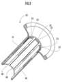
アウターチューブ30は、内壁面に、先端側から基端側にかけて軸方向に案内部33が延設されている。該案内部33は、内壁面に対し円周方向に等間隔に複数設けられている。該案内部33には、レール部材40を挟み込んで取り付けることができる。The
レール部材40は、図3に示すように、首部の下端(外側面)から円周方向に幅狭に延びる底部と、首部の上端(内側面)から円周方向に幅広に延設される頭部とによって、略平底レール形状に形成されている。これに対し、前記案内部33は、図3に示すように、該レール部材40の首部及び底部の外面形状に合致する内面形状を有しているため、上記のとおりレール部材40を挟み込むことができる。As shown in FIG. 3, the
レール部材40は、硬質部30aと同じ又は同等の硬質材、例えばABS、ポリカ-ボネートなどの硬性プラスチックや硬質ゴムなどの硬質材からなり、可撓性を有する長尺体である。The
レール部材40の底部は、外側面に先端側から基端側にかけて軸方向に沿って延設されることで、本発明において、アウターチューブ30の案内部33に係合する被案内部41を構成する。なお、被案内部41の形状は、これに限定されるものではなく、案内部33に係合するものであればよく、軸方向に沿って断続的に設けられていてもよい。The bottom portion of the
さらに、図3に示すように、隣接するレール部材40の頭部と、アウターチューブ30の内周面とよって、本発明における第1係合部42が構成される。Further, as shown in FIG. 3, the head portion of the
レール部材40は、被案内部41が案内部33に係合された状態で、その先端部がアウターチューブ30の先端側の硬質部30aに接着剤などによって固定されているが、レール部材40の他の部分はアウターチューブ30に固定されていない。これにより、アウターチューブ30が屈曲したとき、各レール部材40が夫々摺動しながら追従して屈曲するので、アウターチューブ30の屈曲を妨げない。The
インナーチューブ20は、前記アウターチューブ30の第1係合部42に挟み込まれるように挿入されて取り付けられ、手技に応じてインナーチューブ20の径や数を自由に交換できる。The
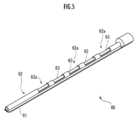
図4に示すように、インナーチューブ20は、可撓性を有する筒状体であり、内視鏡2、鉗子3やメス等の処置具を内部に挿通可能となっている。インナーチューブ20は外周面に親水性加工が施されている。As shown in FIG. 4, the
インナーチューブ20は、本実施形態では、図3に示すように、外径5.3mmのデバイスと、外径3.2mmのデバイス(仮想線で示す)のように外径が異なるものを取り付けてもよく、外径が同じものを取り付けてもよい。In the present embodiment, as shown in FIG. 3, the
インナーチューブ20は、図4に示すように、ポリプロピレン、塩化ビニル等の軟性プラスチック、ゴム等の軟質材から軟質部20aと、軟質部20aより硬質であってABS、ポリカ-ボネートなどの硬性プラスチックや硬質ゴムなどの硬質材からなる硬質部20bとが軸方向に交互に結合されて構成されている。As shown in FIG. 4, the
インナーチューブ20は、図4に示すように、外周面の先端から基端に亘って、第1係合部42に係合して摺動可能とする第2係合部21と、挿入深さを把握するための目盛(図示せず)とを備えている。As shown in FIG. 4, the
第2係合部21は、本実施形態では、インナーチューブ20の外周面に突出する幅広の矩形状の突起であるが、第1係合部42に係合可能であれば任意の形状とすることができる。In the present embodiment, the
第2係合部21は、インナーチューブ20の先端から基端に亘る部分の一部に断続的に設けられている。本実施形態では、先端側と基端側の硬質部20bに夫々設けられている。The
この第2係合部21が、前記アウターチューブ30の第1係合部42に挟み込まれることで、インナーチューブ20はアウターチューブ30に取り付けられる。具体的には、アウターチューブ30の屈曲部31に隣接する第1係合部42に、インナーチューブ20の第2係合部21が取り付けられる。The
このため、本実施形態では、先端側の軟質部20aがアウターチューブ30の屈曲部31の内側に配置されるので、アウターチューブ30を屈曲部31で屈曲させたときに、インナーチューブ20が屈曲を妨げない。For this reason, in this embodiment, since the
また、インナーチューブ20の第2係合部21は、アウターチューブ30の第1係合部42に対して摺動可能であるので、アウターチューブ30が屈曲したとき、各インナーチューブ20が夫々摺動しながら追従して屈曲するので、この構成からもアウターチューブ30の屈曲を妨げない。Moreover, since the 2nd engaging
他方、基端側の軟質部20aは、空気漏れ防止リング32のバルブシートに挿入され、一部がアウターチューブ30の基端から突出する。軟質部20aは屈曲可能であるので、インナーチューブ20を径方向外側に屈曲させることができ、内視鏡2や鉗子の基端部の干渉を回避することができる。On the other hand, the
インナーチューブ20の先端部には、屈曲可能な首振りパイプ22とノーズカバー23が取り付けられている。A
首振りパイプ22は、薄肉のリング状部材を多関節状に連結し、任意の一方向にのみ屈曲可能な可撓性を備えたパイプであり、例えばステンレス管の加工品として構成され、伸直状態から一方向にのみ曲がる屈曲機構として構成することができる。また、首振りパイプ22は、可撓性を有する軟質材からなるパイプや、ABSやポリカーボネート等の硬質プラスチック材からなるリングを連結することで、構成することもできる。The swinging
ノーズカバー23は、首振りパイプ22の先端部に固定されている。ノーズカバー23は、首振りパイプ22と同様、或いはこれより軟質のプラスチック、例えば塩化ビニル等の軟性プラスチック、ゴム等からなっている。ノーズカバー23は軟質材からなるので、組織と接触しても組織に損傷を与えることがない。The
一方、インナーチューブ20の基端部には、スライドパイプ24、スライドノブ25a,25b、スライドストッパー26、と、脱気防止弁27が取り付けられている。On the other hand, a
インナーチューブ20には、ワイヤー部材28a,28bが先端側から基端側にかけて取り付けられている。具体的には、ワイヤー部材28a,28bは、先端部がノーズカバー23に固定され、首振りパイプ22の外側を通過し、硬質部20b、軟質部20a、硬質部20bと軟質部20aの順に軸方向に沿って埋設され、インナーチューブ20の基端部よりも後方に延びて、基端部がスライドノブ25a,25bに固定されている。
スライドノブ25a,25bは、スライドパイプ24に対して摺動自在に構成されている。このため、インナーチューブ20の先端部がアウターチューブ30の先端から突出しているときに、スライドノブ25aを基端側に牽引することで首振りパイプ22を、アウターチューブ30の径方向外側に屈曲させることができる。逆に、スライドノブ25bを基端側に牽引することで首振りパイプ22を、屈曲していない直線状に戻すことができる。The slide knobs 25 a and 25 b are configured to be slidable with respect to the
スライドノブ25a,25bには、スライドパイプ24に向けて延びる貫通孔が設けられ、該貫通孔に挿入される突起部を先端に備えたスライドストッパー26が取り付けられている。The slide knobs 25a and 25b are provided with a through hole extending toward the
このため、スライドノブ25aまたはスライドノブ25bを牽引した状態で、スライドストッパー26を押し込んで、スライドパイプ24に摩擦係合させることで、牽引した所望の位置でスライドノブ25a,25bを係止することができる。For this reason, in a state where the
なお、この首振りパイプ22、スライドノブ25aとワイヤ部材28aが、本発明の第1屈曲操作部に相当する。The
脱気防止弁27は、処置具が挿入されていないインナーチューブ20から体腔、例えば腹腔から空気漏れが生じることを防ぐものである。The
次いで、図3を用いて、アウターチューブ30の屈曲を保持する手段について説明する。Next, means for holding the
前記アウターチューブ30の第1係合部42のうち、インナーチューブ20が取り付けられていない箇所には、ガイド部材60が係合される。The
ガイド部材60は、図3と図5に示すように、第1係合部42に係合される被係合部61が軸方向に沿って形成された長尺の部材である。被係合部61は、本実施形態では、インナーチューブ20の外周面に突出する幅広の矩形状の突起であるが、第1係合部42に係合可能であれば任意の形状とすることができる。As shown in FIGS. 3 and 5, the
ガイド部材60は、略円筒状の本体部62と、本体部62に挿入される軸部63とを備える。The
本体部62は、軸方向に沿って窓部62aが断続的に設けられている。本体部62の基端部は、略扇条でその頂部に円形の孔を有する断面を備えている。本体部62は、インナーチューブ20の硬質部20bと同じ又は同等の硬さの硬質材からなっている。軸部63は、略円柱状であり、針金や銅線などの半硬質材からなる。The
これにより、アウターチューブ30を屈曲部31で屈曲させたときに、軸部63によってアウターチューブ30は屈曲状態で保持される。また、本体部62は窓部62aが設けられているため、屈曲を妨げない。Thus, when the
なお、この屈曲部31とガイド部材60とが、本発明の第3屈曲操作部に相当する。The
図1及びと図6に示すように、インナーチューブ20には、内視鏡2、鉗子3などの処置具が挿入される。1 and 6, treatment tools such as an
内視鏡2及びと鉗子3は、先端部に屈曲可能な屈曲部2a,3aと、基端部に屈曲部2a,3aを屈曲させる操作をする駆動部70を夫々有する。The
駆動部70は、モータ71と、駆動側プーリ72と、ワイヤ73と、従動側プーリ74とを備える。The driving
モータ71のモータ軸は、駆動側プーリ72に接続され、駆動側プーリ72はワイヤ73の一端部が架け渡されている。ワイヤ73は、内視鏡2と鉗子3との内部を夫々軸方向に沿って移動可能に収容され、他端部が従動側プーリ74に架け渡されている。The motor shaft of the
このため、モータ71が回転させると、駆動側プーリ72が回転し、ワイヤ73が移動され、従動側プーリ74回転し、屈曲部2a,3aが屈曲される。For this reason, when the
これにより、内視鏡2の先端に備えられたカメラ2bと鉗子部3bを径方向内側に屈曲させて、被処置部に対向させることができる。Thereby, the
この屈曲部2a,3aと駆動部70とが、本発明の第2屈曲操作部に相当する。The
なお、該モータ71のON/OFF操作部は、手動式であってもよく、機械制御式であってもよい。また、モータを用いることなく、ワイヤを手動で牽引することもできる。The ON / OFF operation unit of the
また、屈曲部2a,3aを屈曲した形状に形成しつつ、直線状に屈曲可能に構成することもできる。つまり、屈曲部2a,3aを曲がっている状態から直線状に伸ばした状態でインナーチューブ20に挿入し、これによれば、内視鏡2を前進させて、屈曲部2a,3aをインナーチューブ20のノーズカバー23から突出させると、屈曲部2a,3aはもとの屈曲した状態に戻るので、駆動部70操作部を設けることなく、屈曲部2a,3aを径方向内側に屈曲させることができる。Further, it is also possible to bendable in a straight line while forming the
次に、図1と図6を参照して、内視鏡治療装置1の使用方法について説明する。本実施形態では、腹腔鏡手術(ラパロ)を行う場合について説明する。但し、内視鏡治療装置1は、他の手術方法、例えば、自然開口部越経管腔的内視鏡手術(NOTES)を行う場合にも使用可能である。Next, a method of using the endoscope treatment apparatus 1 will be described with reference to FIG. 1 and FIG. In this embodiment, a case where laparoscopic surgery (Rapallo) is performed will be described. However, the endoscope treatment apparatus 1 can also be used when performing other surgical methods, for example, natural opening transluminal endoscopic surgery (NOTES).
まず、体壁に形成された開創部に装着され、該開創部の開口状態を維持するとともに該開創部を保護するための開創器80と、該前記開創器80に装着され、該開創器80により形成された開口部から内視鏡治療装置1を導入可能にするとともに腹腔の気密性を維持することができる開創器用バルブキャップ81を取り付ける。First, the
次に、アウターチューブ30にインナーチューブ20を挿入して取り付ける。
本実施形態では、図1に示すように、周方向に60度ずつ離れて、内視鏡2が上方、鉗子3の夫々が左右方向に配置されるように取り付けている。なお、この時点では、インナーチューブ20は、アウターチューブ30の先端から突出せず埋没した状態となっている。Next, the
In the present embodiment, as shown in FIG. 1, the
次に、該インナーチューブ20に内視鏡2、鉗子3を夫々挿入する。このとき、内視鏡2と鉗子3は、インナーチューブ20の先端から突出せず埋没した状態となっている。Next, the
次に、必要に応じ、内視鏡2及びと鉗子3が被処置部Cに対向しやすい角度に、アウターチューブ30を屈曲部31で屈曲させると、ガイド部材60によって該屈曲状態が保持される。Next, if the
以上の準備を行った内視鏡治療装置1を、開創器用バルブキャップ81を介して、体腔内に挿入する。The endoscopic treatment device 1 that has been prepared as described above is inserted into the body cavity via the
次に、インナーチューブ20を前進させ、アウターチューブ30の先端から突出させ、スライドノブ25aを牽引することで、首振りパイプ22をアウターチューブ30の径方向外側に屈曲させる。Next, the
次いで、内視鏡2を前進させ、インナーチューブ20の先端から突出させる。そして、内視鏡用操作部を操作することで、内視鏡2を屈曲部2aで径方向内側に屈曲させて、被処置部Cに対向させる。Next, the
さらに、鉗子3を前進させ、インナーチューブ20の先端から突出させ、処置具用操作部を操作することで、鉗子3を屈曲部3aで径方向内側に屈曲させて、被処置部Cに近づける。Further, the
以上により、準備が完了し、手技を行うことができる。Thus, preparation is completed and the procedure can be performed.
本実施形態の内視鏡治療装置1では、インナーチューブ20によって径方向外側に屈曲させてから、内視鏡2と鉗子3によって径方向内側に屈曲させる。In the endoscope treatment apparatus 1 of the present embodiment, the
これにより、内視鏡2によって被処置部Cを俯瞰的に観察しながら、鉗子3を左右方向から接近させることができるため、視野と作業空間を広くすることができると共に、距離感を掴み易くすることができる。そして、内視鏡2と鉗子3は、径方向内側に屈曲させるために屈曲部を各1つ設ければよいので、多関節化する必要がなく、装置の小型化と低価格化を図ることができる。As a result, the
また、本実施形態の内視鏡治療装置1では、内視鏡2が上方、鉗子3が左右方向に配置されるため、術者が開腹手術をする場合の目と左右の手と同様の位置に配置することができる。そのため、鉗子3をロボット鉗子とし、操作デバイスによってマニュピレータとして動作可能にすれば、術者は開腹手術と同様の感覚で手技を行うことができる。Further, in the endoscope treatment apparatus 1 according to the present embodiment, the
以上、本発明の実施形態について説明したが、本発明はこれに限定されず、形成装置の構成や形態は適宜変更可能である。例えば、アウターチューブ30と複数のレール部材40を一体化させて、第1係合部42を形成してもよい。また、軟質材、硬質材と半硬質材は、同種の樹脂の配合を変化させて軟硬を調節した材料であってもよい。As mentioned above, although embodiment of this invention was described, this invention is not limited to this, The structure and form of a formation apparatus can be changed suitably. For example, the
[変形例]
変形例に係るインナーチューブ120について、図7A乃至図7Cを参照して説明する。[Modification]
An
インナーチューブ120は、先端側から基端側にかけて軸方向に沿って延びる軸断面が扇状の長尺の部材である。The
インナーチューブ120は、先端面から基端面まで、軸方向に貫通孔を有する。貫通孔は、基端から先端方向に向けて、軸方向に沿った直線状案内通路121と、直線状案内通路121の先端に基端が連設され屈曲する屈曲案内通路122とからなる。屈曲案内通路122の先端は、インナーチューブ120の先端面において開口し、開口部123が形成されている。The
したがって、インナーチューブ120に対して、内視鏡2又は鉗子3を挿入し前進させると、内視鏡2と鉗子3は、屈曲案内通路122によって屈曲されたうえで、開口部123から径方向外側に突出される。Therefore, when the
そして、インナーチューブ120は、図7Aに示すように、3個合わせることで略円柱状となるので、内視鏡2と鉗子3は、略放射状に突出される。Then, as shown in FIG. 7A, the three
したがって、インナーチューブ120によれば、簡易な構成で、内視鏡2と鉗子3を径方向外側に屈曲させることができる。Therefore, according to the
1…内視鏡治療装置、2…内視鏡、2a…屈曲部、3…鉗子(処置具)、3a…屈曲部、20…インナーチューブ、21…第2係合部、22…首振りパイプ、25…スライドノブ、28…ワイヤ部材、30…アウターチューブ、31…屈曲部、42…第1係合部、60…ガイド部材、70…駆動部70。DESCRIPTION OF SYMBOLS 1 ... Endoscopic treatment apparatus, 2 ... Endoscope, 2a ... Bending part, 3 ... Forceps (treatment tool), 3a ... Bending part, 20 ... Inner tube, 21 ... 2nd engaging part, 22 ... Swing pipe , 25 ... slide knob, 28 ... wire member, 30 ... outer tube, 31 ... bent part, 42 ... first engaging part, 60 ... guide member, 70 ... drive
Claims (3)
Translated fromJapanese前記内視鏡と前記処置具とを夫々内部に進退自在に挿入可能であり、可撓性を有する複数のインナーチューブと、
複数の前記インナーチューブを挿入可能であるアウターチューブとを備える内視鏡治療装置であって、
前記インナーチューブの夫々の先端部には、前記内視鏡と前記処置具とを前進させたときに、前記アウターチューブの外周方向に向けて、該内視鏡と該処置具とを屈曲させて突出させる第1屈曲操作部が設けられ、
前記内視鏡及びと前記処置具のうち前記インナーチューブから突出する先端部には、前記アウターチューブの内周方向に向けて、該内視鏡及びと該処置具を屈曲させる第2屈曲操作部が夫々設けられていることを特徴とする内視鏡治療装置。An endoscope having flexibility, and a treatment instrument having flexibility used under observation of the endoscope;
A plurality of flexible inner tubes that can be inserted into the endoscope and the treatment instrument so as to freely advance and retract;
An endoscopic treatment apparatus comprising an outer tube into which a plurality of the inner tubes can be inserted,
At the respective distal ends of the inner tubes, when the endoscope and the treatment instrument are advanced, the endoscope and the treatment instrument are bent toward the outer peripheral direction of the outer tube. A first bending operation part to be protruded is provided;
A second bending operation section that bends the endoscope and the treatment instrument toward an inner circumferential direction of the outer tube at a distal end portion protruding from the inner tube of the endoscope and the treatment instrument. Are provided, respectively.
前記アウターチューブの先端と基端との間には、可撓性を有し、屈曲自在かつ屈曲状態で保持可能な第3屈曲操作部が設けられていることを特徴とする内視鏡治療装置。The endoscopic treatment device according to claim 1,
An endoscope treatment apparatus, characterized in that a third bending operation section is provided between the distal end and the proximal end of the outer tube, which is flexible, can be bent and can be held in a bent state. .
前記アウターチューブの内周面には、円周方向に離間して先端側から基端側に軸方向に延びる複数の第1係合部が設けられ、
前記インナーチューブの外周面には、先端側から基端側にかけて軸方向に延び、前記第1係合部に摺動可能に係合する第2係合部が夫々設けられていることを特徴とする内視鏡治療装置。The endoscopic treatment device according to claim 2,
The inner peripheral surface of the outer tube is provided with a plurality of first engaging portions that are spaced apart in the circumferential direction and extend in the axial direction from the distal end side to the proximal end side,
The outer peripheral surface of the inner tube is provided with a second engagement portion that extends in the axial direction from the distal end side to the proximal end side, and slidably engages with the first engagement portion. Endoscopic treatment device.
Priority Applications (3)
| Application Number | Priority Date | Filing Date | Title |
|---|---|---|---|
| PCT/JP2016/050400WO2017119108A1 (en) | 2016-01-07 | 2016-01-07 | Endoscope treatment device |
| JP2017559995AJP6824507B2 (en) | 2016-01-07 | 2016-01-07 | Endoscopic treatment device |
| TW105141847ATW201733517A (en) | 2016-01-07 | 2016-12-16 | Endoscope treatment device |
Applications Claiming Priority (1)
| Application Number | Priority Date | Filing Date | Title |
|---|---|---|---|
| PCT/JP2016/050400WO2017119108A1 (en) | 2016-01-07 | 2016-01-07 | Endoscope treatment device |
Publications (1)
| Publication Number | Publication Date |
|---|---|
| WO2017119108A1true WO2017119108A1 (en) | 2017-07-13 |
Family
ID=59273412
Family Applications (1)
| Application Number | Title | Priority Date | Filing Date |
|---|---|---|---|
| PCT/JP2016/050400CeasedWO2017119108A1 (en) | 2016-01-07 | 2016-01-07 | Endoscope treatment device |
Country Status (3)
| Country | Link |
|---|---|
| JP (1) | JP6824507B2 (en) |
| TW (1) | TW201733517A (en) |
| WO (1) | WO2017119108A1 (en) |
Cited By (3)
| Publication number | Priority date | Publication date | Assignee | Title |
|---|---|---|---|---|
| JP2020146397A (en)* | 2019-03-15 | 2020-09-17 | 学校法人慶應義塾 | Transanal surgical tool introduction device |
| JPWO2020189511A1 (en)* | 2019-03-15 | 2020-09-24 | ||
| JP2022041104A (en)* | 2020-08-31 | 2022-03-11 | 学校法人慶應義塾 | Treatment tool insertion aid |
Citations (10)
| Publication number | Priority date | Publication date | Assignee | Title |
|---|---|---|---|---|
| JPS61276531A (en)* | 1985-05-31 | 1986-12-06 | オリンパス光学工業株式会社 | Insert aid jig of endoscope for colon |
| JP2000325303A (en)* | 1999-05-17 | 2000-11-28 | Olympus Optical Co Ltd | Endoscopic therapeutic device |
| JP2003210398A (en)* | 2002-01-23 | 2003-07-29 | Olympus Optical Co Ltd | Overtube for endoscope |
| WO2004071284A1 (en)* | 2003-02-11 | 2004-08-26 | Olympus Corporation | Overtube, producing method and placing method of the same, and method of treating intra-abdominal cavity |
| JP2005046273A (en)* | 2003-07-31 | 2005-02-24 | Olympus Corp | Overtube for endoscope |
| JP2005287963A (en)* | 2004-04-02 | 2005-10-20 | Olympus Corp | Endoscopic treatment apparatus |
| JP2010220951A (en)* | 2009-03-25 | 2010-10-07 | Olympus Medical Systems Corp | Cover-type treatment endoscope and endoscope cover |
| WO2015107994A1 (en)* | 2014-01-15 | 2015-07-23 | 学校法人慶應義塾 | Surgical tool insertion aid |
| JP2015154895A (en)* | 2014-02-21 | 2015-08-27 | オリンパス株式会社 | surgical manipulator operating device and surgical manipulator system |
| JP5781249B2 (en)* | 2013-08-09 | 2015-09-16 | オリンパス株式会社 | Medical instruments |
Family Cites Families (1)
| Publication number | Priority date | Publication date | Assignee | Title |
|---|---|---|---|---|
| JP4231660B2 (en)* | 2002-05-23 | 2009-03-04 | オリンパス株式会社 | Endoscope |
- 2016
- 2016-01-07WOPCT/JP2016/050400patent/WO2017119108A1/ennot_activeCeased
- 2016-01-07JPJP2017559995Apatent/JP6824507B2/enactiveActive
- 2016-12-16TWTW105141847Apatent/TW201733517A/enunknown
Patent Citations (10)
| Publication number | Priority date | Publication date | Assignee | Title |
|---|---|---|---|---|
| JPS61276531A (en)* | 1985-05-31 | 1986-12-06 | オリンパス光学工業株式会社 | Insert aid jig of endoscope for colon |
| JP2000325303A (en)* | 1999-05-17 | 2000-11-28 | Olympus Optical Co Ltd | Endoscopic therapeutic device |
| JP2003210398A (en)* | 2002-01-23 | 2003-07-29 | Olympus Optical Co Ltd | Overtube for endoscope |
| WO2004071284A1 (en)* | 2003-02-11 | 2004-08-26 | Olympus Corporation | Overtube, producing method and placing method of the same, and method of treating intra-abdominal cavity |
| JP2005046273A (en)* | 2003-07-31 | 2005-02-24 | Olympus Corp | Overtube for endoscope |
| JP2005287963A (en)* | 2004-04-02 | 2005-10-20 | Olympus Corp | Endoscopic treatment apparatus |
| JP2010220951A (en)* | 2009-03-25 | 2010-10-07 | Olympus Medical Systems Corp | Cover-type treatment endoscope and endoscope cover |
| JP5781249B2 (en)* | 2013-08-09 | 2015-09-16 | オリンパス株式会社 | Medical instruments |
| WO2015107994A1 (en)* | 2014-01-15 | 2015-07-23 | 学校法人慶應義塾 | Surgical tool insertion aid |
| JP2015154895A (en)* | 2014-02-21 | 2015-08-27 | オリンパス株式会社 | surgical manipulator operating device and surgical manipulator system |
Cited By (7)
| Publication number | Priority date | Publication date | Assignee | Title |
|---|---|---|---|---|
| JP2020146397A (en)* | 2019-03-15 | 2020-09-17 | 学校法人慶應義塾 | Transanal surgical tool introduction device |
| JPWO2020189511A1 (en)* | 2019-03-15 | 2020-09-24 | ||
| WO2020189511A1 (en)* | 2019-03-15 | 2020-09-24 | 学校法人慶應義塾 | Medical inner tube |
| JP7258271B2 (en) | 2019-03-15 | 2023-04-17 | 慶應義塾 | Transanal surgical instrument introduction device |
| JP7474993B2 (en) | 2019-03-15 | 2024-04-26 | 慶應義塾 | Medical Inner Tubes |
| JP2022041104A (en)* | 2020-08-31 | 2022-03-11 | 学校法人慶應義塾 | Treatment tool insertion aid |
| JP7464923B2 (en) | 2020-08-31 | 2024-04-10 | 慶應義塾 | Treatment tool insertion aid |
Also Published As
| Publication number | Publication date |
|---|---|
| TW201733517A (en) | 2017-10-01 |
| JP6824507B2 (en) | 2021-02-03 |
| JPWO2017119108A1 (en) | 2018-11-01 |
Similar Documents
| Publication | Publication Date | Title |
|---|---|---|
| JP6657244B2 (en) | Robot controlled remote motion center with software and guide tube | |
| US10736702B2 (en) | Activating and rotating surgical end effectors | |
| JP5322098B2 (en) | Insert shroud for surgical instruments | |
| US10433925B2 (en) | Sterile barrier for robotic surgical system | |
| CA3013062C (en) | Devices and methods for suture placement | |
| CN109414281B (en) | Surgical instrument guide with injection channel | |
| US20130012983A1 (en) | Surgical Instrument with Flexible Shaft | |
| JP4856109B2 (en) | Surgical instrument and surgical instrument | |
| JP6432019B2 (en) | Treatment tool insertion aid | |
| EP3269288B1 (en) | Treatment-instrument insertion aid | |
| JP6824958B2 (en) | Medical device including control assembly | |
| JP6824507B2 (en) | Endoscopic treatment device | |
| US20220322916A1 (en) | Device for Aiding in the Positioning and Anchoring of an Endoscope During Gastrointestinal Procedures | |
| JP6982700B2 (en) | Channel unit for endoscopes | |
| JP2011136175A (en) | Endoscope apparatus | |
| US9687270B2 (en) | Instrument system for minimally invasive surgery in single port technology | |
| JP6747800B2 (en) | Treatment tool insertion tool | |
| KR102205181B1 (en) | Trocar | |
| US20250098947A1 (en) | An articulating cannula | |
| WO2016092980A1 (en) | Assist tool and endoscope system | |
| JP7221482B2 (en) | Inner tube | |
| WO2023101755A1 (en) | Device for aiding in the positioning and anchoring of an endoscope during gastrointestinal procedures | |
| JP4350472B2 (en) | Insertion aid for treatment of full-thickness colorectal resection and its medical instrument system |
Legal Events
| Date | Code | Title | Description |
|---|---|---|---|
| 121 | Ep: the epo has been informed by wipo that ep was designated in this application | Ref document number:16883611 Country of ref document:EP Kind code of ref document:A1 | |
| ENP | Entry into the national phase | Ref document number:2017559995 Country of ref document:JP Kind code of ref document:A | |
| NENP | Non-entry into the national phase | Ref country code:DE | |
| 122 | Ep: pct application non-entry in european phase | Ref document number:16883611 Country of ref document:EP Kind code of ref document:A1 |