WO2017113487A1 - Head-mounted device - Google Patents
Head-mounted deviceDownload PDFInfo
- Publication number
- WO2017113487A1 WO2017113487A1PCT/CN2016/074159CN2016074159WWO2017113487A1WO 2017113487 A1WO2017113487 A1WO 2017113487A1CN 2016074159 WCN2016074159 WCN 2016074159WWO 2017113487 A1WO2017113487 A1WO 2017113487A1
- Authority
- WO
- WIPO (PCT)
- Prior art keywords
- headband
- virtual reality
- reality helmet
- pawl
- hook
- Prior art date
- Legal status (The legal status is an assumption and is not a legal conclusion. Google has not performed a legal analysis and makes no representation as to the accuracy of the status listed.)
- Ceased
Links
Images


Classifications
- G—PHYSICS
- G02—OPTICS
- G02B—OPTICAL ELEMENTS, SYSTEMS OR APPARATUS
- G02B27/00—Optical systems or apparatus not provided for by any of the groups G02B1/00 - G02B26/00, G02B30/00
- G02B27/01—Head-up displays
- G02B27/017—Head mounted
- G02B27/0176—Head mounted characterised by mechanical features
- G—PHYSICS
- G02—OPTICS
- G02B—OPTICAL ELEMENTS, SYSTEMS OR APPARATUS
- G02B27/00—Optical systems or apparatus not provided for by any of the groups G02B1/00 - G02B26/00, G02B30/00
- G02B27/01—Head-up displays
- G02B27/0149—Head-up displays characterised by mechanical features
- A—HUMAN NECESSITIES
- A42—HEADWEAR
- A42B—HATS; HEAD COVERINGS
- A42B7/00—Fastening means for head coverings; Elastic cords; Ladies' hat fasteners
- G—PHYSICS
- G02—OPTICS
- G02B—OPTICAL ELEMENTS, SYSTEMS OR APPARATUS
- G02B27/00—Optical systems or apparatus not provided for by any of the groups G02B1/00 - G02B26/00, G02B30/00
- G02B27/01—Head-up displays
- G02B27/0101—Head-up displays characterised by optical features
- G—PHYSICS
- G02—OPTICS
- G02B—OPTICAL ELEMENTS, SYSTEMS OR APPARATUS
- G02B27/00—Optical systems or apparatus not provided for by any of the groups G02B1/00 - G02B26/00, G02B30/00
- G02B27/01—Head-up displays
- G02B27/017—Head mounted
- H—ELECTRICITY
- H04—ELECTRIC COMMUNICATION TECHNIQUE
- H04N—PICTORIAL COMMUNICATION, e.g. TELEVISION
- H04N13/00—Stereoscopic video systems; Multi-view video systems; Details thereof
- H04N13/30—Image reproducers
- H04N13/332—Displays for viewing with the aid of special glasses or head-mounted displays [HMD]
- H04N13/344—Displays for viewing with the aid of special glasses or head-mounted displays [HMD] with head-mounted left-right displays
- G—PHYSICS
- G02—OPTICS
- G02B—OPTICAL ELEMENTS, SYSTEMS OR APPARATUS
- G02B27/00—Optical systems or apparatus not provided for by any of the groups G02B1/00 - G02B26/00, G02B30/00
- G02B27/01—Head-up displays
- G02B27/0101—Head-up displays characterised by optical features
- G02B2027/0132—Head-up displays characterised by optical features comprising binocular systems
- G02B2027/0134—Head-up displays characterised by optical features comprising binocular systems of stereoscopic type
- G—PHYSICS
- G02—OPTICS
- G02B—OPTICAL ELEMENTS, SYSTEMS OR APPARATUS
- G02B27/00—Optical systems or apparatus not provided for by any of the groups G02B1/00 - G02B26/00, G02B30/00
- G02B27/01—Head-up displays
- G02B27/0101—Head-up displays characterised by optical features
- G02B2027/0138—Head-up displays characterised by optical features comprising image capture systems, e.g. camera
- G—PHYSICS
- G02—OPTICS
- G02B—OPTICAL ELEMENTS, SYSTEMS OR APPARATUS
- G02B27/00—Optical systems or apparatus not provided for by any of the groups G02B1/00 - G02B26/00, G02B30/00
- G02B27/01—Head-up displays
- G02B27/0149—Head-up displays characterised by mechanical features
- G02B2027/0154—Head-up displays characterised by mechanical features with movable elements
- G02B2027/0156—Head-up displays characterised by mechanical features with movable elements with optionally usable elements
Definitions
- the inventionrelates to a head mounted device.
- the headsets on the marketneed to be connected to other devices to operate, such as external game consoles, personal computers, mobile phones and other equipment.
- the headsets on the marketare not perfect in implementing human-computer interaction functions. For example, most headsets are uncomfortable to wear, inconvenient to wear, and inconvenient to wear, and cannot be easily accessed when wearing the headset. And other issues.
- the present inventionprovides a headgear device to solve or partially solve the above problems.
- the present inventionprovides a headwear device comprising a virtual reality helmet 1, a control portion 2, a transmission line 4 and a headband portion;
- the virtual reality helmet 1includes a mask close to the face and a display screen at the front end of the mask;
- the control portion 2passes through the transmission line 4 It is integrally connected with the virtual reality helmet 1 for controlling the operation of the headwear device;
- the headband portionis for wearing the virtual reality helmet 1 on the user's head.
- control portion 2includes at least: a signal source for providing a video signal to the display screen, a control panel for use as a human-machine interaction platform, a power source for powering the virtual reality helmet 1 and the control portion 2, and a charging interface 5 For charging the power when the power is insufficient; a wireless connection unit for wirelessly connecting with an external device; and the wireless connection unit including a Bluetooth module and/or a WiFi module.
- the transmission line 4is integrated with a high-speed signal line for transmitting a video signal and current and an earphone signal line for transmitting an audio signal; the transmission line 4 is provided with an earphone holder 3, and the earphone holder 3 is provided with a headphone jack connected to the headphone signal line .
- the head mounted devicefurther includes a microphone 10 and a camera module for picking up a voice signal; the microphone 10 is disposed at a position corresponding to the virtual reality helmet 1 above the mask nose bridge; or the microphone 10 is disposed at the earphone holder of the transmission line 4. 3; the camera module is built in the front end of the virtual reality helmet 1 for collecting video images of the external environment when the virtual reality helmet 1 is not removed.
- the headband portionincludes a rotating headband 6, which is detachably disposed on the left and right sides of the virtual reality helmet 1 by the connecting structure 9, and the rotating headband 6 is rotatable about the virtual reality helmet 1.
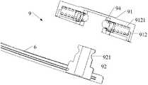
- the connecting mechanism 9includes a rotating shaft 92 and a base 91 located inside the virtual reality helmet 1; the base 91 includes an annular nesting portion 911, a small ball retaining sleeve 94 and at least one shaped receiving groove 912;
- the small ball retaining sleeve 94is embedded and fixed to the inner ring of the nesting portion 911; the open end of the receiving groove 912 is communicated to the nesting portion 911, and the receiving groove 912 is provided with a compression spring 9121, and the receiving groove 912 receives the small ball 93, which is small
- the ball 93is located on the side of the free end of the compression spring 9121; the ball retaining sleeve 94 is provided with a retaining opening 941 corresponding to the open end of each receiving groove 912.
- the small ball 93is held by the small ball retaining sleeve 94.
- the mouth 941is held at the open end of the receiving groove and partially protrudes from the small ball retaining sleeve; one end of the rotating shaft 92 is used for connecting the rotating headband 6, and the other end has a groove 921, and the rotating shaft 92 has a groove under the action of an external force.
- the other endis inserted into the ball retaining sleeve 94, and the small ball 93 protrudes from the groove of the rotating shaft 92 by the portion of the small ball retaining sleeve 94.
- the connecting mechanism 9includes a fixing portion 95 and a hook connecting portion 96;
- the virtual reality helmet 1is provided with a recessed groove, and the main body portion 952 of the fixing portion 95 is rotatably mounted to the bottom wall of the recessed groove by a pin 953
- the main body portion 952is further provided with an arched portion 951;
- the rotating head band 6is provided with an insertion portion 61 that cooperates with the recessed groove, and a counterbore is provided along the extending direction of the insertion portion 61, and the hook is connected.
- the portion 96is mounted in the counterbore, and the hook connecting portion 96 includes a hook fixing member 961, two opposite hook portions 962, a button 963 and a first elastic member 964; wherein the hook fixing member 961 is fixed to the counterbore
- the two hooks half 962are rotatably mounted under the hook fixing member 961 by the pin 965.
- One end of the opposite hook half 962is a driven portion, and the other end is for the fixed portion 95.
- the button 963is relatively slidably mounted on the hook fixing member 961, and the first elastic member 964 is installed between the button 963 and the hook fixing member 961; the button 963 includes the hook fixing member The active part of the 961, the active part moves vertically The two driven portions are operated to further open and close the two engaging portions in the lateral direction to achieve connection and separation with the engaged portion 951.
- the headband portionfurther includes an elastic member 8; the elastic member 8 is disposed at a central position of the rotating headband 6 for symmetrically tightening or relaxing the rotating headband 6.
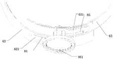
- the swivel headband 6includes two headband halves (62, 63), and the elastic member 8 includes: a cover member 81 enclosing the ends of the two headband halves 62, 63; a long hole in the end portion of the half body 62, 63, a first rack portion 84 is disposed on the upper inner wall of the first long hole 621, and a second rack is disposed on the lower inner wall of the second long hole 631.
- an adjustment knob 83comprising three portions which are reduced in size, the first portion being an adjustment portion (832); and the second portion being an external gear portion 831 passing through the first elongated hole 621 and the second elongated hole 631, and respectively meshed with the first rack portion 84 and the second rack portion 85; the third portion is a mounting portion 833, rotatably mounted on the covering member 81; A pawl ratchet mechanism 86 on the cover 81 for restricting the adjustment knob 83 to only perform one-way rotation.
- the pawl ratchet mechanism 86includes: an inner ratchet portion 861 disposed on an end surface of the adjusting portion 832; a pawl 862 axially movable and limited to be mounted on the covering member 81, and a pawl 862 The end side of the end is provided with a guiding slope 8621; the pressing spring 863 is tightened by the pawl 862 so that the end of the pawl 862 is engaged with the inner ratchet portion 861.
- the adjusting knob 83can pass The guiding slope 8621 performs one-way rotation; and further includes a dial block 864 mounted on the covering member 81 and connected to the pawl 862 for separating the pawl 862 from the inner ratchet portion 861.
- the present inventionprovides a complete head-wearing device, by setting a control portion connected to the virtual reality helmet, so that the head-wearing device of the present invention no longer needs to be connected to other devices, thereby improving the head. Wear the portability and compatibility of the device.
- the present inventionallows the user to more easily insert and remove the earphone by providing an earphone holder on the transmission line; by providing a detachable rotating headband that can be adjusted, angle and tightness, and a detachable length.
- the adjusted adjusting headbandimproves the wearing comfort of the wearing device, so that the wearing device of the invention is more humanized; the invention also strengthens the human-computer interaction capability of the wearing device by setting the microphone and the camera module.
- FIG. 1is a schematic overall view of a headset provided in Embodiment 1;
- FIG. 2is a rear view of the headset provided in Embodiment 1;
- FIG. 3ais a schematic diagram of a connection mechanism provided in Embodiment 2;
- FIG. 3ais a schematic diagram of a connection mechanism provided in Embodiment 2;
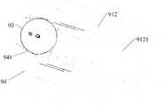
- FIG. 3bis a schematic view showing a state in which the small ball provided by the second embodiment is held by the small ball retaining sleeve at the open end of the receiving groove under the action of the compression spring;
- Figure 3cis a schematic view showing the state in which the rotating shaft of the second embodiment is inserted into the small ball retaining sleeve;
- Figure 3dis a schematic view of a connection mechanism having four receiving slots provided in the second embodiment
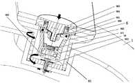
- FIG. 4ais a schematic diagram of another connection mechanism provided in Embodiment 2;
- Figure 4bis a cross-sectional view of the connecting mechanism of Figure 4a taken along the dashed line of Figure A-A;
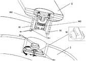
- Figure 4cis a schematic view of the connecting mechanism provided in the second embodiment after disassembly
- 4dis a schematic structural view of a first hook connecting portion provided in the second embodiment
- FIG. 4eis a schematic structural view of a second hook connecting portion provided in Embodiment 2;
- 4fis a schematic structural view of a third hook connecting portion provided in Embodiment 2;
- 4gis a schematic structural view of a fourth type of hook connecting portion provided in the second embodiment
- FIG. 5ais a schematic structural diagram of a headgear device according to Embodiment 3.
- Figure 5bis an exploded structural view of the elastic member provided in the third embodiment
- Figure 5cis a schematic view showing the connection state of the elastic member and the rotary head provided in the third embodiment
- Figure 5dis a partial cross-sectional view of the pawl of the elastic member of Figure 5b mated with the ratchet structure.
- the left and right direction and the up and down directionare defined in the normal wearing state of the headwear device, and the left and right direction of the headwear device is the direction of the length of the display screen.
- the up and down direction of the headsetis the direction of the width of the display.
- Embodiment 1Wearing equipment
- FIG. 1is a schematic view of a head-mounted device according to a first embodiment of the present invention.
- FIG. 2is a rear view of the head-mounted device according to the first embodiment.
- the head-wearing device of the first embodimentincludes Virtual reality helmet 1, control section 2, transmission line 4 and headband section.
- the virtual reality helmet 1includes a mask close to the face and a display screen located at the front end of the mask; the control portion 2 is integrally connected with the virtual reality helmet 1 through the transmission line 4 for controlling the operation of the headset; the headband portion is for virtualizing The realistic helmet 1 is worn on the user's head.
- control portion 2includes at least: a signal source for providing a video signal to the display screen, a control panel for use as a human-machine interaction platform, and a power source for powering the virtual reality helmet 1 and the control portion 2
- the charging interface 5is used to charge the power source when the power source is insufficient.
- control part 2 of the head mounted devicecan be designed as a smart box integrating the above signal source, control panel, power supply and charging interface, and the head mounted device is controlled by the smart box.
- control portion 2may further include a wireless connection unit for wirelessly connecting with an external device; for example, the control portion 2 is wirelessly connected to the game machine as an ordinary game controller to realize external to the game machine or the like. Control of the device; wherein the wireless connection unit comprises a Bluetooth module and/or a WiFi module.
- the earphone holderis disposed on the transmission line.
- the control portion 2is connected to the virtual reality helmet 1 through a transmission line 4, and the transmission line 4 is integrated with a high-speed signal line for transmitting a video signal and a current and a headphone signal line for transmitting an audio signal;
- the transmission line 4is provided with an earphone holder 3, and an earphone
- the socket 3is provided with a headphone jack connected to the signal line of the earphone, so that the user can conveniently insert and remove the earphone through the earphone holder on the transmission line.
- the headsetfurther includes a microphone and a camera module, and the microphone is used for providing voice input during human-computer interaction, and the camera module
- the groupis able to observe the external situation at any time under the control of the user.
- the microphone 10 for picking up a voice signalcan be placed on the earphone holder 3 of the transmission line 4 for use as a line control input.
- the microphone 10can also be disposed at a position corresponding to the mask of the virtual reality helmet 1 corresponding to the nose of the mask, not only capable of receiving clear and noise-free voice, but also setting the microphone above the nose bridge of the virtual reality helmet without affecting Exterior.
- the camera moduleis built in the front end of the virtual reality helmet 1 for collecting a video image of the external environment when the virtual reality helmet 1 is not removed, and displaying the video image of the collected external environment.
- the video image captured by the camera modulecan be used as an input to the video game.
- the headband portionincludes a rotating headband 6, and the rotating headband 6 is detachably disposed in the virtual reality by the connecting mechanism 9.
- the left and right sides of the helmet 1can be disassembled by simple drawing, which is convenient to use and improves the portability of the wearing device; and the rotating headband 6 can be rotated around the virtual reality helmet 1 so that different head types are The user can find a suitable wearing angle and increase the wearing comfort.
- Embodiment 2Implementation scheme of the connection mechanism
- the attachment mechanism 9includes a shaft 92 and a base 91 located inside the virtual reality helmet 1.
- the base 91includes an annular nesting portion 911, a ball retaining sleeve 94 and at least one shaped receiving slot 912 into which the ball retaining sleeve 94 is embedded and secured.
- the open end of the receiving groove 912communicates with the nesting portion 911.
- the receiving groove 912is provided with a compression spring 9121.
- the receiving groove 912receives the small ball 93, and the small ball 93 is located on the side of the free end of the compression spring 9121.
- the small ball retaining sleeve 94is provided with a retaining opening 941 corresponding to the open end of each receiving groove 912. Under the action of the compression spring 9121, the small ball 93 is held by the retaining opening 941 of the small ball retaining sleeve 94.
- the inner sideis the side facing the rotating shaft; preferably, when the small ball retaining sleeve 94 has a certain thickness, the retaining opening 941 is a variable diameter opening.
- the holding port 941 in this embodimentmay also be an equal-diameter port, and the diameter of the equal-diameter port is smaller than the diameter of the small ball 93; preferably, when the small-ball retaining sleeve 94 is thin, the holding port 941 is an equal-diameter port. .
- one end of the shaft 92is used to connect the rotating headband 6, and the other end has a groove 921 adapted to the portion of the ball 93 that protrudes from the ball retaining sleeve.
- the other end of the rotating shaft 92 having the groove 921is inserted into the ball retaining sleeve 94, and the portion of the small ball 93 protruding from the small ball retaining sleeve 94 is engaged with the groove 921 of the rotating shaft 92.
- FIG. 3aonly the circular arc-shaped groove 921 is schematically illustrated.
- the groove 921 in this embodimentmay also be rectangular or trapezoidal as long as the groove 921 can protrude from the small ball 93 to the small ball.
- the protruding portion of the retaining sleeveis fitted, and the stable shaft of the rotating shaft is embedded in the small ball retaining sleeve 94.
- the rotating headbandcan be fixed to the left and right sides of the virtual reality helmet by the following method: under the action of an external force, such as pressing the rotating headband 6, the end of the rotating shaft 92 having the groove 921 is inserted into the small ball retaining sleeve. In the 94, until the groove 921 of the rotating shaft 92 and the portion of the small ball 93 protruding from the small ball retaining sleeve 94 are just engaged, the rotating shaft 92 cannot be detached from the base 91 due to the blocking of the small ball 93, and the rotating headband 6 and the base are realized. 91 connection. Since the surface of the small ball 93 is smooth, the inner surface of the small ball retaining sleeve 94 is smooth, so that the rotating headband 6 can freely rotate in the small ball retaining sleeve 94 under the action of an external force.
- an external forcesuch as pressing the rotating headband 6
- the end of the rotating shaft 92 having the groove 921is inserted into the small ball retaining s
- the rotating headbandcan be detached from the virtual reality helmet by the following method: under the action of an external force, such as pulling the rotating headband 6 to the outside, the groove 921 on the rotating shaft 92 is separated from the small ball 93, The small ball 93 retreats under the action of the thrust of the rotating shaft 92. When the small balls 93 are all retracted into the accommodating groove 912, the rotating headband 6 drives the rotating shaft 92 to be separated from the base 91.
- the base 91preferably includes an even number of receiving slots 912, and an even number of receiving slots 912 are symmetrically distributed around the nesting portion 911. As shown in FIG. 3d, the base 91 is provided with four receiving grooves uniformly and symmetrically distributed around the nesting portion 911.
- the attachment mechanism 9includes a fixed portion 95 and a hook attachment portion 96; as shown in Figures 4a and 4b, the virtual reality helmet 1 is provided with a recessed slot
- the main body portion 952 of the fixing portion 95is rotatably mounted on the bottom wall of the recessed groove by the pin 953, the main The body portion 952 is further provided with an arched portion 951;
- the rotating head band 6is provided with an insertion portion 61 that cooperates with the recessed groove, and a counterbore is provided along the extending direction of the insertion portion 61, and the hook connecting portion 96 Mounted in the counterbore, the hook connecting portion 96 includes a hook fixing member 961, two opposite hooking halfs 962, a button 963 and a first elastic member 964;
- the hook fixing member 961is fixed on the step of the counterbore; the two hook half 962 are rotatably mounted under the hook fixing member 961 through the pin 965, and one end of the opposite hook half 962 is a driven portion, and One end is a locking portion for connecting with the fixing portion 95; the button 963 is relatively slid and is mounted on the hook fixing member 961, and the first elastic member 964 is mounted between the button 963 and the hook fixing member 961;
- the button 963includes an active portion passing through the hook fixing member 961. The active portion moves in the vertical direction to drive the two driven portions, thereby causing the two engaging portions to open and close in the lateral direction to achieve connection and separation with the engaged portion 951.
- the active portion of the button 963is not connected to the driven portion of the two hook half bodies 962, and the active portion is in contact with the driven portion but is not connected;
- a second elastic member 971 for resettingis provided between the retaining portions of the body 962, and the coupling mechanism 9 includes a limiting structure for defining the upward displacement of the button 963. Specifically, as shown in FIG.
- the limiting structureincludes: a through hole provided on the hook fixing member 961; a thread blind hole provided on the button 963; and a bolt 972 passing through the hook from the bottom to the top
- the through hole on the fixing member 961is screwed to the threaded blind hole on the button 963; or, as shown in FIG. 4e, the limiting structure includes a limiting plate 975 fixed on the end of the active portion, the limiting plate The 975 is blocked by the follower of at least one of the hook halves 962 when moving up to the maximum displacement.
- the active portion of the button 963is movably connected to the driven portion of the two hook half bodies 962, and the active portion moves in the vertical direction to drive the two driven portions.
- the pin/pin 965is rotated in the forward/reverse direction.
- the manner in which the active portion and the driven portion are movably connectedmay be any one of the following: as shown in FIG. 4f, the active portion is provided with a mounting slot 973, and the ends of the two driven portions are respectively inserted into the mounting slot 973. And the two driven portions have a moving gap in the mounting groove 973, so that when the active portion moves in the vertical direction, the two driven portions can be driven to rotate in the forward/reverse direction around the pin 965.
- the active portionis provided with a circular hole
- the ends of the two driven portionsare respectively provided with long holes 974, which are installed through the circular holes on the active portion and the long holes 974 on the two driven portions.
- There is a pin 965such that when the main portion moves in the vertical direction, the two followers can be driven to rotate in the forward/reverse direction around the pin 965.
- the first elastic member 964may be specifically a spring, which can be expanded and contracted in the first direction shown in FIG. 4a, and the button 963 is pressed down (in the direction of the arrow shown in FIG. 4b), and the pressure can be eliminated. Re-bounce back to the natural state.
- the button 963when the button 963 receives the pressure in the first direction and downward, the first elasticity The member 964 is compressed, the button 963 controls the active portion of the card to slide downward, and the driven portion of the two hook half 962 is slid by the active portion to slide, and the sliding portion of the two hook half 962 is controlled by the sliding of the driven portion. Opening in the second direction shown in FIG. 4a, the separation from the fixing portion 95 is achieved; that is, the detachment of the hook connecting portion 96 of the connecting mechanism 9 from the fixing portion 95 is realized, thereby realizing the virtual reality helmet 1 and the rotating headband 6 Detachment.
- the first elastic member 964is stretched and restored to the original length, and the extension control button 963 of the first elastic member 964 slides upward in the first direction, thereby driving the active portion to slide upward through the active portion.
- the slidecontrols the sliding of the follower portions of the two hook halves 962, and further controls the engagement with the fixed portion 95 by controlling the sliding of the follower portions to close the latching portions of the hook portions.
- the face A1 in the insertion portion 61 of the headband 6is rotated, and the face A1 and the face A2 in the groove in the main body portion 952 are matched with each other; here, when the main body portion 952 is set in a circular shape, the face A2 and the face A1 After the mutual matching and matching, the synchronous rotation of the rotating headband 6 and the fixed portion 95 can be realized, so that the free rotation of the rotating headband 6 with respect to the virtual reality helmet 1 can be realized by the connecting mechanism 9.
- Embodiment 3Headband portion
- the headband portionincludes an elastic member 8 for symmetrically tightening and relaxing the rotating headband 6, facilitating the user to adjust the tightness of the wearing of the headgear device and improving the user experience.
- the swivel headband 6includes two headband halves 62 and 63
- the elastic member 8includes: a cover member 81 enclosing the ends of the two headband halves 62 and 63; respectively disposed on the two headbands
- the long holes in the ends of the half bodies 62 and 63are provided with a first rack portion 84 on the upper inner wall of the first long hole 621, and a second rack portion on the lower inner wall of the second long hole 631.
- an adjustment knob 83comprising three portions which are reduced from large to large, the first portion being the adjustment portion 832; the second portion being the outer gear portion 831 passing through the first elongated hole 621 and the second elongated hole 631, and Engaged with the first rack portion 84 and the second rack portion 85 respectively; the third portion is a mounting portion 833 that is rotatably mounted on the covering member 81; and further includes a cover member 81 for limiting
- the adjustment knob 83can only perform the one-way rotation of the pawl ratchet mechanism 86.
- the one-way rotation of the adjustment knob 83is for tightening the rotating headband 6.
- the toggle block 864When the user wears, the toggle block 864 should first be turned to break the engagement relationship of the pawl ratchet mechanism 86, and then the adjustment portion 832 is rotated in the first direction, for example, the adjustment portion 832 is rotated counterclockwise, or by two The headband halves 62 and 63 are pulled outward. Due to the cooperation of the outer gear portion 831 with the first rack portion 84 and the second rack portion 85, the two headband halves are synchronously reversely moved to achieve the looseness of the rotating headband 6. Open, and then toggle the toggle block 864 to continue the engagement of the pawl ratchet mechanism 86.
- the adjustment portion 832is rotated in the second direction, for example, the adjustment portion 832 is rotated clockwise, or by pushing the two headband halves 62 and 63 inwardly, due to the outer gear portion 831 and the first rack portion 84.
- the two headband halvesmove in opposite directions to achieve the tightening of the rotating headband 6, so that the helmet is secured to the human head.
- the adjustment knob 83is restricted from being unidirectionally rotated, so that the rotary headband 6 does not become loose.
- the pawl ratchet mechanism 86includes: an inner ratchet portion 861 disposed on an end surface of the adjusting portion 832;
- the pawl 862 on the cover 81is provided with a guiding slope 8621 on one end side of the pawl 862; a compression spring 863 for tightening the pawl 862 so that the end of the pawl 862 is engaged with the inner ratchet portion 861, the pawl 862 and After the inner ratchet portion 861 is engaged, the adjusting knob 83 can be unidirectionally rotated by the guiding inclined surface 8621; and further includes a dialing block 864 mounted on the covering member 81 and connected to the pawl 862, the dialing block 864 Used to separate the pawl 862 from the inner ratchet portion 861.
- the compression spring 863tightens the pawl 862 such that the end of the pawl 862 engages with the inner ratchet portion 861.
- the adjustment knob 83can only perform one-way rotation, which is adjusted in this embodiment.
- the knob 83can only rotate clockwise to tighten the rotating headband 6; when it is necessary to break the engagement state of the ratchet ratchet mechanism 86, the toggle block 864 is pushed to drive the pawl 862 to move to the end and the inner end.
- the ratchet portion 861can be detached.
- the headgear portionfurther includes an adjustment headband 7.
- an adjustment headband 7Referring to FIG. 1 and FIG. 2, one end of the adjustment headband 7 is detachably connected at an intermediate position above the virtual reality helmet 1, and the adjustment headband can be disassembled by simple pressing, which is convenient to take, and improves the portability of the headwear device;
- the other end of the adjusting headband 7passes through the hole in the middle of the upper portion of the elastic member 8, and is fixed by Velcro bonding.
- the design of the Velcro structureis convenient for controlling the length of the adjusting headband, thereby improving the stability and comfort of the wearing of the wearing device.
- the present inventionprovides a brand new layout of the headset: 1. By setting a control portion connected to the virtual reality helmet, the headset of the present invention no longer needs to be connected to other devices, thereby improving the wearing of the headset.
- the present inventionallows the user to more easily insert and remove the earphone by setting the earphone holder on the transmission line; 3. by providing a detachable rotating headband that can be adjusted, angle and tightness, and The detachable adjustable length adjustable headband is provided to improve the wearing comfort of the wearing device, so that the wearing device of the invention is more humanized; 4.
- the inventionalso provides a microphone and a camera module. Strong human-computer interaction capabilities of the headset.
Landscapes
- Physics & Mathematics (AREA)
- General Physics & Mathematics (AREA)
- Optics & Photonics (AREA)
- Engineering & Computer Science (AREA)
- Multimedia (AREA)
- Signal Processing (AREA)
- Helmets And Other Head Coverings (AREA)
Abstract
Description
Translated fromChinese本发明涉及一种头戴设备。The invention relates to a head mounted device.
发明背景Background of the invention
目前,市面上存在的大多数头戴设备需外接其他设备才能运转,如外接游戏机、个人电脑、手机等设备。并且,市面上的头戴设备在人机交互功能实现上也不够完善,如多数头戴设备存在佩戴不舒适、佩戴调节不便利、耳机佩戴不便利、穿戴该头戴设备时无法方便获取外界信息等问题。At present, most of the headsets on the market need to be connected to other devices to operate, such as external game consoles, personal computers, mobile phones and other equipment. Moreover, the headsets on the market are not perfect in implementing human-computer interaction functions. For example, most headsets are uncomfortable to wear, inconvenient to wear, and inconvenient to wear, and cannot be easily accessed when wearing the headset. And other issues.
发明内容Summary of the invention
鉴于上述问题,本发明提供了一种头戴设备,以解决或部分地解决上述问题。In view of the above problems, the present invention provides a headgear device to solve or partially solve the above problems.
为达到上述目的,本发明的技术方案是这样实现的:In order to achieve the above object, the technical solution of the present invention is achieved as follows:
本发明提供了一种头戴设备,包括虚拟现实头盔1,控制部分2、传输线4和头带部分;虚拟现实头盔1包括贴近面部的面罩和位于面罩前端的显示屏;控制部分2通过传输线4与虚拟现实头盔1一体连接,用于控制头戴设备的运行;头带部分,用于将虚拟现实头盔1穿戴在使用者头部。The present invention provides a headwear device comprising a
优选地,控制部分2至少包括:信号源,用于为显示屏提供视频信号;控制面板,用于作为人机交互平台;电源,用于为虚拟现实头盔1和控制部分2供电;充电接口5,用于当电源电量不足时,为电源充电;无线连接单元,用于与外部设备无线连接;无线连接单元包括蓝牙模块和/或WiFi模块。Preferably, the
优选地,传输线4集成有用于传输视频信号和电流的高速信号线和用于传输音频信号的耳机信号线;传输线4设置有耳机座3,耳机座3设置有与耳机信号线连接的耳机插孔。Preferably, the
进一步优选地,头戴设备还包括用于拾取语音信号的麦克风10和摄像机模组;麦克风10设置在虚拟现实头盔1相应于面罩鼻梁上方的位置处;或者,麦克风10设置在传输线4的耳机座3上;摄像机模组内置在虚拟现实头盔1的前端,用于在不取下虚拟现实头盔1时采集外界环境的视频图像。Further preferably, the head mounted device further includes a
优选地,头带部分包括旋转头带6,旋转头带6通过连接结构9可拆卸地设置在虚拟现实头盔1的左右两侧,且旋转头带6可绕虚拟现实头盔1旋转。Preferably, the headband portion includes a rotating
在一优选实施例中,连接机构9包括转轴92和位于虚拟现实头盔1内部的底座91;底座91包括一环形的嵌套部911、一小球保持套94和至少一条形的容纳槽912;小球保持套94嵌入并固定在嵌套部911的内环;容纳槽912的开口端连通到嵌套部911,容纳槽912内设置有压缩弹簧9121,容纳槽912中收容小球93,小球93位于压缩弹簧9121的自由端所在侧;小球保持套94对应每个容纳槽912的开口端设置有保持口941,在压缩弹簧9121作用下,小球93被小球保持套94的保持口941卡持在容纳槽的开口端并且部分突出于所述小球保持套;转轴92一端用于连接旋转头带6,另一端具有沟槽921,在外力作用下,转轴92具有沟槽的另一端插入小球保持套94内,小球93突出于小球保持套94的部分卡入到转轴92的沟槽。In a preferred embodiment, the
在另一优选实施例中,连接机构9包括固定部分95和卡勾连接部分96;虚拟现实头盔1上设有凹陷槽,固定部分95的主体部分952通过销钉953转动安装于凹陷槽的底壁上,主体部分952上还设有拱形的被卡持部951;旋转头带6上设有与凹陷槽配合的插入部61,沿着插入部61的延伸方向设有沉孔,卡勾连接部分96安装于沉孔内,卡勾连接部分96包括卡勾固定件961、两相对设置的卡勾半体962、按钮963和第一弹性件964;其中,卡勾固定件961固定于沉孔的台阶上;两卡勾半体962通过销轴965转动安装于卡勾固定件961的下方,相对设置的卡勾半体962的一端为从动部,另一端为用于与固定部分95进行连接的卡持部;按钮963相对滑动且限位安装于卡勾固定件961上,且按钮963与卡勾固定件961之间安装有第一弹性件964;按钮963包括穿过卡勾固定件961的主动部,主动部在竖向上移动驱动两从动部动作,进而使两卡持部在横向上开合实现与被卡持部951的连接与分离。In another preferred embodiment, the
优选地,头带部分还包括松紧部件8;松紧部件8设置在旋转头带6的中部位置,用于对称收紧或放松旋转头带6。Preferably, the headband portion further includes an
在一优选实施例中,旋转头带6包括两个头带半体(62、63),松紧部件8包括:包裹两个头带半体62,63端部的包覆件81;分别设于两个头带半体62,63端部上的长孔,在第一个长孔621的上部内壁上设有第一齿条部分84,在第二个长孔631的下部内壁上设有第二齿条部分85;调节旋钮83,包括由大变小的三个部分,第一部分为调节部(832);第二部分为外齿轮部831,其穿过第一个长孔621和第二个长孔631,且分别与第一齿条部分84和第二齿条部分85相啮合;第三部分为安装部833,转动安装于所述包覆件81上;还包括设于包覆件81上的用于限制调节旋钮83只能进行单向旋转的棘爪棘轮机构86。In a preferred embodiment, the
进一步优选地,棘爪棘轮机构86包括:设于所述调节部832的端面上的内棘轮部861;轴向移动且限位安装于所述包覆件81上的棘爪862,棘爪862的端部一侧设有导向斜面8621;将棘爪862顶紧使得棘爪862端部与内棘轮部861啮合的压簧863,棘爪862与内棘轮部861啮合后,调节旋钮83可以通过所述导向斜面8621进行单向旋转;还包括安装于包覆件81上与棘爪862连接的拨动块864,所述拨动块864用于使棘爪862与内棘轮部861分离。Further preferably, the
本发明实施例的有益效果是:本发明提供了一种完整的头戴设备,通过设置与虚拟现实头盔连接的控制部分,使得本发明的头戴设备不再需要外连其他设备,提高了头戴设备的便携性和兼容性。The beneficial effects of the embodiments of the present invention are: the present invention provides a complete head-wearing device, by setting a control portion connected to the virtual reality helmet, so that the head-wearing device of the present invention no longer needs to be connected to other devices, thereby improving the head. Wear the portability and compatibility of the device.
在优选方案中,本发明通过在传输线设置耳机座,使用户能够更加方便的插拔耳机;通过设置可拆卸的、角度和松紧度均可调整的旋转头带,以及设置可拆卸的、长度可调整的调节头带,提高头戴设备佩戴舒适性,使得本发明的头戴设备更为人性化;本发明还通过设置麦克风和摄像模组加强头戴设备的人机交互能力。In a preferred embodiment, the present invention allows the user to more easily insert and remove the earphone by providing an earphone holder on the transmission line; by providing a detachable rotating headband that can be adjusted, angle and tightness, and a detachable length. The adjusted adjusting headband improves the wearing comfort of the wearing device, so that the wearing device of the invention is more humanized; the invention also strengthens the human-computer interaction capability of the wearing device by setting the microphone and the camera module.
上述说明仅是本发明技术方案的概述,为了能够更清楚了解本发明的技术手段,而可依照说明书的内容予以实施,并且为了让本发明的上述和其它目的、特征和优点能够更明显易懂,以下特举本发明的具体实施方式。The above description is only an overview of the technical solutions of the present invention, and the above-described and other objects, features and advantages of the present invention can be more clearly understood. Specific embodiments of the invention are set forth below.
附图简要说明BRIEF DESCRIPTION OF THE DRAWINGS
通过阅读下文优选实施方式的详细描述,各种其他的优点和益处对于本领域普通技术人员将变得清楚明了。附图仅用于示出优选实施方式的目的,而并不认为是对本发明的限制。而且在整个附图中,用相同的参考符号表示相同的部件。在附图中:Various other advantages and benefits will become apparent to those skilled in the art from a The drawings are only for the purpose of illustrating the preferred embodiments and are not to be construed as limiting. Throughout the drawings, the same reference numerals are used to refer to the same parts. In the drawing:
图1为实施例一提供的头戴设备整体示意图;1 is a schematic overall view of a headset provided in
图2为实施例一提供的头戴设备后视图;2 is a rear view of the headset provided in
图3a为实施例二提供的一种连接机构示意图;FIG. 3a is a schematic diagram of a connection mechanism provided in
图3b为实施例二提供的小球在压缩弹簧的作用下,被小球保持套卡持在容纳槽开口端的状态示意图;FIG. 3b is a schematic view showing a state in which the small ball provided by the second embodiment is held by the small ball retaining sleeve at the open end of the receiving groove under the action of the compression spring;
图3c为实施例二提供的转轴插入小球保持套内的状态示意图;Figure 3c is a schematic view showing the state in which the rotating shaft of the second embodiment is inserted into the small ball retaining sleeve;
图3d为实施例二提供的具有4个容纳槽的连接机构示意图;Figure 3d is a schematic view of a connection mechanism having four receiving slots provided in the second embodiment;
图4a为实施例二提供的另一种连接机构示意图;4a is a schematic diagram of another connection mechanism provided in
图4b为图4a的连接机构沿图A-A虚线的剖面图;Figure 4b is a cross-sectional view of the connecting mechanism of Figure 4a taken along the dashed line of Figure A-A;
图4c为实施例二提供的连接机构拆卸后的示意图;Figure 4c is a schematic view of the connecting mechanism provided in the second embodiment after disassembly;
图4d为实施例二提供的第一种卡勾连接部分结构示意图;4d is a schematic structural view of a first hook connecting portion provided in the second embodiment;
图4e为实施例二提供的第二种卡勾连接部分结构示意图;4e is a schematic structural view of a second hook connecting portion provided in
图4f为实施例二提供的第三种卡勾连接部分结构示意图;4f is a schematic structural view of a third hook connecting portion provided in
图4g为实施例二提供的第四种卡勾连接部分结构示意图;4g is a schematic structural view of a fourth type of hook connecting portion provided in the second embodiment;
图5a为实施例三提供的头戴设备的结构示意图;FIG. 5a is a schematic structural diagram of a headgear device according to
图5b为实施例三提供的松紧部件爆炸结构图;Figure 5b is an exploded structural view of the elastic member provided in the third embodiment;
图5c为实施例三提供的松紧部件与旋转头戴的连接状态示意图;Figure 5c is a schematic view showing the connection state of the elastic member and the rotary head provided in the third embodiment;
图5d为图5b中的松紧部件的棘爪与棘轮结构配合的局部剖面图。Figure 5d is a partial cross-sectional view of the pawl of the elastic member of Figure 5b mated with the ratchet structure.
为使本发明的目的、技术方案和优点更加清楚,下面将结合附图对本发明实施方式作进一步地详细描述。The embodiments of the present invention will be further described in detail below with reference to the accompanying drawings.
首先,对具体实施方式中涉及到的方位词语作一简要说明:本实施例中以头戴设备正常佩戴状态下定义其左右方向和上下方向,头戴设备的左右方向为显示屏的长度所在方向,头戴设备的上下方向为显示屏的宽度所在方向。First, a brief description of the orientation words involved in the specific embodiment is given. In this embodiment, the left and right direction and the up and down direction are defined in the normal wearing state of the headwear device, and the left and right direction of the headwear device is the direction of the length of the display screen. The up and down direction of the headset is the direction of the width of the display.
实施例一:头戴设备Embodiment 1: Wearing equipment
图1为本实施例一提供的头戴设备整体示意图,图2为本实施例一提供的头戴设备后视图,如图1和图2共同所示,本实施例一的头戴设备,包括虚拟现实头盔1、控制部分2、传输线4和头带部分。其中,虚拟现实头盔1包括贴近面部的面罩和位于面罩前端的显示屏;控制部分2通过传输线4与虚拟现实头盔1一体连接,用于控制头戴设备的运行;头带部分,用于将虚拟现实头盔1穿戴在使用者头部。1 is a schematic view of a head-mounted device according to a first embodiment of the present invention. FIG. 2 is a rear view of the head-mounted device according to the first embodiment. As shown in FIG. 1 and FIG. 2, the head-wearing device of the first embodiment includes
在一优选实施方式中,控制部分2至少包括:信号源,用于为显示屏提供视频信号;控制面板,用于作为人机交互平台;电源,用于为虚拟现实头盔1和控制部分2供电;充电接口5,用于当电源电量不足时,为电源充电。In a preferred embodiment, the
如图1所示,在实际应用中,可以将头戴设备的控制部分2设计为一个集成上述信号源、控制面板、电源、充电接口的智能盒子,通过该智能盒子控制头戴设备。As shown in FIG. 1 , in a practical application, the
在另一优选实施方式中,控制部分2还可以包括无线连接单元,用于与外部设备无线连接;如将控制部分2作为一个普通的游戏手柄,无线连接到游戏机,实现对游戏机等外部设备的控制;其中,无线连接单元包括蓝牙模块和/或WiFi模块。In another preferred embodiment, the
为了方便头戴设备的耳机插拔,在一个实现方案中,在传输线上设置耳机座。具体的,控制部分2通过传输线4连接到虚拟现实头盔1,传输线4集成有用于传输视频信号和电流的高速信号线和用于传输音频信号的耳机信号线;传输线4设置有耳机座3,耳机座3设置有与耳机信号线连接的耳机插孔,使得用户可以较方便地通过传输线上的耳机座实现耳机的插拔。In order to facilitate the plugging and unplugging of the headset of the headset, in one implementation, the earphone holder is disposed on the transmission line. Specifically, the
为了丰富本发明头戴设备的功能、更好地进行人机交互,在另一个实现方案中,头戴设备还包括麦克风和摄像模组,麦克风用于提供人机交互时的语音输入,摄像模组能够在用户控制下随时观察外部情况。具体的,可以将用于拾取语音信号的麦克风10设置在传输线4的耳机座3上,作为一个线控输入使用。参考图2所示,也可以将麦克风10设置在虚拟现实头盔1相应于面罩鼻梁上方的位置处,不但能够接收清晰无杂音的语音,而且将麦克风设置在虚拟现实头盔的面罩鼻梁上方,不影响外观。摄像机模组内置在虚拟现实头盔1的前端,用于在不取下虚拟现实头盔1时采集外界环境的视频图像,并对采集的外界环境的视频图像进行显示。在实际应用中,可以将摄像机模组采集的视频图像作为视频游戏的输入。In order to enrich the function of the headset of the present invention and better perform human-computer interaction, in another implementation, the headset further includes a microphone and a camera module, and the microphone is used for providing voice input during human-computer interaction, and the camera module The group is able to observe the external situation at any time under the control of the user. Specifically, the
为了提高头戴设备佩戴的舒适度,如图1和图2所示,在再一个实现方案中,头带部分包括旋转头带6,旋转头带6通过连接机构9可拆卸地设置在虚拟现实头盔1的左右两侧,通过简单的拉拔即可拆卸旋转头带,取用方便,且提高头戴设备的便携性;且旋转头带6可绕虚拟现实头盔1旋转,使得不同头型的使用者能够找到合适的佩戴角度,增加佩戴的舒适度。In order to improve the wearing comfort of the wearing device, as shown in FIGS. 1 and 2, in still another implementation, the headband portion includes a
实施例二:连接机构实现方案Embodiment 2: Implementation scheme of the connection mechanism
在连接机构的一个实现方案中,如图3a至图3d所示,连接机构9包括转轴92和位于虚拟现实头盔1内部的底座91。In one implementation of the attachment mechanism, as shown in Figures 3a to 3d, the
参见图3d所示,底座91包括一环形嵌套部911、一小球保持套94和至少一条形的容纳槽912,小球保持套94嵌入并固定在嵌套部911的内环。容纳槽912的开口端连通到嵌套部911,容纳槽912内设置有压缩弹簧9121,容纳槽912中收容小球93,小球93位于压缩弹簧9121的自由端所在侧。Referring to Figure 3d, the
参见图3b所示,小球保持套94对应每个容纳槽912的开口端设置有保持口941,在压缩弹簧9121作用下,小球93被小球保持套94的保持口941夹持在容纳槽912的开口端;其中,保持口941可以为变径口,变径口的口径由外侧向内侧逐渐减小,且内侧口径小于小球93的直径,此处所指的变径口的外侧为靠向小球的一侧,内侧为靠向转轴的一侧;优选地,当小球保持套94具有一定厚度时,保持口941为变径口。当然,本实施例中的保持口941也可以为等径口,等径口的口径小于小球93的直径;优选地,当小球保持套94厚度较薄时,保持口941为等径口。Referring to FIG. 3b, the small
参见图3a和3c所示,转轴92一端用于连接旋转头带6,另一端具有沟槽921,沟槽921适配于小球93突出于小球保持套的部分。在外力作用下,转轴92具有沟槽921的另一端插入小球保持套94内,小球93突出于小球保持套94的部分卡入到转轴92的沟槽921。Referring to Figures 3a and 3c, one end of the
需要说明的是,图3a中只是示意性的示出圆弧形的沟槽921,本实施例中的沟槽921也可以为矩形或梯形,只要沟槽921能够与小球93突出于小球保持套的突出部分配合,将转轴稳固的卡嵌在小球保持套94中即可。It should be noted that, in FIG. 3a, only the circular arc-shaped
本应用场景中,可通过下述方法将旋转头带固定在虚拟现实头盔的左右两侧:在外力作用下,如按压旋转头带6,将转轴92具有沟槽921的一端插入小球保持套94内,直到转轴92的沟槽921与小球93突出于小球保持套94的部分恰好卡合,由于有小球93的阻挡,转轴92不能从底座91脱离,实现旋转头带6与底座91的连接。由于小球93表面光滑,小球保持套94的内表面光滑,使得旋转头带6在外力作用下能够自由地在小球保持套94旋转。In this application scenario, the rotating headband can be fixed to the left and right sides of the virtual reality helmet by the following method: under the action of an external force, such as pressing the
本应用场景中,可通过下述方法将旋转头带从虚拟现实头盔上拆卸下来:在外力作用下,如向外侧拉拔旋转头带6,转轴92上的沟槽921与小球93脱离,小球93在转轴92的推力的作用下后退,在小球93全部后退入容纳槽912中时,旋转头带6带动转轴92与底座91分离。In this application scenario, the rotating headband can be detached from the virtual reality helmet by the following method: under the action of an external force, such as pulling the
需要说明的是,为了保证旋转头带旋转的便利性,底座91优选地包括偶数个容纳槽912,偶数个容纳槽912对称分布在嵌套部911周围。如图3d所示,底座91设在其嵌套部911周围均匀且对称的分布4个容纳槽。It should be noted that, in order to ensure the convenience of rotating the headband, the base 91 preferably includes an even number of receiving
在连接机构的另一个实现方案中,如图4a至4c所示,该连接机构9包括固定部分95和卡勾连接部分96;如图4a和4b所示,虚拟现实头盔1上设有凹陷槽,固定部分95的主体部分952通过销钉953转动安装于凹陷槽的底壁上,主体部分952上还设有拱形的被卡持部951;旋转头带6上设有与凹陷槽配合的插入部61,沿着插入部61的延伸方向设有沉孔,卡勾连接部分96安装于沉孔内,卡勾连接部分96包括卡勾固定件961、两相对设置的卡勾半体962、按钮963和第一弹性件964;其中,In another implementation of the attachment mechanism, as shown in Figures 4a to 4c, the
卡勾固定件961固定于沉孔的台阶上;两卡勾半体962通过销轴965转动安装于卡勾固定件961的下方,相对设置的卡勾半体962的一端为从动部,另一端为用于与固定部分95进行连接的卡持部;按钮963相对滑动且限位安装于卡勾固定件961上,且按钮963与卡勾固定件961之间安装有第一弹性件964;按钮963包括穿过卡勾固定件961的主动部,主动部在竖向上移动驱动两从动部动作,进而使两卡持部在横向上开合实现与被卡持部951的连接与分离。The
在一具体实施例中,如图4d和4e所示,按钮963的主动部与两卡勾半体962的从动部不相连接,主动部与从动部接触但不连接;两卡勾半体962的卡持部之间设有用于复位的第二弹性件971,并且连接机构9包括用于限定按钮963的上行位移的限位结构。具体地,如图4d所示,限位结构包括:设于卡勾固定件961上的通孔;设于按钮963上的螺纹盲孔;以及螺栓972,该螺栓972由下向上穿过卡勾固定件961上的通孔后螺纹连接于按钮963上的螺纹盲孔;或者,如图4e所示,限位结构包括固定设于主动部的端部上的限位板975,该限位板975在上移至最大位移时被至少一个卡勾半体962的从动部阻挡。In a specific embodiment, as shown in Figures 4d and 4e, the active portion of the
在另一具体实施例中,如图4f和图4g所示,按钮963的主动部与两卡勾半体962的从动部活动连接,主动部在竖向上的移动,带动两个从动部绕销轴965进行正向/反向转动。其中主动部与从动部进行活动连接的方式可以为下述任一种:如图4f所示,主动部上开设有安装槽973,两从动部的端部分别插入所述安装槽973中,且两从动部在该安装槽973内均具有移动间隙,这样,主动部在竖向上的移动时,能够带动两个从动部绕销轴965进行正向/反向转动。或者,如图4g所示,主动部上开设有圆孔,两从动部的端部分别开设有长孔974,穿过主动部上的圆孔和两个从动部上的长孔974安装有销轴965,这样,主动部在竖向上的移动时,能够带动两个从动部绕销轴965进行正向/反向转动。In another embodiment, as shown in FIG. 4f and FIG. 4g, the active portion of the
在实际应用中,第一弹性件964可以具体为弹簧,能够在图4a所示的第一方向上伸缩,在按钮963被用力下压(图4b所示的箭头方向),且压力消失后能够重新弹回至自然状态。In practical applications, the first
参见图4a所示,当按钮963接收到沿第一方向且向下的压力时,第一弹性件964压缩,按钮963控制自身的主动部向下滑动,通过主动部滑动控制两卡勾半体962的从动部滑动,进而通过从动部的滑动控制两卡勾半体962的卡持部在图4a所示的第二方向上张开,实现与固定部分95的分离;即实现连接机构9的卡勾连接部分96与固定部分95的脱离,进而实现虚拟现实头盔1与旋转头带6的脱离。进一步地,当压力撤去时,第一弹性件964伸张复位至原有长度,通过第一弹性件964的伸张控制按钮963沿所述第一方向向上滑动,进而带动主动部向上滑动,通过主动部的滑动控制两卡勾半体962的从动部滑动,进而通过从动部的滑动控制两卡勾半体的卡持部闭合,实现与固定部分95的连接。Referring to Figure 4a, when the
参考图4c所示,当按照图4b箭头所示方向将按钮963向下按压时,两卡勾半体962上的斜面B1就会沿着固定部分95上的斜面B2滑入,直到两卡勾半体962完全卡持住固定部分95,具体是卡持住固定部分95的被卡持部951,这样连接机构9就组装到了虚拟现实头盔1上。同时,旋转头带6的插入部61中的面A1,面A1与主体部分952中凹槽中的面A2,互配吻合;这里,当主体部分952设置为圆形时,面A2与面A1互配吻合后,则可实现旋转头带6与固定部分95的同步转动,这样,便可通过连接机构9实现旋转头带6相对于虚拟现实头盔1的自由旋转。Referring to Figure 4c, when the
实施例三:头带部分Embodiment 3: Headband portion
在一优选实施方式中,头带部分包括用于对称地收紧、放松旋转头带6的松紧部件8,方便使用者调节头戴设备的佩戴的松紧度,提高用户体验。In a preferred embodiment, the headband portion includes an
如图5a-5d所示,旋转头带6包括两个头带半体62和63,松紧部件8包括:包裹两个头带半体62和63端部的包覆件81;分别设于两个头带半体62和63端部上的长孔,在第一个长孔621的上部内壁上设有第一齿条部分84,在第二个长孔631的下部内壁上设有第二齿条部分85;调节旋钮83,包括由大变小的三个部分,第一部分为调节部832;第二部分为外齿轮部831,其穿过第一个长孔621和第二个长孔631,且分别与第一齿条部分84和第二齿条部分85相啮合;第三部分为安装部833,转动安装于所述包覆件81上;还包括设于包覆件81上的用于限制调节旋钮83只能进行单向旋转的棘爪棘轮机构86。其中调节旋钮83的单向旋转是用于收紧旋转头带6。As shown in Figures 5a-5d, the
用户在佩戴时,应该首先拨动拨动块864断开棘爪棘轮机构86的啮合关系,然后向第一个方向转动调节部832,例如逆时针转动调节部832,或者通过将两个头带半体62和63向外拉动,由于外齿轮部831与第一齿条部分84和第二齿条部分85的配合,两个头带半体同步反向运动,实现旋转头带6的松开,然后再拨动拨动块864使棘爪棘轮机构86继续啮合。When the user wears, the
将头盔佩戴后,向第二个方向转动调节部832,例如顺时针转动调节部832,或者通过将两个头带半体62和63向内推动,由于外齿轮部831与第一齿条部分84和第二齿条部分85的配合,两个头带半体同步相向运动,实现旋转头带6的收紧,使得头盔稳固于人体头部。在佩戴过程中,由于棘爪棘轮机构86啮合,限制了调节旋钮83只能进行单向旋转,因此旋转头带6不会变松。After the helmet is worn, the
其中,棘爪棘轮机构可以有多种实现方式,本实施例中,所述棘爪棘轮机构86包括:设于调节部832的端面上的内棘轮部861;轴向移动且限位安装于包覆件81上的棘爪862,棘爪862的端部一侧设有导向斜面8621;将棘爪862顶紧使得棘爪862端部与内棘轮部861啮合的压簧863,棘爪862与内棘轮部861啮合后,所述调节旋钮83可以通过所述导向斜面8621进行单向旋转;还包括安装于包覆件81上与棘爪862连接的拨动块864,所述拨动块864用于使棘爪862与内棘轮部861分离。The ratchet ratchet mechanism can be implemented in various manners. In this embodiment, the
上述结构中,在自然状态下,压簧863将棘爪862顶紧使得棘爪862端部与内棘轮部861啮合,此状态下,调节旋钮83只能进行单向旋转,本实施例中调节旋钮83只能进行顺时针转动,将旋转头带6收紧;当需要断开棘爪棘轮机构86啮合关系时,拨动拨动块864,进而带动棘爪862运动,使其端部与内棘轮部861脱离即可。In the above structure, in the natural state, the
在另一优选实施方式中,头带部分还包括调节头带7。参见图1和图2,调节头带7一端可拆卸连接在虚拟现实头盔1上方的中间位置处,通过简单的按压即可拆卸调节头带,取用方便,且提高头戴设备的便携性;调节头带7另一端穿过松紧部件8上方中间的带孔后通过魔术贴粘接固定,魔术贴结构的设计方便控制调节头带长度,从而提高头戴设备穿戴的稳定性和舒适性。In another preferred embodiment, the headgear portion further includes an
综上所述,本发明提供了一种全新布局的头戴设备:1、通过设置与虚拟现实头盔连接的控制部分,使得本发明的头戴设备不再需要外连其他设备,提高了头戴设备的便携性和兼容性;2、本发明通过在传输线设置耳机座,使用户能够更加方便的插拔耳机;3、通过设置可拆卸的、角度和松紧度均可调整的旋转头带,以及设置可拆卸的长度可调整的调节头带,提高头戴设备佩戴舒适性,使得本发明的头戴设备更为人性化;4、本发明还通过设置麦克风和摄像模组加强头戴设备的人机交互能力。In summary, the present invention provides a brand new layout of the headset: 1. By setting a control portion connected to the virtual reality helmet, the headset of the present invention no longer needs to be connected to other devices, thereby improving the wearing of the headset. The portability and compatibility of the device; 2. The present invention allows the user to more easily insert and remove the earphone by setting the earphone holder on the transmission line; 3. by providing a detachable rotating headband that can be adjusted, angle and tightness, and The detachable adjustable length adjustable headband is provided to improve the wearing comfort of the wearing device, so that the wearing device of the invention is more humanized; 4. The invention also provides a microphone and a camera module.Strong human-computer interaction capabilities of the headset.
以上所述仅为本发明的较佳实施例而已,并非用于限定本发明的保护范围。凡在本发明的精神和原则之内所作的任何修改、等同替换、改进等,均包含在本发明的保护范围内。The above is only the preferred embodiment of the present invention and is not intended to limit the scope of the present invention. Any modifications, equivalents, improvements, etc. made within the spirit and scope of the invention are intended to be included within the scope of the invention.
Claims (10)
Translated fromChinesePriority Applications (1)
| Application Number | Priority Date | Filing Date | Title |
|---|---|---|---|
| US15/115,861US10031340B2 (en) | 2015-12-31 | 2016-02-19 | Head mounted device |
Applications Claiming Priority (2)
| Application Number | Priority Date | Filing Date | Title |
|---|---|---|---|
| CN201511034072.9ACN105807425B (en) | 2015-12-31 | 2015-12-31 | A kind of helmet |
| CN201511034072.9 | 2015-12-31 |
Publications (1)
| Publication Number | Publication Date |
|---|---|
| WO2017113487A1true WO2017113487A1 (en) | 2017-07-06 |
Family
ID=56466295
Family Applications (1)
| Application Number | Title | Priority Date | Filing Date |
|---|---|---|---|
| PCT/CN2016/074159CeasedWO2017113487A1 (en) | 2015-12-31 | 2016-02-19 | Head-mounted device |
Country Status (3)
| Country | Link |
|---|---|
| US (1) | US10031340B2 (en) |
| CN (1) | CN105807425B (en) |
| WO (1) | WO2017113487A1 (en) |
Cited By (8)
| Publication number | Priority date | Publication date | Assignee | Title |
|---|---|---|---|---|
| CN108445638A (en)* | 2018-05-21 | 2018-08-24 | 小派科技(上海)有限责任公司 | Head-mounted display apparatus |
| EP3686648A4 (en)* | 2017-09-18 | 2021-08-04 | Looxid Labs Inc. | Head-mounted display device |
| US11181748B1 (en) | 2018-09-26 | 2021-11-23 | Apple Inc. | Head support for head-mounted display |
| CN114640919A (en)* | 2022-03-23 | 2022-06-17 | 深圳市豪恩声学股份有限公司 | Headband mechanism and headset |
| CN116626904A (en)* | 2023-05-31 | 2023-08-22 | 广东电网有限责任公司广州供电局 | VR wearing device |
| US11914420B2 (en) | 2018-12-06 | 2024-02-27 | Sony Group Corporation | Drive mechanism and head-mounted display |
| US12368267B2 (en) | 2021-09-15 | 2025-07-22 | Apple Inc. | Connector having a release button |
| US12399372B1 (en) | 2020-06-12 | 2025-08-26 | Apple Inc. | Support band for wearable electronic device |
Families Citing this family (46)
| Publication number | Priority date | Publication date | Assignee | Title |
|---|---|---|---|---|
| US9423842B2 (en)* | 2014-09-18 | 2016-08-23 | Osterhout Group, Inc. | Thermal management for head-worn computer |
| KR102595020B1 (en)* | 2016-05-03 | 2023-10-27 | 엘지전자 주식회사 | Head mounted display |
| WO2018053509A1 (en)* | 2016-09-19 | 2018-03-22 | Sensics, Inc. | Head-mounted display for public use |
| WO2018058278A1 (en)* | 2016-09-27 | 2018-04-05 | 深圳市大疆创新科技有限公司 | Video glasses headband and video glasses |
| CN106773053B (en)* | 2016-12-28 | 2023-02-03 | 歌尔科技有限公司 | Knob rotation locking mechanism is worn to virtual reality and virtual reality wears |
| US20180299681A1 (en)* | 2017-04-12 | 2018-10-18 | Intel Corporation | Fit system for wearable device |
| US10539792B1 (en)* | 2017-05-19 | 2020-01-21 | Facebook Technologies, Llc | Apparatus, system, and method for adjusting head-mounted-display straps |
| US10848751B2 (en)* | 2017-05-19 | 2020-11-24 | Facebook Technologies, Llc | Interpupillary distance adjustment in a head-mounted display |
| CN107426641B (en)* | 2017-06-07 | 2023-08-25 | 歌尔科技有限公司 | Head beam and earphone shell connection structure and headphone adopting same |
| TWI644579B (en)* | 2017-07-14 | 2018-12-11 | 中國大陸商東莞寶德電子有限公司 | Integrated annular headphone |
| CN107422482A (en)* | 2017-08-17 | 2017-12-01 | 国网四川省电力公司技能培训中心 | A kind of movable VR helmets external member for being easy to reality to exchange |
| US11164392B2 (en)* | 2017-09-08 | 2021-11-02 | Bentley Systems, Incorporated | Infrastructure design using 3D reality data |
| CN207333605U (en)* | 2017-09-15 | 2018-05-08 | 杭州安费诺飞凤通信部品有限公司 | A kind of length adjuster on wearable device |
| CN107561711B (en)* | 2017-09-30 | 2023-11-10 | 歌尔科技有限公司 | VR head-mounted device |
| US10863637B1 (en)* | 2017-10-11 | 2020-12-08 | Facebook Technologies, Llc | Adjustable facial-interface systems for head-mounted displays |
| US10334343B2 (en) | 2017-10-27 | 2019-06-25 | Dexin Electronics Ltd. | Integrated annular headphone |
| CN108448351A (en)* | 2018-03-14 | 2018-08-24 | 安费诺东亚电子科技(深圳)有限公司 | A kind of VR active cable |
| KR102423139B1 (en)* | 2018-03-19 | 2022-07-21 | 삼성전자주식회사 | Wearable electronic device |
| CN108303801B (en)* | 2018-03-28 | 2024-08-09 | 深圳创维新世界科技有限公司 | Head-mounted and head-mounted electronic device |
| US10990683B2 (en)* | 2018-05-25 | 2021-04-27 | At&T Intellectual Property I, L.P. | Virtual reality for security augmentation in home and office environments |
| CN108761800B (en)* | 2018-08-16 | 2024-02-06 | 歌尔科技有限公司 | A head-mounted device and its quick disassembly and assembly device |
| CN108897135B (en)* | 2018-08-17 | 2024-01-30 | 深圳创维新世界科技有限公司 | Detachable virtual reality glasses |
| CN108710213B (en)* | 2018-08-24 | 2024-02-06 | 歌尔科技有限公司 | a head mounted device |
| TWI672104B (en)* | 2018-08-31 | 2019-09-21 | 宏星技術股份有限公司 | Head-mounted display |
| CN109557671B (en)* | 2019-01-17 | 2024-01-30 | 歌尔科技有限公司 | Wearable equipment |
| JP2022529204A (en)* | 2019-04-16 | 2022-06-20 | ドリームクラフト アトラクションズ エルティーディー. | Two-piece headset with audio for augmented reality (AR) or virtual reality (VR) or mixed reality (MR) |
| TWI699558B (en)* | 2019-07-29 | 2020-07-21 | 和碩聯合科技股份有限公司 | Headband device |
| US11561578B2 (en)* | 2019-09-17 | 2023-01-24 | Valve Corporation | Adjustable head-mounted display |
| CN110908118B (en)* | 2019-12-06 | 2021-10-15 | Oppo广东移动通信有限公司 | headset |
| CN110824715B (en)* | 2019-12-06 | 2022-01-18 | Oppo广东移动通信有限公司 | Head-mounted device |
| CN110967838B (en)* | 2019-12-06 | 2022-06-07 | Oppo广东移动通信有限公司 | Head-mounted device |
| CN110908120B (en)* | 2019-12-06 | 2021-11-09 | Oppo广东移动通信有限公司 | Head-mounted device |
| US11185120B2 (en)* | 2020-02-20 | 2021-11-30 | Varjo Technologies Oy | Adjustment mechanism for adjusting length of a headband |
| US11789276B1 (en) | 2020-04-06 | 2023-10-17 | Apple Inc. | Head-mounted device with pivoting connectors |
| CN111856754A (en)* | 2020-06-30 | 2020-10-30 | 深圳岱仕科技有限公司 | VR office equipment |
| CN112612140B (en)* | 2020-12-29 | 2022-10-18 | 重庆蓝岸科技股份有限公司 | A silent two-way ratchet structure |
| CN112882235A (en)* | 2021-01-20 | 2021-06-01 | 山东梦幻视界智能科技有限公司 | Augmented reality (MR) display device |
| TWI774435B (en) | 2021-06-22 | 2022-08-11 | 緯創資通股份有限公司 | Headband device |
| US11240587B1 (en)* | 2021-07-13 | 2022-02-01 | Robert Charles DeMaio | Dynamically resizable earbuds |
| WO2023287817A2 (en)* | 2021-07-16 | 2023-01-19 | Carnelian Laboratories Llc | Release mechanism |
| CN114236843B (en)* | 2021-12-24 | 2023-01-31 | 上海摩软通讯技术有限公司 | Wearable device |
| CN115113406B (en)* | 2022-07-18 | 2024-03-15 | 广东雄龙和丰科技有限公司 | VR equipment convenient to dress |
| CN115061279B (en)* | 2022-08-15 | 2022-10-28 | 歌尔股份有限公司 | Head-mounted display device |
| CN115981011B (en)* | 2023-02-27 | 2024-07-02 | 歌尔科技有限公司 | Head-mounted display device |
| US20250199323A1 (en)* | 2023-12-19 | 2025-06-19 | Meta Platforms Technologies, Llc | Adjustable band for head-mounted display |
| US20250251607A1 (en)* | 2024-02-05 | 2025-08-07 | Shenzhen Kunyang Technology Co., Ltd | VR silicone integrated headwear protective casing |
Citations (6)
| Publication number | Priority date | Publication date | Assignee | Title |
|---|---|---|---|---|
| JPH1188800A (en)* | 1997-09-08 | 1999-03-30 | Olympus Optical Co Ltd | Digital image reproduction system and head mounted image display device |
| US20140090156A1 (en)* | 2012-10-02 | 2014-04-03 | No Limit Safety, LLC | Quick release device for safety helmet |
| CN104811687A (en)* | 2015-04-24 | 2015-07-29 | 小鸟科技有限公司 | Circuit system of virtual reality helmet and virtual reality helmet |
| CN204556956U (en)* | 2015-04-22 | 2015-08-12 | 北京小鸟看看科技有限公司 | One wears structure and head-wearing device |
| CN104950446A (en)* | 2015-06-19 | 2015-09-30 | 上海宏镜科技有限公司 | Telescopic cantilever elastic beam head-wearing mechanism |
| CN204883054U (en)* | 2015-07-23 | 2015-12-16 | 北京中创华影科技有限公司 | Head mounted display |
Family Cites Families (16)
| Publication number | Priority date | Publication date | Assignee | Title |
|---|---|---|---|---|
| US5788618A (en)* | 1993-07-09 | 1998-08-04 | Kinetecs, Inc. | Exercise apparatus and technique |
| ES2149926T3 (en)* | 1994-04-21 | 2000-11-16 | Sega Enterprises Kk | SCREEN TO MOUNT ON THE HEAD. |
| US5671037A (en)* | 1994-09-19 | 1997-09-23 | Olympus Optical Co., Ltd. | Head mounted image display having at least four supporting points |
| JP4477280B2 (en)* | 2000-03-16 | 2010-06-09 | メディガス リミテッド | Gastric fistula wall forming device |
| US20020132212A1 (en)* | 2001-03-14 | 2002-09-19 | Andrew Hou | Multi-functional portable information learning device |
| US20060243100A1 (en)* | 2005-04-27 | 2006-11-02 | Jason Junkers | Nut, a tool and a method for elongating and relaxing a stud and the like |
| JP2009159381A (en)* | 2007-12-27 | 2009-07-16 | Brother Ind Ltd | Monocular image forming apparatus |
| US20120293506A1 (en)* | 2009-11-10 | 2012-11-22 | Selex Sistemi Integrati S.P.A. | Avatar-Based Virtual Collaborative Assistance |
| US9134534B2 (en)* | 2010-02-28 | 2015-09-15 | Microsoft Technology Licensing, Llc | See-through near-eye display glasses including a modular image source |
| US9994228B2 (en)* | 2010-05-14 | 2018-06-12 | Iarmourholdings, Inc. | Systems and methods for controlling a vehicle or device in response to a measured human response to a provocative environment |
| US9529197B2 (en)* | 2012-03-21 | 2016-12-27 | Google Inc. | Wearable device with input and output structures |
| US20140333773A1 (en)* | 2013-05-11 | 2014-11-13 | Randy James Davis | Portable audio/ video mask |
| JP2015035039A (en)* | 2013-08-08 | 2015-02-19 | ソニー株式会社 | Acceleration sensation presentation device, acceleration sensation presentation method, and acceleration sensation presentation system |
| KR20150024088A (en)* | 2013-08-26 | 2015-03-06 | 주식회사 케이엠더블유 | LED street lamp |
| JP2017011436A (en)* | 2015-06-19 | 2017-01-12 | セイコーエプソン株式会社 | Image display device |
| CN205750111U (en)* | 2015-12-31 | 2016-11-30 | 北京小鸟看看科技有限公司 | A kind of helmet |
- 2015
- 2015-12-31CNCN201511034072.9Apatent/CN105807425B/enactiveActive
- 2016
- 2016-02-19WOPCT/CN2016/074159patent/WO2017113487A1/ennot_activeCeased
- 2016-02-19USUS15/115,861patent/US10031340B2/enactiveActive
Patent Citations (6)
| Publication number | Priority date | Publication date | Assignee | Title |
|---|---|---|---|---|
| JPH1188800A (en)* | 1997-09-08 | 1999-03-30 | Olympus Optical Co Ltd | Digital image reproduction system and head mounted image display device |
| US20140090156A1 (en)* | 2012-10-02 | 2014-04-03 | No Limit Safety, LLC | Quick release device for safety helmet |
| CN204556956U (en)* | 2015-04-22 | 2015-08-12 | 北京小鸟看看科技有限公司 | One wears structure and head-wearing device |
| CN104811687A (en)* | 2015-04-24 | 2015-07-29 | 小鸟科技有限公司 | Circuit system of virtual reality helmet and virtual reality helmet |
| CN104950446A (en)* | 2015-06-19 | 2015-09-30 | 上海宏镜科技有限公司 | Telescopic cantilever elastic beam head-wearing mechanism |
| CN204883054U (en)* | 2015-07-23 | 2015-12-16 | 北京中创华影科技有限公司 | Head mounted display |
Cited By (9)
| Publication number | Priority date | Publication date | Assignee | Title |
|---|---|---|---|---|
| EP3686648A4 (en)* | 2017-09-18 | 2021-08-04 | Looxid Labs Inc. | Head-mounted display device |
| CN108445638A (en)* | 2018-05-21 | 2018-08-24 | 小派科技(上海)有限责任公司 | Head-mounted display apparatus |
| US11181748B1 (en) | 2018-09-26 | 2021-11-23 | Apple Inc. | Head support for head-mounted display |
| US12196972B1 (en) | 2018-09-26 | 2025-01-14 | Apple Inc. | Head support for head-mounted display |
| US11914420B2 (en) | 2018-12-06 | 2024-02-27 | Sony Group Corporation | Drive mechanism and head-mounted display |
| US12399372B1 (en) | 2020-06-12 | 2025-08-26 | Apple Inc. | Support band for wearable electronic device |
| US12368267B2 (en) | 2021-09-15 | 2025-07-22 | Apple Inc. | Connector having a release button |
| CN114640919A (en)* | 2022-03-23 | 2022-06-17 | 深圳市豪恩声学股份有限公司 | Headband mechanism and headset |
| CN116626904A (en)* | 2023-05-31 | 2023-08-22 | 广东电网有限责任公司广州供电局 | VR wearing device |
Also Published As
| Publication number | Publication date |
|---|---|
| US10031340B2 (en) | 2018-07-24 |
| CN105807425B (en) | 2018-09-28 |
| US20180003984A1 (en) | 2018-01-04 |
| CN105807425A (en) | 2016-07-27 |
Similar Documents
| Publication | Publication Date | Title |
|---|---|---|
| WO2017113487A1 (en) | Head-mounted device | |
| CN205750111U (en) | A kind of helmet | |
| US20220121033A1 (en) | Head Mount Display Support and Head Mount Display | |
| US10401949B2 (en) | Virtual reality glasses | |
| US9769362B2 (en) | Mounting adapter | |
| US20150002398A1 (en) | Portable computer-communicator device with rollable display | |
| CN106019604B (en) | Wear headband module and head-mounted display apparatus | |
| WO2018072305A1 (en) | Bidirectional stretchable headband and head-mounted display | |
| US10379366B1 (en) | Apparatus, system, and method for adjusting head-mounted-display straps | |
| CN108681072A (en) | A kind of regulating device and wearable device | |
| KR20210114931A (en) | Selfie stick, shooting control system and method therefor | |
| WO2016041434A1 (en) | Adjustable helmet and helmet massager | |
| WO2020073759A1 (en) | Freely rotational and telescopic intelligent arm | |
| CN206096633U (en) | Head -mounted display | |
| CN221926892U (en) | Accessory for image capture device | |
| CN205958848U (en) | Wear bandeau module and wear -type display device | |
| US20230324774A1 (en) | Interconnect mechanisms for use with image capture devices and accessories | |
| CN205485056U (en) | Coupling mechanism and portable head -mounted apparatus | |
| CN206470481U (en) | A kind of intelligent glasses | |
| CN111929901A (en) | Double-layer bandage type head-mounted equipment | |
| CN207780370U (en) | It wears all-in-one machine and its wears regulating device | |
| CN205958855U (en) | Virtual reality glass | |
| CN116679447A (en) | Bandage tightness adjusting mechanism and wearable equipment | |
| CN206292454U (en) | It is a kind of can bi-directional expansion headband and head-mounted display | |
| CN208607441U (en) | A kind of helmet |
Legal Events
| Date | Code | Title | Description |
|---|---|---|---|
| WWE | Wipo information: entry into national phase | Ref document number:15115861 Country of ref document:US | |
| 121 | Ep: the epo has been informed by wipo that ep was designated in this application | Ref document number:16880296 Country of ref document:EP Kind code of ref document:A1 | |
| NENP | Non-entry into the national phase | Ref country code:DE | |
| 122 | Ep: pct application non-entry in european phase | Ref document number:16880296 Country of ref document:EP Kind code of ref document:A1 |