WO2017111119A1 - Microreactor - Google Patents
MicroreactorDownload PDFInfo
- Publication number
- WO2017111119A1 WO2017111119A1PCT/JP2016/088543JP2016088543WWO2017111119A1WO 2017111119 A1WO2017111119 A1WO 2017111119A1JP 2016088543 WJP2016088543 WJP 2016088543WWO 2017111119 A1WO2017111119 A1WO 2017111119A1
- Authority
- WO
- WIPO (PCT)
- Prior art keywords
- raw material
- tank
- microreactor
- pressure
- material tank
- Prior art date
- Legal status (The legal status is an assumption and is not a legal conclusion. Google has not performed a legal analysis and makes no representation as to the accuracy of the status listed.)
- Ceased
Links
Images


Classifications
- B—PERFORMING OPERATIONS; TRANSPORTING
- B01—PHYSICAL OR CHEMICAL PROCESSES OR APPARATUS IN GENERAL
- B01J—CHEMICAL OR PHYSICAL PROCESSES, e.g. CATALYSIS OR COLLOID CHEMISTRY; THEIR RELEVANT APPARATUS
- B01J19/00—Chemical, physical or physico-chemical processes in general; Their relevant apparatus
- B01J19/0093—Microreactors, e.g. miniaturised or microfabricated reactors
- B—PERFORMING OPERATIONS; TRANSPORTING
- B01—PHYSICAL OR CHEMICAL PROCESSES OR APPARATUS IN GENERAL
- B01J—CHEMICAL OR PHYSICAL PROCESSES, e.g. CATALYSIS OR COLLOID CHEMISTRY; THEIR RELEVANT APPARATUS
- B01J19/00—Chemical, physical or physico-chemical processes in general; Their relevant apparatus
- B01J19/0046—Sequential or parallel reactions, e.g. for the synthesis of polypeptides or polynucleotides; Apparatus and devices for combinatorial chemistry or for making molecular arrays
- B—PERFORMING OPERATIONS; TRANSPORTING
- B81—MICROSTRUCTURAL TECHNOLOGY
- B81B—MICROSTRUCTURAL DEVICES OR SYSTEMS, e.g. MICROMECHANICAL DEVICES
- B81B1/00—Devices without movable or flexible elements, e.g. microcapillary devices
- F—MECHANICAL ENGINEERING; LIGHTING; HEATING; WEAPONS; BLASTING
- F04—POSITIVE - DISPLACEMENT MACHINES FOR LIQUIDS; PUMPS FOR LIQUIDS OR ELASTIC FLUIDS
- F04F—PUMPING OF FLUID BY DIRECT CONTACT OF ANOTHER FLUID OR BY USING INERTIA OF FLUID TO BE PUMPED; SIPHONS
- F04F1/00—Pumps using positively or negatively pressurised fluid medium acting directly on the liquid to be pumped
- F04F1/06—Pumps using positively or negatively pressurised fluid medium acting directly on the liquid to be pumped the fluid medium acting on the surface of the liquid to be pumped
- G—PHYSICS
- G01—MEASURING; TESTING
- G01N—INVESTIGATING OR ANALYSING MATERIALS BY DETERMINING THEIR CHEMICAL OR PHYSICAL PROPERTIES
- G01N37/00—Details not covered by any other group of this subclass
- B—PERFORMING OPERATIONS; TRANSPORTING
- B01—PHYSICAL OR CHEMICAL PROCESSES OR APPARATUS IN GENERAL
- B01J—CHEMICAL OR PHYSICAL PROCESSES, e.g. CATALYSIS OR COLLOID CHEMISTRY; THEIR RELEVANT APPARATUS
- B01J2219/00—Chemical, physical or physico-chemical processes in general; Their relevant apparatus
- B01J2219/00781—Aspects relating to microreactors
- B01J2219/00801—Means to assemble
- B01J2219/0081—Plurality of modules
- B01J2219/00813—Fluidic connections
- B—PERFORMING OPERATIONS; TRANSPORTING
- B01—PHYSICAL OR CHEMICAL PROCESSES OR APPARATUS IN GENERAL
- B01J—CHEMICAL OR PHYSICAL PROCESSES, e.g. CATALYSIS OR COLLOID CHEMISTRY; THEIR RELEVANT APPARATUS
- B01J2219/00—Chemical, physical or physico-chemical processes in general; Their relevant apparatus
- B01J2219/00781—Aspects relating to microreactors
- B01J2219/00851—Additional features
- B01J2219/00869—Microreactors placed in parallel, on the same or on different supports
- B—PERFORMING OPERATIONS; TRANSPORTING
- B01—PHYSICAL OR CHEMICAL PROCESSES OR APPARATUS IN GENERAL
- B01J—CHEMICAL OR PHYSICAL PROCESSES, e.g. CATALYSIS OR COLLOID CHEMISTRY; THEIR RELEVANT APPARATUS
- B01J2219/00—Chemical, physical or physico-chemical processes in general; Their relevant apparatus
- B01J2219/00781—Aspects relating to microreactors
- B01J2219/00889—Mixing
- B—PERFORMING OPERATIONS; TRANSPORTING
- B01—PHYSICAL OR CHEMICAL PROCESSES OR APPARATUS IN GENERAL
- B01J—CHEMICAL OR PHYSICAL PROCESSES, e.g. CATALYSIS OR COLLOID CHEMISTRY; THEIR RELEVANT APPARATUS
- B01J2219/00—Chemical, physical or physico-chemical processes in general; Their relevant apparatus
- B01J2219/00781—Aspects relating to microreactors
- B01J2219/0095—Control aspects
- B01J2219/00952—Sensing operations
- B01J2219/00954—Measured properties
- B01J2219/00963—Pressure
Definitions
- a microchemical plantcomprising a plurality of microreactors according to any one of (1) to (10), A microchemical plant in which the plurality of microreactors are connected in parallel.
- the pipe 18is provided with a small diameter portion 28.
- the small diameter portion 28has an inner diameter that is smaller than the inner diameter of the upstream and / or downstream piping.
- the small-diameter portion 28may be a tube having an inner diameter smaller than the inner diameter of the upstream and / or downstream piping.
- the inner diameter of the small diameter portion 28is preferably, for example, ⁇ 0.01 mm to 0.3 mm.
- the small-diameter portion 28is constituted by, for example, a PEEK (polyether ether ketone) tube having an inner diameter of 0.2 mm.
- the pipe 18 and the small diameter portion 28are connected by a connector 19a.
- the small diameter portion 28 and the downstream pipe 20are connected by a connector 19b.
- Nitrogen gascorresponds to the “gas” of the present invention.
- Nitrogen tanks and nitrogen supply pipes 222a, 222b, and 222c for supplying nitrogen gascorrespond to the “gas supply means” of the present invention.
- the pressure adjustment valves 224a, 224b, and 224c that adjust the pressure of the nitrogen gas filled in the raw material tanks 212a, 212b, and 212ccorrespond to the “pressure adjustment means” of the present invention.
- the small-diameter portion 410may be obtained by physically deforming a metal or resin tube 412 and partially reducing the inner diameter of the tube 412.
- the inner diameter 414 of the deformed portion of the tube 412has an inner diameter smaller than the inner diameter of the upstream and / or downstream piping.
- 1000 ml of a liquid raw materialwas obtained by dissolving 10 g (60 mmol) of carbazole (D) in DMF.
- the obtained liquid raw materialwas stored in the first raw material tank.
- N-bromosuccinimide (NBS)By dissolving 7.5 g (42 mmol) of N-bromosuccinimide (NBS) in DMF, 1000 ml of a liquid raw material was obtained.
- the obtained liquid raw materialwas stored in the second raw material tank.
- the obtained liquid raw materialwas stored in a third syringe pump.
- the liquid raw materialwas mixed using a mixer (YMC-P-0020 manufactured by YMC) in which a T-shaped microchannel having an inner diameter of 1.0 mm was formed.
- the flow rates of the first, second and third syringe pumpswere set to 5 ml / min.
- Two kinds of liquid raw materialswere mixed at room temperature by a first mixer, and Li was formed in a pipe having an inner diameter of 0.5 mm and a length of 20 cm.
- the two kinds of liquid raw materials mixed by the first mixer and the liquid raw material stored in the third raw material tankwere mixed by the second mixer and reacted in a pipe having an inner diameter of 1 mm and a length of 100 cm. .
Landscapes
- Chemical & Material Sciences (AREA)
- Engineering & Computer Science (AREA)
- Organic Chemistry (AREA)
- Chemical Kinetics & Catalysis (AREA)
- Computer Hardware Design (AREA)
- Microelectronics & Electronic Packaging (AREA)
- Mechanical Engineering (AREA)
- General Engineering & Computer Science (AREA)
- Physics & Mathematics (AREA)
- Health & Medical Sciences (AREA)
- Life Sciences & Earth Sciences (AREA)
- Analytical Chemistry (AREA)
- Biochemistry (AREA)
- General Health & Medical Sciences (AREA)
- General Physics & Mathematics (AREA)
- Immunology (AREA)
- Pathology (AREA)
- Physical Or Chemical Processes And Apparatus (AREA)
- Micromachines (AREA)
Abstract
Description
Translated fromJapanese本発明は、マイクロリアクターに関する。The present invention relates to a microreactor.
マイクロリアクターは、従来のバッチ型反応器に代わる反応器として注目されており、それについて様々な研究が行われている。マイクロリアクターとは、化学・生化学反応が行われる反応系の空間スケールが、例えばマイクロメートル程度であるフロー型の反応装置の総称である。マイクロリアクターは、反応に用いられる物質の輸送経路を有している。その輸送経路の内径は、例えばマイクロメートル程度である。マイクロリアクターによれば、複数の物質を効率的に混合して反応させることができる。また、一定の温度で反応を均一に進行させることが可能である。そのため、マイクロリアクターによれば、反応選択性を改善するとともに、反応速度を増大させることができる。さらに、マイクロリアクターは、従来のバッチ式の反応器よりも、ラボレベルから生産プロセスへの移行が容易であると言われている。しかし、マイクロリアクターの製造コストは高く、技術的な課題も多い。そのため、生産を目的としたマイクロ化学プラントは、あまり多く実現されていない。The microreactor has been attracting attention as a reactor that replaces the conventional batch reactor, and various studies have been conducted on it. A microreactor is a general term for a flow-type reaction apparatus in which the spatial scale of a reaction system in which a chemical / biochemical reaction is performed is, for example, about a micrometer. The microreactor has a transport route for substances used in the reaction. The inner diameter of the transport path is, for example, about a micrometer. According to the microreactor, a plurality of substances can be efficiently mixed and reacted. It is also possible to make the reaction proceed uniformly at a constant temperature. Therefore, according to the microreactor, the reaction selectivity can be improved and the reaction rate can be increased. Furthermore, it is said that the microreactor is easier to move from the laboratory level to the production process than the conventional batch reactor. However, the manufacturing cost of the microreactor is high and there are many technical problems. For this reason, not many microchemical plants for production have been realized.
マイクロリアクターは、従来のバッチ式反応器よりも生産性が低い。マイクロ化学プラントの生産量を増やすために、ナンバリングアップという方法が検討されている。ナンバリングアップとは、複数のマイクロリアクターを並列化する方法である。∙ Microreactors are less productive than conventional batch reactors. In order to increase the production volume of micro chemical plants, a method of numbering up has been studied. Numbering up is a method of parallelizing a plurality of microreactors.
ポンプを含む同じ装置を何台も並列化してナンバリングアップを実現することができる。このナンバリングアップの方法は、装置の製造コストが高くなるという問題がある。この方法は、反応条件等を変えずに、ラボレベルから生産プロセスへ移行できるため、工業化が容易である。ナ ン Numbering up can be realized by paralleling multiple units with the same equipment including pumps. This numbering-up method has a problem that the manufacturing cost of the apparatus becomes high. This method is easy to industrialize because it can shift from a laboratory level to a production process without changing reaction conditions and the like.
特許文献1には、流路を分岐させるナンバリングアップの方法が記載されている。この方法は、ポンプから送られてくる液体原料を、分岐した複数の流路に分配するとともに、ミキサを並列に並べる方法である。
特許文献2には、分岐した配管を用いないで、複数のマイクロリアクターに均一に液体を分配する方法が記載されている。
特許文献3には、積層された複数の流路ユニットからなるマイクロチャンネルリアクタが記載されている。
特許文献4には、マイクロ化学プラントの低コスト化や小型化を目的としたマイクロリアクターが記載されている。Patent Document 1 describes a numbering-up method for branching a flow path. In this method, the liquid raw material sent from the pump is distributed to a plurality of branched flow paths, and the mixers are arranged in parallel.
Patent Document 2 describes a method for uniformly distributing a liquid to a plurality of microreactors without using branched pipes.
Patent Document 3 describes a microchannel reactor composed of a plurality of stacked flow path units.
Patent Document 4 describes a microreactor for the purpose of reducing the cost and size of a microchemical plant.
流路を分岐させるナンバリングアップは、何本もの流路に液体原料を均等に流すことが難しいと言われている。また、1つの流路が閉塞したときに、他の流路において流速が変化してしまうため、閉塞を防止する必要がある。また、各流路において閉塞が生じていないか、常時モニタリングしなければならないという欠点がある。
このように、流路を分岐させることによるナンバリングアップは、技術的な課題を多く含む。そのため、装置の並列化によるナンバリングアップの方が、より工業化が容易である。しかし、このナンバリングアップは、装置の製造コストが莫大となるため、より安価にナンバリングアップが可能なマイクロリアクターの実現が望まれている。It is said that the numbering up for branching the flow path is difficult to flow the liquid raw material evenly through the flow paths. Further, when one channel is blocked, the flow velocity is changed in the other channel, so that it is necessary to prevent the blockage. In addition, there is a drawback that it is necessary to constantly monitor whether or not each channel is clogged.
Thus, numbering up by branching a flow path includes many technical problems. Therefore, it is easier to industrialize the numbering-up by parallelizing the devices. However, since this numbering up increases the manufacturing cost of the device, it is desired to realize a microreactor that can be numbered up at a lower cost.
マイクロリアクターの製造コストを左右する要因の一つとして、ポンプの価格と性能が挙げられる。一般に、マイクロリアクターでは、反応させる物質(液体原料及び/又は原料の溶液)を移送する手段として、シリンジポンプやプランジャポンプが使用されている。価 格 One of the factors that influence the manufacturing cost of microreactors is the price and performance of the pump. Generally, in a microreactor, a syringe pump or a plunger pump is used as a means for transferring a substance to be reacted (liquid raw material and / or raw material solution).
シリンジポンプは脈動がないが、連続運転のためには1系統につき2台以上のポンプが必要である。流量を精密に制御するためには、高価なシリンジポンプシステムが必要である。また、連続運転中にシリンジが劣化し、液漏れや破損の危険性があるため、禁水試薬を移送する場合には特に注意が必要である。
プランジャポンプは連続運転が容易であるが、ピストンが1個だと脈動が大きくなり、反応条件にばらつきが生じてしまう。そのため、2個あるいは3個のピストンを連結した、高価な2連あるいは3連のポンプを使用する必要がある。Syringe pumps have no pulsation, but two or more pumps per system are required for continuous operation. In order to precisely control the flow rate, an expensive syringe pump system is required. Further, since the syringe is deteriorated during continuous operation and there is a risk of liquid leakage or breakage, special care is required when transferring a water-free reagent.
The plunger pump is easy to operate continuously, but if there is only one piston, the pulsation will increase and the reaction conditions will vary. Therefore, it is necessary to use an expensive double or triple pump in which two or three pistons are connected.
本発明は上記のような課題に鑑みてなされたものであり、より安価に製造することが可能なマイクロリアクターを提供することを目的とする。The present invention has been made in view of the above-described problems, and an object thereof is to provide a microreactor that can be manufactured at a lower cost.
課題を解決するための手段は、以下の発明である。
(1)気体の圧力によって液体原料を移送する移送手段を備えるマイクロリアクター。Means for solving the problems are the following inventions.
(1) A microreactor provided with a transfer means for transferring a liquid material by gas pressure.
(2)前記液体原料を貯留するための原料タンクを備えており、
前記移送手段は、前記原料タンク内の気体の圧力によって、前記原料タンク内に貯留されている液体原料を移送する、(1)に記載のマイクロリアクター。(2) It has a raw material tank for storing the liquid raw material,
The microreactor according to (1), wherein the transfer unit transfers the liquid raw material stored in the raw material tank by a gas pressure in the raw material tank.
(3)前記原料タンク内に気体を供給する気体供給手段を備える、(2)に記載のマイクロリアクター。(3) The microreactor according to (2), further comprising gas supply means for supplying gas into the raw material tank.
(4)前記原料タンク内の気体の圧力を調整するための圧力調整手段を備える、(2)または(3)に記載のマイクロリアクター。(4) The microreactor according to (2) or (3), comprising pressure adjusting means for adjusting the pressure of the gas in the raw material tank.
(5)前記原料タンクは耐圧タンクで構成されている、(2)から(4)のうちいずれかに記載のマイクロリアクター。(5) The microreactor according to any one of (2) to (4), wherein the raw material tank is configured by a pressure tank.
(6)前記液体原料と他の原料とを混合するためのミキサを備え、
前記原料タンクと前記ミキサを接続する配管に小径部が設けられている、(2)から(5)のうちいずれかに記載のマイクロリアクター。(6) provided with a mixer for mixing the liquid raw material and other raw materials;
The microreactor according to any one of (2) to (5), wherein a small-diameter portion is provided in a pipe connecting the raw material tank and the mixer.
(7)前記小径部は、その上流側及び/または下流側の配管の内径よりも小さい内径を有するチューブで構成されている、(6)に記載のマイクロリアクター。(7) The microreactor according to (6), wherein the small-diameter portion is configured by a tube having an inner diameter smaller than the inner diameter of the upstream and / or downstream pipe.
(8)前記原料タンクと前記小径部を接続する配管の内部の圧力が1.5MPa以下である、(6)または(7)に記載のマイクロリアクター。(8) The microreactor according to (6) or (7), wherein a pressure inside a pipe connecting the raw material tank and the small diameter portion is 1.5 MPa or less.
(9)前記原料タンクを複数有しており、
前記複数の原料タンクから移送される液体原料が前記ミキサによって混合される、(6)から(8)のうちいずれかに記載のマイクロリアクター。(9) having a plurality of the raw material tanks;
The microreactor according to any one of (6) to (8), wherein liquid raw materials transferred from the plurality of raw material tanks are mixed by the mixer.
(10)前記気体は窒素である、(1)から(9)のうちいずれかに記載のマイクロリアクター。(10) The microreactor according to any one of (1) to (9), wherein the gas is nitrogen.
(11) (1)から(10)のうちいずれかに記載のマイクロリアクターを複数備えたマイクロ化学プラントであって、
前記複数のマイクロリアクターが並列に接続されている、マイクロ化学プラント。(11) A microchemical plant comprising a plurality of microreactors according to any one of (1) to (10),
A microchemical plant in which the plurality of microreactors are connected in parallel.
(12) (1)から(10)のうちいずれかに記載のマイクロリアクターを備えたマイクロ化学プラントであって、
前記原料タンクに複数の流路が接続されている、マイクロ化学プラント。(12) A microchemical plant comprising the microreactor according to any one of (1) to (10),
A microchemical plant, wherein a plurality of flow paths are connected to the raw material tank.
本発明によれば、より安価に製造することが可能なマイクロリアクターを提供することができる。According to the present invention, it is possible to provide a microreactor that can be manufactured at a lower cost.
<第1実施形態>
以下、本発明の第1実施形態について図面を参照しながら詳細に説明する。
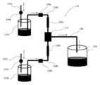
図1は、第1実施形態に係るマイクロリアクターのフローを示している。
図1に示すように、第1実施形態に係るマイクロリアクター10は、原料タンク12と、恒温槽14と、反応物タンク16を備えている。原料タンク12は、液体原料を貯留するためのタンクである。恒温槽14は、液体原料を加熱するための槽である。液体原料を加熱することによって得られた反応物は、反応物タンク16に貯留される。原料タンク12と後述する小径部28は、配管18によって接続されている。小径部28と反応物タンク16は、配管20によって接続されている。配管20を流れる液体原料は、恒温槽14内を通過することで所定の温度に加熱される。<First Embodiment>
Hereinafter, a first embodiment of the present invention will be described in detail with reference to the drawings.
FIG. 1 shows a flow of the microreactor according to the first embodiment.
As shown in FIG. 1, the
本実施形態に係るマイクロリアクター10は、液体原料を加熱して目的とする物質を得ることのできる装置である。本明細書において、液体原料とは、反応させる液体の物質を意味する。または、液体原料とは、反応させる物質を含む溶液を意味する。マイクロリアクター10は、対象である物質を反応温度にまで加熱する。マイクロリアクター10は、対象である物質を加熱して反応させることで目的物質を得ることができる。The
原料タンク12は、液体原料を貯留できるのであれば特に制限はなく、例えば、金属製、樹脂製あるいはガラス製のタンクによって構成することができる。本実施形態では、原料タンク12は、ポリエチレン製の耐圧タンクによって構成されている。原料タンク12を耐圧タンクで構成することによって、原料タンク12の内部を高圧に維持できる。The
恒温槽14は、液体原料を所定の温度にまで加熱することができるのであれば特に制限はなく、例えば市販されている公知の恒温槽によって構成することができる。The
反応物タンク16は、液体原料を加熱することによって得られた反応物を貯留できるのであれば特に制限はなく、例えば、金属製、樹脂製あるいはガラス製のタンクによって構成することができる。The
マイクロリアクター10は、図示しない窒素タンクを備えている。窒素タンクから、原料タンク12内に窒素ガス(N2ガス)を供給することができる。窒素タンクと原料タンク12は、窒素供給配管22によって接続されている。窒素供給配管22には、圧力調整弁24(レギュレータ)が設けられている。圧力調整弁24によって、原料タンク12内の窒素ガスの圧力を調整することができる。The
窒素ガスが、本発明の「気体」に対応している。窒素ガスを供給するための窒素タンク及び窒素供給配管22が、本発明の「気体供給手段」に対応している。原料タンク12内に充填されている窒素ガスの圧力を調整する圧力調整弁24が、本発明の「圧力調整手段」に対応している。圧力調整弁24によって、原料タンク12から恒温槽14に移送される液体原料の流量を調整することができる。原料タンク12に供給されるガスの圧力範囲は1kPaから200MPaであり、好ましくは10kPaから15MPaである。Nitrogen gas corresponds to the “gas” of the present invention. The nitrogen tank and the
原料タンク12内には液体原料が貯留されている。貯留されている液体原料の上方の空間には、窒素ガスが充填されている。液体原料の上方に存在する窒素ガスの圧力によって、液体原料を原料タンク12から配管18を介して恒温槽14に移送することができる。つまり、原料タンク12は、その内部に充填されている窒素ガス(気体)の圧力によって、液体原料を次の機器に移送することができる。原料タンク12及びその内部に充填されている窒素ガスが、本発明の「移送手段」に対応している。The liquid raw material is stored in the
原料タンク12と小径部28を接続する配管18は、例えば内径1.0mmのPTFE(ポリテトラフルオロエチレン)製のチューブによって構成されている。配管18には、開閉バルブ26が設けられている。開閉バルブ26は、配管18の内部を流れる液体原料のON/OFFを制御するためのバルブである。開閉バルブ26は、例えば、電磁弁によって構成されている。原料タンク12と小径部28を接続する配管18の内部の圧力は、開閉バルブ26の許容圧力を超えないことが好ましい。開閉バルブ26が電磁弁によって構成される場合、原料タンク12と小径部28を接続する配管18の内部の圧力は、1.5MPa以下であることが好ましく、0.8MPa以下であることがより好ましい。The
配管18には、小径部28が設けられている。小径部28は、その上流側及び/または下流側の配管の内径よりも小さい内径を有する。小径部28は、その上流側及び/または下流側の配管の内径よりも小さい内径を有するチューブであってもよい。小径部28の内径は、例えば、φ0.01mm~0.3mmであることが好ましい。小径部28は、例えば、内径0.2mmのPEEK(ポリエーテルエーテルケトン)製のチューブによって構成されている。配管18と小径部28は、図5に示すように、コネクタ19aによって連結されている。小径部28とその下流側の配管20は、コネクタ19bによって連結されている。The
小径部28と反応物タンク16を接続する配管20は、例えば内径1.0mmのPTFE(ポリテトラフルオロエチレン)製のチューブによって構成されている。原料タンク12に貯留されていた液体原料は、恒温槽14によって反応温度以上に加熱された後、配管20を介して反応物タンク16移送される。液体原料が加熱されることにより、液体原料に含まれる物質が反応する。反応によって得られた目的物質は、反応物タンク16内に貯留される。 The
上述のように構成された第1実施形態に係るマイクロリアクター10の作用及び効果について説明する。
従来のマイクロリアクターは、液体原料を移送するために、高価なシリンジポンプやプランジャポンプを備えていた。そのため、装置全体の製造コストが莫大になるという問題があった。
本実施形態に係るマイクロリアクター10によれば、原料タンク12に充填されている窒素ガスの圧力によって、液体原料を移送することができるため、シリンジポンプやプランジャポンプが不要である。したがって、装置全体の製造コストを大幅に削減することができる。The operation and effect of the
Conventional microreactors have been equipped with expensive syringe pumps and plunger pumps to transfer liquid raw materials. Therefore, there has been a problem that the manufacturing cost of the entire apparatus becomes enormous.
According to the
本実施形態に係るマイクロリアクター10によれば、圧力調整弁24によって原料タンク12内の窒素ガスの圧力を一定に維持できるため、配管20を流れる液体原料の流量が変動することを防止することができる。
さらに、原料タンク12と配管20を接続する配管18には、小径部28が設けられている。この小径部28によって圧力損失を調整することができる。圧力損失を調整することによって、配管18を流れる液体原料の流量を調整することができる。その結果、配管20を流れる液体原料の流量を一定に維持することができる。また、反応を均一に進行させることが可能であり、一定の品質を有する目的物を安定的に製造することができる。According to the
Furthermore, a
<第2実施形態>
以下、本発明の第2実施形態について図面を参照しながら詳細に説明する。
図2は、第2実施形態に係るマイクロリアクターのフローを示している。
図2に示すように、第2実施形態に係るマイクロリアクター110は、2つの原料タンク112a、112bと、ミキサ114と、反応物タンク116を備えている。原料タンク112a、112bは、2種類の液体原料を貯留するためのタンクである。原料タンク112a、112bから送られてくる液体原料は、ミキサ114によって混合される。液体原料を混合して得られた反応物は、反応物タンク116に貯留される。原料タンク112aとミキサ114は、配管118aによって接続されている。原料タンク112bとミキサ114は、配管118bによって接続されている。ミキサ114と反応物タンク116は、配管120によって接続されている。Second Embodiment
Hereinafter, a second embodiment of the present invention will be described in detail with reference to the drawings.
FIG. 2 shows a flow of the microreactor according to the second embodiment.
As shown in FIG. 2, the
本実施形態に係るマイクロリアクター110は、2種類の液体原料を混合することのできる装置である。2種類の液体原料を混合して反応させることによって、目的とする反応物を得ることができる。The
原料タンク112a、112bは、液体原料を貯留できるのであれば特に制限はなく、例えば、金属製、樹脂製、あるいはガラス製のタンクによって構成することができる。本実施形態では、原料タンク112a、112bは、ポリエチレン製の耐圧タンクによって構成されている。原料タンク112a、112bを耐圧タンクで構成することによって、原料タンク112a、112bの内部を高圧に維持できる。The
ミキサ114は、2種類の液体原料を混合することができるのであれば特に制限はなく、どのようなミキサを使用することもできる。ミキサ114として、例えば、市販されている公知の金属製、樹脂製、あるいはガラス製のマイクロミキサを使用することができる。マイクロミキサとは、複数の液体原料を混合するための微小流路を備えたミキサである。マイクロミキサは、例えば、金属板の一方の面に微小流路を形成し、その金属板の微小流路が形成された面にもう一枚の金属板を重ね合わせることによって製造することができる。微小流路の形状に特に制限はなく、例えば、T字型の微小流路が形成されたミキサや、Y字型の微小流路が形成されたミキサを使用することができる。微小流路の幅は特に制限されないが、例えば、幅の大きさが0.01~1000μm程度の微小流路が形成されたマイクロミキサを使用することができる。The
反応物タンク116は、液体原料を混合して得られた反応物を貯留できるのであれば特に制限はなく、例えば、金属製、樹脂製、あるいはガラス製のタンクによって構成することができる。The
マイクロリアクター110は、図示しない窒素タンクを備えている。窒素タンクから、2つの原料タンク112a、112b内に窒素ガス(N2ガス)を供給することができる。窒素タンクと原料タンク112a、112bは、窒素供給配管122a、122bによってそれぞれ接続されている。窒素供給配管122a、122bには、圧力調整弁124a、124b(レギュレータ)がそれぞれ設けられている。圧力調整弁124a、124bによって、原料タンク112a、112b内の窒素ガスの圧力をそれぞれ一定に維持することができる。また、圧力調整弁124a、124bによって、2つの原料タンク112a、112bからミキサ114に移送される液体原料の流量をそれぞれ調整することができる。原料タンク112a、112bに供給されるガスの圧力範囲は1kPaから200MPaであり、好ましくは10kPaから15MPaである。The
窒素ガスが、本発明の「気体」に対応している。窒素ガスを供給するための窒素タンク及び窒素供給配管122a、122bが、本発明の「気体供給手段」に対応している。原料タンク112a、112b内に充填されている窒素ガスの圧力を調整する圧力調整弁124a、124bが、本発明の「圧力調整手段」に対応している。Nitrogen gas corresponds to the “gas” of the present invention. The nitrogen tank and
2つの原料タンク112a、112b内には、液体原料が貯留されている。貯留されている液体原料の上方の空間には、窒素ガスがそれぞれ充填されている。液体原料の上方に存在する窒素ガスの圧力によって、液体原料を2つの原料タンク112a、112bから配管118a、118bを介してミキサ114に移送することができる。つまり、2つの原料タンク112a、112bは、その内部に充填されている窒素ガス(気体)の圧力によって、液体原料を次の機器に移送することができる。2つの原料タンク112a、112b及びその内部にそれぞれ充填されている窒素ガスが、本発明の「移送手段」に対応している。The liquid raw material is stored in the two
2つの原料タンク112a、112bとミキサ114を接続する配管118a、118bは、例えば内径1.0mmのPTFE(ポリテトラフルオロエチレン)製のチューブによって構成されている。配管118a、118bには、開閉バルブ126a、126bがそれぞれ設けられている。開閉バルブ126a、126bは、配管118a、118bの内部を流れる液体原料のON/OFFを制御するためのバルブである。開閉バルブ126a、126bは、例えば、電磁弁によって構成されている。原料タンク112a、112bと小径部128a、128bを接続する配管118a、118bの内部の圧力は、開閉バルブ126a、126bの許容圧力を超えないことが好ましい。開閉バルブ126a、126bが電磁弁によって構成される場合、原料タンク112a、112bと小径部128a、128bを接続する配管118a、118bの内部の圧力は、1.5MPa以下であることが好ましく、0.8MPa以下であることがより好ましい。The
2つの原料タンク112a、112bとミキサ114を接続する配管118a、118bには、小径部128a、128bがそれぞれ設けられている。小径部128a、128bは、その上流側及び/又は下流側の配管の内径よりも小さい内径を有するチューブであってもよい。小径部128a、128bは、例えば、内径0.2mmのPEEK(ポリエーテルエーテルケトン)製のチューブによって構成されている。配管118a、118bと小径部128a、128bは、図示しないコネクタによってそれぞれ連結されている。The
ミキサ114と反応物タンク116を接続する配管120は、例えば内径1.0mmのPTFE(ポリテトラフルオロエチレン)製のチューブによって構成されている。2つの原料タンク112a、112bに貯留されていた液体原料は、ミキサ114によって混合された後、配管120を介して反応物タンク116に移送される。これにより、2種類の液体原料に含まれる物質が反応することで得られた目的物質が、反応物タンク116内に貯留される。The
上述のように構成された第2実施形態に係るマイクロリアクター110の作用及び効果について説明する。
従来のマイクロリアクターは、液体原料を移送するために、高価なシリンジポンプやプランジャポンプを備えていた。そのため、装置全体の製造コストが莫大になるという問題があった。
本実施形態に係るマイクロリアクター110によれば、原料タンク112a、112bに充填されている窒素ガスの圧力によって、液体原料を移送することができるため、シリンジポンプやプランジャポンプが不要である。したがって、装置全体の製造コストを大幅に削減することができる。The operation and effect of the
Conventional microreactors have been equipped with expensive syringe pumps and plunger pumps to transfer liquid raw materials. Therefore, there has been a problem that the manufacturing cost of the entire apparatus becomes enormous.
According to the
本実施形態に係るマイクロリアクター110によれば、圧力調整弁124a、124bによって2つの原料タンク112a、112b内の窒素ガスの圧力を一定に維持できるため、ミキサ114に移送される液体原料の流量が変動することを防止することができる。
さらに、2つの原料タンク112a、112bとミキサ114を接続する配管118a、118bには、小径部128a、128bがそれぞれ設けられている。この小径部128a、128bによって、圧力損失を調整することができる。圧力損失を調整することによって、配管118a、118bを流れる液体原料の流量を調整することができる。また、液体原料が原料タンク112a、112bに逆流することを防止することができる。その結果、ミキサ114に供給される液体原料の流量を一定に調整することができる。また、反応を均一に進行させることが可能であり、一定の品質を有する目的物を安定的に製造することができる。According to the
Furthermore, small-
さらに、本実施形態に係るマイクロリアクター110によれば、2つの原料タンク112a、112bからミキサ114に移送される液体原料の流量比を一定に制御することができる。例えば、2つの原料タンク112a、112bに封入されている窒素ガスの圧力に差が生じた場合、圧力の高い原料タンクから、圧力の低い原料タンクへの逆流が起きやすくなる。本実施形態に係るマイクロリアクター110によれば、小径部128a、128bにおいて圧力損失が調整されるため、液体原料の流量が小さくなる。これにより、液体原料の逆流が防止されるため、ミキサ114に供給される2種類の液体原料の流量比が一定に維持される。Furthermore, according to the
このように、本実施形態に係るマイクロリアクター110によれば、原料タンクとミキサを接続する配管118a、118bに小径部128a、128bがそれぞれ設けられているため、ミキサ114に供給される2種類の液体原料の流量比が一定に維持される。As described above, according to the
本実施形態に係るマイクロリアクター110は、原料タンク内のガス圧によって液体原料を移送することができる。また、本実施形態に係るマイクロリアクター110は、小径部128a、128bを備えているため、ガス圧によって液体原料を安定的に移送することができる。本実施形態に係るマイクロリアクター110は、これらのことを実現できた点が極めて斬新であり、画期的な発明である。The
<第3実施形態>
以下、本発明の第3実施形態について図面を参照しながら詳細に説明する。
第3実施形態は、上記で説明した第2実施形態とほぼ同様であるが、3種類の液体原料を2段階で反応させる点が異なっている。以下、第2実施形態と同様の部分については説明を省略することがある。<Third Embodiment>
Hereinafter, a third embodiment of the present invention will be described in detail with reference to the drawings.
The third embodiment is substantially the same as the second embodiment described above, except that three types of liquid raw materials are reacted in two stages. Hereinafter, description of the same parts as those of the second embodiment may be omitted.
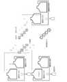
図3は、本発明の第3実施形態に係るマイクロリアクターのフローを示している。
図3に示すように、本実施形態に係るマイクロリアクター210は、3つの原料タンク212a、212b、212cと、2つのミキサ214a、214bと、反応物タンク216を備えている。原料タンク212a、212b、212cは、3種類の液体原料を貯留するためのタンクである。原料タンク212a、212b、212cから送られてくる液体原料は、2つのミキサ214a、214bによって混合される。3種類の液体原料を混合して得られた反応物は、反応物タンク216に貯留される。原料タンク212aとミキサ214aは、配管218aによって接続されている。原料タンク212bとミキサ214aは、配管218bによって接続されている。原料タンク212cとミキサ214bは、配管218cによって接続されている。ミキサ214aとミキサ214bは、配管218dによって接続されている。ミキサ214bと反応物タンク216は、配管220によって接続されている。FIG. 3 shows a flow of the microreactor according to the third embodiment of the present invention.
As shown in FIG. 3, the
本実施形態に係るマイクロリアクター210は、3種類の液体原料を2段階で混合することのできる装置である。
最初に、第1の原料タンク212aから送られてくる液体原料と、第2の原料タンク212bから送られてくる液体原料を、第1のミキサ214aによって混合する。次に、第1のミキサ214aによって混合された2種類の液体原料と、第3の原料タンク212cから送られてくる液体原料を、第2のミキサ214bによって混合する。これにより、3種類の液体原料を、2段階で混合して反応させることができる。The
First, the liquid raw material sent from the first
マイクロリアクター210は、図示しない窒素タンクを備えている。窒素タンクから、3つの原料タンク212a、212b、212c内に窒素ガス(N2ガス)を供給することができる。窒素タンクと原料タンク212a、212b、212cは、窒素供給配管222a、222b、222cによってそれぞれ接続されている。窒素供給配管222a、222b、222cには、圧力調整弁224a、224b、224c(レギュレータ)がそれぞれ設けられている。圧力調整弁224a、224b、224cによって、原料タンク212a、212b、212c内の窒素ガスの圧力をそれぞれ一定に維持することができる。また、圧力調整弁224a、224b、224cによって、3つの原料タンク212a、212b、212cからミキサ214a、214bに移送される液体原料の流量をそれぞれ調整することができる。原料タンク212a、212b、212cに供給されるガスの圧力範囲は1kPaから200MPaであり、好ましくは10kPaから15MPaである。The
窒素ガスが、本発明の「気体」に対応している。窒素ガスを供給するための窒素タンク及び窒素供給配管222a、222b、222cが、本発明の「気体供給手段」に対応している。原料タンク212a、212b、212c内に充填されている窒素ガスの圧力を調整する圧力調整弁224a、224b、224cが、本発明の「圧力調整手段」に対応している。Nitrogen gas corresponds to the “gas” of the present invention. Nitrogen tanks and
3つの原料タンク212a、212b、212c内には、液体原料が貯留されている。貯留されている液体原料の上方の空間には、窒素ガスがそれぞれ充填されている。液体原料の上方に存在する窒素ガスの圧力によって、液体原料を次の機器に移送することができる。すなわち、第1の原料タンク212aに貯留されている液体原料を、第1のミキサ214aに移送することができる。第2の原料タンク212bに貯留されている液体原料を、第1のミキサ214aに移送することができる。第3の原料タンク212cに貯留されている液体原料を、第2のミキサ214bに移送することができる。3つの原料タンク212a、212b、212c及びその内部にそれぞれ充填されている窒素ガスが、本発明の「移送手段」に対応している。Liquid raw materials are stored in the three
原料タンクとミキサを接続する配管218a、218b、218cは、例えば内径1.0mmのPTFE(ポリテトラフルオロエチレン)製のチューブによって構成されている。配管218a、218b、218cには、開閉バルブ226a、226b、226cがそれぞれ設けられている。開閉バルブ226a、226b、226cは、配管218a、218b、218cの内部を流れる液体原料のON/OFFを制御するためのバルブである。開閉バルブ226a、226b、226cは、例えば、電磁弁によって構成されている。原料タンク212a、212b、212cと小径部228a、228b、228cを接続する配管218a、218b、218cの内部の圧力は、開閉バルブ226a、226b、226cの許容圧力を超えないことが好ましい。開閉バルブ226a、226b、226cが電磁弁によって構成される場合、原料タンク212a、212b、212cと小径部228a、228b、228cを接続する配管218a、218b、218cの内部の圧力は、1.5MPa以下であることが好ましく、0.8MPa以下であることがより好ましい。The
原料タンクとミキサを接続する配管218a、218b、218cには、小径部228a、228b、228cがそれぞれ設けられている。小径部228a、228b、228cは、その上流側及び/又は下流側の配管の内径よりも小さい内径を有するチューブであってもよい。小径部228a、228b、228cは、例えば、内径0.2mmのPEEK(ポリエーテルエーテルケトン)製のチューブによって構成されている。配管218a、218b、218cと小径部228a、228b、228cは、図示しないコネクタによってそれぞれ連結されている。The
ミキサ214bと反応物タンク216を接続する配管220は、例えば内径1.0mmのPTFE(ポリテトラフルオロエチレン)製のチューブによって構成されている。3つの原料タンク212a、212b、212cに貯留されていた液体原料は、ミキサ214a、214bによって2段階で混合された後、配管220を介して反応物タンク216に移送される。これにより、3種類の液体原料に含まれる物質が反応することで得られた目的物質が、反応物タンク216内に貯留される。 The
上述のように構成された第3実施形態に係るマイクロリアクター210の作用及び効果について説明する。
従来のマイクロリアクターは、液体原料を移送するために、高価なシリンジポンプやプランジャポンプを備えていた。そのため、装置全体の製造コストが莫大になるという問題があった。
本実施形態に係るマイクロリアクター210によれば、原料タンク212a、212b、212cに充填されている窒素ガスの圧力によって、液体原料を移送することができるため、シリンジポンプやプランジャポンプが不要である。したがって、装置全体の製造コストを大幅に削減することができる。Operations and effects of the
Conventional microreactors have been equipped with expensive syringe pumps and plunger pumps to transfer liquid raw materials. Therefore, there has been a problem that the manufacturing cost of the entire apparatus becomes enormous.
According to the
本実施形態に係るマイクロリアクター210によれば、圧力調整弁224a、224b、224cによって3つの原料タンク212a、212b、212c内の窒素ガスの圧力を一定に維持できるため、ミキサ214a、214bに移送される液体原料の流量が変動することを防止することができる。
さらに、原料タンク212a、212b、212cとミキサ214a、214bを接続する配管218a、218b、218cには、小径部228a、228b、228cがそれぞれ設けられている。この小径部228a、228b、228cによって、圧力損失を調整することができる。圧力損失を調整することによって、配管218a、218b、218cを流れる液体原料の流量を調整することができる。また、液体原料が原料タンク212a、212b、212cに逆流することを防止することができる。その結果、ミキサ214a、214bに供給される液体原料の流量を一定に調整することができる。また、反応を均一に進行させることが可能であり、一定の品質を有する目的物を安定的に製造することができる。According to the
Further, small-
さらに、本実施形態に係るマイクロリアクター210によれば、2つの原料タンク212a、212bからミキサ214aに移送される液体原料の流量比を一定に制御することができる。例えば、2つの原料タンク212a、212bに封入されている窒素ガスの圧力に差が生じた場合、圧力の高い原料タンクから、圧力の低い原料タンクへの逆流が起きやすくなる。本実施形態に係るマイクロリアクター210によれば、小径部228a、228bにおいて圧力損失が調整されるため、液体原料の流量が小さくなる。これにより、液体原料の逆流が防止されるため、ミキサ214aに供給される2種類の液体原料の流量比が一定に維持される。同様に、第2のミキサ214bにおいても、原料タンク212c及びミキサ214aから移送される液体原料の流量比が一定に維持される。Furthermore, according to the
このように、本実施形態に係るマイクロリアクター210によれば、原料タンクとミキサを接続する配管218a、218b、218cに小径部228a、228b、228cがそれぞれ設けられているため、ミキサ214a、214bに供給される3種類の液体原料の流量比が一定に維持される。As described above, according to the
本実施形態に係るマイクロリアクター210は、原料タンク内のガス圧によって液体原料を移送することができる。また、本実施形態に係るマイクロリアクター210は、小径部228a、228b、228cを備えているため、ガス圧によって液体原料を安定的に移送することができる。本実施形態に係るマイクロリアクター210は、これらのことを実現できた点が極めて斬新であり、画期的な発明である。The
<第4実施形態>
以下、本発明の第4実施形態について図面を参照しながら詳細に説明する。
第4実施形態は、上記で説明した第2実施形態とほぼ同様であるが、2種類の液体原料を混合するのではなく、液体原料と気体原料を混合する点が異なっている。以下、第2実施形態と同様の部分については説明を省略することがある。<Fourth embodiment>
Hereinafter, the fourth embodiment of the present invention will be described in detail with reference to the drawings.
The fourth embodiment is substantially the same as the second embodiment described above, but differs in that the liquid raw material and the gas raw material are mixed instead of mixing the two kinds of liquid raw materials. Hereinafter, description of the same parts as those of the second embodiment may be omitted.
図4は、本発明の第4実施形態に係るマイクロリアクターのフローを示している。
図4に示すように、本実施形態に係るマイクロリアクター310は、原料タンク312と、原料タンク313と、ミキサ314と、反応物タンク316を備えている。原料タンク312は、液体原料を貯留するためのタンクである。原料タンク313は、気体原料を貯留するためのタンクである。液体原料と気体原料は、ミキサ314によって混合される。液体原料と気体原料を混合して得られた反応物は、反応物タンク316に貯留される。原料タンク312とミキサ314は、配管318aによって接続されている。原料タンク313とミキサ314は、配管318bによって接続されている。ミキサ314と反応物タンク316は、配管320によって接続されている。FIG. 4 shows a flow of the microreactor according to the fourth embodiment of the present invention.
As shown in FIG. 4, the
本実施形態に係るマイクロリアクター310は、液体原料と気体原料を混合して反応物を得ることのできる装置である。The
マイクロリアクター310は、図示しない窒素タンクを備えている。窒素タンクから、原料タンク312内に窒素ガス(N2ガス)を供給することができる。窒素タンクと原料タンク312は、窒素供給配管322によって接続されている。窒素供給配管322には、圧力調整弁324(レギュレータ)が設けられている。圧力調整弁324によって、原料タンク312内の窒素ガスの圧力を一定に維持することができる。また、圧力調整弁324によって、原料タンク312からミキサ314に移送される液体原料の流量を調整することができる。原料タンク312に供給されるガスの圧力範囲は1kPaから200MPaであり、好ましくは10kPaから15MPaである。The
窒素ガスが、本発明の「気体」に対応している。窒素ガスを供給するための窒素タンク及び窒素供給配管322が、本発明の「気体供給手段」に対応している。原料タンク312内に充填されている窒素ガスの圧力を調整する圧力調整弁324が、本発明の「圧力調整手段」に対応している。Nitrogen gas corresponds to the “gas” of the present invention. The nitrogen tank and
原料タンク312内には、液体原料が貯留されている。貯留されている液体原料の上方の空間には、窒素ガスが充填されている。液体原料の上方に存在する窒素ガスの圧力によって、原料タンク312に貯留されている液体原料を、ミキサ314に移送することができる。原料タンク312及びその内部に充填されている窒素ガスが、本発明の「移送手段」に対応している。Liquid raw material is stored in the
原料タンク312とミキサ314を接続する配管318aには、小径部328が設けられている。小径部328は、その上流側及び/又は下流側の配管の内径よりも小さい内径を有するチューブであってもよい。小径部328は、例えば、内径0.2mmのPEEK(ポリエーテルエーテルケトン)製のチューブによって構成されている。配管318aと小径部328は、図示しないコネクタによって連結されている。A small-
原料タンク313とミキサ314を接続する配管318bには、圧力調整弁325(レギュレータ)が設けられている。圧力調整弁325によって、原料タンク313からミキサ314に供給される気体原料の圧力を調整することが可能である。また、圧力調整弁325によって、ミキサ314に供給される気体原料の流量を一定に維持することができる。A pressure adjustment valve 325 (regulator) is provided in the
第4の実施形態に係るマイクロリアクター310によれば、第2の実施形態に係るマイクロリアクター110と同様の作用効果を得ることができる。
本発明のマイクロリアクターは、2種類の液体原料を混合する反応系だけでなく、液体原料と気体原料を混合する反応系に適用することも可能である。According to the
The microreactor of the present invention can be applied not only to a reaction system that mixes two types of liquid materials, but also to a reaction system that mixes liquid materials and gas materials.
<その他の実施形態>
(1)上記実施形態では、原料タンクの数が1つ、2つ、または3つである例を示したが、原料タンクの数はこれらに限定されない。
(2)上記実施形態では、配管の材質が樹脂である例を示したが、配管の材質はこれに限定されない。配管は、例えば金属によって形成されてもよい。
(3)上記実施形態では、小径部は、樹脂製のチューブの例を示したが、小径部はこれに限定されない。小径部は、例えば、金属のチューブによって形成されてもよい。また、HPLCやイオンクロマトの背圧を調整するために使用されている公知のバックプレッシャーチューブやバックプレッシャーレギュレーターを、小径部として使用してもよい。
(4)上記実施形態では、液体原料を移送するための気体が窒素である例を示したが、気体の種類はこれに限定されない。液体原料を移送するための気体は、例えば、空気やアルゴンガスであってもよい。
(5)上記実施形態では、反応させる物質(液体原料及び/又は原料の溶液)を移送する例を示したが、原料の希釈用溶剤、反応停止剤、あるいは抽出用溶剤等を移送してもよい。<Other embodiments>
(1) In the above embodiment, an example in which the number of raw material tanks is one, two, or three is shown, but the number of raw material tanks is not limited thereto.
(2) In the above embodiment, an example in which the material of the pipe is resin is shown, but the material of the pipe is not limited to this. The pipe may be formed of metal, for example.
(3) In the said embodiment, although the small diameter part showed the example of resin-made tubes, a small diameter part is not limited to this. The small diameter portion may be formed by, for example, a metal tube. Moreover, you may use the well-known back pressure tube and back pressure regulator currently used in order to adjust the back pressure of HPLC or ion chromatography as a small diameter part.
(4) In the said embodiment, although the gas for transferring a liquid raw material showed the example which is nitrogen, the kind of gas is not limited to this. The gas for transferring the liquid raw material may be, for example, air or argon gas.
(5) In the above embodiment, an example of transferring a substance to be reacted (liquid raw material and / or raw material solution) has been shown. However, even if a raw material dilution solvent, a reaction terminator, or an extraction solvent is transferred. Good.
上記実施形態では、原料タンクと小径部が1本の配管によって接続されている例を示したが、原料タンクに接続されている配管が2本以上に分岐してもよい。すなわち、原料タンクから複数の配管が分岐しており、その分岐した配管のそれぞれに小径部が接続されてもよい。In the above embodiment, an example is shown in which the raw material tank and the small-diameter portion are connected by a single pipe, but the pipe connected to the raw material tank may be branched into two or more. That is, a plurality of pipes may be branched from the raw material tank, and a small diameter portion may be connected to each of the branched pipes.
小径部は、その上流側及び/又は下流側の配管の内径よりも小さい内径を有する。好ましくは、小径部は、その上流側及び下流側の配管の内径よりも小さい内径を有する。以下、小径部について更に詳細に説明する。The small diameter portion has an inner diameter that is smaller than the inner diameter of the upstream and / or downstream piping. Preferably, the small diameter portion has an inner diameter smaller than the inner diameters of the upstream and downstream pipes. Hereinafter, the small diameter portion will be described in more detail.
小径部は、バルブで構成してもよい。例えば、流路の大きさを調整することのできる弁体やスプールを備えたバルブを、小径部として使用することができる。例えば、ゲートバルブやグローブバルブを、小径部として使用することができる。例えば、流路の大きさを調整することのできる「2-wayバルブ」(ジーエルサイエンス株式会社製)を、小径部として使用することができる。The small diameter part may be constituted by a valve. For example, a valve provided with a valve body and a spool capable of adjusting the size of the flow path can be used as the small diameter portion. For example, a gate valve or a globe valve can be used as the small diameter portion. For example, a “2-way valve” (manufactured by GL Science Co., Ltd.) that can adjust the size of the flow path can be used as the small diameter portion.
小径部は、オリフィスで構成してもよい。例えば、薄い樹脂製あるいは金属製のプレートに、上流側及び下流側の配管の内径よりも小さい開口が形成されたオリフィスを、小径部として使用することができる。オリフィスは、1枚のプレートに1つの開口が形成されたものでもよく、1枚のプレートに複数の開口が形成されたものでもよい。例えば、HPLCやイオンクロマトグラフィー用インラインフィルタを、小径部として使用することができる。例えば、HPLC用PEEK製プレカラムフィルター(株式会社島津ジーエルシー製)を、小径部として使用することができる。The small diameter part may be constituted by an orifice. For example, an orifice in which an opening smaller than the inner diameter of the upstream and downstream pipes is formed in a thin resin or metal plate can be used as the small diameter portion. The orifice may be one in which one opening is formed in one plate, or one in which a plurality of openings are formed in one plate. For example, an in-line filter for HPLC or ion chromatography can be used as the small diameter portion. For example, a pre-column filter made of PEEK for HPLC (manufactured by Shimadzu GL Corporation) can be used as the small diameter portion.
図6に示すように、小径部400は、金属板402aの一方の面に微小流路404を形成し、その金属板402aの微小流路404が形成された面にもう一枚の金属板402bを重ね合わせることによって製造することができる。すなわち、小径部400は、上述のマイクロミキサと同様に、金属板402aに微小流路404を形成したものであってもよい。微小流路404は、小径部400の上流側の配管406及び下流側の配管408の内径よりも小さい内径を有する。As shown in FIG. 6, the small-
図7に示すように、小径部410は、金属製あるいは樹脂製のチューブ412を物理的に変形させて、そのチューブ412の内径を部分的に小さくしたものであってもよい。チューブ412の変形した部分の内径414は、その上流側及び/又は下流側の配管の内径よりも小さい内径を有する。As shown in FIG. 7, the small-
以下、本発明をさらに具体化した実施例について説明する。Hereinafter, examples that further embody the present invention will be described.
(実施例1)
実施形態1で説明したマイクロリアクター10を、以下の式(1)に示すDiels―Alder反応に適用した。Example 1
The

無水マレイン酸(A)9.8g(10mmol)と1,3―シクロヘキサジエン(B)8.0g(10mmol)を、トルエン100mlに溶解させることで液体原料を得た。得られた液体原料を、原料タンクに貯留した。A liquid raw material was obtained by dissolving 9.8 g (10 mmol) of maleic anhydride (A) and 8.0 g (10 mmol) of 1,3-cyclohexadiene (B) in 100 ml of toluene. The obtained liquid raw material was stored in the raw material tank.
原料タンクに貯留されている液体原料を、原料タンク内に充填されている窒素ガスの圧力によって、恒温槽に移送した。このとき、原料タンク内の窒素ガスの圧力は、0.02MPaに調整した。原料タンクと恒温槽を通る配管には、小径部として、内径0.2mm、長さ15cmのチューブを取り付けた。恒温槽を通る配管は、内径1.0mmであり、長さ4mである。恒温槽の設定温度は、80℃である。The liquid raw material stored in the raw material tank was transferred to a constant temperature bath by the pressure of nitrogen gas filled in the raw material tank. At this time, the pressure of the nitrogen gas in the raw material tank was adjusted to 0.02 MPa. A tube having an inner diameter of 0.2 mm and a length of 15 cm was attached to the pipe passing through the raw material tank and the thermostat as a small diameter portion. The pipe passing through the thermostat has an inner diameter of 1.0 mm and a length of 4 m. The set temperature of the thermostatic bath is 80 ° C.
液体原料を恒温槽に一定の流速で移送することによって、Diels―Alder付加体(C)を定量的に得ることができた。Diels-Alder adduct (C) could be obtained quantitatively by transferring the liquid raw material to the thermostatic chamber at a constant flow rate.
(実施例2)
実施形態2で説明したマイクロリアクター110を、以下の式(2)に示すカルバゾールの臭素化反応に適用した。(Example 2)
The

カルバゾール(D)25g(0.15mol)をDMFに溶解させることで液体原料250mlを得た。得られた液体原料を、第1の原料タンクに貯留した。250 ml of liquid raw material was obtained by dissolving 25 g (0.15 mol) of carbazole (D) in DMF. The obtained liquid raw material was stored in the first raw material tank.
N-ブロモスクシイミド(NBS)26.6g(0.15mol)をDMFに溶解させることで液体原料250mlを得た。得られた液体原料を、第2の原料タンクに貯留した。By dissolving 26.6 g (0.15 mol) of N-bromosuccinimide (NBS) in DMF, 250 ml of a liquid raw material was obtained. The obtained liquid raw material was stored in the second raw material tank.
原料タンクに貯留されている液体原料を、原料タンク内に充填されている窒素ガスの圧力によって、ミキサに移送した。このとき、第1の原料タンク内の窒素ガスの圧力を、0.14MPaに調整した。第2の原料タンク内の窒素ガスの圧力を、0.03MPaに調整した。The liquid raw material stored in the raw material tank was transferred to the mixer by the pressure of the nitrogen gas filled in the raw material tank. At this time, the pressure of the nitrogen gas in the first raw material tank was adjusted to 0.14 MPa. The pressure of nitrogen gas in the second raw material tank was adjusted to 0.03 MPa.
内径1.0mmのT字型の微小流路が形成されたミキサ(YMC社製 YMC-P-0020)を用いて、2種類の液体原料を混合した。第1の原料タンクとミキサを接続する配管には、小径部として、内径0.2mm、長さ5cmのチューブを取り付けた。Two types of liquid raw materials were mixed using a mixer (YMC-P-0020, manufactured by YMC) in which a T-shaped microchannel with an inner diameter of 1.0 mm was formed. A tube having an inner diameter of 0.2 mm and a length of 5 cm was attached as a small diameter portion to the pipe connecting the first raw material tank and the mixer.
ミキサと反応物タンクは、その周囲が-5℃に冷却された内径1.0mm、長さ1mの配管によって接続されている。ミキサによって混合された2種類の液体原料をこの配管に流すことによって、臭素化反応が進行し、ブロモカルバゾール(E)が80%の反応転化率で得られた。このとき、ジブロモ体(F)が、7%生成した。The mixer and the reactant tank are connected by a pipe with an inner diameter of 1.0 mm and a length of 1 m, the periphery of which is cooled to −5 ° C. By flowing two kinds of liquid raw materials mixed by the mixer through this pipe, bromination reaction proceeded, and bromocarbazole (E) was obtained at a reaction conversion rate of 80%. At this time, 7% of dibromo compound (F) was produced.
(実施例3)
実施形態2で説明したマイクロリアクター110を、以下の式(3)に示すスチレンスルホン酸ナトリウム(PSSNa)(H)の合成反応に適用した。(Example 3)
The

スチレンスルホン酸ナトリウムモノマー(G)50gを水に溶解させることで液体原料250mlを得た。得られた液体原料を、第1の原料タンクに貯留した。250 ml of liquid raw material was obtained by dissolving 50 g of sodium styrenesulfonate monomer (G) in water. The obtained liquid raw material was stored in the first raw material tank.
過硫酸ナトリウム0.5gを水に溶解させることで液体原料250mlを得た。得られた液体原料を、第2の原料タンクに貯留した。250 ml of liquid raw material was obtained by dissolving 0.5 g of sodium persulfate in water. The obtained liquid raw material was stored in the second raw material tank.
原料タンクに貯留されている液体原料を、原料タンク内に充填されている窒素ガスの圧力によって、ミキサに移送した。このとき、第1の原料タンク内の窒素ガスの圧力を、0.03MPaに調整した。第2の原料タンク内の窒素ガスの圧力を、0.03MPaに調整した。The liquid raw material stored in the raw material tank was transferred to the mixer by the pressure of the nitrogen gas filled in the raw material tank. At this time, the pressure of the nitrogen gas in the first raw material tank was adjusted to 0.03 MPa. The pressure of nitrogen gas in the second raw material tank was adjusted to 0.03 MPa.
内径1.0mmのT字型の微小流路が形成されたミキサ(YMC社製 YMC-P-0020)を用いて、2種類の液体原料を混合した。2つの原料タンクとミキサを接続する配管には、小径部として、内径0.2mm、長さ10cmのチューブをそれぞれ取り付けた。Two types of liquid raw materials were mixed using a mixer (YMC-P-0020, manufactured by YMC) in which a T-shaped microchannel with an inner diameter of 1.0 mm was formed. Tubes having an inner diameter of 0.2 mm and a length of 10 cm were attached to the pipes connecting the two raw material tanks and the mixer, respectively, as small diameter portions.
ミキサと反応物タンクは、その周囲が80℃に加熱された内径1.0mm、長さ10mの配管によって接続されている。ミキサによって混合された2種類の液体原料をこの配管に流すことによって、ポリスチレンスルホン酸ナトリウム(H)(Mn:83191, Mw:148234, Mw/Mn:1.78)が反応物として得られた。The mixer and the reactant tank are connected by a pipe having an inner diameter of 1.0 mm and a length of 10 m, the periphery of which is heated to 80 ° C. By flowing two kinds of liquid raw materials mixed by the mixer through this pipe, sodium polystyrene sulfonate (H) (Mn: 83191, Mw: 148234, Mw / Mn: 1.78) was obtained as a reactant.
マイクロリアクターの運転を18時間連続して行ったが、液体原料を安定的に移送することができた。また、反応物を安定的に製造することができた。The microreactor was operated continuously for 18 hours, but the liquid raw material could be stably transferred. In addition, the reaction product could be stably produced.
(実施例4)
実施形態3で説明したマイクロリアクター210を、以下の式(4)に示すナフチルボロン酸の合成反応に適用した。Example 4
The

1-ブロモナフタレン(I)6.3gをTHFに溶解させることで液体原料100ml(0.31M)を得た。得られた液体原料を、第1の原料タンクに貯留した。100 ml (0.31 M) of liquid raw material was obtained by dissolving 6.3 g of 1-bromonaphthalene (I) in THF. The obtained liquid raw material was stored in the first raw material tank.
1.6M n-BuLi ヘキサン溶液25mlをシクロペンチルメチルエーテル(CPME)75mlで希釈することで液体原料100ml(0.4M)を得た。得られた液体原料を、第2の原料タンクに貯留した。A liquid raw material of 100 ml (0.4 M) was obtained by diluting 25 ml of 1.6 M n-BuLi-hexane solution with 75 ml of cyclopentyl methyl ether (CPME). The obtained liquid raw material was stored in the second raw material tank.
ホウ酸トリイソプロピル(B(OiPr)3)11.6gをTHFに溶解させることで液体原料100ml(0.62M)を得た。得られた液体原料を、第3の原料タンクに貯留した。11.6 g of triisopropyl borate (B (OiPr)3 ) was dissolved in THF to obtain 100 ml (0.62M) of a liquid raw material. The obtained liquid raw material was stored in the third raw material tank.
第1及び第2の原料タンクに貯留されている液体原料を、原料タンク内に充填されている窒素ガスの圧力によって、第1のミキサに移送した。このとき、第1の原料タンク内の窒素ガスの圧力を、0.07MPaに調整した。第2の原料タンク内の窒素ガスの圧力を、0.07MPaに調整した。2種類の液体原料を第1のミキサによって室温で混合し、内径1.0mm、長さ20cmの配管内でLi化させた。The liquid raw material stored in the first and second raw material tanks was transferred to the first mixer by the pressure of nitrogen gas filled in the raw material tank. At this time, the pressure of the nitrogen gas in the first raw material tank was adjusted to 0.07 MPa. The pressure of nitrogen gas in the second raw material tank was adjusted to 0.07 MPa. Two types of liquid raw materials were mixed by a first mixer at room temperature, and Li was formed in a pipe having an inner diameter of 1.0 mm and a length of 20 cm.
第3の原料タンクに貯留されている液体原料を、原料タンク内に充填されている窒素ガスの圧力によって、第2のミキサに移送した。このとき、第3の原料タンク内の窒素ガスの圧力を、0.07MPaに調整した。The liquid raw material stored in the third raw material tank was transferred to the second mixer by the pressure of nitrogen gas filled in the raw material tank. At this time, the pressure of the nitrogen gas in the third raw material tank was adjusted to 0.07 MPa.
内径1.0mmのT字型の微小流路が形成されたミキサ(YMC社製 YMC-P-0020)を用いて、液体原料を混合した。原料タンクとミキサを接続する配管には、小径部として、内径0.2mm、長さ5cmのチューブをそれぞれ取り付けた。The liquid raw material was mixed using a mixer (YMC-P-0020, manufactured by YMC) in which a T-shaped microchannel with an inner diameter of 1.0 mm was formed. Tubes with an inner diameter of 0.2 mm and a length of 5 cm were attached to the pipes connecting the raw material tank and the mixer as small diameter portions.
第1のミキサによって混合された2種類の液体原料と、第3の原料タンクに貯留されている液体原料を、第2のミキサによって混合し、内径1mm、長さ100cmの配管内で反応させた。これにより、目的とする反応物である1-ナフチルボロン酸(K)を得た。The two kinds of liquid raw materials mixed by the first mixer and the liquid raw material stored in the third raw material tank were mixed by the second mixer and reacted in a pipe having an inner diameter of 1 mm and a length of 100 cm. . As a result, 1-naphthylboronic acid (K), which was the target reactant, was obtained.
得られた反応物をHPLCで分析した結果は、1-ナフチルボロン酸(K)92%、1-ブロモナフタレン(I)0.4%、脱ブロモ体であるナフタレン(L)4%であった。高温条件で生成しやすいブチル付加体(M)の生成は確認されなかった。As a result of analyzing the obtained reaction product by HPLC, it was found that 92% of 1-naphthylboronic acid (K), 0.4% of 1-bromonaphthalene (I), and 4% of naphthalene (L) as a debromo form were obtained. . Formation of a butyl adduct (M) that was easily generated under high temperature conditions was not confirmed.
(実施例5)
原料タンクを2つ用いて、図8に示す装置を組み立てた。この装置を用いて、3流路のナンバリングアップについて検討した。
図8に示すように、共通の窒素ガス供給源から、原料タンクAと原料タンクBに窒素ガスを供給した。窒素ガス供給源の出口側の配管に、圧力調整弁(レギュレータ)を取り付けた。圧力調整弁の先を分岐させて、その分岐させた先にコック及び原料タンクをそれぞれ接続した。(Example 5)
The apparatus shown in FIG. 8 was assembled using two raw material tanks. Using this device, the numbering up of three channels was examined.
As shown in FIG. 8, nitrogen gas was supplied to the raw material tank A and the raw material tank B from a common nitrogen gas supply source. A pressure regulating valve (regulator) was attached to the piping on the outlet side of the nitrogen gas supply source. The tip of the pressure regulating valve was branched, and a cock and a raw material tank were connected to the branched tip.
原料タンクAには、1/8インチ、内径1.58mm、長さ1300mm(800mmと500mmのチューブを接続したチューブ)の PTFE製チューブを2本接続した。これらのチューブを、流路A1、流路A2と呼ぶ。
原料タンクBには、上記と同じPTFE製チューブを1本接続した。このチューブを、流路Bと呼ぶ。
それぞれのチューブの先に、三方バルブ、ドレイン、及び、1/16インチ、内径1mm、長さ300mmのPTFE製チューブを接続した。そのチューブの先に、1/16インチ、内径0.25mm、長さ80mmのPEEK製チューブを接続した。このPEEK製のチューブは、本発明の小径部に相当する。その小径部の先に、反応物タンクを接続した。To the raw material tank A, two PTFE tubes of 1/8 inch, an inner diameter of 1.58 mm, and a length of 1300 mm (a tube in which 800 mm and 500 mm tubes are connected) were connected. These tubes are referred to as flow path A1 and flow path A2.
The same PTFE tube as above was connected to the raw material tank B. This tube is referred to as a flow path B.
A three-way valve, a drain, and a 1/16 inch, 1 mm inner diameter, 300 mm long PTFE tube were connected to the tip of each tube. A PEEK tube of 1/16 inch, an inner diameter of 0.25 mm, and a length of 80 mm was connected to the tip of the tube. This PEEK tube corresponds to the small diameter portion of the present invention. A reactant tank was connected to the tip of the small diameter portion.
各原料タンクに、水を入れた。原料タンクに供給するガスの圧力を、50kPaに設定した。流路A1のバルブを開放してから30秒後に、流路A2のバルブを開放した。流路A2のバルブを開放してから30秒後に、流路Bのバルブを開放した。バルブを開放してから10分後に、それぞれのバルブを閉めた。バルブを閉めた後、反応物タンクの重量を計測した。計測された反応物タンクの重量から、各流路の流速を求めた。このような手順により、流速を3回測定した。測定結果を、以下の表1に示す。水 Water was put into each raw material tank. The pressure of the gas supplied to the raw material tank was set to 50 kPa. 30 seconds after opening the valve of the flow path A1, the valve of the flow path A2 was opened. 30 seconds after opening the valve of the flow path A2, the valve of the flow path B was opened. Each valve was closed 10 minutes after opening the valve. After closing the valve, the weight of the reactant tank was measured. From the measured weight of the reactant tank, the flow rate of each flow path was determined. According to such a procedure, the flow rate was measured three times. The measurement results are shown in Table 1 below.

3本の流路の流速を比較すると、ばらつきの指標となるRSD(相対標準偏差)は0.5%程度であり、流速のばらつきは小さかった。このように、本発明のマイクロリアクターによれば、原料タンクからほぼ均等に複数の流路に液体を流すことができる。When comparing the flow rates of the three channels, the RSD (relative standard deviation), which is an indicator of variation, was about 0.5%, and the variation in flow rate was small. As described above, according to the microreactor of the present invention, it is possible to flow the liquid from the raw material tank into the plurality of flow paths almost evenly.
本発明のマイクロリアクターによれば、装置の並列化によるナンバリングアップが可能であるとともに、1つの原料タンクに複数の流路を接続することによってナンバリングアップが可能である。According to the microreactor of the present invention, the numbering can be increased by paralleling the devices, and the numbering can be increased by connecting a plurality of flow paths to one raw material tank.
原料タンクAには2本の流路が接続しており、原料タンクBには1本の流路が接続している。原料タンクAと原料タンクBに接続する流路の数が異なるにもかかわらず、それぞれの流路の流速は同じである。本発明のマイクロリアクターによって、複数の流路にほぼ均等に液体を流せることがわかる。このような特徴的な効果は、小径部を使用することによって得られる。これに対して、従来のシリンジポンプやプランジャポンプを使用した場合、流路A1と流路A2の流速は、流路Bの約半分になる。Two channels are connected to the raw material tank A, and one channel is connected to the raw material tank B. Despite the difference in the number of flow paths connected to the raw material tank A and the raw material tank B, the flow rates of the respective flow paths are the same. It can be seen that the microreactor of the present invention allows the liquid to flow through the plurality of channels almost evenly. Such a characteristic effect is obtained by using a small diameter portion. On the other hand, when a conventional syringe pump or plunger pump is used, the flow rates of the flow paths A1 and A2 are about half that of the flow path B.
(実施例6)
1つの原料タンクに10本の流路を接続して、図9に示す装置を組み立てた。この装置を用いて、10流路のナンバリングアップについて検討した。
図9に示すように、窒素ガス供給源から、原料タンクに高圧の窒素ガスを供給した。この原料タンクに、1/8インチ、内径1.58mm、長さ1300mm(800mmと500mmのチューブを接続したチューブ)の PTFE製チューブを10本接続した。それぞれのチューブの先に、三方バルブ、及び、1/16インチ、内径1mm、長さ300mmのPTFE製チューブを接続した。そのチューブの先に、内径0.25mm、長さ200mmのPEEK製チューブを接続した。このPEEK製のチューブは、本発明の小径部に相当する。その小径部の先に、反応物タンクをそれぞれ接続した。(Example 6)
The apparatus shown in FIG. 9 was assembled by connecting 10 flow paths to one raw material tank. Using this device, the numbering up of 10 channels was examined.
As shown in FIG. 9, high-pressure nitrogen gas was supplied from the nitrogen gas supply source to the raw material tank. Ten PTFE tubes of 1/8 inch, an inner diameter of 1.58 mm, and a length of 1300 mm (tubes in which 800 mm and 500 mm tubes are connected) were connected to this raw material tank. At the end of each tube, a three-way valve and a 1/16 inch PTFE tube having an inner diameter of 1 mm and a length of 300 mm were connected. A PEEK tube having an inner diameter of 0.25 mm and a length of 200 mm was connected to the tip of the tube. This PEEK tube corresponds to the small diameter portion of the present invention. Reactant tanks were connected to the ends of the small diameter portions.
原料タンクに、水を入れた。原料タンクに供給するガスの圧力を、0.1MPaに設定した。10本の流路にそれぞれ設けられているバルブを、5秒毎に順に開放した。バルブを開放してから10分後に、それぞれのバルブを閉めた。バルブを閉めた後、反応物タンクの重量を計測した。計測された反応物タンクの重量から、各流路の流速を求めた。このような手順により、流速を3回測定した。測定結果を、以下の表2及び表3に示す。Water was put into the raw material tank. The pressure of the gas supplied to the raw material tank was set to 0.1 MPa. The valves provided in the 10 flow paths were opened in order every 5 seconds. Each valve was closed 10 minutes after opening the valve. After closing the valve, the weight of the reactant tank was measured. From the measured weight of the reactant tank, the flow rate of each flow path was determined. According to such a procedure, the flow rate was measured three times. The measurement results are shown in Table 2 and Table 3 below.


10本の流路の流速を比較すると、ばらつきの指標となるRSD(相対標準偏差)は1%程度であり、流速のばらつきは小さかった。このように、本発明のマイクロリアクターによれば、1つの原料タンクから分岐する複数の流路に、液体をほぼ均等に流すことができる。本発明のマイクロリアクターによれば、1つの原料タンクに複数の流路を接続することによって、ナンバリングアップが可能である。When comparing the flow rates of the 10 channels, the RSD (relative standard deviation), which is an indicator of variation, was about 1%, and the variation in flow rate was small. As described above, according to the microreactor of the present invention, the liquid can be flowed almost uniformly through the plurality of flow paths branched from one raw material tank. According to the microreactor of the present invention, the numbering can be increased by connecting a plurality of flow paths to one raw material tank.
次に、原料タンク内の圧力及び装置の構成を変えずに、10流路のうちの一部を使用して、各流路の流速を比較した。具体的には、10流路のうち、1流路、2流路、及び、5流路を使用した。測定結果を、以下の表4に示す。Next, the flow rate of each flow path was compared using a part of the 10 flow paths without changing the pressure in the raw material tank and the configuration of the apparatus. Specifically, out of 10 channels, 1 channel, 2 channels, and 5 channels were used. The measurement results are shown in Table 4 below.

表4に示すように、原料タンク内の圧力を変えずに流路の数を変化させた場合、流路の流速は変化しなかった。具体的には、流路の数を1、2、5、及び10に変化させた場合、流路の流速は変化しなかった。As shown in Table 4, when the number of channels was changed without changing the pressure in the raw material tank, the flow velocity of the channels did not change. Specifically, when the number of channels was changed to 1, 2, 5, and 10, the flow rate of the channels did not change.
従来のシリンジポンプやプランジャポンプを使用した場合、流路の数に応じて、ポンプの流速を変化させる必要があった。一部の流路が閉塞した場合にも、ポンプの流速を変化させる必要があった。したがって、従来のマイクロリアクターは、流路を分岐させることによるナンバリングアップが困難であった。
これに対して、本発明のマイクロリアクターによれば、流路の数に応じて原料タンク内の圧力を変化させる必要がない。また、一部の流路が閉塞した場合でも、他の流路の流速にはほとんど影響がない。したがって、流路を分岐させることによるナンバリングアップが容易である。When a conventional syringe pump or plunger pump is used, it is necessary to change the flow rate of the pump according to the number of flow paths. Even when some of the flow paths are blocked, it is necessary to change the flow rate of the pump. Therefore, it is difficult for the conventional microreactor to increase the numbering by branching the flow path.
On the other hand, according to the microreactor of the present invention, it is not necessary to change the pressure in the raw material tank according to the number of flow paths. In addition, even when some of the channels are blocked, the flow rates of the other channels are hardly affected. Accordingly, numbering up by branching the flow path is easy.
(実施例7)
1つの原料タンクに10本の流路を接続して、図10に示す装置を組み立てた。この装置を用いて、10流路のナンバリングアップについて検討した。具体的には、図10に示す装置を、以下の式(2)に示すカルバゾールの臭素化反応に適用した。(Example 7)
The apparatus shown in FIG. 10 was assembled by connecting 10 flow paths to one raw material tank. Using this device, the numbering up of 10 channels was examined. Specifically, the apparatus shown in FIG. 10 was applied to a carbazole bromination reaction represented by the following formula (2).

内径1.0mmのT字型の微小流路が形成されたミキサ(YMC社製 YMC-P-0020)を用いて、2種類の液体原料を混合した。第1の原料タンクとミキサを接続する配管には、小径部として、内径0.25mm、長さ20cmのチューブを取り付けた。第2の原料タンクとミキサを接続する配管には、小径部として、内径0.25mm、長さ10cmのチューブを取り付けた。ミキサと反応物タンクは、内径1.0mm、長さ1mの配管によって接続されている。Two types of liquid raw materials were mixed using a mixer (YMC-P-0020, manufactured by YMC) in which a T-shaped microchannel with an inner diameter of 1.0 mm was formed. To the pipe connecting the first raw material tank and the mixer, a tube having an inner diameter of 0.25 mm and a length of 20 cm was attached as a small diameter portion. To the pipe connecting the second raw material tank and the mixer, a tube having an inner diameter of 0.25 mm and a length of 10 cm was attached as a small diameter portion. The mixer and the reactant tank are connected by a pipe having an inner diameter of 1.0 mm and a length of 1 m.
カルバゾール(D)10g(60mmol)をDMFに溶解させることで液体原料1000mlを得た。得られた液体原料を、第1の原料タンクに貯留した。
N-ブロモスクシイミド(NBS)7.5g(42mmol)をDMFに溶解させることで液体原料1000mlを得た。得られた液体原料を、第2の原料タンクに貯留した。1000 ml of a liquid raw material was obtained by dissolving 10 g (60 mmol) of carbazole (D) in DMF. The obtained liquid raw material was stored in the first raw material tank.
By dissolving 7.5 g (42 mmol) of N-bromosuccinimide (NBS) in DMF, 1000 ml of a liquid raw material was obtained. The obtained liquid raw material was stored in the second raw material tank.
第1の原料タンク内の圧力を、56kPaに設定した。第2の原料タンク内の圧力を、48kPaに設定した。原料タンク内の圧力によって、2種類の液体原料をミキサに送った。ミキサによって混合された2種類の液体原料を、配管に送った。配管内で臭素化反応が進行し、ブロモカルバゾール(E)が平均80.2%の反応転化率、RSD2.1%で得られた。結果を以下の表5に示す。The pressure in the first raw material tank was set to 56 kPa. The pressure in the second raw material tank was set to 48 kPa. Two kinds of liquid raw materials were sent to the mixer by the pressure in the raw material tank. Two kinds of liquid raw materials mixed by the mixer were sent to the pipe. Bromination reaction proceeded in the pipe, and bromocarbazole (E) was obtained with an average reaction conversion of 80.2% and RSD of 2.1%. The results are shown in Table 5 below.

(実施例8)
図11に示す装置を、以下の式(4)に示す1-ナフチルボロン酸の合成反応に適用した。(Example 8)
The apparatus shown in FIG. 11 was applied to the synthesis reaction of 1-naphthylboronic acid represented by the following formula (4).

図11に示すように、3種類の液体原料を貯留するための、6つの原料タンクを準備した(1種類の液体原料につき、2つの原料タンク)。それぞれの原料タンクに、2本の流路を接続した。つまり、1種類の液体原料につき、4流路を用いるナンバリングについて検討を行った。As shown in FIG. 11, six raw material tanks for storing three types of liquid raw materials were prepared (two raw material tanks for one type of liquid raw material). Two flow paths were connected to each raw material tank. That is, the numbering using four flow paths was examined for one type of liquid raw material.
3組の原料タンクに、窒素ガス供給源をそれぞれ接続した。各原料タンクに、1/8インチ、130cmのPTFE製チューブを接続した。そのチューブに、三方コック及び小径部を取り付けた。原料タンクAのラインでは、小径部として、内径0.25mm、長さ20cm、1/16インチのPEEK製チューブを用いた。原料タンクBのラインでは、小径部として、内径0.25mm、長さ5cm、1/16インチのPEEK製チューブを用いた。原料タンクCのラインでは、小径部として、内径0.2mm、長さ5cm、1/16インチのPEEK製チューブを用いた。窒 素 Nitrogen gas supply sources were connected to the three sets of raw material tanks. A 1/8 inch, 130 cm PTFE tube was connected to each raw material tank. A three-way cock and a small diameter part were attached to the tube. In the raw material tank A line, a PEEK tube having an inner diameter of 0.25 mm, a length of 20 cm, and a 1/16 inch was used as the small diameter portion. In the raw material tank B line, a PEEK tube having an inner diameter of 0.25 mm, a length of 5 cm, and a 1/16 inch was used as the small diameter portion. In the raw material tank C line, a PEEK tube having an inner diameter of 0.2 mm, a length of 5 cm, and a 1/16 inch was used as the small diameter portion.
3種類の液体原料を、内径1mm のT字型ミキサを用いて混合した。ミキサとミキサの間には、内径1.0mm、長さ20cm、1/16インチのPTFE製チューブを接続した。ミキサと反応物タンクの間には、長さ100cm、内径1.0mm、1/16インチのPTFE製チューブを接続した。3 types of liquid raw materials were mixed using a T-shaped mixer with an inner diameter of 1 mm. A PTFE tube having an inner diameter of 1.0 mm, a length of 20 cm, and a 1/16 inch was connected between the mixers. Between the mixer and the reactant tank, a PTFE tube having a length of 100 cm, an inner diameter of 1.0 mm, and a 1/16 inch was connected.
n-BuLi 31mlにCPME 94mlを加え、0.4Mのn-BuLi-ヘキサン/CPME溶液を125ml調製した。調製した液体原料を、原料タンクA1、A2に貯留した。94 ml of CPME was added to 31 ml of n-BuLi and 125 ml of 0.4M n-BuLi-hexane / CPME solution was prepared. The prepared liquid raw material was stored in the raw material tanks A1 and A2.
1-ブロモナフタレン16.27gを500mlのTHFに溶解させ、0.15Mの1-ブロモナフタレン-THF溶液を調製した。調製した液体原料を、原料タンクB1、B2に貯留した。16.27 g of 1-bromonaphthalene was dissolved in 500 ml of THF to prepare a 0.15 M 1-bromonaphthalene-THF solution. The prepared liquid raw material was stored in raw material tanks B1 and B2.
ホウ酸トリイソプロピル34.24gを125mlのTHFに溶解させ、0.6Mのホウ酸トリイソプロピル-THF溶液を調製した。調製した液体原料を、原料タンクC1、C2に貯留した。34.24 g of triisopropyl borate was dissolved in 125 ml of THF to prepare a 0.6 M triisopropyl borate-THF solution. The prepared liquid raw material was stored in the raw material tanks C1 and C2.
各原料タンク内の圧力を、0.1MPaに設定した。原料タンク内の気体の圧力によって、3種類の液体原料をミキサに移送した。3種類の液体原料の反応によって、ボロン酸が得られた。得られた反応物は、反応物タンクに貯留された。反応物の測定結果を、以下の表6に示す。The pressure in each raw material tank was set to 0.1 MPa. Three kinds of liquid raw materials were transferred to the mixer by the pressure of the gas in the raw material tank. Boronic acid was obtained by the reaction of three kinds of liquid raw materials. The obtained reaction product was stored in a reaction product tank. The measurement results of the reactants are shown in Table 6 below.

4流路のすべてにおいて上記式(4)に示す反応が進行し、1-ナフチルボロン酸が合成された。本発明のマイクロリアクターにより、4流路のナンバリングアップが可能であることを確認できた。ボロン酸のRSDは1%以下に抑えられ、測定結果のばらつきは小さかった。The reaction shown in the above formula (4) progressed in all four flow paths, and 1-naphthylboronic acid was synthesized. It was confirmed that the numbering up of the four channels was possible by the microreactor of the present invention. The RSD of boronic acid was suppressed to 1% or less, and the variation in the measurement results was small.
(比較例1)
以下、比較例について説明する。
シリンジポンプを用いて液体原料を移送することによって、上記の式(4)に示すナフチルボロン酸の合成反応を行った。(Comparative Example 1)
Hereinafter, a comparative example will be described.
A naphthylboronic acid synthesis reaction represented by the above formula (4) was performed by transferring the liquid raw material using a syringe pump.
1-ブロモナフタレン(I)6.3gをTHFに溶解させることで液体原料100ml(0.31M)を得た。得られた液体原料を、第1のシリンジポンプに貯留した。
1.6M n-BuLi ヘキサン溶液25mlをシクロペンチルメチルエーテル(CPME)75mlで希釈することで液体原料100ml(0.4M)を得た。得られた液体原料を、第2のシリンジポンプに貯留した。
ホウ酸トリイソプロピル(B(OiPr)3)11.6gをTHFに溶解させることで液体原料100ml(0.62M)を得た。得られた液体原料を、第3のシリンジポンプに貯留した。
内径1.0mmのT字型の微小流路が形成されたミキサ(YMC社製 YMC-P-0020)を用いて、液体原料を混合した。
第1、第2および第3のシリンジポンプの流量は、5ml/minに設定した。
2種類の液体原料を第1のミキサによって室温で混合し、内径0.5mm、長さ20cmの配管内でLi化させた。
第1のミキサによって混合された2種類の液体原料と、第3の原料タンクに貯留されている液体原料を、第2のミキサによって混合し、内径1mm、長さ100cmの配管内で反応させた。これにより、目的とする反応物である1-ナフチルボロン酸を得た。
得られた反応物をHPLCで分析した結果は、1-ナフチルボロン酸(K)89%、原料の1-ブロモナフタレン(I)0.3%、脱ブロモ体であるナフタレン(L)6.8%であった。高温条件で生成しやすいブチル付加体(M)は1.9%であった。By dissolving 6.3 g of 1-bromonaphthalene (I) in THF, 100 ml (0.31 M) of a liquid raw material was obtained. The obtained liquid raw material was stored in the first syringe pump.
A liquid raw material 100 ml (0.4 M) was obtained by diluting 25 ml of 1.6 M n-BuLi hexane solution with 75 ml of cyclopentyl methyl ether (CPME). The obtained liquid raw material was stored in the second syringe pump.
11.6 g of triisopropyl borate (B (OiPr)3 ) was dissolved in THF to obtain 100 ml (0.62M) of a liquid raw material. The obtained liquid raw material was stored in a third syringe pump.
The liquid raw material was mixed using a mixer (YMC-P-0020 manufactured by YMC) in which a T-shaped microchannel having an inner diameter of 1.0 mm was formed.
The flow rates of the first, second and third syringe pumps were set to 5 ml / min.
Two kinds of liquid raw materials were mixed at room temperature by a first mixer, and Li was formed in a pipe having an inner diameter of 0.5 mm and a length of 20 cm.
The two kinds of liquid raw materials mixed by the first mixer and the liquid raw material stored in the third raw material tank were mixed by the second mixer and reacted in a pipe having an inner diameter of 1 mm and a length of 100 cm. . As a result, 1-naphthylboronic acid as a target reaction product was obtained.
The obtained reaction product was analyzed by HPLC. As a result, 89% of 1-naphthylboronic acid (K), 0.3% of 1-bromonaphthalene (I) as a raw material, and naphthalene (L) 6.8 as a debromo form were obtained. %Met. The butyl adduct (M) that is easily formed under high temperature conditions was 1.9%.
(比較例2)
図8に示す装置の小径部を取り外して、上記実施例5と同様の測定を行った。これにより、小径部を取り付けることによる効果を実証した。(Comparative Example 2)
The small diameter part of the apparatus shown in FIG. 8 was removed, and the same measurement as in Example 5 was performed. Thereby, the effect by attaching a small diameter part was demonstrated.
上記実施例5と同様に、各原料タンクに、水を入れた。原料タンクに供給するガスの圧力を、50kPaに設定した。流路A1のバルブを開放してから30秒後に、流路A2のバルブを開放した。流路A2のバルブを開放してから30秒後に、流路Bのバルブを開放した。バルブを開放してから10分後に、それぞれのバルブを閉めた。バルブを閉めた後、反応物タンクの重量を計測した。計測された反応物タンクの重量から、各流路の流速を求めた。測定結果を、以下の表7に示す。In the same manner as in Example 5, water was added to each raw material tank. The pressure of the gas supplied to the raw material tank was set to 50 kPa. 30 seconds after opening the valve of the flow path A1, the valve of the flow path A2 was opened. 30 seconds after opening the valve of the flow path A2, the valve of the flow path B was opened. Each valve was closed 10 minutes after opening the valve. After closing the valve, the weight of the reactant tank was measured. From the measured weight of the reactant tank, the flow rate of each flow path was determined. The measurement results are shown in Table 7 below.

表7に示す結果より、比較例2よりも、実施例5の方が、流速のばらつきが小さいことが分かる。つまり、原料タンクと反応物タンクを接続する配管に小径部を取り付けた場合の方が、取り外した場合よりも、流速のばらつきが小さくなる。このように、原料タンクに接続する複数の流路に小径部を取り付けることにより、各流路の流速のばらつきが小さくなる。From the results shown in Table 7, it can be seen that the variation in the flow rate is smaller in Example 5 than in Comparative Example 2. That is, the variation in flow velocity is smaller when the small-diameter portion is attached to the pipe connecting the raw material tank and the reactant tank than when it is removed. Thus, by attaching the small diameter portion to the plurality of flow paths connected to the raw material tank, the variation in the flow velocity of each flow path is reduced.
10、110、210、310 マイクロリアクター
12、112a、112b、112c、212a、212b、212c、312 原料タンク
14 恒温槽
16、116、216、316 反応物タンク
18、20、118a、118b、120、218a、218b、218c、218d、220、318a、318b、320 配管
19a,19b コネクタ
22、122a、122b、222a、222b、222c、322 窒素供給配管
24、124a、124b、224a、224b、224c、324 圧力調整弁
26、126a、126b、226a、226b、226c 開閉バルブ
28、128a、128b、228a、228b、228c、328、400、410 小径部
114、214a、214b、314 ミキサ10, 110, 210, 310
Claims (12)
Translated fromJapanese前記移送手段は、前記原料タンク内の気体の圧力によって、前記原料タンク内に貯留されている液体原料を移送する、請求項1に記載のマイクロリアクター。A raw material tank for storing the liquid raw material;
The microreactor according to claim 1, wherein the transfer unit transfers the liquid raw material stored in the raw material tank by a gas pressure in the raw material tank.
前記原料タンクと前記ミキサを接続する配管に小径部が設けられている、請求項2から請求項5のうちいずれか1項に記載のマイクロリアクター。Comprising a mixer for mixing the liquid raw material and other raw materials;
The microreactor according to any one of claims 2 to 5, wherein a small-diameter portion is provided in a pipe connecting the raw material tank and the mixer.
前記複数の原料タンクから移送される液体原料が前記ミキサによって混合される、請求項6から請求項8のうちいずれか1項に記載のマイクロリアクター。A plurality of the raw material tanks;
The microreactor according to any one of claims 6 to 8, wherein liquid raw materials transferred from the plurality of raw material tanks are mixed by the mixer.
前記複数のマイクロリアクターが並列に接続されている、マイクロ化学プラント。A microchemical plant comprising a plurality of the microreactors according to any one of claims 1 to 10,
A microchemical plant in which the plurality of microreactors are connected in parallel.
前記原料タンクに複数の流路が接続されている、マイクロ化学プラント。A microchemical plant comprising the microreactor according to any one of claims 1 to 10,
A microchemical plant, wherein a plurality of flow paths are connected to the raw material tank.
Priority Applications (5)
| Application Number | Priority Date | Filing Date | Title |
|---|---|---|---|
| US16/064,679US10512889B2 (en) | 2015-12-25 | 2016-12-22 | Microreactor |
| CN202410932911.1ACN118788266A (en) | 2015-12-25 | 2016-12-22 | Microreactor |
| CN201680071944.5ACN108367265A (en) | 2015-12-25 | 2016-12-22 | microreactor |
| EP16879005.3AEP3395436B1 (en) | 2015-12-25 | 2016-12-22 | Microreactor |
| JP2017521612AJP6618997B2 (en) | 2015-12-25 | 2016-12-22 | Micro chemical plant |
Applications Claiming Priority (2)
| Application Number | Priority Date | Filing Date | Title |
|---|---|---|---|
| JP2015-254118 | 2015-12-25 | ||
| JP2015254118 | 2015-12-25 |
Publications (1)
| Publication Number | Publication Date |
|---|---|
| WO2017111119A1true WO2017111119A1 (en) | 2017-06-29 |
Family
ID=59090466
Family Applications (1)
| Application Number | Title | Priority Date | Filing Date |
|---|---|---|---|
| PCT/JP2016/088543CeasedWO2017111119A1 (en) | 2015-12-25 | 2016-12-22 | Microreactor |
Country Status (5)
| Country | Link |
|---|---|
| US (1) | US10512889B2 (en) |
| EP (1) | EP3395436B1 (en) |
| JP (1) | JP6618997B2 (en) |
| CN (2) | CN118788266A (en) |
| WO (1) | WO2017111119A1 (en) |
Cited By (6)
| Publication number | Priority date | Publication date | Assignee | Title |
|---|---|---|---|---|
| WO2019111633A1 (en)* | 2017-12-05 | 2019-06-13 | 大陽日酸株式会社 | Flow type reaction device |
| JP2019148003A (en)* | 2018-02-28 | 2019-09-05 | 公立大学法人大阪市立大学 | Automation method of manufacturing nano-silver particle |
| JP2020203286A (en)* | 2020-09-02 | 2020-12-24 | 日本酸素ホールディングス株式会社 | Flow reactor |
| JP2022547017A (en)* | 2019-08-29 | 2022-11-10 | アストラベウス | Apparatus and method for clamping microfluidic devices |
| WO2023038067A1 (en)* | 2021-09-08 | 2023-03-16 | 味の素株式会社 | Site-selectively modified antibody intermediate, and method for producing antibody derivative which site-selectively has bioorthogonal functional group or functional substance |
| WO2024162334A1 (en)* | 2023-01-31 | 2024-08-08 | ウシオケミックス株式会社 | Cleaning device and extraction device |
Families Citing this family (3)
| Publication number | Priority date | Publication date | Assignee | Title |
|---|---|---|---|---|
| CN108164389B (en)* | 2018-01-29 | 2020-07-10 | 浙江大学 | A kind of synthetic method of high selectivity 2-methallyl chloride and synthetic reactor |
| CN111349489B (en)* | 2018-12-21 | 2021-08-06 | 中国石油化工股份有限公司 | Low-sulfur diesel lubricity improver and synthesis method and application thereof |
| CN111349488B (en)* | 2018-12-21 | 2021-08-06 | 中国石油化工股份有限公司 | Improver for improving lubricity of low-sulfur diesel oil and synthetic method thereof |
Citations (11)
| Publication number | Priority date | Publication date | Assignee | Title |
|---|---|---|---|---|
| JP2004190614A (en)* | 2002-12-13 | 2004-07-08 | Minolta Co Ltd | Pressure feed method for liquid in converging device and liquid converging device |
| WO2006043642A1 (en)* | 2004-10-20 | 2006-04-27 | Ebara Corporation | Fluid reactor |
| JP2006524797A (en)* | 2003-08-04 | 2006-11-02 | カリパー・ライフ・サイエンシズ・インク. | Method and system for processing microscale devices for reuse |
| JP2007136253A (en) | 2005-11-14 | 2007-06-07 | Hitachi Plant Technologies Ltd | Microreactor system |
| JP2009229262A (en)* | 2008-03-24 | 2009-10-08 | Konica Minolta Medical & Graphic Inc | Microchip |
| JP2010094660A (en) | 2008-09-18 | 2010-04-30 | Toray Eng Co Ltd | Micro-reactor |
| US20110008215A1 (en)* | 2009-07-09 | 2011-01-13 | Siemens Medical Solutions Usa, Inc. | Modular system for radiosynthesis with multi-run capabilities and reduced risk of radiation exposure |
| JP2011036773A (en) | 2009-08-10 | 2011-02-24 | Hitachi Ltd | Reactor and reaction plant |
| JP2011517774A (en)* | 2008-03-31 | 2011-06-16 | エージェンシー フォー サイエンス, テクノロジー アンド リサーチ | Fluid handling and transfer methods using interconnected multi-chamber devices |
| JP2014217823A (en) | 2013-05-10 | 2014-11-20 | 株式会社神戸製鋼所 | Microchannel reactor |
| JP2015120642A (en)* | 2013-12-20 | 2015-07-02 | 株式会社堀場エステック | Continuous reaction apparatus, and continuous synthesis method using the same |
Family Cites Families (12)
| Publication number | Priority date | Publication date | Assignee | Title |
|---|---|---|---|---|
| US7514046B2 (en) | 2000-10-31 | 2009-04-07 | Caliper Life Sciences, Inc. | Methods and systems for processing microscale devices for reuse |
| JP4313768B2 (en)* | 2005-02-16 | 2009-08-12 | 株式会社日立製作所 | Reaction system |
| JP2006272276A (en)* | 2005-03-30 | 2006-10-12 | Ebara Corp | Pressure generation mechanism |
| US8230877B2 (en) | 2005-10-21 | 2012-07-31 | Lonza Ag | Mass flow rate control system |
| US8067653B2 (en)* | 2006-07-14 | 2011-11-29 | The Governors Of The University Of Alberta | Methods for producing fuels and solvents |
| JP2008287429A (en)* | 2007-05-16 | 2008-11-27 | Yokogawa Electric Corp | Fluid control device |
| JP2010096655A (en)* | 2008-10-17 | 2010-04-30 | Kurabo Ind Ltd | Fluid controlling method |
| CN101476523B (en)* | 2008-12-29 | 2010-06-23 | 中国科学院广州能源研究所 | Miniature propeller based on MEMS nozzle chip |
| JP4785941B2 (en)* | 2009-02-23 | 2011-10-05 | 富士フイルム株式会社 | Method for promoting fluid mixing reaction of microdevice and microdevice |
| JP2011013208A (en) | 2009-06-05 | 2011-01-20 | Advance Co Ltd | Biological operation system and industrial operation system |
| JP5242738B2 (en)* | 2011-05-23 | 2013-07-24 | 株式会社日立製作所 | Reactor |
| JP6408223B2 (en) | 2014-01-31 | 2018-10-17 | 株式会社日立製作所 | Pharmaceutical provision system and pharmaceutical provision method |
- 2016
- 2016-12-22WOPCT/JP2016/088543patent/WO2017111119A1/ennot_activeCeased
- 2016-12-22JPJP2017521612Apatent/JP6618997B2/enactiveActive
- 2016-12-22EPEP16879005.3Apatent/EP3395436B1/enactiveActive
- 2016-12-22USUS16/064,679patent/US10512889B2/enactiveActive
- 2016-12-22CNCN202410932911.1Apatent/CN118788266A/enactivePending
- 2016-12-22CNCN201680071944.5Apatent/CN108367265A/enactivePending
Patent Citations (11)
| Publication number | Priority date | Publication date | Assignee | Title |
|---|---|---|---|---|
| JP2004190614A (en)* | 2002-12-13 | 2004-07-08 | Minolta Co Ltd | Pressure feed method for liquid in converging device and liquid converging device |
| JP2006524797A (en)* | 2003-08-04 | 2006-11-02 | カリパー・ライフ・サイエンシズ・インク. | Method and system for processing microscale devices for reuse |
| WO2006043642A1 (en)* | 2004-10-20 | 2006-04-27 | Ebara Corporation | Fluid reactor |
| JP2007136253A (en) | 2005-11-14 | 2007-06-07 | Hitachi Plant Technologies Ltd | Microreactor system |
| JP2009229262A (en)* | 2008-03-24 | 2009-10-08 | Konica Minolta Medical & Graphic Inc | Microchip |
| JP2011517774A (en)* | 2008-03-31 | 2011-06-16 | エージェンシー フォー サイエンス, テクノロジー アンド リサーチ | Fluid handling and transfer methods using interconnected multi-chamber devices |
| JP2010094660A (en) | 2008-09-18 | 2010-04-30 | Toray Eng Co Ltd | Micro-reactor |
| US20110008215A1 (en)* | 2009-07-09 | 2011-01-13 | Siemens Medical Solutions Usa, Inc. | Modular system for radiosynthesis with multi-run capabilities and reduced risk of radiation exposure |
| JP2011036773A (en) | 2009-08-10 | 2011-02-24 | Hitachi Ltd | Reactor and reaction plant |
| JP2014217823A (en) | 2013-05-10 | 2014-11-20 | 株式会社神戸製鋼所 | Microchannel reactor |
| JP2015120642A (en)* | 2013-12-20 | 2015-07-02 | 株式会社堀場エステック | Continuous reaction apparatus, and continuous synthesis method using the same |
Cited By (12)
| Publication number | Priority date | Publication date | Assignee | Title |
|---|---|---|---|---|
| WO2019111633A1 (en)* | 2017-12-05 | 2019-06-13 | 大陽日酸株式会社 | Flow type reaction device |
| JP2019098275A (en)* | 2017-12-05 | 2019-06-24 | 大陽日酸株式会社 | Flow reactor |
| CN111315474A (en)* | 2017-12-05 | 2020-06-19 | 大阳日酸株式会社 | Flow Reactor |
| KR20200090765A (en)* | 2017-12-05 | 2020-07-29 | 다이요 닛산 가부시키가이샤 | Flow type reaction device |
| TWI762740B (en)* | 2017-12-05 | 2022-05-01 | 日商大陽日酸股份有限公司 | Flow type reaction apparatus |
| KR102550897B1 (en)* | 2017-12-05 | 2023-07-03 | 다이요 닛산 가부시키가이샤 | Flow type reaction device |
| JP2019148003A (en)* | 2018-02-28 | 2019-09-05 | 公立大学法人大阪市立大学 | Automation method of manufacturing nano-silver particle |
| JP7018628B2 (en) | 2018-02-28 | 2022-02-14 | 公立大学法人大阪 | How to automate the production of nano-silver particles |
| JP2022547017A (en)* | 2019-08-29 | 2022-11-10 | アストラベウス | Apparatus and method for clamping microfluidic devices |
| JP2020203286A (en)* | 2020-09-02 | 2020-12-24 | 日本酸素ホールディングス株式会社 | Flow reactor |
| WO2023038067A1 (en)* | 2021-09-08 | 2023-03-16 | 味の素株式会社 | Site-selectively modified antibody intermediate, and method for producing antibody derivative which site-selectively has bioorthogonal functional group or functional substance |
| WO2024162334A1 (en)* | 2023-01-31 | 2024-08-08 | ウシオケミックス株式会社 | Cleaning device and extraction device |
Also Published As
| Publication number | Publication date |
|---|---|
| JP6618997B2 (en) | 2019-12-11 |
| US10512889B2 (en) | 2019-12-24 |
| CN108367265A (en) | 2018-08-03 |
| US20190009242A1 (en) | 2019-01-10 |
| EP3395436C0 (en) | 2023-08-09 |
| CN118788266A (en) | 2024-10-18 |
| EP3395436A1 (en) | 2018-10-31 |
| JPWO2017111119A1 (en) | 2017-12-28 |
| EP3395436B1 (en) | 2023-08-09 |
| EP3395436A4 (en) | 2019-11-20 |
Similar Documents
| Publication | Publication Date | Title |
|---|---|---|
| JP6618997B2 (en) | Micro chemical plant | |
| US8551417B2 (en) | Reactor and reaction plant | |
| US8123398B2 (en) | Fluid-processing device | |
| US7507387B2 (en) | Microreactor | |
| JP4449997B2 (en) | Microreactor system | |
| WO2012074822A1 (en) | Sulfonation in continuous-flow microreactors | |
| US20210340287A1 (en) | Polymer production method | |
| US20170165632A1 (en) | Reactor device for reaction fluid | |
| CN107667085A (en) | Method for synthesizing 1,2,3,4 tetrachloro-hexafluoro butanes | |
| CN109070041B (en) | Microreactor, chemical manufacturing system, and manufacturing method of microreactor | |
| CN110759837A (en) | Preparation method of 2-nitro-4-methylsulfonyl toluene | |
| JP2011115754A (en) | Chemical apparatus | |
| CN204447980U (en) | Microchannel reaction system | |
| Hu et al. | Kinetic study of ionic liquid synthesis in a microchannel reactor | |
| CN113019266A (en) | Continuous photocatalytic pipeline reactor and method for carrying out trifluoromethylation reaction | |
| JP5452552B2 (en) | Water separation system | |
| JP2017136558A (en) | Two-liquid mixing mixer | |
| JP4664745B2 (en) | Pressurized microreactor system | |
| Mori et al. | Ethoxylation of p-Fluoronitrobenzene using phase-transfer catalysts under microflow conditions | |
| CN111744440A (en) | Pipeline reactor, pipeline reaction device and method for preparing monobromide | |
| KR102244893B1 (en) | Modular numbering-up microreactor for increasing the production of pharmaceuticals | |
| CN213032467U (en) | Industrial multifunctional micro-channel reactor production system | |
| WO2024162334A1 (en) | Cleaning device and extraction device | |
| GB2538040A (en) | Flow reactor and method of conducting flow reactions | |
| JP2007196082A (en) | Microreactor device and system |
Legal Events
| Date | Code | Title | Description |
|---|---|---|---|
| ENP | Entry into the national phase | Ref document number:2017521612 Country of ref document:JP Kind code of ref document:A | |
| 121 | Ep: the epo has been informed by wipo that ep was designated in this application | Ref document number:16879005 Country of ref document:EP Kind code of ref document:A1 | |
| NENP | Non-entry into the national phase | Ref country code:DE | |
| WWE | Wipo information: entry into national phase | Ref document number:2016879005 Country of ref document:EP | |
| ENP | Entry into the national phase | Ref document number:2016879005 Country of ref document:EP Effective date:20180725 |