WO2017098644A1 - Information processing device, information processing method, and information processing program - Google Patents
Information processing device, information processing method, and information processing programDownload PDFInfo
- Publication number
- WO2017098644A1 WO2017098644A1PCT/JP2015/084707JP2015084707WWO2017098644A1WO 2017098644 A1WO2017098644 A1WO 2017098644A1JP 2015084707 WJP2015084707 WJP 2015084707WWO 2017098644 A1WO2017098644 A1WO 2017098644A1
- Authority
- WO
- WIPO (PCT)
- Prior art keywords
- application program
- input
- application
- information
- unmounted
- Prior art date
- Legal status (The legal status is an assumption and is not a legal conclusion. Google has not performed a legal analysis and makes no representation as to the accuracy of the status listed.)
- Ceased
Links
Images


Classifications
- G—PHYSICS
- G06—COMPUTING OR CALCULATING; COUNTING
- G06F—ELECTRIC DIGITAL DATA PROCESSING
- G06F9/00—Arrangements for program control, e.g. control units
- G06F9/06—Arrangements for program control, e.g. control units using stored programs, i.e. using an internal store of processing equipment to receive or retain programs
- G06F9/44—Arrangements for executing specific programs
- G06F9/445—Program loading or initiating
- G—PHYSICS
- G06—COMPUTING OR CALCULATING; COUNTING
- G06F—ELECTRIC DIGITAL DATA PROCESSING
- G06F8/00—Arrangements for software engineering
- G06F8/60—Software deployment
- G06F8/65—Updates
- G—PHYSICS
- G06—COMPUTING OR CALCULATING; COUNTING
- G06F—ELECTRIC DIGITAL DATA PROCESSING
- G06F11/00—Error detection; Error correction; Monitoring
- G—PHYSICS
- G06—COMPUTING OR CALCULATING; COUNTING
- G06F—ELECTRIC DIGITAL DATA PROCESSING
- G06F13/00—Interconnection of, or transfer of information or other signals between, memories, input/output devices or central processing units
- G06F13/10—Program control for peripheral devices
- G06F13/102—Program control for peripheral devices where the programme performs an interfacing function, e.g. device driver
- G—PHYSICS
- G06—COMPUTING OR CALCULATING; COUNTING
- G06F—ELECTRIC DIGITAL DATA PROCESSING
- G06F8/00—Arrangements for software engineering
- G06F8/60—Software deployment
- G06F8/61—Installation
- G—PHYSICS
- G06—COMPUTING OR CALCULATING; COUNTING
- G06F—ELECTRIC DIGITAL DATA PROCESSING
- G06F9/00—Arrangements for program control, e.g. control units
- G06F9/06—Arrangements for program control, e.g. control units using stored programs, i.e. using an internal store of processing equipment to receive or retain programs
- G06F9/46—Multiprogramming arrangements
- G06F9/48—Program initiating; Program switching, e.g. by interrupt
- G06F9/4806—Task transfer initiation or dispatching
- G06F9/4843—Task transfer initiation or dispatching by program, e.g. task dispatcher, supervisor, operating system
- G06F9/4881—Scheduling strategies for dispatcher, e.g. round robin, multi-level priority queues
- G06F9/4887—Scheduling strategies for dispatcher, e.g. round robin, multi-level priority queues involving deadlines, e.g. rate based, periodic
- G—PHYSICS
- G06—COMPUTING OR CALCULATING; COUNTING
- G06F—ELECTRIC DIGITAL DATA PROCESSING
- G06F11/00—Error detection; Error correction; Monitoring
- G06F11/07—Responding to the occurrence of a fault, e.g. fault tolerance
- G06F11/14—Error detection or correction of the data by redundancy in operation
- G06F11/1402—Saving, restoring, recovering or retrying
- G06F11/1415—Saving, restoring, recovering or retrying at system level
- G06F11/1438—Restarting or rejuvenating
Definitions
- the present inventionrelates to updating an application program (hereinafter also simply referred to as an application).
- an application programhereinafter also simply referred to as an application.
- the update of the application performed with a vehicle-mounted electronic control apparatusis demonstrated.
- the caris equipped with an ECU that controls the ignition timing of the engine and the steering motor.
- an ECU that performs safety-critical control related to acceleration, steering, and braking(hereinafter referred to as a control system ECU) is connected only to the in-vehicle network and separated from the outside network.
- the application installed in these control system ECUsis not updated on a daily basis, and the application is updated by a dealer when a service campaign or a recall occurs.
- control system ECUthe in-vehicle network to which the control system ECU is connected will be connected to the external network, and the application of the control system ECU will be rewritten via wireless communication from the cloud network for the purpose of reducing dealer costs.
- the control system ECUis required to have an application that realizes driving support functions at various levels provided by the safe driving support system and the automatic driving system and functions corresponding to the preferences of each driver.
- control system ECU applicationscan be overwritten, added, or deleted (hereinafter referred to as overwriting, adding, or deleting collectively) even after purchasing a car by improving or upgrading the application. It will be done from the cloud network.
- the existing applicationoperates normally, the new application can be executed at a predetermined timing, as well as the data input timing from the sensor used by each application and the control timing of the actuator, It is necessary to consider whether it can be realized according to the application. By satisfying these data input timing and control timing, the control intended by the application developer can be realized even after the application is updated.
- Patent Document 1discloses a method for determining in consideration of an application deadline, processing time, and communication time between control ECUs.
- the main object of the present inventionis to solve the above-described problems. Even after the application program is updated, input information to the application program is input at an appropriate timing, and an operation result of the application program is output at an appropriate timing.
- the main purposeis to be.
- An information processing apparatusincludes: Input information used by a mounted application program mounted on the terminal device for calculation is input from the terminal device, and received mounted application information for notifying an input / output schedule for outputting a calculation result of the mounted application program is received.
- a communication departmentThe input / output schedule of the mounted application program notified by the mounted application information and input information used by the unmounted unmounted application program for calculation in the terminal device are input, and the calculation result of the unmounted application program is A determination unit that analyzes the output I / O schedule and determines whether the mounted application program and the unmounted application program can be executed by the terminal device;
- the input / output schedule of the mounted application program and the input / output schedule of the unmounted application programare analyzed to determine whether the mounted application program and the unmounted application program can be executed by the terminal device. judge. For this reason, according to the present invention, even after the application program is updated, the terminal device inputs the input information to the application program at an appropriate timing, and outputs the calculation result of the application program at the appropriate timing.
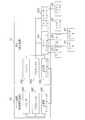
- FIG. 1is a diagram illustrating a hardware configuration example of a vehicle network system according to Embodiment 1.
- FIG. 3is a diagram illustrating a functional configuration example of an ECU according to the first embodiment.
- FIG. 3is a diagram illustrating a functional configuration example of a server apparatus according to the first embodiment. The example of the starting conditions and execution time of ECU which concern on Embodiment 1 is shown.
- FIG. 3is a diagram illustrating an example of a parameter table according to the first embodiment. The time chart figure before the update by the application C which concerns on Embodiment 1.
- FIG. FIG. 3is a flowchart showing an operation example of the server apparatus according to the first embodiment.
- FIG. 6shows an example of a parameter table after merging according to the first embodiment.
- FIG. 9shows the example of the starting condition which concerns on Embodiment 2, and execution time.
- FIG. 9is a flowchart showing an operation example of the server apparatus according to the second embodiment.
- FIG. 9is a diagram illustrating an example of a functional configuration of an ECU according to a third embodiment.
- FIG. 10is a diagram illustrating an example of a parameter table according to the third embodiment.
- FIG. 10is a time chart before update by an application C according to the third embodiment. The figure which shows the example of the starting condition and execution time after the update which concerns on Embodiment 3.
- Embodiment 1FIG.
- the vehicle network system according to Embodiment 1will be described below. More specifically, in addition to the application deadline and processing time, the data input timing from the sensor and the actuator control timing used by the application already installed in the control system ECU and the new application are used. A vehicle network system that determines whether or not an application can be updated will be described. The vehicle network system according to the present embodiment can realize advanced control even after application updating.
- FIG. 1shows a hardware configuration example of a vehicle network system according to the present embodiment.
- the vehicle network systemincludes an ECU 101 and a server device 102.
- the ECU 101 and the server device 102are connected via a wireless communication network 103.
- the ECU 101is mounted on the vehicle, and the server device 102 is disposed outside the vehicle.
- the ECU 101 and the server device 102are computers.
- the ECU 101is connected to six devices: a sensor A104, a sensor B105, a sensor C106, a sensor D107, an actuator A108, and an actuator B109.
- the ECU 101includes a sensor interface 1801, an actuator interface 1802, a memory A 1803, a processor A 1804, and a transmission / reception interface A 1805 as hardware.
- the sensor interface 1801is an interface for acquiring signals from the sensors A104 to D107.
- the actuator interface 1802is an interface for controlling the actuator A 108 and the actuator B 109.
- the memory A 1803stores various data and programs.
- the processor A 1804executes a program stored in the memory A 1803.
- the transmission / reception interface A 1805is an interface for performing communication via the wireless communication network 103.
- the server apparatus 102includes a memory B 1806, a processor B 1807, and a transmission / reception interface B 1808 as hardware.
- the memory B 1806stores various data and programs.
- the processor B 1807executes the program stored in the memory B 1806.
- the transmission / reception interface B 1808is an interface for performing communication via the wireless communication network 103.
- the ECU 101corresponds to an example of a terminal device
- the server device 102corresponds to an example of an information processing device.
- FIG. 2shows a functional configuration example of the ECU 101.
- the application A 110, the application B 111, the input control unit 113, the output control unit 114, the OS (Operating System) 115, and the update request information transmission unit 119are realized by programs. These programs are stored in the memory A 1083 and read and executed by the processor A 1804.
- the parameter table 117, the database 118, the start condition 120, and the execution time 121are information stored in the memory A 1803.
- the start condition 120 and the execution information 121are collectively referred to as system information 116.
- the input control unit 113 and the output control unit 114access the sensor interface 1801 and the actuator interface 1802 according to the execution contents.
- the input control unit 113acquires the values of the sensors A104 to D107 via the sensor interface 1801. Further, the output control unit 114 controls the actuator A 108 and the actuator B 109 using the control information via the actuator interface 1802.
- the update request information transmission unit 119communicates with the server apparatus 102 by accessing the transmission / reception interface A 1805 according to the execution content.
- FIG. 3shows a functional configuration example of the server apparatus 102.
- the application update determination unit 125is realized by a program.
- a program that implements the application update determination unit 125is stored in the memory B 1806, and is read and executed by the processor B 1807.
- the application update determination unit 125accesses the transmission / reception interface B 1808 according to the execution content to communicate with the ECU 101.
- the application update determination unit 125determines whether or not the ECU 101 can execute the application C112.
- the application update determination unit 125corresponds to an example of a communication unit and a determination unit.
- the operations performed by the application update determination unit 125correspond to examples of reception processing and determination processing.
- the application C112, the new application start condition 122, the new application execution time 123, and the new application parameter information 124are information stored in the memory B 1806.
- the application C112is downloaded to the ECU 101, it is stored in the memory A1083 like the other applications, and is read and executed by the processor A1084.
- an application A 110 and an application B 111are already installed in the ECU 101.
- Application A110 and application B111correspond to examples of installed application programs.
- the application A 110 and the application B 111perform calculations based on the data of the input information A to the input information D from the sensors A 104 to D 107 to generate the control information A and the control information B.
- Input information A to input information Dare data used by the application A110 and the application B111 for calculation.
- Control information A and control information Bare calculation results of application A110 and application B111.
- the ECU 101controls the actuator A 108 and the actuator B 109 using the control information A and the control information B to control the vehicle.
- the ECU 101downloads a new application C112 from the server device 102 as necessary, expands the functions of the application A110 and the application B111, or adds another new function, so that the vehicle suitable for the driver's preference can be obtained. Realize control.
- the application A 110When the application A 110 is activated, it performs arithmetic processing using the input information A and the input information B stored in the database 118, calculates the control information A, and stores it in the database 118.
- the application B 111When the application B 111 is activated, the application B 111 performs arithmetic processing using the input information C stored in the database 118, calculates the control information B, and stores it in the database 118.
- the input control unit 113When activated, the input control unit 113 acquires the input information A to the input information D from the sensors A 104 to D 107 at a predetermined input timing, and writes the acquired input information A to the input information D into the database 118.
- the input information A to the input information Dare used for calculation of the application A110 and the application B111.
- the output control unit 114controls the actuator A 108 using the control information A stored in the database 118 at a predetermined output timing, and controls the actuator B 109 using the control information B.
- the control information Ashows the calculation result of the application A110
- the control information Bshows the calculation result of the application B111.
- the output control unit 114controls the actuator A 108 using the control information A, so that the calculation result of the application A 110 is output to the actuator A 108. Further, when the output control unit 114 controls the actuator B109 using the control information B, the calculation result of the application B111 is output to the actuator B109.
- the OS 115activates the application A 110, the application B 111, the input control unit 113, and the output control unit 114 according to the activation condition 120.
- the OS 115sequentially executes the output control unit 114 and the input control unit 113 in a time frame in which the input control unit 113 and the output control unit 114 can be executed. After a time frame in which the input control unit 113 and the output control unit 114 can be executed, the OS 115 executes the application A110 and the application B111.
- the system information 116includes the activation condition 120 and the execution time 121.
- the execution time 121is the maximum value (worst execution time) of the length of execution time measured or estimated by the developer at the time of design.
- the execution time 121is defined for each of the application A 110 and the application B 111.
- the activation condition 120is defined for each of the application A 110, the application B 111, the input control unit 113, and the output control unit 114.
- the activation condition 120includes a priority, an activation cycle, and an activation offset.
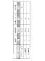
- FIG. 4shows an example of the system information 116.
- the priorities of the application A110, the application B111, the input control unit 113, and the output control unit 114are 2, 1, 3, and 3, respectively.
- the activation cyclesare all the same time tCycle.
- the activation offsets of the application A110, the application B111, the input control unit 113, and the output control unit 114are times t1, t1, t0, and t0, respectively.
- the activation offsetindicates an offset with respect to each cycle start time of the global cycle time (here, time tCycle).
- the execution time 121 (worst execution time) of the application A110 and the application B111is time tA and tB, respectively.
- execution schedules of the application A110 and the application B111 in the ECU 101are defined.
- system information 116defines an execution schedule in which the execution of the application A110 having a high priority is started at the time t1, and the execution of the application A110 is continued for the longest time tA. Further, the system information 116 defines an execution schedule in which the execution of the application B110 having a low priority is started when the execution of the application A110 is completed, and the execution of the application B111 is continued for the longest time tB.
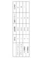
- the parameter table 117attributes of input information and attributes of control information are described.
- For the input informationas attributes, a device, a direction, an input timing, and an application that uses the input information are associated.
- For the control informationas attributes, a device, a direction, an output timing, and an application that uses the control information are associated.
- An example of the parameter table 117is shown in FIG.
- the input / output timings of the input information A to the input information C, the control information A, and the control information Bare all time t0. This value also indicates a time offset with respect to each cycle start time, similar to the start offset. Since there is no application to be used for the input information D, the input timing is not set.
- the input information A, the input information B, and the control information Aare associated with the application A110, and the input information C and the control information B are associated with the application B111. Further, it is understood that the input information A to the input information D are associated with the sensors A104 to D107, respectively, and the direction is the input direction. It can be seen that the control information A is associated with the actuator A108, and the control information B is associated with the actuator B109, and the direction is the output direction.
- one applicationis associated with each piece of information. For example, one line is added, and the application B111 is associated with the same input information A at the same time t0 or at a different timing. It may be.
- the parameter table 117defines an input / output schedule. More specifically, the parameter table 117 has an input / output schedule in which the input information A to the input information D are input at time t0, and the calculation results shown in the control information A and the control information B are output at time t0. Is defined.
- the database 118stores input information A to input information D acquired from the sensors A104 to D107, and control information A and control information B for controlling the actuator A108 and the actuator B109.
- the update request information transmission unit 119includes the parameter table 117, the system information 116 (the start condition 120 and the execution time 121), the name of the application to be updated, and the update type (overwrite, addition, deletion) as the update request information. Send to.
- the update request informationis transmitted at the time when, for example, the application A 110 receives information indicating that the update application C 112 can be used from the outside and requests the update request information transmission unit 119 to acquire the update application C 112. Etc. are considered. Since the processing related to the generation of the update request is out of the scope of the present invention, detailed description thereof is omitted.
- the update request informationincludes the parameter table 117 indicating the input / output schedules of the application A 110 and the application B 111 and the system information 116 indicating the execution schedules of the application A 110 and the application B 111. It corresponds to.
- the server apparatus 102includes an application C112, a new application start condition 122, a new application execution time 123, new application parameter information 124, and an application update determination unit 125.
- the application C112is a high-function application obtained by extending the function of the application A110, and is developed on the assumption that it is executed by the ECU 101. Therefore, when the application C112 is installed in the ECU 101, the application A110 is overwritten and updated.
- the control information Ais calculated by performing arithmetic processing using the input information A, input information B, and input information D stored in the database 118.
- the control information Ais stored in the database 118.
- the application C112is an application program that is not mounted in the ECU 101, and corresponds to an example of an unmounted application program.
- the new application activation condition 122is information used by the OS 115 as the activation condition 120 when the application C112 is executed by the ECU 101.
- the priority, the activation cycle, and the activation offsetare the same as those of the application A110.
- the new application execution time 123is an estimated value of the worst execution time when the application C112 is executed by the ECU 101.
- the new application execution time 123is a time tC and is longer than the execution time tA of the application A110.
- the new application start condition 122 and the new application execution time 123have the same role as the system information 116 in the ECU 101. That is, the execution schedule of the application C 112 is defined in the new application activation condition 122 and the new application execution time 123. More specifically, in the new application start condition 122 and the new application execution time 123, an execution schedule is defined in which the execution of the application C112 is started at the time t1, and the execution of the application C112 is continued for the longest time tC. ing.
- the new application parameter information 124is information that specifies the input timing of the input information A, input information B, and input information D used by the application C112, the output timing of the control information A, and the respective devices and directions. If input / output is performed at the input timing and output timing specified in the new application parameter information 124, it is guaranteed that the vehicle control can be normally performed by the application C112. Here, it is assumed that the input timing and output timing are set at time t0. Thus, the new application parameter information 124 defines the input / output schedule of the application C112. More specifically, the new application parameter information 124 defines an input / output schedule in which input information A, input information B, and input information D are input at time t0, and control information A is output at time t0. Yes.
- the application update determination unit 125receives update request information that is installed application information from the update request information transmission unit 119 of the ECU 101 using the transmission / reception interface B 1808. Further, the application update determination unit 125 determines whether the ECU 101 can be updated by the application C112 based on the update request information, the new application activation condition 122, the new application execution time 123, and the new application parameter information 124. More specifically, the application update determination unit 125 analyzes the input / output schedule of the application B 111 notified by the update request information and the input / output schedule of the application C 112 defined in the new application parameter information 124.
- the application update determination unit 125when the application C112 is installed in the ECU 101 and the input information of the application B111 and the calculation result of the application B111 are output according to the input / output schedule of the application B111, It is analyzed whether the input information and the calculation result of the application C112 are output according to the input / output schedule of the application C112. Further, the application update determination unit 125 analyzes the execution schedule of the application B 111 notified by the update request information and the execution schedule of the application C 112 defined in the new application activation condition 122 and the new application execution time 123.
- the application B111is executed according to the execution schedule of the application B111
- the application C112is executed according to the execution schedule of the application C112
- the execution of the application B111 and the execution of the application C112are predetermined. It is analyzed whether or not it is completed within the time frame (that is, within the activation cycle tCycle).
- the application update determination unit 125inputs the input information of the application C112 and outputs the calculation result of the application C112 according to the input / output schedule of the application C112, and the execution of the application B111 and the execution of the application C112 are within the time frame ( When it is completed within the activation cycle tCycle), it is determined that the application B111 and the application C112 can be executed by the ECU 101 and the ECU 101 can be updated by the application C112.
- the application update determination unit 125determines that the application B111 and the application C112 can be executed by the ECU 101 and the application C112 can update the ECU 101
- the application update determination unit 125uses the transmission / reception interface B1808 to determine the application C112 as the ECU 101. Send to. Further, the application update determination unit 125 also transmits information shown in FIG.
- the OS 115activates the output control unit 114 based on the activation condition 120.
- the output control unit 114refers to the parameter table 117 and confirms that the control information A and the control information B in the output direction exist at the time t0. Therefore, the output control unit 114 acquires the control information A and the control information B from the database 118. Further, the output control unit 114 controls the actuator A 108 that is the target device described in the parameter table 117 using the value of the control information A, and is described in the parameter table 117 using the value of the control information B. The actuator B109 that is the target device is controlled. When the processing of the output control unit 114 is completed, the OS 115 subsequently activates the input control unit 113.
- the input control unit 113refers to the parameter table 117 and confirms that the input information A to the input information C exists in the input direction at the time t0. Therefore, the input control unit 113 accesses the sensors A104 to C106 and acquires the input information A to input information C. Further, the input control unit 113 stores the input information A to the input information C in the database 118. This completes the processing of the input control unit 113.
- the OS 115activates the application A110 based on the activation condition 120.
- the application A110 and the application B111have the same startup offset t1, but the application A110 having a higher priority starts first.
- the application A110performs calculation using the input information A and the input information B stored in the database 118, calculates the control information A, stores the control information A in the database 118, and ends the process.
- the OS 115activates the application B111.
- the application B111performs calculation using the input information C stored in the database 118, calculates the control information B, stores the control information B in the database 118, and ends the process.
- FIG. 7corresponds to an example of an information processing method and an information processing program.
- the application update determination unit 125deletes the part associated with the application to be overwritten from the update request information received from the ECU 101 (step S501).
- the application update determination unit 125sets the values set as the timings of the input information and control information of the parameter table 117 subjected to the deletion process, and the timings of the input information and control information of the new application parameter information 124. Extracted values are extracted (step S502).
- step S503the application update determination unit 125 determines whether the number of pieces of input information or control information at the same timing is equal to or less than NMax (step S503).
- step S503the application update determination unit 125 executes the application C112 when the application C112 is installed in the ECU 101 and the input information of the application B111 and the calculation result of the application B111 are output according to the input / output schedule of the application B111. It is determined whether the input information of C112 and the output of the calculation result of application C112 are performed according to the input / output schedule of application C112.
- the application update determination unit 125includes information on the activation condition 120 and execution time 121 of the ECU 101 that has been subjected to the deletion process, and activation of a new application.
- the start time and end time of each applicationare calculated using the condition 122, the information on the new application execution time 123, and each parameter information (step S504).
- the application update determination unit 125determines whether the end time of each application is earlier than either the output timing of the control information output by the application or the next start time of the application itself ( Step S505).
- step S504 and step S505the application update determination unit 125, when the application C112 is installed in the ECU 101, the application B111 is executed according to the execution schedule of the application B111, and the application C112 is executed according to the execution schedule of the application C112. It is determined whether or not the execution of the application B111 and the execution of the application C112 are completed within a predetermined time frame.
- step S505the application update determination unit 125 determines that the ECU 101 can be updated by the new application C112 (step S506), and ends the process. On the other hand, when the number of input information or control information at the same timing exceeds NMax, or when the application end time is later, the application update determination unit 125 cannot update the ECU 101 by the new application C112. (Step S507) and the process is terminated.
- the application update determination unit 125When receiving the information shown in FIG. 4 and FIG. 5 as the update request information from the ECU 101, the application update determination unit 125 deletes the information associated with the application A110 that is the overwriting target. As a result, the update request information is as shown in FIGS. In FIGS. 8 and 9, the hatched lines are deleted lines. Next, the application update determination unit 125 merges the information in the parameter table 117 in FIG. 9 and the new application parameter information 124 as shown in FIG. As a result, it can be seen that all the six pieces of information are all at the same timing t0. Here, it is assumed that the value of NMax is 10. Since 6 ⁇ NMax, the application update determination unit 125 obtains the information on the activation condition 120 and the execution time 121 in FIG.
- the time chart as shown in FIG. 11is generated and the start time and end time of the application are obtained.
- the time chart of FIG. 11is a time chart when the application C112 is mounted on the ECU 101, the application B111 is executed according to the execution schedule of the application B111, and the application C112 is executed according to the execution schedule of the application C112. From the time chart of FIG. 11, the worst execution time of the application C112 is a time tC, which is longer than the time tA of the application A110. However, since the end times of the application C112 and the application B111 end earlier than the next output timing t0, the application update determination unit 125 determines that the application A110 can be overwritten by the application C112 and ends the processing.
- the server apparatus 102determines whether or not the input / output timing required for the input information and control information used by the existing application B111 and the new application C112 is satisfied before the update by the application C112. I do.
- the application of the ECU 101is updated only after it is confirmed that the execution time and the input / output timing are satisfied. Therefore, the input information is acquired from the sensor at the input timing intended by the application developer, and the intended output is obtained.
- the actuatorcan be controlled using the control information at the timing. As a result, it is possible to avoid a situation in which the application C112 or the existing application B111 does not operate normally after the update.
- the developer of the application C112does not need to have the information of the application B111 at the development stage, and the server apparatus uses the input / output timing information used when testing the application C112 as the timing for guaranteeing the normal operation of the application C112. 102 only need to be provided. Therefore, it is not necessary to acquire and test information on the application B111, and the number of development steps can be reduced. That is, since it is not necessary to perform operation verification covering a vast number of mounting patterns, the development man-hours required for verification can be reduced.
- the information that can be arranged at the same input / output timingis limited by the number (NMax) in step S503 of FIG.
- the time required for inputting the input information and outputting the control informationmay be obtained, and information that can be arranged at the same input / output timing may be limited by the input / output time.
- the processing time of the OS 115 itself for starting and ending the application and the processing time when an interrupt occursare not described.
- the application update determination unit 125determines these processing times. It may be determined whether or not update is possible.
- Embodiment 2FIG. The vehicle network system according to Embodiment 2 will be described below. In the following, differences from the first embodiment will be mainly described. Matters not described below are the same as those in the first embodiment.
- System information 116is shown in FIG. As shown in FIG. 12, in the present embodiment, the activation cycle of the input control unit 113 and the output control unit 114 is tCycle / 3.
- the time t3is a time when two-thirds of the time tCycle has passed since the start of the cycle of each application.
- a time widthis set in the input / output schedule of the application C112.
- the application update determination unit 125installs the application C112 in the ECU 101 when the time width is set in the input / output schedule of the application C112, which is an unimplemented application program, and updates the input information of the application B111.
- the input and the output of the calculation result of the application B111are performed according to the input / output schedule of the application B111, the input information of the application C112 and the output of the calculation result of the application C112 are the time width of the input / output schedule of the application C112. Analyzes whether or not it is performed at any timing within the range.
- step S503If the application update determination unit 125 determines that the number of input information and control information at the same timing exceeds NMax (step S503), the application update determination unit 125 is still trying out of the input information and control information at a timing exceeding NMax. It is determined whether there is anything that can be changed to a timing not yet set (step S1001). If there is nothing that can be changed, the application update determination unit 125 determines that the ECU 101 cannot be updated by the application C112 (step S507), and ends the process. On the other hand, if there is something that can be changed, the application update determination unit 125 changes the timing of the corresponding input information or control information (step S1002), and returns to step S502 again.
- the input control unit 113can be activated on the ECU 101 to acquire the input information D and can be used for the calculation of the application C112.
- the application update determination unit 125changes the timing of the input information D to time t3, and extracts information input / output at time t0 and time t3.
- the operation of the ECU 101 when the application A110 is overwritten and updated with the application C112 in this waywill be described with reference to the time chart of FIG. Since the time frame capable of executing the input control unit 113 and the output control unit 114 activated at time t0 is already used for input / output of five pieces of input information and control information, the input information D is input at time t3. Acquired when the control unit 113 is activated.
- the application C112 activated at time t1performs calculation using the input information D acquired at the immediately previous time t3 and the values of the input information A and the input information B acquired at the immediately preceding time t0.
- the application C112operates normally even if the input information D acquired at time t3 is used in the new application parameter information 124 of the application C112. For this reason, it is not necessary to perform a test in which the application B111 and the application C112 are mounted, and the development man-hour can be reduced.
- the input timing of the input information included in the new application parameter information 124is set by the time width.
- controlis performed.
- the information output timingmay be set by a time width.
- the input timing of the input information and the output timing of the control information included in the parameter table 117 of the ECU 101may be set as a time width.
- the application update determination unit 125is configured so that the application C112 is mounted on the ECU 101, and the input information of the application B111 and the calculation result of the application B111 are output.
- the input timing of input informationis set within a range.
- the input timing of input information and the output timing of control informationmay be set by a plurality of discrete values.
- the application update determination unit 125operates as shown in FIG.
- Embodiment 3FIG. The vehicle network system according to Embodiment 3 will be described below. In the following, differences from the first embodiment will be mainly described. Matters not described below are the same as those in the first embodiment.
- FIG. 15shows a functional configuration example of the ECU 101 according to the present embodiment. 15, the same elements as those in FIG. 2 are denoted by the same reference numerals.
- An actuator C1301is connected to the ECU 101.
- the ECU 101also includes a time measurement unit 1302. The other elements are the same as in FIG.
- the functional configuration of the server apparatus 102is the same as that in FIG.
- the system information 116 in the initial state in the third embodimentis the same as that in FIG.
- FIG. 16shows the parameter table 117 in the third embodiment.
- a column of control information Cis added to FIG. 5, but since there is no application to be used in the initial state, no output timing is set.
- the time measuring unit 1302is realized by a program.
- a program for realizing the time measurement unit 1302is stored in the memory A 1083, and the processor A 1804 reads out and executes the program.
- the time measuring unit 1302measures the execution time of the application. More specifically, the time measurement unit 1302 starts measurement when the OS 115 activates the application, and stops measurement when the processing of the application ends. In addition, the time measurement unit 1302 compares the measurement result of the execution time with the information of the execution time 121 included in the system information 116. When the measurement result is equal to or less than the value of the execution time 121 included in the system information 116, the measurement result is discarded.
- the time measurement unit 1302updates the information of the execution time 121 of the system information 116 with the measurement result.
- the execution time 121 included in the system information 116 in the initial stateis the worst execution time estimated at the time of design, there is a possibility that the worst execution time is calculated to be shorter than the actual due to an estimation error or the like. Therefore, the execution time 121 is updated with the measurement result by the time measurement unit 1302.
- the application C112is an application that realizes a function different from the application A110 and the application B111. For this reason, when the application C112 is mounted on the ECU 101, the application C112 does not overwrite the application A110 or the application B111, and the application C112 is newly added to the ECU 101.
- the application C112When the application C112 is started on the ECU 101, the application C112 performs arithmetic processing using the input information A, input information B, and input information D stored in the database 118, calculates control information C, and controls information C is stored in the database 118.
- the new application activation condition 122is information used by the OS 115 as the activation condition 120 when the application C112 is executed by the ECU 101.
- the priorityis 0, the activation cycle is tCycle, and the activation offset is time t0.
- the new application execution time 123is an estimated value of the worst execution time when the application C112 is executed by the ECU 101, and is assumed to be time tD.
- the new application parameter information 124is information for specifying the input timing of the input information A, input information B, and input information D used by the application C112, the output timing of the control information C, and the respective devices and directions. If input / output is performed at the input / output timing of the new application parameter information 124, it is guaranteed that normal vehicle control is possible by the application C112. Here, it is assumed that the input / output timings are all set to time t0.
- the OS 115activates the application A110 based on the activation condition 120. Then, the time measuring unit 1302 starts measuring the execution time. Next, when the application A 110 ends the process at time t 2, the time measurement unit 1302 ends the measurement of the execution time, and compares the measurement result of the execution time with the value of the execution time 121 included in the system information 116.
- update request information for notifying the execution time tA ′ measured by the time measurement unit 1302is received as the execution time of the application A110, and whether or not the application C112 can be updated using the execution time tA ′. judge.
- the application update determination unit 125obtains the start time and end time of the application from the generated time chart. As a result, since the end time of the application C112 is later than the output timing t0 of the control information C output by the application C112, the application update determination unit 125 determines that additional update of the application C112 is impossible and performs processing. finish.
- the application C112can be executed after the processing of the output control unit 114 and the input control unit 113 at time t0 and before the application A110 is activated at time t1. Is possible. For this reason, it can be determined that the update is possible if the determination is made only in terms of the execution time margin (idle time). However, if additional updating is performed without considering the output timing in this way, control of the actuator C1301 using the control information C output from the application C112 is performed after the next application C112 is activated. Therefore, the control timing is delayed by almost one cycle (tCycle) and is not output at the timing intended by the developer of the application C112.
- tCyclealmost one cycle
- the application update determination unit 125executes the application A110, the application B111, and the application C112 according to the execution schedule, is the execution of the application A110, the application B111, and the application C112 completed by the output timing of each control information? Determine whether or not.
- the application update determination unit 125does not permit the application C112 to be mounted on the ECU 101.
- the application update determination unit 125performs the determination by estimating the execution time of the application A110 to be shorter than the actual time. For this reason, the application update determination unit 125 may determine that the end time of the application C112 is earlier than the output timing of the control information C, and may erroneously determine that the application C112 can be added. If the measurement result of the execution time of the application on the ECU 101 is longer than the worst execution time estimated at the time of design as in the present embodiment, the application result can be added by using the measurement result as the execution time 121. Whether or not it is possible can be determined with high accuracy. As a result, it is possible to avoid a situation in which the application does not operate normally in the ECU 101 after the application is added.
- a processor A 1804 and a processor B 1807 illustrated in FIG. 1are ICs (Integrated Circuits) that perform processing.
- the processor A 1804 and the processor B 1807are a CPU (Central Processing Unit), a DSP (Digital Signal Processor), and the like.
- the memory A 1803 and the memory B 1806are a RAM (Random Access Memory), a ROM (Read Only Memory), a flash memory, an HDD (Hard Disk Drive), and the like.
- the transmission / reception interface A 1805 and the transmission / reception interface B 1808include a receiver that receives data and a transmitter that transmits data.
- the transmission / reception interface A 1805 and the transmission / reception interface B 1808are, for example, a communication chip or a NIC (Network Interface Card).
- information, data, signal values, and variable values indicating the processing results of the application A110, the application B111, the input control unit 113, the output control unit 114, the OS 115, the update request information transmission unit 119, and the time measurement unit 1302are stored.
- the programs for realizing the application A110, the application B111, the input control unit 113, the output control unit 114, the OS 115, the update request information transmission unit 119, and the time measurement unit 1302are magnetic disk, flexible disk, optical disk, compact disk, Blu-ray ( It may be stored in a portable storage medium such as a registered trademark disk or DVD.
- information, data, signal values, and variable values indicating the processing results of the application update determination unit 125are stored in the memory B 1806, a register in the processor B 1807, or a cache memory.
- the program that implements the application update determination unit 125may be stored in a portable storage medium such as a magnetic disk, a flexible disk, an optical disk, a compact disk, a Blu-ray (registered trademark) disk, or a DVD.
- the ECU 101 and the server apparatus 102may be realized by an electronic circuit such as a logic IC (Integrated Circuit), a GA (Gate Array), an ASIC (Application Specific Integrated Circuit), or an FPGA (Field-Programmable Gate Array).
- the processor and the electronic circuitare also collectively referred to as a processing circuit.
Landscapes
- Engineering & Computer Science (AREA)
- Theoretical Computer Science (AREA)
- Software Systems (AREA)
- General Engineering & Computer Science (AREA)
- Physics & Mathematics (AREA)
- General Physics & Mathematics (AREA)
- Computer Security & Cryptography (AREA)
- Quality & Reliability (AREA)
- Stored Programmes (AREA)
Abstract
Description
Translated fromJapanese 本発明は、アプリケーションプログラム(以下、単にアプリケーションともいう)の更新に関する。
以下では、車載電子制御装置(以下、ECU:Engine Control Unitという)で実行されるアプリケーションの更新について説明する。The present invention relates to updating an application program (hereinafter also simply referred to as an application).
Below, the update of the application performed with a vehicle-mounted electronic control apparatus (henceforth ECU: Engine Control Unit) is demonstrated.
自動車には、エンジンの点火時期やステアリングモータの制御を行うECUが搭載されている。従来、加速、操舵、制動に関わる安全クリティカルな制御を行うECU(以下、制御系ECUという)は、車内ネットワークにのみ接続されており、車外ネットワークとは分離されていた。また、これらの制御系ECUに搭載されているアプリケーションの更新は日常的には行われず、サービスキャンペーンやリコール発生時にディーラでアプリケーションの更新を行う程度であった。The car is equipped with an ECU that controls the ignition timing of the engine and the steering motor. Conventionally, an ECU that performs safety-critical control related to acceleration, steering, and braking (hereinafter referred to as a control system ECU) is connected only to the in-vehicle network and separated from the outside network. In addition, the application installed in these control system ECUs is not updated on a daily basis, and the application is updated by a dealer when a service campaign or a recall occurs.
しかし、今後は制御系ECUが接続されている車内ネットワークが車外ネットワークと接続され、ディーラ経費の削減等を目的としてクラウドネットワークからの無線通信を介して制御系ECUのアプリケーションの書換えが行われるようになる。さらに、安全運転支援システムや自動走行システムが提供する様々なレベルでの運転支援機能や、各ドライバの嗜好に対応する機能を実現するアプリケーションが制御系ECUに求められる。このため、スマートフォンへのアプリケーション追加と同様に、車の購入後もアプリケーションの改良やアップグレードなどによる制御系ECUのアプリケーションの上書き、追加、削除(以下、上書き、追加、削除をまとめて更新という)がクラウドネットワークから行われるようになると考えられる。However, in the future, the in-vehicle network to which the control system ECU is connected will be connected to the external network, and the application of the control system ECU will be rewritten via wireless communication from the cloud network for the purpose of reducing dealer costs. Become. Further, the control system ECU is required to have an application that realizes driving support functions at various levels provided by the safe driving support system and the automatic driving system and functions corresponding to the preferences of each driver. For this reason, as with the addition of applications to smartphones, control system ECU applications can be overwritten, added, or deleted (hereinafter referred to as overwriting, adding, or deleting collectively) even after purchasing a car by improving or upgrading the application. It will be done from the cloud network.
制御系ECUにおけるアプリケーションの更新では、既存のアプリケーションが正常に動作することや、新しいアプリケーションを既定のタイミングで実行できることはもちろん、各アプリケーションが使用するセンサからのデータ入力タイミングやアクチュエータの制御タイミングも、アプリケーションに合わせて実現できるか否か考慮する必要がある。これらデータ入力タイミング及び制御タイミングを満足することで、アプリケーションの更新後もアプリケーション開発者が意図した制御を実現することができる。In the application update in the control system ECU, the existing application operates normally, the new application can be executed at a predetermined timing, as well as the data input timing from the sensor used by each application and the control timing of the actuator, It is necessary to consider whether it can be realized according to the application. By satisfying these data input timing and control timing, the control intended by the application developer can be realized even after the application is updated.
従来の制御系ECUでは、アプリケーションの実装パターンは仕向地やオプション毎に存在する程度で、その数が限られていた。このため、アプリケーションの更新を行う際には、新しいアプリケーションの開発毎に、更新対象の制御系ECUの実装パターンを全て網羅して前述のタイミング等を含めた検証を行い、更新可否を判定することが可能であった。In conventional control system ECUs, there are only a limited number of application implementation patterns for each destination and option. For this reason, when updating an application, every time a new application is developed, all the implementation patterns of the control system ECU to be updated are covered, and the verification including the timing described above is performed to determine whether the update is possible. Was possible.
しかし、前述のように多様な要求に応じて制御系ECUが出荷後にもカスタマイズされるようになると、検証が必要な実装パターンは膨大になる。そのうえ、カーメーカや新しいアプリケーションの開発者が、更新対象の制御系ECUに既に実装されているアプリケーションを全て把握しているとは限らない。このような未知のアプリケーションを含んだ制御系ECU、すなわちアプリケーション開発段階では検証を行うことができない実装パターンの制御系ECUを新しいアプリケーションで更新すると、制御系ECUが異常状態となって車両の制御ができなくなり、車が動かなかったり、事故が発生したりする可能性がある。したがって、アプリケーションの更新前に、対象とする制御系ECUでのアプリケーション更新が可能であるか個別に判定する必要がある。However, as described above, if the control ECU is customized even after shipment according to various requirements, the number of mounting patterns that need to be verified becomes enormous. In addition, car manufacturers and new application developers do not always know all the applications already installed in the control ECU to be updated. When a control system ECU including such an unknown application, that is, a control system ECU having a mounting pattern that cannot be verified at the application development stage, is updated with a new application, the control system ECU becomes in an abnormal state and the vehicle is controlled. It may become impossible, and the car may not move or an accident may occur. Therefore, before updating the application, it is necessary to individually determine whether the application can be updated in the target control system ECU.
アプリケーションの更新可否判定を行う方法として、例えば特許文献1では、アプリケーションのデッドライン、処理時間、制御系ECU間の通信時間を考慮して判定を行う方法が開示されている。As a method for determining whether or not an application can be updated, for example,
しかしながら上記特許文献1では、制御系ECUに既に実装されているアプリケーションや新しいアプリケーションが使用する、センサからのデータ入力タイミングやアクチュエータの制御タイミングについては考慮されていない。したがって更新内容によっては所望のタイミングよりも一周期近く前のセンサからの古いデータをアプリケーションの演算に使用したり、所望のタイミングよりも一周期近く遅れた制御を行ったりする可能性がある。このような場合には、アプリケーション開発時に想定した車両の制御ができなくなるという課題がある。However, in the above-mentioned
本発明は、前述の課題を解決することを主な目的としており、アプリケーションプログラムの更新後も、アプリケーションプログラムへの入力情報が適切なタイミングで入力され、アプリケーションプログラムの演算結果が適切なタイミングで出力されるようにすることを主な目的とする。The main object of the present invention is to solve the above-described problems. Even after the application program is updated, input information to the application program is input at an appropriate timing, and an operation result of the application program is output at an appropriate timing. The main purpose is to be.
本発明に係る情報処理装置は、
端末装置から、前記端末装置に実装済の実装済アプリケーションプログラムが演算に用いる入力情報が入力され、前記実装済アプリケーションプログラムの演算結果が出力される入出力スケジュールを通知する実装済アプリケーション情報を受信する通信部と、
前記実装済アプリケーション情報で通知された前記実装済アプリケーションプログラムの入出力スケジュールと、前記端末装置に未実装の未実装アプリケーションプログラムが演算に用いる入力情報が入力され、前記未実装アプリケーションプログラムの演算結果が出力される入出力スケジュールとを解析して、前記実装済アプリケーションプログラムと前記未実装アプリケーションプログラムとが前記端末装置で実行可能であるか否かを判定する判定部とを有する。An information processing apparatus according to the present invention includes:
Input information used by a mounted application program mounted on the terminal device for calculation is input from the terminal device, and received mounted application information for notifying an input / output schedule for outputting a calculation result of the mounted application program is received. A communication department;
The input / output schedule of the mounted application program notified by the mounted application information and input information used by the unmounted unmounted application program for calculation in the terminal device are input, and the calculation result of the unmounted application program is A determination unit that analyzes the output I / O schedule and determines whether the mounted application program and the unmounted application program can be executed by the terminal device;
本発明では、実装済アプリケーションプログラムの入出力スケジュールと、未実装アプリケーションプログラムの入出力スケジュールとを解析して、実装済アプリケーションプログラムと未実装アプリケーションプログラムとが端末装置で実行可能であるか否かを判定する。このため、本発明によれば、アプリケーションプログラムの更新後も、端末装置では、アプリケーションプログラムへの入力情報が適切なタイミングで入力され、アプリケーションプログラムの演算結果が適切なタイミングで出力される。In the present invention, the input / output schedule of the mounted application program and the input / output schedule of the unmounted application program are analyzed to determine whether the mounted application program and the unmounted application program can be executed by the terminal device. judge. For this reason, according to the present invention, even after the application program is updated, the terminal device inputs the input information to the application program at an appropriate timing, and outputs the calculation result of the application program at the appropriate timing.
実施の形態1.
以下に、実施の形態1に係る車両用ネットワークシステムを説明する。
より具体的には、以下にて、アプリケーションのデッドラインや処理時間に加えて、制御系ECUに既に実装されているアプリケーションや新しいアプリケーションが使用する、センサからのデータ入力タイミングやアクチュエータの制御タイミングを考慮してアプリケーションの更新可否を判定する車両用ネットワークシステムを説明する。本実施の形態に係る車両用ネットワークシステムにより、アプリケーション更新後も高度な制御を実現することができる。
The vehicle network system according to Embodiment 1 will be described below.
More specifically, in the following, in addition to the application deadline and processing time, the data input timing from the sensor and the actuator control timing used by the application already installed in the control system ECU and the new application are used. A vehicle network system that determines whether or not an application can be updated will be described. The vehicle network system according to the present embodiment can realize advanced control even after application updating.
***構成の説明***
図1は、本実施の形態に係る車両用ネットワークシステムのハードウェア構成例を示す。
車両用ネットワークシステムはECU101とサーバ装置102で構成される。ECU101とサーバ装置102は無線通信網103を介して接続している。ECU101は車両に搭載されており、サーバ装置102は車両外に配置されている。ECU101とサーバ装置102は、それぞれコンピュータである。
ECU101はセンサA104、センサB105、センサC106、センサD107、アクチュエータA108、アクチュエータB109の6つのデバイスと接続している。ECU101はハードウェアとして、センサインタフェース1801と、アクチュエータインタフェース1802と、メモリA1803とプロセッサA1804と送受信インタフェースA1805を備える。センサインタフェース1801は、センサA104~センサD107から信号を取得するためのインタフェースである。アクチュエータインタフェース1802は、アクチュエータA108とアクチュエータB109を制御するためのインタフェースである。メモリA1803は、各種データ及びプログラムを記憶する。プロセッサA1804は、メモリA1803に記憶されているプログラムを実行する。送受信インタフェースA1805は、無線通信網103を介した通信を行うためのインタフェースである。
サーバ装置102は、ハードウェアとして、メモリB1806とプロセッサB1807と送受信インタフェースB1808を備える。
メモリB1806は、各種データ及びプログラムを記憶する。プロセッサB1807は、メモリB1806に記憶されているプログラムを実行する。送受信インタフェースB1808は、無線通信網103を介した通信を行うためのインタフェースである。
なお、ECU101は端末装置の例に相当し、サーバ装置102は情報処理装置の例に相当する。*** Explanation of configuration ***
FIG. 1 shows a hardware configuration example of a vehicle network system according to the present embodiment.
The vehicle network system includes an
The
The
The
The
図2は、ECU101の機能構成例を示す。
アプリケーションA110、アプリケーションB111、入力制御部113、出力制御部114、OS(Operating System)115、更新要求情報送信部119は、プログラムにより実現される。これらプログラムは、メモリA1083に記憶され、プロセッサA1804が読み出して実行する。
また、パラメータテーブル117、データベース118、起動条件120、実行時間121はメモリA1803に記憶されている情報である。起動条件120と実行情報121の2つを合わせてシステム情報116と呼ぶ。
入力制御部113と出力制御部114は、プロセッサA1804で実行されると、実行内容に応じてセンサインタフェース1801やアクチュエータインタフェース1802へアクセスする。より具体的には、入力制御部113は、センサインタフェース1801を介して、センサA104~センサD107の値を取得する。また、出力制御部114は、アクチュエータインタフェース1802を介して、制御情報を用いてアクチュエータA108とアクチュエータB109を制御する。
更新要求情報送信部119は、プロセッサA1804で実行されると、実行内容に応じて送受信インタフェースA1805へアクセスしてサーバ装置102と通信を行う。FIG. 2 shows a functional configuration example of the
The
The parameter table 117, the
When executed by the
When executed by the
図3は、サーバ装置102の機能構成例を示す。
アプリケーション更新判定部125は、プログラムにより実現される。アプリケーション更新判定部125を実現するプログラムはメモリB1806に記憶され、プロセッサB1807が読み出して実行する。アプリケーション更新判定部125は、プロセッサB1807で実行されると、実行内容に応じて送受信インタフェースB1808へアクセスしてECU101と通信を行う。また、アプリケーション更新判定部125は、プロセッサB1807で実行されると、ECU101がアプリケーションC112を実行できるか否かを判定する。アプリケーション更新判定部125は、通信部及び判定部の例に相当する。また、アプリケーション更新判定部125により行われる動作は、受信処理及び判定処理の例に相当する。
アプリケーションC112、新アプリケーション起動条件122、新アプリケーション実行時間123、新アプリケーションパラメータ情報124はメモリB1806に記憶されている情報である。
アプリケーションC112はECU101へダウンロードされると、他のアプリケーションと同様にメモリA1083に記憶され、プロセッサA1084が読み出して実行する。FIG. 3 shows a functional configuration example of the
The application
The application C112, the new
When the application C112 is downloaded to the
***動作の説明***
次に、ECU101の動作概要を説明する。
図2に示すように、ECU101にはアプリケーションA110とアプリケーションB111が実装済である。アプリケーションA110とアプリケーションB111は実装済アプリケーションプログラムの例に相当する。
アプリケーションA110とアプリケーションB111は、センサA104~センサD107からの入力情報A~入力情報Dのデータを基に演算を行い、制御情報Aと制御情報Bを生成する。入力情報A~入力情報Dは、アプリケーションA110とアプリケーションB111が演算に用いるデータである。制御情報Aと制御情報Bは、アプリケーションA110とアプリケーションB111の演算結果である。
ECU101は制御情報Aと制御情報Bを用いてアクチュエータA108とアクチュエータB109を制御し、車両の制御を行う。
また、ECU101は必要に応じてサーバ装置102から新しいアプリケーションC112をダウンロードし、アプリケーションA110やアプリケーションB111の機能を拡張したり、別の新しい機能を追加したりして、ドライバの好みに合った車両の制御を実現する。*** Explanation of operation ***
Next, an outline of the operation of the
As shown in FIG. 2, an
The
The
Further, the
次に、ECU101の各機能を説明する。Next, each function of the
アプリケーションA110は、起動するとデータベース118に格納されている入力情報Aと入力情報Bを用いて演算処理を行い、制御情報Aを算出し、データベース118に格納する。When the
アプリケーションB111は、起動するとデータベース118に格納されている入力情報Cを用いて演算処理を行い、制御情報Bを算出し、データベース118に格納する。When the
入力制御部113は、起動すると既定の入力タイミングでセンサA104~センサD107から入力情報A~入力情報Dを取得し、取得した入力情報A~入力情報Dをデータベース118へ書込む。
入力情報A~入力情報Dは、アプリケーションA110及びアプリケーションB111の演算に用いられる。When activated, the
The input information A to the input information D are used for calculation of the application A110 and the application B111.
出力制御部114は、起動すると既定の出力タイミングでデータベース118に格納されている制御情報Aを用いてアクチュエータA108を制御し、制御情報Bを用いてアクチュエータB109を制御する。
制御情報AにはアプリケーションA110の演算結果が示され、制御情報BにはアプリケーションB111の演算結果が示される。出力制御部114が制御情報Aを用いてアクチュエータA108を制御することによりアプリケーションA110の演算結果がアクチュエータA108に出力される。また、出力制御部114が制御情報Bを用いてアクチュエータB109を制御することによりアプリケーションB111の演算結果がアクチュエータB109に出力される。When activated, the
The control information A shows the calculation result of the application A110, and the control information B shows the calculation result of the application B111. The
OS115は、起動条件120に従ってアプリケーションA110、アプリケーションB111、入力制御部113、出力制御部114を起動する。
なお、実施の形態1では、OS115は、入力制御部113と出力制御部114を実行可能な時間枠において、出力制御部114、入力制御部113の順に続けて実行する。入力制御部113と出力制御部114を実行可能な時間枠の経過後に、OS115は、アプリケーションA110とアプリケーションB111を実行する。The
In the first embodiment, the
前述のように、システム情報116は、起動条件120と実行時間121を含む。
実行時間121は、開発者が設計時に測定あるいは見積もった実行時間の長さの最大値(最悪実行時間)である。実行時間121は、アプリケーションA110、アプリケーションB111の各々に対して定義されている。
起動条件120は、アプリケーションA110、アプリケーションB111、入力制御部113、出力制御部114の各々に対して定義されている。起動条件120は、優先度、起動周期、起動オフセットで構成されている。
図4は、システム情報116の例を示す。
アプリケーションA110、アプリケーションB111、入力制御部113、出力制御部114の優先度は夫々2、1、3、3である。ここで優先度は大きい値ほど高いものとする。起動周期は全て同じ時間tCycleである。アプリケーションA110、アプリケーションB111、入力制御部113、出力制御部114の起動オフセットは夫々時間t1、t1、t0、t0である。起動オフセットは、グローバルな周期時間(ここでは時間tCycle)の各周期開始時刻に対するオフセットを指す。また、アプリケーションA110、アプリケーションB111の実行時間121(最悪実行時間)は夫々時間tA、tBである。
システム情報116には、ECU101でのアプリケーションA110とアプリケーションB111の実行スケジュールが定義されている。より具体的には、システム情報116には、優先度の高いアプリケーションA110の実行が時刻t1に開始され、アプリケーションA110の実行は最長で時間tAの間継続するという実行スケジュールが定義されている。更に、システム情報116には、アプリケーションA110の実行が完了したら優先度の低いアプリケーションB110の実行が開始され、アプリケーションB111の実行は最長で時間tBの間継続するという実行スケジュールが定義されている。As described above, the
The
The
FIG. 4 shows an example of the
The priorities of the application A110, the application B111, the
In the
パラメータテーブル117では、入力情報の属性と制御情報の属性が記述される。
入力情報に対しては、属性として、デバイス、方向、入力タイミングと、その入力情報を使用するアプリケーションとが関連付けられる。また、制御情報に対しては、属性として、デバイス、方向、出力タイミングと、その制御情報を使用するアプリケーションとが関連付けられる。
パラメータテーブル117の例を図5に示す。
入力情報A~入力情報C、制御情報A、制御情報Bの入出力タイミングは全て時間t0である。この値も、起動オフセットと同様に各周期開始時刻に対する時間のオフセットを指す。入力情報Dは、使用するアプリケーションが存在しないため、入力タイミングは設定されていない。入力情報A、入力情報B、制御情報AにはアプリケーションA110が、入力情報Cと制御情報BにはアプリケーションB111が関連付けられている。また、入力情報A~入力情報Dには夫々センサA104~センサD107が関連付けられ、方向が入力方向であることがわかる。制御情報AにはアクチュエータA108、制御情報BにはアクチュエータB109が関連付けられ、方向が出力方向であることがわかる。ここでは各情報に対してアプリケーションが1つ関連付けられているが、例えば一行追加して、同じ入力情報Aに対して、アプリケーションB111が、同じタイミングの時間t0、または違うタイミングで関連付けられるようなものであってもよい。
パラメータテーブル117には、入出力スケジュールが定義されている。より具体的には、パラメータテーブル117には、入力情報A~入力情報Dが時刻t0に入力され、制御情報A及び制御情報Bに示される演算結果が時刻t0に出力されるという入出力スケジュールが定義されている。In the parameter table 117, attributes of input information and attributes of control information are described.
For the input information, as attributes, a device, a direction, an input timing, and an application that uses the input information are associated. In addition, for the control information, as attributes, a device, a direction, an output timing, and an application that uses the control information are associated.
An example of the parameter table 117 is shown in FIG.
The input / output timings of the input information A to the input information C, the control information A, and the control information B are all time t0. This value also indicates a time offset with respect to each cycle start time, similar to the start offset. Since there is no application to be used for the input information D, the input timing is not set. The input information A, the input information B, and the control information A are associated with the application A110, and the input information C and the control information B are associated with the application B111. Further, it is understood that the input information A to the input information D are associated with the sensors A104 to D107, respectively, and the direction is the input direction. It can be seen that the control information A is associated with the actuator A108, and the control information B is associated with the actuator B109, and the direction is the output direction. Here, one application is associated with each piece of information. For example, one line is added, and the application B111 is associated with the same input information A at the same time t0 or at a different timing. It may be.
The parameter table 117 defines an input / output schedule. More specifically, the parameter table 117 has an input / output schedule in which the input information A to the input information D are input at time t0, and the calculation results shown in the control information A and the control information B are output at time t0. Is defined.
データベース118は、センサA104~センサD107から取得した入力情報A~入力情報D、およびアクチュエータA108とアクチュエータB109を制御するための制御情報Aと制御情報Bを格納する。The
更新要求情報送信部119は、パラメータテーブル117と、システム情報116(起動条件120と実行時間121)と、更新したいアプリケーション名と更新種別(上書き、追加、削除)を、更新要求情報としてサーバ装置102へ送信する。
更新要求情報の送信のタイミングは、例えばアプリケーションA110が外部から更新用アプリケーションC112を利用可能であることを示す情報を受信して、更新要求情報送信部119に更新用アプリケーションC112の取得を要求する時点などが考えられる。更新要求の生成に関わる処理は本発明の対象外であるため詳細な説明は省略する。
更新要求情報は、前述のように、アプリケーションA110及びアプリケーションB111の入出力スケジュールが示されるパラメータテーブル117とアプリケーションA110及びアプリケーションB111の実行スケジュールが示されるシステム情報116とを含み、実装済アプリケーション情報の例に相当する。The update request
The update request information is transmitted at the time when, for example, the
As described above, the update request information includes the parameter table 117 indicating the input / output schedules of the
図3に示すように、サーバ装置102は、アプリケーションC112、新アプリケーション起動条件122、新アプリケーション実行時間123、新アプリケーションパラメータ情報124、アプリケーション更新判定部125を備える。3, the
アプリケーションC112は、アプリケーションA110の機能を拡張した高機能アプリケーションであり、ECU101で実行されることを想定して開発されている。したがってアプリケーションC112をECU101に実装する場合には、アプリケーションA110を上書き更新することになる。アプリケーションC112はECU101上で起動すると、データベース118に格納されている入力情報A、入力情報B、入力情報Dを用いて演算処理を行い、制御情報Aを算出する。制御情報Aは、データベース118に格納される。
アプリケーションC112は、ECU101に未実装のアプリケーションプログラムであり、未実装アプリケーションプログラムの例に相当する。The application C112 is a high-function application obtained by extending the function of the application A110, and is developed on the assumption that it is executed by the
The application C112 is an application program that is not mounted in the
新アプリケーション起動条件122は、アプリケーションC112がECU101で実行される場合にOS115が起動条件120として用いる情報である。ここでは、優先度、起動周期、起動オフセットはアプリケーションA110と同じとする。The new
新アプリケーション実行時間123は、アプリケーションC112がECU101で実行される場合の最悪実行時間の見積もり値である。ここでは、新アプリケーション実行時間123は時間tCとし、アプリケーションA110の実行時間tAよりも長いものとする。The new
新アプリケーション起動条件122及び新アプリケーション実行時間123は、ECU101におけるシステム情報116と同様な役割を持つ。つまり、新アプリケーション起動条件122及び新アプリケーション実行時間123には、アプリケーションC112の実行スケジュールが定義されている。より具体的には、新アプリケーション起動条件122及び新アプリケーション実行時間123には、アプリケーションC112の実行が時刻t1に開始され、アプリケーションC112の実行は最長で時間tCの間継続するという実行スケジュールが定義されている。The new
新アプリケーションパラメータ情報124は、アプリケーションC112が使用する入力情報A、入力情報B、入力情報Dの入力タイミングと、制御情報Aの出力タイミング、また夫々のデバイスと方向を指定する情報である。新アプリケーションパラメータ情報124で指定されている入力タイミング及び出力タイミングで入出力を行えば、アプリケーションC112によって正常な車両制御が可能であることが保証されている。ここでは、入力タイミング及び出力タイミングは時刻t0に設定されているとする。
このように、新アプリケーションパラメータ情報124には、アプリケーションC112の入出力スケジュールが定義されている。より具体的には、新アプリケーションパラメータ情報124には、入力情報A、入力情報B、入力情報Dが時刻t0に入力され、制御情報Aが時刻t0に出力されるという入出力スケジュールが定義されている。The new
Thus, the new
アプリケーション更新判定部125は、送受信インタフェースB1808を用いて、ECU101の更新要求情報送信部119から実装済アプリケーション情報たる更新要求情報を受信する。
更に、アプリケーション更新判定部125は、更新要求情報と、新アプリケーション起動条件122、新アプリケーション実行時間123、新アプリケーションパラメータ情報124に基づき、アプリケーションC112によってECU101を更新可能か否かを判定する。
より具体的には、アプリケーション更新判定部125は、更新要求情報で通知されたアプリケーションB111の入出力スケジュールと、新アプリケーションパラメータ情報124に定義されているアプリケーションC112の入出力スケジュールとを解析する。つまり、アプリケーション更新判定部125は、アプリケーションC112がECU101に実装され、アプリケーションB111の入力情報の入力とアプリケーションB111の演算結果の出力がアプリケーションB111の入出力スケジュールの通りに行われる場合に、アプリケーションC112の入力情報の入力とアプリケーションC112の演算結果の出力がアプリケーションC112の入出力スケジュール通りに行われるか否かを解析する。更に、アプリケーション更新判定部125は、更新要求情報で通知されたアプリケーションB111の実行スケジュールと、新アプリケーション起動条件122及び新アプリケーション実行時間123に定義されているアプリケーションC112の実行スケジュールとを解析する。つまり、アプリケーションC112がECU101に実装され、アプリケーションB111がアプリケーションB111の実行スケジュール通りに実行され、アプリケーションC112がアプリケーションC112の実行スケジュール通りに実行される場合に、アプリケーションB111の実行とアプリケーションC112の実行が既定の時間枠内(つまり、起動周期tCycle内)で完了するか否かを解析する。
そして、アプリケーション更新判定部125は、アプリケーションC112の入力情報の入力とアプリケーションC112の演算結果の出力がアプリケーションC112の入出力スケジュール通りに行われ、アプリケーションB111の実行とアプリケーションC112の実行が時間枠内(起動周期tCycle内)で完了する場合に、アプリケーションB111とアプリケーションC112とがECU101で実行可能であり、アプリケーションC112によってECU101を更新可能であると判定する。
また、アプリケーション更新判定部125は、プリケーションB111とアプリケーションC112とがECU101で実行可能であり、アプリケーションC112によってECU101を更新可能であると判定した場合に、送受信インタフェースB1808を用いて、アプリケーションC112をECU101に送信する。また、アプリケーション更新判定部125は、図10に示す情報もECU101に送信する。The application
Further, the application
More specifically, the application
Then, the application
In addition, when the application
続いて、ECU101をアプリケーションC112で更新する前の、ECU101の動作を図6のタイムチャートを用いて説明する。Subsequently, the operation of the
時刻t0でOS115は起動条件120に基づき出力制御部114を起動する。出力制御部114はパラメータテーブル117を参照し、時刻t0のタイミングで出力方向の制御情報Aと制御情報Bが存在していることを確認する。したがって、出力制御部114は制御情報Aと制御情報Bをデータベース118から取得する。更に、出力制御部114は、制御情報Aの値を用いて、パラメータテーブル117に記載されている対象デバイスであるアクチュエータA108を制御し、制御情報Bの値を用いて、パラメータテーブル117に記載されている対象デバイスであるアクチュエータB109を制御する。
出力制御部114の処理が完了すると、続いて、OS115が入力制御部113を起動する。入力制御部113はパラメータテーブル117を参照し、時刻t0のタイミングで入力方向の入力情報A~入力情報Cが存在していることを確認する。したがって、入力制御部113はセンサA104~センサC106にアクセスし、入力情報A~入力情報Cを取得する。更に、入力制御部113は入力情報A~入力情報Cをデータベース118に格納する。これで入力制御部113の処理が完了する。At time t0, the
When the processing of the
次に、時刻t1でOS115は起動条件120に基づきアプリケーションA110を起動する。アプリケーションA110とアプリケーションB111の起動オフセットは同じ時間t1だが、優先度が高いアプリケーションA110が先に起動する。
アプリケーションA110はデータベース118に格納された入力情報Aと入力情報Bを用いて演算を行い、制御情報Aを算出し、制御情報Aをデータベース118に格納し、処理を終了する。Next, at time t1, the
The application A110 performs calculation using the input information A and the input information B stored in the
時刻t2にアプリケーションA110の処理が完了すると、OS115がアプリケーションB111を起動する。
アプリケーションB111はデータベース118に格納された入力情報Cを用いて演算を行い、制御情報Bを算出し、制御情報Bをデータベース118に格納し、処理を終了する。When the processing of the application A110 is completed at time t2, the
The application B111 performs calculation using the input information C stored in the
そして、時刻t0から起動周期tCycleが経過すると、時刻はt0にリセットされ、再び起動条件120に基づき出力制御部114が起動し、以降、同様の処理が繰り返される。When the activation cycle tCycle elapses from time t0, the time is reset to t0, the
次に、サーバ装置102のアプリケーション更新判定部125がECU101の更新要求情報送信部119から更新要求情報を受信したときの処理を、図7のフローチャートを用いて説明する。
なお、図7に示す処理手順は、情報処理方法及び情報処理プログラムの例に相当する。Next, processing when the application
Note that the processing procedure illustrated in FIG. 7 corresponds to an example of an information processing method and an information processing program.
アプリケーション更新判定部125は、ECU101から受信した更新要求情報から、上書き対象のアプリケーションと関連付けられている部分を削除する(ステップS501)。The application
次に、アプリケーション更新判定部125は、削除処理を施したパラメータテーブル117の入力情報と制御情報の各タイミングとして設定された値と、新アプリケーションパラメータ情報124の入力情報と制御情報の各タイミングとして設定された値を抽出する(ステップS502)。Next, the application
次に、アプリケーション更新判定部125は、同じタイミングの入力情報あるいは制御情報の数が、NMax以下であるか否かを判定する(ステップS503)。
ステップS503では、アプリケーション更新判定部125は、アプリケーションC112がECU101に実装され、アプリケーションB111の入力情報の入力とアプリケーションB111の演算結果の出力がアプリケーションB111の入出力スケジュールの通りに行われる場合に、アプリケーションC112の入力情報の入力とアプリケーションC112の演算結果の出力がアプリケーションC112の入出力スケジュール通りに行われるか否かを判定している。Next, the application
In step S503, the application
ステップS503において同じタイミングの入力情報及び制御情報の数がNMax以下である場合には、アプリケーション更新判定部125は、削除処理を施したECU101の起動条件120、実行時間121の情報と、新アプリケーション起動条件122、新アプリケーション実行時間123の情報と、各パラメータ情報とを用いて、各アプリケーションの開始時刻と終了時刻を算出する(ステップS504)。
次に、アプリケーション更新判定部125は、各アプリケーションの終了時刻が、そのアプリケーションが出力する制御情報の出力タイミングまたはそのアプリケーション自身の次の開始時刻のいずれかよりも、早いか否かを判定する(ステップS505)。
ステップS504及びステップS505では、アプリケーション更新判定部125は、アプリケーションC112がECU101に実装され、アプリケーションB111がアプリケーションB111の実行スケジュール通りに実行され、アプリケーションC112がアプリケーションC112の実行スケジュール通りに実行される場合に、アプリケーションB111の実行とアプリケーションC112の実行が既定の時間枠内で完了するか否かを判定している。If the number of input information and control information at the same timing is equal to or less than NMax in step S503, the application
Next, the application
In step S504 and step S505, the application
ステップS505においてアプリケーションの終了時刻の方が早い場合には、アプリケーション更新判定部125は、新しいアプリケーションC112によるECU101の更新が可能と判定し(ステップS506)、処理を終了する。
一方、同じタイミングの入力情報あるいは制御情報の数が、NMaxを超えていた場合、あるいはアプリケーションの終了時刻の方が遅い場合には、アプリケーション更新判定部125は、新しいアプリケーションC112によるECU101の更新を不可と判定し(ステップS507)、処理を終了する。If the application end time is earlier in step S505, the application
On the other hand, when the number of input information or control information at the same timing exceeds NMax, or when the application end time is later, the application
次に、アプリケーションA110へのアプリケーションC112による上書き更新を目的としてECU101がサーバ装置102に更新要求情報を送信した際の、アプリケーション更新判定部125による判定処理を説明する。Next, determination processing by the application
アプリケーション更新判定部125は、ECU101から更新要求情報として図4と図5に示した情報を受信すると、上書き対象であるアプリケーションA110と関連付けられている情報を削除する。これにより、更新要求情報はそれぞれ図8と図9に示すようになる。図8及び図9では、ハッチングを施している行が削除された行である。
次に、アプリケーション更新判定部125は、図9のパラメータテーブル117の情報と、新アプリケーションパラメータ情報124を図10のようにマージする。その結果、全6個の情報が、全て同じタイミングt0であることがわかる。ここで、NMaxの値は10であるとする。6≦NMaxであるため、アプリケーション更新判定部125は、図8の起動条件120と実行時間121の情報と、図10のパラメータテーブル117と、新アプリケーション起動条件122と新アプリケーション実行時間123の情報を用いて、図11に示すようなタイムチャートを生成し、アプリケーションの開始時刻と終了時刻を求める。図11のタイムチャートは、アプリケーションC112がECU101に実装され、アプリケーションB111がアプリケーションB111の実行スケジュール通りに実行され、アプリケーションC112がアプリケーションC112の実行スケジュール通りに実行される場合のタイムチャートである。
図11のタイムチャートから、アプリケーションC112の最悪実行時間は時間tCであり、アプリケーションA110の時間tAよりも長くなっている。しかしながら、アプリケーションC112とアプリケーションB111の終了時刻は次の出力タイミングt0よりも早く終了するため、アプリケーション更新判定部125は、アプリケーションA110をアプリケーションC112で上書き更新可能であると判定して処理を終了する。When receiving the information shown in FIG. 4 and FIG. 5 as the update request information from the
Next, the application
From the time chart of FIG. 11, the worst execution time of the application C112 is a time tC, which is longer than the time tA of the application A110. However, since the end times of the application C112 and the application B111 end earlier than the next output timing t0, the application
***実施の形態の効果の説明***
このように、本実施の形態に係るサーバ装置102は、アプリケーションC112による更新前に、既存のアプリケーションB111と新しいアプリケーションC112が使用する入力情報や制御情報に求められる入出力タイミングを満たすか否か判定を行う。
これにより、実行時間や入出力タイミングを満たすことが確認された後でのみECU101のアプリケーションの更新が行われるため、アプリケーションの開発者が意図した入力タイミングで入力情報をセンサから取得し、意図した出力タイミングで制御情報を用いてアクチュエータを制御することができる。
その結果、更新後にアプリケーションC112あるいは既存のアプリケーションB111が正常動作しないという状況を回避することができる。*** Explanation of the effect of the embodiment ***
As described above, the
As a result, the application of the
As a result, it is possible to avoid a situation in which the application C112 or the existing application B111 does not operate normally after the update.
また、アプリケーションC112の開発者は、開発段階でアプリケーションB111の情報を持っている必要はなく、アプリケーションC112のテスト時に使用した入出力タイミングの情報を、アプリケーションC112の正常動作を保証するタイミングとしてサーバ装置102に提供するだけでよい。
従って、アプリケーションB111の情報を取得してテストするという作業が不要になり、開発工数を削減することができる。つまり、膨大な実装パターンを網羅して動作検証を行う必要がなくなるため、検証にかかる開発工数を削減することができる。Further, the developer of the application C112 does not need to have the information of the application B111 at the development stage, and the server apparatus uses the input / output timing information used when testing the application C112 as the timing for guaranteeing the normal operation of the application C112. 102 only need to be provided.
Therefore, it is not necessary to acquire and test information on the application B111, and the number of development steps can be reduced. That is, since it is not necessary to perform operation verification covering a vast number of mounting patterns, the development man-hours required for verification can be reduced.
なお、本実施の形態では、図7のステップS503において、同じ入出力タイミングに配置可能な情報を、数(NMax)で制限していた。これに代えて、入力情報の入力及び制御情報の出力にかかる時間を求めて、同じ入出力タイミングに配置可能な情報を入出力時間で制限するようにしてもよい。In this embodiment, the information that can be arranged at the same input / output timing is limited by the number (NMax) in step S503 of FIG. Alternatively, the time required for inputting the input information and outputting the control information may be obtained, and information that can be arranged at the same input / output timing may be limited by the input / output time.
また、本実施の形態では、アプリケーションの起動や終了等にかかるOS115自身の処理時間や割込みが発生した場合の処理時間については説明していないが、アプリケーション更新判定部125は、これらの処理時間を考慮して更新可否の判定を行ってもよい。In this embodiment, the processing time of the
実施の形態2.
以下に、実施の形態2に係る車両用ネットワークシステムを説明する。
なお、以下では、主に実施の形態1との差異を説明する。以下で説明していない事項は実施の形態1と同じである。
The vehicle network system according to
In the following, differences from the first embodiment will be mainly described. Matters not described below are the same as those in the first embodiment.
車両用ネットワークシステムの構成は実施の形態1と同じであるため、同一部分については説明を省略する。Since the configuration of the vehicle network system is the same as that of the first embodiment, the description of the same parts is omitted.
実施の形態2におけるシステム情報116を図12に示す。
図12に示すように、本実施の形態では、入力制御部113、出力制御部114の起動周期は、tCycle/3である。
As shown in FIG. 12, in the present embodiment, the activation cycle of the
また、実施の形態2におけるサーバ装置102が備える新アプリケーションパラメータ情報124では、制御情報Dの入力タイミングとして、時間がt3~tCycle(=t0)の範囲に設定されているものとする。したがって、入力情報Dの入力タイミングが時刻t3であっても、時刻t0であっても、アプリケーションC112の動作が保証されている。ここで、時刻t3は、各アプリケーションの周期の開始から時間tCycle3分の2が過ぎた時刻であるものとする。このように、本実施の形態では、アプリケーションC112の入出力スケジュールに時間幅が設定されている。
本実施の形態では、アプリケーション更新判定部125は、未実装アプリケーションプログラムであるアプリケーションC112の入出力スケジュールに時間幅が設定されているときに、アプリケーションC112がECU101に実装され、アプリケーションB111の入力情報の入力とアプリケーションB111の演算結果の出力がアプリケーションB111の入出力スケジュールの通りに行われる場合に、アプリケーションC112の入力情報の入力とアプリケーションC112の演算結果の出力がアプリケーションC112の入出力スケジュールの時間幅の範囲内のいずれかのタイミングで行われるか否かを解析する。In the new
In the present embodiment, the application
なお、本実施の形態では、アプリケーション更新判定部125に、NMaxの値として5が設定されているものとする。In this embodiment, it is assumed that 5 is set as the value of NMax in the application
次に、サーバ装置102のアプリケーション更新判定部125がECU101の更新要求情報送信部119から更新要求情報を受信したときの処理を、図13のフローチャートを用いて説明する。図13において、図7と同一の処理には同一符号を付し、説明を省略する。Next, processing when the application
アプリケーション更新判定部125は、同じタイミングの入力情報及び制御情報の数がNMaxを超過していると判定すると(ステップS503)、NMaxを超過しているタイミングの入力情報と制御情報のうち、まだ試していないタイミングへ変更可能なものがないか判定する(ステップS1001)。
ここで変更可能なものが無ければ、アプリケーション更新判定部125は、アプリケーションC112によるECU101の更新は不可と判定し(ステップS507)、処理を終了する。
一方、変更可能なものがあれば、アプリケーション更新判定部125は、該当する入力情報又は制御情報のタイミングを変更し(ステップS1002)、再びステップS502に戻る。If the application
If there is nothing that can be changed, the application
On the other hand, if there is something that can be changed, the application
次に、アプリケーションA110へのアプリケーションC112による上書き更新を目的としてECU101がサーバ装置102に更新要求情報を送信した際の、アプリケーション更新判定部125による判定処理を実施の形態1と異なる部分についてのみ説明する。Next, the determination process by the application
全6個の情報の入出力タイミングが全て同じタイミングt0であり、NMaxの値が5であり、6>NMaxであることから、アプリケーション更新判定部125は、これらの6個の情報のうち、タイミングの変更が可能なものがないか検索する。新アプリケーションパラメータ情報124によれば、入力情報Dの入力タイミングは時刻t3~tCycle(=t0)から選択できる。また、ECU101から受信した起動条件120によれば、入力制御部113の起動周期はtCycleの1/3の長さである。これらより、時刻t3(=周期開始からtCycleの3分の2の長さ経過時点)においても、ECU101上で入力制御部113を起動して入力情報Dを取得し、アプリケーションC112の演算に使用できることがわかる。そこで、アプリケーション更新判定部125は、入力情報Dのタイミングを時刻t3に変更し、時刻t0及び時刻t3で入出力される情報を抽出する。この場合、タイミングt0の情報が5個、タイミングt3の情報が1個となり、時刻t0及び時刻t3のいずれでも入出力される情報の数はNMax以下である。従って、アプリケーションC112によるECU101の更新は不可とは判定されず、次のステップS504に進むことができる。Since the input / output timings of all the six pieces of information are all the same timing t0, the value of NMax is 5, and 6> NMax, the application
このようにしてアプリケーションA110をアプリケーションC112で上書き更新する場合のECU101の動作を図14のタイムチャートを用いて説明する。
時刻t0で起動する入力制御部113と出力制御部114を実行可能な時間枠は、既に5つの入力情報と制御情報の入出力で使用されているため、入力情報Dは、時刻t3にて入力制御部113が起動したときに取得される。時刻t1に起動するアプリケーションC112は、直前の時刻t3で取得した入力情報Dと、直前の時刻t0で取得した入力情報Aと入力情報Bの値を用いて演算を行うことになる。The operation of the
Since the time frame capable of executing the
このように制御情報Dの入力タイミングを時間幅で設定し、アプリケーションC112が使用する情報の入出力タイミングを時間幅の範囲内で複数選択可能とすることにより、1つの入力タイミングのみが設定されている場合よりも、アプリケーションの更新が可能と判定されやすくなり、アプリケーション更新の利便性を向上することができる。In this way, by setting the input timing of the control information D by the time width and making it possible to select a plurality of input / output timings of information used by the application C112 within the time width range, only one input timing is set. It is easier to determine that the application can be updated than when the application is updated, and the convenience of the application update can be improved.
また、アプリケーションC112の新アプリケーションパラメータ情報124にて、時刻t3で取得した入力情報Dを用いてもアプリケーションC112が正常に動作することが保証されている。このため、アプリケーションB111とアプリケーションC112を実装したテストを行う必要はなく、開発工数を削減することができる。Further, it is guaranteed that the application C112 operates normally even if the input information D acquired at time t3 is used in the new
なお、実施の形態2では、新アプリケーションパラメータ情報124に含まれる入力情報の入力タイミングが時間幅で設定されているものとしたが、新アプリケーションパラメータ情報124に制御情報が含まれる場合には、制御情報の出力タイミングを時間幅で設定してもよい。
また、ECU101のパラメータテーブル117に含まれる入力情報の入力タイミング及び制御情報の出力タイミングを時間幅で設定してもよい。例えば、アプリケーションB111の入出力スケジュールに時間幅が設定されているときに、アプリケーション更新判定部125は、アプリケーションC112がECU101に実装され、アプリケーションB111の入力情報の入力とアプリケーションB111の演算結果の出力がアプリケーションB111の入出力スケジュールの時間幅の範囲内のいずれかのタイミングで行われる場合に、アプリケーションC112の入力情報の入力とアプリケーションC112の演算結果の出力がアプリケーションC112の入出力スケジュール通りに行われるか否かを解析する。In the second embodiment, the input timing of the input information included in the new
Further, the input timing of the input information and the output timing of the control information included in the parameter table 117 of the
また、実施の形態2では、入力情報の入力タイミングを範囲で設定したが、入力情報の入力タイミングや制御情報の出力タイミングを複数の離散値で設定するものであってもよい。この場合も、アプリケーション更新判定部125は、図13に示したように動作する。In the second embodiment, the input timing of input information is set within a range. However, the input timing of input information and the output timing of control information may be set by a plurality of discrete values. Also in this case, the application
実施の形態3.
以下に、実施の形態3に係る車両用ネットワークシステムを説明する。
なお、以下では、主に実施の形態1との差異を説明する。以下で説明していない事項は実施の形態1と同じである。
The vehicle network system according to
In the following, differences from the first embodiment will be mainly described. Matters not described below are the same as those in the first embodiment.
本実施の形態に係るECU101の機能構成例を図15に示す。
図15において、図2と同一の要素には同一符号を付している。
ECU101には、アクチュエータC1301が接続されている。また、ECU101は時間測定部1302を備える。他の要素は図2と同じであるため説明を省略する。
また、サーバ装置102の機能構成は図3と同じである。FIG. 15 shows a functional configuration example of the
15, the same elements as those in FIG. 2 are denoted by the same reference numerals.
An actuator C1301 is connected to the
The functional configuration of the
実施の形態3における初期状態でのシステム情報116は図4と同じである。The
実施の形態3におけるパラメータテーブル117を図16に示す。図16では、図5に対して制御情報Cの列が追加されているが、初期状態では使用するアプリケーションが存在しないため、出力タイミングも設定されていない。FIG. 16 shows the parameter table 117 in the third embodiment. In FIG. 16, a column of control information C is added to FIG. 5, but since there is no application to be used in the initial state, no output timing is set.
時間測定部1302は、プログラムにより実現される。
時間測定部1302を実現するプログラムは、メモリA1083に記憶され、プロセッサA1804が当該プログラムを読み出して実行する。
時間測定部1302は、アプリケーションの実行時間を測定する。より具体的には、時間測定部1302は、OS115がアプリケーションを起動すると測定を開始し、アプリケーションの処理が終了すると測定を停止する。また、時間測定部1302は、実行時間の測定結果をシステム情報116に含まれる実行時間121の情報と比較する。
測定結果がシステム情報116に含まれる実行時間121の値以下の場合には測定結果は破棄される。一方、測定結果がシステム情報116の実行時間121の値よりも大きい場合には、時間測定部1302はシステム情報116の実行時間121の情報を、測定結果で更新する。
初期状態でシステム情報116に含まれる実行時間121は設計時に見積もった最悪実行時間であるが、見積もりミス等によって最悪実行時間が実際よりも短く算出されている可能性がある。このため、時間測定部1302によって実行時間121が測定結果で更新される。The
A program for realizing the
The
When the measurement result is equal to or less than the value of the
Although the
本実施の形態では、アプリケーションC112は、アプリケーションA110やアプリケーションB111とは異なる機能を実現するアプリケーションである。このため、アプリケーションC112をECU101に実装する場合には、アプリケーションC112はアプリケーションA110やアプリケーションB111を上書きせず、アプリケーションC112が新規にECU101に追加される。
ECU101上でアプリケーションC112が起動されると、アプリケーションC112は、データベース118に格納されている入力情報A、入力情報B、入力情報Dを用いて演算処理を行い、制御情報Cを算出し、制御情報Cをデータベース118に格納する。In the present embodiment, the application C112 is an application that realizes a function different from the application A110 and the application B111. For this reason, when the application C112 is mounted on the
When the application C112 is started on the
新アプリケーション起動条件122は、アプリケーションC112がECU101で実行される場合に、OS115が起動条件120として用いる情報である。ここでは、優先度は0、起動周期はtCycle、起動オフセットは時間t0とする。The new
新アプリケーション実行時間123は、アプリケーションC112がECU101で実行される場合の最悪実行時間の見積もり値であり、時間tDとする。The new
新アプリケーションパラメータ情報124は、アプリケーションC112が使用する入力情報A、入力情報B、入力情報Dの入力タイミングと、制御情報Cの出力タイミング、また夫々のデバイスと方向を指定する情報である。新アプリケーションパラメータ情報124の入出力タイミングで入出力を行えば、アプリケーションC112によって正常な車両制御が可能であることが保証されている。ここでは入出力タイミングは全て時間t0に設定されているとする。The new
続いて、アプリケーションC112を追加する前の、ECU101の動作を図17のタイムチャートを用いて説明する。図17において、図6と同一部分は説明を省略する。Subsequently, the operation of the
時刻t1でOS115は起動条件120に基づきアプリケーションA110を起動する。そして時間測定部1302が実行時間の測定を開始する。
次いで時刻t2にてアプリケーションA110が処理を終了すると、時間測定部1302は実行時間の測定を終了し、実行時間の測定結果とシステム情報116に含まれる実行時間121の値とを比較する。ここでは、実行時間の測定結果tA’(=t2-t1)が、システム情報116に含まれる実行時間tAよりも長いものとする。このため、時間測定部1302はシステム情報116の実行時間121の値を図18に示すようにtA’に更新して処理を終了する。
続いて時刻t2に起動するアプリケーションB111での実行時間の測定結果tB’は、システム情報116の実行時間tBよりも短いため、システム情報116の実行時間tBは更新されない。At time t1, the
Next, when the
Subsequently, since the measurement result tB ′ of the execution time in the application B111 activated at time t2 is shorter than the execution time tB of the
サーバ装置102のアプリケーション更新判定部125がECU101の更新要求情報送信部119から更新要求情報を受信したときに実行する処理は図7と同じである。つまり、本実施の形態では、アプリケーションA110の実行時間として、時間測定部1302で測定された実行時間tA’を通知する更新要求情報を受信し、実行時間tA’を用いてアプリケーションC112の更新可否を判定する。The process executed when the application
次に、システム情報116の実行時間121が更新された後に、アプリケーションC112による追加更新を目的としてECU101がサーバ装置102に更新要求情報を送信した際の、アプリケーション更新判定部125による判定処理を説明する。Next, a determination process by the application
アプリケーション更新判定部125は、ECU101から更新要求情報として図16と図18に示した更新要求情報を受信すると、上書き対象のアプリケーションはないことから、ECU101から受信した情報は削除しない。また、アプリケーション更新判定部125は、図16のパラメータテーブル117の情報と、新アプリケーションパラメータ情報124をマージする。その結果、アプリケーション更新判定部125は、全6個の情報が同じタイミングt0であり、6≦NMax(=10)であると判定する。
続いて、図18の起動条件120と実行時間121の情報と、図16のパラメータテーブル117と、新アプリケーション起動条件122と新アプリケーション実行時間123の情報と、新アプリケーションパラメータ情報124を用いて、図19に示すようなタイムチャートを生成する。また、アプリケーション更新判定部125は、生成したタイムチャートから、アプリケーションの開始時刻と終了時刻を求める。
その結果、アプリケーションC112の終了時刻が、アプリケーションC112が出力する制御情報Cの出力タイミングt0よりも遅くなっているため、アプリケーション更新判定部125は、アプリケーションC112の追加更新を不可と判定して処理を終了する。When receiving the update request information shown in FIGS. 16 and 18 as update request information from the
Next, the information on the
As a result, since the end time of the application C112 is later than the output timing t0 of the control information C output by the application C112, the application
図19のタイムチャートから明らかなように、アプリケーションC112は、時刻t0での出力制御部114と入力制御部113の処理終了後から時刻t1でアプリケーションA110が起動するまでの間にも実行することが可能である。このため、実行時間の余裕時間(アイドル時間)の観点でのみ判定を行った場合には更新可と判定され得る。しかし、仮にこのように出力タイミングを考慮せずに追加更新を行った場合、アプリケーションC112が出力する制御情報Cを用いたアクチュエータC1301の制御は次のアプリケーションC112が起動した後に行われることになる。よって、制御タイミングがほぼ一周期(tCycle)遅れてしまい、アプリケーションC112の開発者が意図するタイミングで出力されない。このため、ECU101が正常に動作することは保証できず、高度な車両制御が行えない可能性がある。したがって、本実施の形態のように実行時間121に余裕があるか否かだけではなく、入出力タイミングを考慮してアプリケーションの更新可否判定を行うことが必要である。
換言すると、アプリケーション更新判定部125は、アプリケーションA110、アプリケーションB111、アプリケーションC112を実行スケジュール通りに実行した場合に、アプリケーションA110、アプリケーションB111、アプリケーションC112の実行が各制御情報の出力タイミングまでに完了するか否かを判定する。そして、アプリケーションA110、アプリケーションB111、アプリケーションC112の実行が各制御情報の出力タイミングまでに完了しない場合は、アプリケーション更新判定部125は、アプリケーションC112のECU101への実装を許可しない。As is apparent from the time chart of FIG. 19, the application C112 can be executed after the processing of the
In other words, when the application
また、初期状態のシステム情報116の実行時間tAを用いてアプリケーションの更新可否判定を行うと、アプリケーション更新判定部125は、実際よりもアプリケーションA110の実行時間を短く見積もって判定を行うことになる。このため、アプリケーション更新判定部125は、アプリケーションC112の終了時刻が制御情報Cの出力タイミングよりも早いと判定し、誤ってアプリケーションC112を追加可能と判定してしまう可能性がある。本実施の形態のように、ECU101上のアプリケーションの実行時間の測定結果の方が、設計時に見積もった最悪実行時間よりも長い場合には、測定結果を実行時間121として使用することでアプリケーションの追加可否判定を高精度に行うことができる。この結果、アプリケーションの追加後にECU101でアプリケーションが正常に動作しないという状況を回避することができる。Also, when the application update availability determination is performed using the execution time tA of the
***ハードウェア構成の説明***
最後に、ECU101及びサーバ装置102のハードウェア構成の補足説明を行う。
図1に示すプロセッサA1804及びプロセッサB1807は、プロセッシングを行うIC(Integrated Circuit)である。
プロセッサA1804及びプロセッサB1807は、CPU(Central Processing Unit)、DSP(Digital Signal Processor)等である。
メモリA1803及びメモリB1806は、RAM(Random Access Memory)、ROM(Read Only Memory)、フラッシュメモリ、HDD(Hard Disk Drive)等である。
送受信インタフェースA1805及び送受信インタフェースB1808は、データを受信するレシーバー及びデータを送信するトランスミッターを含む。
送受信インタフェースA1805及び送受信インタフェースB1808は、例えば、通信チップ又はNIC(Network Interface Card)である。*** Explanation of hardware configuration ***
Finally, a supplementary description of the hardware configuration of the
A
The
The
The transmission /
The transmission /
また、ECU101では、アプリケーションA110、アプリケーションB111、入力制御部113、出力制御部114、OS115、更新要求情報送信部119、時間計測部1302の処理の結果を示す情報やデータや信号値や変数値が、メモリA1803、又は、プロセッサA1804内のレジスタ又はキャッシュメモリに記憶される。
また、アプリケーションA110、アプリケーションB111、入力制御部113、出力制御部114、OS115、更新要求情報送信部119、時間計測部1302を実現するプログラムは、磁気ディスク、フレキシブルディスク、光ディスク、コンパクトディスク、ブルーレイ(登録商標)ディスク、DVD等の可搬記憶媒体に記憶されてもよい。
同様に、サーバ装置102では、アプリケーション更新判定部125の処理の結果を示す情報やデータや信号値や変数値が、メモリB1806、又は、プロセッサB1807内のレジスタ又はキャッシュメモリに記憶される。
また、アプリケーション更新判定部125を実現するプログラムは、磁気ディスク、フレキシブルディスク、光ディスク、コンパクトディスク、ブルーレイ(登録商標)ディスク、DVD等の可搬記憶媒体に記憶されてもよい。Further, in the
The programs for realizing the application A110, the application B111, the
Similarly, in the
The program that implements the application
また、ECU101及びサーバ装置102は、ロジックIC(Integrated Circuit)、GA(Gate Array)、ASIC(Application Specific Integrated Circuit)、FPGA(Field-Programmable Gate Array)といった電子回路により実現されてもよい。
なお、プロセッサ及び上記の電子回路を総称してプロセッシングサーキットリーともいう。Further, the
The processor and the electronic circuit are also collectively referred to as a processing circuit.
***付記***
以上、本発明の実施の形態について説明したが、これらの実施の形態のうち、2つ以上を組み合わせて実施しても構わない。
あるいは、これらの実施の形態のうち、1つを部分的に実施しても構わない。
あるいは、これらの実施の形態のうち、2つ以上を部分的に組み合わせて実施しても構わない。
なお、本発明は、これらの実施の形態に限定されるものではなく、必要に応じて種々の変更が可能である。
また、以上では、ECUにおけるアプリケーションの更新を説明したが、アプリケーションを実行できるのであれば、ECU以外の機器におけるアプリケーションの更新にも本発明を適用することができる。*** Additional notes ***
As mentioned above, although embodiment of this invention was described, you may implement in combination of 2 or more among these embodiment.
Alternatively, one of these embodiments may be partially implemented.
Alternatively, two or more of these embodiments may be partially combined.
In addition, this invention is not limited to these embodiment, A various change is possible as needed.
In the above, update of an application in the ECU has been described. However, the present invention can be applied to update of an application in a device other than the ECU as long as the application can be executed.
101 ECU、102 サーバ装置、103 無線通信網、104 センサA、105 センサB、106 センサC、107 センサD、108 アクチュエータA、109 アクチュエータB、1301 アクチュエータC、110 アプリケーションA、111 アプリケーションB、112 アプリケーションC、113 入力制御部、114 出力制御部、115 OS、116 システム情報、117 パラメータテーブル、118 データベース、119 更新要求情報送信部、120 起動条件、121 実行時間、122 新アプリケーション起動条件、123 新アプリケーション実行時間、124 新アプリケーションパラメータ情報、125 アプリケーション更新判定部、1302 時間測定部、1801 センサインタフェース、1802 アクチュエータインタフェース、1803 メモリA、1804 プロセッサA、1805 送受信インタフェースA、1806 メモリB、1807 プロセッサB、1808 送受信インタフェースB。101 ECU, 102 server device, 103 wireless communication network, 104 sensor A, 105 sensor B, 106 sensor C, 107 sensor D, 108 actuator A, 109 actuator B, 1301 actuator C, 110 application A, 111 application B, 112 application C, 113 input control unit, 114 output control unit, 115 OS, 116 system information, 117 parameter table, 118 database, 119 update request information transmission unit, 120 start condition, 121 execution time, 122 new application start condition, 123 new application Execution time, 124 New application parameter information, 125 Application update determination unit, 1302 Time measurement unit, 1801
Claims (10)
Translated fromJapanese前記実装済アプリケーション情報で通知された前記実装済アプリケーションプログラムの入出力スケジュールと、前記端末装置に未実装の未実装アプリケーションプログラムが演算に用いる入力情報が入力され、前記未実装アプリケーションプログラムの演算結果が出力される入出力スケジュールとを解析して、前記実装済アプリケーションプログラムと前記未実装アプリケーションプログラムとが前記端末装置で実行可能であるか否かを判定する判定部とを有する情報処理装置。Input information used by a mounted application program mounted on the terminal device for calculation is input from the terminal device, and received mounted application information for notifying an input / output schedule for outputting a calculation result of the mounted application program is received. A communication department;
The input / output schedule of the mounted application program notified by the mounted application information and input information used by the unmounted unmounted application program for calculation in the terminal device are input, and the calculation result of the unmounted application program is An information processing apparatus comprising: a determination unit that analyzes an output I / O schedule and determines whether the mounted application program and the unmounted application program can be executed by the terminal device.
前記未実装アプリケーションプログラムが前記端末装置に実装され、前記実装済アプリケーションプログラムの入力情報の入力と前記実装済アプリケーションプログラムの演算結果の出力が前記実装済アプリケーションプログラムの入出力スケジュールの通りに行われる場合に、前記未実装アプリケーションプログラムの入力情報の入力と前記未実装アプリケーションプログラムの演算結果の出力が前記未実装アプリケーションプログラムの入出力スケジュール通りに行われるか否かを解析して、前記実装済アプリケーションプログラムと前記未実装アプリケーションプログラムとが前記端末装置で実行可能であるか否かを判定する請求項1に記載の情報処理装置。The determination unit
The unmounted application program is mounted on the terminal device, and input of input information of the mounted application program and output of a calculation result of the mounted application program are performed according to an input / output schedule of the mounted application program And analyzing whether or not the input information of the unmounted application program and the output of the calculation result of the unmounted application program are performed according to the input / output schedule of the unmounted application program, The information processing apparatus according to claim 1, wherein it is determined whether or not the unmounted application program can be executed by the terminal device.
前記実装済アプリケーションプログラムの入出力スケジュールと、前記端末装置での前記実装済アプリケーションプログラムの実行スケジュールとを通知する実装済アプリケーション情報を受信し、
前記判定部は、
前記実装済アプリケーション情報で通知された前記実装済アプリケーションプログラムの入出力スケジュールと前記実装済アプリケーションプログラムの実行スケジュールと、前記未実装アプリケーションプログラムの入出力スケジュールと前記未実装アプリケーションプログラムの実行スケジュールとを解析して、前記実装済アプリケーションプログラムと前記未実装アプリケーションプログラムとが前記端末装置で実行可能であるか否かを判定する請求項1に記載の情報処理装置。The communication unit is
Receiving mounted application information for notifying the input / output schedule of the mounted application program and the execution schedule of the mounted application program in the terminal device;
The determination unit
Analyzes the input / output schedule of the mounted application program, the execution schedule of the mounted application program, the input / output schedule of the unmounted application program, and the execution schedule of the unmounted application program notified by the mounted application information. The information processing apparatus according to claim 1, wherein the information processing apparatus determines whether the mounted application program and the unmounted application program can be executed by the terminal device.
前記未実装アプリケーションプログラムが前記端末装置に実装され、前記実装済アプリケーションプログラムの入力情報の入力と前記実装済アプリケーションプログラムの演算結果の出力が前記実装済アプリケーションプログラムの入出力スケジュールの通りに行われる場合に、前記未実装アプリケーションプログラムの入力情報の入力と前記未実装アプリケーションプログラムの演算結果の出力が前記未実装アプリケーションプログラムの入出力スケジュール通りに行われるか否かを解析し、
前記未実装アプリケーションプログラムが前記端末装置に実装され、前記実装済アプリケーションプログラムが前記実装済アプリケーションプログラムの実行スケジュール通りに実行され、前記未実装アプリケーションプログラムが前記未実装アプリケーションプログラムの実行スケジュール通りに実行される場合に、前記実装済アプリケーションプログラムの実行と前記未実装アプリケーションプログラムの実行が既定の時間枠内で完了するか否かを解析し、
前記未実装アプリケーションプログラムの入力情報の入力と前記未実装アプリケーションプログラムの演算結果の出力が前記未実装アプリケーションプログラムの入出力スケジュール通りに行われ、前記実装済アプリケーションプログラムの実行と前記未実装アプリケーションプログラムの実行が前記時間枠内で完了する場合に、前記実装済アプリケーションプログラムと前記未実装アプリケーションプログラムとが前記端末装置で実行可能であると判定する請求項3に記載の情報処理装置。The determination unit
The unmounted application program is mounted on the terminal device, and input of input information of the mounted application program and output of a calculation result of the mounted application program are performed according to an input / output schedule of the mounted application program And analyzing whether or not the input information of the unmounted application program and the output of the calculation result of the unmounted application program are performed according to the input / output schedule of the unmounted application program,
The unmounted application program is mounted on the terminal device, the mounted application program is executed according to the execution schedule of the mounted application program, and the unmounted application program is executed according to the execution schedule of the unmounted application program. The execution of the mounted application program and the execution of the unmounted application program are completed within a predetermined time frame,
Input of input information of the unmounted application program and output of calculation results of the unmounted application program are performed according to an input / output schedule of the unmounted application program, and execution of the mounted application program and execution of the unmounted application program The information processing apparatus according to claim 3, wherein when the execution is completed within the time frame, the mounted application program and the unmounted application program are determined to be executable by the terminal device.
前記未実装アプリケーションプログラムの入出力スケジュールに時間幅が設定されているときに、
前記未実装アプリケーションプログラムが前記端末装置に実装され、前記実装済アプリケーションプログラムの入力情報の入力と前記実装済アプリケーションプログラムの演算結果の出力が前記実装済アプリケーションプログラムの入出力スケジュールの通りに行われる場合に、前記未実装アプリケーションプログラムの入力情報の入力と前記未実装アプリケーションプログラムの演算結果の出力が前記未実装アプリケーションプログラムの入出力スケジュールの時間幅の範囲内のいずれかのタイミングで行われるか否かを解析して、前記実装済アプリケーションプログラムと前記未実装アプリケーションプログラムとが前記端末装置で実行可能であるか否かを判定する請求項1に記載の情報処理装置。The determination unit
When a time width is set in the input / output schedule of the unimplemented application program,
The unmounted application program is mounted on the terminal device, and input of input information of the mounted application program and output of a calculation result of the mounted application program are performed according to an input / output schedule of the mounted application program Whether the input information of the unmounted application program and the calculation result of the unmounted application program are output at any timing within the time width of the input / output schedule of the unmounted application program. The information processing apparatus according to claim 1, wherein the information processing apparatus determines whether the mounted application program and the unmounted application program can be executed by the terminal apparatus.
前記実装済アプリケーションプログラムの入出力スケジュールに時間幅が設定されているときに、
前記未実装アプリケーションプログラムが前記端末装置に実装され、前記実装済アプリケーションプログラムの入力情報の入力と前記実装済アプリケーションプログラムの演算結果の出力が前記実装済アプリケーションプログラムの入出力スケジュールの時間幅の範囲内のいずれかのタイミングで行われる場合に、前記未実装アプリケーションプログラムの入力情報の入力と前記未実装アプリケーションプログラムの演算結果の出力が前記未実装アプリケーションプログラムの入出力スケジュール通りに行われるか否かを解析して、前記実装済アプリケーションプログラムと前記未実装アプリケーションプログラムとが前記端末装置で実行可能であるか否かを判定する請求項1に記載の情報処理装置。The determination unit
When a time width is set in the input / output schedule of the implemented application program,
The unmounted application program is mounted on the terminal device, and input of input information of the mounted application program and output of a calculation result of the mounted application program are within a time range of an input / output schedule of the mounted application program Whether the input of the input information of the unimplemented application program and the output of the calculation result of the unimplemented application program are performed according to the input / output schedule of the unimplemented application program. The information processing apparatus according to claim 1, wherein the information processing apparatus analyzes and determines whether the mounted application program and the unmounted application program can be executed by the terminal apparatus.
前記端末装置での前記実装済アプリケーションプログラムの実行スケジュールとして、前記実装済アプリケーションプログラムが実行されるタイミングと、前記実装済アプリケーションプログラムが前記端末装置で実行された際に測定された実行時間とを通知する実装済アプリケーション情報を受信する請求項3に記載の情報処理装置。The communication unit is
As the execution schedule of the mounted application program on the terminal device, a notification of the timing at which the mounted application program is executed and the execution time measured when the mounted application program is executed on the terminal device The information processing apparatus according to claim 3, which receives mounted application information.
前記判定部により前記実装済アプリケーションプログラムと前記未実装アプリケーションプログラムとが前記端末装置で実行可能であると判定された場合に、前記未実装アプリケーションプログラムを前記端末装置に送信する請求項1に記載の情報処理装置。The communication unit is
2. The device according to claim 1, wherein, when the determination unit determines that the mounted application program and the unmounted application program can be executed by the terminal device, the unmounted application program is transmitted to the terminal device. Information processing device.
前記コンピュータが、前記実装済アプリケーション情報で通知された前記実装済アプリケーションプログラムの入出力スケジュールと、前記端末装置に未実装の未実装アプリケーションプログラムが演算に用いる入力情報が入力され、前記未実装アプリケーションプログラムの演算結果が出力される入出力スケジュールとを解析して、前記実装済アプリケーションプログラムと前記未実装アプリケーションプログラムとが前記端末装置で実行可能であるか否かを判定する情報処理方法。Installed application information for notifying an input / output schedule from which a computer receives input information used by a mounted application program mounted on the terminal device for calculation from the terminal device and outputs a calculation result of the mounted application program Receive
The computer receives input / output schedule of the mounted application program notified by the mounted application information, and input information used by the unmounted unmounted application program for calculation in the terminal device, and the unmounted application program An information processing method for analyzing whether or not the mounted application program and the unmounted application program can be executed by the terminal device by analyzing an input / output schedule from which the calculation result is output.
前記実装済アプリケーション情報で通知された前記実装済アプリケーションプログラムの入出力スケジュールと、前記端末装置に未実装の未実装アプリケーションプログラムが演算に用いる入力情報が入力され、前記未実装アプリケーションプログラムの演算結果が出力される入出力スケジュールとを解析して、前記実装済アプリケーションプログラムと前記未実装アプリケーションプログラムとが前記端末装置で実行可能であるか否かを判定する判定処理とをコンピュータに実行させる情報処理プログラム。Input information used by a mounted application program mounted on the terminal device for calculation is input from the terminal device, and received mounted application information for notifying an input / output schedule for outputting a calculation result of the mounted application program is received. Receive processing,
The input / output schedule of the mounted application program notified by the mounted application information and input information used by the unmounted unmounted application program for calculation in the terminal device are input, and the calculation result of the unmounted application program is An information processing program for analyzing an output I / O schedule and causing a computer to execute a determination process for determining whether the mounted application program and the unmounted application program can be executed by the terminal device .
Priority Applications (5)
| Application Number | Priority Date | Filing Date | Title |
|---|---|---|---|
| PCT/JP2015/084707WO2017098644A1 (en) | 2015-12-10 | 2015-12-10 | Information processing device, information processing method, and information processing program |
| JP2017554744AJP6305663B2 (en) | 2015-12-10 | 2015-12-10 | Information processing apparatus, information processing method, and information processing program |
| DE112015007179.2TDE112015007179T5 (en) | 2015-12-10 | 2015-12-10 | Information processing apparatus, information processing method and information processing program |
| US15/768,856US10261773B2 (en) | 2015-12-10 | 2015-12-10 | Information processing device, information processing method, and computer readable medium |
| CN201580085070.4ACN108292211A (en) | 2015-12-10 | 2015-12-10 | Information processing unit, information processing method and message handling program |
Applications Claiming Priority (1)
| Application Number | Priority Date | Filing Date | Title |
|---|---|---|---|
| PCT/JP2015/084707WO2017098644A1 (en) | 2015-12-10 | 2015-12-10 | Information processing device, information processing method, and information processing program |
Publications (1)
| Publication Number | Publication Date |
|---|---|
| WO2017098644A1true WO2017098644A1 (en) | 2017-06-15 |
Family
ID=59013906
Family Applications (1)
| Application Number | Title | Priority Date | Filing Date |
|---|---|---|---|
| PCT/JP2015/084707CeasedWO2017098644A1 (en) | 2015-12-10 | 2015-12-10 | Information processing device, information processing method, and information processing program |
Country Status (5)
| Country | Link |
|---|---|
| US (1) | US10261773B2 (en) |
| JP (1) | JP6305663B2 (en) |
| CN (1) | CN108292211A (en) |
| DE (1) | DE112015007179T5 (en) |
| WO (1) | WO2017098644A1 (en) |
Cited By (4)
| Publication number | Priority date | Publication date | Assignee | Title |
|---|---|---|---|---|
| CN109101256A (en)* | 2018-08-01 | 2018-12-28 | 北京奇安信科技有限公司 | It is a kind of to act on behalf of Agent dynamic loading method and device |
| JP2021505099A (en)* | 2017-11-29 | 2021-02-15 | モティヴ インテリジェンス インコーポレイテッドMOTIV INTELLIGENCE Inc. | How applications receive and process sound waves in computing devices |
| JP2023036676A (en)* | 2018-08-23 | 2023-03-14 | アップル インコーポレイテッド | Method and device for process data sharing |
| WO2024057408A1 (en)* | 2022-09-13 | 2024-03-21 | 日本電信電話株式会社 | Control device, control method, and program |
Families Citing this family (4)
| Publication number | Priority date | Publication date | Assignee | Title |
|---|---|---|---|---|
| JP6661409B2 (en)* | 2016-03-01 | 2020-03-11 | キヤノン株式会社 | Automatic installation system, information processing apparatus, information processing apparatus control method, and program |
| US11301347B2 (en)* | 2016-10-31 | 2022-04-12 | Harman Becker Automotive Systems Gmbh | Software update mechanism for safety critical systems |
| WO2018142750A1 (en)* | 2017-02-01 | 2018-08-09 | 住友電気工業株式会社 | Control device, program updating method, and computer program |
| US11868755B2 (en)* | 2021-07-30 | 2024-01-09 | Toyota Motor Engineering & Manufacturing North America, Inc. | Updating software installed on an electronic unit on a vehicle |
Citations (4)
| Publication number | Priority date | Publication date | Assignee | Title |
|---|---|---|---|---|
| JP2009053920A (en)* | 2007-08-27 | 2009-03-12 | Auto Network Gijutsu Kenkyusho:Kk | Program management system for in-vehicle electronic control unit |
| JP2010027062A (en)* | 2009-08-21 | 2010-02-04 | Hitachi Ltd | Distributed control system |
| JP2015133077A (en)* | 2014-01-15 | 2015-07-23 | トヨタ自動車株式会社 | information processing apparatus |
| WO2015182295A1 (en)* | 2014-05-26 | 2015-12-03 | 日立オートモティブシステムズ株式会社 | Vehicle control apparatus |
Family Cites Families (24)
| Publication number | Priority date | Publication date | Assignee | Title |
|---|---|---|---|---|
| CS164932B2 (en)* | 1971-09-07 | 1975-11-28 | ||
| JP3660083B2 (en) | 1996-11-26 | 2005-06-15 | 株式会社東芝 | Task margin analysis device, task margin analysis method, and recording medium storing task margin analysis program |
| US6292856B1 (en)* | 1999-01-29 | 2001-09-18 | International Business Machines Corporation | System and method for application influence of I/O service order post I/O request |
| WO2001033372A1 (en)* | 1999-10-29 | 2001-05-10 | Sony Corporation | Storage medium, and method and apparatus for information processing |
| JP3835969B2 (en)* | 2000-04-13 | 2006-10-18 | 本田技研工業株式会社 | Rewriting system for vehicle control device |
| FR2824929B1 (en)* | 2001-05-18 | 2003-08-08 | Gemplus Card Int | APPLICATION DEPLOYMENT FROM A CHIP CARD |
| US7197577B2 (en)* | 2003-12-12 | 2007-03-27 | International Business Machines Corporation | Autonomic input/output scheduler selector |
| US7209798B2 (en)* | 2004-09-20 | 2007-04-24 | Tokyo Electron Limited | Iso/nested cascading trim control with model feedback updates |
| JP2006090356A (en) | 2004-09-21 | 2006-04-06 | Denso Corp | Vehicle control device and processing load control program |
| JP4302113B2 (en)* | 2006-03-24 | 2009-07-22 | 三菱電機株式会社 | In-vehicle control device |
| EP2079017A4 (en)* | 2006-10-26 | 2009-11-18 | Panasonic Corp | METHOD AND DEVICE FOR MANAGING APPLICATIONS |
| JP5169697B2 (en)* | 2008-09-30 | 2013-03-27 | 日本電気株式会社 | Behavioral synthesis apparatus, behavioral synthesis method, and program |
| JP2010122752A (en) | 2008-11-17 | 2010-06-03 | Fujitsu Ten Ltd | Control device |
| JP5521774B2 (en)* | 2010-05-25 | 2014-06-18 | ソニー株式会社 | Information processing apparatus, information processing method, and program thereof |
| CN102103511A (en)* | 2011-02-25 | 2011-06-22 | 北京经纬恒润科技有限公司 | Method and system for refreshing application program |
| CN102567018B (en)* | 2011-12-23 | 2015-09-09 | 北京经纬恒润科技有限公司 | The application program method for down loading that a kind of Vehicle Controller performs and system |
| JP2013161242A (en) | 2012-02-03 | 2013-08-19 | Toyota Motor Corp | Electronic controller |
| US10031737B2 (en)* | 2012-02-16 | 2018-07-24 | Microsoft Technology Licensing, Llc | Downloading and distribution of applications and updates to multiple devices |
| US9325629B2 (en)* | 2012-04-20 | 2016-04-26 | Mitsubishi Electric Corporation | Data processing apparatus and program |
| US9032399B1 (en)* | 2012-06-28 | 2015-05-12 | Emc Corporation | Measurement of input/output scheduling characteristics in distributed virtual infrastructure |
| CN103631609A (en)* | 2012-08-21 | 2014-03-12 | 广州汽车集团股份有限公司 | Method and system for refreshing vehicle-mounted ECU application program |
| KR101601074B1 (en)* | 2013-11-12 | 2016-03-08 | 현대자동차주식회사 | ECU Updating Apparatus, ECU Updating Method and ECU Updating Network using the same |
| JP2017187963A (en)* | 2016-04-07 | 2017-10-12 | ルネサスエレクトロニクス株式会社 | Electronic apparatus and system |
| US10318269B2 (en)* | 2016-05-04 | 2019-06-11 | General Motors Llc | Providing vehicle system module updates |
- 2015
- 2015-12-10WOPCT/JP2015/084707patent/WO2017098644A1/ennot_activeCeased
- 2015-12-10CNCN201580085070.4Apatent/CN108292211A/enactivePending
- 2015-12-10JPJP2017554744Apatent/JP6305663B2/ennot_activeExpired - Fee Related
- 2015-12-10USUS15/768,856patent/US10261773B2/ennot_activeExpired - Fee Related
- 2015-12-10DEDE112015007179.2Tpatent/DE112015007179T5/enactivePending
Patent Citations (4)
| Publication number | Priority date | Publication date | Assignee | Title |
|---|---|---|---|---|
| JP2009053920A (en)* | 2007-08-27 | 2009-03-12 | Auto Network Gijutsu Kenkyusho:Kk | Program management system for in-vehicle electronic control unit |
| JP2010027062A (en)* | 2009-08-21 | 2010-02-04 | Hitachi Ltd | Distributed control system |
| JP2015133077A (en)* | 2014-01-15 | 2015-07-23 | トヨタ自動車株式会社 | information processing apparatus |
| WO2015182295A1 (en)* | 2014-05-26 | 2015-12-03 | 日立オートモティブシステムズ株式会社 | Vehicle control apparatus |
Cited By (9)
| Publication number | Priority date | Publication date | Assignee | Title |
|---|---|---|---|---|
| JP2021505099A (en)* | 2017-11-29 | 2021-02-15 | モティヴ インテリジェンス インコーポレイテッドMOTIV INTELLIGENCE Inc. | How applications receive and process sound waves in computing devices |
| JP7015398B2 (en) | 2017-11-29 | 2022-02-02 | モティヴ インテリジェンス インコーポレイテッド | How Applications Receive and Process Sound Waves in Computing Devices |
| CN109101256A (en)* | 2018-08-01 | 2018-12-28 | 北京奇安信科技有限公司 | It is a kind of to act on behalf of Agent dynamic loading method and device |
| JP2023036676A (en)* | 2018-08-23 | 2023-03-14 | アップル インコーポレイテッド | Method and device for process data sharing |
| KR20240036122A (en)* | 2018-08-23 | 2024-03-19 | 애플 인크. | Method and device for process data sharing |
| JP7558241B2 (en) | 2018-08-23 | 2024-09-30 | アップル インコーポレイテッド | Method and device for process data sharing - Patents.com |
| US12307269B2 (en) | 2018-08-23 | 2025-05-20 | Apple Inc. | Method and device for process data sharing |
| KR102820706B1 (en)* | 2018-08-23 | 2025-06-16 | 애플 인크. | Method and device for process data sharing |
| WO2024057408A1 (en)* | 2022-09-13 | 2024-03-21 | 日本電信電話株式会社 | Control device, control method, and program |
Also Published As
| Publication number | Publication date |
|---|---|
| JP6305663B2 (en) | 2018-04-04 |
| JPWO2017098644A1 (en) | 2018-03-01 |
| DE112015007179T5 (en) | 2018-08-23 |
| US10261773B2 (en) | 2019-04-16 |
| US20190056923A1 (en) | 2019-02-21 |
| CN108292211A (en) | 2018-07-17 |
Similar Documents
| Publication | Publication Date | Title |
|---|---|---|
| JP6305663B2 (en) | Information processing apparatus, information processing method, and information processing program | |
| US11256495B2 (en) | Onboard system and ECU | |
| JP6245388B2 (en) | Compatibility module to support automotive system upgrades | |
| US9824509B2 (en) | Automobile modification system providing security and fault tolerance support | |
| CN110753905B (en) | Control device, control method and computer program | |
| CN105636832B (en) | Controller of vehicle | |
| US20140053165A1 (en) | Configuration technique for an electronic control unit with intercommunicating applications | |
| WO2018189975A1 (en) | Relay apparatus, transfer method, and computer program | |
| WO2016177169A1 (en) | Electronic apparatus firmware update assisting method, device, and terminal | |
| US20220261304A1 (en) | Information processing device and information processing method | |
| EP3961380A1 (en) | Onboard device, information generating method, non-transitory storage medium, and vehicle | |
| US11803364B2 (en) | Server, software updating device, vehicle, software updating system, control method, and non-transitory storage medium | |
| CN112477881B (en) | Method and device for generating vehicle control instruction | |
| US20170091429A1 (en) | License management method and semiconductor device suited for license management | |
| US8042104B2 (en) | Method and system for sending a rewrite control program to a control unit | |
| CN117336724A (en) | Illegal signal detection device, vehicle, and illegal signal detection method | |
| JP6183251B2 (en) | Electronic control unit | |
| JP2023057798A5 (en) | ||
| CN111158705A (en) | Installation method, device and storage medium of driving software | |
| KR101943642B1 (en) | Update method for battery sensor module in a vehicle and system thereof | |
| US20240069894A1 (en) | Server, storage medium, and software update method | |
| JP7554791B2 (en) | Signal detection device, vehicle and method | |
| JP6448564B2 (en) | Data processing apparatus, data processing method, and data processing program | |
| KR101629183B1 (en) | System and method for prevention bypassing tuning detection of electronic control unit | |
| JP2024048008A (en) | Electronic control apparatus and software update method |
Legal Events
| Date | Code | Title | Description |
|---|---|---|---|
| 121 | Ep: the epo has been informed by wipo that ep was designated in this application | Ref document number:15910260 Country of ref document:EP Kind code of ref document:A1 | |
| ENP | Entry into the national phase | Ref document number:2017554744 Country of ref document:JP Kind code of ref document:A | |
| WWE | Wipo information: entry into national phase | Ref document number:112015007179 Country of ref document:DE | |
| 122 | Ep: pct application non-entry in european phase | Ref document number:15910260 Country of ref document:EP Kind code of ref document:A1 |