WO2017090108A1 - Shelf arrangement system, conveyance robot, and shelf arrangement method - Google Patents
Shelf arrangement system, conveyance robot, and shelf arrangement methodDownload PDFInfo
- Publication number
- WO2017090108A1 WO2017090108A1PCT/JP2015/083029JP2015083029WWO2017090108A1WO 2017090108 A1WO2017090108 A1WO 2017090108A1JP 2015083029 WJP2015083029 WJP 2015083029WWO 2017090108 A1WO2017090108 A1WO 2017090108A1
- Authority
- WO
- WIPO (PCT)
- Prior art keywords
- shelf
- data
- transfer robot
- transfer
- robot
- Prior art date
- Legal status (The legal status is an assumption and is not a legal conclusion. Google has not performed a legal analysis and makes no representation as to the accuracy of the status listed.)
- Ceased
Links
Images


Classifications
- B—PERFORMING OPERATIONS; TRANSPORTING
- B65—CONVEYING; PACKING; STORING; HANDLING THIN OR FILAMENTARY MATERIAL
- B65G—TRANSPORT OR STORAGE DEVICES, e.g. CONVEYORS FOR LOADING OR TIPPING, SHOP CONVEYOR SYSTEMS OR PNEUMATIC TUBE CONVEYORS
- B65G1/00—Storing articles, individually or in orderly arrangement, in warehouses or magazines
- B65G1/02—Storage devices
- B65G1/04—Storage devices mechanical
- B65G1/137—Storage devices mechanical with arrangements or automatic control means for selecting which articles are to be removed
- G—PHYSICS
- G05—CONTROLLING; REGULATING
- G05D—SYSTEMS FOR CONTROLLING OR REGULATING NON-ELECTRIC VARIABLES
- G05D1/00—Control of position, course, altitude or attitude of land, water, air or space vehicles, e.g. using automatic pilots
- G05D1/02—Control of position or course in two dimensions
Definitions
- the present inventionrelates to a shelf arrangement system that arranges a plurality of shelves using a plurality of transfer robots, a transfer robot, and a shelf arrangement method.
- AGVAutomatic Guided Vehicle
- the measurement dataincludes an error and the laser beam does not always reach the shelf with a small area.
- Patent Documents 1 and 2are documents describing prior art related to automatic guided vehicles.
- a reflector 20is provided on the side of the vehicle body of the automatic guided vehicle AGV1 that stops traveling to the coupling position 9 first. Reflected on the side of the automatic guided vehicle AGV2 that stops traveling to the coupling position 9 later.
- a second stop sensor 16comprising a photoelectric sensor for detecting the plate 20 is provided. The automatic guided vehicle AGV2 that arrives later detects the reflecting plate 20 of the automatic guided vehicle AGV1 that has been stopped first, and stops traveling. " (See abstract).
- Patent Document 2states that “the transport vehicle 3 includes a transport vehicle main body 3a, a distance measuring sensor 50 provided in the transport vehicle main body 3a, a map data DB 42, an approximate line calculation unit 47, and a position calculation unit 46.
- the transport vehicle main body 3atravels on a route including the first area and a second area other than the first area
- the approximate line calculation unit 47performs distance measurement in the first area A.
- An approximate lineis calculated based on a set of measurement data having a light intensity equal to or greater than a predetermined threshold among a plurality of measurement data measured by the sensor 50.
- an approximationis performed based on a set of the plurality of measurement data.
- the position calculation unit 46collates the approximate line with the map data to calculate the position of the carrier body 3a ”(see the abstract).
- Patent Document 1discloses a technique for determining a stop position of a subsequent automatic guided vehicle with reference to a reflection plate attached to the automatic guided vehicle that stops first among the two automatic guided vehicles that run in parallel.
- Patent Document 2describes a technique for calculating the position of the own vehicle based on a set of measurement data, and it is not assumed that a plurality of shelves are aligned and arranged using an automatic guided vehicle.
- the shelfIn the first place, in the existing system related to the automated guided vehicle moving in the warehouse, the shelf is not an object to be installed, but is a presence that gives a reference position (the shelf has already been installed as a reference position). Even if the techniques described in Patent Documents 1 and 2 are applied to shelf transportation, there is no mechanism for adjusting the angle between a plurality of shelves (or a plurality of automatic guided vehicles) to a predetermined angle. The shelves cannot be placed side by side.
- the present inventionprovides a technique capable of automatically arranging and arranging shelves so as to maintain a predetermined angle with a wall surface even when the geometrical shape necessary for estimating the position and orientation is insufficient in the space where the shelves are installed.
- the present inventionadopts, for example, the configurations described in the claims.
- the present specificationincludes a plurality of means for solving the above-mentioned problems.
- a sensor having a sensor for measuring the surrounding shape and a storage unit for storing map data and transporting a shelfTwo transfer robots and a management terminal that transmits transfer data that defines the operation of the transfer robot, and the transfer robot moves to a position specified by the transfer data and then is specified by the transfer data
- a shelf placement systemthat measures the measured direction with the sensor and adjusts the position and angle of the shelf based on the geometry of another transfer robot whose angle to the wall surface is adjusted.
- the shelfcan be automatically aligned and arranged so as to maintain a predetermined angle with the wall surface even when the geometrical shape necessary for estimating the position and orientation is insufficient in the space where the shelf is installed.
- FIG.The figure which shows the conceptual structure of the shelf arrangement
- FIG.The figure explaining the arrangement
- FIG.The functional block diagram of the conveyance robot and management terminal in a present Example.
- the flowchartwhich shows the basic operation
- FIG.The figure which shows the example of shelf arrangement
- FIG.The flowchart which shows operation
- Example 1In this embodiment, prior to the use of a distribution warehouse (when nothing is installed in the warehouse), a shelf arrangement that automatically arranges and arranges the shelves so as to be parallel to the wall surface using a plurality of transfer robots. The system will be described.
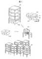
- FIG. 1shows a conceptual configuration of a shelf arrangement system assumed in this embodiment.
- the shelf arrangement systemincludes two or more shelves 100, two or more transfer robots 200 (200a, 200b), and a management terminal 300.
- the shelf 100 in this embodimentis basically four legs, and a space is provided between the shelf legs so that the transfer robot 200 can freely move. That is, a space is provided between the lowermost shelf board and the floor so that the transfer robot 200 can freely move by the shelf legs.
- the transfer robot 200is a kind of so-called automatic guided vehicle.
- the transfer robot 200 according to the present embodimentis attached to a substantially rectangular parallelepiped apparatus main body, a laser distance sensor 210 attached to the front surface in the forward direction, a cargo handling plate 220 attached to the upper surface of the apparatus main body, and left and right side surfaces.
- wheels 230are attached to the mounting method of the wheels 230.
- the mounting method of the wheels 230includes a method of mounting a pair of wheels on the left and right of the apparatus main body, a method of mounting two pairs of wheels on the left and right of the apparatus main body, and a pair of wheels and one auxiliary wheel on the left and right of the apparatus main body.
- Various attachment methodssuch as a method, can be considered.
- the laser distance sensor 210includes a laser light source (for example, a laser diode, LED (light emitting diode)) that emits laser light, a light receiving element that receives laser light from the measurement object, and a measurement object based on the received light. And a calculation unit for calculating the distance. Note that the calculation unit may be arranged on the other device side. In this embodiment, only one laser distance sensor 210 is mounted on the side surface (front surface) facing the traveling direction of the transport robot 200. However, two or more laser distance sensors 210 may be attached to one transport robot 200.
- a laser light sourcefor example, a laser diode, LED (light emitting diode)
- the laser distance sensor 210may be attached to a plurality of side surfaces of the transfer robot 200.
- the laser distance sensors 210are attached to a plurality of side surfaces, the distance from the plurality of side surfaces can be measured at a time with respect to the transport robot 200 without changing the direction.
- the laser distance sensor 210 in this embodimentcan scan the laser beam within a predetermined angular range (for example, 180 °).
- the cargo handling plate 220is a generic term for mechanisms that are driven up and down with respect to the apparatus main body, and includes a plate main body, a first drive unit that drives the plate main body up and down, and a second drive unit that drives the plate main body to rotate. Have. Such a mechanism is known.
- the cargo handling plate 220is used for the operation of lifting the shelf 100 with respect to the apparatus main body that has entered under the shelf 100 and the operation of lowering the raised shelf 100. Due to the presence of the first drive unit, the transfer robot 200 can move while the shelf 100 is lifted with respect to the apparatus main body. Further, the second drive unit can turn the plate main body with respect to the apparatus main body. With this function, the transfer robot 200 can change or adjust the orientation of the shelf 100 with respect to the apparatus main body while the shelf 100 is lifted. This function can be used to adjust the shelf 100 to a predetermined angle with respect to a reference surface such as a wall.
- the transfer robot 200moves straight, and when the wheels 230 rotate in the opposite direction, the transfer robot 200 turns. If the transfer robot 200 is turned while the shelf 100 is lifted, the movement direction of the shelf 100 can be changed and the angle of the shelf 100 can be adjusted. Note that when the transfer robot 200 is turned in the direction opposite to the turning direction while turning the cargo handling plate 220 with respect to the apparatus main body, only the direction of the transfer robot 200 can be changed while the shelf 100 remains stationary. .
- the management terminal 300is a terminal that transmits / receives data to / from each of the plurality of transfer robots 200 via a wireless network.
- the management terminal 300instructs the operation (including movement and turning) of the individual transfer robots 200 and the movement and rotation of the table body in the vertical direction according to the shelf layout.
- FIG. 2shows a shelf transfer system using two transfer robots 200a and 200b.
- a feature of the arrangement of the shelves in the present embodimentis that the side surface of one transfer robot 200a is used instead of a wall.
- the first transfer robot 200atravels while lifting and holding the first shelf 100, and moves to a first shelf installation location where two wall surfaces can be measured by the laser distance sensor 210.
- the first transport robot 200a that has reached the first shelf installation locationhas sensor data (sensor data 404 described later) acquired using the laser distance sensor 210 and a map of the space in which the shelf 100 is placed (map data described later). 400), and adjusts the position and posture of the vehicle so that the vehicle is at a predetermined angle with respect to the front wall and the right wall, and stops when the adjustment is completed. 100 is lowered to the floor.
- the first transfer robot 200aremains stopped in place to provide a reference position for the second transfer robot 200b.
- the second transfer robot 200btravels while lifting and holding the second shelf 100, and moves to the second shelf installation location where the side surface of the first transfer robot 200a can be measured.
- the second transfer robot 200b that has reached the second shelf installation locationis a space in which sensor data (sensor data 404 described later) acquired by the laser distance sensor 210 and the side shape of the first transfer robot 200a are added.
- the own vehicleis collated with a map (map data 400 described later), and the vehicle is at a predetermined angle with respect to the side shape of the first transfer robot 200a that stops the vehicle in front of the vehicle and the right wall surface.
- the first transfer robot 200amoves from the first shelf installation location to the installation location of the third shelf 100. This time, the second transfer robot 200b gives a reference position for the first transfer robot 200a. For this reason, the second transfer robot 200b remains at the second shelf installation location.
- the first transfer robot 200amoves to the third shelf installation location where the second transfer robot 200b can be measured while lifting and holding the third shelf 100.
- the first transport robot 200a that has reached the third shelf installation locationis a space in which sensor data (sensor data 404 described later) acquired by the laser distance sensor 210 and the side surface shape of the second transport robot 200b are added.
- the host vehicleis collated with a map (map data 400 described later), and the host vehicle is set at a predetermined angle with respect to the side surface shape of the second transfer robot 200b that stops the host vehicle in front of the host vehicle and the right wall surface. The position and orientation are adjusted, and when the adjustment is completed, the position is stopped, and the third shelf 100 is lowered on the spot.
- the first and second transfer robots 200a and 200bbasically repeat these operations alternately to align and arrange the plurality of shelves 100 so as to maintain a predetermined angle with the wall surface.
- the management terminal 300is a terminal that is used when an operator plans shelf arrangement and manages the transfer operation of the transfer robot 200 according to the created shelf layout. .
- the management terminal 300according to the present embodiment has a computer (CPU, RAM, ROM, hard disk) as a basic configuration, and provides functions to be described later by executing a program.
- the shelf arrangement planning unit 351creates shelf installation data 420 based on the warehouse map data 400 and the shelf layout data 401.
- the shelf installation data 420includes (1) the order of shelf placement, (2) coordinate values of the placement destination, and (3) shape reference destination (some geometric shape to be referred to determine the position and orientation when placing the shelf) Direction or direction), (4) vehicle allocation data indicating which transfer robot 200 performs the corresponding work, and (5) post-installation operation indicating the destination of the transfer robot after installation.
- the shelf arrangement planning unit 351sets the shelf acquisition destination coordinate data 410 that gives the acquisition location of the shelves 100 to be arranged.
- those coordinate valuescan also be set as the shelf acquisition destination coordinate data 410.
- the transport data creation unit 352creates transport data 430 that defines an operation to be performed by the individual transport robot 200.
- the transport data 430includes various data necessary for transport work, for example, (1) shelf acquisition destination coordinate data 410, (2) shelf placement destination coordinate data 422, (3) shape reference destination data 423, (4) already The coordinates of the installed shelf (installed shelf coordinate value data 440), (5) the coordinates of the transfer robot that refers to the shape (shape reference robot coordinate value data 441), and (6) the post-installation operation data 425 are included.
- Most of the data constituting the transport data 430is created by extracting the data of the corresponding work number from the shelf installation data 420.
- the coordinate values of the already installed shelves 100are the coordinate values of all the shelves 100 installed before the corresponding work number, and the coordinates of the transfer robot 200 that refers to the shape (
- the shape reference robot coordinate value 441)is a coordinate value of the transfer robot 200 installed and stopped before the corresponding work number.
- the transport data 430 created hereis transmitted to the transport robot 200 specified by the dispatch data corresponding to the corresponding work number in the shelf installation data 420.
- the data transmitting / receiving unit 353transmits the transfer data 430 to the transfer robot 200 to be operated next, and receives a notification that the operation is completed from the transfer robot 200 that has completed the operation.
- the data transmission / reception unit 353creates transfer data 430 based on the next work number of the shelf installation data 420 and transmits a transfer command to the corresponding transfer robot 200. To do. It should be noted that the creation of the conveyance data 430 does not necessarily have to be triggered by reception of a work end notification.
- the storage unit(eg, RAM, hard disk) includes (1) a cross-sectional view (map data 400) at a certain height from the floor of the warehouse to be placed on the shelf, (2) shelf layout data 401, (3) shelf Acquisition destination coordinate data 410, (4) shelf installation data 420 created by the shelf arrangement planning unit 351, (5) already installed shelf coordinate value data 440, (6) shape reference robot coordinate value data 441, (7) transfer Data 430, (8) the measurement range of the laser distance sensor 210 (distance sensor measurement range 403) is stored.
- the transfer robot 200is an automatic guided vehicle that automatically runs in the warehouse and automatically installs the shelf 100 to be transferred.
- the laser distance sensor 210 for measuring the distance from the surrounding environmentis attached to the front surface (front side surface) of the apparatus main body constituting the transfer robot 200, and the shelf 100 is raised and lowered on the upper surface of the apparatus main body.
- a cargo handling plate 220 for turning the shelf 100 relative to the apparatus main bodyis attached.
- Wheels 230are attached to the left and right side surfaces of the apparatus main body.
- the transport robot 200moves to the installation location of the shelf 100 to be transported (the location specified by the shelf acquisition destination coordinate data 410), sinks under the shelf 100, and moves to the destination when the shelf 100 is lifted. And the shelf 100 is installed so that it may become a predetermined position and angle with respect to a wall surface.
- a drive mechanism for the cargo handling plate 220, a drive mechanism for the wheels 230, and a computer (CPU, RAM, ROM) for controlling the operation thereofare provided inside the apparatus main body of the transfer robot 200.
- a drive mechanism for the cargo handling plate 220, a drive mechanism for the wheels 230, and a computer (CPU, RAM, ROM) for controlling the operation thereofare provided inside the apparatus main body of the transfer robot 200.
- a drive mechanism for the cargo handling plate 220, a drive mechanism for the wheels 230, and a computer (CPU, RAM, ROM) for controlling the operation thereofare provided inside the apparatus main body of the transfer robot 200.
- a computerCPU, RAM, ROM
- the data transmission / reception unit 251is wirelessly connected to the management terminal 300 through the Internet 600, receives transport data 430 that is information related to shelf transport from the management terminal 300, and notifies the management terminal 300 of the end of transport.
- the sensing unit 252stores data measured by the laser distance sensor 210 as sensor data 404 in a storage unit (RAM).
- the cargo handling unit 253controls a drive mechanism (not shown) to control raising / lowering and / or turning of the cargo handling plate 220.
- the map update unit 254updates the map data 400 stored in the storage unit so as to match the current state.
- the map updating unit 254receives the conveyance data 430 (the existing shelf coordinate value data 440 and the shape reference robot coordinate value data 441) received from the management terminal 300, and the shelf foot shape data 405 stored in the storage unit of the own vehicle. On the basis of the transfer robot shape data 406, the shape data of the shelf legs and the transfer robot are added to the map data 400 stored in the storage unit.
- the drive unit 255is a drive mechanism that drives the wheels 230 to move the transport robot 200.
- the movement control unit 256controls the driving unit 255 to move along the movement route data 431 created based on the conveyance data 430, and the movement robot 200 moves in the warehouse. To control.
- the movement control unit 256controls not only the driving unit 255 but also all operations in the apparatus main body.
- Transfer robot shape data 406which is a sectional view of the transfer robot at the height at which is installed, (4) Transfer data 430 received from the management terminal 300, and (5) A route from the current position to the shelf acquisition position and the shelf installation position Movement path data 431, (6) sensor data 404 representing the distance from the surrounding environment measured using the laser distance sensor 210, and (7) current position data 432 calculated by collation processing between the sensor data 404 and the map data 400 Stored.
- FIG. 4shows the shelf arrangement planning operation executed in the management terminal 300 of this embodiment. This operation is provided through execution of a program by a computer (not shown).
- the shelf arrangement planning unit 351reads the map data 400 and inputs the shelf layout data 401 on the read map data 400 (step S101).
- the shelf arrangement planning unit 351creates instruction data for the transfer robot 200 according to the shelf layout data 401.
- the shelf arrangement planning unit 351sets the shelf acquisition destination coordinate data 410 that is the coordinate value of the place where the shelf 100 is acquired (step S102).
- the shelf arrangement planning unit 351sets the order of installing the shelves 100 (step S103). Furthermore, the shelf arrangement planning unit 351 sets a direction (reference destination) with a shape to be referred to when the shelf 100 is installed (step S104).
- the shelf arrangement planning unit 351sets a direction (reference destination) with a shape to be referred to when the shelf 100 is installed (step S104).
- the first shelf 100is installed at a place where two wall surfaces fall within the measurement range of the laser distance sensor 210 mounted on the transport robot 200.
- the flow of installing the shelf 100 from the back side to the front sidethat is, in a direction gradually approaching from a place away from a point (initial position) where the shelf 100 is taken) Basic.
- FIG. 5shows various layouts used in this embodiment, that is, map data 400, shelf layout data 401, and shelf arrangement order data 402.
- the map data 400is a cross-sectional view (two-dimensional plan view) at a certain height from the floor surface in the warehouse to which the shelf 100 is arranged. The height is the same as the height of the measurement surface of the laser distance sensor 210 mounted on the transfer robot 200.
- the shape of the shelf footis added based on the stop position and posture data transmitted to the management terminal 300 every time the transport robot 200 installs the shelf 100. This addition is executed by the movement control unit 256 described later.
- the map data 400is stored not only in the management terminal 300 but also in all the transport robots 200.
- the shelf layout data 401is a diagram showing how to arrange the shelves 100 on the warehouse map data 400.
- the shelf arrangement order data 402is a diagram showing the arrangement order of the shelves 100 on the shelf layout data 401.
- the arrangement order of the shelves 100is indicated by numbers (for example, 1, 2,..., 24) at the positions where the shelves 100 are arranged, but the shelf arrangement order data 402 is held as a drawing. However, it may be held in a data format like shelf installation data 420 in FIG. 6 to be described later.
- FIG. 6shows data examples of the shelf acquisition destination coordinate data 410 and the shelf installation data 420.
- the shelf acquisition destination coordinate data 410stores coordinate values on the map data 400 of the position (initial position) that is the supply source of the shelf 100.
- the shelf installation data 420includes (1) shelf number data 421, (2) shelf placement destination coordinate data 422, (3) shape reference destination data, (4) dispatch data 424, and (5) after installation, respectively. Operation data 425 is stored.
- the shelf number data 421is a shelf installation destination number written in the shelf arrangement order data 402 (FIG. 5).
- the shelf placement destination coordinate data 422stores the coordinate value (x, y) of the shelf installation destination on the map data 400.
- the shape reference destination data 423stores data indicating the direction or direction to be checked in order to finally determine the installation position of the shelf 100.
- the installation position of the shelf 100is confirmed based on a geometric shape (a wall or a side surface of the other transfer robot 200) that appears around the transfer robot 200 (within the range of the distance sensor measurement range data 403).
- the shelf arrangement planning unit 351is mounted on the transfer robot 200, the map data 400, the shelf installation planned position (shelf layout data 401), the position where the transfer robot 200 other than the transfer robot 200 to be designated is stopped.
- a direction or the likeis determined based on the measurement range (distance sensor measurement range 403) of the laser distance sensor 210, and data specifying the direction is stored in the shape reference destination data 423.
- the directionis determined based on the map data 400 (FIG. 5).
- the direction when the wall enters the front side of the transfer robot 200is indicated by “F”
- the direction when the wall enters the right sideis indicated by “R”
- the direction when the wall enters the left sideis “L”. It shows with.
- the shape reference destination datais used. “5” and “R” are stored.
- a number (robot number) that identifies the transport robot 200 used for transporting the shelf 100is stored.
- “stay”is used when the transport robot 200 used for transporting the shelf 100 is kept on the spot, and “number” that specifies the destination when moving to another place. Is stored.
- the movement destination shelf numberis described in the post-setting operation data 425. However, the coordinate value of the movement destination may be described.
- serial numbers “No.” indicating the execution order of operationsare registered so as not to overlap. However, when a plurality of transfer robots 200 are to be moved simultaneously, the same serial number “No.” A plurality of lines having “” may be registered. For example, a plurality of “6” may be registered such as “1, 2, 3, 4,... 6, 6, 7, 8,... 23, 24”.
- FIG. 7shows basic operations of the transfer robot 200. The following operations are realized by the CPU mounted on the transfer robot 200 by executing the program. Specifically, the movement control unit 256 executes. First, the data transmission / reception unit 251 receives the transport data 430 from the management terminal 300 (step S201).
- the transport data 430includes shelf acquisition destination coordinate data 410, shelf placement destination coordinate data 422, shape reference destination data 423, post-installation operation data 425, already installed shelf coordinate value data 440, and shape reference robot coordinate value data. 441.
- the map update unit 254Based on the existing shelf coordinate value data 440, the shape reference robot coordinate value data 441, the transfer robot shape data 406, and the shelf foot shape data 405 included in the received transfer data 430, the map update unit 254 The shape data of the transport robot 200 and the shape data of the shelf legs are added to the map data 400 stored in its own storage unit. Thereby, the map update part 254 updates the map data 400 to the newest state (step S202). This method can reduce the communication load as compared with the case where the latest map data 400 is received from the management terminal 300 in real time.
- the movement control unit 256moves the transport robot 200 to the coordinate position specified by the shelf acquisition destination coordinate data 410 in order to acquire the shelf 100 to be installed (step S203).
- the movementis realized through the control of the driving unit 255 by the movement control unit 256.
- the transfer robot 200arrives at the coordinate position indicated by the shelf acquisition destination coordinate data 410, the transfer robot 200 performs position / posture matching between the shelf 100 and the own vehicle. A specific method will be described later (FIGS. 13, 14, and 15).
- the movement control unit 256sets the movement path of the transport robot 200 based on the shelf placement destination coordinate data 422 and the current position data 432 received in step S201 (step S204).
- the set travel routeis stored as travel route data 431 in the storage unit of the host vehicle. After setting the movement route, the movement control unit 256 starts moving the transfer robot 200 based on the movement route data 431.
- the movement control unit 256When the traveling guide or the landmark indicating the position is not laid on the floor surface, the movement control unit 256 generally recognizes its own position through the matching process between the sensor data acquired by the laser distance sensor 210 and the map 400. However, if there are few targets in the environment, the necessary information cannot be acquired. That is, the movement control unit 256 cannot use the method described above. In such a case, the movement control unit 256 moves to the vicinity of the destination using the odometry method that calculates the movement distance based on the rotation information of the wheels 230 of the transport robot 200 (step S205).
- the odometry method for obtaining the movement distance and direction by integrating the rotation angle and rotation angular velocity of the left and right wheels 230is caused by errors caused by slipping between the wheels 230 and the floor, the wheel diameter, the size of the transfer robot 200a, and the like.
- the effect of parameter errorsaccumulates with increasing travel distance and cannot reach the exact location.
- position estimationis performed by the odometry method.
- the modeis switched to a position estimation process based on the sensor data 404 and the map data 400 output from the laser distance sensor 210 (step S206). That is, the movement control unit 256 corrects its own position by using the current location calculated by the odometry method, the sensor data 404, and the map 400 as inputs.
- the movement control unit 256moves so that the center position of the transport robot 200 coincides with the destination by collating the sensor data 404 with the map data 400 (step S207).
- the purposeis that the plurality of shelves 100 are aligned and installed at a predetermined angle with respect to the wall surface. Therefore, the movement control unit 256 stores the direction stored in the shape reference destination data 423 received in step S201.
- the direction of the transfer robot 200is changed, and the position and angle of the transfer robot 200 are adjusted by collating the geometric shape measurable in that direction with the map data 400 (step S208).
- the cargo handling plate 220is lowered under the control of the cargo handling unit 253.
- the shelf 100 that has been transported by the transport robot 200is lowered to the floor (step S209).
- the movement control unit 256maintains the stopped state or moves to the next place according to the instruction of the operation data 425 after installation. Thereafter, the movement control unit 256 notifies the management terminal 300 of the completion of installation through the data transmission / reception unit 251.
- FIG. 8shows a case where the first shelf 100 is moved by the transfer robot 200a.
- the transfer robot 200areceives transfer data 430_1 from the management terminal 300 (step S201).
- the transfer data 430_1includes information for the transfer robot 200a to acquire the shelf 100 from the shelf storage location and install it at the placement destination. Specifically, shelf acquisition destination coordinate data 410, shelf placement destination coordinate data 422, shape reference destination data 423, already installed shelf coordinate value data 440, shape reference robot coordinate values 441, and post-installation operation 425 are included.
- the shape reference destination data 423is (F, R).
- the update process of the map data 400is scheduled (step S202), but when the first shelf 100 starts to be transported, the existing shelf 100 and the shape are changed. Since there is no other transfer robot 200b to refer to, the map 400 is not updated.
- (1) to (5) in the figureare views of the operation of the transfer robot 200a in the warehouse as viewed from above.
- the map data 400is a two-dimensional plan view of a warehouse, in which the wall surface and pillars of the warehouse appearing at a certain height from the floor surface are drawn. When the shelf 100 is installed or when the transport robot 200 is stopped, the shape is added to the map data 400.
- the first transfer robot 200ais located at the shelf acquisition destination coordinates (x0, y0), which is the position where the shelf 100 to be installed is supplied. The first transfer robot 200a starts moving from this position.
- the movement control unit 256creates a movement path between the shelf acquisition destination coordinates (x0, y0) and the shelf arrangement destination coordinates (x1, y1), which are movement start positions.
- the movement pathis expressed as, for example, (x0, y0) ⁇ (x0, y1) ⁇ counterclockwise 90 ° rotation ⁇ (x1, y1).
- the first transport robot 200aestimates its own position based on the odometry method, and moves to the vicinity of the shelf placement destination coordinates (x1, y1).
- the movement control unit 256starts from the mode for estimating the self-position based on the odometry method in the distance sensor measurement range data 403.
- the modeis switched to the mode for calculating the self position and the posture by collating the sensor data 404 and the map data 400 acquired in (Step S206). That is, the movement control unit 256 collates the map data 400 and the sensor data 404 in the vicinity of the current location obtained by the odometry method, and corrects the self position and posture.
- the transfer robot 200amoves to the vicinity of the shelf placement destination coordinates (x1, y1) (step S207).
- the movement control unit 256refers to the shape of the wall located in the front specified by “F” in the shape reference destination data 423 included in the conveyance data 430_1, and conveys the parallel to the front wall.
- the position and angle of the robot 200aare corrected (step S208).
- the movement control unit 256refers to the shape of the right wall surface designated by “R” in the shape reference destination data 423 included in the conveyance data 430_1, and conveys the shape so as to be parallel to the shape of the right surface.
- the position and angle of the robot 200aare corrected.
- the transfer robot 200aturns the main body 90 degrees clockwise to correct the position and angle (step S208).
- the turning hereis performed without changing the direction of the shelf 100. Specifically, the main body is rotated clockwise by the pair of wheels 230 while the cargo handling plate 220 is rotated counterclockwise with respect to the main body.
- the cargo handling unit 253lowers the cargo handling plate 220. Thereby, the shelf 100 is lowered to the floor (step S209). Thereafter, the movement control unit 256 transmits the completion of installation to the management terminal 300 through the data transmission / reception unit 251 while stopping on the spot (step S210).
- FIG. 9shows a case where the second shelf 100 is moved by the transfer robot 200b.
- the transfer robot 200breceives transfer data 430_2 from the management terminal 300 (step S201).
- the transport data 430_2includes shelf acquisition destination coordinate data 410, shelf placement destination coordinate data 422, shape reference destination data 423, already installed shelf coordinate value data 440, shape reference robot coordinate value data 441, and post-installation operation data 425. It is.
- the map update unit 254adds the transfer robot shape data 406 and the shelf foot shape data 405 to the positions of the existing shelf coordinates (x1, y1) and the shape reference robot coordinate values (x1, y1) on the map data 400, respectively. (Step S202).
- (1) to (5) in the figureare views of the operation of the transfer robot 200b in the warehouse as viewed from above.
- the transfer robot 200a that has transferred the first shelf 100is stopped at the coordinates (x1, y1) where the first shelf 100 is installed.
- the transport robot 200bis stopped at the position where the second shelf 100 to be installed is supplied (that is, the shelf acquisition destination coordinates (x0, y0)).
- the operations at the time points (2) and (3)are the same as the operations at the time points (2) and (3) described with reference to FIG.
- the transfer robot 200bmoves to the vicinity of the shelf placement destination coordinates (x1, y1) (step S207).
- the movement control unit 256refers to the side shape of the transfer robot 200a that is stopped under the first shelf 100 specified by “1” in the shape reference destination data 423 included in the transfer data 430_2.
- the position and angle of the transfer robot 200bare corrected so as to be parallel to the transfer robot 200a (step S208). That is, the transfer robot 200b adjusts its position and angle based on the geometric shape of the transfer robot 200a whose angle is adjusted with respect to the geometric shape of the wall surface itself in the upward direction in the figure.
- the movement control unit 256recognizes the position and posture of the host vehicle through the matching process between the map data 400 to which the transfer robot shape data 406 and the shelf foot shape data 405 are added and the sensor data 404, and corrects the angle.
- the transfer robot 200brefers to the sensor data 404 and the transfer robot shape data 406, and adjusts the position of the own vehicle so that the center of the transfer robot 200a matches the center of the own vehicle.
- the transfer robot 200brefers to the shape of the right wall surface designated by “R” in the shape reference destination data 423 included in the transfer data 430_2, and the transfer robot 200a is parallel to the right wall surface. Correct the position and angle. Also in this case, the transfer robot 200b turns the main body 90 degrees clockwise to correct the position and angle (step S208).
- the cargo handling unit 253lowers the cargo handling plate 220. Thereby, the shelf 100 is lowered to the floor (step S209). That is, the transfer robot 200b adjusts its position and angle with respect to the geometric shape of the wall surface in the right direction in the drawing.
- the movement control unit 256transmits the completion of installation to the management terminal 300 through the data transmission / reception unit 251 while stopping on the spot (step S210).
- FIG. 10shows a case where the third shelf 100 is moved by the transfer robot 200a.
- the transfer robot 200breceives transfer data 430_1 from the management terminal 300 (step S201).
- (x1, y1) and (x1, y2)are stored as existing shelf coordinate value data 440
- (x1, y2)is stored as shape reference robot coordinate value data 441 in the transport data 430_1.
- the map updating unit 254adds shelf foot shape data 405 to the existing shelf coordinates (x1, y1) and (x1, y1) on the map data 400, and the shape reference robot coordinate values (x1, y1) are added.
- the transfer robot shape data 406is added to the position (step S202).
- the transfer robot 200amoves to the shelf acquisition destination coordinates (x0, y0).
- the subsequent operations at time points (2) to (5)are the same as those described with reference to FIGS. That is, the transfer robot 200a adjusts its position and angle based on the geometric shape of the transfer robot 200b whose angle with respect to the wall surface is indirectly adjusted in the upper direction in the figure. On the other hand, the transfer robot 200a directly adjusts its position and angle in the right direction in the figure based on the geometric shape of the wall surface itself in the direction.
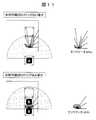
- FIG. 11shows a difference between sensor data 404a when there is no shape reference transfer robot 200 and sensor data 404b when there is a shape reference transfer robot 200.
- the sensor data 404a when there is no shape reference transport robot 200data points acquired in the forward direction of the transport robot 200 appear discretely.
- the reference linecannot be specified, it is difficult to adjust the position and posture of the transfer robot 200. That is, the shelf 100 cannot be aligned with respect to other shelves 100.
- the sensor data 404b when there is the shape reference transfer robot 200data points acquired in the forward direction of the transfer robot 200 are continuous.
- this data point sequenceAs a reference line, it becomes possible to specify the distance and angle between the other transport robot 200 located in front of the host vehicle and the host vehicle. That is, it becomes possible to correct the position and posture of the own vehicle based on the data points corresponding to the other transfer robots 200 stopped in front of the own vehicle.
- FIG. 12shows an operation of the transfer robot 200 immediately after installation of the last shelf 100 in the first row.
- the management terminal 300transmits transfer data 430_6 to the transfer robot 200b in order to instruct transfer of the last shelf 100 in the first row.
- the transport data 430_6is the same as the transport data 430_1 to 430_3 (FIGS. 8 to 10) described above.
- the transfer robot 200bsequentially performs operations from the time point (1) to the time point (5) (not shown) in the same manner as in the case of FIGS. That is, the transfer robot 200b uses the updated map data 400 to move to the vicinity of the shelf placement destination coordinates (x1, y6), and then adjusts the position and orientation with reference to the side shape of the transfer robot 200a. On the floor.
- the transfer robot 200bhas its own position based on the geometric shape of the transfer robot 200a at the position of the number “5” whose angle is indirectly adjusted with respect to the wall surface in the upper direction in the drawing. Adjust the angle. On the other hand, the transfer robot 200b directly adjusts its position and angle based on the geometric shape of the right wall surface in the drawing.
- the movement control unit 256refers to the post-installation operation data 425. In this case, “0” is stored in the post-installation operation data 425 as a number for specifying the destination.
- the coordinates corresponding to the number “0”are shelf acquisition destination coordinates (x0, y0).
- the transfer robot 200bstarts moving to the shelf acquisition destination coordinates (x0, y0).
- the management terminal 300transmits transfer data 430_7 to the transfer robot 200a.
- the transmission of the transfer data 430_7 to the transfer robot 200a by the management terminal 300may be any time after the installation of the shelf 100 by the transfer robot 200b is completed. For example, it may be simultaneously with the start of movement of the transfer robot 200b to the acquisition destination coordinates (x0, y0).
- a mechanism in which the fact is sent from the transfer robot to the management terminal 300 when the arrangement of the shelf 100 on the floor surfaceis completed. Simultaneous movement of the transfer robot 200a and the transfer robot 200b can be realized.
- the transfer data 430_7 received by the transfer robot 200adoes not include information related to shelf installation, and includes only installed shelf coordinate data 440 and post-installation operation data 425. This is because the purpose of movement of the transfer robot 200a is not the transfer of the shelf 100, but is used instead of the right wall when transferring the next shelf 100.
- a time point (7) in FIG. 12represents the moving operation at this time.
- the transfer robot 200 aadds the shelf foot shape data 405 to the map data 400 based on the existing shelf coordinate data 440, the number “1” described in the post-installation operation data 425 using the updated map data 400. Move to the position.
- the coordinates of the number “1”are (x1, y1).
- Time (8)represents this operation.
- the transfer robot 200aestimates the position and posture of the vehicle through a matching process between the sensor data 404 and the map data 400, and corrects the predetermined angle with respect to the front wall and the right wall. To stop.
- the shape reference destination at this timemay be programmed in advance, or may be recorded as the shape reference destination data 423 as in other movements.
- FIG. 13shows the operation of the transport robot 200b when transporting the shelf 100 to the top position of the second row.
- transfer data 430_8is transmitted from the management terminal 300 to the transfer robot 200b.
- (F, 1)is written in the shape reference destination data 423. This data indicates that the shape of the front robot and the shape of the transfer robot 200a located at the number “1” should be referred to.
- the operations at time points (2) to (5)are the same as those shown in FIGS.
- Time (5)'corresponds to an enlarged view of a portion surrounded by a broken line in time (5).
- the transfer robot 200bturns the main body 90 degrees clockwise and recognizes the geometric shape of the transfer robot 200a located at the head of the first row.
- the transfer robot 200bcan adjust the position and posture of the own vehicle so as to maintain a predetermined distance and angle with the transfer robot 200a. That is, the transfer robot 200b directly adjusts its position and angle based on the geometric shape of the wall surface in the upper direction in the drawing, and the transfer robot whose angle is adjusted with respect to the wall surface in the right direction in the drawing. It adjusts its position and angle based on the geometry of 200a.
- the remaining shelves 100 in the second roware arranged in the same procedure as in FIGS.
- the transport robot 200a that transports the shelf 100 to the second position in the second rowis based on the geometric shape of the transport robot 200b whose angle is adjusted based on the geometric shape of the wall surface itself in the upper direction in the figure. Adjust the position and angle.
- the transfer robot 200b that transfers the shelf 100 to the third position in the second rowhas its own position based on the geometric shape of the transfer robot 200a whose angle with respect to the wall surface is indirectly adjusted in the upper direction in the figure. And adjust the angle.
- the transfer robot 200 that newly arranges the shelf 100refers to the sensor data 404 and the transfer robot shape data 406, and the center of the adjacent transfer robot 200 and the center of the own vehicle that are stopped in the upward direction in the figure. Adjust the position of the vehicle to match. Accordingly, even when two transfer robots 200 are used, the plurality of shelves 100 can be aligned with respect to the wall.
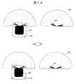
- FIG. 14shows an example of a method for adjusting the position angle between the shelf 100 and the transfer robot 200.
- the size of the shelf 100, the size and position of the shelf legs of the shelf 100, the size of the transfer robot 200, and the relative position of the transfer robot 200 and the laser distance sensor 210are known, when the transfer robot 200 enters the shelf 100
- the relative position and angle of the transfer robot 200 with respect to the shelf 100can be calculated from the distribution of data points of the sensor data 404 measured by the laser distance sensor 210.
- the distribution of the data points of the sensor data 404is not symmetrical in the distance sensor measurement range data 403 spreading like a fan.
- the distribution of the data points of the sensor data 404Is symmetric in the distance sensor measurement range data 403 spreading in a fan shape, and the shelf foot is positioned inside by a specific distance from the end of the distance sensor measurement range data 403.
- the transfer robot 200adjusts the position and angle between the shelf 100 and the own vehicle so that this distribution relationship is obtained. When the distribution of data points satisfies a predetermined relationship, the transfer robot 200 can lift the shelf 100 at the center position directly below the shelf 100.
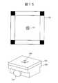
- FIG. 15shows another method for adjusting the position angle between the shelf 100 and the transfer robot 200.
- a shelf bottom marker 101such as a two-dimensional barcode is attached to the shelf bottom of the shelf 100.
- the shelf bottom marker 101is accurately pasted at the center position of the shelf bottom so that the four sides thereof are parallel to the four sides of the shelf 100.
- a camera 240is provided at the center of the upper surface of the cargo handling plate 220. The uppermost surface of the camera 240 is disposed inside the upper surface of the cargo handling plate 220. For this reason, the camera 240 does not hit the shelf bottom even when the cargo handling plate 220 is lifted.
- the shelf bottom marker 101is photographed by the camera 240 of the transfer robot 200 that has entered under the shelf 100. Since the positional relationship between the shelf bottom marker 101 and the shelf 100 is known, the relative position and angle of the transport robot 200 with respect to the shelf 100 can be calculated from the image of the shelf bottom marker 101. If the position angle of the transfer robot 200 is finely adjusted based on this value, the transfer robot 200 can be stopped at the center position directly below the shelf 100 so as to be parallel to the four sides of the shelf 100. In this case, the transport robot 220 stores the captured image in the storage unit, and executes the above-described calculation and adjustment operations by an image processing unit (not shown).
- FIG. 16shows an example of the current coordinate value correction method at the shelf acquisition position.
- the transport robot 200returns to the shelf 100 to be transported at the coordinate position specified by the shelf acquisition destination coordinate data 410, but the shelf 100 is accurate to the shelf acquisition destination coordinate value (x0, y0). It is not always installed in. For this reason, it is necessary to recognize the current coordinate value on the map data 400 after correcting the relative position and angle of the shelf 100 and the transport robot 200 using the method described with reference to FIGS.
- the movement control unit 256compares the sensor data 404 with the wall surface corner portion of the map data 400.
- the current positionis calculated by processing. Even when there is no characteristic geometric shape such as a corner of the wall surface, when the landmark 501 or 502 having a known position or shape is provided on the wall near the shelf acquisition position, for example, the movement control unit 256
- the sensor data 404 from which the landmark is acquiredis compared with the map data 400 to accurately recognize the current position.
- the landmark 501is an example using a plurality of reflectors having different lengths.
- a landmark 502is an example in which three-dimensional (uneven) objects having different depths and widths are installed on a wall surface. It is not practical to install landmarks for self-location estimation in the entire warehouse in consideration of installation costs and reflection on the map data 400. However, if it is only used for a specific location, the work cost is almost negligible.
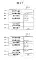
- FIG. 17shows shelf installation data 420 in the case where six shelves 100 are arranged per row using 12 transfer robots 200.
- the transfer robot 200 used for transferremains stopped on the spot. Therefore, when the seventh to twelfth shelves 100 corresponding to the second row are transferred, the transfer robot 200 used for each transfer is stopped in the first row instead of the wall located on the right side. Refer to the shape.
- FIG. 18shows how the shelves 100 are arranged according to the shelf installation data 420.
- the shelves 100are alternately arranged in a row.
- the transfer robot 200 arranged in the rear rowadjusts the positioning and angle based on the geometric shape of the transfer robot 200 stopped in the front row.
- the transfer robot 200 that arranges the leftmost columnmay refer to the shape of the left wall.
- the shelf transfer system of this embodimenthas a poor geometric shape for estimating the position and orientation of the transfer robot 200, such as only the shelf legs are visible within the measurement range of the laser distance sensor 210. Even in the space, the plurality of shelves 100 can be arranged and arranged.
- the transfer robot 200refers to the geometric shape of another transfer robot within the measurement range that is stopped parallel to the wall surface, and is used for adjusting the position and angle of the own vehicle. Thereby, the transfer robot 200 can adjust the position and angle from the viewpoint of two directions, and can automatically align the shelf 100 so as to maintain a predetermined angle with the wall surface.
- the plurality of shelves 100can be arranged and arranged while maintaining a predetermined angle with the wall surface.
- the transfer robot 200since the transfer robot 200 has a function of adjusting the position and angle between the vehicle and the shelf 100, the position and angle accuracy when the shelf 100 is arranged by the transfer robot 200 can be maintained.
- Example 2In the above-described embodiment, a case has been described in which a plurality of shelves 100 are automatically arranged in a warehouse. Here, a method for rearranging the shelves 100 will be described. Even if they are aligned immediately after installation, the arrangement of the shelves 100 may be disturbed during operation. For example, the position and angle of the shelf 100 may be shifted due to a collision with a person who is working, or the position and angle of the shelf 100 may be shifted while the shelf 100 is repeatedly transported.
- FIG. 19shows operations performed by the transfer robot 200 when the shelves 100 are rearranged. 19, parts corresponding to those in FIG. 7 are denoted by the same reference numerals. As can be easily understood from FIG. 19, the basic operation is the same as the operation shown in FIG. However, unlike FIG. 7, the operation of taking the shelf 100 to the shelf supply position (the operation of step S203) is not necessary.
- step S204the movement control unit 256 sets a movement path from the current position of the transport robot 200 to the shelf placement destination coordinates. This is because a reference geometric shape exists around the transfer robot when the shelves are rearranged. In the case of the present embodiment, the movement control unit 256 does not perform movement control by odometry, and moves to the shelf placement destination coordinates as the destination by autonomous movement based on the comparison between the sensor data 404 and the map data 400 (step S207). Next, the movement control unit 256 executes Step S207_2. Step S207_2 is a newly added process, and the movement control unit 256 performs alignment between the shelf 100 and the transfer robot 200, and lifts the shelf 100. For the alignment of the shelf 100 and the transfer robot 200, the method described with reference to FIGS.
- FIG. 20shows an example of the transport data 430 transmitted from the management terminal 300.
- the transfer data 430_11is an example of transfer data 430 transmitted to the first transfer robot 200a
- the transfer data 430_12is an example of transfer data 430 transmitted to the second transfer robot 200b.
- the difference from the first embodimentis that the shelf acquisition destination coordinate data 410 at the time of shelf placement is blank.
- fine adjustment of the arrangement position of the shelf 100 and fine adjustment of the anglecan be performed using the surrounding geometric shape in the same manner as the shelf arrangement except that the shelf 100 is not returned to the specific position. it can. Thereby, it is possible to automate the rearrangement of the shelf 100 in operation.
- the present inventionis not limited to the above-described embodiments, and includes various modifications.
- the above-described embodimentshave been described in detail for easy understanding of the present invention, and it is not always necessary to include all the components described in the embodiments.
- other componentscan be added to each embodiment, some components of each embodiment can be deleted, and some components of each embodiment can be replaced with other components. It can also be replaced.
- the transfer robot 200has a configuration in which the wheels 230 are attached to the left and right of the main body, but the configuration is not limited thereto.
- the transfer robot 200measures the shape of the surroundings of the own vehicle using the laser distance sensor 210, other types of sensors may be mounted.
- each of the above-described configurations, functions, processing units, processing means, and the likemay be realized by hardware by designing a part or all of them with, for example, an integrated circuit.
- Each of the above-described configurations, functions, and the likemay be realized by the processor interpreting and executing a program that realizes each function (that is, in software).
- Informationsuch as programs, tables, and files that realize each function can be stored in a storage device such as a memory, a hard disk, or an SSD (Solid State Drive), or a storage medium such as an IC card, an SD card, or a DVD.
- Control lines and information linesindicate what is considered necessary for the description, and do not represent all control lines and information lines necessary for the product. In practice, it can be considered that almost all components are connected to each other.
- Conveying robot shape data410 ... shelf acquisition destination coordinate data, 420 ... shelf installation data, 421 ... shelf installation number data, 422 ... shelf placement destination coordinate data, 423 ... shape reference data, 424 ... dispatch data, 425 ... Operation data after installation, 430 ... transport data, 431 ... travel route data, 432 ... Current position data, 440 ... Existing shelf coordinate value data, 441 ... Robot coordinate value data for shape reference.
Landscapes
- Engineering & Computer Science (AREA)
- Mechanical Engineering (AREA)
- Aviation & Aerospace Engineering (AREA)
- Radar, Positioning & Navigation (AREA)
- Remote Sensing (AREA)
- Physics & Mathematics (AREA)
- General Physics & Mathematics (AREA)
- Automation & Control Theory (AREA)
- Control Of Position, Course, Altitude, Or Attitude Of Moving Bodies (AREA)
- Manipulator (AREA)
- Warehouses Or Storage Devices (AREA)
Abstract
Description
Translated fromJapanese本発明は、複数台の搬送ロボットを用いて複数の棚を配置する棚配置システム、搬送ロボット及び棚配置方法に関する。The present invention relates to a shelf arrangement system that arranges a plurality of shelves using a plurality of transfer robots, a transfer robot, and a shelf arrangement method.
近年における通販市場の拡大と顧客ニーズの多様化に伴い、物流倉庫で扱う荷物の小口化が進んでいる。これに伴い、物流サービスは多様化・複雑化しており、集品などにかかる作業コストが増加している。一方で労働人口は減少しており、作業の自動化が求められている。作業を自動化する手段の一つとして、荷物(棚に保管する又は棚に保管されている物品)をある地点から別の地点に移動する搬送作業を担う無人搬送車又はAGV(Automatic Guided Vehicle)と呼ばれるものがあり、既に倉庫、工場、港湾などの施設で導入されている。In recent years, with the expansion of the mail order market and diversification of customer needs, the handling of luggage handled in distribution warehouses is becoming smaller. Along with this, logistics services have become diversified and complicated, and work costs for collecting goods have increased. On the other hand, the labor force is declining and work automation is required. As one of the means to automate the work, an automated guided vehicle or AGV (Automatic Guided Vehicle) responsible for transporting goods (stored on shelves or stored on shelves) from one point to another Some of them are already installed in facilities such as warehouses, factories, and harbors.
無人搬送車が、正確・安全・高速に荷物を搬送するためには、棚が整列配置されていること、及び、搬送車が自車位置を正しく認識しながら移動できることの2つが必要である。自車位置を認識する方法の一つとして、搬送車に搭載したレーザ距離センサで周囲の幾何形状を認識し、地図との照合処理により自車位置を把握するものがある。これは、周囲に参考となる幾何形状が存在することが前提となるが、例えば棚の並ぶ倉庫内の走行において、参考となる幾何形状が配置される棚足のみであった場合、自車位置の認識が困難となる場合がある。搬送車に搭載するような小型の距離センサを用いた場合、移動しながら少し離れた場所の棚足を正確に捉えることが出来ないからである。そもそも計測データには誤差が含まれる上に、面積が小さい棚足にレーザ光が必ず到達するとは限らないからである。In order for an automated guided vehicle to transport a load accurately, safely, and at high speed, it is necessary that the shelves are aligned and that the guided vehicle can move while correctly recognizing the position of the vehicle. As one of methods for recognizing the position of the own vehicle, there is a method of recognizing the position of the own vehicle by recognizing a surrounding geometric shape with a laser distance sensor mounted on the transport vehicle and performing a matching process with a map. This is based on the premise that there is a reference geometric shape in the surroundings.For example, in traveling in a warehouse where shelves are lined up, if the reference geometric shape is only placed, the vehicle position May be difficult to recognize. This is because when a small distance sensor mounted on a transport vehicle is used, it is not possible to accurately grasp a shelf foot at a slightly separated place while moving. In the first place, the measurement data includes an error and the laser beam does not always reach the shelf with a small area.
無人搬送車に関する先行技術を記載する文献には、例えば特許文献1及び2がある。特許文献1には、「先に取合位置9に走行停止させる無人搬送車AGV1の車体の側面に反射板20を設ける。あとから取合位置9に走行停止させる無人搬送車AGV2の側面に反射板20を検出する光電センサからなる第2停止用センサ16を設ける。あとから到着する無人搬送車AGV2は、先に停止済の無人搬送車AGV1の反射板20を検出して走行停止する。」(要約書参照)ことが記載されている。There are, for example,
また、特許文献2には、「搬送車3は、搬送車本体3aと、搬送車本体3aに設けられる測距センサ50と、地図データDB42と、近似線算出部47と、位置算出部46と、を備えている。搬送車本体3aは、第1エリアと、前記第1エリア以外の第2エリアと、を含む経路を走行する。近似線算出部47は、第1エリアAでは、測距センサ50が測定した複数の測定データのうち所定の閾値以上の光の強度を有する測定データの集合に基づいて近似線を算出し、第2エリアBでは、複数の測定データの集合に基づいて近似線を算出する。位置算出部46は、近似線と地図データとを照合することで、搬送車本体3aの位置を算出する。」(要約書参照)ことが記載されている。
要するに、特許文献1は、平行に走行する2台の無人搬送車のうち先に停車した無人搬送車に取り付けられている反射板を基準に、後続する無人搬送車の停止位置を決定する技術を記載し、特許文献2は、測定データの集合に基づいて自車の位置を算出する技術を記載するものであり、無人搬送車を用いて複数の棚を整列配置することは想定されていない。そもそも、倉庫内を移動する無人搬送車に関する既存のシステムでは、棚は設置対象ではなく基準位置を与える存在である(棚は基準位置として設置済みである)。仮に、特許文献1及び2に記載の技術を棚の搬送に応用したとしても、複数の棚(又は複数の無人搬送車)の間の角度を所定の角度に調整する仕組みが存在しないため、複数の棚を整列設置することはできない。In short,
本発明は、棚を設置する空間に位置や向きの推定に必要な幾何形状が乏しい場合でも、壁面と所定の角度を保つように棚を自動的に整列して配置できる技術を提供する。The present invention provides a technique capable of automatically arranging and arranging shelves so as to maintain a predetermined angle with a wall surface even when the geometrical shape necessary for estimating the position and orientation is insufficient in the space where the shelves are installed.
上記課題を解決するために、本発明は、例えば特許請求の範囲に記載の構成を採用する。本明細書は上記課題を解決する手段を複数含んでいるが、その一例を挙げるならば、「周囲形状を測定するセンサと、地図データを記憶する記憶部とを有し、棚を搬送する少なくとも2台の搬送ロボットと、前記搬送ロボットの動作を規定する搬送データを送信する管理端末とを有し、前記搬送ロボットは、前記搬送データで指定された位置に移動した後、前記搬送データで指定された方向を前記センサで測定し、壁面に対する角度が調整されている他の搬送ロボットの幾何形状に基づいて前記棚の位置及び角度を調整する棚配置システム」である。In order to solve the above-mentioned problems, the present invention adopts, for example, the configurations described in the claims. The present specification includes a plurality of means for solving the above-mentioned problems. To give an example, “at least a sensor having a sensor for measuring the surrounding shape and a storage unit for storing map data and transporting a shelf” Two transfer robots and a management terminal that transmits transfer data that defines the operation of the transfer robot, and the transfer robot moves to a position specified by the transfer data and then is specified by the transfer data A shelf placement system that measures the measured direction with the sensor and adjusts the position and angle of the shelf based on the geometry of another transfer robot whose angle to the wall surface is adjusted.
本発明によれば、棚を設置する空間に位置や向きの推定に必要な幾何形状が乏しい場合でも、壁面と所定の角度を保つように棚を自動的に整列して配置することができる。前述した以外の課題、構成及び効果は、以下の実施の形態の説明により明らかにされる。According to the present invention, the shelf can be automatically aligned and arranged so as to maintain a predetermined angle with the wall surface even when the geometrical shape necessary for estimating the position and orientation is insufficient in the space where the shelf is installed. Problems, configurations, and effects other than those described above will become apparent from the following description of embodiments.
以下、図面に基づいて、本発明の実施の形態を説明する。なお、本発明の実施の態様は、後述する実施例に限定されるものではなく、その技術思想の範囲において、種々の変形が可能である。Hereinafter, embodiments of the present invention will be described with reference to the drawings. The embodiment of the present invention is not limited to the examples described later, and various modifications are possible within the scope of the technical idea.
(1)実施例1
本実施例では、物流倉庫の利用に先立って(倉庫内に何も設置されていない状態で)、複数の搬送ロボットを用いて壁面に平行になるように棚を自動的に整列配置する棚配置システムについて説明する。(1) Example 1
In this embodiment, prior to the use of a distribution warehouse (when nothing is installed in the warehouse), a shelf arrangement that automatically arranges and arranges the shelves so as to be parallel to the wall surface using a plurality of transfer robots. The system will be described.
(1-1)システムの全体構成
図1に、本実施例で想定する棚配置システムの概念構成を示す。棚配置システムは、2台以上の棚100と、2台以上の搬送ロボット200(200a、200b)と、管理端末300とで構成される。本実施例における棚100は、基本的に4本脚であり、棚足と棚足の間には搬送ロボット200が自由に移動できるだけの空間が設けられている。すなわち、最下段の棚板と床面との間には棚足によって、搬送ロボット200が自由に移動できるだけの空間が設けられている。(1-1) Overall Configuration of System FIG. 1 shows a conceptual configuration of a shelf arrangement system assumed in this embodiment. The shelf arrangement system includes two or
搬送ロボット200は、いわゆる無人搬送車の一種である。本実施例の搬送ロボット200は、概略直方体形状の装置本体と、その前進方向前面に取り付けられたレーザ距離センサ210と、装置本体の上面に取り付けられた荷役プレート220と、左右両側面に取り付けられた車輪230とで構成される。なお、車輪230の取付方法には、装置本体の左右に一対の車輪を取り付ける方法、装置本体の左右に二対の車輪を取り付ける方法、装置本体の左右に一対の車輪と一つの補助輪を取り付ける方法等、様々な取付方法が考えられる。The
レーザ距離センサ210は、レーザ光を照射するレーザ光源(例えばレーザダイオード、LED(light emitting diode))と、測定対象物からのレーザ光を受光する受光素子と、受光した光に基づいて測定対象物の方向と距離を算出する演算部とで構成される。なお、演算部は他のデバイスの側に配置される場合もある。本実施例の場合、レーザ距離センサ210は、搬送ロボット200の進行方向に面した側面(前面)に1つだけ搭載されている。もっとも、レーザ距離センサ210は、1台の搬送ロボット200に対して2つ以上取り付けられていても良い。同一面に2つ以上のレーザ距離センサ210を設置する場合、上下に設置すれば異なる高さにおける距離を計測することが可能となり、左右に設置すれば一度に広範囲の距離を計測することができる。また、レーザ距離センサ210は、搬送ロボット200の複数の側面に取り付けられていても良い。複数の側面にレーザ距離センサ210が取り付けられている場合、方向転換しなくても搬送ロボット200に対して複数の側面からの距離を一度に測定することができる。なお、後述するように、本実施例におけるレーザ距離センサ210は、所定角範囲(例えば180°)内でレーザ光を走査できる。The
荷役プレート220は、装置本体に対して上下に駆動される機構の総称であり、プレート本体とプレート本体を上下に駆動する第1の駆動部と、プレート本体を旋回駆動する第2の駆動部を有している。このような機構は既知である。荷役プレート220は、棚100の下に潜り込んだ装置本体に対して棚100の持ち上げる動作や持ち上げた棚100を下ろす動作に使用される。第1の駆動部の存在により、搬送ロボット200は、棚100を装置本体に対して持ち上げたまま移動することができる。また、第2の駆動部は、プレート本体を装置本体に対して旋回させることができる。この機能により、搬送ロボット200は、棚100を持ち上げた状態で装置本体に対して棚100の向きを変更又は調整することができる。この機能は、棚100を壁などの基準面に対して所定の角度に調整するのに用いることができる。The
装置本体の左右側面の車輪230が同一方向に回転することで搬送ロボット200は直進し、逆方向に回転することで搬送ロボット200は旋回する。棚100を持ち上げた状態で搬送ロボット200を旋回させれば、棚100の移動方向の変更や棚100の角度調整を行うことができる。なお、荷役プレート220を装置本体に対して旋回させながら、その旋回方向とは逆向きに搬送ロボット200を旋回させると、棚100は静止状態のまま搬送ロボット200の向きだけを変更させることができる。When the
管理端末300は、複数の搬送ロボット200のそれぞれとの間で、無線ネットワークを介してデータを送受信する端末である。管理端末300は、棚の配置レイアウトに従って、個々の搬送ロボット200の動作(移動や旋回を含む。)、テーブル本体の上下方向への移動と回転)を指示する。The
(1-2)棚を配置する動作イメージ
まず、図2に基づいて、本実施例における棚配置のイメージを説明する。図2は、2台の搬送ロボット200a及び200bを用いる棚搬送システムについて表している。本実施例における棚の配列の特徴は、一方の搬送ロボット200aの側面を壁の代わりに使用する点である。(1-2) Image of Arranging Shelf First, an image of shelf arrangement in the present embodiment will be described with reference to FIG. FIG. 2 shows a shelf transfer system using two
まず、第1の搬送ロボット200aは、1つ目の棚100を持ち上げて保持したまま走行し、レーザ距離センサ210によって2つの壁面を計測可能な第1の棚設置場所まで移動する。第1の棚設置場所に達した第1の搬送ロボット200aは、レーザ距離センサ210を用いて取得したセンサデータ(後述するセンサデータ404)と、棚100を配置する空間の地図(後述する地図データ400)とを照合し、自車が正面の壁面と右側の壁面に対して所定の角度となるように自車位置及び姿勢を調整し、調整が終了した時点で停止し、1つ目の棚100を床面に降ろす。本実施例の場合、第1の搬送ロボット200aは、第2の搬送ロボット200bに対する基準位置を与えるため、その場に停止したままである。First, the
次のステップにおいて、第2の搬送ロボット200bは、2つ目の棚100を持ち上げて保持したまま走行し、第1の搬送ロボット200aの側面を計測可能な第2の棚設置場所まで移動する。第2の棚設置場所に達した第2の搬送ロボット200bは、レーザ距離センサ210で取得したセンサデータ(後述するセンサデータ404)と、第1の搬送ロボット200aの側面形状が追記された空間の地図(後述する地図データ400)とを照合し、自車を自車の正面に停止している第1の搬送ロボット200aの側面形状と右側の壁面に対して所定の角度となるように自車位置及び姿勢を調整し、調整が完了すると、その場に2つ目の棚100を降ろす。2つ目の棚100の設置が終わると、第1の搬送ロボット200aは、第1の棚設置場所から3つ目の棚100の設置位置に移動する。今度は、第2の搬送ロボット200bが第1の搬送ロボット200aに対する基準位置を与える。このため、第2の搬送ロボット200bは、第2の棚設置場所に留まる。In the next step, the
更に次のステップでは、第1の搬送ロボット200aは3つ目の棚100を持ち上げて保持したまま、第2の搬送ロボット200bを計測可能な第3の棚設置場所まで移動する。第3の棚設置場所に達した第1の搬送ロボット200aは、レーザ距離センサ210で取得したセンサデータ(後述するセンサデータ404)と、第2の搬送ロボット200bの側面形状が追記された空間の地図(後述する地図データ400)とを照合し、自車を自車の正面に停止している第2の搬送ロボット200bの側面形状と右側の壁面に対して所定の角度となるように自車位置及び姿勢を調整し、調整が終了した時点で停止し、その場に3つ目の棚100を降ろす。In the next step, the
第1及び第2の搬送ロボット200a及び200bは、基本的にこれらの動作を交互に繰り返すことにより、壁面と所定の角度を保つように複数の棚100を整列配置する。The first and
(1-3)搬送ロボット及び管理端末の機能ブロック構成
ここでは、図3を使用し、本実施例に係る搬送ロボット200と管理端末300の機能ブロック構成を説明する。(1-3) Functional Block Configurations of Transfer Robot and Management Terminal Here, the functional block configurations of the
(1-3-1)管理端末の機能ブロック
管理端末300は、オペレータが棚配置をプランニングする際に使用されると共に、作成された棚のレイアウトに従って搬送ロボット200の搬送動作を管理する端末である。本実施例の管理端末300は、コンピュータ(CPU、RAM、ROM、ハードディスク)を基本構成とし、後述する機能をプログラムの実行を通じて提供する。棚配置プランニング部351は、倉庫の地図データ400と棚レイアウトデータ401とに基づいて、棚設置データ420を作成する。棚設置データ420は、(1)棚配置の順番、(2)配置先の座標値、(3)形状参照先(棚の配置時に位置や姿勢を決定するために参照する何らかの幾何形状が存在する方角又は方向)、(4)どの搬送ロボット200が該当する作業を担うかを示す配車データ、(5)設置後の搬送ロボットの移動先を示す設置後動作を含む。(1-3-1) Functional Block of Management Terminal The
また、棚配置プランニング部351は、配列する棚100の取得場所を与える棚取得先座標データ410を設定する。本実施例の場合、棚取得先座標データ410は1つである。すなわち、棚100が搬送ロボット200によって搬送された後は、別の棚100が同じ場所に人手等によって配置されるものとする。ただし、複数の棚100の配列前の位置を特定する座標が既知の場合には、それらの座標値を棚取得先座標データ410として設定することもできる。Also, the shelf
搬送データ作成部352は、個別の搬送ロボット200が実行すべき動作を規定する搬送データ430を作成する。搬送データ430には、搬送作業に必要となる各種のデータ、例えば(1)棚取得先座標データ410、(2)棚配置先座標データ422、(3)形状参照先データ423、(4)既に設置済みの棚の座標(既設置棚座標値データ440)、(5)形状を参照する搬送ロボットの座標(形状参照用ロボット座標値データ441)、(6)設置後動作データ425が含まれる。搬送データ430を構成するデータのほとんどは、棚設置データ420から該当する作業番号のデータを抽出することにより作成される。The transport
既に設置済みの棚100の座標値(記設置棚座標値データ440)は、該当する作業番号より前に設置された全ての棚100の座標値であり、形状を参照する搬送ロボット200の座標(形状参照用ロボット座標値441)は、該当する作業番号より前に設置され停止している搬送ロボット200の座標値である。ここで作成した搬送データ430は、棚設置データ420のうち該当する作業番号に対応する配車データで特定される搬送ロボット200に対して送信される。The coordinate values of the already installed shelves 100 (recorded shelf coordinate value data 440) are the coordinate values of all the
データ送受信部353は、次に作業する搬送ロボット200に対して搬送データ430を送信すると共に、作業を終えた搬送ロボット200から作業が終了した旨の通知を受信する。作業の終了通知を搬送ロボット200から受信した場合、データ送受信部353は、棚設置データ420の次の作業番号に基づいて搬送データ430を作成し、搬送指令を該当する搬送ロボット200に対して送信する。なお、搬送データ430の作成は、必ずしも作業の終了通知の受信をトリガーとして開始しなくても良い。The data transmitting / receiving
記憶部(例えばRAM、ハードディスク)には、(1)棚配置の対象となる倉庫の床面からのある高さの断面図(地図データ400)、(2)棚レイアウトデータ401、(3)棚取得先座標データ410、(4)棚配置プランニング部351で作成された棚設置データ420、(5)既設置棚座標値データ440、(6)形状参照用ロボット座標値データ441、(7)搬送データ430、(8)レーザ距離センサ210の測定範囲(距離センサ測定範囲403)が格納されている。The storage unit (eg, RAM, hard disk) includes (1) a cross-sectional view (map data 400) at a certain height from the floor of the warehouse to be placed on the shelf, (2)
(1-3-2)搬送ロボットの機能ブロック
搬送ロボット200は、倉庫内を自走して搬送対象である棚100を自動的に設置する無人搬送車である。前述したように、搬送ロボット200を構成する装置本体の前面(前方側面)には周囲環境との距離を計測するレーザ距離センサ210が取り付けられると共に、装置本体の上面には棚100を上げ下げすると共に棚100を装置本体に対して旋回させる荷役プレート220が取り付けられている。また、装置本体の左右側面には車輪230が取り付けられている。(1-3-2) Function Block of Transfer Robot The
搬送ロボット200は、搬送対象である棚100の設置場所(棚取得先座標データ410で指定される場所)まで移動して棚100の下に潜り込み、棚100を持ち上げるとその状態で目的地まで移動し、壁面に対して所定の位置及び角度になるように棚100を設置する。搬送ロボット200の装置本体の内部には、荷役プレート220の駆動機構、車輪230の駆動機構、それらの動作を制御するコンピュータ(CPU、RAM、ROM)が備えられている。後述する機能は、コンピュータによるプログラムの実行を通じて提供される。The
データ送受信部251は、インターネット600を通じて管理端末300と無線接続されており、棚搬送に関する情報である搬送データ430を管理端末300から受信すると共に、搬送の終了を管理端末300に通知する。センシング部252は、レーザ距離センサ210で計測したデータをセンサデータ404として記憶部(RAM)に格納する。荷役部253は、不図示の駆動機構を制御して、荷役プレート220の上げ下げ及び/又は旋回を制御する。地図更新部254は、記憶部に格納されている地図データ400を現在の状態に合うよう更新する。地図更新部254は、管理端末300から受信した搬送データ430(既設置棚座標値データ440、形状参照用ロボット座標値データ441)と、自車の記憶部に格納されている棚足形状データ405及び搬送ロボット形状データ406とに基づいて、記憶部に格納されている地図データ400に対して棚足と搬送ロボットの形状データを追記する。The data transmission /
駆動部255は、車輪230を駆動して搬送ロボット200を移動させる駆動機構である。移動制御部256は、管理端末300から指示を受信した後、搬送データ430に基づいて作成した移動経路データ431に沿って移動するように駆動部255を制御し、搬送ロボット200の倉庫内における移動を制御する。本実施例の場合、移動制御部256は、駆動部255だけでなく装置本体内の全ての動作を制御する。The
記憶部(例えばRAM)には、(1)地図データ400、(2)レーザ距離センサ210が設置された高さにおける棚足の断面図である棚足形状データ405、(3)レーザ距離センサ210が設置された高さにおける搬送ロボットの断面図である搬送ロボット形状データ406、(4)管理端末300より受信した搬送データ430、(5)現在地から棚取得位置や棚設置位置までの経路を示す移動経路データ431、(6)レーザ距離センサ210を用いて測定した周囲環境との距離を表すセンサデータ404、(7)センサデータ404と地図データ400との照合処理により算出した現在位置データ432が格納される。In the storage unit (for example, RAM), (1)
(1-4)管理端末における棚配置プランニング動作
図4に、本実施例の管理端末300で実行される棚配置プランニング動作を示す。この動作は、不図示のコンピュータによるプログラムの実行を通じて提供される。まず、棚配置プランニング部351は、地図データ400を読み込むと共に、読み込んだ地図データ400の上に棚レイアウトデータ401を入力する(ステップS101)。棚配置プランニング部351は、この棚レイアウトデータ401に従って搬送ロボット200に対する指示データを作成する。指示データの作成には、搬送ロボット200が搬送対象となる棚100を取りに行く場所が必要である。そこで、棚配置プランニング部351は、棚100を取得する場所の座標値である棚取得先座標データ410を設定する(ステップS102)。(1-4) Shelf Arrangement Planning Operation in the Management Terminal FIG. 4 shows the shelf arrangement planning operation executed in the
次に、棚配置プランニング部351は、棚100を設置する順番を設定する(ステップS103)。更に、棚配置プランニング部351は、棚100を設置する際に参照する形状がある方向(参照先)を設定する(ステップS104)。複数の棚100を壁面に対して所定の角度を保つように設置(配列)するには、まず初めに、壁面の認識が可能な場所に1つ目の棚100を設置する必要がある。1つ目の棚100は、搬送ロボット200に搭載したレーザ距離センサ210の計測範囲に2つの壁面が入る場所に設置する。また、棚100の設置が容易となるように、奥側から手前側に(すなわち、棚100を取りに行く地点(初期位置)から離れた場所から徐々に近づく方向に棚100を設置する流れを基本とする。Next, the shelf
(1-5)各種レイアウト
図5に、本実施例で使用する各種レイアウト、すなわち地図データ400、棚レイアウトデータ401、棚配置順データ402を示す。地図データ400は、棚100の配置対象である倉庫内の床面からのある高さにおける断面図(2次元平面図)である。その高さは、搬送ロボット200に搭載されるレーザ距離センサ210の計測面の高さと同じである。地図データ400上には、搬送ロボット200が棚100を設置する毎に管理端末300に送信する停止位置および姿勢データに基づいて棚足の形状が追加される。この追加は、後述する移動制御部256によって実行される。地図データ400は、図3に示すように、管理端末300だけでなく、全ての搬送ロボット200に格納されている。(1-5) Various Layouts FIG. 5 shows various layouts used in this embodiment, that is,
棚レイアウトデータ401は、倉庫の地図データ400の上にどのように棚100を配置するか示す図である。棚配置順データ402は、棚レイアウトデータ401上における棚100の配置順序を示す図である。図5の棚配置順データ402には、棚100を配置する位置に棚100の配置順序を数字(例えば1、2、…24)で示しているが、棚配置順データ402は図面として保持されている必要はなく、後述する図6の棚設置データ420のようにデータ形式で保持されていても構わない。The
(1-6)棚取得先座標データ及び棚設置データ
図6に、棚取得先座標データ410と棚設置データ420のデータ例を示す。棚取得先座標データ410には、棚100の供給元となる位置(初期位置)の地図データ400上での座標値が格納される。棚設置データ420には、配置作業順にそれぞれ、(1)棚番号データ421、(2)棚配置先座標データ422、(3)形状参照先データ、(4)配車データ424、(5)設置後動作データ425が格納されている。(1-6) Shelf Acquisition Destination Coordinate Data and Shelf Installation Data FIG. 6 shows data examples of the shelf acquisition destination coordinate
棚番号データ421は、棚配置順データ402(図5)に記されている棚設置先の番号のことである。棚配置先座標データ422には、地図データ400上における棚設置先の座標値(x, y)が格納される。形状参照先データ423には、棚100の設置位置を最終的に決定するために確認する方向又は方角を示すデータが格納される。棚100の設置位置は、搬送ロボット200の周囲(距離センサ測定範囲データ403の範囲内)に出現する幾何形状(壁や他の搬送ロボット200の側面)を基準に確認される。The
ここで、棚配置プランニング部351は、地図データ400、棚設置予定位置(棚レイアウトデータ401)、指示対象とする搬送ロボット200以外の搬送ロボット200が停止している位置、搬送ロボット200に搭載するレーザ距離センサ210の計測範囲(距離センサ測定範囲403)に基づいて方向等を定め、当該方向を特定するデータを形状参照先データ423に格納する。方向は、地図データ400(図5)を基準に定める。Here, the shelf
例えば搬送ロボット200の前面側に壁が入る場合の方向は「F」で示し、右面側に壁が入る場合の方向は「R」で示し、左面側に壁が入る場合の方向は「L」で示す。例えば他の搬送ロボット200が棚配置順データ402(図5)の「5」の場所に停止している場合において、搬送ロボット200が6つ目の棚100を搬送するとき、形状参照先データとして「5」と「R」が格納される。For example, the direction when the wall enters the front side of the
配車データ424には、棚100の搬送に使用する搬送ロボット200を特定する番号(ロボット番号)が格納される。設置後動作データ425には、棚100の設置後に、その搬送に使用した搬送ロボット200をその場に留める場合は「stay」が、別の場所に移動する場合は移動先を特定する「番号」が格納される。なお、図6では、移動先の棚の番号を設定後動作データ425に記載しているが、移動先の座標値を記載しても良い。In the
なお、図6の説明では、動作の実行順序を示す通し番号「No.」が重複しないように登録されているが、複数台の搬送ロボット200を同時に動かしたい場合には、同じ通し番号「No.」を有する行を複数登録してもよい。例えば「1, 2, 3, 4, …6, 6, 7,8, …23, 24」というように「6」を複数登録してもよい。In the description of FIG. 6, serial numbers “No.” indicating the execution order of operations are registered so as not to overlap. However, when a plurality of
(1-7)搬送ロボットにおいて実行される動作
図7に、搬送ロボット200の基本動作を示す。以下の動作は、搬送ロボット200に搭載されたCPUがプログラムの実行を通じて実現する。具体的には、移動制御部256が実行する。まず、データ送受信部251は、管理端末300から搬送データ430を受信する(ステップS201)。搬送データ430には、棚取得先座標データ410と、棚配置先座標データ422、形状参照先データ423、設置後動作データ425と、既設置棚座標値データ440と、形状参照用ロボット座標値データ441とが含まれる。(1-7) Operations Performed in Transfer Robot FIG. 7 shows basic operations of the
地図更新部254は、受信した搬送データ430に含まれる既設置棚座標値データ440と、形状参照用ロボット座標値データ441と、搬送ロボット形状データ406と、棚足形状データ405とに基づいて、自身の記憶部に格納されている地図データ400に搬送ロボット200の形状データと棚足の形状データを追加する。これにより、地図更新部254は地図データ400を最新の状態に更新する(ステップS202)。この方式は、最新の地図データ400を管理端末300からリアルタイムで受信する場合に比して通信負荷を低減することができる。Based on the existing shelf coordinate
次に、移動制御部256は、設置対象とする棚100を取得するために、棚取得先座標データ410で指定された座標位置まで搬送ロボット200を移動させる(ステップS203)。ここでの移動は、移動制御部256による駆動部255の制御を通じて実現される。搬送ロボット200は、棚取得先座標データ410で示される座標位置に到着すると、棚100と自車との位置/姿勢合わせを行う。具体的な方法については後述する(図13、図14、図15)。Next, the
移動制御部256は、ステップS201で受信した棚配置先座標データ422と現在位置データ432とに基づいて搬送ロボット200の移動経路を設定する(ステップS204)。設定された移動経路は移動経路データ431として自車の記憶部に格納される。移動経路の設定後、移動制御部256は、移動経路データ431に基づいて搬送ロボット200の移動を開始する。The
床面に走行ガイドや位置を示すランドマークが敷設されていない場合、移動制御部256は、一般に、レーザ距離センサ210で取得したセンサデータと地図400との照合処理を通じて自己位置を認識する。しかし、環境内に目標となる物がほとんど無い場合、必要とする情報を取得できない。すなわち、移動制御部256は、前述した方法を用いることができない。このような場合、移動制御部256は、搬送ロボット200の車輪230の回転情報に基づいて移動距離を算出するオドメトリ法を用い、目的地の近傍まで移動する(ステップS205)。When the traveling guide or the landmark indicating the position is not laid on the floor surface, the
左右の車輪230の回転角と回転角速度を積算することで移動距離と方向を求めるオドメトリ法は、車輪230と床面との滑りにより生じる誤差、車輪径や搬送ロボット200aの大きさ等に起因するパラメータ誤差の影響が移動距離の増加に伴って累積し、正確な場所に到達することができない。周囲に参考となる幾何形状がない場所においては、オドメトリ法による位置推定を行うが、本実施例の場合、目的地の近傍には、壁面に加えて他の搬送ロボット200の幾何形状等が存在する。そこで、移動制御部256は、目的地の近傍に到達すると、レーザ距離センサ210から出力されるセンサデータ404と地図データ400とによる位置推定処理にモードを切り替える(ステップS206)。すなわち、移動制御部256は、オドメトリ法により算出した現在地と、センサデータ404と、地図400とを入力として自己位置を補正する。The odometry method for obtaining the movement distance and direction by integrating the rotation angle and rotation angular velocity of the left and
移動制御部256は、センサデータ404と地図データ400との照合により、搬送ロボット200の中心位置が目的地に一致するように移動する(ステップS207)。本実施例では、複数の棚100が壁面に対して所定の角度で整列設置することを目的とするため、移動制御部256は、ステップS201で受信した形状参照先データ423に格納されている方向に搬送ロボット200の向きを変更し、その方向で計測可能な幾何形状と地図データ400との照合により、搬送ロボット200の位置と角度を調整する(ステップS208)。ステップS208で位置と角度の調整が終了すると、荷役部253の制御の下、荷役プレート220を降下させる。これにより、搬送ロボット200によって搬送されてきた棚100は床面に降ろされる(ステップS209)。棚100を床面に降ろすと、移動制御部256は、設置後動作データ425の指示に従い、その場に停止した状態を維持するか又は次の場所に移動する。この後、移動制御部256は、データ送受信部251を通じて管理端末300に設置完了を通知する。The
(1-8)搬送動作
以下では、2台の搬送ロボット200を用いて棚100を搬送する場合の動作を説明する。以下の説明では、2台の搬送ロボット200のうち一方を搬送ロボット200aとし、他方を搬送ロボット200bとする。(1-8) Transport Operation Hereinafter, the operation when transporting the
図8に、1つ目の棚100を搬送ロボット200aで移動する場合を示す。まず、搬送ロボット200aは、管理端末300より搬送データ430_1を受信する(ステップS201)。搬送データ430_1には、搬送ロボット200aが棚100を棚置場から取得して配置先に設置するための情報が含まれる。具体的には、棚取得先座標データ410、棚配置先座標データ422、形状参照先データ423、既設置棚座標値データ440、形状参照用ロボット座標値441、設置後動作425が含まれる。1つ目の棚100の配置時には、形状の参照に使用可能な他の搬送ロボット200は未だ倉庫内に存在しない。このため、地図データ400上で正面と右面に位置する2つの壁面が形状参照先に指定される。このため、形状参照先データ423は(F,R)である。FIG. 8 shows a case where the
前述の説明によれば、この時点で、地図データ400の更新処理の実行が予定されている(ステップS202)が、1つ目の棚100の搬送を開始する時点では、既設の棚100や形状を参照すべき他の搬送ロボット200bが存在しないため、地図400の更新はしない。図中の(1)~(5)は、倉庫内における搬送ロボット200aの動作を上面から眺めた図である。地図データ400は、倉庫の2次元平面図であり、床面から一定の高さに現れる倉庫の壁面や柱等が描かれる。棚100の設置後や搬送ロボット200が停止した場合には、その形状が、地図データ400上に追加される。According to the above description, at this point in time, the update process of the
時点(1)において、第1の搬送ロボット200aは、設置する棚100が供給される位置である棚取得先座標(x0, y0)に位置している。第1の搬送ロボット200aは、この位置から移動を開始する。時点(2)において、移動制御部256は、移動開始位置である棚取得先座標(x0, y0)と棚配置先座標(x1, y1)との間で移動経路を作成する。移動経路は、例えば(x0, y0) → (x0, y1) → 反時計回り90°回転 → (x1, y1)と表される。本実施例の場合、第1の搬送ロボット200aは、オドメトリ法に基づいて自己位置を推定し、棚配置先座標(x1, y1)の近傍まで移動する。At time (1), the
時点(3)において(棚配置先座標(x1, y1)の近傍に到達した時点で)、移動制御部256は、オドメトリ法に基づいて自己位置を推定するモードから、距離センサ測定範囲データ403内で取得したセンサデータ404と地図データ400との照合によって自己位置と姿勢を算出するモードに切り替わる(ステップS206)。すなわち、移動制御部256は、オドメトリ法で求めた現在地の近傍において地図データ400とセンサデータ404を照合し、自己位置と姿勢を補正する。At the time point (3) (when reaching the vicinity of the shelf placement destination coordinates (x1, y1)), the
時点(4)において、搬送ロボット200aは、棚配置先座標(x1, y1)の近傍まで移動する(ステップS207)。ここで、移動制御部256は、搬送データ430_1に含まれる形状参照先データ423のうち「F」で指定される正面に位置する壁の形状を参照し、正面の壁と平行になるように搬送ロボット200aの位置と角度を補正する(ステップS208)。At time (4), the
時点(5)において、移動制御部256は、搬送データ430_1に含まれる形状参照先データ423のうち「R」で指定される右壁面の形状を参照し、右面の形状と平行になるように搬送ロボット200aの位置と角度を補正する。この際、搬送ロボット200aは、本体を時計回りに90度旋回し、位置と角度を補正する(ステップS208)。ここでの旋回は、棚100の向きを変えることなく行う。具体的には、荷役プレート220を本体に対して反時計回りに旋回させながら、一対の車輪230によって本体を時計回りに旋回させることにより行う。位置と姿勢の補正が終了すると、荷役部253は荷役プレート220を降下させる。これにより、棚100が床面に下ろされる(ステップS209)。その後、移動制御部256はその場で停止したまま、データ送受信部251を通じて設置の完了を管理端末300に送信する(ステップS210)。At time (5), the
図9に、2つ目の棚100を搬送ロボット200bで移動する場合を示す。まず、搬送ロボット200bは、管理端末300より搬送データ430_2を受信する(ステップS201)。搬送データ430_2には、棚取得先座標データ410、棚配置先座標データ422、形状参照先データ423、既設置棚座標値データ440、形状参照用ロボット座標値データ441、設置後動作データ425が含まれる。地図更新部254は、地図データ400上の既設置棚座標(x1, y1)と形状参照用ロボット座標値(x1, y1)の位置に、搬送ロボット形状データ406と棚足形状データ405をそれぞれ追記する(ステップS202)。FIG. 9 shows a case where the
図中の(1)~(5)は、倉庫内における搬送ロボット200bの動作を上面から眺めた図である。時点(1)において、1つ目の棚100を搬送した搬送ロボット200aは、1つ目の棚100を設置した座標(x1, y1)に停止している。一方、搬送ロボット200bは、2つ目に設置する棚100が供給される位置(すなわち、棚取得先座標(x0, y0))に停止している。時点(2)と(3)の動作は、図8で説明した時点(2)と(3)の動作と同じである。(1) to (5) in the figure are views of the operation of the
時点(4)において、搬送ロボット200bは、棚配置先座標(x1, y1)の近傍まで移動する(ステップS207)。ここで、移動制御部256は、搬送データ430_2に含まれる形状参照先データ423のうち「1」で指定される1つ目の棚100の下に停止している搬送ロボット200aの側面形状を参照し、搬送ロボット200aと平行になるように搬送ロボット200bの位置と角度を補正する(ステップS208)。すなわち、搬送ロボット200bは、図中上側方向について、壁面そのものの幾何形状に対して角度が調整された搬送ロボット200aの幾何形状に基づいて自身の位置と角度を調整する。この場合、移動制御部256は、搬送ロボット形状データ406と棚足形状データ405が追加された地図データ400とセンサデータ404との照合処理を通じて自車の位置と姿勢を認識し、角度の補正を実行する。例えば、搬送ロボット200bは、センサデータ404と搬送ロボット形状データ406を参考に、搬送ロボット200aの中心と自車の中心とが一致するように自車の位置を調整する。At time (4), the
時点(5)において、搬送ロボット200bは、搬送データ430_2に含まれる形状参照先データ423のうち「R」で指定される右壁面の形状を参照し、右壁面と平行になるように搬送ロボット200aの位置と角度を補正する。この場合も、搬送ロボット200bは、本体を時計回りに90度旋回し、位置と角度を補正する(ステップS208)。位置と姿勢の補正が終了すると、荷役部253は荷役プレート220を降下させる。これにより、棚100が床面に下ろされる(ステップS209)。すなわち、搬送ロボット200bは、図中右側方向について、当該方向の壁面そのものの幾何形状に対して自身の位置と角度を調整する。その後、移動制御部256はその場で停止したまま、データ送受信部251を通じて設置の完了を管理端末300に送信する(ステップS210)。At time (5), the
図10に、3つ目の棚100を搬送ロボット200aで移動する場合を示す。まず、搬送ロボット200bは、管理端末300より搬送データ430_1を受信する(ステップS201)。ここでの搬送データ430_1には、既設置棚座標値データ440として(x1, y1)と(x1, y2)が格納され、形状参照用ロボット座標値データ441として(x1, y2)が格納されている。そこで、地図更新部254は、地図データ400上の既設置棚座標(x1, y1)と(x1, y1)に棚足形状データ405を追記し、形状参照用ロボット座標値(x1, y1)の位置に搬送ロボット形状データ406を追記する(ステップS202)。この場合、時点(1)において、搬送ロボット200aは、棚取得先座標(x0, y0)まで移動する。その後の時点(2)~(5)の動作は、図8及び図9で説明した内容と同じである。すなわち、搬送ロボット200aは、図中上側方向について、壁面に対する角度が間接的に調整された搬送ロボット200bの幾何形状に基づいて自身の位置と角度を調整する。一方、搬送ロボット200aは、図中右側方向について、当該方向の壁面そのものの幾何形状を基準に自身の位置と角度を直接調整する。FIG. 10 shows a case where the
(1-9)センサデータの取得例
図11に、形状参照用の搬送ロボット200が無い場合のセンサデータ404aと形状参照用の搬送ロボット200が有る場合のセンサデータ404bの違いを示す。形状参照用の搬送ロボット200が無い場合のセンサデータ404aでは、搬送ロボット200の前方方向で取得されるデータ点が離散的に出現する。このようなセンサデータ404aでは、基準線を特定できないため、搬送ロボット200の位置と姿勢を調整するのは困難である。つまり、棚100を他の棚100に対して整列させることはできない。一方、形状参照用の搬送ロボット200が有る場合のセンサデータ404bでは、搬送ロボット200の前方方向で取得されるデータ点が連続している。このデータ点列を基準線として用いることで、自車の正面に位置する他の搬送ロボット200と自車との距離及び角度の特定が可能となる。すなわち、自車の正面で停止している他の搬送ロボット200に対応するデータ点を基準に、自車の位置と姿勢を補正することが可能になる。(1-9) Sensor Data Acquisition Example FIG. 11 shows a difference between sensor data 404a when there is no shape
(1-10)一列目の最後の棚を設置した直後の搬送ロボットの動作
図12に、一列目の最後の棚100を設置した直後の搬送ロボット200の動作を示す。ここでは、一列目の最後の棚100を搬送ロボット200bが搬送するものとする。管理端末300は、一列目の最後の棚100の搬送を指示するため、搬送ロボット200bに対して搬送データ430_6を送信する。搬送データ430_6は、前述した搬送データ430_1~430_3(図8~図10)と同様である。このため、搬送ロボット200bは、図8~図10の場合と同様に、不図示の時点(1)~時点(5)の動作を順番に実行する。すなわち、搬送ロボット200bは、更新した地図データ400を用いて棚配置先座標(x1, y6)の近傍まで移動した後、搬送ロボット200aの側面形状を参照して位置と姿勢を調整し、棚100を床面に設置する。(1-10) Operation of Transfer Robot Immediately after Installation of Last Shelf in First Row FIG. 12 shows an operation of the
この際、搬送ロボット200bは、図中上側方向について、当該方向の壁面に対して角度が間接的に調整された、番号「5」の位置の搬送ロボット200aの幾何形状に基づいて自身の位置と角度を調整する。一方、搬送ロボット200bは、図中右側の壁面そのものの幾何形状に基づいて自身の位置と角度を直接調整する。棚100の設置が完了すると、移動制御部256は、設置後動作データ425を参照する。この場合、設置後動作データ425には移動先を特定する番号として「0」が格納されている。番号「0」に対応する座標は、棚取得先座標(x0, y0)である。従って、時点(6)において、搬送ロボット200bは、棚取得先座標(x0, y0)への移動を開始する。搬送ロボット200bの棚取得先座標(x0, y0)への移動が完了すると、管理端末300は、搬送ロボット200aに搬送データ430_7を送信する。At this time, the
なお、管理端末300による搬送データ430_7の搬送ロボット200aへの送信は、搬送ロボット200bによる棚100の設置の完了以降であれば何時でもよい。例えば搬送ロボット200bの取得先座標(x0, y0)への移動の開始と同時であってもよい。各列の最後尾に棚100を配置する場合には、棚100の床面への配置が完了した時点でその旨が搬送ロボットから管理端末300に送信される仕組みを採用することで、前述した搬送ロボット200aと搬送ロボット200bの同時移動を実現できる。Note that the transmission of the transfer data 430_7 to the
搬送ロボット200aが受信する搬送データ430_7には、棚設置に関する情報は含まれず、既設置棚座標データ440と設置後動作データ425のみが含まれる。これは、搬送ロボット200aの移動の目的が棚100の搬送ではなく、次列の棚100の搬送時に右側の壁の代わりとして使うためである。図12の時点(7)はこのときの移動動作を表している。The transfer data 430_7 received by the
搬送ロボット200aは、既設置棚座標データ440に基づいて地図データ400に棚足形状データ405を追記すると、更新後の地図データ400を用いて設置後動作データ425に記載されている番号「1」の位置に移動する。番号「1」の座標は(x1, y1)である。時点(8)は、この動作を表している。この場合、搬送ロボット200aは、センサデータ404と地図データ400との照合処理を通じて自車の位置と姿勢を推定し、前方に位置する壁と右側の壁に対して所定の角度となるように補正を行って停止する。この際の形状参照先は予めプログラムされていても良いし、他の移動時と同様、形状参照先データ423として記録されていても良い。When the
図13に、二列目の先頭位置に棚100を搬送する場合の搬送ロボット200bの動作を示す。この場合、搬送ロボット200bには、搬送データ430_8が管理端末300から送信される。形状参照先データ423には(F, 1)が書き込まれている。このデータは、前方の壁と番号「1」に位置する搬送ロボット200aの形状を参照すべきことを表している。時点(2)~(5)の動作は、図8~図10に示したものと同様である。時点(5)’は、時点(5)のうち破線で囲んだ部分の拡大図に当たる。図に示すよう、搬送ロボット200bは、本体を時計回りに90度旋回し、一列目の先頭に位置する搬送ロボット200aの幾何形状を認識する。これにより、搬送ロボット200bは、搬送ロボット200aと所定の距離及び角度を保つように、自車の位置と姿勢を調整することができる。すなわち、搬送ロボット200bは、図中上側方向については、壁面そのものの幾何形状に基づいて自身の位置と角度を直接調整し、図中右側方向については、壁面に対して角度が調整された搬送ロボット200aの幾何形状に基づいて自身の位置と角度を調整する。FIG. 13 shows the operation of the
なお、二列目の残りの棚100は、図8~図10と同様の手順で配置する。例えば二列目の2番目の位置に棚100を搬送する搬送ロボット200aは、図中上側方向について、壁面そのものの幾何形状に基づいて角度が調整されている搬送ロボット200bの幾何形状に基づいて自身の位置と角度を調整する。また、二列目の3番目の位置に棚100を搬送する搬送ロボット200bは、図中上側方向について、壁面に対する角度が間接的に調整されている搬送ロボット200aの幾何形状に基づいて自身の位置と角度を調整する。この際、新たに棚100を配置する搬送ロボット200は、センサデータ404と搬送ロボット形状データ406を参考に、図中上方向に停止している隣の搬送ロボット200の中心と自車の中心とが一致するように自車の位置を調整する。これにより、2台の搬送ロボット200を用いる場合でも、複数の棚100を壁に対して整列することができる。The remaining
(1-11)棚と搬送ロボットとの位置角度の調整
棚100の整列配置を実現するには、棚100の下に潜り込んで持ち上げる搬送ロボット200と棚100との位置関係が正確に把握され調整されていなければならない。(1-11) Adjustment of position angle between shelf and transfer robot In order to realize the alignment of the
図14に、棚100と搬送ロボット200との位置角度の調整手法の一例を示す。棚100の大きさ、棚100の棚足の大きさや位置、搬送ロボット200の大きさ、搬送ロボット200とレーザ距離センサ210の相対位置が既知であると、搬送ロボット200が棚100に潜り込んだ時の搬送ロボット200の棚100に対する相対位置と角度は、レーザ距離センサ210で計測されるセンサデータ404のデータ点の分布から算出することができる。FIG. 14 shows an example of a method for adjusting the position angle between the
例えば上図のように棚100の四辺と搬送ロボット200の四辺が平行でない場合、センサデータ404のデータ点の分布は扇状に広がる距離センサ測定範囲データ403の中で左右対称にならない。これに対し、下図のように棚100の四辺と搬送ロボット200の四辺が平行であり、かつ、棚100の中心と搬送ロボット200の中心が一致していれば、センサデータ404のデータ点の分布は扇状に広がる距離センサ測定範囲データ403の中で左右対称になり、かつ、棚足が距離センサ測定範囲データ403の端から特定の距離だけ内側に位置することになる。この分布関係が得られるように、搬送ロボット200は、棚100と自車との位置及び角度を調整する。データ点の分布が所定の関係を満たすことで、搬送ロボット200は、棚100をその真下の中心位置で持ち上げることができる。For example, when the four sides of the
図15に、棚100と搬送ロボット200との位置角度を調整するための別の方法を示す。図15の場合、棚100の棚底には2次元バーコードなどの棚底マーカ101が取り付けられている。棚底マーカ101は、棚底の中心位置に、その四辺が棚100の四辺と平行になるように正確に貼り付けられている。一方、荷役プレート220の上面中心にはカメラ240が設けられている。カメラ240の最上面は、荷役プレート220の上面よりも内側に配置されている。このため、荷役プレート220を持ち上げた際にもカメラ240は棚底に当たることはない。FIG. 15 shows another method for adjusting the position angle between the
図15の仕組みを採用する場合、棚100の下に潜り込んだ搬送ロボット200のカメラ240によって棚底マーカ101が撮影される。棚底マーカ101と棚100との位置関係は既知であるので、棚底マーカ101の画像から棚100に対する搬送ロボット200の相対的な位置と角度を算出することが可能となる。この値に基づき、搬送ロボット200の位置角度を微調整すれば、棚100の真下中心位置に、棚100の四辺に対して平行となるように搬送ロボット200を停止させることが可能になる。この場合、搬送ロボット220は記憶部に撮影された画像を格納し、不図示の画像処理部によって前述した算出と調整動作を実行する。When the mechanism of FIG. 15 is employed, the
(1-12)棚取得位置における現在座標値の補正手法
図16に、棚取得位置における現在座標値の補正手法の一例を示す。前述したように、搬送ロボット200は、棚取得先座標データ410で指定された座標位置に搬送対象とする棚100を取りに戻るが、棚100は棚取得先座標値(x0, y0)に正確に設置されているとは限らない。このため、図14や図15で説明した手法を用いて、棚100と搬送ロボット200の相対位置や角度を修正した後、地図データ400上における現在の座標値を認識する必要がある。(1-12) Current Coordinate Value Correction Method at Shelf Acquisition Position FIG. 16 shows an example of the current coordinate value correction method at the shelf acquisition position. As described above, the
棚取得先座標値(x0, y0)の付近に、壁面のコーナー部分などの特徴のある幾何形状が存在する場合、移動制御部256は、センサデータ404と地図データ400の壁面コーナー部分との照合処理により、現在位置を算出する。壁面のコーナーなどの特徴のある幾何形状が存在しない場合でも、例えば棚取得位置の付近の壁などに位置や形状が既知のランドマーク501又は502などが設けられている場合、移動制御部256は、当該ランドマークを取得したセンサデータ404と地図データ400とを照合し、現在位置を正確に認識する。When there is a characteristic geometric shape such as a corner portion of the wall surface in the vicinity of the shelf acquisition destination coordinate value (x0, y0), the
ランドマーク501は、長さの異なる複数の反射板を用いた例である。ランドマーク502は、奥行きや幅が異なる立体的な(凹凸のある)オブジェクトを壁面に設置した例である。自己位置推定のためのランドマークを、倉庫全体に設置するのは、設置コストや地図データ400への反映を考えると、現実的ではない。しかし、特定の場所へ使用するだけであれば、作業コストはほとんどかからない。The
(1-13)3台以上の搬送ロボット200を使用する例
以上では、2台の搬送ロボット200を交互に用いて棚100を配置する方法について説明したが、搬送ロボット200の台数はこれに限らない。ここでは、搬送ロボット200を12台用いる場合について説明する。図17は、搬送ロボット200を12台用いて一列につき6つの棚100を配置する場合の棚設置データ420を表している。この例の場合、一列目の各位置に棚100の搬送を終了した後も、搬送に用いた搬送ロボット200はその場に停止したままである。このため、二列目に対応する7番目~12番目の棚100の搬送時において、各搬送に使用する搬送ロボット200は、右側に位置する壁の代わりに一列目で停止している搬送ロボット200の形状を参照する。(1-13) Example of using three or
例えば7番目の棚100の搬送時に使用する形状参照先データ423は(F, 1)であり、8番目の棚100の搬送時に使用する形状参照先データ423は(7, 2)である。図18は、この棚設置データ420に従って棚100が配置されていく様子を表している。図18において塗り潰しで示すように、1列ずつ交互に棚100が設置される。前述したように、基本的には後列を配置する搬送ロボット200は前列に停止している搬送ロボット200の幾何形状に基づいて位置決めと角度を調整する。なお、図18の右下の配置の場合、左端の列を配置する搬送ロボット200は左壁の形状を参照しても良い。For example, the shape
(1-14)実施例の効果
本実施例の棚搬送システムは、レーザ距離センサ210の計測範囲内に棚足しか見えないなど、搬送ロボット200の位置や向きを推定するための幾何形状が乏しい空間内でも、複数の棚100を整列配置することができる。具体的には、搬送ロボット200は、壁面に対して平行に停止している計測範囲内の他の搬送ロボットの幾何形状を参照し、自車の位置と角度の調整に使用する。これにより、搬送ロボット200は、2つの方向の観点から位置と角度の調整を行うことが可能となり、壁面と所定の角度を保つように棚100を自動的に整列することができる。また、この配置作業を交互に繰り返すことにより、壁面と所定の角度を保ったまま複数の棚100を整列配置することができる。なお、搬送ロボット200は、自車と棚100との間での位置と角度を調整する機能を備えるので、搬送ロボット200による棚100の配置時の位置と角度の精度を保持することができる。(1-14) Effects of Embodiment The shelf transfer system of this embodiment has a poor geometric shape for estimating the position and orientation of the
(2)実施例2
前述の実施例では、倉庫内に、複数の棚100を自動的に配置する場合について説明した。ここでは、棚100の再整列方法について説明する。設置直後は整列していても、その運用中には棚100の配列が乱れることがある。例えば作業中の人がぶつかることで棚100の位置や角度がずれることもあれば、棚100の運搬を繰り返しているうちに棚100の位置や角度にずれが生じることがある。(2) Example 2
In the above-described embodiment, a case has been described in which a plurality of
ずれが生じたまま利用を続けると、移動中の搬送ロボット200が棚100にぶつかる可能性が高まるため、棚100が整列された状態に定期的に戻すことが望ましい。図19に、棚100を再整列する際に搬送ロボット200が実行する動作を示す。図19には、図7との対応部分に同一符号を付して示している。図19より容易に分かるように、基本的な動作は図7で示した動作と同様である。ただし、図7とは異なり、棚供給位置まで棚100を取りに行く動作(ステップS203の動作)は不要である。If the use is continued with the shift occurring, there is a high possibility that the moving
移動制御部256は、ステップS204において、搬送ロボット200の現在位置から棚配置先座標までの移動経路を設定する。棚の再整列時には、搬送ロボット周囲に参考となる幾何形状が存在するためである。本実施例の場合、移動制御部256は、オドメトリによる移動制御は行わず、センサデータ404と地図データ400との照合による自律移動により目的地となる棚配置先座標まで移動する(ステップS207)。次に、移動制御部256は、ステップS207_2を実行する。ステップS207_2は、新たに加わる処理であり、移動制御部256は、棚100と搬送ロボット200との間で位置合わせを行い、棚100を持ち上げる。棚100と搬送ロボット200の位置合わせには、図14や図15で説明した方法を用いる。以降の動作は、実施例1(すなわち棚配置時)と同じである。すなわち、形状参照先データ423で指定された方向の幾何形状に対応するセンサデータ404と地図データ400を照合し、棚100の位置と角度を調整する。In step S204, the
図20に、管理端末300から送信される搬送データ430の例を示す。搬送データ430_11は、1つ目の搬送ロボット200aに送信する搬送データ430の例であり、搬送データ430_12は、2つ目の搬送ロボット200bに送信する搬送データ430の例である。実施例1との違いは、棚配置時の棚取得先座標データ410が空欄である点である。FIG. 20 shows an example of the
本実施例によれば、棚100を特定位置に取りに戻らない以外は棚配置時と同様に、周囲の幾何形状を用いて棚100の配置位置の微調整と角度の微調整を行うことができる。これにより、運用中の棚100の再配列についても自動化することができる。According to the present embodiment, fine adjustment of the arrangement position of the
(3)他の実施例
本発明は、上述した実施例に限定されるものでなく、様々な変形例を含んでいる。例えば、上述した実施例は、本発明を分かりやすく説明するために詳細に説明したものであり、必ずしも実施例で説明した全ての構成要素を備える必要はない。また、各実施例に対して他の構成要素を追加することができ、各実施例の一部の構成要素を削除することができ、各実施例の一部の構成要素を他の構成要素と置換することもできる。例えば前述の実施例の場合、搬送ロボット200は、本体の左右に車輪230を取り付けた構成を有しているが、この構成に限らない。また、搬送ロボット200はレーザ距離センサ210を用いて自車の周囲の形状を測定しているが、他の種類のセンサを搭載しても良い。(3) Other Embodiments The present invention is not limited to the above-described embodiments, and includes various modifications. For example, the above-described embodiments have been described in detail for easy understanding of the present invention, and it is not always necessary to include all the components described in the embodiments. Also, other components can be added to each embodiment, some components of each embodiment can be deleted, and some components of each embodiment can be replaced with other components. It can also be replaced. For example, in the case of the above-described embodiment, the
また、上述した各構成、機能、処理部、処理手段等は、それらの一部又は全部を、例えば集積回路で設計する等によりハードウェアで実現しても良い。また、上記の各構成、機能等は、プロセッサがそれぞれの機能を実現するプログラムを解釈し、実行することにより(すなわちソフトウェア的に)実現しても良い。各機能を実現するプログラム、テーブル、ファイル等の情報は、メモリ、ハードディスク、SSD(Solid State Drive)等の記憶装置、又は、ICカード、SDカード、DVD等の記憶媒体に格納することができる。また、制御線や情報線は、説明上必要と考えられるものを示すものであり、製品上必要な全ての制御線や情報線を表すものでない。実際にはほとんど全ての構成が相互に接続されていると考えて良い。In addition, each of the above-described configurations, functions, processing units, processing means, and the like may be realized by hardware by designing a part or all of them with, for example, an integrated circuit. Each of the above-described configurations, functions, and the like may be realized by the processor interpreting and executing a program that realizes each function (that is, in software). Information such as programs, tables, and files that realize each function can be stored in a storage device such as a memory, a hard disk, or an SSD (Solid State Drive), or a storage medium such as an IC card, an SD card, or a DVD. Control lines and information lines indicate what is considered necessary for the description, and do not represent all control lines and information lines necessary for the product. In practice, it can be considered that almost all components are connected to each other.
100…棚、
101…棚底マーカ、
200…搬送ロボット、
210…レーザ距離センサ、
220…荷役プレート、
230…車輪、
240…カメラ、
251…データ送受信部、
252…センシング部、
253…荷役部、
254…地図更新部、
255…駆動部、
256…移動制御部、
300…管理端末、
351…棚配置プランニング部、
352…搬送データ作成部、
353…データ送受信部、
400…地図データ、
401…棚レイアウトデータ、
402…棚配置順データ、
403…距離センサ計測範囲データ、
404…センサデータ、
405…棚足形状データ、
406…搬送ロボット形状データ、
410…棚取得先座標データ、
420…棚設置データ、
421…棚設置番号データ、
422…棚配置先座標データ、
423…形状参照先データ、
424…配車データ、
425…設置後動作データ、
430…搬送データ、
431…移動経路データ、
432…現在位置データ、
440…既設置棚座標値データ、
441…形状参照用ロボット座標値データ。100 ... shelf,
101 ... shelf bottom marker,
200 ... transfer robot,
210 ... Laser distance sensor,
220 ... cargo handling plate,
230 ... wheels,
240 ... Camera,
251 ... Data transmission / reception unit,
252 ... Sensing part,
253 ... The cargo handling department,
254 ... Map update section,
255 ... Drive unit,
256: Movement control unit,
300 ... management terminal,
351: Shelf arrangement planning department,
352 ... Conveyance data creation unit,
353: Data transmission / reception unit,
400 ... Map data,
401 ... shelf layout data,
402: Shelf arrangement order data,
403 ... Distance sensor measurement range data,
404 ... sensor data,
405 ... shelf shape data,
406 ... Conveying robot shape data,
410 ... shelf acquisition destination coordinate data,
420 ... shelf installation data,
421 ... shelf installation number data,
422 ... shelf placement destination coordinate data,
423 ... shape reference data,
424 ... dispatch data,
425 ... Operation data after installation,
430 ... transport data,
431 ... travel route data,
432 ... Current position data,
440 ... Existing shelf coordinate value data,
441 ... Robot coordinate value data for shape reference.
Claims (15)
Translated fromJapanese前記搬送ロボットの動作を規定する搬送データを送信する管理端末と、
を有し、
前記搬送ロボットは、前記搬送データで指定された位置に移動した後、前記搬送データで指定された方向を前記センサで測定し、壁面に対する角度が調整されている他の搬送ロボットの幾何形状に基づいて前記棚の位置及び角度を調整する
ことを特徴とする棚配置システム。At least two transfer robots having a sensor for measuring a surrounding shape and a storage unit for storing map data, and for transferring a shelf;
A management terminal for transmitting transfer data defining the operation of the transfer robot;
Have
After the transfer robot moves to the position specified by the transfer data, the direction specified by the transfer data is measured by the sensor, and based on the geometric shape of another transfer robot whose angle with respect to the wall surface is adjusted. Adjusting the position and angle of the shelf.
前記搬送ロボットは、前記搬送データにおいて前記棚の配置後の移動先が指定されていない場合、新たな前記搬送データを受信するまで前記棚を配置した場所に停止する
ことを特徴とする棚配置システム。In the shelf arrangement system according to claim 1,
The transport robot stops at the place where the shelf is placed until the new transport data is received when the destination of the shelf after the placement is not specified in the transport data. .
前記搬送ロボットは、他の前記搬送ロボットによる列の最後尾への前記棚の配置が終了した後、前記搬送データで指定された次列の搬送位置に対応する現列内の位置に移動する
ことを特徴とする棚配置システム。In the shelf arrangement system according to claim 2,
The transfer robot moves to a position in the current row corresponding to the transfer position of the next row specified by the transfer data after the placement of the shelf at the end of the row by the other transfer robot is completed. Shelf placement system characterized by
前記搬送ロボットは、前記棚を載置する荷役プレートを装置本体に対して旋回させることにより又は装置本体の旋回により前記棚の角度を調整する
ことを特徴とする棚配置システム。In the shelf arrangement system according to claim 1,
The shelf arrangement system, wherein the transfer robot adjusts the angle of the shelf by turning a loading / unloading plate on which the shelf is placed with respect to the device main body or by turning the device main body.
前記搬送ロボットは、前記センサで測定された棚足に相当するデータ点の分布に基づいて前記棚と自車との相対的な位置及び角度を調整する
ことを特徴とする棚配置システム。In the shelf arrangement system according to claim 1,
The shelf arrangement system, wherein the transfer robot adjusts a relative position and an angle between the shelf and the own vehicle based on a distribution of data points corresponding to shelf feet measured by the sensor.
前記搬送ロボットは、装置本体の上面に設置したカメラによって前記棚の底面に配置されているマーカを撮像し、撮像された画像に基づいて前記棚と自車との相対的な位置及び角度を調整する
ことを特徴とする棚配置システム。In the shelf arrangement system according to claim 1,
The transfer robot images a marker placed on the bottom surface of the shelf by a camera installed on the top surface of the apparatus main body, and adjusts the relative position and angle between the shelf and the vehicle based on the captured image. A shelf placement system characterized by
前記搬送ロボットは、搬送用の前記棚が用意される棚取得先座標の近傍に配置されたランドマーク又は幾何形状を前記センサで測定して自車の現在位置を補正する
ことを特徴とする棚配置システム。In the shelf arrangement system according to claim 1,
The shelf is characterized in that the current position of the vehicle is corrected by measuring a landmark or a geometric shape arranged in the vicinity of a shelf acquisition destination coordinate where the shelf for transportation is prepared with the sensor. Placement system.
前記搬送ロボットは、前記搬送データで指定された任意の位置に自車のみで移動し、移動先の周辺形状を測定して前記棚の位置及び角度を調整する
ことを特徴とする棚配置システム。In the shelf arrangement system according to claim 1,
The shelf arrangement system, wherein the transfer robot moves to an arbitrary position designated by the transfer data only by its own vehicle, measures a peripheral shape of a destination, and adjusts a position and an angle of the shelf.
前記搬送ロボットは、
前記棚を装置本体に対して上げ下げする荷役プレートと、
前記センサからセンサデータを入力して自車の周囲形状を測定するセンシング部と、
既に配置が完了した前記棚の棚足形状データと停止中の前記搬送ロボットの形状データとを前記地図データに追加し、最新の状態に更新する地図更新部と、
前記管理端末から受信した前記搬送データに基づいて自車の動作を制御する移動制御部と
を更に有することを特徴とする棚配置システム。In the shelf arrangement system according to claim 1,
The transfer robot is
A cargo handling plate for raising and lowering the shelf with respect to the apparatus body;
A sensing unit that inputs sensor data from the sensor and measures the surrounding shape of the vehicle;
A map update unit that adds shelf foot shape data of the shelf that has already been arranged and shape data of the transport robot being stopped to the map data, and updates the map to the latest state;
A shelf arrangement system, further comprising: a movement control unit that controls the operation of the vehicle based on the conveyance data received from the management terminal.
前記管理端末は、
現場の地図データと、棚レイアウトデータとを記憶する記憶部と、
前記棚の設置順序と前記棚の設置時に参照する前記幾何形状の存在する方向を決定する棚配送プランニング部と、
前記搬送データを作成する搬送データ作成部と、
前記搬送ロボットとの間でデータを送受信するデータ送受信部と
を有することを特徴とする棚配置システム。In the shelf arrangement system according to claim 1,
The management terminal
A storage unit for storing on-site map data and shelf layout data;
A shelf delivery planning unit that determines an installation order of the shelf and a direction in which the geometric shape to be referred to when the shelf is installed;
A transport data creation unit for creating the transport data;
A shelf arrangement system comprising: a data transmission / reception unit that transmits / receives data to / from the transfer robot.
地図データを記憶する記憶部と、
受信した搬送データで指定された位置に自車を移動させた後、前記搬送データで指定された方向を前記センサで測定し、壁面に対する角度が調整されている他の搬送ロボットの幾何形状に基づいて棚の位置及び角度を調整する移動制御部と
有する搬送ロボット。A sensor for measuring the surrounding shape;
A storage unit for storing map data;
After moving the vehicle to the position specified by the received transfer data, the direction specified by the transfer data is measured by the sensor and based on the geometric shape of another transfer robot whose angle with respect to the wall surface is adjusted A transfer robot having a movement control unit that adjusts the position and angle of the shelf.
前記移動制御部は、前記棚を装置本体に対して上げ下げする荷役プレートを装置本体に対して旋回させることにより又は装置本体自体を旋回させることにより前記棚の角度を調整する
ことを特徴とする搬送ロボット。The transfer robot according to claim 11,
The movement control unit adjusts the angle of the shelf by turning a cargo handling plate that raises and lowers the shelf with respect to the apparatus main body with respect to the apparatus main body or by turning the apparatus main body itself. robot.
前記移動制御部は、前記センサで測定された棚足に相当するデータ点の分布に基づいて前記棚と自車との相対的な位置及び角度を調整する
ことを特徴とする搬送ロボット。The transfer robot according to claim 11,
The movement control unit adjusts a relative position and an angle between the shelf and the vehicle based on a distribution of data points corresponding to shelf feet measured by the sensor.
前記移動制御部は、装置本体の上面に設置したカメラによって前記棚の底面に配置されているマーカを撮像し、撮像された画像に基づいて前記棚と自車との相対的な位置及び角度を調整する
ことを特徴とする搬送ロボット。The transfer robot according to claim 11,
The movement control unit images a marker disposed on the bottom surface of the shelf by a camera installed on the upper surface of the apparatus body, and determines a relative position and angle between the shelf and the own vehicle based on the captured image. A transfer robot characterized by adjustment.
前記搬送ロボットは、前記搬送データで指定された位置に移動した後、前記搬送データで指定された方向を前記センサで測定し、壁面に対する角度が調整されている他の搬送ロボットの幾何形状に基づいて前記棚の位置及び角度を調整する
ことを特徴とする棚配置方法。A sensor that measures a surrounding shape, a storage unit that stores map data, and includes at least two transfer robots that transfer a shelf, and a management terminal that transmits transfer data that defines the operation of the transfer robot A shelf placement method in a shelf placement system, comprising:
After the transfer robot moves to the position specified by the transfer data, the direction specified by the transfer data is measured by the sensor, and based on the geometric shape of another transfer robot whose angle with respect to the wall surface is adjusted. Adjusting the position and angle of the shelf.
Priority Applications (3)
| Application Number | Priority Date | Filing Date | Title |
|---|---|---|---|
| CN201580082348.2ACN107922119B (en) | 2015-11-25 | 2015-11-25 | Shelf configuration system, handling robot, and shelf configuration method |
| PCT/JP2015/083029WO2017090108A1 (en) | 2015-11-25 | 2015-11-25 | Shelf arrangement system, conveyance robot, and shelf arrangement method |
| JP2017514932AJP6247796B2 (en) | 2015-11-25 | 2015-11-25 | Shelf placement system, transfer robot, and shelf placement method |
Applications Claiming Priority (1)
| Application Number | Priority Date | Filing Date | Title |
|---|---|---|---|
| PCT/JP2015/083029WO2017090108A1 (en) | 2015-11-25 | 2015-11-25 | Shelf arrangement system, conveyance robot, and shelf arrangement method |
Publications (1)
| Publication Number | Publication Date |
|---|---|
| WO2017090108A1true WO2017090108A1 (en) | 2017-06-01 |
Family
ID=58763751
Family Applications (1)
| Application Number | Title | Priority Date | Filing Date |
|---|---|---|---|
| PCT/JP2015/083029CeasedWO2017090108A1 (en) | 2015-11-25 | 2015-11-25 | Shelf arrangement system, conveyance robot, and shelf arrangement method |
Country Status (3)
| Country | Link |
|---|---|
| JP (1) | JP6247796B2 (en) |
| CN (1) | CN107922119B (en) |
| WO (1) | WO2017090108A1 (en) |
Cited By (41)
| Publication number | Priority date | Publication date | Assignee | Title |
|---|---|---|---|---|
| CN107628404A (en)* | 2017-11-07 | 2018-01-26 | 北京翰宁智能科技有限责任公司 | Radio frequency and method of a kind of logistic storage center based on order to people |
| WO2019026608A1 (en)* | 2017-08-04 | 2019-02-07 | オムロン株式会社 | Simulation device, control device, and simulation program |
| JP2019059618A (en)* | 2017-09-22 | 2019-04-18 | トピー工業株式会社 | Carrier transport robot |
| JP2019094207A (en)* | 2017-11-28 | 2019-06-20 | トピー工業株式会社 | Cargo loading robot |
| JP2019181600A (en)* | 2018-04-05 | 2019-10-24 | 花王株式会社 | Pick-and-place device |
| JP2019533621A (en)* | 2016-09-15 | 2019-11-21 | アマゾン テクノロジーズ インコーポレイテッド | Integrated obstacle detection and payload centering sensor system |
| WO2019228474A1 (en)* | 2018-06-01 | 2019-12-05 | 北京极智嘉科技有限公司 | Management method, apparatus, system applied to goods-to-person system, and server and computer storage medium |
| JP2020123357A (en)* | 2019-01-30 | 2020-08-13 | 高知県公立大学法人 | Automatic transport system |
| JP2020172401A (en)* | 2019-04-14 | 2020-10-22 | 炬星科技(深▲せん▼)有限公司Syrius Robotics Co., Ltd. | High speed establishing method of warehouse storage map, machine, memory medium and robot |
| JP2020172400A (en)* | 2019-04-14 | 2020-10-22 | 炬星科技(深▲せん▼)有限公司Syrius Robotics Co., Ltd. | Warehouse high speed arrangement method, machine and memory medium |
| JP2020193077A (en)* | 2019-05-28 | 2020-12-03 | 村田機械株式会社 | Transportation system |
| CN112224736A (en)* | 2020-11-11 | 2021-01-15 | 王虹雅 | Transfer robot for intelligent warehouse |
| CN113110440A (en)* | 2021-04-08 | 2021-07-13 | 华晟智能自动化装备有限公司 | Latent AGV shelf automatic identification and adjustment system and method |
| JP2022511359A (en)* | 2018-10-12 | 2022-01-31 | ボストン ダイナミクス,インコーポレイテッド | Autonomous map traversal with waypoint matching |
| JP2022024084A (en)* | 2016-10-09 | 2022-02-08 | 浙江国自機器人技術股▲ふん▼有限公司 | Inventory management system, transportation device, and method of connecting transportation device and transportation object |
| CN114104145A (en)* | 2020-08-27 | 2022-03-01 | 丰田自动车株式会社 | Handling system, handling method and procedure |
| US11300971B2 (en) | 2018-10-18 | 2022-04-12 | Beijing Geekplus Technology Co., Ltd. | Cargo container butting method and apparatus, robot, and storage medium |
| JP2022060104A (en)* | 2020-10-02 | 2022-04-14 | トヨタ自動車株式会社 | Transportation system and transportation method |
| CN114967671A (en)* | 2021-02-22 | 2022-08-30 | 丰田自动车株式会社 | Transportation system, transportation method, and computer-readable storage medium |
| WO2022190514A1 (en)* | 2021-03-11 | 2022-09-15 | オムロン株式会社 | Conveyance system |
| JP2023026002A (en)* | 2021-08-12 | 2023-02-24 | ミサワホーム株式会社 | Dwelling house |
| WO2023037498A1 (en)* | 2021-09-10 | 2023-03-16 | 株式会社Fuji | Cart and transport device |
| JPWO2023053180A1 (en)* | 2021-09-28 | 2023-04-06 | ||
| CN115990881A (en)* | 2023-01-06 | 2023-04-21 | 苏州朗信智能科技有限公司 | Dual-carrying positioning control method based on wireless positioning and traditional positioning technology |
| CN116081154A (en)* | 2022-11-28 | 2023-05-09 | 深圳市速应科技有限公司 | Goods shelf correction device and method of AGV intelligent transfer robot and storage medium |
| CN116750463A (en)* | 2023-08-09 | 2023-09-15 | 杭州蓝芯科技有限公司 | Automatic splitting method and system for goods shelf adjustment |
| US11774247B2 (en) | 2019-08-06 | 2023-10-03 | Boston Dynamics, Inc. | Intermediate waypoint generator |
| JP2023541619A (en)* | 2020-09-14 | 2023-10-03 | 霊動科技(北京)有限公司 | Warehouse storage robot positioning and map creation method, robot and storage medium |
| TWI819283B (en)* | 2020-03-09 | 2023-10-21 | 大陸商深圳市海柔創新科技有限公司 | Transport robot, transport system and transport method of same |
| US11905116B2 (en) | 2019-01-14 | 2024-02-20 | Mujin, Inc. | Controller and control method for robot system |
| DE112019006910B4 (en) | 2019-02-25 | 2024-03-21 | Mujin, Inc. | Storage system, base, control device, program and transport robot |
| WO2024116332A1 (en)* | 2022-11-30 | 2024-06-06 | 株式会社Fuji | Automated guided vehicle |
| US20240272642A1 (en)* | 2021-11-04 | 2024-08-15 | Ihi Corporation | Self-location estimation device, autonomous driving vehicle, and self-location estimation method |
| US12222723B2 (en) | 2021-06-04 | 2025-02-11 | Boston Dynamics, Inc. | Directed exploration for navigation in dynamic environments |
| US12235652B2 (en) | 2018-10-12 | 2025-02-25 | Boston Dynamics, Inc. | Terrain aware step planning system |
| WO2025046838A1 (en)* | 2023-08-31 | 2025-03-06 | 株式会社Fuji | Conveyance system and conveyance method |
| US12304082B2 (en) | 2021-06-04 | 2025-05-20 | Boston Dynamics, Inc. | Alternate route finding for waypoint-based navigation maps |
| US12339669B2 (en) | 2019-08-26 | 2025-06-24 | Nec Corporation | Transport system, control apparatus, transport method, and program |
| US12372982B2 (en) | 2019-08-06 | 2025-07-29 | Boston Dynamics, Inc. | Constrained mobility mapping |
| US12397993B2 (en) | 2020-03-09 | 2025-08-26 | Hai Robotics Co., Ltd. | Loading or unloading apparatus, system, and method |
| US12442640B2 (en) | 2023-08-25 | 2025-10-14 | Boston Dynamics, Inc. | Intermediate waypoint generator |
Families Citing this family (20)
| Publication number | Priority date | Publication date | Assignee | Title |
|---|---|---|---|---|
| JP2946877B2 (en) | 1991-10-01 | 1999-09-06 | 油谷重工株式会社 | Safety equipment for construction machinery |
| CN108438699A (en)* | 2018-04-28 | 2018-08-24 | 上海托华机器人有限公司 | A kind of automatic sorting shelf and automatic sorting AGV |
| US11352016B2 (en) | 2018-06-12 | 2022-06-07 | Autostore Technology AS | Storage system |
| JP7357647B2 (en) | 2018-06-12 | 2023-10-06 | アウトストア・テクノロジー・エーエス | How to operate an automatic storage and retrieval system |
| CN112262088B (en) | 2018-06-12 | 2022-09-20 | 自动存储科技股份有限公司 | Conveyor vehicle, automated storage and retrieval system, and method of transporting storage containers between automated storage and retrieval grids and a second location |
| NO20181563A1 (en) | 2018-06-12 | 2019-12-13 | Autostore Tech As | Automated storage system and method of retrieving a storage container from storage system |
| JP7199848B2 (en)* | 2018-06-27 | 2023-01-06 | 株式会社日立インダストリアルプロダクツ | Picking support method |
| JP6799198B1 (en) | 2018-08-10 | 2020-12-09 | 北京極智嘉科技有限公司 | Goods transfer methods, devices, storage media and high density storage systems based on high density storage |
| CN109279249B (en)* | 2018-10-17 | 2020-06-05 | 北京极智嘉科技有限公司 | Goods intensive storage method, device, system and storage medium |
| DE102018217471A1 (en)* | 2018-10-12 | 2020-04-16 | Krones Ag | Modular robot system for a container processing system |
| CN111061260B (en)* | 2018-10-17 | 2023-07-21 | 长沙行深智能科技有限公司 | Automatic container automatic transfer control method based on automatic driving coarse alignment and two-dimensional image fine alignment |
| CN111056195B (en)* | 2018-10-17 | 2022-05-17 | 长沙行深智能科技有限公司 | Butt joint control method for automatic loading and unloading of containers for unmanned equipment |
| WO2020179386A1 (en)* | 2019-03-04 | 2020-09-10 | パナソニックIpマネジメント株式会社 | Moving body control method, moving body control system, and program |
| CN109941650B (en)* | 2019-03-07 | 2021-02-09 | 上海木木聚枞机器人科技有限公司 | Method and system for aligning goods shelf by robot |
| CN110135439B (en)* | 2019-05-09 | 2021-05-04 | 上海木木聚枞机器人科技有限公司 | A method and device for automatically identifying shelves, and a mobile robot |
| CN111784225A (en)* | 2020-05-08 | 2020-10-16 | 北京京东乾石科技有限公司 | Article handling method and device |
| CN113148533B (en)* | 2021-02-01 | 2022-03-29 | 日照职业技术学院 | Industrial intelligent cargo handling robot device |
| CN112896368A (en)* | 2021-02-27 | 2021-06-04 | 徐州柚创谷智能科技有限公司 | AGV logistics robot with positioning mechanism |
| CN113478484B (en)* | 2021-07-01 | 2022-06-21 | 河南中烟工业有限责任公司 | Tobacco shred box positioning and centering system and method |
| CN116088508A (en)* | 2022-12-27 | 2023-05-09 | 北京特种机械研究所 | Product supporting device positioning system, method and application |
Citations (4)
| Publication number | Priority date | Publication date | Assignee | Title |
|---|---|---|---|---|
| JP2009513457A (en)* | 2005-07-19 | 2009-04-02 | キヴァ システムズ,インコーポレイテッド | Method and system for storing inventory holders |
| JP2009541178A (en)* | 2006-06-19 | 2009-11-26 | キヴァ システムズ,インコーポレイテッド | System and method for transferring inventory |
| JP2015094669A (en)* | 2013-11-12 | 2015-05-18 | 株式会社日立産機システム | Position detection system |
| JP2015096993A (en)* | 2013-11-15 | 2015-05-21 | 株式会社日立製作所 | Transportation management device, transportation management method and transportation management program |
Family Cites Families (7)
| Publication number | Priority date | Publication date | Assignee | Title |
|---|---|---|---|---|
| JPS60105015A (en)* | 1983-11-11 | 1985-06-10 | Fujitsu Ltd | Self-propelled vehicle positioning method |
| TWI233913B (en)* | 2002-06-06 | 2005-06-11 | Murata Machinery Ltd | Automated guided vehicle system |
| JP2011209845A (en)* | 2010-03-29 | 2011-10-20 | Toyota Motor Corp | Autonomous mobile body, self-position estimation method and map information creation system |
| JP5503419B2 (en)* | 2010-06-03 | 2014-05-28 | 株式会社日立製作所 | Automated guided vehicle and travel control method |
| CN103823468B (en)* | 2014-02-28 | 2018-11-27 | 西安理工大学 | Submersible AGV navigation and positioning system and localization method |
| CN104555222A (en)* | 2014-12-25 | 2015-04-29 | 北京物资学院 | Storage and distribution integration system and method based on insert-type AGV |
| CN204713851U (en)* | 2015-05-07 | 2015-10-21 | 华南理工大学广州学院 | A kind of stereoscopic warehousing system based on AGV |
- 2015
- 2015-11-25WOPCT/JP2015/083029patent/WO2017090108A1/ennot_activeCeased
- 2015-11-25CNCN201580082348.2Apatent/CN107922119B/ennot_activeExpired - Fee Related
- 2015-11-25JPJP2017514932Apatent/JP6247796B2/enactiveActive
Patent Citations (4)
| Publication number | Priority date | Publication date | Assignee | Title |
|---|---|---|---|---|
| JP2009513457A (en)* | 2005-07-19 | 2009-04-02 | キヴァ システムズ,インコーポレイテッド | Method and system for storing inventory holders |
| JP2009541178A (en)* | 2006-06-19 | 2009-11-26 | キヴァ システムズ,インコーポレイテッド | System and method for transferring inventory |
| JP2015094669A (en)* | 2013-11-12 | 2015-05-18 | 株式会社日立産機システム | Position detection system |
| JP2015096993A (en)* | 2013-11-15 | 2015-05-21 | 株式会社日立製作所 | Transportation management device, transportation management method and transportation management program |
Cited By (62)
| Publication number | Priority date | Publication date | Assignee | Title |
|---|---|---|---|---|
| JP2019533621A (en)* | 2016-09-15 | 2019-11-21 | アマゾン テクノロジーズ インコーポレイテッド | Integrated obstacle detection and payload centering sensor system |
| JP2022024084A (en)* | 2016-10-09 | 2022-02-08 | 浙江国自機器人技術股▲ふん▼有限公司 | Inventory management system, transportation device, and method of connecting transportation device and transportation object |
| WO2019026608A1 (en)* | 2017-08-04 | 2019-02-07 | オムロン株式会社 | Simulation device, control device, and simulation program |
| JP2019031353A (en)* | 2017-08-04 | 2019-02-28 | オムロン株式会社 | Simulation device, control device, and simulation program |
| US11603198B2 (en) | 2017-08-04 | 2023-03-14 | Omron Corporation | Simulator, control device, and non-transitory computer-readable recording medium |
| JP7175105B2 (en) | 2017-09-22 | 2022-11-18 | トピー工業株式会社 | Load carrier robot |
| JP2019059618A (en)* | 2017-09-22 | 2019-04-18 | トピー工業株式会社 | Carrier transport robot |
| CN107628404B (en)* | 2017-11-07 | 2024-04-12 | 北京翰宁智能科技有限责任公司 | Order-to-person-based sorting system and method for logistics storage center |
| CN107628404A (en)* | 2017-11-07 | 2018-01-26 | 北京翰宁智能科技有限责任公司 | Radio frequency and method of a kind of logistic storage center based on order to people |
| JP2019094207A (en)* | 2017-11-28 | 2019-06-20 | トピー工業株式会社 | Cargo loading robot |
| JP7106203B2 (en) | 2017-11-28 | 2022-07-26 | トピー工業株式会社 | Conveyor robot |
| JP2019181600A (en)* | 2018-04-05 | 2019-10-24 | 花王株式会社 | Pick-and-place device |
| WO2019228474A1 (en)* | 2018-06-01 | 2019-12-05 | 北京极智嘉科技有限公司 | Management method, apparatus, system applied to goods-to-person system, and server and computer storage medium |
| US11724879B2 (en) | 2018-06-01 | 2023-08-15 | Beijing Geekplus Technology Co., Ltd. | Management method, device and system applied to goods-to-person system, server and computer storage medium |
| JP2022511359A (en)* | 2018-10-12 | 2022-01-31 | ボストン ダイナミクス,インコーポレイテッド | Autonomous map traversal with waypoint matching |
| US11747825B2 (en) | 2018-10-12 | 2023-09-05 | Boston Dynamics, Inc. | Autonomous map traversal with waypoint matching |
| US11656630B2 (en) | 2018-10-12 | 2023-05-23 | Boston Dynamics, Inc. | Autonomous map traversal with waypoint matching |
| JP7259020B2 (en) | 2018-10-12 | 2023-04-17 | ボストン ダイナミクス,インコーポレイテッド | Autonomous Map Traversal with Waypoint Matching |
| US12235652B2 (en) | 2018-10-12 | 2025-02-25 | Boston Dynamics, Inc. | Terrain aware step planning system |
| US11300971B2 (en) | 2018-10-18 | 2022-04-12 | Beijing Geekplus Technology Co., Ltd. | Cargo container butting method and apparatus, robot, and storage medium |
| US11905116B2 (en) | 2019-01-14 | 2024-02-20 | Mujin, Inc. | Controller and control method for robot system |
| JP2020123357A (en)* | 2019-01-30 | 2020-08-13 | 高知県公立大学法人 | Automatic transport system |
| DE112019006910B4 (en) | 2019-02-25 | 2024-03-21 | Mujin, Inc. | Storage system, base, control device, program and transport robot |
| US12371264B2 (en) | 2019-02-25 | 2025-07-29 | Mujin, Inc. | Storage system, base, control device, program, and transport robot |
| JP2020172401A (en)* | 2019-04-14 | 2020-10-22 | 炬星科技(深▲せん▼)有限公司Syrius Robotics Co., Ltd. | High speed establishing method of warehouse storage map, machine, memory medium and robot |
| JP2020172400A (en)* | 2019-04-14 | 2020-10-22 | 炬星科技(深▲せん▼)有限公司Syrius Robotics Co., Ltd. | Warehouse high speed arrangement method, machine and memory medium |
| JP7365141B2 (en) | 2019-05-28 | 2023-10-19 | 村田機械株式会社 | Conveyance system |
| JP2020193077A (en)* | 2019-05-28 | 2020-12-03 | 村田機械株式会社 | Transportation system |
| US11774247B2 (en) | 2019-08-06 | 2023-10-03 | Boston Dynamics, Inc. | Intermediate waypoint generator |
| US12372982B2 (en) | 2019-08-06 | 2025-07-29 | Boston Dynamics, Inc. | Constrained mobility mapping |
| US12339669B2 (en) | 2019-08-26 | 2025-06-24 | Nec Corporation | Transport system, control apparatus, transport method, and program |
| US12397993B2 (en) | 2020-03-09 | 2025-08-26 | Hai Robotics Co., Ltd. | Loading or unloading apparatus, system, and method |
| TWI819283B (en)* | 2020-03-09 | 2023-10-21 | 大陸商深圳市海柔創新科技有限公司 | Transport robot, transport system and transport method of same |
| CN114104145A (en)* | 2020-08-27 | 2022-03-01 | 丰田自动车株式会社 | Handling system, handling method and procedure |
| JP7627001B2 (en) | 2020-09-14 | 2025-02-05 | 霊動科技(北京)有限公司 | Warehouse storage robot positioning and mapping method, robot and storage medium |
| JP2023541619A (en)* | 2020-09-14 | 2023-10-03 | 霊動科技(北京)有限公司 | Warehouse storage robot positioning and map creation method, robot and storage medium |
| JP7444014B2 (en) | 2020-10-02 | 2024-03-06 | トヨタ自動車株式会社 | Transportation system and transportation method |
| JP2022060104A (en)* | 2020-10-02 | 2022-04-14 | トヨタ自動車株式会社 | Transportation system and transportation method |
| US11738944B2 (en) | 2020-10-02 | 2023-08-29 | Toyota Jidosha Kabushiki Kaisha | Conveyance system and conveyance method |
| US12043481B2 (en) | 2020-10-02 | 2024-07-23 | Toyota Jidosha Kabushiki Kaisha | Conveyance system and conveyance method |
| CN112224736A (en)* | 2020-11-11 | 2021-01-15 | 王虹雅 | Transfer robot for intelligent warehouse |
| CN114967671A (en)* | 2021-02-22 | 2022-08-30 | 丰田自动车株式会社 | Transportation system, transportation method, and computer-readable storage medium |
| WO2022190514A1 (en)* | 2021-03-11 | 2022-09-15 | オムロン株式会社 | Conveyance system |
| CN113110440A (en)* | 2021-04-08 | 2021-07-13 | 华晟智能自动化装备有限公司 | Latent AGV shelf automatic identification and adjustment system and method |
| US12304082B2 (en) | 2021-06-04 | 2025-05-20 | Boston Dynamics, Inc. | Alternate route finding for waypoint-based navigation maps |
| US12222723B2 (en) | 2021-06-04 | 2025-02-11 | Boston Dynamics, Inc. | Directed exploration for navigation in dynamic environments |
| JP7258969B2 (en) | 2021-08-12 | 2023-04-17 | ミサワホーム株式会社 | housing |
| JP2023026002A (en)* | 2021-08-12 | 2023-02-24 | ミサワホーム株式会社 | Dwelling house |
| JP7635404B2 (en) | 2021-09-10 | 2025-02-25 | 株式会社Fuji | Carts and transport devices |
| JPWO2023037498A1 (en)* | 2021-09-10 | 2023-03-16 | ||
| WO2023037498A1 (en)* | 2021-09-10 | 2023-03-16 | 株式会社Fuji | Cart and transport device |
| WO2023053180A1 (en)* | 2021-09-28 | 2023-04-06 | 株式会社Fuji | Control device and control method for moving body |
| JPWO2023053180A1 (en)* | 2021-09-28 | 2023-04-06 | ||
| US20240272642A1 (en)* | 2021-11-04 | 2024-08-15 | Ihi Corporation | Self-location estimation device, autonomous driving vehicle, and self-location estimation method |
| CN116081154A (en)* | 2022-11-28 | 2023-05-09 | 深圳市速应科技有限公司 | Goods shelf correction device and method of AGV intelligent transfer robot and storage medium |
| WO2024116332A1 (en)* | 2022-11-30 | 2024-06-06 | 株式会社Fuji | Automated guided vehicle |
| CN115990881B (en)* | 2023-01-06 | 2024-01-30 | 苏州朗信智能科技有限公司 | Dual-carrying positioning control method based on wireless positioning and traditional positioning technology |
| CN115990881A (en)* | 2023-01-06 | 2023-04-21 | 苏州朗信智能科技有限公司 | Dual-carrying positioning control method based on wireless positioning and traditional positioning technology |
| CN116750463B (en)* | 2023-08-09 | 2023-11-03 | 杭州蓝芯科技有限公司 | Automatic splitting method and system for goods shelf adjustment |
| CN116750463A (en)* | 2023-08-09 | 2023-09-15 | 杭州蓝芯科技有限公司 | Automatic splitting method and system for goods shelf adjustment |
| US12442640B2 (en) | 2023-08-25 | 2025-10-14 | Boston Dynamics, Inc. | Intermediate waypoint generator |
| WO2025046838A1 (en)* | 2023-08-31 | 2025-03-06 | 株式会社Fuji | Conveyance system and conveyance method |
Also Published As
| Publication number | Publication date |
|---|---|
| JP6247796B2 (en) | 2017-12-13 |
| CN107922119A (en) | 2018-04-17 |
| JPWO2017090108A1 (en) | 2017-11-24 |
| CN107922119B (en) | 2020-05-29 |
Similar Documents
| Publication | Publication Date | Title |
|---|---|---|
| JP6247796B2 (en) | Shelf placement system, transfer robot, and shelf placement method | |
| JP7235809B2 (en) | Order completion system and method | |
| US10265856B2 (en) | Reorienting a distance sensor using an adjustable leveler | |
| CN109018810B (en) | Method, device, robot and storage medium for docking cargo containers | |
| KR101644270B1 (en) | Unmanned freight transportation system using automatic positioning and moving route correcting | |
| CN113589822B (en) | Warehouse robot navigation route reservation | |
| CN110182718A (en) | The control method and cargo movement system of transfer robot | |
| US10025886B1 (en) | Methods and systems for using projected patterns to facilitate mapping of an environment | |
| KR20180127534A (en) | Inventory Management | |
| US11797011B2 (en) | Traveling control system for transport vehicle and traveling control method for transport vehicle | |
| KR102000825B1 (en) | Automatic freight transferring and picking system | |
| CN110703745A (en) | Navigation of an automated guided vehicle | |
| US20200165083A1 (en) | Transporting device, transporting system, and shelf transporting method | |
| CN114537940A (en) | Shuttle vehicle for warehousing system, warehousing system and control method of shuttle vehicle | |
| CN109571408B (en) | Robot, angle calibration method of inventory container and storage medium | |
| CN110186451B (en) | Navigation system suitable for warehousing system and navigation method of material conveying carrier | |
| JP2019530104A (en) | Inventory management system, transport device, and method of combining transport device with transport object | |
| WO2022168377A1 (en) | Baggage transport system, and method and computer program used in baggage transport system | |
| KR20230168516A (en) | Smart logistics vehicle and method of controlling the same | |
| CN115027901A (en) | Transport system, transport method, and storage medium | |
| JP2022052489A (en) | Operation controller and operation control system | |
| CN114258380A (en) | Management system and control method of management system | |
| US20240231390A9 (en) | Automated Recovery Assistance for Incapacitated Mobile Robots | |
| TWI714136B (en) | Navigation system for material storage system and a navigation method for a material transporter | |
| JP7497694B2 (en) | TRANSPORTATION SYSTEM, TRANSPORTATION METHOD, AND PROGRAM |
Legal Events
| Date | Code | Title | Description |
|---|---|---|---|
| ENP | Entry into the national phase | Ref document number:2017514932 Country of ref document:JP Kind code of ref document:A | |
| 121 | Ep: the epo has been informed by wipo that ep was designated in this application | Ref document number:15909227 Country of ref document:EP Kind code of ref document:A1 | |
| NENP | Non-entry into the national phase | Ref country code:DE | |
| 122 | Ep: pct application non-entry in european phase | Ref document number:15909227 Country of ref document:EP Kind code of ref document:A1 |