WO2017088303A1 - Kinetic-energy power generation apparatus, wireless transmitter, and manufacturing method and application thereof - Google Patents
Kinetic-energy power generation apparatus, wireless transmitter, and manufacturing method and application thereofDownload PDFInfo
- Publication number
- WO2017088303A1 WO2017088303A1PCT/CN2016/072177CN2016072177WWO2017088303A1WO 2017088303 A1WO2017088303 A1WO 2017088303A1CN 2016072177 WCN2016072177 WCN 2016072177WWO 2017088303 A1WO2017088303 A1WO 2017088303A1
- Authority
- WO
- WIPO (PCT)
- Prior art keywords
- coil
- magnetic
- kinetic energy
- magnetic gap
- circuit board
- Prior art date
- Legal status (The legal status is an assumption and is not a legal conclusion. Google has not performed a legal analysis and makes no representation as to the accuracy of the status listed.)
- Ceased
Links
Images


Classifications
- H—ELECTRICITY
- H02—GENERATION; CONVERSION OR DISTRIBUTION OF ELECTRIC POWER
- H02K—DYNAMO-ELECTRIC MACHINES
- H02K35/00—Generators with reciprocating, oscillating or vibrating coil system, magnet, armature or other part of the magnetic circuit
- H—ELECTRICITY
- H02—GENERATION; CONVERSION OR DISTRIBUTION OF ELECTRIC POWER
- H02K—DYNAMO-ELECTRIC MACHINES
- H02K35/00—Generators with reciprocating, oscillating or vibrating coil system, magnet, armature or other part of the magnetic circuit
- H02K35/02—Generators with reciprocating, oscillating or vibrating coil system, magnet, armature or other part of the magnetic circuit with moving magnets and stationary coil systems
- H—ELECTRICITY
- H02—GENERATION; CONVERSION OR DISTRIBUTION OF ELECTRIC POWER
- H02K—DYNAMO-ELECTRIC MACHINES
- H02K35/00—Generators with reciprocating, oscillating or vibrating coil system, magnet, armature or other part of the magnetic circuit
- H02K35/04—Generators with reciprocating, oscillating or vibrating coil system, magnet, armature or other part of the magnetic circuit with moving coil systems and stationary magnets
- H—ELECTRICITY
- H04—ELECTRIC COMMUNICATION TECHNIQUE
- H04B—TRANSMISSION
- H04B1/00—Details of transmission systems, not covered by a single one of groups H04B3/00 - H04B13/00; Details of transmission systems not characterised by the medium used for transmission
- H04B1/02—Transmitters
- H—ELECTRICITY
- H02—GENERATION; CONVERSION OR DISTRIBUTION OF ELECTRIC POWER
- H02K—DYNAMO-ELECTRIC MACHINES
- H02K2213/00—Specific aspects, not otherwise provided for and not covered by codes H02K2201/00 - H02K2211/00
- H02K2213/03—Machines characterised by numerical values, ranges, mathematical expressions or similar information
Definitions
- the present inventionrelates to the field of electronic devices, and more particularly to a kinetic energy generating device, a kinetic energy generating method, and a wireless transmitter using the kinetic energy generating device.
- Wireless controllershave been very commonly used in different electronic control devices.
- a commonly used home or office applianceis often equipped with a wireless controller, and a conventional wireless controller must use a battery as a power source. Therefore, after the end of the battery life cycle, the user must frequently replace the old battery with a new one.
- Another object of the present inventionis to provide a kinetic energy generating device and a wireless transmitter, and a method and a manufacturing method thereof, wherein the kinetic energy generating device realizes self-powering by converting mechanical energy into electric energy.
- Another object of the present inventionis to provide a kinetic energy generating device and a wireless transmitter, and a manufacturing method and application thereof, wherein the kinetic energy generating device includes a coil and has a magnetic gap by causing the coil to be in the magnetic gap The reciprocating motion is performed to cause the kinetic energy generating device to generate electricity.
- Another object of the present inventionis to provide a kinetic energy generating device and a wireless transmitter, and a manufacturing method and application thereof, wherein the kinetic energy generating device further includes a driving device capable of driving a coil or driving a magnetic circuit system
- the coilis capable of generating relative motion with the magnetic gap.
- the coilreciprocates in the magnetic gap under the driving of the driving device to generate electricity.
- Another object of the present inventionis to provide a kinetic energy generating device and a wireless transmitter, and a method and a method for manufacturing the same, wherein the driving device drives the coil to reciprocate in the magnetic force by up-and-down motion to generate electricity.
- Another object of the present inventionis to provide a kinetic energy generating device and a wireless transmitter, and a method and apparatus for manufacturing the same, wherein the driving device drives the coil to reciprocate in the magnetic gap by circular motion to generate electricity.
- Another object of the present inventionis to provide a kinetic energy generating device and a wireless transmitter, and a method and apparatus for manufacturing the same, wherein the driving device is capable of driving one or alternately driving a plurality of the coils to generate an induced current for power generation.
- Another object of the present inventionis to provide a kinetic energy generating device and a wireless transmitter, and a manufacturing method and application thereof, wherein the wireless transmitter drives a circuit board to generate a corresponding emission by inducing an induced current generated by the kinetic energy generating device jobs.
- Another object of the present inventionis to provide a kinetic energy generating device and a wireless transmitter, and a manufacturing method and application thereof, wherein the wireless transmitter includes a high frequency wireless transmitting circuit board to thereby generate the kinetic energy generating device The induced current drives the high frequency wireless transmitting circuit board to perform a corresponding transmitting operation.
- Another object of the present inventionis to provide a kinetic energy generating device and a wireless transmitter, and a manufacturing method and application thereof, wherein the wireless power generating method has a simple operation step and is efficient and quick.
- the present inventionmainly provides a kinetic energy generating device, which comprises:
- At least one coilAt least one coil
- At least one magnetic circuit systemhaving an annular magnetic gap
- At least one driving devicewherein the coil is capable of generating a relative displacement with the magnetic gap under the action of the driving device to cause the coil to be cut by a magnetic line of the magnetic circuit system to generate an induced current.
- the driving deviceis configured to drive the magnetic circuit system such that the magnetic gap of the magnetic circuit system and the coil generate a reciprocating relative displacement to cause the coil to generate the induced current .
- the driving deviceincludes a driver for driving a coil to cause a reciprocating relative displacement of the coil and the magnetic gap of the magnetic circuit system to cause the coil to be generated Said induced current.
- the magnetic circuit systemincludes a bottom magnetic conductive plate having a U-shaped longitudinal section, a permanent magnet, and a top magnetic conductive plate, wherein the permanent magnet and the top magnetic conductive plate are disposed on the The bottom magnetically conductive plate is formed to form the annular magnetic gap.
- the driverincludes a magnetizer, wherein the coil is fixed to the magnetizer, and the magnetizer is automatically reset by magnetic attraction of the magnetic circuit system to drive the coil to automatically reset.
- the actuatorincludes a resilient disc, wherein the coil is secured to the shrapnel, and the shrapnel is automatically reset by its own elastic recovery performance to drive the coil to automatically reset.
- the methodfurther includes a base and one or more elastic plate fixing seats, wherein the bottom magnetic conductive plate and the elastic piece fixing base are fixed to the base, and one end of the elastic piece is connected to the coil. The other end is fixed to the spring mount.
- the actuatorincludes an upper cam and a lower cam that are engageable and disengageable by male teeth, wherein the lower cam is fixed to the magnetic circuit system, and the upper cam is rotatable relative to the lower cam A circumferential rotational motion is performed to drive the coil to reciprocate in the magnetic gap.
- the driverfurther includes a magnetizer, wherein the magnetizer is capable of causing the upper cam and the lower cam to pass from magnetic attraction with the magnetic circuit system The separation state is automatically reset to the engaged state.
- the kinetic energy generating deviceincludes two of the coils and two of the magnetic circuit systems to form two kinetic energy generating units, wherein the driving device includes a seesaw and a point portion, wherein The fulcrum portion supports the slab, and the two ends of the sill plate are respectively fixed with two coils, and the two coils are respectively located at two sides of the fulcrum portion, wherein one of the coils is inserted into a corresponding one of the coils The magnetic gap of the magnetic circuit system, another The coil exits the magnetic gap of the corresponding other of the magnetic circuit systems such that the two coils are respectively cut by magnetic lines of the corresponding two of the magnetic circuit systems to generate the induced current, respectively.
- the two coils described aboveare connected in series or in parallel. Both ends of the raft are further configured to be capable of being attracted to the corresponding two of the magnetic circuit systems by magnetic force.
- itfurther includes a circuit board, wherein the coil is electrically connected to the circuit board, and the induced current generated in the coil is supplied to the circuit board.
- the methodfurther includes a circuit board, wherein the coil is electrically connected to the circuit board, and the coil is generated The induced current is supplied to the circuit board, wherein the circuit board is fixed to a top side of the magnetizer, and the coil is fixed to a bottom side of the magnetizer.
- the methodfurther includes a circuit board, wherein the coil is electrically connected to the circuit board, and the induction generated in the coil An electric current is supplied to the circuit board, wherein the circuit board is fixed to a top side of the elastic piece, and the coil is fixed to a bottom side of the elastic piece.
- the methodfurther includes a circuit board, wherein the coil is electrically connected to the circuit board, and the induced current generated in the coil is supplied
- the circuit boardwherein the coil is fixed to a bottom side of the circuit board, and the circuit board is connected to the upper cam, so that when the upper cam moves, the circuit board is driven to further drive the The coil moves.
- the magnetizeris disposed on the top side, the bottom side of the circuit board or integrally formed with the circuit board.
- the methodfurther includes a circuit board, wherein the coil is electrically connected to the circuit board, and the induced current generated in the coil is supplied to the supply The circuit board, wherein the circuit board is fixed to a top side of the raft.
- the methodfurther includes a circuit board, wherein the width of the magnetic gap is between 0.5 mm and 10 mm, and the number of turns of the coil is 50-800 circles. Between the coils, the wire diameter is between 0.06 mm and 0.5 mm. It is to be understood that the above specific values are by way of example only and not limiting of the invention.
- the present inventionfurther provides a wireless transmitter comprising the above kinetic energy generating device and a high frequency wireless transmitting circuit board, wherein the high frequency wireless transmitting circuit board includes a radio frequency module, the high The frequency wireless transmitting circuit board is electrically connected to the coil in the kinetic energy generating device.
- the present inventionprovides a kinetic energy generation method, wherein the kinetic energy generation method comprises the following steps:
- a relative displacement of a coil and a ring-shaped magnetic gap of a magnetic circuit systemcauses the coil to be cut by the magnetic line of the magnetic circuit system to generate an induced current.
- the kinetic energy generation methodfurther includes the following steps:
- the driving devicedrives the coil to reciprocate relative to the magnetic gap to cause the coil to be cut by a magnetic line of the magnetic circuit system to generate the induced current.
- the stepsare included:
- the magnetic attraction of the magnetizer and the magnetic circuit systemautomatically resets the magnetizer to drive the coil into the magnetic gap.
- the stepsare included:
- the elastic elastic recovery performancecauses the shrapnel to automatically reset to drive the coil into the magnetic gap.
- the stepsare included:
- the elastic elastic recovery performancecauses the shrapnel to automatically reset to drive the coil away from the magnetic gap.
- the stepsare included:
- the upper cam and the lower camre-engage and cause the coil to enter the magnetic gap.
- the stepsare included:
- the upper cam and the lower camre-engage and cause the coil to enter the magnetic gap under the magnetic attraction of a magnetizer and the magnetic circuit system.
- the lower camis secured to a bottom magnetically permeable plate of the magnetic circuit system, and the magnetizer is disposed on the circuit board.
- the stepsare included:
- a first coilResponding to the first end of a driving plate supported by a point of a slab is pressed, a first coil enters a corresponding first magnetic gap, and a second coil leaves a corresponding second magnetic gap; as well as
- the second coilIn response to the opposite second end of the seesaw being pressed, the second coil enters the corresponding second magnetic gap while the first coil exits the corresponding first magnetic gap.
- the methodfurther includes the steps of:
- the corresponding end of the seesawis further configured to be attracted to the corresponding magnetic circuit system by magnetic attraction.
- the magnetic gapis formed by the following steps:
- the permanent magnet and the top magnetic conductive plateare sequentially disposed in the bottom magnetic conductive plate to form the magnetic gap
- the kinetic energy generating device of the present inventionhas the advantages of simple structure, low cost, safety and reliability in the power generation process, no pollution to the environment, and maximum realization of power generation requirements and environmental requirements.
- the kinetic energy power generation method of the present inventionis simple and convenient to operate, and is very advantageous for realizing the current demand of common electronic equipment.
- the wireless transmitter of the inventionhas the advantages of simple structure, reliable performance and low cost.
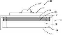
- Fig. 1is a front view showing the structure of a first embodiment of a kinetic energy generating device and a wireless transmitter according to the present invention.
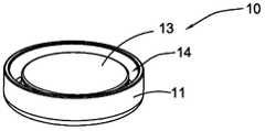
- FIG. 2is a perspective view showing the structure of the magnetic circuit system in the first embodiment of the kinetic energy generating device according to the present invention.
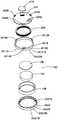
- FIG. 3is a schematic exploded view of the magnetic circuit system illustrated in FIG. 2.
- 4 to 6are schematic views showing the movement process of the kinetic energy generating device according to the present invention.
- Fig. 7is a schematic view showing the exploded structure of a second embodiment of the kinetic energy generating device and the wireless transmitter according to the present invention.
- FIGS. 8 to 10are schematic diagrams showing the working principle of the second first embodiment of the kinetic energy generating device and the wireless transmitter according to the present invention.
- Figure 11is a front elevational view showing the third embodiment of the kinetic energy generating device and the wireless transmitter of the present invention.
- Figure 12is a perspective view showing the third embodiment of the kinetic energy generating device and the wireless transmitter according to the present invention.
- Figure 13is a schematic view showing the exploded structure of a third embodiment of the kinetic energy generating device and the wireless transmitter according to the present invention.
- FIG. 14 to FIG. 16are schematic diagrams showing the working principle of a third embodiment of the kinetic energy generating device and the wireless transmitter according to the present invention.
- Figure 17is a perspective view showing the structure of a fourth embodiment of the kinetic energy generating device and the wireless transmitter of the present invention.
- Figure 18is a schematic view showing the exploded structure of a fourth embodiment of the kinetic energy generating device and the wireless transmitter according to the present invention.
- Figure 19is a schematic illustration of the direction of motion of the drive unit in the wireless transmitter of Figure 17.
- 20 to 21are schematic diagrams showing the working principle of the fourth embodiment of the kinetic energy generating device and the wireless transmitter according to the present invention.
- the present inventionmainly provides a kinetic energy generating device, wherein the kinetic energy generating device provides a magnetic gap and a coil, and an exciting current is generated by the coil reciprocating in the magnetic gap, thereby causing the kinetic energy of the present invention.
- the power generation deviceachieves the effect of generating electricity.
- the kinetic energy generating deviceincludes a magnetic circuit system 10, a driving device 20, and a coil 30.
- the gap 14is formed in the magnetic circuit system 10, and the coil 30 is fixedly disposed on the driving device 20, and can reciprocate in the magnetic gap 14 under the driving of the driving device 20 to generate an induced current. Therefore, the kinetic energy generating device of the present invention achieves the effect of generating electricity.
- the magnetic circuit system 10forms an annular magnetic gap 14, and the coil 30 and the magnetic gap 14 are capable of generating a relative displacement, thereby causing the coil to generate an induced current, thereby performing a power generating operation.
- the magnetic gap 14may be fixed in position, and the coil 30 may move, or the coil 30 may be fixed in position, and the position of the magnetic gap 14 may be changed, thereby causing the coil 30 and A relative displacement occurs between the magnetic gaps 14.
- the magnetic circuit system 10may be stationary, and the driving device 20 is used to drive the coil 30 to move, or the coil 30 is fixed, and the driving device 20 is used for driving the driving station.
- the magnetic circuit system 10is moved such that the coil 30 and the magnetic circuit system 10 are relatively displaced, and the coil 30 reciprocates rapidly in the magnetic gap 14, causing the coil 30 to be magnetized.
- the magnetic line of the road system 10is fast
- the cuttingis performed to generate an induced current in the coil 30 based on the principle of electromagnetic induction.
- the drive unit 20is used to drive the coil 30 to generate an induced current.
- the magnetic circuit system 10includes a top magnetic conductive plate 13, a permanent magnet 12, and a bottom magnetic conductive plate 11.
- the bottom magnetic conductive plate 11has a recess 111
- the permanent magnet 12is disposed in the recess 111 of the bottom magnetic conductive plate 11 and has a space between the side walls of the bottom magnetic conductive plate 11 a top magnetic field 13 is attached to the top surface of the permanent magnet 12, so that the top magnetic conductive plate 13 and the permanent magnet 12 form a magnetic line in the bottom magnetic conductive plate 11
- the magnetic gap 14 of the ringis
- the bottom magnetic conductive plate 11is a cylindrical magnetic conductive plate whose longitudinal section is U-shaped, so that the groove 111 is also cylindrical, and the The magnet 12 is cylindrical and located in the groove 111 of the cylindrical bottom magnetic conductive plate 11 and the outer diameter of the permanent magnet 12 is smaller than the diameter of the groove 111, and the top magnetic conductive plate 13 is also The cylindrical shape and the outer diameter thereof are the same as the outer diameter of the permanent magnet 12, and therefore, the magnetic gap 14 in which the magnetic line is densely formed can be formed between the top magnetic conductive plate 13 and the bottom magnetic conductive plate 11.
- the top magnetic conductive plate 13 and the bottom magnetic conductive plate 11may also adopt other shapes or structures, for example, the bottom magnetic conductive plate 11 has a longitudinal cutting surface.
- a U-shaped hollow rectangular parallelepiped or the likemay be formed as long as the top magnetic conductive plate 13 and the permanent magnet 12 can form the magnetic flux line 14 in the bottom magnetic conductive plate 11.
- those skilled in the artcan also determine the manner of forming the magnetic gap 14 according to actual conditions, as long as the magnetic gap 14 can be generated, which belongs to the protection range of the kinetic energy generating device according to the present invention, and the present invention
- the specific implementation manneris not limited thereto.
- the driving device 20includes a driver, which in this embodiment is implemented as a magnetizer 21, which It is made of a magnetically permeable magnetic material. It can be understood that The driver may also be formed by coating a surface of a non-magnetically permeable material with a magnetically permeable material, and the invention is not limited in this respect.
- the driveris embodied as an iron plate.
- the coil 30has an O-shaped cross section and is fixed to a bottom surface of the magnetizer 21, and when the magnetizer 21 is placed on a top surface of the top magnetic conductive plate 13, the coil 30 can be inserted into the Magnetic gap 14.
- the magnetizer 21Due to the magnetic permeability of the magnetizer 21, when the magnetizer 21 is placed on the surface of the top magnetic conductive plate 13, it is tightly adsorbed due to the suction force of the permanent magnet 12 under the top magnetic conductive plate 13. On the top surface of the top magnetically permeable plate 13, and the coil 30 is correspondingly located in the magnetic gap 14, and the coil 30 is still in the magnetic gap 14 while still located in the magnetic circuit system 10. When the magnetic adsorption field is within the range, the coil 30 can be quickly moved back to the top magnetic conducting plate 13 under the magnetic attraction of the magnetic circuit system 10.
- FIG. 4 to FIG. 6are schematic diagrams showing the working process of the first embodiment of the kinetic energy generating device according to the present invention.
- the coil 30is located in the magnetic gap 14.
- the kinetic energy generating deviceis in a stationary state.
- the magnetizer 21is rapidly moved downward and reset under the magnetic attraction force of the permanent magnet 12 until it is reattached to the surface of the top magnetic conductive plate 13. Attached.
- the coil 30 fixedly disposed with the magnetizer 21is also rapidly moved downward by the magnetizer 21 to be inserted into the magnetic gap 14.
- the rapid movement of the coil 30 in the magnetic gap 14causes the coil 30 to be rapidly cut by the magnetic line of interest in the magnetic gap, thereby generating the induced current in the coil 30.
- the induced currentcan be used to drive a corresponding device to operate.
- the magnetizer 21is an iron plate.
- those skilled in the artmay make changes to the type of the magnetizer 21 according to actual conditions, such as cobalt, nickel, and alloys thereof.
- a person skilled in the artmay modify a specific technical solution according to the disclosure of the present invention, such as setting the coil 30 to move, and moving the magnetic circuit system 10, and then passing the magnetic circuit system.
- the magnetic induction line in 10cuts the coil to generate a current, in other words, as long as the coil 30 is cut by the magnetic line in the magnetic circuit system 10, a current can be generated, so that the present invention is employed.
- the same or similar technical solutions and the same or similar technical effects as the present inventionare all within the scope of the present invention, and the specific embodiments of the present invention are not limited thereto.
- the width of the magnetic gap 14is between 0.5 mm and 10 mm, and the number of turns of the coil 30 is between 50 and 800, the coil The wire diameter of 30 may be between 0.06 mm and 0.5 mm, and those skilled in the art may determine the width of the magnetic gap 14 and the number of turns of the coil 30 and the wire diameter of the coil 30 according to the demand for the electric power size, as long as
- the technical solutions that are the same as or similar to the present inventionare adopted, and the technical effects that are the same as or similar to the present invention are all within the scope of the present invention, and the specific embodiments of the present invention are not limited thereto.
- the return movement of the coil 30 in the magnetic gap 14may be achieved by suction, or may be elastic.
- the reciprocating motion of the coil 30 in the magnetic gap 14is realized, or the reciprocating motion of the coil 30 in the magnetic gap 14 is realized by inertial force, external force, or the like, and can be determined by a person skilled in the art according to specific conditions.
- the specific embodiment of the kinetic energy generating device of the present inventionis not limited thereto.
- the coil 30is electrically connected to the circuit board 22, and the circuit board 22 can be integrated with a series of circuit components 221, and the circuit board 22 can be fixed to the magnetizer 21 implemented as an iron plate.
- the top sidei.e., on the top side of the magnetic circuit system 10, forms a compact structure, as shown in Figure 4, although it will be understood by those skilled in the art that it may also be the circumference of the magnetic circuit system 10.
- the sidemay be electrically connected to the coil 30.
- the induced current generated by the coil 30will be converted to use power by a voltage converter in the circuit board 22 to provide power to the main control module of the board.
- the main control modulecan also generate a control command, and the control command is sent to various electronic devices through the high frequency radio frequency circuit, thereby Manipulating the electronic device.
- the control commandis sent to an electronic control system, and the electronic control system can function as a smart home control system, it can be operatively connected to different electronic devices through a central control unit, such as a illuminator, a curtain control unit air conditioner. Control unit, intelligent indicator unit, etc.
- the kinetic energy generating device of the present inventioncan be applied to a self-generating wireless switch, wherein the self-generating wireless switch is adapted to connect any electronic device.
- the self-generating wireless switch in which the kinetic energy generating device of the present invention is disposedis a self-generating device that controls the electronic device in a switching manner.
- the self-generating wireless switch according to the preferred embodimentis used to control one illuminator in a switching manner. It should be appreciated that the self-generating wireless switch can activate and deactivate other electronic devices, such as home or office appliances such as televisions, refrigerators, and electric fans.
- a kinetic energy generation methodfor providing power to a small electronic device, such as typically applied to a wireless switch, thereby forming a wireless self-generating switch, the method comprising the steps of: The magnet 21 is moved by an external force to drive the coil 30 connected thereto away from the annular magnetic gap 14 of the magnetic circuit system 10 by a predetermined distance;
- the magnetizer 21is magnetic in the magnetic circuit system 10 when the external force action disappears Re-absorption with the magnetic circuit system 10 under the action of the absorption force, while the coil 30 returns to the magnetic gap 14, causing the coil 30 to be cut by the magnetic line of the magnetic circuit system 10 and generating an induced current. Used for power generation.
- the iron platewhen the external force is used to lift the magnetizer 21, which is implemented as an iron plate, as shown in the figure, when the coil 30 is separated from the magnetic gap 14 by a predetermined interval, the iron plate is subjected to a downward pulling force of the magnet. Therefore, the coil 30 has potential energy. Since the iron plate is normally adsorbed by the magnet, when the external force attempts to separate it from the magnet, it will be subjected to the strong attraction of the magnet to maintain the potential energy. When the external force suddenly disappears, the iron plate will move down quickly under the attraction of the magnet until it re-engages with the magnet.
- the coil associated with the iron plateis also rapidly inserted downward into the magnetic gap 14, and the rapid movement of the coil causes the coil 30 to be quickly cut by the magnetic induction line.
- the coil 30will be An induced current is generated in it.
- the magnetizer 21when applied to a wireless switch or other small electronic device, it may be an external force of a user pressing, pushing, pushing, pulling, etc., causing the magnetizer 21 as the driver to move and leave the device.
- the magnetizer 21When the magnetic gap 14 is described and the external force applied by the user suddenly disappears, the magnetizer 21 will automatically return to the initial phase suction position under the magnetic attraction of the magnetic circuit system 10, so that the coil 30 is re-established. Entering the magnetic gap 14, such rapid reciprocation as to exit and enter the magnetic gap 14 causes it to be rapidly cut by the magnetic line of the magnetic circuit system 10 to cause an induced current.
- the magnetizer 21is automatically reset due to the magnetic action of the magnetic circuit system 10, so that the structure is simpler.
- the magnetizer 21may be further automatically reset by other means, such as by elastic deformation recovery performance to drive the magnetizer 21 to reset, ie, for example, the magnetizer 21 is coupled to a spring.
- the magnetizer 21is coupled to a spring.
- the coil 30in the initial state, the coil 30 is located in the magnetic gap 14, and in a primary power generating operation, the coil 30 is located in the magnetic gap 14 to leave the magnetic gap 14, The magnetic gap 14 is then returned. In other embodiments, it is also possible that in the initial state, the coil 30 is located outside the magnetic gap 14 in a power generation operation. The coil 30 is located outside the magnetic gap 14 to enter the magnetic gap 14 and then exit the magnetic gap 14. In summary, the coil 30 is caused to quickly enter and exit the magnetic gap 14, thereby causing induced currents in the coil 30.
- the wireless transmitterincludes a magnetic circuit system 10A.
- a driving device 20A and a coil 30Athe magnetic circuit system 10A includes a top magnetic conductive plate 13A, a permanent magnet 12A and a bottom magnetic conductive plate 11A.
- the permanent magnet 12Ais disposed on the bottom magnetic conductive plate 11A.
- the wireless transmitteruses a spring 21A to drive the coil 30A to reciprocate in the magnetic gap 14A to generate the induced current, and drives the circuit board 22A through the induced current. Launched.
- FIG. 7is a schematic view of an exploded structure of a first embodiment of the present invention.
- the circuit board 22Ais electrically connected to the coil 30 of the kinetic energy generating device, wherein the driving device 20A in the kinetic energy generating device includes a driver, which is Specifically, the elastic piece 21A is fixedly disposed on the bottom surface of the elastic piece 21A. The top surface of the elastic piece 21A is fixedly disposed with the circuit board 22A, and the circuit board 22A and the coil 30A are electrically connected.
- the coil 30Ais reciprocated in the magnetic gap 14A by the elastic force of the elastic piece 21A, thereby realizing the power generation effect of the kinetic energy power generation device.
- the circuit board 22Aneed not be fixed on the top surface of the elastic piece 21A, but is fixed at other positions of the entire power generation system.
- the elastic piece 21Ahas a first end 211A and a second end 212A.
- the first end 211Ahas a first fixing hole 2111A and a second fixing hole 2112A.
- the kinetic energy generating device of the embodiment of the present inventionfurther includes a base 40.
- the base 40is fixedly provided with a first fixing base 41 and a second fixing base 42, the first fixing base 41 and the The height of the second fixing base 42 is the same, and the elastic piece 21A passes through the first fixing hole 2111A and the second fixing hole 2112A respectively.
- the first fixing base 41 and the second fixing base 42are fixed to fix the base 40.
- the elastic piece 21Acan not only achieve relative fixation with the base 40, but also can be operated without external force.
- the horizontal positionis maintained, and the second end 212A of the elastic piece 21A is movable relative to the first end 211A of the elastic piece 21A when an external force is applied.
- the proximal end of the elastic piece 21Ais fixed in position by one or more fixing seats 41 and 42, and the bottom surface of the distal end fixes the coil 30A.
- the distal end of the elastic piecethat is, the second end 212A, can be rotated with its proximal end, that is, the first end 211A as a fulcrum, so as to be automatically reset. That is, unlike the above embodiment, the coil 30 is reset by magnetic attraction, and in this embodiment of the invention, the coil 30A is automatically reset by the elastic recovery property of the elastic piece 21A.
- the magnetic circuit system 10Ais located below the second end 212A of the elastic piece 21A, and the heights of the first fixing seat 41 and the second fixing seat 42 can ensure that the elastic piece 21A is just right when it is stationary.
- the coil 30Ais located in the magnetic gap 14A formed by the magnetic circuit system 10A. In other words, when the elastic piece 21A is stationary without an external force, its height is approximately the same as the height of the magnetic circuit system 10A, thereby ensuring that the coil 30A can be released when the external force on the elastic piece 21A disappears.
- the kinetic energy generating device of the present inventionLocated in the magnetic gap 14A formed by the magnetic circuit system 10A, the kinetic energy generating device of the present invention has a power generating function.
- the shape of the second end 212A of the elastic piece 21Acan ensure that the O-shaped coil 30A is fixed to the bottom surface thereof.
- the second end 212A of the elastic piece 21Ais a circular shape, and the circular second end 212A is an enlarged portion whose outer diameter is larger than the outer diameter of the coil 30A, so that the coil 30A can be stably fixed to the bottom surface of the second end 212A of the elastic piece 21A.
- the second end 212A of the elastic piece 21Afurther has a protrusion 2121A located at a side of the second end 212A of the elastic piece 21A for convenient operation by a user.
- FIG. 8 to FIG. 10are schematic diagrams showing a power generation process of the wireless transmitter according to this embodiment of the present invention.
- the second end 212A of the elastic piece 21A and the coil 30Aare located above the magnetic circuit system 10A, and at the same time, the coil 30A is located in the magnetic gap 14A formed by the magnetic circuit system 10A. At this time, the entire kinetic energy generating device is at a standstill.
- the circuit board 22Ais a high frequency wireless transmission circuit board, and the high frequency wireless transmission circuit board is integrated with a series of circuit board components 221A and a radio frequency module (RF radio frequency module).
- RF radio frequency moduleradio frequency module
- the coil 30A in the kinetic energy generating deviceis electrically connected to the high frequency wireless transmitting circuit board.
- the coil 30A in the kinetic energy generating deviceis densely covered by the magnetic gap 14A
- the induced currentdrives the high frequency wireless transmitting circuit board with the circuit board component 221A and the RF radio frequency module to emit high frequency radio waves, thereby controlling the electronic device working.
- the elastic piece 21A as a driver in this embodiment of the inventionpulsates the coil 30A in a lever-like manner to generate a rapid reciprocating displacement, thereby causing the coil 30 to generate an induced current.
- the coil 30Ain the initial state, the coil 30A is located in the magnetic gap 14A, and when the protrusion 2121A is lifted upward, so that the second end 212A of the elastic piece 21A is When the first end 211A is rotated upward by the fulcrum, the coil 30A leaves the magnetic gap 14A and the elastic piece 21A accumulates potential energy. When the external force disappears, the elastic piece 21A is automatically reset, thereby driving the coil 30A to enter again.
- the magnetic gap 14Ais described so as to be rapidly cut by the magnetic line of the magnetic circuit system 10A to generate an induced current. It can be understood that, in another embodiment, the height of the fixing bases 41 and 42 may be greater than the magnetic circuit system 10A, so that in the initial state, the coil 30A is located in the magnetic gap 14A.
- the coil 30Aenters the magnetic gap 14A and The elastic piece 21A accumulates potential energy, and when the external force disappears, the elastic piece 21A is automatically rotated upward and reset, thereby driving the coil 30A away from the magnetic gap 14A, so that the coil 30A quickly enters and leaves the magnetic gap 14A, The coil 30A is caused to be rapidly cut by the magnetic line of the magnetic circuit system 10A to generate an induced current.
- this embodiment of the inventionprovides a kinetic energy generation method for providing power to a small electronic device, such as typically applied to a wireless switch, thereby forming a wireless self-generating switch, the method comprising the following step:
- the elastic piece 21Ais leveraged by the second end 212A with the first end 211A as a fulcrum and elastically deformed by the external force, and drives the coil 30 connected thereto to leave the annular magnetic gap 14A of the magnetic circuit system 10A by a predetermined distance;
- the elastic piece 21Aautomatically resets and drives the coil 30A to automatically reset, wherein the coil 30A is cut by the magnetic induction line of the magnetic circuit system 10A to generate an induced current for power generation.
- the elastic piece 21Ais leveraged by the second end 212A with the first end 211A as a fulcrum and elastically deformed by the external force, and drives the coil 30A connected thereto to enter the annular magnetic gap 14A of the magnetic circuit system 10A;
- the elastic piece 21Aautomatically resets and drives the coil 30A away from the magnetic gap 14A, wherein the coil 30A is cut by the magnetic line of the magnetic circuit system 10A to generate an induced current for use in Power generation.
- the external force applied by the elastic piece 21Amay be a direct action from the user, or may be other indirect effects, as long as it can cause displacement of the distal end of the elastic piece 21A, thereby accumulating elasticity. Potential energy can be.
- the distal end of the elastic piece 21Acan be fixed to the magnetic circuit system 10A. Therefore, when the elastic piece 21A is subjected to an external force and its distal end is rotated relative to its proximal end, like a lever, the position of the coil 30A is unchanged and the magnetic circuit system 10A can be driven to move, and the external force suddenly disappears.
- the elastic piece 21Ais automatically reset due to the elastic recovery performance, the magnetic circuit system 10A is automatically reset, so that the magnetic gap 14A of the magnetic circuit system 10A and the coil 30A are relatively reciprocated. The displacement causes the coil 30A to generate an induced current.
- the coil 30Amay be located in the magnetic gap 14A, or may be located outside the magnetic gap 14A in a repeated cycle. In the middle, the movement of the magnetic circuit system 10A may cause the magnetic gap 14A to leave the coil 30A to return quickly, or the movement of the magnetic circuit system 10A may cause the magnetic gap 14A to be first placed in the The coil 30A is quickly separated from the coil 30A.
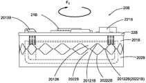
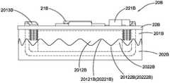
- the wireless transmitterincludes a magnetic circuit system 10B, a driving device 20B, and a coil 30B.
- the magnetic circuit system 10Bincludes a top magnetic conductive plate 13B, a permanent magnet 12B, and a bottom magnetic conductive plate 11B.
- the permanent magnet 12Bis disposed in the groove of the bottom magnetic conductive plate 11B and is magnetically coupled to the bottom.
- a magnetically sensitive wireis formed in the magnetic conductive plate 11B
- the magnetic gap 14Bis shaped.
- the third embodiment of the wireless transmitterdiffers from the first embodiment in that, in the third embodiment, the coil 30B is driven by the relative circumferential rotational motion of a cam in the magnetic gap 14B. The upper and lower reciprocating motions are performed to generate the induced current, and the circuit board 22B is driven by the induced current to perform a corresponding transmitting operation.
- the driving device 20Bincludes a driver including a cam having a cylindrical shape including an upper cam 201B and a lower portion.
- the cam 202Bhas a first space 2011B and the lower cam 202B has a second space 2021B.
- a plurality of consecutive first protruding teeth 2012Bare disposed on a circumference of the upper cam 201B, and each of the first protruding teeth 2012B includes a first upper end 20121B and a first lower end 20122B.
- the lower cam 202Bis provided with a plurality of second protruding teeth 2022B respectively engaged with the first protruding teeth 2012B, and each of the second protruding teeth 2022B includes a second upper end 20221B and a The second lower end 20222B.
- the first upper end 20121B of the first protruding tooth 2012Bis located at the second upper end 20221B of the second protruding tooth 2022B, and The first lower end 20122B of the first protruding tooth 2012B is located at the second lower end 20222B of the second protruding tooth 2022B;
- the upper cam 201Bperforms a circumferential rotational movement with respect to the lower cam 202B, the upper cam 201B
- the first upper end 20121B and the first lower end 20122B of the first protruding tooth 2012Bare respectively along the second upper end 20221B and the second lower end of the second protruding tooth 2022B on the lower cam 202B
- the 20222Bslides to reciprocate the upper cam 201B relative to the lower cam 202B.
- the wireless transmitterfurther includes a circuit board 22B, and the circuit board 22B is fixedly disposed on the upper cam 201B.
- the upper cam 201Bis provided with at least one buckle 2013B on the periphery thereof, and the peripheral edge of the circuit board 22B is provided with the same number of the card holes 222B as the buckles, so as to pass the buckle 2013B.
- the circuit board 22Bis fixed to the upper cam 201B in combination with the card hole 222B.
- three of the buckles 2013Bare disposed on the periphery of the upper cam 201B, and three corresponding card holes 222B are also disposed at corresponding positions of the circuit board 22B.
- the buckle 2013Bcan also be disposed on the circuit board 22B, and the card hole 222B can also be disposed on the upper cam 201B.
- the circuit board 22B and the upper cam 201Bmay be connected and fixed by other connection means, and the present invention is not limited in this respect.
- the coil 30Bis fixed to the bottom surface of the circuit board 22B and located in the first space 2011B of the upper cam 201B, and the top surface of the circuit board 22B further includes a magnetizer 21B, the guide The magnet 21B is fixed to the top surface of the circuit board 22B, and may be formed of a magnetically permeable material such as an iron plate or a magnetically permeable material coated with a non-magnetic material.
- the magnetic circuit system 10Bhas the same structure as that in the magnetic circuit system 10 of the first embodiment of the kinetic energy generating device, the magnetic circuit The system 10B is located in the second space 2021B of the lower cam, and when the upper cam 201B and the lower cam 202B are engaged, the coil 30B is located in the magnetic gap 14B formed by the magnetic circuit system 10B. in.
- the magnetizer 21Bmay also be located on the bottom surface of the circuit board 22B or integrated integrally with the circuit board 22B as long as it can generate magnetic attraction with the magnetic circuit system 10 and The cam is automatically reset to the engaged state.
- the magnetizer 21Bis fixed to the upper cam 201, and the circuit board 22B is fixedly coupled to the magnetizer 21B.
- FIG. 14 to FIG. 16are schematic diagrams showing the working process of the third embodiment of the wireless transmitter of the present invention.
- the magnetizer 21Bis affected by the magnetic force of the magnetic circuit system 10B, and when the upper cam 201B is continuously rotated rapidly, the first portion on the upper cam 201B is caused.
- a convex tooth 2012B and the second convex tooth 2022B on the lower cam 202Bare re-engaged, and at this time, the coil 30B falls back into the magnetic gap 14B as the upper cam 201B moves downward downward. And is quickly cut by the magnetic line of interest in the magnetic gap 14B.
- the rotation directions of the upper cam 201B and the lower cam 202Bmay be adjusted according to actual conditions, as long as the upper cam can be enabled.
- the 201B and the lower cam 202Bperform a circular motion along the first convex teeth 2012B and the second convex teeth 2022B, thereby driving the coil 30B to reciprocate in the magnetic gap 14B to generate an induced current.
- the magnetizer 21Bis embodied as an iron plate, and a person skilled in the art can also determine the specific material of the magnetizer 21B according to actual conditions.
- itmay be a magnetic material opposite to the magnetic pole of the magnetic circuit system 10B, and the specific embodiment of the present invention is not limited thereto as long as the magnetic permeability is within the scope of the present invention.
- a person skilled in the artcan also adjust the motion relationship between the upper cam 201B and the lower cam 202B according to customer needs or actual conditions.
- those skilled in the artcan set the upper cam 201B to be fixed, and the lower cam 202B carries the second protruding teeth 2022B along the first protruding teeth 2012B with respect to the upper cam 201B.
- Circular motionThat is, those skilled in the art can set the coil 30B to be stationary, and the magnetic circuit system 10B reciprocates relative to the coil 30B to generate the induced current.
- the specific implementation of the wireless transmitter of the present inventionis not To this end, as long as the same or similar technical solutions as the present invention are adopted, and the same or similar technical effects as the present invention are achieved, they are all within the protection scope of the wireless transmitter of the present invention.
- the circuit board 22Bis a high frequency wireless transmitting circuit board, and the high frequency wireless transmitting circuit board is electrically connected to a circuit board component 221B and a
- the RF moduleRF radio frequency module
- the coil 30B in the kinetic energy generating deviceis electrically connected to the high frequency wireless transmitting circuit board.
- the coil 30B in the kinetic energy generating devicegenerates an induced current due to a magnetic line cut in the magnetic gap 14B
- the induced currentdrives the board member 221B and the The high frequency wireless transmitting circuit board of the RF module emits high frequency radio waves to control the operation of the electronic device.
- this embodiment of the inventionprovides a kinetic energy generation method for providing power to a small electronic device, such as typically applied to a wireless switch, thereby forming a wireless self-generating switch, the method comprising the following step:
- the upper cam 201Bstarts to separate from the lower cam 202B by an external force, and drives the circuit board 22B connected thereto to move, so that the coil 30 assembled to the circuit board 22B leaves the ring of the magnetic circuit system 10B.
- the magnetic gap 14Bis a predetermined distance;
- the magnetic attraction between the magnetizer 21B and the magnetic circuit system 10Bautomatically resets the upper cam 201B and the circuit board 22B and drives the coil 30B to automatically reset.
- the coil 30Bis cut by the magnetic line of the magnetic circuit system 10B to generate an induced current for power generation.
- the lower cam 202Bstarts to separate from the upper cam 201B by an external force, and drives the magnetic circuit system 10B connected thereto to move, so that the coil 30B assembled to the circuit board 22B is separated. Opening the annular magnetic gap 14B of the magnetic circuit system 10B by a predetermined distance;
- the lower cam 202Bis automatically reset to mesh with the upper cam 201B, and the magnetic circuit system 10B is driven to automatically reset, so that the coil 30 enters the magnetic circuit system 10B.
- the magnetic gap 14Bis described in which the coil 30A is cut by the magnetic line of the magnetic circuit system 10B to generate an induced current for power generation.
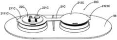
- the wireless transmitteris The coil 30C is reciprocated in the magnetic gap 14C formed by the magnetic circuit system 10C by using the up and down movement of a slab, thereby generating an induced current, and driving the circuit board 22C by the induced current.
- the corresponding launch workis that, in this embodiment, the wireless transmitter is The coil 30C is reciprocated in the magnetic gap 14C formed by the magnetic circuit system 10C by using the up and down movement of a slab, thereby generating an induced current, and driving the circuit board 22C by the induced current.
- the wireless transmitterincludes a bottom plate 50, a kinetic energy generating device, and a circuit board 22C.
- the kinetic energy generating deviceis fixed on the floor and can generate an induced current.
- the circuit board 22Cis electrically connected to the kinetic energy generating device and is capable of performing a corresponding transmitting operation under the driving of the induced current.
- the driving deviceincludes a driver, which in this embodiment is embodied as a seesaw, the seesaw includes a The first end 21C and the second end 21C' are fixedly disposed with a point 503 on the bottom plate 50.
- the two sides of the fulcrum 503are respectively provided with two mounting seats to respectively form a first recess 501 and a first
- the two grooves 502are understood to be recessed to the bottom plate 50, and the invention is not limited in this respect.
- the kinetic energy generating device of the wireless transmitterincludes a first kinetic energy generating unit and a second kinetic energy generating unit, and the first kinetic energy generating unit and the second kinetic energy generating unit are respectively fixed
- the first groove 501 and the second groove 502are disposed on both sides of the fulcrum 503.
- the first kinetic energy generating unitincludes a first magnetic circuit system 10C, a first coil 30C and a first driving device 20C.
- the first magnetic circuit system 10Chas a first magnetic gap 14C
- the power generating unitincludes a second magnetic circuit system 10C', a second coil 30C', and a second driving device 20C'.
- the second magnetic circuit system 10C'has a second magnetic gap 14C', wherein the first The driving device 20C can drive the first coil 30C to reciprocate in the first magnetic gap 14C formed by the first magnetic circuit system 10C.
- the second driving device 20C'can drive the second coil 30C' to reciprocate in the second magnetic gap 14C' formed by the second magnetic circuit system 10C'.
- the circuit board 22Cis electrically connected to the first coil 30C and the second coil 30C', and performs a corresponding control command transmitting operation by driving the first induced current and the second induced current.
- the two driving devices 20Cform an integral driver structure, more specifically a slab that moves with the fulcrum portion 503 as a fulcrum.
- the two kinetic energy generating unitsmay be symmetrically located on both sides of the fulcrum portion 503, or may be reasonably allocated according to actual conditions to achieve a phase equilibrium state. For example, when the circuit board 22C is fixed to the left side of the seesaw, the fulcrum portion 503 may be located adjacent to the first kinetic energy generating unit on the left side.
- the number of coils and the wire diameter of the two coils 30C and 30C'may be the same or different.
- the first magnetic circuit system 10Cincludes a cylindrical first bottom magnetic conductive plate 11C having a U-shaped longitudinal section, a first permanent magnet 12C and a first top magnetic conductive plate 13C.
- the first bottom magnetic conductive plate 11Cis fixedly disposed in the first recess 501, and the first permanent magnet 12C and the first top magnetic conductive plate 13C are both cylindrical and the first permanent magnet 12C
- the first top magnetic conductive 13C plateis attached to the top surface of the first permanent magnet 12C so that the first magnetic circuit system 10C can be formed.
- the magnetic fluxis densely covered by the first magnetic gap 14C.
- the second magnetic circuit system 10C'includes a cylindrical second bottom magnetic conductive plate 11C' having a U-shaped longitudinal section, a second permanent magnet 12C' and a second top magnetic conductive plate 13C'.
- the second bottom magnetic conductive plate 11C'is fixedly disposed in the second recess 502, and the second permanent magnet 12C' and the second top magnetic conductive plate 13C' are both cylindrical and the first
- the second permanent magnet 12C'is disposed inside the second bottom magnetic conductive plate 11C', and the second top magnetic conductive plate 13C' is attached to the top surface of the second permanent magnet 12C' to make the first
- the second magnetic gap 14C' in which the magnetic line is densely formedcan be formed in the two magnetic circuit system 10C'. It is to be understood that the above-described magnetic gaps 14C and 14C' are annular, and the shape of the above-mentioned magnetic conductive plate is not limited to the above cylindrical shape.
- the first coil 30Cis O-shaped and fixedly disposed on a bottom surface of the first driving device 20C, and the first driving device 20C can drive the first coil 30C to enter the first magnetic circuit system 10C. In the first magnetic gap 14C.
- the second coil 30C'is O-shaped and fixedly disposed on a bottom surface of the second driving device 20C', and the second driving device 20C' can drive the second coil 30C' into the second magnetic circuit system 10C. 'In the second magnetic gap 14C' formed.
- the first driving device 20Cdrives the first coil 30C through the first end 21C of the seesaw.
- the second driving device 20C'is driving the second coil through the second end 21C' of the raft 30C' reciprocates in the second magnetic gap 14C' formed by the second magnetic circuit system 10C'.
- the circuit board 22Cis fixedly disposed on the top surface of the first driving device 20C. It is to be understood that the circuit board 22C may also be located on the top surface of the second driving device 20C', or in the middle of the seesaw, or may be fixed to the bottom plate 50.
- the first driving device 20C and the second driving device 20C'are connected to each other to form the seesaw, the fulcrum portion 503 is located in the middle of the bottom surface of the seesaw, and the two ends of the seesaw are symmetrically arranged
- the right side of 20C'is such that the other end of the raft can be tilted with the same force. It can be understood that the above-mentioned protrusions 211C and 211C' are arranged for convenient operation, and the user may directly press or lift both ends of the seesaw, and the aspect of the invention is not limited.
- the first driving device 20Cwhen an external force is applied to press the first protrusion 211C in the seesaw, the first driving device 20C is moved downward by the external force F3, and the second The driving device 20C' is tilted under the reaction of the fulcrum portion 503 and the external force F3.
- the first driving device 20C and the second driving device 20C'can swing up and down in the direction of the arrow shown by the external force F3 centering on the fulcrum portion 503.
- the outputs of the two coils 30C and 30C'are both connected to the circuit board 22C, and the two coils 30C and 30C' may be connected in series or in parallel.
- the fourth implementation of the wireless transmitter of the present inventionThe working process schematic of the example.
- the arrow in the figureindicates that the coil 30C on the left side moves downward, the coil 30C' on the right side moves upward; and when the coil 30C' on the right side moves downward, the coil 30C on the left side is upward. motion.
- the side of the seesawis lower on one side, that is, either one of the first driving device 20C or the second driving device 20C' and the first magnetic circuit system 10C or the second magnetic circuit system 10C' contacts, and drives the first coil 30C into the first magnetic gap 14C formed by the first magnetic circuit system 10C or drives the second coil 30C' into the The second magnetic gap 14C' formed by the second magnetic circuit system 10C'.
- the initial positionis that the first driving device 20C drives the first coil 30C into the first magnetic gap 14C formed by the first magnetic circuit system 10C.
- the second driving device 20C' in the second kinetic energy generating unitis rapidly moved downward by the external force F3'.
- the second driving device 20C'drives the second coil 30C' to move downward rapidly, thereby quickly entering the second magnetic gap 14C' formed by the second magnetic circuit system 10C', and being The closed magnetic line of interest in the second magnetic gap 14C' is rapidly cut to generate a second induced current.
- the first driving device 20Cperforms a motion opposite to the direction of the second driving device 20C' under the action of the external force F3' and the fulcrum portion 503, that is, When the first driving device 20C moves upward, the first coil 30C leaves the first magnetic gap 14C formed by the first magnetic circuit 10C under the driving of the first driving device 20C, so that the first When the coil 30C leaves the first magnetic gap 14C in the first magnetic circuit system 10C, it is bound to be cut by the magnetic line of interest in the first magnetic gap 14C, thus generating a first induced current.
- the first coil 30Cleaves the magnetic gap 14C, that is, in the left-handed state in the figure, a downward external force F3 is applied to the first protrusion 211C, then the first The driving device 20C rapidly moves downward under the driving of the external force F3, while driving the first coil 30C to quickly enter the first magnetic gap 14C in the first magnetic circuit system 10C, thereby causing the The first coil 30C is quickly cut by the magnetic flux line densely covered in the first magnetic gap 14C, thereby generating the first induced current again.
- the second driving device 20C'moves rapidly upwards under the joint action of the external force F3 and the fulcrum portion 503, and simultaneously drives the second coil 30C' to quickly leave the second magnetic circuit system 10C'.
- the second magnetic gap 14C' in the middleis rapidly cut by the dense magnetic line in the second magnetic gap 14C', so that the second induced current is generated again.
- the wireless transmitter of the present inventioncan generate primary electric energy, and the first driving device 20C and the second driving device 20C' continuously move in such a reciprocating manner, thereby continuously generating the first An induced current and the second induced current. Since the circuit board 22C is electrically connected to the first coil 30C and the second coil 30C', the first induced current and the second induced current can drive the circuit board 22C to perform corresponding wireless transmission. jobs. Accordingly, those skilled in the art can design the circuit module of the circuit board 22C to supply the induced current generated by the first and second coils 30C and 30C' in series or in parallel.
- the circuit board 22Cis disposed on a top surface of the first driving device 20C, and the first coil 30C and the second coil 30C' Both are electrically connected to the circuit board 22C to provide current drive for the circuit board 22C.
- a person skilled in the artmay also connect the first coil 30C and the second coil 30C' to different circuit boards 22C according to actual conditions, thereby inducing the induced current generated by the first kinetic energy generating device and the second The induced current shunt output generated by the kinetic energy generating device drives different boards for corresponding wireless transmitting work.
- the circuit board 22Cis a high frequency wireless transmitting circuit board, and the high frequency wireless transmitting circuit board is electrically connected to a circuit board component 221C and a a radio frequency module (RF radio frequency module) (not shown in the drawings, the same below), that is, the first coil 30C and the second coil 30C' in the kinetic energy generating device and the high frequency wireless transmitting circuit board, respectively Electrical connection.
- RF radio frequency moduleradio frequency module
- the induced currentis generated when the first coil 30C and the second coil 30C' are induced by a magnetic line cut in the first magnetic gap 14C and the second magnetic gap 14C' to generate an induced current.
- the high frequency wireless transmission circuit board with the circuit board component 221C and the RF radio frequency moduleis driven to emit high frequency radio waves, thereby controlling the operation of the electronic device.
- the two coils 30C and 30C'are fixed, and the two magnetic circuit systems 10C and 10C' are moved by the seesaw, thereby making the two An induced current is generated in the coils 30C and 30C'.
- both ends of the seesawmay also be made of a magnetic conductive material or an additional magnetizer such as an iron plate, so that during the movement of the coils 30C and 30C', The magnetic circuit systems 10C and 10C' respectively have magnetic attraction to both ends of the jaws for maintaining balance, and the ends of the jaws are respectively accelerated to move downward.
- this embodiment of the inventionprovides a kinetic energy generation method for providing power to a small electronic device, such as typically applied to a wireless switch, thereby forming a wireless self-generating switch, the method comprising the following step:
- the first coil 30C on one side of the seesawis inserted into the first magnetic gap 14C of the first magnetic circuit system 10C, and the second is located on the opposite side of the seesaw.
- the coil 30C'is located outside the second magnetic gap 14C' of the second magnetic circuit system 10C';
- the second coil 30C'When the other side of the seesaw is pressed, the second coil 30C' is inserted into the second magnetic gap 14C' of the second magnetic circuit system 10C', the first side of the seesaw side The coil 30C leaves the first magnetic gap 14C of the first magnetic circuit system 10C, so that the first and second coils 30C and 30C' respectively generate an induced current;
- the second coil on the other side of the seesaw 30C'leaves the second magnetic gap 14C' of the second magnetic circuit system 10C' such that the first and second coils 30C and 30C' respectively generate another induced current.
- the induced electromotive force and the number of turns of the first coil 30C and the second coil 30C', the first magnetic gap 14C and the The magnetic field strength of the second magnetic gap 14C' and the left and right sides of the seesaw The pressing speedis related to the formula:
- nthe number of turns of the coil
- a person skilled in the artcan modify the specific embodiment of the wireless transmitter according to the present invention as needed, as long as it has a mechanism for driving the movement of the coil, and can reciprocate the coil in the magnetic gap.
- the mechanism for generating a current by cutting the coil through the magnetic line in the magnetic gapis within the protection scope of the present invention, and the specific embodiment of the present invention is not limited thereto.
- the kinetic energy generating device of the present inventioncan be used for a push type wireless self-generating device.
- the switch boardwhen the switch board is pressed, the movement of the switch board drives the kinetic energy generating device to convert mechanical energy into electrical energy to drive a controller to operate, so that the controller further performs wireless control Control electronics.
- a person skilled in the artcan also develop an application of the kinetic energy generating device according to actual needs, such as combining the kinetic energy generating device with a remote controller, etc., when the button on the remote controller is pressed, the pressing action The kinetic energy generating device is driven to convert mechanical energy into electrical energy to drive the remote controller to operate.
- the kinetic energy generating device of the present inventionAs long as the same or similar technical solutions as the kinetic energy generating device of the present invention are adopted, and the same or similar technical effects as the present invention are achieved, it is within the protection scope of the present invention, and the specific application manner of the present invention is not This is limited.
- the present inventionfurther includes a kinetic energy generation method, the kinetic energy generation method comprising the following steps:
- the drive coilreciprocates in an annular magnetic gap to cause the coil to generate an induced current for power generation because the magnetic line is cut.
- the coilmay be reciprocated in the magnetic gap by a cooperation of magnetic force and external force.
- the coilis reciprocated in the magnetic gap by a cooperation of an elastic force and an external force.
- the speed of the movement of the coil in the magnetic gapcan be determined according to the amount of the user's demand for the electric energy.
- the specific embodiment of the kinetic energy generation method of the present inventionis not limited thereto, as long as it is the same as the present invention.
- a similar technical meanssolves the technical problems of the same or similar to the present invention, and achieves the same or similar technical effects as the present invention, and is within the scope of the present invention.
- the coilis reciprocated in the magnetic gap by a driving device.
- the driving devicecan drive the coil to reciprocate in the magnetic gap to generate an electric current, such as a manual driving, a mechanical external force driving manner, etc., and can be performed by a person skilled in the art according to customer requirements or actual conditions.
- the method for driving the coilis determined by the driving device.
- the specific embodiment of the kinetic energy generating method of the present inventionis not limited thereto, as long as the same or similar technical solutions are adopted as the present invention, and the same as the present invention is achieved. Or similar technical effects are within the scope of the present invention.
- the driving devicecan drive the coil to reciprocate in the magnetic gap by means of up-and-down motion or circular motion.
- the coilis driven to reciprocate in the magnetic gap by, for example, a shrapnel drive, a jaw drive or a cam drive.
- the coilis fixed to the elastic piece, and then the elastic force of the elastic piece is used to cause the coil to be in the Reciprocating motion in the magnetic gap to achieve power generation.
- the raftis double-sided under the action of the fulcrum Moving, and fixing the coil to the raft, then when the raft is moving up and down under an external force, the coil is also driven by the raft Reciprocating motion in the magnetic gap to achieve power generation.
- the seesawdrives the coil to move in the magnetic gap
- the coil and the magnetic gapmay be disposed on both sides of the raft, and then the reciprocating motion of the raft can cause the coils on both sides to generate current.
- the seesawin the power generation method of driving the coil to reciprocate in the magnetic gap by using the seesaw to generate an induced current, the seesaw can generate double induced current, thereby improving the Power generation efficiency of kinetic energy generation methods.
- the camis disposed as a pair of upper and lower cams that are engaged with each other, the upper cam and the lower cam Provided with continuous convex teeth respectively, the upper cam and the lower cam are engaged by the convex teeth, and the upper cam and the lower cam can be relatively rotated along the convex teeth .
- the coil and the magnetic gapare respectively fixed to the upper cam and the lower cam, so that with the relative circular motion between the upper cam and the lower cam, the coil is driven along with The circumferential rotation of the convex teeth is performed to move up and down, thereby achieving reciprocation of the coil in the magnetic gap to achieve power generation.
- the magnetic gapis obtained by a method of providing a magnetic circuit system, and the magnetic gap is annular.
- a person skilled in the artcan also set a magnetic gap by other means, and the shape and parameters of the magnetic gap can also be determined according to actual requirements, as long as the The same or similar technical solutions of the present invention, and achieving the same technical effects as the present invention, are all within the scope of the present invention.
- the reciprocating motion of the coil in the magnetic gapincludes not only a method of setting a coil motion or a magnetic gap motion, but also a coil motion and a magnetic gap motion.
- the methodas long as the coil can be relatively reciprocated in the magnetic gap and generate an induced current, the person skilled in the art can according to the actual situation, the relative motion of the coil and the magnetic gap, as long as Adopted the same as the present invention
- the embodiments of the present inventionare not limited thereto, and the technical solutions that are the same as or similar to the present invention are all within the scope of the present invention.
- the present inventionfurther includes a method of manufacturing a kinetic energy generating device, the method of manufacturing the kinetic energy generating device comprising the steps of:
- a coilis provided, the coil being capable of being driven to reciprocate in the magnetic gap.
- the method of manufacturing the kinetic energy generating device of the present inventionfurther includes the following steps:
- a driving deviceis provided, the driving device driving the coil to reciprocate in the magnetic gap.
- the driving deviceis arranged to drive the coil to reciprocate in the magnetic gap by moving up and down.
- a spring pieceis disposed in the driving device, and the coil is driven to reciprocate in the magnetic gap by the elastic piece.
- the coilis fixedly coupled to the elastic piece, so that the coil can move up and down along with the elastic force of the elastic piece, thereby further The reciprocating motion is performed in the gap to generate an induced current.
- the driving deviceis provided with a raft in which the coil is driven to reciprocate in the magnetic gap.
- a middle portion of the seesawis provided with a point portion through which both ends of the seesaw can be moved up and down by an external force, and the coil is fixed with the seesaw, so The coil is reciprocable in the magnetic gap as the both ends of the raft are moved up and down, thereby generating an induced current.
- both ends of the raftare simultaneously bidirectionally moved by the fulcrum portion, only the two ends of the raft are moved in opposite directions.
- the two ends of the seesawcan be simultaneously moved in opposite directions, and those skilled in the art can separately set the coil and the magnetic gap at both ends of the seesaw, and then The two coils are respectively fixed to both ends of the raft, so that an external force is in the raft
- the coils at both ends of the raftcan be driven to move in the magnetic gap.
- the coils at both ends of the raftare respectively reciprocated in the magnetic gap, thereby respectively generating an induced current.
- the raftis provided as a driving device to drive the coil to reciprocate in the magnetic gap, the same force is the same under other conditions.
- double the induced currentcan be generated, so that the power generation efficiency of the kinetic energy generating device can be improved.
- the drive meanscan also drive the coil to reciprocate in the magnetic gap by a rotary motion.
- a camis provided in the driving device, and the coil is driven to reciprocate in the magnetic gap by a circular motion of the cam.
- the camis disposed to be divided into a pair of upper and lower cams that are engaged with each other, and the upper cam and the lower cam are respectively provided with continuous convex teeth, and the upper cam is engaged by the engagement of the convex teeth Engagement is achieved with the lower cam, and the upper cam and the lower cam are capable of relative circumferential movement along the male teeth. Since the convex teeth are tooth-shaped, when the upper cam and the lower cam perform a relative circular motion along the convex teeth, the upper cam and the lower cam are also due to the convex teeth The shape is relatively up and down.
- the coilis disposed to be fixedly coupled to the upper cam, and the magnetic gap is disposed to be fixedly coupled to the lower cam, thereby
- the coilalso moves up and down along the shape of the convex tooth along the upper cam, thereby realizing the magnetic gap
- the reciprocating motion in the middlegenerates an induced current.
- the prior artA person may set a relative motion relationship between the coil and the magnetic gap according to a customer request or the actual situation, such as setting the magnetic gap to be non-moving, and the coil may reciprocate in the magnetic gap, or may be set.
- the coilis not moved, and the magnetic gap is reciprocated relative to the coil, as long as the same or similar technical solutions are adopted as in the present invention, and the same or similar technical effects as the present invention are achieved,
- the specific embodiments of the present inventionare not limited thereto.
- the magnetic gapis formed by the following steps:
- a circular magnet and a circular top magnetic plateare disposed, wherein an inner diameter of the magnet and the top magnetic plate is smaller than an outer diameter of the bottom magnetic plate;
- the magnet and the top magnetically permeable plateare disposed in the bottom magnetic conductive plate to form the magnetic gap of a dense magnetic line.
- the kinetic energy generating device and the wireless transmitter of the present inventionare simple in structure, low in cost, safe and reliable in power generation, and have no pollution to the environment, and can fully realize power generation requirements and environmental requirements.
- the kinetic energy power generation method of the present inventionis simple and convenient to operate, and is very advantageous for realizing the current demand of common electronic equipment.
- the wireless transmitter of the inventionhas the advantages of simple structure, reliable performance and low cost.
Landscapes
- Engineering & Computer Science (AREA)
- Power Engineering (AREA)
- Computer Networks & Wireless Communication (AREA)
- Signal Processing (AREA)
- Reciprocating, Oscillating Or Vibrating Motors (AREA)
- Toys (AREA)
Abstract
Description
Translated fromChinese本发明属于电子设备领域,更具体而言,本发明涉及一种动能发电装置、一动能发电方法及一利用该动能发电装置的无线发射器。The present invention relates to the field of electronic devices, and more particularly to a kinetic energy generating device, a kinetic energy generating method, and a wireless transmitter using the kinetic energy generating device.
无线控制器已经非常普遍地被使用于不同的电子控制设备中。例如,对于常用的家用或办公用的电器经常会配备有无线控制器,传统的无线控制器必须使用电池作为电源驱动。因此,在电池的使用周期结束后,使用者必须频繁地用新电池替换旧电池。Wireless controllers have been very commonly used in different electronic control devices. For example, a commonly used home or office appliance is often equipped with a wireless controller, and a conventional wireless controller must use a battery as a power source. Therefore, after the end of the battery life cycle, the user must frequently replace the old battery with a new one.
大部分家用或办公用的电器还是采用有线开关,其并不方便布线。而采用无线开关时,依然采用电池驱动。使用者必须在电池的使用周期结束后频繁地更换电池。特别是,使用者必须从墙体上分离无线开关,并拆开所述无线开关的外壳去清洁和替换电池。否则,电池中的电池酸液将会漏出,污染环境以及缩短电池的使用期限。因此,无线开关或其他小型的电子设备都需要更清洁可靠的电源。Most household or office appliances still use wired switches, which are not convenient for wiring. When using a wireless switch, battery drive is still used. The user must frequently change the battery after the end of the battery life cycle. In particular, the user must detach the wireless switch from the wall and disassemble the outer casing of the wireless switch to clean and replace the battery. Otherwise, the battery acid in the battery will leak out, pollute the environment and shorten the battery life. Therefore, wireless switches or other small electronic devices require a cleaner and more reliable power source.
发明内容Summary of the invention
本发明的一个目的在于提供一种动能发电装置和无线发射器及其制造方法和应用,所述动能发电装置能够实现自供电。It is an object of the present invention to provide a kinetic energy generating device and a wireless transmitter, and a method and a method of manufacturing the same, which are capable of self-powering.
本发明的另一个目的在于提供一种动能发电装置和无线发射器及其制造方法和应用,其中所述动能发电装置是通过将机械能变成电能从而实现自供电。Another object of the present invention is to provide a kinetic energy generating device and a wireless transmitter, and a method and a manufacturing method thereof, wherein the kinetic energy generating device realizes self-powering by converting mechanical energy into electric energy.
本发明的另一个目的在于提供一种动能发电装置和无线发射器及其制造方法和应用,其中所述动能发电装置中包括一线圈和具有一磁隙,通过使所述线圈在所述磁隙中进行往复运动从而使所述动能发电装置进行发电。Another object of the present invention is to provide a kinetic energy generating device and a wireless transmitter, and a manufacturing method and application thereof, wherein the kinetic energy generating device includes a coil and has a magnetic gap by causing the coil to be in the magnetic gap The reciprocating motion is performed to cause the kinetic energy generating device to generate electricity.
本发明的另一个目的在于提供一种动能发电装置和无线发射器及其制造方法和应用,其中所述动能发电装置还包括一驱动装置,所述驱动装置能够驱动线圈或者驱动磁路系统使所述线圈能够与所述磁隙产生相对运动,优选地,所述线圈在所述驱动装置的驱动下在所述磁隙中进行往复运动从而进行发电。Another object of the present invention is to provide a kinetic energy generating device and a wireless transmitter, and a manufacturing method and application thereof, wherein the kinetic energy generating device further includes a driving device capable of driving a coil or driving a magnetic circuit system The coil is capable of generating relative motion with the magnetic gap. Preferably, the coil reciprocates in the magnetic gap under the driving of the driving device to generate electricity.
本发明的另一个目的在于提供一种动能发电装置和无线发射器及其制造方法和应用,其中所述驱动装置通过上下运动带动所述线圈在所述磁性中进行往复运动从而进行发电。Another object of the present invention is to provide a kinetic energy generating device and a wireless transmitter, and a method and a method for manufacturing the same, wherein the driving device drives the coil to reciprocate in the magnetic force by up-and-down motion to generate electricity.
本发明的另一个目的在于提供一种动能发电装置和无线发射器及其制造方法和应用,其中所述驱动装置通过圆周运动带动所述线圈在所述磁隙中进行往复运动从而进行发电。Another object of the present invention is to provide a kinetic energy generating device and a wireless transmitter, and a method and apparatus for manufacturing the same, wherein the driving device drives the coil to reciprocate in the magnetic gap by circular motion to generate electricity.
本发明的另一个目的在于提供一种动能发电装置和无线发射器及其制造方法和应用,其中所述驱动装置能够驱动一个或交替地驱动多个所述线圈产生感应电流而进行发电。Another object of the present invention is to provide a kinetic energy generating device and a wireless transmitter, and a method and apparatus for manufacturing the same, wherein the driving device is capable of driving one or alternately driving a plurality of the coils to generate an induced current for power generation.
本发明的另一个目的在于提供一种动能发电装置和无线发射器及其制造方法和应用,其中所述无线发射器是通过将所述动能发电装置产生的感应电流驱动一电路板进行相应的发射工作。Another object of the present invention is to provide a kinetic energy generating device and a wireless transmitter, and a manufacturing method and application thereof, wherein the wireless transmitter drives a circuit board to generate a corresponding emission by inducing an induced current generated by the kinetic energy generating device jobs.
本发明的另一个目的在于提供一种动能发电装置和无线发射器及其制造方法和应用,其中所述无线发射器中包括一高频无线发射电路板,从而将所述动能发电装置中产生的感应电流驱动所述高频无线发射电路板进行相应的发射工作。Another object of the present invention is to provide a kinetic energy generating device and a wireless transmitter, and a manufacturing method and application thereof, wherein the wireless transmitter includes a high frequency wireless transmitting circuit board to thereby generate the kinetic energy generating device The induced current drives the high frequency wireless transmitting circuit board to perform a corresponding transmitting operation.
本发明的另一个目的在于提供一种动能发电装置和无线发射器及其制造方法和应用,其中所述无线发电方法操作步骤简单,发电高效快捷。Another object of the present invention is to provide a kinetic energy generating device and a wireless transmitter, and a manufacturing method and application thereof, wherein the wireless power generating method has a simple operation step and is efficient and quick.
为达上述目的,本发明主要提供一动能发电装置,其包括:In order to achieve the above object, the present invention mainly provides a kinetic energy generating device, which comprises:
至少一线圈;At least one coil;
至少一磁路系统,其具有一环形的磁隙;以及At least one magnetic circuit system having an annular magnetic gap;
至少一驱动装置,其中在所述驱动装置的作用下,所述线圈能够与所述磁隙产生相对位移以使所述线圈被所述磁路系统的磁感线切割从而产生一感应电流。At least one driving device, wherein the coil is capable of generating a relative displacement with the magnetic gap under the action of the driving device to cause the coil to be cut by a magnetic line of the magnetic circuit system to generate an induced current.
在一个实施例中,所述驱动装置用于驱动所述磁路系统,以使所述磁路系统的所述磁隙与所述线圈产生往复的相对位移从而使所述线圈产生所述感应电流。In one embodiment, the driving device is configured to drive the magnetic circuit system such that the magnetic gap of the magnetic circuit system and the coil generate a reciprocating relative displacement to cause the coil to generate the induced current .
在一个实施例中,所述驱动装置包括一驱动器,所述驱动器用于驱动线圈,以使所述线圈与所述磁路系统的所述磁隙产生往复的相对位移从而使所述线圈产生所述感应电流。In one embodiment, the driving device includes a driver for driving a coil to cause a reciprocating relative displacement of the coil and the magnetic gap of the magnetic circuit system to cause the coil to be generated Said induced current.
在一个实施例中,所述磁路系统包括一纵切面为U型的底导磁板、一永磁体以及一顶导磁板,其中所述永磁体和所述顶导磁板设置于所述底导磁板内,以形成环形的所述磁隙。In one embodiment, the magnetic circuit system includes a bottom magnetic conductive plate having a U-shaped longitudinal section, a permanent magnet, and a top magnetic conductive plate, wherein the permanent magnet and the top magnetic conductive plate are disposed on the The bottom magnetically conductive plate is formed to form the annular magnetic gap.
在一个实施例中,所述驱动器包括一导磁体,其中所述线圈固定于所述导磁体,所述导磁体能够通过所述磁路系统的磁性吸力自动复位从而驱动所述线圈自动复位。In one embodiment, the driver includes a magnetizer, wherein the coil is fixed to the magnetizer, and the magnetizer is automatically reset by magnetic attraction of the magnetic circuit system to drive the coil to automatically reset.
在一个实施例中,所述驱动器包括一弹片,其中所述线圈固定于所述弹片,并且所述弹片能够通过其自身的弹性恢复性能自动复位从而驱动所述线圈自动复位。In one embodiment, the actuator includes a resilient disc, wherein the coil is secured to the shrapnel, and the shrapnel is automatically reset by its own elastic recovery performance to drive the coil to automatically reset.
在一个实施例中,其还包括一底座和一个或多个弹片固定座,其中所述底导磁板和所述弹片固定座固定于所述底座,所述弹片的一端连接于所述线圈,另一端固定于所述弹片固定座。In one embodiment, the method further includes a base and one or more elastic plate fixing seats, wherein the bottom magnetic conductive plate and the elastic piece fixing base are fixed to the base, and one end of the elastic piece is connected to the coil. The other end is fixed to the spring mount.
在一个实施例中,所述驱动器包括通过凸齿能够互相啮合和分离的一上凸轮和一下凸轮,其中所述下凸轮与所述磁路系统固定,所述上凸轮能够相对于所述下凸轮进行圆周旋转运动以驱动所述线圈在所述磁隙中进行往复运动。In one embodiment, the actuator includes an upper cam and a lower cam that are engageable and disengageable by male teeth, wherein the lower cam is fixed to the magnetic circuit system, and the upper cam is rotatable relative to the lower cam A circumferential rotational motion is performed to drive the coil to reciprocate in the magnetic gap.
在一个实施例中,在上述利用凸轮的示例中,所述驱动器还包括一导磁体,其中所述导磁体能够通过与所述磁路系统的磁性吸力使所述上凸轮和所述下凸轮从分离状态自动复位至相啮合状态。In one embodiment, in the above example of utilizing a cam, the driver further includes a magnetizer, wherein the magnetizer is capable of causing the upper cam and the lower cam to pass from magnetic attraction with the magnetic circuit system The separation state is automatically reset to the engaged state.
在一个实施例中,所述动能发电装置包括两个所述线圈和两个所述磁路系统,以形成两个动能发电单元,其中所述驱动装置包括一跷板和一支点部,其中所述支点部支撑所述跷板,并且所述跷板两端分别固定两个所述线圈,两个所述线圈分别位于所述支点部的两侧,其中一个所述线圈插入对应的一个所述磁路系统的所述磁隙时,另一个所述线圈离开对应的另一个所述磁路系统的所述磁隙,从而两个所述线圈被对应的两个所述磁路系统的磁感线切割而分别产生所述感应电流。In one embodiment, the kinetic energy generating device includes two of the coils and two of the magnetic circuit systems to form two kinetic energy generating units, wherein the driving device includes a seesaw and a point portion, wherein The fulcrum portion supports the slab, and the two ends of the sill plate are respectively fixed with two coils, and the two coils are respectively located at two sides of the fulcrum portion, wherein one of the coils is inserted into a corresponding one of the coils The magnetic gap of the magnetic circuit system, anotherThe coil exits the magnetic gap of the corresponding other of the magnetic circuit systems such that the two coils are respectively cut by magnetic lines of the corresponding two of the magnetic circuit systems to generate the induced current, respectively.
在一个实施例中,上述的两个所述线圈串联或并联。所述跷板的两端进一步地配置为能够通过磁性力与对应的两个所述磁路系统相吸合。In one embodiment, the two coils described above are connected in series or in parallel. Both ends of the raft are further configured to be capable of being attracted to the corresponding two of the magnetic circuit systems by magnetic force.
在一个实施例中,其还包括一电路板,其中所述线圈电性连接于所述电路板,并且所述线圈中产生的所述感应电流供给所述电路板。In one embodiment, it further includes a circuit board, wherein the coil is electrically connected to the circuit board, and the induced current generated in the coil is supplied to the circuit board.
在一个实施例中,在上述利用导磁体与磁路系统的磁性吸力自动复位的示例中,其还包括一电路板,其中所述线圈电性连接于所述电路板,并且所述线圈中产生的所述感应电流以供给所述电路板,其中所述电路板固定于所述导磁体的顶侧,所述线圈固定于所述导磁体的底侧。In one embodiment, in the above-described example of automatically resetting the magnetic attraction using the magnetizer and the magnetic circuit system, the method further includes a circuit board, wherein the coil is electrically connected to the circuit board, and the coil is generated The induced current is supplied to the circuit board, wherein the circuit board is fixed to a top side of the magnetizer, and the coil is fixed to a bottom side of the magnetizer.
在一个实施例中,在上述利用弹片的弹片恢复性能自动复位的示例中,其还包括一电路板,其中所述线圈电性连接于所述电路板,并且所述线圈中产生的所述感应电流以供给所述电路板,其中所述电路板固定于所述弹片的顶侧,所述线圈固定于所述弹片的底侧。In one embodiment, in the above-described example of automatically recovering the shrapnel recovery performance using the shrapnel, the method further includes a circuit board, wherein the coil is electrically connected to the circuit board, and the induction generated in the coil An electric current is supplied to the circuit board, wherein the circuit board is fixed to a top side of the elastic piece, and the coil is fixed to a bottom side of the elastic piece.
在一个实施例中,在上述利用凸轮转动而复位的示例中,其还包括一电路板,其中所述线圈电性连接于所述电路板,并且所述线圈中产生的所述感应电流以供给所述电路板,其中所述线圈固定于所述电路板底侧,所述电路板与所述上凸轮相连接,从而所述上凸轮运动时,驱动所述电路板运动以进一步地驱动所述线圈运动。优选地,所述导磁体设置于所述电路板顶侧、底侧或与所述电路板一体成形。In one embodiment, in the above-described example of resetting by cam rotation, the method further includes a circuit board, wherein the coil is electrically connected to the circuit board, and the induced current generated in the coil is supplied The circuit board, wherein the coil is fixed to a bottom side of the circuit board, and the circuit board is connected to the upper cam, so that when the upper cam moves, the circuit board is driven to further drive the The coil moves. Preferably, the magnetizer is disposed on the top side, the bottom side of the circuit board or integrally formed with the circuit board.
在一个实施例中,在上述利用跷板复位的示例中,其还包括一电路板,其中所述线圈电性连接于所述电路板,并且所述线圈中产生的所述感应电流以供给所述电路板,其中所述电路板固定于所述跷板的顶侧。In one embodiment, in the above example using a seesaw reset, the method further includes a circuit board, wherein the coil is electrically connected to the circuit board, and the induced current generated in the coil is supplied to the supply The circuit board, wherein the circuit board is fixed to a top side of the raft.
在一个实施例中,在上述利用凸轮转动而复位的示例中,其还包括一电路板,其中所述磁隙的宽度在0.5mm-10mm之间,所述线圈的匝数在50-800圈之间,所述线圈的线径在0.06mm-0.5mm之间。可以理解的是,上述具体数值只作为举例而并不限制本发明。In one embodiment, in the above-described example of resetting by cam rotation, the method further includes a circuit board, wherein the width of the magnetic gap is between 0.5 mm and 10 mm, and the number of turns of the coil is 50-800 circles. Between the coils, the wire diameter is between 0.06 mm and 0.5 mm.It is to be understood that the above specific values are by way of example only and not limiting of the invention.
根据本发明的另外一方面,本发明还提供一无线发射器,其包括上述的动能发电装置以及一高频无线发射电路板,所述高频无线发射电路板中包括一射频模块,所述高频无线发射电路板与所述动能发电装置中的所述线圈电性连接。According to another aspect of the present invention, the present invention further provides a wireless transmitter comprising the above kinetic energy generating device and a high frequency wireless transmitting circuit board, wherein the high frequency wireless transmitting circuit board includes a radio frequency module, the high The frequency wireless transmitting circuit board is electrically connected to the coil in the kinetic energy generating device.
根据本发明的另外一方面,本发明提供一动能发电方法,其中所述动能发电方法包括以下步骤:According to still another aspect of the present invention, the present invention provides a kinetic energy generation method, wherein the kinetic energy generation method comprises the following steps:
在一驱动装置的作用下,一线圈与一磁路系统的一环形的磁隙中产生相对位移使所述线圈被所述磁路系统的磁感线切割产生一感应电流。Under the action of a driving device, a relative displacement of a coil and a ring-shaped magnetic gap of a magnetic circuit system causes the coil to be cut by the magnetic line of the magnetic circuit system to generate an induced current.
在一个实施例中,其中所述动能发电方法进一步包括一如下步骤:In one embodiment, the kinetic energy generation method further includes the following steps:
所述驱动装置驱动所述线圈相对于所述磁隙中进行往复运动以使所述线圈被所述磁路系统的磁感线切割产生所述感应电流。The driving device drives the coil to reciprocate relative to the magnetic gap to cause the coil to be cut by a magnetic line of the magnetic circuit system to generate the induced current.
在一个实施例中,其中包括步骤:In one embodiment, the steps are included:
回应于外力作用于所述驱动装置的一导磁体,所述导磁体驱动所述线圈离开所述磁隙:以及Responding to an external force acting on a magnetizer of the drive device, the magnetizer driving the coil away from the magnetic gap: and
回应于所述外力突然消失,所述导磁体和所述磁路系统的磁性吸力使所述导磁体自动复位以驱动所述线圈进入所述磁隙。In response to the sudden disappearance of the external force, the magnetic attraction of the magnetizer and the magnetic circuit system automatically resets the magnetizer to drive the coil into the magnetic gap.
在一个实施例中,其中包括步骤:In one embodiment, the steps are included:
回应于外力作用于所述驱动装置的一弹片,所述弹片驱动所述线圈离开所述磁隙并积累弹性势能:以及Responding to an elastic force acting on the elastic member of the driving device, the elastic piece driving the coil away from the magnetic gap and accumulating elastic potential energy:
回应于所述外力突然消失,所述弹性的弹性恢复性能使所述弹片自动复位以驱动所述线圈进入所述磁隙。In response to the sudden disappearance of the external force, the elastic elastic recovery performance causes the shrapnel to automatically reset to drive the coil into the magnetic gap.
在一个实施例中,其中包括步骤:In one embodiment, the steps are included:
回应于外力作用于所述驱动装置的一弹片,所述弹片驱动所述线圈进入所述磁隙并积累弹性势能:以及Responding to an elastic force acting on the elastic member of the driving device, the elastic piece driving the coil into the magnetic gap and accumulating elastic potential energy:
回应于所述外力突然消失,所述弹性的弹性恢复性能使所述弹片自动复位以驱动所述线圈离开所述磁隙。In response to the sudden disappearance of the external force, the elastic elastic recovery performance causes the shrapnel to automatically reset to drive the coil away from the magnetic gap.
在一个实施例中,其中包括步骤:In one embodiment, the steps are included:
回应于外力作用于所述驱动装置的一上凸轮,所述上凸轮和一下凸轮分离并且所述上凸轮的移动导致所述线圈离开所述磁隙:以及Responding to an external force acting on an upper cam of the driving device, the upper cam and the lowerThe cam is disengaged and movement of the upper cam causes the coil to leave the magnetic gap: and
当所述上凸轮继续被转动时,所述上凸轮和所述下凸轮重新啮合并导致所述线圈进入所述磁隙。When the upper cam continues to be rotated, the upper cam and the lower cam re-engage and cause the coil to enter the magnetic gap.
在一个实施例中,其中包括步骤:In one embodiment, the steps are included:
当所述上凸轮继续被转动时,在一导磁体和所述磁路系统的磁性吸力作用下,所述上凸轮和所述下凸轮重新啮合并导致所述线圈进入所述磁隙。When the upper cam continues to be rotated, the upper cam and the lower cam re-engage and cause the coil to enter the magnetic gap under the magnetic attraction of a magnetizer and the magnetic circuit system.
在一个实施例中,其中所述上凸轮与一电路板相连接,所述下凸轮与所述磁路系统的一底导磁板相固定,所述导磁体设置于所述电路板。In one embodiment, wherein the upper cam is coupled to a circuit board, the lower cam is secured to a bottom magnetically permeable plate of the magnetic circuit system, and the magnetizer is disposed on the circuit board.
在一个实施例中,其中包括步骤:In one embodiment, the steps are included:
回应于所述驱动装置的支撑于一支点部的一跷板的第一端被按压,一第一线圈进入对应的一第一磁隙,同时一第二线圈离开对应的一第二磁隙;以及Responding to the first end of a driving plate supported by a point of a slab is pressed, a first coil enters a corresponding first magnetic gap, and a second coil leaves a corresponding second magnetic gap; as well as
回应于所述跷板的相反的第二端被按压,所述第二线圈进入对应的所述第二磁隙,同时所述第一线圈离开对应的所述第一磁隙。In response to the opposite second end of the seesaw being pressed, the second coil enters the corresponding second magnetic gap while the first coil exits the corresponding first magnetic gap.
在一个实施例中,其中还包括步骤:In one embodiment, the method further includes the steps of:
在对应在所述线圈进入所述磁隙时,所述跷板对应的那一端还配置为通过磁吸力与对应的所述磁路系统相吸合。When corresponding to the coil entering the magnetic gap, the corresponding end of the seesaw is further configured to be attracted to the corresponding magnetic circuit system by magnetic attraction.
在一个实施例中,其中所述磁隙是通过以下步骤形成:In one embodiment, wherein the magnetic gap is formed by the following steps:
设置一纵切面为U型的柱形底导磁板;Providing a cylindrical bottom magnetic conductive plate with a longitudinal section being U-shaped;
设置一永磁体和一顶导磁板,其中所述永磁体和所述顶导磁板的外径小于所述底导磁板的内径;以及Providing a permanent magnet and a top magnetic conductive plate, wherein an outer diameter of the permanent magnet and the top magnetic conductive plate is smaller than an inner diameter of the bottom magnetic conductive plate;
将所述永磁体和所述顶导磁板依次设置于所述底导磁板内,以形成所述磁隙The permanent magnet and the top magnetic conductive plate are sequentially disposed in the bottom magnetic conductive plate to form the magnetic gap
综上所述,本发明所述的动能发电装置结构简单、成本低廉,而且在发电过程中安全可靠,对环境也无污染,能够最大程度地实现发电要求和环境要求。而本发明所述的动能发电方法操作过程简单方便,非常有利于实现普通电子设备的电流需求。本发明所述的无线发射器结构简单、性能可靠,成本低廉。In summary, the kinetic energy generating device of the present invention has the advantages of simple structure, low cost, safety and reliability in the power generation process, no pollution to the environment, and maximum realization of power generation requirements and environmental requirements. The kinetic energy power generation method of the present invention is simple and convenient to operate, and is very advantageous for realizing the current demand of common electronic equipment. The wireless transmitter of the invention has the advantages of simple structure, reliable performance and low cost.
图1本发明所述的动能发电装置和无线发射器的第一个实施例的主视结构示意图。Fig. 1 is a front view showing the structure of a first embodiment of a kinetic energy generating device and a wireless transmitter according to the present invention.
图2为本发明所述的动能发电装置的第一个实施例中的所述磁路系统的立体结构示意图。2 is a perspective view showing the structure of the magnetic circuit system in the first embodiment of the kinetic energy generating device according to the present invention.
图3为图2中所述的磁路系统的爆炸结构示意图。3 is a schematic exploded view of the magnetic circuit system illustrated in FIG. 2.
图4至图6为本发明所述的动能发电装置的运动过程示意图。4 to 6 are schematic views showing the movement process of the kinetic energy generating device according to the present invention.
图7为本发明所述的动能发电装置和无线发射器的第二个实施例的爆炸结构示意图。Fig. 7 is a schematic view showing the exploded structure of a second embodiment of the kinetic energy generating device and the wireless transmitter according to the present invention.
图8至图10为本发明所述的动能发电装置和无线发射器的第二个第一个实施例的工作过程原理示意图。8 to 10 are schematic diagrams showing the working principle of the second first embodiment of the kinetic energy generating device and the wireless transmitter according to the present invention.
图11为本发明所述的动能发电装置和无线发射器的第三个实施例的主视结构示意图。Figure 11 is a front elevational view showing the third embodiment of the kinetic energy generating device and the wireless transmitter of the present invention.
图12为本发明所述的动能发电装置和无线发射器的第三个实施例的立体结构示意图。Figure 12 is a perspective view showing the third embodiment of the kinetic energy generating device and the wireless transmitter according to the present invention.
图13为本发明所述的动能发电装置和无线发射器的第三个实施例的爆炸结构示意图。Figure 13 is a schematic view showing the exploded structure of a third embodiment of the kinetic energy generating device and the wireless transmitter according to the present invention.
图14至图16为本发明所述的动能发电装置和无线发射器的第三个实施例的工作过程原理示意图。14 to FIG. 16 are schematic diagrams showing the working principle of a third embodiment of the kinetic energy generating device and the wireless transmitter according to the present invention.
图17为本发明所述的动能发电装置和无线发射器的第四个实施例的立体结构示意图。Figure 17 is a perspective view showing the structure of a fourth embodiment of the kinetic energy generating device and the wireless transmitter of the present invention.
图18为本发明所述的动能发电装置和无线发射器的第四个实施例的爆炸结构示意图。Figure 18 is a schematic view showing the exploded structure of a fourth embodiment of the kinetic energy generating device and the wireless transmitter according to the present invention.
图19为图17中所述的无线发射器中的驱动装置的运动方向示意图。Figure 19 is a schematic illustration of the direction of motion of the drive unit in the wireless transmitter of Figure 17.
图20至图21本发明所述的动能发电装置和无线发射器的第四个实施例的工作过程原理示意图。20 to 21 are schematic diagrams showing the working principle of the fourth embodiment of the kinetic energy generating device and the wireless transmitter according to the present invention.
以下描述用于揭露本发明以使本领域技术人员能够实现本发明。以下描述中的优选实施例只作为举例,本领域技术人员可以想到其他显而易见的变型。在以下描述中界定的本发明的基本原理可以应用于其他实施方案、变形方案、改进方案、等同方案以及没有背离本发明的精神和范围的其他技术方案。The following description is presented to disclose the invention to enable those skilled in the art to practice the invention. The preferred embodiments in the following description are by way of example only, and other obvious variations will occur to those skilled in the art. The basic principles of the invention as defined in the following description may be applied to other embodiments, modifications, improvements, equivalents, and other embodiments without departing from the spirit and scope of the invention.
本领域技术人员应理解的是,在本发明的揭露中,术语“纵向”、“横向”、“上”、“下”、“前”、“后”、“左”、“右”、“竖直”、“水平”、“顶”、“底”“内”、“外”等指示的方位或位置关系是基于附图所示的方位或位置关系,其仅是为了便于描述本发明和简化描述,而不是指示或暗示所指的装置或元件必须具有特定的方位、以特定的方位构造和操作,因此上述术语不能理解为对本发明的限制。It should be understood by those skilled in the art that in the disclosure of the present invention, the terms "longitudinal", "transverse", "upper", "lower", "front", "back", "left", "right", " The orientation or positional relationship of the indications of "upright", "horizontal", "top", "bottom", "inside", "outside", etc. is based on the orientation or positional relationship shown in the drawings, which is merely for convenience of description of the present invention and The above description of the invention is not to be construed as a limitation of the invention.
本发明主要提供一种动能发电装置,所述动能发电装置提供一磁隙和一线圈,通过所述线圈在所述磁隙中进行往复运动而产生一感应电流,从而使本发明所述的动能发电装置达到发电的效果。The present invention mainly provides a kinetic energy generating device, wherein the kinetic energy generating device provides a magnetic gap and a coil, and an exciting current is generated by the coil reciprocating in the magnetic gap, thereby causing the kinetic energy of the present invention. The power generation device achieves the effect of generating electricity.
如图1至图6所示,在本发明所述的动能发电装置的第一个实施例中,所述动能发电装置包括一磁路系统10、一驱动装置20以及一线圈30,所述磁隙14形成于所述磁路系统10,所述线圈30固定设置于所述驱动装置20,并且能够在所述驱动装置20的驱动下在所述磁隙14中进行往复运动而产生一感应电流,从而使本发明所述的动能发电装置达到发电的效果。As shown in FIG. 1 to FIG. 6, in the first embodiment of the kinetic energy generating device of the present invention, the kinetic energy generating device includes a
如图中所示,所述磁路系统10形成一环形的磁隙14,所述线圈30与所述磁隙14能够产生相对位移,从而使所述线圈产生感应电流,从而执行发电操作。具体地,可以是所述磁隙14位置固定不动,而所述线圈30移动,或者是所述线圈30位置固定不动,而所述磁隙14的位置变化,从而使所述线圈30和所述磁隙14之间产生相对位移。更具体地,可以是所述磁路系统10固定不动,而所述驱动装置20用于驱动所述线圈30运动,或者所述线圈30固定不动,而所述驱动装置20用于驱动所述磁路系统10运动,从而使所述线圈30和所述磁路系统10产生相对位移,并且所述线圈30快速地在所述磁隙14中往复移动,导致所述线圈30被所述磁路系统10的磁感线快速切割,从而基于电磁感应原理,在所述线圈30中产生感应电流。在本发明的这个优选实施例中,以所述驱动装置20用于驱动所述线圈30从而产生感应电流为例。As shown in the figure, the
具体地,如图2及图3所示,在本发明的第一个实施例中,所述磁路系统10包括一顶导磁板13、一永磁体12以及一底导磁板11,所述底导磁板11具有一凹槽111,所述永磁体12设置于所述底导磁板11的所述凹槽111中且与所述底导磁板11的四周侧壁之间具有一间隙,所述顶导磁板13贴合于所述永磁体12的顶表面,从而使所述顶导磁板13及所述永磁体12在所述底导磁板11内形成磁感线密布的环形的所述磁隙14。Specifically, as shown in FIG. 2 and FIG. 3, in the first embodiment of the present invention, the
更进一步地,在本发明的第一个实施例中,所述底导磁板11为一纵切面为U型的圆柱形导磁板,因此所述凹槽111也为圆柱形,所述永磁体12为圆柱形,位于所述圆柱形底导磁板11的所述凹槽111里且所述永磁体12的外径小于所述凹槽111的直径,所述顶导磁板13也为圆柱形且其外径与所述永磁体12的外径相同,因此,在所述顶导磁板13和所述底导磁板11之间能够形成磁感线密布的所述磁隙14。Further, in the first embodiment of the present invention, the bottom magnetic
作为本发明的第一个实施例的一种变形,所述顶导磁板13和所述底导磁板11也可以采用其他形状或结构形式,比如所述底导磁板11为纵切面为U型的中空长方体等,只要所述顶导磁板13和所述永磁体12在所述底导磁板11内能形成所述磁感线密布的磁隙14即可。本发明的具体实施方式不以此为限,只要采用了与本发明相同或相似的技术手段,并且达到了与本发明相同或相似的技术特征,均属于本发明的保护范围之内。As a modification of the first embodiment of the present invention, the top magnetic
另外,本领域技术人员也可以根据实际情况对所述磁隙14的形成方式进行确定,只要能产生所述磁隙14,就属于本发明所述的动能发电装置的保护范围之内,本发明的具体实施方式不以此为限。In addition, those skilled in the art can also determine the manner of forming the
如图1和图4所示,在本发明所述的动能发电装置的第一个实施例中,所述驱动装置20包括一驱动器,在这个实施例中,其实施为一导磁体21,其是由磁吸性的导磁材料制成。可以理解的是,所述驱动器也可以是在非导磁材料表面包覆导磁材料而形成,本发明在这方面并不受到限制。在这个优选实施例中,所述驱动器具体实施为一铁板。所述线圈30的横断面为O型且固定于所述导磁体21的底表面,当所述导磁体21放置于所述顶导磁板13的顶表面时,所述线圈30能够插入所述磁隙14。由于所述导磁体21的导磁性,当所述导磁体21被放置于所述顶导磁板13的表面时会由于所述顶导磁板13下方的永磁体12的吸力而被紧紧吸附于所述顶导磁板13的顶表面,而所述线圈30也会相应地位于所述磁隙14中,而且在所述线圈30离开所述磁隙14而仍然位于所述磁路系统10的磁性吸附场的范围内时,所述线圈30能够在所述磁路系统10的磁性吸引力的作用下重新快速移动返回至与所述顶导磁板13相吸合。As shown in FIG. 1 and FIG. 4, in the first embodiment of the kinetic energy generating device of the present invention, the driving
如图4至图6所示,为本发明所述的动能发电装置的第一个实施例的工作过程示意图。4 to FIG. 6 are schematic diagrams showing the working process of the first embodiment of the kinetic energy generating device according to the present invention.
如图4所示,当所述导磁体21在所述永磁体12的吸力下与所述顶导磁板13的顶表面吸附在一起时,所述线圈30位于所述磁隙14中,所述动能发电装置为静止状态。As shown in FIG. 4, when the
如图5所示,当所述导磁体21被一外力驱动F向上运动时,所述线圈30跟随所述导磁体21向上运动,进而离开所述磁隙14一定的间距。同时,由于所述导磁体21会受到所述永磁体12向下的拉力,当所述外力F企图向上使其与所述顶导磁板13分离时,必将会因为所述永磁体12的强大磁吸力而保持势能,从而使所述线圈30具有了势能。As shown in FIG. 5, when the
如图6所示,当所述外力F突然消失,所述导磁体21会在所述永磁体12的磁吸力作用下向下快速移动复位,直至与所述顶导磁板13的表面重新贴附。同时,与所述导磁体21固定设置的所述线圈30也会在所述导磁体21的带动下快速向下运动,进而插入所述磁隙14中。而所述线圈30在所述磁隙14中的快速移动会导致所述线圈30被所述磁隙中密布的磁感线快速切割,从而会在所述线圈30中产生所述感应电流。所述感应电流可以被用于驱动相应的设备进行工作。As shown in FIG. 6, when the external force F suddenly disappears, the
具体地,在本发明的第一个实施例中,所述导磁体21为一铁板,作为选择,本领域技术人员可根据实际情况对所述导磁体21的类型做出改变,比如选用钴、镍及其合金等。此外,本领域技术人员可以根据本发明所揭露的内容对具体的技术方案进行更改,比如设置所述线圈30不动,而将所述磁路系统10运动,那么也是可以通过所述磁路系统10中的磁感线切割所述线圈而产生电流的,换句话说,只要是通过所述磁路系统10中的磁感线切割所述线圈30即可产生电流,因此只要采用了与本发明相同或相似的技术方案,并且达到了与本发明相同或相似的技术效果,都属于本发明保护的范围,本发明的具体实施方式不以此为限。Specifically, in the first embodiment of the present invention, the
在本发明所述的动能发电装置的第一个实施例中,所述磁隙14的宽度在0.5mm-10mm之间,所述线圈30的匝数在50-800圈之间,所述线圈30的线径在0.06mm-0.5mm之间均可,本领域技术人员可以根据对于电能大小的需求确定磁隙14的宽度和所述线圈30的匝数以及所述线圈30的线径,只要采用了与本发明相同或近似的技术方案,并且达到了与本发明相同或近似的技术效果,均属于本发明的保护范围之内,本发明的具体实施方式不以此为限。In the first embodiment of the kinetic energy generating device of the present invention, the width of the
值得注意的是,本领域技术人员可以采用任何方式驱动所述线圈30在所述磁隙14中进行往复运动,以产生所述感应电流。比如采用电动力驱动、机械动力驱动等,只要与本发明所述的动能发电装置采用了相同或相似的技术方案,解决了相同或近似的技术问题,并且达到了与本发明相同或相似的技术效果,都属于本发明所述的动能发电装置的保护范围之内。It should be noted that those skilled in the art can drive the
此外,在所述驱动装置20驱动所述线圈30在所述磁隙14中进行往复运动的过程中,可以通过吸力实现所述线圈30在所述磁隙14中的返回运动,也可以通过弹力实现所述线圈30在所述磁隙14中的往复运动,或者是通过惯性力、外力等实现所述线圈30在所述磁隙14中的往复运动,本领域技术人员可以根据具体情况进行确定,本发明所述的动能发电装置的具体实施方式不以此为限。In addition, during the
需要强调的是,当在本发明所述的动能发电装置上电性连接一电路板22并能够通过所述动能发电装置产生的感应电流驱动所述电路板22开始相应的工作时,该带有电路板22的动能发电装置就成了一无线发射器。It should be emphasized that when a
具体地,所述线圈30电性连接于所述电路板22,所述电路板22可以集成一系列电路元器件221,所述电路板22可以固定在实施为铁板的所述导磁体21的顶侧,即位于所述磁路系统10的顶侧,从而形成一紧凑结构,如图4中所示,当然本领域技术人员可以理解的是,其也可能是所述磁路系统10的周侧,只要与所述线圈30电性连接即可。Specifically, the
所述线圈30产生的感应电流将通过所述电路板22中的一个电压变换器转换成使用电力,从而为所述电路板的主控制模块提供电力供应。同时,当所述电路板22一体地集成高频无线射频电路时,所述主控制模块也能生成一个控制指令,所述控制指令通过所述高频无线射频电路发送到各种电子设备,从而操控所述电子设备。例如当所述控制指令发送至一电子控制系统,并且所述电子控制系统能够作为智能家居控制系统,其可工作地通过一个中央控制单元连接至不同的电子器件,比如照明器、窗帘操控单元空调控制单元和智能指示单元等。The induced current generated by the
例如,在一个典型的应用中,本发明的动能发电装置可以应用于一自发电无线开关,其中所述自发电无线开关适用于连接任何电子设备。配置有本发明的所述动能发电装置的所述自发电无线开关是一个以开关方式控制所述电子设备的自发电装置。比如,根据优选实施例所述的自发电无线开关被用于以开关方式控制一个照明器。应领会的是,所述自发电无线开关能够启动和关闭其他电子设备,比如电视、冰箱以及电扇等家用或办公电器。For example, in a typical application, the kinetic energy generating device of the present invention can be applied to a self-generating wireless switch, wherein the self-generating wireless switch is adapted to connect any electronic device. The self-generating wireless switch in which the kinetic energy generating device of the present invention is disposed is a self-generating device that controls the electronic device in a switching manner. For example, the self-generating wireless switch according to the preferred embodiment is used to control one illuminator in a switching manner. It should be appreciated that the self-generating wireless switch can activate and deactivate other electronic devices, such as home or office appliances such as televisions, refrigerators, and electric fans.
在本发明的这个实施例中,其提供一动能发电方法,应用于为小型电子设备提供电源,例如典型的是应用于一无线开关,从而形成一无线自发电开关,该方法包括如下步骤:导磁体21在外力作用下移动,驱动与其相连接的线圈30离开磁路系统10的环形的磁隙14预定距离;以及In this embodiment of the invention, a kinetic energy generation method is provided for providing power to a small electronic device, such as typically applied to a wireless switch, thereby forming a wireless self-generating switch, the method comprising the steps of: The
在所述外力作用消失时,所述导磁体21在所述磁路系统10磁性吸收力作用下重新与所述磁路系统10相吸合,同时所述线圈30回到所述磁隙14,导致所述线圈30被所述磁路系统10的磁感线切割并产生感应电流以用于发电。The
在上述方法中,当使用外力如图中所示向上抬起实施为铁板的导磁体21时,使所述线圈30离开所述磁隙14预定间距时,铁板会受到磁铁向下的拉力,从而使所述线圈30具有势能,由于铁板平时是被磁铁吸附的,当外力企图向上使其与磁铁分离时,必将受到磁铁的强大吸引力而保持势能。当外力突然消失,铁板会在磁铁的吸引力的作用下,向下快速移动,直至与磁铁重新吸合。同时,与铁板相联的线圈也快速向下插入所述磁隙14中,线圈的快速移动,导致所述线圈30被磁感线快速切割,根据电磁感应的原理,会在所述线圈30当中产生感应电流。In the above method, when the external force is used to lift the
例如,具体在应用于无线开关或其他小型电子设备中时,可以是使用者按压、拨动、推动、拉动等操作的外力作用下,导致作为所述驱动器的所述导磁体21移动并离开所述磁隙14,并且使用者施加的外力突然消失时,所述导磁体21会在所述磁路系统10的磁性吸力的作用下自动回到初始的相吸合位置,从而所述线圈30重新进入所述磁隙14中,这样离开和进入所述磁隙14的快速往复运动导致其被所述磁路系统10的磁感线快速切割而使其产生感应电流。For example, when applied to a wireless switch or other small electronic device, it may be an external force of a user pressing, pushing, pushing, pulling, etc., causing the
可以理解的是,在这个方法中,所述导磁体21因为所述磁路系统10的磁性作用下而自动复位,这样结构更简单。在另外的实施例中,所述导磁体21也可能进一步地通过其他方式自动复位,例如通过弹性形变恢复性能而驱使所述导磁体21复位,即例如所述导磁体21连接至一弹簧,所述线圈30离开所述磁隙14时,所述弹簧被拉伸或压缩,而外力消失时,所述弹簧恢复初始状态以驱使所述导磁体21复位,使所述线圈30回到所述磁隙14中,从而完成快速的往复移动。It can be understood that in this method, the
基于上述发明构思,在初始状态时,所述线圈30是位于所述磁隙14中,在一次发电操作中,所述线圈30从位于所述磁隙14中,至离开所述磁隙14,然后返回所述磁隙14。在其他实施例中,也可能是在初始状态时,所述线圈30位于所述磁隙14外,在一次发电操作中,所述线圈30从位于所述磁隙14外,至进入所述磁隙14,然后再离开所述磁隙14。总之,使所述线圈30快速地进入和离开所述磁隙14,从而使所述线圈30中产生感生电流。Based on the above inventive concept, in the initial state, the
如图7至图10所示,为本发明所述的无线发射器的第二个实施例的一具体应用示例,在这个实施例中,类似地,所述无线发射器包括一磁路系统10A、一驱动装置20A以及一线圈30A,所述磁路系统10A包括一顶导磁板13A、一永磁体12A以及一底导磁板11A,所述永磁体12A设置于所述底导磁板11A的凹槽中且与所述底导磁板11A的四周侧壁之间具有一间隙,所述顶导磁板13A贴合于所述永磁体12A的顶表面,从而使所述顶导磁板13A及所述永磁体12A在所述底导磁板11A内形成磁感线密布的环形的所述磁隙14A。在这个实施例中,所述无线发射器是利用一弹片21A带动所述线圈30A在所述磁隙14A中进行往复运动从而产生所述感应电流,并通过所述感应电流驱动一电路板22A进行发射的。As shown in FIG. 7 to FIG. 10, a specific application example of the second embodiment of the wireless transmitter of the present invention, in this embodiment, similarly, the wireless transmitter includes a
图7为本发明的第一个实施例的爆炸结构示意图。如图7所示,在本实施例中,所述电路板22A电性连接所述动能发电装置的所述线圈30,其中所述动能发电装置中的所述驱动装置20A包括一驱动器,其被具体实施为一弹片21A,所述线圈30A被固定设置于所述弹片21A的底表面,所述弹片21A的顶表面固定设置有所述电路板22A,所述电路板22A与所述线圈30A电性连接,所述线圈30A在所述弹片21A的弹力带动下而在所述磁隙14A中进行往复运动,从而实现所述动能发电装置的发电效果。可以理解的是,所述电路板22A也可以不需要固定在所述弹片21A顶表面,而是固定在整个发电系统的其他位置。Figure 7 is a schematic view of an exploded structure of a first embodiment of the present invention. As shown in FIG. 7, in the embodiment, the
在这个实施例中,所述弹片21A具有一第一端211A和一第二端212A,所述第一端211A具有一第一固定孔2111A和一第二固定孔2112A。本发明这个实施例中的所述的动能发电装置的进一步包括一底座40,所述底座40上固定设置有一第一固定座41和一第二固定座42,所述第一固定座41和所述第二固定座42的高度相同,所述弹片21A通过所述第一固定孔2111A和所述第二固定孔2112A分别固定于所述第一固定座41和所述第二固定座42,从而实现与所述底座40的固定。换言之,在所述第一固定座41和所述第二固定座42的支撑下,所述弹片21A不仅能够实现与所述底座40之间的相对固定,而且在没有外力作用的情况下还能保持水平位置,而在有外力作用的时候,所述弹片21A的所述第二端212A能够相对于所述弹片21A的所述第一端211A进行运动。In this embodiment, the
也就是说,所述弹片21A的近端通过一个或多个固定座41和42固定就位,而远端的底面固定所述线圈30A。所述弹片的所述远端即所述第二端212A能够以其近端即所述第一端211A为支点转动,从而能够自动复位。即不同于上述实施例中通过磁吸力使所述线圈30复位,在本发明的这个实施例中,通过所述弹片21A的弹性恢复性能使所述线圈30A自动复位。That is, the proximal end of the
所述磁路系统10A位于所述弹片21A的所述第二端212A的下方,而所述第一固定座41和所述第二固定座42的高度能够确保当所述弹片21A静止时正好带动所述线圈30A位于所述磁路系统10A形成的磁隙14A中。换句话说,当所述弹片21A在没有外力的作用下静止时,其高度大约与所述磁路系统10A的高度相同,从而确保当所述弹片21A上的外力消失时,所述线圈30A能够位于所述磁路系统10A形成的所述磁隙14A中,从而使本发明所述的动能发电装置具有发电功能。The
此外,所述弹片21A的所述第二端212A的形状能够确保所述O型线圈30A固定于其底表面。优选地,所述弹片21A的所述第二端212A为一圆形,且所述圆形第二端212A为一扩大部,其外径大于所述线圈30A的外径,以使所述线圈30A能够被稳定地固定于所述弹片21A的所述第二端212A的底表面。所述弹片21A的第二端212A进一步具有一凸起2121A,所述凸起2121A位于所述弹片21A的所述第二端212A的侧边,以方便使用者的操作。本领域技术人员可以理解的是,上述形状只作为举例而并不限制本发明。Further, the shape of the
如图8至图10所示,为本发明这个实施例的所述的无线发射器的发电过程示意图。FIG. 8 to FIG. 10 are schematic diagrams showing a power generation process of the wireless transmitter according to this embodiment of the present invention.
如图8所示,当没有任何外力作用在所述弹片21A上时,所述弹片21A的所述第二端212A和所述线圈30A位于所述磁路系统10A的上方,同时,所述线圈30A位于所述磁路系统10A形成的所述磁隙14A中。此时,整个动能发电装置处于静止状态。As shown in FIG. 8, when no external force acts on the
如图9所示,当利用一外力F1向上作用在所述弹片21A的所述第二端212A上的所述凸起2121A时,所述线圈30A随着所述弹片21A的所述第二端212A被作用至所述磁隙14A的上方。此时,由于所述弹片21A的所述第一端211A被固定于所述底座10上的所述第一固定座41和/或所述第二固定座42,因此当所述弹片21A的所述第二端212A被所述外力F1向上作用的同时,所述弹片21A的所述第二端212A会因为发生向上的形变而具有反向势能。As shown in FIG. 9, when an external force F1 is applied upward to the
如图10所示,此时,若所述外力F1消失,所述弹片21A的所述第二端212A上的凸起2121A上的受力得到释放,致使所述弹片21A的所述第二端212A在弹力作用下快速向下运动。所述线圈30A也会随着所述弹片21A的第二端212A的快速向下运动而快速复位至所述磁隙14A内,当所述线圈30A快速复位至所述磁隙14A内的同时会被所述磁隙14A内密布的磁感线快速切割,最终产生所述感生电流,并传送至所述电路板22A,从而驱动所述电路板22A进行相应的无线发射工作。As shown in FIG. 10, at this time, if the external force F1 disappears, the force on the
作为本实施例的一种变形,本领域技术人员可以根据实际情况或具体需求对所述弹片21A的结构、形状以及所述弹片21A的材料进行相应的更改,只要与本发明所述的无线发射器采用了相同或近似的技术手段,解决了与本发明相同或近似的技术问题,并且与本发明达到了相同或近似的技术效果,均属于本发明的保护范围之内,本发明的具体实施方式不以此为限。As a modification of the embodiment, a person skilled in the art may modify the structure and shape of the
在本发明所述的无线发射器的中,所述电路板22A为一高频无线发射电路板,所述高频无线发射电路板中集成有一系列电路板元件221A及一射频模块(RF射频模块)(图中未示出,下同),即所述动能发电装置中的所述线圈30A与所述高频无线发射电路板电性连接。当所述动能发电装置中的所述线圈30A因被所述磁隙14A中密布的磁感线切割而产生感生电流时,所述感生电流驱动所述带有所述电路板元件221A和所述RF射频模块的高频无线发射电路板发出高频无线电波,从而控制电子设备进行工作。In the wireless transmitter of the present invention, the
本发明的这个实施例中作为驱动器的所述弹片21A以类似杠杆的方式撬动所述线圈30A产生快速往复位移,从而使所述线圈30产生感应电流。可以理解的是,在上述结构中,在初始状态,所述线圈30A位于所述磁隙14A中,当所述凸起2121A被向上抬起,以使弹片21A的所述第二端212A以所述第一端211A为支点向上转动时,所述线圈30A离开所述磁隙14A并且所述弹片21A积累势能,当外力消失时,所述弹片21A自动复位,从而驱动所述线圈30A再次进入所述磁隙14A,从而被所述磁路系统10A的磁感线快速切割而产生感应电流。可以理解的是,在另外的实施方式中,也可以是所述固定座41和42的高度大于所述磁路系统10A,以使在初始状态时,所述线圈30A位于所述磁隙14A之外,当所述凸起2121A被向下按压时,所述弹片21A的所述第二端212A以所述第一端211A为支点向下转动时,所述线圈30A进入所述磁隙14A并且所述弹片21A积累势能,当外力消失时,所述弹片21A自动向上转动复位,从而驱动所述线圈30A离开所述磁隙14A,从而因为所述线圈30A快速进入和离开所述磁隙14A,导致所述线圈30A被所述磁路系统10A的磁感线快速切割而产生感应电流。The
相应地,在本发明的这个实施例中,其提供一动能发电方法,应用于为小型电子设备提供电源,例如典型的是应用于一无线开关,从而形成一无线自发电开关,该方法包括如下步骤:Accordingly, in this embodiment of the invention, it provides a kinetic energy generation method for providing power to a small electronic device, such as typically applied to a wireless switch, thereby forming a wireless self-generating switch, the method comprising the following step:
弹片21A在外力作用下其第二端212A以第一端211A为支点进行杠杆运动并产生弹性形变,驱动与其相连接的线圈30离开磁路系统10A的环形的磁隙14A预定距离;以及The
在所述外力作用消失时,所述弹片21A自动复位并驱动所述线圈30A自动复位,其中所述线圈30A被所述磁路系统10A的磁感线切割产生感应电流以用于发电。When the external force action disappears, the
或者该方法包括如下步骤:Or the method includes the following steps:
弹片21A在外力作用下其第二端212A以第一端211A为支点进行杠杆运动并产生弹性形变,驱动与其相连接的线圈30A进入磁路系统10A的环形的磁隙14A;以及The
在所述外力作用消失时,所述弹片21A自动复位并驱动所述线圈30A离开所述磁隙14A,其中所述线圈30A被所述磁路系统10A的磁感线切割产生感应电流以用于发电。When the external force action disappears, the
值得一提的是,所述弹片21A受到的外力作用可以是来自使用者的直接作用,也可以是其他间接作用,其只要是能够起到使所述弹片21A的远端产生位移,从而积累弹性势能即可。It is worth mentioning that the external force applied by the
可以理解的是,当所述线圈30A固定,而所述驱动装置的所述驱动器用来驱动所述磁路系统10A时,所述弹片21A的远端可以与所述磁路系统10A相固定,从而当所述弹片21A在外力作用下,其远端相对其近端,类似杠杆地转动时,所述线圈30A位置不变而所述磁路系统10A可以被驱动而移动,并且在外力突然消失时,所述弹片21A因为弹性恢复性能而自动复位,从而带动所述磁路系统10A自动复位,这样使所述磁路系统10A的所述磁隙14A和所述线圈30A产生相对的快速的往复位移,从而使所述线圈30A产生感应电流。类似地,所述弹片21A用来驱动所述磁路系统10A时,在初始状态,所述线圈30A可以位于所述磁隙14A中,也可以是位于所述磁隙14A外,在一个重复循环中,可以是所述磁路系统10A的移动使所述磁隙14A先离开所述线圈30A再快速返回,也可以是所述磁路系统10A的移动使所述磁隙14A先套在所述线圈30A周围再快速离开所述线圈30A。It can be understood that when the
如图11至图16所示,为本发明所述的无线发射器的第三个实施例,类似地,所述无线发射器包括一磁路系统10B、一驱动装置20B以及一线圈30B,所述磁路系统10B包括一顶导磁板13B、一永磁体12B以及一底导磁板11B,所述永磁体12B设置于所述底导磁板11B的凹槽中且与所述底导磁板11B的四周侧壁之间具有一间隙,所述顶导磁板13B贴合于所述永磁体12B的顶表面,从而使所述顶导磁板13B及所述永磁体12B在所述底导磁板11B内形成磁感线密布的环形的所述磁隙14B。As shown in FIG. 11 to FIG. 16 , a third embodiment of the wireless transmitter of the present invention, similarly, the wireless transmitter includes a
所述无线发射器的第三个实施例与第一个实施例的区别在于,在该第三个实施例中,是利用一凸轮的相对圆周旋转运动带动所述线圈30B在所述磁隙14B中进行上下往复运动,从而产生所述感应电流,并通过所述感应电流驱动所述电路板22B进行相应的发射工作。The third embodiment of the wireless transmitter differs from the first embodiment in that, in the third embodiment, the
详而言之,在本发明所述的无线发射器的第三个实施例中,所述驱动装置20B包括一驱动器,其包括一凸轮,所述凸轮为圆柱形,包括一上凸轮201B和一下凸轮202B,所述上凸轮201B具有一第一空间2011B,所述下凸轮202B具有一第二空间2021B。所述上凸轮201B的周缘上设置有数个连续第一凸齿2012B,每个所述第一凸齿2012B分别包括一第一上端20121B和一第一下端20122B。同样地,所述下凸轮202B的周缘上设置有数个分别与所述第一凸齿2012B相互啮合的第二凸齿2022B,每个所述第二凸齿2022B分别包括一第二上端20221B和一第二下端20222B。当每个所述第一凸齿2012B分别与所述第二凸齿2022B啮合时,所述第一凸齿2012B的第一上端20121B位于所述第二凸齿2022B的第二上端20221B,而所述第一凸齿2012B的第一下端20122B位于所述第二凸齿2022B的第二下端20222B;当所述上凸轮201B相对于所述下凸轮202B进行圆周旋转运动时,所述上凸轮201B上的所述第一凸齿2012B的所述第一上端20121B和第一下端20122B分别沿着所述下凸轮202B上的所述第二凸齿2022B的所述第二上端20221B和第二下端20222B进行滑动,从而使所述上凸轮201B相对于所述下凸轮202B进行往复的上下运动。In detail, in a third embodiment of the wireless transmitter of the present invention, the driving
如图12和图13所示,所述无线发射器进一步包括一电路板22B,所述电路板22B固定设置于所述上凸轮201B。具体而言,所述上凸轮201B的周缘上设置有至少一个卡扣2013B,所述电路板22B的周缘上设置有与所述卡扣数量相同的卡孔222B,以便于通过所述卡扣2013B和所述卡孔222B的结合而使所述电路板22B固定于所述上凸轮201B。在本发明所述的无线发射器的这个实施例中,所述上凸轮201B的周缘上设置有三个所述卡扣2013B,所述电路板22B的相应位置也设置有三个所述卡孔222B,用于与所述卡扣2013B分别进行配合,从而使所述电路板22B与所述上凸轮201B固定在一起。可以理解的是,所述卡扣2013B也可以设置于所述电路板22B,而所述卡孔222B也可以设置于所述上凸轮201B。当然,也可以通过其他连接方式将所述电路板22B和所述上凸轮201B连接固定,本发明在这方面并不受到限制。As shown in FIGS. 12 and 13, the wireless transmitter further includes a
所述线圈30B固定于所述所述电路板22B的底表面且位于所述上凸轮201B的所述第一空间2011B内,所述电路板22B的顶表面进一步包括一导磁体21B,所述导磁体21B固定于所述电路板22B的顶表面,其可以是导磁材料制成如实施为一铁板,或者由非导磁材料包覆导磁材料而形成。同时,在本发明所述的无线发射器的该变形实施例中,所述磁路系统10B与上述动能发电装置的第一个实施例中的磁路系统10中的结构相同,所述磁路系统10B位于所述下凸轮的所述第二空间2021B内,当所述上凸轮201B和所述下凸轮202B啮合时,所述线圈30B位于所述磁路系统10B所形成的所述磁隙14B中。The
可以理解的是,所述导磁体21B也可以位于所述电路板22B的底表面,或者一体地集成于所述电路板22B,其只要能与所述磁路系统10产生磁性吸力并使所述凸轮自动复位至相啮合状态即可。另外,也可能是所述导磁体21B与所述上凸轮201相固定,而所述电路板22B固定连接于所述导磁体21B。It is to be understood that the
如图14至图16所示,为本发明所述的无线发射器的第三个实施例的工作过程原理图。14 to FIG. 16 are schematic diagrams showing the working process of the third embodiment of the wireless transmitter of the present invention.
如图14所示,在初始位置时,由于所述导磁体21B受到所述磁路系统10B中所述永磁体12B向下的吸力,同时,由于所述电路板22B与所述上凸轮201B固定在一起且所述电路板22B固定设置于所述导磁体21B,因此所述上凸轮201B在所述导磁体21B与所述永磁体12B的磁吸力作用下与所述下凸轮202B完全啮合。此时,所述线圈30B位于所述磁路系统中10B的所述磁隙14B中,为静止状态。As shown in FIG. 14, in the initial position, since the
如图15所示,当所述下凸轮202B保持固定不动,而使用一外力F2圆周作用在所述上凸轮201B上时,所述上凸轮201B上的第一凸齿2012B沿着所述下凸轮202B上的第二凸齿2022B开始分离;当所述上凸轮201B上的所述第一凸齿2012B的所述第一上端20121B与所述下凸轮202B上的所述第二凸齿2022B的所述第二下端20222B相对应时,所述线圈30B脱离所述磁隙14B并且所述上凸轮201B与所述下凸轮202B之间的距离达到最大值。As shown in FIG. 15, when the
如图16所示,过了齿的顶点后,所述导磁体21B受到所述磁路系统10B的磁力影响,继续快速旋转所述上凸轮201B时,致使所述上凸轮201B上的所述第一凸齿2012B和所述下凸轮202B上的所述第二凸齿2022B重新啮合,此时所述线圈30B会随着所述上凸轮201B的向下快速移动而重新落入所述磁隙14B中,并被所述磁隙14B中密布的磁感线进行快速切割。根据电磁感应原理,当所述上凸轮201B快速地向下移动而使所述线圈30B被所述磁隙14B中密布的磁感线快速切割时,会在所述线圈30B中产生一感应电流。所述感应电流能够驱动所述电路板22B进行相应的工作。As shown in FIG. 16, after the apex of the tooth has passed, the
值得注意的是,在本发明所述的无线发射器的第三个实施例中,所述上凸轮201B和所述下凸轮202B的旋转方向可以根据实际情况进行调整,只要能使所述上凸轮201B和所述下凸轮202B沿着所述第一凸齿2012B和所述第二凸齿2022B进行圆周运动,进而带动所述线圈30B在所述磁隙14B中进行往复运动即可产生感应电流。It should be noted that, in the third embodiment of the wireless transmitter of the present invention, the rotation directions of the
此外,在本发明所述的无线发射器的第三个实施例中,所述导磁体21B被具体实施为一铁板,本领域技术人员也可以根据实际情况确定所述导磁体21B的具体材料,比如也可以是和所述磁路系统10B磁极相反的磁性材料等,只要具备导磁的性能都属于本发明的保护范围之内,本发明的具体实施方式并不以此为限。In addition, in the third embodiment of the wireless transmitter of the present invention, the
本领域技术人员还可以根据客户需求或实际情况调整所述上凸轮201B和所述下凸轮202B之间的运动关系。换句话说,本领域技术人员可以设置所述上凸轮201B固定不动,所述下凸轮202B带着所述第二凸齿2022B沿着所述第一凸齿2012B相对于所述上凸轮201B进行圆周运动。也就是说,本领域技术人员可以将所述线圈30B设置为固定不动,所述磁路系统10B相对于所述线圈30B进行往复运动,进而产生所述感应电流。本发明所述的无线发射器的具体实施方式不以此为限,只要采用了与本发明相同或相似的技术方案,并且达到了与本发明相同或相似的技术效果,均属于本发明所述的无线发射器的保护范围之内。A person skilled in the art can also adjust the motion relationship between the
在本发明所述的无线发射器的第三个实施例中,所述电路板22B为一高频无线发射电路板,所述高频无线发射电路板中电性连接有一电路板元件221B及一射频模块(RF射频模块)(图中未示出,下同),即所述动能发电装置中的所述线圈30B与所述高频无线发射电路板电性连接。当所述动能发电装置中的所述线圈30B因被所述磁隙14B中密布的磁感线切割而产生感应电流时,所述感应电流驱动所述带有所述电路板元件221B和所述RF射频模块的高频无线发射电路板发出高频无线电波,从而控制电子设备进行工作。In the third embodiment of the wireless transmitter of the present invention, the
需要强调的是,在本发明所述的无线发射器的第三个实施例中,本领域技术人员可以根据实际情况对所述凸轮的形状和结构进行更改,比如椭圆形或环形等,只要能驱动所述线圈30B在所述磁隙14B中进行往复运动一产生所述感应电流,都属于本发明的保护范围之内,本发明的具体实施方式不以此为限。It should be emphasized that in the third embodiment of the wireless transmitter of the present invention, those skilled in the art may modify the shape and structure of the cam according to actual conditions, such as an ellipse or a ring, as long as It is within the scope of the present invention to drive the
相应地,在本发明的这个实施例中,其提供一动能发电方法,应用于为小型电子设备提供电源,例如典型的是应用于一无线开关,从而形成一无线自发电开关,该方法包括如下步骤:Accordingly, in this embodiment of the invention, it provides a kinetic energy generation method for providing power to a small electronic device, such as typically applied to a wireless switch, thereby forming a wireless self-generating switch, the method comprising the following step:
所述上凸轮201B在外力作用下与所述下凸轮202B开始分离,驱动与其相连接的所述电路板22B移动,使组装于所述电路板22B的所述线圈30离开磁路系统10B的环形的所述磁隙14B预定距离;以及The
在所述外力作用消失时,所述导磁体21B与所述磁路系统10B之间的磁性吸力使所述上凸轮201B和所述电路板22B自动复位并驱动所述线圈30B自动复位,其中所述线圈30B被所述磁路系统10B的磁感线切割产生感应电流以用于发电。When the external force is lost, the magnetic attraction between the magnetizer 21B and the
或者该方法包括如下步骤:Or the method includes the following steps:
下凸轮202B在外力作用下与上凸轮201B开始分离,驱动与其相连接的磁路系统10B移动,使组装于所述电路板22B的线圈30B离开所述磁路系统10B的环形的磁隙14B预定距离;以及The
在所述外力作用消失时,所述下凸轮202B自动复位以与所述上凸轮201B相啮合,并驱动所述磁路系统10B自动复位,使所述线圈30进入所述磁路系统10B的所述磁隙14B,其中所述线圈30A被所述磁路系统10B的磁感线切割产生感应电流以用于发电。When the external force is lost, the
如图17至图21所示,为本发明所述的无线发射器的第四个实施例,本实施例与上述第一个实施例的区别在于,在本实施例中,所述无线发射器通过利用一跷板的上下运动带动所述线圈30C在所述磁路系统10C形成的所述磁隙14C中进行往复运动,从而产生感应电流,并通过所述感应电流带动所述电路板22C进行相应的发射工作。As shown in FIG. 17 to FIG. 21, in the fourth embodiment of the wireless transmitter of the present invention, the difference between this embodiment and the first embodiment is that, in this embodiment, the wireless transmitter is The
具体地,如图17和图18所示,所述无线发射器包括一底板50、一动能发电装置和一电路板22C,所述动能发电装置固定于所述地板上并且能够产生一感应电流,所述电路板22C电性连接所述动能发电装置并且能够在所述感应电流的驱动下进行相应的发射工作。Specifically, as shown in FIG. 17 and FIG. 18, the wireless transmitter includes a
详而言之,在本发明所述的无线发射器的第四个实施例中,所述驱动装置包括一驱动器,其在这个实施例中被具体实施为一跷板,所述跷板包括一第一端21C和一第二端21C’,所述底板50上固定设置有一支点503,所述支点503的两侧分别设置有两个安装座,以分别形成一第一凹槽501和一第二凹槽502,可以理解的是,所述凹槽501和凹槽502也可以凹设于所述底板50,本发明在这方面并不受到限制。在这个优选实施例中,所述无线发射器的所述动能发电装置包括一第一动能发电单元和一第二动能发电单元,所述第一动能发电单元和所述第二动能发电单元分别固定设置于所述支点503的两侧的所述第一凹槽501和所述第二凹槽502内。In detail, in a fourth embodiment of the wireless transmitter of the present invention, the driving device includes a driver, which in this embodiment is embodied as a seesaw, the seesaw includes a The
所述第一动能发电单元包括一第一磁路系统10C、一第一线圈30C和一第一驱动装置20C,所述第一磁路系统10C具有一第一磁隙14C,所述第二动能发电单元包括一第二磁路系统10C’、一第二线圈30C’和一第二驱动装置20C’,所述第二磁路系统10C’具有一第二磁隙14C’,其中所述第一驱动装置20C能够带动所述第一线圈30C在所述第一磁路系统10C所形成的所述第一磁隙14C中进行往复运动,以产生一第一感应电流,所述第二驱动装置20C’能够带动所述第二线圈30C’在所述第二磁路系统10C’所形成的所述第二磁隙14C’中进行往复运动,以产生一第二感应电流。所述电路板22C电性连接所述第一线圈30C和所述第二线圈30C’,并通过所述第一感应电流和所述第二感应电流的驱动而进行相应的控制指令发射工作。可以理解的是,这个实施例中,两个所述驱动装置20C形成一个整体的驱动器结构,更具体地是以所述支点部503为支点运动的一跷板。两个所述动能发电单元可以对称地位于所述支点部503的两侧,也可以根据实际情况合理分配其位置,以达到相平衡的状态。例如,所述电路板22C固定于所述跷板左侧时,所述支点部503可能位置邻近左侧的所述第一动能发电单元。两个所述线圈30C和30C’的线圈数量和线径可以相同,也可能不同。The first kinetic energy generating unit includes a first
如图18所示,所述第一磁路系统10C包括一纵切面为U型的一圆柱形第一底导磁板11C、一第一永磁体12C和一第一顶导磁板13C,其中所述第一底导磁板11C固定设置与所述第一凹槽501内,所述第一永磁体12C和所述第一顶导磁板13C均为圆柱形且所述第一永磁体12C设置于所述第一底导磁板11C的内部,所述第一顶导磁13C板贴合于所述第一永磁体12C的顶表面,以使所述第一磁路系统10C中能形成磁感线密布的所述第一磁隙14C。相应地,所述第二磁路系统10C’包括一纵切面为U型的一圆柱形第二底导磁板11C’、一第二永磁体12C’和一第二顶导磁板13C’,其中所述第二底导磁板11C’固定设置于所述第二凹槽502内,所述第二永磁体12C’和所述第二顶导磁板13C’均为圆柱形且所述第二永磁体12C’设置于所述第二底导磁板11C’的内部,所述第二顶导磁板13C’贴合于所述第二永磁体12C’的顶表面,以使所述第二磁路系统10C’中能形成磁感线密布的所述的第二磁隙14C’。可以理解的是,上述磁隙14C和14C’为环形,上述导磁板的形状并不受限于上述圆柱形。As shown in FIG. 18, the first
所述第一线圈30C为O型且固定设置于所述第一驱动装置20C的底表面,所述第一驱动装置20C能够带动所述第一线圈30C进入所述第一磁路系统10C所形成的所述第一磁隙14C中。相应地,所述第二线圈30C’为O型且固定设置于所述第二驱动装置20C’的底表面,所述第二驱动装置20C’能够带动所述第二线圈30C’进入所述第二磁路系统10C’所形成的所述第二磁隙14C’中。The
换句话说,在本发明所述的无线发射器的第四个实施例中,所述第一驱动装置20C是通过所述跷板的所述第一端21C带动所述第一线圈30C在所述第一磁路系统10C所形成的所述第一磁隙14C中进行往复运动,所述第二驱动装置20C’是通过所述跷板的所述第二端21C’带动所述第二线圈30C’在所述第二磁路系统10C’所形成的所述第二磁隙14C’中进行往复运动。In other words, in the fourth embodiment of the wireless transmitter of the present invention, the
如图17至图21所示,在本发明所述的无线发射器的第四个实施例中,所述电路板22C固定设置于所述第一驱动装置20C的顶表面。可以理解的是,所述电路板22C也可以位于所述第二驱动装置20C’的顶表面,或者是位于所述跷板的中间,或者可以是固定于所述底板50。所述第一驱动装置20C和所述第二驱动装置20C’相互连接形成所述跷板,所述支点部503位于所述跷板的底表面的中部,所述跷板的两端分别对称设置有一第一凸起211C和一第二凸起211C’,所述第一凸起211C位于所述第一驱动装置20C的左侧边,所述第二凸起211C’位于所述第二驱动装置20C’的右侧边,以使所述跷板的任一端采用相同的力度就能使另一端翘起来。可以理解的是,上述凸起211C和211C’的设置是方便操作,使用者也可能直接按压或抬起所述跷板的两端即可,本发明这方面并不受到限制。As shown in FIG. 17 to FIG. 21, in the fourth embodiment of the wireless transmitter of the present invention, the
如图19所示,当采用一外力按下所述跷板中的第一凸起211C时,所述第一驱动装置20C在所述外力F3的驱动下会向下运动,而所述第二驱动装置20C’在所述支点部503和所述外力F3的反作用下会翘起来。换句话说,所述第一驱动装置20C和所述第二驱动装置20C’能够以所述支点部503为中心,在外力F3的作用下沿图示箭头方向进行上下摆动。两个所述线圈30C和30C’的输出端都连接于所述电路板22C,并且两个所述线圈30C和30C’可以是串联,也可以是并联。As shown in FIG. 19, when an external force is applied to press the
如图20和图21所示,为本发明所述的无线发射器的第四个实施例的工作过程原理图。图中箭头分别指示左侧的所述线圈30C向下运动时,右侧的所述线圈30C’向上运动;而右侧的所述线圈30C’向下运动时,左侧的所述线圈30C向上运动。As shown in FIG. 20 and FIG. 21, the fourth implementation of the wireless transmitter of the present inventionThe working process schematic of the example. When the arrow in the figure indicates that the
如图20所示,初始时,所述跷板一侧低一侧高,即所述第一驱动装置20C或所述第二驱动装置20C’中的任一端会与所述第一磁路系统10C或所述第二磁路系统10C’接触,并带动所述第一线圈30C进入所述第一磁路系统10C所形成的第一磁隙14C中或带动所述第二线圈30C’进入所述第二磁路系统10C’所形成的所述第二磁隙14C’中。在本发明的该工作过程原理图中,初始位置为第一驱动装置20C带动所述第一线圈30C进入第一磁路系统10C形成的所述第一磁隙14C中。As shown in FIG. 20, initially, the side of the seesaw is lower on one side, that is, either one of the
当对所述第二凸起211C’施加一向下的外力F3’时,所述第二动能发电单元中的所述第二驱动装置20C’在所述外力F3’的驱动下快速向下运动,同时所述第二驱动装置20C’带动所述第二线圈30C’快速向下运动,从而快速进入所述第二磁路系统10C’所形成的所述第二磁隙14C’中,并被所述第二磁隙14C’中密闭的磁感线进行快速切割,从而产生一第二感应电流。When a downward external force F3' is applied to the
如图21所示,与此同时,所述第一驱动装置20C在所述外力F3’和所述支点部503的共同作用下进行与所述第二驱动装置20C’方向相反的运动,即此时第一驱动装置20C向上运动,所述第一线圈30C在所述第一驱动装置20C的带动下离开所述第一磁路10C所形成的所述第一磁隙14C,从而所述第一线圈30C离开所述第一磁路系统10C中的所述第一磁隙14C时,势必被所述第一磁隙14C中密布的磁感线切割,因此产生一第一感应电流。As shown in FIG. 21, at the same time, the
此时,在所述第一线圈30C离开所述磁隙14C的情况下,即图中左侧跷起状态下,再对所述第一凸起211C施加一向下外力F3,那么所述第一驱动装置20C在所述外力F3的驱动下会快速向下运动,同时带动所述第一线圈30C快速进入所述第一磁路系统10C中的所述第一磁隙14C中,从而导致所述第一线圈30C被所述第一磁隙14C中密布的磁感线快速切割,从而再次产生所述第一感生电流。At this time, in the case where the
而所述第二驱动装置20C’在所述外力F3和所述支点部503的共同作用下,会快速向上运动,同时带动所述第二线圈30C’快速离开所述第二磁路系统10C’中的第二磁隙14C’,并被所述第二磁隙14C’中密布的磁感线快速切割,从而会再次产生所述第二感应电流。The
如上所述,每按一次所述跷板的任一侧,都会产生一次电能,之后,如果再次按下所述跷板的相反一侧,则两个线圈又会产生一次电能,即所述跷板每被按下一次,本发明所述的无线发射器都能产生一次电能,通过所述第一驱动装置20C和所述第二驱动装置20C’如此往复的不断运动,从而不断产生所述第一感应电流和所述第二感应电流。由于所述电路板22C电性连接所述第一线圈30C和所述第二线圈30C’,因此所述第一感应电流和所述第二感应电流能够驱动所述电路板22C进行相应的无线发射工作。相应地,本领域技术人员可以设计所述电路板22C的电路模块,以将串联或并联的所述第一和第二线圈30C和30C’产生的所述感应电流用来供电。As described above, each time the side of the seesaw is pressed, electrical energy is generated once, and then, if the opposite side of the seesaw is pressed again, the two coils generate another electric energy, that is, the crucible. Each time the board is pressed, the wireless transmitter of the present invention can generate primary electric energy, and the
值得注意的是,在本发明的第四个实施例中,所述电路板22C是设置于所述第一驱动装置20C的顶表面,并且所述第一线圈30C及所述第二线圈30C’均与所述电路板22C电性连接,从而为所述电路板22C提供电流驱动。本领域技术人员也可以根据实际情况将所述第一线圈30C和所述第二线圈30C’分别连接不同的电路板22C,从而将所述第一动能发电装置产生的感应电流和所述第二动能发电装置产生的感应电流分路输出,从而驱动不同的电路板进行相应的无线发射工作。只要采用了与本发明相同或近似的技术方案,解决了与本发明相同或近似的技术问题,并且达到了与本发明相同或近似的技术效果,均属于本发明的保护范围之内,本发明的具体实施方式并不以此为限。It is to be noted that, in the fourth embodiment of the present invention, the
在本发明所述的无线发射器的第四个实施例中,所述电路板22C为一高频无线发射电路板,所述高频无线发射电路板中电性连接有一电路板元件221C及一射频模块(RF射频模块)(图中未示出,下同),即所述动能发电装置中的所述第一线圈30C和所述第二线圈30C’分别与所述高频无线发射电路板电性连接。当所述动能发电装置中的所述第一线圈30C和所述第二线圈30C’因被所述第一磁隙14C和所述第二磁隙14C’中密布的磁感线切割而产生感生电流时,所述感生电流驱动所述带有所述电路板元件221C和所述RF射频模块的高频无线发射电路板发出高频无线电波,从而控制电子设备进行工作。In the fourth embodiment of the wireless transmitter of the present invention, the
可以理解的是,在其他实施例中,也可能是两个所述线圈30C和30C’固定不动,而通过跷板使两个所述磁路系统10C和10C’运动,从而使两个所述线圈30C和30C’中产生感应电流。It can be understood that in other embodiments, it is also possible that the two
另外,本发明的这个实施例中,所述跷板的两端也可能是由导磁性材料制成或者额外增加导磁体如铁板,从而在所述线圈30C和30C’移动过程中,所述磁路系统10C和10C’分别对所述跷板的两端具有磁性吸力,从而用于保持平衡,并且使所述跷板的两端分别会加速向下移动。In addition, in this embodiment of the invention, both ends of the seesaw may also be made of a magnetic conductive material or an additional magnetizer such as an iron plate, so that during the movement of the
相应地,在本发明的这个实施例中,其提供一动能发电方法,应用于为小型电子设备提供电源,例如典型的是应用于一无线开关,从而形成一无线自发电开关,该方法包括如下步骤:Accordingly, in this embodiment of the invention, it provides a kinetic energy generation method for providing power to a small electronic device, such as typically applied to a wireless switch, thereby forming a wireless self-generating switch, the method comprising the following step:
在初始状态,位于所述跷板一侧的所述第一线圈30C插入所述第一磁路系统10C的第一磁隙14C,而位于所述跷板相反的另一侧的所述第二线圈30C’位于所述第二磁路系统10C’的所述第二磁隙14C’之外;In the initial state, the
当所述跷板另一侧被按压时,所述第二线圈30C’插入所述第二磁路系统10C’的所述第二磁隙14C’,所述跷板一侧的所述第一线圈30C离开所述第一磁路系统10C的所述第一磁隙14C,从而所述第一和第二线圈30C和30C’分别产生一次感应电流;以及When the other side of the seesaw is pressed, the
当所述跷板一侧被按压时,所述第一线圈30C重新插入所述第一磁路系统10C的所述第一磁隙14C时,所述跷板另一侧的所述第二线圈30C’离开所述第二磁路系统10C’的所述第二磁隙14C’,从而所述第一和第二线圈30C和30C’分别产生另一次感应电流。When the
此外在本发明所述的无线发射器的第四个实施例中,所述感应电动势与所述第一线圈30C以及所述第二线圈30C’的圈数、所述第一磁隙14C及所述第二磁隙14C’的磁场强度以及所述跷板左右两侧的按压速度有关,其计算公式分别为:In addition, in the fourth embodiment of the wireless transmitter of the present invention, the induced electromotive force and the number of turns of the
E=-n*ΔΦ/ΔtE=-n*ΔΦ/Δt
式中:In the formula:
E:感应电动势E: induced electromotive force
n:线圈的匝数n: the number of turns of the coil
ΔΦ/Δt:磁通量的变化率ΔΦ/Δt: rate of change of magnetic flux
本领域技术人员可以根据需求对本发明所述的无线发射器的具体实施方式进行变形,只要是具备驱动所述线圈运动的机构,能使所述线圈在所述磁隙中进行往复运动的结构,或者是通过所述磁隙中的磁感线切割所述线圈而产生电流的机构,都属于本发明的保护范围,本发明的具体实施方式不以此为限。A person skilled in the art can modify the specific embodiment of the wireless transmitter according to the present invention as needed, as long as it has a mechanism for driving the movement of the coil, and can reciprocate the coil in the magnetic gap. Or, the mechanism for generating a current by cutting the coil through the magnetic line in the magnetic gap is within the protection scope of the present invention, and the specific embodiment of the present invention is not limited thereto.
作为本发明所述的动能发电装置的一种应用,本领域技术人员可以根据实际情况将所述动能发电装置应用于不同的场合,比如所述动能发电装置可以被用于一按压式无线自发电开关中,当其开关板被按压时,所述开关板的运动会带动所述动能发电装置将机械能转化为电能,以驱动一控制器进行工作,从而所述控制器进一步地以无线控制的方式去控制电子设备。As an application of the kinetic energy generating device of the present invention, those skilled in the art can apply the kinetic energy generating device to different occasions according to actual conditions, for example, the kinetic energy generating device can be used for a push type wireless self-generating device. In the switch, when the switch board is pressed, the movement of the switch board drives the kinetic energy generating device to convert mechanical energy into electrical energy to drive a controller to operate, so that the controller further performs wireless control Control electronics.
此外,本领域技术人员还可以根据实际需求开发所述动能发电装置的应用,比如将所述动能发电装置与一遥控器结合应用等,当所述遥控器上的按钮被按压时,该按压动作会带动所述动能发电装置将机械能转化为电能,以驱动所述遥控器进行工作。只要采用了与本发明所述的动能发电装置相同或相似的技术方案,并且达到了与本发明相同或相似的技术效果,均属于本发明的保护范围之内,本发明的具体应用方式不以此为限。In addition, a person skilled in the art can also develop an application of the kinetic energy generating device according to actual needs, such as combining the kinetic energy generating device with a remote controller, etc., when the button on the remote controller is pressed, the pressing action The kinetic energy generating device is driven to convert mechanical energy into electrical energy to drive the remote controller to operate. As long as the same or similar technical solutions as the kinetic energy generating device of the present invention are adopted, and the same or similar technical effects as the present invention are achieved, it is within the protection scope of the present invention, and the specific application manner of the present invention is not This is limited.
可以理解的是,根据上述这些优选实施例,本发明进一步包括一动能发电方法,所述动能发电方法包括以下步骤:It can be understood that, according to the above preferred embodiments, the present invention further includes a kinetic energy generation method, the kinetic energy generation method comprising the following steps:
驱动一线圈在一环形的磁隙中进行往复运动从而因为切割磁感线而使所述线圈产生感应电流以用于发电。The drive coil reciprocates in an annular magnetic gap to cause the coil to generate an induced current for power generation because the magnetic line is cut.
优选地,在上述步骤中,所述线圈可以是通过磁吸力与外力的配合在所述磁隙中进行往复运动。Preferably, in the above step, the coil may be reciprocated in the magnetic gap by a cooperation of magnetic force and external force.
作为选择,在上述步骤中,所述线圈是通过弹力与外力的配合在所述磁隙中进行往复运动。Alternatively, in the above step, the coil is reciprocated in the magnetic gap by a cooperation of an elastic force and an external force.
所述线圈在所述磁隙中的运动速度可以根据用户对于电能的需求量的大小来决定,本发明所述的动能发电方法的具体实施方式对此不限制,只要是采用与本发明相同或相似的技术手段,解决了与本发明相同或相似的技术问题,并且达到了与本发明相同或相似的技术效果,均属于本发明的保护范围之内。The speed of the movement of the coil in the magnetic gap can be determined according to the amount of the user's demand for the electric energy. The specific embodiment of the kinetic energy generation method of the present invention is not limited thereto, as long as it is the same as the present invention. A similar technical means solves the technical problems of the same or similar to the present invention, and achieves the same or similar technical effects as the present invention, and is within the scope of the present invention.
作为优选,在本发明所述的动能发电方法的第一个实施例中,所述线圈是通过一驱动装置在所述磁隙中进行往复运动。所述驱动装置可以通过任何方式驱动所述线圈在所述磁隙中进行往复运动以产生电流,比如手动式驱动、机械外力驱动方式等,本领域技术人员可以根据客户要求或者实际情况对所述驱动装置驱动所述线圈的方法进行确定,本发明所述的动能发电方法的具体实施方式并不以此为限,只要与本发明采用了相同或近似的技术方案,并且达到了与本发明相同或相似的技术效果,均属于本发明的保护范围之内。Preferably, in the first embodiment of the kinetic energy generating method of the present invention, the coil is reciprocated in the magnetic gap by a driving device. The driving device can drive the coil to reciprocate in the magnetic gap to generate an electric current, such as a manual driving, a mechanical external force driving manner, etc., and can be performed by a person skilled in the art according to customer requirements or actual conditions. The method for driving the coil is determined by the driving device. The specific embodiment of the kinetic energy generating method of the present invention is not limited thereto, as long as the same or similar technical solutions are adopted as the present invention, and the same as the present invention is achieved. Or similar technical effects are within the scope of the present invention.
作为本发明更进一步的揭露,所述驱动装置可以通过上下运动或者圆周运动等方式,驱动所述线圈在所述磁隙中进行往复运动。比如通过弹片驱动、跷板驱动或者凸轮驱动等方式驱动所述线圈在所述磁隙中进行往复运动。As a further disclosure of the present invention, the driving device can drive the coil to reciprocate in the magnetic gap by means of up-and-down motion or circular motion. The coil is driven to reciprocate in the magnetic gap by, for example, a shrapnel drive, a jaw drive or a cam drive.
具体地,在通过所述弹片驱动所述线圈在所述磁隙中进行往复运动的方法中,是将所述线圈与所述弹片固定,然后利用所述弹片的弹力使所述线圈在所述磁隙中进行往复运动,以实现发电的目的。Specifically, in the method of driving the coil to reciprocate in the magnetic gap by the elastic piece, the coil is fixed to the elastic piece, and then the elastic force of the elastic piece is used to cause the coil to be in the Reciprocating motion in the magnetic gap to achieve power generation.
而在通过所述跷板驱动所述线圈在所述磁隙中进行往复运动的方法中,是通过在所述跷板的中部设置一支点,所述跷板在所述支点的作用下双侧都会进行运动,再将所述线圈与所述跷板固定在一起,那么当所述跷板在外力作用下进行上下运动的时候,所述线圈也会在所述跷板的带动下在所述磁隙中进行往复运动,以实现发电的目的。And in the method of driving the coil to reciprocate in the magnetic gap by the fascia, by arranging a fulcrum in the middle of the raft, the raft is double-sided under the action of the fulcrum Moving, and fixing the coil to the raft, then when the raft is moving up and down under an external force, the coil is also driven by the raft Reciprocating motion in the magnetic gap to achieve power generation.
值得注意的是,由于所述跷板的特殊性,只要有外力作用在所述跷板的任一侧,所述跷板的双侧都会进行相应的运动,只是运动方向相反而已,因此当利用跷板驱动所述线圈在所述磁隙中进行运动时,可以在所述跷板的双侧都设置所述线圈和所述磁隙,那么所述跷板的往复运动能带动其两侧的线圈都能产生电流。换句话说,在利用所述跷板驱动所述线圈在所述磁隙中进行往复运动,从而产生感应电流的发电方法中,所述跷板能够产生双倍的感生电流,从而提高所述动能发电方法的发电效率。It is worth noting that due to the particularity of the raft, as long as an external force acts on either side of the raft, the two sides of the raft will move accordingly, but the direction of motion is opposite, so when utilized When the seesaw drives the coil to move in the magnetic gap,The coil and the magnetic gap may be disposed on both sides of the raft, and then the reciprocating motion of the raft can cause the coils on both sides to generate current. In other words, in the power generation method of driving the coil to reciprocate in the magnetic gap by using the seesaw to generate an induced current, the seesaw can generate double induced current, thereby improving the Power generation efficiency of kinetic energy generation methods.
在利用所述凸轮驱动所述线圈在所述磁隙中进行往复运动的方法中,是通过将所述凸轮设置成一对相互啮合的上凸轮和下凸轮,所述上凸轮上和所述下凸轮上分别设置有连续的凸齿,所述上凸轮和所述下凸轮是通过所述凸齿进行啮合的,且所述上凸轮和所述下凸轮之间能够沿着所述凸齿进行相对旋转。而所述线圈和所述磁隙分别与所述上凸轮和所述下凸轮固定,因此,随着所述上凸轮和所述下凸轮之间的相对圆周运动,会带动所述线圈随着所述凸齿的圆周旋转而进行上下运动,进而实现所述线圈在所述磁隙中的往复运动,以实现发电的目的。In the method of driving the coil to reciprocate in the magnetic gap by using the cam, the cam is disposed as a pair of upper and lower cams that are engaged with each other, the upper cam and the lower cam Provided with continuous convex teeth respectively, the upper cam and the lower cam are engaged by the convex teeth, and the upper cam and the lower cam can be relatively rotated along the convex teeth . And the coil and the magnetic gap are respectively fixed to the upper cam and the lower cam, so that with the relative circular motion between the upper cam and the lower cam, the coil is driven along with The circumferential rotation of the convex teeth is performed to move up and down, thereby achieving reciprocation of the coil in the magnetic gap to achieve power generation.
本领域技术人员也可以根据客户需求或实际情况采用其他驱动方法,只要该方法能驱动所述线圈在所述磁隙中进行往复运动,并且该方法能实现与本发明相同或近似的技术效果,均属于本发明所述的动能发电方法的保护范围之内,本发明所述的动能发电方法的具体实施方式不以此为限。Those skilled in the art can also adopt other driving methods according to customer needs or actual conditions, as long as the method can drive the coil to reciprocate in the magnetic gap, and the method can achieve the same or similar technical effects as the present invention, The embodiments of the kinetic energy generation method of the present invention are not limited thereto.
此外,在本发明所述的动能发电方法中,所述磁隙是通过设置一磁路系统的方法获得,并且所述磁隙为圆环形。作为本发明所述的动能发电方法的一种变形,本领域技术人员也可以通过其他方式设置一磁隙,并且所述磁隙的形状和参数也可以根据实际要求进行确定,只要是采用了与本发明相同或相似的技术方案,并且达到了与本发明相同的技术效果,均属于本发明的保护范围之内。Further, in the kinetic energy generation method of the present invention, the magnetic gap is obtained by a method of providing a magnetic circuit system, and the magnetic gap is annular. As a variant of the kinetic energy generation method of the present invention, a person skilled in the art can also set a magnetic gap by other means, and the shape and parameters of the magnetic gap can also be determined according to actual requirements, as long as the The same or similar technical solutions of the present invention, and achieving the same technical effects as the present invention, are all within the scope of the present invention.
值得注意的是,在本发明所述的动能发电方法中,所述线圈在所述磁隙中进行往复运动既包括设置线圈不动、磁隙运动的方法,也包括线圈运动、磁隙不动的方法,只要能让所述线圈在所述磁隙中进行相对的往复运动并产生感生电流即可,本领域技术人员可以根据实际情况所述线圈和所述磁隙的相对运动方法,只要采用了与本发明相同或近似的技术方案,并且达到了与本发明相同或近似的技术效果即可,都属于本发明的保护范围之内,本发明的具体实施方式不以此为限。It is noted that, in the kinetic energy generation method of the present invention, the reciprocating motion of the coil in the magnetic gap includes not only a method of setting a coil motion or a magnetic gap motion, but also a coil motion and a magnetic gap motion. The method, as long as the coil can be relatively reciprocated in the magnetic gap and generate an induced current, the person skilled in the art can according to the actual situation, the relative motion of the coil and the magnetic gap, as long as Adopted the same as the present inventionThe embodiments of the present invention are not limited thereto, and the technical solutions that are the same as or similar to the present invention are all within the scope of the present invention.
本发明进一步包括一动能发电装置的制造方法,所述动能发电装置的制造方法包括以下步骤:The present invention further includes a method of manufacturing a kinetic energy generating device, the method of manufacturing the kinetic energy generating device comprising the steps of:
设置一磁路系统,其具有环形的一磁隙;Providing a magnetic circuit system having a ring-shaped magnetic gap;
设置一线圈,所述线圈能够被驱动在所述磁隙中进行往复运动。A coil is provided, the coil being capable of being driven to reciprocate in the magnetic gap.
进一步地,作为本发明的一种改进,本发明所述的动能发电装置的制造方法进一步包括一如下步骤:Further, as an improvement of the present invention, the method of manufacturing the kinetic energy generating device of the present invention further includes the following steps:
设置一驱动装置,所述驱动装置驱动所述线圈在所述磁隙中进行往复运动。A driving device is provided, the driving device driving the coil to reciprocate in the magnetic gap.
优选地,在本发明所述的动能发电装置的制造方法中,设置所述驱动装置通过上下运动驱动所述线圈在所述磁隙中进行往复运动。Preferably, in the method of manufacturing a kinetic energy generating device according to the present invention, the driving device is arranged to drive the coil to reciprocate in the magnetic gap by moving up and down.
更进一步地,在本发明所述的动能发电装置的制造方法中,所述驱动装置中被设置一弹片,利用所述弹片驱动所述线圈在所述磁隙中进行往复运动。具体地,在本发明所述的动能发电装置的制造方法中,是将所述线圈与所述弹片固定连接,因此所述线圈能够随着所述弹片的弹力进行上下运动,进而在所述磁隙中进行往复运动,以产生感生电流。Further, in the method of manufacturing the kinetic energy generating device of the present invention, a spring piece is disposed in the driving device, and the coil is driven to reciprocate in the magnetic gap by the elastic piece. Specifically, in the method of manufacturing the kinetic energy generating device according to the present invention, the coil is fixedly coupled to the elastic piece, so that the coil can move up and down along with the elastic force of the elastic piece, thereby further The reciprocating motion is performed in the gap to generate an induced current.
作为选择,在本发明所述的动能发电装置的制造方法中,所述驱动装置中被设置有一跷板,通过所述跷板驱动所述线圈在所述磁隙中进行往复运动。具体地,所述跷板的中部设置有一支点部,通过所述支点部,所述跷板两端能够在外力的作用下进行上下运动,所述线圈与所述跷板固定在一起,因此所述线圈能够随着所述跷板的两端的上下运动而在所述磁隙中进行往复运动,从而产生感应电流。Alternatively, in the method of manufacturing a kinetic energy generating device according to the present invention, the driving device is provided with a raft in which the coil is driven to reciprocate in the magnetic gap. Specifically, a middle portion of the seesaw is provided with a point portion through which both ends of the seesaw can be moved up and down by an external force, and the coil is fixed with the seesaw, so The coil is reciprocable in the magnetic gap as the both ends of the raft are moved up and down, thereby generating an induced current.
值得注意的是,由于所述跷板两端在所述支点部的作用下是同时进行双向运动的,只是所述跷板的两端运动方向相反。换言之,外力作用一次,就可以实现所述跷板的两端进行相反方向的同时运动,本领域技术人员可以在所述跷板的两端分别设置所述线圈和所述磁隙,再将所述两个线圈分别与所述跷板的两端固定,如此,外力在所述跷板上作用一次,就可以带动所述跷板两端的线圈同时在所述磁隙中进行运动。重复相同的外力,即可实现所述跷板两端的线圈分别在所述磁隙中进行往复运动,进而分别产生感应电流。也就是说,在本发明所述的动能发电装置的制造方法中,若设置跷板作为驱动装置驱动所述线圈在所述磁隙中进行往复运动,那么相同的作用力,在其他条件也相同的前提下,可以产生双倍的感生电流,从而能够提高所述动能发电装置的发电效率。It is worth noting that since both ends of the raft are simultaneously bidirectionally moved by the fulcrum portion, only the two ends of the raft are moved in opposite directions. In other words, when the external force acts once, the two ends of the seesaw can be simultaneously moved in opposite directions, and those skilled in the art can separately set the coil and the magnetic gap at both ends of the seesaw, and then The two coils are respectively fixed to both ends of the raft, so that an external force is in the raftOnce the plate is applied once, the coils at both ends of the raft can be driven to move in the magnetic gap. By repeating the same external force, the coils at both ends of the raft are respectively reciprocated in the magnetic gap, thereby respectively generating an induced current. That is, in the method of manufacturing the kinetic energy generating device according to the present invention, if the raft is provided as a driving device to drive the coil to reciprocate in the magnetic gap, the same force is the same under other conditions. On the premise, double the induced current can be generated, so that the power generation efficiency of the kinetic energy generating device can be improved.
作为选择,所述驱动装置也可以通过旋转运动驱动所述线圈在所述磁隙中进行往复运动。Alternatively, the drive means can also drive the coil to reciprocate in the magnetic gap by a rotary motion.
更进一步地,在本发明所述的动能发电装置的制造方法中,在所述驱动装置中设置一凸轮,通过所述凸轮的圆周运动驱动所述线圈在所述磁隙中进行往复运动。具体地,所述凸轮被设置分为一对相互啮合的上凸轮和下凸轮,所述上凸轮和所述下凸轮上分别设置连续的凸齿,通过所述凸齿的啮合使所述上凸轮和所述下凸轮实现啮合,且所述上凸轮和所述下凸轮能够沿着所述凸齿进行相对的圆周运动。由于所述凸齿是齿状的,因此在所述上凸轮和所述下凸轮沿着所述凸齿进行相对的圆周运动时,所述上凸轮和所述下凸轮也会因为所述凸齿的形状而进行相对的上下运动。Further, in the method of manufacturing a kinetic energy generating device according to the present invention, a cam is provided in the driving device, and the coil is driven to reciprocate in the magnetic gap by a circular motion of the cam. Specifically, the cam is disposed to be divided into a pair of upper and lower cams that are engaged with each other, and the upper cam and the lower cam are respectively provided with continuous convex teeth, and the upper cam is engaged by the engagement of the convex teeth Engagement is achieved with the lower cam, and the upper cam and the lower cam are capable of relative circumferential movement along the male teeth. Since the convex teeth are tooth-shaped, when the upper cam and the lower cam perform a relative circular motion along the convex teeth, the upper cam and the lower cam are also due to the convex teeth The shape is relatively up and down.
在本发明所述的动能发电装置的制造方法的第一个实施例中,所述线圈被设置为与所述上凸轮固定连接,所述磁隙被设置为与所述下凸轮固定连接,因此当所述上凸轮和所述下凸轮沿着所述凸齿进行圆周运动时,所述线圈也会随着所述上凸轮沿着所述凸齿形状进行上下运动,从而实现在所述磁隙中的往复运动,进而产生感应电流。In a first embodiment of the method of manufacturing a kinetic energy generating device according to the present invention, the coil is disposed to be fixedly coupled to the upper cam, and the magnetic gap is disposed to be fixedly coupled to the lower cam, thereby When the upper cam and the lower cam move in a circular motion along the convex teeth, the coil also moves up and down along the shape of the convex tooth along the upper cam, thereby realizing the magnetic gap The reciprocating motion in the middle generates an induced current.
值得注意的是,在本发明所述的动能发电装置的制造方法中,只要设置所述线圈和所述磁隙,且所述线圈能够在所述磁隙中进行往复运动即可,本领域技术人员可以根据客户要求或这实际情况设置所述线圈和所述磁隙的相对运动关系,比如设置所述磁隙不动,所述线圈在所述磁隙中进行往复运动的方式,也可以设置所述线圈不动,所述磁隙相对于所述线圈进行往复运动的方式,只要与本发明采用了相同或相似的技术方案,并且达到了与本发明相同或相似的技术效果,都属于本发明的保护范围之内,本发明的具体实施方式不以此为限。It should be noted that in the manufacturing method of the kinetic energy generating device of the present invention, as long as the coil and the magnetic gap are disposed, and the coil can reciprocate in the magnetic gap, the prior art A person may set a relative motion relationship between the coil and the magnetic gap according to a customer request or the actual situation, such as setting the magnetic gap to be non-moving, and the coil may reciprocate in the magnetic gap, or may be set. The coil is not moved, and the magnetic gap is reciprocated relative to the coil, as long as the same or similar technical solutions are adopted as in the present invention, and the same or similar technical effects as the present invention are achieved,The specific embodiments of the present invention are not limited thereto.
在本发明所述的动能发电装置的制造方法中,所述磁隙是通过以下步骤形成:In the method of manufacturing a kinetic energy generating device according to the present invention, the magnetic gap is formed by the following steps:
设置一纵切面为U型的中空柱形底导磁板;Providing a hollow cylindrical bottom magnetic conductive plate whose longitudinal section is U-shaped;
设置一圆形磁铁和一圆形顶导磁板,其中磁铁和所述顶导磁板的内径小于所述底导磁板的外径;a circular magnet and a circular top magnetic plate are disposed, wherein an inner diameter of the magnet and the top magnetic plate is smaller than an outer diameter of the bottom magnetic plate;
将所述磁铁和所述顶导磁板设置于所述底导磁板内,以形成一密布磁感线的所述磁隙。The magnet and the top magnetically permeable plate are disposed in the bottom magnetic conductive plate to form the magnetic gap of a dense magnetic line.
此外,本领域技术人员可以根据实际情况利用其他方式设置所述磁隙,本发明所述的动能发电装置的制造方法的具体实施方式不以此为限。因此,本发明所述的动能发电装置及无线发射器结构简单、成本低廉,而且在发电过程中安全可靠,对环境也无污染,能够最大程度地实现发电要求和环境要求。而本发明所述的动能发电方法操作过程简单方便,非常有利于实现普通电子设备的电流需求。本发明所述的无线发射器结构简单、性能可靠,成本低廉。In addition, a person skilled in the art may use other methods to set the magnetic gap according to actual conditions. The specific implementation manner of the method for manufacturing the kinetic energy generating device of the present invention is not limited thereto. Therefore, the kinetic energy generating device and the wireless transmitter of the present invention are simple in structure, low in cost, safe and reliable in power generation, and have no pollution to the environment, and can fully realize power generation requirements and environmental requirements. The kinetic energy power generation method of the present invention is simple and convenient to operate, and is very advantageous for realizing the current demand of common electronic equipment. The wireless transmitter of the invention has the advantages of simple structure, reliable performance and low cost.
本领域的技术人员应理解,上述描述及附图中所示的本发明的实施例只作为举例而并不限制本发明。本发明的目的已经完整并有效地实现。本发明的功能及结构原理已在实施例中展示和说明,在没有背离所述原理下,本发明的实施方式可以有任何变形或修改。Those skilled in the art should understand that the embodiments of the present invention described in the above description and the accompanying drawings are only by way of illustration and not limitation. The object of the invention has been achieved completely and efficiently. The present invention has been shown and described with respect to the embodiments of the present invention, and the embodiments of the present invention may be modified or modified without departing from the principles.
Claims (31)
Translated fromChinesePriority Applications (2)
| Application Number | Priority Date | Filing Date | Title |
|---|---|---|---|
| KR1020187006387AKR102073651B1 (en) | 2015-11-26 | 2016-01-26 | Kinetic energy generator, radio transmitter, manufacturing method and application |
| CN201680000831.6ACN106464116B (en) | 2015-11-26 | 2016-01-26 | Kinetic energy generating device and wireless transmitter, manufacturing method and application thereof |
Applications Claiming Priority (2)
| Application Number | Priority Date | Filing Date | Title |
|---|---|---|---|
| CN201510836152.X | 2015-11-26 | ||
| CN201510836152 | 2015-11-26 |
Publications (1)
| Publication Number | Publication Date |
|---|---|
| WO2017088303A1true WO2017088303A1 (en) | 2017-06-01 |
Family
ID=58437351
Family Applications (1)
| Application Number | Title | Priority Date | Filing Date |
|---|---|---|---|
| PCT/CN2016/072177CeasedWO2017088303A1 (en) | 2015-11-26 | 2016-01-26 | Kinetic-energy power generation apparatus, wireless transmitter, and manufacturing method and application thereof |
Country Status (3)
| Country | Link |
|---|---|
| KR (1) | KR102073651B1 (en) |
| CN (3) | CN111463994B (en) |
| WO (1) | WO2017088303A1 (en) |
Cited By (5)
| Publication number | Priority date | Publication date | Assignee | Title |
|---|---|---|---|---|
| CN108709262A (en)* | 2018-05-30 | 2018-10-26 | 珠海格力电器股份有限公司 | Treater, filter screen and air conditioner |
| CN109649431A (en)* | 2018-12-27 | 2019-04-19 | 中铁局集团新运工程有限公司 | A kind of passive transmission power generation communication device and the passive intelligent skate comprising it |
| CN111181348A (en)* | 2020-02-26 | 2020-05-19 | 李宇轩 | Z-shaped magnetic conduction plate magnetic generating device |
| CN115024563A (en)* | 2022-06-02 | 2022-09-09 | 赵玉斌 | Traditional fitness exercise training posture monitoring bracelet and its application |
| CN119543534A (en)* | 2025-01-23 | 2025-02-28 | 浙江前川电机有限公司 | Direct drive permanent magnet motor for integrated fan |
Families Citing this family (4)
| Publication number | Priority date | Publication date | Assignee | Title |
|---|---|---|---|---|
| TWI681370B (en)* | 2018-01-05 | 2020-01-01 | 日商歐姆龍股份有限公司 | wireless switch |
| KR102104273B1 (en)* | 2018-11-02 | 2020-04-24 | 인하대학교 산학협력단 | Energy harvesting wireless control device |
| KR102231065B1 (en)* | 2020-03-11 | 2021-03-22 | 차성환 | Wireless switch |
| CN112206945A (en)* | 2020-09-29 | 2021-01-12 | 杭州依玲凌科技有限公司 | Automatic spraying energy-saving environment-friendly case for computer development |
Citations (4)
| Publication number | Priority date | Publication date | Assignee | Title |
|---|---|---|---|---|
| DE19852470A1 (en)* | 1998-11-13 | 2000-05-25 | Gerhard Wessel | System for generating electrical energy operates a support rail over a coil guided at both ends into two bearings, and three permanent magnets on the rail with alternating polarity as well as springs fastened on both the rail's ends. |
| CN201810503U (en)* | 2010-09-07 | 2011-04-27 | 许克福 | Balance lever linear type assistant generator |
| CN103384110A (en)* | 2013-07-01 | 2013-11-06 | 戴玉霞 | Electromagnetic type minitype vibration generator and equipment including same |
| CN104656479A (en)* | 2014-12-31 | 2015-05-27 | 刘远芳 | Touch-generated command and self-powered controller |
Family Cites Families (8)
| Publication number | Priority date | Publication date | Assignee | Title |
|---|---|---|---|---|
| CN201008121Y (en)* | 2005-10-10 | 2008-01-16 | 刘刚 | Magnetic induction loop magnetic circuit closed generator |
| KR100697838B1 (en)* | 2006-02-03 | 2007-03-22 | 오홍균 | Vibration Movement Device |
| US8310113B2 (en)* | 2008-11-04 | 2012-11-13 | Sunpower, Inc. | Multiple armature linear motor/alternator having magnetic spring with no fringe fields and increased power output |
| KR101428390B1 (en) | 2013-05-20 | 2014-08-14 | 송경섭 | Self power generator |
| CN103442491A (en)* | 2013-08-26 | 2013-12-11 | 刘远芳 | Self-powered seesaw type wireless remote control switch |
| KR20150049713A (en)* | 2013-10-30 | 2015-05-08 | 하진순 | Magnet generator |
| CN203911646U (en)* | 2014-06-25 | 2014-10-29 | 刘剑飚 | Novel three-way valve motor |
| CN204559359U (en)* | 2015-04-30 | 2015-08-12 | 刘远芳 | The Blast Furnace Top Gas Recovery Turbine Unit (TRT) moved both vertically and electronic product |
- 2016
- 2016-01-26KRKR1020187006387Apatent/KR102073651B1/enactiveActive
- 2016-01-26CNCN202010218625.0Apatent/CN111463994B/enactiveActive
- 2016-01-26WOPCT/CN2016/072177patent/WO2017088303A1/ennot_activeCeased
- 2016-09-07CNCN201621043544.7Upatent/CN206135684U/enactiveActive
- 2016-09-07CNCN201621040176.0Upatent/CN206077196U/enactiveActive
Patent Citations (4)
| Publication number | Priority date | Publication date | Assignee | Title |
|---|---|---|---|---|
| DE19852470A1 (en)* | 1998-11-13 | 2000-05-25 | Gerhard Wessel | System for generating electrical energy operates a support rail over a coil guided at both ends into two bearings, and three permanent magnets on the rail with alternating polarity as well as springs fastened on both the rail's ends. |
| CN201810503U (en)* | 2010-09-07 | 2011-04-27 | 许克福 | Balance lever linear type assistant generator |
| CN103384110A (en)* | 2013-07-01 | 2013-11-06 | 戴玉霞 | Electromagnetic type minitype vibration generator and equipment including same |
| CN104656479A (en)* | 2014-12-31 | 2015-05-27 | 刘远芳 | Touch-generated command and self-powered controller |
Cited By (7)
| Publication number | Priority date | Publication date | Assignee | Title |
|---|---|---|---|---|
| CN108709262A (en)* | 2018-05-30 | 2018-10-26 | 珠海格力电器股份有限公司 | Treater, filter screen and air conditioner |
| CN108709262B (en)* | 2018-05-30 | 2023-08-18 | 珠海格力电器股份有限公司 | Processor, filter screen and air conditioner |
| CN109649431A (en)* | 2018-12-27 | 2019-04-19 | 中铁局集团新运工程有限公司 | A kind of passive transmission power generation communication device and the passive intelligent skate comprising it |
| CN109649431B (en)* | 2018-12-27 | 2024-04-05 | 中铁一局集团新运工程有限公司 | Passive transmission power generation communication device and passive intelligent iron shoe comprising same |
| CN111181348A (en)* | 2020-02-26 | 2020-05-19 | 李宇轩 | Z-shaped magnetic conduction plate magnetic generating device |
| CN115024563A (en)* | 2022-06-02 | 2022-09-09 | 赵玉斌 | Traditional fitness exercise training posture monitoring bracelet and its application |
| CN119543534A (en)* | 2025-01-23 | 2025-02-28 | 浙江前川电机有限公司 | Direct drive permanent magnet motor for integrated fan |
Also Published As
| Publication number | Publication date |
|---|---|
| KR20180044307A (en) | 2018-05-02 |
| CN111463994B (en) | 2022-02-18 |
| CN206135684U (en) | 2017-04-26 |
| KR102073651B1 (en) | 2020-02-05 |
| CN111463994A (en) | 2020-07-28 |
| CN206077196U (en) | 2017-04-05 |
Similar Documents
| Publication | Publication Date | Title |
|---|---|---|
| WO2017088303A1 (en) | Kinetic-energy power generation apparatus, wireless transmitter, and manufacturing method and application thereof | |
| KR101707461B1 (en) | Self-powered wireless switch | |
| KR101359222B1 (en) | Wireless switching device | |
| CN107067698B (en) | Self-generating wireless switch | |
| US10855155B2 (en) | Permanent magnet linear motor and linear vibrator | |
| CN101944819B (en) | Permanent magnet linear reciprocating mechanism | |
| KR102101312B1 (en) | Induction generator and method for generating an electric current using an induction generator | |
| WO2017133211A1 (en) | Self-powered remote control and application thereof | |
| WO2008019054A2 (en) | Electromotive device | |
| WO2017219757A1 (en) | Linear reciprocating motor | |
| CN107820714B (en) | Controller with electric energy generating device and control system thereof | |
| JP2014150652A (en) | Power generator, transmitter, switching unit | |
| CN106464116A (en) | Kinetic energy generating device and wireless transmitter, manufacturing method and application thereof | |
| CN111953169B (en) | A DC reciprocating motor | |
| CN104901505B (en) | Kinetic energy conversion structure and wireless electronic products | |
| CN205583987U (en) | Miniature electromagnetic power generation facility | |
| JPH10184553A (en) | Electromagnetic pump | |
| JP2010283970A (en) | Generator | |
| CN207010519U (en) | Miniature magnetic induction generating set | |
| CN206180812U (en) | Electromagnetic generator | |
| CN215956244U (en) | Self-generating device and signal transmitter | |
| CN103580443B (en) | Energy transducer and wireless device | |
| EP3627523B1 (en) | A dc magnetic system and a power equipment | |
| CN103683520B (en) | Energy converter and wireless device | |
| CN105656279A (en) | Mini-sized electromagnetic generating device |
Legal Events
| Date | Code | Title | Description |
|---|---|---|---|
| 121 | Ep: the epo has been informed by wipo that ep was designated in this application | Ref document number:16867532 Country of ref document:EP Kind code of ref document:A1 | |
| ENP | Entry into the national phase | Ref document number:20187006387 Country of ref document:KR Kind code of ref document:A | |
| NENP | Non-entry into the national phase | Ref country code:DE | |
| 122 | Ep: pct application non-entry in european phase | Ref document number:16867532 Country of ref document:EP Kind code of ref document:A1 |