WO2017086073A1 - Fatigue detection device - Google Patents
Fatigue detection deviceDownload PDFInfo
- Publication number
- WO2017086073A1 WO2017086073A1PCT/JP2016/080798JP2016080798WWO2017086073A1WO 2017086073 A1WO2017086073 A1WO 2017086073A1JP 2016080798 WJP2016080798 WJP 2016080798WWO 2017086073 A1WO2017086073 A1WO 2017086073A1
- Authority
- WO
- WIPO (PCT)
- Prior art keywords
- neck
- fatigue
- myoelectric
- biological
- user
- Prior art date
- Legal status (The legal status is an assumption and is not a legal conclusion. Google has not performed a legal analysis and makes no representation as to the accuracy of the status listed.)
- Ceased
Links
Images


Classifications
- A—HUMAN NECESSITIES
- A61—MEDICAL OR VETERINARY SCIENCE; HYGIENE
- A61B—DIAGNOSIS; SURGERY; IDENTIFICATION
- A61B5/00—Measuring for diagnostic purposes; Identification of persons
- A61B5/16—Devices for psychotechnics; Testing reaction times ; Devices for evaluating the psychological state
- A61B5/165—Evaluating the state of mind, e.g. depression, anxiety
- A—HUMAN NECESSITIES
- A61—MEDICAL OR VETERINARY SCIENCE; HYGIENE
- A61B—DIAGNOSIS; SURGERY; IDENTIFICATION
- A61B5/00—Measuring for diagnostic purposes; Identification of persons
- A61B5/16—Devices for psychotechnics; Testing reaction times ; Devices for evaluating the psychological state
- A—HUMAN NECESSITIES
- A61—MEDICAL OR VETERINARY SCIENCE; HYGIENE
- A61B—DIAGNOSIS; SURGERY; IDENTIFICATION
- A61B5/00—Measuring for diagnostic purposes; Identification of persons
- A61B5/24—Detecting, measuring or recording bioelectric or biomagnetic signals of the body or parts thereof
- A61B5/25—Bioelectric electrodes therefor
- A61B5/279—Bioelectric electrodes therefor specially adapted for particular uses
- A61B5/291—Bioelectric electrodes therefor specially adapted for particular uses for electroencephalography [EEG]
- A—HUMAN NECESSITIES
- A61—MEDICAL OR VETERINARY SCIENCE; HYGIENE
- A61B—DIAGNOSIS; SURGERY; IDENTIFICATION
- A61B5/00—Measuring for diagnostic purposes; Identification of persons
- A61B5/24—Detecting, measuring or recording bioelectric or biomagnetic signals of the body or parts thereof
- A61B5/25—Bioelectric electrodes therefor
- A61B5/279—Bioelectric electrodes therefor specially adapted for particular uses
- A61B5/296—Bioelectric electrodes therefor specially adapted for particular uses for electromyography [EMG]
- A—HUMAN NECESSITIES
- A61—MEDICAL OR VETERINARY SCIENCE; HYGIENE
- A61B—DIAGNOSIS; SURGERY; IDENTIFICATION
- A61B5/00—Measuring for diagnostic purposes; Identification of persons
- A61B5/24—Detecting, measuring or recording bioelectric or biomagnetic signals of the body or parts thereof
- A61B5/316—Modalities, i.e. specific diagnostic methods
- A61B5/389—Electromyography [EMG]
Definitions
- the present inventionrelates to a fatigue detection device.
- Patent Document 1establishes fatigue level determination reference value data for LF / HF values, and compares the subject's LF / HF value calculated from the pulse interval (or heart rate interval) with the fatigue level determination reference value data.
- a fatigue level determination processing system for determining the level of fatigueis disclosed.
- the aa interval of the acceleration pulse waveis expressed by a low frequency component (LF: about 0.04-0. 15 Hz) and high frequency components (HF: about 0.15-0.40 Hz), and the LF value is the working value of the subject's sympathetic nerve and the HF value is the working value of the subject's parasympathetic nerve.
- LFlow frequency component
- HFhigh frequency components
- the fatigue determination processing system using the LF / HF values described aboveit is necessary to obtain data such as a pulse or a heart rate when the state of the autonomic nerve (that is, the sympathetic nerve and the parasympathetic nerve) is stable.
- the useris required to rest in a resting posture, for example, for about 5 minutes before measurement. Then, after taking a sufficient rest, it is necessary to continuously measure the photoelectric pulse wave or the electrocardiogram for 3 minutes or more (or 100 beats or more, for example) as it is.
- the fatigue level determination processing systemwhen sufficient rest cannot be taken before measurement, or when resting state cannot be maintained during measurement, the sympathetic nerve is dominant, and the correct fatigue state is evaluated. There was a risk that it could not be done.
- the fatigue level determination accuracyis directly affected by whether or not the aa interval of the acceleration pulse wave can be accurately acquired. For example, there is a problem that the determination accuracy is likely to be lowered (by misjudging the noise as a peak or when the peak overlaps with the noise and the peak position is shifted). Therefore, in the fatigue level determination processing system described in Patent Document 1, it is difficult to accurately and stably detect whether or not the user is fatigued.
- the present inventionhas been made to solve the above-described problems, and an object of the present invention is to provide a fatigue detection device capable of more accurately and stably detecting whether or not the subject is fatigued. .
- a fatigue detection deviceincludes a mounting member that can be mounted along a circumferential direction of a user's neck, a plurality of biological electrodes that are attached to the mounting member and acquire a biological signal including a myoelectric signal, Fatigue determining means for determining whether or not the user is fatigued based on a myoelectric component acquired from a biological signal acquired by the biological electrode, and when the mounting member is mounted on the neck of the user
- the plurality of biological electrodesare attached to the mounting member so as to come into contact with the neck at a position where the trapezius muscle on the back side of the user's neck is located.
- the applicanthas studied the electromyographic signal behind the neck (neck) where the trapezius muscle is located when force is applied to the trapezius muscle, which is a muscle that causes shoulder fatigue typified by stiff shoulders.
- the knowledge that the amount increaseswas obtained.
- the neckis in contact with the neck at a position where the trapezius muscle on the back side of the user is located.
- a plurality of biological electrodesare attached to the mounting member.
- the bioelectric electrodeis placed behind the neck (neck) where the trapezoid muscle is under the skin, so that the myoelectric signal (biological signal) of the trapezius that causes fatigue of the shoulder can be obtained as S / N well. Then, based on a myoelectric component acquired from a biological signal (myoelectric signal) acquired with a good S / N by the living body electrode, it is determined whether or not the patient is fatigued. As a result, it becomes possible to detect whether or not the user is tired more accurately and stably.
- the fatigue detection deviceobtains a myoelectric component from a frequency analysis means for obtaining a frequency spectrum by performing frequency analysis on biological signals obtained by a plurality of biological electrodes, and a frequency spectrum obtained by the frequency analysis means.
- the fatigue determination unitdetermines that the subject is fatigued when the myoelectric component acquired by the myoelectric component acquisition unit is greater than or equal to a reference value.
- a biological signal including a myoelectric signalis acquired from the user's neck (trapezoid muscle), subjected to frequency analysis, and a myoelectric component is acquired from the frequency analysis result (frequency spectrum). Then, the myoelectric component and the reference value are compared to determine whether or not the user is fatigued. As described above, since the myoelectric signal acquired from the neck (trapezoid muscle) is used and it is determined whether the user is fatigued based on the frequency analysis result (frequency spectrum), the user is fatigued. It is possible to detect more accurately and stably.
- the fatigue determination meansdetermines that the user is fatigued when the ratio of the time during which the myoelectric component is equal to or higher than the reference value within a predetermined time is equal to or higher than the predetermined ratio. It is preferable to do.
- the fatigue determination meansdetermine that the user is fatigued when a state where the myoelectric component is equal to or higher than a reference value continues for a predetermined time or longer.
- the fatigue detection deviceincludes a frequency analysis means for obtaining a frequency spectrum by performing frequency analysis on biological signals acquired by a plurality of biological electrodes, and a first myoelectric component ratio with respect to an electrocardiographic component in a first frequency band.
- Electromyographic component acquisition meansfor acquiring the ratio of the power value of the second frequency spectrum in the second frequency band having a higher myoelectric component ratio than the first frequency band to the power value of the first frequency spectrum.
- the fatigue determination meansdetermines that the user is fatigued when the ratio of the power value of the second frequency spectrum to the power value of the first frequency spectrum acquired by the myoelectric component acquisition means is greater than or equal to a reference value. It is also preferable to do.
- a biological signal including a myoelectric signalis acquired from the back side of the user's neck and subjected to frequency analysis.
- the ratio of the myoelectric component to the electrocardiographic componentis low (
- the ratio of the myoelectric component to the power value of the first frequency spectrum in the first frequency bandis higher than that of the first frequency band (the heart is higher than the myoelectric component).
- the ratio of the power values of the second frequency spectrum in the second frequency band(with less electrical component) is acquired.
- the ratio and the reference valueare compared to determine whether or not the user is fatigued.
- the ratioincreases as the myoelectric component increases, the myoelectric component can be obtained with high accuracy.
- the fatigue determination meansdetermines that the tire is fatigued when the ratio of the time in which the ratio is equal to or higher than the reference value within a predetermined time is equal to or higher than the predetermined ratio. It is preferable.
- the fatigue determination meansdetermine that the tire is fatigued when the state where the ratio is equal to or higher than the reference value continues for a predetermined time or longer.
- the fatigue detection devicefurther includes an acceleration sensor that is attached to the mounting member and detects the acceleration of the neck of the subject, and when the acceleration detected by the acceleration sensor exceeds a predetermined threshold value
- the fatigue determination meanspreferably stops determining whether or not the user is fatigued.
- the plurality of biomedical electrodesare attached to the mounting member so as to contact the neck at a position where there is no trapezius muscle.
- itincludes at least one biological electrode attached.
- At least one of the plurality of biomedical electrodesis attached to the attachment member so as to come into contact with the neck at a position where the trapezius muscle is not present when the attachment member is attached to the neck of the user. Since it includes two living body electrodes, the accuracy of myoelectric component measurement can be improved by combining an electrode arrangement with a large amount of myoelectric signal of the trapezius muscle and an electrode arrangement with a small amount.
- the plurality of living body electrodesinclude a pair of living body electrodes for measuring a living body signal including an electrocardiographic signal, and at least one living body among the pair of living body electrodes. It is preferable that the working electrode is attached to the mounting member such that when the mounting member is mounted on the neck of the user, the electrode contacts the neck at a position where the user's trapezius muscle is not present.
- At least one biological electrode of the pair of biological electrodescomes into contact with the neck at a position where the user's trapezius muscle is not present when the mounting member is mounted on the neck of the user.
- the bioelectrodeis attached to the attachment member, for example, by placing the bioelectrode at a position away from the trapezius muscle (for example, from the side of the neck (neck) to the front), the myoelectric signal caused by the trapezius muscle An electrocardiogram with few signals can be obtained. In this way, an electrocardiographic signal can also be measured simultaneously. Therefore, together with the presence or absence of fatigue, for example, biological information such as heart rate and heart rate interval can be measured simultaneously.
- the mounting memberis preferably a neckband. In this way, it is possible to simply detect fatigue by simply attaching a neckband type fatigue detection device to the neck.
- the mounting memberhas a mounting body portion that is flexible and formed in a substantially band shape, and an adhesive portion that has adhesiveness attached to the mounting body portion.
- the adhesive partpreferably has at least a part of conductivity and functions as the biological electrode.
- the adhesive portion having adhesivenessis attached to the flexible mounting body portion that is formed in a substantially strip shape
- the mounting body portion (mounting member)is attached using the adhesiveness of the adhesive portion. Can be attached (attached) to the neck.
- the adhesive portionsince at least a part of the adhesive portion has conductivity and functions as a biological electrode, it is possible to easily detect fatigue by simply attaching (attaching) the attachment member to the neck portion.
- the myoelectric component acquisition meanscalibrate the myoelectric component with reference to a state in which the myoelectric component is relatively small in a state where the mounting member is mounted.
- the wearing stateis bad (the contact state between the biological electrode and the living body (neck)) is poor, noise increases and accurate calculation of the myoelectric component becomes difficult.
- it is possible to accurately calculate the myoelectric componentby obtaining a biological signal in a state where the myoelectric component of the trapezius muscle is relatively small after the mounting member is mounted, and obtaining the myoelectric component based on this. it can.
- the fatigue detection devicefurther includes a presentation unit that presents the user with the fatigue state when it is determined that the fatigue state is present.
- the fatigue detection apparatusfurther includes a heating means for heating the neck when it is determined that the fatigue state is present.
- the heating meanswarms the neck by raising the temperature of the living body electrode.
- the user's neck(trapezoidal muscle) is heated via the living body electrode, it is not necessary to provide a separate heating portion.
- the biomedical electrodeis in contact with the user's neck, the neck can be reliably and efficiently heated.
- FIG. 1is a plan view showing an appearance of the fatigue detection device 1.
- FIG. 2is a perspective view showing the appearance (use state) of the fatigue detection device 1.
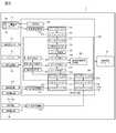
- FIG. 3is a block diagram showing a functional configuration of the fatigue detection apparatus 1.
- the fatigue detection device 1detects fatigue by being attached to the neck (neck) (see FIG. 2), and is elastically attached so as to sandwich the neck from the back side of the user's neck.
- a substantially U-shaped (or substantially C-shaped) neck band 13(corresponding to the mounting member described in the claims) and both ends of the neck band 13 are in contact with both sides of the user's neck.
- a pair of sensor units 11 and 12biological electrodes 15C and 15D and photoelectric pulse wave sensor 20
- a rear side of the user's necksubcutaneously a mitral cap
- living body electrodes 15A and 15Bthat are in contact with the region having the muscle.
- the neckband 13can be worn along the circumferential direction of the user's neck. That is, as shown in FIG. 2, the neckband 13 is worn along the back of the user's neck from one side of the user's neck to the other side of the neck. More specifically, the neck band 13 includes, for example, a belt-shaped plate spring and a rubber coating that covers the periphery of the plate spring. Therefore, the neckband 13 is biased so as to be contracted inward, and when the user wears the neckband 13, the neckband 13 (sensor units 11 and 12 (biological electrodes 15C and 15D and the photoelectric pulse wave sensor). 20) and the biomedical electrodes 15A, 15B) are held in contact with the neck of the user.
- the sensor parts 11 and 12are pressed by the flexibility of the neckband 13, the contact with the skin is stabilized. Further, by allowing the sensor units 11 and 12 to protrude slightly ahead of the neck (neck), the neckband 13 can be adhered to the skin without the neckband 13 being detached from the neck.
- the living body electrodes 15A and 15Bare attached to a substantially central portion in the longitudinal direction of the neckband 13 and a position symmetrical to the center line. Therefore, when the neckband 13 is attached to the user's neck, the biomedical electrodes 15A and 15B are arranged so as to come into contact with the neck at a position where the trapezius muscle on the back side of the user's neck is located.
- the biological electrodes 15A and 15Bare electrodes (myoelectric electrodes) that mainly detect trapezius myoelectric signals.
- the trapezius muscleespecially the upper part of the trapezius muscle
- the neckneck
- Examples of the living body electrodes 15A and 15Binclude, for example, silver / silver chloride, conductive gel, conductive rubber, conductive plastic, metal (stainless steel, Au, etc. that are resistant to corrosion and less metal allergy), conductive cloth, and metal surface.
- a capacitive coupling electrode coated with an insulating layercan be used.
- the conductive clothfor example, a woven fabric, a knitted fabric or a non-woven fabric made of conductive yarn having conductivity is used.
- the conductive yarnfor example, a resin yarn whose surface is plated with Ag, a carbon nanotube-coated one, or a conductive polymer such as PEDOT is used.
- a conductive cloth formed in a rectangular planar shapeis used as the biological electrodes 15A and 15B.
- Each of the pair of biological electrodes 15 ⁇ / b> A and 15 ⁇ / b> Bis connected to the signal processing unit 31, and outputs biological signals mainly including trapezius myoelectric signals to the signal processing unit 31.
- the sensor units 11 and 12have a pair of biological electrodes 15C and 15D. Therefore, when the neckband 13 is attached to the user's neck, the living body electrodes 15C and 15D are placed on the left and right sides of the user's neck (that is, where there are no trapezius muscles and relatively little electromyogram signal). ) In contact with the neck.
- the biological electrodes 15C and 15Dare electrodes (electrocardiographic electrodes) that mainly detect an electrocardiographic signal.
- the biological electrodes 15C and 15Dfor example, silver / silver chloride, conductive gel, conductive rubber, conductive plastic, and metal (stainless steel, Au, etc. are resistant to corrosion and have little metal allergy, like the biological electrodes 15A and 15B.
- a conductive cloth, a capacitive coupling electrode having a metal surface coated with an insulating layer, and the likecan be used.
- a conductive cloth formed in a rectangular planar shapeis used as the biological electrodes 15C and 15D.
- Each of the pair of biological electrodes 15C and 15Dis connected to the signal processing unit 31 and outputs a biological signal mainly including an electrocardiogram signal to the signal processing unit 31.
- the sensor unit 12is provided with an acceleration sensor 22 for detecting the acceleration of the subject's neck (that is, whether or not the neck is moving).
- the sensor unit 12is also connected to the signal processing unit 31 and outputs the detected acceleration signal to the signal processing unit 31.
- a gyro sensor or the likemay be used instead of the acceleration sensor.
- a photoelectric pulse wave sensor 20that has a light emitting element 201 and a light receiving element 202 in the vicinity of the acceleration sensor 22 and detects a photoelectric pulse wave signal is disposed on the inner surface of the sensor unit 12 (the surface in contact with the neck). It is installed.
- the photoelectric pulse wave sensor 20is a sensor that optically detects a photoelectric pulse wave signal using the light absorption characteristic of blood hemoglobin.
- the light emitting element 201emits light according to a pulsed drive signal output from a drive unit 350 of the signal processing unit 31 described later.
- a drive unit 350 of the signal processing unit 31for example, an LED, a VCSEL (Vertical Cavity Surface Emitting LASER), or a resonator type LED can be used.
- the driving unit 350generates and outputs a pulsed driving signal for driving the light emitting element 201.
- the light receiving element 202outputs a detection signal corresponding to the intensity of light irradiated from the light emitting element 201 and transmitted through the neck or reflected from the neck.
- a photodiode or a phototransistoris preferably used as the light receiving element 202.
- a photodiodeis used as the light receiving element 202.
- the light receiving element 202is connected to the signal processing unit 31, and a detection signal (photoelectric pulse wave signal) obtained by the light receiving element 202 is output to the signal processing unit 31.
- a battery(not shown) that supplies electric power to the photoelectric pulse wave sensor 20, the signal processing unit 31, the wireless communication module 60, and the like is housed in one sensor unit 11. Inside the other sensor unit 12, there is a signal processing unit 31 and biological information such as fatigue information (fatigue judgment result), measured myoelectric signal, electrocardiogram signal, photoelectric pulse wave signal, and pulse wave propagation time.
- a wireless communication module 60 for transmitting to an external deviceis accommodated.
- the two pairs of living body electrodes 15A and 15B, the living body electrodes 15C and 15D, and the photoelectric pulse wave sensor 20are connected to the signal processing unit 31, and detected biological signals (myoelectric signal, electrocardiographic signal, and Photoelectric pulse wave signal) is input to the signal processing unit 31.
- the acceleration sensor 22is also connected to the signal processing unit 31, and the detected acceleration signal is input to the signal processing unit 31.
- the signal processing unit 31acquires a myoelectric component (or an index value indicating the magnitude of the myoelectric component) from a biological signal mainly including trapezius myoelectric signals detected by the living body electrodes 15A and 15B.
- the fatigue stateis determined according to the myoelectric component (details will be described later).
- the signal processing unit 31processes a biological signal mainly including an electrocardiographic signal detected by the biological electrodes 15C and 15D to measure a heart rate, a heartbeat interval, and the like, and an input photoelectric pulse wave signal To measure the pulse rate and pulse interval. Further, the signal processing unit 31 measures the pulse wave propagation time from the time difference between the detected R wave peak of the electrocardiogram signal (electrocardiogram) and the peak of the first photoelectric pulse wave signal (pulse wave).
- the signal processing unit 31includes biological signal amplification units 311 and 311B, a pulse wave signal amplification unit 321, first signal processing units 310 and 310B, a second signal processing unit 320, peak detection units 316 and 326, and peak correction units 318 and 328. , A pulse wave transit time measurement unit 330, a frequency analysis unit 331, a myoelectric component acquisition unit 332, and a fatigue determination unit 333.
- the first signal processing units 310 and 310Binclude analog filters 312, 312B, A / D converters 313, 313B, and digital filters 314, 314B.
- the second signal processing unit 320includes an analog filter 322, an A / D converter 323, a digital filter 324, and a second-order differentiation processing unit 325.
- the myoelectric component acquisition unit 332 and the fatigue determination unit 333temporarily store various data such as a CPU that performs arithmetic processing, a ROM that stores programs and data for causing the CPU to execute each processing, and arithmetic results. It is composed of a RAM for storing. That is, the functions of the above-described units are realized by executing the program stored in the ROM by the CPU.
- the biological signal amplifying unit 311is configured by an amplifier using, for example, an operational amplifier, and amplifies the biological signal (mainly the trapezius myoelectric signal) detected by the pair of biological electrodes 15A and 15B.
- the biological signal (myoelectric signal) amplified by the amplification unit 311is output to the first signal processing unit 310.
- the biological signal amplifier 311Bis also configured by an amplifier using, for example, an operational amplifier, and amplifies the biological signals (electrocardiogram signal and myoelectric signal) detected by the pair of biological electrodes 15C and 15D.
- the biological signal (electrocardiogram signal and myoelectric signal) amplified by the amplification unit 311is output to the first signal processing unit 310B.
- the pulse wave signal amplifying unit 321is configured by an amplifier using an operational amplifier, for example, and amplifies the photoelectric pulse wave signal detected by the photoelectric pulse wave sensor 20.
- the photoelectric pulse wave signal amplified by the amplification unit 321is output to the second signal processing unit 320.
- the first signal processing unit 310includes the analog filter 312, the A / D converter 313, and the digital filter 314, and the biological signal (mainly trapezius muscle) amplified by the biological signal amplification unit 311.
- the pulsation component(including the myoelectric component) is extracted by performing a filtering process on the electric signal).
- the first signal processing unit 310Bincludes the analog filter 312B, the A / D converter 313B, and the digital filter 314B, and the biological signal (electrocardiographic signal) amplified by the biological signal amplification unit 311B.
- a myoelectric signala pulsation component (including myoelectric component) is extracted by performing a filtering process.
- the second signal processing unit 320includes the analog filter 322, the A / D converter 323, the digital filter 324, and the second-order differentiation processing unit 325, and the photoelectric pulse amplified by the amplification unit 321.
- a pulsating componentis extracted by applying filtering processing and second-order differentiation processing to the wave signal.
- the analog filters 312, 312B, and 322 and the digital filters 314, 314B, and 324remove components (noise) other than the frequency that characterizes the electrocardiogram signal (including the myoelectric signal) and the photoelectric pulse wave signal, and the S / Filtering is performed to improve N. More specifically, the ECG signal is generally dominated by a frequency component of 0.1 to 200 Hz, and the photoelectric pulse wave signal is dominated by a frequency component of 0.1 to several tens of Hz.
- the analog filter 312, 312B, 322 and the digital filters 314, 314B, 324are subjected to filtering processing, and the S / N is improved by selectively allowing only signals in the above frequency range to pass.
- analog filters 312, 312B, 322 and the digital filters 314, 314B, 324are not necessarily provided, and only one of the analog filters 312, 312B, 322 and the digital filters 314, 314B, 324 may be provided. Good.
- the electrocardiogram signal subjected to the filtering process by the analog filter 312B and the digital filter 314Bis output to the peak detection unit 316.
- the photoelectric pulse wave signal subjected to the filtering process by the analog filter 322 and the digital filter 324is output to the second-order differentiation processing unit 325.
- the second-order differentiation processing unit 325obtains a second-order differential pulse wave (acceleration pulse wave) signal by second-order differentiation of the photoelectric pulse wave signal.
- the acquired acceleration pulse wave signalis output to the peak detector 326.
- the peak (rising point) of the photoelectric pulse waveis not clearly changed and may be difficult to detect. Therefore, it is preferable to detect the peak by converting it to an acceleration pulse wave.
- a second-order differential processing unit 325is provided. Is not essential and may be omitted.
- the peak detection unit 316detects the peak (R wave) of the electrocardiographic signal that has been subjected to signal processing by the first signal processing unit 310B (the pulsating component has been extracted).
- the peak detection unit 326detects the peak of the photoelectric pulse wave signal (acceleration pulse wave) subjected to the filtering process by the second signal processing unit 320.
- Each of the peak detection unit 316 and the peak detection unit 326performs peak detection within the normal range of the heartbeat interval and the pulse interval, and information on the peak time, peak amplitude, and the like for all detected peaks is stored in the RAM or the like. save.
- the peak correction unit 318obtains the delay time of the electrocardiogram signal in the first signal processing unit 310B (analog filter 312B, A / D converter 313B, digital filter 314B). The peak correction unit 318 corrects the peak of the electrocardiogram signal detected by the peak detection unit 316 based on the obtained delay time of the electrocardiogram signal. Similarly, the peak correction unit 328 obtains the delay time of the photoelectric pulse wave signal in the second signal processing unit 320 (analog filter 322, A / D converter 323, digital filter 324, second-order differentiation processing unit 325).
- the peak correction unit 328corrects the peak of the photoelectric pulse wave signal (acceleration pulse wave signal) detected by the peak detection unit 326 based on the obtained delay time of the photoelectric pulse wave signal.
- the corrected peak of the electrocardiogram signal and the corrected peak of the photoelectric pulse wave signal (acceleration pulse wave)are output to the pulse wave propagation time measurement unit 330. Note that providing the peak correction unit 318 is not essential and may be omitted.
- the pulse wave propagation time measurement unit 330is configured to detect an interval (time difference) between the R wave peak of the electrocardiogram signal corrected by the peak correction unit 318 and the peak of the photoelectric pulse wave signal (acceleration pulse wave) corrected by the peak correction unit 328. ) To determine the pulse wave propagation time.
- the pulse wave propagation time measurement unit 330calculates, for example, a heart rate, a heartbeat interval, a heartbeat interval change rate, and the like from an electrocardiogram signal in addition to the pulse wave propagation time. Similarly, the pulse wave propagation time measurement unit 330 calculates a pulse rate, a pulse interval, a pulse interval change rate, and the like from the photoelectric pulse wave signal (acceleration pulse wave).
- the frequency analysis unit 331performs frequency analysis on a biological signal (mainly including the myoelectric signal of the trapezius muscle) obtained by the pair of biological electrodes 15A and 15B and subjected to the filtering process by the signal processing unit 310, and performs frequency spectrum analysis. To get. That is, the frequency analysis unit 331 functions as a frequency analysis unit described in the claims. Examples of the frequency analysis method include a fast Fourier transform method (FFT method), a maximum entropy method (MEM method), and a wavelet method.
- FFT methodfast Fourier transform method
- MEM methodmaximum entropy method
- wavelet methoda wavelet method
- the frequency component of electrocardiogramis particularly high at 0.25 to 30 Hz. Since the frequency component of the electrocardiogram waveform has a frequency component corresponding to the heart rate, a peak in the range of 0.25 to 1.5 Hz corresponding to the heart rate (40 to 240 beats / min) and a peak of its harmonics are included. Have. There are also frequency components of the waveform itself, but there are many components below 30 Hz. Note that the frequency band where the frequency component of the photoelectric pulse wave is particularly large is the same as that of the electrocardiogram, but the frequency side is lower than that of the electrocardiogram. On the other hand, myoelectric signals have a wide frequency component, and there are many ratios of signals of 100 Hz or higher.
- the frequency analysis unit 331determines that the acceleration of the neck detected by the acceleration sensor 22 is equal to or greater than a predetermined threshold (that is, when the neck moves and body motion noise is expected to increase).
- the frequency analysis of the above-described biological signalsis stopped. In other words, when there is body movement, noise is likely to be applied, and the accuracy of the required myoelectric component may be reduced.
- the acceleration sensor 22determines a state in which the user has little movement, and performs a frequency analysis of the biological signal only when such a state continues for a predetermined time, and the frequency analysis result (frequency spectrum) ) To determine the fatigue state.
- the frequency analysis result (frequency spectrum) acquired by the frequency analysis unit 331is output to the myoelectric component acquisition unit 332.
- the myoelectric signalhas a wide frequency component, whereas the electrocardiographic signal has many components of 30 Hz or less. Therefore, the myoelectric component acquisition unit 332 has the first frequency in the first frequency band (for example, 10 to 20 Hz) in which the ratio of the myoelectric component to the electrocardiographic component is low (the electrocardiographic component is large relative to the myoelectric component).
- the power value of the spectrum and the second frequency in the second frequency band(for example, 30 to 50 Hz) in which the ratio of the myoelectric component is higher than the first frequency band (the electrocardiographic component is smaller than the myoelectric component) Obtain the power value of the spectrum.
- the myoelectric component acquisition unit 332acquires the ratio of the power value of the second frequency spectrum to the power value of the first frequency spectrum (hereinafter also referred to as “myoelectric component ratio”). That is, the myoelectric component acquisition unit 332 functions as the myoelectric component acquisition unit described in the claims.
- the bioelectric signal(myoelectric signal) is acquired in a state where the myoelectric component of the trapezius muscle is relatively small (a state equal to or less than a predetermined reference value) after wearing, and the myoelectric component is obtained based on this to obtain the muscle signal. Accurate calculation of the electric component can be performed.
- the state where the myoelectricity of the trapezius muscle is relatively smallis a state where the head is not supported by the neck, such as a state where the head rests on the headrest or a supine position. In this state after wearing, a biological signal (myoelectric signal) is acquired and used as a reference for calculating the myoelectric component (that is, calibration is performed).
- the myoelectric component acquisition unit 332is used when the acceleration of the neck detected by the acceleration sensor 22 is equal to or higher than a predetermined threshold (that is, when the neck moves and body motion noise is expected to increase). Stops acquiring the above-described myoelectric component ratio.
- the myoelectric component ratio acquired by the myoelectric component acquisition unit 332is output to the fatigue determination unit 333.
- the fatigue determination unit 333determines that the user is fatigued when the myoelectric component ratio acquired by the myoelectric component acquisition unit 332 is equal to or greater than a predetermined reference value (fatigue reference value). That is, the fatigue determination unit 333 functions as fatigue determination means described in the claims. At that time, the fatigue determination unit 333 determines that the ratio of the time during which the myoelectric component ratio is equal to or higher than the reference value within the predetermined time is equal to or higher than the predetermined ratio, or (and) the myoelectric component ratio is When the state above the reference value continues for a predetermined time (for example, several minutes) or more, it is determined that the user is tired. That is, primary force may be applied to the cervix even in a non-fatigue state.
- a predetermined reference valuefor example, several minutes
- the fatigue determination unit 333determines that the neck acceleration detected by the acceleration sensor 22 is equal to or greater than a predetermined threshold (that is, when the neck moves and body motion noise is expected to increase). Stop fatigue assessment.
- the fatigue detection device 1informs the user that the user is in a fatigued state through a speaker (or buzzer) 70 (warning). To do). That is, the speaker (or buzzer) 70 functions as the presenting means described in the claims.
- the fatigue detection device 1is connected to a PC (personal computer), a portable music player having a display, a smartphone, or the like via the wireless communication module 60. It has a function to transmit and display information (fatigue judgment result).
- the acquired datasuch as fatigue information (fatigue judgment result) is stored and stored in, for example, the RAM described above, and output to a PC or the like for confirmation after the measurement is completed. Good. Furthermore, it can also be set as the structure which performs fatigue determination with PC, a smart phone, etc. which were connected by radio
- the neck heating unit 80increases the temperature of the neck by heating the neck (around the neck) when the fatigue determination unit 333 determines that the user is tired. That is, the neck heating unit 80 functions as a heating unit described in the claims.
- the neck heating unit 80warms the neck when it is determined that the user is tired. At that time, the neck heating unit 80 adjusts the output so that the temperature of the neck increases as the deviation between the myoelectric component ratio and the reference value increases. On the other hand, when it is determined that the user is not fatigued, the neck heating unit 80 maintains the state at that time or weakens the degree of heating.
- Examples of the heating method by the neck heating unit 80include a method using an electric heater or the like. More specifically, for example, it is preferable that the biological electrodes 15A to 15D, the insulating layer, and the high resistance layer of the electric heater are laminated in order. In this case, the heat generated by passing a current through the high resistance layer of the electric heater is transmitted to the neck of the user through the insulating layer and the biological electrodes 15A to 15D. In addition, it is preferable to provide a temperature control by limiting the temperature adjustment or providing a temperature sensor so that the user does not feel uncomfortable.
- FIG. 4is a flowchart showing a processing procedure of fatigue detection processing by the fatigue detection device 1.
- the process shown in FIG. 4is repeatedly executed mainly at a predetermined timing by the signal processing unit 31.
- step S100When the fatigue detection device 1 is attached to the neck, and the sensor units 11 and 12 (15C and 15D and the photoelectric pulse wave sensor 20) and the biological electrodes 15A and 15B come into contact with the neck, in step S100, the biological electrodes 15A and 15A, A biological signal mainly including a myoelectric signal detected by 15B, a biological signal mainly including an electrocardiographic signal detected by the biological electrodes 15C and 15D, and a photoelectric pulse wave signal detected by the photoelectric pulse wave sensor 20 are read. .
- a filtering processis performed on the biological signal (myoelectric signal, electrocardiogram signal) and the photoelectric pulse wave signal read in step S100. Further, the acceleration pulse wave is obtained by second-order differentiation of the photoelectric pulse wave signal.
- step S104the wearing state of the fatigue detection device 1 is determined based on the amount of light received by the photoelectric pulse wave sensor 20. That is, the photoelectric pulse wave sensor 22 receives the light irradiated from the light emitting element 201, transmitted through the living body / reflected by the living body, and returned by the light receiving element 202, and detects the fluctuation of the light amount as a photoelectric pulse wave signal. Therefore, the amount of received signal light decreases when the device is not properly mounted. Therefore, in step S104, a determination is made as to whether the amount of received light is equal to or greater than a predetermined value. If the received light amount is greater than or equal to the predetermined value, the process proceeds to step S108.
- step S106when the amount of received light is less than the predetermined value, it is determined as a mounting error, and mounting error information (warning information) is output in step S106. Thereafter, the process is temporarily exited.
- a method using the amplitude of the photoelectric pulse wave signal, the baseline stability of the electrocardiogram waveform, the noise frequency component ratio, or the likeis adopted. You can also.
- step S108the peak of the electrocardiogram signal and photoelectric pulse wave signal (acceleration pulse wave signal) is detected. Then, the time difference (peak time difference) between the R wave peak of the detected electrocardiogram signal and the peak of the photoelectric pulse wave signal (acceleration pulse wave) is calculated.
- step S110the delay time (shift amount) of each of the R wave peak of the electrocardiogram signal and the peak of the photoelectric pulse wave signal (acceleration pulse wave) is obtained, and based on the obtained delay time, The time difference (peak time difference) between the R wave peak of the signal and the peak of the photoelectric pulse wave signal (acceleration pulse wave) is corrected.
- step S112it is determined whether or not the peak time difference corrected in step S110 is a predetermined time (for example, 0.01 sec.) Or more. If the peak time difference is greater than or equal to the predetermined time, the process proceeds to step S116. On the other hand, when the peak time difference is less than the predetermined value, error information (noise determination) is output in step S114, and then the process is temporarily exited.
- a predetermined timefor example, 0.01 sec.
- step S116the peak time difference calculated in step S108 is determined as the pulse wave propagation time, and the pulse wave interval is acquired.
- step S118whether or not the neck acceleration detected by the acceleration sensor 22 is equal to or greater than a predetermined threshold (that is, whether or not the neck moves and body motion noise increases). Judgment is made. If the neck acceleration is less than the predetermined threshold value, the process proceeds to step S122. On the other hand, when the cervical acceleration is equal to or greater than the predetermined threshold value, body motion error information is output in step S120, and then the process is temporarily exited.
- a predetermined thresholdthat is, whether or not the neck moves and body motion noise increases.
- step S122the biological signal including the myoelectric signal mainly of the trapezius muscle that has been detected by the biological electrodes 15A and 15B and subjected to the filtering process is subjected to frequency analysis to obtain a frequency spectrum.
- step S124the first frequency spectrum in the first frequency band (for example, 10 Hz or more and 20 Hz or less) in which the ratio of the myoelectric component to the electrocardiographic component is low (the electrocardiographic component is large relative to the myoelectric component).
- Ratio of the power value of the second frequency spectrum in the second frequency band(for example, 30 Hz to 50 Hz) with a high myoelectric component ratio to the power value (the electrocardiographic component is less than the myoelectric component) (myoelectric component) Ratio) is acquired.
- the myoelectric component ratio acquired in step S124is stored in time series.
- step S1208whether or not the acquired myoelectric component ratio is greater than or equal to a reference value and the time ratio of the state is greater than or equal to a predetermined ratio, or (and) the myoelectric component ratio is greater than or equal to a reference value
- a determinationis made as to whether or not has continued for a predetermined time or more.
- the said conditionsare satisfied, it determines with having been fatigued and a process transfers to step S130.
- the conditionis not satisfied, it is determined that the user is not fatigued, and the process proceeds to step S132.
- step S130the user is informed (warned) of the fatigue state by an alarm sound or voice.
- the neck warming unit 80is driven to warm the neck, thereby relieving / reducing fatigue of the user. Thereafter, the process is temporarily exited.
- step S132the operating state of the neck heating unit 80 is maintained without being changed (or the operating state is relaxed). Thereafter, the process is temporarily exited.
- the neckband 13when the neckband 13 is attached to the neck of the user, the neck and the neck at the position where the trapezius muscle on the back side of the user is located.
- Biological electrodes 15A and 15Bare attached to the neckband 13 so as to be in contact with each other.
- the living body electrodes 15A and 15Bbehind the neck (neck) where the trapezoid muscle is under the skin, the myoelectric signal (biological signal) of the trapezius muscle that causes shoulder fatigue. Can be obtained with good S / N.
- the myoelectric component acquired from the biological signal (myoelectric signal) acquired with good S / N by the living body electrodes 15A and 15Bit is determined whether or not the patient is fatigued. As a result, it becomes possible to detect whether or not the user is tired more accurately and stably.
- a biological signal mainly including the myoelectric signal of the trapezius muscleis acquired from the rear side of the user's neck, subjected to frequency analysis, and from the frequency analysis result (frequency spectrum),
- the myoelectric component ratiois high with respect to the power value of the first frequency spectrum in the first frequency band (for example, 10 Hz or more and 20 Hz or less) in which the electric component ratio is low (the electrocardiographic component is greater than the myoelectric component).
- the ratio (myoelectric component ratio) of the power value of the second frequency spectrum in the second frequency bandfor example, 30 Hz to 50 Hz having a smaller electrocardiographic component than the component is acquired.
- the myoelectric component ratio and the reference valueare compared to determine whether or not the user is fatigued.
- the myoelectric component ratioincreases as the myoelectric component increases, the myoelectric component can be accurately obtained.
- the determinationis made, it is possible to detect more accurately and stably whether or not the vehicle is resistant to noise and fatigued. In this case, it is possible to simply evaluate fatigue simply by attaching the neckband type fatigue detection device 1 to the neck.
- the power of the 1st frequency spectrum in the 1st frequency band(for example, 10 Hz or more and 20 Hz or less) with a low myoelectric component ratio (a lot of electrocardiographic components with respect to the myoelectric component) is used for fatigue determination.
- the ratio of the power value of the second frequency spectrum in the second frequency band(for example, 30 Hz or more and 50 Hz or less) having a high myoelectric component ratio with respect to the value (the electrocardiographic component is less than the myoelectric component)
- the power value of the frequency spectrum in the second frequency band of the biological signal with few myoelectric signals acquired by the biological electrodes 15C and 15Dmay be used instead of the first frequency band. .
- the predetermined timewhen it continues for the above, it is determined that the user is tired. Therefore, for example, when it is in a temporary tension state (when the force is temporarily applied to the neck (trapezoid muscle)), it can be prevented from being determined to be tired, It is possible to improve the accuracy of fatigue detection.
- the fatigue determinationis performed. Since it is stopped, erroneous detection due to body movement can be prevented, and fatigue can be detected more accurately.
- the living body electrodes 15C and 15Dare in contact with the neck at a position where the user's trapezius muscle is not present. Since the bioelectrodes 15C and 15D are attached to the band 13, for example, by placing the bioelectrodes 15C and 15D away from the trapezius muscle (for example, from the side of the neck (neck) to the front), An electrocardiographic waveform with few electric signals can be obtained. In this way, an electrocardiographic signal can also be measured simultaneously. Therefore, together with the presence or absence of fatigue, for example, biological information such as heart rate and heart rate interval can be measured simultaneously.
- the userwhen it is determined that the user is in a fatigued state, the user is informed (warned) of the fatigued state by an alarm sound or voice. Therefore, it is possible to inform the user that the user is tired, and it is possible to prevent the user from being in an excessive fatigue state.
- the neckwhen the user is fatigued, the neck (neck) is heated, so that fatigue can be reduced / reduced.
- the necksince the user's neck is heated via the living body electrodes 15A to 15D, it is not necessary to provide a separate heating portion.
- the biomedical electrodes 15A to 15Dare in contact with the neck of the user, the neck can be reliably and efficiently heated.
- the configurationincludes four (two pairs) biological electrodes 15A to 15D, but the configuration includes three biological electrodes 15A, 15B, and 15D. You can also.
- FIG. 5is a block diagram illustrating a functional configuration of the fatigue detection device 2.
- the same or equivalent components as those in the first embodimentare denoted by the same reference numerals.
- the fatigue detection device 2according to the first embodiment described above is that the fatigue detection device 2 has only three biological electrodes 15A, 15B, and 15D, that is, does not have the biological electrode 15C. Is different. Other configurations are the same as or similar to those of the fatigue detection device 1 described above, and thus detailed description thereof is omitted here.
- the three biological electrodes 15A, 15B and 15Dare composed of one common electrode 15A and two biological electrodes 15B and 15D which are paired with the common electrode 15A, respectively.
- a biological signal(myoelectric signal and electrocardiographic signal) is detected by the combination of the common electrode 15A and the biological electrode 15B and the combination of the common electrode 15A and the biological electrode 15D.
- the biological electrodes 15A and 15Bare arranged such that when the neckband 13 is attached to the neck of the user, the neckband 13 comes into contact with the neck at a position where the trapezius muscle on the back side of the user's neck is located. Is attached.
- the living body electrode 15D(sensor unit 11) is arranged such that when the neckband 13 is attached to the neck of the user, the neckband 13 is in contact with the neck at a position where the user's trapezius muscle is not present. Is attached.
- the living body electrodes 15A and 15Bare mainly living body electrodes (myoelectric electrodes) for acquiring myoelectric signals of trapezius muscles.
- the living body electrodes 15A and 15Dare mainly living body electrodes (electrocardiographic electrodes) for acquiring an electrocardiographic signal.
- the biological signal mainly including the trapezius myoelectric signal detected by the biological electrodes 15 ⁇ / b> A and 15 ⁇ / b> Bis output to the biological signal amplifier 311.
- a biological signal including an electrocardiogram signal and a myoelectric signal detected by the biological electrodes 15 ⁇ / b> A and 15 ⁇ / b> Dis output to the biological signal amplifier 311. Since other configurations are the same as or similar to those of the first embodiment described above, detailed description thereof is omitted here.
- the trapezius muscle on the back side of the user's neckis Since it is attached to the neckband 13 so as to come into contact with the neck at a certain position, it is possible to acquire the myoelectric signal (biological signal) of the trapezius that causes fatigue of the shoulder with good S / N. .
- the at least one electrodeis in contact with the neck at the position where the trapezius muscle on the back side of the user is located. Further, it is preferably attached to the neckband 13.
- the myoelectric signalis mainly detected by the living body electrodes 15A and 15B, and the electrocardiographic signal and the myoelectric signal are detected by the living body electrodes 15B and 15C.
- the myoelectric signalis mainly detected by the living body electrodes 15A, 15C (or 15B, 5D), and the living body Electrocardiographic signals are mainly detected by the electrodes 15C and 15D.
- the living body electrodes 15A and 15Dinclude a myoelectric signal and an electrocardiographic signal.
- a myoelectric signal and an electrocardiographic signalare separated by detecting the signal and performing the above-described processing.
- the substantially U-shaped neckband 13 that is mounted so as to sandwich the neck from the back side of the user's neckis used as the mounting member, but forms other than the neckband may be employed.
- FIG. 6Ais a rear view showing the appearance of the fatigue detection device 3.
- FIG. 2Bis a front view showing the appearance of the fatigue detection device 3.
- FIG. 7is a perspective view showing the appearance (use state) of the fatigue detection device 3. 6 and 7, the same or equivalent components as those in the first embodiment are denoted by the same reference numerals.
- the fatigue detection device 3is a flexible mounting body part 16 having a substantially strip shape as a mounting member, and two adhesive parts attached to both ends on the back side of the mounting body part 16.
- Each adhesive part 17has conductivity in addition to adhesiveness, and also functions as the above-described biological electrode (hereinafter, the adhesive part 17 may also be referred to as “biological electrode 17”).
- the adhesive portions (biological electrodes) 17A and 17Bare configured so that the trapezius muscles on the back side of the user's neck when the mounting main body 16 (fatigue detection device 3) is mounted on the user's neck. It is attached to the mounting body 16 so as to come into contact with the neck at a certain position.
- the adhesive portions (biological electrodes) 17C and 17Dare located at positions where the user's trapezius muscle is not present when the mounting body portion 16 (fatigue detecting device 3) is mounted on the neck portion of the user.
- the left and right side surfacesare attached to the mounting main body 16 so as to come into contact with the neck.
- the adhesive portions (biological electrodes) 17A and 17Bare biological electrodes (myoelectric electrodes) for mainly acquiring myoelectric signals of trapezius muscles.
- the adhesion parts (bioelectrodes) 17C and 17Dare bioelectrodes (electrocardiographic electrodes) mainly for acquiring electrocardiographic signals.
- the adhesive part (bioelectrode) 17for example, a biogel electrode is preferably used.
- the adhesive part 17is good also as a structure in which only one part has electroconductivity.
- the detection main body 18 in which the photoelectric pulse wave sensor 20, the signal processing unit 31, the wireless communication module 60, the battery, and the like are housedis attached to the central portion on the surface side of the mounting main body portion 16.
- the living body electrodes 17A and 17B and the living body electrodes 17C and 17Dare electrically connected to the detection main body 18 (signal processing unit 31).
- a holeis formed in the mounting main body 16 at a position corresponding to the photoelectric pulse wave sensor 20, and the photoelectric pulse wave sensor 20 is fitted into the hole. That is, when the mounting body 16 (fatigue detection device 3) is mounted on the neck, the photoelectric pulse wave sensor 20 (the light emitting element 201 and the light receiving element 202) is mounted so as to come into contact with the neck skin. Yes.
- the photoelectric pulse wave sensor 20is disposed outside the region where the adhesive portion 17 is attached (see FIG. 6B), but the photoelectric pulse wave sensor 20 is attached to the adhesive portion 17. You may arrange
- the details of the photoelectric pulse wave sensor 20, the signal processing unit 31, the wireless communication module 60, and the likeare as described above, and thus detailed description thereof is omitted here.
- the adhesive portion 17 having adhesivenessis attached to the mounting body portion 16 having flexibility and formed in a substantially strip shape, the mounting body portion is utilized by using the adhesiveness of the adhesive portion 17. 16 can be affixed (attached) to the neck. Moreover, since the adhesion part 17 has electroconductivity and functions as a biological electrode, it is possible to easily detect fatigue simply by attaching (attaching) the attachment main body part 16 to the neck part.
- the fatigue detection devices 1, 2, and 3are provided with the photoelectric pulse wave sensor 20, but may be configured without the photoelectric pulse wave sensor 20.
- a piezoelectric pulse wave sensorinstead of or in addition to the photoelectric pulse wave sensor 20, a piezoelectric pulse wave sensor, an oxygen saturation sensor, a sound sensor (microphone), a displacement sensor, a temperature sensor, a humidity sensor, or the like may be used.
- the pair of sensor portions 11 and 12are attached to both ends of the neckband 13, but the sensor portions 11 and 12 are not necessarily attached to both ends of the neckband. Further, the neckband 13 may be configured such that its length can be adjusted by an adjusting mechanism or the like.
- the fatigue stateis determined based on the myoelectric component ratio acquired from the biological signal, but the fatigue state may be determined based on the myoelectric component amount.
- the myoelectric component acquisition unit 332performs, for example, a frequency band of 30 Hz to 50 Hz with respect to the frequency analysis result (frequency spectrum) by the frequency analysis unit 331 (that is, the myoelectric component is low and has a small electrocardiographic component).
- the ratio of the time during which the myoelectric component amount is equal to or higher than the reference value within the predetermined timeis equal to or higher than the predetermined ratio, or (and) the myoelectric component amount is equal to or higher than the reference value. It is preferable to determine that the state is fatigued when the state continues for a predetermined time or more. Thus, even if the fatigue state is determined based on the myoelectric component amount obtained from the frequency analysis result (frequency spectrum), it is possible to more accurately and stably detect whether or not the user is fatigued. it can.
- the neck warming portion 80when it is determined that the user is tired, the neck warming portion 80 is used to warm the neck (around the neck) and the fatigue is reduced / reduced.
- a neck cooling meansthat cools the neck, or a neck that presses the neck (for example, a pressure is intermittently applied by inflating a built-in bag with a pump). It is good also as a structure which relieves / reduces fatigue using a part press means.
Landscapes
- Health & Medical Sciences (AREA)
- Life Sciences & Earth Sciences (AREA)
- Engineering & Computer Science (AREA)
- Animal Behavior & Ethology (AREA)
- Heart & Thoracic Surgery (AREA)
- Veterinary Medicine (AREA)
- Public Health (AREA)
- General Health & Medical Sciences (AREA)
- Surgery (AREA)
- Physics & Mathematics (AREA)
- Molecular Biology (AREA)
- Biophysics (AREA)
- Pathology (AREA)
- Biomedical Technology (AREA)
- Medical Informatics (AREA)
- Psychiatry (AREA)
- Educational Technology (AREA)
- Developmental Disabilities (AREA)
- Social Psychology (AREA)
- Child & Adolescent Psychology (AREA)
- Psychology (AREA)
- Hospice & Palliative Care (AREA)
- Measurement And Recording Of Electrical Phenomena And Electrical Characteristics Of The Living Body (AREA)
- Measuring Pulse, Heart Rate, Blood Pressure Or Blood Flow (AREA)
- Measurement Of The Respiration, Hearing Ability, Form, And Blood Characteristics Of Living Organisms (AREA)
Abstract
Description
Translated fromJapanese本発明は、疲労検出装置に関する。The present invention relates to a fatigue detection device.
近年、人の疲労を検知する技術が提案されている(例えば特許文献1参照)。ここで、特許文献1には、LF/HF値について疲労度判定基準値データを確立し、脈拍間隔(又は心拍間隔)から算出した被験者のLF/HF値と疲労度判定基準値データとを対比して、疲労度を判定する疲労度の判定処理システムが開示されている。Recently, a technique for detecting human fatigue has been proposed (see, for example, Patent Document 1). Here,
特許文献1に記載の疲労度の判定処理システムでは、例えば、加速度脈波のa-a間隔を最大エントロピー法(MEM)を用いて周波数領域の低周波数成分(LF:約0.04-0.15Hz)と高周波数成分(HF:約0.15-0.40Hz)とに分離し、LF値を被験者の交感神経の働き値、HF値を被験者の副交感神経の働き値としている。この疲労度の判定処理システムによれば、LF/HF値を用いることにより、交感神経機能の亢進を評価することができ、客観的に疲労度を評価することができる。In the fatigue level determination processing system described in
ところで、上述したLF/HF値を用いた疲労度の判定処理システムでは、自律神経(すなわち交感神経及び副交感神経)の状態が安定しているときに脈拍又は心拍等のデータを得る必要があるため、使用者は計測前に例えば5分間程度、安静座位姿勢にて休息することが必要とされる。そして、十分な休息をとった後、そのままの状態で例えば3分間以上(又は例えば100拍以上)、継続的に光電脈波又は心電図の計測を行う必要がある。By the way, in the fatigue determination processing system using the LF / HF values described above, it is necessary to obtain data such as a pulse or a heart rate when the state of the autonomic nerve (that is, the sympathetic nerve and the parasympathetic nerve) is stable. The user is required to rest in a resting posture, for example, for about 5 minutes before measurement. Then, after taking a sufficient rest, it is necessary to continuously measure the photoelectric pulse wave or the electrocardiogram for 3 minutes or more (or 100 beats or more, for example) as it is.
そのため、上述した疲労度の判定処理システムでは、計測前に充分な休息を取ることができない場合や、計測中に安静状態を保てないときには、交感神経が優位になり、正しい疲労状態の評価を行うことができないおそれがあった。また、この疲労度の判定処理システムでは、疲労度の判定精度が、加速度脈波のa-a間隔を正確に取得できるか否かに直接的に影響されるため、ノイズに弱く、ノイズによって(例えば、ノイズをピークと誤判定したり、ピークにノイズが重なってピーク位置がずれたりすることによって)判定精度が低下しやすいという問題があった。そのため、特許文献1に記載の疲労度の判定処理システムでは、疲労しているか否かを精度良く、かつ安定的に検出することが困難であった。Therefore, in the above-described fatigue level determination processing system, when sufficient rest cannot be taken before measurement, or when resting state cannot be maintained during measurement, the sympathetic nerve is dominant, and the correct fatigue state is evaluated. There was a risk that it could not be done. In this fatigue level determination processing system, the fatigue level determination accuracy is directly affected by whether or not the aa interval of the acceleration pulse wave can be accurately acquired. For example, there is a problem that the determination accuracy is likely to be lowered (by misjudging the noise as a peak or when the peak overlaps with the noise and the peak position is shifted). Therefore, in the fatigue level determination processing system described in
本発明は、上記問題点を解消する為になされたものであり、疲労している否かをより精度よく、かつ安定的に検出することが可能な疲労検出装置を提供することを目的とする。The present invention has been made to solve the above-described problems, and an object of the present invention is to provide a fatigue detection device capable of more accurately and stably detecting whether or not the subject is fatigued. .
本発明に係る疲労検出装置は、使用者の頸部の周方向に沿って装着可能な装着部材と、装着部材に取り付けられ、筋電信号を含む生体信号を取得する複数の生体用電極と、生体用電極により取得された生体信号から取得される筋電成分に基づいて、疲労しているか否かを判定する疲労判定手段とを備え、装着部材が使用者の頸部に装着されたときに、使用者の頸部後側の僧帽筋がある位置において頸部と接触するように、上記複数の生体用電極が、装着部材に取り付けられていることを特徴とする。A fatigue detection device according to the present invention includes a mounting member that can be mounted along a circumferential direction of a user's neck, a plurality of biological electrodes that are attached to the mounting member and acquire a biological signal including a myoelectric signal, Fatigue determining means for determining whether or not the user is fatigued based on a myoelectric component acquired from a biological signal acquired by the biological electrode, and when the mounting member is mounted on the neck of the user The plurality of biological electrodes are attached to the mounting member so as to come into contact with the neck at a position where the trapezius muscle on the back side of the user's neck is located.
ところで、出願人は、鋭意研究の結果、肩こりに代表される肩の疲労感の原因となる筋である僧帽筋に力が入ると僧帽筋がある頸部(首)後方の筋電信号量が増加するという知見を得た。ここで、本発明に係る疲労検出装置によれば、装着部材が使用者の頸部に装着されたときに、使用者の頸部後側の僧帽筋がある位置において頸部と接触するように、複数の生体用電極が装着部材に取り付けられている。このように、皮下に僧帽筋がある頸部(首)の後方に生体用電極を配置することで、肩の疲労感の原因となる僧帽筋の筋電信号(生体信号)をS/Nよく取得することができる。そして、該生体用電極によりS/Nよく取得された生体信号(筋電信号)から取得される筋電成分に基づいて、疲労しているか否かが判定される。その結果、疲労している否かをより精度よく、かつ安定的に検出することが可能となる。By the way, as a result of diligent research, the applicant has studied the electromyographic signal behind the neck (neck) where the trapezius muscle is located when force is applied to the trapezius muscle, which is a muscle that causes shoulder fatigue typified by stiff shoulders. The knowledge that the amount increases was obtained. Here, according to the fatigue detection device of the present invention, when the mounting member is mounted on the neck of the user, the neck is in contact with the neck at a position where the trapezius muscle on the back side of the user is located. In addition, a plurality of biological electrodes are attached to the mounting member. In this way, the bioelectric electrode is placed behind the neck (neck) where the trapezoid muscle is under the skin, so that the myoelectric signal (biological signal) of the trapezius that causes fatigue of the shoulder can be obtained as S / N well. Then, based on a myoelectric component acquired from a biological signal (myoelectric signal) acquired with a good S / N by the living body electrode, it is determined whether or not the patient is fatigued. As a result, it becomes possible to detect whether or not the user is tired more accurately and stably.
本発明に係る疲労検出装置は、複数の生体用電極により取得された生体信号を周波数解析して周波数スペクトルを求める周波数解析手段と、周波数解析手段により求められた周波数スペクトルから筋電成分を取得する筋電成分取得手段とを備え、疲労判定手段が、筋電成分取得手段により取得された筋電成分が基準値以上である場合に、疲労していると判定することが好ましい。The fatigue detection device according to the present invention obtains a myoelectric component from a frequency analysis means for obtaining a frequency spectrum by performing frequency analysis on biological signals obtained by a plurality of biological electrodes, and a frequency spectrum obtained by the frequency analysis means. Preferably, the fatigue determination unit determines that the subject is fatigued when the myoelectric component acquired by the myoelectric component acquisition unit is greater than or equal to a reference value.
ところで、頸部(僧帽筋)に力が入っている状態(すなわち頸部(僧帽筋)の筋電信号量が多い状態)が続く場合には、緊張・疲労している状態であると推測することができる。そこで、この場合、使用者の頸部(僧帽筋)から筋電信号を含む生体信号が取得されて、周波数解析され、その周波数解析結果(周波数スペクトル)から筋電成分が取得される。そして、筋電成分と基準値とが比較されて、疲労しているか否かが判定される。このように、頸部(僧帽筋)から取得される筋電信号を利用し、かつ、その周波数解析結果(周波数スペクトル)に基づいて疲労しているか否かを判定するようにしたため、疲労している否かをより精度よく、かつ安定的に検出することが可能となる。By the way, when the state where the neck (trapezoidal muscles) is in force (that is, the state where the neck (trapezoidal muscle) has a large amount of myoelectric signal) continues, Can be guessed. Therefore, in this case, a biological signal including a myoelectric signal is acquired from the user's neck (trapezoid muscle), subjected to frequency analysis, and a myoelectric component is acquired from the frequency analysis result (frequency spectrum). Then, the myoelectric component and the reference value are compared to determine whether or not the user is fatigued. As described above, since the myoelectric signal acquired from the neck (trapezoid muscle) is used and it is determined whether the user is fatigued based on the frequency analysis result (frequency spectrum), the user is fatigued. It is possible to detect more accurately and stably.
本発明に係る疲労検出装置では、疲労判定手段が、所定時間内における、筋電成分が基準値以上の状態の時間の割合が、所定の割合以上になった場合に、疲労していると判定することが好ましい。In the fatigue detection device according to the present invention, the fatigue determination means determines that the user is fatigued when the ratio of the time during which the myoelectric component is equal to or higher than the reference value within a predetermined time is equal to or higher than the predetermined ratio. It is preferable to do.
この場合、筋電成分が基準値以上である状態の時間割合が所定割合以上になった場合に、疲労していると判定される。よって、例えば、一時的な緊張状態にあるような場合(一時的に頸部(僧帽筋)に力が入ったとき)に疲労していると判定してしまうことを防止することができ、疲労検出の精度を向上させることが可能となる。In this case, it is determined that the user is tired when the time ratio in which the myoelectric component is equal to or higher than the reference value is equal to or higher than a predetermined ratio. Therefore, for example, when it is in a temporary tension state (when the force is temporarily applied to the neck (trapezoid muscle)), it can be prevented from being determined to be tired, It is possible to improve the accuracy of fatigue detection.
本発明に係る疲労検出装置では、疲労判定手段が、筋電成分が基準値以上の状態が、所定時間以上継続した場合に、疲労していると判定することが好ましい。In the fatigue detection device according to the present invention, it is preferable that the fatigue determination means determine that the user is fatigued when a state where the myoelectric component is equal to or higher than a reference value continues for a predetermined time or longer.
この場合、筋電成分が基準値以上の状態が所定時間以上継続した場合に、疲労していると判定される。よって、例えば、一時的な緊張状態にあるような場合(一時的に頸部に力が入ったとき)に疲労していると判定してしまうことを防止することができ、疲労検出の精度を向上させることが可能となる。In this case, when the state where the myoelectric component is equal to or higher than the reference value continues for a predetermined time or more, it is determined that the user is tired. Therefore, for example, when it is in a temporary tension state (when a force is temporarily applied to the neck), it can be prevented from being determined to be tired, and the accuracy of fatigue detection can be improved. It becomes possible to improve.
本発明に係る疲労検出装置は、複数の生体用電極により取得された生体信号を周波数解析して周波数スペクトルを求める周波数解析手段と、心電成分に対する筋電成分割合が低い第1の周波数帯域における第1の周波数スペクトルのパワー値に対する、第1の周波数帯域よりも筋電成分割合が高い第2の周波数帯域における第2の周波数スペクトルのパワー値の比率を取得する筋電成分取得手段とを備え、疲労判定手段が、筋電成分取得手段により取得された、第1の周波数スペクトルのパワー値に対する第2の周波数スペクトルのパワー値の比率が基準値以上である場合に、疲労していると判定することも好ましい。The fatigue detection device according to the present invention includes a frequency analysis means for obtaining a frequency spectrum by performing frequency analysis on biological signals acquired by a plurality of biological electrodes, and a first myoelectric component ratio with respect to an electrocardiographic component in a first frequency band. Electromyographic component acquisition means for acquiring the ratio of the power value of the second frequency spectrum in the second frequency band having a higher myoelectric component ratio than the first frequency band to the power value of the first frequency spectrum. The fatigue determination means determines that the user is fatigued when the ratio of the power value of the second frequency spectrum to the power value of the first frequency spectrum acquired by the myoelectric component acquisition means is greater than or equal to a reference value. It is also preferable to do.
この場合、使用者の頸部後側から、筋電信号を含む生体信号が取得されて、周波数解析され、その周波数解析結果(周波数スペクトル)から、心電成分に対する筋電成分の割合が低い(筋電成分に対して心電成分が多い)第1の周波数帯域における第1の周波数スペクトルのパワー値に対する、第1の周波数帯域よりも筋電成分の割合が高い(筋電成分に対して心電成分が少ない)第2の周波数帯域における第2の周波数スペクトルのパワー値の比率が取得される。そして、当該比率と基準値とが比較されて、疲労しているか否かが判定される。ここで、筋電成分が大きくなるほど、上記比率が大きくなるため、筋電成分を精度よく求めることができる。このように、頸部(僧帽筋)から取得される筋電信号を利用し、かつ、その周波数解析結果(周波数スペクトル)から求められた上記比率に基づいて疲労しているか否かを判定するようにしたため、ノイズに強く、疲労している否かをより精度よく、かつ安定的に検出することが可能となる。In this case, a biological signal including a myoelectric signal is acquired from the back side of the user's neck and subjected to frequency analysis. From the frequency analysis result (frequency spectrum), the ratio of the myoelectric component to the electrocardiographic component is low ( The ratio of the myoelectric component to the power value of the first frequency spectrum in the first frequency band is higher than that of the first frequency band (the heart is higher than the myoelectric component). The ratio of the power values of the second frequency spectrum in the second frequency band (with less electrical component) is acquired. Then, the ratio and the reference value are compared to determine whether or not the user is fatigued. Here, since the ratio increases as the myoelectric component increases, the myoelectric component can be obtained with high accuracy. In this way, it is determined whether the user is fatigued based on the ratio obtained from the frequency analysis result (frequency spectrum) using the myoelectric signal acquired from the neck (trapezoid muscle). As a result, it is possible to detect with high accuracy and stability whether noise is strong or fatigued.
本発明に係る疲労検出装置では、疲労判定手段が、所定時間内における、上記比率が基準値以上の状態の時間の割合が、所定の割合以上になった場合に、疲労していると判定することが好ましい。In the fatigue detection device according to the present invention, the fatigue determination means determines that the tire is fatigued when the ratio of the time in which the ratio is equal to or higher than the reference value within a predetermined time is equal to or higher than the predetermined ratio. It is preferable.
この場合、上記比率が基準値以上である状態の時間割合が所定割合以上になった場合に、疲労していると判定される。よって、例えば、一時的な緊張状態にあるような場合(一時的に頸部(僧帽筋)に力が入ったとき)に疲労していると判定してしまうことを防止することができ、疲労検出の精度を向上させることが可能となる。In this case, it is determined that the user is tired when the time ratio in a state where the ratio is equal to or greater than the reference value is equal to or greater than a predetermined ratio. Therefore, for example, when it is in a temporary tension state (when the force is temporarily applied to the neck (trapezoid muscle)), it can be prevented from being determined to be tired, It is possible to improve the accuracy of fatigue detection.
本発明に係る疲労検出装置では、疲労判定手段が、上記比率が基準値以上の状態が、所定時間以上継続した場合に、疲労していると判定することが好ましい。In the fatigue detection device according to the present invention, it is preferable that the fatigue determination means determine that the tire is fatigued when the state where the ratio is equal to or higher than the reference value continues for a predetermined time or longer.
この場合、上記比率が基準値以上の状態が所定時間以上継続した場合に、疲労していると判定される。よって、例えば、一時的な緊張状態にあるような場合(一時的に頸部(僧帽筋)に力が入ったとき)に疲労していると判定してしまうことを防止することができ、疲労検出の精度を向上させることが可能となる。In this case, when the state where the ratio is equal to or higher than the reference value continues for a predetermined time or more, it is determined that the user is tired. Therefore, for example, when it is in a temporary tension state (when the force is temporarily applied to the neck (trapezoid muscle)), it can be prevented from being determined to be tired, It is possible to improve the accuracy of fatigue detection.
また、本発明に係る疲労検出装置は、装着部材に取り付けられ、被験者の頸部の加速度を検出する加速度センサをさらに備え、加速度センサにより検出された加速度が所定のしきい値を超えているときには、疲労判定手段が、疲労しているか否かの判定を停止することが好ましい。The fatigue detection device according to the present invention further includes an acceleration sensor that is attached to the mounting member and detects the acceleration of the neck of the subject, and when the acceleration detected by the acceleration sensor exceeds a predetermined threshold value The fatigue determination means preferably stops determining whether or not the user is fatigued.
このようにすれば、例えば、頸部を動かしている場合(すなわち、頸部を動かしたことにより筋電量が一時的に大きくなった場合や体動ノイズが大きい場合)には、疲労判定が停止されるため、体動に起因する誤検出を防止でき、より精度よく疲労を検出することが可能となる。In this way, for example, when the neck is moved (that is, when the myoelectric amount is temporarily increased due to the movement of the neck or the body motion noise is large), fatigue determination is stopped. Therefore, erroneous detection due to body movement can be prevented, and fatigue can be detected with higher accuracy.
本発明に係る疲労検出装置では、上記複数の生体用電極が、装着部材が使用者の頸部に装着されたときに、僧帽筋がない位置において頸部と接触するように、装着部材に取り付けられた、少なくとも一つの生体用電極を含むことが好ましい。In the fatigue detection device according to the present invention, when the mounting member is mounted on the neck of the user, the plurality of biomedical electrodes are attached to the mounting member so as to contact the neck at a position where there is no trapezius muscle. Preferably, it includes at least one biological electrode attached.
この場合、上記複数の生体用電極が、装着部材が使用者の頸部に装着されたときに、僧帽筋がない位置において頸部と接触するように、装着部材に取り付けられた、少なくとも一つの生体用電極を含むため、僧帽筋の筋電信号が多い電極配置と少ない電極配置とを組み合わせることで筋電成分測定の精度を上げることができる。In this case, at least one of the plurality of biomedical electrodes is attached to the attachment member so as to come into contact with the neck at a position where the trapezius muscle is not present when the attachment member is attached to the neck of the user. Since it includes two living body electrodes, the accuracy of myoelectric component measurement can be improved by combining an electrode arrangement with a large amount of myoelectric signal of the trapezius muscle and an electrode arrangement with a small amount.
本発明に係る疲労検出装置では、上記複数の生体用電極が、心電信号を含む生体信号を測定するための一対の生体用電極を含み、当該一対の生体用電極の内、少なくとも1つの生体用電極が、装着部材が使用者の頸部に装着されたときに、使用者の僧帽筋がない位置において頸部と接触するように、装着部材に取り付けられていることが好ましい。In the fatigue detection device according to the present invention, the plurality of living body electrodes include a pair of living body electrodes for measuring a living body signal including an electrocardiographic signal, and at least one living body among the pair of living body electrodes. It is preferable that the working electrode is attached to the mounting member such that when the mounting member is mounted on the neck of the user, the electrode contacts the neck at a position where the user's trapezius muscle is not present.
この場合、一対の生体用電極の内、少なくとも1つの生体用電極が、装着部材が使用者の頸部に装着されたときに、使用者の僧帽筋がない位置において頸部と接触するように、装着部材に取り付けられているため、当該生体電極を、例えば、僧帽筋から離れた位置(例えば頸部(首)の横から前方)に配置することで僧帽筋に起因する筋電信号の少ない心電波形を得ることができる。また、このようにすれば、心電信号も同時に計測することができる。そのため、疲労の有無と併せて、例えば、心拍数や心拍間隔等の生体情報を同時に計測することも可能となる。In this case, at least one biological electrode of the pair of biological electrodes comes into contact with the neck at a position where the user's trapezius muscle is not present when the mounting member is mounted on the neck of the user. In addition, since the bioelectrode is attached to the attachment member, for example, by placing the bioelectrode at a position away from the trapezius muscle (for example, from the side of the neck (neck) to the front), the myoelectric signal caused by the trapezius muscle An electrocardiogram with few signals can be obtained. In this way, an electrocardiographic signal can also be measured simultaneously. Therefore, together with the presence or absence of fatigue, for example, biological information such as heart rate and heart rate interval can be measured simultaneously.
本発明に係る疲労検出装置では、上記装着部材がネックバンドであることが好ましい。このようにすれば、ネックバンド型の疲労検出装置を頸部に装着するだけで、簡便に疲労を検出することができる。In the fatigue detection device according to the present invention, the mounting member is preferably a neckband. In this way, it is possible to simply detect fatigue by simply attaching a neckband type fatigue detection device to the neck.
また、本発明に係る疲労検出装置では、上記装着部材が、柔軟性を有し略帯状に形成された装着本体部と、該装着本体部に取り付けられた粘着性を有する粘着部とを有し、該粘着部が、少なくとも一部が導電性を有し、上記生体用電極として機能することが好ましい。Further, in the fatigue detection device according to the present invention, the mounting member has a mounting body portion that is flexible and formed in a substantially band shape, and an adhesive portion that has adhesiveness attached to the mounting body portion. The adhesive part preferably has at least a part of conductivity and functions as the biological electrode.
この場合には、柔軟性を有し略帯状に形成された装着本体部に粘着性を有する粘着部が取り付けられているため、粘着部の粘着性を利用して装着本体部(装着部材)を頸部に貼り付ける(装着する)ことができる。また、粘着部の少なくとも一部が導電性を有し生体用電極として機能するため、装着部材を頸部に貼り付ける(装着する)だけで、簡便に疲労を検出することができる。In this case, since the adhesive portion having adhesiveness is attached to the flexible mounting body portion that is formed in a substantially strip shape, the mounting body portion (mounting member) is attached using the adhesiveness of the adhesive portion. Can be attached (attached) to the neck. In addition, since at least a part of the adhesive portion has conductivity and functions as a biological electrode, it is possible to easily detect fatigue by simply attaching (attaching) the attachment member to the neck portion.
本発明に係る疲労検出装置では、筋電成分取得手段が、装着部材が装着された状態において、筋電成分が比較的少ない状態を基準として、筋電成分のキャリブレーションを行う
ことが好ましい。In the fatigue detection apparatus according to the present invention, it is preferable that the myoelectric component acquisition means calibrate the myoelectric component with reference to a state in which the myoelectric component is relatively small in a state where the mounting member is mounted.
ところで、装着状態が悪い(生体電極と生体(頸部)との接触状態が悪い)とノイズが増え、筋電成分の正確な算出が困難になる。この場合、装着部材の装着後に僧帽筋の筋電成分が比較的少ない状態で生体信号を取得し、これを基準として筋電成分を求めることで、筋電成分の正確な算出を行うことができる。By the way, when the wearing state is bad (the contact state between the biological electrode and the living body (neck)) is poor, noise increases and accurate calculation of the myoelectric component becomes difficult. In this case, it is possible to accurately calculate the myoelectric component by obtaining a biological signal in a state where the myoelectric component of the trapezius muscle is relatively small after the mounting member is mounted, and obtaining the myoelectric component based on this. it can.
本発明に係る疲労検出装置は、疲労状態であると判定された場合に、使用者に疲労状態であることを提示する提示手段をさらに備えることが好ましい。It is preferable that the fatigue detection device according to the present invention further includes a presentation unit that presents the user with the fatigue state when it is determined that the fatigue state is present.
このようにすれば、疲労していることを使用者に知らせることができ、使用者が過度の疲労状態になることを予防することが可能となる。In this way, it is possible to inform the user that they are tired, and it is possible to prevent the user from becoming overly fatigued.
本発明に係る疲労検出装置は、疲労状態であると判定された場合に、頸部を加温する加温手段をさらに備えることが好ましい。It is preferable that the fatigue detection apparatus according to the present invention further includes a heating means for heating the neck when it is determined that the fatigue state is present.
このようにすれば、使用者が疲労しているときに、頸部(僧帽筋)を加温することにより、疲労を緩和・低減することが可能となる。In this way, when the user is tired, it is possible to relieve and reduce fatigue by heating the neck (trapezoid muscle).
本発明に係る疲労検出装置では、上記加温手段が、生体用電極の温度を上げることにより、頸部を加温することが好ましい。In the fatigue detection device according to the present invention, it is preferable that the heating means warms the neck by raising the temperature of the living body electrode.
この場合、生体用電極を介して使用者の頸部(僧帽筋)を加温するため、別途加温部を設ける必要がない。また、生体用電極は使用者の頸部に接触しているため、確実に、かつ効率よく頸部を加温することが可能となる。In this case, since the user's neck (trapezoidal muscle) is heated via the living body electrode, it is not necessary to provide a separate heating portion. In addition, since the biomedical electrode is in contact with the user's neck, the neck can be reliably and efficiently heated.
本発明によれば、疲労している否かをより精度よく、かつ安定的に検出することが可能となる。According to the present invention, it is possible to detect whether or not the user is tired more accurately and stably.
以下、図面を参照して本発明の好適な実施形態について詳細に説明する。なお、図中、同一又は相当部分には同一符号を用いることとする。また、各図において、同一要素には同一符号を付して重複する説明を省略する。Hereinafter, preferred embodiments of the present invention will be described in detail with reference to the drawings. In the drawings, the same reference numerals are used for the same or corresponding parts. Moreover, in each figure, the same code | symbol is attached | subjected to the same element and the overlapping description is abbreviate | omitted.
(第1実施形態)
まず、図1~図3を併せて用いて、第1実施形態に係る疲労検出装置1の構成について説明する。図1は、疲労検出装置1の外観を示す平面図である。図2は、疲労検出装置1の外観(使用状態)を示す斜視図である。また、図3は、疲労検出装置1の機能構成を示すブロック図である。(First embodiment)
First, the configuration of the
疲労検出装置1は、頸部(首筋)に装着することにより疲労を検出するものであり(図2参照)、使用者の頸部の後ろ側から頸部を挟むように弾性的に装着される概略U字形(或は略C字形)のネックバンド13(請求の範囲に記載の装着部材に相当)と、ネックバンド13の両端に配設されることで使用者の頸部の両側に接触する一対のセンサ部11,12(生体用電極15C,15D及び光電脈波センサ20)と、ネックバンド13の略中央部に配設されることで使用者の頸部の後側(皮下に僧帽筋がある領域)に接触する生体用電極15A,15Bとを備えている。The
ネックバンド13は、使用者の頸部の周方向に沿って装着可能なものである。すなわち、ネックバンド13は、図2に示されるように、使用者の一方の頸部側方から他方の頸部側方まで、使用者の頸部後方に沿って装着される。より具体的には、ネックバンド13は、例えば、帯状の板バネと、この板バネの周囲を覆うゴム被覆を有して構成されている。そのため、ネックバンド13は、内側に縮むように付勢されており、使用者がネックバンド13を装着した場合に、ネックバンド13(センサ部11,12(生体用電極15C,15D並びに光電脈波センサ20)及び生体用電極15A,15B)が使用者の頸部に接触した状態で保持される。特に、センサ部11,12は、ネックバンド13の可撓性により押圧がかかるため、皮膚との接触が安定する。また、センサ部11,12を頸部(首)の真横よりも少し前方に出るようにすることで、ネックバンド13は頸部から外れることなく、生体用電極15A,15Bも皮膚に密着できる。The
なお、ゴム被覆としては、生体適合性を有するものを用いることが好ましい。また、ゴム被覆に代えて例えばプラスチックからなる被覆を用いることもできる。ゴム被覆の中には、双方のセンサ部11,12(生体用電極15C,15D並びに光電脈波センサ20)及び生体用電極15A,15Bを電気的に接続するケーブルも配線されている。ここで、ケーブルは、ノイズを低減するために、同軸とすることが望ましい。In addition, it is preferable to use what has biocompatibility as rubber coating. Further, instead of the rubber coating, for example, a coating made of plastic can be used. In the rubber coating, cables for electrically connecting both
生体用電極15A,15Bは、ネックバンド13の長手方向の略中央部、かつ中心線に対して対称な位置に取り付けられている。そのため、ネックバンド13が使用者の頸部に装着されたときに、生体用電極15A,15Bは、使用者の頸部後側の僧帽筋がある位置において頸部と接触するように配置される。生体用電極15A,15Bは、主として僧帽筋の筋電信号を検出する電極(筋電電極)である。ここで、僧帽筋(特に僧帽筋上部線維)は、肩部から頸部(首)につながっている筋であり、長時間の作業によるストレスや目の疲労などの影響を受けやすく、いわゆる肩こりに代表される肩の疲労感の原因となる筋である。The living
生体用電極15A,15Bとしては、例えば、銀・塩化銀、導電ゲル、導電ゴム、導電プラスチック、金属(ステンレス、Au等の腐食に強く金属アレルギーの少ないものが好ましい)、導電布、金属表面を絶縁層でコーティングした容量性結合電極等を用いることができる。ここで、導電布としては、例えば、導電性を有する導電糸からなる織物や編物、不織布が用いられる。また、導電糸としては、例えば、樹脂糸の表面をAgなどでめっきしたものや、カーボンナノチューブ・コーティングを施したもの、PEDOTなどの導電性高分子をコーティングしたものを用いることができる。また、導電性を有する導電性ポリマー糸を用いてもよい。なお、本実施形態では、生体用電極15A,15Bとして、矩形の平面状に形成した導電布を用いた。一対の生体用電極15A,15Bそれぞれは、信号処理部31と接続されており、主として僧帽筋の筋電信号を含む生体信号を信号処理部31へ出力する。Examples of the living
センサ部11,12は、一対の生体用電極15C,15Dを有している。そのため、ネックバンド13が使用者の頸部に装着されたときに、生体用電極15C,15Dは、使用者の頸部の左右側面(すなわち、僧帽筋がなく筋電信号が比較的少ない箇所)において頸部と接触するように配置される。生体用電極15C,15Dは、主として心電信号を検出する電極(心電電極)である。生体用電極15C,15Dとしては、上記生体用電極15A,15Bと同様に、例えば、銀・塩化銀、導電ゲル、導電ゴム、導電プラスチック、金属(ステンレス、Au等の腐食に強く金属アレルギーの少ないものが好ましい)、導電布、金属表面を絶縁層でコーティングした容量性結合電極等を用いることができる。なお、本実施形態では、生体用電極15C,15Dとして、矩形の平面状に形成した導電布を用いた。一対の生体用電極15C,15Dそれぞれは、信号処理部31と接続されており、主として心電信号を含む生体信号を信号処理部31へ出力する。The
また、センサ部12には、被験者の頸部の加速度(すなわち、頸部を動かしているか否か)を検出する加速度センサ22が取り付けられている。センサ部12も信号処理部31と接続されており、検出した加速度信号を信号処理部31へ出力する。なお、加速度センサに代えて、例えば、ジャイロセンサ等を用いてもよい。The
さらに、センサ部12の内面(頸部と接触する面)には、加速度センサ22の近傍に、発光素子201および受光素子202を有し、光電脈波信号を検出する光電脈波センサ20が配設されている。光電脈波センサ20は、血中ヘモグロビンの吸光特性を利用して、光電脈波信号を光学的に検出するセンサである。Furthermore, a photoelectric
発光素子201は、後述する信号処理部31の駆動部350から出力されるパルス状の駆動信号に応じて発光する。発光素子201としては、例えば、LED、VCSEL(Vertical Cavity Surface Emitting LASER)、又は共振器型LED等を用いることができる。なお、駆動部350は、発光素子201を駆動するパルス状の駆動信号を生成して出力する。The
受光素子202は、発光素子201から照射され、頸部を透過して、又は頸部に反射して入射される光の強さに応じた検出信号を出力する。受光素子202としては、例えば、フォトダイオードやフォトトランジスタ等が好適に用いられる。本実施形態では、受光素子202として、フォトダイオードを用いた。The
受光素子202は、信号処理部31に接続されており、受光素子202で得られた検出信号(光電脈波信号)は信号処理部31に出力される。The
また、一方のセンサ部11の内部には、光電脈波センサ20や、信号処理部31、無線通信モジュール60などに電力を供給するバッテリ(図示省略)が収納されている。他方のセンサ部12の内部には、信号処理部31、及び、疲労情報(疲労判定結果)や、計測した筋電信号、心電信号、光電脈波信号、脈波伝播時間などの生体情報を外部の機器に送信する無線通信モジュール60が収納されている。In addition, a battery (not shown) that supplies electric power to the photoelectric
二対の生体用電極15A,15B、生体用電極15C,15D、及び光電脈波センサ20それぞれは、信号処理部31に接続されており、検出された生体信号(筋電信号、心電信号及び光電脈波信号)が信号処理部31に入力される。また、加速度センサ22も、信号処理部31に接続されており、検出された加速度信号が信号処理部31に入力される。The two pairs of living
信号処理部31は、生体用電極15A,15Bにより検出された、主として僧帽筋の筋電信号を含む生体信号から筋電成分(又は筋電成分の大きさを示す指標値)を取得し、その筋電成分に応じて疲労状態の判定を行う(詳細は後述する)。また、信号処理部31は、生体用電極15C,15Dにより検出された、主として心電信号を含む生体信号を処理して、心拍数や心拍間隔などを計測するとともに、入力された光電脈波信号を処理して、脈拍数や脈拍間隔などを計測する。さらに、信号処理部31は、検出した心電信号(心電波)のR波ピークと第1の光電脈波信号(脈波)のピークとの時間差から脈波伝播時間を計測する。The signal processing unit 31 acquires a myoelectric component (or an index value indicating the magnitude of the myoelectric component) from a biological signal mainly including trapezius myoelectric signals detected by the living
信号処理部31は、生体信号増幅部311,311B、脈波信号増幅部321、第1信号処理部310,310B、第2信号処理部320、ピーク検出部316,326、ピーク補正部318,328、脈波伝播時間計測部330、周波数解析部331、筋電成分取得部332、及び疲労判定部333を有している。また、上記第1信号処理部310,310Bは、アナログフィルタ312,312B、A/Dコンバータ313,313B、ディジタルフィルタ314,314Bを有している。一方、第2信号処理部320は、アナログフィルタ322、A/Dコンバータ323、ディジタルフィルタ324、2階微分処理部325を有している。The signal processing unit 31 includes biological
ここで、上述した各部の内、ディジタルフィルタ314,314B,324、2階微分処理部325、ピーク検出部316,326、ピーク補正部318,328、脈波伝播時間計測部330、周波数解析部331、筋電成分取得部332、及び疲労判定部333は、演算処理を行うCPU、該CPUに各処理を実行させるためのプログラムやデータを記憶するROM、及び演算結果などの各種データを一時的に記憶するRAM等により構成されている。すなわち、ROMに記憶されているプログラムがCPUによって実行されることにより、上記各部の機能が実現される。Here, among the above-described units, the
生体信号増幅部311は、例えばオペアンプ等を用いた増幅器により構成され、一対の生体用電極15A,15Bにより検出された生体信号(主として僧帽筋の筋電信号)を増幅する。増幅部311で増幅された生体信号(筋電信号)は、第1信号処理部310に出力される。同様に、生体信号増幅部311Bも、例えばオペアンプ等を用いた増幅器により構成され、一対の生体用電極15C,15Dにより検出された生体信号(心電信号及び筋電信号)を増幅する。増幅部311で増幅された生体信号(心電信号及び筋電信号)は、第1信号処理部310Bに出力される。また、脈波信号増幅部321は、例えばオペアンプ等を用いた増幅器により構成され、光電脈波センサ20により検出された光電脈波信号を増幅する。増幅部321で増幅された光電脈波信号は、第2信号処理部320に出力される。The biological
第1信号処理部310は、上述したように、アナログフィルタ312、A/Dコンバータ313、ディジタルフィルタ314を有しており、生体信号増幅部311で増幅された生体信号(主として僧帽筋の筋電信号)に対して、フィルタリング処理を施すことにより拍動成分(筋電成分を含む)を抽出する。同様に、第1信号処理部310Bは、上述したように、アナログフィルタ312B、A/Dコンバータ313B、ディジタルフィルタ314Bを有しており、生体信号増幅部311Bで増幅された生体信号(心電信号及び筋電信号)に対して、フィルタリング処理を施すことにより拍動成分(筋電成分を含む)を抽出する。As described above, the first
また、第2信号処理部320は、上述したように、アナログフィルタ322、A/Dコンバータ323、ディジタルフィルタ324、2階微分処理部325を有しており、増幅部321で増幅された光電脈波信号に対して、フィルタリング処理及び2階微分処理を施すことにより拍動成分を抽出する。Further, as described above, the second
アナログフィルタ312,312B,322、及び、ディジタルフィルタ314,314B,324は、心電信号(筋電信号を含む)、光電脈波信号を特徴づける周波数以外の成分(ノイズ)を除去し、S/Nを向上するためのフィルタリングを行う。より詳細には、心電信号は一般的に0.1から200Hzの周波数成分、光電脈波信号は0.1から数十Hz付近の周波数成分が支配的であるため、ローパスフィルタやバンドパスフィルタ等のアナログフィルタ312,312B,322、及びディジタルフィルタ314,314B,324を用いてフィルタリング処理を施し、上記周波数範囲の信号のみを選択的に通過させることによりS/Nを向上する。The analog filters 312, 312B, and 322 and the
なお、拍動成分の抽出のみを目的とする場合には、ノイズ耐性を向上するために通過周波数範囲をより狭くして拍動成分以外の成分を遮断してもよい。また、アナログフィルタ312,312B,322とディジタルフィルタ314,314B,324は必ずしも両方備える必要はなく、アナログフィルタ312,312B,322とディジタルフィルタ314,314B,324のいずれか一方のみを設ける構成としてもよい。なお、アナログフィルタ312B、ディジタルフィルタ314Bによりフィルタリング処理が施された心電信号は、ピーク検出部316へ出力される。同様に、アナログフィルタ322、ディジタルフィルタ324によりフィルタリング処理が施された光電脈波信号は、2階微分処理部325へ出力される。In the case where only the extraction of pulsation components is intended, in order to improve noise resistance, components other than the pulsation component may be blocked by narrowing the pass frequency range. Further, the analog filters 312, 312B, 322 and the
2階微分処理部325は、光電脈波信号を2階微分することにより、2階微分脈波(加速度脈波)信号を取得する。取得された加速度脈波信号は、ピーク検出部326へ出力される。なお、光電脈波のピーク(立ち上がり点)は変化が明確でなく検出しにくいことがあるため、加速度脈波に変換してピーク検出を行うことが好ましいが、2階微分処理部325を設けることは必須ではなく、省略した構成としてもよい。The second-order
ピーク検出部316は、第1信号処理部310Bにより信号処理が施された(拍動成分が抽出された)心電信号のピーク(R波)を検出する。一方、ピーク検出部326は、第2信号処理部320によりフィルタリング処理が施された光電脈波信号(加速度脈波)のピークを検出する。なお、ピーク検出部316、及びピーク検出部326それぞれは、心拍間隔、及び脈拍間隔の正常範囲内においてピーク検出を行い、検出したすべてのピークについて、ピーク時間、ピーク振幅等の情報をRAM等に保存する。The
ピーク補正部318は、第1信号処理部310B(アナログフィルタ312B、A/Dコンバータ313B、ディジタルフィルタ314B)における心電信号の遅延時間を求める。ピーク補正部318は、求めた心電信号の遅延時間に基づいて、ピーク検出部316により検出された心電信号のピークを補正する。同様に、ピーク補正部328は、第2信号処理部320(アナログフィルタ322、A/Dコンバータ323、ディジタルフィルタ324、2階微分処理部325)における光電脈波信号の遅延時間を求める。ピーク補正部328は、求めた光電脈波信号の遅延時間に基づいて、ピーク検出部326により検出された光電脈波信号(加速度脈波信号)のピークを補正する。補正後の心電信号のピーク、及び補正後の光電脈波信号(加速度脈波)のピークは、脈波伝播時間計測部330に出力される。なお、ピーク補正部318を設けることは必須ではなく、省略した構成としてもよい。The
脈波伝播時間計測部330は、ピーク補正部318により補正された心電信号のR波ピークと、ピーク補正部328により補正された光電脈波信号(加速度脈波)のピークとの間隔(時間差)から脈波伝播時間を求める。The pulse wave propagation
脈波伝播時間計測部330は、脈波伝播時間に加えて、例えば、心電信号から心拍数、心拍間隔、心拍間隔変化率等も算出する。同様に、脈波伝播時間計測部330は、光電脈波信号(加速度脈波)から脈拍数、脈拍間隔、脈拍間隔変化率等も算出する。The pulse wave propagation
周波数解析部331は、一対の生体用電極15A,15Bにより取得され、信号処理部310によりフィルタリング処理が施された生体信号(主として僧帽筋の筋電信号を含む)を周波数解析して周波数スペクトルを取得する。すなわち、周波数解析部331は、請求の範囲に記載の周波数解析手段として機能する。なお、周波数解析の手法としては、例えば、高速フーリエ変換法(FFT法)、最大エントロピー法(MEM法)、ウェーブレット法等が挙げられる。The
心電の周波数成分が特に多いのは0.25から30Hzである。心電波形の周波数成分は心拍数に対応する周波数成分があるため、心拍数(40から240拍/分)に対応する0.25から1.5Hzの範囲にあるピークとその高調波のピークをもつ。また波形自体の周波数成分もあるが、それも30Hz以下の成分が多い。なお、光電脈波の周波数成分が特に多い周波数帯も心電と同様であるが、心電よりさらに高周波側が少ない。一方、筋電信号は広い周波数成分を持っており、100Hz以上の信号の割合も多い。・ The frequency component of electrocardiogram is particularly high at 0.25 to 30 Hz. Since the frequency component of the electrocardiogram waveform has a frequency component corresponding to the heart rate, a peak in the range of 0.25 to 1.5 Hz corresponding to the heart rate (40 to 240 beats / min) and a peak of its harmonics are included. Have. There are also frequency components of the waveform itself, but there are many components below 30 Hz. Note that the frequency band where the frequency component of the photoelectric pulse wave is particularly large is the same as that of the electrocardiogram, but the frequency side is lower than that of the electrocardiogram. On the other hand, myoelectric signals have a wide frequency component, and there are many ratios of signals of 100 Hz or higher.
なお、周波数解析部331は、加速度センサ22により検出された頸部の加速度が所定のしきい値以上の場合(すなわち、頸部が動き、体動ノイズが大きくなると予想される場合)には、上述した生体信号(筋電信号及び心電信号)の周波数解析を停止する。すなわち、体動がある場合、ノイズがのりやすく、求められる筋電成分の精度が低下するおそれが有ることと、体を動かしている場合には疲労とは関係なく頸部(首)に力が入ることがあるため、加速度センサ22で使用者の動きが少ない状態を判定し、そのような状態が所定の時間継続したときにのみ、生体信号の周波数解析を行い、その周波数解析結果(周波数スペクトル)を用いて疲労状態の判定を行う。なお、周波数解析部331により取得された周波数解析結果(周波数スペクトル)は、筋電成分取得部332に出力される。The
上述したように、筋電信号は広い周波数成分を持っているのに対し、心電信号は30Hz以下の成分が多い。そのため、筋電成分取得部332は、心電成分に対する筋電成分の割合が低い(筋電成分に対して心電成分が多い)第1の周波数帯域(例えば10から20Hz)における第1の周波数スペクトルのパワー値、及び、第1の周波数帯域よりも筋電成分の割合が高い(筋電成分に対して心電成分が少ない)第2の周波数帯域(例えば30から50Hz)における第2の周波数スペクトルのパワー値を求める。そして、筋電成分取得部332は、第1の周波数スペクトルのパワー値に対する、第2の周波数スペクトルのパワー値の比率(以下「筋電成分比率」ともいう)を取得する。すなわち、筋電成分取得部332は、請求の範囲に記載の筋電成分取得手段として機能する。ところで、ネックバンド13の装着状態が悪い(すなわち、生体電極15A,15B,15C,15Dと頸部との接触状態が悪い)とノイズが増え、筋電成分の正確な算出が困難になる。そのため、装着後に僧帽筋の筋電成分が比較的少ない状態(所定の基準値以下の状態)で生体信号(筋電信号)を取得し、これを基準として筋電成分を求めることで、筋電成分の正確な算出を行うことができる。なお、装着状態によってノイズ量が変化するため装着後に行う必要がある。ここで、僧帽筋の筋電が比較的少ない状態は、例えば、ヘッドレストに頭をもたせかけた状態や臥位状態等、頭を首で支えていない状態である。装着後にこのような状態で生体信号(筋電信号)を取得して筋電成分算出の基準とする(すなわち、キャリブレーションを行う)。As described above, the myoelectric signal has a wide frequency component, whereas the electrocardiographic signal has many components of 30 Hz or less. Therefore, the myoelectric
なお、筋電成分取得部332は、加速度センサ22により検出された頸部の加速度が所定のしきい値以上の場合(すなわち、頸部が動き、体動ノイズが大きくなると予想される場合)には、上述した筋電成分比率の取得を停止する。筋電成分取得部332により取得された筋電成分比率は、疲労判定部333に出力される。The myoelectric
疲労判定部333は、筋電成分取得部332により取得された、筋電成分比率が予め定められた所定の基準値(疲労基準値)以上である場合に、疲労していると判定する。すなわち、疲労判定部333は、請求の範囲に記載の疲労判定手段として機能する。その際に、疲労判定部333は、所定時間内における、筋電成分比率が基準値以上の状態の時間の割合が、所定の割合以上になった場合、又は(及び)、筋電成分比率が基準値以上の状態が、所定時間(例えば数分)以上継続した場合に、疲労していると判定する。すなわち、一次的に頸部に力が入ることは疲労状態でなくても起こり得るため、測定時間が短い(例えば数分)と、筋電成分比率が高くても疲労ではない場合が有り得る。そのため、筋電成分比率データを累積させて疲労判定することで、疲労判定精度を向上させる。なお、疲労判定部333は、加速度センサ22により検出された頸部の加速度が所定のしきい値以上である場合(すなわち、頸部が動き、体動ノイズが大きくなると予想される場合)には、疲労判定を停止する。The
疲労判定部333により疲労状態であると判定された場合に、疲労検出装置1は、使用者に対して疲労状態であることを、スピーカ(又はブザー)70を通して、アラーム音や音声で知らせる(警告する)。すなわち、スピーカ(又はブザー)70は、請求の範囲に記載の提示手段として機能する。また、疲労検出装置1は、疲労状態であると判定された場合に、無線通信モジュール60を介して、例えば、PC(パーソナルコンピュータ)や、ディスプレイを有する携帯型音楽プレーヤ、又はスマートフォン等に、疲労情報(疲労判定結果)を送信し、表示する機能を有している。なお、取得された疲労情報(疲労判定結果)等のデータは、例えば、上述したRAMなどに蓄積して記憶しておき、計測が終了した後に、PC等に出力して確認するようにしてもよい。さらに、疲労判定を、無線で接続されたPCやスマートフォン等で行う構成とすることもできる。When the
頸部加温部80は、疲労判定部333により使用者が疲労していると判定された場合に、頸部(首周り)を温めることにより、頸部の温度を上げる。すなわち、頸部加温部80は、請求の範囲に記載の加温手段として機能する。The
より具体的には、頸部加温部80は、使用者が疲労していると判定された場合に、頸部を温める。その際に、頸部加温部80は、筋電成分比率と上記基準値との偏差が大きくなるほど、頸部の温度が高くなるように出力を調節する。一方、頸部加温部80は、使用者が疲労していないと判定されたときには、そのときの状態を保持するか、又は加温の程度を弱くする。More specifically, the
頸部加温部80による加温方法としては、例えば、電気ヒータ等を利用する方法を挙げることができる。より詳細には、例えば、生体用電極15A~15D、絶縁層、電気ヒータの高抵抗層が順番に積層された構成とすることが好ましい。この場合、電気ヒータの高抵抗層に電流が流されることによって発生した熱が、絶縁層、生体用電極15A~15Dを介して、使用者の頸部に伝えられる。なお、加温は、使用者が不快に感じないよう、温度調節に制限を設けたり、又は、温度センサを設けてフィードバックをかけるようにすることが好ましい。Examples of the heating method by the
次に、図4を参照しつつ、疲労検出装置1の動作について説明する。図4は、疲労検出装置1による疲労検出処理の処理手順を示すフローチャートである。図4に示される処理は、主として信号処理ユニット31によって、所定のタイミングで繰り返して実行される。Next, the operation of the
疲労検出装置1が頸部に装着され、センサ部11,12(15C,15D並びに光電脈波センサ20)及び生体用電極15A,15Bが頸部に接触すると、ステップS100では、生体用電極15A,15Bにより検出された主として筋電信号を含む生体信号、生体用電極15C,15Dにより検出された主として心電信号を含む生体信号、及び光電脈波センサ20により検出された光電脈波信号が読み込まれる。続くステップS102では、ステップS100で読み込まれた生体信号(筋電信号、心電信号)、及び光電脈波信号に対してフィルタリング処理が施される。また、光電脈波信号が2階微分されることにより加速度脈波が取得される。When the
続いて、ステップS104では、例えば、光電脈波センサ20の受光量に基づいて、疲労検出装置1の装着状態の判定が行われる。すなわち、光電脈波センサ22では、発光素子201から照射され、生体を透過して/生体で反射されて戻ってきた光を受光素子202で受けて、その光量の変動を光電脈波信号として検出するため、装置が適切に装着されていない状態では信号光の受光量が減少する。そこで、ステップS104では、受光量が所定値以上であるか否かについての判断が行われる。ここで、受光量が所定値以上である場合には、ステップS108に処理が移行する。一方、受光量が所定値未満のときには、装着エラーと判定され、ステップS106において、装着エラー情報(ワーニング情報)が出力される。その後、本処理から一旦抜ける。なお、上述した光電脈波センサ20の受光量を用いる方法に代えて、例えば、光電脈波信号の振幅、心電波形のベースラインの安定度やノイズ周波数成分比率を用いる方法等を採用することもできる。Subsequently, in step S104, for example, the wearing state of the
ステップS108では、心電信号、光電脈波信号(加速度脈波信号)のピークが検出される。そして、検出された心電信号のR波ピークと、光電脈波信号(加速度脈波)のピークとの時間差(ピーク時間差)が算出される。In step S108, the peak of the electrocardiogram signal and photoelectric pulse wave signal (acceleration pulse wave signal) is detected. Then, the time difference (peak time difference) between the R wave peak of the detected electrocardiogram signal and the peak of the photoelectric pulse wave signal (acceleration pulse wave) is calculated.
次に、ステップS110では、心電信号のR波ピーク及び光電脈波信号(加速度脈波)のピークそれぞれの遅延時間(ずれ量)が求められるとともに、求められた遅延時間に基づいて、心電信号のR波ピークと光電脈波信号(加速度脈波)のピークとの時間差(ピーク時間差)が補正される。Next, in step S110, the delay time (shift amount) of each of the R wave peak of the electrocardiogram signal and the peak of the photoelectric pulse wave signal (acceleration pulse wave) is obtained, and based on the obtained delay time, The time difference (peak time difference) between the R wave peak of the signal and the peak of the photoelectric pulse wave signal (acceleration pulse wave) is corrected.
続いて、ステップS112では、ステップS110で補正されたピーク時間差が所定時間(例えば0.01sec.)以上か否かについての判断が行われる。ここで、ピーク時間差が所定時間以上の場合には、ステップS116に処理が移行する。一方、ピーク時間差が所定未満のときには、ステップS114においてエラー情報(ノイズ判定)が出力された後、本処理から一旦抜ける。Subsequently, in step S112, it is determined whether or not the peak time difference corrected in step S110 is a predetermined time (for example, 0.01 sec.) Or more. If the peak time difference is greater than or equal to the predetermined time, the process proceeds to step S116. On the other hand, when the peak time difference is less than the predetermined value, error information (noise determination) is output in step S114, and then the process is temporarily exited.
ステップS116では、ステップS108で算出されたピーク時間差が脈波伝播時間として確定されるとともに、脈波間隔が取得される。In step S116, the peak time difference calculated in step S108 is determined as the pulse wave propagation time, and the pulse wave interval is acquired.
次に、ステップS118では、加速度センサ22により検出された頸部の加速度が所定のしきい値以上であるか否か(すなわち、頸部が動き、体動ノイズが大きくなるか否か)についての判断が行われる。ここで、頸部の加速度が所定のしきい値未満の場合には、ステップS122に処理が移行する。一方、頸部の加速度が所定のしきい値以上のときには、ステップS120において、体動エラー情報が出力された後、本処理から一旦抜ける。Next, in step S118, whether or not the neck acceleration detected by the
ステップS122では、生体用電極15A,15Bにより検出され、フィルタリング処理が施された主として僧帽筋の筋電信号を含む生体信号が周波数解析されて周波数スペクトルが取得される。続いて、ステップS124では、心電成分に対する筋電成分の割合が低い(筋電成分に対して心電成分が多い)第1の周波数帯域(例えば10Hz以上20Hz以下)における第1の周波数スペクトルのパワー値に対する、筋電成分割合が高い(筋電成分に対して心電成分が少ない)第2の周波数帯域(例えば30Hz以上50Hz以下)における第2の周波数スペクトルのパワー値の比率(筋電成分比率)が取得される。そして、ステップS126では、ステップS124で取得された筋電成分比率が時系列的に記憶される。In step S122, the biological signal including the myoelectric signal mainly of the trapezius muscle that has been detected by the
ステップS128では、取得された筋電成分比率が基準値以上であり、かつその状態の時間割合が所定の割合以上であるか否か、又は(及び)、筋電成分比率が基準値以上の状態が所定時間以上継続したか否かについての判断が行われる。ここで、当該条件が満足された場合には、疲労していると判定され、ステップS130に処理が移行する。一方、当該条件が満足されないときには、疲労していないと判定され、ステップS132に処理が移行する。In step S128, whether or not the acquired myoelectric component ratio is greater than or equal to a reference value and the time ratio of the state is greater than or equal to a predetermined ratio, or (and) the myoelectric component ratio is greater than or equal to a reference value A determination is made as to whether or not has continued for a predetermined time or more. Here, when the said conditions are satisfied, it determines with having been fatigued and a process transfers to step S130. On the other hand, when the condition is not satisfied, it is determined that the user is not fatigued, and the process proceeds to step S132.
疲労していると判定された場合、ステップS130では、アラーム音や音声によって、使用者に対して疲労状態であることが知らされる(警告される)。また、頸部加温部80が駆動されて頸部が温められることにより、使用者の疲労が緩和・低減される。その後、本処理から一旦抜ける。If it is determined that the user is tired, in step S130, the user is informed (warned) of the fatigue state by an alarm sound or voice. In addition, the
一方、疲労していないと判定された場合、ステップS132では、頸部加温部80の稼働状態が変更されることなく維持される(又は稼働状態が緩和される)。その後、本処理から一旦抜ける。On the other hand, when it is determined that the user is not fatigued, in step S132, the operating state of the
以上、詳細に説明したように、本実施形態によれば、ネックバンド13が使用者の頸部に装着されたときに、使用者の頸部後側の僧帽筋がある位置において頸部と接触するように、生体用電極15A,15Bがネックバンド13に取り付けられている。このように、皮下に僧帽筋がある頸部(首)の後方に生体用電極15A,15Bを配置することで、肩の疲労感の原因となる僧帽筋の筋電信号(生体信号)をS/Nよく取得することができる。そして、該生体用電極15A,15BによりS/Nよく取得された生体信号(筋電信号)から取得される筋電成分に基づいて、疲労しているか否かが判定される。その結果、疲労している否かをより精度よく、かつ安定的に検出することが可能となる。As described above in detail, according to the present embodiment, when the
また、本実施形態によれば、使用者の頸部後側から、主として僧帽筋の筋電信号を含む生体信号が取得されて、周波数解析され、その周波数解析結果(周波数スペクトル)から、筋電成分割合が低い(筋電成分に対して心電成分が多い)第1の周波数帯域(例えば10Hz以上20Hz以下)における第1の周波数スペクトルのパワー値に対する、筋電成分割合が高い(筋電成分に対して心電成分が少ない)第2の周波数帯域(例えば30Hz以上50Hz以下)における第2の周波数スペクトルのパワー値の比率(筋電成分比率)が取得される。そして、筋電成分比率と基準値とが比較されて、疲労しているか否かが判定される。ここで、筋電成分が大きくなるほど、筋電成分比率が大きくなるため、筋電成分を精度よく求めることができる。このように、頸部(僧帽筋)から取得される筋電信号を利用し、かつ、その周波数解析結果(周波数スペクトル)から求められた筋電成分比率に基づいて疲労しているか否かを判定するようにしたため、ノイズに強く、疲労している否かをより精度よく、かつ安定的に検出することが可能となる。また、この場合、ネックバンド型の疲労検出装置1を頸部に装着するだけで、簡便に疲労を評価することができる。In addition, according to the present embodiment, a biological signal mainly including the myoelectric signal of the trapezius muscle is acquired from the rear side of the user's neck, subjected to frequency analysis, and from the frequency analysis result (frequency spectrum), The myoelectric component ratio is high with respect to the power value of the first frequency spectrum in the first frequency band (for example, 10 Hz or more and 20 Hz or less) in which the electric component ratio is low (the electrocardiographic component is greater than the myoelectric component). The ratio (myoelectric component ratio) of the power value of the second frequency spectrum in the second frequency band (for example, 30 Hz to 50 Hz) having a smaller electrocardiographic component than the component is acquired. Then, the myoelectric component ratio and the reference value are compared to determine whether or not the user is fatigued. Here, since the myoelectric component ratio increases as the myoelectric component increases, the myoelectric component can be accurately obtained. In this way, whether or not the patient is fatigued based on the myoelectric component ratio obtained from the frequency analysis result (frequency spectrum) using the myoelectric signal acquired from the neck (trapezoidal muscle). Since the determination is made, it is possible to detect more accurately and stably whether or not the vehicle is resistant to noise and fatigued. In this case, it is possible to simply evaluate fatigue simply by attaching the neckband type
また、上記実施形態では、疲労判定に、筋電成分割合が低い(筋電成分に対して心電成分が多い)第1の周波数帯域(例えば10Hz以上20Hz以下)における第1の周波数スペクトルのパワー値に対する、筋電成分割合が高い(筋電成分に対して心電成分が少ない)第2の周波数帯域(例えば30Hz以上50Hz以下)における第2の周波数スペクトルのパワー値の比率(筋電成分比率)を用いているが、例えば、第1の周波数帯域の代わりに生体用電極15C,15Dで取得した筋電信号の少ない生体信号の第2の周波数帯域における周波数スペクトルのパワー値を用いてもよい。Moreover, in the said embodiment, the power of the 1st frequency spectrum in the 1st frequency band (for example, 10 Hz or more and 20 Hz or less) with a low myoelectric component ratio (a lot of electrocardiographic components with respect to the myoelectric component) is used for fatigue determination. The ratio of the power value of the second frequency spectrum in the second frequency band (for example, 30 Hz or more and 50 Hz or less) having a high myoelectric component ratio with respect to the value (the electrocardiographic component is less than the myoelectric component) For example, instead of the first frequency band, the power value of the frequency spectrum in the second frequency band of the biological signal with few myoelectric signals acquired by the
また、本実施形態によれば、筋電成分比率が基準値以上である状態の時間割合が所定割合以上になった場合、又は(及び)、筋電成分比率が基準値以上の状態が所定時間以上継続した場合に、疲労していると判定される。よって、例えば、一時的な緊張状態にあるような場合(一時的に頸部(僧帽筋)に力が入ったとき)に疲労していると判定してしまうことを防止することができ、疲労検出の精度を向上させることが可能となる。Further, according to the present embodiment, when the time ratio when the myoelectric component ratio is equal to or higher than the reference value becomes equal to or higher than the predetermined ratio, or (and) when the myoelectric component ratio is equal to or higher than the reference value, the predetermined time If it continues for the above, it is determined that the user is tired. Therefore, for example, when it is in a temporary tension state (when the force is temporarily applied to the neck (trapezoid muscle)), it can be prevented from being determined to be tired, It is possible to improve the accuracy of fatigue detection.
本実施形態によれば、例えば、頸部を動かしている場合(すなわち、頸部を動かしたことにより筋電量が一時的に大きくなった場合や体動ノイズが大きい場合)には、疲労判定が停止されるため、体動に起因する誤検出を防止でき、より精度よく疲労を検出することが可能となる。According to the present embodiment, for example, when the neck is moved (that is, when the myoelectric amount temporarily increases due to the movement of the neck or the body motion noise is large), the fatigue determination is performed. Since it is stopped, erroneous detection due to body movement can be prevented, and fatigue can be detected more accurately.
本実施形態によれば、生体用電極15C,15Dが、ネックバンド13が使用者の頸部に装着されたときに、使用者の僧帽筋がない位置において頸部と接触するように、ネックバンド13に取り付けられているため、当該生体電極15C,15Dを、例えば、僧帽筋から離れた位置(例えば頸部(首)の横から前方)に配置することで僧帽筋に起因する筋電信号の少ない心電波形を得ることができる。また、このようにすれば、心電信号も同時に計測することができる。そのため、疲労の有無と併せて、例えば、心拍数や心拍間隔等の生体情報を同時に計測することが可能となる。According to the present embodiment, when the
本実施形態によれば、疲労状態であると判定された場合に、使用者に対して、疲労状態であることが、アラーム音や音声で知らされる(警告される)。そのため、使用者に疲労していることを知らせることができ、使用者が過度の疲労状態になることを予防することが可能となる。According to this embodiment, when it is determined that the user is in a fatigued state, the user is informed (warned) of the fatigued state by an alarm sound or voice. Therefore, it is possible to inform the user that the user is tired, and it is possible to prevent the user from being in an excessive fatigue state.
本実施形態によれば、使用者が疲労しているときに、頸部(首筋)が加温されるため、疲労を緩和/低減することが可能となる。また、その際に、本実施形態によれば、生体用電極15A~15Dを介して使用者の頸部が加温されるため、別途、加温部を設ける必要がない。また、生体用電極15A~15Dは使用者の頸部に接触しているため、確実に、かつ効率よく頸部を加温することが可能となる。According to the present embodiment, when the user is fatigued, the neck (neck) is heated, so that fatigue can be reduced / reduced. At this time, according to the present embodiment, since the user's neck is heated via the living
(第2実施形態)
上述した第1実施形態に係る疲労検出装置1では、4つ(二対)の生体用電極15A~15Dを有する構成としたが、3つの生体用電極15A,15B,15Dを有する構成とすることもできる。(Second Embodiment)
In the
そこで、次に、図5を用いて、第2実施形態に係る疲労検出装置2について説明する。ここでは、上述した第1実施形態と同一・同様な構成については説明を簡略化又は省略し、異なる点を主に説明する。図5は、疲労検出装置2の機能構成を示すブロック図である。なお、図5において第1実施形態と同一又は同等の構成要素については同一の符号が付されている。Therefore, next, the
疲労検出装置2は、3つの生体用電極15A,15B,15Dのみを有している点、すなわち、生体用電極15Cを有していない点で、上述した第1実施形態に係る疲労検出装置1と異なっている。その他の構成は、上述した疲労検出装置1と同一又は同様であるので、ここでは詳細な説明を省略する。The
3つの生体用電極15A,15B,15Dは、一つの共通電極15Aと、該共通電極15Aとそれぞれに対を成す2つの生体用電極15B,15Dとから構成されている。そして、共通電極15Aと生体用電極15Bとの組み合わせ、及び、共通電極15Aと生体用電極15Dとの組み合わせそれぞれにより、生体信号(筋電信号及び心電信号)が検出される。生体用電極15A,15Bは、ネックバンド13が使用者の頸部に装着されたときに、使用者の頸部後側の僧帽筋がある位置において頸部と接触するように、ネックバンド13に取り付けられている。一方、生体用電極15D(センサ部11)は、ネックバンド13が使用者の頸部に装着されたときに、使用者の僧帽筋がない位置において頸部と接触するように、ネックバンド13に取り付けられている。The three
すなわち、生体用電極15A,15Bは、主として僧帽筋の筋電信号を取得するための生体用電極(筋電電極)である。一方、生体用電極15A,15Dは、主として心電信号を取得するための生体用電極(心電電極)である。生体用電極15A,15Bにより検出された主として僧帽筋の筋電信号を含む生体信号は、生体信号増幅部311に出力される。一方、生体用電極15A,15Dにより検出された心電信号及び筋電信号を含む生体信号は、生体信号増幅部311に出力される。その他の構成は、上述した第1実施形態と同一又は同様であるので、ここでは詳細な説明を省略する。That is, the living
本実施形態によれば、共通電極(生体用電極)15A及び生体用電極15Bが、ネックバンド13が使用者の頸部に装着されたときに、使用者の頸部後側の僧帽筋がある位置において頸部と接触するように、ネックバンド13に取り付けられているため、肩の疲労感の原因となる僧帽筋の筋電信号(生体信号)をS/Nよく取得することができる。According to the present embodiment, when the common electrode (biological electrode) 15A and the
なお、上述した生体用電極15A,15B,15Dの組み合わせに代えて、生体用電極15A,15B,15Cの組み合わせとしてもよく、また、生体用電極15A,15C,15D、あるいは生体用電極15B,15C,15Dの組み合わせとしてもよい。さらに、生体用電極15A,15D、生体用電極15B,15Cの組み合わせとすることもできる。ただし、その場合には、少なくとも一つの電極は、ネックバンド13が使用者の頸部に装着されたときに、使用者の頸部後側の僧帽筋がある位置において頸部と接触するように、ネックバンド13に取り付けられていることが好ましい。In addition, it replaces with the combination of the
すなわち、生体用電極15A,15B,15Cの組み合わせの場合には、生体用電極15A,15Bで主として筋電信号を検出し、生体用電極15B,15Cで心電信号及び筋電信号を検出する。また、生体用電極15A,15C,15D(又は生体用電極15B,15C,15D)の組み合わせの場合には、生体用電極15A,15C(又は15B,5D)で主として筋電信号を検出し、生体用電極15C,15Dで主として心電信号を検出する。さらに、生体用電極15A,15D(又は生体用電極15B,15C)の組み合わせの場合には、生体用電極15A,15D(又は生体用電極15B,15C)で筋電信号及び心電信号を含む生体信号を検出し、上述した処理を施すことにより、筋電信号と心電信号とを分離する。That is, in the case of the combination of the living
(第3実施形態)
上記実施形態では、装着部材として、使用者の頸部の後ろ側から頸部を挟むように装着する略U字形のネックバンド13を用いたが、ネックバンド以外の形態を採用してもよい。(Third embodiment)
In the above-described embodiment, the substantially
そこで、次に、図6及び図7を併せて用いて、第3実施形態に係る疲労検出装置3について説明する。ここでは、上述した第1実施形態と同一・同様な構成については説明を簡略化又は省略し、異なる点を主に説明する。図6(a)は疲労検出装置3の外観を示す背面図である。(b)は疲労検出装置3の外観を示す正面図である。また、図7は、疲労検出装置3の外観(使用状態)を示す斜視図である。なお、図6、図7において第1実施形態と同一又は同等の構成要素については同一の符号が付されている。Therefore, next, the
疲労検出装置3は、装着部材として、柔軟性を有し、略帯状に形成された装着本体部16と、該装着本体部16の裏面側の両端部に取り付けられた、粘着性を有する2つの粘着部17C,17D、及び装着本体部16の裏面側の中央部に取り付けられた粘着部17A,17B(粘着部17A,17B、7C,17Dを総称して粘着部17ということもある)とを有している。The
各粘着部17は、粘着性に加えて導電性を有し、上述した生体用電極としても機能する(以下、粘着部17を「生体用電極17」ということもある)。ここで、粘着部(生体用電極)17A,17Bは、装着本体部16(疲労検出装置3)が使用者の頸部に装着されたときに、使用者の頸部後側の僧帽筋がある位置において頸部と接触するように、装着本体部16に取り付けられている。一方、粘着部(生体用電極)17C,17Dは、装着本体部16(疲労検出装置3)が使用者の頸部に装着されたときに、使用者の僧帽筋がない位置(頸部の左右側面)において頸部と接触するように、装着本体部16に取り付けられている。Each adhesive part 17 has conductivity in addition to adhesiveness, and also functions as the above-described biological electrode (hereinafter, the adhesive part 17 may also be referred to as “biological electrode 17”). Here, the adhesive portions (biological electrodes) 17A and 17B are configured so that the trapezius muscles on the back side of the user's neck when the mounting main body 16 (fatigue detection device 3) is mounted on the user's neck. It is attached to the mounting
すなわち、粘着部(生体用電極)17A,17Bは、主として僧帽筋の筋電信号を取得するための生体用電極(筋電電極)である。一方、粘着部(生体用電極)17C,17Dは、主として心電信号を取得するための生体用電極(心電電極)である。なお、粘着部(生体用電極)17としては、例えば生体用ゲル電極等が好適に用いられる。また、粘着部17は、その一部のみが導電性を有する構成としてもよい。That is, the adhesive portions (biological electrodes) 17A and 17B are biological electrodes (myoelectric electrodes) for mainly acquiring myoelectric signals of trapezius muscles. On the other hand, the adhesion parts (bioelectrodes) 17C and 17D are bioelectrodes (electrocardiographic electrodes) mainly for acquiring electrocardiographic signals. As the adhesive part (bioelectrode) 17, for example, a biogel electrode is preferably used. Moreover, the adhesive part 17 is good also as a structure in which only one part has electroconductivity.
装着本体部16の表面側の中央部には、光電脈波センサ20、信号処理部31、無線通信モジュール60、及びバッテリ等が収納された検出本体部18が取り付けられている。ここで、生体用電極17A,17B、及び生体用電極17C,17Dは、検出本体部18(信号処理部31)と電気的に接続されている。また、装着本体部16には、光電脈波センサ20と対応する位置に孔が形成されており、その孔に光電脈波センサ20が嵌め込まれるようにして取り付けられている。すなわち、装着本体部16(疲労検出装置3)が頸部に装着されたときに、光電脈波センサ20(発光素子201、受光素子202)が頸部皮膚に当接されるように取り付けられている。The detection
なお、本実施形態では、光電脈波センサ20を、粘着部17が取り付けられている領域外に配設した(図6(b)参照)が、光電脈波センサ20を、粘着部17の取付領域内に配設してもよい。その際には、粘着部17に孔を形成し、その孔から光電脈波センサ20を突出させるように配設してもよいし、粘着部17に孔を形成する代わりに、粘着部17に光を透過する透明な粘着材を用い、その透明な粘着材を通して光電脈波信号を取得するようにしてもよい。なお、光電脈波センサ20、信号処理部31、無線通信モジュール60等の詳細については、上述した通りであるので、ここでは詳細な説明を省略する。In this embodiment, the photoelectric
本実施形態によれば、柔軟性を有し略帯状に形成された装着本体部16に粘着性を有する粘着部17が取り付けられているため、粘着部17の粘着性を利用して装着本体部16を頸部に貼り付ける(装着する)ことができる。また、粘着部17が導電性を有し生体用電極として機能するため、装着本体部16を頸部に貼り付ける(装着する)だけで、簡便に疲労を検出することができる。According to the present embodiment, since the adhesive portion 17 having adhesiveness is attached to the mounting
以上、本発明の実施の形態について説明したが、本発明は、上記実施形態に限定されるものではなく種々の変形が可能である。例えば、上記実施形態では、疲労検出装置1,2,3が、光電脈波センサ20を備えていたが、光電脈波センサ20を備えていない構成としてもよい。また、光電脈波センサ20に代えて又は加えて、圧電脈波センサ、酸素飽和度センサ、音センサ(マイク)、変位センサ、温度センサ、湿度センサなどを用いる構成としてもよい。Although the embodiments of the present invention have been described above, the present invention is not limited to the above-described embodiments, and various modifications can be made. For example, in the above embodiment, the
上記実施形態では、ネックバンド13の両端に一対のセンサ部11,12を取り付けたが、センサ部11,12は、必ずしもネックバンドの両端に取り付ける必要はない。また、ネックバンド13は、アジャスト機構などによってその長さを調節できるように構成してもよい。In the above embodiment, the pair of
上記実施形態では、生体信号から取得された筋電成分比率に基づいて疲労状態を判定したが、筋電成分量に基づいて疲労状態を判定する構成とすることもできる。より具体的には、筋電成分取得部332が、周波数解析部331による周波数解析結果(周波数スペクトル)に対して、例えば30Hz以上50Hz以下の周波数帯域(すなわち、心電成分が少なく筋電成分が多い周波数帯域)の周波数スペクトルを積分して筋電成分量を求め、疲労判定部333が、求められた筋電成分量が基準値以上である場合に、疲労していると判定する構成としてもよい。なお、その際に、所定時間内における、筋電成分量が基準値以上の状態の時間の割合が、所定の割合以上になった場合、又は(及び)、筋電成分量が基準値以上の状態が、所定時間以上継続した場合に、疲労していると判定することが好ましい。このように、周波数解析結果(周波数スペクトル)から求められる筋電成分量に基づいて疲労状態を判定するようにしても、疲労している否かをより精度よく、かつ安定的に検出することができる。In the above embodiment, the fatigue state is determined based on the myoelectric component ratio acquired from the biological signal, but the fatigue state may be determined based on the myoelectric component amount. More specifically, the myoelectric
上記実施形態では、使用者が疲労していると判定された場合に、頸部加温部80を用いて頸部(首周り)を温め、疲労を緩和/低減する構成としたが、頸部を温める頸部加温部80に代えて、例えば、頸部を冷やす頸部冷却手段や、頸部を押圧する(例えば、内蔵した袋をポンプで膨らませることで断続的に押圧を加える)頸部押圧手段等を用いて、疲労を緩和/低減する構成としてもよい。In the above embodiment, when it is determined that the user is tired, the
1,2,3 疲労検出装置
11,12 センサ部
13 ネックバンド
15A 生体用電極(筋電電極/心電電極/共通電極)
15B 生体用電極(筋電電極/心電電極)
15C,15D 生体用電極(筋電電極/心電電極)
16 装着本体部
17A,17B 粘着部/生体用電極(筋電電極/心電電極)
17C,17D 粘着部/生体用電極(筋電電極/心電電極)
18 検出本体部
20 光電脈波センサ
201 発光素子
202 受光素子
22 加速度センサ
31,31B 信号処理部
310,310B 第1信号処理部
320 第2信号処理部
311,311B 生体信号増幅部
321 脈波信号増幅部
312,312B,322 アナログフィルタ
313,313B,323 A/Dコンバータ
314,314B,324 ディジタルフィルタ
325 2階微分処理部
316,326 ピーク検出部
318,328 ピーク補正部
330 脈波伝播時間計測部
331 周波数解析部
332 筋電成分取得部
333 疲労判定部
350 駆動部
60 無線通信モジュール
70 スピーカ
80 頸部加温部
1, 2, 3
15B Biological electrode (myoelectric electrode / electrocardiographic electrode)
15C, 15D Biological electrode (myoelectric electrode / electrocardiographic electrode)
16 Wearing
17C, 17D Adhesive part / Biological electrode (myoelectric electrode / electrocardiographic electrode)
DESCRIPTION OF
Claims (16)
Translated fromJapanese前記装着部材に取り付けられ、筋電信号を含む生体信号を取得する複数の生体用電極と、
前記生体用電極により取得された生体信号から取得される筋電成分に基づいて、疲労しているか否かを判定する疲労判定手段と、を備え、
前記複数の生体用電極は、前記装着部材が使用者の頸部に装着されたときに、使用者の頸部後側の僧帽筋がある位置において頸部と接触するように、前記装着部材に取り付けられていることを特徴とする疲労検出装置。A mounting member that can be mounted along the circumferential direction of the user's neck;
A plurality of biological electrodes attached to the mounting member and acquiring biological signals including myoelectric signals;
Fatigue determination means for determining whether or not the user is fatigued based on a myoelectric component acquired from a biological signal acquired by the biological electrode;
The plurality of biological electrodes are arranged so that when the mounting member is mounted on the neck of the user, the mounting member is in contact with the neck at a position where the trapezius muscle on the rear side of the user's neck is located. Fatigue detection device, characterized in that it is attached to.
前記周波数解析手段により求められた周波数スペクトルから筋電成分を取得する筋電成分取得手段と、を備え、
前記疲労判定手段は、前記筋電成分取得手段により取得された筋電成分が基準値以上である場合に、疲労していると判定することを特徴とする請求項1に記載の疲労検出装置。Frequency analysis means for obtaining a frequency spectrum by performing frequency analysis on biological signals acquired by the plurality of biological electrodes;
An electromyographic component acquisition means for acquiring an electromyographic component from the frequency spectrum obtained by the frequency analysis means,
The fatigue detection apparatus according to claim 1, wherein the fatigue determination unit determines that the user is fatigued when the myoelectric component acquired by the myoelectric component acquisition unit is equal to or greater than a reference value.
心電成分に対する筋電成分割合が低い第1の周波数帯域における第1の周波数スペクトルのパワー値に対する、前記第1の周波数帯域よりも筋電成分割合が高い第2の周波数帯域における第2の周波数スペクトルのパワー値の比率を取得する筋電成分取得手段と、を備え、
前記疲労判定手段は、前記筋電成分取得手段により取得された、第1の周波数スペクトルのパワー値に対する第2の周波数スペクトルのパワー値の比率が基準値以上である場合に、疲労していると判定することを特徴とする請求項1に記載の疲労検出装置。Frequency analysis means for obtaining a frequency spectrum by performing frequency analysis on biological signals acquired by the plurality of biological electrodes;
The second frequency in the second frequency band having a higher myoelectric component ratio than the first frequency band for the power value of the first frequency spectrum in the first frequency band having a low myoelectric component ratio relative to the electrocardiographic component A myoelectric component acquisition means for acquiring a ratio of the power values of the spectrum,
The fatigue determination means is fatigued when the ratio of the power value of the second frequency spectrum to the power value of the first frequency spectrum acquired by the myoelectric component acquisition means is greater than or equal to a reference value. The fatigue detection device according to claim 1, wherein the fatigue detection device is determined.
前記疲労判定手段は、前記加速度センサにより検出された加速度が所定のしきい値を超えているときには、疲労しているか否かの判定を停止することを特徴とする請求項1~7のいずれか1項に記載の疲労検出装置。An acceleration sensor attached to the mounting member for detecting the acceleration of the neck of the subject;
The fatigue determination means stops the determination of whether or not the vehicle is fatigued when the acceleration detected by the acceleration sensor exceeds a predetermined threshold value. The fatigue detection apparatus according to item 1.
前記一対の生体用電極の内、少なくとも1つの生体用電極は、前記装着部材が使用者の頸部に装着されたときに、使用者の僧帽筋がない位置において頸部と接触するように、前記装着部材に取り付けられていることを特徴とする請求項1~9のいずれか1項に記載の疲労検出装置。The plurality of biological electrodes include a pair of biological electrodes for measuring a biological signal including an electrocardiogram signal,
Of the pair of biological electrodes, at least one biological electrode is in contact with the neck at a position where the user's trapezius muscle is not present when the mounting member is mounted on the neck of the user. 10. The fatigue detection device according to claim 1, wherein the fatigue detection device is attached to the mounting member.
前記粘着部は、少なくとも一部が導電性を有し、前記生体用電極として機能することを特徴とする請求項1~10のいずれか1項に記載の疲労検出装置。The mounting member has flexibility, a mounting main body portion formed in a substantially band shape, and an adhesive portion having adhesiveness attached to the mounting main body portion,
The fatigue detection device according to any one of claims 1 to 10, wherein at least a part of the adhesive portion has conductivity, and functions as the biological electrode.
The fatigue detection device according to claim 15, wherein the heating means heats the neck by raising the temperature of the living body electrode.
Priority Applications (1)
| Application Number | Priority Date | Filing Date | Title |
|---|---|---|---|
| JP2017551781AJP6620821B2 (en) | 2015-11-19 | 2016-10-18 | Fatigue detection device |
Applications Claiming Priority (2)
| Application Number | Priority Date | Filing Date | Title |
|---|---|---|---|
| JP2015227045 | 2015-11-19 | ||
| JP2015-227045 | 2015-11-19 |
Publications (1)
| Publication Number | Publication Date |
|---|---|
| WO2017086073A1true WO2017086073A1 (en) | 2017-05-26 |
Family
ID=58718684
Family Applications (1)
| Application Number | Title | Priority Date | Filing Date |
|---|---|---|---|
| PCT/JP2016/080798CeasedWO2017086073A1 (en) | 2015-11-19 | 2016-10-18 | Fatigue detection device |
Country Status (2)
| Country | Link |
|---|---|
| JP (1) | JP6620821B2 (en) |
| WO (1) | WO2017086073A1 (en) |
Cited By (10)
| Publication number | Priority date | Publication date | Assignee | Title |
|---|---|---|---|---|
| CN108143415A (en)* | 2018-01-24 | 2018-06-12 | 南京林业大学 | A kind of upper limb fatigue intellectual monitoring, health-care method and its intelligent object wearing device |
| WO2019189678A1 (en)* | 2018-03-28 | 2019-10-03 | 株式会社疲労科学研究所 | Fatigue determination device, fatigue determination method, and program |
| WO2020149060A1 (en)* | 2019-01-16 | 2020-07-23 | 株式会社村田製作所 | Shoulder stiffness detection device and shoulder stiffness detection method |
| WO2020220403A1 (en)* | 2019-04-30 | 2020-11-05 | 深圳六合六医疗器械有限公司 | Fatigue state detection method, apparatus and device, and storage medium |
| WO2021080551A1 (en)* | 2019-10-21 | 2021-04-29 | Devarasetty Pratyush Pavan | Systems, devices, and methods for detecting physical distress in infant tracheostomy patients |
| JP2021194269A (en)* | 2020-06-15 | 2021-12-27 | 学校法人神奈川大学 | Myoelectric potential detector and myoelectric potential detection system |
| KR20210158187A (en)* | 2020-06-23 | 2021-12-30 | 한양대학교 산학협력단 | Wearable device and method for measuring multi bio signal |
| CN114423346A (en)* | 2019-11-20 | 2022-04-29 | 国立大学法人东京大学 | Shoulder stiffness estimation method and shoulder stiffness estimation device |
| CN114786640A (en)* | 2019-12-31 | 2022-07-22 | 华为技术有限公司 | Intelligent control device and control method thereof, and intelligent wearable device |
| CN117064375A (en)* | 2023-07-18 | 2023-11-17 | 江西瑞声电子有限公司 | Head posture monitoring method, main control equipment and intelligent wearable equipment |
Citations (14)
| Publication number | Priority date | Publication date | Assignee | Title |
|---|---|---|---|---|
| JPS6486936A (en)* | 1987-09-30 | 1989-03-31 | Kitsusei Komutetsuku Kk | Method and apparatus for analyzing bio-data |
| JP2006340986A (en)* | 2005-06-10 | 2006-12-21 | Ntt Docomo Inc | Facial information detection device and facial information detection type communication device |
| JP2007202939A (en)* | 2006-02-06 | 2007-08-16 | Masafumi Matsumura | Biological information detecting apparatus |
| JP2009526593A (en)* | 2006-02-17 | 2009-07-23 | コーニンクレッカ フィリップス エレクトロニクス エヌ ヴィ | Orthosis and treatment method |
| JP2009254649A (en)* | 2008-04-18 | 2009-11-05 | Dainippon Printing Co Ltd | Measurement auxiliary tool |
| JP2010201113A (en)* | 2009-03-06 | 2010-09-16 | Hiro Kagaku Kenkyusho:Kk | Fatigue degree determination processing system |
| JP2011161025A (en)* | 2010-02-10 | 2011-08-25 | Univ Of Tsukuba | Worn type biological signal presentation device and worn type biological signal presentation method |
| US20110288445A1 (en)* | 2010-05-18 | 2011-11-24 | Erik Lillydahl | Systems and methods for reducing subconscious neuromuscular tension including bruxism |
| JP2013512709A (en)* | 2009-12-03 | 2013-04-18 | イナーヴェンションズ エービー | System and fitting for muscle relaxation of spastic muscles |
| JP2013103062A (en)* | 2011-11-16 | 2013-05-30 | Kumagawa:Kk | Muscle load monitoring device |
| US20130261423A1 (en)* | 2010-10-29 | 2013-10-03 | Mika Herrala | Method and a device for measuring muscle signals |
| JP2015062658A (en)* | 2013-08-30 | 2015-04-09 | 国立大学法人鳥取大学 | Muscle fatigue quantitative evaluation method, muscle fatigue display device, and muscle fatigue quantitative evaluation device |
| US20150250420A1 (en)* | 2014-03-10 | 2015-09-10 | Gianluigi LONGINOTTI-BUITONI | Physiological monitoring garments |
| WO2015166752A1 (en)* | 2014-04-28 | 2015-11-05 | 株式会社村田製作所 | Biological signal detection device |
- 2016
- 2016-10-18WOPCT/JP2016/080798patent/WO2017086073A1/ennot_activeCeased
- 2016-10-18JPJP2017551781Apatent/JP6620821B2/enactiveActive
Patent Citations (14)
| Publication number | Priority date | Publication date | Assignee | Title |
|---|---|---|---|---|
| JPS6486936A (en)* | 1987-09-30 | 1989-03-31 | Kitsusei Komutetsuku Kk | Method and apparatus for analyzing bio-data |
| JP2006340986A (en)* | 2005-06-10 | 2006-12-21 | Ntt Docomo Inc | Facial information detection device and facial information detection type communication device |
| JP2007202939A (en)* | 2006-02-06 | 2007-08-16 | Masafumi Matsumura | Biological information detecting apparatus |
| JP2009526593A (en)* | 2006-02-17 | 2009-07-23 | コーニンクレッカ フィリップス エレクトロニクス エヌ ヴィ | Orthosis and treatment method |
| JP2009254649A (en)* | 2008-04-18 | 2009-11-05 | Dainippon Printing Co Ltd | Measurement auxiliary tool |
| JP2010201113A (en)* | 2009-03-06 | 2010-09-16 | Hiro Kagaku Kenkyusho:Kk | Fatigue degree determination processing system |
| JP2013512709A (en)* | 2009-12-03 | 2013-04-18 | イナーヴェンションズ エービー | System and fitting for muscle relaxation of spastic muscles |
| JP2011161025A (en)* | 2010-02-10 | 2011-08-25 | Univ Of Tsukuba | Worn type biological signal presentation device and worn type biological signal presentation method |
| US20110288445A1 (en)* | 2010-05-18 | 2011-11-24 | Erik Lillydahl | Systems and methods for reducing subconscious neuromuscular tension including bruxism |
| US20130261423A1 (en)* | 2010-10-29 | 2013-10-03 | Mika Herrala | Method and a device for measuring muscle signals |
| JP2013103062A (en)* | 2011-11-16 | 2013-05-30 | Kumagawa:Kk | Muscle load monitoring device |
| JP2015062658A (en)* | 2013-08-30 | 2015-04-09 | 国立大学法人鳥取大学 | Muscle fatigue quantitative evaluation method, muscle fatigue display device, and muscle fatigue quantitative evaluation device |
| US20150250420A1 (en)* | 2014-03-10 | 2015-09-10 | Gianluigi LONGINOTTI-BUITONI | Physiological monitoring garments |
| WO2015166752A1 (en)* | 2014-04-28 | 2015-11-05 | 株式会社村田製作所 | Biological signal detection device |
Cited By (18)
| Publication number | Priority date | Publication date | Assignee | Title |
|---|---|---|---|---|
| CN108143415A (en)* | 2018-01-24 | 2018-06-12 | 南京林业大学 | A kind of upper limb fatigue intellectual monitoring, health-care method and its intelligent object wearing device |
| WO2019189678A1 (en)* | 2018-03-28 | 2019-10-03 | 株式会社疲労科学研究所 | Fatigue determination device, fatigue determination method, and program |
| JP2019170665A (en)* | 2018-03-28 | 2019-10-10 | 株式会社疲労科学研究所 | Fatigue determination device, fatigue determination method and program |
| JPWO2020149060A1 (en)* | 2019-01-16 | 2021-09-30 | 株式会社村田製作所 | Stiff shoulder detection device and stiff shoulder detection method |
| WO2020149060A1 (en)* | 2019-01-16 | 2020-07-23 | 株式会社村田製作所 | Shoulder stiffness detection device and shoulder stiffness detection method |
| JP7264179B2 (en) | 2019-01-16 | 2023-04-25 | 株式会社村田製作所 | Stiff shoulder detection device and method for operating stiff shoulder detection device |
| WO2020220403A1 (en)* | 2019-04-30 | 2020-11-05 | 深圳六合六医疗器械有限公司 | Fatigue state detection method, apparatus and device, and storage medium |
| WO2021080551A1 (en)* | 2019-10-21 | 2021-04-29 | Devarasetty Pratyush Pavan | Systems, devices, and methods for detecting physical distress in infant tracheostomy patients |
| US11464460B2 (en) | 2019-10-21 | 2022-10-11 | Pratyush Pavan Devarasetty | Systems, devices, and methods for detecting physical distress in infant tracheostomy patients |
| CN114423346B (en)* | 2019-11-20 | 2024-04-09 | 国立大学法人东京大学 | Shoulder stiffness estimation method and shoulder stiffness estimation device |
| CN114423346A (en)* | 2019-11-20 | 2022-04-29 | 国立大学法人东京大学 | Shoulder stiffness estimation method and shoulder stiffness estimation device |
| CN114786640A (en)* | 2019-12-31 | 2022-07-22 | 华为技术有限公司 | Intelligent control device and control method thereof, and intelligent wearable device |
| CN114786640B (en)* | 2019-12-31 | 2024-07-16 | 华为技术有限公司 | Intelligent control device, control method thereof and intelligent wearable equipment |
| JP2021194269A (en)* | 2020-06-15 | 2021-12-27 | 学校法人神奈川大学 | Myoelectric potential detector and myoelectric potential detection system |
| KR20210158187A (en)* | 2020-06-23 | 2021-12-30 | 한양대학교 산학협력단 | Wearable device and method for measuring multi bio signal |
| KR102493264B1 (en)* | 2020-06-23 | 2023-01-30 | 한양대학교 산학협력단 | Wearable device and method for measuring multi bio signal |
| CN117064375B (en)* | 2023-07-18 | 2024-03-22 | 江西瑞声电子有限公司 | Head posture monitoring method, main control equipment and intelligent wearable equipment |
| CN117064375A (en)* | 2023-07-18 | 2023-11-17 | 江西瑞声电子有限公司 | Head posture monitoring method, main control equipment and intelligent wearable equipment |
Also Published As
| Publication number | Publication date |
|---|---|
| JPWO2017086073A1 (en) | 2018-08-09 |
| JP6620821B2 (en) | 2019-12-18 |
Similar Documents
| Publication | Publication Date | Title |
|---|---|---|
| JP6620821B2 (en) | Fatigue detection device | |
| US11925476B2 (en) | Biological signal detection apparatus | |
| CN106231995B (en) | Pulse wave propagation time measuring device and living body state estimating device | |
| US20190175033A1 (en) | Blood pressure estimating device | |
| JP6597790B2 (en) | Pulse wave propagation time measurement device and biological state estimation device | |
| US6775566B2 (en) | Electrode structure and heart rate measuring arrangement | |
| JP6583427B2 (en) | Pulse wave propagation time measurement device and biological state estimation device | |
| US20180333056A1 (en) | Apparatus for monitoring cardiovascular health | |
| JP6288247B2 (en) | Sleep support device | |
| WO2018030380A1 (en) | Blood pressure state measurement device | |
| EP3138483B1 (en) | Bio-information detecting method | |
| US20150038808A1 (en) | Electrocardiographic signal measurement apparatus and electrocardiographic signal measurement method | |
| KR20140088390A (en) | Patch type electrode for body signal measure | |
| CN111166305A (en) | Ear physiological signal acquisition device | |
| JP6569509B2 (en) | Biological signal detection device | |
| US20220087609A1 (en) | In-ear biometric monitoring using photoplethysmography (ppg) | |
| JP6226088B2 (en) | Fatigue detection device | |
| JP6379297B2 (en) | Biological signal detection device | |
| JP6226063B2 (en) | Biological signal detection device and biological information measurement device |
Legal Events
| Date | Code | Title | Description |
|---|---|---|---|
| 121 | Ep: the epo has been informed by wipo that ep was designated in this application | Ref document number:16866075 Country of ref document:EP Kind code of ref document:A1 | |
| ENP | Entry into the national phase | Ref document number:2017551781 Country of ref document:JP Kind code of ref document:A | |
| NENP | Non-entry into the national phase | Ref country code:DE | |
| 122 | Ep: pct application non-entry in european phase | Ref document number:16866075 Country of ref document:EP Kind code of ref document:A1 |