WO2017038216A1 - Imaging unit, and vehicle windshield and vehicle equipped with same - Google Patents
Imaging unit, and vehicle windshield and vehicle equipped with sameDownload PDFInfo
- Publication number
- WO2017038216A1 WO2017038216A1PCT/JP2016/068575JP2016068575WWO2017038216A1WO 2017038216 A1WO2017038216 A1WO 2017038216A1JP 2016068575 WJP2016068575 WJP 2016068575WWO 2017038216 A1WO2017038216 A1WO 2017038216A1
- Authority
- WO
- WIPO (PCT)
- Prior art keywords
- imaging
- vertical
- respect
- incident
- imaging unit
- Prior art date
- Legal status (The legal status is an assumption and is not a legal conclusion. Google has not performed a legal analysis and makes no representation as to the accuracy of the status listed.)
- Ceased
Links
Images


Classifications
- B—PERFORMING OPERATIONS; TRANSPORTING
- B60—VEHICLES IN GENERAL
- B60R—VEHICLES, VEHICLE FITTINGS, OR VEHICLE PARTS, NOT OTHERWISE PROVIDED FOR
- B60R11/00—Arrangements for holding or mounting articles, not otherwise provided for
- B60R11/04—Mounting of cameras operative during drive; Arrangement of controls thereof relative to the vehicle
- G—PHYSICS
- G03—PHOTOGRAPHY; CINEMATOGRAPHY; ANALOGOUS TECHNIQUES USING WAVES OTHER THAN OPTICAL WAVES; ELECTROGRAPHY; HOLOGRAPHY
- G03B—APPARATUS OR ARRANGEMENTS FOR TAKING PHOTOGRAPHS OR FOR PROJECTING OR VIEWING THEM; APPARATUS OR ARRANGEMENTS EMPLOYING ANALOGOUS TECHNIQUES USING WAVES OTHER THAN OPTICAL WAVES; ACCESSORIES THEREFOR
- G03B11/00—Filters or other obturators specially adapted for photographic purposes
- G03B11/04—Hoods or caps for eliminating unwanted light from lenses, viewfinders or focusing aids
- G—PHYSICS
- G03—PHOTOGRAPHY; CINEMATOGRAPHY; ANALOGOUS TECHNIQUES USING WAVES OTHER THAN OPTICAL WAVES; ELECTROGRAPHY; HOLOGRAPHY
- G03B—APPARATUS OR ARRANGEMENTS FOR TAKING PHOTOGRAPHS OR FOR PROJECTING OR VIEWING THEM; APPARATUS OR ARRANGEMENTS EMPLOYING ANALOGOUS TECHNIQUES USING WAVES OTHER THAN OPTICAL WAVES; ACCESSORIES THEREFOR
- G03B15/00—Special procedures for taking photographs; Apparatus therefor
- G—PHYSICS
- G03—PHOTOGRAPHY; CINEMATOGRAPHY; ANALOGOUS TECHNIQUES USING WAVES OTHER THAN OPTICAL WAVES; ELECTROGRAPHY; HOLOGRAPHY
- G03B—APPARATUS OR ARRANGEMENTS FOR TAKING PHOTOGRAPHS OR FOR PROJECTING OR VIEWING THEM; APPARATUS OR ARRANGEMENTS EMPLOYING ANALOGOUS TECHNIQUES USING WAVES OTHER THAN OPTICAL WAVES; ACCESSORIES THEREFOR
- G03B17/00—Details of cameras or camera bodies; Accessories therefor
- G03B17/02—Bodies
- H—ELECTRICITY
- H04—ELECTRIC COMMUNICATION TECHNIQUE
- H04N—PICTORIAL COMMUNICATION, e.g. TELEVISION
- H04N23/00—Cameras or camera modules comprising electronic image sensors; Control thereof
- H04N23/50—Constructional details
- H04N23/51—Housings
Definitions
- the present inventionrelates to an imaging unit, a windshield for a vehicle including the imaging unit, and a vehicle.
- the position of a laneis detected from an image captured by an in-vehicle camera.
- an in-vehicle camerais mounted in the vehicle such that the upper surface of the casing from which the camera lens is exposed faces the windshield of the vehicle.
- a part of the housingprevents reflection on the windshield by blocking light incident on the windshield from below in the vehicle.
- a part of the casing that prevents reflection on the windshieldextends in the imaging direction from the position of the camera lens. That is, the upper surface in the concave portion reflects light transmitted through the windshield from the outside of the vehicle. Since the reflected light is incident on the camera lens, ghosts, flares, and the like may occur in the captured image.
- An object of the present inventionis to provide an imaging unit capable of suppressing the above, a windshield for a vehicle including the same, and a vehicle.
- an imaging unitincludes: An imaging device having an imaging lens; A housing having at least a part of the imaging device and having an opening through which light incident on the imaging lens from an imaging target of the imaging device passes An extending portion extending from the opening of the housing in the imaging direction of the imaging device, The extending portion has a first extending surface located on the optical axis side of the imaging lens, The first extending surface is provided with a scattering portion that scatters incident light by a plurality of structures, The optical axis of the imaging lens in which each of the structures is incident in a direction inclined with respect to the imaging direction of the imaging device with respect to an axis perpendicular to the first extending surface and with respect to the first extending surface. Light parallel to the first vertical surface perpendicular to the first extension surface, and when the first extension surface is viewed in plan, at least two different first vertical surfaces from each other It has a surface structure that reflects in an inclined direction.
- each of the bodieshas at least a first surface and a second surface located on the imaging direction side of the imaging device, and a surface located on the opening side, and the first surface and the second surface These surfaces may be inclined with respect to the first vertical surface and the second vertical surface, and may be inclined in opposite directions with respect to the first vertical surface.
- At least one of the first surface and the second surfacemay be inclined in a direction in which the upper ends approach each other with respect to a surface perpendicular to the first extending surface.
- the light that is reflected by the surface located on the imaging direction side of the imaging lens and incident on the imaging lensis reduced, and the occurrence of ghost and flare in the captured image is suppressed. it can.
- At least one of the first surface and the second surfacemay be a curved surface.
- the structurereflects light parallel to the first vertical surface at different angles depending on the incident position, so that the light reflected by the surface located on the imaging direction side of the imaging lens and incident on the imaging lens. Can be further reduced.
- the first surface and the second surfacemay be continuous.
- the plurality of structuresmay be at least one of a pyramid, a truncated pyramid, a cone, a truncated cone, a hemisphere, or a cylinder.
- each of the structureshas at least a third surface and a fourth surface perpendicular to the second vertical surface, and the third surface and the fourth surface are You may incline in the direction which a mutual upper end approaches with respect to a 1st perpendicular surface.
- the structuremay have a fifth surface continuous to the third surface and the fourth surface.
- the light reflected by the surface located on the imaging direction side from the imaging lens and incident on the imaging lensis reduced, and the occurrence of ghost and flare in the captured image is suppressed. it can.
- At least one of the third surface and the fourth surfacemay be a curved surface.
- the plurality of structuresmay be a pyramid or at least one of a truncated pyramid.
- the structuresare arranged in an imaging direction of the imaging device and a direction perpendicular to the imaging direction of the imaging device. May be.
- the extending partmay be a part of the casing.
- an attachment portion for fixing the casing in the vehiclemay be provided, and the extension portion may be a part of the attachment portion.
- the vehicle windshield according to the second aspect of the present inventionprovides: The imaging unit is provided.
- a vehicle according to a third aspect of the present inventionis: The imaging unit is provided.
- the present inventionit is possible to reduce the light reflected by the surface located on the imaging direction side of the imaging lens and incident on the imaging lens, and to suppress the occurrence of ghost and flare in the captured image.
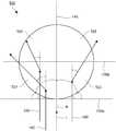
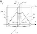
- FIG. 1It is sectional drawing which shows the cross section of the imaging unit which concerns on Embodiment 1 of this invention.
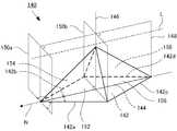
- the imaging unit 100includes an imaging device 110 that captures an imaging target and a housing 120.
- the housing 120has a box shape having a step in the height direction.
- the housing 120includes an upper stage portion 122 that houses the imaging device 110 and a lower stage portion 126 that houses a circuit board (not shown).
- the imaging unit 100images an imaging target (not shown) in a predetermined area in the traveling direction M of the vehicle 10. As shown in FIG. 2, the imaging unit 100 is attached to the windshield 12 of the vehicle 10 by bonding the upper surface 124 of the upper portion 122 of the housing 120 to the windshield 12 of the vehicle 10. In the imaging unit 100, the lower portion 126 of the housing 120 is directed in the traveling direction M of the vehicle 10. In this case, the upper surface 132 of the lower stage portion 126 of the housing 120 faces the windshield 12 of the vehicle 10.
- the imaging device 110includes an imaging lens 112 having an optical axis L and an imaging element 114.
- the imaging unit 100is attached to the windshield 12 of the vehicle 10, the imaging direction N of the imaging device 110, the optical axis L of the imaging lens 112, and the traveling direction M of the vehicle 10 match.
- Light from the imaging target that has passed through the opening 130 of the housing 120is incident on the imaging lens 112.
- An image to be imagedis formed on the image sensor 114.
- the image sensor 114is a CCD (Charge Coupled Device), CMOS (Complementary Metal Oxide Semiconductor) image sensor, or the like.
- the imaging device 110is housed in the upper portion 122 of the housing 120 with the imaging lens 112 facing the opening 130 of the housing 120. Further, the imaging device 110 uses the optical axis L of the imaging lens 112 as the upper surface of the upper portion 122 in order to make the traveling direction M of the vehicle 10 coincide with the imaging direction N of the imaging device 110 and the optical axis L of the imaging lens 112. It is housed in the housing 120 in a state tilted in the direction of 124.
- the casing 120is made of a metal such as aluminum die casting or magnesium die casting. Moreover, the housing
- the step side surface 128 of the housing 120is inclined toward the imaging direction N of the imaging device 110 as shown in FIG.
- An opening 130is provided in the center of the step side surface 128.
- the opening 130 of the housing 120allows light that enters the imaging lens 112 of the imaging device 110 from the imaging target to pass therethrough.
- a translucent plate(not shown) having translucency is provided in the opening 130 of the housing 120.
- a scattering portion 136is provided on the upper surface 132 of the lower portion 126 of the housing 120.
- the opening 130 of the housing 120is provided on the step side surface 128 of the housing 120.
- the imaging device 110is housed in the housing 120 with the imaging lens 112 facing the opening 130 of the housing 120. Therefore, the upper surface 132 of the lower stage portion 126 is a surface located on the optical axis L side of the imaging lens 112 in a portion extending from the opening 130 in the imaging direction N of the imaging device 110.
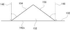
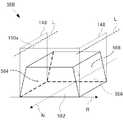
- the scattering portion 136is composed of a plurality of regular quadrangular pyramids 140 arranged on the upper surface 132 of the lower stage portion 126.
- each of the regular quadrangular pyramids 140has a square bottom surface 142.
- Each of the regular quadrangular pyramids 140is arranged such that the diagonal line 144 of the bottom surface 142 is parallel to the imaging direction N of the imaging device 110 (the optical axis L of the imaging lens 112) when the top surface 132 of the lower portion 126 is viewed in plan.
- the axis perpendicular to the upper surface 132 of the lower stage portion 126is the vertical axis 146
- the surface including the optical axis L of the imaging lens 112 and perpendicular to the upper surface 132 of the lower stage portion 126is the first vertical surface 148
- the upper surface of the lower stage portion 126is defined as second vertical surfaces 150a and 150b.
- the second vertical surface 150 ais located at a corner of the bottom surface 142.
- the second vertical surface 150 bis at a position that crosses the regular quadrangular pyramid 140.
- the first vertical surface 148includes the optical axis L of the imaging lens 112, the first vertical surface 148 is perpendicular to the opening 130 of the housing 120.
- the surface 152 including the side 142 a of the bottom surface 142 and the surface 154 including the side 142 b of the bottom surface 142 of the regular quadrangular pyramid 140are obtained when the top surface 132 of the lower portion 126 is viewed in plan view. It is located on the imaging direction N side of the imaging device 110 with respect to the second vertical plane 150b that crosses the pyramid 140. Therefore, the surface 152 and the surface 154 of the regular quadrangular pyramid 140 are surfaces located on the imaging direction N side of the imaging device 110. Note that the second vertical surface 150 a is located at a corner on the imaging direction N side of the imaging device 110.
- the surfaces 152 and 154 of the regular quadrangular pyramid 140are arranged so that the diagonal 144 of the bottom surface 142 of the regular quadrangular pyramid 140 is parallel to the imaging direction N of the imaging device 110 when the upper surface 132 of the lower portion 126 is viewed in plan view. It is inclined with respect to the first vertical surface 148 and the second vertical surface 150a. Further, the surface 152 and the surface 154 of the regular quadrangular pyramid 140 are inclined in opposite directions with respect to the first vertical surface 148.
- each of the surface 152 and the surface 154 of the regular quadrangular pyramid 140is inclined in a direction in which the upper ends thereof approach each other with respect to a surface (not shown) that includes the respective sides 142a and 142b and is perpendicular to the upper surface 132 of the lower step portion 126. is doing.
- the surface 156 including the side 142c of the bottom surface 142 and the surface 158 including the side 142d of the bottom surface 142 of the regular quadrangular pyramid 140are the housing 120 with respect to the second vertical surface 150b when the top surface 132 of the lower portion 126 is viewed in plan. Is located on the opening 130 side. Therefore, the surface 156 and the surface 158 of the regular quadrangular pyramid 140 are surfaces located on the opening 130 side of the housing 120.
- each of the regular quadrangular pyramids 140is arranged in a direction R perpendicular to the imaging direction N of the imaging device 110 with the corners of the bottom surfaces 142 in contact with each other. Further, the arrangement of the regular quadrangular pyramids 140 in the direction R is shifted in the imaging direction N of the imaging apparatus 110 by being shifted by half of the regular quadrangular pyramids 140 in the imaging direction N and the direction R of the imaging apparatus 110. In the arrangement in the adjacent direction R, the sides 142a and 142d and the sides 142b and 142c on the bottom surface 142 are in contact with each other.
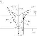
- incident light 160that is inclined from the vertical axis 146 toward the imaging direction N of the imaging device 110 by the angle ⁇ (0 ° ⁇ ⁇ 90 °) and parallel to the first vertical plane 148 enters the scattering unit 136.
- the incident light 160also enters the regular quadrangular pyramid 140.
- the incident light 160 incident on the regular quadrangular pyramid 140the incident light 160 incident on the surface 152 of the regular quadrangular pyramid 140 is inclined with respect to the first vertical surface 148 and the second vertical surface 150a. Therefore, as shown in FIG. 7, the light is reflected in a direction inclined with respect to the first vertical surface 148.
- the incident light 160 incident on the surface 154 of the regular quadrangular pyramid 140is also reflected in a direction inclined with respect to the first vertical surface 148, similarly to the incident light 160 incident on the surface 152.
- the surface 152 and the surface 154 of the regular quadrangular pyramid 140are inclined in opposite directions with respect to the first vertical surface 148. Therefore, the incident light 160 incident on the surface 152 of the regular quadrangular pyramid 140 and the incident light 160 incident on the surface 154 of the regular quadrangular pyramid 140 are different from each other when the upper surface 132 of the lower portion 126 is viewed in plan. Reflected in a direction inclined with respect to 148.
- the upper surface 132 of the lower part 126 of the housing 120faces the windshield 12 of the vehicle 10. Therefore, the scattering light 136 provided on the upper surface 132 of the lower stage portion 126 receives the largest amount of parallel light, that is, incident light 160, from obliquely above the upper surface 132 of the lower stage portion 126 that has passed through the windshield 12.
- the imaging unit 100can reduce the light that is reflected by the upper surface 132 of the lower portion 126 and is incident on the opening 130 of the housing 120 perpendicular to the first vertical surface 148.
- the imaging unit 100reduces the light that is reflected by the upper surface 132 of the lower portion 126 and enters the opening 130. Thereby, the imaging unit 100 can reduce the light reflected by the upper surface 132 of the lower part 126 and entering the imaging lens 112. Similarly to the surfaces 152 and 154 of the regular quadrangular pyramid 140, the surfaces 156 and 158 of the regular quadrangular pyramid 140 can also reflect the incident light 160 in different directions inclined with respect to the first vertical surface 148. . Therefore, the imaging unit 100 can further reduce the light reflected by the upper surface 132 of the lower portion 126 and entering the imaging lens 112.
- the imaging unit 100 in the present embodimentwill be described with reference to FIGS.
- only one regular quadrangular pyramid 140is shown in FIGS.
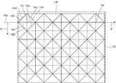
- each of the regular quadrangular pyramids 140is arranged in parallel with a direction R in which the side 142 a of the bottom surface 142 is perpendicular to the imaging direction N of the imaging device 110 when the top surface 132 of the lower portion 126 is viewed in plan. Is done. Further, as shown in FIG. 9, the regular quadrangular pyramids 140 are arranged in a matrix with the arrangement in the direction R being shifted by a half pitch for each arrangement. Other configurations are the same as those of the first embodiment.
- the surface 154 and the surface 156 of the regular quadrangular pyramid 140are perpendicular to the second vertical surface 150a. Also, as shown in FIG. 10, the surface 154 and the surface 156 of the regular quadrangular pyramid 140 are in relation to the first vertical surface 148 when the upper surface 132 of the lower portion 126 is viewed from the imaging direction N of the imaging device 110. It inclines in the direction in which the upper ends of each other approach.
- the incident light 160 incident on the surface 154is the first vertical surface when the surface 154 is a cross-sectional view of the upper surface 132 of the lower portion 126. Since it is inclined with respect to 148, it is reflected in a direction inclined with respect to the first vertical surface 148 as shown in FIG.
- the incident light 160 incident on the surface 156is reflected in a direction inclined with respect to the first vertical surface 148, similarly to the incident light 160 incident on the surface 154.
- the surface 154 and the surface 156are inclined in a direction in which the upper ends of the first vertical surface 148 approach each other, and thus the incident light 160 incident on the surface 154
- the incident light 160 incident on the surface 156is reflected in different directions inclined with respect to the first vertical surface 148 when the upper surface 132 of the lower portion 126 is viewed in plan.
- the regular quadrangular pyramid 140reflects the incident light 160 in different directions inclined with respect to the first vertical plane 148 when the upper surface 132 is viewed in plan, as in the first embodiment. . Therefore, the imaging unit 100 according to the present embodiment can also reduce the light reflected by the upper surface 132 and incident on the opening 130, that is, the light reflected by the upper surface 132 and incident on the imaging lens 112.
- the width T1 of the upper surface 132 of the lower portion 126is 50 mm
- the depth T2is 20 mm
- the height T3 of the step side surface 128is 15 mm.
- the angle ⁇ of the step side surface 128 with respect to the upper surface 132is 60 °
- the width T4 of the opening 130 provided in the center of the step side surface 128is 15 mm
- the length T5 in the height directionis 12 mm.
- the regular quadrangular pyramids 140are arranged in the same matrix form as in FIG. In the regular quadrangular pyramid 140, the sides 142a, 142b, 142c, 142d of the bottom surface 142 have a length of 2 mm and a height of 1 mm.
- the incident light 160 inclined at an angle ⁇75 ° in the imaging direction N of the imaging device 110 from the vertical axis 146 perpendicular to the upper surface 132 was irradiated to the casing 120 in the vicinity of the center of the upper surface 132.
- the light source that emits the incident light 160is a circular light source having a diameter of 2 mm, which is a size that prevents the incident light 160 from being blocked by the frame that supports the windshield 12. Furthermore, the reflectance of the regular quadrangular pyramid 140 was 100%.
- the ratio of the amount of incident light 160 incident on the opening 130 to the amount of incident light 160 incident on the upper surface 132was simulated by commercially available ray tracing simulation software.
- a simulationwas performed in the same manner with respect to a casing that does not include the scattering portion 136 on the upper surface 132.
- the casing of the comparative exampleis the same as the casing 120 except that the scattering portion 136 (regular quadrangular pyramid 140) is not provided.
- the incident light 160 incident on the casing of the comparative exampleis the same as the incident light 160 incident on the casing 120.
- the reflectance of the upper surface 132was 100%.
- the optical simulationshows that the light reflected from the upper surface 132 and incident on the opening 130 can be reduced by providing the upper surface 132 with the scattering portion 136 composed of the regular pyramid 140.
- the imaging unit 100 in the present embodimentcan reduce the light reflected by the upper surface 132 and incident on the imaging lens 112.
- the scattering unit 136includes a plurality of regular quadrangular pyramids 140.
- the structure that configures the scattering unit 136is not limited thereto.
- the scattering portion 136includes a plurality of triangular pyramids 210.
- Other configurationsare the same as those of the first embodiment.
- only one triangular pyramid 210is shown in FIG.
- Each of the triangular pyramids 210has a triangular bottom surface (not shown). As shown in FIGS. 13 and 14, each of the triangular pyramids 210 has a vertical line 216 extending from the bottom surface corner 214 to the bottom surface side 212 a facing the corner 214 when the top surface 132 of the lower stage portion 126 is viewed in plan view. 110 parallel to the imaging direction N. A corner 214 on the bottom surface of the triangular pyramid 210 is located on the imaging direction N side of the imaging device 110, and a side 212 a on the bottom surface of the triangular pyramid 210 is located on the opening 130 side of the housing 120.
- the surface 218 of the triangular pyramid 210 including the bottom side 212 b of the triangular pyramid 210is a second vertical crossing the triangular pyramid 210 when the upper surface 132 of the lower portion 126 is viewed in plan. Since the surface 150b is located on the imaging direction N side of the imaging device 110, the surface is located on the imaging direction N side of the imaging device 110. Further, the surface 220 of the triangular pyramid 210 including the side 212 c of the bottom surface of the triangular pyramid 210 is a surface located on the imaging direction N side of the imaging device 110, similarly to the surface 218.
- the side 212b and the side 212c on the bottom surface of the triangular pyramid 210sandwich the corner 214 on the bottom surface of the triangular pyramid 210.
- the surface 222 including the side 212a of the bottom surface of the triangular pyramid 210is located on the opening 130 side of the housing 120 with respect to the second vertical surface 150b when the upper surface 132 of the lower portion 126 is viewed in plan view. It becomes a surface located on the opening 130 side of the body 120.
- the surface 218 and the surface 220 of the triangular pyramid 210are arranged such that the perpendicular 216 of the triangular pyramid 210 and the imaging direction N of the imaging device 110 are arranged in parallel, so that the first vertical surface 148 and the second vertical surface 150a It is inclined with respect to. Further, the surface 218 and the surface 220 are inclined in opposite directions with respect to the first vertical surface 148. Each of the surface 218 and the surface 220 is inclined in a direction in which the upper ends thereof approach each other with respect to a surface (not shown) that includes the respective sides 212b and 212c and is perpendicular to the upper surface 132 of the lower portion 126.
- Each of the triangular pyramids 210is arranged in a matrix in the imaging direction N and the direction R of the imaging device 110 as shown in FIG.
- the side 212a of the bottom surface and the corner 214 of the bottom surfaceare in contact with each other.
- the ends of the side 212a of the bottom surfaceare in contact with each other.
- the incident light 160 incident on the surface 218has the surface 218 inclined with respect to the first vertical surface 148 and the second vertical surface 150a. As shown, when the top surface 132 is viewed in plan, the light is reflected in a direction inclined with respect to the first vertical surface 148. Similarly to the incident light 160 incident on the surface 218, the incident light 160 incident on the surface 220 is also reflected in a direction inclined with respect to the first vertical surface 148 when the upper surface 132 is viewed in plan.
- the incident light 160 incident on the surface 218 and the incident light 160 incident on the surface 220are viewed in plan view on the upper surface 132. In this case, the light beams are reflected in directions different from each other and inclined with respect to the first vertical surface 148.
- the triangular pyramid 210reflects the incident light 160 in different directions inclined with respect to the first vertical plane 148 when the upper surface 132 is viewed in plan. Therefore, the imaging unit 100 can reduce the light reflected by the upper surface 132 and incident on the opening 130 as in the first embodiment. Thereby, the imaging unit 100 can reduce the light reflected by the upper surface 132 and incident on the imaging lens 112.
- the scattering unit 136is formed of a pyramid, but the structure constituting the scattering unit 136 is not limited to this.
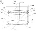
- the scattering portion 136includes a plurality of hemispheres 510. Other configurations are the same as those of the first embodiment. For ease of understanding, only one hemisphere 510 is shown in FIGS.
- the hemisphere 510is arranged in a matrix with the arrangement in the direction R being shifted by a half pitch for each arrangement.
- the hemisphere 510is divided into four by a first vertical surface 148 and a second vertical surface 150b that crosses the hemisphere 510, as shown in FIG.
- the surface of the hemisphere 510is composed of four faces 512, 514, 516, 518.
- the second vertical surface 150 ais in contact with the circumference of the bottom surface (not shown) of the hemisphere 510 on the imaging direction N side of the imaging device 110.
- the surface 512 and the surface 514are located on the imaging direction N side of the imaging device 110 with respect to the second vertical surface 150b crossing the hemisphere 510 when the upper surface 132 of the lower stage portion 126 is viewed in plan. Accordingly, the surface 512 and the surface 514 are surfaces located on the imaging direction N side of the imaging device 110. Further, since the bottom surface of the hemisphere 510 is circular, the surfaces 512 and 514 are inclined with respect to the first vertical surface 148 and the second vertical surface 150a, and are opposite to each other with respect to the first vertical surface 148. Inclined in the direction.
- each of the surface 512 and the surface 514is inclined in a direction in which the upper ends of the surfaces 512 and 514 approach each other with respect to a surface (not shown) perpendicular to the upper surface 132 including the arc located on the upper surface 132.
- the incident light 160 incident on the surface 512has the surface 512 inclined with respect to the first vertical surface 148 and the second vertical surface 150a. As shown, the light is reflected in a direction inclined with respect to the first vertical surface 148. Similarly to the incident light 160 incident on the surface 512, the incident light 160 incident on the surface 514 is reflected in a direction inclined with respect to the first vertical surface 148.
- the incident light 160 incident on the surface 512 and the incident light 160 incident on the surface 514are viewed in plan view on the upper surface 132. In this case, the light beams are reflected in directions different from each other and inclined with respect to the first vertical surface 148.
- the imaging unit 100can also reduce the light that is reflected by the upper surface 132 and enters the opening 130, as in the first embodiment. Thereby, the imaging unit 100 in the present embodiment can reduce the light reflected by the upper surface 132 and incident on the imaging lens 112.
- each of the surface 512 and the surface 514is a curved surface, the incident light 160 incident on different positions is reflected at different angles with respect to the first vertical surface 148 as shown in FIG.
- the imaging unit 100 in the present embodimentcan further reduce the light reflected by the upper surface 132 and entering the opening 130.
- the surfaces 516 and 518 located on the opening 130 side of the housing 120can also reflect the incident light 160 in directions inclined with respect to the first vertical surfaces 148 different from each other.
- the surfaces 516 and 518can reflect the incident light 160 incident at different positions with respect to the first vertical surface 148 at different angles. Therefore, the imaging unit 100 in the present embodiment can further reduce the light reflected by the upper surface 132 and entering the opening 130.
- the scattering unit 136is formed of a pyramid, but the structure constituting the scattering unit 136 is not limited to this.
- the scattering portion 136is composed of a plurality of cones 520. Other configurations are the same as those of the first embodiment. For ease of understanding, only one cone 520 is shown in FIGS.
- the cones 520are arranged in a matrix with the arrangement in the direction R being shifted by a half pitch for each arrangement.
- the cone 520is divided into four parts by a first vertical surface 148 and a second vertical surface 150b crossing the cone 520, as shown in FIG.
- the surface of the cone 520is composed of four faces 522, 524, 526, 528.
- the second vertical surface 150ais in contact with the circumference of the bottom surface (not shown) of the cone 520 on the imaging direction N side of the imaging device 110.
- the imaging device 110Since the surface 522 and the surface 524 are located on the imaging direction N side of the imaging device 110 with respect to the second vertical surface 150b crossing the cone 520 when the upper surface 132 of the lower portion 126 is viewed in plan, the imaging device 110 The surface is located on the imaging direction N side. Further, since the bottom surface of the cone 520 is circular, the surface 522 and the surface 524 are inclined with respect to the first vertical surface 148 and the second vertical surface 150a as in the fourth embodiment, and are first to each other. The vertical plane 148 is inclined in the opposite direction.
- each of the surface 522 and the surface 524is inclined in a direction in which the upper ends of the surfaces 522 and 524 approach each other with respect to a surface (not shown) perpendicular to the upper surface 132 including the arc located on the upper surface 132 of the lower step portion 126. ing.
- the imaging unit 100 in the present embodimentcan also reduce the light reflected by the upper surface 132 and entering the opening 130 of the housing 120. Thereby, the imaging unit 100 in the present embodiment can reduce the light reflected by the upper surface 132 and incident on the imaging lens 112.
- the imaging unit 100 in the present embodimentcan further reduce the light reflected by the upper surface 132 and entering the opening 130 of the housing 120.
- the surface 526 and the surface 528 located on the opening 130 side of the housing 120can also reflect the incident light 160 in a direction inclined with respect to the first vertical surfaces 148 different from each other, similarly to the surfaces 522 and 524. .
- the surfaces 526 and 528can reflect the incident light 160 incident at different positions with respect to the first vertical surface 148 at different angles. Therefore, the imaging unit 100 in the present embodiment can further reduce the light reflected by the upper surface 132 and entering the opening 130.
- the surfaces 152, 154, 218, 220, 512, 514, 522, and 524 located on the imaging direction N side of the imaging device 110are perpendicular to the upper surface 132.
- the surfaceis inclined with respect to the smooth surface, the surface located on the imaging direction N side of the imaging device 110 may be perpendicular to the upper surface 132.
- the scattering unit 136includes a plurality of cylinders 530. Other configurations are the same as those of the first embodiment.
- the cylinders 530are arranged in a matrix similar to the fourth embodiment, with the arrangement in the direction R being shifted by a half pitch for each arrangement.
- the cylinder 530is divided into four by a first vertical surface 148 and a second vertical surface 150 b that crosses the cylinder 530.
- the surface of the cylinder 530includes eight surfaces 531, 532, 533, 534, 535, 536, 537 and 538.
- the surface 531 and the surface 532are located on the imaging direction N side of the imaging device 110.
- the surfaces 531 and 532are surfaces perpendicular to the upper surface 132 of the lower stage portion 126. Further, the surface 533 and the surface 534 are located on the opening 130 side of the housing 120.
- the surface 533 and the surface 534are surfaces that are perpendicular to the upper surface 132 of the lower portion 126. Note that the surfaces 535 and 536 located on the imaging direction N side of the imaging device 110 and the surfaces 537 and 538 located on the opening 130 side of the housing 120 are surfaces parallel to the upper surface 132 of the lower portion 126.
- the surface 531 and the surface 532are inclined with respect to the first vertical surface 148 and the second vertical surface 150a as in the fourth embodiment. Further, the surface 531 and the surface 532 are inclined in opposite directions with respect to the first vertical surface 148. Therefore, when the incident light 160 enters the scattering portion 136, the cylinder 530 is inclined with respect to the first vertical planes 148 different from each other when the upper surface 132 is viewed in plan, as shown in FIG. Reflect in the direction. Further, since each of the surface 531 and the surface 532 is a curved surface, the incident light 160 incident at different positions is reflected at different angles with respect to the first vertical surface 148.
- the imaging unit 100also reduces the light reflected by the upper surface 132 and incident on the opening 130 of the housing 120 and reflected by the upper surface 132 and applied to the imaging lens 112 as in the first embodiment. Incident light can be reduced.
- the scattering unit 136is formed of a pyramid, but the scattering unit 136 may be formed of a truncated pyramid.
- the scattering unit 136includes a plurality of regular quadrangular frustums 540. Other configurations are the same as those of the first embodiment.
- the regular quadrangular frustum 540has a square bottom surface 542 and a top surface 543.
- the regular quadrangular frustum 540has the side 542a of the bottom surface 542 arranged in parallel with the direction R when the top surface 132 of the lower stage portion 126 is viewed in plan.
- the regular quadrangular frustum 540is arranged in a matrix with the arrangement in the direction R shifted by a half pitch for each arrangement.
- the surface 545 including the side 542b of the bottom surface 542 and the surface 546 including the bottom surface 542care perpendicular to the second vertical surface 150a. Further, as illustrated in FIG.
- the surface 545 and the surface 546are inclined in a direction in which the upper ends of the surface 545 and the surface 546 approach each other with respect to the first vertical surface 148 when the upper surface 132 is viewed in cross section from the imaging direction N of the imaging device 110 is doing.
- the upper surface 543 of the regular quadrangular frustum 540is continuous with the surface 545 and the surface 546.
- a surface 544 including the side 542 a of the bottom surface 542 and a surface 547 including the side 542 d of the bottom surfaceare perpendicular to the first vertical surface 148.
- the imaging unit 100 in the present embodimentcan also reduce the light reflected by the upper surface 132 and entering the opening 130 of the housing 120. Thereby, the imaging unit 100 in the present embodiment can reduce the light reflected by the upper surface 132 and incident on the imaging lens 112.
- the scattering portion 136is provided on the upper surface 132 of the lower portion 126 of the casing 120, but the surface on which the scattering portion 136 is provided is not limited to this.
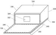
- the imaging unit 300includes an imaging device 110, a housing 320 that houses the imaging device 110, and a mounting portion 330. Note that the configuration of the imaging device 110 is the same as that of the first embodiment.
- the housing 320is fixed to the windshield 12 of the vehicle 10 via the attachment portion 330.
- the imaging direction N of the imaging device 110, the optical axis L of the imaging lens 112, and the traveling direction M of the vehicle 10coincide.
- the fixing of the housing 320will be described later.
- the housing 320has a box shape.
- the housing 320has an opening 324 on the side surface 322.
- the opening 324 of the housing 320allows light incident on the imaging lens 112 of the imaging device 110 from the imaging target to pass, like the opening 130 of the housing 120 in the first embodiment.
- the housing 320is made of a metal such as aluminum die casting or magnesium die casting.
- the housing 320is black.
- the imaging device 110is housed in the housing 320 with the optical axis L of the imaging lens 112 parallel to the housing 320 and the optical axis L of the imaging lens 112 facing the opening 324.
- the attachment portion 330includes a bottom plate 332 on which the housing 320 is provided, side plates 334 and 336, and an upper plate 338.
- the attachment portion 330is made of a metal such as aluminum die casting or magnesium die casting, for example.
- the attachment part 330is black.
- the side plate 334 and the side plate 336are respectively connected to the opposing end portions of the bottom plate 332.
- the upper plate 338connects the side plate 334 and the side plate 336 at the end opposite to the end connected to the bottom plate 332.
- the upper plate 338is inclined in accordance with the inclination of the windshield 12 of the vehicle 10.
- the bottom plate 332includes an extending portion 342 extending from an opening 340 formed by the bottom plate 332, the side plates 334 and 336, and the upper plate 338.
- the housing 320is fixed to the bottom plate 332 in a state where the side surface 322 having the opening 324 is fitted into the opening 340 of the attachment portion 330.
- the housing 320is fixed to the bottom plate 332 of the attachment portion 330 by, for example, screwing.
- the extension part 342 of the attachment part 330extends from the opening part 324 of the case 320 because the side surface 322 of the case 320 is fitted in the opening part 340 of the attachment part 330.
- the imaging device 110since the imaging device 110 is housed in the housing 320 with the optical axis L of the imaging lens 112 facing the opening 324 of the housing 320, the extending portion 342 of the attachment portion 330 is captured by the imaging device 110. It extends in the direction N.
- the scattering portion 136is provided on the first extending surface 344 of the extending portion 342.
- the first extending surface 344is a surface on the optical axis L side of the imaging lens 112 of the extending portion 342.
- the scattering unit 136 provided on the first extension surface 344is configured by a plurality of regular quadrangular pyramids 140, for example, as in the first embodiment.
- the fixing of the housing 320 to the windshield 12 of the vehicle 10will be described.
- the casing 320is fixed to the windshield 12 by bonding the upper plate 338 of the attachment portion 330 to which the casing 320 is fixed to the windshield 12 of the vehicle 10.
- the extension part 342 of the attachment part 330faces the traveling direction M of the vehicle 10, and the traveling direction M of the vehicle 10, the imaging direction N of the imaging device 110, and the optical axis L of the imaging lens 112 are matched.
- the casing 320is placed in a state where the casing 320 is horizontal to the road surface. It can be fixed to the windshield 12 of the vehicle 10. And since it is not necessary to incline the optical axis L of the imaging lens 112 of the imaging device 110 with respect to the housing 320, the imaging device 110 can be easily arranged in the housing 320. Further, a scattering portion 136 similar to that in Embodiment 1 is provided on the first extending surface 344 located on the optical axis L side of the imaging lens 112.
- the imaging unit 300can also reduce the light that is reflected by the first extending surface 344 of the attachment portion 330 and enters the opening 324 of the housing 320. Thereby, the imaging unit 300 can reduce the light reflected by the first extending surface 344 and incident on the imaging lens 112.
- the imaging units 100 and 300may be attached not only to the windshield 12 of the vehicle 10 but also to a rear glass, a side glass, a ceiling, and the like.
- the vehicle 10is a vehicle for transporting passengers / cargo such as automobiles and trains.
- the imaging units 100 and 300may be attached to a vehicle other than the vehicle 10 such as an aircraft or a ship. Attachment of the imaging units 100 and 300 is not limited to adhesion.
- the imaging units 100 and 300may be attached to the windshield 12 of the vehicle 10 via a suction cup.
- the imaging device 110only needs to be partially stored in the casings 120 and 320.
- the imaging lens 112 of the imaging device 110may be exposed to the step side surface 128 of the housing 120 through the opening 130.
- a lens barrel including the imaging lens 112 of the imaging device 110may protrude from the opening 130 of the housing 120.
- the imaging lens 112 of the imaging device 110is not limited to one, and may be a plurality of lenses.
- the casings 120 and 320are not limited to a box shape.
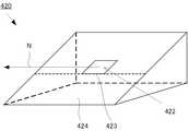
- the housing that houses the imaging device 110may be a housing 420 having a triangular cross section.
- the scattering portion 136is provided on a surface 424 that extends from the lower end 423 of the opening 422 of the housing 420 in the imaging direction N of the imaging device 110.
- the scattering portion 136may be provided on a surface 128 a extending from the lower end 134 of the opening 130 in the step side surface 128 of the housing 120 to the upper surface 132 of the lower step portion 126.
- the casings 120, 320, 420, and the attachment portion 330may be formed of a resin such as polycarbonate or ABS (acrylonitrile-butadiene-styrene).
- the scattering unit 136is not limited to the casings 120 and 420 and the attachment unit 330, and may be provided in a lens hood or the like.
- the structure constituting the scattering unit 136is not limited to the regular quadrangular pyramid 140, the triangular pyramid 210, the cone 520, and the like.
- the structure constituting the scattering unit 136may be a truncated cone 550, for example.
- the truncated cone 550has a surface 552 and a surface 554. As illustrated in FIG. 30, the surface 552 and the surface 554 are located on the imaging direction N side of the imaging device 110 and are inclined in opposite directions with respect to the first vertical surface 148.
- the surface 552 and the surface 554are inclined in a direction in which the upper ends approach each other with respect to a surface (not shown) perpendicular to the upper surface 132 including the arc located on the upper surface 132 of the lower stage portion 126. Accordingly, similarly to the cone 520, the truncated cone 550 can also reflect the incident light 160 in a direction inclined with respect to the first vertical surfaces 148 different from each other when the upper surface 132 is viewed in plan. Furthermore, since the surface 552 and the surface 554 are curved surfaces, incident light 160 incident on different positions can be reflected at different angles with respect to the first vertical surface 148.
- the imaging unit 100 in which the scattering unit 136 includes the truncated cone 550can reduce the light reflected by the upper surface 132 and entering the opening 130 of the housing 120. Thereby, the imaging unit 100 can reduce the light reflected by the upper surface 132 and incident on the imaging lens 112.
- the surface 556 and the surface 558 positioned on the opening 130 side of the housing 120are inclined with respect to the first vertical surface 148 that is different from the first vertical surface 148 that is different from the surface 552 and the surface 554. Can be reflected in any direction. Similar to the surfaces 552 and 554, the surfaces 556 and 558 can reflect the incident light 160 incident at different positions with respect to the first vertical surface 148 at different angles.
- the imaging unit 100can further reduce the light reflected by the upper surface 132 and entering the opening 130 of the housing 120.
- the truncated cone 550is arranged on the upper surface 132 in the same matrix as in FIG. 18, 3.2% of the incident light 160 is an opening. The result that it injects into 130 was obtained.
- the bottom surface radius of the truncated cone 550is 1 mm
- the heightis 0.45 mm
- the top surface radiusis 0.437 mm.
- the structures constituting the scattering unit 136are arranged as a quadrangular pyramid, an n-pyramid (n is an integer of 5 or more), and a predetermined interval.
- n-pyramidan integer of 5 or more
- a predetermined intervala triangular prism or the like may be used.
- the structure constituting the scattering unit 136may be, for example, a quadrangular frustum 560 in which one opposing side surface is parallel.
- the quadrangular frustum 560has one side surface 562 and a side surface 568 that are opposed to each other.
- the side surfaces 562 and 568are arranged in parallel to the second vertical surface 150a.
- the other opposing side surface 564 and side surface 566are perpendicular to the second vertical surface 150a and are inclined in a direction in which their upper ends approach each other with respect to the first vertical surface 148.
- the side surface 564 and the side surface 566may be curved surfaces.
- the arrangement of the structures constituting the scattering portion 136may be irregular.
Landscapes
- Physics & Mathematics (AREA)
- General Physics & Mathematics (AREA)
- Engineering & Computer Science (AREA)
- Multimedia (AREA)
- Signal Processing (AREA)
- Mechanical Engineering (AREA)
- Studio Devices (AREA)
Abstract
Description
Translated fromJapanese本発明は、撮像ユニット並びにこれを備える車両用のフロントガラス及び車両に関する。The present invention relates to an imaging unit, a windshield for a vehicle including the imaging unit, and a vehicle.
車載カメラを用いた運転支援システムの開発が進められている。例えば、特許文献1に記載の車線認識装置では、車載カメラによって撮像された画像から車線の位置を検出する。
このような車載カメラは、カメラレンズが露出した筐体の上面が、車両のフロントガラスに対向するように、車両内に取り付けられる。特許文献2に記載の車載カメラでは、筐体の一部が、車両内の下方からフロントガラスに入射する光を遮ることによって、フロントガラスにおける映り込みを防いでいる。Development of driving support systems using in-vehicle cameras is in progress. For example, in the lane recognition device described in Patent Document 1, the position of a lane is detected from an image captured by an in-vehicle camera.
Such an in-vehicle camera is mounted in the vehicle such that the upper surface of the casing from which the camera lens is exposed faces the windshield of the vehicle. In the vehicle-mounted camera described in Patent Document 2, a part of the housing prevents reflection on the windshield by blocking light incident on the windshield from below in the vehicle.
特許文献2に記載の車載カメラでは、フロントガラスにおける映り込みを防ぐ筐体の一部が、カメラレンズの位置よりも撮像方向に延びているので、カメラレンズから撮像方向に延びる筐体の面(すなわち、凹部内上面)が、車両外からフロントガラスを透過した光を反射する。この反射された光がカメラレンズに入射するので、撮像された画像にゴースト、フレアなどが生じる場合がある。In the in-vehicle camera described in Patent Document 2, a part of the casing that prevents reflection on the windshield extends in the imaging direction from the position of the camera lens. That is, the upper surface in the concave portion reflects light transmitted through the windshield from the outside of the vehicle. Since the reflected light is incident on the camera lens, ghosts, flares, and the like may occur in the captured image.
本発明は、上記の事情に鑑みてなされたものであり、撮像レンズよりも撮像方向側に位置する面によって反射され撮像レンズに入射する光を減少させ、撮像された画像におけるゴースト、フレアの発生を抑制できる撮像ユニット並びにこれを備える車両用のフロントガラス及び車両を提供することを目的とする。The present invention has been made in view of the above circumstances, and reduces light incident on the imaging lens that is reflected by a surface located on the imaging direction side of the imaging lens, thereby generating ghost and flare in the captured image. An object of the present invention is to provide an imaging unit capable of suppressing the above, a windshield for a vehicle including the same, and a vehicle.
(1)上記目的を達成するため、本発明の第1の観点に係る撮像ユニットは、
撮像レンズを有する撮像装置と、
前記撮像装置の少なくとも一部を収納し、前記撮像装置の撮像対象から前記撮像レンズに入射する光を通過させる開口部を有する筐体と、
前記筐体の開口部から前記撮像装置の撮像方向に延びる延出部と、を備え、
前記延出部は前記撮像レンズの光軸側に位置する第1の延出面を有し、
前記第1の延出面には、入射した光を複数の構造体によって散乱する散乱部が設けられ、
前記構造体のそれぞれが、前記第1の延出面に垂直な軸に対して前記撮像装置の撮像方向に傾き前記第1の延出面に対して傾いた方向から入射した、前記撮像レンズの光軸を含み前記第1の延出面に垂直な第1の垂直面に平行な光を、前記第1の延出面を平面視した場合に、少なくとも2つの互いに異なる、前記第1の垂直面に対して傾いた方向に反射する表面構造を有する。(1) In order to achieve the above object, an imaging unit according to the first aspect of the present invention includes:
An imaging device having an imaging lens;
A housing having at least a part of the imaging device and having an opening through which light incident on the imaging lens from an imaging target of the imaging device passes
An extending portion extending from the opening of the housing in the imaging direction of the imaging device,
The extending portion has a first extending surface located on the optical axis side of the imaging lens,
The first extending surface is provided with a scattering portion that scatters incident light by a plurality of structures,
The optical axis of the imaging lens in which each of the structures is incident in a direction inclined with respect to the imaging direction of the imaging device with respect to an axis perpendicular to the first extending surface and with respect to the first extending surface. Light parallel to the first vertical surface perpendicular to the first extension surface, and when the first extension surface is viewed in plan, at least two different first vertical surfaces from each other It has a surface structure that reflects in an inclined direction.
(2)上記(1)において、前記第1の延出面に垂直で前記第1の垂直面に垂直な第2の垂直面を仮定し、前記第1の延出面を平面視した場合、前記構造体のそれぞれは、少なくとも、前記撮像装置の撮像方向側に位置する第1の面と第2の面と、前記開口部側に位置する面とを有し、前記第1の面と前記第2の面は、前記第1の垂直面と前記第2の垂直面とに対して傾斜し、互いに前記第1の垂直面に対して逆方向に傾斜してもよい。(2) In the above (1), when the second extending surface perpendicular to the first extending surface and perpendicular to the first extending surface is assumed, and the first extending surface is viewed in plan, the structure Each of the bodies has at least a first surface and a second surface located on the imaging direction side of the imaging device, and a surface located on the opening side, and the first surface and the second surface These surfaces may be inclined with respect to the first vertical surface and the second vertical surface, and may be inclined in opposite directions with respect to the first vertical surface.
(3)上記(2)において、前記第1の面と前記第2の面の少なくとも一方が、前記第1の延出面に垂直な面に対して互いの上端が近づく方向に傾斜してもよい。(3) In the above (2), at least one of the first surface and the second surface may be inclined in a direction in which the upper ends approach each other with respect to a surface perpendicular to the first extending surface. .
上記(1)~(3)のような構成により、撮像レンズよりも撮像方向側に位置する面によって反射され撮像レンズに入射する光を減少させ、撮像された画像におけるゴースト、フレアの発生を抑制できる。With the configuration as described in (1) to (3) above, the light that is reflected by the surface located on the imaging direction side of the imaging lens and incident on the imaging lens is reduced, and the occurrence of ghost and flare in the captured image is suppressed. it can.
(4)上記(2)、(3)において、前記第1の面と前記第2の面の少なくとも一方が曲面であってもよい。このような構成により、構造体が、第1の垂直面に平行な光を入射位置によって異なる角度で反射するので、撮像レンズよりも撮像方向側に位置する面によって反射され撮像レンズに入射する光を、さらに減少させることができる。(4) In the above (2) and (3), at least one of the first surface and the second surface may be a curved surface. With such a configuration, the structure reflects light parallel to the first vertical surface at different angles depending on the incident position, so that the light reflected by the surface located on the imaging direction side of the imaging lens and incident on the imaging lens. Can be further reduced.
(5)さらに、上記(2)~(4)において、前記第1の面と前記第2の面とが連続してもよい。このような構成により、構造体によって第1の垂直面に対して平行な方向に反射される光を減少させることができ、撮像レンズよりも撮像方向側に位置する面によって反射され撮像レンズに入射する光を、さらに減少させることができる。(5) Further, in the above (2) to (4), the first surface and the second surface may be continuous. With such a configuration, the light reflected by the structure in the direction parallel to the first vertical plane can be reduced, and the light reflected by the surface located on the imaging direction side from the imaging lens is incident on the imaging lens. Light to be further reduced.
(6)上記(2)において、前記複数の構造体が、角錐、角錐台、円錐、円錐台、半球又は円柱の少なくともいずれか1つであってもよい。(6) In the above (2), the plurality of structures may be at least one of a pyramid, a truncated pyramid, a cone, a truncated cone, a hemisphere, or a cylinder.
(7)上記(1)において、前記第1の延出面に垂直で前記第1の垂直面に垂直な第2の垂直面を仮定し、前記撮像装置の撮像方向から前記第1の延出面を断面視した場合、前記構造体のそれぞれは、少なくとも、前記第2の垂直面に垂直な第3の面と第4の面とを有し、前記第3の面と前記第4の面が前記第1の垂直面に対して互いの上端が近づく方向に傾斜してもよい。(7) In the above (1), assuming a second vertical surface perpendicular to the first extension surface and perpendicular to the first vertical surface, the first extension surface is defined from the imaging direction of the imaging device. When viewed in cross-section, each of the structures has at least a third surface and a fourth surface perpendicular to the second vertical surface, and the third surface and the fourth surface are You may incline in the direction which a mutual upper end approaches with respect to a 1st perpendicular surface.
(8)上記(7)において、前記構造体が、前記第3の面と前記第4の面とに連続する第5の面を有してもよい。(8) In the above (7), the structure may have a fifth surface continuous to the third surface and the fourth surface.
上記(7)、(8)のような構成により、撮像レンズよりも撮像方向側に位置する面によって反射され撮像レンズに入射する光を減少させ、撮像された画像におけるゴースト、フレアの発生を抑制できる。With the configuration as described in (7) and (8) above, the light reflected by the surface located on the imaging direction side from the imaging lens and incident on the imaging lens is reduced, and the occurrence of ghost and flare in the captured image is suppressed. it can.
(9)上記(7)、(8)において、前記第3の面と前記第4の面の少なくとも一方が曲面であってもよい。このような構成により、構造体が、第1の垂直面に平行な光を入射位置によって異なる角度で反射するので、撮像レンズよりも撮像方向側に位置する面によって反射され撮像レンズに入射する光を、さらに減少させることができる。(9) In the above (7) and (8), at least one of the third surface and the fourth surface may be a curved surface. With such a configuration, the structure reflects light parallel to the first vertical surface at different angles depending on the incident position, so that the light reflected by the surface located on the imaging direction side of the imaging lens and incident on the imaging lens. Can be further reduced.
(10)上記(7)において、前記複数の構造体が角錐又は角錐台の少なくとも一方であってもよい。(10) In the above (7), the plurality of structures may be a pyramid or at least one of a truncated pyramid.
(11)上記(1)~(10)において、前記第1の延出面を平面視した場合、前記構造体が前記撮像装置の撮像方向と前記撮像装置の撮像方向に垂直な方向とに配列されてもよい。
(12)上記(1)~(11)において、前記延出部は前記筐体の一部であってもよい。
(13)上記(1)~(11)において、前記筐体を車両内に固定する取り付け部を備え、前記延出部が前記取り付け部の一部であってもよい。(11) In the above (1) to (10), when the first extending surface is viewed in plan, the structures are arranged in an imaging direction of the imaging device and a direction perpendicular to the imaging direction of the imaging device. May be.
(12) In the above (1) to (11), the extending part may be a part of the casing.
(13) In the above (1) to (11), an attachment portion for fixing the casing in the vehicle may be provided, and the extension portion may be a part of the attachment portion.
(14)本発明の第2の観点に係る車両用のフロントガラスは、
上記撮像ユニットを備える。(14) The vehicle windshield according to the second aspect of the present invention provides:
The imaging unit is provided.
(15)本発明の第3の観点に係る車両は、
上記撮像ユニットを備える。(15) A vehicle according to a third aspect of the present invention is:
The imaging unit is provided.
本発明によれば、撮像レンズよりも撮像方向側に位置する面によって反射され撮像レンズに入射する光を減少させ、撮像された画像におけるゴースト、フレアの発生を抑制できる。According to the present invention, it is possible to reduce the light reflected by the surface located on the imaging direction side of the imaging lens and incident on the imaging lens, and to suppress the occurrence of ghost and flare in the captured image.
(実施の形態1)
図1~図7を参照して、本実施の形態における撮像ユニット100を説明する。(Embodiment 1)
The
撮像ユニット100は、図1に示すように、撮像対象を撮像する撮像装置110と筐体120とを備える。筐体120は高さ方向に段差を有する箱型形状である。筐体120は、撮像装置110を収納する上段部分122と回路基板(図示せず)などを収納する下段部分126とを備える。As shown in FIG. 1, the
撮像ユニット100は、車両10の進行方向Mにおける所定領域内の撮像対象(図示せず)を撮像する。
図2に示すように、撮像ユニット100は、筐体120の上段部分122の上面124を車両10のフロントガラス12に接着することによって、車両10のフロントガラス12に取り付けられる。撮像ユニット100は、筐体120の下段部分126を車両10の進行方向Mに向けている。この場合、筐体120の下段部分126の上面132は、車両10のフロントガラス12に対向している。The
As shown in FIG. 2, the
撮像装置110は、光軸Lを有する撮像レンズ112と撮像素子114とから構成される。撮像ユニット100が車両10のフロントガラス12に取り付けられた場合、撮像装置110の撮像方向Nと撮像レンズ112の光軸Lと、車両10の進行方向Mとが一致している。
撮像レンズ112には、筐体120の開口部130を通過した撮像対象からの光が入射する。撮像素子114には、撮像対象の像が結像する。The
Light from the imaging target that has passed through the
撮像素子114は、CCD(Charge Coupled Device)、CMOS(Complementary Metal Oxide Semiconductor)のイメージセンサなどである。The
撮像装置110は、図1に示すように、撮像レンズ112を筐体120の開口部130に向けて筐体120の上段部分122に収納される。また、撮像装置110は、車両10の進行方向Mと、撮像装置110の撮像方向Nと撮像レンズ112の光軸Lとを一致させるために、撮像レンズ112の光軸Lを上段部分122の上面124の方向に傾けた状態で筐体120に収納される。As shown in FIG. 1, the
筐体120はアルミダイカスト、マグネシウムダイガストなどの金属から成る。また、筐体120は黒色を呈する。
筐体120は上段部分122に撮像装置110を収納する。The
The
筐体120の段差側面128は、図3に示すように、撮像装置110の撮像方向Nに向かって傾斜している。段差側面128の中央には、開口部130が設けられる。
筐体120の開口部130は、撮像対象から撮像装置110の撮像レンズ112に入射する光を通過させる。なお、筐体120の開口部130には、透光性を有する透光板(図示せず)が設けられている。The
The
筐体120の下段部分126の上面132には、散乱部136が設けられる。
本実施の形態においては、筐体120の開口部130が筐体120の段差側面128に設けられている。また、撮像装置110が撮像レンズ112を筐体120の開口部130に向けて筐体120に収納されている。したがって、下段部分126の上面132は、開口部130から撮像装置110の撮像方向Nに延びる部分における撮像レンズ112の光軸L側に位置する面となる。A scattering
In the present embodiment, the
散乱部136は、下段部分126の上面132に配列された、複数の正四角錐140から構成される。The
まず、図4、5、7を参照して、正四角錐140の配置について説明する。なお、理解を容易にするために、図4、7においては1つの正四角錐140のみを示している。First, the arrangement of the
図4に示すように、正四角錐140のそれぞれは正方形の底面142を有する。正四角錐140のそれぞれは、下段部分126の上面132を平面視した場合に、底面142の対角線144が撮像装置110の撮像方向N(撮像レンズ112の光軸L)と平行に配置される。As shown in FIG. 4, each of the regular
ここで、下段部分126の上面132に垂直な軸を垂直軸146、撮像レンズ112の光軸Lを含み下段部分126の上面132に垂直な面を第1の垂直面148、下段部分126の上面132に垂直で第1の垂直面148に垂直な面を第2の垂直面150a、150bとする。
第2の垂直面150aは、底面142における角に位置する。第2の垂直面150bは、正四角錐140を横断する位置にある。また、第1の垂直面148は、撮像レンズ112の光軸Lを含むので、筐体120の開口部130に対して垂直になる。なお、これらの関係は他の実施の形態においても同様である。Here, the axis perpendicular to the
The second
図4、5、7に示すように、正四角錐140における底面142の辺142aを含む面152と底面142の辺142bを含む面154は、下段部分126の上面132を平面視した場合に、正四角錐140を横断する第2の垂直面150bに対して撮像装置110の撮像方向N側に位置する。したがって、正四角錐140の面152と面154は、撮像装置110の撮像方向N側に位置する面となる。なお、第2の垂直面150aは、撮像装置110の撮像方向N側の角に位置することとなる。As shown in FIGS. 4, 5, and 7, the
正四角錐140の面152と面154は、下段部分126の上面132を平面視した場合に、正四角錐140の底面142の対角線144が撮像装置110の撮像方向Nと平行に配置されているので、第1の垂直面148と第2の垂直面150aとに対して傾斜している。また、正四角錐140の面152と面154は、互いに第1の垂直面148に対して逆方向に傾斜している。さらに、正四角錐140の面152と面154のそれぞれは、それぞれの辺142a、142bを含み下段部分126の上面132に垂直な面(図示せず)に対して、互いの上端が近づく方向に傾斜している。The
正四角錐140における底面142の辺142cを含む面156と底面142の辺142dを含む面158は、下段部分126の上面132を平面視した場合に、第2の垂直面150bに対して筐体120の開口部130側に位置している。したがって、正四角錐140の面156と面158は、筐体120の開口部130側に位置する面となる。The
正四角錐140のそれぞれは、図5に示すように、互いの底面142の角を接して撮像装置110の撮像方向Nに垂直な方向Rに配列される。さらに、方向Rへの正四角錐140の配列が、撮像装置110の撮像方向Nと方向Rとに正四角錐140の半個分ずれて、撮像装置110の撮像方向Nに配列される。隣接する方向Rへの配列においては、底面142における辺142aと辺142dと、辺142bと辺142cが互いに接している。As shown in FIG. 5, each of the regular
次に、図6、7を参照して、下段部分126の上面132を平面視した場合における、正四角錐140による光の反射について説明する。Next, with reference to FIGS. 6 and 7, the reflection of light by the regular
図6に示すように、散乱部136に、垂直軸146から撮像装置110の撮像方向Nへ角度θ(0°<θ<90°)傾き第1の垂直面148に平行な入射光160が入射した場合、正四角錐140にも入射光160が入射する。
正四角錐140に入射した入射光160のうち、正四角錐140の面152に入射した入射光160は、面152が第1の垂直面148と第2の垂直面150aとに対して傾斜しているので、図7に示すように、第1の垂直面148に対して傾いた方向に反射される。
また、正四角錐140の面154に入射した入射光160も、面152に入射した入射光160と同様に、第1の垂直面148に対して傾いた方向に反射される。As shown in FIG. 6, incident light 160 that is inclined from the
Of the incident light 160 incident on the regular
Further, the incident light 160 incident on the
正四角錐140の面152と面154は、互いに第1の垂直面148に対して逆方向に傾斜している。したがって、正四角錐140の面152に入射した入射光160と正四角錐140の面154に入射した入射光160は、下段部分126の上面132を平面視した場合に、互いに異なる、第1の垂直面148に対して傾いた方向に反射される。The
筐体120の下段部分126の上面132は、車両10のフロントガラス12に対向している。したがって、下段部分126の上面132に設けられた散乱部136には、フロントガラス12を透過した下段部分126の上面132に対して斜め上方からの平行光、すなわち入射光160が最も多く入射する。The
本実施の形態では、下段部分126の上面132を平面視した場合に、正四角錐140の面152と面154とが、下段部分126の上面132に最も多く入射する入射光160を、互いに異なる、第1の垂直面148に対して傾いた方向に反射する。これにより、撮像ユニット100は、下段部分126の上面132で反射され、第1の垂直面148に対して垂直な筐体120の開口部130に入射する光を減少させることができる。In the present embodiment, when the
以上のように、撮像ユニット100は、下段部分126の上面132で反射され開口部130に入射する光を減少させる。これにより、撮像ユニット100は、下段部分126の上面132で反射され撮像レンズ112に入射する光を減少させることができる。
また、正四角錐140の面152と面154の場合と同様に、正四角錐140の面156と面158も入射光160を、互いに異なる、第1の垂直面148に対して傾いた方向に反射できる。したがって、撮像ユニット100は、下段部分126の上面132で反射され撮像レンズ112に入射する光をさらに減少させることができる。As described above, the
Similarly to the
(実施の形態2)
実施の形態1においては、下段部分126の上面132を平面視した場合に、正四角錐140の底面142の対角線144と撮像装置110の撮像方向Nとが、平行に配置されたが、正四角錐140の配置はこれに限られない。(Embodiment 2)
In the first embodiment, when the
図8~図12を参照して、本実施の形態における撮像ユニット100を説明する。なお、理解を容易にするために、図8、10、11においては1つの正四角錐140のみを示している。The
図8に示すように、正四角錐140のそれぞれは、下段部分126の上面132を平面視した場合に、底面142の辺142aが撮像装置110の撮像方向Nに垂直な方向Rに、平行に配置される。また、正四角錐140は、図9に示すように、方向Rの配列が配列毎に半ピッチずれて、マトリクス状に配列される。その他の構成は実施の形態1と同様である。As shown in FIG. 8, each of the regular
正四角錐140の底面142の辺142aと方向Rとが平行に配置されるので、正四角錐140の面154と面156は、第2の垂直面150aに垂直になる。また、図10に示すように、正四角錐140の面154と面156は、撮像装置110の撮像方向Nから下段部分126の上面132を断面視した場合に、第1の垂直面148に対して互いの上端が近づく方向に傾斜している。Since the
実施の形態1と同様に、入射光160が散乱部136に入射すると、面154に入射した入射光160は、面154が下段部分126の上面132を断面視した場合に、第1の垂直面148に対して傾斜しているので、図11に示すように、第1の垂直面148に対して傾いた方向に反射される。As in the first embodiment, when the
また、面156に入射した入射光160も、面154に入射した入射光160と同様に、第1の垂直面148に対して傾いた方向に反射される。Also, the incident light 160 incident on the
面154と面156は、下段部分126の上面132を断面視した場合に、第1の垂直面148に対して互いの上端が近づく方向に傾斜しているので、面154に入射した入射光160と面156に入射した入射光160は、下段部分126の上面132を平面視した場合に、互いに異なる、第1の垂直面148に対して傾いた方向に反射される。When the
以上のように、正四角錐140は、実施の形態1と同様に、上面132を平面視した場合に、入射光160を、互いに異なる、第1の垂直面148に対して傾いた方向に反射する。したがって、本実施の形態における撮像ユニット100も、上面132で反射され開口部130に入射する光、すなわち上面132で反射され撮像レンズ112に入射する光を減少させることができる。As described above, the regular
次に、下段部分126の上面132(散乱部136)に入射した入射光160の光量に対する、筐体120の開口部130に入射する入射光160の光量の割合を光学シミュレートした結果について説明する。Next, the result of optical simulation of the ratio of the amount of incident light 160 incident on the
光学シミュレーションにおいては、図12に示すように、下段部分126の上面132の幅T1を50mm、奥行きT2を20mm、段差側面128の高さ方向の長さT3を15mmとした。また、段差側面128の上面132に対する角度φを60°、段差側面128の中央に設けた開口部130の幅T4を15mm、高さ方向の長さT5を12mmとした。
さらに、正四角錐140を、上面132の全面に、図9と同様のマトリクス状に配置した。正四角錐140は、底面142の辺142a、142b、142c、142dの長さを2mm、高さを1mmとした。In the optical simulation, as shown in FIG. 12, the width T1 of the
Further, the regular
このような筐体120に対して、上面132に垂直な垂直軸146から撮像装置110の撮像方向Nへ角度θ=75°傾いた入射光160を、上面132の中央付近に照射した。入射光160を発光する光源は、入射光160がフロントガラス12を支持する枠によって遮られない大きさである直径2mmの円形の光源とした。さらに、正四角錐140の反射率は100%とした。The incident light 160 inclined at an angle θ = 75 ° in the imaging direction N of the
以上のような条件で、上面132に入射した入射光160の光量に対する、開口部130に入射する入射光160の光量の割合を、市販の光線追跡シミュレーションソフトによってシミュレートした。Under the conditions described above, the ratio of the amount of incident light 160 incident on the
また、比較例として、上面132に散乱部136を備えていない筐体についても、同様にシミュレーションを行った。比較例の筐体は、散乱部136(正四角錐140)を備えていないこと以外は筐体120と同様である。また、比較例の筐体に入射する入射光160は、筐体120に入射する入射光160と同様である。なお、上面132の反射率は100%とした。Further, as a comparative example, a simulation was performed in the same manner with respect to a casing that does not include the
光学シミュレーションの結果、筐体120では入射光160のうちの1.0%が開口部130に入射し、比較例では入射光160の100%が筐体の開口部に入射した。
すなわち、光学シミュレーションにより、上面132に正四角錐140から構成された散乱部136を設けることによって、上面132で反射され開口部130に入射する光を減少できることが示された。As a result of the optical simulation, 1.0% of the
That is, the optical simulation shows that the light reflected from the
以上のように、本実施の形態における撮像ユニット100は、上面132で反射され撮像レンズ112に入射する光を減少させることができる。As described above, the
(実施の形態3)
実施の形態1において、散乱部136は複数の正四角錐140から構成されているが、散乱部136を構成する構造体はこれに限られない。(Embodiment 3)
In the first embodiment, the
本実施の形態においては、図13、14に示すように、散乱部136が複数の三角錐210から構成される。その他の構成は実施の形態1と同様である。
なお、理解を容易にするために、図14においては1つの三角錐210のみを示している。In the present embodiment, as shown in FIGS. 13 and 14, the scattering
For ease of understanding, only one
三角錐210のそれぞれは、三角形の底面(図示せず)を有する。三角錐210のそれぞれは、図13、14に示すように、下段部分126の上面132を平面視した場合に、底面の角214から角214に対向する底面の辺212aへの垂線216が撮像装置110の撮像方向Nに、平行に配置される。
三角錐210の底面の角214は撮像装置110の撮像方向N側に位置し、三角錐210の底面の辺212aは、筐体120の開口部130側に位置する。Each of the
A
図13、14に示すように、三角錐210の底面の辺212bを含む三角錐210の面218は、下段部分126の上面132を平面視した場合に、三角錐210を横断する第2の垂直面150bに対して、撮像装置110の撮像方向N側に位置するので、撮像装置110の撮像方向N側に位置する面となる。また、三角錐210の底面の辺212cを含む三角錐210の面220も、面218と同様に、撮像装置110の撮像方向N側に位置する面となる。なお、三角錐210の底面における辺212bと辺212cは、三角錐210の底面の角214を挟んでいる。
三角錐210の底面の辺212aを含む面222は、下段部分126の上面132を平面視した場合に、第2の垂直面150bに対して筐体120の開口部130側に位置するので、筐体120の開口部130側に位置する面となる。As shown in FIGS. 13 and 14, the
The
さらに、三角錐210の面218と面220は、三角錐210の垂線216と撮像装置110の撮像方向Nとが平行に配置されるので、第1の垂直面148と第2の垂直面150aとに対して傾斜している。また、面218と面220は、互いに第1の垂直面148に対して逆方向に傾斜している。面218と面220のそれぞれは、それぞれの辺212b、212cを含み下段部分126の上面132に垂直な面(図示せず)に対して、互いの上端が近づく方向に傾斜している。Further, the
三角錐210のそれぞれは、図13に示すように、撮像装置110の撮像方向Nと方向Rとにマトリクス状に配列される。撮像装置110の撮像方向Nに隣接する三角錐210では、互いの底面の辺212aと底面の角214とが接している。また、方向Rに隣接する三角錐210では、互いに底面の辺212aの一端が接している。Each of the
入射光160が散乱部136に入射すると、面218に入射した入射光160は、面218が第1の垂直面148と第2の垂直面150aとに対して傾斜しているので、図14に示すように、上面132を平面視した場合に第1の垂直面148に対して傾いた方向に反射される。
また、面220に入射した入射光160も、面218に入射した入射光160と同様に、上面132を平面視した場合に、第1の垂直面148に対して傾いた方向に反射される。When the
Similarly to the incident light 160 incident on the
面218と面220は、互いに第1の垂直面148に対して逆方向に傾斜しているので、面218に入射した入射光160と面220に入射した入射光160は、上面132を平面視した場合に、互いに異なる、第1の垂直面148に対して傾いた方向に反射される。Since the
以上のように、三角錐210は、上面132を平面視した場合に、入射光160を、互いに異なる、第1の垂直面148に対して傾いた方向に反射する。したがって、撮像ユニット100は、実施の形態1と同様に、上面132で反射され開口部130に入射する光を減少させることができる。これにより、撮像ユニット100は、上面132で反射され撮像レンズ112に入射する光を減少させることができる。As described above, the
(実施の形態4)
実施の形態1~実施の形態3においては、散乱部136は角錐から構成されているが、散乱部136を構成する構造体はこれに限られない。
本実施の形態においては、図15~図17に示すように、散乱部136が複数の半球510から構成される。その他の構成は実施の形態1と同様である。なお、理解を容易にするために、図16、17においては、1つの半球510のみを示している。(Embodiment 4)
In the first to third embodiments, the
In the present embodiment, as shown in FIGS. 15 to 17, the scattering
半球510は、図15に示すように、方向Rの配列が配列毎に半ピッチずれて、マトリクス状に配列される。この場合、半球510は、図16に示すように、第1の垂直面148と半球体510を横断する第2の垂直面150bとによって4分割される。半球510の表面は、4つの面512、514、516、518から構成される。
なお、第2の垂直面150aは、撮像装置110の撮像方向N側において、半球510の底面(図示せず)の円周に接している。As shown in FIG. 15, the
Note that the second
面512と面514は、下段部分126の上面132を平面視した場合に、半球体510を横断する第2の垂直面150bに対して撮像装置110の撮像方向N側に位置する。したがって、面512と面514は、撮像装置110の撮像方向N側に位置する面となる。また、面512と面514は、半球510の底面が円形であるので、第1の垂直面148と第2の垂直面150aとに対して傾斜し、互いに第1の垂直面148に対して逆方向に傾斜している。さらに、面512と面514のそれぞれは、それぞれの上面132上に位置する弧を含む上面132に垂直な面(図示せず)に対して、互いの上端が近づく方向に傾斜している。The
入射光160が散乱部136に入射すると、面512に入射した入射光160は、面512が第1の垂直面148と第2の垂直面150aとに対して傾斜しているので、図17に示すように、第1の垂直面148に対して傾いた方向に反射される。面514に入射した入射光160も、面512に入射した入射光160と同様に、第1の垂直面148に対して傾いた方向に反射される。When the
面512と面514は、互いに第1の垂直面148に対して逆方向に傾斜しているので、面512に入射した入射光160と面514に入射した入射光160は、上面132を平面視した場合に、互いに異なる、第1の垂直面148に対して傾いた方向に反射される。Since the
以上のように、半球510は、上面132を平面視した場合に、入射光160を互いに異なる第1の垂直面148に対して傾いた方向に反射する。したがって、本実施の形態における撮像ユニット100も、実施の形態1と同様に、上面132で反射され開口部130に入射する光を減少させることができる。これにより、本実施の形態における撮像ユニット100は、上面132で反射され撮像レンズ112に入射する光を減少させることができる。As described above, the
さらに、面512と面514のそれぞれは、曲面であるので、図17に示すように、異なる位置に入射した入射光160を、第1の垂直面148に対して異なる角度で反射する。これにより、本実施の形態における撮像ユニット100は、上面132で反射され開口部130に入射する光を、さらに減少させることができる。
筐体120の開口部130側に位置する面516と面518も、面512と面514と同様に、入射光160を互いに異なる第1の垂直面148に対して傾いた方向に反射できる。また、面516と面518は、面512と面514と同様に、異なる位置に入射した入射光160を第1の垂直面148に対して異なる角度で反射できる。したがって、本実施の形態における撮像ユニット100は、上面132で反射され開口部130に入射する光を、さらに減少させることができる。Further, since each of the
Similarly to the
半径1mmの半球510を、図15と同様のマトリクス状に、上面132に配置した筐体120に対して、実施の形態2と同様の光学シミュレーションを行った。この光学シミュレーションにおいて、入射光160のうちの0.02%が開口部130に入射するとの結果が得られた。An optical simulation similar to that of the second embodiment was performed on the
(実施の形態5)
実施の形態1~実施の形態3においては、散乱部136は角錐から構成されているが、散乱部136を構成する構造体はこれに限られない。
本実施の形態においては、図18~図20に示すように、散乱部136が複数の円錐520から構成される。その他の構成は実施の形態1と同様である。なお、理解を容易にするために、図19、20においては、1つの円錐520のみを示している。(Embodiment 5)
In the first to third embodiments, the
In the present embodiment, as shown in FIGS. 18 to 20, the scattering
円錐520は、図18に示すように、方向Rの配列が配列毎に半ピッチずれて、マトリクス状に配列される。この場合、円錐520は、図19に示すように、第1の垂直面148と円錐520を横断する第2の垂直面150bとによって4分割される。円錐520の表面は、4つの面522、524、526、528から構成される。
なお、第2の垂直面150aは、撮像装置110の撮像方向N側において、円錐520の底面(図示せず)の円周に接している。As shown in FIG. 18, the
Note that the second
面522と面524は、下段部分126の上面132を平面視した場合に、円錐520を横断する第2の垂直面150bに対して撮像装置110の撮像方向N側に位置するので、撮像装置110の撮像方向N側に位置する面となる。また、面522と面524は、円錐520の底面が円形であるので、実施の形態4と同様に、第1の垂直面148と第2の垂直面150aとに対して傾斜し、互いに第1の垂直面148に対して逆方向に傾斜している。さらに、面522と面524のそれぞれは、それぞれの下段部分126の上面132上に位置する弧を含む上面132に垂直な面(図示せず)に対して、互いの上端が近づく方向に傾斜している。Since the
入射光160が散乱部136に入射すると、面522と面524とが互いに第1の垂直面148に対して逆方向に傾斜しているので、円錐520は、図20に示すように、上面132を平面視した場合に、入射光160を互いに異なる第1の垂直面148に対して傾いた方向に反射する。したがって、本実施の形態における撮像ユニット100も、上面132で反射され筐体120の開口部130に入射する光を減少させることができる。これにより、本実施の形態における撮像ユニット100は、上面132で反射され撮像レンズ112に入射する光を減少させることができる。When the
また、面522と面524は、曲面であるので、図20に示すように、異なる位置に入射した入射光160を、第1の垂直面148に対して異なる角度で反射する。したがって、実施の形態4と同様に、本実施の形態における撮像ユニット100も、上面132で反射され筐体120の開口部130に入射する光を、さらに減少させることができる。
さらに、筐体120の開口部130側に位置する面526と面528も、面522と面524と同様に、入射光160を互いに異なる第1の垂直面148に対して傾いた方向に反射できる。面526と面528は、面522と面524と同様に、異なる位置に入射した入射光160を第1の垂直面148に対して異なる角度で反射できる。したがって、本実施の形態における撮像ユニット100は、上面132で反射され開口部130に入射する光を、さらに減少させることができる。Further, since the
Furthermore, the
底面の半径を1mm、高さを1mmとした円錐520を、図18と同様のマトリクス状に、上面132に配置した筐体120に対して、実施の形態2と同様の光学シミュレーションを行った。この光学シミュレーションにおいて、入射光160のうちの0.001%が開口部130に入射するとの結果が得られた。The same optical simulation as in the second embodiment was performed on the
(実施の形態6)
実施の形態1、実施の形態3~実施の形態5においては、撮像装置110の撮像方向N側に位置する面152、154、218、220、512、514、522、524が、上面132に垂直な面に対して傾斜しているが、撮像装置110の撮像方向N側に位置する面は、上面132に垂直であってもよい。
本実施の形態においては、散乱部136が複数の円柱530から構成される。その他の構成は実施の形態1と同様である。(Embodiment 6)
In the first embodiment and the third to fifth embodiments, the
In the present embodiment, the
円柱530は、方向Rの配列が配列毎に半ピッチずれて、実施の形態4と同様のマトリクス状に配列される。この場合、円柱530は、図21に示すように、第1の垂直面148と円柱530を横断する第2の垂直面150bとによって4分割される。円柱530の表面は、8つの面531、532、533、534、535、536、537、538から構成される。面531と面532は、撮像装置110の撮像方向N側に位置する。面531と面532は、下段部分126の上面132に垂直な面となる。また、面533と面534は、筐体120の開口部130側に位置する。面533と面534は、下段部分126の上面132に垂直な面となる。
なお、撮像装置110の撮像方向N側に位置する面535、536と筐体120の開口部130側に位置する面537、538は、下段部分126の上面132に平行な面である。The
Note that the
面531と面532は、円柱530の底面が円形であるので、実施の形態4と同様に、第1の垂直面148と第2の垂直面150aとに対して傾斜している。さらに、面531と面532は、互いに第1の垂直面148に対して逆方向に傾斜している。したがって、入射光160が散乱部136に入射すると、円柱530は、図22に示すように、上面132を平面視した場合に、入射光160を互いに異なる第1の垂直面148に対して傾いた方向に反射する。
また、面531と面532のそれぞれは、曲面であるので、異なる位置に入射した入射光160を、第1の垂直面148に対して異なる角度で反射する。Since the bottom surface of the
Further, since each of the
これらにより、本実施の形態における撮像ユニット100も、実施の形態1と同様に、上面132で反射され筐体120の開口部130に入射する光を減少させ、上面132で反射され撮像レンズ112に入射する光を減少させることができる。Accordingly, the
底面の半径を1mm、高さを1mmとした円柱530を、図18と同様のマトリクス状に、上面132に配置した筐体120に対して、実施の形態2と同様の光学シミュレーションを行った。この光学シミュレーションにおいて、入射光160のうちの12.6%が開口部130に入射するとの結果が得られた。An optical simulation similar to that of the second embodiment was performed on the
(実施の形態7)
実施の形態1~実施の形態3においては、散乱部136は角錐から構成されているが、散乱部136は角錐台から構成されてもよい。本実施の形態においては、散乱部136が複数の正四角錐台540から構成される。その他の構成は実施の形態1と同様である。(Embodiment 7)
In Embodiments 1 to 3, the
図23に示すように、正四角錐台540は正方形の底面542と上面543とを有する。正四角錐台540は、実施の形態2と同様に、下段部分126の上面132を平面視した場合に、底面542の辺542aが方向Rに平行に配置される。正四角錐台540は、実施の形態2と同様に、方向Rの配列が配列毎に半ピッチずれて、マトリクス状に配列される。
この場合、底面542の辺542bを含む面545と底面の辺542cを含む面546は、第2の垂直面150aに垂直になる。また、図24に示すように、面545と面546は、撮像装置110の撮像方向Nから上面132を断面視した場合に、第1の垂直面148に対して互いの上端が近づく方向に傾斜している。
なお、正四角錐台540の上面543は、面545と面546とに連続している。底面542の辺542aを含む面544と底面の辺542dを含む面547は、第1の垂直面148に垂直になる。As shown in FIG. 23, the regular
In this case, the
Note that the
入射光160が散乱部136に入射すると、面545と面546とが、撮像装置110の撮像方向Nから上面132を断面視した場合に、第1の垂直面148に対して互いの上端が近づく方向に傾斜しているので、正四角錐台540は、上面132を平面視した場合に、入射光160を互いに異なる第1の垂直面148に対して傾いた方向に反射する。
したがって、本実施の形態における撮像ユニット100も、上面132で反射され筐体120の開口部130に入射する光を減少させることができる。これにより、本実施の形態における撮像ユニット100は、上面132で反射され撮像レンズ112に入射する光を減少させることができる。When the
Therefore, the
正四角錐台540を、図9と同様のマトリクス状に、上面132に配置した筐体120に対して、実施の形態2と同様の光学シミュレーションを行った。ここでは、正四角錐台540における底面542の一辺の長さを2mm、高さを0.55mm、上面543の一辺の長さを0.9mmとした。この光学シミュレーションにおいて、入射光160のうちの10.1%が開口部130に入射するとの結果が得られた。An optical simulation similar to that of the second embodiment was performed on the
(実施の形態8)
実施の形態1~実施の形態7においては、散乱部136は筐体120の下段部分126の上面132に設けられているが、散乱部136が設けられる面は、これに限られない。(Embodiment 8)
In the first to seventh embodiments, the scattering
本実施の形態においては、図25に示すように、撮像ユニット300は撮像装置110と、撮像装置110を収納する筐体320と、取り付け部330とを備える。なお、撮像装置110の構成は実施の形態1と同様である。In this embodiment, as shown in FIG. 25, the
筐体320は、取り付け部330を介して車両10のフロントガラス12に固定される。この場合、撮像装置110の撮像方向Nと撮像レンズ112の光軸Lと、車両10の進行方向Mとが一致している。なお、筐体320の固定については後述する。The
図26に示すように、筐体320は箱型形状である。筐体320は、側面322に開口部324を有する。筐体320の開口部324は、実施の形態1における筐体120の開口部130と同様に、撮像対象から撮像装置110の撮像レンズ112に入射する光を通過させる。
筐体320は、アルミダイカスト、マグネシウムダイガストなどの金属から成る。筐体320は、黒色を呈する。As shown in FIG. 26, the
The
撮像装置110は、撮像レンズ112の光軸Lを筐体320に対して平行な状態で、撮像レンズ112の光軸Lを開口部324に向けて筐体320内に収納される。The
図27に示すように、取り付け部330は、筐体320が設けられる底板332と、側板334、336と、上板338とを有する。取り付け部330は、例えば、アルミダイカスト、マグネシウムダイガストなどの金属から成る。取り付け部330は、黒色を呈する。
側板334と側板336は、それぞれ、底板332の対向する端部のそれぞれに接続する。上板338は、側板334と側板336とを、それぞれの底板332と接続した端部と反対側の端部で接続する。上板338は、車両10のフロントガラス12の傾斜に合わせて、傾斜している。As shown in FIG. 27, the
The
底板332は、底板332と側板334、336と上板338とから形成される開口部340から延びる延出部342を備える。筐体320は、開口部324を有する側面322を取り付け部330の開口部340に嵌め込んだ状態で、底板332に固定される。筐体320は、例えば、ネジ止めによって取り付け部330の底板332に固定される。The
取り付け部330の延出部342は、筐体320の側面322が取り付け部330の開口部340に嵌め込まれているので、筐体320の開口部324から延びている。また、撮像装置110は、撮像レンズ112の光軸Lを筐体320の開口部324に向けて筐体320に収納されているので、取り付け部330の延出部342は、撮像装置110の撮像方向Nに延びている。The
本実施の形態では、散乱部136が、延出部342の第1の延出面344に設けられる。第1の延出面344は、延出部342の撮像レンズ112の光軸L側の面である。第1の延出面344に設けられる散乱部136は、例えば、実施の形態1と同様に、複数の正四角錐140から構成される。In the present embodiment, the scattering
筐体320の車両10のフロントガラス12への固定について説明する。
筐体320は、筐体320が固定された取り付け部330の上板338を車両10のフロントガラス12に接着することによって、フロントガラス12に固定される。この場合、取り付け部330の延出部342を車両10の進行方向Mに向けて、車両10の進行方向Mと、撮像装置110の撮像方向Nと撮像レンズ112の光軸Lとを一致させる。The fixing of the
The
本実施の形態においては、取り付け部330の上板338が、車両10のフロントガラス12の傾斜に合わせて傾斜しているので、筐体320が路面に対して水平な状態で、筐体320を車両10のフロントガラス12に固定できる。そして、撮像装置110の撮像レンズ112の光学軸Lを、筐体320に対して傾ける必要がないので、撮像装置110を筐体320内に容易に配置できる。
さらに、実施の形態1と同様の散乱部136が、撮像レンズ112の光軸L側に位置する第1の延出面344に設けられている。したがって、撮像ユニット300も、取り付け部330の第1の延出面344で反射され筐体320の開口部324に入射する光を減少させることができる。これにより、撮像ユニット300は、第1の延出面344で反射され撮像レンズ112に入射する光を減少させることができる。In the present embodiment, since the
Further, a
本発明は、上記の実施の形態に限定されず、種々の変更が可能である。The present invention is not limited to the above embodiment, and various modifications can be made.
例えば、撮像ユニット100、300は、車両10のフロントガラス12だけでなく、リアガラス、サイドガラス、天井などに取り付けられてもよい。ここで、車両10は、例えば、自動車、電車などの旅客・貨物を輸送するための車である。
また、撮像ユニット100、300は、車両10以外の航空機、船舶などの乗り物に取り付けられてもよい。撮像ユニット100、300の取り付けは接着に限られない、撮像ユニット100、300は、例えば、吸盤を介して車両10のフロントガラス12などに取り付けられてもよい。For example, the
In addition, the
撮像装置110は、筐体120、320に一部が収納されていればよい。例えば、撮像装置110の撮像レンズ112が、開口部130を通して筐体120の段差側面128に露出してもよい。撮像装置110の撮像レンズ112を備えたレンズバレルが、筐体120の開口部130から突出してもよい。撮像装置110の撮像レンズ112は1枚に限られず、複数枚であってもよい。The
また、筐体120、320は箱型形状に限られない。例えば、図28に示すように、撮像装置110を収納する筐体は、断面が三角形状の筐体420であってもよい。筐体420においては、散乱部136が、筐体420の開口部422の下端423から撮像装置110の撮像方向Nへ延びる面424に設けられる。The
散乱部136は、図29に示すように、筐体120の段差側面128における開口部130の下端134から下段部分126の上面132に延びる面128aに設けられてもよい。As shown in FIG. 29, the scattering
筐体120、320、420、取り付け部330は、ポリカーボネート、ABS(アクリロニトリル-ブタジエン-スチレン)などの樹脂から形成されてもよい。The
散乱部136は、筐体120、420、取り付け部330に限られず、レンズフードなどに設けられてもよい。The
散乱部136を構成する構造体は、正四角錐140、三角錐210、円錐520などに限られない。実施の形態1、実施の形態3~実施の形態6において、散乱部136を構成する構造体は、例えば、円錐台550であってもよい。
円錐台550は、面552と面554とを有する。面552と面554は、図30に示すように、撮像装置110の撮像方向N側に位置し、互いに第1の垂直面148に対して逆方向に傾斜している。また、面552と面554は、下段部分126の上面132上に位置する弧を含む上面132に垂直な面(図示せず)に対して、互いに上端が近づく方向に傾斜している。したがって、円錐台550も、円錐520と同様に、上面132を平面視した場合に、入射光160を互いに異なる第1の垂直面148に対して傾いた方向に反射できる。さらに、面552と面554は、曲面であるので、異なる位置に入射した入射光160を第1の垂直面148に対して異なる角度で反射できる。The structure constituting the
The
したがって、散乱部136が円錐台550から構成された撮像ユニット100は、上面132で反射され筐体120の開口部130に入射する光を減少させることができる。これにより、撮像ユニット100は、上面132で反射され撮像レンズ112に入射する光を減少させることができる。
さらに、円錐台550において、筐体120の開口部130側に位置する面556と面558は、面552と面554と同様に、入射光160を互いに異なる第1の垂直面148に対して傾いた方向に反射できる。面556と面558は、面552と面554と同様に、異なる位置に入射した入射光160を第1の垂直面148に対して異なる角度で反射できる。したがって、撮像ユニット100は、上面132で反射され筐体120の開口部130に入射する光を、さらに減少させることができる。
例えば、円錐台550を、図18と同様のマトリクス状に、上面132に配置した筐体120に対する、実施の形態2と同様の光学シミュレーションにおいて、入射光160のうちの3.2%が開口部130に入射するとの結果が得られた。ここでは、円錐台550における底面の半径を1mm、高さを0.45mm、上面の半径を0.437mmとした。Therefore, the
Further, in the
For example, in an optical simulation similar to that of the second embodiment with respect to the
さらに、実施の形態1、実施の形態3~実施の形態6において、散乱部136を構成する構造体は、四角錐台、n角錐(nは5以上の整数)、所定の間隔で配置された三角柱などであってもよい。Furthermore, in the first embodiment and the third to sixth embodiments, the structures constituting the
実施の形態2、7において、散乱部136を構成する構造体は、例えば、一方の対向する側面が平行な四角錐台560であってもよい。四角錐台560は、図31に示すように、一方の対向する側面562と側面568は平行である。この場合、側面562、568は、第2の垂直面150aに平行に配置される。また、他方の対向する側面564と側面566は、第2の垂直面150aに垂直で、第1の垂直面148に対して互いの上端が近づく方向に傾斜している。なお、側面564と側面566は、曲面であってもよい。
さらに、散乱部136を構成する構造体の配置は不規則であってもよい。In the second and seventh embodiments, the structure constituting the
Furthermore, the arrangement of the structures constituting the
以上、本発明の実施の形態を説明したが、本発明は、上記の実施の形態に限定されず、本発明の要旨を逸脱しない範囲で種々の変更が可能である。
本出願は、2015年8月28日に出願された日本国特許出願特願2015-169016号と、2016年3月18日に出願された日本国特許出願特願2016-056079号に基づく。本明細書中に、日本国特許出願特願2015-169016号と日本国特許出願特願2016-056079号の明細書、特許請求の範囲、及び図面全体を参照として取り込むものとする。Although the embodiments of the present invention have been described above, the present invention is not limited to the above-described embodiments, and various modifications can be made without departing from the gist of the present invention.
This application is based on Japanese Patent Application No. 2015-169016 filed on Aug. 28, 2015 and Japanese Patent Application No. 2016-056079 filed on Mar. 18, 2016. In this specification, the specifications, claims and entire drawings of Japanese Patent Application No. 2015-169016 and Japanese Patent Application No. 2016-056079 are incorporated by reference.
10:車両
12:フロントガラス
100、300:撮像ユニット
110:撮像装置
112:撮像レンズ
114:撮像素子
120、320、420:筐体
122:上段部分
124:上段部分の上面
126:下段部分
128:段差側面
128a:筐体の開口部から下段部分の上面に延びる面
130、324、422:筐体の開口部
132:下段部分の上面
134、423:開口部の下端
136:散乱部
140:正四角錐
142:正四角錐の底面
142a、142b、142c、142d:正四角錐の底面の辺
144:正四角錐の底面の対角線
146:垂直軸
148:第1の垂直面
150a、150b:第2の垂直面
152、154、156、158:正四角錐の面
160:入射光
210:三角錐
212a、212b、212c:三角錐の底面の辺
214:三角錐の底面の角
216:三角錐の底面の角から底面の対向する辺への垂線
218、220、222:三角錐の面
322:筐体の側面
330:取り付け部
332:底板
334、336:側板
338:上板
340:取り付け部の開口部
342:延出部
344:第1の延出面
424:筐体の開口部の下端から撮像方向へ延びる面
510:半球
512、514、516、518:半球の面
520:円錐
522、524、526、528:円錐の面
530:円柱
531、532、533、534、535、536、537、538:円柱の面
540:正四角錐台
542:正四角錐台の底面
542a、542b、542c、542d:正四角錐台の底面の辺
543:正四角錐台の上面
544、545、546、547:正四角錐台の面
550:円錐台
552、554、556、558:円錐台の面
560:四角錐台
562、564、566、568:四角錐台の側面
M:車両の進行方向
N:撮像方向
L:撮像レンズ112の光軸L
R:撮像方向に垂直な方向
T1、T4:幅
T2:奥行き
T3、T4:長さ
θ、φ:角度DESCRIPTION OF SYMBOLS 10: Vehicle 12: Windshield 100, 300: Imaging unit 110: Imaging device 112: Imaging lens 114: Imaging element 120, 320, 420: Housing 122: Upper part 124: Upper surface of upper part 126: Lower part 128: Step Side surface 128a: Surface extending from the opening of the housing to the upper surface of the lower portion 130, 324, 422: Opening portion of the housing 132: Upper surface of the lower portion 134, 423: Lower end of the opening 136: Scattering portion 140: Regular pyramid 142 : Bottom surface of regular quadrangular pyramid 142a, 142b, 142c, 142d: side of bottom surface of regular quadrangular pyramid 144: diagonal line of bottom surface of regular quadrangular pyramid 146: vertical axis 148: first vertical surface 150a, 150b: second vertical surface 152, 154 156, 158: regular quadrangular pyramid surface 160: incident light 210: triangular pyramid 212a, 212b, 212c Side of the bottom surface of the triangular pyramid 214: Corner angle of the bottom surface of the triangular pyramid 216: Vertical line from the corner of the bottom surface of the triangular pyramid to the opposite side of the bottom surface 218, 220, 222: Surface of the triangular pyramid 322: Side surface of the housing 330: Mounting 332: Bottom plate 334, 336: Side plate 338: Top plate 340: Opening portion of attachment portion 342: Extension portion 344: First extension surface 424: Surface extending from the lower end of the opening portion of the housing in the imaging direction 510: Hemisphere 512, 514, 516, 518: Hemispherical surface 520: Cone 522, 524, 526, 528: Cone surface 530: Cylinder 531, 532, 533, 534, 535, 536, 537, 538: Cylinder surface 540: Regular Pyramidal frustum 542: bottom surface of regular quadrangular pyramid 542a, 542b, 542c, 542d: side of bottom surface of regular quadrangular pyramid 543: top surface of regular quadrangular pyramid 544, 545, 546 547: the surface of the regular truncated pyramid 550: the surface of the truncated cone 552, 554, 556, 558: the surface of the truncated cone 560: the surface of the truncated pyramid 562, 564, 566, 568: the side surface of the truncated pyramid M: the traveling direction of the vehicle N: Imaging direction L: Optical axis L of the imaging lens 112
R: direction perpendicular to the imaging direction T1, T4: width T2: depth T3, T4: length θ, φ: angle
Claims (15)
Translated fromJapanese前記撮像装置の少なくとも一部を収納し、前記撮像装置の撮像対象から前記撮像レンズに入射する光を通過させる開口部を有する筐体と、
前記筐体の開口部から前記撮像装置の撮像方向に延びる延出部と、を備え、
前記延出部は前記撮像レンズの光軸側に位置する第1の延出面を有し、
前記第1の延出面には、入射した光を複数の構造体によって散乱する散乱部が設けられ、
前記構造体のそれぞれが、前記第1の延出面に垂直な軸に対して前記撮像装置の撮像方向に傾き前記第1の延出面に対して傾いた方向から入射した、前記撮像レンズの光軸を含み前記第1の延出面に垂直な第1の垂直面に平行な光を、前記第1の延出面を平面視した場合に、少なくとも2つの互いに異なる、前記第1の垂直面に対して傾いた方向に反射する表面構造を有する、撮像ユニット。An imaging device having an imaging lens;
A housing having at least a part of the imaging device and having an opening through which light incident on the imaging lens from an imaging target of the imaging device passes;
An extending portion extending from the opening of the housing in the imaging direction of the imaging device,
The extending portion has a first extending surface located on the optical axis side of the imaging lens,
The first extending surface is provided with a scattering portion that scatters incident light by a plurality of structures,
The optical axis of the imaging lens in which each of the structures is incident in a direction inclined with respect to the imaging direction of the imaging device with respect to an axis perpendicular to the first extending surface and with respect to the first extending surface. Light parallel to the first vertical surface perpendicular to the first extension surface, and when the first extension surface is viewed in plan, at least two different first vertical surfaces from each other An imaging unit having a surface structure that reflects in an inclined direction.
前記構造体のそれぞれは、少なくとも、前記撮像装置の撮像方向側に位置する第1の面と第2の面と、前記開口部側に位置する面とを有し、
前記第1の面と前記第2の面は、前記第1の垂直面と前記第2の垂直面とに対して傾斜し、互いに前記第1の垂直面に対して逆方向に傾斜している、請求項1に記載の撮像ユニット。Assuming a second vertical surface perpendicular to the first vertical surface and perpendicular to the first vertical surface, the first extended surface in plan view,
Each of the structures has at least a first surface and a second surface located on the imaging direction side of the imaging device, and a surface located on the opening side,
The first surface and the second surface are inclined with respect to the first vertical surface and the second vertical surface, and are inclined in opposite directions with respect to the first vertical surface. The imaging unit according to claim 1.
前記構造体のそれぞれは、少なくとも、前記第2の垂直面に垂直な第3の面と第4の面とを有し、前記第3の面と前記第4の面が前記第1の垂直面に対して互いの上端が近づく方向に傾斜している、請求項1に記載の撮像ユニット。Assuming a second vertical plane perpendicular to the first vertical plane and perpendicular to the first vertical plane, when the first extended plane is viewed in cross section from the imaging direction of the imaging device,
Each of the structures has at least a third surface and a fourth surface perpendicular to the second vertical surface, and the third surface and the fourth surface are the first vertical surface. The imaging unit according to claim 1, which is inclined in a direction in which the upper ends of the two approach each other.
前記延出部が前記取り付け部の一部である、請求項1乃至11のいずれか1項に記載の撮像ユニット。An attachment portion for fixing the housing in the vehicle;
The imaging unit according to claim 1, wherein the extension part is a part of the attachment part.
Priority Applications (2)
| Application Number | Priority Date | Filing Date | Title |
|---|---|---|---|
| CN201680049937.5ACN107924108A (en) | 2015-08-28 | 2016-06-22 | Shooting unit, have shooting unit vehicles front windshield and vehicle |
| US15/756,004US10469719B2 (en) | 2015-08-28 | 2016-06-22 | Imaging unit, and vehicle windshield and vehicle equipped with same |
Applications Claiming Priority (4)
| Application Number | Priority Date | Filing Date | Title |
|---|---|---|---|
| JP2015169016 | 2015-08-28 | ||
| JP2015-169016 | 2015-08-28 | ||
| JP2016056079AJP6702770B2 (en) | 2015-08-28 | 2016-03-18 | Imaging unit, windshield for vehicle including the same, and vehicle |
| JP2016-056079 | 2016-03-18 |
Publications (1)
| Publication Number | Publication Date |
|---|---|
| WO2017038216A1true WO2017038216A1 (en) | 2017-03-09 |
Family
ID=58187164
Family Applications (1)
| Application Number | Title | Priority Date | Filing Date |
|---|---|---|---|
| PCT/JP2016/068575CeasedWO2017038216A1 (en) | 2015-08-28 | 2016-06-22 | Imaging unit, and vehicle windshield and vehicle equipped with same |
Country Status (1)
| Country | Link |
|---|---|
| WO (1) | WO2017038216A1 (en) |
Citations (3)
| Publication number | Priority date | Publication date | Assignee | Title |
|---|---|---|---|---|
| JP2006293093A (en)* | 2005-04-12 | 2006-10-26 | Matsushita Electric Ind Co Ltd | Lens barrel provided with antireflection structure, imaging device provided with lens barrel, and camera |
| US20150015713A1 (en)* | 2011-08-02 | 2015-01-15 | Magma Electronics Inc. | Vehicle vision system with light baffling system |
| JP2015018178A (en)* | 2013-07-12 | 2015-01-29 | 富士フイルム株式会社 | Optical lens, lens unit, imaging module, electronic equipment |
- 2016
- 2016-06-22WOPCT/JP2016/068575patent/WO2017038216A1/ennot_activeCeased
Patent Citations (3)
| Publication number | Priority date | Publication date | Assignee | Title |
|---|---|---|---|---|
| JP2006293093A (en)* | 2005-04-12 | 2006-10-26 | Matsushita Electric Ind Co Ltd | Lens barrel provided with antireflection structure, imaging device provided with lens barrel, and camera |
| US20150015713A1 (en)* | 2011-08-02 | 2015-01-15 | Magma Electronics Inc. | Vehicle vision system with light baffling system |
| JP2015018178A (en)* | 2013-07-12 | 2015-01-29 | 富士フイルム株式会社 | Optical lens, lens unit, imaging module, electronic equipment |
Similar Documents
| Publication | Publication Date | Title |
|---|---|---|
| CN100389336C (en) | imaging module | |
| US20180376129A1 (en) | Image device for generating a 360 degree depth map | |
| JP6807543B2 (en) | Imaging device | |
| US20200049925A1 (en) | Lens module | |
| KR102435746B1 (en) | Lens module and mobile device including the smae | |
| JP2017525221A5 (en) | ||
| JP2019525568A5 (en) | ||
| CN102129163A (en) | Imaging device | |
| US8724224B2 (en) | Display device using a dihedral corner reflector array optical element | |
| CN103345030B (en) | Space camera optical Focal structure | |
| CN103982857B (en) | Optical lens, image pickup device and optical touch system | |
| KR101653846B1 (en) | aspheric lens. | |
| JP2013255064A (en) | Reflection reductive on-vehicle camera system | |
| JP2008243515A (en) | Vehicular camera-integrated light unit | |
| KR20210114949A (en) | vehicle mounted camera | |
| JP2012163875A (en) | Lens fixing structure and wide-angle imaging apparatus using the same | |
| JP6702770B2 (en) | Imaging unit, windshield for vehicle including the same, and vehicle | |
| WO2017038216A1 (en) | Imaging unit, and vehicle windshield and vehicle equipped with same | |
| JP2010140011A5 (en) | ||
| JP2018194715A (en) | Lens unit and camera module | |
| CN204719321U (en) | The reflective panoramic imaging device of a kind of two panels | |
| JP2015032936A (en) | Imaging device | |
| JP6568799B2 (en) | Lens unit, imaging device, and in-vehicle camera | |
| US10351063B1 (en) | Cloaking devices with half Fresnel lenses and plane mirrors and vehicles comprising the same | |
| US7506421B2 (en) | In-vehicle image module with areas of different resolution |
Legal Events
| Date | Code | Title | Description |
|---|---|---|---|
| 121 | Ep: the epo has been informed by wipo that ep was designated in this application | Ref document number:16841248 Country of ref document:EP Kind code of ref document:A1 | |
| WWE | Wipo information: entry into national phase | Ref document number:15756004 Country of ref document:US | |
| NENP | Non-entry into the national phase | Ref country code:DE | |
| 122 | Ep: pct application non-entry in european phase | Ref document number:16841248 Country of ref document:EP Kind code of ref document:A1 |