WO2017034247A1 - Cellular communication method on basis of flexible frame structure and apparatus therefor - Google Patents
Cellular communication method on basis of flexible frame structure and apparatus thereforDownload PDFInfo
- Publication number
- WO2017034247A1 WO2017034247A1PCT/KR2016/009212KR2016009212WWO2017034247A1WO 2017034247 A1WO2017034247 A1WO 2017034247A1KR 2016009212 WKR2016009212 WKR 2016009212WWO 2017034247 A1WO2017034247 A1WO 2017034247A1
- Authority
- WO
- WIPO (PCT)
- Prior art keywords
- base station
- rat
- terminal
- system information
- resource
- Prior art date
- Legal status (The legal status is an assumption and is not a legal conclusion. Google has not performed a legal analysis and makes no representation as to the accuracy of the status listed.)
- Ceased
Links
Images


Classifications
- H—ELECTRICITY
- H04—ELECTRIC COMMUNICATION TECHNIQUE
- H04J—MULTIPLEX COMMUNICATION
- H04J11/00—Orthogonal multiplex systems, e.g. using WALSH codes
- H—ELECTRICITY
- H04—ELECTRIC COMMUNICATION TECHNIQUE
- H04L—TRANSMISSION OF DIGITAL INFORMATION, e.g. TELEGRAPHIC COMMUNICATION
- H04L1/00—Arrangements for detecting or preventing errors in the information received
- H04L1/0001—Systems modifying transmission characteristics according to link quality, e.g. power backoff
- H04L1/0006—Systems modifying transmission characteristics according to link quality, e.g. power backoff by adapting the transmission format
- H04L1/0007—Systems modifying transmission characteristics according to link quality, e.g. power backoff by adapting the transmission format by modifying the frame length
- H—ELECTRICITY
- H04—ELECTRIC COMMUNICATION TECHNIQUE
- H04L—TRANSMISSION OF DIGITAL INFORMATION, e.g. TELEGRAPHIC COMMUNICATION
- H04L47/00—Traffic control in data switching networks
- H04L47/10—Flow control; Congestion control
- H04L47/36—Flow control; Congestion control by determining packet size, e.g. maximum transfer unit [MTU]
- H04L47/365—Dynamic adaptation of the packet size
- H—ELECTRICITY
- H04—ELECTRIC COMMUNICATION TECHNIQUE
- H04L—TRANSMISSION OF DIGITAL INFORMATION, e.g. TELEGRAPHIC COMMUNICATION
- H04L5/00—Arrangements affording multiple use of the transmission path
- H—ELECTRICITY
- H04—ELECTRIC COMMUNICATION TECHNIQUE
- H04L—TRANSMISSION OF DIGITAL INFORMATION, e.g. TELEGRAPHIC COMMUNICATION
- H04L5/00—Arrangements affording multiple use of the transmission path
- H04L5/003—Arrangements for allocating sub-channels of the transmission path
- H04L5/0053—Allocation of signalling, i.e. of overhead other than pilot signals
- H04L5/0055—Physical resource allocation for ACK/NACK
- H—ELECTRICITY
- H04—ELECTRIC COMMUNICATION TECHNIQUE
- H04L—TRANSMISSION OF DIGITAL INFORMATION, e.g. TELEGRAPHIC COMMUNICATION
- H04L5/00—Arrangements affording multiple use of the transmission path
- H04L5/003—Arrangements for allocating sub-channels of the transmission path
- H04L5/0053—Allocation of signalling, i.e. of overhead other than pilot signals
- H04L5/0057—Physical resource allocation for CQI
- H—ELECTRICITY
- H04—ELECTRIC COMMUNICATION TECHNIQUE
- H04W—WIRELESS COMMUNICATION NETWORKS
- H04W48/00—Access restriction; Network selection; Access point selection
- H04W48/08—Access restriction or access information delivery, e.g. discovery data delivery
- H04W48/12—Access restriction or access information delivery, e.g. discovery data delivery using downlink control channel
- H—ELECTRICITY
- H04—ELECTRIC COMMUNICATION TECHNIQUE
- H04W—WIRELESS COMMUNICATION NETWORKS
- H04W48/00—Access restriction; Network selection; Access point selection
- H04W48/08—Access restriction or access information delivery, e.g. discovery data delivery
- H04W48/14—Access restriction or access information delivery, e.g. discovery data delivery using user query or user detection
- H—ELECTRICITY
- H04—ELECTRIC COMMUNICATION TECHNIQUE
- H04W—WIRELESS COMMUNICATION NETWORKS
- H04W48/00—Access restriction; Network selection; Access point selection
- H04W48/16—Discovering, processing access restriction or access information
- H—ELECTRICITY
- H04—ELECTRIC COMMUNICATION TECHNIQUE
- H04W—WIRELESS COMMUNICATION NETWORKS
- H04W68/00—User notification, e.g. alerting and paging, for incoming communication, change of service or the like
- H04W68/02—Arrangements for increasing efficiency of notification or paging channel
- H—ELECTRICITY
- H04—ELECTRIC COMMUNICATION TECHNIQUE
- H04W—WIRELESS COMMUNICATION NETWORKS
- H04W72/00—Local resource management
- H04W72/12—Wireless traffic scheduling
- H04W72/1263—Mapping of traffic onto schedule, e.g. scheduled allocation or multiplexing of flows
- H—ELECTRICITY
- H04—ELECTRIC COMMUNICATION TECHNIQUE
- H04W—WIRELESS COMMUNICATION NETWORKS
- H04W72/00—Local resource management
- H04W72/20—Control channels or signalling for resource management
- H04W72/23—Control channels or signalling for resource management in the downlink direction of a wireless link, i.e. towards a terminal
Definitions
- the present inventionrelates to a communication method and an apparatus thereof, and more particularly, to a frame structure for 5G communication for supporting various communication methods and services, and a transmission method and an apparatus based on the frame structure.
- a 5G communication system or a pre-5G communication systemis called a system after a 4G network (Beyond 4G Network) or a system after an LTE system (Post LTE).
- 5G communication systemsare being considered for implementation in the ultra-high frequency (mmWave) band (eg, such as the 60 Gigabit (60 GHz) band).
- FD-MIMOmassive array multiple input / output
- FD-MIMOmassive array multiple input / output
- FD-MIMOmassive array multiple input / output
- FD-MIMOmassive array multiple input / output
- FD-MIMOmassive array multiple input / output
- Array antenna, analog beam-forming, and large scale antenna techniquesare discussed.
- 5G communication systemshave advanced small cells, advanced small cells, cloud radio access network (cloud RAN), ultra-dense network (ultra-dense network) , Device to Device communication (D2D), wireless backhaul, moving network, cooperative communication, Coordinated Multi-Points (CoMP), and interference cancellation
- cloud RANcloud radio access network
- D2DDevice to Device communication
- D2DDevice to Device communication
- CoMPCoordinated Multi-Points
- Hybrid FSK and QAM ModulationFQAM
- SWSCSlide Window Superposition Coding
- ACMAdvanced Coding Modulation
- FBMCFan Bank Multi Carrier
- NOMAnon orthogonal multiple access
- SCMAsparse code multiple access
- IoTInternet of Things
- IoEInternet of Everything
- M2Mmachine to machine
- MTCMachine Type Communication
- ITintelligent Internet technology services can be provided that collect and analyze data generated from connected objects to create new value in human life.
- IoTis a field of smart home, smart building, smart city, smart car or connected car, smart grid, health care, smart home appliances, advanced medical services, etc. through convergence and complex of existing information technology (IT) technology and various industries. It can be applied to.
- 5G communicationsaims to increase communication capacity in response to explosive data usage.
- wide bandwidth, small cell, and next-generation transmission techniquesare being studied as major technical fields.
- wider bandwidthwe consider both the licensed band below 6 GHz and the unlicensed / shared band in addition to the licensed band below 6 GHz.
- even a fixed bandwidthcan increase the spatial reuse rate by introducing a small cell.
- 5G communicationshould be designed to enable Internet of things (IoT) services or high reliability / low delay communication services in addition to broadband mobile communication. It should also be designed to scale out services while maintaining existing network and base station infrastructure where possible for future services to come.
- IoTInternet of things
- long term evolution (LTE) communicationwhich represents 4G communication, requires the following procedure to determine transmission capacity of a transmission / reception link.
- the terminalmeasures a reference signal of the base station and reports the signal quality to the base station.
- the reference signal of the base stationmay be a common / cell-specific reference signal (CRS), a discovery reference signal (DRS), a channel state information-reference signal (CSI-RS), or a DMRS (only given to a specific UE). dedicated / demodulation reference signals).
- the terminalmay be controlled by the base station to periodically or aperiodically observe / measure the CRS / DRS / CRS-RS and report the measured channel quality to the base station as a channel quality indicator (CQI).
- CQIchannel quality indicator
- the terminalmay use the uplink control channel for periodic reporting and the uplink data channel for aperiodic reporting.
- the base stationperforms a scheduling process for determining to which terminal to allocate a physical channel resource block based on the CQI reported by the terminal, and informs the terminal-specific allocation information according to the result.
- the allocation informationis scrambled with a cell radio network temporary identifier (C-RNTI) or a multimedia broadcast / multicast service (MBMS) radio network temporary identifier (M-RNTI) of a terminal through a physical downlink control channel (PDCCH). It is known as a scrambled control signal, and the terminal that has received it may receive a physical channel resource block allocated in a downlink data channel (PDSCH) informed by the control signal.
- C-RNTIcell radio network temporary identifier
- M-RNTImultimedia broadcast / multicast service
- PDCCHphysical downlink control channel
- the base stationmeasures the reference signal of the terminal to know the signal quality.
- the base stationmay use a SRS (sounding reference signal) that is periodically assigned to a specific terminal (about 2 ⁇ 320 ms).
- SRSsounding reference signal
- DMRSdemodulation reference signal
- the base stationperforms a scheduling process of determining which terminal to allocate a physical channel resource block to based on the CQI obtained by measuring the reference signal transmitted by the terminal, and informs the terminal of allocation information for each terminal according to the result.
- the allocation informationis known as a control signal scrambled by the C-RNTI or M-RNTI of the terminal through the downlink control channel (PDCCH), and the terminal receiving the information is physically allocated in the uplink data channel (PUSCH) indicated by the control signal.
- the channel resource blockcan be transmitted.
- LTE communicationsupports two transmission modes, corresponding to frequency division duplex (FDD) and time division duplex (TDD), respectively.
- FDDfrequency division duplex
- TDDtime division duplex
- the traffic fluctuationsare large and the amount of downlink / uplink traffic may be reversed depending on the service. Therefore, TDD capable of supporting both downlink (DL) and uplink (UL) in one carrier from an economical point of view. It may be reasonable to design based on structure. It should also be able to dynamically change the resource ratio of downward and upward.
- the small cell base stationis installed close to each other and determine the location considering the interference, the cost may increase.
- coexistence with other system / operator devicesshould be considered.
- interference control and resource access methods between small cell base stationsshould be considered.
- the present inventionaims to provide a method of accessing and transmitting resources in which the frame structure is variably changed for traffic load and interference control and various services are considered.
- conditions and operations for transmitting a reference signal by the base station or the terminalconditions and operations for transmitting a reference signal by the base station or the terminal; Conditions and operations for receiving and measuring a reference signal by a base station or a terminal; Conditions and operations for the terminal to perform channel quality or congestion reporting; Base station and terminal operation for changing parameters related to resource access; Reporting operation of a terminal for changing a variable related to resource access;
- a resource access procedure and an operation method of a base station and a terminalare provided.
- a communication method of a terminalprovides a radio access technology (RAT) discovery request (RAT discovery request) message to a base station through a common discovery channel (CDCH) Transmitting; Receiving a RAT discovery response message and system information related to the RAT from the base station; And receiving a UE-specific configuration message from the base station through a resource region set according to the system information.
- RATradio access technology
- DCHcommon discovery channel
- the transmitting of the RAT discovery request messagemay include receiving a common configuration message including configuration information of the CDCH from the base station; And transmitting the RAT discovery request signal to the base station through the CDCH according to the configuration information of the CDCH.
- the receiving of the RAT discovery response message and the system informationmay include: receiving a RAT discovery response message including information on a location from which the system information is to be transmitted from the base station; And receiving the system information according to the information on the location to which the system information is to be transmitted.
- the receiving of the RAT discovery response message and the system informationmay include: receiving the RAT discovery response message from the base station; And receiving the system information through a reception resource determined according to a location of a transmission resource of the RAT discovery request message or a reception resource determined according to a location of a reception resource of the RAT discovery response message.
- a communication method of a base stationa radio access technology (RAT) discovery request (RAT discovery request) message from the terminal through a common discovery channel (CDCH: common discovery channel) Receiving; Transmitting a RAT discovery response message and system information related to the RAT to the terminal; And transmitting a UE-specific configuration message to the terminal through a resource region set according to the system information.
- RATradio access technology
- the receiving of the RAT discovery request messagemay include transmitting a common configuration message including configuration information of the CDCH to the terminal; And receiving the RAT discovery request signal from the terminal through the CDCH according to the configuration information of the CDCH.
- the transmitting of the RAT discovery response message and the system informationmay include: transmitting a RAT discovery response message including information on a location to transmit the system information to the terminal; And transmitting the system information according to the information about the location to which the system information is to be transmitted.
- the transmitting of the RAT discovery response message and the system informationmay include: transmitting the RAT discovery response message to the terminal; And transmitting the system information through a transmission resource determined according to a location of a reception resource of the RAT discovery request message or a transmission resource determined according to a location of a transmission resource of the RAT discovery response message.
- the terminalfor transmitting and receiving a signal; And transmitting a radio access technology (RAT) discovery request (RAT) discovery request message through a common discovery channel (CDCH) to the base station, and transmitting a RAT discovery response message and a RAT discovery response message from the base station.
- RATradio access technology
- RATradio access technology
- CDHcommon discovery channel
- a controllerconfigured to receive system information and to receive a UE-specific configuration message from the base station through a resource region set according to the system information.
- the transceiverfor transmitting and receiving a signal; And receiving a radio access technology (RAT) discovery request (RAT) discovery request message from a terminal through a common discovery channel (CDCH), and transmitting a RAT discovery response (RAT discovery response) message and the RAT to the terminal.
- RATradio access technology
- RAT discovery responseRAT discovery response
- a controllerconfigured to transmit system information and to transmit a UE-specific configuration message to the terminal through a resource region set according to the system information.
- the present inventioncan provide a control and access method for supporting various traffic and various services in 5G communication.
- the present inventioncan provide a method for accessing and transmitting resources in which the frame structure is variably changed for traffic load and interference control and various services are considered.
- 1is a diagram illustrating an example of a connection structure of 5G communication.
- FIG. 2is a diagram illustrating an example of resource allocation of 5G communication.
- FIG. 3is a diagram illustrating an example of a method of exchanging structure information of a frame between base stations according to an embodiment of the present invention.
- FIG. 4is a diagram illustrating an example of a frame structure after exchanging structure information of the frame according to an embodiment of the present invention.
- FIG. 5is a diagram illustrating an example of a hybrid access and distributed schedule access method according to an embodiment of the present invention.
- FIG. 6is a diagram illustrating an example of transmitting a common discovery channel in a 5G communication structure according to an embodiment of the present invention.
- FIG. 7is a diagram illustrating examples of allocation of a common discovery channel.
- FIG. 8is a diagram illustrating a procedure for notifying a terminal of CDCH configuration information according to an embodiment of the present invention.
- FIG. 9is a diagram illustrating another example of a procedure for notifying the terminal of CDCH configuration information according to an embodiment of the present invention.
- 10 to 17are diagrams illustrating an example of a shortening process of a random access procedure of a terminal according to an embodiment of the present invention.
- FIG. 18is a diagram illustrating a method for a low latency communication service according to an embodiment of the present invention.
- 19A to 19Cillustrate an example of a scheduling procedure.
- 20is a diagram illustrating an example of a scheduling procedure according to an embodiment of the present invention.
- 21is a diagram illustrating another example of a scheduling procedure according to an embodiment of the present invention.
- 22is a diagram illustrating an example of a subframe configuration according to an embodiment of the present invention.
- FIG. 23is a diagram illustrating an example of a frame structure according to an embodiment of the present invention.
- 24 to 32illustrate examples of a configuration of a subframe according to an embodiment of the present invention.
- 33 and 34illustrate examples of a method of indicating next frame information according to an embodiment of the present invention.
- 35is a diagram illustrating an example of dynamic burst scheduling according to an embodiment of the present invention.
- 36is a diagram illustrating an example of a service providing structure of 5G communication according to an embodiment of the present invention.
- FIG. 37 and 38are diagrams illustrating a method in which a terminal reports a radio link failure (RLF) of an ultra high frequency band according to an embodiment of the present invention.
- RLFradio link failure
- FIG. 39is a diagram illustrating an example of a subframe structure in which a UE reports RLF of an ultrahigh frequency band.
- FIG. 40illustrates a frequency sharing form of 5G communication according to an embodiment of the present invention.
- 41 and 42are diagrams for describing operations during frequency sharing according to an embodiment of the present invention.
- FIG. 43is a block diagram illustrating a terminal according to an embodiment of the present invention.
- 44is a block diagram illustrating a base station according to one embodiment of the present invention.
- each component shown in the embodiments of the present inventionare independently shown to represent different characteristic functions, and do not mean that each component is made of separate hardware or one software component unit.
- each componentis listed as a component for convenience of description, and at least two of the components may form one component, or one component may be divided into a plurality of components to perform a function.
- the integrated and separated embodiments of each componentare also included in the scope of the present invention without departing from the spirit of the invention.
- the componentsmay not be essential components for performing essential functions in the present invention, but may be optional components for improving performance.
- the present inventioncan be implemented including only the components essential for implementing the essentials of the present invention except for the components used for improving performance, and the structure including only the essential components except for the optional components used for improving performance. Also included in the scope of the present invention.
- each block of the flowchart illustrations and combinations of flowchart illustrationsmay be performed by computer program instructions. Since these computer program instructions may be mounted on a processor of a general purpose computer, special purpose computer, or other programmable data processing equipment, those instructions executed through the processor of the computer or other programmable data processing equipment may be described in flow chart block (s). It creates a means to perform the functions. These computer program instructions may be stored in a computer usable or computer readable memory that can be directed to a computer or other programmable data processing equipment to implement functionality in a particular manner, and thus the computer usable or computer readable memory. It is also possible for the instructions stored in to produce an article of manufacture containing instruction means for performing the functions described in the flowchart block (s).
- Computer program instructionsmay also be mounted on a computer or other programmable data processing equipment, such that a series of operating steps may be performed on the computer or other programmable data processing equipment to create a computer-implemented process to create a computer or other programmable data. Instructions for performing the processing equipment may also provide steps for performing the functions described in the flowchart block (s).
- ' ⁇ part' used in the present embodimentrefers to software or a hardware component such as an FPGA or an ASIC, and ' ⁇ part' performs certain roles.
- ' ⁇ 'is not meant to be limited to software or hardware.
- ' ⁇ Portion'may be configured to be in an addressable storage medium or may be configured to play one or more processors.
- ' ⁇ 'means components such as software components, object-oriented software components, class components, and task components, and processes, functions, properties, procedures, and the like. Subroutines, segments of program code, drivers, firmware, microcode, circuits, data, databases, data structures, tables, arrays, and variables.
- the functionality provided within the components and the 'parts'may be combined into a smaller number of components and the 'parts' or further separated into additional components and the 'parts'.
- the components and ' ⁇ 'may be implemented to play one or more CPUs in the device or secure multimedia card.
- a base stationis a subject that communicates with a terminal, and may also be referred to as a BS, a base transceiver station (BTS), a NodeB (NB), an eNodB (eNB), an access point (AP), or the like.
- a heterogeneous network composed of a primary base station and a secondary base stationis the main background of the present invention, and a primary base station may be referred to as a macro base station (macro BS, MeNB), a PCell (primary cell), or the like. It may be referred to as a small BS (SeNB), a secondary cell (SCell), or the like.
- a user equipmentis an entity that communicates with a base station, and may also be referred to as a UE, a device, a mobile station (MS), a mobile equipment (ME), a terminal, or the like. .
- the terminalmay communicate with the PCell for traffic-sensitive traffic such as transmission and reception of main system information, control signals, and voice, and traffic with an instantaneous amount of traffic such as data, for communication with the SCell.
- traffic-sensitive trafficsuch as transmission and reception of main system information, control signals, and voice
- traffic with an instantaneous amount of trafficsuch as data
- the terminal in the base station areamay be in a radio resource control (RRC) idle state or in an RRC CONNECTED state.
- RRCradio resource control
- the terminalselects a base station (or cell), monitors a paging channel, acquires system information (SI), but exchanges data with the base station. It is not received.
- a base stationor cell
- SIsystem information
- the RRC CONNECTED stateis a state in which a UE monitors a control channel and exchanges data with a base station through a data channel.
- the terminalreports various measurement results of the base station and neighboring base stations to help the scheduling of the base station.
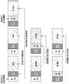
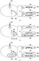
- 1is a diagram illustrating an example of a connection structure of 5G communication.
- 5G communicationsmust be designed to support a variety of access methods.
- the structure as shown in FIG. 1may be considered.
- a first base station (SeNB1 or eNB1) 120 and a second base station (SeNB2 or eNB2) 125are centralized by an OAM server (or centralized RRM (C-RRM) server) 110. It can be controlled (150, 155). Alternatively, the first base station 120 and the second base station 125 may be controlled in a distributed manner by transmitting and receiving a direct control signal between the base stations (160 and 165). In the case of distributed control between base stations, the first base station 120 and the second base station 125 may exchange control signals by wires (160) or wirelessly (165).
- the base stations 120 and 125may control such that there is no contention of resources between the terminals 130, 135, 137, 140, 145, and 147 in one base station 120 and 125.
- a case in which resources are shared between neighboring base stations 120 and 125may be considered.
- resource access based on contention based or distributed scheduled access between terminals 130, 135, 137, 140, 145, and 147 of neighboring base stations 120 and 125may be considered ( 190, 191, 193, 195).
- contention based on contention or distributed schedulingmay be considered in the uplink between one of the base stations 120 and 125 or the terminals 130, 135, 137, 140, 145 and 147 of the base stations 120 and 125. .
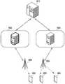
- FIG. 2is a diagram illustrating an example of resource allocation of 5G communication.
- a base stationmay be unintentionally installed when using a high-density small cell environment and an unlicensed / licensed shared band.
- orthogonal assignmentmay be performed so that resources do not overlap each other. That is, the signal 250 transmitted by the first base station 210 through the first resource allocated to the first terminal 220 is the second terminal 223 located within the coverage of the second base station 213 which is an adjacent base station. May be an interference signal 255.
- the signal 260 transmitted by the second base station 213 through the second resource allocated to the second terminal 223may be an interference signal 265 to the first terminal 220.
- orthogonal allocationmay be performed between the first base station 210 and the second base station 213 so that resources do not overlap each other.
- the same resourcemay be allocated for radio resource reuse. That is, since the second base station 213 and the third base station 215 are far apart from each other, the signal 260 transmitted by the second base station 213 through the second resource allocated to the second terminal 223 is the third. It may be difficult to act as the interference signal 267 to the third terminal 225 located within the coverage of the base station 215.
- the signal 270 transmitted by the third base station 215 through the second resource allocated to the third terminal 225may also be difficult to act as the interference signal 275 to the second terminal 223. Therefore, the same resource may be allocated between the second base station 213 and the third base station 215 for radio resource reuse.
- the present inventionconsiders a method of exchanging resource allocation information by wire or wirelessly between base stations and re-adjusting in consideration of interference amount.
- SAscheduled access
- CBAcontention-based access
- D-SAdistributed scheduled access
- CFAcontention-free access
- C-SAcentral resource allocation
- D-SAdistributed resource allocation
- the frame structure informationmay include resource access type and uplink / downlink / orientation resource allocation information. Equalization is a term for expressing a direction of a link between terminals in the form of sidelink or device to device (D2D) / Mesh.
- the frame structure informationmay include resource access type and up / down / orientation resource allocation information for a unit of time and frequency axis.
- the frame structure informationmay indicate whether the resource allocation information is fully used or partially used or not used.
- the frame structure informationmay inform the transmission power value in the resource allocation information.
- the base stationmay exchange structure information of a frame to be used by neighboring base stations through an X2 interface.
- the base stationmay exchange frame structure information to be used with the neighbor / group base station through an OAM or a mobility management entity (MME) server.
- the base stationmay exchange frame structure information with a beacon through an inter-base station control channel configured between adjacent / group base stations.
- a control channel between base stationsis configured wirelessly among the above examples.
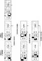
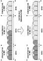
- FIG. 3A and 3Bare diagrams illustrating an example of a method of exchanging frame information between base stations according to an embodiment of the present invention
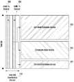
- FIG. 4is a diagram illustrating exchanging structure information of a frame according to an embodiment of the present invention.
- FIG. 1shows an example of a post frame structure.
- a first base station and a second base stationmay mutually transmit and receive beacons 350, 355, 360, and 365 in an inter-eNB coordination channel 310.
- the beacons 350, 355, 360, 365may be transmitted over the full bandwidth as illustrated in FIG. 3A, or some bandwidth as illustrated in FIG. 3B. It may be transmitted via.
- the frame structuremay be set by the beacons 355 and 365 of the first base station. That is, the centralized schedule access 320, the contention based access 323, and the distributed schedule access 325 may be set by the beacons 355 and 365 of the first base station.
- the first base stationmonitors the beacons 350 and 360 from another base station (for example, the second base station) at a time other than when the beacons 355 and 365 are transmitted in the inter-base station control channel 310 ( can be received by monitoring). Since there is a half-duplex constraint in mutual transmission and reception between base stations, signals of each beacon 350, 355, 360, and 365 should be transmitted in a time-divisionally separated manner in a TDM or CSMA / CA manner. The reserved / camped terminal should also receive the beacon signal to update the frame structure.
- the first base station and the second base station having exchanged frame structure information for the nth and n + 1th subframes 410 and 420are considered for each resource in consideration of the influence of interference and resource allocation scheme.
- the frame structure for the n + kth and n + k + 1th subframes 430 and 440may be determined by changing the allocation method or determining whether to use it. Meanwhile, when the frame structure information is exchanged between the base stations to the network, the k value may be zero. In the case of exchanging the frame structure to a control channel between base stations, the value of k may be greater than or equal to 0 since resources for the control channel between base stations are limited.
- the base stationmay classify neighboring base stations as interference targets according to reception strengths of beacons received from each other, and determine resource allocation information with the interfering base stations according to priority rules.
- the priority rulemay include a priority between resource allocation schemes and a priority between base stations. For example, when a downlink (DL) and a uplink (UL) collide, the downlink may be a high priority. As another example, when there is a collision between uplink (UL) and upstream competition (U-CA), the uplink may be a high priority. If a resource allocation scheme with the same priority collides with the same resource, the corresponding resource may be determined based on the priority between base stations.
- the beacon signals 350, 355, 360, and 365 of the base stationmay be transmitted including the priority value of the base station.
- the priority value of the base stationmay be determined by a predetermined occurrence pattern, may be determined by the MME or OAM server, or generated by generating a random value at the base station.
- FIG. 5is a diagram illustrating an example of a hybrid access and distributed schedule access method according to an embodiment of the present invention.
- a hybrid access or a distributed scheduled accessmay be configured by combining a contention based access (CBA) and a schedule access (SA). That is, the hybrid access (HA) performs signal exchange between devices in the CBA area having a small data size, and as a result, follows the procedure of transmitting in the SA area for successful competition.
- CBA Type 1is a signal exchange between the terminals
- CBA Type 2is a signal exchange between the base stations
- CBA Type 3distinguishes that the signal exchange between the terminals, between the base stations, between the terminal and the base station.
- the method of configuring a resource access methodcan be summarized as follows.
- the base stationexchanges resource allocation information including a resource access method through a beacon or a system information message, or by a wired control protocol between base stations or a control of a central server.
- the base stationdetermines the signal strength of the neighboring base station based on the reception strength of the beacon or SI or the reception strength of the synchronization / reference signal.
- the base stationevaluates the interference effect of the signal of the adjacent base station further considering the resource access method.
- the terminalreceives the beacon / SI message of the base station, to determine which resource is changed in the resource access method, according to at least one of control signal detection, data signal detection, data transmission method determination, channel measurement, energy sensing accordingly Perform
- FIG. 6is a diagram illustrating an example of transmitting a common discovery channel in a 5G communication structure according to an embodiment of the present invention
- FIG. 7is a diagram illustrating examples of allocation of a common discovery channel.
- a first base station 620 and a second base station 625may be connected to an OAM server (or (C-RRM) server) 610.
- the first terminal 630may be located within the cell coverage of the first base station 620
- the second terminal 635may be located within the cell coverage of the second base station 625.
- a common discovery channel (CDCH) 650, 651, 652, and 653is provided so that various devices including the base stations 620 and 625 or the terminals 630 and 635 can quickly exchange small information. ) May be configured.
- CDCHs 650, 651, 652, and 653may be configured in frequency, time, as illustrated in FIG. 7.
- CDCHs 650, 651, 652, and 653may be allocated at the same time between base stations as shown in FIG.
- CDCH (650, 651, 652, 653)may be allocated to a frequency as shown in (c) of FIG. 7 to configure regardless of a synchronous / asynchronous network, but since there is a half duplex problem, an additional scheduling operation is required. .
- the additional scheduling operationmay configure uplink CDCHs 651 and 652 in a separate time / frequency / code resource for transmitting signals of the terminals 630 and 635 for reception by the base stations 620 and 625.
- the downlink CDCHs 651 and 652 for transmitting signals of the base stations 620 and 625 for the terminals 630 and 635to be configured in separate time / frequency / code resources, or the base station 620, Configure the CDCH 650 for transmitting and receiving signals between 625 in a separate time / frequency / code resource, or the CDCH 653 for transmitting and receiving signals between terminals 630 and 635 for separate time / frequency / code resources. Can be configured in.
- FIG. 8is a diagram illustrating a procedure for notifying a terminal of CDCH configuration information according to an embodiment of the present invention.
- the networkmay transmit the configuration of the CDCH to the terminal 630 through a common configuration message.
- the common setting messageis a message for setting the minimum system information necessary according to the type of the terminal 630 according to the service and setting accordingly.
- the base station 620transmits a common configuration message to the terminal 620 using a) a common time / frequency resource irrespective of the terminal / service type, or b) the terminal 630 once connected to a network for each terminal / service. Can be transmitted through a control channel or a data channel of each connected network (individual radio access technology (RAT)).
- RATindividual radio access technology
- the common configuration messagemay include at least one of RAT (service, slice) information and RAT (service, slice) ID for the terminal.
- RATservice, slice
- RATservice, slice
- the terminal 630may monitor whether the condition for transmitting the RAT discovery signal is satisfied in step 820. After that, if the condition for transmitting the RAT discovery signal is satisfied, in step 830, the terminal 630 transmits a RAT discovery request signal to the base station 620 on the CDCH set in the common configuration message. can do.
- FIG. 9is a diagram illustrating another example of a procedure for notifying the terminal of CDCH configuration information according to an embodiment of the present invention.
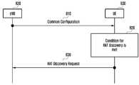
- the terminal 630may receive a common configuration message from the first base station 620 in step 910. Based on the received common configuration message, the terminal 630 may transmit a RAT discovery request message to the second base station 625 in steps 920 to 940.
- the process of selecting the base station 625 to which the terminal 630 sends the RAT discovery request messageincludes cell (re) selection through quality measurement of the synchronization signal and the reference signal of the base stations 620 and 625. Operation and camped cell selection may be made. In the process of selecting a camped cell, the terminal 630 may optionally check the common configuration message once more in step 930.
- the base stations 620 and 625may include version information in the common configuration message and transmit the version information to the terminal 630 so that the terminal 630 cancels the reception operation for the common configuration message having the same version.
- the first base station 620 and the second base station 625are generally physically separated base stations, different divided higher layer networks (ie, RATs or slices) within physically identical base stations. It may be a virtual base station belonging to.
- 10 to 17are diagrams illustrating an example of a shortening process of an initial / arbitrary access process of a terminal according to an embodiment of the present invention.
- the CDCHmay be used to shorten the random access procedure of the terminal 630.
- the terminal 630may transmit a RAT discovery request message including service information requested by the terminal 630 to the base station 620 through the CDCH.
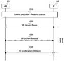
- the base station 620may inform a) implicitly or b) explicitly of a location to transmit system information information corresponding to the service of the terminal 630 together with the RAT discovery response message.
- the base station 620transmits system information (SI) configured for the terminal 630 at the informed location.
- SIsystem information
- the RAT discovery request message in step 1710causes a random access channel (RAC) operation 1750
- the base station 320determines the ID and general information for transmission on the network to be used by the terminal 630, 1740 In step, it may inform the terminal 630 in a UE-specific configuration message.
- the UE-specific configuration messagemay be transmitted through the resource region set in the system information.
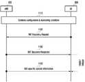
- step 1010the base station 620 transmits the configuration of the CDCH to the terminal 630 via a common configuration message, the terminal 630 receiving the common configuration message It may be monitored whether a condition for transmitting the RAT discovery request signal is satisfied. If the condition is satisfied, the terminal 630 may transmit a RAT discovery request message to the base station 620 in step 1020.
- the base station 620transmits the RAT discovery response message and the SI related to the RAT requested by the terminal 630 to the terminal 630 at the same time in response to receiving the RAT discovery request message from the terminal 630.
- the terminal 630receives the transmission position of the RAT-specific SI (RAT-specific SI) is determined in advance, depending on the location of the resource receiving the RAT discovery response message, or the resource that sent the RAT discovery request message It can be determined depending on the position of.
- step 1110 or 1210the base station 620 transmits the configuration of the CDCH to the terminal 630 through a common configuration message, and the terminal 630 receiving the common configuration message has a condition for transmitting a RAT discovery request signal. You can monitor whether you are satisfied. If the condition is satisfied, the terminal 630 may transmit a RAT discovery request message to the base station 620 in step 1120 or 1220.
- the base station 620may transmit an SI related to the RAT requested by the terminal 630 and the RAT discovery response message at different times in response to the reception of the RAT discovery request message of the terminal 630. That is, the base station 620 transmits a RAT discovery response message to the terminal 630 in step 1130 or 1230, and transmits an SI related to the RAT requested by the terminal 630 to the terminal 630 in step 1140 or 1240. have.
- a transmission position of the RAT-specific SIis determined in advance, or is determined depending on the location of a resource receiving the RAT discovery response as illustrated in FIG. 11, or illustrated in FIG. 12. As described above, it may be determined depending on the location of the resource that sent the RAT discovery request. In the case of FIG. 12, the transmission of the RAT discovery response message may be omitted or delayed to the next time point.
- step 1310the base station 620 transmits the configuration of the CDCH to the terminal 630 through a common configuration message, and the terminal 630 receiving the common configuration message monitors whether a condition for transmitting a RAT discovery request signal is satisfied. can do. If the condition is satisfied, the terminal 630 may transmit a RAT discovery request message to the base station 620 in step 1320.
- the base station 620may transmit an SI related to the RAT requested by the terminal 630 and the RAT discovery response message at different times in response to the reception of the RAT discovery request message of the terminal 630. That is, the base station 620 transmits a RAT discovery response message to the terminal 630 in step 1330, and transmits an SI related to the RAT requested by the terminal 630 to the terminal 630 in step 1340.
- the location of the RAT-specific SIis divided into a location of a resource designated by the base station 620 through the RAT discovery response message or an indicator for each terminal 630 provided through the RAT discovery response message. It may be the location of the resource indicated by the control channel for each terminal 630 of 620.
- the common configuration message of the base station 620is configured to the terminal 630 through common system information or a control channel of a separate RAT (when previously connected to a specific RAT).
- the terminal 630may transmit a RAT discovery request message to the base station 620 in step 1420 using RAT common resources.
- the base station 620may transmit a corresponding RAT configuration and related system information (SI) to the terminal 630 as a broadcast channel or an allocation channel for each terminal 630 according to a request of the terminal 630.
- SIsystem information
- the base station 620transmits configuration information for each terminal for RAT access and transmission / reception of the terminal 630 or a RAT discovery response message including the information to the terminal 630.
- the common configuration informationalready includes resource configuration information for receiving a RAT-specific UE-specific configuration or RAT discovery response message, the procedure of transmitting or receiving the RAT-specific SI may be omitted.
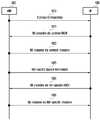
- the base station 620 and the terminal 630may transmit configuration information for each terminal by using a random access (RA) procedure.
- RArandom access
- the RA procedure in the existing specific RAT connectionmay be simplified by utilizing an RA preamble signal transmitted by the terminal 630 and an RA response message transmitted by the base station 620. That is, in step 1510, the common configuration message of the base station 620 is configured to the terminal 630 through common system information or a control channel of a separate RAT (when previously connected to a specific RAT). In step 1520, the UE 630 may transmit the RA preamble on a common RA channel found to have a common configuration. In operation 1550, the base station 620 may transmit a RA response message to the terminal as a RAT-specific resource.
- the UE 630 additionally receiving the RAT-specific SIis transmitted to the base station 620 as a RAT-specific RACH (RAT-specific RACH) in step 1540.
- the RA preamble signalmay be further transmitted.
- the base station 620may transmit a corresponding RAT configuration and related system information (SI) to the terminal 630 according to a request of the terminal 630.
- SIsystem information
- the terminal 630may calculate the RA-RNTI for each RAT that can be distinguished in association with the RA preamble transmitted and received on a common resource or CDCH. It should be possible.
- the existing RA-RNTIis obtained by the following [Equation 1].
- RA-RNTI1 + t_id + 10 * f_id
- t_idis a RACH resource divided by a time axis
- f_idis a RACH resource divided by a frequency axis.
- F_idis set only in TDD
- f_idis set to 0 in FDD. Since the RACH resource is set for each subframe, t_id actually corresponds to the subframe index. According to LTE, t_id corresponds to 10 subframes constituting one frame, that is, has a value of 0 to 9. That is, it can be seen that the classification of the RA-RNTI is distinguished by the index of the RACH resource that transmitted the RA preamble.
- the structure and setting of common resources between RATs and resources for each RAT illustrated in the present inventionmay be completely different. Therefore, the understanding of the existing RA preamble transmission resources, that is, the understanding of the configuration of the RACH resources may be different for each RAT, a) based on variables explicitly provided by the terminal 630 for RA-RNTI determination, or b) based on a formula for converting the RA-RNTI obtained in the common RA procedure into a RA-RNTI for a RAT-specific RA procedure; RA-RATI per RA can be determined.
- the terminal 630transmits a random value obtained within a specific range based on common configuration information through a-1) RA request message, or a- 2) Sending a combination of RAT-specific variables (for example, prime numbers) and any number provided in the common configuration information through a RA request message, or a-3) RAT provided in the common configuration information
- RAT-specific variablesfor example, prime numbers
- the terminal 630compares b-1) common RA configuration with RA setting for each RAT to determine the RACH resource in the closest RA for each RAT corresponding to the time point in which the actual common RACH was transmitted.
- the RA-RNTIis determined based on the determined index of the RACH resource, or b-2) a logical RACH resource order (for example, time, frequency, time-frequency) is compared with the common RA setting and the RA setting for each RAT.
- the RA-RNTImay be determined based on the logical resource index in the RAT-specific RA corresponding to the logical resource index transmitted in the common RACH.
- the common RA configurationis composed of 10 subframes and 8 frequency resource blocks (RBs)
- the RA preambleis transmitted in the second frame
- the RA configuration for each RATis 3 subframes. If it is composed of a frame and four frequencies RB, t_id, f_id, or t_f_id for each RAT can be determined by Equation 2 and Equation 3 as follows.
- RAT_f_id⁇ Common_f_id ⁇ Mod
- Max_RAT_RBs⁇ Common_f_id ⁇ Mod 4
- operations of the terminal 630 and the base station 620may complete the RA preamble / response procedure in common resources in steps 1610 to 1620. Then, the terminal 630 receives the RAT-specific SI in step 1625 through a separate process from the base station 620 to confirm the RA resource setting for each RAT, if the RA procedure start conditions in the corresponding RAT, step 1630 and In step 1635, the RA preamble / response procedure may be performed through the RAT-specific RACH / resource.
- an operation of transmitting the SI for each RAT to the terminal 630 by the RAT response message in a common resourceis different from that in FIG. 16A. That is, the RA preamble / response procedure may be completed in common resources in steps 1650 to 1660. At this time, the base station 620 may transmit a RAT response message and SI for each RAT to the terminal 630. In addition, the UE 630 may check RA resource setting for each RAT, and if the RA procedure start condition is met in the corresponding RAT, the RA preamble / response procedure may be performed through RAT-specific RACH / resource in steps 1665 and 1670. .
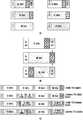
- FIG. 18is a diagram illustrating a method for a low latency communication service according to an embodiment of the present invention.
- a framemay include a downlink 1810 configured as a scheduled access (SA) and an uplink 1820 configured as a content-based access (CBA). have.
- SAscheduled access
- CBAcontent-based access
- the terminal 630may receive downlink data.
- the terminal 630may post an ACK message for receiving downlink data in step 1840.
- the terminal 630 and the base station ( 620may quickly perform the next transmission (step 1850).
- the transmission time interval (TTI)is a unit indicating one transmission interval.
- the base station 620may inform the base station 620 according to at least one of the following operations.
- 5G communicationneeds to be designed in consideration of a new metric such as delay compared to an existing scheduler.
- a new metricsuch as delay compared to an existing scheduler.
- the case in which resource regions are divided according to a class of the terminalshould be considered.
- 19A to 19Cillustrate an example of a scheduling procedure.
- the base station 620collects the measurement results 1910, 1915, 1950, 1951, 1952, 1953, 1960, 1961, and 1962 of the base station 620 or the terminal 630.
- the proportional fairness metricis calculated based on the radio state (1920) and the transmitted bit rate (1925), and the scheduler (1930) based on the resource quantity (PRB) and MCS (modulation & coding scheme) index (1935).
- PRBresource quantity
- MCSmodulation & coding scheme
- FIG. 20is a diagram illustrating an example of a scheduling procedure according to an embodiment of the present invention
- FIG. 21is a diagram illustrating another example of a scheduling procedure according to an embodiment of the present invention.
- the schedulermay be modified as an example.
- the terminal 630may receive resource allocation by an appropriate sub scheduler 2040, 2043, 2045 according to the type of traffic or service.
- Each sub scheduler 2040, 2043, 2045is varied by a combination of several metrics.
- the calculation results of the sub schedulers 2040, 2043, 2045are again integrated and adjusted by the scheduler 2050.
- the scheduler 2050may perform the final resource allocation and the MCS determination 2060. Configurations not described in this figure are similar to the operation of the configuration described in the section related to FIG.
- the sub schedulers 2080, 2083, and 2085 for each servicemay allocate resource allocation and MCSs 2090, 2093, and 2095 for each terminal. You can decide. Configurations not described in this figure are similar to the operation of the configuration described in the section related to FIG.
- each terminal 630needs to report necessary metrics such as channel measurement, required delay, and power consumption for the sub-schedulers 2040, 2043, 2045, 2080, 2083, and 2085 for a specific purpose.
- the base station 620 or the networkmay set the format of the reporting control signal for each slice, for each bearer, or for each PDU upon initial access or RRC establishment of the terminal 630. Even the control signals for reporting of the same physical layer may actually indicate information depending on the setting of the reporting format.
- the terminal 630configures and transmits a reporting control signal to the base station 620 according to the report format set at the time of initial access, and operates the set format before the base station 620 changes the report format by RRC reconfiguration. have.
- the terminal 630since the terminal 630 may be receiving a plurality of services, the terminal 630 may transmit a scheduler ID for identifying the scheduler 2050 at the time of reporting, or report resources may be set for each scheduler ID. Can be.
- the present inventionproposes a method of composing an entire frame by combining basic subframes having a minimum building block type according to a modularization principle.
- FIG. 22is a diagram illustrating an example of a subframe configuration according to an embodiment of the present invention
- FIG. 23is a diagram illustrating an example of a frame structure according to an embodiment of the present invention.
- a framemay be configured based on four different shapes of subframes.
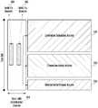
- the four subframesmay be configured with downlink (DL) 2210, uplink (UL) 2220, DL-GP-UL 2230, and UL-DL 2240 (or DL-UL), respectively.
- a guard period (GP) in the DL-GP-UL 2230is required in consideration of the margin for the UL to advance timing for synchronization with the base station when the base station transmits the downlink and then switches to the uplink.
- a very small RF transition timesevere to several tens of us
- the base stationbundles a plurality of subframes into one resource as well as the resource allocation for each subframe 2210, 2220, 2230, 2240 (2330). 2350) may be allocated to the terminal.
- the DL partmay be allocated to the terminal in the partial DL subframe 2310 and the UL part may be allocated to the terminal in the partial UL subframes 2320 and 2340.
- the DL portions of the two DL subframes 2210 and the DL-GP-UL 2230 subframesmay be bundled into one resource and allocated to the UE as a concatenated DL subframe 2330.
- the UL part of one UL subframe 2220 and the UL-DL subframe 2240may be bundled into one resource and allocated to the UE as the connection UL subframe 2350.
- Information of the bundled connection subframes 2330 and 2350may be included in a control signal for DL assignment or UL grant.
- the physical layermay inform the format of the subframes 2330 and 2350 bound to the MAC layer to assist scheduling when subframes of different lengths are connected, or may indicate the number of symbols / bits available in the entire transmission unit. .
- the cross talk problemmay be a problem in both the downlink of the serving base station and the uplink of the neighboring base station or the collision of the uplink of the serving base station and the downlink of the neighboring base station.
- interference in the control signalcan greatly affect the system.
- a method of constructing a flexible frame based on a minimum form for reducing interference in a control signalis considered. This is called atomic design for convenience.
- the downlink control signalis used for scheduling assignment, grant or ACK transmission for the uplink.
- the uplink control signalis used for scheduling request, buffer status report, ACK transmission for downlink, and sounding reference signal (SRS).
- SRSsounding reference signal
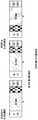
- 24 to 32illustrate examples of a configuration of a subframe according to an embodiment of the present invention.
- this atomic design structurehas the advantage of having a DL and UL control channel in every subframe so that the control channel can be used quickly whenever necessary.
- the base stationtransmits a HARQ-ACK / NACK signal for DL data transmission in the kth subframe in the UL control channel (or piggybacks the UL data channel) of the k + nth subframe.
- the n valuemay be calculated (scheduled) to be transmitted and informed to the DL control channel of the k-th subframe indicating DL data transmission.
- the base stationindicates the UL grant for the UL data transmission of the terminal to the DL control channel of the k-th subframe, and the terminal to send the UL data signal for this UL grant in the k + nth subframe n
- the valuecan be calculated (scheduled) and informed with the UL grant.
- the base stationschedules the HARQ-ACK / NACK signal for the UL data transmission of the k-th subframe to be transmitted on the DL control channel (or piggybacked DL data channel) of the k + n-th subframe by the k-th subframe. It may be indicated by a UL grant or an RRC control signal indicating the UL data transmission of the frame.
- the base stationmay instruct resource allocation for a plurality of subframes in a kth subframe and then perform a cancellation / change instruction on the preallocated resource in a k + nth subframe.
- the changemay include a transmission time point, a transmission method, a physical layer time / frequency resource and a subframe structure at the time of transmission.
- the base stationmay determine the resource location of the UL signal such as SR, BSR, SRS of the terminal in a modular operation with respect to the system time (for example, frame / subframe number) or the base station is explicit to the terminal. You can tell it dynamically.
- a) a time point configured as RRC or SI as the DL control signal of the physical layerMay indicate an additional offset to, b) cancel the closest specific UL control signal time point, or c) change the closest specific UL control signal time point.
- positions of the DL control signal DL cnt and the UL control signal UL cnt in one subframemay be the same in time or / and frequency.
- a subframemay be configured in the order of DL control channel (DL cnt) / gap (GP) / UL control channel (UL cnt) / data.
- DL cntDL control channel
- GPgap
- UL cntUL control channel
- datadata
- a HARQ-related variablesuch as a format for the UL data and a HARQ process ID may be first transmitted in the UL control channel to provide a degree of freedom for the base station to receive UL data at any time.
- the operation of transmitting the UL control channel or UL data after UL LBTmay give priority to transmission of the UL control channel.
- the UL control channel DL cntis a DL control channel DL cnt in addition to an advantage obtained by collecting the control channels DL cnt and UL cnt as compared to the subframe illustrated in FIG. 24. Since the position is prioritized, the terminal transmits a reference signal such as SRS so that the base station can complete the channel measurement early. In the TDD situation, since the DL and the UL use the same band, the base station may determine the DL data or the modulation & coding scheme (MCS) for the UL data as the UL reference signal according to the channel reciprocity characteristic. The base station may apply to data transmission of the nth or subsequent subframes when there is the same subframe or processing delay as that of receiving the UL reference signal according to the measurement result for the UL reference signal RS.
- MCSmodulation & coding scheme
- the DL control channel DL cnt and the DL data channel DLare concatenated, and the UL data channel UL data and UL control channel are concatenated.
- (UL cnt)can be concatenated. By doing so, it may be easy to apply when a data transmission / reception operation should immediately follow the control channel transmission / reception.
- the last DL control channel DL cntmay be additionally located.
- HARQ ACK / NACK for UL datacan be transmitted and received on the last DL control channel (DL cnt) of the same subframe.
- the positions of the DL control signal DL cnt and the UL control signal UL cnt in one subframeare not the same in time or / and frequency, but rather with the relative gap period GP. Can match.
- Operating these subframes between network / base stations that are in synccan reduce interference for at least the DL control channel and the UL control channel.
- the systemmay inform the terminal of length information of the gap section directly or as an ID of a subframe configuration set.
- the base stationmay indicate the length of the gap section as zero.
- a subframeis divided into DL subframes and UL subframes. That is, the subframe may be configured in the form of DL control channel (DL cnt) / gap (GP) / DL data (DL data) and gap (GP) / UL control channel (UL cnt) / UL data (UL data).
- DL cntDL control channel
- GPgap
- UL cntUL control channel
- the channelmay be located.
- the newly added control channelmay be arranged to overlap the gap (GP) so that there is no DL and UL mutual interference.
- the interference amount for a desired control channelmay be adjusted by adjusting the length of the gap section GP.
- the UL control channel UL cntmay be deleted, the position of the gap GP may be sent to the back, the gap GP may also be deleted, and the like. have. Even with such a change, there is an advantage that the interference caused by the UL control channel (UL cnt) signal can be absorbed in the gap GP, as illustrated in (b) of FIG. 31.
- 31Aalso illustrates a case where the DL control channel DL cnt is allocated to some bands rather than all bands.
- TTI and duplexare fixed (3110), dynamic TTI and fixed duplex (3120), fixed TTI and dynamic duplex (3130), or both TTI and duplex are dynamic 3140.
- the base stationmay indicate a basic TTI mode (normal TTI) with an RRC signal.
- the base stationmay inform in advance whether the n + kth subframes in the next n are to be operated as a short TTI through the L1 (physical layer) signal in the DL control channel of the normal TTI. have.
- a potential position of one or more TTI modesmay be indicated by an RRC signal.
- the base stationmay indicate the normal TTI configuration and the short TTI configuration, respectively, by the RRC signal.
- the determination of the actual TTI modeis performed in advance in which TTI the next n to n + kth subframes (calculated based on the current TTI mode) are to be operated through the L1 signal in the DL control channel already indicated by the specific TTI mode.
- the L1 signal for each of the plurality of TTI modesmay inform in advance which TTI the next n to k + th subframes (calculated based on the corresponding TTI mode) will operate.
- the present inventionprovides a method of informing the information of the next frame in every frame.
- the downlink control signal of the DLfor example, the higher layer signal of the PDCCH or PDSCH
- the information of the next framemay be the number of subframes and the subframe format of each subframe.
- the absolute value of the starting point of the frame or the relative value from the reference point of the indicating framemay be informed.
- a gap frame / subframemay be introduced to indicate a new empty frame / subframe.
- itmay indicate how many times the configuration of the next indicated frame will be repeated. If the terminal has not been instructed whether to repeat the next frame, it may be understood that the configuration of the last-instructed frame is repeated indefinitely until a new instruction comes.
- a detailed methodwill be described.
- 33 and 34illustrate examples of a method of indicating next frame information according to an embodiment of the present invention.
- AT1 or AT2represents type 1 and type 2 of one building block according to atomic design.
- AT1 and AT2may include DL data or UL data determined according to scheduling of the base station.
- the configuration of AT1 and AT2can be selected so that the gap (GP) is located at the front in AT2 and at the back in AT1.
- a separate gap indicationmay be included in the frame configuration to indicate the gap position of FIG. 33 (a).
- AT1should be a subframe including at least a DL control channel, and the base station can instruct the terminal of the frame configuration after the next nth subframe or kth frame through the DL control channel.
- AT1 or AT2represents type 1 and type 2 of one building block according to atomic design.
- AT1 and AT2may include DL data or UL data determined according to scheduling of the base station.
- the configuration of AT1 and AT2may be selected so that the gap is located at the front in AT2 and at the back in AT1, or the gap may be indicated by including a separate gap indication in the frame configuration.
- AT1should be a subframe including at least a DL control channel, and the base station can instruct the terminal of the frame configuration after the kth frame through the DL control channel. Meanwhile, in the case of FIG.
- the base stationcan inform the terminal of the periodic time point in advance with the RRC signal or SI, and can perform scheduling and control so that the next frame configuration indicator can be transmitted according to the time point.
- the existing frame setting contentsmay be overwritten by the recently received frame setting contents. This means that content for the same frame is updated and new frames are added. If the frame indexes do not match, the same principle may be applied in units of subframes. That is, contents of the same subframe may be updated and new subframes may be added.
- the base stationmay instruct the terminal as information about a frame (or subframe) for receiving a sync signal, a reference signal, or a paging message as an RRC signal or system information (SI).
- the base stationmay also indicate the RACH resource for receiving the RA preamble signal of the terminal as an RRC signal or system information (SI).
- the common sync signal required for the initial access of the terminalmay be set in advance in the terminal or may be set in the terminal through a signal including a separate control signal or SI information from another network.
- the terminalshould determine if the UL data transmission indicated by the existing UL grant is affected by the changed frame / subframe configuration. Possible operation methods may be based on at least one of the following. 1) If the UL data transmission time point indicated by the UL grant belongs to the changed frame / subframe, the UL data transmission is canceled. 2) If the UL data transmission time point indicated by the UL grant is changed to DL data transmission by the changed frame / subframe, the UL data transmission is canceled. 3) If the UL data transmission time point indicated by the UL grant is configured as UL data transmission despite the changed frame / subframe, the UL data transmission is not canceled. 4) Despite the frame / subframe in which the UL data transmission point indicated by the UL grant is configured as UL data transmission, when the variable affecting transmission and reception such as the subframe length is changed, the UL data transmission is cancelled.
- the base stationmay indicate a separate UL grant having a shorter UL grant-UL data delay than the conventional UL grant or a UL grant including the delay value for the canceled UL data transmission. . This may be called fast UL data retransmission.
- the UEdoes not discard the data block in the buffer but if the base station receives an UL grant for the same HARQ process ID, the terminal reuses the data block stored therein and transmits the data block. can do.
- the time that the terminal stores the data block in this operationmay be an implementation, but in order to facilitate the scheduling operation of the base station, the base station may indicate a separate buffer storage time or operate by limiting the length of the frame.
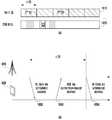
- 35is a diagram illustrating an example of dynamic burst scheduling according to an embodiment of the present invention.
- Resources for data bursts and other signalsare allocated by a single indication of configuration parameters such as timing and RBs.
- a type-1 DBSdata burst and feedback are allocated to a single PDCCH.
- initial transmissions and re-transmissionsare assigned to a single PDCCH.
- the base station eNBoverwrites existing assignments for the DL or priority-based shared UL Resources-based shared UL resources may be allocated.
- Type-3 DBSIn the third type (Type-3) DBS, multiple data bursts are allocated to a single PDCCH.
- Both DL data bursts and UL data burstsmay be indicated together.
- Each DBS typemay be combined according to traffic properties and service requirements (eg, high reliability or low latency usages, etc.).
- the DCI formatmay include, for example, at least the following information according to the type.
- Type-1 DBSDL assignment for DL data
- the information of the following [Table 1]may be included.
- Type-1 DBS(UL grant for UL data), it may include information of the following [Table 2].
- retransmission resourcesmay be indicated similarly to the format of Type-1 DBS, but since retransmission resources are not determined to be transmitted, 1) a plurality of terminals are shared, or 2) a plurality of Sharing for HARQ process ID, 3) sharing for transmission of the same HARQ process ID in a plurality of subframes;
- the efficiencymay be improved by at least one method. Therefore, in the case of Type-2 DBS, in addition to the information required for Type-1 DBS, at least one of the contents of Table 3 below may be added.
- Type-3 DBSis similar to conventional multi-subframe scheduling in which a plurality of subframes are allocated with one UL grant or DL assignment, but also allocates feedback resources for HARQ-ACK / NACK.
- Feedbackmay be separately indicated for each data burst (or packet), but only the location of the feedback resource for the first transmission may be separately indicated for efficient use of DCI resources.
- resource burstscan be used to reduce delays in the allocation of feedback resources or new-tx packets and re-txs in order to reduce the allocation delay of retransmission resources. ) Can be scheduled according to both data and FB as well as all packets.
- the base stationmay instruct the terminal through one resource mapping pattern among preset resource sets.
- the resource mapping patternmay include RB allocations, periods, data / FB, MCS, and the like.
- Resource pre-assignment for retransmissioncan result in a waste of resources.
- a resource sharing schemecan be considered.
- blocks denoted by 3510, 3520, and 3530 in FIG. 35indicate resource allocation for the first terminal, the second terminal, and the third terminal, respectively.
- the circled numbersalso indicate initial transmission and retransmission.
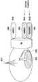
- 36is a diagram illustrating an example of a service providing structure of 5G communication according to an embodiment of the present invention.
- an unlicensed band 3655may be used as a backup for the ultra-high frequency (mmWave) band 3650 in 5G communication.
- the second base station (eg, SeNB) 3620is moved to the unlicensed band 3635 by the report of the terminal 3630. Switching can mitigate link performance reduction. This is because the unlicensed band 3555 has less attenuation than the mmWave band 3650 and can secure a wider bandwidth than other licensed bands 3660.
- a first base station (eg, MeNB) 3610 and a second base station (SeNB) 3620may be integrated.
- the second base station (SeNB) 3620may have two switchable spectrums (eg, an ultra-high frequency (mmWave) band 3650 and an ISM 5 GHz band 3655).
- the UE 3630may be serviced by the frequency band 3660 of the first base station (MeNB) 3610 and the ultra-high frequency band 3650 of the second base station (SeNB).
- the terminal 3630is the frequency band 3660 of the first base station (MeNB) 3610 and ISM 5GHz (3655) of the second base station (SeNB) ) Can be serviced.
- the very high frequency band 3650 linkmay be broken due to high attenuation.
- the ISM 5GHz band 3655may have better link properties than the ultrahigh frequency band 3650 in an attenuation perspective.
- switching in the ultra-high frequency band 3650 and the ISM 5 GHz band 3655is performed by the frequency band of the first base station 3610 (eg, sub6 GHz) 3660 or the ISM 5 GHz band of the second base station 3620. Triggered via 3655.
- FIG. 37 and 38are diagrams illustrating a method for a UE to report RLF (Radio Link Failure) of an ultra-high frequency band according to an embodiment of the present invention
- FIG. 39is a subframe for reporting an RLF of an ultra-high frequency band to a terminal; A diagram showing examples of the structure.
- the UE 3630may perform a Radio Link Failure (RFF) report 3710 of the mmWave 3650 through the MeNB 3610. That is, in FIG. 37A, the terminal 3630 may receive a service through the ultra-high frequency band 3650 of the second base station 3620. At this time, as shown in (b) of FIG. 37, the performance of the link 3700 between the UE 3630 and the ultra-high frequency band 3650 of the second base station 3620 may be reduced (for example, may be broken). . In this case, the terminal 3630 may make an RLF report 3710 to the first base station 3610. Accordingly, as shown in (c) of FIG.
- RLFRadio Link Failure
- the first base station 3610may transmit a message 3720 to the second base station 3620, which triggers the ultra-high frequency band 3650 to serve in the unlicensed band 3635. have.
- the terminal 3630may receive a service through the unlicensed band 3555 of the second base station 3620.
- FIG. 38may allow a UE 3630 to report a Radio Link Failure (RLF) of the mmWave 3650 through the SeNB 3620. That is, in FIG. 38A, the terminal 3630 may receive a service through the ultra-high frequency band 3650 of the second base station 3620. In this case, as shown in (b) of FIG. 38, the performance of the link 3800 between the UE 3630 and the ultra-high frequency band 3650 of the second base station 3620 may be reduced (for example, may be cut off). . In this case, the terminal 3830 may make an RLF report 3810 to the second base station 3620. Accordingly, as shown in (c) of FIG. 38, the second base station 3620 may provide a service to the terminal 3630 through the unlicensed band 3555. Such a method may be faster than a method of going through the MeNB 3610 illustrated in FIG. 37.
- RLFRadio Link Failure
- the UE 3630in order for the UE 3630 to report quickly to the second base station (SeNB) 3620, the UE 3630 should be designed to enable fast uplink transmission despite the LBT regulation in the unlicensed band 3635.
- the base station 3620may transmit a polling signal P at a specific period in a specific carrier in consideration of service requirements.
- the polling signalmay be composed of existing PSS / SSS and CRS / CSI-RS or DRS. Since the polling signal of the base station 3620 consumes a very small time interval, the base station 3630 may send a polling signal at a relatively small period despite the LBT regulation. In addition, a specific channel sensing operation is not required to send an uplink signal after a predetermined gap GP for the polling signal of the base station 3620.
- the terminal 3630which has undergone the RLF of the sudden mmWave link can monitor the polling signal in the unlicensed band (3655).
- the UE 3630may transmit an RLF failure report to the base station 3620 or perform a general random access procedure in a RACH resource that is previously set or informed by a polling signal.
- FIGS. 41 and 42are views illustrating operations when sharing frequency according to an embodiment of the present invention.
- MVNOmobile virtual network operator
- MNOmobile network operator
- MNO2mobile network operator
- MNO2mobile network operator
- eNB1first base station
- MNO2second base station
- MNO2second MNO
- the MVNO 4010 or the platform providermay lease a network of the two MNOs 4020 and 4025 to provide certain services to the first to third terminals 4040, 4043, and 4045.
- MVNO 4010In terms of MVNO 4010, not only the network of MNO1 4020 and MNO2 4025, but also the frequencies of each MNO 4020 and 4025 are leased. 4020, 4025) It is possible to improve the quality of communication service by adjusting the usage ratio for each.
- each of the MNO1 4020 and the MNO2 4025may have a 60 GHz band for sharing in addition to the 30 MHz band exclusively allocated to each of the MNO1 4020 and the MNO2 4025.
- the MVNO 4010may control to use the 50 MHz among the 60 MHz resources, which are shared resources, in the eNB2 4035.
- This methodmay be generally considered when frequency sharing is performed in a carrier unit (for example, 10 MHz unit).
- a time sharing schememay be considered in units of several ms.
- a temporal frequency sharing techniquemay be applied.
- a sharing schememay be applied in addition to the existing Rel-12 dual connectivity (DC).
- DCRel-12 dual connectivity
- MeNB and SeNBhave independent schedulers. This is often more meaningful when the MeNB and SeNB are in different locations and are connected by non-ideal backhaul links.
- the MeNB using 2.5 GHz and the SeNB using 3.5 GHzmay be separated in frequency because they are not connected by the ideal backhaul link (4210).
- a temporal sharing methodcan be applied.
- the 3.5 GHz bandmay be made available to the MeNB (DC + MeNB CA) 4220.
- the shared access methodcan be applied at 3.5 GHz to prevent resource collision and interference.
- the shared access schememay simply follow listen-before-talk (LBT) or carrier sensing multiple access / collision avoidance (CSMA / CA) used in the unlicensed band.
- the shared access schememay be an efficient resource sharing connection based on an explicit protocol between base stations.
- the SeNBmay also apply the CA to allow the SeNB to use the 2.5 GHz band (DC + MeNB CA + SeNB CA) 4230.
- the MeNBsince the MeNB needs to protect its operation at 2.5 GHz, the MeNB uses a general centralized resource access method, and only the SeNB can use the opportunistic 2.5 GHz band.
- a method of supporting resource access by explicit signal exchangemay be considered rather than a sensing-based resource access method such as the existing LBT.
- the base stationmay inform other base stations of information including a cell ID or a PLMN ID through a preamble signal (for example, an initial signal or a reservation signal) or a broadcast channel.
- the base stationreceives the cell ID or PLMN ID of the neighboring base station to know its existence.
- the base stationmay also provide information for resource sharing with or with the signal.
- the information for resource sharingmay include, for example, at least one of a start time and length of a resource to be used, a frequency of a resource to be used, a variable for resource access, and a transmission power.
- the variable for resource connectionmay be, for example, the size of a contention window in a contention-based connection.
- the base stationmay determine the size of the resource to be used based on the resource allocation amount for each base station configured in the network. For example, if the first base station and the second base station are configured to allocate resources at a ratio of 1: 2, the first base station performs resource access for 5 ms and the second base station performs resource access for 10 ms. Can be. Of course, if the first base station is not aware of the activity of the second base station, the first base station may use resources as needed without restriction. As another example, when the first base station and the second base station are configured to allocate resources at a ratio of 1: 2, the first base station may be controlled to use a contention window of 16 and the first base station may use 32 contention windows. Can be. At this time, the transmission-related variables such as the amount of all the time / frequency resources, parameters necessary for the resource access method, transmission power, the number of retransmissions may be the target of control.
- the transmission-related variablessuch as the amount of all the time / frequency resources, parameters necessary for the resource access method, transmission power
- the base stationmay inform a resource section not to be used in addition to the resource section to be used by the base station.
- Thiscan be called occupancy and vacancy signals.
- the base stationmay indicate the start of the resource and its length by displaying the occupancy / vacancy indicator as 1 bit.
- the occupancy signalmay include only downlink resources, include downlink and uplink resources, or include downlink, uplink, and uplink resources.
- an identifier for distinguishing itmay be further provided.
- FIG. 43is a block diagram illustrating a terminal according to an embodiment of the present invention.
- a terminalmay include a transceiver 4320 and a controller 4310 for controlling overall operations of the terminal.
- the controller 4310 of the terminalcontrols the terminal to perform any one of the above-described embodiments. For example, the controller 4310 transmits a radio access technology (RAT) discovery request (RAT) discovery request (RAT discovery) message to a base station through a common discovery channel (CDCH), and then a RAT discovery response (RAT discovery) from the base station.
- the systemmay receive a response message and system information related to the RAT, and receive a UE-specific configuration message from the base station through a resource region set according to the system information.
- the transceiver unit 4320 of the terminalmay transmit and receive a signal according to any one of the above-described embodiments.
- the transceiver 4320may include a transmitter 4323 for transmitting a signal to another network entity, and a receiver 4325 for receiving a signal from another network entity.
- the transceiver 4320 of the terminalmay transmit a RAT discovery request message to the base station, and receive a RAT discovery response message, an SI, and a UE-specific configuration message from the base station.
- the controller 4310 and the transceiver 4320are not necessarily implemented as separate devices, but may be implemented as a single component in the form of a single chip.
- 44is a block diagram illustrating a base station according to one embodiment of the present invention.
- a base stationmay include a transceiver 4420 and a controller 4410 for controlling overall operations of the base station.
- the controller 4410 of the base stationcontrols the base station to perform any one of the above-described embodiments.
- the controller 4410may receive a radio access technology (RAT) discovery request (RAT discovery) message from a terminal through a common discovery channel (CDCH) and transmit a RAT discovery response to the terminal.
- RAT discoveryradio access technology
- a response message and system information related to the RATand transmit a UE-specific configuration message to the terminal through a resource region set according to the system information.
- the transceiver 4420 of the base stationmay transmit and receive signals according to any one of the above-described embodiments.
- the transceiver 4420may include a transmitter 4423 for transmitting a signal to another network entity, and a receiver 4425 for receiving a signal from another network entity.
- the transceiver 4420 of the base stationmay receive a RAT discovery request message from the terminal and transmit a RAT discovery response message, an SI, and a UE-specific configuration message to the terminal.
- the controller 4410 and the transmitter / receiver 4420are not necessarily implemented as separate devices, but may be implemented as a single component in the form of a single chip.
- the operations of the base station or the terminal described abovecan be realized by providing a memory device storing the corresponding program code to any component in the base station or the terminal device. That is, the controller of the base station or the terminal device can execute the above-described operations by reading and executing the program code stored in the memory device by the processor or the central processing unit (CPU).
- the controller of the base station or the terminal devicecan execute the above-described operations by reading and executing the program code stored in the memory device by the processor or the central processing unit (CPU).
- the various components of the entity, base station, or terminal device, module, etc. described hereinare hardware circuits, for example complementary metal oxide semiconductor based logic circuits, firmware And hardware circuitry such as a combination of software and / or hardware and firmware and / or software embedded in a machine-readable medium.
- hardware circuitsfor example complementary metal oxide semiconductor based logic circuits, firmware And hardware circuitry such as a combination of software and / or hardware and firmware and / or software embedded in a machine-readable medium.
- various electrical structures and methodsmay be implemented using transistors, logic gates, and electrical circuits such as application specific semiconductors.
Landscapes
- Engineering & Computer Science (AREA)
- Signal Processing (AREA)
- Computer Networks & Wireless Communication (AREA)
- Computer Security & Cryptography (AREA)
- Quality & Reliability (AREA)
- Mobile Radio Communication Systems (AREA)
- Detection And Prevention Of Errors In Transmission (AREA)
Abstract
Description
Translated fromKorean본 발명은 통신 방법 및 그 장치에 관한 것으로, 보다 구체적으로 다양한 통신 방식과 서비스를 지원하기 위한 5G 통신을 위한 프레임 구조를 설계하고 그 프레임 구조를 기반으로 한 전송 방법 및 그 장치에 관한 것이다.The present invention relates to a communication method and an apparatus thereof, and more particularly, to a frame structure for 5G communication for supporting various communication methods and services, and a transmission method and an apparatus based on the frame structure.
4G 통신 시스템 상용화 이후 증가 추세에 있는 무선 데이터 트래픽 수요를 충족시키기 위해, 개선된 5G 통신 시스템 또는 pre-5G 통신 시스템을 개발하기 위한 노력이 이루어지고 있다. 이러한 이유로, 5G 통신 시스템 또는 pre-5G 통신 시스템은 4G 네트워크 이후 (Beyond 4G Network) 통신 시스템 또는 LTE 시스템 이후 (Post LTE) 이후의 시스템이라 불리어지고 있다. 높은 데이터 전송률을 달성하기 위해, 5G 통신 시스템은 초고주파(mmWave) 대역 (예를 들어, 60기가(60GHz) 대역과 같은)에서의 구현이 고려되고 있다. 초고주파 대역에서의 전파의 경로손실 완화 및 전파의 전달 거리를 증가시키기 위해, 5G 통신 시스템에서는 빔포밍(beamforming), 거대 배열 다중 입출력(massive MIMO), 전차원 다중입출력(Full Dimensional MIMO: FD-MIMO), 어레이 안테나(array antenna), 아날로그 빔형성(analog beam-forming), 및 대규모 안테나 (large scale antenna) 기술들이 논의되고 있다. 또한 시스템의 네트워크 개선을 위해, 5G 통신 시스템에서는 진화된 소형 셀, 개선된 소형 셀 (advanced small cell), 클라우드 무선 액세스 네트워크 (cloud radio access network: cloud RAN), 초고밀도 네트워크 (ultra-dense network), 기기 간 통신 (Device to Device communication: D2D), 무선 백홀 (wireless backhaul), 이동 네트워크 (moving network), 협력 통신 (cooperative communication), CoMP (Coordinated Multi-Points), 및 수신 간섭제거 (interference cancellation) 등의 기술 개발이 이루어지고 있다. 이 밖에도, 5G 시스템에서는 진보된 코딩 변조(Advanced Coding Modulation: ACM) 방식인 FQAM (Hybrid FSK and QAM Modulation) 및 SWSC (Sliding Window Superposition Coding)과, 진보된 접속 기술인 FBMC(Filter Bank Multi Carrier), NOMA(non orthogonal multiple access), 및SCMA(sparse code multiple access) 등이 개발되고 있다.In order to meet the increasing demand for wireless data traffic since the commercialization of 4G communication systems, efforts are being made to develop improved 5G communication systems or pre-5G communication systems. For this reason, a 5G communication system or a pre-5G communication system is called a system after a 4G network (Beyond 4G Network) or a system after an LTE system (Post LTE). In order to achieve high data rates, 5G communication systems are being considered for implementation in the ultra-high frequency (mmWave) band (eg, such as the 60 Gigabit (60 GHz) band). In order to mitigate the path loss of radio waves in the ultra-high frequency band and increase the propagation distance of radio waves, beamforming, massive array multiple input / output (FD-MIMO), and FD-MIMO are used in 5G communication systems. Array antenna, analog beam-forming, and large scale antenna techniques are discussed. In addition, in order to improve the network of the system, 5G communication systems have advanced small cells, advanced small cells, cloud radio access network (cloud RAN), ultra-dense network (ultra-dense network) , Device to Device communication (D2D), wireless backhaul, moving network, cooperative communication, Coordinated Multi-Points (CoMP), and interference cancellation The development of such technology is being done. In addition, in 5G systems, Hybrid FSK and QAM Modulation (FQAM) and Slide Window Superposition Coding (SWSC), Advanced Coding Modulation (ACM), and FBMC (Filter Bank Multi Carrier) and NOMA are advanced access technologies. (non orthogonal multiple access), and sparse code multiple access (SCMA) are being developed.
한편, 인터넷은 인간이 정보를 생성하고 소비하는 인간 중심의 연결 망에서, 사물 등 분산된 구성 요소들 간에 정보를 주고 받아 처리하는 IoT(Internet of Things, 사물인터넷) 망으로 진화하고 있다. 클라우드 서버 등과의 연결을 통한 빅데이터(Big data) 처리 기술 등이 IoT 기술에 결합된 IoE (Internet of Everything) 기술도 대두되고 있다. IoT를 구현하기 위해서, 센싱 기술, 유무선 통신 및 네트워크 인프라, 서비스 인터페이스 기술, 및 보안 기술과 같은 기술 요소 들이 요구되어, 최근에는 사물간의 연결을 위한 센서 네트워크(sensor network), 사물 통신(Machine to Machine, M2M), MTC(Machine Type Communication)등의 기술이 연구되고 있다. IoT 환경에서는 연결된 사물들에서 생성된 데이터를 수집, 분석하여 인간의 삶에 새로운 가치를 창출하는 지능형 IT(Internet Technology) 서비스가 제공될 수 있다. IoT는 기존의 IT(information technology)기술과 다양한 산업 간의 융합 및 복합을 통하여 스마트홈, 스마트 빌딩, 스마트 시티, 스마트 카 혹은 커넥티드 카, 스마트 그리드, 헬스 케어, 스마트 가전, 첨단의료서비스 등의 분야에 응용될 수 있다.Meanwhile, the Internet is evolving from a human-centered connection network in which humans create and consume information, and an Internet of Things (IoT) network that exchanges and processes information between distributed components such as things. The Internet of Everything (IoE) technology, which combines big data processing technology through connection with cloud servers and the like, is emerging. In order to implement the IoT, technical elements such as sensing technology, wired / wireless communication and network infrastructure, service interface technology, and security technology are required, and recently, a sensor network for connection between things, a machine to machine , M2M), Machine Type Communication (MTC), etc. are being studied. In an IoT environment, intelligent Internet technology (IT) services can be provided that collect and analyze data generated from connected objects to create new value in human life. IoT is a field of smart home, smart building, smart city, smart car or connected car, smart grid, health care, smart home appliances, advanced medical services, etc. through convergence and complex of existing information technology (IT) technology and various industries. It can be applied to.
이에, 5G 통신 시스템을 IoT 망에 적용하기 위한 다양한 시도들이 이루어지고 있다. 예를 들어, 센서 네트워크(sensor network), 사물 통신(Machine to Machine, M2M), MTC(Machine Type Communication)등의 기술이 5G 통신 기술이 빔 포밍, MIMO, 및 어레이 안테나 등의 기법에 의해 구현되고 있는 것이다. 앞서 설명한 빅데이터 처리 기술로써 클라우드 무선 액세스 네트워크(cloud RAN)가 적용되는 것도 5G 기술과 IoT 기술 융합의 일 예라고 할 수 있을 것이다.Accordingly, various attempts have been made to apply the 5G communication system to the IoT network. For example, technologies such as sensor network, machine to machine (M2M), machine type communication (MTC), and the like, are implemented by techniques such as beamforming, MIMO, and array antennas. It is. Application of cloud radio access network (cloud RAN) as the big data processing technology described above may be an example of convergence of 5G technology and IoT technology.
5G 통신은 폭증하는 데이터 사용에 대응하여 통신 용량 증대를 주 설계 목표로 삼고 있다. 이를 위하여 넓은 대역폭, 소형셀(small cell), 차세대 전송 기법을 주요 기술 분야로 연구되고 있다. 넓은 대역폭을 위해 기존에 주로 사용하던 6 GHz 이하의 면허대역 외에 6 GHz 이상의 면허대역 그리고 비면허/공유 대역을 모두 고려한다. 또한 정해진 대역폭이라도 소형셀(small cell) 도입에 의해 공간적인 재사용률을 올릴 수 있다.5G communications aims to increase communication capacity in response to explosive data usage. For this purpose, wide bandwidth, small cell, and next-generation transmission techniques are being studied as major technical fields. For wider bandwidth, we consider both the licensed band below 6 GHz and the unlicensed / shared band in addition to the licensed band below 6 GHz. In addition, even a fixed bandwidth can increase the spatial reuse rate by introducing a small cell.
한편 5G 통신은 광대역 이동 통신 외에 사물 인터넷(IoT: internet of things) 서비스 또는 고신뢰/저지연 통신 서비스까지 가능하도록 설계되어야 한다. 또한 향후 등장할 미래 서비스에 대해 기존 네트워크 및 기지국 인프라를 가능하면 유지하면서 서비스 확장이 가능하도록 설계되어야 한다.Meanwhile, 5G communication should be designed to enable Internet of things (IoT) services or high reliability / low delay communication services in addition to broadband mobile communication. It should also be designed to scale out services while maintaining existing network and base station infrastructure where possible for future services to come.
한편, 4G통신을 대표하는 LTE(long term evolution) 통신에서는 송수신 링크의 전송 용량을 결정하기 위해 다음과 같은 절차를 필요로 한다. 하향 링크에서는 기지국의 기준 신호(reference signal)를 단말이 측정하여 신호 품질을 기지국에게 보고한다. 기지국의 기준 신호는 기지국 내에서 모든 단말에게 공통으로 주어지는 CRS(common/cell-specific reference signal), DRS(discovery reference signal)이나 CSI-RS(channel state information-reference signal) 또는 특정 단말에게만 주어지는 DMRS(dedicated/demodulation reference signal) 등을 사용할 수 있다. 단말은 주기적으로 또는 비주기적으로 CRS/DRS/CRS-RS를 관찰/측정하고 기지국에게 측정한 채널 품질을 CQI(channel quality indicator)로 보고하도록 기지국에 의해 제어될 수 있다. 단말은 주기적인 보고를 위해서 상향 링크 제어 채널을 이용하고, 비주기적인 보고를 위해서 상향 링크 데이터 채널을 이용할 수 있다. 기지국은 단말이 보고한 CQI를 기반으로 물리 채널 자원 블록을 어느 단말에게 할당할지 결정하는 스케줄링 과정을 수행하고, 그 결과에 따라 단말 별 할당 정보를 알려준다. 할당 정보는 하향링크 제어 채널(PDCCH: physical downlink control channel)을 통해 단말의 C-RNTI(cell radio network temporary identifier) 또는 M-RNTI(MBMS(multimedia broadcast/multicast service) radio network temporary identifier)로 스크램블(scramble)한 제어 신호로 알려지며, 이를 수신한 단말은 제어 신호에서 알려준 하향 링크 데이터 채널(PDSCH: physical downlink shared channel)에서 할당된 물리 채널 자원 블록을 수신할 수 있다.Meanwhile, long term evolution (LTE) communication, which represents 4G communication, requires the following procedure to determine transmission capacity of a transmission / reception link. In the downlink, the terminal measures a reference signal of the base station and reports the signal quality to the base station. The reference signal of the base station may be a common / cell-specific reference signal (CRS), a discovery reference signal (DRS), a channel state information-reference signal (CSI-RS), or a DMRS (only given to a specific UE). dedicated / demodulation reference signals). The terminal may be controlled by the base station to periodically or aperiodically observe / measure the CRS / DRS / CRS-RS and report the measured channel quality to the base station as a channel quality indicator (CQI). The terminal may use the uplink control channel for periodic reporting and the uplink data channel for aperiodic reporting. The base station performs a scheduling process for determining to which terminal to allocate a physical channel resource block based on the CQI reported by the terminal, and informs the terminal-specific allocation information according to the result. The allocation information is scrambled with a cell radio network temporary identifier (C-RNTI) or a multimedia broadcast / multicast service (MBMS) radio network temporary identifier (M-RNTI) of a terminal through a physical downlink control channel (PDCCH). It is known as a scrambled control signal, and the terminal that has received it may receive a physical channel resource block allocated in a downlink data channel (PDSCH) informed by the control signal.
한편 상향 링크에서는 단말의 기준 신호를 기지국이 측정하여 신호 품질을 알 수 있다. 단말의 기준 신호는 기지국이 특정 단말에게 주기적(약 2~320 ms)으로 할당해주는 SRS(sounding reference signal)을 사용할 수 있다. 현재 규격과는 다르지만, 단말의 상향 링크 데이터 송신 시 함께 송신하는 DMRS(demodulation reference signal)도 사용을 고려할 수 있다. 기지국은 단말이 송신한 기준 신호를 측정하여 얻은 CQI를 기반으로 물리 채널 자원 블록을 어느 단말에게 할당할지 결정하는 스케줄링 과정을 수행하고, 그 결과에 따라 단말 별 할당 정보를 단말에게 알려준다. 할당 정보는 하향 링크 제어 채널(PDCCH)을 통해 단말의 C-RNTI 또는 M-RNTI로 스크램블한 제어 신호로 알려지며, 이를 수신한 단말은 제어 신호에서 알려준 상향 링크 데이터 채널(PUSCH)에서 할당된 물리 채널 자원 블록을 송신할 수 있다.Meanwhile, in the uplink, the base station measures the reference signal of the terminal to know the signal quality. As the reference signal of the terminal, the base station may use a SRS (sounding reference signal) that is periodically assigned to a specific terminal (about 2 ~ 320 ms). Although different from the current standard, the use of a demodulation reference signal (DMRS) transmitted together when transmitting the uplink data of the terminal may be considered. The base station performs a scheduling process of determining which terminal to allocate a physical channel resource block to based on the CQI obtained by measuring the reference signal transmitted by the terminal, and informs the terminal of allocation information for each terminal according to the result. The allocation information is known as a control signal scrambled by the C-RNTI or M-RNTI of the terminal through the downlink control channel (PDCCH), and the terminal receiving the information is physically allocated in the uplink data channel (PUSCH) indicated by the control signal. The channel resource block can be transmitted.
LTE 통신에서는 두 가지 전송모드를 지원하는데 각각 주파수 분할 이중(FDD: frequency division duplex)와 시분할 이중(TDD: time division duplex)에 대응한다. 5G 통신에서는 트래픽의 변동이 커지고 서비스에 따라 하향/상향 트래픽의 양이 역전할 수 있기 때문에 경제적인 관점에서 하나의 캐리어에서 하향(DL: downlink)과 상향(UL: uplink)을 모두 지원할 수 있는 TDD 구조를 기반으로 설계하는 것이 타당할 수 있다. 또한 하향과 상향의 자원 비율을 동적으로 변경할 수 있어야 한다.LTE communication supports two transmission modes, corresponding to frequency division duplex (FDD) and time division duplex (TDD), respectively. In 5G communication, the traffic fluctuations are large and the amount of downlink / uplink traffic may be reversed depending on the service. Therefore, TDD capable of supporting both downlink (DL) and uplink (UL) in one carrier from an economical point of view. It may be reasonable to design based on structure. It should also be able to dynamically change the resource ratio of downward and upward.
한편, 소형셀 기지국이 서로 가깝게 설비하고 또한 그 위치를 간섭을 고려하여 결정하려면 비용이 증가할 수 있다. 또한, 비면허/공유대역을 사용하는 경우 타 시스템/사업자 장치와의 공존을 고려하여야 한다. 이 같은 관점에서 소형셀 기지국 간 간섭 제어 및 자원 접속 방법이 고려되어야 한다.On the other hand, if the small cell base station is installed close to each other and determine the location considering the interference, the cost may increase. In addition, when using an unlicensed / shared band, coexistence with other system / operator devices should be considered. In this respect, interference control and resource access methods between small cell base stations should be considered.
추가적으로, 다양한 서비스 특성에 따라 적합한 자원 접속 방법이 제공되어야 한다.In addition, suitable resource access methods should be provided according to various service characteristics.
따라서, 본 발명에서는 트래픽 부하에 대해 가변적으로 프레임 구조를 변경하고 간섭 제어 및 다양한 서비스를 고려한 자원 접속 및 전송 방법을 제공하고자 한다.Accordingly, the present invention aims to provide a method of accessing and transmitting resources in which the frame structure is variably changed for traffic load and interference control and various services are considered.
본 발명에서 이루고자 하는 기술적 과제들은 이상에서 언급한 기술적 과제들로 제한되지 않으며, 언급하지 않은 또 다른 기술적 과제들은 아래의 기재로부터 본 발명이 속하는 기술분야에서 통상의 지식을 가진 자에게 명확하게 이해될 수 있을 것이다.The technical problems to be achieved in the present invention are not limited to the technical problems mentioned above, and other technical problems not mentioned above will be clearly understood by those skilled in the art from the following description. Could be.
본 발명에서는 기지국 또는 단말이 기준신호를 송신하기 위한 조건 및 동작; 기지국 또는 단말이 기준신호를 수신하고 측정하기 위한 조건 및 동작; 단말이 채널 품질 또는 혼잡 보고를 수행하기 위한 조건 및 동작; 자원접속과 관련한 변수 변경을 위한 기지국 및 단말 동작; 자원접속과 관련한 변수 변경을 위한 단말의 보고 동작; 을 포함하는 기지국과 단말의 자원접속 절차 및 동작 방법을 제안한다.In the present invention, conditions and operations for transmitting a reference signal by the base station or the terminal; Conditions and operations for receiving and measuring a reference signal by a base station or a terminal; Conditions and operations for the terminal to perform channel quality or congestion reporting; Base station and terminal operation for changing parameters related to resource access; Reporting operation of a terminal for changing a variable related to resource access; A resource access procedure and an operation method of a base station and a terminal are provided.
또한, 상기 목적을 달성하기 위해 본 발명의 일 실시 예에 따른 단말의 통신 방법은, 기지국에게 공통 발견 채널(CDCH: common discovery channel)을 통해 RAT(radio access technology) 디스커버리 요청(RAT discovery request) 메시지를 전송하는 단계; 상기 기지국으로부터 RAT 디스커버리 응답(RAT discovery response) 메시지 및 상기 RAT와 관련된 시스템 정보(system information)를 수신하는 단계; 및 상기 기지국으로부터 상기 시스템 정보에 따라 설정된 자원 영역을 통해 단말-특정 구성(UE-specific configuration) 메시지를 수신하는 단계;를 포함할 수 있다.In addition, in order to achieve the above object, a communication method of a terminal according to an embodiment of the present invention provides a radio access technology (RAT) discovery request (RAT discovery request) message to a base station through a common discovery channel (CDCH) Transmitting; Receiving a RAT discovery response message and system information related to the RAT from the base station; And receiving a UE-specific configuration message from the base station through a resource region set according to the system information.
또한, 상기 RAT 디스커버리 요청 메시지를 전송하는 단계는, 상기 기지국으로부터 상기 CDCH의 구성 정보를 포함하는 공통 설정(common configuration) 메시지를 수신하는 단계; 및 상기 CDCH의 구성 정보에 따라, 상기 RAT 디스커버리 요청 신호를 상기 CDCH를 통해 상기 기지국에게 전송하는 단계;를 포함할 수 있다.The transmitting of the RAT discovery request message may include receiving a common configuration message including configuration information of the CDCH from the base station; And transmitting the RAT discovery request signal to the base station through the CDCH according to the configuration information of the CDCH.
또한, 상기 RAT 디스커버리 응답 메시지 및 상기 시스템 정보를 수신하는 단계는, 상기 기지국으로부터 상기 시스템 정보를 전송할 위치에 대한 정보를 포함하는 RAT 디스커버리 응답 메시지를 수신하는 단계; 및 상기 시스템 정보를 전송할 위치에 대한 정보에 따라 상기 시스템 정보를 수신하는 단계;를 포함할 수 있다.The receiving of the RAT discovery response message and the system information may include: receiving a RAT discovery response message including information on a location from which the system information is to be transmitted from the base station; And receiving the system information according to the information on the location to which the system information is to be transmitted.
또한, 상기 RAT 디스커버리 응답 메시지 및 상기 시스템 정보를 수신하는 단계는, 상기 기지국으로부터 상기 RAT 디스커버리 응답 메시지를 수신하는 단계; 및 상기 RAT 디스커버리 요청 메시지의 송신 자원의 위치에 따라 결정된 수신 자원 또는 상기 RAT 디스커버리 응답 메시지의 수신 자원의 위치에 따라 결정된 수신 자원을 통해 상기 시스템 정보를 수신하는 단계;를 포함할 수 있다.The receiving of the RAT discovery response message and the system information may include: receiving the RAT discovery response message from the base station; And receiving the system information through a reception resource determined according to a location of a transmission resource of the RAT discovery request message or a reception resource determined according to a location of a reception resource of the RAT discovery response message.
또한, 상기 목적을 달성하기 위해 본 발명의 일 실시 예에 따른 기지국의 통신 방법은, 단말로부터 공통 발견 채널(CDCH: common discovery channel)을 통해 RAT(radio access technology) 디스커버리 요청(RAT discovery request) 메시지를 수신하는 단계; 상기 단말에게 RAT 디스커버리 응답(RAT discovery response) 메시지 및 상기 RAT와 관련된 시스템 정보(system information)를 전송하는 단계; 및 상기 단말에게 상기 시스템 정보에 따라 설정된 자원 영역을 통해 단말-특정 구성(UE-specific configuration) 메시지를 전송하는 단계;를 포함할 수 있다.In addition, in order to achieve the above object, a communication method of a base station according to an embodiment of the present invention, a radio access technology (RAT) discovery request (RAT discovery request) message from the terminal through a common discovery channel (CDCH: common discovery channel) Receiving; Transmitting a RAT discovery response message and system information related to the RAT to the terminal; And transmitting a UE-specific configuration message to the terminal through a resource region set according to the system information.
또한, 상기 RAT 디스커버리 요청 메시지를 수신하는 단계는, 상기 단말에게 상기 CDCH의 구성 정보를 포함하는 공통 설정(common configuration) 메시지를 전송하는 단계; 및 상기 CDCH의 구성 정보에 따라, 상기 RAT 디스커버리 요청 신호를 상기 CDCH를 통해 상기 단말로부터 수신하는 단계;를 포함할 수 있다.The receiving of the RAT discovery request message may include transmitting a common configuration message including configuration information of the CDCH to the terminal; And receiving the RAT discovery request signal from the terminal through the CDCH according to the configuration information of the CDCH.
또한, 상기 RAT 디스커버리 응답 메시지 및 상기 시스템 정보를 전송하는 단계는, 상기 단말에게 상기 시스템 정보를 전송할 위치에 대한 정보를 포함하는 RAT 디스커버리 응답 메시지를 전송하는 단계; 및 상기 시스템 정보를 전송할 위치에 대한 정보에 따라 상기 시스템 정보를 전송하는 단계;를 포함할 수 있다.The transmitting of the RAT discovery response message and the system information may include: transmitting a RAT discovery response message including information on a location to transmit the system information to the terminal; And transmitting the system information according to the information about the location to which the system information is to be transmitted.
또한, 상기 RAT 디스커버리 응답 메시지 및 상기 시스템 정보를 전송하는 단계는, 상기 단말에게 상기 RAT 디스커버리 응답 메시지를 전송하는 단계; 및 상기 RAT 디스커버리 요청 메시지의 수신 자원의 위치에 따라 결정된 전송 자원 또는 상기 RAT 디스커버리 응답 메시지의 송신 자원의 위치에 따라 결정된 전송 자원을 통해 상기 시스템 정보를 전송하는 단계;를 포함할 수 있다.The transmitting of the RAT discovery response message and the system information may include: transmitting the RAT discovery response message to the terminal; And transmitting the system information through a transmission resource determined according to a location of a reception resource of the RAT discovery request message or a transmission resource determined according to a location of a transmission resource of the RAT discovery response message.
또한, 상기 목적을 달성하기 위해 본 발명의 일 실시 예에 따른 단말은, 신호를 송수신하는 송수신부; 및 기지국에게 공통 발견 채널(CDCH: common discovery channel)을 통해 RAT(radio access technology) 디스커버리 요청(RAT discovery request) 메시지를 전송하고, 상기 기지국으로부터 RAT 디스커버리 응답(RAT discovery response) 메시지 및 상기 RAT와 관련된 시스템 정보(system information)를 수신하고, 상기 기지국으로부터 상기 시스템 정보에 따라 설정된 자원 영역을 통해 단말-특정 구성(UE-specific configuration) 메시지를 수신하도록 제어하는 제어부;를 포함할 수 있다.In addition, the terminal according to an embodiment of the present invention to achieve the above object, the transceiver for transmitting and receiving a signal; And transmitting a radio access technology (RAT) discovery request (RAT) discovery request message through a common discovery channel (CDCH) to the base station, and transmitting a RAT discovery response message and a RAT discovery response message from the base station. And a controller configured to receive system information and to receive a UE-specific configuration message from the base station through a resource region set according to the system information.
또한, 상기 목적을 달성하기 위해 본 발명의 일 실시 예에 따른 기지국은, 신호를 송수신하는 송수신부; 및 단말로부터 공통 발견 채널(CDCH: common discovery channel)을 통해 RAT(radio access technology) 디스커버리 요청(RAT discovery request) 메시지를 수신하고, 상기 단말에게 RAT 디스커버리 응답(RAT discovery response) 메시지 및 상기 RAT와 관련된 시스템 정보(system information)를 전송하고, 상기 단말에게 상기 시스템 정보에 따라 설정된 자원 영역을 통해 단말-특정 구성(UE-specific configuration) 메시지를 전송하도록 제어하는 제어부;를 포함할 수 있다.In addition, the base station according to an embodiment of the present invention to achieve the above object, the transceiver for transmitting and receiving a signal; And receiving a radio access technology (RAT) discovery request (RAT) discovery request message from a terminal through a common discovery channel (CDCH), and transmitting a RAT discovery response (RAT discovery response) message and the RAT to the terminal. And a controller configured to transmit system information and to transmit a UE-specific configuration message to the terminal through a resource region set according to the system information.
본 발명은 5G 통신에서 변동하는 트래픽과 다양한 서비스를 지원하기 위한 제어 및 접속 방법을 제공할 수 있다.The present invention can provide a control and access method for supporting various traffic and various services in 5G communication.
또한, 본 발명은 트래픽 부하에 대해 가변적으로 프레임 구조를 변경하고 간섭 제어 및 다양한 서비스를 고려한 자원 접속 및 전송 방법을 제공할 수 있다.In addition, the present invention can provide a method for accessing and transmitting resources in which the frame structure is variably changed for traffic load and interference control and various services are considered.
본 발명에서 얻을 수 있는 효과는 이상에서 언급한 효과들로 제한되지 않으며, 언급하지 않은 또 다른 효과들은 아래의 기재로부터 본 발명이 속하는 기술분야에서 통상의 지식을 가진 자에게 명확하게 이해될 수 있을 것이다.The effects obtainable in the present invention are not limited to the above-mentioned effects, and other effects not mentioned above may be clearly understood by those skilled in the art from the following description. will be.
도 1은 5G 통신의 접속 구조의 일 예를 도시한 도면이다.1 is a diagram illustrating an example of a connection structure of 5G communication.
도 2는 5G 통신의 자원할당의 일 예를 도시한 도면이다.2 is a diagram illustrating an example of resource allocation of 5G communication.
도 3은 본 발명의 일 실시 예에 따라 기지국 간 프레임의 구조 정보를 교환하는 방법의 일 예를 도시한 도면이다.3 is a diagram illustrating an example of a method of exchanging structure information of a frame between base stations according to an embodiment of the present invention.
도 4는 본 발명의 일 실시 예에 따라 프레임의 구조 정보를 교환한 후 프레임 구조의 일 예를 도시한 도면이다.4 is a diagram illustrating an example of a frame structure after exchanging structure information of the frame according to an embodiment of the present invention.
도 5는 본 발명의 일 실시 예에 따른 하이브리드 접속, 분산 스케줄 접속 방법의 일 예를 도시한 도면이다.5 is a diagram illustrating an example of a hybrid access and distributed schedule access method according to an embodiment of the present invention.
도 6은 본 발명의 일 실시 예에 따른 5G 통신 구조에서 공통 발견 채널을 전송하는 것의 일 예를 도시한 도면이다.6 is a diagram illustrating an example of transmitting a common discovery channel in a 5G communication structure according to an embodiment of the present invention.
도 7은 공통 발견 채널의 할당의 일 예들을 도시한 도면이다.7 is a diagram illustrating examples of allocation of a common discovery channel.
도 8은 본 발명의 일 실시 예에 따른 CDCH 구성 정보를 단말에게 알려주는 절차를 도시한 도면이다.8 is a diagram illustrating a procedure for notifying a terminal of CDCH configuration information according to an embodiment of the present invention.
도 9는 본 발명의 일 실시 예에 따른 CDCH 구성 정보를 단말에게 알려주는 절차를 다른 예를 도시한 도면이다.9 is a diagram illustrating another example of a procedure for notifying the terminal of CDCH configuration information according to an embodiment of the present invention.
도 10내지 도 17은 본 발명의 일 실시 예에 따른 단말의 임의 접속 과정의 단축 과정의 일 예를 도시한 도면이다.10 to 17 are diagrams illustrating an example of a shortening process of a random access procedure of a terminal according to an embodiment of the present invention.
도 18은 본 발명의 일 실시 예에 따른 저지연 통신 서비스를 위한 방법에 관한 설명을 나타낸 도면이다.18 is a diagram illustrating a method for a low latency communication service according to an embodiment of the present invention.
도 19A 내지 도 19C는 스케줄링 절차의 일 예를 도시한 도면이다.19A to 19C illustrate an example of a scheduling procedure.
도 20은 본 발명의 일 실시 예에 따른 스케줄링 절차의 일 예를 도시한 도면이다.20 is a diagram illustrating an example of a scheduling procedure according to an embodiment of the present invention.
도 21은 본 발명의 일 실시 예에 따른 스케줄링 절차의 다른 일 예를 도시한 도면이다.21 is a diagram illustrating another example of a scheduling procedure according to an embodiment of the present invention.
도 22는 본 발명의 일 실시 예에 따른 서브프레임 구성의 일 예를 도시한 도면이다.22 is a diagram illustrating an example of a subframe configuration according to an embodiment of the present invention.
도 23은 본 발명의 일 실시 예에 따른 프레임 구조의 일 예를 도시한 도면이다.23 is a diagram illustrating an example of a frame structure according to an embodiment of the present invention.
도 24 내지 도 32는 본 발명의 일 실시 예에 따른 서브프레임의 구성의 일 예들을 도시한 도면이다.24 to 32 illustrate examples of a configuration of a subframe according to an embodiment of the present invention.
도 33 및 도 34는 본 발명의 일 실시 예에 따른 다음 프레임 정보를 지시하는 방법의 일 예들을 도시한 도면이다.33 and 34 illustrate examples of a method of indicating next frame information according to an embodiment of the present invention.
도 35는 본 발명의 일 실시 예에 따른 동적 버스트 스케줄링의 일 예를 도시한 도면이다.35 is a diagram illustrating an example of dynamic burst scheduling according to an embodiment of the present invention.
도 36은 본 발명의 일 실시 예에 따른 5G 통신의 서비스 제공 구조의 일 예를 도시한 도면이다.36 is a diagram illustrating an example of a service providing structure of 5G communication according to an embodiment of the present invention.
도 37 및 도 38은 본 발명의 일 실시 예에 따른 단말이 초고주파 대역의 RLF(Radio Link Failure) 보고를 하는 방법을 도시한 도면이다.37 and 38 are diagrams illustrating a method in which a terminal reports a radio link failure (RLF) of an ultra high frequency band according to an embodiment of the present invention.
도 39는 단말이 초고주파 대역의 RLF 보고를 하기 위한 서브프레임 구조의 일 예들을 도시한 도면이다.FIG. 39 is a diagram illustrating an example of a subframe structure in which a UE reports RLF of an ultrahigh frequency band.
도 40은 본 발명의 일 실시 예에 따른 5G 통신의 주파수 공유 형태를 도시한 도면이다.40 illustrates a frequency sharing form of 5G communication according to an embodiment of the present invention.
도 41 및 도 42는 본 발명의 일 실시 예에 따른 주파수 공유 시의 동작들에 대하여 설명하는 도면이다.41 and 42 are diagrams for describing operations during frequency sharing according to an embodiment of the present invention.
도 43은 본 발명의 일 실시 예에 따른 단말의 블록 구성도를 도시하는 도면이다.43 is a block diagram illustrating a terminal according to an embodiment of the present invention.
도 44는 본 발명의 일 실시 예에 따른 기지국의 블록 구성도를 도시하는 도면이다.44 is a block diagram illustrating a base station according to one embodiment of the present invention.
실시 예를 설명함에 있어서 본 명세서의 실시 예가 속하는 기술 분야에 익히 알려져 있고 본 명세서의 실시 예와 직접적으로 관련이 없는 기술 내용에 대해서는 설명을 생략한다. 이는 불필요한 설명을 생략함으로써 본 명세서의 실시 예의 요지를 흐리지 않고 더욱 명확히 전달하기 위함이다.In describing the embodiments, descriptions of technical contents that are well known in the technical field to which the embodiments of the present disclosure belong and are not directly related to the embodiments of the present specification will be omitted. This is to more clearly communicate without obscure the subject matter of the embodiments of the present disclosure by omitting unnecessary description.
본 명세서에서 어떤 구성 요소가 다른 구성 요소에 "연결되어" 있다거나 "접속되어" 있다고 언급된 때에는, 그 다른 구성 요소에 직접적으로 연결되어 있거나 또는 접속되어 있는 것을 의미할 수도 있고, 중간에 다른 구성 요소가 존재하여 전기적으로 연결되어 있는 것을 의미할 수도 있다. 아울러, 본 명세서에서 특정 구성을 "포함" 한다고 기술하는 내용은 해당 구성 이외의 구성을 배제하는 것이 아니며, 추가적인 구성이 본 발명의 실시 또는 본 발명의 기술적 사상의 범위에 포함될 수 있음을 의미한다.When a component is referred to herein as being "connected" or "connected" to another component, it may mean that it is directly connected to or connected to that other component, and another component in between. It may also mean that the element is present and electrically connected. In addition, the description "includes" a specific configuration in this specification does not exclude a configuration other than the configuration, it means that additional configuration may be included in the scope of the technical spirit of the present invention or the present invention.
그리고, 본 발명의 실시 예에 나타나는 구성부들은 서로 다른 특징적인 기능을 나타내기 위해 독립적으로 도시되는 것으로, 각 구성부들이 분리된 하드웨어나 하나의 소프트웨어 구성 단위로 이루어짐을 의미하지 않는다. 즉, 각 구성부는 설명의 편의상 각각의 구성부로 나열하여 포함한 것으로 각 구성부 중 적어도 두 개의 구성부가 하나의 구성부를 이루거나, 하나의 구성부가 복수 개의 구성부로 나뉘어져 기능을 수행할 수 있다. 각 구성부의 통합된 실시 예 및 분리된 실시 예도 본 발명의 본질에서 벗어나지 않는 한 본 발명의 권리 범위에 포함된다.In addition, the components shown in the embodiments of the present invention are independently shown to represent different characteristic functions, and do not mean that each component is made of separate hardware or one software component unit. In other words, each component is listed as a component for convenience of description, and at least two of the components may form one component, or one component may be divided into a plurality of components to perform a function. The integrated and separated embodiments of each component are also included in the scope of the present invention without departing from the spirit of the invention.
또한, 일부의 구성 요소는 본 발명에서 본질적인 기능을 수행하는 필수적인 구성 요소는 아니고 단지 성능을 향상시키기 위한 선택적 구성 요소일 수 있다. 본 발명은 단지 성능 향상을 위해 사용되는 구성 요소를 제외한 본 발명의 본질을 구현하는데 필수적인 구성부만을 포함하여 구현될 수 있고, 단지 성능 향상을 위해 사용되는 선택적 구성 요소를 제외한 필수 구성 요소만을 포함한 구조도 본 발명의 권리범위에 포함된다.In addition, some of the components may not be essential components for performing essential functions in the present invention, but may be optional components for improving performance. The present invention can be implemented including only the components essential for implementing the essentials of the present invention except for the components used for improving performance, and the structure including only the essential components except for the optional components used for improving performance. Also included in the scope of the present invention.
하기에서 본 명세서의 실시 예를 설명함에 있어 관련된 공지 기능 또는 구성에 대한 구체적인 설명이 본 명세서의 실시 예의 요지를 불필요하게 흐릴 수 있다고 판단되는 경우에는 그 상세한 설명을 생략할 것이다. 이하 첨부된 도면을 참조하여 본 명세서의 실시 예의 실시 예를 설명하기로 한다. 그리고 후술되는 용어들은 본 발명에서의 기능을 고려하여 정의된 용어들로서 이는 사용자, 운용자의 의도 또는 관례 등에 따라 달라질 수 있다. 그러므로 그 정의는 본 명세서 전반에 걸친 내용을 토대로 내려져야 할 것이다.In the following description of the embodiments of the present disclosure, when it is determined that detailed descriptions of related known functions or configurations may unnecessarily obscure the subject matter of the present disclosure, the detailed description thereof will be omitted. Hereinafter, embodiments of the present disclosure will be described with reference to the accompanying drawings. Terms to be described later are terms defined in consideration of functions in the present invention, and may be changed according to intentions or customs of users or operators. Therefore, the definition should be made based on the contents throughout the specification.
이 때, 처리 흐름도 도면들의 각 블록과 흐름도 도면들의 조합들은 컴퓨터 프로그램 인스트럭션들에 의해 수행될 수 있음을 이해할 수 있을 것이다. 이들 컴퓨터 프로그램 인스트럭션들은 범용 컴퓨터, 특수용 컴퓨터 또는 기타 프로그램 가능한 데이터 프로세싱 장비의 프로세서에 탑재될 수 있으므로, 컴퓨터 또는 기타 프로그램 가능한 데이터 프로세싱 장비의 프로세서를 통해 수행되는 그 인스트럭션들이 흐름도 블록(들)에서 설명된 기능들을 수행하는 수단을 생성하게 된다. 이들 컴퓨터 프로그램 인스트럭션들은 특정 방식으로 기능을 구현하기 위해 컴퓨터 또는 기타 프로그램 가능한 데이터 프로세싱 장비를 지향할 수 있는 컴퓨터 이용 가능 또는 컴퓨터 판독 가능 메모리에 저장되는 것도 가능하므로, 그 컴퓨터 이용가능 또는 컴퓨터 판독 가능 메모리에 저장된 인스트럭션들은 흐름도 블록(들)에서 설명된 기능을 수행하는 인스트럭션 수단을 내포하는 제조 품목을 생산하는 것도 가능하다. 컴퓨터 프로그램 인스트럭션들은 컴퓨터 또는 기타 프로그램 가능한 데이터 프로세싱 장비 상에 탑재되는 것도 가능하므로, 컴퓨터 또는 기타 프로그램 가능한 데이터 프로세싱 장비 상에서 일련의 동작 단계들이 수행되어 컴퓨터로 실행되는 프로세스를 생성해서 컴퓨터 또는 기타 프로그램 가능한 데이터 프로세싱 장비를 수행하는 인스트럭션들은 흐름도 블록(들)에서 설명된 기능들을 실행하기 위한 단계들을 제공하는 것도 가능하다.At this point, it will be understood that each block of the flowchart illustrations and combinations of flowchart illustrations may be performed by computer program instructions. Since these computer program instructions may be mounted on a processor of a general purpose computer, special purpose computer, or other programmable data processing equipment, those instructions executed through the processor of the computer or other programmable data processing equipment may be described in flow chart block (s). It creates a means to perform the functions. These computer program instructions may be stored in a computer usable or computer readable memory that can be directed to a computer or other programmable data processing equipment to implement functionality in a particular manner, and thus the computer usable or computer readable memory. It is also possible for the instructions stored in to produce an article of manufacture containing instruction means for performing the functions described in the flowchart block (s). Computer program instructions may also be mounted on a computer or other programmable data processing equipment, such that a series of operating steps may be performed on the computer or other programmable data processing equipment to create a computer-implemented process to create a computer or other programmable data. Instructions for performing the processing equipment may also provide steps for performing the functions described in the flowchart block (s).
이 때, 본 실시 예에서 사용되는 '~부'라는 용어는 소프트웨어 또는 FPGA또는 ASIC과 같은 하드웨어 구성요소를 의미하며, '~부'는 어떤 역할들을 수행한다. 그렇지만 '~부'는 소프트웨어 또는 하드웨어에 한정되는 의미는 아니다. '~부'는 어드레싱할 수 있는 저장 매체에 있도록 구성될 수도 있고 하나 또는 그 이상의 프로세서들을 재생시키도록 구성될 수도 있다. 따라서, 일 예로서 '~부'는 소프트웨어 구성요소들, 객체지향 소프트웨어 구성요소들, 클래스 구성요소들 및 태스크 구성요소들과 같은 구성요소들과, 프로세스들, 함수들, 속성들, 프로시저들, 서브루틴들, 프로그램 코드의 세그먼트들, 드라이버들, 펌웨어, 마이크로코드, 회로, 데이터, 데이터베이스, 데이터 구조들, 테이블들, 어레이들, 및 변수들을 포함한다. 구성요소들과 '~부'들 안에서 제공되는 기능은 더 작은 수의 구성요소들 및 '~부'들로 결합되거나 추가적인 구성요소들과 '~부'들로 더 분리될 수 있다. 뿐만 아니라, 구성요소들 및 '~부'들은 디바이스 또는 보안 멀티미디어카드 내의 하나 또는 그 이상의 CPU들을 재생시키도록 구현될 수도 있다.In this case, the term '~ part' used in the present embodiment refers to software or a hardware component such as an FPGA or an ASIC, and '~ part' performs certain roles. However, '~' is not meant to be limited to software or hardware. '~ Portion' may be configured to be in an addressable storage medium or may be configured to play one or more processors. Thus, as an example, '~' means components such as software components, object-oriented software components, class components, and task components, and processes, functions, properties, procedures, and the like. Subroutines, segments of program code, drivers, firmware, microcode, circuits, data, databases, data structures, tables, arrays, and variables. The functionality provided within the components and the 'parts' may be combined into a smaller number of components and the 'parts' or further separated into additional components and the 'parts'. In addition, the components and '~' may be implemented to play one or more CPUs in the device or secure multimedia card.
본 발명의 자세한 설명에 앞서, 본 명세서에서 사용되는 몇 가지 용어들에 대해 해석 가능한 의미의 예를 제시한다. 하지만, 아래 제시하는 해석 예로 한정되는 것은 아님을 주의하여야 한다.Prior to the detailed description of the present invention, examples of the meanings that can be interpreted for several terms used herein are given. However, it should be noted that the present invention is not limited to the example of interpretation given below.
기지국(base station)은 단말과 통신하는 일 주체로서, BS, BTS(base transceiver station), NodeB(NB), eNodB(eNB), AP(access point), 등으로 지칭될 수도 있다. 특히, 주 기지국과 보조 기지국으로 구성된 혼합형(Heterogenous) 네트워크가 본 발명의 주요 배경이며, 주 기지국은 매크로 기지국(macro BS, MeNB), PCell(primary cell), 등으로 지칭될 수 있으며, 보조 기지국은 스몰 기지국(small BS, SeNB), SCell(secondary cell) 등으로 지칭될 수 있다.A base station is a subject that communicates with a terminal, and may also be referred to as a BS, a base transceiver station (BTS), a NodeB (NB), an eNodB (eNB), an access point (AP), or the like. In particular, a heterogeneous network composed of a primary base station and a secondary base station is the main background of the present invention, and a primary base station may be referred to as a macro base station (macro BS, MeNB), a PCell (primary cell), or the like. It may be referred to as a small BS (SeNB), a secondary cell (SCell), or the like.
단말(UE: user equipment)은 기지국과 통신하는 일 주체로서, UE, 디바이스(device), 이동국(MS: mobile station), 이동장비(ME: mobile equipment), 터미널(terminal) 등으로 지칭될 수도 있다.A user equipment (UE) is an entity that communicates with a base station, and may also be referred to as a UE, a device, a mobile station (MS), a mobile equipment (ME), a terminal, or the like. .
혼합형 네트워크에서 단말은 주요 시스템 정보 및 제어 신호 송수신, 음성과 같이 이동성에 민감한 트래픽은 PCell과 통신을 하고, 데이터와 같이 순시적인 전송량이 중요한 트래픽은 SCell과 통신을 할 수 있다.In a mixed network, the terminal may communicate with the PCell for traffic-sensitive traffic such as transmission and reception of main system information, control signals, and voice, and traffic with an instantaneous amount of traffic such as data, for communication with the SCell.
기지국 영역 내에 있는 단말은 RRC(radio resource control) 아이들(IDLE) 상태에 있거나 RRC 연결(CONNECTED) 상태에 있을 수 있다.The terminal in the base station area may be in a radio resource control (RRC) idle state or in an RRC CONNECTED state.
이때, RRC IDLE 상태는 단말이 기지국(또는 셀(cell)) 선택을 하고, 페이징 채널(paging channel)을 주시(monitor)하고, 시스템 정보(SI: system information)을 획득하지만, 기지국과 데이터를 주고 받지는 않는 상태이다.At this time, in the RRC IDLE state, the terminal selects a base station (or cell), monitors a paging channel, acquires system information (SI), but exchanges data with the base station. It is not received.
RRC CONNECTED 상태는 단말이 제어 채널(control channel)을 주시(monitoring)하고, 데이터 채널(data channel)을 통해 기지국과 데이터를 주고 받는 상태이다. 또한, 기지국의 스케줄링을 돕도록 단말이 기지국과 주변 기지국의 여러 측정 결과들을 보고하는 상태이다. The RRC CONNECTED state is a state in which a UE monitors a control channel and exchanges data with a base station through a data channel. In addition, the terminal reports various measurement results of the base station and neighboring base stations to help the scheduling of the base station.
도 1은 5G 통신의 접속 구조의 일 예를 도시한 도면이다.1 is a diagram illustrating an example of a connection structure of 5G communication.
5G 통신은 다양한 접속 방법을 지원하도록 설계되어야 한다. 이러한 관점에서 도 1과 같은 구조가 고려될 수 있다.5G communications must be designed to support a variety of access methods. In this regard, the structure as shown in FIG. 1 may be considered.
도 1을 참고하면, 제1 기지국(SeNB1 또는 eNB1)(120) 및 제2 기지국(SeNB2 또는 eNB2)(125)은 OAM 서버(또는 centralized RRM(C-RRM) 서버)(110)에 의해 중앙 집중적으로 제어될 수 있다(150, 155). 또는 제1 기지국(120) 및 제2 기지국(125)은 기지국 간 직접 제어 신호를 주고받아 분산적으로 제어될 수 있다(160, 165). 기지국 간 분산적으로 제어되는 경우에는 제1 기지국(120) 및 제2 기지국(125)이 유선으로 제어 신호를 교환하거나(160) 또는 무선으로(165) 기지국 간 제어 신호를 교환할 수 있다. 하향 링크의 경우에는 한 기지국(120, 125) 내 단말(130, 135, 137, 140, 145, 147) 간 자원의 충돌이 없도록 기지국(120, 125)이 제어할 수 있다. 하지만 5G 통신에서는 이웃 기지국(120, 125) 간 자원을 공유하는 경우가 고려될 수 있다. 이 경우 이웃 기지국(120, 125)의 단말(130, 135, 137, 140, 145, 147) 간 경쟁 기반(contention based access) 또는 분산 스케줄링 기반(distributed scheduled access)의 자원 접속이 고려될 수 있다(190, 191, 193, 195). 또한 한 기지국(120, 125) 또는 복수의 기지국(120, 125)의 단말(130, 135, 137, 140, 145, 147) 간 상향 링크에서 경쟁 기반 또는 분산스케줄링 기반의 자원 접속이 고려될 수도 있다.Referring to FIG. 1, a first base station (SeNB1 or eNB1) 120 and a second base station (SeNB2 or eNB2) 125 are centralized by an OAM server (or centralized RRM (C-RRM) server) 110. It can be controlled (150, 155). Alternatively, the
도 2는 5G 통신의 자원할당의 일 예를 도시한 도면이다.2 is a diagram illustrating an example of resource allocation of 5G communication.
도 2를 참고하면, 고밀집 소형셀 환경, 비면허/면허공유 대역을 사용하는 경우에 비계획적으로 기지국이 설치될 수 있다. 이러한 환경을 고려하면, 가까이 있는 제1 기지국(210)과 제2 기지국(213) 간에는 간섭량이 높으므로 자원이 서로 겹치지 않도록 직교 할당(orthogonal assignment)을 할 수 있다. 즉, 제1 기지국(210)이 제1 단말(220)에게 할당된 제1 자원을 통해 전송하는 신호(250)는 인접 기지국인 제2 기지국(213)의 커버리지 내에 위치하는 제2 단말(223)에게 간섭 신호(255)일 수 있다. 그리고 제2 기지국(213)이 제2 단말(223)에게 할당된 제2 자원을 통해 전송하는 신호(260)는 제1 단말(220)에게 간섭 신호(265)일 수 있다. 이에, 제1 기지국(210)과 제2 기지국(213) 간에는 자원이 서로 겹치지 않도록 직교 할당을 할 수 있다. 그리고, 제2 기지국(213)과 제3 기지국(215) 간에는 간섭량이 낮으므로 무선 자원 재사용(spectrum reuse)을 위해 동일한 자원을 할당할 수 있다. 즉, 제2 기지국(213)과 제3 기지국(215)은 멀리 떨어져 있으므로, 제2 기지국(213)이 제2 단말(223)에게 할당된 제2 자원을 통해 전송하는 신호(260)는 제3 기지국(215)의 커버리지 내에 위치하는 제3 단말(225)에게 간섭 신호(267)로 작용하기 힘들 수 있다. 그리고 제3 기지국(215)이 제3 단말(225)에게 할당된 제2 자원을 통해 전송하는 신호(270)도 제2 단말(223)에게 간섭 신호(275)로 작용하기 힘들 수 있다. 따라서, 제2 기지국(213)과 제3 기지국(215) 간에는 무선 자원 재사용을 위해 동일한 자원을 할당할 수 있다.Referring to FIG. 2, a base station may be unintentionally installed when using a high-density small cell environment and an unlicensed / licensed shared band. Considering such an environment, since the interference amount between the
다음으로, 본 발명에서는 기지국 간 유선 또는 무선으로 자원 할당 정보를 교환하고 간섭량을 고려하여 재조정하는 방법을 고려한다.Next, the present invention considers a method of exchanging resource allocation information by wire or wirelessly between base stations and re-adjusting in consideration of interference amount.
5G 통신에서는 다양한 서비스를 지원하기 위하여 여러 종류의 자원 접속 방법이 제공되어야 한다. 이러한 자원 접속 방법의 종류에는 크게 스케줄 접속(SA: scheduled access)와 경쟁 기반 접속(CBA: contention-based access)가 있다. scheduled access에서는 하나 또는 복수의 장치의 제어에 의해 자원 할당을 수행할 수 있는데, 하나의 장치에 의해 제어되면 중앙 집중식 스케줄 접속(C-SA: centralized scheduled access)라 하고, 복수의 장치가 평등한 관계로 서로 신호 및 메시지를 교환하여 제어하면 분산 스케줄 접속(D-SA: distributed scheduled access)라고 할 수 있다. scheduled access는 경쟁 자유 접속(CFA: contention-free access)라고 불리기도 한다. C-SA는 중앙 집중적 자원 할당으로 불리고, D-SA는 분산적 자원 할당으로 불리기도 한다. D-SA는 때로는 CA와 SA를 조합하여 가능하며 이를 하이브리드 접속(HA: hybrid access)라고 부르기도 한다.In 5G communication, various types of resource access methods must be provided to support various services. There are two types of resource access methods, scheduled access (SA) and contention-based access (CBA). In scheduled access, resource allocation may be performed under the control of one or more devices. When controlled by one device, it is referred to as centralized scheduled access (C-SA), and a plurality of devices have an equal relationship. By exchanging and controlling signals and messages with each other, it may be referred to as distributed scheduled access (D-SA). Scheduled access is also called contention-free access (CFA). C-SA is called central resource allocation, and D-SA is also called distributed resource allocation. D-SA is sometimes possible by combining CA and SA, which is also called hybrid access (HA).
본 발명에서는 기지국 간 유선 또는 무선으로 여러 종류의 자원 접속 방법을 고려한 프레임 구조 정보를 교환하고 간섭량을 고려하여 재조정하는 방법을 고려한다. 상기 프레임 구조 정보는 자원 접속 종류 및 상향/하향/등향 자원 할당 정보를 포함할 수 있다. 등향은 사이드링크(sidelink) 또는 D2D(device to device)/Mesh 형태의 단말 간 링크의 방향을 표현하기 위한 용어이다. 또한 상기 프레임 구조 정보는 시간 및 주파수 축의 단위에 대한 자원 접속 종류 및 상향/하향/등향 자원 할당 정보를 포함할 수 있다. 또한 상기 프레임 구조 정보는 자원 할당 정보에 완전 사용/일부 사용/비 사용 여부를 알려줄 수도 있다. 추가적으로 상기 프레임 구조 정보는 자원 할당 정보에 송신 전력 값을 알려줄 수 있다.In the present invention, a method of exchanging frame structure information in consideration of various types of resource access methods by wire or wireless between base stations and re-adjusting in consideration of interference amount is considered. The frame structure information may include resource access type and uplink / downlink / orientation resource allocation information. Equalization is a term for expressing a direction of a link between terminals in the form of sidelink or device to device (D2D) / Mesh. In addition, the frame structure information may include resource access type and up / down / orientation resource allocation information for a unit of time and frequency axis. In addition, the frame structure information may indicate whether the resource allocation information is fully used or partially used or not used. In addition, the frame structure information may inform the transmission power value in the resource allocation information.
일례로, 기지국은 X2 인터페이스(interface)를 통하여 인접 기지국에게 사용하고자 하는 프레임의 구조 정보를 교환할 수 있다. 또는 기지국은 OAM 또는 이동성 관리 엔티티(MME: mobility management entity) 서버를 통해 사용하고자 하는 프레임 구조 정보를 인접/그룹 기지국과 교환할 수도 있다. 또는 기지국은 인접/그룹 기지국 간 구성된 기지국 간 제어 채널을 통하여 프레임 구조 정보를 비컨(beacon)으로 교환할 수 있다. 본 발명에서는 기지국 간 신호 전력/품질 측정 기능의 활용을 고려하여, 상기 예시 중 무선으로 기지국 간 제어 채널이 구성되는 경우를 중점으로 설명하도록 한다.For example, the base station may exchange structure information of a frame to be used by neighboring base stations through an X2 interface. Alternatively, the base station may exchange frame structure information to be used with the neighbor / group base station through an OAM or a mobility management entity (MME) server. Alternatively, the base station may exchange frame structure information with a beacon through an inter-base station control channel configured between adjacent / group base stations. In the present invention, in consideration of the utilization of the signal power / quality measurement function between base stations, a description will be given focusing on a case where a control channel between base stations is configured wirelessly among the above examples.
도 3A 및 3B는 본 발명의 일 실시 예에 따라 기지국 간 프레임의 구조 정보를 교환하는 방법의 일 예를 도시한 도면이고, 도 4는 본 발명의 일 실시 예에 따라 프레임의 구조 정보를 교환한 후 프레임 구조의 일 예를 도시한 도면이다.3A and 3B are diagrams illustrating an example of a method of exchanging frame information between base stations according to an embodiment of the present invention, and FIG. 4 is a diagram illustrating exchanging structure information of a frame according to an embodiment of the present invention. FIG. 1 shows an example of a post frame structure.
도 3A 및 도 3B를 참고하면, 제1 기지국 및 제2 기지국이 기지국 간 제어 채널(inter-eNB coordination channel)(310)에서 비컨(beacon)(350, 355,360, 365)을 상호 송수신할 수 있다. 이 경우, 상기 비컨(beacon)(350, 355,360, 365)은 도 3의 (a)에 예시된 것과 같이 전체 대역폭을 통해 전송될 수도 있고, 또는 도 3의 (b)에 예시된 것과 같이 일부 대역폭을 통해 전송될 수도 있다. 이때, 제1 기지국의 비컨(355, 365)에 의해 프레임 구조가 설정될 수 있다. 즉, 제1 기지국의 비컨(355, 365)에 의해서 집중식 스케줄 접속(320), 경쟁 기반 접속(323), 분산 스케줄 접속(325)가 설정될 수 있다. 한편, 제1 기지국은 기지국 간 제어 채널(310)에서 비컨(355, 365)을 보내는 시점이 아닌 다른 시점에서 다른 기지국(예를 들면, 제2 기지국)으로부터의 비컨(350, 360)을 모니터링(monitoring)하여 수신할 수 있다. 기지국 간 상호 송수신에서 있어서 반이중(half-duplex) 제약이 있기 때문에, 각 비컨(350, 355,360, 365)의 신호는 TDM 또는 CSMA/CA 방식으로 시간적으로 분리되어 송신되어야 한다. 소속(served)/거주(camped) 단말도 역시 비컨 신호를 수신하여 프레임 구조를 갱신하여야 한다.3A and 3B, a first base station and a second base station may mutually transmit and receive
도 4를 참고하면, n번째와 n+1번째 서브프레임(410, 420)에 대해 프레임 구조 정보를 교환한 제1 기지국과 제2 기지국이 간섭 영향과 자원 할당 방식의 영향을 고려하여, 자원 별 할당 방식을 변경하거나 사용 여부를 결정하여 n+k번째와 n+k+1번째 서브프레임(430, 440)에 대한 프레임 구조를 결정할 수 있다. 한편, 기지국 간 상기 프레임 구조 정보를 네트워크로 교환하는 경우 k값은 0이 될 수 있다. 그리고, 상기 프레임 구조를 기지국 간 제어 채널로 교환하는 경우 기지국 간 제어 채널에 대한 자원이 한정되므로 k 값은 0 이상의 값이 될 수 있다.Referring to FIG. 4, the first base station and the second base station having exchanged frame structure information for the nth and n +
이에 대해서 좀 더 구체적으로 살펴보면, 기지국은 상호 수신한 비컨의 수신세기에 따라 간섭 대상인 이웃 기지국을 구분하고, 우선 순위 규칙에 따라 간섭 기지국과의 자원 할당 정보를 결정할 수 있다. 우선 순위 규칙은 자원 할당 방식 간 우선 순위와 기지국 간 우선 순위를 포함할 수 있다. 예를 들어, 하향(DL)과 상향(UL)이 충돌(collide)하는 경우 하향을 높은 우선 순위로 둘 수 있다. 또 다른 예로, 상향(UL)과 상향 경쟁 (U-CA)이 충돌하는 경우 상향을 높은 우선 순위로 둘 수 있다. 만일 우선순위가 동일한 자원 할당 방식이 동일한 자원에 대해 충돌하는 경우, 기지국 간 우선 순위를 기반으로 해당 자원을 결정할 수 있다. 이를 위하여 상기 기지국의 비컨 신호(350, 355,360, 365)에 기지국의 우선 순위 값을 포함하여 전송할 수 있다. 기지국의 우선 순위 값은 미리 정해진 발생 패턴에 의해 결정되거나 MME 또는 OAM 서버에서 지시하거나 기지국에서 임의의 값으로 생성하여 결정될 수 있다.In more detail, the base station may classify neighboring base stations as interference targets according to reception strengths of beacons received from each other, and determine resource allocation information with the interfering base stations according to priority rules. The priority rule may include a priority between resource allocation schemes and a priority between base stations. For example, when a downlink (DL) and a uplink (UL) collide, the downlink may be a high priority. As another example, when there is a collision between uplink (UL) and upstream competition (U-CA), the uplink may be a high priority. If a resource allocation scheme with the same priority collides with the same resource, the corresponding resource may be determined based on the priority between base stations. To this end, the beacon signals 350, 355, 360, and 365 of the base station may be transmitted including the priority value of the base station. The priority value of the base station may be determined by a predetermined occurrence pattern, may be determined by the MME or OAM server, or generated by generating a random value at the base station.
도 5는 본 발명의 일 실시 예에 따른 하이브리드 접속, 분산 스케줄 접속 방법의 일 예를 도시한 도면이다.5 is a diagram illustrating an example of a hybrid access and distributed schedule access method according to an embodiment of the present invention.
도 5를 참고하면, 하이브리드 접속(hybrid access) 또는 분산 스케줄 접속(distributed scheduled access)는 경쟁기반 접속(CBA)과 스케줄 접속(SA)을 조합하여 구성할 수 있다. 즉, 하이브리드 접속(HA)은 데이터 크기가 작은 CBA 영역에서 장치 간 신호 교환을 수행하여, 그 결과, 경쟁에 성공한 것에 대해서 SA 영역에서 송신을 하는 절차를 따른다. 그리고, CBA Type 1은 단말 간 신호 교환을, CBA Type 2는 기지국 간 신호 교환을, CBA Type 3는 단말 간, 기지국 간, 단말과 기지국 간 신호 교환을 수행함을 구분한다.Referring to FIG. 5, a hybrid access or a distributed scheduled access may be configured by combining a contention based access (CBA) and a schedule access (SA). That is, the hybrid access (HA) performs signal exchange between devices in the CBA area having a small data size, and as a result, follows the procedure of transmitting in the SA area for successful competition. In addition,
상기 자원 접속 방식 구성 방법은 다음과 같이 정리할 수 있다.The method of configuring a resource access method can be summarized as follows.
1) 기지국은 비컨 또는 system information 메시지를 통해, 또는 기지국 간 유선 제어 프로토콜, 또는 중앙 서버의 제어에 의해, 자원 접속 방식을 포함한 자원할당 정보를 교환한다.1) The base station exchanges resource allocation information including a resource access method through a beacon or a system information message, or by a wired control protocol between base stations or a control of a central server.
2) 기지국은 인접 기지국의 신호 세기를 비컨 또는 SI의 수신 세기 또는 동기/기준 신호의 수신 세기를 기반으로 결정한다.2) The base station determines the signal strength of the neighboring base station based on the reception strength of the beacon or SI or the reception strength of the synchronization / reference signal.
3) 기지국은 인접 기지국의 신호에 의한 간섭 효과를 자원 접속 방식을 더 고려하여 평가한다.3) The base station evaluates the interference effect of the signal of the adjacent base station further considering the resource access method.
4) 간섭의 정도에 따라 다음 스케줄링하는 서브프레임의 자원 접속 방식 및 자원할당을 계산하여 비컨/SI 메시지나 유선망으로 이웃 기지국과 다시 공유한다.4) The resource access method and resource allocation of the next subframe scheduled according to the degree of interference is calculated and shared again with neighboring base stations by beacon / SI message or wired network.
5) 단말은 기지국의 비컨/SI 메시지를 수신하여, 어떤 자원에서 자원 접속 방식이 변경되는 지를 확인하고, 그에 따른 제어 신호 검출, 데이터 신호 검출, 데이터 송신 방식 결정, 채널 측정, 에너지 센싱 중 적어도 하나를 수행한다.5) The terminal receives the beacon / SI message of the base station, to determine which resource is changed in the resource access method, according to at least one of control signal detection, data signal detection, data transmission method determination, channel measurement, energy sensing accordingly Perform
도 6은 본 발명의 일 실시 예에 따른 5G 통신 구조에서 공통 발견 채널을 전송하는 것의 일 예를 도시한 도면이고, 도 7은 공통 발견 채널의 할당의 일 예들을 도시한 도면이다.6 is a diagram illustrating an example of transmitting a common discovery channel in a 5G communication structure according to an embodiment of the present invention, and FIG. 7 is a diagram illustrating examples of allocation of a common discovery channel.
도 6을 참고하면, 제1 기지국(620) 및 제2 기지국(625)이 OAM 서버(또는 (C-RRM) 서버)(610)에 연결되어 있을 수 있다. 그리고, 상기 제1 기지국(620)의 셀 커버리지 내에 제1 단말(630)이 위치하고, 제2 기지국(625)의 셀 커버리지 내에 제2 단말(635)이 위치할 수 있다.Referring to FIG. 6, a
한편, 5G 통신에서는 기지국(620, 625) 또는 단말(630, 635)을 포함한 다양한 장치들이 빠르게 작은 정보를 주고받을 수 있도록 공통의 발견 채널(CDCH: common discovery channel)(650, 651, 652, 653)이 구성될 수 있다.Meanwhile, in 5G communication, a common discovery channel (CDCH) 650, 651, 652, and 653 is provided so that various devices including the
이 CDCH(650, 651, 652, 653)는 도 7에 예시된 것과 같이 주파수, 시간에서 구성될 수 있다. 동기 네트워크인 경우 도 7의 (a)에서와 같이 기지국 간 동일한 시간에 CDCH(650, 651, 652, 653)가 할당될 수 있다. 또는 비동기 네트워크인 경우 도 7의 (b)에서와 같이 기지국 간 서로 다른 시간에 CDCH(650, 651, 652, 653)를 할당하고, 기지국 간 그 시간 정보를 공유하여야 한다. 동기/비동기 네트워크에 무관하게 설정하기 위해서 도 7의 (c)에서와 같이 주파수에 CDCH(650, 651, 652, 653)가 할당될 수도 있으나 반이중(half duplex) 문제가 있으므로 추가적인 스케줄링 동작이 요구된다. 추가적인 스케줄링 동작은 예를 들어, 기지국(620, 625)이 수신하기 위한 단말(630, 635)의 신호를 전송하기 위한 상향 링크용 CDCH(651, 652)를 별도의 시간/주파수/코드 자원에 구성하거나, 단말(630, 635)이 수신하기 위한 기지국(620, 625)의 신호를 전송하기 위한 하향 링크용 CDCH(651, 652)를 별도의 시간/주파수/코드 자원에 구성하거나, 기지국(620, 625)간 신호를 송수신하기 위한 CDCH(650)를 별도의 시간/주파수/코드 자원에 구성하거나, 단말(630, 635)간 신호를 송수신하기 위한 CDCH(653)를 별도의 시간/주파수/코드 자원에 구성함을 말할 수 있다.These
도 8은 본 발명의 일 실시 예에 따른 CDCH 구성 정보를 단말에게 알려주는 절차를 도시한 도면이다.8 is a diagram illustrating a procedure for notifying a terminal of CDCH configuration information according to an embodiment of the present invention.
도 8을 참고하면, 810 단계에서 네트워크(즉, 기지국(620))는 CDCH의 구성을 공통 설정(common configuration) 메시지를 통해 단말(630)에게 송신할 수 있다. 이때, 공통 설정 메시지는 서비스에 따른 단말(630)의 종류에 무관하게 공통으로 필요한 최소한의 시스템 정보와 그에 따른 설정을 하기 위한 메시지이다. 그리고, 기지국(620)은 공통 설정 메시지를 a) 단말/서비스 종류에 무관한 공통의 시간/주파수 자원으로 단말(620)에게 송신하거나, b) 단말/서비스 별 네트워크에 일단 접속한 단말(630)에게 각 접속한 네트워크(개별 RAT(radio access technology))의 제어 채널 또는 데이터 채널을 통해 송신할 수 있다. 공통 설정 메시지는 단말을 위한 RAT(서비스, slice) 정보 및 RAT(서비스, slice) ID 중 적어도 하나를 포함할 수 있다. 한편, RAT 정보/ID가 공통 설정 메시지에 없다면, 단말에 상기 RAT 정보/ID가 미리 저장되어 있어야 한다.Referring to FIG. 8, in
공통 설정 메시지를 수신한 단말(630)은 820 단계에서 RAT 디스커버리(discovery) 신호를 송신하기 위한 조건이 만족하는지 모니터링할 수 있다. 이후, RAT 디스커버리(discovery) 신호를 송신하기 위한 조건이 만족하면, 830 단계에서 단말(630)은, 공통 설정 메시지에서 설정한 CDCH에서 RAT 디스커버리 요청(RAT discovery request) 신호를 기지국(620)에게 송신할 수 있다.Upon receiving the common configuration message, the terminal 630 may monitor whether the condition for transmitting the RAT discovery signal is satisfied in
도 9는 본 발명의 일 실시 예에 따른 CDCH 구성 정보를 단말에게 알려주는 절차를 다른 예를 도시한 도면이다.9 is a diagram illustrating another example of a procedure for notifying the terminal of CDCH configuration information according to an embodiment of the present invention.
도 9를 참고하면, 단말(630)은 910 단계에서 제1 기지국(620)으로부터 공통 설정 메시지를 수신할 수 있다. 그리고, 상기 수신한 공통 설정 메시지를 기반으로, 단말(630)이 920 단계 내지 940 단계에서 제2 기지국(625)에게 RAT discovery request 메시지를 전송할 수 있다. 단말(630)이 RAT discovery request 메시지를 보낼 기지국(625)을 선택하는 과정은 기지국(620, 625)의 동기 신호 및 기준 신호에 대한 품질 측정을 통한 셀 (재)선택(cell (re)selection) 동작과 캠핑된 셀(camped cell) 선택에 따라 이루어질 수 있다. 한편, camped cell을 선택하는 과정에서, 단말(630)은 930 단계에서 선택적으로 한번 더 상기 공통 설정 메시지를 확인할 수 있다. 이때, 기지국(620, 625)은 공통 설정 메시지에 버전 정보를 포함하여 단말(630)에게 전송하여, 동일한 버전을 가진 공통 설정 메시지에 대해서는 단말(630)이 수신 동작을 취소하도록 할 수도 있다. 한편, 제1 기지국(620)과 제2 기지국(625)은 물리적으로 분리된 기지국인 경우가 일반적이지만, 물리적으로 동일한 기지국 내의 서로 다른 분할된 상위 계층의 네트워크(즉, RAT 또는 슬라이스(slice))에 소속된 가상의 기지국일 수도 있다.Referring to FIG. 9, the terminal 630 may receive a common configuration message from the
도 10내지 도 17은 본 발명의 일 실시 예에 따른 단말의 초기/임의 접속 과정의 단축 과정의 일 예를 도시한 도면이다.10 to 17 are diagrams illustrating an example of a shortening process of an initial / arbitrary access process of a terminal according to an embodiment of the present invention.
CDCH를 활용한 일례로, 단말(630)의 임의 접속 과정을 단축하는데 이용될 수 있다. 도 17을 참고하면, 단말(630)은 1710 단계에서 CDCH를 통해 단말(630)이 요구하는 서비스 정보를 포함한 RAT discovery request 메시지를 기지국(620)에게 송신할 수 있다. 그리고, 기지국(620)은 1720 단계에서 RAT discovery response 메시지와 함께 이 단말(630)의 서비스에 대응하는 system information 정보를 송신할 위치를 a) 묵시적 또는 b) 명시적으로 알려줄 수 있다. 이후, 1730 단계에서 기지국(620)은 알려준 위치에서 이 단말(630)을 위해 구성한 시스템 정보(SI: system information)를 송신한다. 한편, 상기 1710 단계에서의 RAT discovery request 메시지는 RACH(random access channel) 동작(1750)을 일으켜, 단말(630)이 사용할 네트워크 상의 ID 및 전송을 위한 일반적인 정보들을 기지국(320)이 결정하고, 1740 단계에서 단말-특정 구성(UE-specific configuration) 메시지로 단말(630)에게 알려줄 수 있다. 이 때 UE-specific configuration 메시지는 상기 system information에서 설정한 자원 영역을 통하여 송신될 수 있다.For example, the CDCH may be used to shorten the random access procedure of the terminal 630. Referring to FIG. 17, in
이하, 각 동작에 대해서 구체적으로 살펴보도록 한다.Hereinafter, each operation will be described in detail.
도 10을 참고하면, 묵시적인 SI 정보 송신 방법의 일 예가 도시되어 있다. 1010 단계에서, 도 8 및 도 9와 관련된 부분에서 설명한 것과 같이, 기지국(620)은 CDCH의 구성을 공통 설정 메시지를 통해 단말(630)에게 송신하고, 공통 설정 메시지를 수신한 단말(630)은 RAT discovery request 신호를 송신하기 위한 조건이 만족하는지 모니터링할 수 있다. 그리고, 조건이 만족하는 경우 단말(630)은 1020 단계에서 기지국(620)에게 RAT discovery request 메시지를 전송할 수 있다.Referring to FIG. 10, an example of an implicit SI information transmission method is illustrated. In
이때, 기지국(620)은 단말(630)의 RAT discovery request 메시지 수신에 상응하여, 1030 단계에서 RAT discovery response 메시지 및 단말(630)이 요청한 RAT에 관련한 SI를 동일한 시점에 단말(630)에게 송신할 수 있다. 이때 단말(630)이 수신함에 있어 RAT 특정 SI(RAT-specific SI)의 송신 위치는, 미리 정해져 있거나, RAT discovery response 메시지를 수신한 자원의 위치에 종속되어 결정되거나, RAT discovery request 메시지를 보낸 자원의 위치에 종속되어 결정될 수 있다.In this case, the
도 11 및 도 12를 참고하면, 묵시적인 SI 정보 송신 방법의 또 다른 일 예들이 도시되어 있다. 1110 단계 또는 1210 단계에서, 기지국(620)은 CDCH의 구성을 공통 설정 메시지를 통해 단말(630)에게 송신하고, 공통 설정 메시지를 수신한 단말(630)은 RAT discovery request 신호를 송신하기 위한 조건이 만족하는지 모니터링할 수 있다. 그리고, 조건이 만족하는 경우 단말(630)은 1120 단계 또는 1220 단계에서 기지국(620)에게 RAT discovery request 메시지를 전송할 수 있다.11 and 12, another example of an implicit SI information transmission method is illustrated. In
이때, 기지국(620)은 단말(630)의 RAT discovery request 메시지 수신에 상응하여, RAT discovery response 메시지와 단말(630)이 요청한 RAT에 관련한 SI를 다른 시점에 송신할 수 있다. 즉, 기지국(620)은 1130 단계 또는 1230 단계에서 단말(630)에게 RAT discovery response 메시지를 전송하고, 1140 단계 또는 1240 단계에서 단말(630)에게 단말(630)이 요청한 RAT에 관련한 SI를 전송할 수 있다. 이때 단말(630)이 SI를 수신함에 있어 RAT-specific SI의 송신 위치는, 미리 정해져 있거나, 도 11에 예시된 것과 같이 RAT discovery response를 수신한 자원의 위치에 종속되어 결정되거나, 도 12에 예시된 것과 같이 RAT discovery request를 보낸 자원의 위치에 종속되어 결정될 수 있다. 도 12의 경우에는 RAT discovery response 메시지의 송신이 생략되거나 다음 시점으로 미뤄질 수도 있다.In this case, the
도 13을 참고하면, 명시적인 SI 정보 송신 방법의 일 예가 도시되어 있다. 1310 단계에서, 기지국(620)은 CDCH의 구성을 공통 설정 메시지를 통해 단말(630)에게 송신하고, 공통 설정 메시지를 수신한 단말(630)은 RAT discovery request 신호를 송신하기 위한 조건이 만족하는지 모니터링할 수 있다. 그리고, 조건이 만족하는 경우 단말(630)은 1320 단계에서 기지국(620)에게 RAT discovery request 메시지를 전송할 수 있다.Referring to FIG. 13, an example of an explicit method of transmitting SI information is illustrated. In
이때, 기지국(620)은 단말(630)의 RAT discovery request 메시지 수신에 상응하여, RAT discovery response 메시지와 단말(630)이 요청한 RAT에 관련한 SI를 다른 시점에 송신할 수 있다. 즉, 기지국(620)은 1330 단계에서 단말(630)에게 RAT discovery response 메시지를 전송하고, 1340 단계에서 단말(630)에게 단말(630)이 요청한 RAT에 관련한 SI를 전송할 수 있다. 이때 단말이 SI를 수신함에 있어 RAT-specific SI의 위치는, RAT discovery response 메시지를 통해 기지국(620)이 지정한 자원의 위치 또는 RAT discovery response 메시지를 통해 제공받은 단말(630) 별 지시자로 구분되는 기지국(620)의 단말(630) 별 제어 채널이 가리키는 자원의 위치가 될 수 있다.In this case, the
도 14를 참고하면, 단말 별 설정 정보를 전송하는 방법의 일 예가 도시되어 있다. 우선 1410 단계에서 기지국(620)의 공통 설정 메시지가 공통의 시스템 정보 또는 개별 RAT의 제어 채널(특정 RAT에 기 접속 시)을 통해 단말(630)에게 설정된다. 단말(630)은 RAT 공통의 자원으로 RAT discovery request 메시지를 1420 단계에서 기지국(620)에 송신할 수 있다. 1430 단계에서 기지국(620)은 단말(630)의 요청에 따라 상응하는 RAT 구성과 관련 시스템 정보(SI)를 단말(630)에게 방송 채널 또는 단말(630) 별 할당 채널로 송신할 수 있다. 또한 기지국(620)은 1440 단계에서 단말(630)의 RAT 접속 및 송수신을 위한 단말 별 설정 정보(configuration information) 또는 그러한 정보를 포함한 RAT discovery response 메시지를 단말(630)에게 송신할 수 있다. 실시 예에 따라, 공통 설정 정보에 이미 RAT별 UE-specific configuration 또는 RAT discovery response 메시지를 수신할 수 있는 자원설정 정보가 포함되어 있다면, RAT-specific SI를 송신 또는 수신하는 절차는 생략될 수 있다.Referring to FIG. 14, an example of a method of transmitting configuration information for each terminal is illustrated. First, in
한편, 기지국(620)과 단말(630)은 임의접속(RA: random access) 절차를 활용하여 단말 별 설정 정보를 전송할 수 있다.Meanwhile, the
도 15를 참고하면, 단말(630)이 송신하는 RA 프리앰블(preamble) 신호와 기지국(620)이 송신하는 RA response 메시지를 활용하여, 기존 특정 RAT 접속에서의 RA 절차를 간략화 할 수 있다. 즉, 1510 단계에서 기지국(620)의 공통 설정 메시지가 공통의 시스템 정보 또는 개별 RAT의 제어채널(특정 RAT에 기 접속 시)을 통해 단말(630)에게 설정된다. 1520 단계에서 단말(630)은 RA preamble을 공통 설정으로 알게 된 공통 RA채널(common RACH)로 송신할 수 있다. 그리고, 이를 수신한 기지국(620)은 1550 단계에서 RAT별 자원(RAT-specific resource)로 단말에게 RA response 메시지를 송신할 수 있다. common resource와 RAT-specific resource의 주파수 환경이 매우 다른 경우라면, 부가적으로 RAT-specific SI를 수신한 단말(630)이 1540 단계에서 기지국(620)에게 RAT 별 RA 채널(RAT-specific RACH)로 RA preamble 신호를 더 송신할 수도 있다. 한편, 1530 단계에서 기지국(620)은 단말(630)의 요청에 따라 상응하는 RAT 구성과 관련 시스템 정보(SI)를 단말(630)에게 송신할 수 있다.Referring to FIG. 15, the RA procedure in the existing specific RAT connection may be simplified by utilizing an RA preamble signal transmitted by the terminal 630 and an RA response message transmitted by the
이때 기지국(620)이 단말(630)에게 송신하는 RAT별 RA response 메시지를 단말(630)이 구분하려면, 공통 자원 또는 CDCH에서 송수신한 RA preamble과 연계하여 구분 가능한 RAT별 RA-RNTI를 단말이 계산할 수 있어야 한다. 보통 기존의 RA-RNTI는 하기와 같은 [수학식 1]에 의해 구해진다.In this case, in order for the terminal 630 to distinguish the RA response message for each RAT transmitted from the
[수학식 1][Equation 1]
RA-RNTI = 1 + t_id + 10 * f_idRA-RNTI = 1 + t_id + 10 * f_id
여기서 t_id는 시간축으로 구분되는 RACH 자원이며, f_id는 주파수축으로 구분되는 RACH 자원이다. TDD에서만 f_id가 설정되며, FDD에서는 f_id는 0으로 정해진다. RACH자원이 서브프레임마다 설정되므로 t_id는 실제로는 서브프레임 인덱스에 해당한다. LTE에 따르면 t_id는 하나의 프레임을 구성하는 10개의 서브프레임에 해당, 즉 0~9 값을 가진다. 즉, 기존에는 RA-RNTI의 구분이 RA preamble을 송신한 RACH 자원의 인덱스에 의해 구분됨을 알 수 있다.Here, t_id is a RACH resource divided by a time axis, and f_id is a RACH resource divided by a frequency axis. F_id is set only in TDD, and f_id is set to 0 in FDD. Since the RACH resource is set for each subframe, t_id actually corresponds to the subframe index. According to LTE, t_id corresponds to 10 subframes constituting one frame, that is, has a value of 0 to 9. That is, it can be seen that the classification of the RA-RNTI is distinguished by the index of the RACH resource that transmitted the RA preamble.
하지만, 본 발명에서 예시하는 RAT간 공통 자원과 RAT 별 자원의 구조와 설정이 전혀 상이할 수 있다. 따라서 기존의 RA preamble 송신 자원에 대한 이해, 즉 RACH 자원의 구성에 대한 이해가 RAT별 상이할 수 있으므로 a) 단말(630)이 명시적으로 RA-RNTI 결정을 위해 제공한 변수를 기반으로, 또는 b) common RA 절차에서 구해진 RA-RNTI를 RAT별 RA 절차를 위한 RA-RNTI로 변환하는 수식을 기반으로; RA별 RA-RATI를 결정할 수 있다.However, the structure and setting of common resources between RATs and resources for each RAT illustrated in the present invention may be completely different. Therefore, the understanding of the existing RA preamble transmission resources, that is, the understanding of the configuration of the RACH resources may be different for each RAT, a) based on variables explicitly provided by the terminal 630 for RA-RNTI determination, or b) based on a formula for converting the RA-RNTI obtained in the common RA procedure into a RA-RNTI for a RAT-specific RA procedure; RA-RATI per RA can be determined.
상기 a)의 상세한 예시로, 단말(630)은 a-1) 공통 설정(common configuration) 정보에 기반하여 특정 범위 내에서 구한 임의의 수(random value)를 RA request 메시지를 통해 송신하거나, a-2) 공통 설정 정보에서 제공받은 RAT 별 변수(예를 들면, prime number로 구성될 수 있음)와 임의의 수의 조합을 RA request 메시지를 통해 송신하거나, a-3) 공통 설정 정보에서 제공받은 RAT 별 RA preamble 그룹 중에서 하나의 RA preamble을 선택하여 송신할 수 있다.In a detailed example of a), the terminal 630 transmits a random value obtained within a specific range based on common configuration information through a-1) RA request message, or a- 2) Sending a combination of RAT-specific variables (for example, prime numbers) and any number provided in the common configuration information through a RA request message, or a-3) RAT provided in the common configuration information One RA preamble may be selected and transmitted from each RA preamble group.
상기 b)의 상세한 예시로, 단말(630)은 b-1) 공통 RA 설정과 RAT별 RA 설정을 비교하여 실제 공통 RACH에서 송신했던 시점에 상응하는 가장 가까운 RAT별 RA에서의 RACH 자원을 결정하여, 그 결정한 RACH 자원의 인덱스를 기반으로 RA-RNTI를 결정하거나, b-2) 공통 RA 설정과 RAT별 RA 설정을 비교하여 논리적인 RACH 자원 순서(예를 들면, 시간, 주파수, 시간-주파수) 상에서 공통 RACH에서 송신했던 논리적인 자원 인덱스에 상응하는 RAT별 RA에서의 논리적인 자원 인덱스를 기반으로 RA-RNTI를 결정할 수 있다. b-2)의 경우, 만일 공통 RA설정은 10개의 서브프레임과 8개의 주파수 자원 블록(RB: resource block)으로 구성되어 있고 2번째 프레임에서 RA preamble이 송신되었고, RAT별 RA설정은 3개의 서브프레임과 4개의 주파수 RB로 구성되어 있다면, 하기와 같은 [수학식 2] 및 [수학식 3]에 의해 RAT별 t_id, f_id, 또는 t_f_id를 결정할 수 있다.In a detailed example of b), the terminal 630 compares b-1) common RA configuration with RA setting for each RAT to determine the RACH resource in the closest RA for each RAT corresponding to the time point in which the actual common RACH was transmitted. In this case, the RA-RNTI is determined based on the determined index of the RACH resource, or b-2) a logical RACH resource order (for example, time, frequency, time-frequency) is compared with the common RA setting and the RA setting for each RAT. The RA-RNTI may be determined based on the logical resource index in the RAT-specific RA corresponding to the logical resource index transmitted in the common RACH. In case of b-2), if the common RA configuration is composed of 10 subframes and 8 frequency resource blocks (RBs), the RA preamble is transmitted in the second frame, and the RA configuration for each RAT is 3 subframes. If it is composed of a frame and four frequencies RB, t_id, f_id, or t_f_id for each RAT can be determined by
[수학식 2][Equation 2]
RAT_t_id= Common_t_id x [Max_common_subframe]/[Max_RAT_subframe] = Common_t_id x 10 / 3RAT_t_id = Common_t_id x [Max_common_subframe] / [Max_RAT_subframe] = Common_t_id x 10/3
RAT_f_id= Common_f_id x [Max_common_RBs]/[Max_RAT_RBs] = Common_f_id x 8 / 4RAT_f_id = Common_f_id x [Max_common_RBs] / [Max_RAT_RBs] = Common_f_id x 8/4
RAT_t_f_id= Common_t_f_id x {[Max_common_subframe]x[Max_common_RBs]} /{[Max_RAT_subframe]x[Max_RAT_RBs]} = Common_t_f_id x {10 x 8} / {3 x 4}RAT_t_f_id = Common_t_f_id x {[Max_common_subframe] x [Max_common_RBs]} / {[Max_RAT_subframe] x [Max_RAT_RBs]} = Common_t_f_id x {10 x 8} / {3 x 4}
[수학식 3][Equation 3]
RAT_t_id= {[frame_index] x [Max_common_subframe] + Common_t_id }Mod[Max_RAT_subframe] = {2 x 10 + Common_t_id} Mod 3RAT_t_id = {[frame_index] x [Max_common_subframe] + Common_t_id} Mod [Max_RAT_subframe] = {2 x 10 + Common_t_id}
RAT_f_id= {Common_f_id}Mod[Max_RAT_RBs] = {Common_f_id} Mod 4RAT_f_id = {Common_f_id} Mod [Max_RAT_RBs] = {Common_f_id} Mod 4
RAT_t_f_id= {[frame_index] x {[Max_common_subframe]x[Max_common_RBs]}} + Common_t_id x Common_f_id }Mod{[Max_RAT_subframe] x [Max_RAT_RBs]} = {2 x 10 x 8 + Common_t_id} Mod {3 x 4}RAT_t_f_id = {[frame_index] x {[Max_common_subframe] x [Max_common_RBs]}} + Common_t_id x Common_f_id} Mod {[Max_RAT_subframe] x [Max_RAT_RBs]} = {2 x 10 x 8 + Common_t_id} Mod {3 x 4}
도 16A 및 도 16B를 참고하면, 기존 절차를 그대로 확장한 경우 common RA 절차와 RAT-specific RA 절차를 각각 수행하여야 함을 확인할 수 있다.Referring to FIGS. 16A and 16B, when the existing procedure is extended as it is, it may be confirmed that the common RA procedure and the RAT-specific RA procedure should be performed.
도 16A에서 단말(630)과 기지국(620)의 동작은, 1610 단계 내지 1620 단계에서의 공통 자원에서의 RA preamble/response 절차 완료할 수 있다. 그 후, 단말(630)은 기지국(620)으로부터 별도의 과정을 통하여 1625 단계에서 RAT-specific SI를 수신하여 RAT별 RA 자원설정을 확인하고, 해당 RAT에서 RA 절차 시작 조건이 맞으면, 1630 단계 및 1635 단계에서 RAT-specific RACH/resource를 통해 RA preamble/response 절차를 수행할 수 있다.In FIG. 16A, operations of the terminal 630 and the
도 16B에서는 도 16A에 비해 RAT별 SI를 공통 자원에서의 RAT response 메시지로 기지국(620)이 단말(630)에게 보내주는 동작이 다르다. 즉, 1650 단계 내지 1660 단계에서의 공통 자원에서의 RA preamble/response 절차 완료할 수 있다. 이때, 기지국(620)은 단말(630)에게 RAT response 메시지와 RAT별 SI를 함께 전송하여줄 수 있다. 그리고, 단말(630)은 RAT별 RA 자원설정을 확인하고, 해당 RAT에서 RA 절차 시작 조건이 맞으면, 1665 단계 및 1670 단계에서 RAT-specific RACH/resource를 통해 RA preamble/response 절차를 수행할 수 있다.In FIG. 16B, an operation of transmitting the SI for each RAT to the terminal 630 by the RAT response message in a common resource is different from that in FIG. 16A. That is, the RA preamble / response procedure may be completed in common resources in
다시 도 17을 참고하면, RAT discovery request/response 절차와 common RA/RAT-specific RA 연결 절차를 통합하여 수행하는 예시가 도시되어 있다. 즉, RAT별 system information을 단말(630)이 획득하도록 진행하는 절차(1710, 1720, 1730)와, 단말(630) 별 네트워크 접속을 위한 단말(630) 별 설정을 하는 절차(1710, 1740; 1750) 두 가지를 하나의 RAT discovery request 메시지로 시작할 수 있다.Referring back to FIG. 17, an example of integrating and performing a RAT discovery request / response procedure and a common RA / RAT-specific RA connection procedure is illustrated. That is, procedures (1710, 1720, 1730) for the terminal 630 to acquire the system information for each RAT, and procedures for setting the terminal 630 for network access for each terminal 630 (1710, 1740; 1750). ) Two can be started with one RAT discovery request message.
도 18은 본 발명의 일 실시 예에 따른 저지연 통신 서비스를 위한 방법에 관한 설명을 나타낸 도면이다.18 is a diagram illustrating a method for a low latency communication service according to an embodiment of the present invention.
5G 통신은 저지연 통신서비스를 제공하여야 한다. 다양한 자원 접속 방법을 제공함으로써 이러한 요구 사항에 대한 대처가 가능하다. 예를 들어, 도 18의 (a)에 예시된 것과 같이 프레임이, 하향 링크(1810)는 SA(scheduled access)로 구성되고, 상향 링크(1820)는 CBA(contention-based access)로 구성될 수 있다. 이 경우, 도 18의 (b)에 예시된 것과 같이 1830 단계에서 단말(630)은 하향 링크 데이터 수신할 수 있다. 이때, 상향 링크(1820)에 대해 따로 기지국(620)의 자원 할당 없이도, 단말(630)은 하향 링크 데이터 수신에 대한 ACK 메시지를 1840 단계에서 올릴 수 있다, 그러로, 단말(630) 및 기지국(620)은 빠르게 다음 전송을 수행할 수 있다(1850 단계). 이때, TTI(transmission time interval)는 하나의 송신 구간을 나타내는 단위이다.5G communications must provide low latency communications services. By providing a variety of resource access methods, these requirements can be addressed. For example, as illustrated in FIG. 18A, a frame may include a
기지국(620)이 지시하지 않아도 기지국(620)이 설정한 상향 링크 경쟁 자원 풀(pool) 내에서 단말(630)이 선택한 자원에서 경쟁 방식으로 송신할 수 있으므로, 기지국(620)은 어떤 단말(630)이 송신하였는지 구분할 수 있어야 한다. 기지국(620)이 어떤 단말(630)의 HARQ-ACK/NACK 인지 구분하기 위한 방법으로 다음 중 적어도 하나의 동작에 따라 단말(630)이 기지국(620)에게 알려줄 수 있다.Even if the
a) HARQ-ACK/NACK를 해당 데이터에 적용된 것과 동일한 정보(예를 들면, C-RNTI)로 스크램블링하여 송신a) scrambled HARQ-ACK / NACK with the same information (for example, C-RNTI) as applied to the corresponding data and transmitted
b) HARQ-ACK/NACK과 함께 해당 데이터를 수신했던 DL 서브프레임 인덱스를 송신b) transmit the DL subframe index that received the data with HARQ-ACK / NACK;
c) 단말을 구분하는 정보(예를 들면, UE ID 또는 C-RNTI 값)으로 mapping한 시간/주파수 자원의 위치로 구분되는 HARQ-ACK/NACK 자원으로 송신c) transmission as HARQ-ACK / NACK resources separated by location of time / frequency resources mapped with information identifying a terminal (eg, UE ID or C-RNTI value)
한편, 5G 통신은 기존 스케줄러에 비해 지연 등 새로운 메트릭(metric)을 고려하여 설계될 필요가 있다. 또한 단말의 클래스(class)에 따라 자원 영역이 분리되어 있는 경우를 고려하여야 한다.Meanwhile, 5G communication needs to be designed in consideration of a new metric such as delay compared to an existing scheduler. In addition, the case in which resource regions are divided according to a class of the terminal should be considered.
도 19A 내지 도 19C는 스케줄링 절차의 일 예를 도시한 도면이다.19A to 19C illustrate an example of a scheduling procedure.
도 19A 내지 도 19C를 참고하면, 기지국(620) 또는 단말(630)의 측정 결과(1910, 1915, 1950, 1951, 1952, 1953, 1960, 1961, 1962)를 기지국(620)이 수집하고 현재의 Radio 상태(1920)와 저장해두었던 전송한 bit rate(1925)를 기반으로 proportional fairness metric을 계산하여, 이를 기반으로 스케줄러(1930)가 자원양(PRB)과 MCS(modulation & coding scheme) 인덱스(1935)를 결정할 수 있다(1953, 1963). 그리고 그에 따라 기지국(620) 또는 단말(630)이 전송(1940, 1945, 1954, 1955, 1956, 1957, 1964, 1965, 1966, 1967, 1968, 1969)을 수행할 수 있다.19A to 19C, the
그리고, 절차적으로 도 19의 (b) 및 (c)에 예시된 것과 같이 하향과 상향에 대해 나타낼 수 있다.And, it can be shown for the downward and upward as shown in (b) and (c) of Figure 19 procedurally.
도 20은 본 발명의 일 실시 예에 따른 스케줄링 절차의 일 예를 도시한 도면이고, 도 21은 본 발명의 일 실시 예에 따른 스케줄링 절차의 다른 일 예를 도시한 도면이다.20 is a diagram illustrating an example of a scheduling procedure according to an embodiment of the present invention, and FIG. 21 is a diagram illustrating another example of a scheduling procedure according to an embodiment of the present invention.
도 20 및 도 21을 참고하면, latency 또는 jitter(2030)를 추가로 고려하는 경우, 스케줄러가 예시처럼 수정될 수 있다.Referring to FIGS. 20 and 21, when the latency or
도 20을 참고하면, 단말(630)은 트래픽 또는 서비스의 종류에 따라 적합한 서브 스케줄러(2040, 2043, 2045)에 의해 자원 할당을 받을 수 있다. 각 서브 스케줄러(2040, 2043, 2045)는 여러 metric의 조합에 의해 달라진다. 서브 스케줄러(2040, 2043, 2045)의 계산 결과는 다시 스케줄러(2050)에 의해 통합되고 조정된다. 그리고, 최종 자원할당 및 MCS 결정(2060)은 스케줄러(2050)가 수행할 수 있다. 본 도면에서 설명되지 않은 구성은 상기 도 19와 관련된 부분에서 설명된 구성의 동작과 유사하다.Referring to FIG. 20, the terminal 630 may receive resource allocation by an
도 21을 참고하면, 일단 스케줄러(2050)가 각 서비스 별 자원 pool을 결정한 이후에, 각 서비스 별 서브 스케줄러(2080, 2083, 2085)가 각 단말 별 자원할당 및 MCS(2090,2093, 2095)를 결정할 수 있다. 본 도면에서 설명되지 않은 구성은 상기 도 19와 관련된 부분에서 설명된 구성의 동작과 유사하다.Referring to FIG. 21, after the
상기 도 20 및 도21에 예시된 두 가지 방식의 스케줄러는 다양한 서비스 별 단말(630)을 지원하는 기지국(620) 또는 네트워크에서 필요하다. 각 단말(630)은 특정 목적의 서브-스케줄러(2040, 2043, 2045, 2080, 2083, 2085)를 위해 채널 측정, 요구 지연, 전력 소모 등 필요한 메트릭(metric)을 보고할 필요가 있다. 따라서 기지국(620) 또는 네트워크는 단말(630)의 초기 접속 또는 RRC establishment 시, 보고용 제어 신호의 형식을 slice별, bearer 별, 또는 PDU 별로 설정할 수 있다. 동일한 물리 계층의 보고용 제어 신호라도 실제 나타내는 정보는 이러한 보고 형식의 설정에 따라 달라질 수 있다. 단말(630)은 초기 접속 시 설정한 보고 형식에 따라 보고용 제어 신호를 구성하여 기지국(620)에게 송신하고, 기지국(620)이 RRC reconfiguration으로 보고 형식을 변경하기 전에는 설정한 형식대로 동작할 수 있다. 한편, 단말(630)이 복수의 서비스를 받고 있는 경우가 있으므로, 단말(630)은 보고 시 스케줄러(2050)를 구분하기 위한 스케줄러 ID를 함께 송신하거나, 보고 자원이 스케줄러 ID별 구분되어 설정되어 있을 수 있다.20 and 21 are required in the
한편, 5G 통신에서 유연하고 가변적인 프레임 구조를 제공하기 위해 본 발명에서는 모듈화 원리에 따라 최소한의 building block 형태의 기본 서브프레임을 조합하여 전체 프레임을 구성하는 방법을 제시하도록 한다.Meanwhile, in order to provide a flexible and variable frame structure in 5G communication, the present invention proposes a method of composing an entire frame by combining basic subframes having a minimum building block type according to a modularization principle.
도 22는 본 발명의 일 실시 예에 따른 서브프레임 구성의 일 예를 도시한 도면이고, 도 23은 본 발명의 일 실시 예에 따른 프레임 구조의 일 예를 도시한 도면이다.22 is a diagram illustrating an example of a subframe configuration according to an embodiment of the present invention, and FIG. 23 is a diagram illustrating an example of a frame structure according to an embodiment of the present invention.
도 22를 참고하면, 4 가지 다른 모양의 서브프레임을 기반으로 프레임을 구성할 수 있다. 4가지 서브프레임은 각각 DL(downlink)(2210), UL(uplink)(2220), DL-GP-UL(2230), UL-DL(2240)(또는 DL-UL)로 구성될 수 있다. DL-GP-UL(2230)에서의 GP(guard period)는 기지국이 하향 링크로 송신을 하다가 상향 링크로 전환하는 경우 UL가 기지국과의 동기를 위한 timing advance 하기 위한 여유분을 고려하여 필요하다. UL-DL 서브프레임에서는 아주 작은 RF transition time (수~수십 us)이 필요할 수 있다.Referring to FIG. 22, a frame may be configured based on four different shapes of subframes. The four subframes may be configured with downlink (DL) 2210, uplink (UL) 2220, DL-GP-
도 23을 참고하면, 상기 도 22에 예시된 네 가지 서브프레임(2210, 2220, 2230, 2240)으로 구성한 전체 프레임의 일 예가 도시되어 있다. 각 서브프레임(2210, 2220, 2230, 2240)의 구성과는 별도로 기지국은 자원 할당을 각 서브프레임(2210, 2220, 2230, 2240) 별 뿐만 아니라 복수의 서브프레임을 하나의 자원으로 묶어서(2330, 2350) 단말에게 할당할 수 있다. 예를 들면, DL-GP-UL(2230) 서브프레임에서 DL 부분은 부분 DL 서브프레임(2310)으로 단말에게 할당하고 UL 부분은 부분 UL 서브프레임(2320, 2340)으로 단말에게 할당할 수 있다. 그리고, 2 개의 DL 서브프레임(2210) 및 DL-GP-UL(2230) 서브프레임의 DL 부분을 하나의 자원으로 묶어서 연결(concatenated) DL 서브프레임(2330)으로 단말에게 할당할 수 있다. 그리고 1 개의 UL 서브프레임(2220) 및 UL-DL 서브프레임(2240)의 UL 부분을 하나의 자원으로 묶어서 연결 UL 서브프레임(2350)으로 단말에게 할당할 수 있다. 묶어진 연결 서브프레임(2330, 2350)의 정보는 DL assignment, 또는 UL grant를 위한 제어 신호에 포함되어 있을 수 있다. 물리 계층은 서로 다른 길이의 서브프레임을 연결하는 경우에 스케줄링을 돕기 위해 MAC 계층에 묶여진 서브프레임(2330, 2350)의 형식을 알려주거나, 묶여진 전체 전송 단위에서 가용한 심볼/bit 수를 알려줄 수 있다.Referring to FIG. 23, an example of an entire frame including four
하지만 이 방식은 유연한 프레임 구성으로 인해 인접 기지국으로부터의 크로스 토크(cross talk) 문제가 심각할 수 있다. cross talk 문제는 서빙 기지국의 하향 링크와 인접 기지국의 상향 링크가 충돌하거나 서빙 기지국의 상향 링크와 인접 기지국의 하향 링크가 충돌하는 경우 모두에서 문제가 될 수 있다.However, this method may have serious cross talk problems from neighboring base stations due to the flexible frame configuration. The cross talk problem may be a problem in both the downlink of the serving base station and the uplink of the neighboring base station or the collision of the uplink of the serving base station and the downlink of the neighboring base station.
특히 제어 신호에서의 간섭은 시스템에 큰 영향을 줄 수 있다. 따라서 본 발명에서는 제어 신호에서 간섭을 줄이기 위한 최소 형태 기반의 유연한 프레임 구성 방법을 고려하도록 한다. 이를 편의상 atomic design이라고 부른다. 하향 링크 제어 신호는 scheduling assignment, grant나 상향 링크에 대한 ACK 송신 등에 쓰인다. 상향 링크 제어 신호는 scheduling request, buffer status report, 하향 링크에 대한 ACK 송신, SRS(sounding reference signal) 등 에 쓰인다.In particular, interference in the control signal can greatly affect the system. Accordingly, in the present invention, a method of constructing a flexible frame based on a minimum form for reducing interference in a control signal is considered. This is called atomic design for convenience. The downlink control signal is used for scheduling assignment, grant or ACK transmission for the uplink. The uplink control signal is used for scheduling request, buffer status report, ACK transmission for downlink, and sounding reference signal (SRS).
도 24 내지 도 32는 본 발명의 일 실시 예에 따른 서브프레임의 구성의 일 예들을 도시한 도면이다.24 to 32 illustrate examples of a configuration of a subframe according to an embodiment of the present invention.
제어 신호에서의 간섭을 줄이기 위하여 DL 제어 신호와 UL 제어 신호를 기본 서브프레임 내 동일한 위치에 두는 방법과, DL과 UL 제어 신호 위치에 대해 서로 GP를 두어 간섭을 최소화하는 방법이 고려될 수 있다. 또한 이 atomic design구조는 매 서브프레임마다 DL과 UL 제어 채널이 있으므로 필요하면 언제든지 신속하게 제어 채널을 사용할 수 있다는 장점이 있다. 예를 들어, 기지국은 k번째 서브프레임에서의 DL 데이터(data) 송신에 대한 HARQ-ACK/NACK 신호를 k+n번째 서브프레임의 UL 제어 채널(또는 피비백(piggyback)하여 UL 데이터 채널)에서 보내도록 n값을 계산(스케줄링)하여, DL data송신을 지시하는 k번째 서브프레임의 DL 제어 채널로 알려줄 수 있다. 또 다른 예시로, 기지국은 단말의 UL 데이터 송신을 위한 UL grant를 k번째 서브프레임의 DL 제어 채널로 지시하면서, 단말이 이 UL grant에 대한 UL data 신호를 k+n번째 서브프레임에서 보내도록 n값을 계산(스케줄링)하여 UL grant와 함께 알려줄 수 있다. 또 다른 예시로, 기지국은 k번째 서브프레임의 UL data 송신에 대한 HARQ-ACK/NACK 신호를 k+n번째 서브프레임의 DL 제어 채널(또는 piggyback하여 DL 데이터 채널)에서 보내도록 스케줄링하여 k번째 서브프레임의 UL data 송신을 지시하는 UL grant또는 RRC 제어 신호로 지시할 수 있다.In order to reduce interference in the control signal, a method of placing the DL control signal and the UL control signal in the same position in the basic subframe and a method of minimizing the interference by placing the GP with respect to the DL and UL control signal positions may be considered. In addition, this atomic design structure has the advantage of having a DL and UL control channel in every subframe so that the control channel can be used quickly whenever necessary. For example, the base station transmits a HARQ-ACK / NACK signal for DL data transmission in the kth subframe in the UL control channel (or piggybacks the UL data channel) of the k + nth subframe. The n value may be calculated (scheduled) to be transmitted and informed to the DL control channel of the k-th subframe indicating DL data transmission. As another example, the base station indicates the UL grant for the UL data transmission of the terminal to the DL control channel of the k-th subframe, and the terminal to send the UL data signal for this UL grant in the k + nth subframe n The value can be calculated (scheduled) and informed with the UL grant. In another example, the base station schedules the HARQ-ACK / NACK signal for the UL data transmission of the k-th subframe to be transmitted on the DL control channel (or piggybacked DL data channel) of the k + n-th subframe by the k-th subframe. It may be indicated by a UL grant or an RRC control signal indicating the UL data transmission of the frame.
또 다른 예시로, 기지국은 복수의 서브프레임에 대한 자원 할당을 k번째 서브프레임에서 지시한 후에, k+n번째 서브프레임에서 상기 선 할당한 자원에 대해 취소/변경 지시를 수행할 수 있다. 변경 사항은 송신 시점, 송신 방식, 송신 시 물리 계층 시간/주파수 자원 및 서브프레임 구조 등을 포함할 수 있다. 또 다른 예시로, 기지국은 단말의 SR, BSR, SRS 등 UL 신호의 자원 위치를 시스템 시간(예를 들면, 프레임/서브프레임 넘버)에 대한 모듈러(modular) 연산으로 또는 기지국이 단말에게 명시적이며 동적으로 알려줄 수 있다. 일 실시 예에 따르면, 상기 보통 RRC 제어에 의한 시스템 시간에 대해 정해진 semi-static UL 제어 신호 할당에 추가적으로 atomic 서브프레임의 자유로운 변경을 위하여, 물리 계층의 DL 제어신호로 a) RRC 또는 SI로 설정된 시점에 추가적인 오프셋을 지시하거나, b) 가장 가까운 특정 UL제어 신호 시점을 취소하거나, c) 가장 가까운 특정 UL제어 신호 시점을 변경할 수 있다.As another example, the base station may instruct resource allocation for a plurality of subframes in a kth subframe and then perform a cancellation / change instruction on the preallocated resource in a k + nth subframe. The change may include a transmission time point, a transmission method, a physical layer time / frequency resource and a subframe structure at the time of transmission. In another example, the base station may determine the resource location of the UL signal such as SR, BSR, SRS of the terminal in a modular operation with respect to the system time (for example, frame / subframe number) or the base station is explicit to the terminal. You can tell it dynamically. According to an embodiment of the present invention, in order to freely change the atomic subframe in addition to the semi-static UL control signal allocation defined for the system time by the normal RRC control, a) a time point configured as RRC or SI as the DL control signal of the physical layer May indicate an additional offset to, b) cancel the closest specific UL control signal time point, or c) change the closest specific UL control signal time point.
먼저, DL 제어 신호와 UL 제어 신호를 기본 서브프레임 내 동일한 위치에 두는 방법에 대해서 살펴보도록 한다.First, a method of placing the DL control signal and the UL control signal in the same position in the basic subframe will be described.
도 24 내지 도 27을 참고하면, 하나의 서브프레임 내 DL 제어 신호(DL cnt)와 UL 제어 신호(UL cnt)의 위치가 시간 또는/그리고 주파수 상에서 동일할 수 있다. 동기가 일치한 네트워크/기지국 간에서 이러한 서브프레임을 운용하면 적어도 DL 제어 채널과 UL 제어 채널에 대해 기지국-기지국 간 또는 단말-단말 간 간섭을 피할 수 있다.24 to 27, positions of the DL control signal DL cnt and the UL control signal UL cnt in one subframe may be the same in time or / and frequency. By operating such subframes between network / base stations that are synchronized, interference between the base station and the base station or the terminal and the terminal can be avoided for at least the DL control channel and the UL control channel.
도 24를 참고하면, 서브프레임이 DL 제어 채널(DL cnt)/gap(GP)/UL 제어 채널(UL cnt)/데이터(data)의 순서로 구성되어 있을 수 있다. 그리고, DL/UL 제어 채널과 데이터 채널이 시간적으로 구분되어 있다는 점 때문에, 제어 채널에 대한 프로세싱과 데이터 채널에 대한 프로세싱을 구분하여 운용할 수 있다는 점이 장점이다. 또한 비동기 HARQ 운용 시, UL 데이터에 대한 형식 및 HARQ 프로세스 ID 등 HARQ 관련 변수를 UL 제어 채널에서 먼저 보내서 기지국이 UL 데이터를 언제라도 수신할 수 있는 자유도(degree of freedom)를 제공할 수 있다. 어떤 예시에서는 UL LBT 후 UL 제어 채널 또는 UL 데이터를 송신하는 동작에 있어 UL 제어 채널의 송신에 우선권을 줄 수 있다.Referring to FIG. 24, a subframe may be configured in the order of DL control channel (DL cnt) / gap (GP) / UL control channel (UL cnt) / data. In addition, since the DL / UL control channel and the data channel are separated in time, it is an advantage that the processing for the control channel and the processing for the data channel can be operated separately. In addition, in asynchronous HARQ operation, a HARQ-related variable such as a format for the UL data and a HARQ process ID may be first transmitted in the UL control channel to provide a degree of freedom for the base station to receive UL data at any time. In some examples, the operation of transmitting the UL control channel or UL data after UL LBT may give priority to transmission of the UL control channel.
도 25를 참고하면, 상기 도 24에 예시된 서브프레임과 비교할 때, 제어 채널(DL cnt, UL cnt)을 모아놓음으로써 얻는 이점에 더하여 UL 제어 채널(DL cnt)이 DL 제어 채널(DL cnt)보다 우선하여 위치하기 때문에, 단말이 SRS 등 기준 신호를 송신하여 기지국이 채널 측정을 빨리 완료 할 수 있다. TDD 상황에서는 DL과 UL이 동일한 대역을 사용하므로 channel reciprocity 특성에 의해 UL 기준 신호로 기지국이 DL 데이터 또는 UL 데이터에 대한 MCS(modulation & coding scheme)을 결정할 수 있다. 기지국은 UL 기준 신호(RS)에 대한 측정 결과에 따라 UL 기준 신호를 수신한 것과 동일한 서브프레임 또는 프로세싱 지연이 있는 경우 n번째 이후의 서브프레임의 데이터 송신에 적용할 수 있다.Referring to FIG. 25, the UL control channel DL cnt is a DL control channel DL cnt in addition to an advantage obtained by collecting the control channels DL cnt and UL cnt as compared to the subframe illustrated in FIG. 24. Since the position is prioritized, the terminal transmits a reference signal such as SRS so that the base station can complete the channel measurement early. In the TDD situation, since the DL and the UL use the same band, the base station may determine the DL data or the modulation & coding scheme (MCS) for the UL data as the UL reference signal according to the channel reciprocity characteristic. The base station may apply to data transmission of the nth or subsequent subframes when there is the same subframe or processing delay as that of receiving the UL reference signal according to the measurement result for the UL reference signal RS.
도 26을 참고하면, 도 24 및 도 25에 예시된 서브프레임의 구조와 달리 DL 제어 채널(DL cnt)과 DL 데이터 채널(DL data)이 연접하고, UL 데이터 채널(UL data)과 UL 제어 채널(UL cnt)이 연접할 수 있다. 이렇게 함으로써, 제어 채널 송수신에 이어 데이터 송수신 동작이 바로 이어져야 하는 경우에 적용이 용이할 수 있다.Referring to FIG. 26, unlike the structure of the subframe illustrated in FIGS. 24 and 25, the DL control channel DL cnt and the DL data channel DL are concatenated, and the UL data channel UL data and UL control channel are concatenated. (UL cnt) can be concatenated. By doing so, it may be easy to apply when a data transmission / reception operation should immediately follow the control channel transmission / reception.
도 27을 참고하면, 상기 도 26에 예시된 서브프레임의 구조에 더하여 마지막 DL 제어 채널(DL cnt)이 추가로 위치할 수 있다. 이 경우, UL데이터(UL data)에 대한 HARQ ACK/NACK을 동일 서브프레임의 마지막 DL 제어 채널(DL cnt)에서 송수신할 수 있다는 장점이 있다.Referring to FIG. 27, in addition to the structure of the subframe illustrated in FIG. 26, the last DL control channel DL cnt may be additionally located. In this case, HARQ ACK / NACK for UL data can be transmitted and received on the last DL control channel (DL cnt) of the same subframe.
다음으로, DL과 UL 제어 신호 위치에 대해 서로 GP를 두어 간섭을 최소화하는 방법에 대해서 살펴보도록 한다.Next, a method of minimizing interference by placing GPs with respect to the DL and UL control signal positions will be described.
도 28 내지 도 30을 참고하면, 하나의 서브프레임 내 DL 제어 신호(DL cnt)와 UL 제어 신호(UL cnt)의 위치가 시간 또는/그리고 주파수 상에서 같지 않으며, 오히려 상대의 gap 구간(GP)과 일치할 수 있다. 동기가 일치한 네트워크/기지국 간에서 이러한 서브프레임을 운용하면 적어도 DL 제어 채널과 UL 제어 채널에 대해 간섭을 줄일 수 있다. 다만 이 예시들에서는 gap 구간의 길이에 따라 간섭량이 조절되므로, 시스템은 단말에게 gap 구간의 길이 정보를 직접 또는 서브프레임 구성 세트의 ID로 알려줄 수 있다. 수신부 간섭 제거나 LBT와 같은 다른 방식의 간섭 제어가 가능한 특정 시나리오에서는 기지국은 gap 구간의 길이를 0으로 알려줄 수도 있다.Referring to FIGS. 28 to 30, the positions of the DL control signal DL cnt and the UL control signal UL cnt in one subframe are not the same in time or / and frequency, but rather with the relative gap period GP. Can match. Operating these subframes between network / base stations that are in sync can reduce interference for at least the DL control channel and the UL control channel. However, in these examples, since the amount of interference is adjusted according to the length of the gap section, the system may inform the terminal of length information of the gap section directly or as an ID of a subframe configuration set. In certain scenarios where receiver interference cancellation or other methods of interference control, such as LBT, are possible, the base station may indicate the length of the gap section as zero.
도 28을 참고하면, 서브프레임이 DL 서브프레임과 UL 서브프레임의 형태로 구분된 방식을 보여준다. 즉, 서브프레임이 DL제어 채널(DL cnt)/gap(GP)/DL 데이터(DL data)와 gap(GP)/UL제어 채널(UL cnt)/UL 데이터(UL data)의 형태로 구성될 수 있다. 이렇게 함으로써 제어 채널이 데이터에 항상 앞서있음으로 해서 채널 측정 및 데이터 송수신에 필요한 정보를 데이터 전송에 앞서 전송할 수 있는 장점이 있다.Referring to FIG. 28, a subframe is divided into DL subframes and UL subframes. That is, the subframe may be configured in the form of DL control channel (DL cnt) / gap (GP) / DL data (DL data) and gap (GP) / UL control channel (UL cnt) / UL data (UL data). have. This has the advantage that the control channel is always ahead of the data so that information necessary for channel measurement and data transmission and reception can be transmitted prior to data transmission.
도 29를 참고하면, 도 28과 비교하여 보면 각 서브프레임에 DL 제어 채널(DL cnt)/UL 제어 채널(UL cnt)이 항상 포함되도록 서브프레임 앞쪽에 보충할 다른 방향(DL또는 UL)의 제어 채널을 위치한 형태를 가질 수 있다. 이 때 새로 추가한 제어 채널은 DL과 UL 상호 간섭이 없도록 gap(GP)가 겹치도록 배치될 수 있다.Referring to FIG. 29, in comparison with FIG. 28, a control in a different direction (DL or UL) to be supplemented in front of a subframe such that a DL control channel (DL cnt) / UL control channel (UL cnt) is always included in each subframe. The channel may be located. In this case, the newly added control channel may be arranged to overlap the gap (GP) so that there is no DL and UL mutual interference.
도 30을 참고하면, 앞서 설명하였듯이 gap 구간(GP)의 길이를 조정하여 원하는 제어 채널에 대한 간섭량을 조절할 수 있다.Referring to FIG. 30, as described above, the interference amount for a desired control channel may be adjusted by adjusting the length of the gap section GP.
한편, 하나의 atomic building block 형식에 약간의 변경을 가할 수 있다. 즉, atomic building block 내의 제어 채널 또는 gap 구간의 변경을 가할 수 있다.On the other hand, you can make some changes to the format of one atomic building block. That is, it is possible to change the control channel or gap section in the atomic building block.
도 31을 참고하면, 도 31의 (a)에 예시된 것과 같이 UL 제어 채널(UL cnt)을 삭제하거나, gap(GP)의 위치를 맨 뒤로 보내거나, gap(GP) 마저 삭제하는 등과 같을 수 있다. 이러한 변경이 있더라도 도 31의 (b)에 예시된 것과 같이 UL 제어 채널(UL cnt) 신호에 의한 간섭이 gap(GP)에 흡수될 수 있는 장점이 있다. 또한, 도 31의 (a)에는 DL 제어 채널(DL cnt)이 전대역이 아니라 일부 대역에 할당되어 있는 경우도 예시되어 있다.Referring to FIG. 31, as illustrated in (a) of FIG. 31, the UL control channel UL cnt may be deleted, the position of the gap GP may be sent to the back, the gap GP may also be deleted, and the like. have. Even with such a change, there is an advantage that the interference caused by the UL control channel (UL cnt) signal can be absorbed in the gap GP, as illustrated in (b) of FIG. 31. 31A also illustrates a case where the DL control channel DL cnt is allocated to some bands rather than all bands.
도 31의 (a) 및 (b)에 예시된 atomic building block을 조합하여, 도 31의 (c)와 같이 다양한 구조를 표현할 수 있다. 이 때 시스템의 구성 방식에 따라 TTI(transmit time unit)와 duplex가 모두 고정이거나(3110), 동적인 TTI와 고정 duplex이거나(3120), 고정 TTI와 동적 duplex이거나(3130), TTI와 duplex 모두 동적(3140)일 수 있다.By combining the atomic building blocks illustrated in FIGS. 31A and 31B, various structures may be expressed as illustrated in FIG. 31C. Depending on how the system is configured, either the transmit time unit (TTI) and duplex are fixed (3110), dynamic TTI and fixed duplex (3120), fixed TTI and dynamic duplex (3130), or both TTI and duplex are dynamic 3140.
이때, TTI를 동적으로 설정하되 duplex는 데이터 영역의 cross talk 간섭을 완화하기 위하여 semi-static하게 운용하는 것이 바람직할 수 있다. 이에, dynamic TTI를 위한 제어 신호 방식을 도 32를 참고하여 설명하도록 한다.In this case, it may be desirable to dynamically configure the TTI but to operate the duplex semi-statically to mitigate cross talk interference in the data region. Thus, a control signal method for dynamic TTI will be described with reference to FIG. 32.
도 32의 (a)를 참고하면, 기지국은 기본이 되는 TTI 모드(normal TTI)를 RRC 신호로 지시할 수 있다. 그리고, 기지국은 짧은(short) TTI로 변경이 있는 경우, normal TTI의 DL 제어 채널에서 L1(물리계층) 신호를 통해, 다음 n에서 n+k번째 서브프레임이 short TTI로 운용될지를 미리 알려줄 수 있다.Referring to (a) of FIG. 32, the base station may indicate a basic TTI mode (normal TTI) with an RRC signal. In addition, when there is a change to a short TTI, the base station may inform in advance whether the n + kth subframes in the next n are to be operated as a short TTI through the L1 (physical layer) signal in the DL control channel of the normal TTI. have.
한편, 도 32의 (b)를 참고하면, 하나 이상의 TTI 모드의 잠재적인 위치를 RRC 신호로 지시할 수 있다. 이때, 기지국은 normal TTI configuration 및 short TTI configuration 을 각각 RRC 신호로 지시할 수 있다. 그리고, 실제 TTI 모드의 결정은 1) 이미 특정 TTI 모드로 지시된 DL 제어 채널에서 L1 신호를 통해 다음 n에서 n+k번째 서브프레임(현재 TTI 모드 기준으로 계산)이 어떤 TTI로 운용될지를 미리 알려주거나, 2) 복수의 TTI 모드 별로 다른 L1 신호를 통해 다음 n에서 n+k번째 서브프레임(해당 TTI 모드 기준으로 계산)이 어떤 TTI로 운용될지를 미리 알려줄 수 있다.Meanwhile, referring to FIG. 32B, a potential position of one or more TTI modes may be indicated by an RRC signal. At this time, the base station may indicate the normal TTI configuration and the short TTI configuration, respectively, by the RRC signal. In addition, the determination of the actual TTI mode is performed in advance in which TTI the next n to n + kth subframes (calculated based on the current TTI mode) are to be operated through the L1 signal in the DL control channel already indicated by the specific TTI mode. Alternatively, 2) the L1 signal for each of the plurality of TTI modes may inform in advance which TTI the next n to k + th subframes (calculated based on the corresponding TTI mode) will operate.
한편 상기와 같은 가변적인 서브프레임을 설정함에 있어, 상대적으로 긴 특정 주기를 가지는 시스템 정보에 따라 제어하는 경우, 빠르게 바뀌는 트래픽 상황을 따라 갈수가 없다. 따라서 본 발명에서는 매 프레임에서 다음 프레임의 정보를 알려주는 방식을 제시한다. 예를 들어 DL의 하향 링크 제어 신호(예를 들면, PDCCH 또는 PDSCH의 상위 계층 신호)에서 프레임 내 어디서라도 다음 프레임의 정보를 단말에게 알려줄 수 있다. 이때, 다음 프레임의 정보는 서브프레임의 수와 각 서브프레임의 서브프레임 형식이 될 수 있다. 추가로 불연속적인 프레임이 구성되는 경우에 프레임의 시작 지점에 대한 절대값 또는 지시하는 프레임의 기준 시점으로부터의 상대 값을 알려줄 수도 있다. 또는 새롭게 비어 있는 프레임/서브프레임을 알려주는 gap 프레임/서브프레임이 도입될 수 있다. 추가적으로 다음 지시하는 프레임의 구성이 몇 번 반복될지를 알려줄 수 있다. 단말은 다음 프레임의 반복 여부를 지시 받지 않았으면 새로운 지시가 올 때까지 가장 마지막에 지시 받은 프레임의 구성이 무한히 반복된다고 이해하고 동작할 수 있다. 이하, 이에 대한 구체적인 방법을 살펴보도록 한다.On the other hand, in setting such a variable subframe, when controlling according to the system information having a relatively long specific period, it is impossible to go according to the rapidly changing traffic conditions. Therefore, the present invention provides a method of informing the information of the next frame in every frame. For example, the downlink control signal of the DL (for example, the higher layer signal of the PDCCH or PDSCH) may inform the UE of the next frame anywhere in the frame. In this case, the information of the next frame may be the number of subframes and the subframe format of each subframe. In addition, when a discontinuous frame is configured, the absolute value of the starting point of the frame or the relative value from the reference point of the indicating frame may be informed. Alternatively, a gap frame / subframe may be introduced to indicate a new empty frame / subframe. In addition, it may indicate how many times the configuration of the next indicated frame will be repeated. If the terminal has not been instructed whether to repeat the next frame, it may be understood that the configuration of the last-instructed frame is repeated indefinitely until a new instruction comes. Hereinafter, a detailed method will be described.
도 33 및 도 34는 본 발명의 일 실시 예에 따른 다음 프레임 정보를 지시하는 방법의 일 예들을 도시한 도면이다.33 and 34 illustrate examples of a method of indicating next frame information according to an embodiment of the present invention.
도 33의 (a)를 참고하면, 프레임 내 서브프레임의 길이가 변하지 않는다는 가정에서의 구성이 도시되어 있다. AT1 또는 AT2는 atomic design에 따른 하나의 building block의 형식 1과 형식 2를 나타낸다. AT1과 AT2는 기지국의 스케줄링에 따라 결정된 DL 데이터 또는 UL 데이터를 포함할 수 있다. 또한 gap(GP)의 위치가 AT2에서는 맨 앞에 위치하고, AT1에서는 맨 뒤에 위치하도록 AT1과 AT2의 구성을 선택할 수 있다. 또는 별도의 gap indication을 프레임 구성에 포함하여 도 33의 (a)의 gap위치를 나타낼 수도 있다. 한편 AT1은 적어도 DL 제어 채널이 포함된 서브프레임이어야 하고, 기지국은 DL 제어 채널을 통해 다음 n 번째 서브프레임 또는 k번째 프레임 후의 프레임 구성을 단말에게 지시할 수 있다.Referring to (a) of FIG. 33, a configuration under the assumption that the length of a subframe in a frame does not change. AT1 or AT2 represents
도 33의 (b)를 참고하면, 프레임 내 서브프레임의 길이가 변할 수 있다는 가정에서의 구성이 도시되어 있다. AT1 또는 AT2는 atomic design에 따른 하나의 building block의 형식 1과 형식 2를 나타낸다. AT1과 AT2는 기지국의 스케줄링에 따라 결정된 DL 데이터 또는 UL 데이터를 포함할 수 있다. 또한 gap의 위치가 AT2에서는 맨 앞에 위치하고 AT1에서는 맨 뒤에 위치하도록 AT1과 AT2의 구성을 선택하거나, 또는 별도의 gap indication을 프레임 구성에 포함하여 gap위치를 나타낼 수 있다. 한편 AT1은 적어도 DL 제어 채널이 포함된 서브프레임이어야 하고, 기지국은 DL 제어 채널을 통해 k번째 프레임 후의 프레임 구성을 단말에게 지시할 수 있다. 한편, 도 33의 (b)의 경우, 서브프레임 길이가 가변이므로 프레임 지시자를 단말이 수신하지 못한 경우 단말이 제어 채널 수신을 위한 기준 시점을 일치하기 어려울 수 있다. 따라서 기지국은 단말에게 RRC신호 또는 SI로 미리 주기적인 시점을 알려주고, 그 시점에 맞추어 다음 프레임 구성 지시자가 송신될 수 있도록 스케줄링 및 제어를 수행할 수 있다.Referring to (b) of FIG. 33, a configuration under the assumption that the length of a subframe in a frame may be changed. AT1 or AT2 represents
도 34에 예시된 프레임 설정 방법에 대해 아래와 같은 추가적인 동작이 고려될 수 있다.The following additional operations may be considered with respect to the frame setting method illustrated in FIG. 34.
a) 단말이 기지국으로부터 수신한 프레임 지시자에 따라, 기존 프레임 설정 내용은 최근에 수신한 프레임 설정 내용에 의해 overwrite 될 수 있다. 이는 동일한 프레임에 대한 내용은 업데이트 되고 새로운 프레임은 추가됨을 의미한다. 프레임 인덱스가 일치하지 않는 경우에는 마찬가지 원리가 서브프레임 단위로 적용될 수 있다. 즉, 동일한 서브프레임에 대한 내용은 업데이트 되고 새로운 서브프레임은 추가될 수 있다.a) According to the frame indicator received by the terminal from the base station, the existing frame setting contents may be overwritten by the recently received frame setting contents. This means that content for the same frame is updated and new frames are added. If the frame indexes do not match, the same principle may be applied in units of subframes. That is, contents of the same subframe may be updated and new subframes may be added.
b) Sync, RACH, paging, measurement를 위해 고정적(semi-static)인 프레임 정보를 설정할 수 있다. 고정적인 프레임은 가변(dynamic) 프레임 설정에 의해 바뀌지 않는다. 기지국은 sync 신호, 기준 신호(reference signal), 또는 paging 메시지를 수신하기 위한 프레임(또는 서브프레임)에 대한 정보를 단말에게 RRC 신호 또는 시스템 정보(SI)로 지시할 수 있다. 기지국은 또한 단말의 RA preamble 신호를 수신할 RACH 자원을 RRC 신호 또는 시스템 정보(SI)로 지시할 수 있다. 단말의 최초 접속에 필요한 common sync 신호의 경우 미리 단말에 설정되어 있거나, 다른 네트워크로부터 별도의 제어 신호 또는 SI 정보를 포함한 신호를 통해 단말에게 설정할 수 있다.b) Semi-static frame information can be set for Sync, RACH, paging, and measurement. Fixed frames are not changed by dynamic frame settings. The base station may instruct the terminal as information about a frame (or subframe) for receiving a sync signal, a reference signal, or a paging message as an RRC signal or system information (SI). The base station may also indicate the RACH resource for receiving the RA preamble signal of the terminal as an RRC signal or system information (SI). The common sync signal required for the initial access of the terminal may be set in advance in the terminal or may be set in the terminal through a signal including a separate control signal or SI information from another network.
c) 단말은 변경된 프레임/서브프레임 구성에 따라 기존 UL grant에서 지시한 UL 데이터 송신이 영향을 받을 경우 이에 대한 결정을 해야 한다. 가능한 동작 방법은 다음 중 적어도 하나에 따를 수 있다. 1) UL grant에서 지시한 UL 데이터 송신 시점이 변경된 프레임/서브프레임에 속하면, UL 데이터 송신을 취소한다. 2) UL grant에서 지시한 UL 데이터 송신 시점이 변경된 프레임/서브프레임에 의해 DL 데이터 송신으로 바뀌었으면, UL 데이터 송신을 취소한다. 3) UL grant에서 지시한 UL 데이터 송신 시점이 변경된 프레임/서브프레임에도 불구하고 UL 데이터 송신으로 구성되면, UL 데이터 송신을 취소하지 않는다. 4) UL grant에서 지시한 UL 데이터 송신 시점이 변경된 프레임/서브프레임에도 불구하고 UL 데이터 송신으로 구성되었으나 서브프레임 길이 등 송수신에 영향을 주는 변수가 변경 시, UL 데이터 송신을 취소한다.c) The terminal should determine if the UL data transmission indicated by the existing UL grant is affected by the changed frame / subframe configuration. Possible operation methods may be based on at least one of the following. 1) If the UL data transmission time point indicated by the UL grant belongs to the changed frame / subframe, the UL data transmission is canceled. 2) If the UL data transmission time point indicated by the UL grant is changed to DL data transmission by the changed frame / subframe, the UL data transmission is canceled. 3) If the UL data transmission time point indicated by the UL grant is configured as UL data transmission despite the changed frame / subframe, the UL data transmission is not canceled. 4) Despite the frame / subframe in which the UL data transmission point indicated by the UL grant is configured as UL data transmission, when the variable affecting transmission and reception such as the subframe length is changed, the UL data transmission is cancelled.
한편 상기 UL 데이터 송신을 취소한 경우에 기지국은 취소된 UL 데이터 송신에 대하여 기존보다 짧은 UL grant-UL data 지연을 갖는 별도의 UL grant 또는 명시적으로 상기 지연값을 포함한 UL grant를 지시할 수 있다. 이를 빠른 UL data 재전송이라고 부를 수 있다. 단말은 프레임/서브프레임 구성에 의해 UL 데이터 송신을 취소한 경우에, 버퍼에 있는 데이터 블록을 버리지 않고 있다가 기지국으로부터 동일한 HARQ process ID에 대한 UL grant를 지시 받으면 저장하고 있던 데이터 블록을 재사용하여 송신할 수 있다. 단말이 이러한 동작에서 데이터 블록을 저장하고 있는 시간은 구현일 수 있으나, 기지국의 스케줄링 동작을 원활하게 하기 위하여 기지국이 별도의 버퍼 저장 시간을 지시하거나, 또는 프레임의 길이로 한정하여 동작할 수 있다.On the other hand, when canceling the UL data transmission, the base station may indicate a separate UL grant having a shorter UL grant-UL data delay than the conventional UL grant or a UL grant including the delay value for the canceled UL data transmission. . This may be called fast UL data retransmission. When canceling UL data transmission by the frame / subframe configuration, the UE does not discard the data block in the buffer but if the base station receives an UL grant for the same HARQ process ID, the terminal reuses the data block stored therein and transmits the data block. can do. The time that the terminal stores the data block in this operation may be an implementation, but in order to facilitate the scheduling operation of the base station, the base station may indicate a separate buffer storage time or operate by limiting the length of the frame.
다음으로, 동적 버스트 스케줄링(DBS: dynamic burst scheduling)에 대해서 살펴보도록 한다.Next, look at dynamic burst scheduling (DBS).
도 35는 본 발명의 일 실시 예에 따른 동적 버스트 스케줄링의 일 예를 도시한 도면이다.35 is a diagram illustrating an example of dynamic burst scheduling according to an embodiment of the present invention.
데이터 버스트 및 다른 신호들을 위한 자원들은 타이밍(timing) 및 RBs 등과 같은 설정 파라미터들(configuration parameters)의 단일 식별자(single indication)에 의해 할당된다.Resources for data bursts and other signals are allocated by a single indication of configuration parameters such as timing and RBs.
DBS의 타입에 대해서 살펴보면,Looking at the type of DBS,
- 제1 타입(Type-1) DBS는 데이터 버스트(data burst) 및 피드백(feedback)이 단일(single) PDCCH에 할당된다.In a type-1 DBS, data burst and feedback are allocated to a single PDCCH.
- 제2 타입(Type-2) DBS는 초기 전송(initial transmission) 및 재전송(re-transmissions)들이 single PDCCH에 할당된다.In a Type-2 DBS, initial transmissions and re-transmissions are assigned to a single PDCCH.
만약 재전송(re-tx)을 위한 자원들이 서로 다른 UE들 사이에 오버랩되면(overlapped), 기지국(eNB)은 DL을 위한 존재하는(existing) 할당들(assignments)을 overwrite하거나 또는 우선 순위 기반 공유 UL 자원들(priority-based shared UL resources)을 할당할 수 있다.If resources for re-tx overlap between different UEs, the base station eNB overwrites existing assignments for the DL or priority-based shared UL Resources-based shared UL resources may be allocated.
- 제3 타입(Type-3) DBS는 복수의 데이터 버스트들(multiple data bursts)이 single PDCCH에 할당된다.In the third type (Type-3) DBS, multiple data bursts are allocated to a single PDCCH.
DL 데이터 버스트 및 UL 데이터 버스트 모두 함께 지시될 수 있다.Both DL data bursts and UL data bursts may be indicated together.
각각의 DBS 타입은 트래픽 성질(traffic property) 및 서비스 요구 조건(service requirements)(예를 들면, 높은 신뢰도(reliability) 또는 낮은 지연 사용(latency usages) 등)에 따라 조합(combine)될 수 있다.Each DBS type may be combined according to traffic properties and service requirements (eg, high reliability or low latency usages, etc.).
한편, DCI format은 type에 따라 예를 들어 적어도 다음과 같은 정보를 포함할 수 있다.Meanwhile, the DCI format may include, for example, at least the following information according to the type.
Type-1 DBS (DL data용 DL assignment)의 경우, 다음 [표 1]의 정보를 포함할 수 있다.In the case of Type-1 DBS (DL assignment for DL data), the information of the following [Table 1] may be included.
표 1
Type-1 DBS (UL data용 UL grant)의 경우, 다음 [표 2]의 정보를 포함할 수 있다.In the case of Type-1 DBS (UL grant for UL data), it may include information of the following [Table 2].
표 2
그리고, Type-2 DBS의 경우, Type-1 DBS의 형식과 비슷하게 재전송 자원을 지시할 수 있으나, 재전송 자원은 송신이 확정된 상태가 아니므로, 1) 복수의 단말이 공유하거나, 2) 복수의 HARQ process ID에 대해 공유, 3) 복수의 서브프레임에서 동일한 HARQ process ID의 송신에 대해 공유; 중 적어도 하나의 방법으로 효율을 향상할 수 있다. 따라서 Type-2 DBS의 경우, Type-1 DBS에 필요한 정보에 더하여 하기 [표 3]의 내용 중 적어도 하나가 추가될 수 있다.In the case of Type-2 DBS, retransmission resources may be indicated similarly to the format of Type-1 DBS, but since retransmission resources are not determined to be transmitted, 1) a plurality of terminals are shared, or 2) a plurality of Sharing for HARQ process ID, 3) sharing for transmission of the same HARQ process ID in a plurality of subframes; The efficiency may be improved by at least one method. Therefore, in the case of Type-2 DBS, in addition to the information required for Type-1 DBS, at least one of the contents of Table 3 below may be added.
표 3
Type-3 DBS는 하나의 UL grant 또는 DL assignment로 복수의 서브프레임을 할당하는 기존의 멀티-서브프레임 스케줄링(multi-subframe scheduling)과 유사하지만, HARQ-ACK/NACK을 위한 피드백 자원 역시 함께 할당하는 점이 다르다. 각 데이터 burst(또는 패킷)에 대한 피드백을 별도로 지시할 수도 있으나, DCI 자원의 효율적인 사용을 위하여 첫 번째 전송에 대한 피드백 자원의 위치만 별도로 지시할 수 있다. 그리고, 나머지 전송에 대한 피드백 자원의 위치를 계산함에 있어, a) 첫 번째 전송과 그 피드백 자원의 위치 간격이 동일하게 적용, b) 첫 번째 전송에 대한 피드백 자원으로부터 연속적인 서브프레임에 나머지 전송에 대한 피드백 자원이 위치, c) 첫 번째 전송에 대한 피드백 자원과 동일한 자원에 다중화; 중 하나의 방식으로 동작할 수 있다.Type-3 DBS is similar to conventional multi-subframe scheduling in which a plurality of subframes are allocated with one UL grant or DL assignment, but also allocates feedback resources for HARQ-ACK / NACK. The point is different. Feedback may be separately indicated for each data burst (or packet), but only the location of the feedback resource for the first transmission may be separately indicated for efficient use of DCI resources. And, in calculating the position of the feedback resource for the remaining transmissions, a) the same interval between the position of the first transmission and the feedback resource, b) from the feedback resource for the first transmission to the remaining transmissions in consecutive subframe C) multiplexed to the same resource as the feedback resource for the first transmission; It can operate in one of two ways.
DBS 특성(DBS features)에 대해서 살펴보면, 자원 버스트들(resource bursts)은 피드백 자원 할당의 지연을 줄이거나 또는 재전송 자원의 할당 지연을 줄이기 위해서 새로운 전송(new-tx) 패킷들 및 재전송(re-tx) 패킷들 모두 뿐만 아니라, 데이터 및 FB 모두에 따라 스케줄될 수 있다.Looking at the DBS features, resource bursts can be used to reduce delays in the allocation of feedback resources or new-tx packets and re-txs in order to reduce the allocation delay of retransmission resources. ) Can be scheduled according to both data and FB as well as all packets.
기지국은 미리 설정된 자원 세트들 중에서 하나의 자원 매핑 패턴(resource mapping pattern)을 통해 단말에게 지시할 수 있다. 재원 매핑 패턴은 RB 할당들, 주기, 데이터/FB, MCS 등을 포함할 수 있다.The base station may instruct the terminal through one resource mapping pattern among preset resource sets. The resource mapping pattern may include RB allocations, periods, data / FB, MCS, and the like.
재전송을 위한 자원 선-할당(pre-assignment)는 자원의 낭비를 초래할 수 있다. 따라서, 자원 공유 계획(resource sharing scheme)이 고려될 수 있다.Resource pre-assignment for retransmission can result in a waste of resources. Thus, a resource sharing scheme can be considered.
이때, 도 35에서 3510, 3520, 3530으로 표시된 블록은 각각 제1 단말, 제2 단말 및 제3 단말에 대한 자원 할당을 표시하는 것이다. 또한 원으로 표시된 숫자는 초기 전송 및 재전송을 의미한다.In this case, blocks denoted by 3510, 3520, and 3530 in FIG. 35 indicate resource allocation for the first terminal, the second terminal, and the third terminal, respectively. The circled numbers also indicate initial transmission and retransmission.
도 36은 본 발명의 일 실시 예에 따른 5G 통신의 서비스 제공 구조의 일 예를 도시한 도면이다.36 is a diagram illustrating an example of a service providing structure of 5G communication according to an embodiment of the present invention.
도 36을 참고하면, 5G통신에서 비면허(unlicensed) 대역(3655)을 초고주파(mmWave) 대역(3650)에 대한 백업으로 활용할 수 있다. 예를 들어, 초고주파(mmWave)에 대한 링크(link) 성능이 급작스럽게 감소했을 때, 제2 기지국(예를 들면, SeNB)(3620)은 단말(3630)의 보고에 의해 비면허 대역(3655)으로 전환하여 link 성능 감소를 완화할 수 있다. 이는, 비면허 대역(3655)이 mmWave 대역(3650)에 비해 감쇄가 덜하며, 또한 다른 면허 대역(3660)에 비해 광대역을 확보할 수 있기 때문이다.Referring to FIG. 36, an
좀 더 구체적으로 살펴보면, DC 구조(structure)에서, 제1 기지국(예를 들면, MeNB)(3610) 및 제2 기지국(SeNB)(3620)이 집적(integrated)될 수 있다. 그리고, 제2 기지국(SeNB)(3620)은 2 개의 스위칭 가능한(switchable) 대역(spectrum)들(예를 들면, 초고주파(mmWave) 대역(3650) 및ISM 5 GHz 대역(3655))을 가질 수 있다. 일반적인 경우, 단말(3630)은제1 기지국(MeNB)(3610)의 주파수 대역(3660) 및 제2 기지국(SeNB)의 초고주파 대역(3650)에 의해 서비스를 받을 수 있다. 이때, 초고주파 대역(3650)에서의 서비스가 실패(fault)한 경우, 단말(3630)은 제1 기지국(MeNB)(3610)의 주파수 대역(3660) 및 제2 기지국(SeNB)의 ISM 5GHz(3655)에 의해 서비스를 받을 수 있다. 초고주파 대역(3650) 링크(link)는 높은 감쇠(high attenuation)로 인해 깨질 수 있다. ISM 5GHz 대역(3655)은 감쇠의 관점(attenuation perspective )에서 초고주파 대역(3650)에 비해 더 나은 링크 성능(link property)을 가질 수 있다. 이때, 초고주파 대역(3650) 및ISM 5 GHz 대역(3655)에서의 스위칭은 제1 기지국(3610)의 주파수 대역(예를 들면 sub6 GHz)(3660) 또는 제2 기지국(3620)의 ISM 5 GHz 대역(3655)을 통해 트리거될 수 있다.In more detail, in a DC structure, a first base station (eg, MeNB) 3610 and a second base station (SeNB) 3620 may be integrated. In addition, the second base station (SeNB) 3620 may have two switchable spectrums (eg, an ultra-high frequency (mmWave)
도 37 및 도 38은 본 발명의 일 실시 예에 따른 단말이 초고주파 대역의 RLF(Radio Link Failure) 보고를 하는 방법을 도시한 도면이고, 도 39는 단말이 초고주파 대역의 RLF 보고를 하기 위한 서브프레임 구조의 일 예들을 도시한 도면이다.37 and 38 are diagrams illustrating a method for a UE to report RLF (Radio Link Failure) of an ultra-high frequency band according to an embodiment of the present invention, and FIG. 39 is a subframe for reporting an RLF of an ultra-high frequency band to a terminal; A diagram showing examples of the structure.
도 37을 참고하면, 단말(3630)이 mmWave(3650)의 RLF(Radio Link Failure) 보고(3710)를 MeNB(3610)를 통해 수행할 수 있다. 즉, 도 37의 (a)에서 단말(3630)이 제2 기지국(3620)의 초고주파 대역(3650)을 통해 서비스를 받을 수 있다. 이때, 도 37의 (b)에서와 같이 단말(3630)과 제2 기지국(3620)의 초고주파 대역(3650) 사이의 링크(3700) 성능이 감소할 수 있다(예를 들면, 끊어질 수 있다). 이때, 단말(3630)은 제1 기지국(3610)에게 RLF 보고(report)(3710)를 할 수 있다. 그에 따라, 도 37의 (c)에서와 같이 제1 기지국(3610)은 제2 기지국(3620)에게 초고주파 대역(3650)을 비면허 대역(3655)에서 서비스를 하도록 트리거하는 메시지(3720)를 전송할 수 있다. 그리고, 단말(3630)은 제2 기지국(3620)의 비면허 대역(3655)을 통해 서비스를 받을 수 있다.Referring to FIG. 37, the
도 38은 단말(3630)이 mmWave(3650)의 RLF(Radio Link Failure) 보고를 SeNB(3620) 를 통해 수행할 수 있다. 즉, 도 38의 (a)에서 단말(3630)이 제2 기지국(3620)의 초고주파 대역(3650)을 통해 서비스를 받을 수 있다. 이때, 도 38의 (b)에서와 같이 단말(3630)과 제2 기지국(3620)의 초고주파 대역(3650) 사이의 링크(3800) 성능이 감소할 수 있다(예를 들면, 끊어질 수 있다). 이때, 단말(3830)은 제2 기지국(3620)에게 RLF 보고(report)(3810)를 할 수 있다. 그에 따라, 도 38의 (c)에서와 같이 제2 기지국(3620)은 단말(3630)에게 비면허 대역(3655)을 통해 서비스를 제공할 수 있다. 이와 같은 방법은, 도 37에 예시된 MeNB(3610)를 거치는 방식보다 빠른 보고가 가능할 수 있다.FIG. 38 may allow a
이와 같이, 단말(3630)이 제2 기지국(SeNB)(3620)에게 빠른 보고를 하기 위해서는, 비면허 대역(3655)에서의 LBT 규제에도 불구하고 빠른 상향 링크 전송이 가능하도록 설계하여야 한다.As such, in order for the
도 39를 참고하면, 기지국(3620)은 이를 위해 서비스 요구 사항을 고려하여, 특정 캐리어에서 특정 주기로 폴링(polling) 신호(P)를 송신할 수 있다. polling 신호는 기존 PSS/SSS와 CRS/CSI-RS 또는 DRS로 구성될 수 있다. 기지국(3620)의 polling 신호는 매우 작은 시간 구간을 소모하므로, LBT 규제에도 불구하고 기지국(3630)은 비교적 작은 주기로 polling 신호를 보낼 수 있다. 또한 기지국(3620)의 polling 신호에 대해 미리 정해진 gap(GP) 이후 상향 링크 신호를 보내기 위해서는 특정한 채널 센싱 동작이 필요하지 않다. 따라서 polling 신호(P) 이후 RACH를 구성하고, 급작스런 mmWave link의 RLF를 겪은 단말(3630)은 비면허 대역(3655)에서의 polling 신호를 monitoring할 수 있다. 그리고, 단말(3630)은 미리 설정되거나 polling 신호에 의해 알려주는 RACH 자원에서 기지국(3620)에게 RLF failure report를 전송하거나 또는 일반적인 임의 접속 과정을 수행할 수 있다.Referring to FIG. 39, the
다음으로, 5G 대역의 공유(spectrum sharing)에 대해서 살펴보도록 한다.Next, let's take a look at spectrum sharing of the 5G band.
도 40은 본 발명의 일 실시 예에 따른 5G 통신의 주파수 공유 형태를 도시한 도면이고, 도 41 및 도 42는 본 발명의 일 실시 예에 따른 주파수 공유 시의 동작들에 대하여 설명하는 도면이다.40 is a diagram illustrating a frequency sharing form of 5G communication according to an embodiment of the present invention, and FIGS. 41 and 42 are views illustrating operations when sharing frequency according to an embodiment of the present invention.
도 40을 참고하면, 5G 통신에서는 여러 가지 목적으로 주파수를 공유하는 형태의 통신이 제공되어야 할 것이다. 예를 들어 여러 사업자 네트워크를 이용하는 하나의 MVNO(mobile virtual network operator)(4010)를 생각해 볼 수 있다. MVNO(4010)는 물리적인 이동통신망을 보유하지 않고 이동 통신망 사업자(MNO: mobile network operator)(4020, 4025)로부터 임차해 자사 브랜드로 통신 서비스를 제공하는 사업자이다. 도 40에서 보이듯이 제1 기지국(eNB1)(4030)은 제1 MNO(MNO1)(4020)에 속해 있고, 제2 기지국(eNB2)(4035)은 제2 MNO(MNO2)(4025)에 속해 있을 수 있다. 그리고, MVNO(4010) 또는 플랫폼 제공자가 두 MNO(4020, 4025)의 네트워크를 임차하여 제1 내지 제3 단말(4040, 4043, 4045)에게 어떤 서비스를 제공할 수 있다.Referring to FIG. 40, in 5G communication, communication in a form of sharing frequency for various purposes should be provided. For example, consider a mobile virtual network operator (MVNO) 4010 that uses multiple operator networks. The
MVNO(4010) 입장에서는 MNO1(4020)의 네트워크와 MNO2(4025)의 네트워크는 물론, 각 MNO(4020, 4025)의 주파수도 모두 임차한 상황이므로, 필요 시 주파수를 공유하고 공유 주파수에서 각 MNO(4020, 4025) 별 사용 비율을 조정하여 통신서비스의 품질을 향상할 수 있다.In terms of
도 41을 참고하면, MNO1(4020)과 MNO2(4025) 각각에 배타적으로 할당된 주파수 30 MHz 대역 외에 공유하기 위한 60 GHz 대역을 가질 수 있다. 이때, MNO2(4025)의 기지국인 eNB2(4035)에 사용자가 많이 접속하면, MVNO(4010)는 공유 자원인 60 MHz 자원 중에서 50 MHz를 eNB2(4035)에서 사용하도록 제어할 수 있다. 이러한 방법은 캐리어 단위(예를 들면, 10 MHz 단위)로 주파수 공유를 하는 경우에 일반적으로 고려할 수 있다.Referring to FIG. 41, each of the
이때, 소형셀의 트래픽 변동이 크고 빠르기 때문에, 10 MHz 단위의 주파수 공유만으로 최적의 성능을 보이기 어려울 수 있다. 이 경우, 수 ms 단위로 시간적인 공유 방식이 고려될 수 있다.At this time, since the traffic fluctuation of the small cell is large and fast, it may be difficult to show optimal performance only by frequency sharing in units of 10 MHz. In this case, a time sharing scheme may be considered in units of several ms.
한편, 하나의 MNO(4020, 4025) 네트워크 내에서도 시간적인 주파수 공유 기법이 적용될 수 있다. 예를 들어, 도 42를 참고하면, 기존 Rel-12 DC(dual connectivity)에 더하여 공유 기법이 적용될 수 있다. 기존 DC에서 MeNB와 SeNB는 서로 독립적인 스케줄러를 가진다. 이는 흔히 MeNB와 SeNB가 서로 다른 위치에 있고, 이상적이지 않은 백홀 링크로 연결되어 있을 때 더 의미가 있다. 이상적인 백홀 링크로 연결되어 있지 않기 때문에 현재 규격(Rel-12)에 따르면 2.5 GHz를 사용하는 MeNB와 3.5 GHz를 사용하는 SeNB는 주파수 상에서 분리되어 있을 수 있다(4210). 하지만 본 발명에서는 시간적인 공유방식을 적용할 수 있다. 예를 들면, 3.5 GHz 대역을 MeNB가 사용할 수 있도록 할 수 있다(DC + MeNB CA)(4220). 이는 MeNB가 2.5 GHz를 primary carrier로 두고 제어를 하면서 3.5 GHz를 secondary carrier로 확장하는 CA(carrier aggregation) 방식과 유사하다. 하지만 3.5 GHz가 면허 대역임에도 불구하고 이미 SeNB가 사용하고 있기 때문에 자원의 충돌 및 간섭을 막기 위해서 3.5 GHz에서 공유 접속 방식을 적용할 수 있다. 공유 접속 방식은 단순하게는 비면허 대역에서 사용하는 LBT(listen-before-talk) 또는 CSMA/CA(carrier sensing multiple access/collision avoidance)를 따를 수 있다. 또는, 공유 접속 방식은 좀 더 기지국 간 명시적인 프로토콜에 기반한 효율적인 자원 공유 접속일 수 있다. 또 다른 예시로 앞서 MeNB의 CA 적용에 더하여, SeNB도 CA를 적용하여 2.5 GHz 대역을 SeNB가 사용할 수 있도록 할 수 있다(DC + MeNB CA + SeNB CA)(4230). 하지만 이 경우에는 MeNB의 2.5 GHz에서의 동작을 보호하여야 하기 때문에, MeNB는 일반적인 중앙 집중적 자원 접속 방식을 사용하고, SeNB만 기회주의적으로 2.5 GHz 대역을 사용할 수 있다.Meanwhile, even in one
상기 예시에서 효율적인 자원 공유 접속을 제공하기 위하여 기존 LBT와 같은 센싱 기반의 자원 접속 방식보다 명시적인 신호 교환에 의해 자원 접속을 지원하는 방식이 고려 될 수 있다. 예를 들어, 기지국은 프리앰블 신호(예를 들면, 초기 신호, 예약 신호) 또는 방송 채널을 통하여 다른 기지국에게 cell ID 또는 PLMN ID를 포함한 정보를 알려줄 수 있다. 그리고 기지국은 이웃 기지국의 cell ID 또는 PLMN ID를 수신하여 그 존재를 알게 된다. 또한 기지국은 상기 신호로 또는 상기 신호와 함께 자원 공유를 위한 정보를 제공할 수 있다. 자원 공유를 위한 정보는 예를 들어 사용하려는 자원의 시작 시간과 그 길이, 사용하려는 자원의 주파수, 자원 접속을 위한 변수, 송신 전력 중 적어도 하나를 포함할 수 있다. 자원 접속을 위한 변수는 예를 들어 경쟁 기반 접속에서 경쟁 윈도우(contention window)의 크기일 수 있다.In the above example, in order to provide efficient resource sharing access, a method of supporting resource access by explicit signal exchange may be considered rather than a sensing-based resource access method such as the existing LBT. For example, the base station may inform other base stations of information including a cell ID or a PLMN ID through a preamble signal (for example, an initial signal or a reservation signal) or a broadcast channel. The base station receives the cell ID or PLMN ID of the neighboring base station to know its existence. The base station may also provide information for resource sharing with or with the signal. The information for resource sharing may include, for example, at least one of a start time and length of a resource to be used, a frequency of a resource to be used, a variable for resource access, and a transmission power. The variable for resource connection may be, for example, the size of a contention window in a contention-based connection.
한편, 기지국은 네트워크에서 설정한 각 기지국 별 자원 할당량을 기준으로 사용하려는 자원의 크기를 결정할 수 있다. 예를 들어, 제1 기지국과 제2 기지국이 1:2의 비율로 자원을 할당하도록 설정되면, 제1 기지국은 5 ms 동안 자원 접속을 수행하고, 제2 기지국은 10 ms동안 자원 접속을 수행할 수 있다. 물론 제1 기지국이 제2 기지국의 활동성을 인지하지 못하면, 제1 기지국은 제약 없이 필요한 만큼 자원을 사용할 수 있다. 또 다른 예로, 제1 기지국과 제2 기지국이 1:2의 비율로 자원을 할당하도록 설정되면, 제1 기지국은 경쟁 윈도우를 16을 사용하고, 제1 기지국은 경쟁 윈도우를 32를 사용하도록 제어될 수 있다. 이때, 모든 시간/주파수 자원의 양, 자원 접속 방식에 필요한 변수들, 송신 전력, 재전송 회수 등 송신 관련 변수들이 모두 제어의 대상이 될 수 있다.On the other hand, the base station may determine the size of the resource to be used based on the resource allocation amount for each base station configured in the network. For example, if the first base station and the second base station are configured to allocate resources at a ratio of 1: 2, the first base station performs resource access for 5 ms and the second base station performs resource access for 10 ms. Can be. Of course, if the first base station is not aware of the activity of the second base station, the first base station may use resources as needed without restriction. As another example, when the first base station and the second base station are configured to allocate resources at a ratio of 1: 2, the first base station may be controlled to use a contention window of 16 and the first base station may use 32 contention windows. Can be. At this time, the transmission-related variables such as the amount of all the time / frequency resources, parameters necessary for the resource access method, transmission power, the number of retransmissions may be the target of control.
한편, 상기 효율적인 자원 공유를 위하여 기지국은 자기가 사용할 자원 구간에 더하여, 사용하지 않을 자원 구간도 알려줄 수 있다. 이를 occupancy와 vacancy 신호라 호칭할 수 있다. 실시 예에 따라, 기지국은 occupancy/vacancy indicator를 1 bit로 표시하여 자원의 시작과 그 길이를 알려줄 수 있다. 한편 occupancy 신호의 경우 하향 링크 자원만 포함하거나, 하향 및 상향 링크 자원을 포함하거나, 하향/상향/등향 링크 자원을 모두 포함하여 알려줄 수도 있다. 실시 예에 따라, occupancy 신호에서 상기와 같이 알려주는 자원의 종류가 변동하는 경우 이를 구분하기 위한 구분자를 더 알려줄 수도 있다.Meanwhile, in order to efficiently share the resource, the base station may inform a resource section not to be used in addition to the resource section to be used by the base station. This can be called occupancy and vacancy signals. According to an embodiment, the base station may indicate the start of the resource and its length by displaying the occupancy / vacancy indicator as 1 bit. Meanwhile, the occupancy signal may include only downlink resources, include downlink and uplink resources, or include downlink, uplink, and uplink resources. According to an embodiment of the present disclosure, when the type of the resource informed as described above in the occupancy signal is changed, an identifier for distinguishing it may be further provided.
도 43은 본 발명의 일 실시 예에 따른 단말의 블록 구성도를 도시하는 도면이다.43 is a block diagram illustrating a terminal according to an embodiment of the present invention.
도 43을 참고하면, 본 발명의 일 실시 예에 따른 단말은 송수신부(4320) 및 단말의 전반적인 동작을 제어하는 제어부(4310)를 포함할 수 있다.Referring to FIG. 43, a terminal according to an embodiment of the present disclosure may include a
상기 단말의 제어부(4310)는 상술한 실시예들 중 어느 하나의 동작을 수행하도록 단말을 제어한다. 예를 들면, 제어부(4310)는 기지국에게 공통 발견 채널(CDCH: common discovery channel)을 통해 RAT(radio access technology) 디스커버리 요청(RAT discovery request) 메시지를 전송하고, 상기 기지국으로부터 RAT 디스커버리 응답(RAT discovery response) 메시지 및 상기 RAT와 관련된 시스템 정보(system information)를 수신하고, 상기 기지국으로부터 상기 시스템 정보에 따라 설정된 자원 영역을 통해 단말-특정 구성(UE-specific configuration) 메시지를 수신하도록 제어할 수 있다.The
또한, 단말의 송수신부(4320)는 상술한 실시예들 중 어느 하나의 동작에 따라 신호를 송수신할 수 있다. 또한, 실시 예에 따라 상기 송수신부(4320)는 다른 네트워크 엔티티에게 신호를 송신하기 위한 송신부(4323), 및 다른 네트워크 엔티티로부터 신호를 수신하기 위한 수신부(4325)를 포함할 수 있다. 이때, 예를 들면 단말의 송수신부(4320)는 기지국에게 RAT discovery request 메시지를 전송하고, 기지국으로부터 RAT discovery response 메시지, SI, UE-specific configuration 메시지를 수신할 수 있다.In addition, the
한편, 상기 제어부(4310) 및 상기 송수신부(4320)는 반드시 별도의 장치로 구현되어야 하는 것은 아니고, 단일 칩과 같은 형태로 하나의 구성부로 구현될 수 있음은 물론이다.The
도 44는 본 발명의 일 실시 예에 따른 기지국의 블록 구성도를 도시하는 도면이다.44 is a block diagram illustrating a base station according to one embodiment of the present invention.
도 44를 참고하면, 본 발명의 일 실시 예에 따른 기지국은 송수신부(4420) 및 기지국의 전반적인 동작을 제어하는 제어부(4410)를 포함할 수 있다.Referring to FIG. 44, a base station according to an embodiment of the present invention may include a
상기 기지국의 제어부(4410)는 상술한 실시예들 중 어느 하나의 동작을 수행하도록 기지국을 제어한다. 예를 들면, 제어부(4410)는 단말로부터 공통 발견 채널(CDCH: common discovery channel)을 통해 RAT(radio access technology) 디스커버리 요청(RAT discovery request) 메시지를 수신하고, 상기 단말에게 RAT 디스커버리 응답(RAT discovery response) 메시지 및 상기 RAT와 관련된 시스템 정보(system information)를 전송하고, 상기 단말에게 상기 시스템 정보에 따라 설정된 자원 영역을 통해 단말-특정 구성(UE-specific configuration) 메시지를 전송하도록 제어할 수 있다.The
또한, 기지국의 송수신부(4420)는 상술한 실시예들 중 어느 하나의 동작에 따라 신호를 송수신할 수 있다. 또한, 실시 예에 따라 상기 송수신부(4420)는 다른 네트워크 엔티티에게 신호를 송신하기 위한 송신부(4423), 및 다른 네트워크 엔티티로부터 신호를 수신하기 위한 수신부(4425)를 포함할 수 있다. 이때, 예를 들면 기지국의 송수신부(4420)는 단말로부터 RAT discovery request 메시지를 수신하고, 단말에게 RAT discovery response 메시지, SI, UE-specific configuration 메시지를 전송할 수 있다.In addition, the
한편, 상기 제어부(4410) 및 상기 송수신부(4420)는 반드시 별도의 장치로 구현되어야 하는 것은 아니고, 단일 칩과 같은 형태로 하나의 구성부로 구현될 수 있음은 물론이다.The
앞서 설명한 기지국이나 단말의 동작들은 해당 프로그램 코드를 저장한 메모리 장치를 기지국 또는 단말 장치 내의 임의의 구성부에 구비함으로써 실현될 수 있다. 즉, 기지국 또는 단말 장치의 제어부는 메모리 장치 내에 저장된 프로그램 코드를 프로세서 혹은 CPU(central processing unit)에 의해 읽어내어 실행함으로써 앞서 설명한 동작들을 실행할 수 있다.The operations of the base station or the terminal described above can be realized by providing a memory device storing the corresponding program code to any component in the base station or the terminal device. That is, the controller of the base station or the terminal device can execute the above-described operations by reading and executing the program code stored in the memory device by the processor or the central processing unit (CPU).
본 명세서에서 설명되는 엔터티, 기지국 또는 단말 장치의 다양한 구성부들과, 모듈(module)등은 하드웨어(hardware) 회로, 일 예로 상보성 금속 산화막 반도체(complementary metal oxide semiconductor) 기반 논리 회로와, 펌웨어(firmware)와, 소프트웨어(software) 및/혹은 하드웨어와 펌웨어 및/혹은 머신 판독 가능 매체에 삽입된 소프트웨어의 조합과 같은 하드웨어 회로를 사용하여 동작될 수도 있다. 일 예로, 다양한 전기 구조 및 방법들은 트랜지스터(transistor)들과, 논리 게이트(logic gate)들과, 주문형 반도체와 같은 전기 회로들을 사용하여 실시될 수 있다.The various components of the entity, base station, or terminal device, module, etc. described herein are hardware circuits, for example complementary metal oxide semiconductor based logic circuits, firmware And hardware circuitry such as a combination of software and / or hardware and firmware and / or software embedded in a machine-readable medium. As an example, various electrical structures and methods may be implemented using transistors, logic gates, and electrical circuits such as application specific semiconductors.
본 명세서와 도면에 개시된 실시 예는 기술 내용을 쉽게 설명하고, 이해를 돕기 위해 특정 예를 제시한 것일 뿐이며, 본 발명의 범위를 한정하고자 하는 것은 아니다. 여기에 개시된 실시 예들 이외에도 본 발명의 기술적 사상에 바탕을 둔 다른 변형 예들이 실시 가능하다는 것은 본 발명이 속하는 기술 분야에서 통상의 지식을 가진 자에게 자명한 것이다.The embodiments disclosed in the specification and the drawings are merely presented as specific examples to easily explain the technical contents and assist in understanding, and are not intended to limit the scope of the present invention. It will be apparent to those skilled in the art that other modifications based on the technical idea of the present invention can be carried out in addition to the embodiments disclosed herein.
한편, 본 명세서와 도면에는 본 발명의 바람직한 실시 예에 대하여 개시하였으며, 비록 특정 용어들이 사용되었으나, 이는 단지 본 발명의 기술 내용을 쉽게 설명하고 발명의 이해를 돕기 위한 일반적인 의미에서 사용된 것이지, 본 발명의 범위를 한정하고자 하는 것은 아니다. 여기에 개시된 실시 예 외에도 본 발명의 기술적 사상에 바탕을 둔 다른 변형 예들이 실시 가능하다는 것은 본 발명이 속하는 기술 분야에서 통상의 지식을 가진 자에게 자명한 것이다.On the other hand, the present specification and the drawings have been described with respect to the preferred embodiments of the present invention, although specific terms are used, it is merely used in a general sense to easily explain the technical details of the present invention and help the understanding of the invention, It is not intended to limit the scope of the invention. It will be apparent to those skilled in the art that other modifications based on the technical idea of the present invention can be carried out in addition to the embodiments disclosed herein.
Claims (15)
Translated fromKoreanPriority Applications (3)
| Application Number | Priority Date | Filing Date | Title |
|---|---|---|---|
| EP16839536.6AEP3340500B1 (en) | 2015-08-21 | 2016-08-19 | Cellular communication method on basis of flexible frame structure and apparatus therefor |
| CN201680048160.0ACN107925497B (en) | 2015-08-21 | 2016-08-19 | Cellular communication method based on flexible frame structure and apparatus thereof |
| US15/754,140US10735992B2 (en) | 2015-08-21 | 2016-08-19 | Cellular communication method on basis of flexible frame structure and apparatus therefor |
Applications Claiming Priority (2)
| Application Number | Priority Date | Filing Date | Title |
|---|---|---|---|
| US201562208198P | 2015-08-21 | 2015-08-21 | |
| US62/208,198 | 2015-08-21 |
Publications (1)
| Publication Number | Publication Date |
|---|---|
| WO2017034247A1true WO2017034247A1 (en) | 2017-03-02 |
Family
ID=58100216
Family Applications (2)
| Application Number | Title | Priority Date | Filing Date |
|---|---|---|---|
| PCT/KR2016/008862CeasedWO2017034194A1 (en) | 2015-08-21 | 2016-08-11 | Method and apparatus for transmitting or receiving paging in wireless communication system |
| PCT/KR2016/009212CeasedWO2017034247A1 (en) | 2015-08-21 | 2016-08-19 | Cellular communication method on basis of flexible frame structure and apparatus therefor |
Family Applications Before (1)
| Application Number | Title | Priority Date | Filing Date |
|---|---|---|---|
| PCT/KR2016/008862CeasedWO2017034194A1 (en) | 2015-08-21 | 2016-08-11 | Method and apparatus for transmitting or receiving paging in wireless communication system |
Country Status (6)
| Country | Link |
|---|---|
| US (3) | US10659993B2 (en) |
| EP (2) | EP3340703B1 (en) |
| KR (3) | KR102513274B1 (en) |
| CN (2) | CN107925985B (en) |
| AU (1) | AU2016312707B2 (en) |
| WO (2) | WO2017034194A1 (en) |
Cited By (2)
| Publication number | Priority date | Publication date | Assignee | Title |
|---|---|---|---|---|
| CN110149646A (en)* | 2019-04-10 | 2019-08-20 | 中国电力科学研究院有限公司 | A kind of smart grid method for managing resource and system based on time delay and handling capacity |
| US10750476B2 (en) | 2017-07-11 | 2020-08-18 | Qualcomm Incorporated | Synchronization signal transmission for mobility |
Families Citing this family (67)
| Publication number | Priority date | Publication date | Assignee | Title |
|---|---|---|---|---|
| KR102513274B1 (en) | 2015-08-21 | 2023-03-24 | 삼성전자주식회사 | Method and apparatus for performing hybrid automatic repeat request in a wireless communication system |
| EP3406104B1 (en)* | 2016-01-19 | 2025-09-17 | Nokia Solutions and Networks Oy | Guard period between subframe portions of same link direction in wireless networks |
| AU2017214892A1 (en)* | 2016-02-03 | 2018-07-12 | Sony Corporation | Wireless communication device, communication method, computer program, and wireless communication system |
| US10979998B2 (en)* | 2016-02-05 | 2021-04-13 | Telefonaktiebolaget Lm Ericsson (Publ) | Radio network node, communication device and methods performed therein |
| WO2017150944A1 (en)* | 2016-03-03 | 2017-09-08 | 엘지전자 주식회사 | Method and apparatus for transreceiving wireless signal in wireless communication system |
| KR102078189B1 (en)* | 2016-03-11 | 2020-02-20 | 주식회사 케이티 | Radio access network slicing control apparatus and method for controlling radio bearer transmission thereof |
| US10057787B2 (en) | 2016-04-06 | 2018-08-21 | Futurewei Technologies, Inc. | System and method for millimeter wave communications |
| US11071105B2 (en) | 2016-04-26 | 2021-07-20 | Lg Electronics Inc. | Method and apparatus for configuring sensing gap in frame structure for new radio access technology in wireless communication system |
| US10834554B2 (en)* | 2016-05-24 | 2020-11-10 | Blackberry Limited | Customization of device configuration settings |
| HUE053606T2 (en)* | 2016-07-11 | 2021-07-28 | Guangdong Oppo Mobile Telecommunications Corp Ltd | Dedicated information transfer based on the validity of scheduling information |
| CN111935814B (en)* | 2016-07-18 | 2021-11-16 | 中兴通讯股份有限公司 | Method and device for sending and receiving synchronization signal and transmission system |
| US10470149B2 (en)* | 2016-07-27 | 2019-11-05 | Lg Electronics Inc. | Method and apparatus for performing MM attach and service request procedure for network slice based new radio access technology in wireless communication system |
| JP6855701B2 (en)* | 2016-08-10 | 2021-04-07 | ソニー株式会社 | Communication device, communication method and recording medium |
| EP3513599A1 (en)* | 2016-09-15 | 2019-07-24 | Telefonaktiebolaget LM Ericsson (publ) | Methods and systems for autonomous device selection of transmission resources |
| WO2018082521A1 (en)* | 2016-11-04 | 2018-05-11 | Telefonaktiebolaget Lm Ericsson (Publ) | Method and device for radio link monitoring |
| CN108024360B (en)* | 2016-11-04 | 2023-11-21 | 华为技术有限公司 | Authorization-free transmission methods, terminals and network equipment |
| CN108307335B (en)* | 2017-01-13 | 2022-10-28 | 中兴通讯股份有限公司 | A data transmission method, device and system |
| EP3577935B1 (en)* | 2017-02-02 | 2022-12-28 | IPLA Holdings Inc. | Apparatuses for transmission of paging blocks in swept downlink beams |
| US10306590B2 (en)* | 2017-02-21 | 2019-05-28 | Qualcomm Incorporated | Paging for mmW shared radio frequency spectrum bands |
| WO2018157439A1 (en)* | 2017-03-01 | 2018-09-07 | 华为技术有限公司 | Service processing method and device |
| US10764785B2 (en)* | 2017-03-07 | 2020-09-01 | Htc Corporation | Device and method of handling network slice information |
| CN108633004B (en)* | 2017-03-17 | 2019-08-23 | 工业和信息化部电信研究院 | URLLC business occupies eMBB service resources and indicates channel indicating means |
| KR102449701B1 (en)* | 2017-03-21 | 2022-09-30 | 삼성전자 주식회사 | Multi-numerology based data transmitting and receiving method and apparatus capable of frequency hopping in an ofdm system |
| US11115257B2 (en)* | 2017-03-23 | 2021-09-07 | Huawei Technologies Co., Ltd. | System and method for multiplexing traffic |
| WO2018208054A1 (en)* | 2017-05-06 | 2018-11-15 | 엘지전자 주식회사 | Method for d2d operation of terminal in wireless communication system and terminal using said method |
| US10925094B2 (en)* | 2017-05-12 | 2021-02-16 | Qualcomm Incorporated | Scheduling request techniques in wireless transmissions |
| CN109246410B (en)* | 2017-05-31 | 2021-04-02 | 江苏慧光电子科技有限公司 | Holographic image imaging method and data generation method and device |
| CN110679179B (en)* | 2017-06-02 | 2021-10-29 | 鸿颖创新有限公司 | Method, apparatus and system for service-driven mobility management |
| EP3416450A1 (en)* | 2017-06-14 | 2018-12-19 | Fraunhofer-Gesellschaft zur Förderung der angewandten Forschung e.V. | Joint resource pools for uplink communications |
| EP3665982A4 (en)* | 2017-08-07 | 2020-08-12 | Nokia Solutions and Networks Oy | Network slice-specific paging for wireless networks |
| WO2019028838A1 (en)* | 2017-08-11 | 2019-02-14 | Nokia Solutions And Networks Oy | Network slice-specific paging cycles for wireless networks |
| CN109792657B (en)* | 2017-10-26 | 2020-08-18 | Oppo广东移动通信有限公司 | Wireless communication method and apparatus |
| EP4135431B1 (en)* | 2017-11-14 | 2025-01-01 | Guangdong Oppo Mobile Telecommunications Corp., Ltd. | Wireless communication methods and devices |
| CN109150592B (en)* | 2018-07-28 | 2021-12-28 | 华南理工大学 | System of LTE-D2D wireless private network |
| CN110999438B (en)* | 2018-08-03 | 2022-10-04 | 苹果公司 | Device capability based and independent paging in new radio unlicensed bands |
| US10757700B2 (en) | 2018-10-07 | 2020-08-25 | At&T Intellectual Property I, L.P. | Frame structure coordination in wireless communication systems with integrated access and backhaul links in advanced networks |
| EP3878119B1 (en)* | 2018-11-08 | 2025-03-19 | NEC Corporation | Method and devices for hybrid automatic repeat request |
| US10560918B1 (en)* | 2018-11-16 | 2020-02-11 | Verizon Patent And Licensing Inc. | Systems and methods for a network paging policy based on device mobility category |
| EP3884718B1 (en)* | 2018-11-21 | 2025-08-06 | Sony Group Corporation | Systems, methods, and computer program products for delaying a user equipment paging operation in a network based on propagation channel characteristics |
| FR3089376A1 (en)* | 2018-11-29 | 2020-06-05 | Orange | Activation or deactivation of a virtual subset of a network dedicated to a service for a terminal |
| JP7313379B2 (en)* | 2019-01-10 | 2023-07-24 | 株式会社Nttドコモ | Terminal, wireless communication method, base station and system |
| CN113557761A (en)* | 2019-01-10 | 2021-10-26 | 株式会社Ntt都科摩 | User terminal and wireless communication method |
| JP7337101B2 (en)* | 2019-01-10 | 2023-09-01 | パナソニック インテレクチュアル プロパティ コーポレーション オブ アメリカ | Base station, terminal and communication method |
| US12041625B2 (en)* | 2019-01-11 | 2024-07-16 | Telefonaktiebolaget Lm Ericsson (Publ) | Uplink transmission presence detection |
| CN111435880B (en) | 2019-01-11 | 2021-07-20 | 华为技术有限公司 | A capability configuration method and device |
| AR118068A1 (en) | 2019-02-14 | 2021-09-15 | Ericsson Telefon Ab L M | WIRELESS COMMUNICATION DEVICE, RADIO ACCESS NETWORK NODE, METHODS, AND COMPUTER PROGRAMS FOR PAGE CLIMBING WITH LESS ENERGY CONSUMPTION |
| CN112055326B (en)* | 2019-06-05 | 2022-04-29 | 华为技术有限公司 | Data sending method and device for Internet of vehicles |
| CN112152760B (en) | 2019-06-27 | 2022-03-29 | 华为技术有限公司 | PSFCH sending method and device |
| US11197249B2 (en)* | 2019-07-29 | 2021-12-07 | Qualcomm Incorporated | Transmit-power control mode selection |
| CN111836318B (en)* | 2019-08-21 | 2021-12-03 | 维沃移动通信有限公司 | Method and communication equipment for processing link failure |
| KR20210037353A (en) | 2019-09-27 | 2021-04-06 | 삼성전자주식회사 | Electronic device for receiving paging message and method for the same |
| CN115052369A (en)* | 2019-10-29 | 2022-09-13 | 北京小米移动软件有限公司 | Connection establishing method and device, base station, user equipment and core network equipment |
| US11825416B2 (en)* | 2019-11-25 | 2023-11-21 | Qualcomm Incorporated | Skipping downlink frequency hops in unlicensed frequency band |
| US11026149B1 (en)* | 2020-01-31 | 2021-06-01 | Dish Wireless Llc | Systems and methods for reducing slice access failures |
| CN115245012A (en)* | 2020-03-13 | 2022-10-25 | 高通股份有限公司 | Reference signal transmission via full duplex user equipment |
| US20230100843A1 (en)* | 2020-03-31 | 2023-03-30 | Telefonaktiebolaget Lm Ericsson (Publ) | Inter-frequency re-direction via paging |
| EP4158984A1 (en)* | 2020-05-29 | 2023-04-05 | Fraunhofer-Gesellschaft zur Förderung der angewandten Forschung e.V. | Ue rach resource configuration selection function and resource prioritization to support slicing |
| WO2022021089A1 (en)* | 2020-07-28 | 2022-02-03 | 北京小米移动软件有限公司 | Method for wireless communication, terminal, base station, communication device, and storage medium |
| CN115997417A (en)* | 2020-08-05 | 2023-04-21 | 谷歌有限责任公司 | Availability check of alternative radio access technology or resources |
| US20220132508A1 (en)* | 2020-10-23 | 2022-04-28 | At&T Intellectual Property I, L.P. | Resource coordination for multiple parent integrated access and backhaul |
| US20240172296A1 (en)* | 2021-04-08 | 2024-05-23 | Lg Electronics Inc. | Method and apparatus of performing slice specific random access procedure by user equipment in wireless communication system |
| US11729698B1 (en) | 2021-08-04 | 2023-08-15 | T-Mobile Innovations Llc | Wireless communication network access control based on wireless network slice usage |
| CN118104303A (en) | 2021-09-19 | 2024-05-28 | 谷歌有限责任公司 | User equipment slicing assistance information |
| US20230254702A1 (en)* | 2022-02-07 | 2023-08-10 | Qualcomm Incorporated | Shared spectrum resource allocation in open radio access networks |
| US12225503B2 (en) | 2022-07-15 | 2025-02-11 | Dell Products L.P. | Adaptive paging in wireless communication networks |
| US12369139B2 (en) | 2022-08-12 | 2025-07-22 | Dell Products L.P. | Adaptive paging in wireless communication networks |
| US12284038B2 (en) | 2023-04-13 | 2025-04-22 | Valens Semiconductor Ltd. | Uneven segmentation of data packets to reduce retransmission latency |
Citations (5)
| Publication number | Priority date | Publication date | Assignee | Title |
|---|---|---|---|---|
| US20140056220A1 (en)* | 2012-08-23 | 2014-02-27 | Interdigital Patent Holdings, Inc. | Method and apparatus for performing device-to-device discovery |
| KR20140118496A (en)* | 2013-03-29 | 2014-10-08 | 삼성전자주식회사 | Method and apparatus for device-to-device communication |
| WO2014187527A1 (en)* | 2013-05-21 | 2014-11-27 | Alcatel Lucent | Method of device discovery for device-to-device communication in a telecommunication network, user equipment device and computer program product |
| WO2015018239A1 (en)* | 2013-08-08 | 2015-02-12 | 中兴通讯股份有限公司 | Device discovery method and user equipment, and network-side device |
| US20150063095A1 (en)* | 2011-06-10 | 2015-03-05 | Interdigital Patent Holding, Inc. | Method and apparatus for performing neighbor discovery |
Family Cites Families (38)
| Publication number | Priority date | Publication date | Assignee | Title |
|---|---|---|---|---|
| US7159235B2 (en)* | 2000-01-28 | 2007-01-02 | Sedna Patent Services, Llc | Method and apparatus for content distribution via non-homogeneous access networks |
| US8233431B2 (en)* | 2004-08-13 | 2012-07-31 | Nokia Corporation | WCDMA uplink HARQ operation during the reconfiguration of the TTI length |
| US8644292B2 (en)* | 2005-08-24 | 2014-02-04 | Qualcomm Incorporated | Varied transmission time intervals for wireless communication system |
| KR100777827B1 (en) | 2006-03-22 | 2007-11-22 | 에스케이 텔레콤주식회사 | System and method for providing a paging service to a mobile communication terminal using a neighbor list |
| KR101208133B1 (en)* | 2006-04-26 | 2012-12-04 | 한국전자통신연구원 | Method for paging information in cellular system |
| JP4703513B2 (en)* | 2006-08-22 | 2011-06-15 | 株式会社エヌ・ティ・ティ・ドコモ | Radio base station and method used in mobile communication system |
| EP2130325B1 (en) | 2007-04-05 | 2017-07-19 | Telefonaktiebolaget LM Ericsson (publ) | Facilitation of a multimedia broadcast/multicast service mbms session in a radio access network |
| EP2156697A2 (en)* | 2007-04-26 | 2010-02-24 | InterDigital Technology Corporation | Method and apparatus of measurement mechanism and efficient paging and broadcasting scheme implementation in mbms dedicated cell of lte systems |
| WO2008155764A2 (en)* | 2007-06-18 | 2008-12-24 | Duolink Ltd. | Wireless network architecture and method for base station utilization |
| US8295861B2 (en)* | 2008-01-09 | 2012-10-23 | Research In Motion Limited | Apparatus, and associated method, for paging a mobile station |
| US8743823B2 (en)* | 2009-02-12 | 2014-06-03 | Qualcomm Incorporated | Transmission with collision detection and mitigation for wireless communication |
| KR101206432B1 (en)* | 2009-08-25 | 2012-11-29 | 한국전자통신연구원 | Method for paging in broadband wireless communication system |
| KR101328169B1 (en) | 2009-08-26 | 2013-11-13 | 한국전자통신연구원 | Method for paging in communication system |
| US20110053617A1 (en) | 2009-08-26 | 2011-03-03 | Electronics And Telecommunications Research Institute | Paging method in communication system |
| US8559343B2 (en) | 2009-12-23 | 2013-10-15 | Telefonaktiebolaget Lm Ericsson (Publ) | Flexible subframes |
| KR101094013B1 (en) | 2009-12-30 | 2011-12-15 | 주식회사 팬택 | Frame transmission and reception method using a user terminal and its radio resources, and frame transmission method using radio resources of a base station |
| US8897818B2 (en)* | 2010-11-11 | 2014-11-25 | Blackberry Limited | System and method for reducing energy consumption of mobile devices using early paging indicator |
| KR20120111248A (en)* | 2011-03-31 | 2012-10-10 | 주식회사 팬택 | Apparatus and method for controling paing in heterogeneous wireless network system |
| WO2013010247A1 (en)* | 2011-07-21 | 2013-01-24 | Research In Motion Limited | Dynamic cyclic prefix mode for uplink radio resource management |
| US9537633B2 (en)* | 2011-07-29 | 2017-01-03 | Qualcomm Incorporated | Method and apparatus for aggregating carriers of multiple radio access technologies |
| CN104054282B (en) | 2012-01-18 | 2018-02-09 | Lg电子株式会社 | Device is to device communication means and its device |
| EP2843868B1 (en)* | 2012-04-27 | 2019-08-28 | LG Electronics Inc. | Tti bundling method in wireless access systems and apparatus for same |
| KR102189629B1 (en) | 2012-09-05 | 2020-12-11 | 삼성전자주식회사 | Method and system for performing hybrid automatic repeat request operation in an asymmetric multicarrier communication network environment |
| US9008049B2 (en)* | 2012-09-11 | 2015-04-14 | Qualcomm Incorporated | Forward link frame generation in a machine-to-machine (M2M) wireless wide area network (WAN) |
| CN103874170A (en)* | 2012-12-10 | 2014-06-18 | 中兴通讯股份有限公司 | User equipment and method and system utilizing extended paging cycles for paging |
| EP2946496A4 (en) | 2013-01-17 | 2016-09-28 | Intel Ip Corp | Dynamic configuration of uplink (ul) and downlink (dl) frame resources for a time division duplex (tdd) transmission |
| TW201442548A (en)* | 2013-03-14 | 2014-11-01 | Interdigital Patent Holdings | Method and apparatus to enable direct link setup in opportunistic multi-RAT aggregation systems |
| WO2014163335A1 (en) | 2013-04-01 | 2014-10-09 | 엘지전자 주식회사 | Multimedia broadcast/multicast service method and apparatus for device-to-device (d2d) communication in wireless communication system |
| US20160174188A1 (en) | 2013-07-29 | 2016-06-16 | Lg Electronics Inc. | Paging method and apparatus for ims service |
| US9584649B2 (en)* | 2013-12-17 | 2017-02-28 | Electronics And Telecommunications Research Institute | Method and apparatus for accessing base station by service |
| US20150223169A1 (en)* | 2014-02-06 | 2015-08-06 | Nokia Corporation | Method, apparatus, and computer program product for initial indication of block allocation within page for wireless networks |
| US9769789B2 (en)* | 2014-08-22 | 2017-09-19 | Qualcomm Incorporated | Techniques for transmitting and receiving paging messages over an unlicensed radio frequency spectrum band |
| US20160255527A1 (en)* | 2015-02-26 | 2016-09-01 | Qualcomm Incorporated | Gap scheduling for single radio voice call continuity |
| CN107409112B (en)* | 2015-03-12 | 2020-03-10 | 华为技术有限公司 | Energy efficiency indication based adaptation of subcarrier frequency spacing |
| US9843923B2 (en)* | 2015-07-08 | 2017-12-12 | At&T Intellectual Property I, L.P. | Adaptive group paging for a communication network |
| KR102513274B1 (en) | 2015-08-21 | 2023-03-24 | 삼성전자주식회사 | Method and apparatus for performing hybrid automatic repeat request in a wireless communication system |
| JP2018538744A (en)* | 2015-11-19 | 2018-12-27 | エスケー テレコム カンパニー リミテッドSk Telecom Co., Ltd. | Method and apparatus for selecting a core network in a mobile communication system |
| US10791562B2 (en)* | 2017-01-05 | 2020-09-29 | Samsung Electronics Co., Ltd. | Method and apparatus for transmitting and receiving data in wireless communication system |
- 2015
- 2015-11-13KRKR1020150159853Apatent/KR102513274B1/enactiveActive
- 2016
- 2016-08-11EPEP16839483.1Apatent/EP3340703B1/enactiveActive
- 2016-08-11KRKR1020160102620Apatent/KR102552872B1/enactiveActive
- 2016-08-11CNCN201680048712.8Apatent/CN107925985B/enactiveActive
- 2016-08-11WOPCT/KR2016/008862patent/WO2017034194A1/ennot_activeCeased
- 2016-08-11AUAU2016312707Apatent/AU2016312707B2/enactiveActive
- 2016-08-11USUS15/754,109patent/US10659993B2/enactiveActive
- 2016-08-19KRKR1020160105691Apatent/KR102493575B1/enactiveActive
- 2016-08-19EPEP16839536.6Apatent/EP3340500B1/enactiveActive
- 2016-08-19CNCN201680048160.0Apatent/CN107925497B/enactiveActive
- 2016-08-19USUS15/754,140patent/US10735992B2/enactiveActive
- 2016-08-19WOPCT/KR2016/009212patent/WO2017034247A1/ennot_activeCeased
- 2020
- 2020-05-18USUS16/876,764patent/US11109274B2/enactiveActive
Patent Citations (5)
| Publication number | Priority date | Publication date | Assignee | Title |
|---|---|---|---|---|
| US20150063095A1 (en)* | 2011-06-10 | 2015-03-05 | Interdigital Patent Holding, Inc. | Method and apparatus for performing neighbor discovery |
| US20140056220A1 (en)* | 2012-08-23 | 2014-02-27 | Interdigital Patent Holdings, Inc. | Method and apparatus for performing device-to-device discovery |
| KR20140118496A (en)* | 2013-03-29 | 2014-10-08 | 삼성전자주식회사 | Method and apparatus for device-to-device communication |
| WO2014187527A1 (en)* | 2013-05-21 | 2014-11-27 | Alcatel Lucent | Method of device discovery for device-to-device communication in a telecommunication network, user equipment device and computer program product |
| WO2015018239A1 (en)* | 2013-08-08 | 2015-02-12 | 中兴通讯股份有限公司 | Device discovery method and user equipment, and network-side device |
Non-Patent Citations (1)
| Title |
|---|
| See also references ofEP3340500A4* |
Cited By (4)
| Publication number | Priority date | Publication date | Assignee | Title |
|---|---|---|---|---|
| US10750476B2 (en) | 2017-07-11 | 2020-08-18 | Qualcomm Incorporated | Synchronization signal transmission for mobility |
| US11425692B2 (en) | 2017-07-11 | 2022-08-23 | Qualcomm Incorporated | Synchronization signal transmission for mobility |
| CN110149646A (en)* | 2019-04-10 | 2019-08-20 | 中国电力科学研究院有限公司 | A kind of smart grid method for managing resource and system based on time delay and handling capacity |
| CN110149646B (en)* | 2019-04-10 | 2022-04-15 | 中国电力科学研究院有限公司 | A smart grid resource management method and system based on delay and throughput |
Also Published As
| Publication number | Publication date |
|---|---|
| AU2016312707B2 (en) | 2020-05-21 |
| KR102493575B1 (en) | 2023-01-31 |
| EP3340500A1 (en) | 2018-06-27 |
| US20180249374A1 (en) | 2018-08-30 |
| KR20170022889A (en) | 2017-03-02 |
| US20200288348A1 (en) | 2020-09-10 |
| EP3340703B1 (en) | 2021-03-10 |
| US11109274B2 (en) | 2021-08-31 |
| KR20170022946A (en) | 2017-03-02 |
| KR102552872B1 (en) | 2023-07-07 |
| EP3340703A4 (en) | 2019-08-21 |
| KR20170022826A (en) | 2017-03-02 |
| CN107925497A (en) | 2018-04-17 |
| AU2016312707A1 (en) | 2018-04-12 |
| EP3340500B1 (en) | 2020-12-16 |
| US20180249441A1 (en) | 2018-08-30 |
| EP3340500A4 (en) | 2018-08-29 |
| US10735992B2 (en) | 2020-08-04 |
| WO2017034194A1 (en) | 2017-03-02 |
| CN107925497B (en) | 2020-11-03 |
| KR102513274B1 (en) | 2023-03-24 |
| EP3340703A1 (en) | 2018-06-27 |
| CN107925985A (en) | 2018-04-17 |
| US10659993B2 (en) | 2020-05-19 |
| CN107925985B (en) | 2021-07-06 |
Similar Documents
| Publication | Publication Date | Title |
|---|---|---|
| WO2017034247A1 (en) | Cellular communication method on basis of flexible frame structure and apparatus therefor | |
| WO2018143741A1 (en) | Method for transmitting physical uplink shared channel in wireless communication system and device therefor | |
| WO2021167427A1 (en) | Method and apparatus for allocating resources through cooperation between terminals in v2x system | |
| WO2018226065A1 (en) | Method and apparatus for supporting dual connectivity in nr | |
| WO2017023056A1 (en) | Method for transmitting signal on basis of clear channel assessment in unlicensed band channel, and mobile communication system | |
| WO2018143760A1 (en) | Measurement performing method and user equipment | |
| WO2018203669A1 (en) | D2d operation method of terminal in wireless communication system and terminal using method | |
| WO2015111965A1 (en) | System and method for transmitting priority data of multiple lte base stations | |
| WO2016163709A1 (en) | Method for allocating resources in cellular network using unlicensed band and device therefor | |
| WO2016122274A1 (en) | Method and apparatus for communication in wireless communication system using unlicensed band | |
| WO2018203671A1 (en) | Method by which terminal blind-decodes physical sidelink control channel (pscch) in wireless communication system, and terminal using same | |
| WO2022203428A1 (en) | Method and apparatus for supporting allocation of transmission resource for sidelink relay discovery message in wireless communication system | |
| WO2018199728A1 (en) | Method for terminal operating v2x in wireless communication system and terminal using the method | |
| WO2021025543A1 (en) | Method and apparatus for performing dual connectivity for ues in wireless communication system | |
| WO2021091320A1 (en) | Method for user equipment to transmit and receive feedback information in wireless communication system supporting sidelink and device for same | |
| WO2018203626A1 (en) | Method for allocating resources for base station terminal in wireless communication system, and communication apparatus utilizing said method | |
| WO2022030899A1 (en) | Method and apparatus for uplink data information transmission in wireless communication system | |
| WO2018084603A1 (en) | Method and apparatus for integrated wireless backhaul and access network | |
| WO2018084600A1 (en) | Method and device for supporting various services in mobile communication system | |
| WO2021246834A1 (en) | Method for transmitting srs for plurality of uplink bands in wireless communication system, and apparatus therefor | |
| WO2021025523A1 (en) | Method and apparatus for performing handover of terminal in wireless communication system | |
| EP3850903A1 (en) | Method and apparatus for determining of transmission resources for uplink channels of use for dual connectivity in wireless communication system | |
| WO2016163657A1 (en) | Method for transmitting uplink data considering hidden node problem and channel occupation of user terminals | |
| WO2021010642A1 (en) | Method and device for measuring channel in concurrent mode of nr v2x | |
| WO2016122109A1 (en) | Method and apparatus for performing csi reporting for serving cell in unlicensed band in wireless communication system |
Legal Events
| Date | Code | Title | Description |
|---|---|---|---|
| 121 | Ep: the epo has been informed by wipo that ep was designated in this application | Ref document number:16839536 Country of ref document:EP Kind code of ref document:A1 | |
| WWE | Wipo information: entry into national phase | Ref document number:15754140 Country of ref document:US | |
| NENP | Non-entry into the national phase | Ref country code:DE |