WO2017033363A1 - Robot system - Google Patents
Robot systemDownload PDFInfo
- Publication number
- WO2017033363A1 WO2017033363A1PCT/JP2016/002590JP2016002590WWO2017033363A1WO 2017033363 A1WO2017033363 A1WO 2017033363A1JP 2016002590 WJP2016002590 WJP 2016002590WWO 2017033363 A1WO2017033363 A1WO 2017033363A1
- Authority
- WO
- WIPO (PCT)
- Prior art keywords
- slave arm
- mode
- automatic mode
- arm
- control unit
- Prior art date
- Legal status (The legal status is an assumption and is not a legal conclusion. Google has not performed a legal analysis and makes no representation as to the accuracy of the status listed.)
- Ceased
Links
Images


Classifications
- A—HUMAN NECESSITIES
- A61—MEDICAL OR VETERINARY SCIENCE; HYGIENE
- A61B—DIAGNOSIS; SURGERY; IDENTIFICATION
- A61B34/00—Computer-aided surgery; Manipulators or robots specially adapted for use in surgery
- A61B34/30—Surgical robots
- A61B34/37—Leader-follower robots
- A—HUMAN NECESSITIES
- A61—MEDICAL OR VETERINARY SCIENCE; HYGIENE
- A61B—DIAGNOSIS; SURGERY; IDENTIFICATION
- A61B34/00—Computer-aided surgery; Manipulators or robots specially adapted for use in surgery
- A61B34/30—Surgical robots
- A61B34/32—Surgical robots operating autonomously
- A—HUMAN NECESSITIES
- A61—MEDICAL OR VETERINARY SCIENCE; HYGIENE
- A61B—DIAGNOSIS; SURGERY; IDENTIFICATION
- A61B34/00—Computer-aided surgery; Manipulators or robots specially adapted for use in surgery
- A61B34/30—Surgical robots
- A61B34/35—Surgical robots for telesurgery
- A—HUMAN NECESSITIES
- A61—MEDICAL OR VETERINARY SCIENCE; HYGIENE
- A61B—DIAGNOSIS; SURGERY; IDENTIFICATION
- A61B34/00—Computer-aided surgery; Manipulators or robots specially adapted for use in surgery
- A61B34/70—Manipulators specially adapted for use in surgery
- B—PERFORMING OPERATIONS; TRANSPORTING
- B23—MACHINE TOOLS; METAL-WORKING NOT OTHERWISE PROVIDED FOR
- B23P—METAL-WORKING NOT OTHERWISE PROVIDED FOR; COMBINED OPERATIONS; UNIVERSAL MACHINE TOOLS
- B23P19/00—Machines for simply fitting together or separating metal parts or objects, or metal and non-metal parts, whether or not involving some deformation; Tools or devices therefor so far as not provided for in other classes
- B23P19/04—Machines for simply fitting together or separating metal parts or objects, or metal and non-metal parts, whether or not involving some deformation; Tools or devices therefor so far as not provided for in other classes for assembling or disassembling parts
- B—PERFORMING OPERATIONS; TRANSPORTING
- B23—MACHINE TOOLS; METAL-WORKING NOT OTHERWISE PROVIDED FOR
- B23Q—DETAILS, COMPONENTS, OR ACCESSORIES FOR MACHINE TOOLS, e.g. ARRANGEMENTS FOR COPYING OR CONTROLLING; MACHINE TOOLS IN GENERAL CHARACTERISED BY THE CONSTRUCTION OF PARTICULAR DETAILS OR COMPONENTS; COMBINATIONS OR ASSOCIATIONS OF METAL-WORKING MACHINES, NOT DIRECTED TO A PARTICULAR RESULT
- B23Q15/00—Automatic control or regulation of feed movement, cutting velocity or position of tool or work
- B23Q15/007—Automatic control or regulation of feed movement, cutting velocity or position of tool or work while the tool acts upon the workpiece
- B23Q15/12—Adaptive control, i.e. adjusting itself to have a performance which is optimum according to a preassigned criterion
- B—PERFORMING OPERATIONS; TRANSPORTING
- B25—HAND TOOLS; PORTABLE POWER-DRIVEN TOOLS; MANIPULATORS
- B25J—MANIPULATORS; CHAMBERS PROVIDED WITH MANIPULATION DEVICES
- B25J11/00—Manipulators not otherwise provided for
- B25J11/008—Manipulators for service tasks
- B—PERFORMING OPERATIONS; TRANSPORTING
- B25—HAND TOOLS; PORTABLE POWER-DRIVEN TOOLS; MANIPULATORS
- B25J—MANIPULATORS; CHAMBERS PROVIDED WITH MANIPULATION DEVICES
- B25J13/00—Controls for manipulators
- B—PERFORMING OPERATIONS; TRANSPORTING
- B25—HAND TOOLS; PORTABLE POWER-DRIVEN TOOLS; MANIPULATORS
- B25J—MANIPULATORS; CHAMBERS PROVIDED WITH MANIPULATION DEVICES
- B25J13/00—Controls for manipulators
- B25J13/003—Controls for manipulators by means of an audio-responsive input
- B—PERFORMING OPERATIONS; TRANSPORTING
- B25—HAND TOOLS; PORTABLE POWER-DRIVEN TOOLS; MANIPULATORS
- B25J—MANIPULATORS; CHAMBERS PROVIDED WITH MANIPULATION DEVICES
- B25J13/00—Controls for manipulators
- B25J13/006—Controls for manipulators by means of a wireless system for controlling one or several manipulators
- B—PERFORMING OPERATIONS; TRANSPORTING
- B25—HAND TOOLS; PORTABLE POWER-DRIVEN TOOLS; MANIPULATORS
- B25J—MANIPULATORS; CHAMBERS PROVIDED WITH MANIPULATION DEVICES
- B25J13/00—Controls for manipulators
- B25J13/02—Hand grip control means
- B—PERFORMING OPERATIONS; TRANSPORTING
- B25—HAND TOOLS; PORTABLE POWER-DRIVEN TOOLS; MANIPULATORS
- B25J—MANIPULATORS; CHAMBERS PROVIDED WITH MANIPULATION DEVICES
- B25J13/00—Controls for manipulators
- B25J13/02—Hand grip control means
- B25J13/025—Hand grip control means comprising haptic means
- B—PERFORMING OPERATIONS; TRANSPORTING
- B25—HAND TOOLS; PORTABLE POWER-DRIVEN TOOLS; MANIPULATORS
- B25J—MANIPULATORS; CHAMBERS PROVIDED WITH MANIPULATION DEVICES
- B25J13/00—Controls for manipulators
- B25J13/06—Control stands, e.g. consoles, switchboards
- B—PERFORMING OPERATIONS; TRANSPORTING
- B25—HAND TOOLS; PORTABLE POWER-DRIVEN TOOLS; MANIPULATORS
- B25J—MANIPULATORS; CHAMBERS PROVIDED WITH MANIPULATION DEVICES
- B25J13/00—Controls for manipulators
- B25J13/06—Control stands, e.g. consoles, switchboards
- B25J13/065—Control stands, e.g. consoles, switchboards comprising joy-sticks
- B—PERFORMING OPERATIONS; TRANSPORTING
- B25—HAND TOOLS; PORTABLE POWER-DRIVEN TOOLS; MANIPULATORS
- B25J—MANIPULATORS; CHAMBERS PROVIDED WITH MANIPULATION DEVICES
- B25J13/00—Controls for manipulators
- B25J13/08—Controls for manipulators by means of sensing devices, e.g. viewing or touching devices
- B25J13/081—Touching devices, e.g. pressure-sensitive
- B25J13/084—Tactile sensors
- B—PERFORMING OPERATIONS; TRANSPORTING
- B25—HAND TOOLS; PORTABLE POWER-DRIVEN TOOLS; MANIPULATORS
- B25J—MANIPULATORS; CHAMBERS PROVIDED WITH MANIPULATION DEVICES
- B25J13/00—Controls for manipulators
- B25J13/08—Controls for manipulators by means of sensing devices, e.g. viewing or touching devices
- B25J13/085—Force or torque sensors
- B—PERFORMING OPERATIONS; TRANSPORTING
- B25—HAND TOOLS; PORTABLE POWER-DRIVEN TOOLS; MANIPULATORS
- B25J—MANIPULATORS; CHAMBERS PROVIDED WITH MANIPULATION DEVICES
- B25J13/00—Controls for manipulators
- B25J13/08—Controls for manipulators by means of sensing devices, e.g. viewing or touching devices
- B25J13/087—Controls for manipulators by means of sensing devices, e.g. viewing or touching devices for sensing other physical parameters, e.g. electrical or chemical properties
- B—PERFORMING OPERATIONS; TRANSPORTING
- B25—HAND TOOLS; PORTABLE POWER-DRIVEN TOOLS; MANIPULATORS
- B25J—MANIPULATORS; CHAMBERS PROVIDED WITH MANIPULATION DEVICES
- B25J13/00—Controls for manipulators
- B25J13/08—Controls for manipulators by means of sensing devices, e.g. viewing or touching devices
- B25J13/088—Controls for manipulators by means of sensing devices, e.g. viewing or touching devices with position, velocity or acceleration sensors
- B—PERFORMING OPERATIONS; TRANSPORTING
- B25—HAND TOOLS; PORTABLE POWER-DRIVEN TOOLS; MANIPULATORS
- B25J—MANIPULATORS; CHAMBERS PROVIDED WITH MANIPULATION DEVICES
- B25J18/00—Arms
- B—PERFORMING OPERATIONS; TRANSPORTING
- B25—HAND TOOLS; PORTABLE POWER-DRIVEN TOOLS; MANIPULATORS
- B25J—MANIPULATORS; CHAMBERS PROVIDED WITH MANIPULATION DEVICES
- B25J19/00—Accessories fitted to manipulators, e.g. for monitoring, for viewing; Safety devices combined with or specially adapted for use in connection with manipulators
- B25J19/02—Sensing devices
- B25J19/021—Optical sensing devices
- B25J19/023—Optical sensing devices including video camera means
- B—PERFORMING OPERATIONS; TRANSPORTING
- B25—HAND TOOLS; PORTABLE POWER-DRIVEN TOOLS; MANIPULATORS
- B25J—MANIPULATORS; CHAMBERS PROVIDED WITH MANIPULATION DEVICES
- B25J19/00—Accessories fitted to manipulators, e.g. for monitoring, for viewing; Safety devices combined with or specially adapted for use in connection with manipulators
- B25J19/02—Sensing devices
- B25J19/028—Piezoresistive or piezoelectric sensing devices
- B—PERFORMING OPERATIONS; TRANSPORTING
- B25—HAND TOOLS; PORTABLE POWER-DRIVEN TOOLS; MANIPULATORS
- B25J—MANIPULATORS; CHAMBERS PROVIDED WITH MANIPULATION DEVICES
- B25J19/00—Accessories fitted to manipulators, e.g. for monitoring, for viewing; Safety devices combined with or specially adapted for use in connection with manipulators
- B25J19/02—Sensing devices
- B25J19/04—Viewing devices
- B—PERFORMING OPERATIONS; TRANSPORTING
- B25—HAND TOOLS; PORTABLE POWER-DRIVEN TOOLS; MANIPULATORS
- B25J—MANIPULATORS; CHAMBERS PROVIDED WITH MANIPULATION DEVICES
- B25J3/00—Manipulators of leader-follower type, i.e. both controlling unit and controlled unit perform corresponding spatial movements
- B25J3/04—Manipulators of leader-follower type, i.e. both controlling unit and controlled unit perform corresponding spatial movements involving servo mechanisms
- B—PERFORMING OPERATIONS; TRANSPORTING
- B25—HAND TOOLS; PORTABLE POWER-DRIVEN TOOLS; MANIPULATORS
- B25J—MANIPULATORS; CHAMBERS PROVIDED WITH MANIPULATION DEVICES
- B25J9/00—Programme-controlled manipulators
- B25J9/0081—Programme-controlled manipulators with leader teach-in means
- B—PERFORMING OPERATIONS; TRANSPORTING
- B25—HAND TOOLS; PORTABLE POWER-DRIVEN TOOLS; MANIPULATORS
- B25J—MANIPULATORS; CHAMBERS PROVIDED WITH MANIPULATION DEVICES
- B25J9/00—Programme-controlled manipulators
- B25J9/0084—Programme-controlled manipulators comprising a plurality of manipulators
- B—PERFORMING OPERATIONS; TRANSPORTING
- B25—HAND TOOLS; PORTABLE POWER-DRIVEN TOOLS; MANIPULATORS
- B25J—MANIPULATORS; CHAMBERS PROVIDED WITH MANIPULATION DEVICES
- B25J9/00—Programme-controlled manipulators
- B25J9/0084—Programme-controlled manipulators comprising a plurality of manipulators
- B25J9/0087—Dual arms
- B—PERFORMING OPERATIONS; TRANSPORTING
- B25—HAND TOOLS; PORTABLE POWER-DRIVEN TOOLS; MANIPULATORS
- B25J—MANIPULATORS; CHAMBERS PROVIDED WITH MANIPULATION DEVICES
- B25J9/00—Programme-controlled manipulators
- B25J9/16—Programme controls
- B25J9/1602—Programme controls characterised by the control system, structure, architecture
- B25J9/161—Hardware, e.g. neural networks, fuzzy logic, interfaces, processor
- B—PERFORMING OPERATIONS; TRANSPORTING
- B25—HAND TOOLS; PORTABLE POWER-DRIVEN TOOLS; MANIPULATORS
- B25J—MANIPULATORS; CHAMBERS PROVIDED WITH MANIPULATION DEVICES
- B25J9/00—Programme-controlled manipulators
- B25J9/16—Programme controls
- B25J9/1612—Programme controls characterised by the hand, wrist, grip control
- B—PERFORMING OPERATIONS; TRANSPORTING
- B25—HAND TOOLS; PORTABLE POWER-DRIVEN TOOLS; MANIPULATORS
- B25J—MANIPULATORS; CHAMBERS PROVIDED WITH MANIPULATION DEVICES
- B25J9/00—Programme-controlled manipulators
- B25J9/16—Programme controls
- B25J9/1628—Programme controls characterised by the control loop
- B25J9/163—Programme controls characterised by the control loop learning, adaptive, model based, rule based expert control
- B—PERFORMING OPERATIONS; TRANSPORTING
- B25—HAND TOOLS; PORTABLE POWER-DRIVEN TOOLS; MANIPULATORS
- B25J—MANIPULATORS; CHAMBERS PROVIDED WITH MANIPULATION DEVICES
- B25J9/00—Programme-controlled manipulators
- B25J9/16—Programme controls
- B25J9/1628—Programme controls characterised by the control loop
- B25J9/1633—Programme controls characterised by the control loop compliant, force, torque control, e.g. combined with position control
- B—PERFORMING OPERATIONS; TRANSPORTING
- B25—HAND TOOLS; PORTABLE POWER-DRIVEN TOOLS; MANIPULATORS
- B25J—MANIPULATORS; CHAMBERS PROVIDED WITH MANIPULATION DEVICES
- B25J9/00—Programme-controlled manipulators
- B25J9/16—Programme controls
- B25J9/1628—Programme controls characterised by the control loop
- B25J9/1638—Programme controls characterised by the control loop compensation for arm bending/inertia, pay load weight/inertia
- B—PERFORMING OPERATIONS; TRANSPORTING
- B25—HAND TOOLS; PORTABLE POWER-DRIVEN TOOLS; MANIPULATORS
- B25J—MANIPULATORS; CHAMBERS PROVIDED WITH MANIPULATION DEVICES
- B25J9/00—Programme-controlled manipulators
- B25J9/16—Programme controls
- B25J9/1628—Programme controls characterised by the control loop
- B25J9/1641—Programme controls characterised by the control loop compensation for backlash, friction, compliance, elasticity in the joints
- B—PERFORMING OPERATIONS; TRANSPORTING
- B25—HAND TOOLS; PORTABLE POWER-DRIVEN TOOLS; MANIPULATORS
- B25J—MANIPULATORS; CHAMBERS PROVIDED WITH MANIPULATION DEVICES
- B25J9/00—Programme-controlled manipulators
- B25J9/16—Programme controls
- B25J9/1628—Programme controls characterised by the control loop
- B25J9/1646—Programme controls characterised by the control loop variable structure system, sliding mode control
- B—PERFORMING OPERATIONS; TRANSPORTING
- B25—HAND TOOLS; PORTABLE POWER-DRIVEN TOOLS; MANIPULATORS
- B25J—MANIPULATORS; CHAMBERS PROVIDED WITH MANIPULATION DEVICES
- B25J9/00—Programme-controlled manipulators
- B25J9/16—Programme controls
- B25J9/1628—Programme controls characterised by the control loop
- B25J9/1653—Programme controls characterised by the control loop parameters identification, estimation, stiffness, accuracy, error analysis
- B—PERFORMING OPERATIONS; TRANSPORTING
- B25—HAND TOOLS; PORTABLE POWER-DRIVEN TOOLS; MANIPULATORS
- B25J—MANIPULATORS; CHAMBERS PROVIDED WITH MANIPULATION DEVICES
- B25J9/00—Programme-controlled manipulators
- B25J9/16—Programme controls
- B25J9/1656—Programme controls characterised by programming, planning systems for manipulators
- B25J9/1664—Programme controls characterised by programming, planning systems for manipulators characterised by motion, path, trajectory planning
- B—PERFORMING OPERATIONS; TRANSPORTING
- B25—HAND TOOLS; PORTABLE POWER-DRIVEN TOOLS; MANIPULATORS
- B25J—MANIPULATORS; CHAMBERS PROVIDED WITH MANIPULATION DEVICES
- B25J9/00—Programme-controlled manipulators
- B25J9/16—Programme controls
- B25J9/1656—Programme controls characterised by programming, planning systems for manipulators
- B25J9/1669—Programme controls characterised by programming, planning systems for manipulators characterised by special application, e.g. multi-arm co-operation, assembly, grasping
- B—PERFORMING OPERATIONS; TRANSPORTING
- B25—HAND TOOLS; PORTABLE POWER-DRIVEN TOOLS; MANIPULATORS
- B25J—MANIPULATORS; CHAMBERS PROVIDED WITH MANIPULATION DEVICES
- B25J9/00—Programme-controlled manipulators
- B25J9/16—Programme controls
- B25J9/1674—Programme controls characterised by safety, monitoring, diagnostic
- B—PERFORMING OPERATIONS; TRANSPORTING
- B25—HAND TOOLS; PORTABLE POWER-DRIVEN TOOLS; MANIPULATORS
- B25J—MANIPULATORS; CHAMBERS PROVIDED WITH MANIPULATION DEVICES
- B25J9/00—Programme-controlled manipulators
- B25J9/16—Programme controls
- B25J9/1679—Programme controls characterised by the tasks executed
- B25J9/1682—Dual arm manipulator; Coordination of several manipulators
- B—PERFORMING OPERATIONS; TRANSPORTING
- B25—HAND TOOLS; PORTABLE POWER-DRIVEN TOOLS; MANIPULATORS
- B25J—MANIPULATORS; CHAMBERS PROVIDED WITH MANIPULATION DEVICES
- B25J9/00—Programme-controlled manipulators
- B25J9/16—Programme controls
- B25J9/1679—Programme controls characterised by the tasks executed
- B25J9/1689—Teleoperation
- B—PERFORMING OPERATIONS; TRANSPORTING
- B25—HAND TOOLS; PORTABLE POWER-DRIVEN TOOLS; MANIPULATORS
- B25J—MANIPULATORS; CHAMBERS PROVIDED WITH MANIPULATION DEVICES
- B25J9/00—Programme-controlled manipulators
- B25J9/16—Programme controls
- B25J9/1679—Programme controls characterised by the tasks executed
- B25J9/1692—Calibration of manipulator
- B—PERFORMING OPERATIONS; TRANSPORTING
- B25—HAND TOOLS; PORTABLE POWER-DRIVEN TOOLS; MANIPULATORS
- B25J—MANIPULATORS; CHAMBERS PROVIDED WITH MANIPULATION DEVICES
- B25J9/00—Programme-controlled manipulators
- B25J9/16—Programme controls
- B25J9/1694—Programme controls characterised by use of sensors other than normal servo-feedback from position, speed or acceleration sensors, perception control, multi-sensor controlled systems, sensor fusion
- B25J9/1697—Vision controlled systems
- G—PHYSICS
- G05—CONTROLLING; REGULATING
- G05B—CONTROL OR REGULATING SYSTEMS IN GENERAL; FUNCTIONAL ELEMENTS OF SUCH SYSTEMS; MONITORING OR TESTING ARRANGEMENTS FOR SUCH SYSTEMS OR ELEMENTS
- G05B19/00—Programme-control systems
- G05B19/02—Programme-control systems electric
- G05B19/418—Total factory control, i.e. centrally controlling a plurality of machines, e.g. direct or distributed numerical control [DNC], flexible manufacturing systems [FMS], integrated manufacturing systems [IMS] or computer integrated manufacturing [CIM]
- G05B19/41815—Total factory control, i.e. centrally controlling a plurality of machines, e.g. direct or distributed numerical control [DNC], flexible manufacturing systems [FMS], integrated manufacturing systems [IMS] or computer integrated manufacturing [CIM] characterised by the cooperation between machine tools, manipulators and conveyor or other workpiece supply system, workcell
- G05B19/4182—Total factory control, i.e. centrally controlling a plurality of machines, e.g. direct or distributed numerical control [DNC], flexible manufacturing systems [FMS], integrated manufacturing systems [IMS] or computer integrated manufacturing [CIM] characterised by the cooperation between machine tools, manipulators and conveyor or other workpiece supply system, workcell manipulators and conveyor only
- G—PHYSICS
- G06—COMPUTING OR CALCULATING; COUNTING
- G06F—ELECTRIC DIGITAL DATA PROCESSING
- G06F3/00—Input arrangements for transferring data to be processed into a form capable of being handled by the computer; Output arrangements for transferring data from processing unit to output unit, e.g. interface arrangements
- G06F3/01—Input arrangements or combined input and output arrangements for interaction between user and computer
- G06F3/017—Gesture based interaction, e.g. based on a set of recognized hand gestures
- G—PHYSICS
- G06—COMPUTING OR CALCULATING; COUNTING
- G06T—IMAGE DATA PROCESSING OR GENERATION, IN GENERAL
- G06T7/00—Image analysis
- G06T7/60—Analysis of geometric attributes
- G06T7/62—Analysis of geometric attributes of area, perimeter, diameter or volume
- G—PHYSICS
- G06—COMPUTING OR CALCULATING; COUNTING
- G06T—IMAGE DATA PROCESSING OR GENERATION, IN GENERAL
- G06T7/00—Image analysis
- G06T7/70—Determining position or orientation of objects or cameras
- H—ELECTRICITY
- H04—ELECTRIC COMMUNICATION TECHNIQUE
- H04N—PICTORIAL COMMUNICATION, e.g. TELEVISION
- H04N23/00—Cameras or camera modules comprising electronic image sensors; Control thereof
- H04N23/60—Control of cameras or camera modules
- H04N23/61—Control of cameras or camera modules based on recognised objects
- H04N23/611—Control of cameras or camera modules based on recognised objects where the recognised objects include parts of the human body
- H—ELECTRICITY
- H04—ELECTRIC COMMUNICATION TECHNIQUE
- H04N—PICTORIAL COMMUNICATION, e.g. TELEVISION
- H04N7/00—Television systems
- H04N7/18—Closed-circuit television [CCTV] systems, i.e. systems in which the video signal is not broadcast
- H04N7/181—Closed-circuit television [CCTV] systems, i.e. systems in which the video signal is not broadcast for receiving images from a plurality of remote sources
- B—PERFORMING OPERATIONS; TRANSPORTING
- B23—MACHINE TOOLS; METAL-WORKING NOT OTHERWISE PROVIDED FOR
- B23P—METAL-WORKING NOT OTHERWISE PROVIDED FOR; COMBINED OPERATIONS; UNIVERSAL MACHINE TOOLS
- B23P21/00—Machines for assembling a multiplicity of different parts to compose units, with or without preceding or subsequent working of such parts, e.g. with programme control
- B23P21/002—Machines for assembling a multiplicity of different parts to compose units, with or without preceding or subsequent working of such parts, e.g. with programme control the units stationary whilst being composed
- B—PERFORMING OPERATIONS; TRANSPORTING
- B25—HAND TOOLS; PORTABLE POWER-DRIVEN TOOLS; MANIPULATORS
- B25J—MANIPULATORS; CHAMBERS PROVIDED WITH MANIPULATION DEVICES
- B25J9/00—Programme-controlled manipulators
- B25J9/16—Programme controls
- G—PHYSICS
- G05—CONTROLLING; REGULATING
- G05B—CONTROL OR REGULATING SYSTEMS IN GENERAL; FUNCTIONAL ELEMENTS OF SUCH SYSTEMS; MONITORING OR TESTING ARRANGEMENTS FOR SUCH SYSTEMS OR ELEMENTS
- G05B2219/00—Program-control systems
- G05B2219/30—Nc systems
- G05B2219/33—Director till display
- G05B2219/33007—Automatically control, manually limited, operator can override control
- G—PHYSICS
- G05—CONTROLLING; REGULATING
- G05B—CONTROL OR REGULATING SYSTEMS IN GENERAL; FUNCTIONAL ELEMENTS OF SUCH SYSTEMS; MONITORING OR TESTING ARRANGEMENTS FOR SUCH SYSTEMS OR ELEMENTS
- G05B2219/00—Program-control systems
- G05B2219/30—Nc systems
- G05B2219/35—Nc in input of data, input till input file format
- G05B2219/35464—Glove, movement of fingers
- G—PHYSICS
- G05—CONTROLLING; REGULATING
- G05B—CONTROL OR REGULATING SYSTEMS IN GENERAL; FUNCTIONAL ELEMENTS OF SUCH SYSTEMS; MONITORING OR TESTING ARRANGEMENTS FOR SUCH SYSTEMS OR ELEMENTS
- G05B2219/00—Program-control systems
- G05B2219/30—Nc systems
- G05B2219/37—Measurements
- G05B2219/37297—Two measurements, on driving motor and on slide or on both sides of motor
- G—PHYSICS
- G05—CONTROLLING; REGULATING
- G05B—CONTROL OR REGULATING SYSTEMS IN GENERAL; FUNCTIONAL ELEMENTS OF SUCH SYSTEMS; MONITORING OR TESTING ARRANGEMENTS FOR SUCH SYSTEMS OR ELEMENTS
- G05B2219/00—Program-control systems
- G05B2219/30—Nc systems
- G05B2219/39—Robotics, robotics to robotics hand
- G05B2219/39004—Assisted by automatic control system for certain functions
- G—PHYSICS
- G05—CONTROLLING; REGULATING
- G05B—CONTROL OR REGULATING SYSTEMS IN GENERAL; FUNCTIONAL ELEMENTS OF SUCH SYSTEMS; MONITORING OR TESTING ARRANGEMENTS FOR SUCH SYSTEMS OR ELEMENTS
- G05B2219/00—Program-control systems
- G05B2219/30—Nc systems
- G05B2219/39—Robotics, robotics to robotics hand
- G05B2219/39102—Manipulator cooperating with conveyor
- G—PHYSICS
- G05—CONTROLLING; REGULATING
- G05B—CONTROL OR REGULATING SYSTEMS IN GENERAL; FUNCTIONAL ELEMENTS OF SUCH SYSTEMS; MONITORING OR TESTING ARRANGEMENTS FOR SUCH SYSTEMS OR ELEMENTS
- G05B2219/00—Program-control systems
- G05B2219/30—Nc systems
- G05B2219/39—Robotics, robotics to robotics hand
- G05B2219/39439—Joystick, handle, lever controls manipulator directly, manually by operator
- G—PHYSICS
- G05—CONTROLLING; REGULATING
- G05B—CONTROL OR REGULATING SYSTEMS IN GENERAL; FUNCTIONAL ELEMENTS OF SUCH SYSTEMS; MONITORING OR TESTING ARRANGEMENTS FOR SUCH SYSTEMS OR ELEMENTS
- G05B2219/00—Program-control systems
- G05B2219/30—Nc systems
- G05B2219/39—Robotics, robotics to robotics hand
- G05B2219/39531—Several different sensors integrated into hand
- G—PHYSICS
- G05—CONTROLLING; REGULATING
- G05B—CONTROL OR REGULATING SYSTEMS IN GENERAL; FUNCTIONAL ELEMENTS OF SUCH SYSTEMS; MONITORING OR TESTING ARRANGEMENTS FOR SUCH SYSTEMS OR ELEMENTS
- G05B2219/00—Program-control systems
- G05B2219/30—Nc systems
- G05B2219/39—Robotics, robotics to robotics hand
- G05B2219/39533—Measure grasping posture and pressure distribution
- G—PHYSICS
- G05—CONTROLLING; REGULATING
- G05B—CONTROL OR REGULATING SYSTEMS IN GENERAL; FUNCTIONAL ELEMENTS OF SUCH SYSTEMS; MONITORING OR TESTING ARRANGEMENTS FOR SUCH SYSTEMS OR ELEMENTS
- G05B2219/00—Program-control systems
- G05B2219/30—Nc systems
- G05B2219/40—Robotics, robotics mapping to robotics vision
- G05B2219/40022—Snatching, dynamic pick, effector contacts object, moves with object
- G—PHYSICS
- G05—CONTROLLING; REGULATING
- G05B—CONTROL OR REGULATING SYSTEMS IN GENERAL; FUNCTIONAL ELEMENTS OF SUCH SYSTEMS; MONITORING OR TESTING ARRANGEMENTS FOR SUCH SYSTEMS OR ELEMENTS
- G05B2219/00—Program-control systems
- G05B2219/30—Nc systems
- G05B2219/40—Robotics, robotics mapping to robotics vision
- G05B2219/40134—Force sensation of slave converted to vibration for operator
- G—PHYSICS
- G05—CONTROLLING; REGULATING
- G05B—CONTROL OR REGULATING SYSTEMS IN GENERAL; FUNCTIONAL ELEMENTS OF SUCH SYSTEMS; MONITORING OR TESTING ARRANGEMENTS FOR SUCH SYSTEMS OR ELEMENTS
- G05B2219/00—Program-control systems
- G05B2219/30—Nc systems
- G05B2219/40—Robotics, robotics mapping to robotics vision
- G05B2219/40136—Stereo audio and vision
- G—PHYSICS
- G05—CONTROLLING; REGULATING
- G05B—CONTROL OR REGULATING SYSTEMS IN GENERAL; FUNCTIONAL ELEMENTS OF SUCH SYSTEMS; MONITORING OR TESTING ARRANGEMENTS FOR SUCH SYSTEMS OR ELEMENTS
- G05B2219/00—Program-control systems
- G05B2219/30—Nc systems
- G05B2219/40—Robotics, robotics mapping to robotics vision
- G05B2219/40139—Force from slave converted to a digital display like fingers and object
- G—PHYSICS
- G05—CONTROLLING; REGULATING
- G05B—CONTROL OR REGULATING SYSTEMS IN GENERAL; FUNCTIONAL ELEMENTS OF SUCH SYSTEMS; MONITORING OR TESTING ARRANGEMENTS FOR SUCH SYSTEMS OR ELEMENTS
- G05B2219/00—Program-control systems
- G05B2219/30—Nc systems
- G05B2219/40—Robotics, robotics mapping to robotics vision
- G05B2219/40142—Temperature sensation, thermal feedback to operator fingers
- G—PHYSICS
- G05—CONTROLLING; REGULATING
- G05B—CONTROL OR REGULATING SYSTEMS IN GENERAL; FUNCTIONAL ELEMENTS OF SUCH SYSTEMS; MONITORING OR TESTING ARRANGEMENTS FOR SUCH SYSTEMS OR ELEMENTS
- G05B2219/00—Program-control systems
- G05B2219/30—Nc systems
- G05B2219/40—Robotics, robotics mapping to robotics vision
- G05B2219/40143—Slip, texture sensation feedback, by vibration stimulation of fingers
- G—PHYSICS
- G05—CONTROLLING; REGULATING
- G05B—CONTROL OR REGULATING SYSTEMS IN GENERAL; FUNCTIONAL ELEMENTS OF SUCH SYSTEMS; MONITORING OR TESTING ARRANGEMENTS FOR SUCH SYSTEMS OR ELEMENTS
- G05B2219/00—Program-control systems
- G05B2219/30—Nc systems
- G05B2219/40—Robotics, robotics mapping to robotics vision
- G05B2219/40145—Force sensation of slave converted to audio signal for operator
- G—PHYSICS
- G05—CONTROLLING; REGULATING
- G05B—CONTROL OR REGULATING SYSTEMS IN GENERAL; FUNCTIONAL ELEMENTS OF SUCH SYSTEMS; MONITORING OR TESTING ARRANGEMENTS FOR SUCH SYSTEMS OR ELEMENTS
- G05B2219/00—Program-control systems
- G05B2219/30—Nc systems
- G05B2219/40—Robotics, robotics mapping to robotics vision
- G05B2219/40146—Telepresence, teletaction, sensor feedback from slave to operator
- G—PHYSICS
- G05—CONTROLLING; REGULATING
- G05B—CONTROL OR REGULATING SYSTEMS IN GENERAL; FUNCTIONAL ELEMENTS OF SUCH SYSTEMS; MONITORING OR TESTING ARRANGEMENTS FOR SUCH SYSTEMS OR ELEMENTS
- G05B2219/00—Program-control systems
- G05B2219/30—Nc systems
- G05B2219/40—Robotics, robotics mapping to robotics vision
- G05B2219/40161—Visual display of machining, operation, remote viewing
- G—PHYSICS
- G05—CONTROLLING; REGULATING
- G05B—CONTROL OR REGULATING SYSTEMS IN GENERAL; FUNCTIONAL ELEMENTS OF SUCH SYSTEMS; MONITORING OR TESTING ARRANGEMENTS FOR SUCH SYSTEMS OR ELEMENTS
- G05B2219/00—Program-control systems
- G05B2219/30—Nc systems
- G05B2219/40—Robotics, robotics mapping to robotics vision
- G05B2219/40162—Sound display of machining operation
- G—PHYSICS
- G05—CONTROLLING; REGULATING
- G05B—CONTROL OR REGULATING SYSTEMS IN GENERAL; FUNCTIONAL ELEMENTS OF SUCH SYSTEMS; MONITORING OR TESTING ARRANGEMENTS FOR SUCH SYSTEMS OR ELEMENTS
- G05B2219/00—Program-control systems
- G05B2219/30—Nc systems
- G05B2219/40—Robotics, robotics mapping to robotics vision
- G05B2219/40163—Measuring, predictive information feedback to operator
- G—PHYSICS
- G05—CONTROLLING; REGULATING
- G05B—CONTROL OR REGULATING SYSTEMS IN GENERAL; FUNCTIONAL ELEMENTS OF SUCH SYSTEMS; MONITORING OR TESTING ARRANGEMENTS FOR SUCH SYSTEMS OR ELEMENTS
- G05B2219/00—Program-control systems
- G05B2219/30—Nc systems
- G05B2219/40—Robotics, robotics mapping to robotics vision
- G05B2219/40169—Display of actual situation at the remote site
- G—PHYSICS
- G05—CONTROLLING; REGULATING
- G05B—CONTROL OR REGULATING SYSTEMS IN GENERAL; FUNCTIONAL ELEMENTS OF SUCH SYSTEMS; MONITORING OR TESTING ARRANGEMENTS FOR SUCH SYSTEMS OR ELEMENTS
- G05B2219/00—Program-control systems
- G05B2219/30—Nc systems
- G05B2219/40—Robotics, robotics mapping to robotics vision
- G05B2219/40182—Master has different configuration than slave manipulator
- G—PHYSICS
- G05—CONTROLLING; REGULATING
- G05B—CONTROL OR REGULATING SYSTEMS IN GENERAL; FUNCTIONAL ELEMENTS OF SUCH SYSTEMS; MONITORING OR TESTING ARRANGEMENTS FOR SUCH SYSTEMS OR ELEMENTS
- G05B2219/00—Program-control systems
- G05B2219/30—Nc systems
- G05B2219/40—Robotics, robotics mapping to robotics vision
- G05B2219/40183—Tele-machining
- G—PHYSICS
- G05—CONTROLLING; REGULATING
- G05B—CONTROL OR REGULATING SYSTEMS IN GENERAL; FUNCTIONAL ELEMENTS OF SUCH SYSTEMS; MONITORING OR TESTING ARRANGEMENTS FOR SUCH SYSTEMS OR ELEMENTS
- G05B2219/00—Program-control systems
- G05B2219/30—Nc systems
- G05B2219/40—Robotics, robotics mapping to robotics vision
- G05B2219/40195—Tele-operation, computer assisted manual operation
- G—PHYSICS
- G05—CONTROLLING; REGULATING
- G05B—CONTROL OR REGULATING SYSTEMS IN GENERAL; FUNCTIONAL ELEMENTS OF SUCH SYSTEMS; MONITORING OR TESTING ARRANGEMENTS FOR SUCH SYSTEMS OR ELEMENTS
- G05B2219/00—Program-control systems
- G05B2219/30—Nc systems
- G05B2219/40—Robotics, robotics mapping to robotics vision
- G05B2219/40387—Modify without repeating teaching operation
- G—PHYSICS
- G05—CONTROLLING; REGULATING
- G05B—CONTROL OR REGULATING SYSTEMS IN GENERAL; FUNCTIONAL ELEMENTS OF SUCH SYSTEMS; MONITORING OR TESTING ARRANGEMENTS FOR SUCH SYSTEMS OR ELEMENTS
- G05B2219/00—Program-control systems
- G05B2219/30—Nc systems
- G05B2219/40—Robotics, robotics mapping to robotics vision
- G05B2219/40627—Tactile image sensor, matrix, array of tactile elements, tixels
- Y—GENERAL TAGGING OF NEW TECHNOLOGICAL DEVELOPMENTS; GENERAL TAGGING OF CROSS-SECTIONAL TECHNOLOGIES SPANNING OVER SEVERAL SECTIONS OF THE IPC; TECHNICAL SUBJECTS COVERED BY FORMER USPC CROSS-REFERENCE ART COLLECTIONS [XRACs] AND DIGESTS
- Y10—TECHNICAL SUBJECTS COVERED BY FORMER USPC
- Y10S—TECHNICAL SUBJECTS COVERED BY FORMER USPC CROSS-REFERENCE ART COLLECTIONS [XRACs] AND DIGESTS
- Y10S901/00—Robots
- Y10S901/02—Arm motion controller
- Y10S901/03—Teaching system
- Y—GENERAL TAGGING OF NEW TECHNOLOGICAL DEVELOPMENTS; GENERAL TAGGING OF CROSS-SECTIONAL TECHNOLOGIES SPANNING OVER SEVERAL SECTIONS OF THE IPC; TECHNICAL SUBJECTS COVERED BY FORMER USPC CROSS-REFERENCE ART COLLECTIONS [XRACs] AND DIGESTS
- Y10—TECHNICAL SUBJECTS COVERED BY FORMER USPC
- Y10S—TECHNICAL SUBJECTS COVERED BY FORMER USPC CROSS-REFERENCE ART COLLECTIONS [XRACs] AND DIGESTS
- Y10S901/00—Robots
- Y10S901/02—Arm motion controller
- Y10S901/06—Communication with another machine
- Y10S901/08—Robot
- Y—GENERAL TAGGING OF NEW TECHNOLOGICAL DEVELOPMENTS; GENERAL TAGGING OF CROSS-SECTIONAL TECHNOLOGIES SPANNING OVER SEVERAL SECTIONS OF THE IPC; TECHNICAL SUBJECTS COVERED BY FORMER USPC CROSS-REFERENCE ART COLLECTIONS [XRACs] AND DIGESTS
- Y10—TECHNICAL SUBJECTS COVERED BY FORMER USPC
- Y10S—TECHNICAL SUBJECTS COVERED BY FORMER USPC CROSS-REFERENCE ART COLLECTIONS [XRACs] AND DIGESTS
- Y10S901/00—Robots
- Y10S901/02—Arm motion controller
- Y10S901/09—Closed loop, sensor feedback controls arm movement
- Y10S901/10—Sensor physically contacts and follows work contour
- Y—GENERAL TAGGING OF NEW TECHNOLOGICAL DEVELOPMENTS; GENERAL TAGGING OF CROSS-SECTIONAL TECHNOLOGIES SPANNING OVER SEVERAL SECTIONS OF THE IPC; TECHNICAL SUBJECTS COVERED BY FORMER USPC CROSS-REFERENCE ART COLLECTIONS [XRACs] AND DIGESTS
- Y10—TECHNICAL SUBJECTS COVERED BY FORMER USPC
- Y10S—TECHNICAL SUBJECTS COVERED BY FORMER USPC CROSS-REFERENCE ART COLLECTIONS [XRACs] AND DIGESTS
- Y10S901/00—Robots
- Y10S901/27—Arm part
- Y—GENERAL TAGGING OF NEW TECHNOLOGICAL DEVELOPMENTS; GENERAL TAGGING OF CROSS-SECTIONAL TECHNOLOGIES SPANNING OVER SEVERAL SECTIONS OF THE IPC; TECHNICAL SUBJECTS COVERED BY FORMER USPC CROSS-REFERENCE ART COLLECTIONS [XRACs] AND DIGESTS
- Y10—TECHNICAL SUBJECTS COVERED BY FORMER USPC
- Y10S—TECHNICAL SUBJECTS COVERED BY FORMER USPC CROSS-REFERENCE ART COLLECTIONS [XRACs] AND DIGESTS
- Y10S901/00—Robots
- Y10S901/30—End effector
- Y10S901/41—Tool
- Y—GENERAL TAGGING OF NEW TECHNOLOGICAL DEVELOPMENTS; GENERAL TAGGING OF CROSS-SECTIONAL TECHNOLOGIES SPANNING OVER SEVERAL SECTIONS OF THE IPC; TECHNICAL SUBJECTS COVERED BY FORMER USPC CROSS-REFERENCE ART COLLECTIONS [XRACs] AND DIGESTS
- Y10—TECHNICAL SUBJECTS COVERED BY FORMER USPC
- Y10S—TECHNICAL SUBJECTS COVERED BY FORMER USPC CROSS-REFERENCE ART COLLECTIONS [XRACs] AND DIGESTS
- Y10S901/00—Robots
- Y10S901/46—Sensing device
- Y10S901/47—Optical
Definitions
- the present inventionrelates to a robot system using a master-slave robot.
- the industrial robotis installed in a factory or the like as a robot that carries, for example, an assembly part (workpiece).
- a mechanism and control for accurately measuring the positional relationship between the assembled parts and the parts to be assembled (products) with the sensors and aligning the robot position and posture with high accuracy.Is required.
- the assembly part or the part to be assembledis a large part and the assembly work of this assembly part is automatically performed by the robot, the positional relationship between the robot and the assembly part or the assembly part and the assembly part In order to be able to accurately grasp the positional relationship with the attached part, a large number of sensors are required.
- Patent Document 1a remote operation control device capable of switching to manual operation for operating a robot based on an operation instruction from an operator when a change occurs in a work environment or the like when the robot is automatically operated.
- Patent Document 1The remote operation control device according to Patent Literature 1 can detect and switch from automatic operation to manual operation when the environment model that is the basis of automatic operation of the robot deviates from the actual work environment by a certain amount or more. .
- the present inventionhas an object of providing a robot system capable of appropriately operating a slave arm in a process in which the slave arm is scheduled to operate in an automatic mode.
- a robot systemincludes a master device that receives an operation instruction from an operator, a slave arm that performs processing of the step in a process including a plurality of steps, A storage device that stores operation sequence information that defines the processing performed by the slave arm; and a control device that controls the operation of the slave arm; and the control device includes a receiving unit that receives an input signal;
- the operation mode of the slave armis an automatic mode that operates based on the operation sequence information, a manual mode that operates based on an operation instruction input via the master device, or the automatic mode Operation instruction input via the master device to indicate the operation of the slave arm during operation Based on the determined operation mode, and an operation control unit that controls the operation of the slave arm, and a continuation determination unit that determines whether or not to permit the continuation of the automatic mode.
- the continuation determining unitis It is determined whether to permit the continuation of the automatic mode based on the input signal received by the receiving unit when the operation is stopped.
- an operation instructioncan be transmitted from the operator to the slave arm via the master device, and a series of operations can be performed.
- control devicesince the control device has an operation control unit, it is determined whether the slave arm is set to the automatic mode, the manual mode, or the correction automatic mode, and the slave arm is operated according to an appropriate operation mode. Can be controlled to operate.
- control devicesince the control device has a continuation determination unit, it is possible to determine whether or not to permit the continuation of the automatic mode in a predetermined step of the process in a process in which the slave arm is scheduled to operate in the automatic mode. it can. For this reason, for example, when it is not possible to complete all steps of the process by the scheduled time to continue the automatic mode as it is, or when the processing to be performed after the next step cannot be accurately performed in the automatic mode
- the operationcan be continued by changing the operation mode of the slave arm to another mode such as a manual mode or a correction automatic mode.
- continue processingby changing the slave arm operation mode to another mode such as manual or modified automatic mode Can do.
- the operation of the slave armcan be continued as it is in the automatic mode.
- the robot system according to the present inventionhas an effect that the slave arm can be appropriately operated in the process in which the slave arm is scheduled to operate in the automatic mode.
- a robot systemincludes an output device that outputs information to be notified to the operator in the above-described configuration, and the operation control unit performs the operation of the slave arm in the automatic mode in the predetermined step. After the operation is stopped, the output device outputs an inquiry as to whether to permit the continuation of the automatic mode as information to be notified to the operator, and the continuation determination unit outputs the inquiry A configuration may be adopted in which it is determined whether to permit the continuation of the operation of the slave arm in the automatic mode based on the input signal received by the receiving unit in response to the output of the inquiry by the apparatus.
- the continuation determination unitcan determine whether to permit the continuation of the automatic mode based on the input signal received by the reception unit in response to this inquiry.
- the robot systemcan determine whether or not to permit the continuation of the automatic mode by reflecting the judgment of the operator.
- the master deviceincludes: a master arm for inputting an operation instruction to the slave arm; and a switch or a portable terminal for inputting the input signal.
- the structure providedmay be sufficient.
- examples of the portable terminalinclude a tablet terminal.
- an input signalcan be input by a switch or a portable terminal, the operator can easily perform an input signal input operation.
- a robot systemin the configuration described above, further includes a situation information acquisition unit that acquires situation information indicating a situation of the slave arm in a work space, and the reception unit includes the situation information acquisition unit Is received as the input signal, and the continuation determination unit is stopped by the operation control unit after the operation of the slave arm in the automatic mode is stopped in the predetermined step. Based on the status information received by the receiving unit, it may be configured to determine whether or not to continue the operation of the slave arm in the automatic mode.
- the situation information acquisition unitsince the situation information acquisition unit is provided, the situation of the slave arm in the work space where the slave arm works can be grasped.
- the situation of the slave arm in the work spaceincludes, for example, the position where the slave arm is stopped when the predetermined step is completed, the posture in which the slave arm is stopped, or the completion time of the predetermined step.
- the continuation determination unitcan determine whether to permit the continuation of the operation of the slave arm in the automatic mode based on the situation information received from the situation information acquisition unit by the reception unit. Therefore, it is possible to determine whether or not to permit the continuation of the automatic mode according to the situation of the slave arm at the completion of the predetermined step. Further, since the continuation determination unit can determine whether to permit the continuation of the automatic mode based on the situation information, it is possible to omit the process of inquiring the operator about whether to permit the continuation of the automatic mode.
- the continuation determination unitdetermines that the continuation of the operation of the slave arm in the automatic mode is not permitted
- the output deviceAs the information to be notified, an inquiry about the operation mode of the slave arm is output, and the operation control unit responds to the input signal received by the reception unit according to the output of the operation mode inquiry by the output device.
- the slave armmay be configured to determine the operation mode of the slave arm after the predetermined step.
- the output devicesince the output device outputs an inquiry about the operation mode of the slave arm, it is possible to inquire the operator about a new operation mode.
- the operation control unitcan determine the operation mode based on the input signal received by the receiving unit in response to the output of the inquiry. Therefore, it is possible to change to the operation mode reflecting the operator's instruction, and to operate the slave arm in the operation mode after the change in the steps after the predetermined step.
- the output devicemay be configured to output an inquiry about the operation mode of the slave arm by sound, light, or vibration.
- the operatorcan be inquired about the operation mode of the slave arm in an appropriate manner.
- the present inventionis configured as described above, and has an effect that the slave arm can be appropriately operated in a process in which the slave arm is scheduled to operate in the automatic mode.
- the present inventorsdiligently researched a system that realizes cooperative work between a human and a robot.
- a system that realizes cooperative work between humans and robotsusing a robot system using a master-slave robot composed of a master device and a slave robot with a slave arm.
- work consisting of a series of stepscan be performed by a robot system using a master-slave robot.
- the slave armis operated in the manual mode in accordance with the operation instruction from the operator input through the master device, and other processes. It is conceivable to operate the slave arm in automatic mode.
- the automatic modemay be continued or the operation mode may be continued. I noticed that it might be necessary to determine whether or not changes are necessary.
- the conventional remote operation work device disclosed in Patent Document 1detects an abnormality when there is an unexpected obstacle in the work environment, in other words, when an abnormality occurs in the work environment, and detects the abnormality of the robot. In this configuration, the operation can be switched from automatic operation to manual operation.
- the conventional remote operation work devicedoes not consider the configuration for determining whether or not the automatic mode can be continued after operating the slave arm in the automatic mode until a predetermined step of a certain process.
- the conventional remote operation work devicedoes not consider the configuration for determining whether the automatic mode can be continued and inquiring the operator to switch from the automatic mode to another operation mode.
- the control devicethat controls the operation of the slave arm stops the operation of the slave arm in the automatic mode at the predetermined step and further inputs a signal. It will be in a waiting state. And based on the input signal, it is set as the structure which determines whether the control apparatus can continue an automatic mode. When it is determined that the automatic mode is not continued, the control device is configured to wait for an operation mode switching instruction from the operator.
- FIG. 1is a schematic diagram illustrating an example of a configuration of a robot system 100 according to an embodiment of the present invention.
- the robot system 100is a system using a master-slave robot. That is, in the robot system 100, when an operator located away from the work space (outside the work space) moves, for example, the master arm 2 provided in the master device 9, the slave arm 1 installed in the work space moves. It is possible to perform a specific work by performing an operation following the above. Furthermore, in the robot system 100, the slave arm 1 can automatically perform a predetermined operation without the operation of the master arm 2 by the operator.
- an operation mode in which the slave arm 1 is operated in accordance with an operation instruction (command) input via the master arm 2is referred to as a “manual mode”.
- the “manual mode” described aboveincludes a case where a part of the operation of the slave arm 1 in operation is automatically corrected based on an operation instruction input by the operator operating the master arm 2.
- the following operationcan be exemplified as the case of correcting the operation. That is, when the manual mode is set, the movement of the slave arm 1 may also be shaken due to an operator shake or the like. In such a case, there is a case where the movement of the slave arm 1 is automatically corrected to prevent the shake.
- an operation mode in which the slave arm 1 is automatically operated according to a preset task programis referred to as “automatic mode”.
- the operation instruction input via the master arm 2is reflected in the operation of the slave arm 1 and is automatically performed. It is configured so that the scheduled operation can be corrected.
- an operation mode in which the slave arm 1 is operated according to a preset task program in a state in which an operation instruction input via the master arm 2 can be reflectedis referred to as a “correction automatic mode”.
- the above-mentioned “automatic mode”is distinguished from the “correction automatic mode” in that the operation of the master arm 2 is not reflected in the operation of the slave arm 1 when the operation mode for operating the slave arm 1 is the automatic mode. Is done.
- the robot system 100includes a slave robot 10, a master device 9, an output device 4, a status information acquisition unit 5, and a storage device 6.
- the robot system 100further includes a monitor display device for an operator to check the work status of the slave arm 1 and a monitor camera for photographing the work status of the slave arm 1. It has been.
- the monitor display deviceis installed in the space where the master device 9 is provided, and the monitor camera is installed in the space where the slave arm 1 is provided, both of which are connected by wire or wirelessly. Yes.
- the slave robot 10includes a slave arm 1, an end effector (not shown) attached to the tip of the slave arm 1, and a control device 3 that controls the operation of the slave arm 1 and the end effector.
- the slave arm 1performs the process of the steps.
- a certain workis composed of a plurality of processes in which the operation mode of the slave arm 1 is set, and each process includes a plurality of steps. Then, the slave arm 1 performs the processing of this step in the set operation mode.
- the slave arm 1includes a base 15, an arm part 11 supported by the base 15, and a wrist part 14 supported at the tip of the arm part 11 and to which an end effector is attached.
- the slave arm 1is an articulated robot arm having three or more joints JT1 to JT6, and a plurality of links 11a to 11f are sequentially connected. More specifically, in the first joint JT1, the base 15 and the base end portion of the first link 11a are coupled so as to be rotatable about an axis extending in the vertical direction. In the second joint JT2, the distal end portion of the first link 11a and the proximal end portion of the second link 11b are coupled to be rotatable about an axis extending in the horizontal direction.
- the distal end portion of the second link 11b and the proximal end portion of the third link 11care coupled to be rotatable about an axis extending in the horizontal direction.
- the distal end portion of the third link 11c and the proximal end portion of the fourth link 11dare coupled so as to be rotatable about an axis extending in the longitudinal direction of the fourth link 11c.
- the distal end portion of the fourth link 11d and the proximal end portion of the fifth link 11eare coupled so as to be rotatable about an axis orthogonal to the longitudinal direction of the link 11d.
- the distal end portion of the fifth link 11e and the proximal end portion of the sixth link 11fare coupled so as to be able to rotate.
- a mechanical interfaceis provided at the tip of the sixth link 11f.
- An end effector corresponding to the work contentis detachably attached to the mechanical interface.
- the arm portion 11 of the slave arm 1is formed by the link-joint joint composed of the first joint JT1, the first link 11a, the second joint JT2, the second link 11b, the third joint JT3, and the third link 11c. Is formed. Further, the wrist portion of the slave arm 1 is formed by a link-joint coupling body including the fourth joint JT4, the fourth link 11d, the fifth joint JT5, the fifth link 11e, the sixth joint JT6, and the fourth link 11f. 14 is formed.
- the joints JT1 to JT6are provided with drive motors M1 to M6 as an example of an actuator for relatively rotating two members connected to each other.
- the drive motors M1 to M6are servomotors that are servo-controlled by the control device 3, for example.
- the joints JT1 to JT6include rotation sensors E1 to E6 (see FIG. 3) for detecting the rotational positions of the drive motors M1 to M6 and currents for controlling the rotations of the drive motors M1 to M6.
- Current sensors C1 to C6are provided.
- the rotation sensors E1 to E6are, for example, encoders.
- the configuration of the slave arm 1 described aboveis an example, and the configuration of the slave arm 1 is not limited to this.
- the configuration of the slave arm 1is appropriately determined according to the work content and work space performed using the slave arm 1. The configuration is changed.
- FIG. 2is a block diagram illustrating an example of a functional structure related to the control device 3 included in the robot system 100 illustrated in FIG. 1.
- the control device 3controls the operation of the slave arm 1 and includes a receiving unit 40, an operation control unit 41, an output control unit 42, and a continuation determination unit 46 as functional blocks as shown in FIG. Yes.
- the control device 3includes, for example, a calculation unit (not shown) including a microcontroller, an MPU, a PLC (Programmable Logic Controller), a logic circuit, and a memory unit (not shown) including a ROM, a RAM, and the like. can do. Further, each functional block included in the control device 3 may be realized by a calculation unit of the control device 3 reading and executing a control program stored in the memory unit.
- the receiving unit 40receives an input signal transmitted from the outside of the control device 3. Examples of the input signal received by the receiving unit 40 include a signal (operation input signal) transmitted from the master device 9 or a signal transmitted from the situation information acquisition unit 5.
- the operation control unit 41sets the operation mode of the slave arm 1 to an automatic mode that operates based on the operation sequence information 51, or a manual mode that operates based on an operation instruction input through the master arm 2 of the master device 9. Alternatively, it is determined whether the operation of the slave arm that is operating in the automatic mode is the correction automatic mode in which the operation is input based on the operation instruction input via the master arm 2 of the master device 9. Then, the operation of the slave arm 1 is controlled according to the determined operation mode.
- the operation control unit 41when the operation control unit 41 receives an operation input signal indicating an operation instruction for the next process from the master device 9 as an input signal, the operation control unit 41 uses the operation input signal as a trigger for the next process performed by the slave arm 1.
- the operation modemay be determined.
- the operation control unit 41determines the operation mode in the next process of the slave arm 1 with reference to the operation sequence information 51 stored in the storage device 6. May be.
- the operation control unit 41determines the operation mode
- the operation control unit 41controls the slave arm 1 to operate in the determined operation mode.
- the operation control unit 41reads the operation sequence information 51 and controls the slave arm 1 so as to perform the operation specified in the operation sequence information 51.
- the operation control unit 41determines to operate the slave arm 1 in the manual mode
- the slave arm 1is controlled to operate based on the operation instruction received by the receiving unit 40 from the master arm 2.
- the operation control unit 41determines that the slave arm 1 is in the corrected automatic operation
- the operation in the automatic mode of the slave arm 1is corrected based on the operation instruction input via the master arm 2.
- the slave arm 1is controlled.
- the operation control unit 41may be configured to transmit information indicating the end of the automatic mode to the output control unit 42 when the operation of the automatic mode is completed when the slave arm 1 is operated in the automatic mode.
- the output control unit 42controls the output device 4 and outputs information to be notified to the operator or the like. For example, when the output control unit 42 receives information indicating the end of the automatic mode from the operation control unit 41, the output control unit 42 controls the output device 4 to output the information. Then, the output device 4 is configured to display a notification of the end of the automatic mode of the slave arm 1 or to express it by sound or light in accordance with a control instruction from the output control unit 42. May be. When configured in this way, the operator can grasp the end of the operation of the slave arm 1 in the automatic mode.
- the output control unit 42may be configured to control the output device 4 to output the situation information when the situation information is received from the situation information acquisition unit 5.
- the output device 4when the output device 4 is a display device, the output device 4 can display the operation status of the slave arm 1 and the like. For this reason, the operator can monitor the operation status of the slave arm 1.
- the status information acquisition unit 5acquires status information indicating the status of the slave arm 1 in the work space.
- the situation informationincludes information used for recognizing the position or posture of the slave arm 1 in the work space or the surrounding situation surrounding the slave arm 1. More specifically, the situation information includes, for example, the position or posture of the slave arm 1 in the work space, the positional relationship between the slave arm 1 and the work, or the position of the slave arm 1 and the part to be assembled to which the work is assembled. Information necessary for recognizing the situation of the slave arm 1 and the situation around the slave arm 1 in the work space, such as the relationship, is included.
- the situation information acquisition unit 5can be realized by, for example, a sensor, an imaging device, a communication device, an encoder, or the like.
- Examples of the sensorinclude a laser sensor or a radar sensor for measuring a distance or position to a workpiece (assembled part) or an assembled part. Furthermore, the stereo camera etc. which are the sensors which measure the distance from the slave arm 1 to the surrounding object using the image data obtained from the several imaging device can be illustrated.
- Examples of the communicatorinclude a work (assembled part) or a part to be assembled, a communicator that acquires information from a sensor and an imaging device installed at a predetermined position in the work space.
- an encoderfor example, an encoder capable of detecting the movement amount or position of the slave arm can be exemplified.
- the situation information acquired by the situation information acquisition unit 5is information used for recognizing the position and / or posture of the slave arm 1 in the work space as described above or the surrounding situation surrounding the slave arm 1. It is not limited to.
- the situation information acquired by the situation information acquisition unit 5may be information indicating the elapsed time of work performed by the slave arm 1, for example.
- the situation information acquisition unit 5is a measuring device that measures the time taken for the slave arm 1 to process a predetermined step. be able to.
- the status information acquisition unit 5sequentially acquires status information, and the acquired status information is input to the control device 3 and is used for operation control of the slave arm 1 in the control device 3. Furthermore, the control device 3 may be configured to control the output device 4 to output the status information.
- the situation information acquisition unit 5may be attached to the slave arm 1 itself, or may be attached to an appropriate position in the work space. Moreover, the number of the status information acquisition parts 5 attached may be one or plural. It is only necessary that the appropriate number of situation information acquisition units 5 be attached at positions where situation information can be acquired appropriately, and the attachment position and the number of attachments are arbitrary.
- the output device 4outputs information transmitted from the control device 3, and can be realized by, for example, a display device, a speaker, a light, a printer, a vibration generator, or the like.
- the output device 4displays information transmitted from the control device 3.
- the output device 4is a speaker
- the output device 4outputs information transmitted from the control device 3 as sound.
- the output device 4is a light
- the output device 4outputs information transmitted from the control device 3 as light.
- the output device 4prints information transmitted from the control device 3.
- the output device 4is a vibration generator
- the output device 4outputs the information transmitted from the control device 3 as vibration.
- the output device 4is provided at an appropriate position where the operator of the master device 9 can detect the output information.
- the storage device 6is a readable / writable recording medium, and stores operation sequence information 51 of the robot system 100.
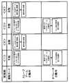
- the operation sequence information 51is a task program that defines the operation of the slave arm 1 and includes information related to the operation sequence that defines the processing of each step performed by the slave arm 1 in the work space. Specifically, in the robot system 100 according to the present embodiment, as shown in FIG. 3, information is obtained by associating the operation order, the operation mode of the slave arm 1, and the operation flow of each process.
- FIG. 3is a diagram illustrating an example of an operation sequence of the robot system 100 according to Example 1 of the embodiment of the invention.
- the storage device 6may store scheduled trajectory information (not shown) indicating the planned trajectory range of the slave arm 1.
- scheduled trajectory informationinclude time-series information such as the position and posture of the slave arm 1 scheduled for performing each step of a series of operations.
- the planned trajectory informationis stored in the storage device 6, it can be used to detect whether or not the slave arm 1 has deviated from the planned trajectory range.
- the storage device 6is provided separately from the control device 3, but may be provided integrally with the control device 3.
- the master device 9is an input device that is installed outside the work space and receives an operation instruction from an operator, and includes a master arm 2 and an operation instruction unit 7.
- the slave arm 1moves following the movement of the master arm 2. Since the master arm 2 has a similar structure to the slave arm 1, a description of the configuration of the master arm 2 is omitted.
- the master arm 2may be an input device (joystick) having a structure similar to that of the slave arm 1 and capable of inputting a direction by a lever, for example.
- the operation instruction unit 7is an input device that is installed outside the work space like the master arm 2, receives an operation instruction from an operator, and transmits the received operation instruction to the control device 3 of the slave arm 1 as an operation input signal.
- Examples of the operation instruction unit 7include an input switch for receiving an operation instruction from an operator, or a portable terminal such as a tablet.
- the operation input signal transmitted from the master device 9 to the control device 3 of the slave arm 1is input from the operator via the operation instruction unit 7 in addition to the signal input from the operator via the master arm 2.
- a signalmay be included.
- FIG. 4is a diagram schematically illustrating an example of the slave arm 1 that performs work along the operation sequence illustrated in FIG. 3.
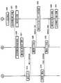
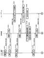
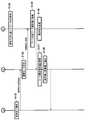
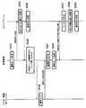
- 5 and 6are flowcharts showing an example of operation processing in each of the master device 9, the control device 3, and the slave arm 1 that implements the operation sequence shown in FIG.
- the operation sequence of the robot system 100is described by taking as an example the work of assembling a work on an object to be assembled.
- the entire operation sequence shown in FIG. 3is referred to as work, and each process indicated by ⁇ 1> to ⁇ 5> in FIG. 3 is referred to as a process.
- the process implemented by each processis called a step.
- ⁇ 1> to ⁇ 5> in FIG. 3indicate the execution order of each process in the work.
- the slave arm 1is configured to operate in accordance with the above-described operation sequence by executing the operation sequence information 51 as a task program in the robot system 100.
- the slave arm 1performs the movement from the position where the workpiece is stored to the vicinity of the assembly position of the workpiece (assembly preparation position) in the automatic mode.
- the assembly preparation positionWhen the slave arm 1 brings the workpiece to the assembly preparation position, the assembly of the workpiece to the assembly target is complicated because the positioning of the assembly position and the assembly work are complicated.
- the slave arm 1is designed to perform in the manual mode.
- This operation sequence relating to the work of the first embodimentcan be applied as an automobile outfitting process in which the assembly target is a vehicle body, the work A is a front seat, and the work B is a rear seat. Further, the present invention can be applied to an assembly process of a robot in which an object to be assembled is an arm, a work A is a reduction gear, and a work B is a motor.
- the work assembly work to deal with the assemblyis taken as an example, and the first to fourth embodiments will be described below, but the work performed using the robot system 100 is limited to this. is not.
- itmay be a painting operation on a workpiece.
- this painting workinclude a painting work in which the slave arm 1 paints a work conveyed to a painting area (not shown) by a conveyor device (not shown). Or the painting operation
- the operatoroperates the operation instruction unit 7 of the master device 9 to input a start instruction (step S11). That is, a start instruction signal for instructing the start of an operation sequence is transmitted from the master device 9 to the control device 3 as an operation input signal.
- the receiving unit 40is in a standby state for an operation input signal (start instruction signal), and when the receiving unit 40 receives the start instruction signal, the operation control unit 41 determines the operation mode of the slave arm 1. (Step S21).
- the operation control unit 41may be configured to determine the operation mode of the slave arm 1 with reference to the operation sequence information 51 stored in the storage device 6. Alternatively, the operation control unit 41 may include information on the operation mode of the slave arm 1 in the next step included in the start instruction signal transmitted from the master device 9 and performed based on the information.
- the operation control unit 41determines the operation mode as follows. That is, in the operation sequence information 51, the operation mode of the slave arm 1 is set to the automatic mode in the operation order ⁇ 1> that is the first step. Therefore, the operation control unit 41 determines that the operation mode of the slave arm 1 is the automatic mode, and controls the slave arm 1 to operate in the automatic mode. That is, the operation control unit 41 refers to the operation sequence information 51 and transmits a control instruction to the slave arm 1 so that the slave arm 1 performs each step of the operation order ⁇ 1>.
- the slave arm 1moves to the work A take-out position and takes out the work A (step S31).
- the positional relationship among the workpiece A, the assembly target, and the slave arm 1 at this timeis in the state shown in FIG.
- the slave arm 1moves to the assembly preparation position while holding the workpiece A as shown in FIG. 4B (step S32).
- the slave arm 1enters an operation instruction signal waiting state (operation waiting state) (step S33).
- the operation instruction signalis an operation input signal transmitted to the slave arm 1 via the master device 9 (master arm 2) when the slave arm 1 is operated in the manual mode by the operator.
- the operation control unit 41can determine whether or not the slave arm 1 has reached the assembly preparation position based on the situation information acquired from the situation information acquisition unit 5.
- a dashed arrow extending from the subsequent stage of step S ⁇ b> 32 of the slave arm 1 to the previous stage of step S ⁇ b> 22 of the control device 3represents acquisition of status information by the control device 3.
- the operation control unit 41When the operation control unit 41 confirms that the slave arm 1 has reached the assembly preparation position (step S22), the operation control unit 41 notifies the output control unit 42 to notify the operator that the preparation for the assembly operation has been completed. Instruct.
- the output control unit 42controls the output device 4 in accordance with an instruction from the operation control unit 41 to output information indicating completion of assembly work preparation (step S23).
- the receiving unit 40is in a standby state for an operation input signal transmitted as an input signal from the master device 9.
- a broken-line arrowextending from the subsequent stage of step S ⁇ b> 23 of the control apparatus 3 to the previous stage of step S ⁇ b> 12 of the master apparatus 9 represents detection of a preparation completion notification by the operator.
- the operatorWhen the output device 4 is notified of the completion of preparation, the operator inputs an operation mode switching instruction from the operation instruction unit 7 of the master device 9, and then performs an operation input using the master arm 2 of the master device 9 ( Step S12). As a result of these inputs, an operation mode switching signal from the operation instruction unit 7 and an operation input signal from the master arm 2 are transmitted to the control device 3, respectively.
- the operation control unit 41determines the operation mode of the slave arm 1 (step S24). Since the operation mode is the manual mode in the operation order ⁇ 2> of the next process, the operation control unit 41 transmits a control instruction based on the operation input signal input via the master arm 2 to the slave arm 1.
- the slave arm 1operates following the operation of the master arm 2. Specifically, the slave arm 1 assembles the workpiece A to the assembly target as shown in FIG. 4C according to the operation input signal input via the master arm 2 (step S34). ). When the assembly of the workpiece A is completed with respect to the assembly target, the operator operates the operation instruction unit 7 of the master device 9 to input a work completion notification (step S13). A work completion signal is transmitted from the master device 9 to the control device 3 in response to the input of the work completion notification.
- the operation control unit 41determines the operation mode of the slave arm 1 in the next step (step S25).
- the operation control unit 41may be configured to determine the operation mode of the slave arm 1 with reference to the operation sequence information 51 stored in the storage device 6.
- the operation control unit 41may include information on the operation mode of the slave arm 1 in the next step included in the work completion signal transmitted from the master device 9 and performed based on the information.
- the operation control unit 41determines that the operation mode is the automatic mode, refers to the operation sequence information 51, and issues a control instruction so that the slave arm 1 performs each step of the operation order ⁇ 3>. Send to arm 1
- the slave arm 1retreats from the assembly completion position of the workpiece A in response to a control instruction from the operation control unit 41 (step S35). Then, as shown in FIG. 4D, the slave arm 1 takes out the workpiece B (step S36). When the workpiece B is taken out, the slave arm 1 moves to the assembly preparation position while holding the workpiece B as shown in FIG. 4E (step S37). When the slave arm 1 moves to the assembly preparation position, the slave arm 1 enters a standby state for an operation instruction signal (step S38).
- the operation control unit 41may determine whether or not the slave arm 1 has reached the assembly preparation position based on the situation information acquired from the situation information acquisition unit 5 as in step S32.
- a dashed arrow extending from the subsequent stage of step S ⁇ b> 37 of the slave arm 1 toward the previous stage of step S ⁇ b> 26 of the control device 3represents acquisition of status information by the control device 3.
- the operation control unit 41When the operation control unit 41 confirms that the slave arm 1 has reached the assembly preparation position (step S26), the operation control unit 41 notifies the output control unit 42 that the preparation for the assembly operation has been completed. To instruct.
- the output control unit 42controls the output device 4 to output information indicating completion of preparation for assembly work (step S27). Thereafter, the receiving unit 40 enters a standby state for an operation input signal transmitted from the master device 9.
- the dashed arrow extending from the subsequent stage of step S ⁇ b> 27 of the control apparatus 3 to the previous stage of step S ⁇ b> 14 of the master apparatus 9indicates that the operator has detected the preparation completion notification output from the output apparatus 4. Represents.
- the operatorWhen the output device 4 is notified of the completion of assembly work preparation for the workpiece B, the operator performs an operation input together with an operation mode change instruction using the master arm 2 and the operation instruction unit 7 of the master device 9 (step S14). .
- the operation mode change instruction and the operation input input via the master device 9are transmitted to the control device 3 as an operation mode switching signal and an operation input signal.
- the operation control unit 41determines the operation mode of the slave arm 1 in the next step (step S28). In the example of the operation sequence information 51 shown in FIG. 3, the operation mode is set to the manual mode in the next operation order ⁇ 4>.
- the operation control unit 41determines that the operation mode is the manual mode, and transmits a control instruction (manual mode) based on the operation input signal received from the master arm 2 to the slave arm 1.
- the slave arm 1operates following the operation of the master arm 2.
- the slave arm 1assembles the workpiece B on the assembly target as shown in FIG. 4 (f) in accordance with the operation input from the master arm 2 (step S39).
- the operatoroperates the operation instruction unit 7 of the master device 9 to input a work completion notification (step S15). Then, the work completion notification input by the operation instruction unit 7 is transmitted to the control device 3.
- the operation control unit 41determines the operation mode of the slave arm 1 in the next process (step S29).
- the operation modeis set to the automatic mode in the operation order ⁇ 5>. Therefore, the operation control unit 41 determines that the operation mode is the automatic mode, and controls the slave arm 1 to automatically perform each step of the operation order ⁇ 5> that is the next process.
- the slave arm 1retreats from the assembly completion position of the workpiece A in response to a control instruction (automatic mode) from the operation control unit 41 (step S40). Then, the slave arm 1 moves to the entire work completion position (step S41).
- the robot system 100performs an operation sequence related to work including a series of steps.
- the slave arm 1performs the rough operation in the automatic mode, and the detailed operation or the like is performed manually according to the operation input from the operator. This can be done depending on the mode.
- the determination of the operation mode by the operation control unit 41is based on the operation sequence information triggered by the reception unit 40 receiving the start instruction signal, the operation input signal, or the work completion signal transmitted from the master device 9.
- the determinationmay be made with reference to 51.
- the start instruction signal, the operation input signal, or the work completion signalincludes information indicating the operation mode to be executed in the next process, and the operation mode included in these signals transmitted from the master device 9 is displayed.
- the operation control unit 41may determine the operation mode based on the information shown. In the case where the operation control unit 41 determines the operation mode based on the signal transmitted from the master device 9, the operation sequence information 51 stored in the storage device 6 does not need to include information related to the operation mode.
- the above-described operation sequenceis a sequence example assuming that the control device 3 can recognize the external environment with respect to the environment surrounding the slave arm 1 at the start of the work of the slave arm 1.
- the controller 3cannot recognize the outside world with respect to the environment surrounding the slave arm 1.
- the slave arm 1may be moved to a position where the controller 3 can recognize the outside world in the manual mode, and then the operation sequence may be switched from the manual mode to the automatic mode.
- an operation sequence in the case where the control device 3 cannot recognize the outside world with respect to the environment surrounding the slave arm 1 at the time of disclosing the work of the slave arm 1will be described as a second embodiment.
- FIG. 7is a diagram showing an example of an operation sequence of the robot system 100 according to Example 2 of the embodiment of the present invention.
- FIG. 8is a diagram schematically illustrating an example of the slave arm 1 that performs work along the operation sequence illustrated in FIG. 7.
- FIGS. 9 and 10are flowcharts showing an example of operation processing in each of the master device 9, the control device 3, and the slave arm 1 that performs the operation sequence shown in FIG.
- the operation sequence of the robot system 100is described by taking as an example the operation of grasping a predetermined work and moving it to a work place in an environment where a plurality of works are mixed in the work space.
- the operation order ⁇ 1> to ⁇ 4> in FIG. 7indicate the operation order in the operation sequence.
- the slave arm 1performs gripping of a predetermined workpiece from the mixed workpieces by manual operation according to an instruction from the operator.
- the slave arm 1performs the movement to the work place by automatic operation.
- This operation sequence related to a work consisting of a series of stepscan be applied as a moving work for moving a large workpiece such as a slag or a casting having a non-uniform dimension present in a work environment having a bad environment to a predetermined position.
- the operatoroperates the master device 9 to input a start instruction (step S111).
- a start instruction signal instructing the start of the operation sequenceis transmitted from the master device 9 to the control device 3.
- the receiving unit 40is in a standby state for an operation input signal (start instruction signal). Then, when a start instruction signal is transmitted from the master device 9 to the control device 3, the reception unit 40 receives the start instruction signal.
- the operation control unit 41determines the operation mode of the slave arm 1 (step S121). In the operation order ⁇ 1> which is the first step, the operation mode is set to the manual mode. For this reason, the operation control unit 41 determines that the operation mode is the manual mode. Thereafter, the operator inputs an operation using the master arm 2 of the master device 9 (step S112). An operation input by the operator is transmitted to the control device 3 as an operation input signal via the master arm 2 of the master device 9. The control device 3 transmits a control instruction based on the operation input signal received from the master arm 2 to the slave arm 1. As a result, the slave arm 1 operates following the operation of the master device 9.
- the slave arm 1grips the workpiece A as shown in FIG. 8A according to the operation input from the master device 9 (step S131).
- the operatorinputs a gripping completion notification via the operation instruction unit 7 of the master device 9 (step S113).
- a grip completion signalis transmitted from the master device 9 to the control device 3 in response to the grip completion notification input.
- the operation control unit 41determines the operation mode of the slave arm 1 (step S122).
- the operation modeis set to the automatic mode in the operation order ⁇ 2> that is the next process. Therefore, the operation control unit 41 determines that the operation mode is the automatic mode, refers to the operation sequence information 51, and controls the slave arm 1 to automatically perform each step of the operation order ⁇ 2>. To do.
- the slave arm 1moves to the work place while holding the work A as shown in FIG. 8B (step S132). Then, the slave arm 1 places the gripped work A on the work place and enters a standby state for an operation instruction signal (step S133).
- the operation control unit 41can determine whether or not the slave arm 1 has reached the work place based on the situation information acquired from the situation information acquisition unit 5.
- a dashed arrow extending from the subsequent stage of step S ⁇ b> 132 of the slave arm 1 toward the previous stage of step S ⁇ b> 123 of the control device 3represents acquisition of status information by the control device 3.
- the operation control unit 41When the operation control unit 41 confirms that the slave arm 1 has reached the work place (step S123), the operation control unit 41 instructs the output control unit 42 to notify the operator that the movement of the work A has been completed. To do.
- the output control unit 42controls the output device 4 in accordance with an instruction from the operation control unit 41 to output information indicating the completion of movement of the workpiece A (step S124).
- a broken-line arrow extending from the subsequent stage of step S124 of the control device 3 to the previous stage of step S114 of the master apparatus 9represents detection of a preparation completion notification by the operator.
- the operatorWhen the completion of movement is notified in the output device 4, the operator inputs an operation mode switching instruction via the operation instruction unit 7 of the master device 9, and inputs an operation using the master arm 2 (step S114). As a result of these inputs, an operation mode switching signal from the operation instruction unit 7 and an operation input signal from the master arm 2 are transmitted to the control device 3, respectively.
- the operation control unit 41determines the operation mode of the slave arm 1 in the next process (step S125). In the example of the operation sequence information 51 shown in FIG. 7, the operation mode is set to the manual mode in the next operation order ⁇ 3>. Therefore, the operation control unit 41 determines that the operation mode is the manual mode, and transmits a control instruction (manual mode) based on the operation input signal received from the master arm 2 to the slave arm 1.
- the slave arm 1grips the workpiece B as shown in FIG. 8C in accordance with the operation input from the master arm 2 (step S134).
- the operatoroperates the operation instruction unit 7 of the master device 9 and inputs a gripping completion notification (step S115).
- a grip completion signalis transmitted from the master device 9 to the control device 3 in response to a grip completion notification input.
- the operation control unit 41determines the operation mode of the slave arm 1 in the next process (step S126).
- the operation control unit 41may be configured to determine the operation mode of the slave arm 1 with reference to the operation sequence information 51 stored in the storage device 6.
- the motion control unit 41may be configured to include information on the operation mode of the slave arm 1 in the next step in the grip completion signal transmitted from the master device 9 and to perform based on the information.
- the operation modeis set to the automatic mode in the operation order ⁇ 4>. Therefore, the operation control unit 41 determines that the operation mode is the automatic mode, and controls the slave arm 1 to automatically execute each step of the operation order ⁇ 4> as the next process.
- the slave arm 1moves to the work place while holding the work B as shown in FIG. 8D (step S135). Then, the slave arm 1 places the gripped work A on the work place, and enters an operation instruction signal waiting state (step S136).
- the operation control unit 41may determine whether or not the slave arm 1 has reached the work place based on the situation information acquired from the situation information acquisition unit 5 as in step S132.
- step S127When the operation control unit 41 confirms that the slave arm 1 has reached the work place (step S127), the operation control unit 41 notifies the output control unit 42 that the movement of the work A has been completed. Instruct.
- the output control unit 42controls the output device 4 to output information indicating the completion of movement of the workpiece B (step S128).
- a broken-line arrow extending from the subsequent stage of step S135 of the slave arm 1 to the previous stage of step S127 of the control device 3represents acquisition of status information by the control device 3.
- a broken-line arrow extending from the subsequent stage of step S128 of the control apparatus 3 toward the master apparatus 9indicates that the operator has detected a movement completion notification output from the output apparatus 4.
- the operation mode determination by the operation control unit 41 described aboveis triggered by reception of an operation input signal (a start instruction signal, a grip completion signal or the like) transmitted from the master device 9 by the reception unit 40 as a trigger. You may determine with reference to. Alternatively, information indicating an operation mode to be performed in the next process is included in the operation input signal (such as a start instruction signal or a grip completion signal), and the operation control unit 41 is based on the signals transmitted from the master device 9. The operation mode may be determined. In the case where the operation control unit 41 determines the operation mode based on the signal transmitted from the master device 9, the operation sequence information 51 stored in the storage device 6 does not need to include information related to the operation mode.
- an operation input signala start instruction signal, a grip completion signal or the like
- Example 3(Continuation permission judgment / operation mode judgment]
- the operation control unit 41determines that the operation mode is the automatic mode
- all the steps included in the processare configured so that the slave arm 1 operates in the automatic mode. there were.
- the present inventionis not limited to this configuration. Whether the operation of the slave arm 1 is permitted to continue in the automatic mode according to the work status of the slave arm 1 or the like even in the process determined to be the automatic mode. It is good also as a structure which can determine whether or not and can change an operation mode from an automatic mode as needed.
- the slave arm 1when the slave arm 1 is retracted from the assembly completion position in the automatic mode in step S35 shown in FIG. 5, the slave arm 1 continues to perform the next step S36 shown in FIG. 6 in the automatic mode. Instead, it may be configured to determine whether or not the operation in step S36 may be continued in the automatic mode. In other words, the slave arm 1 may operate in the automatic mode until step S35, and it may be configured to determine whether the automatic mode can be continued for the steps after step S36. Note that the timing for determining whether or not to continue the automatic mode is not limited to that after step S35 described above.
- the automatic mode continuation permission determination timingis preferably based on the content of the step executed by the slave arm 1 at a position before the predetermined step is executed.
- the slave arm 1is scheduled to operate in the automatic mode, for example, the slave arm 1 is applied to the workpiece in the automatic mode. It can be a process that is scheduled to be applied.
- the automatic mode continuation permission determination timingcan be set, for example, when the slave arm 1 paints to a predetermined position on the painting surface in the automatic mode.
- the step to be subjected to the automatic mode continuation permission determinationis a coating step performed by the slave arm 1 on the coating surface after the predetermined position.
- FIG. 11is a flowchart showing an example of an operation sequence of the robot system according to Example 3 of the embodiment of the present invention.
- the operation of the robot system according to the third embodimentwill be described by taking a plurality of steps included in the process of the operation order ⁇ 3> shown in FIG. Therefore, steps S235 and S237 to S239 performed by the slave arm 1 in FIG. 11 correspond to steps S35 to S38 performed by the slave arm 1 in FIGS. Further, step S225 performed by the control device 3 in FIG. 11 corresponds to step S25 performed by the control device 3 in FIG. Therefore, detailed description of these steps is omitted.
- step S225the operation control unit 41 of the control device 3 determines the operation mode for the process that the slave arm 1 is to perform next.
- the operation modeis set to the automatic mode in the operation order ⁇ 3> of the next process. Therefore, the operation control unit 41 determines that the operation mode is the automatic mode. Then, the operation control unit 41 transmits the control instruction (automatic mode) to the slave arm 1 to control the slave arm 1 so that each step of the operation order ⁇ 3> is performed in the automatic mode. Then, according to the control instruction from the operation control unit 41, the slave arm 1 automatically retracts from the assembly completion position of the workpiece A (step S235).
- the operation control unit 41detects that the slave arm 1 has retreated from the assembly completion position and moved to a predetermined position. After this detection, the operation control unit 41 instructs the output control unit 42 to make an inquiry about whether or not to permit the continuation of the automatic mode. In response to the instruction from the operation control unit 41, the output control unit 42 controls the output device 4 to output an inquiry as to whether or not the continuation of the automatic mode is permitted (step S226). At this time, the operation control unit 41 temporarily stops the operation of the slave arm 1 in the automatic mode, and waits for an operation waiting state (step S236).
- the receiving unit 40 of the control device 3is in a standby state for an operation input signal transmitted from the master device 9.
- a broken-line arrow extending from the subsequent stage of step S235 of the slave arm 1 to the previous stage of step S236 of the control device 3is used to confirm that the slave arm 1 has moved to a predetermined position. It represents that the control device 3 receives the status information.
- the dashed arrow extending from the subsequent stage of step S226 of the control apparatus 3 to the previous stage of step S210 of the master apparatus 9indicates that the operator has detected an inquiry as to whether or not to continue the automatic mode. Represents what to do.
- the operatorWhen an inquiry about whether or not to permit the continuation of the automatic mode is notified by the output device 4, the operator operates the operation instruction unit 7 of the master device 9 to determine whether or not to permit the continuation of the automatic mode. Is input (step S210).
- the instruction information input via the operation instruction unit 7is transmitted to the control device 3 as an operation input signal.
- the continuation determining unit 46determines whether or not the continuation of the operation of the slave arm 1 in the automatic mode is permitted (step S227).
- the continuation determination unit 46notifies the operation control unit 41 of the determination result.
- the operation control unit 41determines the operation mode of the slave arm 1 based on the determination result notified from the continuation determination unit 46 (step S228), and controls the slave arm 1 to operate in the determined operation mode. For example, when the determination result notified from the continuation determination unit 46 permits the continuation of the automatic mode, the operation control unit 41 keeps the operation mode of the slave arm 1 in the automatic mode and sends a control instruction to the slave mode. It transmits to the arm 1 and it controls so that it may operate
- the operation control unit 41sets the operation mode of the slave arm 1 to the manual mode or the corrected automatic mode. It is determined that the mode.
- the operation control unit 41sets the slave arm 1 to operate in the manual mode according to the operation input signal from the master arm 2 received by the receiving unit 40. Control.
- the operation control unit 41operates by correcting a part of the operation of the slave arm 1 in the automatic mode by the operation input signal from the master arm 2. The slave arm 1 is controlled.
- the slave arm 1automatically takes out the workpiece B (step S237) and moves to the assembly preparation position (step S238). ) Is performed, and an operation waiting state for the next process is entered (step S239).
- the slave arm 1takes out the workpiece B in the manual mode or the correction automatic mode, for example (step S237), and prepares for assembly. The movement to the position (step S238) is performed, and the operation waiting state (step S239) for the next process is entered.
- the slave arm 1does not perform steps S237 to S239 and remains in a stopped state. Also good.
- the operatoris inquired as to whether or not the continuation of the automatic mode is permitted, and the continuation determination unit 46 determines whether or not the automatic mode can be continued based on the operation input signal input via the operation instruction unit 7 of the master device 9.
- the continuation determination unit 46may determine whether or not the automatic mode can be continued based on the situation information acquired by the situation information acquisition unit 5 without inquiring of the operator as to whether or not to continue the automatic mode. .
- the continuation determination unit 46can determine whether to permit the continuation of the automatic mode before executing a predetermined step according to the progress of each step in the process performed by the slave arm 1. . More specifically, it is assumed that the robot system 100 includes a measuring unit that measures the completion time of each step performed by the slave arm 1 as the situation information acquisition unit 5. Then, before carrying out a predetermined step (take out work B in the example of FIG. 11), the time before the step (retracted from the assembly position in the example of FIG. 11) is completed, and the scheduled time The completion time of the previous step (standard time taken to process the previous step) is compared, and if a deviation of a predetermined range or more has occurred, the continuation determination unit 46 does not permit the continuation of the automatic mode. judge.
- the continuation determination unit 46may be configured to permit the continuation of the automatic mode.
- step S226 performed by the control device 3 and step S210 performed by the master device 9 in FIG. 11can be omitted.
- the continuation determination unit 46permits the continuation of the automatic mode based on the result detected by the sensor. It can also be configured to determine whether or not to do so. More specifically, based on the detection result of the above-described sensor, it is determined in step S235 whether or not the slave arm 1 has been retracted within a predetermined range. When it is determined that the slave arm 1 is not retracted within the predetermined range, the continuation determination unit 46 does not permit the continuation of the automatic mode. On the other hand, when it is determined that the slave arm 1 is within the predetermined range, the continuation determination unit 46 may be configured to permit the continuation of the automatic mode.
- the robot system 100 according to the third embodimenthas a configuration in which the control device 3 inquires of the operator whether to permit the continuation of the automatic mode in step S226 shown in FIG. 11 and determines the operation mode in step S227.
- the operation control unit 41determines the operation mode of the slave arm 1 based on the input from the operator in response to this inquiry, and controls the slave arm 1 to operate according to the determined operation mode.
- FIG. 12is a flowchart illustrating an example of an operation sequence of the robot system 100 according to the fourth example of the embodiment of the present invention.
- step S328the operation sequence of the robot system 100 according to the fourth embodiment is compared with the operation sequence of the robot system 100 according to the third embodiment shown in FIG. It is the same except that a step (step S328) and a step (step S311) in which the master device 9 (operator) performs mode designation input in response to this inquiry are further added. Therefore, in FIG. 12, only step S328 in the operation flow of the control device 3 and step S311 in the operation flow of the master device 9 will be described, and description of other steps will be omitted.
- step S327when the continuation determination unit 46 of the control device 3 determines that the continuation of the automatic mode is not permitted, the operation control unit 41 inquires of the operator about the operation mode in which the slave arm 1 operates in the subsequent steps. This is performed (step S328). More specifically, the operation control unit 41 instructs the output control unit 42 to make an inquiry about the operation mode of the slave arm 1. In response to the instruction from the operation control unit 41, the output control unit 42 controls the output device 4 to output an operation mode inquiry (operation mode inquiry information) (step S328). At this time, the receiving unit 40 of the control device 3 is in a standby state for an operation input signal (mode designation input signal) transmitted from the master device 9.
- mode designation input signalmode designation input signal
- a broken-line arrow extending from the subsequent stage of step S328 of the control apparatus 3 to the previous stage of step S311 of the master apparatus 9indicates that the operator detects an inquiry about the operation mode.
- the operatorWhen the output device 4 is notified of the inquiry about the operation mode, the operator performs mode designation input via the operation instruction unit 7 of the master device 9 (step S311).
- the mode designation input by the operation instruction unit 7is transmitted to the control device 3 as a mode designation input signal.
- the operation control unit 41determines the operation mode of the slave arm 1 (step S329). Then, the operation control unit 41 controls the slave arm 1 so as to operate in the determined operation mode.
- the mode of operation mode inquiry by the output device 4is preferably selected as appropriate in accordance with the operator's work environment and the work content performed by the operator. For example, when the output device 4 is a speaker, the operator may be notified of the operation mode inquiry by sound. When the output device 4 is a light, an operation mode inquiry may be made to the operator with light. Alternatively, when the output device 4 is a vibration generating device, the operation mode may be inquired to the operator by vibration.
- the robot system 100can be widely applied to systems having an automatic mode, a manual mode, and a correction automatic mode as slave arm operation modes.
Landscapes
- Engineering & Computer Science (AREA)
- Robotics (AREA)
- Mechanical Engineering (AREA)
- Health & Medical Sciences (AREA)
- Life Sciences & Earth Sciences (AREA)
- Surgery (AREA)
- Human Computer Interaction (AREA)
- Physics & Mathematics (AREA)
- Automation & Control Theory (AREA)
- General Health & Medical Sciences (AREA)
- General Physics & Mathematics (AREA)
- Public Health (AREA)
- Nuclear Medicine, Radiotherapy & Molecular Imaging (AREA)
- Veterinary Medicine (AREA)
- Biomedical Technology (AREA)
- Heart & Thoracic Surgery (AREA)
- Medical Informatics (AREA)
- Molecular Biology (AREA)
- Animal Behavior & Ethology (AREA)
- Theoretical Computer Science (AREA)
- Multimedia (AREA)
- General Engineering & Computer Science (AREA)
- Computer Vision & Pattern Recognition (AREA)
- Signal Processing (AREA)
- Quality & Reliability (AREA)
- Manufacturing & Machinery (AREA)
- Computer Networks & Wireless Communication (AREA)
- Mathematical Physics (AREA)
- Fuzzy Systems (AREA)
- Evolutionary Computation (AREA)
- Software Systems (AREA)
- Artificial Intelligence (AREA)
- Orthopedic Medicine & Surgery (AREA)
- Geometry (AREA)
- Manipulator (AREA)
- Numerical Control (AREA)
- Force Measurement Appropriate To Specific Purposes (AREA)
- Control Of Position Or Direction (AREA)
- Automatic Assembly (AREA)
Abstract
Description
Translated fromJapanese本発明は、マスタースレーブ方式ロボットを利用したロボットシステムに関する。The present invention relates to a robot system using a master-slave robot.
作業を自動化し、省人化または作業の効率化を図るために産業用ロボットの開発が進められている。産業用ロボットは、例えば、組付部品(ワーク)の搬送・組付などを行うロボットとして工場等に設置される。ここで組付部品の組付をロボットに自動で実施させる場合、組付部品および被組付部品(製品)それぞれの位置関係をセンサにより計測し、精度よくロボットの位置と姿勢を合わせる機構および制御が必要となる。特に、組付部品または被組付部品が大型部品であって、自動でロボットによりこの組付部品の組付作業を実施させる場合、ロボットと組付部品との位置関係または組付部品と被組付部品との位置関係を正確に把握できるようにするためには、多数のセンサが必要となる。さらには、広範な作業空間内で高精度な計測を可能とする高度なセンサ認識技術も要求される。このため、組付部品または被組付部品が大型部品となる場合であって、自動でロボットにより組付作業を実施させるとき、コストが増大するとともに、少しでも作業環境等に変化が生じると高精度な計測結果が得られず組付作業に誤差、もしくは、不用意な干渉を生じる。Developed industrial robots to automate work and save labor or improve work efficiency. The industrial robot is installed in a factory or the like as a robot that carries, for example, an assembly part (workpiece). Here, when the assembly parts are automatically assembled by the robot, a mechanism and control for accurately measuring the positional relationship between the assembled parts and the parts to be assembled (products) with the sensors and aligning the robot position and posture with high accuracy. Is required. In particular, when the assembly part or the part to be assembled is a large part and the assembly work of this assembly part is automatically performed by the robot, the positional relationship between the robot and the assembly part or the assembly part and the assembly part In order to be able to accurately grasp the positional relationship with the attached part, a large number of sensors are required. Furthermore, an advanced sensor recognition technology that enables highly accurate measurement in a wide work space is also required. For this reason, when the assembly part or the part to be assembled is a large part, and when the assembly work is automatically performed by the robot, the cost increases and a slight change in the work environment is required. Accurate measurement results cannot be obtained, resulting in errors in assembly work or inadvertent interference.
そこで、自動でロボットに作業をさせているときに作業環境等に変化が生じた場合、オペレータからの操作指示に基づきロボットを動作させる手動運転に切り替えることができる遠隔操作制御装置が提案されている(特許文献1)。特許文献1に係る遠隔操作制御装置は、ロボットの自動運転の基礎となる環境モデルが実際の作業環境と一定以上ずれている場合に、それを検出して自動運転から手動運転に切り替えることができる。In view of this, there has been proposed a remote operation control device capable of switching to manual operation for operating a robot based on an operation instruction from an operator when a change occurs in a work environment or the like when the robot is automatically operated. (Patent Document 1). The remote operation control device according to
本発明は、自動モードによりスレーブアームが動作する予定の工程においてスレーブアームを適切に動作させることができるロボットシステムを提供することを目的とする。The present invention has an object of providing a robot system capable of appropriately operating a slave arm in a process in which the slave arm is scheduled to operate in an automatic mode.
本発明のある形態に係るロボットシステムは、上記した課題を解決するために、オペレータからの操作指示を受けつけるマスター装置と、複数のステップを含む工程において、該ステップの処理を実施するスレーブアームと、前記スレーブアームによって実施される前記処理を規定した動作シーケンス情報を記憶する記憶装置と、前記スレーブアームの動作を制御する制御装置と、を備え、前記制御装置は、入力信号を受信する受信部と、前記スレーブアームの運転モードを、前記動作シーケンス情報に基づき動作させる自動モードとするか、前記マスター装置を介して入力された操作指示に基づき動作させる手動モードとするか、あるいは、該自動モードで動作中のスレーブアームの動作を、該マスター装置を介して入力された操作指示に基づき修正する修正自動モードとするか判定し、判定した運転モードにより前記スレーブアームの動作を制御する動作制御部と、前記自動モードの継続を許可するか否か判定する継続判定部と、を有し、前記自動モードにより前記スレーブアームが動作する予定の工程において、前記動作制御部によって、該工程の所定のステップで該自動モードによるスレーブアームの動作を停止させた後、前記継続判定部は、該動作の停止時に前記受信部により受信した入力信号に基づき、該自動モードの継続を許可するか否か判定する。In order to solve the above-described problem, a robot system according to an aspect of the present invention includes a master device that receives an operation instruction from an operator, a slave arm that performs processing of the step in a process including a plurality of steps, A storage device that stores operation sequence information that defines the processing performed by the slave arm; and a control device that controls the operation of the slave arm; and the control device includes a receiving unit that receives an input signal; The operation mode of the slave arm is an automatic mode that operates based on the operation sequence information, a manual mode that operates based on an operation instruction input via the master device, or the automatic mode Operation instruction input via the master device to indicate the operation of the slave arm during operation Based on the determined operation mode, and an operation control unit that controls the operation of the slave arm, and a continuation determination unit that determines whether or not to permit the continuation of the automatic mode. In the process where the slave arm is scheduled to operate in the automatic mode, after the operation control unit stops the operation of the slave arm in the automatic mode in a predetermined step of the process, the continuation determining unit is It is determined whether to permit the continuation of the automatic mode based on the input signal received by the receiving unit when the operation is stopped.
上記構成によるとマスター装置とスレーブアームとを備えているため、オペレータからマスター装置を介してスレーブアームに操作指示を送信し、一連の作業を実施させることができる。According to the above configuration, since the master device and the slave arm are provided, an operation instruction can be transmitted from the operator to the slave arm via the master device, and a series of operations can be performed.
また、制御装置は、動作制御部を有しているため、スレーブアームを自動モード、手動モード、および修正自動モードのうちのいずれの運転モードとするか判定して、適切な運転モードによりスレーブアームを動作させるように制御することができる。In addition, since the control device has an operation control unit, it is determined whether the slave arm is set to the automatic mode, the manual mode, or the correction automatic mode, and the slave arm is operated according to an appropriate operation mode. Can be controlled to operate.
また、制御装置が継続判定部を有しているため、自動モードによりスレーブアームが動作する予定の工程において、該工程の所定のステップで、自動モードの継続を許可するか否か判定することができる。このため、例えば、このまま自動モードを継続すると予定された時間までに工程の全ステップを完了させることができない場合、あるいは次のステップ以降に行う処理を自動モードでは精度よく行うことができない場合などでは、スレーブアームの運転モードを手動または修正自動モードなど他のモードに変えて処理を続けることができる。また、同じ製造ラインにおいて多品種の製品を組み立てる場合、品番によっては自動モードで組み立てることが困難なときも、スレーブアームの運転モードを手動または修正自動モードなど他のモードに変えて処理を続けることができる。In addition, since the control device has a continuation determination unit, it is possible to determine whether or not to permit the continuation of the automatic mode in a predetermined step of the process in a process in which the slave arm is scheduled to operate in the automatic mode. it can. For this reason, for example, when it is not possible to complete all steps of the process by the scheduled time to continue the automatic mode as it is, or when the processing to be performed after the next step cannot be accurately performed in the automatic mode The operation can be continued by changing the operation mode of the slave arm to another mode such as a manual mode or a correction automatic mode. Also, when assembling a wide variety of products on the same production line, depending on the part number, even if it is difficult to assemble in automatic mode, continue processing by changing the slave arm operation mode to another mode such as manual or modified automatic mode Can do.
逆に、自動モードによるスレーブアームの動作によって適切に処理がなされている場合では、そのまま自動モードとしスレーブアームの動作を継続させることができる。Conversely, if the processing is appropriately performed by the operation of the slave arm in the automatic mode, the operation of the slave arm can be continued as it is in the automatic mode.
したがって、本発明に係るロボットシステムは、自動モードによりスレーブアームが動作する予定の工程においてスレーブアームを適切に動作させることができるという効果を奏する。Therefore, the robot system according to the present invention has an effect that the slave arm can be appropriately operated in the process in which the slave arm is scheduled to operate in the automatic mode.
本発明のある形態に係るロボットシステムは、上記した構成において、前記オペレータに通知すべき情報を出力する出力装置を備え、前記動作制御部により、前記所定のステップで前記自動モードによる前記スレーブアームの動作が停止させられた後、前記出力装置は、前記オペレータに通知すべき情報として、該自動モードの継続を許可するか否かについての問い合わせを出力しており、前記継続判定部は、前記出力装置による前記問い合わせの出力に応じて前記受信部が受信した前記入力信号に基づき、前記自動モードによる前記スレーブアームの動作の継続を許可するか否か判定する構成であってもよい。A robot system according to an aspect of the present invention includes an output device that outputs information to be notified to the operator in the above-described configuration, and the operation control unit performs the operation of the slave arm in the automatic mode in the predetermined step. After the operation is stopped, the output device outputs an inquiry as to whether to permit the continuation of the automatic mode as information to be notified to the operator, and the continuation determination unit outputs the inquiry A configuration may be adopted in which it is determined whether to permit the continuation of the operation of the slave arm in the automatic mode based on the input signal received by the receiving unit in response to the output of the inquiry by the apparatus.
上記構成によると、出力装置を備えているため、自動モードによるスレーブアームの動作の継続を許可するか否かオペレータに問い合わせすることができる。また、この問い合わせに応じて受信部で受信した入力信号に基づき、自動モードの継続を許可するか否か継続判定部は判定することができる。According to the above configuration, since the output device is provided, it is possible to inquire the operator whether to permit the continuation of the slave arm operation in the automatic mode. In addition, the continuation determination unit can determine whether to permit the continuation of the automatic mode based on the input signal received by the reception unit in response to this inquiry.
このため、本発明のある形態に係るロボットシステムは、オペレータの判断を反映させて自動モードの継続を許可するか否か判定することができる。For this reason, the robot system according to a certain aspect of the present invention can determine whether or not to permit the continuation of the automatic mode by reflecting the judgment of the operator.
本発明のある形態に係るロボットシステムは、上記した構成において、前記マスター装置は、前記スレーブアームに操作指示を入力するためのマスターアームと、前記入力信号の入力を行うスイッチまたは携帯端末と、を備える構成であってもよい。In the robot system according to an aspect of the present invention, in the configuration described above, the master device includes: a master arm for inputting an operation instruction to the slave arm; and a switch or a portable terminal for inputting the input signal. The structure provided may be sufficient.
ここで、携帯端末とは、例えば、タブレット端末等が挙げられる。Here, examples of the portable terminal include a tablet terminal.
上記構成によると入力信号の入力をスイッチまたは携帯端末等によって行うことができるため、オペレータは容易に入力信号の入力操作を行うことができる。According to the above configuration, since an input signal can be input by a switch or a portable terminal, the operator can easily perform an input signal input operation.
本発明のある形態に係るロボットシステムは、上記した構成において、作業空間内における前記スレーブアームの状況を示す状況情報を取得する状況情報取得部をさらに備え、前記受信部は、前記状況情報取得部により取得された状況情報を前記入力信号として受信しており、前記継続判定部は、前記動作制御部により、前記所定のステップで前記自動モードによる前記スレーブアームの動作が停止させられた後、前記受信部によって受信した前記状況情報に基づき、前記自動モードによる前記スレーブアームの動作の継続を許可するか否か判定するように構成されていてもよい。A robot system according to an aspect of the present invention, in the configuration described above, further includes a situation information acquisition unit that acquires situation information indicating a situation of the slave arm in a work space, and the reception unit includes the situation information acquisition unit Is received as the input signal, and the continuation determination unit is stopped by the operation control unit after the operation of the slave arm in the automatic mode is stopped in the predetermined step. Based on the status information received by the receiving unit, it may be configured to determine whether or not to continue the operation of the slave arm in the automatic mode.
上記構成によると、状況情報取得部を備えているため、スレーブアームが作業する作業空間内における、該スレーブアームの状況を把握することができる。なお、作業空間内における、スレーブアームの状況とは、例えば、所定のステップ完了時におけるスレーブアームが停止している位置、停止している姿勢、あるいは所定のステップの完了時間などが挙げられる。According to the above configuration, since the situation information acquisition unit is provided, the situation of the slave arm in the work space where the slave arm works can be grasped. The situation of the slave arm in the work space includes, for example, the position where the slave arm is stopped when the predetermined step is completed, the posture in which the slave arm is stopped, or the completion time of the predetermined step.
また、継続判定部は、受信部によって状況情報取得部から受信した状況情報に基づき自動モードによるスレーブアームの動作の継続を許可するか否か判定することができる。このため、所定のステップ完了時におけるスレーブアームの状況に応じて自動モードの継続を許可するか否か判定することができる。また、継続判定部は、状況情報に基づき自動モードの継続を許可するか否か判定することができるため、自動モードの継続を許可するか否かについてオペレータに問い合わせる処理を省くことができる。Further, the continuation determination unit can determine whether to permit the continuation of the operation of the slave arm in the automatic mode based on the situation information received from the situation information acquisition unit by the reception unit. Therefore, it is possible to determine whether or not to permit the continuation of the automatic mode according to the situation of the slave arm at the completion of the predetermined step. Further, since the continuation determination unit can determine whether to permit the continuation of the automatic mode based on the situation information, it is possible to omit the process of inquiring the operator about whether to permit the continuation of the automatic mode.
また、本発明のある形態に係るロボットシステムは、上記した構成において、前記継続判定部が、前記自動モードによるスレーブアームの動作の継続を許可しないと判定した場合、前記出力装置は、前記オペレータに通知すべき情報として、前記スレーブアームの運転モードの問い合せを出力しており、前記動作制御部は、前記出力装置による前記運転モードの問い合わせの出力に応じて前記受信部が受信した前記入力信号に基づき、前記所定のステップの次のステップ以降におけるスレーブアームの運転モードを判定するように構成されていてもよい。In the robot system according to an aspect of the present invention, in the configuration described above, when the continuation determination unit determines that the continuation of the operation of the slave arm in the automatic mode is not permitted, the output device As the information to be notified, an inquiry about the operation mode of the slave arm is output, and the operation control unit responds to the input signal received by the reception unit according to the output of the operation mode inquiry by the output device. On the basis of the above, the slave arm may be configured to determine the operation mode of the slave arm after the predetermined step.
上記構成によると、出力装置は、スレーブアームの運転モードの問い合せを出力するため、新たな運転モードをオペレータに問い合わせることができる。また、この問い合わせの出力に応じて受信部が受信した入力信号に基づき動作制御部は運転モードを判定することができる。それゆえ、オペレータの指示を反映させた運転モードに変更させ、所定のステップ以降のステップでは、この変更後の運転モードでスレーブアームを動作させることができる。According to the above configuration, since the output device outputs an inquiry about the operation mode of the slave arm, it is possible to inquire the operator about a new operation mode. The operation control unit can determine the operation mode based on the input signal received by the receiving unit in response to the output of the inquiry. Therefore, it is possible to change to the operation mode reflecting the operator's instruction, and to operate the slave arm in the operation mode after the change in the steps after the predetermined step.
また、本発明のある形態に係るロボットシステムは、上記した構成において、前記出力装置は、音、光、または振動によって前記スレーブアームの運転モードの問い合せを出力するように構成されていてもよい。Further, in the robot system according to an aspect of the present invention, in the above configuration, the output device may be configured to output an inquiry about the operation mode of the slave arm by sound, light, or vibration.
出力装置からの出力形態を音、光、または振動とすることができるため、オペレータに対して、適切な態様にてスレーブアームの運転モードの問い合わせを行うことができる。Since the output form from the output device can be sound, light, or vibration, the operator can be inquired about the operation mode of the slave arm in an appropriate manner.
本発明は以上に説明したように構成され、自動モードによりスレーブアームが動作する予定の工程においてスレーブアームを適切に動作させることができるという効果を奏する。The present invention is configured as described above, and has an effect that the slave arm can be appropriately operated in a process in which the slave arm is scheduled to operate in the automatic mode.
(本発明の概要)
本発明者らは、人とロボットとの協同作業を実現するシステムについて鋭意研究した。特に、マスター装置とスレーブアームを備えるスレーブロボットとから構成されるマスタースレーブ方式ロボットを用いたロボットシステムを利用して人とロボットとの協同作業を実現するシステムについて検討した。(Outline of the present invention)
The present inventors diligently researched a system that realizes cooperative work between a human and a robot. In particular, we studied a system that realizes cooperative work between humans and robots using a robot system using a master-slave robot composed of a master device and a slave robot with a slave arm.
まず、マスタースレーブ方式ロボットを用いたロボットシステムによって一連の工程からなる作業を実施させることができる。特に、作業の中で、上記した高度なセンサ認識技術等が必要とされる工程ではマスター装置を介して入力される、オペレータからの操作指示に従ってスレーブアームを手動モードで動作させ、それ以外の工程についてはスレーブアームを自動モードで動作させることが考えられる。First, work consisting of a series of steps can be performed by a robot system using a master-slave robot. In particular, in the process where the above advanced sensor recognition technology is required in the work, the slave arm is operated in the manual mode in accordance with the operation instruction from the operator input through the master device, and other processes. It is conceivable to operate the slave arm in automatic mode.
ところで、スレーブアームが、複数のステップからなる工程を自動モードで動作する場面において、所定のステップまで自動モードによりスレーブアームを動作させた後、このまま自動モードを継続してもよいか、または運転モードの変更が必要か判定を要する場合があることに気が付いた。By the way, in a scene where the slave arm operates in a process including a plurality of steps in the automatic mode, after the slave arm is operated in the automatic mode up to a predetermined step, the automatic mode may be continued or the operation mode may be continued. I noticed that it might be necessary to determine whether or not changes are necessary.
ここで、特許文献1に開示された従来の遠隔操作作業装置は、作業環境に予期せぬ障害物がある場合、換言すると作業環境に異常が生じている場合、その異常を検知してロボットの運転を自動運転から手動運転に切り替えることができる構成である。しかしながら、従来の遠隔操作作業装置は、ある工程の所定のステップまで自動モードによりスレーブアームを動作させた後、該自動モードの継続の可否を判定する構成について考慮されていないことに気が付いた。さらには、従来の遠隔操作作業装置は、自動モードの継続の可否を判定し、自動モードから別の運転モードへの切り替えをオペレータに問い合わせる構成について考慮されていないことに気が付いた。Here, the conventional remote operation work device disclosed in
そこで本発明者はこれらの問題点に関し鋭意検討を重ねた結果、以下の知見を得た。すなわち、スレーブアームが自動モードにより複数のステップからなる工程を実施する場合、スレーブアームの動作を制御する制御装置が、該所定のステップで自動モードによるスレーブアームの動作を停止させ、さらに信号の入力待ち状態となる。そして、入力された信号に基づき、制御装置が自動モードの継続の可否を判定する構成とする。また、自動モードを継続させないと判定した場合は、制御装置は、オペレータからの運転モードの切り替え指示を待ち受ける構成とする。Therefore, as a result of intensive studies on these problems, the present inventors have obtained the following knowledge. That is, when the slave arm performs a process consisting of a plurality of steps in the automatic mode, the control device that controls the operation of the slave arm stops the operation of the slave arm in the automatic mode at the predetermined step and further inputs a signal. It will be in a waiting state. And based on the input signal, it is set as the structure which determines whether the control apparatus can continue an automatic mode. When it is determined that the automatic mode is not continued, the control device is configured to wait for an operation mode switching instruction from the operator.
これにより、自動モードによるスレーブアームの動作中において、該自動モードの継続の可否を確認し、さらに自動モードを継続させないと判定した場合は、適切な運転モードをオペレータに問い合わせることができる。Thus, during the operation of the slave arm in the automatic mode, whether or not the automatic mode can be continued is confirmed, and if it is determined not to continue the automatic mode, the operator can be inquired about an appropriate operation mode.
以下、本発明の実施の形態を、図面を参照しながら説明する。なお、以下ではすべての図を通じて同一または相当する要素には同一の参照符号を付して、その重複する説明を省略する。Hereinafter, embodiments of the present invention will be described with reference to the drawings. In the following description, the same or corresponding elements are denoted by the same reference symbols throughout the drawings, and redundant description thereof is omitted.
(実施形態)
まず、図1を参照して本発明の実施形態に係るロボットシステム100について説明する。図1は、本発明の実施形態に係るロボットシステム100の構成の一例を示す模式図である。(Embodiment)
First, a
本発明の実施形態に係るロボットシステム100では、マスタースレーブ方式ロボットを利用したシステムである。すなわち、ロボットシステム100では作業空間から離れた位置(作業空間外)にいるオペレータが、例えばマスター装置9が備えるマスターアーム2を動かすことで、作業空間内に設置されたスレーブアーム1が、該動きに追従した動作を行い、特定の作業を行うことができる。さらには、ロボットシステム100では、スレーブアーム1が、オペレータによるマスターアーム2の操作を介することなく、所定の作業を自動的に行うこともできる。The
本明細書では、マスターアーム2を介して入力された操作指示(指令)に従って、スレーブアーム1を動作させる運転モードを「手動モード」と称する。なお、上述の「手動モード」には、オペレータがマスターアーム2を操作することによって入力された操作指示に基づいて動作中のスレーブアーム1の動作の一部を自動で動作補正する場合も含む。例えば、この動作補正する場合とは、以下のような動作が例示できる。すなわち、手動モード設定時においてオペレータの手ぶれなどに起因してスレーブアーム1の動きも振れてしまう場合がある。このような場合、スレーブアーム1の動きを自動的に、振れが生じることを防ぐように補正する場合が挙げられる。In this specification, an operation mode in which the
また、本明細書では、予め設定されたタスクプログラムに従ってスレーブアーム1を自動で動作させる運転モードを「自動モード」と称する。Also, in this specification, an operation mode in which the
更に、本実施形態のロボットシステム100では、スレーブアーム1が自動モードで動作している際に、マスターアーム2を介して入力された操作指示をスレーブアーム1の動作に反映させて、自動で行う予定の動作を修正することができるように構成されている。本明細書では、マスターアーム2を介して入力された操作指示を反映可能な状態で、予め設定されたタスクプログラムに従ってスレーブアーム1を動作させる運転モードを「修正自動モード」と称する。なお、上述の「自動モード」は、スレーブアーム1を動作させる運転モードが自動モードであるときはマスターアーム2の操作がスレーブアーム1の動作に反映されないという点で、「修正自動モード」と区別される。Furthermore, in the
[実施形態に係るロボットシステムの構成]
図1に示すように、ロボットシステム100は、スレーブロボット10と、マスター装置9と、出力装置4と、状況情報取得部5と、記憶装置6とを備えてなる構成である。なお、図1では特に図示していないが、ロボットシステム100では、オペレータがスレーブアーム1による作業状況を確認するためのモニタ用表示装置とスレーブアーム1の作業状況を撮影するモニタ用カメラがさらに備えられている。なお、モニタ用表示装置はマスター装置9が設けられている空間に設置されており、モニタ用カメラはスレーブアーム1が設けられている空間に設置されており、両者は有線または無線により接続されている。[Configuration of Robot System According to Embodiment]
As illustrated in FIG. 1, the
(スレーブロボットの構成)
スレーブロボット10は、スレーブアーム1と、スレーブアーム1の先端に装着されるエンドエフェクタ(不図示)と、スレーブアーム1およびエンドエフェクタの動作を司る制御装置3とを備えている。(Configuration of slave robot)
The
(スレーブアーム)
スレーブアーム1は、複数のステップを含む工程において、該ステップの処理を実施する。すなわち、ある作業は、それぞれスレーブアーム1の運転モードが設定された複数の工程から構成されており、各工程には複数のステップが含まれている。そして、スレーブアーム1は、このステップの処理を設定された動作モードにて実施する。(Slave arm)
In the process including a plurality of steps, the
スレーブアーム1は、基台15と、基台15に支持された腕部11と、腕部11の先端に支持され、エンドエフェクタが装着される手首部14とを備えている。スレーブアーム1は、図1に示すように3以上の複数の関節JT1~JT6を有する多関節ロボットアームであって、複数のリンク11a~11fが順次連結されて構成されている。より詳しくは、第1関節JT1では、基台15と、第1リンク11aの基端部とが、鉛直方向に延びる軸回りに回転可能に連結されている。第2関節JT2では、第1リンク11aの先端部と、第2リンク11bの基端部とが、水平方向に延びる軸回りに回転可能に連結されている。第3関節JT3では、第2リンク11bの先端部と、第3リンク11cの基端部とが、水平方向に延びる軸回りに回転可能に連結されている。第4関節JT4では、第3リンク11cの先端部と、第4リンク11dの基端部とが、第4リンク11cの長手方向に延びる軸回りに回転可能に連結されている。第5関節JT5では、第4リンク11dの先端部と、第5リンク11eの基端部とが、リンク11dの長手方向と直交する軸回りに回転可能に連結されている。第6関節JT6では、第5リンク11eの先端部と第6リンク11fの基端部とが、捻れ回転可能に連結されている。そして、第6リンク11fの先端部にはメカニカルインターフェースが設けられている。このメカニカルインターフェースには、作業内容に対応したエンドエフェクタが着脱可能に装着される。The
上記の第1関節JT1、第1リンク11a、第2関節JT2、第2リンク11b、第3関節JT3、及び第3リンク11cから成るリンクと関節の連結体によって、スレーブアーム1の腕部11が形成されている。また、上記の第4関節JT4、第4リンク11d、第5関節JT5、第5リンク11e、第6関節JT6、及び第4リンク11fから成るリンクと関節の連結体によって、スレーブアーム1の手首部14が形成されている。The arm portion 11 of the
関節JT1~JT6には、それが連結する2つの部材を相対的に回転させるアクチュエータの一例としての駆動モータM1~M6が設けられている。駆動モータM1~M6は、例えば、制御装置3によってサーボ制御されるサーボモータである。また、関節JT1~JT6には、駆動モータM1~M6の回転位置を検出するための回転センサE1~E6(図3参照)と、駆動モータM1~M6の回転を制御する電流を検出するための電流センサC1~C6(図3参照)とが設けられている。回転センサE1~E6は、例えばエンコーダである。なお、上記の駆動モータM1~M6、回転センサE1~E6、および電流センサC1~C6の記載では、各関節JT1~JT6に対応してアルファベットに添え字の1~6が付されている。以下では、関節JT1~JT6のうち任意の関節を示す場合には添え字を省いて「JT」と称し、駆動モータM、回転センサE、および電流センサC1~C6についても同様とする。The joints JT1 to JT6 are provided with drive motors M1 to M6 as an example of an actuator for relatively rotating two members connected to each other. The drive motors M1 to M6 are servomotors that are servo-controlled by the
なお、上記したスレーブアーム1の構成は一例であって、スレーブアーム1の構成はこれに限定されるものではなく、該スレーブアーム1を用いて実施する作業内容および作業空間等に応じて適宜、構成は変更される。Note that the configuration of the
(制御装置)
次に、上述した構成を有するスレーブアーム1の動作を制御する制御装置3について図2を参照して説明する。図2は、図1に示すロボットシステム100が備える制御装置3に係る機能的構造の一例を示すブロック図である。(Control device)
Next, the
制御装置3は、スレーブアーム1の動作を制御するものであり、図2に示すように、機能ブロックとして、受信部40、動作制御部41、出力制御部42、および継続判定部46を備えている。制御装置3は、例えば、マイクロコントローラ、MPU、PLC(Programmable Logic Controller)、論理回路等からなる演算部(図示せず)と、ROMやRAM等からなるメモリ部(図示せず)と、により構成することができる。また、制御装置3が備える各機能ブロックは、制御装置3の演算部がメモリ部に格納されている制御プログラムを読み出し実行することにより実現してもよい。The
受信部40は、制御装置3の外部から送信された入力信号を受信するものである。受信部40によって受信する入力信号としては、例えば、マスター装置9から送信された信号(操作入力信号)、あるいは状況情報取得部5から送信された信号等が挙げられる。The receiving
動作制御部41は、スレーブアーム1の運転モードを、動作シーケンス情報51に基づき動作させる自動モードとするか、マスター装置9のマスターアーム2を介して入力された操作指示に基づき動作させる手動モードとするか、あるいは、自動モードで動作中のスレーブアームの動作を、マスター装置9のマスターアーム2を介して入力された操作指示に基づき修正する修正自動モードとするか判定する。そして、判定した運転モードに応じて前記スレーブアーム1の動作を制御する。The
例えば、動作制御部41は、受信部40が入力信号としてマスター装置9から次工程に対する操作指示を示す操作入力信号を受け付けた場合、この操作入力信号をトリガとしてスレーブアーム1が実施する次工程の運転モードを判定してもよい。あるいは、自動的に運転モードの切り替えが設定されている場合、動作制御部41は、スレーブアーム1の次工程での運転モードを記憶装置6に記憶された動作シーケンス情報51を参照して判定してもよい。For example, when the
動作制御部41は、運転モードを判定すると、判定された運転モードにてスレーブアーム1を動作させるように制御する。動作制御部41は、スレーブアーム1を自動モードによって動作させると判定した場合、動作シーケンス情報51を読み出し、この動作シーケンス情報51に規定された動作を実施するようにスレーブアーム1を制御する。一方、動作制御部41がスレーブアーム1を手動モードによって動作させると判定した場合、マスターアーム2から受信部40が受信した操作指示に基づき動作するようにスレーブアーム1を制御する。また、動作制御部41がスレーブアーム1を修正自動運転とすると判定した場合、スレーブアーム1の自動モードによる動作を、マスターアーム2を介して入力された操作指示に基づき修正した動作となるように該スレーブアーム1を制御する。When the
なお、動作制御部41は、スレーブアーム1を自動モードにより動作させた場合、自動モードによる動作終了時に、自動モード終了を示す情報を出力制御部42に送信する構成となっていてもよい。The
出力制御部42は、出力装置4を制御し、オペレータ等に通知すべき情報を出力する。例えば、出力制御部42は、動作制御部41から自動モード終了を示す情報を受信した場合、該情報を出力するように出力装置4を制御する。そして、出力装置4は、この出力制御部42からの制御指示に応じて、スレーブアーム1の自動モード終了の通知を表示させたり、音または光で表現したりするなどして出力する構成であってもよい。このように構成した場合、オペレータは、スレーブアーム1の自動モードによる動作の終了を把握することができる。The
さらにまた、出力制御部42は、状況情報取得部5から状況情報を受信した場合、該状況情報を出力するように出力装置4を制御する構成となっていてもよい。このように構成されている場合であって、出力装置4が表示装置であるとき、出力装置4においてスレーブアーム1の動作状況等を表示させることができる。このため、オペレータは、スレーブアーム1の動作状況等を監視することができる。Furthermore, the
(状況情報取得部)
状況情報取得部5は、スレーブアーム1の作業空間内における状況を示す状況情報を取得する。状況情報は、作業空間内におけるスレーブアーム1の位置または姿勢等、あるいはスレーブアーム1を取り巻く周囲の状況を認識するために利用する情報を含む。より具体的には、状況情報は、例えば、作業空間内におけるスレーブアーム1の位置または姿勢、スレーブアーム1とワークとの位置関係、またはスレーブアーム1とワークを組付ける被組付部品との位置関係など、作業空間内においてスレーブアーム1の状況およびスレーブアーム1の周囲の状況を認識可能とするために必要な情報が含まれる。状況情報取得部5は、例えば、センサ、撮像装置、通信器、エンコーダ等によって実現できる。センサとしては、例えば、ワーク(組付部品)または被組付部品までの距離または位置を計測するためのレーザーセンサ、またはレーダーセンサなどが例示できる。さらには、複数の撮像装置から得られた画像データを用いてスレーブアーム1からその周囲の物体までの距離を計測するセンサであるステレオカメラなども例示できる。通信器としては、例えば、ワーク(組付部品)または被組付部品、あるいは作業空間内の所定位置に設置されたセンサおよび撮像装置からの情報を取得する通信器等が挙げられる。エンコーダとしては、例えば、スレーブアームの移動量または位置を検知できるエンコーダが例示できる。(Status Information Acquisition Department)
The status
また、状況情報取得部5によって取得される状況情報は、上述したような作業空間内におけるスレーブアーム1の位置および/または姿勢、あるいはスレーブアーム1を取り巻く周囲の状況を認識するために利用する情報に限定されない。The situation information acquired by the situation
例えば、状況情報取得部5によって取得される状況情報は、例えば、スレーブアーム1で実施されている作業の経過時間を示す情報であってもよい。状況情報がスレーブアーム1で実施されている作業の経過時間を示す情報である場合、状況情報取得部5はスレーブアーム1が所定のステップを処理するにあたりかかった時間を計測する計側装置とすることができる。For example, the situation information acquired by the situation
状況情報取得部5は状況情報を逐次、取得しており、取得された状況情報は、制御装置3に入力され、制御装置3においてスレーブアーム1の動作制御に利用される。さらには、制御装置3は、状況情報を出力装置4において出力させるように制御する構成としてもよい。状況情報取得部5は、スレーブアーム1自体に取り付けられていてもよいし、作業空間内の適切な位置に取り付けられていてもよい。また、取り付けられる状況情報取得部5の数は1つであってもよいし複数であってもよい。適切に状況情報を取得できる位置に適切な個数の状況情報取得部5が取り付けられていればよく、取り付け位置および取り付け個数は任意である。The status
(出力装置)
出力装置4は、制御装置3から送信された情報を出力するものであり、例えば、表示装置、スピーカ、ライト、プリンタ、振動発生装置等によって実現できる。例えば、出力装置4が表示装置の場合、出力装置4では制御装置3から送信された情報を表示する。例えば、出力装置4がスピーカの場合、出力装置4では制御装置3から送信された情報を音として出力する。出力装置4がライトの場合、出力装置4では制御装置3から送信された情報を光として出力する。出力装置4が、プリンタの場合、出力装置4では、制御装置3から送信された情報を印字する。出力装置4が振動発生装置の場合、出力装置4では制御装置3から送信された情報を振動として出力する。出力装置4は、マスター装置9のオペレータが出力された情報を検知できる適切な位置に設けられる。(Output device)
The
(記憶装置)
記憶装置6は、読み書き可能な記録媒体であり、ロボットシステム100の動作シーケンス情報51を記憶している。動作シーケンス情報51は、スレーブアーム1の運転を規定するタスクプログラムであって、作業空間内でスレーブアーム1によって実施される各ステップの処理を規定した動作シーケンスに関する情報を含む。本実施の形態に係るロボットシステム100では、具体的には、図3に示すように動作順とスレーブアーム1の運転モードと各工程の動作フローとを対応付けた情報となっている。図3は、本発明の実施形態の実施例1に係るロボットシステム100の動作シーケンスの一例を示す図である。(Storage device)
The
また、記憶装置6は、スレーブアーム1の予定された軌道範囲を示す予定軌道情報(不図示)を記憶していてもよい。なお、予定軌道情報としては、例えば、一連の作業の各工程を実施するにあたり予定されるスレーブアーム1の位置および姿勢等の時系列情報が例示できる。このように、記憶装置6に予定軌道情報が記憶されている構成の場合、スレーブアーム1が予定された軌道範囲から逸れた状態か否か検知するために利用することができる。Further, the
なお、実施形態に係るロボットシステム100では、記憶装置6は、制御装置3と別体に設けられているが制御装置3と一体として設けられていてもよい。In the
(マスター装置)
マスター装置9は、作業空間外に設置され、オペレータからの操作指示を受け付ける入力装置であり、マスターアーム2および操作指示部7を備えている。(Master device)
The
ロボットシステム100では、マスターアーム2をオペレータが動かすとスレーブアーム1が該マスターアーム2の動きに追従して動く。マスターアーム2は、スレーブアーム1と相似構造をしているためマスターアーム2の構成に関する説明は省略する。但し、マスターアーム2は、スレーブアーム1と非相似構造をした、例えば、レバーによる方向入力が可能な入力装置(ジョイスティック)であってもよい。In the
オペレータがマスターアーム2を動かすことにより手動操作情報が生成され、制御装置3に送られる。本実施形態に係るロボットシステム100では、スレーブアーム1を動作させる運転モードが手動モードであるとき、マスターアーム2を介して入力される入力信号として操作入力信号が制御装置3に送られ、該操作入力信号に基づく制御装置3からの制御指示によりスレーブアーム1が該マスターアーム2の動きに追随して動く。また、例えば、スレーブアーム1を動作させる運転モードが修正自動モードであるとき、マスターアーム2から操作入力信号が制御装置3に送られ、制御装置3からの制御指示により自動で動作中のスレーブアーム1の動作が操作入力信号により修正される。When the operator moves the
操作指示部7は、マスターアーム2と同様に作業空間外に設置され、オペレータからの操作指示を受け付け、受け付けた操作指示を操作入力信号としてスレーブアーム1の制御装置3に送信する入力装置である。操作指示部7としては、オペレータの操作指示を受け付けるための入力スイッチ、またはタブレットなどの携帯端末などが例示できる。The
なお、マスター装置9からスレーブアーム1の制御装置3に送信される操作入力信号には、マスターアーム2を介してオペレータから入力された信号に加え、操作指示部7を介してオペレータから入力された信号が含まれていてもよい。The operation input signal transmitted from the
(ロボットシステムの動作シーケンス)
次に、上記した構成を備えるロボットシステム100によって実施される一連の工程からなる作業の動作シーケンスについて以下の実施例1、2により説明する。(Robot system operation sequence)
Next, an operation sequence of work including a series of steps performed by the
(実施例1)
上述した図3に加え、図4~図6を参照して、本発明の実施形態の実施例1に係るロボットシステム100の動作シーケンスについて説明する。図4は、図3に示す動作シーケンスに沿って作業を実施するスレーブアーム1の一例を模式的に示す図である。図5、6は、図3に示す動作シーケンスを実施するマスター装置9、制御装置3、スレーブアーム1それぞれにおける動作処理の一例を示すフローチャートである。Example 1
The operation sequence of the
実施例1では、被組付対象へのワークの組付作業を例に挙げてロボットシステム100の動作シーケンスを説明している。本明細書では、図3に示す動作シーケンス全体を作業と称し、図3において<1>~<5>で示される各処理を工程と称する。また、各工程で実施する処理をステップと称する。図3における<1>~<5>は、作業における各工程の実施順を示している。In the first embodiment, the operation sequence of the
なお、ロボットシステム100においてタスクプログラムとして動作シーケンス情報51を実行することにより上記した動作シーケンスに沿ってスレーブアーム1が動作するように構成されている。実施例1の作業に関する動作シーケンスでは、ワークが格納されている位置からワークの組付位置の近傍(組付準備位置)までの移動を、スレーブアーム1が自動モードにより実施する。組付準備位置までスレーブアーム1がワークを持ってくると、被組付対象へのワークの組付は、組付位置の位置決め、および組付作業が複雑なため、オペレータからの操作指示に応じた手動モードによりスレーブアーム1が行うように設計されている。Note that the
実施例1の作業に関するこの動作シーケンスは、被組付対象を車体とし、ワークAを前部シート、ワークBを後部シートとした自動車の艤装工程として適用できる。また、被組立対象をアームとし、ワークAを減速機、ワークBをモータとしたロボットの組み立て工程として適用できる。This operation sequence relating to the work of the first embodiment can be applied as an automobile outfitting process in which the assembly target is a vehicle body, the work A is a front seat, and the work B is a rear seat. Further, the present invention can be applied to an assembly process of a robot in which an object to be assembled is an arm, a work A is a reduction gear, and a work B is a motor.
なお、説明の便宜上、被組立対処へのワークの組付作業を例に挙げ、以下に実施例1~実施例4について説明するがロボットシステム100を利用して行う作業はこれに限定されるものではない。例えば、ワークに対する塗装作業であってもよい。この塗装作業としては、例えば、コンベア装置(不図示)によって塗装エリア(不図示)に搬送されたワークをスレーブアーム1が塗装する塗装作業が例示できる。あるいは、旅客機などの大型機器本体を塗装するためにスレーブアーム1が移動しながら塗装する塗装作業なども例示できる。For convenience of explanation, the work assembly work to deal with the assembly is taken as an example, and the first to fourth embodiments will be described below, but the work performed using the
まず、図5に示すように、マスター装置9の操作指示部7をオペレータが操作して開始指示を入力する(ステップS11)。すなわち、マスター装置9から操作入力信号として動作シーケンスの開始を指示する開始指示信号が制御装置3に送信される。制御装置3では、受信部40が操作入力信号(開始指示信号)の待ち受け状態となっており、受信部40が開始指示信号を受信すると、動作制御部41がスレーブアーム1の運転モードを判定する(ステップS21)。動作制御部41は、スレーブアーム1の運転モードの判定を、記憶装置6に格納されている動作シーケンス情報51を参照して行う構成であってもよい。あるいは、動作制御部41は、マスター装置9から送信された開始指示信号内に次のステップにおけるスレーブアーム1の運転モードに関する情報が含まれており、該情報に基づき行う構成であってもよい。First, as shown in FIG. 5, the operator operates the
図3に示す動作シーケンス情報51に基づき運転モードを判定する場合、動作制御部41は以下のように運転モードを判定する。すなわち、動作シーケンス情報51では、最初の工程である動作順<1>において、スレーブアーム1の運転モードが自動モードに設定されている。そこで、動作制御部41が、スレーブアーム1の運転モードが自動モードであると判定し、自動モードによってスレーブアーム1を動作させるように制御する。つまり、動作制御部41は、動作シーケンス情報51を参照して、動作順<1>の各ステップをスレーブアーム1が実施するように制御指示を該スレーブアーム1に送信する。When determining the operation mode based on the
具体的には、動作制御部41からの制御指示(自動モード)に応じてスレーブアーム1は、ワークAの取り出し位置に移動し、ワークAの取出しを行う(ステップS31)。このときのワークAと被組付対象とスレーブアーム1の位置関係は図4の(a)に示す状態となる。ワークAの取り出しを行うと、スレーブアーム1は、図4の(b)に示すようにワークAを保持したまま組付準備位置まで移動する(ステップS32)。スレーブアーム1は、組付準備位置まで移動すると、操作指示信号の待ち受け状態(操作待ち状態)となる(ステップS33)。ここで操作指示信号とは、スレーブアーム1をオペレータにより手動モードにて動作させる際に、マスター装置9(マスターアーム2)を介してスレーブアーム1に送信される操作入力信号である。Specifically, in response to a control instruction (automatic mode) from the
なお、スレーブアーム1が組付準備位置に到達したか否かについては状況情報取得部5から取得した状況情報に基づき動作制御部41が判定することができる。図5において、スレーブアーム1のステップS32の後段から制御装置3のステップS22の前段に向かって延びている破線の矢印は、制御装置3による状況情報の取得を表している。The
そして、動作制御部41が、スレーブアーム1が組付準備位置に到達したことを確認した場合(ステップS22)、オペレータに組付作業の準備が完了した旨を通知するように出力制御部42に対して指示する。出力制御部42は、動作制御部41からの指示に応じて、出力装置4を制御して組付作業の準備完了を示す情報を出力させる(ステップS23)。このとき、受信部40は、マスター装置9から入力信号として送信される操作入力信号の待ち受け状態となっている。なお、図5において、制御装置3のステップS23の後段からマスター装置9のステップS12の前段に向かって伸びる破線の矢印は、オペレータによる準備完了通知の検知を表している。When the
出力装置4において準備完了が通知されると、オペレータは、マスター装置9の操作指示部7から運転モードの切り替え指示を入力し、その後、マスター装置9のマスターアーム2を用いて操作入力を行う(ステップS12)。これらの入力の結果、操作指示部7からの運転モード切り替え信号およびマスターアーム2からの操作入力信号がそれぞれ制御装置3に送信される。制御装置3では、受信部40がモード切り替え信号を受信すると、動作制御部41はスレーブアーム1の運転モードを判定する(ステップS24)。次工程の動作順<2>では運転モードは手動モードであるため、動作制御部41はマスターアーム2を介して入力された操作入力信号に基づく制御指示をスレーブアーム1に送信する。これにより、スレーブアーム1は、マスターアーム2の動作に追従して動作する。具体的には、スレーブアーム1は、マスターアーム2を介して入力された操作入力信号に従って図4の(c)に示すように被組付対象に対してワークAの組付を行う(ステップS34)。被組付対象に対してワークAの組付が完了すると、オペレータはマスター装置9の操作指示部7を操作して作業完了通知を入力する(ステップS13)。作業完了通知の入力によりマスター装置9から作業完了信号が制御装置3に送信される。When the
作業完了信号を受信部40が受信すると、制御装置3では、動作制御部41が次の工程におけるスレーブアーム1の運転モードを判定する(ステップS25)。動作制御部41は、スレーブアーム1の運転モードの判定を、記憶装置6に格納されている動作シーケンス情報51を参照して行う構成であってもよい。あるいは、動作制御部41は、マスター装置9から送信された作業完了信号内に次のステップにおけるスレーブアーム1の運転モードに関する情報が含まれており、該情報に基づき行う構成であってもよい。When the receiving
図3に示す動作シーケンス情報51の例では、次工程の動作順<3>において運転モードが自動モードに設定されている。そこで、動作制御部41は、運転モードが自動モードであると判定し、動作シーケンス情報51を参照して、動作順<3>の各ステップをスレーブアーム1が実施するように制御指示を該スレーブアーム1に送信する。In the example of the
具体的には、動作制御部41からの制御指示に応じてスレーブアーム1は、ワークAの組付完了位置より退避する(ステップS35)。そして、スレーブアーム1は、図4の(d)に示すように、ワークBの取出しを行う(ステップS36)。ワークBの取り出しを行うと、スレーブアーム1は、図4の(e)に示すように、ワークBを保持したまま組付準備位置まで移動する(ステップS37)。スレーブアーム1は、組付準備位置まで移動すると、操作指示信号の待ち受け状態となる(ステップS38)。Specifically, the
なお、スレーブアーム1が組付準備位置に到達したか否かについてはステップS32と同様に状況情報取得部5から取得した状況情報に基づき動作制御部41が判定する構成であってもよい。図6において、スレーブアーム1のステップS37の後段から制御装置3のステップS26の前段に向かって延びている破線の矢印は、制御装置3による状況情報の取得を表している。The
そして、動作制御部41は、スレーブアーム1が組付準備位置に到達したことを確認した場合(ステップS26)、出力制御部42に対して、オペレータに組付作業の準備が完了した旨を通知するように指示する。出力制御部42は、出力装置4を制御して組付作業の準備完了を示す情報を出力させる(ステップS27)。この後、受信部40は、マスター装置9から送信される操作入力信号の待ち受け状態となる。なお、図6において、制御装置3のステップS27の後段からマスター装置9のステップS14の前段に向かって伸びる破線の矢印は、オペレータが出力装置4から出力された準備完了通知を検知していることを表している。When the
出力装置4においてワークBの組付作業準備完了が通知されると、オペレータは、マスター装置9のマスターアーム2および操作指示部7を用いて運転モードの変更指示とともに操作入力を行う(ステップS14)。マスター装置9を介して入力された運転モードの変更指示および操作入力は、運転モード切り替え信号および操作入力信号として制御装置3に送信される。制御装置3では、受信部40が運転モード切り替え信号および操作入力信号を受信すると、動作制御部41が次工程におけるスレーブアーム1の運転モードを判定する(ステップS28)。図3に示す動作シーケンス情報51の例では、次の動作順<4>において運転モードが手動モードに設定されている。そこで、動作制御部41は、運転モードが手動モードであると判定し、マスターアーム2から受信した操作入力信号に基づく制御指示(手動モード)をスレーブアーム1に送信する。これにより、スレーブアーム1は、マスターアーム2の動作に追従して動作する。具体的には、スレーブアーム1は、マスターアーム2からの操作入力に従って図4の(f)に示すように被組付対象に対してワークBの組付を行う(ステップS39)。被組付対象に対してワークBの組付が完了すると、オペレータはマスター装置9の操作指示部7を操作して作業完了通知を入力する(ステップS15)。そして、操作指示部7により入力された作業完了通知が制御装置3に送信される。When the
作業完了信号を制御装置3の受信部40が受信すると、動作制御部41が次工程におけるスレーブアーム1の運転モードを判定する(ステップS29)。図3に示す動作シーケンス情報51の例では、動作順<5>において運転モードが自動モードに設定されている。そこで、動作制御部41は、運転モードが自動モードであると判定し、次工程となる動作順<5>の各ステップをスレーブアーム1が自動的に実施するように制御する。When the receiving
具体的には、動作制御部41からの制御指示(自動モード)に応じてスレーブアーム1は、ワークAの組付完了位置より退避する(ステップS40)。そして、スレーブアーム1は全作業完了位置に移動する(ステップS41)。Specifically, the
以上のようにして、本発明の実施形態の実施例1に係るロボットシステム100は、一連の工程からなる作業に関する動作シーケンスを実施する。これにより、一連の工程からなる作業において、例えば、大まかな動作については、スレーブアーム1が自動モードによって行い、細かな動作等については、スレーブアーム1がオペレータからの操作入力に応じて動作する手動モードにより行うことができる。As described above, the
上記したように、動作制御部41による運転モードの判定は、受信部40による、マスター装置9から送信された開始指示信号、操作入力信号、または作業完了信号の受信をトリガにして、動作シーケンス情報51を参照して判定してもよい。あるいは、開始指示信号、操作入力信号、または作業完了信号内に、次工程で実施する運転モードを示す情報が含まれており、マスター装置9から送信されたこれらの信号内に含まれる運転モードを示す情報に基づき動作制御部41が運転モードを判定する構成としてもよい。マスター装置9から送信された信号に基づき動作制御部41が運転モードを判定する構成の場合、記憶装置6に記憶された動作シーケンス情報51において、運転モードに関する情報を含める必要がない。As described above, the determination of the operation mode by the
なお、上記した動作シーケンスでは、最初の工程(動作順<1>)からスレーブアーム1が自動運転を行う例を挙げて説明した。つまり、上記した動作シーケンスは、制御装置3がスレーブアーム1の作業開始時点でスレーブアーム1を取り巻く環境に対する外界認識ができている場合を想定したシーケンス例である。しかしながら、スレーブアーム1の作業開示時点で、制御装置3がスレーブアーム1を取りまく環境に対して外界認識ができていない場合も想定できる。このような場合は、まず、手動モードによりスレーブアーム1を、制御装置3が外界認識できる位置まで移動させ、その後、手動モードから自動モードに切り替える動作シーケンスとしてもよい。以下において、実施例2としてスレーブアーム1の作業開示時点で、制御装置3がスレーブアーム1を取りまく環境に対して外界認識ができていない場合における動作シーケンスについて説明する。In the above-described operation sequence, an example in which the
(実施例2)
次に、図7~図10を参照して、本発明の実施形態の実施例2に係るロボットシステム100の動作シーケンスについて説明する。図7は、本発明の実施形態の実施例2に係るロボットシステム100の動作シーケンスの一例を示す図である。図8は、図7に示す動作シーケンスに沿って作業を実施するスレーブアーム1の一例を模式的に示す図である。図9、10は、図7に示す動作シーケンスを実施するマスター装置9、制御装置3、スレーブアーム1それぞれにおける動作処理の一例を示すフローチャートである。(Example 2)
Next, an operation sequence of the
実施例2では、作業空間内に複数のワークが混在する環境において、所定のワークを把持し、ワーク置き場まで移動させる作業を例に挙げてロボットシステム100の動作シーケンスを説明している。図7における動作順<1>~<4>は、動作シーケンスにおける動作順を示している。なお、この動作シーケンスでは、混在するワークの中から所定のワークの把持をオペレータからの指示に応じた手動運転によりスレーブアーム1が行う。一方、ワークが把持されたら、ワーク置き場までの移動を、自動運転によりスレーブアーム1が実施する。In the second embodiment, the operation sequence of the
一連の工程からなる作業に関するこの動作シーケンスは、例えば、悪環境な作業空間内に存在する寸法が均一ではないスラグまたは鋳物等の大型ワークを、所定位置に移動させる移動作業として適用できる。This operation sequence related to a work consisting of a series of steps can be applied as a moving work for moving a large workpiece such as a slag or a casting having a non-uniform dimension present in a work environment having a bad environment to a predetermined position.
まず、図9に示すように、マスター装置9をオペレータが操作して開始指示を入力する(ステップS111)。この開始指示の入力によりマスター装置9から動作シーケンスの開始を指示する開始指示信号が制御装置3に送信される。制御装置3では受信部40が操作入力信号(開始指示信号)の待ち受け状態となっている。そして、マスター装置9から開始指示信号が制御装置3に送信されると、該開始指示信号を受信部40が受信する。First, as shown in FIG. 9, the operator operates the
制御装置3では、開始指示信号を受信部40が受信すると、動作制御部41がスレーブアーム1の運転モードを判定する(ステップS121)。最初の工程である動作順<1>では運転モードが手動モードに設定されている。このため、動作制御部41は、運転モードが手動モードであると判定する。その後、オペレータは、マスター装置9のマスターアーム2を用いて操作入力を行う(ステップS112)。オペレータによる操作入力は、マスター装置9のマスターアーム2を介して、操作入力信号として制御装置3に送信される。制御装置3は、マスターアーム2から受信した操作入力信号に基づく制御指示をスレーブアーム1に送信する。これにより、スレーブアーム1は、マスター装置9の動作に追従して動作する。具体的には、スレーブアーム1は、マスター装置9からの操作入力に従って図8の(a)に示すようにワークAを把持する(ステップS131)。ワークAの把持が完了すると、オペレータはマスター装置9の操作指示部7を介して把持完了通知を入力する(ステップS113)。把持完了通知の入力によりマスター装置9から制御装置3に把持完了信号が送信される。In the
把持完了信号を制御装置3における受信部40が受け付けると、動作制御部41がスレーブアーム1の運転モードを判定する(ステップS122)。図7に示す動作シーケンス情報51の例では、次工程である動作順<2>において運転モードが自動モードに設定されている。このため、動作制御部41は、運転モードが自動モードであると判定し、動作シーケンス情報51を参照して、動作順<2>の各ステップをスレーブアーム1が自動的に実施するように制御する。When the receiving
具体的には、動作制御部41からの制御指示(自動モード)に応じてスレーブアーム1は、図8の(b)に示すように、ワークAを把持したままワーク置き場に移動する(ステップS132)。そして、スレーブアーム1は把持したワークAをワーク置き場に置き、操作指示信号の待ち受け状態となる(ステップS133)。Specifically, according to the control instruction (automatic mode) from the
なお、スレーブアーム1がワーク置き場に到達したか否かについては、状況情報取得部5から取得した状況情報に基づき、動作制御部41が判定することができる。なお、図9において、スレーブアーム1のステップS132の後段から制御装置3のステップS123の前段に向かって延びている破線の矢印は、制御装置3による状況情報の取得を表している。The
そして、動作制御部41が、スレーブアーム1がワーク置き場に到達したことを確認した場合(ステップS123)、オペレータにワークAの移動が完了した旨を通知するように出力制御部42に対して指示する。出力制御部42は、動作制御部41からの指示に応じて、出力装置4を制御してワークAの移動完了を示す情報を出力させる(ステップS124)。なお、図9において、制御装置3のステップS124の後段からマスター装置9のステップS114の前段に向かって伸びる破線の矢印は、オペレータによる準備完了通知の検知を表している。When the
出力装置4において移動完了が通知されると、オペレータは、マスター装置9の操作指示部7を介して運転モードの切り替え指示を入力し、マスターアーム2を用いて操作入力を行う(ステップS114)。これらの入力の結果、操作指示部7からの運転モード切り替え信号およびマスターアーム2からの操作入力信号がそれぞれ制御装置3に送信される。制御装置3では、受信部40がモード切り替え信号を受信すると、動作制御部41が次工程におけるスレーブアーム1の運転モードを判定する(ステップS125)。図7に示す動作シーケンス情報51の例では、次の動作順<3>において運転モードが手動モードに設定されている。そこで、動作制御部41は、運転モードが手動モードであると判定し、マスターアーム2から受信した操作入力信号に基づく制御指示(手動モード)をスレーブアーム1に送信する。When the completion of movement is notified in the
これにより、スレーブアーム1は、マスターアーム2の動作に追従して動作する。具体的には、スレーブアーム1は、マスターアーム2からの操作入力に従って図8の(c)に示すようにワークBを把持する(ステップS134)。ワークBの把持が完了すると、オペレータはマスター装置9の操作指示部7を操作して把持完了通知を入力する(ステップS115)。把持完了通知の入力によりマスター装置9から把持完了信号が制御装置3に送信される。This causes the
把持完了信号を受信部40が受信すると、制御装置3では、動作制御部41が次工程におけるスレーブアーム1の運転モードを判定する(ステップS126)。動作制御部41は、スレーブアーム1の運転モードの判定を、記憶装置6に格納されている動作シーケンス情報51を参照して行う構成であってもよい。あるいは、動作制御部41は、マスター装置9から送信された把持完了信号内に次のステップにおけるスレーブアーム1の運転モードに関する情報が含まれており、該情報に基づき行う構成であってもよい。When the receiving
図7に示す動作シーケンス情報51の例では、動作順<4>において運転モードが自動モードに設定されている。そこで、動作制御部41は、運転モードが自動モードであると判定し、次工程となる動作順<4>の各ステップをスレーブアーム1が自動的に実施するように制御する。In the example of the
具体的には、動作制御部41からの制御指示(自動モード)に応じてスレーブアーム1は、図8の(d)に示すように、ワークBを把持したままワーク置き場に移動する(ステップS135)。そして、スレーブアーム1は把持したワークAをワーク置き場に置き、操作指示信号の待ち受け状態となる(ステップS136)。Specifically, according to the control instruction (automatic mode) from the
なお、スレーブアーム1がワーク置き場に到達したか否かについてはステップS132と同様に状況情報取得部5から取得した状況情報に基づき動作制御部41が判定する構成であってもよい。The
そして、動作制御部41が、スレーブアーム1がワーク置き場に到達したことを確認した場合(ステップS127)、出力制御部42に対して、オペレータにワークAの移動が完了した旨を通知するように指示する。出力制御部42は、出力装置4を制御してワークBの移動完了を示す情報を出力させる(ステップS128)。なお、図10において、スレーブアーム1のステップS135の後段から制御装置3のステップS127の前段に向かって延びている破線の矢印は、制御装置3による状況情報の取得を表している。また、制御装置3のステップS128の後段からマスター装置9に向かって伸びる破線の矢印は、オペレータが出力装置4から出力された移動完了通知を検知していることを表している。When the
上記した動作制御部41による運転モードの判定は、受信部40による、マスター装置9から送信された操作入力信号(開始指示信号、または把持完了信号等)の受信をトリガにして、動作シーケンス情報51を参照して判定してもよい。あるいは、操作入力信号(開始指示信号、または把持完了信号等)内に次工程で実施する運転モードを示す情報が含まれており、これらマスター装置9から送信された信号に基づき動作制御部41が運転モードを判定する構成としてもよい。マスター装置9から送信された信号に基づき動作制御部41が運転モードを判定する構成の場合、記憶装置6に記憶された動作シーケンス情報51において、運転モードに関する情報を含める必要がない。The operation mode determination by the
(実施例3)
[継続許可判定・運転モード判定]
また、上記した実施例1および実施例2では、動作制御部41が運転モードを自動モードであると判定した工程では、該工程に含まれる全ステップをスレーブアーム1が自動モードにより動作する構成であった。しかしながら、この構成に限定されるものではなく、自動モードであると判定された工程であっても、スレーブアーム1の作業状況等に応じて自動モードによるスレーブアーム1の動作の継続を許可するか否か判定し、必要に応じて運転モードを、自動モードから変更できる構成としてもよい。(Example 3)
[Continuation permission judgment / operation mode judgment]
In the first and second embodiments described above, in the process in which the
例えば、実施例1において図5に示すステップS35でスレーブアーム1が自動モードにより組付完了位置から退避すると、スレーブアーム1は続けて自動モードにより図6に示す次のステップS36の作業を実施するのではなく、このステップS36の作業を引き続き自動モードにより実施してもよいか否かについて判定する構成となっていてもよい。換言すると、ステップS35までスレーブアーム1が自動モードで動作し、ステップS36以降のステップについては自動モードを継続させてよいか判定する構成となっていてもよい。なお、自動モードの継続の許可判定のタイミングは、上記したステップS35の後に限定されるものではない。自動モードの継続許可判定のタイミングは、スレーブアーム1によって実施するステップの内容に基づき、所定のステップを実施する前の位置で行われることが好適である。For example, in the first embodiment, when the
なお、実施例1および実施例2で行う作業を上述したように塗装作業とする場合は、自動モードによりスレーブアーム1が動作する予定の工程を、例えば、自動モードによりスレーブアーム1がワークに対して塗装を行う予定となっている工程とすることができる。また、この工程において自動モードの継続許可判定のタイミングを、例えば、塗装面における所定位置まで自動モードによりスレーブアーム1により塗装させたときとすることができる。この場合、自動モードの継続許可判定の対象となるステップは、所定位置以降の塗装面に対してスレーブアーム1によって行われる塗装のステップとなる。When the work performed in the first embodiment and the second embodiment is the painting work as described above, a process in which the
以下、図2および図11を参照して、スレーブアーム1が自動モードで動作する予定の工程において、該工程に含まれる所定のステップ以降のステップの実施に際して自動モードの継続の許可を判定する構成を実施例3として説明する。Hereinafter, with reference to FIG. 2 and FIG. 11, in a process in which the
図11は、本発明の実施形態の実施例3に係るロボットシステムの動作シーケンスの一例を示すフローチャートである。図11では、図3に示す動作順<3>の工程に含まれる複数のステップを例に挙げて実施例3に係るロボットシステムの動作について説明する。したがって、図11における、スレーブアーム1が実施するステップS235、S237~S239は、図5、6における、スレーブアーム1が実施するステップS35~S38に相当する。また、図11における、制御装置3が実施するステップS225は、図5における、制御装置3が実施するステップS25に相当する。このため、これらのステップの詳細な説明については省略する。FIG. 11 is a flowchart showing an example of an operation sequence of the robot system according to Example 3 of the embodiment of the present invention. In FIG. 11, the operation of the robot system according to the third embodiment will be described by taking a plurality of steps included in the process of the operation order <3> shown in FIG. Therefore, steps S235 and S237 to S239 performed by the
まず、ステップS225において制御装置3の動作制御部41が、スレーブアーム1が次に実施する予定の工程について、運転モードを判定する。図3に示す動作シーケンス情報51の例では、次工程の動作順<3>において運転モードが自動モードに設定されている。そこで、動作制御部41は、運転モードが自動モードであると判定する。そして、動作制御部41は、制御指示(自動モード)をスレーブアーム1に送信することで、動作順<3>の各ステップを自動モードで実施させるようにスレーブアーム1を制御する。そして、動作制御部41からの制御指示によって、スレーブアーム1は、自動的にワークAの組付完了位置より退避する(ステップS235)。First, in step S225, the
次に、動作制御部41は、状況情報取得部5により取得された状況情報に基づき、スレーブアーム1が組付完了位置より退避し所定の位置まで移動したことを検知する。そして、この検知後、動作制御部41は、自動モードの継続を許可するか否かについての問い合わせを行うように出力制御部42に指示する。この動作制御部41からの指示に応じて、出力制御部42は、出力装置4を制御して自動モードの継続を許可するか否かについての問い合わせを出力させる(ステップS226)。このとき、動作制御部41は、自動モードによるスレーブアーム1の動作を一旦、停止させ、操作待ち状態として待機させる(ステップS236)。また、制御装置3の受信部40は、マスター装置9から送信される操作入力信号の待ち受け状態となっている。Next, based on the situation information acquired by the situation
なお、図11において、スレーブアーム1のステップS235の後段から制御装置3のステップS236の前段に向かって伸びる破線の矢印は、スレーブアーム1が所定の位置まで移動したことを確認するために利用する状況情報を、制御装置3が受信することを表している。また、図11において、制御装置3のステップS226の後段からマスター装置9のステップS210の前段に向かって伸びる破線の矢印は、自動モードの継続を許可するか否かについての問い合わせを、オペレータが検知することを表している。In FIG. 11, a broken-line arrow extending from the subsequent stage of step S235 of the
出力装置4によって自動モードの継続を許可するか否かについての問い合わせが通知されると、オペレータは、マスター装置9の操作指示部7を操作して、自動モードの継続を許可するか否かについての指示情報を入力する(ステップS210)。そして、操作指示部7を介して入力された指示情報は、操作入力信号として制御装置3に送信される。制御装置3では、受信部40が操作入力信号を受信すると、継続判定部46が、自動モードによるスレーブアーム1の動作の継続が許可されたか否か判定する(ステップS227)。そして、継続判定部46は、その判定結果を動作制御部41に通知する。動作制御部41は、継続判定部46から通知された判定結果に基づき、スレーブアーム1の運転モードを判定し(ステップS228)、該判定した運転モードで動作するようにスレーブアーム1を制御する。例えば、継続判定部46から通知された判定結果が、自動モードの継続を許可するものである場合、動作制御部41は、スレーブアーム1の運転モードを自動モードのままとし、制御指示を該スレーブアーム1に送信して、自動モードで継続して動作させるように制御する。When an inquiry about whether or not to permit the continuation of the automatic mode is notified by the
一方、継続判定部46から通知された判定結果が、自動モードによるスレーブアーム1の動作の継続を許可しないものである場合、動作制御部41は、スレーブアーム1の運転モードを手動モードまたは修正自動モードであると判定する。ここで、スレーブアーム1の運転モードを手動モードとする場合、動作制御部41は、受信部40によって受信したマスターアーム2からの操作入力信号に応じて手動モードにより動作するようにスレーブアーム1を制御する。あるいは、スレーブアーム1の運転モードを修正自動モードとする場合、動作制御部41は、自動モードによるスレーブアーム1の動作の一部を、マスターアーム2からの操作入力信号により補正して動作するようにスレーブアーム1を制御する。On the other hand, when the determination result notified from the
つまり、継続判定部46から通知された判定結果が、自動モードの継続を許可する場合は、スレーブアーム1は、自動でワークBの取り出し(ステップS237)、組付準備位置への移動(ステップS238)を実施し、次の工程についての操作待ち状態(ステップS239)となる。That is, when the determination result notified from the
一方、継続判定部46から通知された判定結果が、自動モードの継続を許可しない場合は、スレーブアーム1は、例えば、手動モードまたは修正自動モードによりワークBの取り出し(ステップS237)、組付準備位置への移動(ステップS238)を実施し、次の工程についての操作待ち状態(ステップS239)となる。あるいは、継続判定部46から通知された判定結果が、自動モードによるスレーブアーム1の動作の継続を許可しない場合、スレーブアーム1はステップS237~S239を実施せず、運転を停止した状態のままとしてもよい。On the other hand, when the determination result notified from the
実施例3では、自動モードの継続を許可するか否についてオペレータに問い合わせ、マスター装置9の操作指示部7を介して入力された操作入力信号に基づき継続判定部46が自動モードの継続の可否について判定する構成について説明したがこの構成に限定されるものではない。自動モードの継続を許可するか否かについてオペレータに問い合わせることなく、状況情報取得部5によって取得した状況情報に基づき、継続判定部46が自動モードの継続の可否について判定する構成であってもよい。In the third embodiment, the operator is inquired as to whether or not the continuation of the automatic mode is permitted, and the
例えば、スレーブアーム1によって実施させる工程における各ステップの進捗状況に応じて、所定のステップを実施する前に継続判定部46が自動モードの継続を許可するか否か判定する構成とすることができる。より具体的には、ロボットシステム100は、状況情報取得部5として、スレーブアーム1により実施された各ステップの完了時刻を計測する計側部を備えているとする。そして、所定のステップ(図11の例ではワークBの取出)を実施する前に、このステップの前のステップ(図11の例では組み付け位置より退避)が完了した時間と、予定されているこの前のステップの完了時間(この前のステップを処理するにあたりかかる標準時間)とを比較し、所定範囲以上のずれが生じている場合、継続判定部46は、自動モードの継続を許可しないように判定する。逆に、組付け位置からの退避が完了した時間と、予定されている組付け位置からの退避の完了時間(退避の完了までにかかる標準時間)とを比較して所定範囲内に収まる場合は、継続判定部46は、自動モードの継続を許可する構成としてもよい。このように構成される場合、図11において制御装置3が実施するステップS226および、マスター装置9が実施するステップS210を省略することができる。For example, the
また、例えば、状況情報取得部5として、作業空間内におけるスレーブアーム1の位置を把握するセンサを備えている場合、このセンサによって検知された結果に基づき継続判定部46が自動モードの継続を許可するか否か判定する構成とすることもできる。より具体的には、上述のセンサの検知結果に基づき、ステップS235においてスレーブアーム1が所定範囲内に退避したか否か判定する。そして、スレーブアーム1が所定範囲内に退避していないと判定した場合は、継続判定部46は、自動モードの継続を許可しない。一方、スレーブアーム1が所定範囲内に存在すると判定した場合は、継続判定部46は、自動モードの継続を許可する構成としてもよい。For example, when the situation
(実施例4)
[運転モードを問い合わせる構成]
実施例3に係るロボットシステム100では、制御装置3が図11に示すステップS226において自動モードの継続を許可するか否かについてオペレータに問い合わせ、ステップS227において運転モードを判定する構成であった。実施例4に係るロボットシステム100では、図12に示すように、図11に示す実施例3に係るロボットシステム100の動作シーケンスにおいて、自動モードの継続か許可されなかった場合、新たな運転モードをオペレータに問い合わせることができる構成とする。そして、この問い合わせに応じたオペレータからの入力に基づきスレーブアーム1の運転モードを動作制御部41が判定し、該判定した運転モードによりスレーブアーム1を動作させるように制御する。図12は、本発明の実施形態の実施例4に係るロボットシステム100の動作シーケンスの一例を示すフローチャートである。(Example 4)
[Configuration to inquire about operation mode]
The
図12に示すように実施例4に係るロボットシステム100の動作シーケンスは、図11に示す実施例3に係るロボットシステム100の動作シーケンスと比較して、制御装置3が運転モードについての問い合わせを行うステップ(ステップS328)と、この問い合わせに応じてマスター装置9(オペレータ)がモード指定入力を行うステップ(ステップS311)とがさらに加わった以外は、同様である。このため、図12において制御装置3の動作フローにおけるステップS328とマスター装置9の動作フローにおけるステップS311とについてのみ説明し、それ以外のステップについての説明は省略する。As shown in FIG. 12, the operation sequence of the
ステップS327において制御装置3の継続判定部46が自動モードの継続か許可されなかったと判定した場合、動作制御部41は、次ステップ以降でスレーブアーム1が動作する運転モードについてオペレータに対して問い合わせを行う(ステップS328)。より具体的には、動作制御部41は、スレーブアーム1の運転モードについての問い合わせを行うように出力制御部42に指示する。この動作制御部41からの指示に応じて、出力制御部42は、出力装置4を制御して運転モードの問い合わせ(運転モード問い合わせ情報)を出力させる(ステップS328)。このとき、制御装置3の受信部40は、マスター装置9から送信される操作入力信号(モード指定入力信号)の待ち受け状態となっている。In step S327, when the
なお、図12において、制御装置3のステップS328の後段からマスター装置9のステップS311の前段に向かって伸びる破線の矢印は、運転モードについての問い合わせを、オペレータが検知することを表している。In FIG. 12, a broken-line arrow extending from the subsequent stage of step S328 of the
出力装置4において運転モードについての問い合わせが通知されると、オペレータは、マスター装置9の操作指示部7を介してモード指定入力を行う(ステップS311)。操作指示部7によるモード指定入力は、モード指定入力信号として制御装置3に送信される。制御装置3では、受信部40がモード指定入力信号を受信すると、動作制御部41がスレーブアーム1の運転モードを判定する(ステップS329)。そして、動作制御部41は判定した運転モードで動作するようにスレーブアーム1を制御する。When the
なお、出力装置4による運転モードの問合せの態様は、オペレータの作業環境と該オペレータが実施する作業内容に応じて適宜、選択されることが好ましい。例えば、出力装置4がスピーカの場合は音でオペレータに運転モードの問合せを通知してもよい。出力装置4がライトの場合は光でオペレータに運転モードの問合せを行う構成であってもよい。あるいは、出力装置4が振動発生装置の場合は、振動でオペレータに運転モードの問合せを行う構成であってもよい。It should be noted that the mode of operation mode inquiry by the
上記説明から、当業者にとっては、本発明の多くの改良や他の実施形態が明らかである。従って、上記説明は、例示としてのみ解釈されるべきであり、本発明を実行する最良の態様を当業者に教示する目的で提供されたものである。本発明の精神を逸脱することなく、その構造および/または機能の詳細を実質的に変更できる。From the above description, many modifications and other embodiments of the present invention are apparent to persons skilled in the art. Accordingly, the foregoing description should be construed as illustrative only and is provided for the purpose of teaching those skilled in the art the best mode of carrying out the invention. The details of the structure and / or function may be substantially changed without departing from the spirit of the invention.
以上のように、本発明に係るロボットシステム100は、スレーブアームの運転モードとして自動モード、手動モード、および修正自動モードを有するシステムにおいて広く適用することができる。As described above, the
1 スレーブアーム
2 マスターアーム
3 制御装置
4 出力装置
5 状況情報取得部
6 記憶装置
7 操作指示部
9 マスター装置9
10 スレーブロボット
40 受信部
41 動作制御部
42 出力制御部
45 位置判定部
46 継続判定部
51 動作シーケンス情報
100 ロボットシステムDESCRIPTION OF
DESCRIPTION OF
Claims (6)
Translated fromJapanese複数のステップを含む工程において、該ステップの処理を実施するスレーブアームと、
前記スレーブアームによって実施される前記処理を規定した動作シーケンス情報を記憶する記憶装置と、
前記スレーブアームの動作を制御する制御装置と、を備え、
前記制御装置は、
入力信号を受信する受信部と、
前記スレーブアームの運転モードを、前記動作シーケンス情報に基づき動作させる自動モードとするか、前記マスター装置を介して入力された操作指示に基づき動作させる手動モードとするか、あるいは、該自動モードで動作中のスレーブアームの動作を、該マスター装置を介して入力された操作指示に基づき修正する修正自動モードとするか判定し、判定した運転モードにより前記スレーブアームの動作を制御する動作制御部と、
前記自動モードの継続を許可するか否か判定する継続判定部と、を有し、
前記自動モードにより前記スレーブアームが動作する予定の工程において、前記動作制御部によって、該工程の所定のステップで該自動モードによるスレーブアームの動作を停止させた後、前記継続判定部は、該動作の停止時に前記受信部により受信した入力信号に基づき、該自動モードの継続を許可するか否か判定するロボットシステム。A master device that receives operation instructions from the operator;
In a process including a plurality of steps, a slave arm that performs processing of the steps;
A storage device for storing operation sequence information defining the processing performed by the slave arm;
A control device for controlling the operation of the slave arm,
The controller is
A receiving unit for receiving an input signal;
The operation mode of the slave arm is an automatic mode that operates based on the operation sequence information, a manual mode that operates based on an operation instruction input via the master device, or an operation performed in the automatic mode. Determining whether the operation of the slave arm in the correction automatic mode to be corrected based on the operation instruction input through the master device, and an operation control unit for controlling the operation of the slave arm according to the determined operation mode;
A continuation determination unit that determines whether to permit the continuation of the automatic mode,
In the process in which the slave arm is scheduled to operate in the automatic mode, after the operation control unit stops the operation of the slave arm in the automatic mode in a predetermined step of the process, the continuation determining unit A robot system for determining whether to permit the continuation of the automatic mode based on an input signal received by the receiving unit when the operation is stopped.
前記動作制御部により、前記所定のステップで前記自動モードによる前記スレーブアームの動作が停止させられた後、前記出力装置は、前記オペレータに通知すべき情報として、該自動モードの継続を許可するか否かについての問い合わせを出力しており、
前記継続判定部は、前記出力装置による前記問い合わせの出力に応じて前記受信部が受信した前記入力信号に基づき、前記自動モードによる前記スレーブアームの動作の継続を許可するか否か判定する請求項1に記載のロボットシステム。An output device for outputting information to be notified to the operator;
After the operation control unit stops the operation of the slave arm in the automatic mode in the predetermined step, the output device permits the continuation of the automatic mode as information to be notified to the operator. Output an inquiry about whether or not
The continuation determination unit determines whether to permit continuation of the operation of the slave arm in the automatic mode based on the input signal received by the reception unit in response to an output of the inquiry by the output device. The robot system according to 1.
前記入力信号の入力を行うスイッチまたは携帯端末と、を備える請求項2に記載のロボットシステム。The master device is a master arm for inputting operation instructions to the slave arm;
The robot system according to claim 2, further comprising a switch or a portable terminal that inputs the input signal.
前記受信部は、前記状況情報取得部により取得された状況情報を前記入力信号として受信しており、
前記継続判定部は、前記動作制御部により、前記所定のステップで前記自動モードによる前記スレーブアームの動作が停止させられた後、前記受信部によって受信した前記状況情報に基づき、前記自動モードによる前記スレーブアームの動作の継続を許可するか否か判定する請求項1に記載のロボットシステム。A situation information acquisition unit for acquiring situation information indicating the situation of the slave arm in the work space;
The receiving unit receives the status information acquired by the status information acquiring unit as the input signal;
The continuation determination unit is configured to perform the automatic mode based on the status information received by the reception unit after the operation control unit stops the operation of the slave arm in the automatic mode in the predetermined step. The robot system according to claim 1, wherein it is determined whether or not to continue the operation of the slave arm.
前記動作制御部は、前記出力装置による前記運転モードの問い合わせの出力に応じて前記受信部が受信した前記入力信号に基づき、前記所定のステップの次のステップ以降におけるスレーブアームの運転モードを判定する請求項2または3に記載のロボットシステム。When the continuation determination unit determines that the continuation of the operation of the slave arm in the automatic mode is not permitted, the output device outputs an inquiry about the operation mode of the slave arm as information to be notified to the operator. And
The operation control unit determines the operation mode of the slave arm after the predetermined step based on the input signal received by the reception unit in response to the output of the operation mode inquiry by the output device. The robot system according to claim 2 or 3.
Priority Applications (6)
| Application Number | Priority Date | Filing Date | Title |
|---|---|---|---|
| US15/755,384US10631941B2 (en) | 2015-08-25 | 2016-05-27 | Robot system |
| KR1020187006757AKR102091192B1 (en) | 2015-08-25 | 2016-05-27 | Robot system |
| EP16838715.7AEP3342556A4 (en) | 2015-08-25 | 2016-05-27 | ROBOTIC SYSTEM |
| JP2017536175AJP6871857B2 (en) | 2015-08-25 | 2016-05-27 | Robot system |
| CN201680048289.1ACN107921635B (en) | 2015-08-25 | 2016-05-27 | Robot system |
| TW105126373ATWI666099B (en) | 2015-08-25 | 2016-08-18 | Robot system |
Applications Claiming Priority (2)
| Application Number | Priority Date | Filing Date | Title |
|---|---|---|---|
| JP2015165479 | 2015-08-25 | ||
| JP2015-165479 | 2015-08-25 |
Publications (1)
| Publication Number | Publication Date |
|---|---|
| WO2017033363A1true WO2017033363A1 (en) | 2017-03-02 |
Family
ID=58099621
Family Applications (24)
| Application Number | Title | Priority Date | Filing Date |
|---|---|---|---|
| PCT/JP2016/002594CeasedWO2017033365A1 (en) | 2015-08-25 | 2016-05-27 | Remote control robot system |
| PCT/JP2016/002590CeasedWO2017033363A1 (en) | 2015-08-25 | 2016-05-27 | Robot system |
| PCT/JP2016/002585CeasedWO2017033358A1 (en) | 2015-08-25 | 2016-05-27 | Information sharing system and information sharing method for sharing information between multiple robot systems |
| PCT/JP2016/002576CeasedWO2017033352A1 (en) | 2015-08-25 | 2016-05-27 | Industrial remote control robot system |
| PCT/JP2016/002583CeasedWO2017033356A1 (en) | 2015-08-25 | 2016-05-27 | Robot system |
| PCT/JP2016/002586CeasedWO2017033359A1 (en) | 2015-08-25 | 2016-05-27 | Remote control robot system |
| PCT/JP2016/002596CeasedWO2017033366A1 (en) | 2015-08-25 | 2016-05-27 | Remote control robot system |
| PCT/JP2016/002587CeasedWO2017033360A1 (en) | 2015-08-25 | 2016-05-27 | Remote control manipulator system and operation method thereof |
| PCT/JP2016/002582CeasedWO2017033355A1 (en) | 2015-08-25 | 2016-05-27 | Manipulator system |
| PCT/JP2016/002597CeasedWO2017033367A1 (en) | 2015-08-25 | 2016-05-27 | Remote control robot system |
| PCT/JP2016/002574CeasedWO2017033350A1 (en) | 2015-08-25 | 2016-05-27 | Remote control robot system and operation method thereof |
| PCT/JP2016/002577CeasedWO2017033353A1 (en) | 2015-08-25 | 2016-05-27 | Remote control robot system |
| PCT/JP2016/002588CeasedWO2017033361A1 (en) | 2015-08-25 | 2016-05-27 | Robot system and operation method thereof |
| PCT/JP2016/002575CeasedWO2017033351A1 (en) | 2015-08-25 | 2016-05-27 | Remote control robot system |
| PCT/JP2016/002589CeasedWO2017033362A1 (en) | 2015-08-25 | 2016-05-27 | Remote control manipulator system and operation method thereof |
| PCT/JP2016/002584CeasedWO2017033357A1 (en) | 2015-08-25 | 2016-05-27 | Robot system |
| PCT/JP2016/002591CeasedWO2017033364A1 (en) | 2015-08-25 | 2016-05-27 | Robot system |
| PCT/JP2016/003063CeasedWO2017033378A1 (en) | 2015-08-25 | 2016-06-24 | Robot system |
| PCT/JP2016/003069CeasedWO2017033381A1 (en) | 2015-08-25 | 2016-06-24 | Robot system |
| PCT/JP2016/003064CeasedWO2017033379A1 (en) | 2015-08-25 | 2016-06-24 | Robot system |
| PCT/JP2016/003061CeasedWO2017033377A1 (en) | 2015-08-25 | 2016-06-24 | Robot system |
| PCT/JP2016/003067CeasedWO2017033380A1 (en) | 2015-08-25 | 2016-06-24 | Robot system |
| PCT/JP2016/003060CeasedWO2017033376A1 (en) | 2015-08-25 | 2016-06-24 | Industrial robot and operation method thereof |
| PCT/JP2016/003356CeasedWO2017033391A1 (en) | 2015-08-25 | 2016-07-15 | Robot system and operation method therefor |
Family Applications Before (1)
| Application Number | Title | Priority Date | Filing Date |
|---|---|---|---|
| PCT/JP2016/002594CeasedWO2017033365A1 (en) | 2015-08-25 | 2016-05-27 | Remote control robot system |
Family Applications After (22)
| Application Number | Title | Priority Date | Filing Date |
|---|---|---|---|
| PCT/JP2016/002585CeasedWO2017033358A1 (en) | 2015-08-25 | 2016-05-27 | Information sharing system and information sharing method for sharing information between multiple robot systems |
| PCT/JP2016/002576CeasedWO2017033352A1 (en) | 2015-08-25 | 2016-05-27 | Industrial remote control robot system |
| PCT/JP2016/002583CeasedWO2017033356A1 (en) | 2015-08-25 | 2016-05-27 | Robot system |
| PCT/JP2016/002586CeasedWO2017033359A1 (en) | 2015-08-25 | 2016-05-27 | Remote control robot system |
| PCT/JP2016/002596CeasedWO2017033366A1 (en) | 2015-08-25 | 2016-05-27 | Remote control robot system |
| PCT/JP2016/002587CeasedWO2017033360A1 (en) | 2015-08-25 | 2016-05-27 | Remote control manipulator system and operation method thereof |
| PCT/JP2016/002582CeasedWO2017033355A1 (en) | 2015-08-25 | 2016-05-27 | Manipulator system |
| PCT/JP2016/002597CeasedWO2017033367A1 (en) | 2015-08-25 | 2016-05-27 | Remote control robot system |
| PCT/JP2016/002574CeasedWO2017033350A1 (en) | 2015-08-25 | 2016-05-27 | Remote control robot system and operation method thereof |
| PCT/JP2016/002577CeasedWO2017033353A1 (en) | 2015-08-25 | 2016-05-27 | Remote control robot system |
| PCT/JP2016/002588CeasedWO2017033361A1 (en) | 2015-08-25 | 2016-05-27 | Robot system and operation method thereof |
| PCT/JP2016/002575CeasedWO2017033351A1 (en) | 2015-08-25 | 2016-05-27 | Remote control robot system |
| PCT/JP2016/002589CeasedWO2017033362A1 (en) | 2015-08-25 | 2016-05-27 | Remote control manipulator system and operation method thereof |
| PCT/JP2016/002584CeasedWO2017033357A1 (en) | 2015-08-25 | 2016-05-27 | Robot system |
| PCT/JP2016/002591CeasedWO2017033364A1 (en) | 2015-08-25 | 2016-05-27 | Robot system |
| PCT/JP2016/003063CeasedWO2017033378A1 (en) | 2015-08-25 | 2016-06-24 | Robot system |
| PCT/JP2016/003069CeasedWO2017033381A1 (en) | 2015-08-25 | 2016-06-24 | Robot system |
| PCT/JP2016/003064CeasedWO2017033379A1 (en) | 2015-08-25 | 2016-06-24 | Robot system |
| PCT/JP2016/003061CeasedWO2017033377A1 (en) | 2015-08-25 | 2016-06-24 | Robot system |
| PCT/JP2016/003067CeasedWO2017033380A1 (en) | 2015-08-25 | 2016-06-24 | Robot system |
| PCT/JP2016/003060CeasedWO2017033376A1 (en) | 2015-08-25 | 2016-06-24 | Industrial robot and operation method thereof |
| PCT/JP2016/003356CeasedWO2017033391A1 (en) | 2015-08-25 | 2016-07-15 | Robot system and operation method therefor |
Country Status (7)
| Country | Link |
|---|---|
| US (24) | US10631942B2 (en) |
| EP (24) | EP3342555A4 (en) |
| JP (26) | JP6843051B2 (en) |
| KR (14) | KR102055317B1 (en) |
| CN (24) | CN107921637B (en) |
| TW (24) | TW201716195A (en) |
| WO (24) | WO2017033365A1 (en) |
Cited By (2)
| Publication number | Priority date | Publication date | Assignee | Title |
|---|---|---|---|---|
| JP2018153873A (en)* | 2017-03-15 | 2018-10-04 | 株式会社オカムラ | Device for controlling manipulator, control method, program and work system |
| CN110091325A (en)* | 2018-01-29 | 2019-08-06 | 广明光电股份有限公司 | The method of copy machine arm operation point |
Families Citing this family (413)
| Publication number | Priority date | Publication date | Assignee | Title |
|---|---|---|---|---|
| US9789603B2 (en) | 2011-04-29 | 2017-10-17 | Sarcos Lc | Teleoperated robotic system |
| US11871901B2 (en) | 2012-05-20 | 2024-01-16 | Cilag Gmbh International | Method for situational awareness for surgical network or surgical network connected device capable of adjusting function based on a sensed situation or usage |
| US9314924B1 (en)* | 2013-06-14 | 2016-04-19 | Brain Corporation | Predictive robotic controller apparatus and methods |
| US20230249351A1 (en)* | 2014-11-14 | 2023-08-10 | Transportation Ip Holdings, Llc | Fastener system and method |
| US10514687B2 (en)* | 2015-01-08 | 2019-12-24 | Rethink Robotics Gmbh | Hybrid training with collaborative and conventional robots |
| WO2017033365A1 (en)* | 2015-08-25 | 2017-03-02 | 川崎重工業株式会社 | Remote control robot system |
| JP6067805B1 (en)* | 2015-09-07 | 2017-01-25 | Ntn株式会社 | Combined work device using link actuator |
| KR102344021B1 (en)* | 2015-12-23 | 2021-12-28 | 삼성전자주식회사 | Method and appratus for controlling a device |
| US20170259433A1 (en)* | 2016-03-11 | 2017-09-14 | Seiko Epson Corporation | Robot control device, information processing device, and robot system |
| US11498217B2 (en)* | 2016-07-14 | 2022-11-15 | Siemens Healthcare Diagnostics Inc. | Methods and apparatus to calibrate a positional orientation between a robot gripper and a component |
| US20180021949A1 (en)* | 2016-07-20 | 2018-01-25 | Canon Kabushiki Kaisha | Robot apparatus, robot controlling method, program, and recording medium |
| CN107962563B (en)* | 2016-10-20 | 2022-10-04 | 精工爱普生株式会社 | Controls, Robots, and Robotic Systems |
| JP2018069361A (en)* | 2016-10-27 | 2018-05-10 | セイコーエプソン株式会社 | Force control coordinate axis setting device, robot, and force control coordinate axis setting method |
| JP6484213B2 (en)* | 2016-12-09 | 2019-03-13 | ファナック株式会社 | Robot system including a plurality of robots, robot control apparatus, and robot control method |
| JP6811635B2 (en)* | 2017-02-10 | 2021-01-13 | 川崎重工業株式会社 | Robot system and its control method |
| US10742865B2 (en)* | 2017-04-14 | 2020-08-11 | International Business Machines Corporation | Configuring cognitive robot vision |
| JP2018176397A (en)* | 2017-04-21 | 2018-11-15 | オムロン株式会社 | Robot system |
| JP6487489B2 (en)* | 2017-05-11 | 2019-03-20 | ファナック株式会社 | Robot control apparatus and robot control program |
| JP7049069B2 (en) | 2017-05-19 | 2022-04-06 | 川崎重工業株式会社 | Robot system and control method of robot system |
| JP7185749B2 (en)* | 2017-05-19 | 2022-12-07 | 川崎重工業株式会社 | ROBOT SYSTEM AND ROBOT SYSTEM CONTROL METHOD |
| JP6959762B2 (en)* | 2017-05-19 | 2021-11-05 | 川崎重工業株式会社 | Remote control robot system |
| JP7223493B2 (en)* | 2017-05-19 | 2023-02-16 | 川崎重工業株式会社 | robot system |
| JP7244985B2 (en)* | 2017-05-19 | 2023-03-23 | 川崎重工業株式会社 | Operating device and operating system |
| DE102017115833A1 (en)* | 2017-07-13 | 2019-01-17 | SW Automation GmbH | Method for operating a workpiece machining system and workpiece machining system |
| CN107378976A (en)* | 2017-07-21 | 2017-11-24 | 诺伯特智能装备(山东)有限公司 | A kind of opened industrial robot control system |
| CN107391340B (en)* | 2017-07-21 | 2020-10-20 | 苏州浪潮智能科技有限公司 | Whole cabinet server node hot plug system and control method |
| JP6633580B2 (en)* | 2017-08-02 | 2020-01-22 | ファナック株式会社 | Robot system and robot controller |
| JP7066357B2 (en)* | 2017-08-31 | 2022-05-13 | 川崎重工業株式会社 | Robot system and its operation method |
| JP6906404B2 (en)* | 2017-09-08 | 2021-07-21 | 株式会社安川電機 | Manufacturing method for robot systems, robot control devices and workpieces |
| CN107378954A (en)* | 2017-09-22 | 2017-11-24 | 苏州诺乐智能科技有限公司 | A kind of industrial robot Automated condtrol software |
| JP6606145B2 (en)* | 2017-09-25 | 2019-11-13 | ファナック株式会社 | Robot system |
| JP6942420B2 (en)* | 2017-09-29 | 2021-09-29 | 東芝情報システム株式会社 | Unmanned underwater vehicle system |
| JP6861604B2 (en)* | 2017-10-02 | 2021-04-21 | 株式会社オカムラ | Management system and control method |
| JP6971754B2 (en)* | 2017-10-02 | 2021-11-24 | 株式会社オカムラ | Management system, management system control method and program |
| JP2019063952A (en)* | 2017-10-02 | 2019-04-25 | 株式会社オカムラ | Management system and control method |
| US11358290B2 (en)* | 2017-10-19 | 2022-06-14 | Canon Kabushiki Kaisha | Control apparatus, robot system, method for operating control apparatus, and storage medium |
| US11801098B2 (en) | 2017-10-30 | 2023-10-31 | Cilag Gmbh International | Method of hub communication with surgical instrument systems |
| US11911045B2 (en) | 2017-10-30 | 2024-02-27 | Cllag GmbH International | Method for operating a powered articulating multi-clip applier |
| US11291510B2 (en) | 2017-10-30 | 2022-04-05 | Cilag Gmbh International | Method of hub communication with surgical instrument systems |
| US11925373B2 (en) | 2017-10-30 | 2024-03-12 | Cilag Gmbh International | Surgical suturing instrument comprising a non-circular needle |
| US11564756B2 (en) | 2017-10-30 | 2023-01-31 | Cilag Gmbh International | Method of hub communication with surgical instrument systems |
| US11510741B2 (en) | 2017-10-30 | 2022-11-29 | Cilag Gmbh International | Method for producing a surgical instrument comprising a smart electrical system |
| JP7041492B2 (en)* | 2017-10-31 | 2022-03-24 | 川崎重工業株式会社 | Robot system |
| JP6763846B2 (en)* | 2017-11-24 | 2020-09-30 | ファナック株式会社 | Teaching device and teaching method for teaching robots |
| CN111432990B (en)* | 2017-11-28 | 2023-10-27 | 川崎重工业株式会社 | Skill inheritance mechanical device |
| DE102017221397A1 (en) | 2017-11-29 | 2019-05-29 | Krones Ag | Transport system for containers in the beverage industry and lubrication procedures |
| DE102017011130B4 (en)* | 2017-12-01 | 2021-03-04 | Kuka Deutschland Gmbh | Method and system for controlling a robot |
| US10613619B2 (en) | 2017-12-15 | 2020-04-07 | Google Llc | Ultra-low power mode for a low-cost force-sensing device |
| US11864728B2 (en) | 2017-12-28 | 2024-01-09 | Cilag Gmbh International | Characterization of tissue irregularities through the use of mono-chromatic light refractivity |
| US11304699B2 (en) | 2017-12-28 | 2022-04-19 | Cilag Gmbh International | Method for adaptive control schemes for surgical network control and interaction |
| WO2019133144A1 (en) | 2017-12-28 | 2019-07-04 | Ethicon Llc | Detection and escalation of security responses of surgical instruments to increasing severity threats |
| US12062442B2 (en) | 2017-12-28 | 2024-08-13 | Cilag Gmbh International | Method for operating surgical instrument systems |
| US10918310B2 (en) | 2018-01-03 | 2021-02-16 | Biosense Webster (Israel) Ltd. | Fast anatomical mapping (FAM) using volume filling |
| US11132462B2 (en) | 2017-12-28 | 2021-09-28 | Cilag Gmbh International | Data stripping method to interrogate patient records and create anonymized record |
| US11166772B2 (en) | 2017-12-28 | 2021-11-09 | Cilag Gmbh International | Surgical hub coordination of control and communication of operating room devices |
| US11304763B2 (en) | 2017-12-28 | 2022-04-19 | Cilag Gmbh International | Image capturing of the areas outside the abdomen to improve placement and control of a surgical device in use |
| US20190201039A1 (en) | 2017-12-28 | 2019-07-04 | Ethicon Llc | Situational awareness of electrosurgical systems |
| US11633237B2 (en) | 2017-12-28 | 2023-04-25 | Cilag Gmbh International | Usage and technique analysis of surgeon / staff performance against a baseline to optimize device utilization and performance for both current and future procedures |
| US11896322B2 (en) | 2017-12-28 | 2024-02-13 | Cilag Gmbh International | Sensing the patient position and contact utilizing the mono-polar return pad electrode to provide situational awareness to the hub |
| US20190201112A1 (en) | 2017-12-28 | 2019-07-04 | Ethicon Llc | Computer implemented interactive surgical systems |
| US12376855B2 (en) | 2017-12-28 | 2025-08-05 | Cilag Gmbh International | Safety systems for smart powered surgical stapling |
| US11857152B2 (en) | 2017-12-28 | 2024-01-02 | Cilag Gmbh International | Surgical hub spatial awareness to determine devices in operating theater |
| US11666331B2 (en) | 2017-12-28 | 2023-06-06 | Cilag Gmbh International | Systems for detecting proximity of surgical end effector to cancerous tissue |
| US11744604B2 (en) | 2017-12-28 | 2023-09-05 | Cilag Gmbh International | Surgical instrument with a hardware-only control circuit |
| US12096916B2 (en) | 2017-12-28 | 2024-09-24 | Cilag Gmbh International | Method of sensing particulate from smoke evacuated from a patient, adjusting the pump speed based on the sensed information, and communicating the functional parameters of the system to the hub |
| US11389164B2 (en) | 2017-12-28 | 2022-07-19 | Cilag Gmbh International | Method of using reinforced flexible circuits with multiple sensors to optimize performance of radio frequency devices |
| US11559308B2 (en) | 2017-12-28 | 2023-01-24 | Cilag Gmbh International | Method for smart energy device infrastructure |
| US11786245B2 (en) | 2017-12-28 | 2023-10-17 | Cilag Gmbh International | Surgical systems with prioritized data transmission capabilities |
| US11937769B2 (en) | 2017-12-28 | 2024-03-26 | Cilag Gmbh International | Method of hub communication, processing, storage and display |
| US11969216B2 (en) | 2017-12-28 | 2024-04-30 | Cilag Gmbh International | Surgical network recommendations from real time analysis of procedure variables against a baseline highlighting differences from the optimal solution |
| US11109866B2 (en) | 2017-12-28 | 2021-09-07 | Cilag Gmbh International | Method for circular stapler control algorithm adjustment based on situational awareness |
| US12127729B2 (en) | 2017-12-28 | 2024-10-29 | Cilag Gmbh International | Method for smoke evacuation for surgical hub |
| US11026751B2 (en) | 2017-12-28 | 2021-06-08 | Cilag Gmbh International | Display of alignment of staple cartridge to prior linear staple line |
| US11969142B2 (en) | 2017-12-28 | 2024-04-30 | Cilag Gmbh International | Method of compressing tissue within a stapling device and simultaneously displaying the location of the tissue within the jaws |
| US11202570B2 (en) | 2017-12-28 | 2021-12-21 | Cilag Gmbh International | Communication hub and storage device for storing parameters and status of a surgical device to be shared with cloud based analytics systems |
| US11013563B2 (en) | 2017-12-28 | 2021-05-25 | Ethicon Llc | Drive arrangements for robot-assisted surgical platforms |
| US12396806B2 (en) | 2017-12-28 | 2025-08-26 | Cilag Gmbh International | Adjustment of a surgical device function based on situational awareness |
| US11324557B2 (en) | 2017-12-28 | 2022-05-10 | Cilag Gmbh International | Surgical instrument with a sensing array |
| US11832899B2 (en) | 2017-12-28 | 2023-12-05 | Cilag Gmbh International | Surgical systems with autonomously adjustable control programs |
| US11076921B2 (en) | 2017-12-28 | 2021-08-03 | Cilag Gmbh International | Adaptive control program updates for surgical hubs |
| US11311306B2 (en) | 2017-12-28 | 2022-04-26 | Cilag Gmbh International | Surgical systems for detecting end effector tissue distribution irregularities |
| US11998193B2 (en) | 2017-12-28 | 2024-06-04 | Cilag Gmbh International | Method for usage of the shroud as an aspect of sensing or controlling a powered surgical device, and a control algorithm to adjust its default operation |
| US11818052B2 (en) | 2017-12-28 | 2023-11-14 | Cilag Gmbh International | Surgical network determination of prioritization of communication, interaction, or processing based on system or device needs |
| US11257589B2 (en) | 2017-12-28 | 2022-02-22 | Cilag Gmbh International | Real-time analysis of comprehensive cost of all instrumentation used in surgery utilizing data fluidity to track instruments through stocking and in-house processes |
| US11179175B2 (en) | 2017-12-28 | 2021-11-23 | Cilag Gmbh International | Controlling an ultrasonic surgical instrument according to tissue location |
| US20190201142A1 (en)* | 2017-12-28 | 2019-07-04 | Ethicon Llc | Automatic tool adjustments for robot-assisted surgical platforms |
| US20190201090A1 (en) | 2017-12-28 | 2019-07-04 | Ethicon Llc | Capacitive coupled return path pad with separable array elements |
| US11376002B2 (en) | 2017-12-28 | 2022-07-05 | Cilag Gmbh International | Surgical instrument cartridge sensor assemblies |
| CN107891432B (en)* | 2017-12-28 | 2021-08-10 | 长春工业大学 | Small-size brill mills robot structure and control system |
| US11903601B2 (en) | 2017-12-28 | 2024-02-20 | Cilag Gmbh International | Surgical instrument comprising a plurality of drive systems |
| US20190206569A1 (en) | 2017-12-28 | 2019-07-04 | Ethicon Llc | Method of cloud based data analytics for use with the hub |
| US11696760B2 (en) | 2017-12-28 | 2023-07-11 | Cilag Gmbh International | Safety systems for smart powered surgical stapling |
| US11464559B2 (en) | 2017-12-28 | 2022-10-11 | Cilag Gmbh International | Estimating state of ultrasonic end effector and control system therefor |
| US10892995B2 (en) | 2017-12-28 | 2021-01-12 | Ethicon Llc | Surgical network determination of prioritization of communication, interaction, or processing based on system or device needs |
| US11659023B2 (en) | 2017-12-28 | 2023-05-23 | Cilag Gmbh International | Method of hub communication |
| US10758310B2 (en) | 2017-12-28 | 2020-09-01 | Ethicon Llc | Wireless pairing of a surgical device with another device within a sterile surgical field based on the usage and situational awareness of devices |
| US11576677B2 (en) | 2017-12-28 | 2023-02-14 | Cilag Gmbh International | Method of hub communication, processing, display, and cloud analytics |
| US11786251B2 (en) | 2017-12-28 | 2023-10-17 | Cilag Gmbh International | Method for adaptive control schemes for surgical network control and interaction |
| US11896443B2 (en) | 2017-12-28 | 2024-02-13 | Cilag Gmbh International | Control of a surgical system through a surgical barrier |
| US11589888B2 (en) | 2017-12-28 | 2023-02-28 | Cilag Gmbh International | Method for controlling smart energy devices |
| US11678881B2 (en) | 2017-12-28 | 2023-06-20 | Cilag Gmbh International | Spatial awareness of surgical hubs in operating rooms |
| US11612444B2 (en) | 2017-12-28 | 2023-03-28 | Cilag Gmbh International | Adjustment of a surgical device function based on situational awareness |
| WO2019139815A1 (en) | 2018-01-12 | 2019-07-18 | Duke University | Apparatus, method and article to facilitate motion planning of an autonomous vehicle in an environment having dynamic objects |
| TWI660255B (en)* | 2018-01-19 | 2019-05-21 | 所羅門股份有限公司 | Workpiece processing method and processing system |
| JP6662926B2 (en)* | 2018-01-31 | 2020-03-11 | ファナック株式会社 | Notification method of robot and maintenance time for robot |
| TWI822729B (en) | 2018-02-06 | 2023-11-21 | 美商即時機器人股份有限公司 | Method and apparatus for motion planning of a robot storing a discretized environment on one or more processors and improved operation of same |
| JP6994411B2 (en)* | 2018-02-28 | 2022-01-14 | オークマ株式会社 | Machine tool system |
| US11534196B2 (en) | 2018-03-08 | 2022-12-27 | Cilag Gmbh International | Using spectroscopy to determine device use state in combo instrument |
| US11986233B2 (en) | 2018-03-08 | 2024-05-21 | Cilag Gmbh International | Adjustment of complex impedance to compensate for lost power in an articulating ultrasonic device |
| JP6964293B2 (en)* | 2018-03-08 | 2021-11-10 | 地方独立行政法人神奈川県立産業技術総合研究所 | Force-tactile transmission system, force-tactile transmission method and program |
| US11259830B2 (en) | 2018-03-08 | 2022-03-01 | Cilag Gmbh International | Methods for controlling temperature in ultrasonic device |
| EP3769174B1 (en) | 2018-03-21 | 2022-07-06 | Realtime Robotics, Inc. | Motion planning of a robot for various environments and tasks and improved operation of same |
| US11589865B2 (en) | 2018-03-28 | 2023-02-28 | Cilag Gmbh International | Methods for controlling a powered surgical stapler that has separate rotary closure and firing systems |
| US11090047B2 (en) | 2018-03-28 | 2021-08-17 | Cilag Gmbh International | Surgical instrument comprising an adaptive control system |
| JP6737827B2 (en)* | 2018-03-29 | 2020-08-12 | ファナック株式会社 | Control device and control method for collaborative robot |
| KR102102190B1 (en)* | 2018-04-11 | 2020-06-01 | 한국생산기술연구원 | Design method of single channel pump for high efficiency and low fluid induced vibration with easy to change output |
| US10969760B2 (en) | 2018-04-12 | 2021-04-06 | Faro Technologies, Inc. | Coordinate measurement system with auxiliary axis |
| US11874101B2 (en) | 2018-04-12 | 2024-01-16 | Faro Technologies, Inc | Modular servo cartridges for precision metrology |
| JP6816060B2 (en) | 2018-04-23 | 2021-01-20 | ファナック株式会社 | Work robot system and work robot |
| JP6849631B2 (en)* | 2018-04-23 | 2021-03-24 | ファナック株式会社 | Work robot system and work robot |
| JP6810093B2 (en)* | 2018-04-25 | 2021-01-06 | ファナック株式会社 | Robot simulation device |
| TWI677414B (en)* | 2018-04-25 | 2019-11-21 | 國立中興大學 | System and method for operating a machining apparatus |
| JP7225560B2 (en)* | 2018-04-26 | 2023-02-21 | セイコーエプソン株式会社 | CONTROL DEVICE, ROBOT SYSTEM, AND DISPLAY CONTROL METHOD |
| JP7087632B2 (en)* | 2018-04-26 | 2022-06-21 | セイコーエプソン株式会社 | Robot control device |
| JP6919622B2 (en)* | 2018-04-26 | 2021-08-18 | オムロン株式会社 | Control systems, control methods, and control programs |
| CN108712632A (en)* | 2018-04-28 | 2018-10-26 | 广东电网有限责任公司 | Optical cable inspection tour system and inspection method in standing |
| CN112105489B (en)* | 2018-05-11 | 2023-06-20 | 日产自动车株式会社 | Abnormality detection device and abnormality detection method |
| DE102018207354B3 (en)* | 2018-05-11 | 2019-05-29 | Kuka Deutschland Gmbh | Method and system for controlling a robot |
| CN110480291B (en)* | 2018-05-15 | 2021-07-16 | 中国科学院沈阳自动化研究所 | A precision docking method for complex structural parts based on a 6-DOF industrial robot |
| JP7079435B2 (en)* | 2018-05-21 | 2022-06-02 | Telexistence株式会社 | Robot control device, robot control method and robot control program |
| JP7135437B2 (en)* | 2018-05-22 | 2022-09-13 | セイコーエプソン株式会社 | ROBOT SYSTEM CONTROL METHOD AND ROBOT SYSTEM |
| JP7039389B2 (en)* | 2018-05-25 | 2022-03-22 | 川崎重工業株式会社 | Robot system and robot control method |
| JP2019205111A (en)* | 2018-05-25 | 2019-11-28 | セイコーエプソン株式会社 | Image processing apparatus, robot, and robot system |
| JP7267688B2 (en)* | 2018-05-31 | 2023-05-02 | キヤノン株式会社 | Robot system, robot arm control method, article manufacturing method, driving device, and driving device control method |
| JP6901434B2 (en)* | 2018-06-15 | 2021-07-14 | ファナック株式会社 | Robot system and robot |
| JP7173765B2 (en)* | 2018-06-25 | 2022-11-16 | 川崎重工業株式会社 | robot control system |
| CN110480684A (en)* | 2018-07-10 | 2019-11-22 | 肇庆市高新区晓靖科技有限公司 | A kind of manipulator without dead angle identifier |
| CN110733034B (en)* | 2018-07-20 | 2022-10-21 | 台达电子工业股份有限公司 | Robotic arm calibration method, robotic arm calibration system and conveying system |
| JP7167518B2 (en)* | 2018-07-20 | 2022-11-09 | セイコーエプソン株式会社 | Controllers, head-mounted displays and robotic systems |
| EP3824364B1 (en)* | 2018-07-20 | 2023-10-11 | Lingdong Technology (Beijing) Co. Ltd | Smart self-driving systems with side follow and obstacle avoidance |
| JP7161334B2 (en)* | 2018-07-31 | 2022-10-26 | 川崎重工業株式会社 | robot system |
| JP7065721B2 (en)* | 2018-07-31 | 2022-05-12 | 川崎重工業株式会社 | Robot system |
| JP6977686B2 (en)* | 2018-08-06 | 2021-12-08 | オムロン株式会社 | Control system and control unit |
| JP2020025992A (en)* | 2018-08-09 | 2020-02-20 | 株式会社東芝 | Control device, control method, and program |
| JP7333204B2 (en)* | 2018-08-10 | 2023-08-24 | 川崎重工業株式会社 | Information processing device, robot operating system, and robot operating method |
| JP7401184B2 (en)* | 2018-08-10 | 2023-12-19 | 川崎重工業株式会社 | robot system |
| KR102529023B1 (en)* | 2018-08-10 | 2023-05-08 | 카와사키 주코교 카부시키 카이샤 | Training processing device, intermediary device, training system and training processing method |
| US12249245B2 (en)* | 2018-08-10 | 2025-03-11 | Kawasaki Jukogyo Kabushiki Kaisha | Intermediation device and intermediating method using the same |
| CN112469538B (en)* | 2018-08-10 | 2024-04-19 | 川崎重工业株式会社 | Data generation device and method, data generation program, and remote operation system |
| CN109318238B (en)* | 2018-08-15 | 2022-06-17 | 南阳师范学院 | Fire-fighting robot for closing fire valve |
| CN108972626A (en)* | 2018-08-22 | 2018-12-11 | 珠海格力电器股份有限公司 | Gravity compensation method and device, storage medium and robot |
| WO2020040979A1 (en) | 2018-08-23 | 2020-02-27 | Realtime Robotics, Inc. | Collision detection useful in motion planning for robotics |
| US11833681B2 (en)* | 2018-08-24 | 2023-12-05 | Nvidia Corporation | Robotic control system |
| DE102018120748A1 (en)* | 2018-08-24 | 2020-02-27 | 8Sense Gmbh | Actuating module and method with an actuating module |
| DE102019122790B4 (en)* | 2018-08-24 | 2021-03-25 | Nvidia Corp. | Robot control system |
| JP2020032320A (en) | 2018-08-27 | 2020-03-05 | コベルコ建機株式会社 | Dismantling system |
| KR102543596B1 (en)* | 2018-08-31 | 2023-06-19 | 삼성전자주식회사 | An electronic device and a method for caculating at least one parameter for measuring an external force |
| KR102112836B1 (en) | 2018-09-03 | 2020-05-19 | 창원대학교 산학협력단 | remote controller system for robot arm |
| KR102092575B1 (en)* | 2018-09-06 | 2020-03-24 | 주식회사 에스에프에이 | Transport Apparatus Including Two or More Hands and Method There-of |
| JP6666400B1 (en) | 2018-09-10 | 2020-03-13 | Telexistence株式会社 | Robot control device, robot control method and robot control system |
| US20200086497A1 (en) | 2018-09-13 | 2020-03-19 | The Charles Stark Draper Laboratory, Inc. | Stopping Robot Motion Based On Sound Cues |
| CN109397285B (en)* | 2018-09-17 | 2021-09-07 | 鲁班嫡系机器人(深圳)有限公司 | Assembly method, assembly device and assembly equipment |
| JP2020044610A (en)* | 2018-09-19 | 2020-03-26 | 株式会社デンソーウェーブ | Robot control method |
| TWI699851B (en)* | 2018-09-21 | 2020-07-21 | 景興精密機械有限公司 | Automatic positioning system and automatic positioning method |
| GB2608751B (en) | 2018-10-03 | 2023-06-14 | Cmr Surgical Ltd | Methods and systems for providing assistance to a user of a surgical robot system |
| US11292624B1 (en)* | 2018-10-05 | 2022-04-05 | Douglas Machine Inc. | End of arm tool for loaded case closure |
| JP6916157B2 (en) | 2018-10-23 | 2021-08-11 | ファナック株式会社 | Robot systems that collaborate with people and robot control methods |
| CN113056351B (en)* | 2018-11-01 | 2024-07-23 | 佳能株式会社 | External input device, robot system, control method thereof, and recording medium |
| JP7205752B2 (en)* | 2018-11-09 | 2023-01-17 | オムロン株式会社 | ROBOT CONTROL DEVICE, ROBOT CONTROL METHOD, AND ROBOT CONTROL PROGRAM |
| CN109785391A (en)* | 2018-11-29 | 2019-05-21 | 昆山睿力得软件技术有限公司 | A kind of automatic tin coating system of view-based access control model guidance |
| DE102018130462A1 (en)* | 2018-11-30 | 2020-06-04 | Bayerische Motoren Werke Aktiengesellschaft | Method, system and computer program for operating one or more robots, a robot system and / or a robot swarm |
| CN109500815B (en)* | 2018-12-03 | 2023-06-02 | 日照市越疆智能科技有限公司 | Robot for front gesture judgment learning |
| US12204336B2 (en) | 2018-12-04 | 2025-01-21 | Duke University | Apparatus, method and article to facilitate motion planning in an environment having dynamic objects |
| CN109571478B (en)* | 2018-12-17 | 2021-07-27 | 浙江大学昆山创新中心 | Tracking control method for tail end of serially-connected multi-degree-of-freedom mechanical arm |
| JP6878391B2 (en) | 2018-12-18 | 2021-05-26 | ファナック株式会社 | Robot system and its adjustment method |
| CN113165161B (en)* | 2018-12-21 | 2024-02-06 | 川崎重工业株式会社 | Robot system and control method for robot system |
| JP6865262B2 (en)* | 2018-12-26 | 2021-04-28 | 川崎重工業株式会社 | Robot system control device |
| JP7117237B2 (en)* | 2018-12-27 | 2022-08-12 | 川崎重工業株式会社 | ROBOT CONTROL DEVICE, ROBOT SYSTEM AND ROBOT CONTROL METHOD |
| CN109407174A (en)* | 2018-12-28 | 2019-03-01 | 同方威视技术股份有限公司 | Safety detecting system and method |
| CN109623824A (en)* | 2018-12-29 | 2019-04-16 | 深圳市越疆科技有限公司 | Artificial intelligence trajectory reproducing method |
| CN109739357B (en)* | 2019-01-02 | 2020-12-11 | 京东方科技集团股份有限公司 | Manipulator control method and device |
| WO2020149275A1 (en)* | 2019-01-16 | 2020-07-23 | 株式会社ナイルワークス | Drone system, drone, moving body, demarcation member, drone system control method, and drone system control program |
| JP7309371B2 (en)* | 2019-01-25 | 2023-07-18 | 株式会社ソニー・インタラクティブエンタテインメント | robot control system |
| JP7190919B2 (en)* | 2019-01-25 | 2022-12-16 | 株式会社ソニー・インタラクティブエンタテインメント | Image analysis system |
| JP7417356B2 (en) | 2019-01-25 | 2024-01-18 | 株式会社ソニー・インタラクティブエンタテインメント | robot control system |
| JP6989542B2 (en)* | 2019-01-31 | 2022-01-05 | ファナック株式会社 | Robot control device |
| CN109822570A (en)* | 2019-01-31 | 2019-05-31 | 秒针信息技术有限公司 | The monitoring method and device of mechanical arm |
| US11464511B2 (en) | 2019-02-19 | 2022-10-11 | Cilag Gmbh International | Surgical staple cartridges with movable authentication key arrangements |
| US11331100B2 (en) | 2019-02-19 | 2022-05-17 | Cilag Gmbh International | Staple cartridge retainer system with authentication keys |
| CN109859605A (en)* | 2019-02-28 | 2019-06-07 | 江苏集萃微纳自动化系统与装备技术研究所有限公司 | 3D teaching method of the industrial robot without teaching machine |
| CN109986559B (en)* | 2019-02-28 | 2021-08-10 | 深圳镁伽科技有限公司 | Parameter editing method and system, control device and storage medium |
| EP3943256A4 (en)* | 2019-03-22 | 2022-11-30 | Kawasaki Jukogyo Kabushiki Kaisha | Robot system |
| JP2020157467A (en)* | 2019-03-22 | 2020-10-01 | 川崎重工業株式会社 | Robot system |
| CN109822575B (en)* | 2019-03-25 | 2020-12-08 | 华中科技大学 | A robot system and method for mobile processing using projected feature images |
| JP7318258B2 (en)* | 2019-03-26 | 2023-08-01 | コベルコ建機株式会社 | Remote control system and remote control server |
| WO2020212806A1 (en)* | 2019-04-16 | 2020-10-22 | King Abdullah University Of Science And Technology | Virtual fab and lab system and method |
| CN113905855B (en) | 2019-04-17 | 2023-08-25 | 实时机器人有限公司 | Motion planning graph generation user interface, system, method and rules |
| WO2020211914A1 (en)* | 2019-04-17 | 2020-10-22 | Universal Robots A/S | Method of controlling a robot arm based on adaptive friction |
| CN110978479A (en)* | 2019-04-28 | 2020-04-10 | 无锡布莱明特智能科技有限公司 | A kind of online embossing equipment and online operation method |
| WO2020221311A1 (en)* | 2019-04-30 | 2020-11-05 | 齐鲁工业大学 | Wearable device-based mobile robot control system and control method |
| JP7333197B2 (en)* | 2019-05-28 | 2023-08-24 | 川崎重工業株式会社 | Control system, machine system and control method |
| JP7339776B2 (en) | 2019-05-28 | 2023-09-06 | 川崎重工業株式会社 | Control system, machine system and control method |
| US20220226995A1 (en)* | 2019-05-29 | 2022-07-21 | Universal Robots A/S | Control of a multipurpose robot arm |
| US11009964B2 (en)* | 2019-06-06 | 2021-05-18 | Finch Technologies Ltd. | Length calibration for computer models of users to generate inputs for computer systems |
| US11440199B2 (en) | 2019-06-18 | 2022-09-13 | Gang Hao | Robotic service system in restaurants |
| CN110181517B (en)* | 2019-06-21 | 2022-05-10 | 西北工业大学 | A dual teleoperation training method based on virtual fixture |
| JP7396819B2 (en)* | 2019-06-21 | 2023-12-12 | ファナック株式会社 | A monitoring device equipped with a camera that captures video images of robot equipment operations. |
| TWI873149B (en) | 2019-06-24 | 2025-02-21 | 美商即時機器人股份有限公司 | Motion planning system and method for multiple robots in shared workspace |
| JP7186349B2 (en)* | 2019-06-27 | 2022-12-09 | パナソニックIpマネジメント株式会社 | END EFFECTOR CONTROL SYSTEM AND END EFFECTOR CONTROL METHOD |
| CN110181521A (en)* | 2019-06-28 | 2019-08-30 | 长沙开山斧智能科技有限公司 | Determine the method for controlling operation thereof and its control system of robot trajectory |
| CN110181520A (en)* | 2019-06-28 | 2019-08-30 | 长沙开山斧智能科技有限公司 | Multi-axis robot control system and its control method |
| CN110428465A (en)* | 2019-07-12 | 2019-11-08 | 中国科学院自动化研究所 | View-based access control model and the mechanical arm grasping means of tactile, system, device |
| CN110549331B (en)* | 2019-07-16 | 2024-05-03 | 浙江工业大学 | Method and equipment for automatic assembly of precision hole shaft |
| JP6733973B1 (en)* | 2019-07-17 | 2020-08-05 | 株式会社リッコー | Robot body care system, robot body care method, and robot body care program |
| JP7475649B2 (en)* | 2019-07-17 | 2024-04-30 | 株式会社リッコー | ROBOT BODY CARE SYSTEM, ROBOT BODY CARE METHOD, AND ROBOT BODY CARE PROGRAM |
| CN110340894B (en)* | 2019-07-18 | 2020-10-16 | 浙江大学 | Teleoperation system self-adaptive multilateral control method based on fuzzy logic |
| CN110509282B (en)* | 2019-07-18 | 2022-11-08 | 上海大学 | A camera robot teleoperation device |
| EP4000820A4 (en) | 2019-07-18 | 2023-03-22 | Kabushiki Kaisha Yaskawa Denki | ROBOT SYSTEM, ROBOT CONTROL METHOD AND SERVO SYSTEM |
| JP7339806B2 (en)* | 2019-08-05 | 2023-09-06 | 川崎重工業株式会社 | Control system, robot system and control method |
| JP7686368B2 (en)* | 2019-08-08 | 2025-06-02 | 川崎重工業株式会社 | Input device for surgical manipulator |
| CN114269521B (en)* | 2019-08-09 | 2024-08-02 | 索尼集团公司 | Information processing device, information processing method, program, and robot |
| DE102020207520A1 (en)* | 2019-09-02 | 2021-03-04 | Robert Bosch Gesellschaft mit beschränkter Haftung | Machine tool device |
| JP7404717B2 (en)* | 2019-09-03 | 2023-12-26 | セイコーエプソン株式会社 | Program identification method and robot system |
| CN111870288B (en)* | 2019-09-10 | 2021-11-02 | 深圳市精锋医疗科技有限公司 | Surgical robot and control method and control device for mechanical arm of surgical robot |
| TWI707214B (en)* | 2019-09-18 | 2020-10-11 | 崑山科技大學 | Robot arm teaching module |
| DE102019214418A1 (en)* | 2019-09-23 | 2021-03-25 | Robert Bosch Gmbh | Procedure for remotely controlling a robot |
| JP7402450B2 (en)* | 2019-10-09 | 2023-12-21 | Telexistence株式会社 | Robot control device, robot control method, and robot control system |
| JP7339113B2 (en)* | 2019-10-09 | 2023-09-05 | ファナック株式会社 | ROBOT CONTROL DEVICE AND ROBOT CONTROL METHOD |
| CN110712205B (en)* | 2019-10-11 | 2021-07-02 | 达闼机器人有限公司 | Anomaly monitoring method, electronic device and computer-readable storage medium |
| US11772262B2 (en) | 2019-10-25 | 2023-10-03 | Dexterity, Inc. | Detecting slippage from robotic grasp |
| US11607816B2 (en)* | 2019-10-25 | 2023-03-21 | Dexterity, Inc. | Detecting robot grasp of very thin object or feature |
| JP7432340B2 (en)* | 2019-11-07 | 2024-02-16 | 川崎重工業株式会社 | Surgical system and control method |
| CN111221408A (en)* | 2019-11-11 | 2020-06-02 | 路邦科技授权有限公司 | Control system of robot tactile feedback gloves |
| CN110834331A (en)* | 2019-11-11 | 2020-02-25 | 路邦科技授权有限公司 | Bionic robot action control method based on visual control |
| WO2021095594A1 (en) | 2019-11-13 | 2021-05-20 | Jfeスチール株式会社 | Production equipment monitoring method, production equipment monitoring apparatus, and production equipment operating method |
| CN110757461A (en)* | 2019-11-13 | 2020-02-07 | 江苏方时远略科技咨询有限公司 | Control system and control method of industrial mobile robot |
| CN114730180A (en) | 2019-11-13 | 2022-07-08 | 杰富意钢铁株式会社 | Operating method and operating system of production equipment |
| KR102266074B1 (en)* | 2019-11-14 | 2021-06-16 | 재단법인 한국섬유기계융합연구원 | fabric automatic counting unit |
| CN110815223B (en)* | 2019-11-14 | 2021-05-14 | 哈尔滨玄智科技有限公司 | Robot wireless control method and system |
| CN110716481A (en)* | 2019-11-15 | 2020-01-21 | 徐州合卓机械科技有限公司 | Lorry-mounted crane remote control system based on 5g network |
| CN110919638B (en)* | 2019-11-15 | 2021-11-02 | 华中科技大学 | A 3+4 configuration dual-arm collaborative robot processing system and method |
| CN112894794B (en)* | 2019-11-19 | 2022-08-05 | 深圳市优必选科技股份有限公司 | Human body arm action simulation method and device, terminal equipment and storage medium |
| CN110695999B (en)* | 2019-11-19 | 2020-11-27 | 山东大学 | A tactile and auditory-based flexible assembly method for robotic arms |
| JP7374867B2 (en)* | 2019-11-27 | 2023-11-07 | 株式会社安川電機 | Control system, local controller and control method |
| JP6754883B1 (en) | 2019-11-27 | 2020-09-16 | 株式会社安川電機 | Control system, local controller and control method |
| CN112894764A (en)* | 2019-12-03 | 2021-06-04 | 台达电子工业股份有限公司 | Robot system and robot control method |
| CN110936377A (en)* | 2019-12-04 | 2020-03-31 | 路邦科技授权有限公司 | Motion sensing and computer programming interchange control system of robot |
| JP7401277B2 (en)* | 2019-12-04 | 2023-12-19 | ファナック株式会社 | robot programming device |
| JP7288521B2 (en)* | 2019-12-13 | 2023-06-07 | 川崎重工業株式会社 | Master-slave system and control method |
| EP4074463A4 (en)* | 2019-12-13 | 2024-01-31 | Kawasaki Jukogyo Kabushiki Kaisha | ROBOT SYSTEM |
| JP7464386B2 (en)* | 2019-12-20 | 2024-04-09 | ファナック株式会社 | Control device and control method |
| EP4084724A4 (en) | 2019-12-31 | 2023-12-27 | Auris Health, Inc. | ADVANCED BASKET DRIVE MODE |
| CN111113429B (en)* | 2019-12-31 | 2021-06-25 | 深圳市优必选科技股份有限公司 | Action simulation method, action simulation device and terminal equipment |
| CN111086003A (en)* | 2020-01-08 | 2020-05-01 | 北京仙进机器人有限公司 | Robot profiling control method and device |
| KR102340169B1 (en)* | 2020-01-17 | 2021-12-16 | 주식회사 이지엔도서지컬 | Method for determining hysteresis of surgical robot, method for compensating thereof, and endoscope surgical apparatus |
| CN111098319A (en)* | 2020-01-19 | 2020-05-05 | 路邦科技授权有限公司 | An industrial-grade manipulator multi-joint control system |
| JP7453000B2 (en)* | 2020-01-20 | 2024-03-19 | ファナック株式会社 | Robot systems and control equipment |
| US11040836B1 (en)* | 2020-01-24 | 2021-06-22 | Becton Dickinson Rowa Germany Gmbh | Device and method for separating piece goods |
| JP2021116491A (en) | 2020-01-27 | 2021-08-10 | 富士フイルムビジネスイノベーション株式会社 | Tactile presentation device |
| WO2021161950A1 (en)* | 2020-02-12 | 2021-08-19 | ファナック株式会社 | Robot system |
| JP6875690B1 (en)* | 2020-02-12 | 2021-05-26 | リバーフィールド株式会社 | Surgical robot and control unit for surgical robot |
| JP6807122B1 (en)* | 2020-02-12 | 2021-01-06 | リバーフィールド株式会社 | Surgical robot and control unit for surgical robot |
| EP4066774B1 (en)* | 2020-02-18 | 2024-04-24 | RIVERFIELD Inc. | Medical robot |
| JP2021133470A (en)* | 2020-02-28 | 2021-09-13 | セイコーエプソン株式会社 | Robot control method and robot system |
| US12097617B2 (en)* | 2020-02-28 | 2024-09-24 | Ati Industrial Automation, Inc. | Controlling contact force in a machine tool |
| JP7570815B2 (en)* | 2020-03-03 | 2024-10-22 | 株式会社大林組 | Position/force control system, position/force control method and program |
| CN111452038B (en)* | 2020-03-03 | 2021-08-24 | 重庆大学 | High-precision workpiece assembly and assembly method of high-precision workpiece assembly |
| CN111421529B (en)* | 2020-03-11 | 2021-08-03 | 哈尔滨工业大学(深圳)(哈尔滨工业大学深圳科技创新研究院) | A control method of a rope-driven flexible arm |
| JP7483420B2 (en)* | 2020-03-12 | 2024-05-15 | キヤノン株式会社 | ROBOT SYSTEM, CONTROL DEVICE, INFORMATION PROCESSING DEVICE, CONTROL METHOD, INFORMATION PROCESSING METHOD, PROGRAM, AND RECORDING MEDIUM |
| CN115297999A (en) | 2020-03-18 | 2022-11-04 | 实时机器人有限公司 | A digital representation of the robot operating environment useful in the motion planning of robots |
| EP4120951A4 (en)* | 2020-03-19 | 2024-04-24 | Auris Health, Inc. | SYSTEMS AND METHODS FOR DYNAMIC ADJUSTMENTS BASED ON LOAD INPUTS FOR ROBOTIC SYSTEMS |
| CN111438673B (en)* | 2020-03-24 | 2022-04-22 | 西安交通大学 | A remote operation method and system for aerial work based on stereo vision and gesture control |
| CN115336167B (en)* | 2020-03-26 | 2023-09-22 | 三菱电机株式会社 | Friction compensation device, collision detection device, torque feedforward calculation device, robot control device, and friction compensation method |
| CN115361930A (en)* | 2020-04-10 | 2022-11-18 | 川崎重工业株式会社 | Mobile body system for medical use and operation method thereof |
| CN111546329B (en)* | 2020-04-10 | 2022-03-04 | 驰驱电气(嘉兴)有限公司 | Multi-joint robot servo gain consistency control method |
| CN111452029B (en)* | 2020-04-14 | 2023-12-29 | 山东乐普韦尔自动化技术有限公司 | Live working robot control system and live working robot |
| DE102020111179B3 (en)* | 2020-04-24 | 2021-08-12 | Deutsches Zentrum für Luft- und Raumfahrt e.V. | Method for controlling a robot and system |
| US11945123B2 (en)* | 2020-04-28 | 2024-04-02 | Altec Industries, Inc. | Head mounted display for remote operation of machinery |
| CN111469109A (en)* | 2020-04-28 | 2020-07-31 | 深圳供电局有限公司 | Inspection robot system |
| US11685043B2 (en)* | 2020-05-09 | 2023-06-27 | Ubtech Robotics Corp Ltd | Mechanical arm |
| CN111409079B (en)* | 2020-05-19 | 2023-08-01 | 路邦科技授权有限公司 | A multi-connected and interconnected control system of an industrial-grade robotic arm |
| CN111633686B (en)* | 2020-05-19 | 2022-04-12 | 华为技术有限公司 | Robot safety protection method, device and robot |
| GB2595289A (en)* | 2020-05-21 | 2021-11-24 | Bae Systems Plc | Collaborative robot system |
| WO2021237351A1 (en)* | 2020-05-26 | 2021-12-02 | Magna International Inc. | Fixture with vision system |
| DE102020114738A1 (en) | 2020-06-03 | 2021-12-09 | Bayerische Motoren Werke Aktiengesellschaft | Method, system and computer program for operating one or more robots, a robot system and / or a robot swarm |
| DE102020114737A1 (en) | 2020-06-03 | 2021-12-09 | Bayerische Motoren Werke Aktiengesellschaft | Method, system and computer program for operating one or more robots, a robot system and / or a robot swarm |
| CN111745645A (en)* | 2020-06-09 | 2020-10-09 | 北京理工大学 | Robot control method, device and system |
| JP7132976B2 (en)* | 2020-06-10 | 2022-09-07 | 三菱ロジスネクスト株式会社 | FORKLIFT, FORKLIFT CONTROL METHOD, AND PROGRAM |
| CN115942912A (en)* | 2020-06-16 | 2023-04-07 | 直观外科手术操作公司 | User input system and method for computer-assisted medical system |
| WO2021254613A1 (en)* | 2020-06-18 | 2021-12-23 | Brainlab Ag | Compensation of gravity-related displacements of medical carrier structures |
| CN111604910A (en)* | 2020-06-19 | 2020-09-01 | 天津工业大学 | A foreign object removal device for electric maintenance drones |
| JP7478236B2 (en)* | 2020-06-19 | 2024-05-02 | 川崎重工業株式会社 | Imaging system and robot system |
| WO2021261539A1 (en)* | 2020-06-25 | 2021-12-30 | キヤノン株式会社 | Control system and control method for continuum robot, and program |
| JP7614954B2 (en)* | 2020-06-25 | 2025-01-16 | キヤノン株式会社 | CONTROL SYSTEM AND METHOD FOR CONTROLLING CONTINUUM ROBOT, AND PROGRAM |
| US20220014476A1 (en)* | 2020-07-09 | 2022-01-13 | Gerald Brantner | Facilitating human intervention in an autonomous device |
| CN111941423B (en)* | 2020-07-24 | 2021-08-24 | 武汉万迪智慧科技有限公司 | Man-machine interaction mechanical gripper control system and method |
| DE112021003431T5 (en)* | 2020-07-29 | 2023-05-11 | Fanuc Corporation | Numerical control apparatus having a function of changing a set parameter for controlling a control object at a specified time and a method of changing a set parameter therefor |
| CN111781934A (en)* | 2020-07-29 | 2020-10-16 | 浙江树人学院(浙江树人大学) | A master-slave distributed coordination device and its control method |
| US20230273598A1 (en)* | 2020-07-31 | 2023-08-31 | Siemens Aktiengesellschaft | Sharing world model objects between multiple autonomous systems |
| CN112025679B (en)* | 2020-08-26 | 2021-09-24 | 大连理工大学 | Human-like grasping method of five-fingered manipulator with visual and haptic fusion |
| KR102350638B1 (en) | 2020-08-26 | 2022-01-17 | 주식회사 이엠에스 | Artificial intelligence robot system |
| JP7301238B2 (en)* | 2020-09-14 | 2023-06-30 | 三菱電機株式会社 | robot controller |
| CN112428247B (en)* | 2020-09-28 | 2021-12-21 | 燕山大学 | An enhanced transparent performance control method for multi-master-multi-slave teleoperating systems |
| JP7579668B2 (en)* | 2020-10-07 | 2024-11-08 | 川崎重工業株式会社 | Robot system and control method thereof |
| JP7365991B2 (en)* | 2020-10-26 | 2023-10-20 | 三菱電機株式会社 | remote control system |
| US20220134557A1 (en)* | 2020-10-30 | 2022-05-05 | Sintokogio, Ltd. | Control device, robot control system, program, and control method |
| CN112496696A (en)* | 2020-11-24 | 2021-03-16 | 福州大学 | Automatic assembling vision measuring system for radio frequency line inside smart phone |
| CN112123341B (en)* | 2020-11-24 | 2021-03-02 | 季华实验室 | Robot double arm coordinated motion control method, device and electronic device |
| KR102378622B1 (en)* | 2020-11-28 | 2022-03-25 | 이비오 주식회사 | Teaching device using rectangular coordinates and direct teaching method of the device |
| JP7148938B2 (en)* | 2020-11-30 | 2022-10-06 | 株式会社 情報システムエンジニアリング | State determination system, state determination method, and state determination program |
| JP7639316B2 (en) | 2020-12-11 | 2025-03-05 | セイコーエプソン株式会社 | Software switch program, option selection method and information processing device |
| CN112847300A (en)* | 2020-12-19 | 2021-05-28 | 北京工业大学 | Teaching system based on mobile industrial robot demonstrator and teaching method thereof |
| JP7460800B2 (en)* | 2020-12-21 | 2024-04-02 | ファナック株式会社 | Robot control device and robot system |
| CN112873218B (en)* | 2020-12-23 | 2022-11-25 | 中国计量大学 | Substation inspection robot and inspection method |
| US11794345B2 (en)* | 2020-12-31 | 2023-10-24 | Sarcos Corp. | Unified robotic vehicle systems and methods of control |
| CN112847304A (en)* | 2020-12-31 | 2021-05-28 | 哈尔滨工业大学 | Supervised non-contact mechanical arm teaching method |
| JP7538729B2 (en)* | 2021-01-21 | 2024-08-22 | 株式会社日立製作所 | Control device and automatic operation method |
| CN112894820A (en)* | 2021-01-29 | 2021-06-04 | 清华大学深圳国际研究生院 | Flexible mechanical arm remote operation man-machine interaction device and system |
| CN112894821B (en)* | 2021-01-30 | 2022-06-28 | 同济大学 | Method, device and equipment for dragging and teaching control of collaborative robot based on current method |
| JP2024508805A (en)* | 2021-02-25 | 2024-02-28 | ナノトロニクス イメージング インコーポレイテッド | Imitation learning in manufacturing environments |
| JP7675532B2 (en)* | 2021-02-26 | 2025-05-13 | 株式会社東芝 | Handling system, transport system, control device, control program, and handling method |
| JP7672240B2 (en)* | 2021-02-26 | 2025-05-07 | 住友重機械工業株式会社 | Working and display devices |
| JPWO2022186134A1 (en)* | 2021-03-04 | 2022-09-09 | ||
| JP7624850B2 (en)* | 2021-03-05 | 2025-01-31 | 住友重機械工業株式会社 | Robot arm control device, control method, system, and program |
| KR102392538B1 (en)* | 2021-03-17 | 2022-04-29 | 주식회사 나우로보틱스 | Apply robot combines the merits of articulated robot and collaboration robot |
| KR102387294B1 (en)* | 2021-03-17 | 2022-04-15 | 주식회사 나우로보틱스 | Multi-joint robot for injection molding equipped with controller and UI |
| US12157644B2 (en) | 2021-03-30 | 2024-12-03 | Dexterity, Inc. | Autonomous and safe integration of human task in robotic operation |
| US11981517B2 (en) | 2021-03-30 | 2024-05-14 | Dexterity, Inc. | Robotic line kitting system safety features |
| US11897706B2 (en)* | 2021-03-30 | 2024-02-13 | Dexterity, Inc. | Robotic system with zone-based control |
| TWI883313B (en)* | 2021-03-31 | 2025-05-11 | 日商發那科股份有限公司 | Calculation device for calculating the allowable value of external force acting on a robot device or a workpiece, and robot control device |
| KR102277162B1 (en) | 2021-04-02 | 2021-07-14 | 주식회사 스누아이랩 | Apparatus for Monitoring Industrial Robot and Driving Method Thereof |
| CN113084872B (en)* | 2021-04-08 | 2022-09-20 | 国核自仪系统工程有限公司 | Inspection and maintenance robot for nuclear power station |
| US20240051123A1 (en)* | 2021-04-09 | 2024-02-15 | Fanuc Corporation | Robot programming device |
| KR102529082B1 (en)* | 2021-04-22 | 2023-05-03 | 재단법인대구경북과학기술원 | Method and apparatus for tactile sensing |
| CN113276110B (en)* | 2021-04-22 | 2022-12-16 | 国网浙江省电力有限公司嘉兴供电公司 | A control system and method for a substation operating robot based on AR technology |
| CN113878590B (en)* | 2021-04-22 | 2022-11-25 | 北京邮电大学 | Robot system with automatic planning and liposuction functions |
| EP4331524A4 (en)* | 2021-04-27 | 2025-04-09 | Kawasaki Jukogyo Kabushiki Kaisha | ROBOT SYSTEM |
| JP7712117B2 (en)* | 2021-06-08 | 2025-07-23 | 川崎重工業株式会社 | Surgery support system, operator side device, and method for controlling surgery support system |
| US20220395940A1 (en)* | 2021-06-09 | 2022-12-15 | Honda Motor Co., Ltd. | Apparatus and method to press articles on components of vehicle assembly |
| JP7474935B2 (en)* | 2021-06-10 | 2024-04-26 | パナソニックIpマネジメント株式会社 | Robot control method and robot control device |
| JP7724086B2 (en)* | 2021-06-16 | 2025-08-15 | 株式会社日立製作所 | Equipment diagnosis device and equipment diagnosis method |
| KR20220169667A (en)* | 2021-06-21 | 2022-12-28 | 현대자동차주식회사 | Method and Apparatus for Controlling Elevator Car |
| JP7687081B2 (en)* | 2021-06-24 | 2025-06-03 | セイコーエプソン株式会社 | Method and device for adjusting force control parameters |
| CN116847957A (en) | 2021-06-28 | 2023-10-03 | 三星电子株式会社 | Robot and method for operating a robot |
| CN113370220A (en)* | 2021-07-13 | 2021-09-10 | 崔成武 | Mechanical arm control system |
| US20240359321A1 (en) | 2021-07-15 | 2024-10-31 | Schaeffler Technologies AG & Co. KG | Teaching a robot system using hand gesture control and visual-inertialodometry |
| CN113580131A (en)* | 2021-07-26 | 2021-11-02 | 成都飞机工业(集团)有限责任公司 | Mechanical arm tail end pose control device and method based on action mapping |
| CN115674183B (en)* | 2021-07-29 | 2025-07-08 | 西门子股份公司 | Control method, device and control system of mechanical arm |
| KR102549111B1 (en)* | 2021-08-02 | 2023-06-29 | 주식회사 로엔서지컬 | Control apparatus for surgical robot and thereof method |
| KR102532351B1 (en)* | 2021-08-05 | 2023-05-15 | 서울대학교병원 | Headset based surgical robot control system using contactless hand-tracking technology |
| JP7666223B2 (en) | 2021-08-18 | 2025-04-22 | 新東工業株式会社 | Automatic coating device and automatic coating method |
| CN113842209B (en)* | 2021-08-24 | 2024-02-09 | 深圳市德力凯医疗设备股份有限公司 | Ultrasonic device control method, ultrasonic device and computer readable storage medium |
| US11422632B1 (en)* | 2021-08-27 | 2022-08-23 | Andrew Flessas | System and method for precise multi-dimensional movement of haptic stimulator |
| CN113715037A (en)* | 2021-09-01 | 2021-11-30 | 光华临港工程应用技术研发(上海)有限公司 | Intelligent nurse robot system capable of being remotely operated |
| CN113681566A (en)* | 2021-09-10 | 2021-11-23 | 广东电网有限责任公司广州供电局 | Control method and controller of drainage wire operation robot |
| CN113696186B (en)* | 2021-10-09 | 2022-09-30 | 东南大学 | Mechanical arm autonomous moving and grabbing method based on visual-touch fusion under complex illumination condition |
| US20230120598A1 (en)* | 2021-10-15 | 2023-04-20 | Fanuc Corporation | Robot program generation method from human demonstration |
| JP2024175152A (en)* | 2021-10-29 | 2024-12-18 | 慶應義塾 | Compensation system, compensation device, compensation method, and program |
| JPWO2023074335A1 (en)* | 2021-10-29 | 2023-05-04 | ||
| TWI785875B (en)* | 2021-11-03 | 2022-12-01 | 任源企業股份有限公司 | Test system with detection feedback |
| CN114227187B (en)* | 2021-11-30 | 2023-03-28 | 浪潮(山东)计算机科技有限公司 | Plug-in component mounting method and system and related assembly |
| CN114227689B (en)* | 2021-12-30 | 2023-11-17 | 深圳市优必选科技股份有限公司 | Robot motion control system and motion control method thereof |
| WO2023135902A1 (en)* | 2022-01-14 | 2023-07-20 | 株式会社Nttドコモ | Human augmentation platform device and physical ability augmentation method |
| US12325132B2 (en)* | 2022-01-19 | 2025-06-10 | Denso Wave Incorporated | Primary-and-secondary robot system |
| JP2023112867A (en)* | 2022-02-02 | 2023-08-15 | セイコーエプソン株式会社 | Generation method, computer program and generation system |
| CN114505662B (en)* | 2022-02-16 | 2023-04-11 | 广西腾智投资有限公司 | Automatic installation equipment |
| CA3191818A1 (en)* | 2022-03-04 | 2023-09-04 | Sanctuary Cognitive Systems Corporation | Robots, tele-operation systems, computer program products, and methods of operating the same |
| JP2023129112A (en) | 2022-03-04 | 2023-09-14 | 新東工業株式会社 | Robot and control method of the same |
| KR20230131979A (en)* | 2022-03-07 | 2023-09-15 | 현대자동차주식회사 | Apparatus and method for automatic assembling of break system |
| JP2025509154A (en) | 2022-03-08 | 2025-04-11 | エクアシールド メディカル リミテッド | Fluid transfer station in a robotic pharmaceutical preparation system |
| JP7513292B2 (en)* | 2022-03-16 | 2024-07-09 | Necプラットフォームズ株式会社 | Control system, control method, and program |
| CN114442490B (en)* | 2022-04-07 | 2022-06-24 | 杭州柳叶刀机器人有限公司 | Main end control method of vascular intervention robot system based on adaptive force feedback |
| JP2023157744A (en)* | 2022-04-15 | 2023-10-26 | 川崎重工業株式会社 | Remote control system, robot remote control method and remote control program |
| JP2023157745A (en)* | 2022-04-15 | 2023-10-26 | 川崎重工業株式会社 | Remote control system, remote control method and remote control program |
| CN114872017B (en)* | 2022-04-26 | 2024-05-14 | 中国科学院自动化研究所 | Dual-arm dexterous manipulation robot system |
| CN114777676B (en)* | 2022-05-11 | 2023-07-04 | 青岛盛瀚色谱技术有限公司 | Self-adaptive terahertz three-dimensional tomography device and method |
| EP4527560A4 (en)* | 2022-05-24 | 2025-07-09 | Riverfield Inc | ARM MECHANISM |
| CN114926905B (en)* | 2022-05-31 | 2023-12-26 | 江苏濠汉信息技术有限公司 | Cable accessory procedure discriminating method and system based on gesture recognition with glove |
| CN115227390B (en)* | 2022-06-30 | 2023-03-28 | 中国科学院自动化研究所 | Robot main manipulator |
| US11794359B1 (en) | 2022-07-28 | 2023-10-24 | Altec Industries, Inc. | Manual operation of a remote robot assembly |
| US11742108B1 (en) | 2022-07-28 | 2023-08-29 | Altec Industries, Inc. | Operation and insulation techniques |
| US11660750B1 (en) | 2022-07-28 | 2023-05-30 | Altec Industries, Inc. | Autonomous and semi-autonomous control of aerial robotic systems |
| US11717969B1 (en) | 2022-07-28 | 2023-08-08 | Altec Industries, Inc. | Cooperative high-capacity and high-dexterity manipulators |
| US11839962B1 (en) | 2022-07-28 | 2023-12-12 | Altec Industries, Inc. | Rotary tool for remote power line operations |
| US11749978B1 (en) | 2022-07-28 | 2023-09-05 | Altec Industries, Inc. | Cross-arm phase-lifter |
| US11689008B1 (en)* | 2022-07-28 | 2023-06-27 | Altec Industries, Inc. | Wire tensioning system |
| US11997429B2 (en) | 2022-07-28 | 2024-05-28 | Altec Industries, nc. | Reducing latency in head-mounted display for the remote operation of machinery |
| US11697209B1 (en) | 2022-07-28 | 2023-07-11 | Altec Industries, Inc. | Coordinate mapping for motion control |
| GB2621587B (en)* | 2022-08-15 | 2024-12-18 | Cmr Surgical Ltd | Control of a surgical robot arm |
| CN115444565B (en)* | 2022-08-22 | 2024-01-30 | 北京长木谷医疗科技股份有限公司 | Surgical robot system and feedback control system and method for its execution end |
| KR102682481B1 (en)* | 2022-08-30 | 2024-07-04 | 한국로봇융합연구원 | Master arm device for remotely manipulating the manipulator in the vacuum chamber |
| EP4336318A1 (en) | 2022-09-08 | 2024-03-13 | Hamilton Sundstrand Corporation | Multimodal spacesuit smart glove |
| CN115609255B (en)* | 2022-09-30 | 2024-06-04 | 陕西法士特齿轮有限责任公司 | Abnormal steel wire thread insert installation processing system and method |
| CN115946109B (en)* | 2022-10-12 | 2024-09-03 | 北京航天飞行控制中心 | Method and device for monitoring movement process of space manipulator |
| CN115781635B (en)* | 2022-11-04 | 2024-08-06 | 北京镁伽机器人科技有限公司 | Robot teaching method and device, electronic device, and storage medium |
| CN115582841A (en)* | 2022-11-15 | 2023-01-10 | 江苏博人文化科技有限公司 | Modular control system and method for entertainment mechanical arm |
| CN116269808A (en)* | 2022-12-30 | 2023-06-23 | 上海术之道机器人有限公司 | System and device for a surgical robot |
| CN115998448A (en)* | 2022-12-30 | 2023-04-25 | 上海术之道机器人有限公司 | System and device for a surgical robot |
| CN115998433A (en)* | 2022-12-30 | 2023-04-25 | 上海术之道机器人有限公司 | Motion planning method, system, program element and storage medium for an interventional instrument |
| CN116079733A (en)* | 2023-02-10 | 2023-05-09 | 上海电气集团股份有限公司 | Master-slave robot manpower feedback control method, system, equipment and medium |
| CN120731145A (en)* | 2023-03-01 | 2025-09-30 | 西门子公司 | Robotic Vision-Tactile Surface Inspection System |
| KR102595007B1 (en)* | 2023-03-24 | 2023-10-27 | 주식회사 아임토리 | Mathod and Apparatus for Optimizing of Robot Process |
| CN116713709B (en)* | 2023-05-29 | 2023-12-19 | 苏州索力伊智能科技有限公司 | Control system and method for automatic connector assembly equipment |
| US20250090257A1 (en)* | 2023-09-20 | 2025-03-20 | Kawasaki Jukogyo Kabushiki Kaisha | Panel conveyance apparatus and panel conveyance method |
| WO2025074611A1 (en)* | 2023-10-06 | 2025-04-10 | 株式会社Fuji | Processing system and robot for machine tool |
| CN117017507B (en)* | 2023-10-09 | 2023-12-19 | 华中科技大学同济医学院附属协和医院 | Precise master-slave control system of puncture operation robot |
| US20250128402A1 (en)* | 2023-10-20 | 2025-04-24 | Tacta Systems Inc. | Tactile robotic training platform |
| CN117381776B (en)* | 2023-10-24 | 2024-06-21 | 深圳市磐锋精密技术有限公司 | Automatic correction control system for robot joint |
| CN117481801B (en)* | 2023-10-26 | 2024-07-16 | 北京瞳沐医疗科技有限公司 | Image-based ophthalmic robot control method, system, equipment and medium |
| WO2025086205A1 (en)* | 2023-10-26 | 2025-05-01 | Abb Schweiz Ag | Method and apparatus for target tuning of robot |
| CN118216332A (en)* | 2023-10-27 | 2024-06-21 | 南京林业大学 | Kiwi bionic bud thinning claw and control method thereof |
| WO2025182007A1 (en)* | 2024-02-29 | 2025-09-04 | 株式会社Fuji | Robot and teaching method |
| CN120618873A (en)* | 2024-05-27 | 2025-09-12 | 南京引力光信息技术有限公司 | Information terminal-based operating system |
Citations (3)
| Publication number | Priority date | Publication date | Assignee | Title |
|---|---|---|---|---|
| JPS6249403A (en)* | 1985-08-28 | 1987-03-04 | Agency Of Ind Science & Technol | Manipulator control device |
| JPS63283878A (en)* | 1987-05-18 | 1988-11-21 | 株式会社東芝 | Semi-automatic remote controller |
| JP2011093064A (en)* | 2009-10-30 | 2011-05-12 | Ihi Corp | Externally-operated hand guide device and method of controlling the same |
Family Cites Families (466)
| Publication number | Priority date | Publication date | Assignee | Title |
|---|---|---|---|---|
| US6241704B1 (en)* | 1901-11-22 | 2001-06-05 | Sims Deltec, Inc. | Drug pump systems and methods |
| US3893573A (en)* | 1973-08-20 | 1975-07-08 | Nasa | Variable ratio mixed-mode bilateral master-slave control system for shuttle remote manipulator system |
| FR2275816A1 (en)* | 1974-06-19 | 1976-01-16 | Commissariat Energie Atomique | MECHANICAL BODY CONTROL DEVICE WITH EFFORT FEEDBACK |
| FR2416094A1 (en)* | 1978-02-01 | 1979-08-31 | Zarudiansky Alain | REMOTE HANDLING DEVICE |
| JPS5519178A (en)* | 1978-07-29 | 1980-02-09 | Matsushita Electric Works Ltd | Hair curl instrument |
| JPS55140903A (en)* | 1979-04-20 | 1980-11-04 | Shin Meiwa Ind Co Ltd | Position control method |
| JPS5639884A (en)* | 1979-08-29 | 1981-04-15 | Kobe Steel Ltd | Method and device for correcting partial operation of cp control type industrial robot |
| JPS58132474A (en)* | 1982-02-03 | 1983-08-06 | 日本原子力発電株式会社 | Frictional force compensator |
| SE436848B (en)* | 1982-06-28 | 1985-01-28 | Asea Ab | INDUSTRIROBOT CONTROL SYSTEM |
| JPH0683971B2 (en)* | 1982-10-15 | 1994-10-26 | 株式会社日立製作所 | Bilateral Servo Manipulator Control Method |
| JPS59133507A (en)* | 1983-01-20 | 1984-07-31 | Takashi Mori | Artificial light source device |
| JPS59135507A (en)* | 1983-01-22 | 1984-08-03 | Hitachi Constr Mach Co Ltd | Play-back control system |
| SE8305378L (en)* | 1983-09-30 | 1985-03-31 | Asea Ab | INDUSTRIAL ROBOT |
| JPS60191308A (en)* | 1984-03-13 | 1985-09-28 | Mitsubishi Electric Corp | Industrial machinery control equipment |
| JPS60217781A (en) | 1984-04-13 | 1985-10-31 | Toshiba Corp | Remote multivideo device |
| JPS60170812U (en)* | 1984-04-16 | 1985-11-12 | 株式会社小松製作所 | Program display device for step commissioning control device |
| JPS6111801A (en)* | 1984-06-28 | 1986-01-20 | Fanuc Ltd | Controlling method of control stick |
| JPS6161191U (en)* | 1984-09-25 | 1986-04-24 | ||
| JPS6190209A (en)* | 1984-10-09 | 1986-05-08 | Amada Co Ltd | Nc data setting method at teach-in time of movable part |
| JPS61293787A (en)* | 1985-06-20 | 1986-12-24 | トキコ株式会社 | industrial robot |
| JPH0685795B2 (en)* | 1985-10-14 | 1994-11-02 | 株式会社アマダ | Nursing assistance robot |
| JPS62106511A (en)* | 1985-11-05 | 1987-05-18 | Mitsubishi Electric Corp | Teaching device for plural robots |
| JPS62154009A (en)* | 1985-12-26 | 1987-07-09 | Komatsu Ltd | Steerable manipulator |
| JPH085018B2 (en)* | 1986-02-26 | 1996-01-24 | 株式会社日立製作所 | Remote manipulation method and apparatus |
| JPS62213975A (en)* | 1986-03-14 | 1987-09-19 | 工業技術院長 | Master side operating apparatus of master/slave finger manipulator |
| JPS6374582A (en)* | 1986-09-19 | 1988-04-05 | 三菱電機株式会社 | Remote control type manipulator device |
| JPS63106007A (en)* | 1986-10-22 | 1988-05-11 | Nec Corp | Command pulse generating device for numeral controller |
| JPS63150184A (en)* | 1986-12-15 | 1988-06-22 | 株式会社日立製作所 | Robot teaching device |
| JP2507449B2 (en)* | 1987-07-15 | 1996-06-12 | 株式会社日立製作所 | Master slave manipulator having redundant joints and method of controlling the manipulator |
| JPS6434686A (en)* | 1987-07-29 | 1989-02-06 | Kubota Ltd | Master/slave manipulator |
| JPH01124002A (en)* | 1987-11-09 | 1989-05-16 | Mitsubishi Electric Corp | Numerical controller |
| US4942538A (en) | 1988-01-05 | 1990-07-17 | Spar Aerospace Limited | Telerobotic tracker |
| JP2676793B2 (en)* | 1988-06-30 | 1997-11-17 | トヨタ自動車株式会社 | Copy control robot |
| US5116180A (en)* | 1988-07-18 | 1992-05-26 | Spar Aerospace Limited | Human-in-the-loop machine control loop |
| JPH0676929B2 (en)* | 1988-09-13 | 1994-09-28 | 工業技術院長 | Distributed pressure sensor |
| JPH02160487A (en) | 1988-12-12 | 1990-06-20 | Fanuc Ltd | Correction of manual feeding of robot |
| JP2501508Y2 (en)* | 1989-02-08 | 1996-06-19 | 株式会社明電舎 | Bilateral master slave manipulator |
| JPH03142179A (en)* | 1989-10-25 | 1991-06-17 | Toshiba Corp | master slave control device |
| JPH03190688A (en)* | 1989-12-19 | 1991-08-20 | Fanuc Ltd | Emergency stop circuit for robot |
| US5447403A (en)* | 1990-01-05 | 1995-09-05 | Engler, Jr.; Charles D. | Dexterous programmable robot and control system |
| US5072361A (en)* | 1990-02-01 | 1991-12-10 | Sarcos Group | Force-reflective teleoperation control system |
| JP2824134B2 (en)* | 1990-08-13 | 1998-11-11 | 株式会社日立製作所 | Control device of different structure master-slave manipulator |
| JP3217383B2 (en)* | 1991-02-01 | 2001-10-09 | 衛 光石 | Realism reproduction system and processing system |
| JPH04269185A (en) | 1991-02-20 | 1992-09-25 | Fujitsu Ltd | Remote control device for robot |
| JPH04275887A (en) | 1991-02-28 | 1992-10-01 | Toshiba Corp | Master slave manipurator |
| JPH04300173A (en) | 1991-03-28 | 1992-10-23 | Nachi Fujikoshi Corp | Master slave manipulator |
| JPH04299714A (en)* | 1991-03-28 | 1992-10-22 | Yanmar Diesel Engine Co Ltd | Bilateral operating device |
| JPH04310396A (en)* | 1991-04-09 | 1992-11-02 | Hitachi Ltd | Robot control device |
| US5182641A (en)* | 1991-06-17 | 1993-01-26 | The United States Of America As Represented By The Administrator Of The National Aeronautics And Space Administration | Composite video and graphics display for camera viewing systems in robotics and teleoperation |
| CA2128606C (en)* | 1992-01-21 | 2008-07-22 | Philip S. Green | Teleoperator system and method with telepresence |
| JP3200136B2 (en) | 1992-03-03 | 2001-08-20 | 株式会社アマダ | Method and apparatus for correcting welding position of welding robot |
| JP3137210B2 (en)* | 1992-05-08 | 2001-02-19 | 日本電信電話株式会社 | Bi-directional master-slave motion control method |
| US5331413A (en)* | 1992-09-28 | 1994-07-19 | The United States Of America As Represented By The United States National Aeronautics And Space Administration | Adjustable control station with movable monitors and cameras for viewing systems in robotics and teleoperations |
| JPH06110543A (en)* | 1992-09-30 | 1994-04-22 | Nippon Telegr & Teleph Corp <Ntt> | Direct teaching device |
| JP2819367B2 (en)* | 1992-12-18 | 1998-10-30 | 日東工器株式会社 | Manipulator safe operation system |
| US5451924A (en)* | 1993-01-14 | 1995-09-19 | Massachusetts Institute Of Technology | Apparatus for providing sensory substitution of force feedback |
| JPH06210581A (en)* | 1993-01-20 | 1994-08-02 | Olympus Optical Co Ltd | Manipulating device |
| JPH06250730A (en)* | 1993-03-01 | 1994-09-09 | Nissan Motor Co Ltd | Teaching device for industrial robot |
| JPH06262545A (en) | 1993-03-08 | 1994-09-20 | Meidensha Corp | Controller of industrial manipulator |
| JP3686686B2 (en)* | 1993-05-11 | 2005-08-24 | 松下電器産業株式会社 | Haptic device, data input device, and data input device device |
| JPH06328380A (en)* | 1993-05-21 | 1994-11-29 | Hitachi Ltd | Robot teaching device, industrial robot, and operating device |
| JPH06344279A (en)* | 1993-06-07 | 1994-12-20 | Hitachi Ltd | Remote operation device and method |
| JPH0775993A (en)* | 1993-09-10 | 1995-03-20 | Olympus Optical Co Ltd | Operating state informing device |
| US5625576A (en)* | 1993-10-01 | 1997-04-29 | Massachusetts Institute Of Technology | Force reflecting haptic interface |
| JP2567197B2 (en)* | 1993-10-29 | 1996-12-25 | 株式会社明電舎 | Master-slave type manipulator |
| JP3339953B2 (en) | 1993-12-29 | 2002-10-28 | オリンパス光学工業株式会社 | Medical master-slave manipulator |
| JPH07251394A (en)* | 1994-03-17 | 1995-10-03 | Fujitsu Ltd | Robot status monitoring device |
| JPH07266272A (en) | 1994-03-29 | 1995-10-17 | Nippon Telegr & Teleph Corp <Ntt> | Tracking method and device for manipulator |
| JP3255207B2 (en)* | 1994-04-01 | 2002-02-12 | 澁谷工業株式会社 | Container alignment device |
| CA2151541C (en) | 1994-06-13 | 1999-06-08 | William Thoru Kobayashi | Narrow spray angle liquid fuel atomizers for combustion |
| US6120433A (en)* | 1994-09-01 | 2000-09-19 | Olympus Optical Co., Ltd. | Surgical manipulator system |
| JP3129115B2 (en)* | 1994-09-14 | 2001-01-29 | ブラザー工業株式会社 | Machine control device |
| JP2762943B2 (en)* | 1995-01-24 | 1998-06-11 | 株式会社明電舎 | Master arm operating device for multi-axis master / slave type servo manipulator |
| US5652849A (en)* | 1995-03-16 | 1997-07-29 | Regents Of The University Of Michigan | Apparatus and method for remote control using a visual information stream |
| GB2298931B (en)* | 1995-03-17 | 1999-03-10 | Marconi Gec Ltd | Virtual force feedback for synthetic environment |
| JPH08257948A (en)* | 1995-03-20 | 1996-10-08 | Yaskawa Electric Corp | Robot remote control device |
| JPH08272520A (en)* | 1995-03-29 | 1996-10-18 | Asako Hanno | Glove instruction call-originating equipment |
| JPH08267381A (en)* | 1995-03-30 | 1996-10-15 | Nippon Steel Corp | Robot manual feed controller |
| JPH08286759A (en)* | 1995-04-14 | 1996-11-01 | Fanuc Ltd | Robot drive control method for compensating for static friction |
| US7113166B1 (en)* | 1995-06-09 | 2006-09-26 | Immersion Corporation | Force feedback devices using fluid braking |
| US5706195A (en) | 1995-09-05 | 1998-01-06 | General Electric Company | Augmented reality maintenance system for multiple rovs |
| US5710870A (en)* | 1995-09-07 | 1998-01-20 | California Institute Of Technology | Decoupled six degree-of-freedom robot manipulator |
| KR100449429B1 (en) | 1995-09-14 | 2004-12-13 | 가부시키가이샤 야스가와덴끼 | Robot teaching device |
| JPH0976063A (en)* | 1995-09-16 | 1997-03-25 | Sanshiyuuzen Kogyo Kk | Welding equipment |
| JP4014662B2 (en) | 1995-09-18 | 2007-11-28 | ファナック株式会社 | Robot teaching operation panel |
| JPH0991015A (en) | 1995-09-26 | 1997-04-04 | Central Motor Co Ltd | Synchronous work robot |
| US5745387A (en) | 1995-09-28 | 1998-04-28 | General Electric Company | Augmented reality maintenance system employing manipulator arm with archive and comparison device |
| EP0864145A4 (en) | 1995-11-30 | 1998-12-16 | Virtual Technologies Inc | Tactile feedback man-machine interface device |
| GB9525047D0 (en)* | 1995-12-07 | 1996-02-07 | Philips Electronics Nv | Virtual body control device |
| US6142581A (en)* | 1995-12-26 | 2000-11-07 | Denso Corporation | Hydraulic circuit having a rotary type pump and brake apparatus for a vehicle provided with the same |
| JPH09212219A (en) | 1996-01-31 | 1997-08-15 | Fuji Facom Corp | Three-dimensional virtual model creation device and monitoring control device for controlled object |
| US5624398A (en) | 1996-02-08 | 1997-04-29 | Symbiosis Corporation | Endoscopic robotic surgical tools and methods |
| JP2776477B2 (en)* | 1996-02-13 | 1998-07-16 | 川崎重工業株式会社 | Robot 3D position and orientation teaching system |
| JPH09272096A (en)* | 1996-04-04 | 1997-10-21 | Nissan Motor Co Ltd | Safety device for production facility |
| JPH09273868A (en)* | 1996-04-05 | 1997-10-21 | Nippon Steel Corp | Molten metal gutter refractory repair device and refractory repair method |
| JP2836577B2 (en)* | 1996-05-15 | 1998-12-14 | 日本電気株式会社 | Manipulator operation device |
| JPH09305209A (en)* | 1996-05-21 | 1997-11-28 | Meidensha Corp | Unit and method for controlling robot |
| JPH1044074A (en)* | 1996-07-30 | 1998-02-17 | Nippon Telegr & Teleph Corp <Ntt> | Multi-working method and device |
| US5689619A (en)* | 1996-08-09 | 1997-11-18 | The United States Of America As Represented By The Secretary Of The Army | Eyetracker control of heads-up displays |
| EP0884141B1 (en)* | 1996-10-24 | 2006-07-19 | Fanuc Ltd | Force control robot system with visual sensor for inserting work |
| JP3300625B2 (en)* | 1997-01-27 | 2002-07-08 | ファナック株式会社 | Robot control method |
| JPH10249786A (en)* | 1997-03-14 | 1998-09-22 | Yaskawa Electric Corp | Manipulator control device and operation support device |
| JPH10270535A (en)* | 1997-03-25 | 1998-10-09 | Nikon Corp | Moving stage device and circuit device manufacturing method using the stage device |
| JPH1124873A (en)* | 1997-06-30 | 1999-01-29 | Toshiba Corp | 3D shape information input device |
| US6016385A (en) | 1997-08-11 | 2000-01-18 | Fanu America Corp | Real time remotely controlled robot |
| US6190091B1 (en)* | 1997-08-26 | 2001-02-20 | Novellent Technologies Llc | Tension control device for tensile elements |
| US6353764B1 (en)* | 1997-11-27 | 2002-03-05 | Matsushita Electric Industrial Co., Ltd. | Control method |
| JPH11198067A (en)* | 1998-01-08 | 1999-07-27 | Honda Motor Co Ltd | Dual-arm manipulator control device |
| US6070109A (en)* | 1998-03-10 | 2000-05-30 | Fanuc Robotics North America, Inc. | Robot calibration system |
| US6244644B1 (en)* | 1999-01-25 | 2001-06-12 | The United States Of America As Represented By The Administrator Of The National Aeronautics And Space Administration | Compact dexterous robotic hand |
| WO2000045229A1 (en)* | 1999-01-29 | 2000-08-03 | Georgia Tech Research Corporation | Uncalibrated dynamic mechanical system controller |
| US6424885B1 (en)* | 1999-04-07 | 2002-07-23 | Intuitive Surgical, Inc. | Camera referenced control in a minimally invasive surgical apparatus |
| JP3323912B2 (en)* | 1999-06-21 | 2002-09-09 | 独立行政法人 航空宇宙技術研究所 | Method and system for controlling constrained trajectory work using predictive force |
| JP2001084375A (en)* | 1999-09-13 | 2001-03-30 | Atr Media Integration & Communications Res Lab | Operation verification system and non-contact manipulation system |
| JP3538362B2 (en)* | 1999-09-16 | 2004-06-14 | ファナック株式会社 | Synchronous or cooperative operation control device for multiple robots |
| DE60035651T2 (en)* | 1999-09-16 | 2008-05-21 | Fanuc Ltd. | Control system for the synchronous cooperative operation of a plurality of robots |
| US8004229B2 (en)* | 2005-05-19 | 2011-08-23 | Intuitive Surgical Operations, Inc. | Software center and highly configurable robotic systems for surgery and other uses |
| US9510911B2 (en)* | 1999-09-17 | 2016-12-06 | Intuitive Surgical Operations, Inc. | System and methods for managing multiple null-space objectives and SLI behaviors |
| JP2001087281A (en)* | 1999-09-20 | 2001-04-03 | Olympus Optical Co Ltd | Multifunctional manipulator |
| JP4122652B2 (en)* | 1999-09-27 | 2008-07-23 | 松下電器産業株式会社 | Robot control device |
| JP4403474B2 (en)* | 1999-12-09 | 2010-01-27 | ソニー株式会社 | Tactile sense presentation mechanism and force-tactile sense presentation device using the same |
| US6313595B2 (en)* | 1999-12-10 | 2001-11-06 | Fanuc Robotics North America, Inc. | Method of controlling an intelligent assist device in a plurality of distinct workspaces |
| KR100357550B1 (en) | 1999-12-23 | 2002-10-19 | 현대자동차주식회사 | A robot system synchronized with conveyor speed and car seat providing method using the robot system |
| JP2001222309A (en)* | 2000-02-10 | 2001-08-17 | Yaskawa Electric Corp | Robot controller |
| JP3948189B2 (en) | 2000-03-28 | 2007-07-25 | 松下電器産業株式会社 | Robot teaching device |
| DE60112830T2 (en)* | 2000-04-04 | 2006-06-14 | Honda Motor Co Ltd | Robotic hand with several fingers |
| JP4281208B2 (en) | 2000-04-04 | 2009-06-17 | ソニー株式会社 | Robot remote control system |
| JP3726009B2 (en)* | 2000-05-19 | 2005-12-14 | 本田技研工業株式会社 | Floor shape estimation device for legged mobile robot |
| US6645196B1 (en)* | 2000-06-16 | 2003-11-11 | Intuitive Surgical, Inc. | Guided tool change |
| JP3978640B2 (en)* | 2000-08-31 | 2007-09-19 | 富士フイルム株式会社 | Electronic camera |
| JP3504222B2 (en)* | 2000-09-04 | 2004-03-08 | ファナック株式会社 | Robot controller |
| ES2304430T3 (en)* | 2001-01-29 | 2008-10-16 | The Acrobot Company Limited | ROBOTS WITH ACTIVE LIMITATION. |
| JP3594016B2 (en) | 2001-01-30 | 2004-11-24 | 日本電気株式会社 | Robot program execution method, robot system and program processing device |
| US6804396B2 (en)* | 2001-03-28 | 2004-10-12 | Honda Giken Kogyo Kabushiki Kaisha | Gesture recognition system |
| SE0101200D0 (en)* | 2001-04-02 | 2001-04-02 | Abb Ab | An industrial robot |
| SE0101199D0 (en)* | 2001-04-02 | 2001-04-02 | Abb Ab | An industrial robot |
| JP4524729B2 (en)* | 2001-07-25 | 2010-08-18 | 株式会社安川電機 | Remote control robot controller |
| JP2003062776A (en)* | 2001-08-22 | 2003-03-05 | Taito Corp | Small-sized robot communication system |
| JP2003080482A (en)* | 2001-09-07 | 2003-03-18 | Yaskawa Electric Corp | Robot teaching device |
| JP2003170375A (en)* | 2001-11-30 | 2003-06-17 | Tmsuk Co Ltd | Robot remote control system |
| KR100454714B1 (en)* | 2002-02-16 | 2004-11-05 | 한국과학기술연구원 | Working robot, actuator therefor and control method therefor |
| US7209859B2 (en)* | 2002-03-02 | 2007-04-24 | Linxberg Technology, Llc | Method and apparatus for sequentially collecting and analyzing real time data with interactive monitoring |
| TW200304608A (en) | 2002-03-06 | 2003-10-01 | Z Kat Inc | System and method for using a haptic device in combination with a computer-assisted surgery system |
| JP3924495B2 (en) | 2002-04-24 | 2007-06-06 | 株式会社日立製作所 | Remote control device |
| US6898484B2 (en)* | 2002-05-01 | 2005-05-24 | Dorothy Lemelson | Robotic manufacturing and assembly with relative radio positioning using radio based location determination |
| JP2003334781A (en)* | 2002-05-13 | 2003-11-25 | Canon Inc | Robot operation control method |
| JP2004001122A (en)* | 2002-05-31 | 2004-01-08 | Suzuki Motor Corp | Picking device |
| US7654595B2 (en)* | 2002-06-24 | 2010-02-02 | Panasonic Corporation | Articulated driving mechanism, method of manufacturing the mechanism, and holding hand and robot using the mechanism |
| CN101179733B (en)* | 2002-07-11 | 2011-11-02 | 松下电器产业株式会社 | Storage management method |
| JP3910130B2 (en)* | 2002-09-30 | 2007-04-25 | ファナック株式会社 | Robot system |
| JP3990262B2 (en) | 2002-12-02 | 2007-10-10 | ファナック株式会社 | Industrial robot |
| JP4127043B2 (en)* | 2002-12-11 | 2008-07-30 | ソニー株式会社 | Legged mobile robot and actuator device applied as joint axis of legged mobile robot |
| AU2003289022A1 (en)* | 2002-12-12 | 2004-06-30 | Matsushita Electric Industrial Co., Ltd. | Robot control device |
| DE10305384A1 (en)* | 2003-02-11 | 2004-08-26 | Kuka Roboter Gmbh | Method and device for visualizing computer-aided information |
| JP3805317B2 (en)* | 2003-03-17 | 2006-08-02 | ファナック株式会社 | Teaching position correction method and teaching position correction apparatus |
| JP2004291223A (en)* | 2003-03-26 | 2004-10-21 | Toyo High Mech Kk | Portable communication robot |
| DE10314025B4 (en) | 2003-03-28 | 2010-04-01 | Kuka Roboter Gmbh | Method and device for controlling a plurality of handling devices |
| US7295893B2 (en)* | 2003-03-31 | 2007-11-13 | Kabushiki Kaisha Toshiba | Manipulator and its control apparatus and method |
| JP3752494B2 (en)* | 2003-03-31 | 2006-03-08 | 株式会社東芝 | Master-slave manipulator, control device and control method thereof |
| JP3975959B2 (en)* | 2003-04-23 | 2007-09-12 | トヨタ自動車株式会社 | Robot operation regulating method and apparatus, and robot equipped with the same |
| CA2522097C (en)* | 2003-04-28 | 2012-09-25 | Stephen James Crampton | Cmm arm with exoskeleton |
| JP2004330370A (en)* | 2003-05-08 | 2004-11-25 | Nitta Ind Corp | Tactile sensor for robot hand |
| JP4134812B2 (en)* | 2003-05-20 | 2008-08-20 | 株式会社安川電機 | Robot controller |
| US9002518B2 (en)* | 2003-06-30 | 2015-04-07 | Intuitive Surgical Operations, Inc. | Maximum torque driving of robotic surgical tools in robotic surgical systems |
| JP4696307B2 (en)* | 2003-07-24 | 2011-06-08 | 学校法人慶應義塾 | Position / force control device |
| EP2380711A1 (en)* | 2003-07-29 | 2011-10-26 | Panasonic Corporation | Robot arm control method |
| JP2005118953A (en)* | 2003-10-17 | 2005-05-12 | Nippon Telegr & Teleph Corp <Ntt> | In-pipe inspection device |
| JP2005138245A (en) | 2003-11-07 | 2005-06-02 | Yaskawa Electric Corp | Human intervention robot controller |
| JP3733364B2 (en)* | 2003-11-18 | 2006-01-11 | ファナック株式会社 | Teaching position correction method |
| US7181314B2 (en)* | 2003-11-24 | 2007-02-20 | Abb Research Ltd. | Industrial robot with controlled flexibility and simulated force for automated assembly |
| WO2005065264A2 (en)* | 2003-12-30 | 2005-07-21 | Strider Labs | Robotic hand with extendable palm |
| FR2866826B1 (en)* | 2004-02-26 | 2006-08-04 | Commissariat Energie Atomique | TELEMANIPULATION ARM IN TWO PARTS |
| US8160205B2 (en)* | 2004-04-06 | 2012-04-17 | Accuray Incorporated | Robotic arm for patient positioning assembly |
| CN1696872A (en)* | 2004-05-13 | 2005-11-16 | 中国科学院自动化研究所 | A tactile feedback data glove |
| US7949616B2 (en) | 2004-06-01 | 2011-05-24 | George Samuel Levy | Telepresence by human-assisted remote controlled devices and robots |
| JP4461994B2 (en)* | 2004-10-05 | 2010-05-12 | 株式会社安川電機 | Master / slave manipulator controller |
| JP2006113858A (en)* | 2004-10-15 | 2006-04-27 | Mitsubishi Heavy Ind Ltd | Method and system for supporting remote operation for mobile object |
| JP4556617B2 (en)* | 2004-10-29 | 2010-10-06 | 株式会社デンソーウェーブ | Automatic work system |
| SE0402696D0 (en)* | 2004-11-04 | 2004-11-04 | Abb Ab | Industrial robot system |
| DE102004057814B4 (en)* | 2004-11-30 | 2014-02-06 | Daimler Ag | Method for controlling the position of workpiece and tool with a robot in a processing machine |
| JP2006191460A (en)* | 2005-01-07 | 2006-07-20 | Ricoh Co Ltd | Environmental information acquiring and reproducing system, video conference system, vehicle, clothing, and remote control system |
| JP4261500B2 (en)* | 2005-03-04 | 2009-04-30 | ファナック株式会社 | Control system |
| JP2006293445A (en)* | 2005-04-06 | 2006-10-26 | Honda Motor Co Ltd | Production management system |
| JP2006289531A (en)* | 2005-04-07 | 2006-10-26 | Seiko Epson Corp | Movement control device for robot position teaching, robot position teaching device, movement control method for robot position teaching, robot position teaching method, and movement control program for robot position teaching |
| US7860609B2 (en)* | 2005-05-06 | 2010-12-28 | Fanuc Robotics America, Inc. | Robot multi-arm control system |
| US9789608B2 (en)* | 2006-06-29 | 2017-10-17 | Intuitive Surgical Operations, Inc. | Synthetic representation of a surgical robot |
| JP4737668B2 (en)* | 2005-05-30 | 2011-08-03 | コニカミノルタセンシング株式会社 | 3D measurement method and 3D measurement system |
| EP1728601A1 (en) | 2005-06-03 | 2006-12-06 | Abb Ab | An industrial robot system with a teaching portable unit and a detecting unit for detecting when the TPU leaves the robot cell |
| US8398541B2 (en)* | 2006-06-06 | 2013-03-19 | Intuitive Surgical Operations, Inc. | Interactive user interfaces for robotic minimally invasive surgical systems |
| JP4277825B2 (en)* | 2005-06-17 | 2009-06-10 | 株式会社デンソーウェーブ | Robot teaching system |
| WO2006136201A1 (en)* | 2005-06-23 | 2006-12-28 | Hilscher Gesellschaft für Systemautomation mbH | Method for data communication of bus users in an open automation system |
| US20070005002A1 (en)* | 2005-06-30 | 2007-01-04 | Intuitive Surgical Inc. | Robotic surgical instruments for irrigation, aspiration, and blowing |
| JP4864363B2 (en)* | 2005-07-07 | 2012-02-01 | 東芝機械株式会社 | Handling device, working device, and program |
| EP1911553B1 (en)* | 2005-07-19 | 2014-04-02 | Omron Corporation | Safety management system for worker |
| JP4247213B2 (en)* | 2005-07-20 | 2009-04-02 | ファナック株式会社 | Robot system including a plurality of robot control devices and robot control device |
| JP2007030087A (en) | 2005-07-26 | 2007-02-08 | Fanuc Ltd | Physical distribution tracking device |
| JP4548784B2 (en)* | 2005-08-29 | 2010-09-22 | 株式会社不二越 | Robot control device, robot system, and program |
| US20070073439A1 (en)* | 2005-09-23 | 2007-03-29 | Babak Habibi | System and method of visual tracking |
| US20070075048A1 (en)* | 2005-09-30 | 2007-04-05 | Nachi-Fujikoshi Corp. | Welding teaching point correction system and calibration method |
| KR100765648B1 (en)* | 2005-10-06 | 2007-10-10 | 현대자동차주식회사 | Door mounting system with synchronous driving |
| TW200715142A (en) | 2005-10-13 | 2007-04-16 | Univ Nat Tsing Hua | Method of command syntax and operation of main syntax production digital operation defined by use of the operation of time measure investigation |
| WO2007047782A2 (en)* | 2005-10-20 | 2007-04-26 | Intuitive Surgical, Inc | Auxiliary image display and manipulation on a computer display in a medical robotic system |
| JP4137932B2 (en)* | 2005-10-28 | 2008-08-20 | ファナック株式会社 | Robot controller |
| US7819859B2 (en)* | 2005-12-20 | 2010-10-26 | Intuitive Surgical Operations, Inc. | Control system for reducing internally generated frictional and inertial resistance to manual positioning of a surgical manipulator |
| US7453227B2 (en)* | 2005-12-20 | 2008-11-18 | Intuitive Surgical, Inc. | Medical robotic system with sliding mode control |
| US8219178B2 (en)* | 2007-02-16 | 2012-07-10 | Catholic Healthcare West | Method and system for performing invasive medical procedures using a surgical robot |
| JP4153528B2 (en)* | 2006-03-10 | 2008-09-24 | ファナック株式会社 | Apparatus, program, recording medium and method for robot simulation |
| CN101326034A (en)* | 2006-03-24 | 2008-12-17 | 松下电器产业株式会社 | Manipulator control method and control system |
| US7878075B2 (en)* | 2007-05-18 | 2011-02-01 | University Of Southern California | Biomimetic tactile sensor for control of grip |
| JP2007280054A (en)* | 2006-04-06 | 2007-10-25 | Sony Corp | Learning device, learning method, and program |
| JP2007285784A (en) | 2006-04-14 | 2007-11-01 | Kobe Univ | Pressure distribution information detection apparatus and pressure distribution information detection method |
| US8108092B2 (en)* | 2006-07-14 | 2012-01-31 | Irobot Corporation | Autonomous behaviors for a remote vehicle |
| JP4877937B2 (en)* | 2006-05-25 | 2012-02-15 | 国立大学法人岐阜大学 | Tactile interface |
| JP4221014B2 (en)* | 2006-06-20 | 2009-02-12 | ファナック株式会社 | Robot controller |
| US8965578B2 (en)* | 2006-07-05 | 2015-02-24 | Battelle Energy Alliance, Llc | Real time explosive hazard information sensing, processing, and communication for autonomous operation |
| KR100772915B1 (en)* | 2006-07-05 | 2007-11-05 | 삼성전자주식회사 | Apparatus and method for correcting bias of a gyro mounted on a mobile robot |
| JP4821516B2 (en)* | 2006-08-31 | 2011-11-24 | 旭光電機株式会社 | Articulated structure |
| US8175821B2 (en)* | 2006-09-12 | 2012-05-08 | The University Of Tokyo | Method for measuring physical quantity distribution and measurement system using sensor for physical quantity distribution |
| US8588904B2 (en)* | 2006-10-13 | 2013-11-19 | Lifescience Solutions Llc | Pacemaker |
| EP1915963A1 (en)* | 2006-10-25 | 2008-04-30 | The European Atomic Energy Community (EURATOM), represented by the European Commission | Force estimation for a minimally invasive robotic surgery system |
| JP4890199B2 (en)* | 2006-11-09 | 2012-03-07 | 本田技研工業株式会社 | Robot hand and robot |
| CN101211495B (en)* | 2006-12-31 | 2010-12-01 | 财团法人工业技术研究院 | Distributed security system |
| FR2912274B1 (en)* | 2007-02-02 | 2009-10-16 | Binocle Sarl | METHOD FOR CONTROLLING A VOLUNTARY OCULAR SIGNAL, IN PARTICULAR FOR SHOOTING |
| JP2008188722A (en)* | 2007-02-06 | 2008-08-21 | Fanuc Ltd | Robot controller |
| JP4973926B2 (en)* | 2007-02-13 | 2012-07-11 | 株式会社安川電機 | Automatic machine system and control method thereof |
| JP2008194789A (en)* | 2007-02-14 | 2008-08-28 | Shin Meiwa Ind Co Ltd | Haptic display device, and power assist arm and power assist device including the same |
| US7922693B2 (en)* | 2007-03-19 | 2011-04-12 | Hansen Medical, Inc. | Apparatus systems and methods for flushing gas from a catheter of a robotic catheter system |
| DE602007007576D1 (en)* | 2007-03-30 | 2010-08-19 | Abb Research Ltd | Method of operating remote-controlled cameras in an industrial process |
| DE102007016662C5 (en)* | 2007-04-04 | 2022-09-15 | Kuka Deutschland Gmbh | Omnidirectional vehicle and mobile industrial robot |
| WO2008135985A1 (en)* | 2007-05-02 | 2008-11-13 | Earlysense Ltd | Monitoring, predicting and treating clinical episodes |
| JP2008296310A (en)* | 2007-05-30 | 2008-12-11 | Fanuc Ltd | Control device for machining robot |
| JP2008296330A (en)* | 2007-05-31 | 2008-12-11 | Fanuc Ltd | Robot simulation device |
| US9469034B2 (en)* | 2007-06-13 | 2016-10-18 | Intuitive Surgical Operations, Inc. | Method and system for switching modes of a robotic system |
| US8620473B2 (en)* | 2007-06-13 | 2013-12-31 | Intuitive Surgical Operations, Inc. | Medical robotic system with coupled control modes |
| US9089256B2 (en)* | 2008-06-27 | 2015-07-28 | Intuitive Surgical Operations, Inc. | Medical robotic system providing an auxiliary view including range of motion limitations for articulatable instruments extending out of a distal end of an entry guide |
| JP4368392B2 (en)* | 2007-06-13 | 2009-11-18 | 東海ゴム工業株式会社 | Deformation sensor system |
| JP4271249B2 (en)* | 2007-06-14 | 2009-06-03 | ファナック株式会社 | Mating device |
| TW200919210A (en) | 2007-07-18 | 2009-05-01 | Steven Kays | Adaptive electronic design |
| JP5003336B2 (en)* | 2007-07-31 | 2012-08-15 | ソニー株式会社 | Detection device, robot device, and input device |
| JP2009034743A (en)* | 2007-07-31 | 2009-02-19 | Sony Corp | Detecting device and method, and program |
| JP2009050958A (en)* | 2007-08-27 | 2009-03-12 | Fanuc Ltd | Apparatus for controlling robot having stop monitoring function |
| EP2190530B1 (en)* | 2007-09-13 | 2017-11-08 | Toby D. Henderson | Patient positioner system |
| JP5109573B2 (en)* | 2007-10-19 | 2012-12-26 | ソニー株式会社 | Control system, control method, and robot apparatus |
| JP2009125881A (en)* | 2007-11-26 | 2009-06-11 | Toyota Motor Corp | Robot hand |
| JP5190761B2 (en)* | 2008-01-10 | 2013-04-24 | 株式会社Ihi | MOBILE ROBOT MONITORING DEVICE AND MONITORING METHOD |
| US8740840B2 (en)* | 2008-01-16 | 2014-06-03 | Catheter Robotics Inc. | Remotely controlled catheter insertion system |
| JP2009196040A (en)* | 2008-02-21 | 2009-09-03 | Panasonic Corp | Robot system |
| US8321075B2 (en) | 2008-02-25 | 2012-11-27 | Sri International | Mitigating effects of biodynamic feedthrough on an electronic control device |
| JP4443615B2 (en)* | 2008-02-27 | 2010-03-31 | トヨタ自動車株式会社 | Power assist device and control method thereof |
| JP4531126B2 (en)* | 2008-02-28 | 2010-08-25 | パナソニック株式会社 | Robot arm control device and control method, robot, robot arm control program, and integrated electronic circuit for robot arm control |
| US9333654B2 (en)* | 2008-03-31 | 2016-05-10 | Abb Research Ltd. | Robot parts assembly on a workpiece moving on an assembly line |
| JP2009262279A (en)* | 2008-04-25 | 2009-11-12 | Nec Corp | Robot, robot program sharing system, robot program sharing method, and program |
| JP2009282720A (en) | 2008-05-21 | 2009-12-03 | Nagaoka Univ Of Technology | Operating method and operation device |
| JP2009285753A (en)* | 2008-05-28 | 2009-12-10 | Shibuya Kogyo Co Ltd | Robot control system |
| KR101000780B1 (en)* | 2008-06-03 | 2010-12-15 | 재단법인서울대학교산학협력재단 | Cryptographic signal decryption apparatus, RF system including the same, and operation method thereof |
| WO2009148089A1 (en)* | 2008-06-05 | 2009-12-10 | 東芝機械株式会社 | Handling apparatus, control device, control method, and program |
| EP2144127B1 (en)* | 2008-07-08 | 2014-04-30 | Siemens Aktiengesellschaft | Method and control device for synchronising a collector of a handling device |
| US20100017033A1 (en) | 2008-07-18 | 2010-01-21 | Remus Boca | Robotic systems with user operable robot control terminals |
| CN101637908B (en)* | 2008-07-29 | 2010-11-03 | 上海发那科机器人有限公司 | Visual positioning method for robot transport operation |
| EP2342031B1 (en)* | 2008-10-29 | 2020-04-08 | SMS group GmbH | Robot interaction system |
| US8428781B2 (en)* | 2008-11-17 | 2013-04-23 | Energid Technologies, Inc. | Systems and methods of coordination control for robot manipulation |
| JP5175691B2 (en)* | 2008-11-20 | 2013-04-03 | トヨタ自動車株式会社 | Robot arm teaching system and method |
| JP5281377B2 (en)* | 2008-12-04 | 2013-09-04 | トヨタ自動車株式会社 | Robot equipment |
| JP4586092B2 (en)* | 2008-12-04 | 2010-11-24 | ファナック株式会社 | Robot system with multiple robot mechanisms |
| US8335590B2 (en)* | 2008-12-23 | 2012-12-18 | Intuitive Surgical Operations, Inc. | System and method for adjusting an image capturing device attribute using an unused degree-of-freedom of a master control device |
| CN102056715B (en)* | 2009-01-09 | 2012-12-26 | 松下电器产业株式会社 | Control apparatus and control method for robot arm, robot, control program for robot arm, and integrated electronic circuit |
| KR101590331B1 (en) | 2009-01-20 | 2016-02-01 | 삼성전자 주식회사 | Mobile display apparatus robot have mobile display apparatus and display method thereof |
| JP4648486B2 (en)* | 2009-01-26 | 2011-03-09 | ファナック株式会社 | Production system with cooperative operation area between human and robot |
| JP5051298B2 (en)* | 2009-02-09 | 2012-10-17 | パナソニック株式会社 | Robot system and software update method for robot system |
| KR101255948B1 (en)* | 2009-02-12 | 2013-04-23 | 고쿠리츠 다이가쿠 호진 교토 다이가쿠 | Industrial robot system |
| JP2010188458A (en) | 2009-02-17 | 2010-09-02 | Yaskawa Electric Corp | Robot control system |
| JP4831264B2 (en)* | 2009-02-25 | 2011-12-07 | パナソニック株式会社 | Welding method and welding system |
| JP5571902B2 (en)* | 2009-03-17 | 2014-08-13 | 川崎重工業株式会社 | Robot and auto-zeroing method |
| CN107510506A (en) | 2009-03-24 | 2017-12-26 | 伊顿株式会社 | Utilize the surgical robot system and its control method of augmented reality |
| JP5375297B2 (en)* | 2009-04-16 | 2013-12-25 | 株式会社安川電機 | Robot system |
| US8574178B2 (en)* | 2009-05-26 | 2013-11-05 | The Hong Kong Polytechnic University | Wearable power assistive device for helping a user to move their hand |
| JP5308249B2 (en)* | 2009-06-22 | 2013-10-09 | 三菱重工業株式会社 | Servo control device |
| JP4653844B2 (en)* | 2009-07-08 | 2011-03-16 | ファナック株式会社 | Image processing apparatus for robot system and robot system including the same |
| US8483880B2 (en)* | 2009-07-22 | 2013-07-09 | The Shadow Robot Company Limited | Robotic hand |
| US9492927B2 (en)* | 2009-08-15 | 2016-11-15 | Intuitive Surgical Operations, Inc. | Application of force feedback on an input device to urge its operator to command an articulated instrument to a preferred pose |
| US8918211B2 (en)* | 2010-02-12 | 2014-12-23 | Intuitive Surgical Operations, Inc. | Medical robotic system providing sensory feedback indicating a difference between a commanded state and a preferred pose of an articulated instrument |
| US8473101B2 (en)* | 2009-08-21 | 2013-06-25 | Harris Corporation | Coordinated action robotic system and related methods |
| JP2011048621A (en)* | 2009-08-27 | 2011-03-10 | Honda Motor Co Ltd | Robot off-line teaching method |
| US8483861B2 (en)* | 2009-08-31 | 2013-07-09 | Applied Materials, Inc. | Scheduling modeling system for adaptive, automated data collection and performance analysis of manufacturing system for optimal scheduling |
| CN102300679B (en) | 2009-09-28 | 2014-12-10 | 松下电器产业株式会社 | Robot arm control device and control method, robot and integrated circuit for robot arm control |
| JP2011073128A (en)* | 2009-09-30 | 2011-04-14 | Almedio Inc | Robot system |
| JP5467508B2 (en)* | 2009-10-30 | 2014-04-09 | 株式会社Ihi | Hand guide device and control method thereof |
| US8682489B2 (en)* | 2009-11-13 | 2014-03-25 | Intuitive Sugical Operations, Inc. | Method and system for hand control of a teleoperated minimally invasive slave surgical instrument |
| US8996173B2 (en)* | 2010-09-21 | 2015-03-31 | Intuitive Surgical Operations, Inc. | Method and apparatus for hand gesture control in a minimally invasive surgical system |
| WO2012044334A2 (en)* | 2009-11-13 | 2012-04-05 | Intuitive Surgical Operations, Inc. | Method and apparatus for hand gesture control in a minimally invasive surgical system |
| US8521331B2 (en)* | 2009-11-13 | 2013-08-27 | Intuitive Surgical Operations, Inc. | Patient-side surgeon interface for a minimally invasive, teleoperated surgical instrument |
| KR20110055062A (en) | 2009-11-19 | 2011-05-25 | 삼성전자주식회사 | Robot system and its control method |
| JP2011110620A (en)* | 2009-11-24 | 2011-06-09 | Toyota Industries Corp | Method of controlling action of robot, and robot system |
| JP4927927B2 (en)* | 2009-11-26 | 2012-05-09 | ファナック株式会社 | Spot welding system |
| KR100968944B1 (en)* | 2009-12-14 | 2010-07-14 | (주) 아이알로봇 | Apparatus and method for synchronizing robot |
| JP4850984B2 (en) | 2009-12-28 | 2012-01-11 | パナソニック株式会社 | Action space presentation device, action space presentation method, and program |
| JP2011140077A (en)* | 2010-01-06 | 2011-07-21 | Honda Motor Co Ltd | Processing system and processing method |
| CN101777250B (en)* | 2010-01-25 | 2012-01-25 | 中国科学技术大学 | General remote control device and method for household appliances |
| JP5530204B2 (en) | 2010-01-29 | 2014-06-25 | Dmg森精機株式会社 | Processing status monitoring device |
| JP5360237B2 (en)* | 2010-02-03 | 2013-12-04 | パナソニック株式会社 | Robot system control method |
| US9107684B2 (en)* | 2010-03-05 | 2015-08-18 | Covidien Lp | System and method for transferring power to intrabody instruments |
| JP5577770B2 (en)* | 2010-03-15 | 2014-08-27 | 日本電気株式会社 | Coordinate correction method |
| WO2011116332A2 (en)* | 2010-03-18 | 2011-09-22 | SPI Surgical, Inc. | Surgical cockpit comprising multisensory and multimodal interfaces for robotic surgery and methods related thereto |
| JP5447048B2 (en)* | 2010-03-18 | 2014-03-19 | 株式会社デンソーウェーブ | Robot control apparatus and robot position correction control method |
| JP5545534B2 (en) | 2010-04-19 | 2014-07-09 | 株式会社安川電機 | Robot teaching reproduction device, teaching reproducing method, and teaching data creation method |
| US20130079905A1 (en)* | 2010-06-03 | 2013-03-28 | Hitachi, Ltd. | Human-Operated Working Machine System |
| US8740882B2 (en)* | 2010-07-30 | 2014-06-03 | Lg Electronics Inc. | Medical robotic system and method of controlling the same |
| US20120041599A1 (en) | 2010-08-11 | 2012-02-16 | Townsend William T | Teleoperator system with master controller device and multiple remote slave devices |
| JP4938118B2 (en)* | 2010-08-17 | 2012-05-23 | ファナック株式会社 | Human cooperation robot system |
| WO2012029227A1 (en)* | 2010-08-31 | 2012-03-08 | パナソニック株式会社 | Controller and control method for master-slave robot, master-slave robot, control program, and integrated electronic circuit |
| WO2012030304A1 (en)* | 2010-09-01 | 2012-03-08 | Agency For Science, Technology And Research | A robotic device for use in image-guided robot assisted surgical training |
| JP5612971B2 (en)* | 2010-09-07 | 2014-10-22 | オリンパス株式会社 | Master-slave manipulator |
| JP5670147B2 (en)* | 2010-10-15 | 2015-02-18 | 株式会社ダイヘン | Arc welding robot controller |
| JP6106594B2 (en)* | 2010-11-11 | 2017-04-05 | ザ・ジョンズ・ホプキンス・ユニバーシティ | Human-machine linkage robot system |
| KR101390383B1 (en)* | 2010-11-16 | 2014-04-29 | 한국전자통신연구원 | Apparatus for managing a reconfigurable platform for virtual reality based training simulator |
| KR20120053098A (en)* | 2010-11-17 | 2012-05-25 | 포항대학 산학협력단 | Robot control system |
| WO2012073789A1 (en)* | 2010-11-30 | 2012-06-07 | オリンパス株式会社 | Master control input device and master-slave manipulator |
| US9364171B2 (en)* | 2010-12-22 | 2016-06-14 | Veebot Systems, Inc. | Systems and methods for autonomous intravenous needle insertion |
| US9119655B2 (en)* | 2012-08-03 | 2015-09-01 | Stryker Corporation | Surgical manipulator capable of controlling a surgical instrument in multiple modes |
| US8918215B2 (en)* | 2011-01-19 | 2014-12-23 | Harris Corporation | Telematic interface with control signal scaling based on force sensor feedback |
| JP5669590B2 (en)* | 2011-01-20 | 2015-02-12 | オリンパス株式会社 | Master-slave manipulator and medical master-slave manipulator |
| CN102169348B (en)* | 2011-01-22 | 2012-07-04 | 浙江大学 | Method for controlling service robots with sight lines |
| WO2012101955A1 (en)* | 2011-01-27 | 2012-08-02 | パナソニック株式会社 | Robot-arm control device and control method, robot, robot-arm control program, and integrated electronic circuit |
| US8965579B2 (en)* | 2011-01-28 | 2015-02-24 | Intouch Technologies | Interfacing with a mobile telepresence robot |
| JP5316563B2 (en)* | 2011-02-15 | 2013-10-16 | オムロン株式会社 | Image processing apparatus and image processing system |
| US8918210B2 (en)* | 2011-03-18 | 2014-12-23 | Denso Wave Incorporated | Method of detecting an inter-axis offset of 6-axis robot |
| JP6092183B2 (en)* | 2011-03-21 | 2017-03-08 | エスアールアイ インターナショナルSRI International | Mobile robot manipulator system |
| JP5796982B2 (en)* | 2011-03-31 | 2015-10-21 | オリンパス株式会社 | SURGERY SYSTEM CONTROL DEVICE AND CONTROL METHOD |
| JP2012232370A (en) | 2011-04-28 | 2012-11-29 | Seiko Epson Corp | Robot controller, simplified installation type robot, and method of controlling simplified installation type robot |
| US9789603B2 (en)* | 2011-04-29 | 2017-10-17 | Sarcos Lc | Teleoperated robotic system |
| US8942846B2 (en)* | 2011-04-29 | 2015-01-27 | Raytheon Company | System and method for controlling a teleoperated robotic agile lift system |
| US20170028557A1 (en)* | 2015-07-28 | 2017-02-02 | Comprehensive Engineering Solutions, Inc. | Robotic navigation system and method |
| US8718822B1 (en) | 2011-05-06 | 2014-05-06 | Ryan Hickman | Overlaying sensor data in a user interface |
| US8886359B2 (en)* | 2011-05-17 | 2014-11-11 | Fanuc Corporation | Robot and spot welding robot with learning control function |
| US8639386B2 (en) | 2011-05-20 | 2014-01-28 | Harris Corporation | Haptic device for manipulator and vehicle control |
| US8414349B2 (en)* | 2011-06-01 | 2013-04-09 | Nintendo Co., Ltd. | Remotely controlled mobile device control system |
| US9566710B2 (en)* | 2011-06-02 | 2017-02-14 | Brain Corporation | Apparatus and methods for operating robotic devices using selective state space training |
| US9104271B1 (en)* | 2011-06-03 | 2015-08-11 | Richard Adams | Gloved human-machine interface |
| JP5472214B2 (en)* | 2011-06-20 | 2014-04-16 | 株式会社安川電機 | Picking system |
| JP5787642B2 (en)* | 2011-06-28 | 2015-09-30 | キヤノン株式会社 | Object holding device, method for controlling object holding device, and program |
| JP5800610B2 (en) | 2011-07-07 | 2015-10-28 | オリンパス株式会社 | Medical master-slave manipulator |
| CN103607971B (en) | 2011-07-07 | 2016-08-31 | 奥林巴斯株式会社 | Medical master-slave operator |
| JP5800616B2 (en)* | 2011-07-15 | 2015-10-28 | オリンパス株式会社 | Manipulator system |
| JP5936914B2 (en)* | 2011-08-04 | 2016-06-22 | オリンパス株式会社 | Operation input device and manipulator system including the same |
| WO2013018861A1 (en)* | 2011-08-04 | 2013-02-07 | オリンパス株式会社 | Medical manipulator and method for controlling same |
| WO2013027313A1 (en)* | 2011-08-24 | 2013-02-28 | パナソニック株式会社 | Robotic arm control device and control method, robot, robotic arm control program, and integrated electronic circuit |
| WO2013035244A1 (en)* | 2011-09-06 | 2013-03-14 | パナソニック株式会社 | Robotic arm control device and control method, robot, control program and integrated electronic circuit |
| JP5807990B2 (en)* | 2011-09-22 | 2015-11-10 | アイトーン、インコーポレイテッド | Monitoring, diagnostic and tracking tools for autonomous mobile robots |
| JP2013071231A (en) | 2011-09-29 | 2013-04-22 | Panasonic Corp | Teaching device of robot arm, robot apparatus, teaching method, control device of robot arm, control program of robot arm, and integrated electronic circuit |
| JP2013091114A (en)* | 2011-10-05 | 2013-05-16 | Kyokko Denki Kk | Interaction operating system |
| US8996244B2 (en)* | 2011-10-06 | 2015-03-31 | Harris Corporation | Improvised explosive device defeat system |
| US8930009B2 (en)* | 2011-10-20 | 2015-01-06 | Kabushiki Kaisha Yaskawa Denki | Robot system and processed object manufacturing method |
| KR101978740B1 (en)* | 2012-02-15 | 2019-05-15 | 삼성전자주식회사 | Tele-operation system and control method thereof |
| WO2013123310A1 (en) | 2012-02-15 | 2013-08-22 | Intuitive Surgical Operations, Inc. | User selection of robotic system operating modes using mode distinguishing operator actions |
| US9605952B2 (en)* | 2012-03-08 | 2017-03-28 | Quality Manufacturing Inc. | Touch sensitive robotic gripper |
| CA2863197A1 (en)* | 2012-03-08 | 2013-09-12 | Quality Manufacturing Inc. | Touch sensitive robotic gripper |
| JP5977544B2 (en)* | 2012-03-09 | 2016-08-24 | キヤノン株式会社 | Information processing apparatus and information processing method |
| US8843236B2 (en)* | 2012-03-15 | 2014-09-23 | GM Global Technology Operations LLC | Method and system for training a robot using human-assisted task demonstration |
| JP6025386B2 (en)* | 2012-05-02 | 2016-11-16 | キヤノン株式会社 | Image measuring apparatus, image measuring method, and image measuring program |
| CN102707637B (en)* | 2012-05-09 | 2014-10-29 | 固高科技(深圳)有限公司 | Robot handheld teaching device |
| JP5426722B2 (en)* | 2012-05-24 | 2014-02-26 | ファナック株式会社 | Robot program change device |
| JP5962246B2 (en)* | 2012-06-20 | 2016-08-03 | 富士電機株式会社 | Remote handling device for load object and its auxiliary device |
| JP5774223B2 (en)* | 2012-06-29 | 2015-09-09 | 三菱電機株式会社 | Robot control apparatus and robot control method |
| CN102729254A (en)* | 2012-07-04 | 2012-10-17 | 杭州电子科技大学 | Myoelectricity control method for remote-control robot based on touch presence feeling |
| JP6128767B2 (en)* | 2012-07-05 | 2017-05-17 | キヤノン株式会社 | Robot control apparatus and robot control method |
| KR102283182B1 (en)* | 2012-08-15 | 2021-07-29 | 인튜어티브 서지컬 오퍼레이션즈 인코포레이티드 | User initiated break-away clutching of a surgical mounting platform |
| CN102785246B (en)* | 2012-08-24 | 2015-01-21 | 电子科技大学 | Robot calibration method capable of achieving automatic trajectory correction |
| US10081109B2 (en)* | 2012-09-06 | 2018-09-25 | Fanuc America Corporation | Haptic teach pendant |
| JP2014065100A (en)* | 2012-09-25 | 2014-04-17 | Denso Wave Inc | Robot system and method for teaching robot |
| KR102023910B1 (en)* | 2012-11-23 | 2019-09-23 | 삼성전자주식회사 | Robot and friction compensation method for the robot |
| JP6221224B2 (en) | 2012-11-27 | 2017-11-01 | セイコーエプソン株式会社 | Robot system, program, production system and robot |
| US9085080B2 (en) | 2012-12-06 | 2015-07-21 | International Business Machines Corp. | Human augmentation of robotic work |
| WO2014093822A1 (en)* | 2012-12-14 | 2014-06-19 | Abb Technology Ag | Bare hand robot path teaching |
| KR101419139B1 (en)* | 2012-12-28 | 2014-07-14 | 김범기 | Substrate processing apparatus comprising pressure distribution measuring sensor |
| US10292887B2 (en)* | 2012-12-31 | 2019-05-21 | Mako Surgical Corp. | Motorized joint positioner |
| JP6112300B2 (en)* | 2013-01-10 | 2017-04-12 | パナソニックIpマネジメント株式会社 | Master-slave robot control device and control method, master-slave robot, and control program |
| JP6008121B2 (en)* | 2013-01-28 | 2016-10-19 | セイコーエプソン株式会社 | Robot and robot controller |
| JP5905840B2 (en)* | 2013-01-30 | 2016-04-20 | トヨタ自動車株式会社 | Tactile sensor system, trajectory acquisition device, and robot hand |
| KR101787860B1 (en)* | 2013-02-25 | 2017-10-18 | 애플 인크. | Mass transfer tool manipulator assembly and micro pick up array mount with integrated displacement sensor |
| EA033708B1 (en)* | 2013-02-26 | 2019-11-19 | Ahmet Sinan Kabakci | Robotic manipulator system |
| EP2969407B1 (en)* | 2013-03-15 | 2022-11-02 | Intuitive Surgical Operations, Inc. | System for managing multiple null-space objectives and sli behaviors |
| JP5846145B2 (en)* | 2013-03-18 | 2016-01-20 | 株式会社安川電機 | Robot system and control method of robot system |
| JP5742862B2 (en) | 2013-03-18 | 2015-07-01 | 株式会社安川電機 | Robot apparatus and workpiece manufacturing method |
| JP6010776B2 (en)* | 2013-03-19 | 2016-10-19 | パナソニックIpマネジメント株式会社 | Robot system control method and robot system |
| KR20140121933A (en)* | 2013-04-08 | 2014-10-17 | 삼성전자주식회사 | Surgical robot |
| KR20140121581A (en)* | 2013-04-08 | 2014-10-16 | 삼성전자주식회사 | Surgical robot system |
| JP5816826B2 (en)* | 2013-04-11 | 2015-11-18 | パナソニックIpマネジメント株式会社 | Motor drive device |
| JP5616478B1 (en)* | 2013-04-18 | 2014-10-29 | ファナック株式会社 | Robot system equipped with a robot for transporting workpieces |
| KR102061511B1 (en)* | 2013-04-26 | 2020-01-02 | 삼성전자주식회사 | Cleaning robot, home monitoring apparatus and method for controlling the same |
| JP6168890B2 (en) | 2013-04-30 | 2017-07-26 | 株式会社ダイヘン | Robot control device and teaching method of offset value in multi-layer welding robot |
| KR20140139840A (en)* | 2013-05-28 | 2014-12-08 | 삼성전자주식회사 | Display apparatus and control method thereof |
| US9403279B2 (en)* | 2013-06-13 | 2016-08-02 | The Boeing Company | Robotic system with verbal interaction |
| US9314924B1 (en)* | 2013-06-14 | 2016-04-19 | Brain Corporation | Predictive robotic controller apparatus and methods |
| JP6188440B2 (en)* | 2013-06-17 | 2017-08-30 | キヤノン株式会社 | Robot apparatus and robot control method |
| JP6164948B2 (en)* | 2013-06-20 | 2017-07-19 | キヤノン株式会社 | Robot apparatus and component manufacturing method |
| JP6473919B2 (en)* | 2013-06-24 | 2019-02-27 | パナソニックIpマネジメント株式会社 | Master-slave robot control device and control method, robot, master-slave robot control program, and integrated electronic circuit for master-slave robot control |
| US9162357B2 (en)* | 2013-06-26 | 2015-10-20 | Canon Kabushiki Kaisha | Control method for robot system and robot system |
| CN107272888B (en)* | 2013-07-26 | 2019-12-27 | 株式会社东芝 | Information processing apparatus |
| JP6109001B2 (en)* | 2013-07-26 | 2017-04-05 | オリンパス株式会社 | Medical system and operating method thereof |
| US20150032258A1 (en)* | 2013-07-29 | 2015-01-29 | Brain Corporation | Apparatus and methods for controlling of robotic devices |
| JP6097174B2 (en)* | 2013-08-05 | 2017-03-15 | 株式会社東芝 | Robot controller |
| JP6410022B2 (en)* | 2013-09-06 | 2018-10-24 | パナソニックIpマネジメント株式会社 | Master-slave robot control device and control method, robot, master-slave robot control program, and integrated electronic circuit for master-slave robot control |
| JP6476662B2 (en)* | 2013-09-20 | 2019-03-06 | 株式会社デンソーウェーブ | Robot operation device, robot system, and robot operation program |
| JP2015071206A (en)* | 2013-10-03 | 2015-04-16 | セイコーエプソン株式会社 | Control device, robot, teaching data generation method and program |
| CN104802166B (en)* | 2013-10-10 | 2016-09-28 | 精工爱普生株式会社 | Robot control system, robot, program and robot control method |
| US10112303B2 (en)* | 2013-10-25 | 2018-10-30 | Aleksandar Vakanski | Image-based trajectory robot programming planning approach |
| JP6314426B2 (en)* | 2013-10-31 | 2018-04-25 | セイコーエプソン株式会社 | Robot control apparatus and robot control method |
| DE102013222456A1 (en)* | 2013-11-05 | 2015-05-07 | Kuka Laboratories Gmbh | Method for programming the motion sequences of a redundant industrial robot and associated industrial robots |
| JP6005299B2 (en)* | 2013-11-28 | 2016-10-12 | 三菱電機株式会社 | Robot system and control method of robot system |
| KR101527176B1 (en) | 2013-12-09 | 2015-06-09 | (주)미래컴퍼니 | Surgical Robot Apparatus and Method for Controlling Surgical Robot Apparatus |
| JP5815761B2 (en)* | 2014-01-23 | 2015-11-17 | ファナック株式会社 | Visual sensor data creation system and detection simulation system |
| US9358685B2 (en)* | 2014-02-03 | 2016-06-07 | Brain Corporation | Apparatus and methods for control of robot actions based on corrective user inputs |
| TWI530375B (en)* | 2014-02-05 | 2016-04-21 | 廣明光電股份有限公司 | Teaching device and method for robot arm |
| CN104827457B (en) | 2014-02-07 | 2016-09-14 | 广明光电股份有限公司 | Teaching device and method for robot arm |
| US20150224639A1 (en)* | 2014-02-07 | 2015-08-13 | Control Interfaces LLC | Remotely operated manipulator and rov control systems and methods |
| US9314922B2 (en)* | 2014-02-07 | 2016-04-19 | Control Interfaces LLC | Remotely operated manipulator and ROV control systems and methods |
| JP5860079B2 (en)* | 2014-02-21 | 2016-02-16 | ファナック株式会社 | Robot system including a plurality of robot controllers |
| US9186794B2 (en)* | 2014-03-04 | 2015-11-17 | Fanuc Corporation | Robot controller having function to simplify teaching operation and improve motion performance of robot |
| CN103895022A (en)* | 2014-03-17 | 2014-07-02 | 东南大学 | Wearable type somatosensory control mechanical arm |
| CN106103012B (en)* | 2014-03-27 | 2017-12-12 | 松下知识产权经营株式会社 | robot control method |
| JP6156236B2 (en)* | 2014-04-04 | 2017-07-05 | トヨタ自動車株式会社 | Master / slave manipulator positioning method |
| CN106457569B (en)* | 2014-04-10 | 2019-03-12 | 宽射咨询公司 | Robot system and method of operating a robot system |
| US10118714B2 (en)* | 2014-04-30 | 2018-11-06 | The Boeing Company | System and method for positioning an automated assembly tool relative to a structure |
| US9713982B2 (en)* | 2014-05-22 | 2017-07-25 | Brain Corporation | Apparatus and methods for robotic operation using video imagery |
| JP6397226B2 (en)* | 2014-06-05 | 2018-09-26 | キヤノン株式会社 | Apparatus, apparatus control method, and program |
| US9696813B2 (en)* | 2015-05-27 | 2017-07-04 | Hsien-Hsiang Chiu | Gesture interface robot |
| JP6440385B2 (en)* | 2014-06-10 | 2018-12-19 | キヤノン株式会社 | Robot arm, display device and robot system |
| CN203973551U (en)* | 2014-06-13 | 2014-12-03 | 济南翼菲自动化科技有限公司 | A kind of remote control robot of controlling by body gesture |
| CN203973550U (en)* | 2014-06-13 | 2014-12-03 | 济南翼菲自动化科技有限公司 | A kind of non-contact gesture control |
| JP6350011B2 (en)* | 2014-06-20 | 2018-07-04 | オムロン株式会社 | Robot control system |
| US10540597B1 (en)* | 2014-06-25 | 2020-01-21 | Bosch Sensortec Gmbh | Method and apparatus for recognition of sensor data patterns |
| DE102014213262A1 (en)* | 2014-07-08 | 2016-01-14 | Kuka Roboter Gmbh | Machine and method for operating a machine |
| JP6140112B2 (en)* | 2014-07-17 | 2017-05-31 | ファナック株式会社 | Robot control system with stop function |
| JP5905537B2 (en)* | 2014-07-30 | 2016-04-20 | ファナック株式会社 | Robot control device with detachable teaching operation panel |
| WO2016025941A1 (en)* | 2014-08-15 | 2016-02-18 | University Of Central Florida Research Foundation, Inc. | Control interface for robotic humanoid avatar system and related methods |
| JP6660102B2 (en) | 2014-08-27 | 2020-03-04 | キヤノン株式会社 | Robot teaching device and control method thereof, robot system, program |
| US11232855B2 (en)* | 2014-09-23 | 2022-01-25 | Airstrip Ip Holdings, Llc | Near-real-time transmission of serial patient data to third-party systems |
| US9290905B1 (en)* | 2014-09-29 | 2016-03-22 | The United States Of America As Represented By The Secretary Of The Navy | Remote excavation tool |
| JP6512790B2 (en) | 2014-10-24 | 2019-05-15 | キヤノン株式会社 | Robot control method, robot apparatus, program, recording medium, and article manufacturing method |
| US10022867B2 (en)* | 2014-11-11 | 2018-07-17 | X Development Llc | Dynamically maintaining a map of a fleet of robotic devices in an environment to facilitate robotic action |
| CN104589356B (en)* | 2014-11-27 | 2016-08-24 | 北京工业大学 | The Dextrous Hand remote operating control method caught based on Kinect human hand movement |
| US10699929B2 (en)* | 2014-12-26 | 2020-06-30 | Kawasaki Jukogyo Kabushiki Kaisha | Controller of transfer device |
| CN204450555U (en)* | 2015-02-16 | 2015-07-08 | 南京信息工程大学 | A kind of human posture's synchronous robot device based on Kinect |
| EP3261571B1 (en)* | 2015-02-25 | 2023-03-08 | Mako Surgical Corporation | Navigation systems and methods for reducing tracking interruptions during a surgical procedure |
| US9649766B2 (en)* | 2015-03-17 | 2017-05-16 | Amazon Technologies, Inc. | Systems and methods to facilitate human/robot interaction |
| CN104647331B (en)* | 2015-03-23 | 2017-07-21 | 常州米泽智能装备科技有限公司 | A kind of principal and subordinate is servo-actuated teaching industrial robot system |
| JP6088583B2 (en)* | 2015-06-08 | 2017-03-01 | ファナック株式会社 | Robot controller with robot and force display function |
| US9167418B1 (en)* | 2015-06-22 | 2015-10-20 | Invictus Technology Group, Inc. | Method and apparatus for controlling input to a mobile computing device located inside a vehicle |
| JP6520478B2 (en)* | 2015-06-30 | 2019-05-29 | 株式会社デンソーウェーブ | Robot arm operation system |
| JP6378143B2 (en)* | 2015-07-16 | 2018-08-22 | ファナック株式会社 | Robot teaching apparatus having a guide section for determining the position and posture of an end effector |
| US9815198B2 (en)* | 2015-07-23 | 2017-11-14 | X Development Llc | System and method for determining a work offset |
| US20170028549A1 (en)* | 2015-07-28 | 2017-02-02 | Comprehensive Engineering Solutions, Inc. | Robotic navigation system and method |
| US10335951B2 (en)* | 2015-07-29 | 2019-07-02 | Canon Kabushiki Kaisha | Information processing apparatus, information processing method, robot control apparatus, and robot system |
| WO2017033365A1 (en)* | 2015-08-25 | 2017-03-02 | 川崎重工業株式会社 | Remote control robot system |
| US10124491B2 (en)* | 2015-08-31 | 2018-11-13 | Avaya Inc. | Operational parameters |
| US10350757B2 (en)* | 2015-08-31 | 2019-07-16 | Avaya Inc. | Service robot assessment and operation |
| CN204997657U (en) | 2015-09-18 | 2016-01-27 | 广东技术师范学院 | Biomimetic mechanical hand with imitate function |
| CN105328700A (en) | 2015-11-12 | 2016-02-17 | 东北大学 | Data glove for teaching programming of robot dexterous hand |
| US10268495B2 (en)* | 2016-02-18 | 2019-04-23 | Verizon Patent And Licensing Inc. | Virtual device model system |
| US9990685B2 (en)* | 2016-03-21 | 2018-06-05 | Recognition Robotics, Inc. | Automated guidance system and method for a coordinated movement machine |
| CN205600721U (en)* | 2016-04-19 | 2016-09-28 | 长春理工大学 | Novel industry operation manipulator |
| JP2018012188A (en)* | 2016-06-03 | 2018-01-25 | ファナック アメリカ コーポレイション | Dynamic laser touch sensing by multiple robots, and dynamic user coordinate system |
| US10059005B2 (en)* | 2016-06-22 | 2018-08-28 | Quanta Storage Inc. | Method for teaching a robotic arm to pick or place an object |
| CN109923264B (en)* | 2016-09-14 | 2023-01-06 | 爱马特伦系统有限责任公司 | Method for reinforcing cement buildings by high-speed extrusion printing and apparatus for using the method |
| KR102353178B1 (en)* | 2016-11-10 | 2022-01-20 | 코그니보티스 에이비 | Systems and methods for directing robots |
| FR3063667B1 (en)* | 2017-03-13 | 2019-04-19 | Staubli Faverges | METHOD FOR CONTROLLING AN AUTOMATED WORKING CELL |
- 2016
- 2016-05-27WOPCT/JP2016/002594patent/WO2017033365A1/ennot_activeCeased
- 2016-05-27JPJP2017536171Apatent/JP6843051B2/enactiveActive
- 2016-05-27EPEP16838714.0Apatent/EP3342555A4/ennot_activeWithdrawn
- 2016-05-27WOPCT/JP2016/002590patent/WO2017033363A1/ennot_activeCeased
- 2016-05-27USUS15/755,449patent/US10631942B2/enactiveActive
- 2016-05-27JPJP2017536173Apatent/JP6731412B2/enactiveActive
- 2016-05-27CNCN201680048659.1Apatent/CN107921637B/enactiveActive
- 2016-05-27CNCN201680048695.8Apatent/CN107921620B/enactiveActive
- 2016-05-27EPEP16838719.9Apatent/EP3342564A4/ennot_activeWithdrawn
- 2016-05-27CNCN201680048927.XApatent/CN107921640B/enactiveActive
- 2016-05-27USUS15/755,304patent/US10702350B2/enactiveActive
- 2016-05-27WOPCT/JP2016/002585patent/WO2017033358A1/ennot_activeCeased
- 2016-05-27WOPCT/JP2016/002576patent/WO2017033352A1/ennot_activeCeased
- 2016-05-27USUS15/755,104patent/US11103322B2/enactiveActive
- 2016-05-27JPJP2017536178Apatent/JP7007910B2/enactiveActive
- 2016-05-27KRKR1020187006315Apatent/KR102055317B1/enactiveActive
- 2016-05-27EPEP16838704.1Apatent/EP3342542A4/ennot_activeCeased
- 2016-05-27KRKR1020187008053Apatent/KR20180044946A/ennot_activeCeased
- 2016-05-27WOPCT/JP2016/002583patent/WO2017033356A1/ennot_activeCeased
- 2016-05-27KRKR1020187006316Apatent/KR20180038480A/ennot_activeCeased
- 2016-05-27KRKR1020187001796Apatent/KR102015522B1/enactiveActive
- 2016-05-27JPJP2017536175Apatent/JP6871857B2/enactiveActive
- 2016-05-27WOPCT/JP2016/002586patent/WO2017033359A1/ennot_activeCeased
- 2016-05-27CNCN201680048747.1Apatent/CN107921639B/enactiveActive
- 2016-05-27WOPCT/JP2016/002596patent/WO2017033366A1/ennot_activeCeased
- 2016-05-27USUS15/755,246patent/US11147641B2/enactiveActive
- 2016-05-27CNCN201680044158.6Apatent/CN107848116B/enactiveActive
- 2016-05-27USUS15/755,141patent/US10932874B2/enactiveActive
- 2016-05-27EPEP16838709.0Apatent/EP3342552B1/enactiveActive
- 2016-05-27USUS15/755,135patent/US11197730B2/enactiveActive
- 2016-05-27CNCN201680049044.0Apatent/CN107921641B/enactiveActive
- 2016-05-27KRKR1020187007675Apatent/KR102094439B1/enactiveActive
- 2016-05-27WOPCT/JP2016/002587patent/WO2017033360A1/ennot_activeCeased
- 2016-05-27JPJP2017536176Apatent/JP6754364B2/enactiveActive
- 2016-05-27JPJP2017536172Apatent/JP6814735B2/enactiveActive
- 2016-05-27EPEP16838703.3Apatent/EP3342541B1/enactiveActive
- 2016-05-27CNCN201680048289.1Apatent/CN107921635B/enactiveActive
- 2016-05-27USUS15/755,115patent/US10980605B2/enactiveActive
- 2016-05-27EPEP16838702.5Apatent/EP3342549B1/enactiveActive
- 2016-05-27USUS15/755,105patent/US10792114B2/enactiveActive
- 2016-05-27KRKR1020187007680Apatent/KR20180041218A/ennot_activeCeased
- 2016-05-27KRKR1020187007674Apatent/KR102039077B1/enactiveActive
- 2016-05-27CNCN201680048942.4Apatent/CN107921646B/enactiveActive
- 2016-05-27CNCN201680048742.9Apatent/CN107921638A/enactivePending
- 2016-05-27USUS15/755,121patent/US11039895B2/enactiveActive
- 2016-05-27JPJP2017536166Apatent/JP6839084B2/enactiveActive
- 2016-05-27USUS15/755,213patent/US10813709B2/enactiveActive
- 2016-05-27WOPCT/JP2016/002582patent/WO2017033355A1/ennot_activeCeased
- 2016-05-27EPEP16838716.5Apatent/EP3342557A4/enactivePending
- 2016-05-27WOPCT/JP2016/002597patent/WO2017033367A1/ennot_activeCeased
- 2016-05-27EPEP16838715.7Apatent/EP3342556A4/ennot_activeWithdrawn
- 2016-05-27KRKR1020187006756Apatent/KR102052038B1/enactiveActive
- 2016-05-27USUS15/755,102patent/US10835333B2/enactiveActive
- 2016-05-27EPEP16838718.1Apatent/EP3342563A4/ennot_activeWithdrawn
- 2016-05-27JPJP2017536167Apatent/JP6788593B2/enactiveActive
- 2016-05-27EPEP16838707.4Apatent/EP3342550B1/enactiveActive
- 2016-05-27WOPCT/JP2016/002574patent/WO2017033350A1/ennot_activeCeased
- 2016-05-27EPEP16838711.6Apatent/EP3342561B1/enactiveActive
- 2016-05-27CNCN201680041092.5Apatent/CN107848111A/enactivePending
- 2016-05-27CNCN201680048486.3Apatent/CN107921636B/enactiveActive
- 2016-05-27KRKR1020187008047Apatent/KR102018242B1/enactiveActive
- 2016-05-27EPEP16838705.8Apatent/EP3342543A4/ennot_activeWithdrawn
- 2016-05-27KRKR1020187006757Apatent/KR102091192B1/enactiveActive
- 2016-05-27EPEP16838708.2Apatent/EP3342551B1/enactiveActive
- 2016-05-27CNCN201680049058.2Apatent/CN107921624B/enactiveActive
- 2016-05-27JPJP2017536163Apatent/JP6754363B2/enactiveActive
- 2016-05-27USUS15/755,139patent/US10806534B2/enactiveActive
- 2016-05-27USUS15/755,201patent/US10905508B2/enactiveActive
- 2016-05-27WOPCT/JP2016/002577patent/WO2017033353A1/ennot_activeCeased
- 2016-05-27USUS15/755,324patent/US10722313B2/enactiveActive
- 2016-05-27CNCN201680048711.3Apatent/CN107921644A/enactivePending
- 2016-05-27CNCN201680048923.1Apatent/CN107921645B/enactiveActive
- 2016-05-27JPJP2017536177Apatent/JP6778198B2/enactiveActive
- 2016-05-27WOPCT/JP2016/002588patent/WO2017033361A1/ennot_activeCeased
- 2016-05-27EPEP16838712.4Apatent/EP3321044A4/ennot_activeWithdrawn
- 2016-05-27USUS15/755,384patent/US10631941B2/enactiveActive
- 2016-05-27JPJP2017536170Apatent/JP6821572B2/enactiveActive
- 2016-05-27JPJP2017536179Apatent/JP6778199B2/enactiveActive
- 2016-05-27EPEP16838710.8Apatent/EP3342553A4/enactivePending
- 2016-05-27WOPCT/JP2016/002575patent/WO2017033351A1/ennot_activeCeased
- 2016-05-27JPJP2017536168Apatent/JP6924142B2/enactiveActive
- 2016-05-27WOPCT/JP2016/002589patent/WO2017033362A1/ennot_activeCeased
- 2016-05-27EPEP16838713.2Apatent/EP3342554B1/enactiveActive
- 2016-05-27JPJP2017536169Apatent/JP6843050B2/enactiveActive
- 2016-05-27USUS15/755,112patent/US10959795B2/enactiveActive
- 2016-05-27USUS15/755,179patent/US10980606B2/enactiveActive
- 2016-05-27WOPCT/JP2016/002584patent/WO2017033357A1/ennot_activeCeased
- 2016-05-27CNCN201680049063.3Apatent/CN107921625B/enactiveActive
- 2016-05-27JPJP2017536164Apatent/JP6826532B2/enactiveActive
- 2016-05-27CNCN201680047123.8Apatent/CN107921634B/enactiveActive
- 2016-05-27WOPCT/JP2016/002591patent/WO2017033364A1/ennot_activeCeased
- 2016-05-27EPEP16838717.3Apatent/EP3342562A4/ennot_activeWithdrawn
- 2016-05-27JPJP2017536165Apatent/JP7030518B2/enactiveActive
- 2016-05-27JPJP2017536174Apatent/JP6858124B2/enactiveActive
- 2016-05-27CNCN201680049056.3Apatent/CN107921642B/enactiveActive
- 2016-06-24EPEP16838730.6Apatent/EP3342565B1/enactiveActive
- 2016-06-24CNCN201680048757.5Apatent/CN107921621A/enactivePending
- 2016-06-24JPJP2017536186Apatent/JP6839085B2/enactiveActive
- 2016-06-24JPJP2017536183Apatent/JPWO2017033376A1/enactivePending
- 2016-06-24JPJP2017536188Apatent/JPWO2017033381A1/enactivePending
- 2016-06-24CNCN201680043602.2Apatent/CN107848114B/enactiveActive
- 2016-06-24USUS15/755,107patent/US10856945B2/enactiveActive
- 2016-06-24WOPCT/JP2016/003063patent/WO2017033378A1/ennot_activeCeased
- 2016-06-24USUS15/755,228patent/US20180243923A1/ennot_activeAbandoned
- 2016-06-24EPEP16838728.0Apatent/EP3342558B1/enactiveActive
- 2016-06-24EPEP16838729.8Apatent/EP3342559A4/ennot_activeWithdrawn
- 2016-06-24EPEP16838732.2Apatent/EP3342545A4/ennot_activeWithdrawn
- 2016-06-24EPEP16838731.4Apatent/EP3342544B1/enactiveActive
- 2016-06-24CNCN201680049053.XApatent/CN107921623B/enactiveActive
- 2016-06-24USUS15/755,465patent/US10702351B2/enactiveActive
- 2016-06-24JPJP2017536184Apatent/JP6782240B2/enactiveActive
- 2016-06-24WOPCT/JP2016/003069patent/WO2017033381A1/ennot_activeCeased
- 2016-06-24KRKR1020187008054Apatent/KR20180043326A/ennot_activeCeased
- 2016-06-24WOPCT/JP2016/003064patent/WO2017033379A1/ennot_activeCeased
- 2016-06-24WOPCT/JP2016/003061patent/WO2017033377A1/ennot_activeCeased
- 2016-06-24KRKR1020187008072Apatent/KR102031232B1/enactiveActive
- 2016-06-24USUS15/755,479patent/US10716638B2/enactiveActive
- 2016-06-24JPJP2017536185Apatent/JP6954836B2/enactiveActive
- 2016-06-24CNCN201680041781.6Apatent/CN107848112B/enactiveActive
- 2016-06-24EPEP16838733.0Apatent/EP3342546A4/ennot_activeWithdrawn
- 2016-06-24JPJP2017536187Apatent/JPWO2017033380A1/enactivePending
- 2016-06-24CNCN201680048758.XApatent/CN107921622A/enactivePending
- 2016-06-24WOPCT/JP2016/003067patent/WO2017033380A1/ennot_activeCeased
- 2016-06-24USUS15/755,108patent/US11116593B2/enactiveActive
- 2016-06-24CNCN201680049046.XApatent/CN108349095B/enactiveActive
- 2016-06-24WOPCT/JP2016/003060patent/WO2017033376A1/ennot_activeCeased
- 2016-06-24USUS15/755,218patent/US10842578B2/enactiveActive
- 2016-07-15CNCN201680043288.8Apatent/CN107848113B/enactiveActive
- 2016-07-15USUS15/755,111patent/US11065070B2/enactiveActive
- 2016-07-15KRKR1020197027865Apatent/KR20190110653A/ennot_activeWithdrawn
- 2016-07-15KRKR1020187001794Apatent/KR102227422B1/enactiveActive
- 2016-07-15WOPCT/JP2016/003356patent/WO2017033391A1/ennot_activeCeased
- 2016-07-15JPJP2017536195Apatent/JP6755874B2/enactiveActive
- 2016-07-15EPEP16838743.9Apatent/EP3342560B1/enactiveActive
- 2016-08-02TWTW105124425Apatent/TW201716195A/enunknown
- 2016-08-02TWTW105124427Apatent/TW201713472A/enunknown
- 2016-08-12TWTW105125737Apatent/TWI673148B/enactive
- 2016-08-18TWTW105126373Apatent/TWI666099B/enactive
- 2016-08-18TWTW105126372Apatent/TW201707880A/enunknown
- 2016-08-19TWTW105126539Apatent/TW201713473A/enunknown
- 2016-08-19TWTW105126542Apatent/TWI625207B/enactive
- 2016-08-19TWTW105126540Apatent/TW201707890A/enunknown
- 2016-08-19TWTW105126545Apatent/TWI604930B/enactive
- 2016-08-22TWTW105126759Apatent/TW201707884A/enunknown
- 2016-08-22TWTW105126753Apatent/TW201711814A/enunknown
- 2016-08-22TWTW105126749Apatent/TWI611883B/enactive
- 2016-08-22TWTW105126751Apatent/TWI609748B/enactive
- 2016-08-22TWTW105126689Apatent/TW201707883A/enunknown
- 2016-08-23TWTW105126884Apatent/TW201707895A/enunknown
- 2016-08-23TWTW105126883Apatent/TW201707894A/enunknown
- 2016-08-23TWTW105126882Apatent/TW201707893A/enunknown
- 2016-08-24TWTW105127055Apatent/TWI631447B/enactive
- 2016-08-24TWTW105127050Apatent/TWI595987B/enactive
- 2016-08-24TWTW105127049Apatent/TW201707885A/enunknown
- 2016-08-24TWTW105127054Apatent/TWI627039B/enactive
- 2016-08-24TWTW105127052Apatent/TW201714102A/enunknown
- 2016-08-25TWTW105127261Apatent/TWI623398B/enactive
- 2016-08-25TWTW105127260Apatent/TW201707886A/enunknown
- 2020
- 2020-12-23JPJP2020213587Apatent/JP2021053802A/enactivePending
- 2022
- 2022-05-31JPJP2022089225Apatent/JP7411012B2/enactiveActive
Patent Citations (3)
| Publication number | Priority date | Publication date | Assignee | Title |
|---|---|---|---|---|
| JPS6249403A (en)* | 1985-08-28 | 1987-03-04 | Agency Of Ind Science & Technol | Manipulator control device |
| JPS63283878A (en)* | 1987-05-18 | 1988-11-21 | 株式会社東芝 | Semi-automatic remote controller |
| JP2011093064A (en)* | 2009-10-30 | 2011-05-12 | Ihi Corp | Externally-operated hand guide device and method of controlling the same |
Cited By (2)
| Publication number | Priority date | Publication date | Assignee | Title |
|---|---|---|---|---|
| JP2018153873A (en)* | 2017-03-15 | 2018-10-04 | 株式会社オカムラ | Device for controlling manipulator, control method, program and work system |
| CN110091325A (en)* | 2018-01-29 | 2019-08-06 | 广明光电股份有限公司 | The method of copy machine arm operation point |
Also Published As
Similar Documents
| Publication | Publication Date | Title |
|---|---|---|
| JP6871857B2 (en) | Robot system | |
| CN110267770B (en) | Robot system and control method thereof |
Legal Events
| Date | Code | Title | Description |
|---|---|---|---|
| 121 | Ep: the epo has been informed by wipo that ep was designated in this application | Ref document number:16838715 Country of ref document:EP Kind code of ref document:A1 | |
| ENP | Entry into the national phase | Ref document number:2017536175 Country of ref document:JP Kind code of ref document:A | |
| WWE | Wipo information: entry into national phase | Ref document number:15755384 Country of ref document:US | |
| NENP | Non-entry into the national phase | Ref country code:DE | |
| ENP | Entry into the national phase | Ref document number:20187006757 Country of ref document:KR Kind code of ref document:A |