WO2017030011A1 - Fuel filter and element - Google Patents
Fuel filter and elementDownload PDFInfo
- Publication number
- WO2017030011A1 WO2017030011A1PCT/JP2016/073046JP2016073046WWO2017030011A1WO 2017030011 A1WO2017030011 A1WO 2017030011A1JP 2016073046 WJP2016073046 WJP 2016073046WWO 2017030011 A1WO2017030011 A1WO 2017030011A1
- Authority
- WO
- WIPO (PCT)
- Prior art keywords
- filter medium
- frame
- fuel
- radial direction
- filter
- Prior art date
- Legal status (The legal status is an assumption and is not a legal conclusion. Google has not performed a legal analysis and makes no representation as to the accuracy of the status listed.)
- Ceased
Links
Images


Classifications
- F—MECHANICAL ENGINEERING; LIGHTING; HEATING; WEAPONS; BLASTING
- F02—COMBUSTION ENGINES; HOT-GAS OR COMBUSTION-PRODUCT ENGINE PLANTS
- F02M—SUPPLYING COMBUSTION ENGINES IN GENERAL WITH COMBUSTIBLE MIXTURES OR CONSTITUENTS THEREOF
- F02M37/00—Apparatus or systems for feeding liquid fuel from storage containers to carburettors or fuel-injection apparatus; Arrangements for purifying liquid fuel specially adapted for, or arranged on, internal-combustion engines
- F02M37/22—Arrangements for purifying liquid fuel specially adapted for, or arranged on, internal-combustion engines, e.g. arrangements in the feeding system
- F02M37/32—Arrangements for purifying liquid fuel specially adapted for, or arranged on, internal-combustion engines, e.g. arrangements in the feeding system characterised by filters or filter arrangements
- F02M37/34—Arrangements for purifying liquid fuel specially adapted for, or arranged on, internal-combustion engines, e.g. arrangements in the feeding system characterised by filters or filter arrangements by the filter structure, e.g. honeycomb, mesh or fibrous
- B—PERFORMING OPERATIONS; TRANSPORTING
- B01—PHYSICAL OR CHEMICAL PROCESSES OR APPARATUS IN GENERAL
- B01D—SEPARATION
- B01D29/00—Filters with filtering elements stationary during filtration, e.g. pressure or suction filters, not covered by groups B01D24/00 - B01D27/00; Filtering elements therefor
- B01D29/01—Filters with filtering elements stationary during filtration, e.g. pressure or suction filters, not covered by groups B01D24/00 - B01D27/00; Filtering elements therefor with flat filtering elements
- B01D29/05—Filters with filtering elements stationary during filtration, e.g. pressure or suction filters, not covered by groups B01D24/00 - B01D27/00; Filtering elements therefor with flat filtering elements supported
- B01D29/07—Filters with filtering elements stationary during filtration, e.g. pressure or suction filters, not covered by groups B01D24/00 - B01D27/00; Filtering elements therefor with flat filtering elements supported with corrugated, folded or wound filtering sheets
- B—PERFORMING OPERATIONS; TRANSPORTING
- B01—PHYSICAL OR CHEMICAL PROCESSES OR APPARATUS IN GENERAL
- B01D—SEPARATION
- B01D29/00—Filters with filtering elements stationary during filtration, e.g. pressure or suction filters, not covered by groups B01D24/00 - B01D27/00; Filtering elements therefor
- B01D29/11—Filters with filtering elements stationary during filtration, e.g. pressure or suction filters, not covered by groups B01D24/00 - B01D27/00; Filtering elements therefor with bag, cage, hose, tube, sleeve or like filtering elements
- B—PERFORMING OPERATIONS; TRANSPORTING
- B01—PHYSICAL OR CHEMICAL PROCESSES OR APPARATUS IN GENERAL
- B01D—SEPARATION
- B01D35/00—Filtering devices having features not specifically covered by groups B01D24/00 - B01D33/00, or for applications not specifically covered by groups B01D24/00 - B01D33/00; Auxiliary devices for filtration; Filter housing constructions
- B01D35/02—Filters adapted for location in special places, e.g. pipe-lines, pumps, stop-cocks
- B—PERFORMING OPERATIONS; TRANSPORTING
- B01—PHYSICAL OR CHEMICAL PROCESSES OR APPARATUS IN GENERAL
- B01D—SEPARATION
- B01D35/00—Filtering devices having features not specifically covered by groups B01D24/00 - B01D33/00, or for applications not specifically covered by groups B01D24/00 - B01D33/00; Auxiliary devices for filtration; Filter housing constructions
- B01D35/30—Filter housing constructions
- F—MECHANICAL ENGINEERING; LIGHTING; HEATING; WEAPONS; BLASTING
- F02—COMBUSTION ENGINES; HOT-GAS OR COMBUSTION-PRODUCT ENGINE PLANTS
- F02M—SUPPLYING COMBUSTION ENGINES IN GENERAL WITH COMBUSTIBLE MIXTURES OR CONSTITUENTS THEREOF
- F02M37/00—Apparatus or systems for feeding liquid fuel from storage containers to carburettors or fuel-injection apparatus; Arrangements for purifying liquid fuel specially adapted for, or arranged on, internal-combustion engines
- F02M37/22—Arrangements for purifying liquid fuel specially adapted for, or arranged on, internal-combustion engines, e.g. arrangements in the feeding system
- F02M37/32—Arrangements for purifying liquid fuel specially adapted for, or arranged on, internal-combustion engines, e.g. arrangements in the feeding system characterised by filters or filter arrangements
- F02M37/42—Installation or removal of filters
- F—MECHANICAL ENGINEERING; LIGHTING; HEATING; WEAPONS; BLASTING
- F02—COMBUSTION ENGINES; HOT-GAS OR COMBUSTION-PRODUCT ENGINE PLANTS
- F02M—SUPPLYING COMBUSTION ENGINES IN GENERAL WITH COMBUSTIBLE MIXTURES OR CONSTITUENTS THEREOF
- F02M37/00—Apparatus or systems for feeding liquid fuel from storage containers to carburettors or fuel-injection apparatus; Arrangements for purifying liquid fuel specially adapted for, or arranged on, internal-combustion engines
- F02M37/22—Arrangements for purifying liquid fuel specially adapted for, or arranged on, internal-combustion engines, e.g. arrangements in the feeding system
- F02M37/24—Arrangements for purifying liquid fuel specially adapted for, or arranged on, internal-combustion engines, e.g. arrangements in the feeding system characterised by water separating means
Definitions
- the disclosure hereinrelates to fuel filters and elements.
- Patent Document 1discloses a filter device in which a plurality of cylindrical elements are arranged coaxially. Elements arranged radially inward do not have an internal frame. The two elements form an independent cylindrical body and are arranged coaxially when assembled. *
- Patent Document 2discloses a filter device in which a plurality of cylindrical elements are arranged coaxially.
- the filter devicediscloses an internal frame for supporting the element.
- the inner frameis a cylindrical thin plate.
- Patent Document 1a wide range of the inner peak portion of the filter bent in a pleat shape is covered with the reinforcing member. This reduces the filtration area of the filter medium.
- the thickness of the reinforcing member or the structure for fixing the reinforcing membermay reduce the passage area. Therefore, it is required to suppress a reduction in passage area caused by the reinforcing member.
- multiple components arranged on the same axismay require difficult assembly operations. Therefore, there is a demand for a structure that can be easily assembled.
- the plurality of filter media arranged in a stackmay compress each other and reduce the function of the filter media.
- One object of the present disclosureis to provide a fuel filter and an element that can withstand a high pressure difference while suppressing a reduction in the filtration area of a pleated filter medium.
- Another object of the present disclosureis to provide a fuel filter and an element in which a reduction in passage area caused by a frame that supports the filter medium from the radially inner side is suppressed.
- Still another object of the present disclosureis to provide a fuel filter and an element capable of handling a plurality of parts as one part.
- Still another object of the present disclosureis to provide a fuel filter and an element in which compression of the filter medium is suppressed.
- an elementis provided.
- the elementis folded in a pleat shape so as to form a plurality of ridges extending in the axial direction on the inner surface, arranged in an annular shape, and a cylindrical filter medium that filters fuel flowing from the outside to the inside along the radial direction,
- a framethat is disposed radially inside the filter medium and that defines a plurality of openings through which the fuel passes and supports the filter medium from the radially inner side.
- the frameis provided in an intermediate portion in the axial direction, and is a plurality of annular intermediate beams extending across the ridges, the intermediate beams providing annular protrusions that support the filter medium from the inside in the radial direction, and the shaft A plurality of pillars extending along the direction and arranged radially inward from the annular protrusion, and connecting a plurality of intermediate beams.
- the annular filter mediumis supported from the inside in the radial direction by an annular protrusion that extends across the peak. Since the annular protrusions are in contact with only a part of the peak or are arranged to face each other, the area where the intermediate beam covers the filter medium can be kept small. As a result, the frame supports the filter medium so as to withstand a high pressure difference while suppressing a decrease in the filtration area of the pleated filter medium.
- an elementis provided.
- the elementis a cylindrical filter medium that filters the fuel flowing from the outside to the inside along the radial direction.
- the elementis arranged inside the filter medium in the radial direction and defines a plurality of openings through which the fuel passes, and the filter medium is radially inward.
- an end platethat is disposed at the end of the frame, and that defines the opening of the fuel outlet passage, and an adhesive layer that joins the filter medium and the frame to the end plate.
- the frameincludes a plurality of rod-like legs that are joined to the end plate by being inserted into the adhesive layer.
- the frame and the end plateare joined by inserting a plurality of rod-shaped legs into the adhesive layer.
- the rod-like legis inserted into the adhesive layer without excessively pushing the adhesive layer.
- the adhesive layeris prevented from flowing out to the opening of the outlet passage. Thereby, the reduction
- an elementincludes a cylindrical filter medium for filtering fuel, and a frame that is disposed on the inner side in the radial direction of the filter medium, defines a plurality of openings through which the fuel passes, and supports the filter medium from the inner side in the radial direction.
- the frameincludes a connecting portion that prevents the frame from coming off from the filter medium by contacting the inner surface of the filter medium.
- the connecting portionWhen the frame is positioned in the filter medium, the connecting portion preliminarily connects the filter medium and the frame.
- the connecting portionprevents the frame from falling off the filter medium by contacting the inner surface of the filter medium. Thereby, the filter medium and the frame can be handled as one component in the element manufacturing process.
- an elementis provided.
- the elementis bent in a pleat shape so as to form a plurality of ridges extending in the axial direction on the inner surface, and is arranged in an annular shape, and is a cylindrical first filter medium that filters fuel flowing from the outside to the inside along the radial direction And a cylindrical second filter medium having a predetermined thickness along the radial direction, and a plurality of openings that are disposed on the radial inner side of the second filter medium and allow fuel to pass therethrough. And a frame that supports the first filter medium and the second filter medium from the inside in the radial direction.
- the frameis provided at the axial end, and is an annular end beam extending across the peak, and has a predetermined end outer diameter, and supports the first filter medium from the radially inner side.
- An end beamprovided between the two end beams, having a smaller outer diameter than the end outer diameter, and supporting the second filter medium from the radial inner side; and the two end beams
- An annular intermediate beamextending across the peak and having an intermediate outer diameter that is smaller than the outer diameter of the end and larger than the smaller outer diameter, and both the first filter medium and the second filter medium are And an intermediate beam supported from the inside in the radial direction.
- the first filter mediumis supported by the end beams.
- the second filter mediumis supported by the small diameter portion.
- the difference between the end outer diameter of the end beam and the small outer diameter of the small diameter portioncontributes to suppressing the compression of the second filter medium.
- the framehas an intermediate beam.
- a second filter mediumis interposed between the first filter medium and the frame.
- the intermediate beamsupports the second filter medium.
- the intermediate beamsupports the first filter medium via the second filter medium.
- a fuel filterincludes an element and a case that houses the element and allows fuel supplied to the internal combustion engine to pass through the element.
- FIG. 1shows a fuel supply apparatus 1 in which a filter (FLTR) 10 is used.
- the filter 10is used as a fuel filter for filtering fuel.
- the fuel supply device 1supplies liquid fuel in a fuel tank (FTNK) 2 to an internal combustion engine (ENGN) 3 that is a fuel consuming device.
- the internal combustion engine 3is a diesel engine.
- the liquid fuelis diesel fuel.
- the internal combustion engine 3may be a gasoline engine.
- the internal combustion engine 3is mounted on a vehicle and used as a power source for the vehicle. *
- the fuel supply device 1has a supply pump (SPPM) 4 for supplying liquid fuel in the fuel tank 2 to an injection device (INJD) 5.
- the supply pump 4is disposed in the fuel tank 2.
- the injection device 5includes a high-pressure pump that pressurizes the relatively low-pressure fuel supplied by the supply pump 4 to a high pressure suitable for injection. Further, the injection device 5 includes an injection valve that injects high-pressure fuel into the combustion chamber of the internal combustion engine 3. *
- the filter 10is disposed in a fuel passage between the fuel tank 2 and the injection device 5.
- the filter 10is provided between the supply pump 4 and the injection device 5.
- the filter 10filters the positive pressure fuel pressurized by the supply pump 4.
- the filter 10may be disposed on the upstream side of the supply pump 4. In this case, the filter 10 filters the negative pressure fuel sucked by the supply pump 4.
- the filter 10filters the fuel and captures foreign matters.
- the filter 10also functions as a moisture remover that separates and stores moisture from the fuel. *
- FIG. 2is a longitudinal sectional view of the filter 10 in use.
- FIG. 3shows a cross section taken along line III-III in FIG.
- the filter 10is described with reference to FIGS. 2 and 3.
- the direction of fuel flowis indicated by thick arrows.
- the filter 10has an outer shape that can be called a columnar shape or a cylindrical shape.
- the filter 10has a vertically long cylindrical shape as illustrated.
- the filter 10has a central axis AX that extends along the direction of gravity. *
- the filter 10has an upper case 11 as a first case and a lower case 12 as a second case.
- the upper case 11 and the lower case 12provide a case in which a storage chamber for storing the element 13 is defined.
- the upper case 11 and the lower case 12are separable so that the element 13 can be replaced.
- the upper case 11 and the lower case 12define a passage through which the fuel supplied to the internal combustion engine passes through the element 13.
- the upper case 11provides a fixed part.
- the upper case 11is fixed to the vehicle.
- the upper case 11is formed in a cap shape.
- the lower case 12provides a separable part.
- the lower case 12is formed to be separable from the upper case 11 in order to replace the element 13.
- the lower case 12is formed in a cup shape. *
- the upper case 11 and the lower case 12are connected by a connecting mechanism 14.
- the coupling mechanism 14is provided by a screw mechanism.
- the connection mechanism 14may be provided by a tightening mechanism including a bolt and a nut, or a bayonet lock mechanism.
- a seal mechanism 15is provided between the upper case 11 and the lower case 12.
- the seal mechanism 15seals between the upper case 11 and the lower case 12.
- the seal mechanism 15is provided by a rubber O-ring. *
- the element 13is disposed between the upper case 11 and the lower case 12.
- the element 13is arrange
- the element 13filters the dirty side fuel and supplies it to the clean side.
- the element 13has sealing mechanisms 16 and 17.
- the seal mechanism 16is provided between the element 13 and the upper case 11.
- the seal mechanism 16is provided by a rubber O-ring.
- the seal mechanism 17is provided between the element 13 and the lower case 12.
- the seal mechanism 17is provided by a rubber lip seal. *
- the upper case 11has a cap 21.
- the cap 21is made of resin or metal.
- the cap 21is, for example, an aluminum die cast product.
- the cap 21has a cylindrical side wall and a dome-shaped upper wall.
- a coupling mechanism 14 and a seal mechanism 15are provided on the side wall.
- the upper wallcloses the upper end of the side wall.
- the cap 21has an inlet 22 for introducing fuel.
- the inlet 22communicates with an inlet joint (not shown).
- the cap 21defines an inlet gallery 23 that provides a part of the dirty side.
- the inlet gallery 23is used as a storage chamber for storing an electric heater that heats the fuel and a temperature-sensitive switch that energizes the electric heater when the fuel temperature is in a predetermined low temperature state by sensing the fuel temperature. May be.
- a cylindrical connecting tube 24is provided in the center of the cap 21.
- the connecting pipe 24is suspended from the upper wall of the cap 21.
- the connection pipe 24provides a connection for connecting to the element 13.
- the cap 21has an outlet pipe 25.
- the outlet pipe 25communicates with the connection pipe 24.
- the outlet pipe 25is connected to the piping of the fuel supply device 1. *
- the lower case 12has a cup 26.
- the cup 26is made of resin or metal.
- the cup 26has an opening end portion made of, for example, aluminum die casting and a cup portion made of a metal plate.
- the open end portionprovides a coupling mechanism 14.
- the cup 26provides a storage chamber 27 for storing the element 13 and a storage chamber 28 for storing foreign matters such as water.
- the storage chamber 28is provided below the storage chamber 27, that is, below the element 13.
- the storage chamber 27may be used as a chamber for storing a water level sensor for detecting the water level of the stored water.
- the cup 26may be used as a member for installing a drain valve for discharging water. *
- the element 13has an outer shape that can be called a columnar shape or a cylindrical shape.
- the element 13includes a filter medium 30 and a frame 40.
- the filter medium 30is a cylindrical member that filters fuel flowing from the outside to the inside along the radial direction.
- the frame 40is a member for maintaining the filter medium 30 in a predetermined shape.
- the frame 40is made of resin. The resin frame 40 contributes to the disposal or recycling of the element 13.
- the filter medium 30is a filter medium that filters fuel. *
- the filter medium 30has a plurality of filter media arranged in multiple layers along the fuel flow direction.
- the filter medium 30includes a filter medium whose main purpose is to remove foreign substances from the fuel and a filter medium whose main purpose is to promote aggregation and separation of moisture.
- the filter medium for moisturecan include a filter medium for aggregation whose main purpose is aggregation of moisture and a water-repellent filter medium that prevents outflow of moisture.
- Each of the plurality of filter mediais formed in a cylindrical shape.
- the plurality of filter mediaare arranged on the same axis.
- the plurality of filter mediaare arranged such that at least a part of them overlaps each other in the radial direction.
- the filter medium 30includes three filter media 31, 32, 33 arranged in three layers. *
- the first filter medium 31is a filter medium whose main purpose is to remove solid foreign matters from the fuel.
- the first filter medium 31is also called a solid removal layer.
- the first filter medium 31is disposed on the outermost side.
- the first filter medium 31is a filter medium through which fuel first passes.
- the first filter medium 31is formed by arranging filter paper bent into a pleat shape in a cylindrical shape. *
- the second filter medium 32is a filter medium whose main purpose is to promote moisture aggregation.
- the second filter medium 32captures moisture and grows the moisture into water droplets.
- the second filter medium 32is formed of hydrophilic fibers.
- the second filter medium 32is also called an agglomerated layer.
- the second filter medium 32is disposed on the radially inner side of the first filter medium 31.
- the second filter medium 32is a filter medium through which fuel passes second.
- the second filter medium 32is formed by arranging a nonwoven fabric having a predetermined thickness in a cylindrical shape. *
- the third filter medium 33is a filter medium whose main purpose is to separate water from fuel.
- the third filter medium 33is also an outflow prevention member that prevents moisture from passing through the element 13.
- the third filter medium 33is formed of water-repellent fibers.
- the third filter medium 33is also called a water repellent layer.
- the third filter medium 33is disposed on the radially inner side of the second filter medium 32.
- the third filter medium 33is a filter medium through which fuel passes third.
- the third filter medium 33is formed by arranging filter paper bent into a pleat shape in a cylindrical shape. *
- the first filter medium 31 and the second filter medium 32form a cylindrical outer layer filter medium in the element 13.
- An outer chamber 35 as a dirty side into which fuel is introducedis formed on the outer side in the radial direction of the outer layer filter medium.
- the outer chamber 35is defined between the cup 26 and the first filter medium 31.
- the third filter medium 33forms a cylindrical inner layer filter medium disposed on the radially inner side of the outer layer filter medium.
- a separation chamber 36 for allowing water to settleis defined between the outer layer filter medium and the inner layer filter medium.
- the separation chamber 36has a relatively large thickness along the radial direction, that is, the fuel flow direction, in order to enable separation of fuel and moisture by gravity.
- the separation chamber 36is defined by a frame 40.
- the separation chamber 36is also called an intermediate chamber between the dirty side and the clean side.
- the separation chamber 36is located above the storage chamber 28.
- the separation chamber 36extends in a cylindrical shape above the storage chamber 28. *
- An inner chamber 37 as a clean sideis defined on the radially inner side of the third filter medium 33.
- the inner chamber 37communicates with the connection pipe 24 and the outlet pipe 25.
- the frame 40has a plurality of cylindrical frames 41, 42, 43 and a plurality of flat frames 45, 46, 47.
- the cylindrical frames 41, 42 and 43contribute to maintaining the shape of the filter medium 30 in the radial direction.
- the cylindrical frames 41, 42, 43are net-like members.
- the flat frame 45, 46, 47provides an end plate that partitions the flow path at the end of the element 13.
- the plurality of frames 41, 42, 43, 45, 46, 47are joined by adhesive layers 51, 52, 53. *
- the first frame 41is cylindrical.
- the first frame 41has a shape that can be called a polygonal cylindrical shape or a cylindrical shape.
- the first frame 41is disposed on the outermost radial direction of the frame 40.
- the first frame 41is disposed on the radially inner side of the outer layer filter medium.
- the first frame 41supports the outer layer filter medium from the radially inner side by contacting the inner surface of the outer layer filter medium, that is, the inner surface of the first filter medium 31 and the inner surface of the second filter medium 32.
- the first frame 41supports the first filter medium 31 and the second filter medium 32 by the radially outer surface thereof. *
- the second frame 42is cylindrical.
- the second frame 42is disposed on the radially inner side of the first frame 41.
- the first frame 41 and the second frame 42provide an outer frame.
- the second frame 42functions as a reinforcing member that reinforces the first frame 41.
- the second frame 42functions as a member for defining the separation chamber 36.
- the first frame 41 and the second frame 42are provided between the outer layer filter media 31, 32 and the inner layer filter media 33. *
- the third frame 43is cylindrical.
- the third frame 43is disposed on the radially inner side of the second frame 42.
- the third frame 43provides an inner frame.
- the third frame 43supports the third filter medium 33 by its radially outer surface.
- the third frame 43supports the third filter medium 33 from the radially inner side by contacting the inner surface of the third filter medium 33.
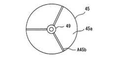
- the first end plate 45has a disk shape.
- the first end plate 45is provided at the upper end of the element 13.
- the first end plate 45defines the outer diameter of the upper end of the element 13.
- the first end plate 45has a connection portion 49.
- the connection part 49is inserted into the connection pipe 24.
- the first end plate 45defines an opening 49 a for an outlet passage that the connection portion 49 defines.
- the opening 49aopens in a circular shape on the lower end surface of the first end plate 45, that is, the end surface on the filter medium 30 side.
- the first end plate 45has an adhesive layer 51.
- the adhesive layer 51is provided between the opening 49 a and the outer edge of the first end plate 45.
- the adhesive layer 51joins the upper end of the first filter medium 31 and the first end plate 45. As a result, the upper end of the first filter medium 31 is blocked by the first end plate 45 and the adhesive layer 51.
- the adhesive layer 51joins the upper end of the first frame 41 and the first end plate 45.
- the adhesive layer 51joins the upper end of the second frame 42 and the first end plate 45.
- the adhesive layer 51joins the upper end of the third filter medium 33 and the first end plate 45. As a result, the upper end of the third filter medium 33 is blocked by the first end plate 45 and the adhesive layer 51.
- the adhesive layer 51joins the upper end of the third frame 43 and the first end plate 45. *
- the first end plate 45provides a wide annular surface extending over all of the first filter medium 31, the first frame 41, the second frame 42, the third filter medium 33, and the third frame 43.
- the first end plate 45is joined to the first filter medium 31, the first frame 41, the second frame 42, the third filter medium 33, and the third frame 43 by the adhesive layer 51. All the filter media are supported on the lower side of the first end plate 45.
- the first end plate 45is also called an end plate common to the outer layer filter medium and the inner layer filter medium. The first end plate 45 enables the multilayer filter medium 30 to be arranged with a simple configuration. *
- the second end plate 46is annular.
- the second end plate 46is provided at the lower end of the element 13.
- the second end plate 46has a cylindrical leg.
- the leg portionsupports the seal mechanism 17.
- the second end plate 46defines the outer diameter of the lower end of the element 13.
- the seal mechanism 17seals between the second end plate 46 and the cup 26.
- the second end plate 46has an adhesive layer 52. *
- the adhesive layer 52joins the lower end of the first filter medium 31 and the second end plate 46. As a result, the lower end of the first filter medium 31 is blocked by the second end plate 46 and the adhesive layer 52.
- the adhesive layer 52joins the lower end of the first frame 41 and the second end plate 46.
- the third end plate 47has a disk shape.
- the third end plate 47is provided at the lower end of the element 13.
- the third end plate 47is disposed on the radially inner side of the second end plate 46.
- the third end plate 47has an adhesive layer 53. *
- the adhesive layer 53joins the lower end of the second frame 42 and the third end plate 47.
- the adhesive layer 53joins the lower end of the third filter medium 33 and the third end plate 47.
- the lower end of the third filter medium 33is blocked by the third end plate 47 and the adhesive layer 53.
- the adhesive layer 53joins the lower end of the third frame 43 and the third end plate 47.
- the first frame 41connects the first end plate 45 and the second end plate 46 to provide an inner frame for the outer layer filter medium.
- the third frame 43connects the first end plate 45 and the third end plate 47 and provides an inner frame for the inner layer filter medium.
- the second frame 42connects the first end plate 45 and the third end plate 47.
- the second frame 42is located outside the inner layer filter medium in the radial direction, thereby providing an outer frame for the inner filter medium, that is, the third filter medium 33.
- the second frame 42provides a forming member that partitions the separation chamber 36 between the first frame 41 and the third filter medium 33.
- the sealing mechanisms 16 and 17seal between the upper case 11 and the lower case 12 and the first end plate 45 and the second end plate 46.
- the seal mechanisms 16 and 17allow the first end plate 45 and the second end plate 46 to move in the axial direction with respect to the upper case 11 and the lower case 12. That is, the element 13 is supported in the upper case 11 and the lower case 12 so as to be slightly movable in the axial direction.
- the upper case 11 and the lower case 12are formed such that the O-ring and lip seals that provide the sealing mechanisms 16, 17 are in contact with the cylindrical surface.
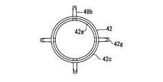
- the second frame 42has a plurality of ribs 48.
- the rib 48is plate-shaped.
- the rib 48has a thin plate shape having a thickness comparable to the circumferential width of the column 42f.
- the rib 48extends along the radial direction and the axial direction.
- the rib 48is provided on the radially outer side of the column 42f.
- the rib 48is also a part of the column 42f.
- the plurality of ribs 48are integrally formed with the plurality of columns 42f by resin.
- the rib 48is provided on a part of the plurality of pillars 42f. Therefore, the second frame 42 also has a column 42 f that does not have the rib 48.
- the rib 48extends from the second frame 42 outward in the radial direction.
- the rib 48allows a radial flow and an axial flow in the separation chamber 36.
- the rib 48is formed so as not to obstruct the flow that penetrates the separation chamber 36 in the radial direction and the axial flow over the entire height of the separation chamber 36.
- the rib 48is disposed between the first frame 41 and the second frame 42.
- the rib 48is also called a radial rib extending in the radial direction between the two frames 41 and 42 in the outer frame.
- the radially outer end of the rib 48is in contact with the inner surface of the first frame 41 or is opposed to the inner surface of the first frame 41.
- the rib 48is located on the radially inner side of the thick pillar 41 m of the first frame 41.
- the ribs 48are provided at both ends of the second frame 42 in the axial direction.
- the plurality of ribs 48support the first frame 41 from the inside in the radial direction by providing contact between the first frame 41 and the second frame 42. *
- the rib 48serves to define the separation chamber 36.
- the rib 48supports the first frame 41 from the radially inner side. For example, when the first frame 41 attempts to deform radially inward, the rib 48 contacts the inner surface of the first frame 41 and suppresses deformation of the first frame 41 inward in the radial direction.
- the adhesive layers 51, 52, 53are formed by curing the end plates 45, 46, 47 after being joined to other members in a melted state by heating.
- the adhesive layers 51, 52, 53may be provided by a thermoplastic resin such as hot melt.
- a cylindrical cavity defined by a plurality of ribs 48 between the first frame 41 and the second frame 42is located above the storage chamber 28 and communicates directly with the storage chamber 28 in the vertical direction. This configuration facilitates settling of the separated water into the storage chamber 28.
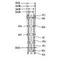
- FIG. 4shows a longitudinal section of the first frame 41.
- FIG. 5is a view taken in the direction of arrow V in FIG.
- the first frame 41is made of resin.
- the first frame 41is an integrally molded product.
- the first frame 41is a cylindrical member that is open at both ends.
- the first frame 41defines a plurality of openings 41a through which fuel passes through the cylindrical wall.
- the first frame 41has a net shape or a cage shape. *
- the first frame 41has a plurality of beams 41b, 41c, 41d extending along a plane orthogonal to the central axis AX.
- the plurality of beams 41b, 41c, 41dare formed in an annular shape.
- the first frame 41has an end beam 41b provided at the upper end and an end beam 41c provided at the lower end.
- the end beams 41b and 41chave a shape that can be called a short cylindrical shape.
- the first frame 41is formed vertically symmetrical.
- the first frame 41can be used upside down.
- the end beams 41b and 41chave a large diameter portion and a small diameter portion. *
- the large-diameter portionhas a cylindrical outer surface on the radially outer side.
- the cylindrical outer surfacehas an outer diameter D41L.
- the outer diameter D41Lis also called an end outer diameter.
- the end beams 41b and 41care in contact with the radially inner surface of the first filter medium 31 at the large diameter portion.
- the end beams 41b and 41cprovide end support portions that support the first filter medium 31 from the radially inner side at both axial ends. *
- the small diameter portionhas a cylindrical outer surface on the radially outer side.
- the cylindrical outer surfacehas an outer diameter D41S.
- the outer diameter D41Sis smaller than the outer diameter D41L.
- the end beams 41b and 41care in contact with the radially inner surface of the second filter medium 32 at the small diameter portion.
- the end beams 41b and 41cprovide end support portions that support the second filter medium 32 in the radial direction at both axial ends thereof. *
- the first frame 41has a plurality of intermediate beams 41d provided between the upper end and the lower end.
- the plurality of intermediate beams 41dare provided apart from each other in the axial direction.
- the intermediate beam 41dis an annular member. *
- An annular receiving groove 41eis formed in the end beams 41b and 41c.
- the receiving groove 41eis formed as a recess at the inner corner of the ends of the end beams 41b and 41c.
- the receiving groove 41 eis used for connection with the second frame 42.
- a plurality of grooves 41fare formed in the end beams 41b and 41c.
- the plurality of grooves 41fare formed as grooves deeper in the axial direction than the receiving groove 41e.
- the plurality of grooves 41fare arranged away from each other in the circumferential direction.
- the plurality of grooves 41 fare used for positioning the first frame 41 and the second frame 42. *
- the plurality of intermediate beams 41dhave the same inner diameter.
- the plurality of intermediate beams 41dinclude a small-diameter beam 41g and a large-diameter beam 41h having different outer diameters.
- the large-diameter beam 41hhas a larger diameter than the small-diameter beam 41g.
- two small-diameter beams 41g and three large-diameter beams 41hare provided.
- the large-diameter beam 41his provided in the central portion of the first frame 41 in the axial direction. *
- the large-diameter beam 41 hprovides an annular protrusion 41 i on the radially outer surface of the first frame 41.
- the annular protrusion 41iextends so as to surround the first frame 41 along the circumferential direction.
- the annular protrusion 41 iis provided at the center of the first frame 41 in the axial direction.
- the annular protrusion 41ihas an outer diameter D41M.
- the outer diameter D41Mis slightly smaller than the outer diameter D41L and slightly larger than the outer diameter D41S (D41S ⁇ D41M ⁇ D41L).
- the annular protrusion 41 isupports the first filter medium 31 from the radially inner side via the second filter medium 32.
- the annular protrusion 41iprovides an intermediate support part that supports the first filter medium 31 in the axial direction in the radial direction. *
- the annular protrusion 41iextends so as to be orthogonal to the inner peak of the first filter medium 31 bent into a pleat shape. Even if the first filter medium 31 is strongly pressed against the annular protrusion 41i, the portion of the first filter medium 31 that is covered and closed by the annular protrusion 41i is the intersection of the inner peak and the annular protrusion 41i. is there. Therefore, the first filter medium 31 can be supported from the radially inner side while suppressing a decrease in the filtration area of the first filter medium 31.
- the first frame 41has a plurality of pillars 41j extending along the axial direction.
- the plurality of columns 41jconnect the plurality of beams 41b, 41c, and 41d.
- the plurality of pillars 41jinclude a thin pillar 41k and a thick pillar 41m that is thicker than the thin pillar 41k.
- the thick pillar 41mhas a relatively thick cross-sectional shape for increasing the mechanical strength of the first frame 41.
- the thick pillar 41mis positioned corresponding to the plurality of grooves 41f.
- a virtual circle defined by the radially outer surfaces of the plurality of columns 41jhas an outer diameter D41S. *
- the second filter medium 32is supported by the outer surfaces of the small-diameter portions of the end beams 41b and 41c, the outer surfaces of the plurality of intermediate beams 41d, and the outer surfaces of the plurality of columns 41j. These portions are provided between the two end beams 41b and 41c and have a small outer diameter D41S smaller than the end outer diameter D41L. These portions provide a small-diameter portion that supports the second filter medium 32 from the radially inner side.
- the 2nd filter medium 32may be adhere
- the plurality of outer diameter relationships D41S ⁇ D41M ⁇ D41L in the first frame 41contribute to suppressing the compression of the second filter medium 32 and maintaining the thickness of the second filter medium 32.
- the plurality of pillars 41jhave a surface inclined with respect to the fuel flowing from the outside toward the inside along the radial direction.
- This surfaceis a flat surface or a curved surface.
- the cross section of the thick pillar 41mhas a shape that can be called a triangle or a trapezoid.
- the thick pillar 41mis formed with an inclined surface for suppressing fluid resistance against the flow of fuel.
- the thin column 41kis a prism with rounded corners.
- the thin column 41kis also given a cross-sectional shape that suppresses fluid resistance.
- the rib 48is not positioned on the radially inner side of the thin column 41k.
- a rib 48is positioned on the radially inner side of the thick pillar 41m.
- the first filter medium 31is supported by the end beams 41b and 41c.
- the second filter medium 32is supported by the small diameter portion.
- the difference between the end outer diameter D41L and the small outer diameter D41Scontributes to suppress the compression of the second filter medium 32.
- the second filter medium 32is in contact with the radially outer surface of the small diameter part, and a gap is formed between the first filter medium 31 and the second filter medium 32 on the radial outer side of the small diameter part. This gap may be filled with the second filter medium 32.
- the first frame 41has an intermediate beam 41h.
- a second filter medium 32is interposed between the first filter medium 31 and the first frame 41.
- the intermediate beam 41hsupports the second filter medium 32.
- the intermediate beam 41 hsupports the first filter medium 31 via the second filter medium 32.
- FIG. 6shows a longitudinal section of the second frame 42.
- 7is a view taken along arrow VII in FIG.
- the second frame 42is made of resin.
- the second frame 42is an integrally molded product.
- the second frame 42is a cylindrical member that is open at both ends.
- the second frame 42defines a plurality of openings 42a for allowing fuel to pass through the cylindrical wall.
- the second frame 42has a net shape or a cage shape. *
- the second frame 42has a plurality of beams 42b, 42c, and 42d extending along a plane orthogonal to the central axis AX.
- the plurality of beams 42b, 42c, and 42dare formed in an annular shape.
- the second frame 42includes an end beam 42b provided at the upper end and an end beam 42c provided at the lower end.
- the end beams 42b and 42chave a shape that can be called a short cylindrical shape.
- the second frame 42has a plurality of intermediate beams 42d provided between the upper end and the lower end.
- the plurality of intermediate beams 42dare provided away from each other in the axial direction.
- the intermediate beam 42dis an annular member.
- the plurality of intermediate beams 42dhave the same inner diameter.
- the plurality of intermediate beams 42dhave the same outer diameter. *
- the end beam 42c at the lower endhas a receiving groove 42e for receiving the third end plate 47 on the radially inner side.
- the receiving groove 42 edefines the axial position and the radial position of the third end plate 47.
- the second frame 42has a plurality of pillars 42f extending along the axial direction.
- the plurality of pillars 42fconnect the plurality of beams 42b, 42c, and 42d.
- the plurality of columns 42fhave the same thickness. *
- the second frame 42has a plurality of protrusions 42g on the radially outer side of the upper end beam 42b.
- the plurality of protrusions 42 gare fitted into the plurality of grooves 41 f provided in the first frame 41.
- the plurality of grooves 41f and the plurality of protrusions 42gprovide a positioning mechanism for positioning the rib 48 on the radially inner side of the thick pillar 41m. Therefore, the first frame 41 and the second frame 42 include positioning mechanisms 41 f and 42 g for positioning the plurality of ribs 48 on the radially inner side of the plurality of thick pillars 41 m of the first frame 41. *
- the second frame 42has a rib 48.
- the second frame 42has an upper rib 48a provided at the upper part and a lower rib 48b provided at the lower part.
- the upper rib 48aextends over the radially outer side of the end beam 42b and the radially outer side of the column 42f.
- the upper rib 48acontacts the inner surface of the first frame 41 to position the first frame 41 and the second frame 42 in the radial direction.
- the lower rib 48bis provided on the radially outer side of the column 42f.
- the lower rib 48bcontacts the inner surface of the first frame 41 to position the first frame 41 and the second frame 42 in the radial direction.
- the upper rib 48a and the lower rib 48bare disposed away from each other in the axial direction.
- FIG. 8shows a longitudinal section of the third frame 43.
- the third frame 43is made of resin.
- the third frame 43is an integrally molded product.
- the third frame 43is a cylindrical member that is open at both ends.
- the third frame 43defines a plurality of openings 43a for allowing fuel to pass through the cylindrical wall.
- the third frame 43has a net shape or a cage shape. *
- the third frame 43includes an end beam 43b provided at the upper portion and an end beam 43c provided at the lower portion.
- the end beams 43b and 43care annular members.
- the third frame 43is formed vertically symmetrical.
- the third frame 43can be used upside down.
- the end beams 43b and 43chave a cylindrical outer surface on the radially outer side.
- the cylindrical outer surfacehas an outer diameter D43M.
- the end beams 43b and 43care in contact with the radially inner surface of the third filter medium 33 on the cylindrical outer surface.
- the end beams 43b and 43cprovide end support portions that support the third filter medium 33 in the radial direction at both ends in the axial direction. *
- the third frame 43has a plurality of intermediate beams 43d provided between the upper end and the lower end.
- the plurality of intermediate beams 43dare provided apart from each other in the axial direction.
- the intermediate beam 43dis an annular member. *
- the end beams 43b and 43c and the plurality of intermediate beams 43dhave the same inner diameter D43N.
- the end beams 43b and 43chave an outer diameter D43M.
- the plurality of intermediate beams 43dinclude a small-diameter beam 43e and a large-diameter beam 43f having different outer diameters.
- the small-diameter beam 43ehas an outer diameter D43M.
- the large-diameter beam 43fhas a larger diameter than the small-diameter beam 43e.
- the large-diameter beam 43fhas an outer diameter D43L.
- the outer diameter D43Lis slightly larger than the outer diameter D43M.
- two small-diameter beams 43e and one large-diameter beam 43fare provided.
- the large-diameter beam 43fis provided in the central portion of the third frame 43 in the axial direction. *
- FIG. 9shows a cross section of the radially outer end of the small-diameter beam 43e.
- the small-diameter beam 43eprovides an annular protrusion 43g.
- the top surface of the annular protrusion 43gdefines the outer diameter D43M.
- the annular protrusion 43gsupports the third filter medium 33 from the inside in the radial direction by contacting a plurality of peaks on the inner peripheral surface of the third filter medium 33.
- FIG. 10shows a cross section of the radially outer end of the large-diameter beam 43f.
- the large-diameter beam 43fprovides an annular protrusion 43g.
- the annular protrusion 43gsupports the third filter medium 33 from the inside in the radial direction by contacting a plurality of peaks on the inner peripheral surface of the third filter medium 33.
- the large-diameter beam 43fhas an annular small protrusion 43h that extends further outward in the radial direction from the annular protrusion 43g.
- the annular small protrusion 43his formed on the top surface of the annular protrusion 43g, that is, the outer peripheral surface, by a thin protrusion extending in an annular shape.
- the top surface of the annular small protrusion 43hdefines an outer diameter D43L.
- the annular small protrusion 43hextends so as to surround the third frame 43 along the circumferential direction.
- the small annular protrusion 43 his provided in the central portion of the third frame 43 in the axial direction.
- the plurality of intermediate beams 43dinclude a large-diameter beam 43f including an annular small protrusion 43h and a small-diameter beam 43e not including the annular small protrusion 43h. *
- the annular small protrusion 43 his in strong contact with a plurality of peaks on the inner peripheral surface of the third filter medium 33.
- the annular small protrusion 43 helastically deforms the peak of the inner surface of the third filter medium 33 when the third frame 43 is inserted into the third filter medium 33.
- the annular small protrusion 43 hmay partially plastically deform the peak of the inner surface of the third filter medium 33.
- the annular small protrusion 43 hrealizes loose connection between the third filter medium 33 and the third frame 43.
- the annular small protrusion 43 hprovides a connecting portion that connects the third filter medium 33 and the third frame 43 at an intermediate portion in the axial direction of the third frame 43. This connecting portion provides a fit that prevents the third frame 43 from falling out of the third filter medium 33. As a result, the third filter medium 33 and the third frame 43 can be handled as one component. *
- the end beams 43b and 43c and the plurality of intermediate beams 43dextend so as to be orthogonal to the inner peak of the third filter medium 33 bent into a pleat shape.
- the third filter medium 33is supported by the outer surfaces of the end beams 43b and 43c and the outer surfaces of the plurality of intermediate beams 43d. Therefore, the end beams 43b and 43c and the plurality of intermediate beams 43d can support the third filter medium 33 from the radially inner side while suppressing a decrease in the filtration area of the third filter medium 33.
- the third frame 43has a plurality of pillars 43i extending along the axial direction.
- the plurality of pillars 43iconnect the plurality of beams 43b, 43c, and 43d.
- a virtual circle defined by the radially outer surfaces of the plurality of columns 43ihas an outer diameter D43S.
- the outer diameters D43S, D43M, and D43Lprovide a relationship of D43S ⁇ D43M ⁇ D43L. *
- the third frame 43has a plurality of leg portions 43j and 43k extending in the axial direction from the end portion.
- the leg portions 43j and 43kare rod-shaped protrusions that terminate at the end portions.
- the leg portions 43j and 43kfurther extend in the axial direction from the end beams 43b and 43c.
- the leg portions 43j and 43kextend on the extension of the plurality of columns 43i.
- the plurality of leg portions 43j and 43kare disposed slightly outward in the radial direction from the plurality of columns 43i.
- a virtual circle defined by the radially outer surfaces of the plurality of leg portions 43j and 43khas an outer diameter D43L.
- a virtual circle defined by the radially inner surfaces of the plurality of leg portions 43j and 43khas an inner diameter D43W.
- the inner diameter D43Wis larger than the inner diameter D43N (D43N ⁇ D43W). *
- the plurality of upper leg portions 43 jare joined to the first end plate 45 by the adhesive layer 51.
- the plurality of leg portions 43jare inserted deeply into the adhesive layer 51.
- the plurality of leg portions 43jprovide a wide bonding surface and various shapes of bonding surfaces.
- the 3rd frame 43 and the 1st end plate 45are joined firmly.
- the plurality of leg portions 43 k at the lower endare joined to the third end plate 47 by the adhesive layer 53.
- the plurality of leg portions 43kare inserted deeply into the adhesive layer 53.
- the plurality of leg portions 43kprovide a wide bonding surface and various shapes of bonding surfaces.
- the third frame 43 and the third end plate 47are firmly joined. *
- the plurality of leg portions 43j and 43kare rod-shaped. Therefore, the plurality of leg portions 43j and 43k are inserted into the adhesive layer without excessively pushing the adhesive layer. Thereby, the outflow of the adhesive layer 51 to the opening 49a is suppressed.
- the inner diameter D43W defined by the plurality of leg portions 43jis larger than the inner diameter of the opening portion 49a of the outlet passage.
- the leg 43jis positioned on the lower surface of the first end plate 45 by a predetermined width away from the opening 49a in the radial direction.
- the plurality of leg portions 43jare inserted into the adhesive layer 51 in a molten state. At this time, a part of the adhesive layer 51 may flow inward in the radial direction by the plurality of leg portions 43j. Since the leg 43j is positioned on the radially outer side than the opening 49a, the flowing adhesive layer 51 is suppressed from flowing toward the opening 49a.
- the third frame 43 and the first end plate 45are joined while suppressing the flow of the adhesive layer 51. For this reason, the reduction of the area of the opening part 49a of the exit channel
- FIG. 11shows a shape before joining the second frame 42 and the third end plate 47.
- FIG. 12shows the shape after joining the second frame 42 and the third end plate 47.
- the manufacturing method of the element 13including the process of joining the 2nd frame 42 and the 3rd end plate 47 is demonstrated. *
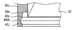
- the second frame 42has an annular receiving groove 42e at the inner corner of the lower end beam 42c.
- the receiving groove 42eprovides a recess for receiving the third end plate 47 from the end of the second frame 42 to the inside of the end beam 42c.
- the end beam 42chas a small diameter portion 42j having a relatively small inner diameter at the entrance of the receiving groove 42e.
- the small diameter portion 42 jhas an inner diameter that can receive the third end plate 47.
- the small diameter portion 42jcontributes to the positioning of the third end plate 47 in the radial direction.
- the end beam 42chas a large-diameter portion 42k having an inner diameter larger than that of the small-diameter portion 42j at the back of the small-diameter portion 42j, in other words, above.
- the large diameter portion 42kis formed between the bottom portion of the receiving groove 42e and the small diameter portion 42j.
- the large diameter portion 42kis defined by a slope inclined so as to spread radially outward from the
- the end beam 42chas a plurality of grooves 42m behind the receiving groove 42e from the large diameter portion 42k.
- the plurality of grooves 42mfurther extend in the axial direction from the bottom of the receiving groove 42e.
- the plurality of grooves 42mare formed away from each other in the circumferential direction.
- the plurality of grooves 42mare formed so as to extend further above the receiving groove 42e. *
- the third filter medium 33is positioned in the second frame 42.
- the third end plate 47carries a molten adhesive layer 53.
- the third end plate 47is pushed into the receiving groove 42 e from the lower opening of the second frame 42.
- An end plateis received in the end beam.
- the radial position of the end plateis defined by the small diameter portion. A part of the adhesive layer may try to leak outward in the radial direction of the end plate and further from the inside to the outside of the end beam.
- the adhesive layer 53contacts the end face of the third filter medium 33.
- the adhesive layer 53closes the end surface of the third filter medium 33.
- the adhesive layer 53joins the third filter medium 33 and the third end plate 47. A part of the adhesive layer 53 is pushed into the groove 42m.
- the adhesive layer 53enters the plurality of grooves 42m. Thereby, the rotation of the third end plate 47 is prevented.
- a part of the adhesive layer 53flows out radially outward to become an irregular adhesive layer 53a having an irregular shape.
- the small diameter portion 42j and the third end plate 47prevent the indeterminate adhesive layer 53a from flowing out.
- the amorphous adhesive layer 53aaccumulates in the large diameter portion 42k. Soon, the adhesive layer 53 is cured again. Thereby, a joining process is completed.
- the small-diameter portion 42jdefines an opening end that opens downward. For this reason, the boundary between the second frame 42 and the third end plate 47 is positioned on the radially inner side of the end face.
- Such an arrangementsuppresses the exposure of the amorphous adhesive layer 53a to the outer peripheral surface of the second frame 42. Further, the irregular adhesive layer 53a from which the large-diameter portion 42k is about to flow is accumulated. Therefore, the large-diameter portion 42k also suppresses the exposure of the amorphous adhesive layer 53a to the outer peripheral surface of the second frame 42.
- a portion 53a of the adhesive layerenters between the outer peripheral surface of the third end plate 47 and the large diameter portion 42k.
- the storage chamber 28is positioned under the end beam 42 c.
- the smooth surfacepromotes the flow of water droplets WD. Further, the smooth surface promotes separation of the water droplet WD from the lower end of the second frame 42. As a result, water droplets WD are suppressed from accumulating at the lower end of the second frame 42.
- the water droplet WDflows down on the surface of the second frame 42, the water droplet WD can flow down without being obstructed by the irregular portion formed by the portion 53a of the adhesive layer.
- the water droplet WDflows smoothly toward the storage chamber 28.
- FIG. 13shows an example of a preliminary assembly state of the element 13 and the cap 21.
- the element 13When the element 13 is accommodated between the upper case 11 and the lower case 12, the element 13 may come into contact with the open end 21a of the cap 21.
- the element 13when the element 13 is disposed in the cup 26 and the cup 26 is connected to the cap 21, the element 13 temporarily held at a slightly raised position comes into contact with the opening end 21 a of the cap 21 and is pressed.
- the first end plate 45defines a gap between the first end plate 45 and the opening end 21a by partially contacting the opening end 21a.
- the first end plate 45has a disc portion 45a that is a circular flat plate.
- the disc part 45ahas a size that can cover the open end 21a.
- the disc part 45ais arrange
- the 1st end plate 45has the spacer 45b which contacts the opening end 21a.
- the spacer 45bis provided by a radially extending protrusion.
- the spacer 45bdefines a passage for allowing the passage of fuel between the opening end 21a. *
- the spacer 45 bis provided on the upper surface of the first end plate 45.
- the spacer 45 bis a protrusion that protrudes further upward from the upper surface of the first end plate 45.
- the spacer 45 bis provided by a plurality of radial ridges extending elongated along the radial direction of the first end plate 45.
- the spacer 45 bcontacts the open end 21 a of the cap 21.
- the spacer 45bis in contact with the open end 21a at a radially outer portion of the element 13. Therefore, the inclination of the element 13 is suppressed. Thereby, the element 13 is accommodated between the upper case 11 and the lower case 12 in a normal posture.
- the spacer 45bprovides a gap for the fuel to pass even if the opening end 21a and the first end plate 45 are in contact with each other. Therefore, the fuel passage is reliably formed.
- fuelis supplied from the fuel tank 2 to the filter 10 by the supply pump 4.
- the fuelis filtered by the filter 10 and supplied to the injection device 5.
- the fuelis pressurized by the injection device 5 and supplied to the internal combustion engine 3.
- fuelis supplied from the inlet 22 into the gallery 23.
- the fuel introduced from the inlet 22reaches the outer chamber 35 via the radially outer side of the first end plate 45.
- the fuelflows downward in the outer chamber 35.
- the fuelsequentially passes through the plurality of filter media 31, 32, and 33 arranged on the same axis.
- the fuelfirst passes through the first filter medium 31 in the radial direction.
- the first filter medium 31mainly removes solid foreign matters from the fuel.
- the fuelpasses through the second filter medium 32 in the radial direction.
- the second filter medium 32captures moisture mixed in the fuel.
- the second filter medium 32grows water droplets by aggregating moisture.
- the fuelpasses through the first frame 41 and reaches the separation chamber 36.
- water droplets or the like mixed in the fuelare settled by gravity.
- the settled water dropletsare sorted out. For example, moisture settles in the storage chamber 28 and is stored. *
- the fuelpasses through the second frame 42 and reaches the third filter medium 33.
- the third filter medium 33allows the fuel to pass therethrough and inhibits the passage of moisture. As a result, the moisture flows down the surface or the inside of the third filter medium 33 and settles into the storage chamber 28 from the lower end of the second frame 42. In this embodiment, since the leakage of the adhesive layer 53 to the outer peripheral surface of the second frame 42 is suppressed, water droplets flow smoothly from the lower end of the second frame 42.
- the fuelpasses through the third filter medium 33. Further, the fuel passes through the third frame 43 and reaches the inner chamber 37. The fuel flows with the inner chamber 37 facing upward. The fuel flows out from the filter 10 via the connection portion 49, the connection pipe 24, and the outlet pipe 25. *
- the outer layer provided by the first filter medium 31 and the second filter medium 32 and the inner layer provided by the third filter medium 33are disposed on the common first end plate 45.
- This configurationmakes it possible to provide the multilayer element 13 with a small number of parts.
- the first frame 41 and the second frame 42provide an outer frame having high rigidity.
- the rib 48supports the first frame 41 from the radially inner side.
- the second frame 42defines a separation chamber 36 between the outer layer provided by the first filter medium 31 and the second filter medium 32 and the inner layer provided by the third filter medium 33.
- the separation chamber 36 for allowing the water to settleis partitioned and formed reliably.
- the third frame 43supports the third filter medium 33 from the radially inner side of the third filter medium 33. Therefore, even if a large pressure difference acts on the third filter medium 33 in the radial direction, the third filter medium 33 is maintained in a prescribed shape.
- the third frame 43is in strong contact with the third filter medium 33 by the large-diameter beam 43f. For this reason, in the temporary assembly state in which the third frame 43 is positioned in the third filter medium 33, the third frame 43 is prevented from falling out of the third filter medium 33. For example, in the joining process of joining the third filter medium 33 and the third frame 43 to the first end plate 45 and the third end plate 47, the third filter medium 33 and the third frame 43 are handled as an integrated part. Can do. Therefore, according to this structure and manufacturing method, the element 13 can be easily manufactured.
- the first end plate 45has a spacer 45b that is in contact with the open end 21a of the cap 21 and that defines a fuel passage. For this reason, the inclination of the element 13 is suppressed.
- the element 13is accommodated at a predetermined position between the upper case 11 and the lower case 12. Moreover, even if the element 13 contacts the opening end 21a, a fuel passage is ensured.
- This embodimentis a modification which makes previous embodiment a basic form.
- the thick pillar 41m having a trapezoidal cross sectionis employed.
- various shapes of thick pillarscan be employed.
- the first frame 41may employ a thick pillar 241m having a triangular cross section. Even in this shape, the first frame 41 having high rigidity is provided while suppressing resistance to fuel. *
- the first frame 41may employ a thick pillar 341m having a square cross section with rounded corners on the radially outer side. Even in this shape, the same effect as the preceding embodiment can be obtained.
- This embodimentis a modification which makes previous embodiment a basic form.
- two ribs 48 a and 48 b that are separated in the axial directionare provided on the second frame 42.
- various shapes of ribscan be employed.
- the second frame 42may include a lower rib 448 positioned also on the radially outer side of the end beam 42 c. Even in this shape, the second frame 42 can support the first frame 41 from the radially inner side. Moreover, the deformation of the outer layer and the inner layer in the radial direction can be suppressed at the lower end of the element 13.
- the second frame 42may include a rib 548 that extends over the entire length of the second frame 42 in the axial direction. Even in this shape, the same effect as the preceding embodiment can be obtained.
- This embodimentis a modification in which the preceding embodiment is a basic form.
- the second frame 42may include an independent central rib 648 at the central portion in the axial direction of the second frame 42. Even in this shape, the same effect as the preceding embodiment can be obtained.
- FIG. 20shows an exploded state of the first frame 41 and the second frame 42.
- the second frame 42includes an end beam 742b formed by an annular plate.
- the end beam 742 cprovides a plane that faces the first end plate 45.
- the upper plane of the end beam 742bis bonded to the adhesive layer 51.
- the second frame 42includes only the central rib 648.
- the first frame 41has a receiving groove 41e that can receive the end beam 742b.
- the fitting structureas a positioning mechanism that provides the circumferential positioning of the first frame 41 and the second frame 42 is not provided. *
- FIG. 21is a view taken along arrow XXI in FIG.
- the rib 648is oriented in any direction with respect to the circumferential direction. Therefore, the rib 648 may be disposed inside the opening 41a.
- the rib 648is supported from the radially inner side of the first frame 41 by contacting the inner surface of the first frame 41. *
- the rib 648even if the rib 648 is disposed inside the opening 41a, the rib 648 has a plate shape, and thus the resistance to the fuel flow is low. Even in this shape, the second frame 42 can support the first frame 41 from the radially inner side.
- the first frame 41may include a rib 848.
- the second frame 42may be configured without the rib 48.
- FIG. 23is a view taken along arrow XXIII in FIG.
- the plurality of ribs 848extend radially inward from the inner surface of the first frame 41.
- the plurality of ribs 848are integrally formed with the plurality of columns 41m of the first frame 41 by resin.
- the first frame 41 and the second frame 42include a positioning mechanism for positioning the plurality of ribs 848 on the radially outer side of the plurality of pillars 42f of the second frame.
- the distal end surface on the radially inner side of the rib 848is positioned so as to be in contact with or in close proximity to the outer surface of the beams 42b, 42c, 42d of the second frame 42 or the outer surface of the column 42f. Even in this shape, the second frame 42 can support the first frame 41 from the inside in the radial direction via the rib 848. *
- the first end plate 45has a short spacer 945b provided corresponding to only a portion that can come into contact with the opening end 21a.
- the short spacers 945bare provided by radially extending ridges.
- the short spacer 945bis provided at least on the outer peripheral portion of the disc portion 45a.
- the short spacer 945 bdefines the fuel passage while suppressing the inclination of the element 13.
- This embodimentis a modification example in which the preceding embodiment is a basic form.
- the first end plate 45has three spacers A45b arranged radially.
- the spacer A45bis provided by radially extending protrusions. Also in this embodiment, the same effect as the preceding embodiment can be obtained. *
- the end beam 42chas a large-diameter portion B42k defined by two conical inner surfaces arranged opposite to each other.
- the large-diameter portion B42kcan also store the adhesive layer 53 that flows out.
- the disclosure of this specificationis not limited to the illustrated embodiments.
- the disclosureencompasses the illustrated embodiments and variations by those skilled in the art based thereon.
- the disclosureis not limited to the combinations of parts and / or elements shown in the embodiments.
- the disclosurecan be implemented in various combinations.
- the disclosuremay have additional parts that can be added to the embodiments.
- the disclosureincludes those in which parts and / or elements of the embodiments are omitted.
- the disclosureencompasses the replacement or combination of parts and / or elements between one embodiment and another.
- the technical scope disclosedis not limited to the description of the embodiments. Some technical scope disclosed is indicated by the description of the claims, and should be understood to include all modifications within the meaning and scope equivalent to the description of the claims. . *
- the filter 10which can replace
- part or all of the element 13 and the cup 26may be connected so as not to be disassembled, and a cartridge-type filter in which they can be replaced may be provided.
- the shape of the 1st filter medium 31, the 2nd filter medium 32, and the 3rd filter medium 33is not limited to the shape shown in figure.
- the second filter medium 32may be provided by a filter medium folded in a pleat shape.
- the third filter medium 33may be provided by a mesh that is not bent into a pleat shape, or a non-woven fabric.
- each of the first filter medium 31, the second filter medium 32, and the third filter medium 33may be provided by a single-layer or multilayer filter medium. *
- the first frame 41 and the second end plate 46may be integrally molded with resin.
- the first frame 41 and the second frame 42may be integrally formed with resin.
- a cylindrical outer frameis provided.
- the outer peripheral portion of the outer frameis defined by a plurality of beams, a plurality of columns, and a plurality of ribs. This outer peripheral portion is given a thickness corresponding to the separation chamber 36. The fuel can flow radially and axially in this outer peripheral portion.
- a corrugated platemay be provided along the outer peripheral portion of the disc portion 45a.
- youmay provide the several recessed part opened to an upper surface and an outer peripheral surface in the outer peripheral part of the disc part 45a. Even in these configurations, the element 13 can be stably positioned on the cap 21 while avoiding the blocking of the open end 21a by the disc portion 45a.
Landscapes
- Engineering & Computer Science (AREA)
- Chemical & Material Sciences (AREA)
- Chemical Kinetics & Catalysis (AREA)
- Combustion & Propulsion (AREA)
- Mechanical Engineering (AREA)
- General Engineering & Computer Science (AREA)
- Filtration Of Liquid (AREA)
Abstract
Description
Translated fromJapanese本出願は、当該開示内容が参照によって本出願に組み込まれた、2015年8月17日に出願された日本特許出願2015-160526を基にしている。This application is based on Japanese Patent Application No. 2015-160526 filed on August 17, 2015, the disclosure of which is incorporated herein by reference.
この明細書における開示は、燃料フィルタおよびエレメントに関する。The disclosure herein relates to fuel filters and elements.
特許文献1は、複数の筒状のエレメントを同軸上に配置したフィルタ装置を開示する。径方向内側に配置されるエレメントは、内部のフレームを備えない。2つのエレメントは、独立した筒状体を形成しており、組み付け時に同軸上に配置される。
特許文献2は、複数の筒状のエレメントを同軸上に配置したフィルタ装置を開示する。このフィルタ装置は、エレメントを支持するための内部のフレームを開示している。内部のフレームは、筒状の薄い板である。
特許文献1および特許文献2の構成では、プリーツ状に曲げられたフィルタの内側峰部の広い範囲が補強部材によって覆われる。これでは、濾材の濾過面積が減少する。 In the configurations of
別の観点では、補強部材の厚さ、または補強部材を固定するための構造が、通路面積を狭くする場合がある。よって、補強部材に起因する通路面積の減少を抑制することが求められている。 In another aspect, the thickness of the reinforcing member or the structure for fixing the reinforcing member may reduce the passage area. Therefore, it is required to suppress a reduction in passage area caused by the reinforcing member. *
さらに別の観点では、同軸上に配置される複数の部品は、困難な組み立て作業を要求する場合がある。よって、組立作業が容易な構造が求められている。 In yet another aspect, multiple components arranged on the same axis may require difficult assembly operations. Therefore, there is a demand for a structure that can be easily assembled. *
さらに別の観点では、積層的に配置される複数の濾材は、互いを圧縮し、濾材の機能を低下させる場合がある。 In yet another aspect, the plurality of filter media arranged in a stack may compress each other and reduce the function of the filter media. *
上述の観点において、または言及されていない他の観点において、燃料フィルタおよびエレメントにはさらなる改良が求められている。 In view of the above, or other aspects not mentioned, there is a need for further improvements in fuel filters and elements. *
本開示のひとつの目的は、プリーツ状の濾材の濾過面積の減少を抑制しながら、高い圧力差に耐える燃料フィルタおよびエレメントを提供することである。 One object of the present disclosure is to provide a fuel filter and an element that can withstand a high pressure difference while suppressing a reduction in the filtration area of a pleated filter medium. *
本開示の他のひとつの目的は、濾材を径方向内側から支えるフレームに起因する通路面積の減少が抑制された燃料フィルタおよびエレメントを提供することである。 Another object of the present disclosure is to provide a fuel filter and an element in which a reduction in passage area caused by a frame that supports the filter medium from the radially inner side is suppressed. *
本開示のさらに他のひとつの目的は、複数の部品をひとつの部品として扱うことが可能な燃料フィルタおよびエレメントを提供することである。 Still another object of the present disclosure is to provide a fuel filter and an element capable of handling a plurality of parts as one part. *
本開示のさらに他のひとつの目的は、濾材の圧縮が抑制された燃料フィルタおよびエレメントを提供することである。 Still another object of the present disclosure is to provide a fuel filter and an element in which compression of the filter medium is suppressed. *
本開示の第1態様により、エレメントが提供される。エレメントは、内面に軸方向に延びる複数の峰を形成するようにプリーツ状に折り曲げられており、環状に配置され、径方向に沿って外側から内側へ流れる燃料を濾過する筒状の濾材と、濾材の径方向内側に配置され、燃料を通過させる複数の開口部を区画形成するとともに、濾材を径方向内側から支えるフレームとを備える。フレームは、軸方向の中間部に設けられており、峰と交差して延びる複数の環状の中間梁であって、濾材を径方向内側から支える環状突部を提供する複数の中間梁と、軸方向に沿って延在し、環状突部より径方向内側に配置されており、複数の中間梁を連結する複数の柱とを備える。 According to a first aspect of the present disclosure, an element is provided. The element is folded in a pleat shape so as to form a plurality of ridges extending in the axial direction on the inner surface, arranged in an annular shape, and a cylindrical filter medium that filters fuel flowing from the outside to the inside along the radial direction, A frame that is disposed radially inside the filter medium and that defines a plurality of openings through which the fuel passes and supports the filter medium from the radially inner side. The frame is provided in an intermediate portion in the axial direction, and is a plurality of annular intermediate beams extending across the ridges, the intermediate beams providing annular protrusions that support the filter medium from the inside in the radial direction, and the shaft A plurality of pillars extending along the direction and arranged radially inward from the annular protrusion, and connecting a plurality of intermediate beams. *
環状の濾材は、峰と交差して延びる環状突部によって、径方向内側から支えられる。環状突部は、峰の一部だけに接触するか、または対向して配置されるから、中間梁が濾材を覆う面積は小さく抑えられる。この結果、フレームは、プリーツ状の濾材の濾過面積の減少を抑制しながら、高い圧力差に耐えるように濾材を支える。 The annular filter medium is supported from the inside in the radial direction by an annular protrusion that extends across the peak. Since the annular protrusions are in contact with only a part of the peak or are arranged to face each other, the area where the intermediate beam covers the filter medium can be kept small. As a result, the frame supports the filter medium so as to withstand a high pressure difference while suppressing a decrease in the filtration area of the pleated filter medium. *
本開示の第2態様により、エレメントが提供される。エレメントは、径方向に沿って外側から内側へ流れる燃料を濾過する筒状の濾材、濾材の径方向内側に配置され、燃料を通過させる複数の開口部を区画形成するとともに、濾材を径方向内側から支えるフレーム、濾材およびフレームの端部に配置され、燃料の出口通路の開口部を区画形成する端板、および濾材およびフレームと端板とを接合する接着層を備える。フレームは、接着層に差し込まれることにより端板と接合される複数の棒状の脚部を備える。 According to a second aspect of the present disclosure, an element is provided. The element is a cylindrical filter medium that filters the fuel flowing from the outside to the inside along the radial direction. The element is arranged inside the filter medium in the radial direction and defines a plurality of openings through which the fuel passes, and the filter medium is radially inward. And an end plate that is disposed at the end of the frame, and that defines the opening of the fuel outlet passage, and an adhesive layer that joins the filter medium and the frame to the end plate. The frame includes a plurality of rod-like legs that are joined to the end plate by being inserted into the adhesive layer. *
フレームと端板とは、複数の棒状の脚部が接着層に差し込まれることによって接合される。棒状の脚部は、接着層を過度に押しのけることなく接着層の中に差し込まれる。出口通路の開口部への接着層の流れ出しが抑制される。これにより、接着層に起因する出口通路の通路面積の減少が抑制される。 The frame and the end plate are joined by inserting a plurality of rod-shaped legs into the adhesive layer. The rod-like leg is inserted into the adhesive layer without excessively pushing the adhesive layer. The adhesive layer is prevented from flowing out to the opening of the outlet passage. Thereby, the reduction | decrease of the passage area of the exit channel | path resulting from an adhesive layer is suppressed. *
本開示の第3態様により、エレメントが提供される。エレメントは、燃料を濾過する筒状の濾材と、濾材の径方向内側に配置され、燃料を通過させる複数の開口部を区画形成するとともに、濾材を径方向内側から支えるフレームとを備える。フレームは、濾材の内面と接触することにより、濾材からのフレームの抜け落ちを阻止する連結部を備える。 According to a third aspect of the present disclosure, an element is provided. The element includes a cylindrical filter medium for filtering fuel, and a frame that is disposed on the inner side in the radial direction of the filter medium, defines a plurality of openings through which the fuel passes, and supports the filter medium from the inner side in the radial direction. The frame includes a connecting portion that prevents the frame from coming off from the filter medium by contacting the inner surface of the filter medium. *
フレームが、濾材の中に位置づけられると、連結部は、濾材とフレームとを予備的に連結する。連結部は、濾材の内面と接触することによって、濾材からのフレームの抜け落ちを阻止する。これにより、エレメントの製造工程において、濾材とフレームとをひとつの部品として扱うことができる。 When the frame is positioned in the filter medium, the connecting portion preliminarily connects the filter medium and the frame. The connecting portion prevents the frame from falling off the filter medium by contacting the inner surface of the filter medium. Thereby, the filter medium and the frame can be handled as one component in the element manufacturing process. *
本開示の第4態様により、エレメントが提供される。エレメントは、内面に軸方向に延びる複数の峰を形成するようにプリーツ状に折り曲げられており、環状に配置され、径方向に沿って外側から内側へ流れる燃料を濾過する筒状の第1濾材と、第1濾材の径方向内側に配置され、径方向に沿って所定の厚さを有する筒状の第2濾材と、第2濾材の径方向内側に配置され、燃料を通過させる複数の開口部を区画形成するとともに、第1濾材および第2濾材を径方向内側から支えるフレームとを備える。フレームは、軸方向の端部に設けられており、峰と交差して延びる環状の端部梁であって、所定の端部外径を有し、第1濾材を径方向内側から支える2つの端部梁と、2つの端部梁の間に設けられており、端部外径より小さい小外径を有し、第2濾材を径方向内側から支える小径部と、2つの端部梁の間に設けられており、峰と交差して延びる環状の中間梁であって、端部外径より小さく、小外径より大きい中間外径を有し、第1濾材および第2濾材の両方を径方向内側から支える中間梁とを備える。 According to a fourth aspect of the present disclosure, an element is provided. The element is bent in a pleat shape so as to form a plurality of ridges extending in the axial direction on the inner surface, and is arranged in an annular shape, and is a cylindrical first filter medium that filters fuel flowing from the outside to the inside along the radial direction And a cylindrical second filter medium having a predetermined thickness along the radial direction, and a plurality of openings that are disposed on the radial inner side of the second filter medium and allow fuel to pass therethrough. And a frame that supports the first filter medium and the second filter medium from the inside in the radial direction. The frame is provided at the axial end, and is an annular end beam extending across the peak, and has a predetermined end outer diameter, and supports the first filter medium from the radially inner side. An end beam, provided between the two end beams, having a smaller outer diameter than the end outer diameter, and supporting the second filter medium from the radial inner side; and the two end beams An annular intermediate beam extending across the peak and having an intermediate outer diameter that is smaller than the outer diameter of the end and larger than the smaller outer diameter, and both the first filter medium and the second filter medium are And an intermediate beam supported from the inside in the radial direction. *
第1濾材は、端部梁によって支持されている。第2濾材は、小径部によって支持されている。端部梁の端部外径と、小径部の小外径との差は、第2濾材の圧縮を抑制するために貢献する。さらに、フレームは、中間梁を有する。第1濾材とフレームとの間には、第2濾材が介在している。中間梁は、第2濾材を支持する。しかも、中間梁は、第2濾材を介して、第1濾材を支持する。濾材に燃料の圧力差が作用すると、第2濾材は、第1濾材とフレームとの間で圧縮される。中間梁は峰と交差しているから、この交差部分において、第2濾材は強く圧縮される。言い換えると、交差部分以外の部位では、第2濾材の圧縮が抑制される。これにより、第2濾材のために必要な厚さが広い面積にわたって維持される。 The first filter medium is supported by the end beams. The second filter medium is supported by the small diameter portion. The difference between the end outer diameter of the end beam and the small outer diameter of the small diameter portion contributes to suppressing the compression of the second filter medium. Further, the frame has an intermediate beam. A second filter medium is interposed between the first filter medium and the frame. The intermediate beam supports the second filter medium. Moreover, the intermediate beam supports the first filter medium via the second filter medium. When the fuel pressure difference acts on the filter medium, the second filter medium is compressed between the first filter medium and the frame. Since the intermediate beam intersects the peak, the second filter medium is strongly compressed at this intersection. In other words, the compression of the second filter medium is suppressed at a portion other than the intersecting portion. Thereby, the thickness required for the second filter medium is maintained over a large area. *
本開示の他のひとつの態様により、燃料フィルタが提供される。燃料フィルタは、エレメントと、エレメントを収容し、内燃機関に供給される燃料をエレメントに通過させるケースを備える。According to another aspect of the present disclosure, a fuel filter is provided. The fuel filter includes an element and a case that houses the element and allows fuel supplied to the internal combustion engine to pass through the element.
図面を参照しながら、複数の実施形態を説明する。複数の実施形態において、機能的におよび/または構造的に対応する部分および/または関連付けられる部分には同一の参照符号、または百以上の位が異なる参照符号が付される場合がある。対応する部分および/または関連付けられる部分については、他の実施形態の説明を参照することができる。 A plurality of embodiments will be described with reference to the drawings. In embodiments, functionally and / or structurally corresponding parts and / or associated parts may be assigned the same reference signs or reference signs that differ by more than a hundred. For the corresponding parts and / or associated parts, the description of other embodiments can be referred to. *
(第1実施形態) 図1は、フィルタ(FLTR)10が利用される燃料供給装置1を示す。フィルタ10は、燃料を濾過するための燃料フィルタとして利用される。燃料供給装置1は、燃料タンク(FTNK)2内の液体燃料を、燃料消費装置である内燃機関(ENGN)3に供給する。典型的な例において、内燃機関3は、ディーゼル機関である。この場合、液体燃料は、ディーゼル燃料である。内燃機関3は、ガソリン機関でもよい。内燃機関3は、車両に搭載され、車両の動力源として利用される。 First Embodiment FIG. 1 shows a
燃料供給装置1は、燃料タンク2内の液体燃料を噴射装置(INJD)5に供給するための供給ポンプ(SPPM)4を有する。図示の例では、供給ポンプ4は、燃料タンク2内に配置されている。噴射装置5は、供給ポンプ4によって供給される比較的低圧の燃料を、噴射に適した高圧に加圧する高圧ポンプを含む。さらに、噴射装置5は、高圧の燃料を、内燃機関3の燃焼室内に噴射する噴射弁を含む。 The
フィルタ10は、燃料タンク2と噴射装置5との間の燃料通路に配置されている。図示の例では、フィルタ10は、供給ポンプ4と噴射装置5との間に設けられている。フィルタ10は、供給ポンプ4によって加圧された正圧の燃料を濾過する。フィルタ10は、供給ポンプ4の上流側に配置されていてもよい。この場合、フィルタ10は、供給ポンプ4によって吸入される負圧の燃料を濾過する。フィルタ10は、燃料を濾過し、異物を捕捉する。フィルタ10は、燃料から水分を分離し、貯留する水分除去器としても機能する。 The
図2は、フィルタ10の使用状態における縦断面図を示す。図3は、図2のIII-III線における断面を示す。図2および図3を参照して、フィルタ10が説明される。図中には、燃料の流れ方向が太い矢印によって示されている。フィルタ10は、円柱状または円筒状と呼びうる外形を有する。フィルタ10は、図示されるように縦長の筒状である。フィルタ10は、重力方向に沿って延びる中心軸AXをもつ。 FIG. 2 is a longitudinal sectional view of the
フィルタ10は、第1ケースとしてのアッパケース11および第2ケースとしてのロワケース12を有する。アッパケース11とロワケース12とは、エレメント13を収容するための収容室を区画形成するケースを提供する。アッパケース11とロワケース12とは、エレメント13を交換可能とするために分割可能に形成されている。アッパケース11とロワケース12とは、内燃機関に供給される燃料をエレメント13に通過させる通路を区画形成している。アッパケース11は、固定部分を提供する。アッパケース11は、車両に固定されている。アッパケース11は、キャップ状に形成されている。ロワケース12は、分離可能部分を提供する。ロワケース12は、エレメント13を交換するためにアッパケース11から分離可能に形成されている。ロワケース12は、カップ状に形成されている。 The
アッパケース11とロワケース12とは、連結機構14によって連結されている。図示の例では、連結機構14は、ねじ機構によって提供されている。連結機構14は、ボルトとナットとを含む締付機構、またはバヨネットロック機構によって提供されてもよい。アッパケース11とロワケース12との間には、シール機構15が設けられている。シール機構15は、アッパケース11とロワケース12との間をシールする。シール機構15は、ゴム製のOリングによって提供されている。 The
エレメント13は、アッパケース11とロワケース12との間に配置されている。エレメント13は、収容室をダーティサイドとクリーンサイドとに区画するように配置されている。エレメント13は、ダーティサイドの燃料を濾過し、クリーンサイドに供給する。エレメント13は、シール機構16、17を有する。シール機構16は、エレメント13とアッパケース11との間に設けられている。シール機構16は、ゴム製のOリングによって提供されている。シール機構17は、エレメント13とロワケース12との間に設けられている。シール機構17は、ゴム製のリップシールによって提供されている。 The
アッパケース11は、キャップ21を有する。キャップ21は、樹脂、または金属製である。キャップ21は、例えばアルミダイカスト製品である。キャップ21は、筒状の側壁と、ドーム状の上壁とを有する。側壁には、連結機構14とシール機構15とが設けられている。上壁は、側壁の上端を閉塞する。 The
キャップ21は、燃料を導入するためのインレット22を有する。インレット22は、図示されない入口ジョイントに連通している。キャップ21は、ダーティサイドの一部を提供するインレットギャラリ23を区画形成する。インレットギャラリ23は、燃料を加熱する電気ヒータと、燃料温度を感知することにより燃料温度が所定の低温状態であるときに電気ヒータに通電する感温スイッチとを収容するための収容室として利用されてもよい。キャップ21の中央には、筒状の接続管24が設けられている。接続管24は、キャップ21の上壁から垂下されている。接続管24は、エレメント13と接続するための接続部を提供する。キャップ21は、出口管25を有する。出口管25は、接続管24と連通している。出口管25は、燃料供給装置1の配管と接続される。 The
ロワケース12は、カップ26を有する。カップ26は、樹脂、または金属製である。カップ26は、例えばアルミダイカスト製の開口端部分と、金属板製のカップ部分とを有する。開口端部分は、連結機構14を提供する。カップ26は、エレメント13を収容するための収容室27と、水などの異物を溜めるための貯留室28とを提供する。貯留室28は、収容室27の下に、すなわちエレメント13より下に設けられている。収容室27は、貯留された水の水位を検出するための水位センサを収容するための室として利用されてもよい。また、カップ26は、水を排出するための排水バルブを設置するための部材として利用されてもよい。 The
エレメント13は、円柱状または円筒状と呼びうる外形を有する。エレメント13は、濾材30と、フレーム40とを有する。濾材30は、径方向に沿って外側から内側へ流れる燃料を濾過する筒状の部材である。フレーム40は、濾材30を所定の形状に維持するための部材である。フレーム40は、樹脂製である。樹脂製のフレーム40は、エレメント13の廃棄、またはリサイクルのために貢献する。濾材30は、燃料を濾過する濾材である。 The
濾材30は、燃料の流れ方向に沿って多層に配置された複数の濾材を有する。濾材30は、燃料から異物を除去することを主目的とする濾材と、水分の凝集、分離を促進することを主目的とする濾材とを含む。水分のための濾材は、水分の凝集を主目的とする凝集用濾材と、水分の流出を阻止する撥水性濾材とを含むことができる。複数の濾材のそれぞれは、円筒状に形成されている。複数の濾材は、同軸上に配置されている。複数の濾材は、それらの少なくとも一部が径方向において互いに重複するように配置されている。この実施形態では、濾材30は、三層をなすように配置された3つの濾材31、32、33を含む。 The
第1濾材31は、燃料から固体の異物を除去することを主目的とする濾材である。第1濾材31は、固体除去層とも呼ばれる。第1濾材31は、最も外側に配置されている。第1濾材31は、燃料が最初に通過する濾材である。第1濾材31は、プリーツ状に曲げられた濾紙を円筒状に配置することによって形成されている。 The
第2濾材32は、水分の凝集を促進することを主目的とする濾材である。第2濾材32は、水分を捕捉し、水分を水滴に成長させる。第2濾材32は、親水性の繊維によって形成されている。第2濾材32は、凝集層とも呼ばれる。第2濾材32は、第1濾材31の径方向内側に配置されている。第2濾材32は、燃料が二番目に通過する濾材である。第2濾材32は、所定の厚さをもつ不織布を円筒状に配置することによって形成されている。 The
第3濾材33は、燃料から水分を分離することを主目的とする濾材である。第3濾材33は、水分がエレメント13を通過することを阻止する流出防止部材でもある。第3濾材33は、撥水性の繊維によって形成されている。第3濾材33は、撥水層とも呼ばれる。第3濾材33は、第2濾材32の径方向内側に配置されている。第3濾材33は、燃料が三番目に通過する濾材である。第3濾材33は、プリーツ状に曲げられた濾紙を円筒状に配置することによって形成されている。 The
第1濾材31と第2濾材32とは、エレメント13における筒状の外層濾材を形成している。外層濾材の径方向外側には、燃料が導入されるダーティサイドとしての外室35が形成されている。外室35は、カップ26と第1濾材31との間に区画形成されている。第3濾材33は、外層濾材の径方向内側に配置される筒状の内層濾材を形成している。 The
外層濾材と内層濾材との間には、水分を沈降させるための分離室36が区画形成されている。分離室36は、燃料と水分との重力による分離を可能とするために、径方向、すなわち燃料の流れ方向に沿って比較的大きい厚さをもつ。分離室36は、フレーム40によって区画形成されている。分離室36は、ダーティサイドとクリーンサイドとの間の中間室とも呼ばれる。分離室36は、貯留室28の上部に位置している。分離室36は、貯留室28の上に、円筒状に延びている。 A
第3濾材33の径方向内側には、クリーンサイドとしての内室37が区画形成されている。内室37は、接続管24および出口管25に連通している。An
フレーム40は、複数の筒状のフレーム41、42、43と、複数の平板状のフレーム45、46、47とを有する。筒状のフレーム41、42、43は、濾材30の径方向に関する形状を維持するために貢献する。筒状のフレーム41、42、43は、網状の部材である。平板状のフレーム45、46、47は、エレメント13の端部において流路を区画する端板を提供する。複数のフレーム41、42、43、45、46、47は、接着層51、52、53によって接合されている。 The
第1フレーム41は、筒状である。第1フレーム41は、多角形の筒状、または円筒状と呼びうる形状である。第1フレーム41は、フレーム40の最も径方向外側に配置されている。第1フレーム41は、外層濾材の径方向内側に配置されている。第1フレーム41は、外層濾材の内面、すなわち第1濾材31の内面、および第2濾材32の内面と接触することにより外層濾材を径方向内側から支える。第1フレーム41は、その径方向外側の面によって第1濾材31と第2濾材32とを支持する。 The
第2フレーム42は筒状である。第2フレーム42は、第1フレーム41の径方向内側に配置されている。第1フレーム41と第2フレーム42とは、外フレームを提供する。第2フレーム42は、第1フレーム41を補強する補強部材として機能する。第2フレーム42は、分離室36を区画形成するための部材として機能する。第1フレーム41および第2フレーム42は外層濾材31、32と内層濾材33との間に設けられている。 The
第3フレーム43は筒状である。第3フレーム43は、第2フレーム42の径方向内側に配置されている。第3フレーム43は、内フレームを提供する。第3フレーム43は、その径方向外側の面によって第3濾材33を支持する。第3フレーム43は、第3濾材33の内面と接触することにより、第3濾材33を径方向内側から支える。 The
第1端板45は、円盤状である。第1端板45は、エレメント13の上端に設けられている。第1端板45は、エレメント13の上端の外径を規定する。第1端板45は、接続部49を有する。接続部49は、接続管24内に挿入されている。第1端板45は、接続部49が区画形成する出口通路のための開口部49aを区画形成している。開口部49aは、第1端板45の下端面、すなわち濾材30側の端面に円形に開口している。第1端板45は、接着層51を有する。接着層51は、開口部49aと第1端板45の外縁との間に設けられている。The
接着層51は、第1濾材31の上端と第1端板45とを接合する。この結果、第1濾材31の上端は、第1端板45と接着層51とによって閉塞される。接着層51は、第1フレーム41の上端と第1端板45とを接合する。接着層51は、第2フレーム42の上端と第1端板45とを接合する。接着層51は、第3濾材33の上端と第1端板45とを接合する。この結果、第3濾材33の上端は、第1端板45と接着層51とによって閉塞される。接着層51は、第3フレーム43の上端と第1端板45とを接合する。 The
第1端板45は、第1濾材31、第1フレーム41、第2フレーム42、第3濾材33、および第3フレーム43のすべてにわたって広がる広い環状面を提供する。第1端板45は、接着層51によって、第1濾材31、第1フレーム41、第2フレーム42、第3濾材33、および第3フレーム43と接合されている。すべての濾材は、第1端板45の下側に支持されている。第1端板45は、外層濾材と内層濾材とに共通の端板とも呼ばれる。第1端板45は、簡単な構成によって、多層の濾材30を配置することを可能とする。 The
第2端板46は、環状である。第2端板46は、エレメント13の下端に設けられている。第2端板46は、円筒状の脚部を有する。脚部はシール機構17を支持する。第2端板46は、エレメント13の下端の外径を規定する。シール機構17は、第2端板46とカップ26との間をシールする。第2端板46は、接着層52を有する。 The
接着層52は、第1濾材31の下端と第2端板46とを接合する。この結果、第1濾材31の下端は、第2端板46と接着層52とによって閉塞される。接着層52は、第1フレーム41の下端と第2端板46とを接合する。 The
第3端板47は、円盤状である。第3端板47は、エレメント13の下端に設けられている。第3端板47は、第2端板46の径方向内側に配置されている。第3端板47は、接着層53を有する。 The
接着層53は、第2フレーム42の下端と第3端板47とを接合する。接着層53は、第3濾材33の下端と第3端板47とを接合する。この結果、第3濾材33の下端は、第3端板47と接着層53とによって閉塞される。接着層53は、第3フレーム43の下端と第3端板47とを接合する。 The
第1フレーム41は、第1端板45と第2端板46とを接続し、外層濾材のための内フレームを提供する。第3フレーム43は、第1端板45と第3端板47とを接続し、内層濾材のための内フレームを提供する。第2フレーム42は、第1端板45と、第3端板47とを接続する。第2フレーム42は、内層濾材の径方向外側に位置することによって、内層濾材、すなわち第3濾材33のための外フレームを提供する。同時に、第2フレーム42は、第1フレーム41と第3濾材33との間に分離室36を区画形成する形成部材を提供する。 The
シール機構16、17は、アッパケース11およびロワケース12と、第1端板45および第2端板46との間をシールする。しかも、シール機構16、17は、アッパケース11およびロワケース12に対して、第1端板45および第2端板46の軸方向への移動を許容する。すなわち、エレメント13は、アッパケース11およびロワケース12の中において、それらに対してわずかに軸方向に移動可能に支持されている。移動を許容しながら、シールを提供するために、シール機構16、17を提供するOリングおよびリップシールが円筒面と接触するようにアッパケース11およびロワケース12が形成されている。 The sealing
第2フレーム42は、複数のリブ48を有する。リブ48は、板状である。リブ48は、柱42fの周方向幅と同程度の厚さをもつ薄い板状である。リブ48は、径方向および軸方向に沿って広がっている。リブ48は、柱42fの径方向外側に設けられている。リブ48は柱42fの一部でもある。複数のリブ48は、樹脂によって、複数の柱42fと一体的に成形されている。リブ48は、複数の柱42fのうちの一部の柱42fに設けられている。よって、第2フレーム42は、リブ48を持たない柱42fも有している。リブ48は、第2フレーム42から径方向外側に向けて延びだしている。リブ48は、分離室36における径方向への流れと、軸方向への流れとを許容する。リブ48は、分離室36を径方向へ貫通する流れと、分離室36の全高にわたる軸方向の流れとを妨げないように形成されている。 The
リブ48は、第1フレーム41と第2フレーム42との間に配置されている。リブ48は、外フレームにおけるふたつのフレーム41、42の間に径方向に延びるラジアルリブとも呼ばれる。リブ48の径方向外側の端部は、第1フレーム41の内面に接触しているか、第1フレーム41の内面に近接して対向している。リブ48は、第1フレーム41の太柱41mの径方向内側に位置している。リブ48は、第2フレーム42の軸方向の両端部に設けられている。複数のリブ48は、第1フレーム41と第2フレーム42との接触を提供することによって、第1フレーム41を径方向内側から第2フレーム42によって支えさせる。 The
リブ48は、分離室36を区画形成するために貢献する。リブ48は、第1フレーム41を径方向内側から支える。たとえば、第1フレーム41が径方向内側へ変形しようとすると、リブ48は第1フレーム41の内面に接触し、第1フレーム41の径方向内側への変形を抑制する。 The
接着層51、52、53は、端板45、46、47を加熱することによって溶融させた状態で他の部材と接合した後に、再び硬化させることによって形成されている。接着層51、52、53は、ホットメルトなど熱可塑性の樹脂によって提供されてもよい。 The adhesive layers 51, 52, 53 are formed by curing the
第1フレーム41と第2フレーム42との間に複数のリブ48によって区画形成される筒状の空洞は、貯留室28の上に位置して貯留室28と上下に直接に連通している。この構成は、分離された水分の貯留室28への沈降を容易にする。 A cylindrical cavity defined by a plurality of
図4は第1フレーム41の縦断面を示す。図5は、図4のV矢視図である。第1フレーム41は、樹脂製である。第1フレーム41は、一体成形品である。第1フレーム41は、両端が開口した筒状の部材である。第1フレーム41は、その円筒状の壁に燃料を通過させる複数の開口部41aを区画形成する。第1フレーム41は、網状、またはカゴ状である。 FIG. 4 shows a longitudinal section of the
第1フレーム41は、中心軸AXと直交する平面に沿って延びる複数の梁41b、41c、41dを有する。複数の梁41b、41c、41dは環状に形成されている。第1フレーム41は、上端に設けられた端部梁41bと、下端に設けられた端部梁41cとを有する。端部梁41b、41cは、短い筒状とも呼べる形状をもつ。第1フレーム41は、上下対称に形成されている。第1フレーム41は、上下を反転して利用可能である。端部梁41b、41cは、大径部分と、小径部分とを有する。 The
大径部分は、その径方向外側に円筒外面を有する。円筒外面は、外径D41Lを有する。外径D41Lは、端部外径とも呼ばれる。端部梁41b、41cは、その大径部分において第1濾材31の径方向内側の面と接触する。端部梁41b、41cは、第1濾材31を、その軸方向の両端において、径方向内側から支える端部支持部を提供する。 The large-diameter portion has a cylindrical outer surface on the radially outer side. The cylindrical outer surface has an outer diameter D41L. The outer diameter D41L is also called an end outer diameter. The end beams 41b and 41c are in contact with the radially inner surface of the
小径部分は、その径方向外側に円筒外面を有する。円筒外面は、外径D41Sを有する。外径D41Sは、外径D41Lより小さい。端部梁41b、41cは、その小径部分において第2濾材32の径方向内側の面と接触する。端部梁41b、41cは、第2濾材32を、その軸方向の両端において、径方向に関して支持する端部支持部を提供する。 The small diameter portion has a cylindrical outer surface on the radially outer side. The cylindrical outer surface has an outer diameter D41S. The outer diameter D41S is smaller than the outer diameter D41L. The end beams 41b and 41c are in contact with the radially inner surface of the
第1フレーム41は、上端と下端との間に設けられた複数の中間梁41dを有する。複数の中間梁41dは、軸方向に互いに離れて設けられている。中間梁41dは、環状の部材である。 The
端部梁41b、41cには、環状の受け溝41eが形成されている。受け溝41eは、端部梁41b、41cの端部の内側角部に凹部として形成されている。受け溝41eは、第2フレーム42との連結に利用される。端部梁41b、41cには、複数の溝41fが形成されている。複数の溝41fは、受け溝41eより軸方向に深い溝として形成されている。複数の溝41fは、周方向に互いに離れて配置されている。複数の溝41fは、第1フレーム41と第2フレーム42との位置決めに利用される。 An
複数の中間梁41dは、同じ内径をもつ。複数の中間梁41dは、外径が異なる小径梁41gと大径梁41hとを有する。大径梁41hは、小径梁41gより大きい直径を有する。図示の例では、2つの小径梁41gと、3つの大径梁41hとが設けられている。大径梁41hは、第1フレーム41の軸方向の中央部に設けられている。 The plurality of
大径梁41hは、第1フレーム41の径方向外側の面に、環状突部41iを提供する。環状突部41iは、第1フレーム41を周方向に沿って囲むように延びている。環状突部41iは、第1フレーム41の軸方向の中央部に設けられている。環状突部41iは、外径D41Mを有する。外径D41Mは、外径D41Lよりわずかに小さく、かつ、外径D41Sよりわずかに大きい(D41S<D41M<D41L)。環状突部41iは、第2濾材32を介して、第1濾材31を径方向内側から支持する。環状突部41iは、第1濾材31を、その軸方向の中間部において、径方向に関して支持する中間支持部を提供する。 The large-
環状突部41iは、プリーツ状に曲げられた第1濾材31の内側の峰と直交するように延びている。第1濾材31が環状突部41iに強く押し付けられても、第1濾材31のうち、環状突部41iによって覆われ、閉塞される部分は、内側の峰と環状突部41iとの交差部分である。よって、第1濾材31の濾過面積の減少を抑制しながら、第1濾材31を径方向内側から支持することができる。 The annular protrusion 41i extends so as to be orthogonal to the inner peak of the
第1フレーム41は、軸方向に沿って延びる複数の柱41jを有する。複数の柱41jは、複数の梁41b、41c、41dを連結している。複数の柱41jは、細柱41kと、細柱41kより太い太柱41mとを含む。太柱41mは、第1フレーム41の機械的な強度を高めるための比較的太い断面形状を有する。太柱41mは、複数の溝41fに対応して位置づけられている。複数の柱41jの径方向外側の面によって規定される仮想の円は、外径D41Sを有する。 The
この実施形態では、第2濾材32は、端部梁41b、41cの小径部の外面、複数の中間梁41dの外面、および複数の柱41jの外面によって支持されている。これらの部分は、2つの端部梁41b、41cの間に設けられており、端部外径D41Lより小さい小外径D41Sを有する。これらの部分は、第2濾材32を径方向内側から支える小径部を提供する。第2濾材32は、それを支持する面上に接着されていてもよい。第1フレーム41における複数の外径の関係D41S<D41M<D41Lは、第2濾材32の圧縮を抑制し、第2濾材32の厚さを維持するために貢献する。 In this embodiment, the
図3に戻り、複数の柱41jは、径方向に沿って外側から内側へ向けて流れる燃料に対して傾斜した面を有する。この面は、平面または曲面である。太柱41mの断面は、三角形または台形と呼びうる形状である。太柱41mは、燃料の流れに対して流体的な抵抗を抑制するための傾斜面をもって形成されている。なお、細柱41kは、角が丸い角柱である。細柱41kも流体的な抵抗を抑制する断面形状を与えられている。細柱41kの径方向内側には、リブ48が位置づけられていない。太柱41mの径方向内側には、リブ48が位置づけられている。Referring back to FIG. 3, the plurality of
図2に戻り、第1濾材31は、端部梁41b、41cによって支持されている。第2濾材32は、小径部によって支持されている。端部外径D41Lと、小外径D41Sとの差は、第2濾材32の圧縮を抑制するために貢献する。第2濾材32は、小径部の径方向外側の面に接触しており、小径部の径方向外側において、第1濾材31と第2濾材32との間には隙間が形成されている。この隙間は、第2濾材32によって埋められていてもよい。 Returning to FIG. 2, the
さらに、第1フレーム41は、中間梁41hを有する。第1濾材31と第1フレーム41との間には、第2濾材32が介在している。中間梁41hは、第2濾材32を支持する。しかも、中間梁41hは、第2濾材32を介して、第1濾材31を支持する。濾材31、32に燃料の圧力差が作用すると、第2濾材32は、第1濾材31と第1フレーム41との間で圧縮される。中間梁41hは峰と交差しているから、この交差部分において、第2濾材32は強く圧縮される。言い換えると、交差部分以外の部位では、第2濾材32の圧縮が抑制される。これにより、第2濾材32のために必要な厚さが広い面積にわたって維持される。 Further, the
図6は第2フレーム42の縦断面を示す。図7は、図6のVII矢視図である。第2フレーム42は、樹脂製である。第2フレーム42は、一体成形品である。第2フレーム42は、両端が開口した筒状の部材である。第2フレーム42は、その円筒状の壁に燃料を通過させる複数の開口部42aを区画形成する。第2フレーム42は、網状、またはカゴ状である。 FIG. 6 shows a longitudinal section of the
第2フレーム42は、中心軸AXと直交する平面に沿って延びる複数の梁42b、42c、42dを有する。複数の梁42b、42c、42dは環状に形成されている。第2フレーム42は、上端に設けられた端部梁42bと、下端に設けられた端部梁42cとを有する。端部梁42b、42cは、短い筒状とも呼べる形状をもつ。第2フレーム42は、上端と下端との間に設けられた複数の中間梁42dを有する。複数の中間梁42dは、軸方向に互いに離れて設けられている。中間梁42dは、環状の部材である。複数の中間梁42dは、同じ内径をもつ。複数の中間梁42dは、同じ外径をもつ。 The
下端の端部梁42cは、その径方向内側に第3端板47を受け入れるための受け溝42eを有する。受け溝42eは、第3端板47の軸方向位置および径方向位置を規定する。 The
第2フレーム42は、軸方向に沿って延びる複数の柱42fを有する。複数の柱42fは、複数の梁42b、42c、42dを連結している。複数の柱42fは、同じ太さである。 The
第2フレーム42は、上端の端部梁42bの径方向外側に、複数の突部42gを有する。複数の突部42gは、第1フレーム41に設けられた複数の溝41fに嵌め合わされる。複数の溝41fと、複数の突部42gとは、太柱41mの径方向内側にリブ48を位置づけるための位置決め機構を提供する。よって、第1フレーム41と第2フレーム42とは、複数のリブ48を、第1フレーム41の複数の太柱41mの径方向内側に位置づけるための位置決め機構41f、42gを備える。 The
第2フレーム42は、リブ48を有する。第2フレーム42は、上部に設けられた上リブ48aと、下部に設けられた下リブ48bとを有する。上リブ48aは、端部梁42bの径方向外側および柱42fの径方向外側にわたって延びている。上リブ48aは、第1フレーム41の内面に接触することによって、径方向に関して第1フレーム41と第2フレーム42とを位置決めする。下リブ48bは、柱42fの径方向外側に設けられている。下リブ48bは、第1フレーム41の内面に接触することによって、径方向に関して第1フレーム41と第2フレーム42とを位置決めする。上リブ48aと下リブ48bとは、軸方向に互いに離れて配置されている。これにより第1フレーム41と第2フレーム42とは径方向に関して規定の位置関係に安定的に位置づけられる。 The
図8は第3フレーム43の縦断面を示す。第3フレーム43は、樹脂製である。第3フレーム43は、一体成形品である。第3フレーム43は、両端が開口した筒状の部材である。第3フレーム43は、その円筒状の壁に燃料を通過させる複数の開口部43aを区画形成する。第3フレーム43は、網状、またはカゴ状である。 FIG. 8 shows a longitudinal section of the
第3フレーム43は、上部に設けられた端部梁43bと、下部に設けられた端部梁43cとを有する。端部梁43b、43cは、環状の部材である。第3フレーム43は、上下対称に形成されている。第3フレーム43は、上下を反転して利用可能である。端部梁43b、43cは、径方向外側に円筒外面を有する。円筒外面は、外径D43Mを有する。端部梁43b、43cは、円筒外面において第3濾材33の径方向内側の面と接触する。端部梁43b、43cは、第3濾材33を、その軸方向の両端において、径方向に関して支持する端部支持部を提供する。 The
第3フレーム43は、上端と下端との間に設けられた複数の中間梁43dを有する。複数の中間梁43dは、軸方向に互いに離れて設けられている。中間梁43dは、環状の部材である。 The
端部梁43b、43cおよび複数の中間梁43dは、同じ内径D43Nをもつ。端部梁43b、43cは、外径D43Mを有する。複数の中間梁43dは、外径が異なる小径梁43eと大径梁43fとを有する。小径梁43eは外径D43Mを有する。大径梁43fは、小径梁43eより大きい直径を有する。大径梁43fは、外径D43Lを有する。外径D43Lは、外径D43Mよりわずかに大きい。図示の例では、2つの小径梁43eと、1つの大径梁43fとが設けられている。大径梁43fは、第3フレーム43の軸方向の中央部に設けられている。 The end beams 43b and 43c and the plurality of
図9は、小径梁43eの径方向外側端の断面を示す。小径梁43eは、環状突部43gを提供する。環状突部43gの頂面は、外径D43Mを規定する。環状突部43gは、第3濾材33の内周面における複数の峰と接触することによって第3濾材33を径方向内側から支える。 FIG. 9 shows a cross section of the radially outer end of the small-
図10は、大径梁43fの径方向外側端の断面を示す。大径梁43fは、環状突部43gを提供する。環状突部43gは、第3濾材33の内周面における複数の峰と接触することによって第3濾材33を径方向内側から支える。さらに、大径梁43fは、環状突部43gからさらに径方向外側に向けて延び出す環状小突部43hを有する。環状小突部43hは、環状突部43gの頂面、すなわち外周面に、環状に延びる細い突条によって形成されている。環状小突部43hの頂面は、外径D43Lを規定する。環状小突部43hは、第3フレーム43を周方向に沿って囲むように延びている。環状小突部43hは、第3フレーム43の軸方向の中央部に設けられている。複数の中間梁43dは、環状小突起43hを備える大径梁43fと、環状小突起43hを備えない小径梁43eとを含む。 FIG. 10 shows a cross section of the radially outer end of the large-
環状小突部43hは、第3濾材33の内周面における複数の峰と強く接触する。環状小突部43hは、第3フレーム43が第3濾材33の中に挿入されるとき、第3濾材33の内面の峰を弾性変形させる。環状小突部43hは、第3濾材33の内面の峰を部分的に塑性変形させることもある。環状小突部43hは、第3濾材33と第3フレーム43との緩い連結を実現する。環状小突部43hは、第3フレーム43の軸方向の中間部において、第3濾材33と第3フレーム43とを連結する連結部を提供する。この連結部は、第3濾材33の中からの第3フレーム43の抜け落ちを阻止する程度の嵌め合いを提供する。これにより、第3濾材33と第3フレーム43とをひとつの部品として取り扱うことが可能となる。 The annular
端部梁43b、43cおよび複数の中間梁43dは、プリーツ状に曲げられた第3濾材33の内側の峰と直交するように延びている。この実施形態では、第3濾材33は、端部梁43b、43cの外面、および複数の中間梁43dの外面によって支持されている。よって、端部梁43b、43cおよび複数の中間梁43dは、第3濾材33の濾過面積の減少を抑制しながら、第3濾材33を径方向内側から支持することができる。 The end beams 43b and 43c and the plurality of
第3フレーム43は、軸方向に沿って延びる複数の柱43iを有する。複数の柱43iは、複数の梁43b、43c、43dを連結している。複数の柱43iの径方向外側の面によって規定される仮想の円は、外径D43Sを有する。外径D43S、D43M、D43Lは、D43S<D43M<D43Lの関係を提供する。 The
第3フレーム43は、端部から軸方向に延び出す複数の脚部43j、43kを有する。脚部43j、43kは、端部において終端する棒状の突起である。脚部43j、43kは、端部梁43b、43cからさらに軸方向に延び出している。脚部43j、43kは、複数の柱43iの延長上に延びている。ただし、複数の脚部43j、43kは、複数の柱43iより、わずかに径方向外側に配置されている。複数の脚部43j、43kの径方向外側の面によって規定される仮想の円は、外径D43Lを有する。複数の脚部43j、43kの径方向内側の面によって規定される仮想の円は、内径D43Wを有する。内径D43Wは、内径D43Nより大きい(D43N<D43W)。 The
図2に戻り、上端の複数の脚部43jは、接着層51によって第1端板45と接合される。複数の脚部43jは、接着層51に深く差し込まれる。複数の脚部43jは、広い接着面と、多様な形状の接着面とを提供する。これにより、第3フレーム43と第1端板45とが強固に接合される。下端の複数の脚部43kは、接着層53によって第3端板47と接合される。複数の脚部43kは、接着層53に深く差し込まれる。複数の脚部43kは、広い接着面と、多様な形状の接着面とを提供する。これにより、第3フレーム43と第3端板47とが強固に接合される。 Returning to FIG. 2, the plurality of
複数の脚部43j、43kは、棒状である。よって、複数の脚部43j、43kは、接着層を過度に押しのけることなく接着層の中に差し込まれる。これにより、開口部49aへの接着層51の流れ出しが抑制される。 The plurality of
複数の脚部43jが規定する内径D43Wは、出口通路の開口部49aの内径より大きい。脚部43jは、第1端板45の下面において、開口部49aよりも径方向外側に所定幅だけ離れて位置づけられる。製造方法においては、溶融状態にある接着層51に、複数の脚部43jが差し込まれる。このとき、複数の脚部43jによって接着層51の一部が径方向内側に向けて流動することがある。脚部43jは、開口部49aよりも径方向外側に位置づけられるから、流動した接着層51が開口部49aに向けて流れ込むことが抑制される。 The inner diameter D43W defined by the plurality of
この実施形態によると、接着層51の流動を抑制しながら、第3フレーム43と第1端板45とが接合される。このため、接着層51に起因する出口通路の開口部49aの面積の減少が抑制される。また、接着層51が硬化した後は、接着層51の破片が、出口通路へ流れ出ることが回避される。 According to this embodiment, the
図11は、第2フレーム42と第3端板47との接合前の形状を示す。図12は、第2フレーム42と第3端板47との接合後の形状を示す。図11と図12とを参照することにより、第2フレーム42と第3端板47とを接合する工程を含むエレメント13の製造方法が説明される。 FIG. 11 shows a shape before joining the
第2フレーム42は、下端の端部梁42cの内側角部に、環状の受け溝42eを有する。受け溝42eは、第2フレーム42の端部から端部梁42cの内側へ第3端板47を受け入れるための凹部を提供する。端部梁42cは、受け溝42eの入口に、比較的小さい内径をもつ小径部42jを有する。小径部42jは、第3端板47を受け入れ可能な内径を有する。小径部42jは、第3端板47の径方向における位置決めに貢献する。端部梁42cは、小径部42jより奥に、言い換えると上に、小径部42jより大きい内径をもつ大径部42kを有する。大径部42kは、受け溝42eの底部と、小径部42jとの間に形成されている。大径部42kは、小径部42jから上に向けて径方向外側へ広がるように傾斜する斜面と、円筒内面とによって区画形成されている。The
端部梁42cは、大径部42kより受け溝42eの奥に、複数の溝42mを有する。複数の溝42mは、受け溝42eの底部からさらに軸方向に延びている。複数の溝42mは、周方向に互いに離れて形成されている。複数の溝42mは、受け溝42eよりさらに上に延びるように形成されている。 The
図11に図示されるように、第3濾材33は、第2フレーム42の中に位置づけられる。第3端板47は、溶融状態の接着層53を担持している。製造方法において、第3端板47は、第2フレーム42の下部開口から、受け溝42e内に押し込まれる。端部梁の中には端板が受け入れられる。端板の径方向の位置は、小径部によって規定される。接着層の一部は、端板の径方向外側へ、さらには端部梁の内側から外側へ向けて漏れ出そうとすることがある。 As shown in FIG. 11, the
図12に図示されるように、接着層53は第3濾材33の端面と接触する。接着層53は、第3濾材33の端面を閉塞する。接着層53は、第3濾材33と第3端板47とを接合する。接着層53の一部は溝42mの中に押し込まれる。複数の溝42mに接着層53が入り込んでいる。これにより、第3端板47の回転が阻止される。 As shown in FIG. 12, the
接着層53の一部は、径方向外側へ流れ出て不規則な形状をもつ不定形接着層53aになる。小径部42jと第3端板47とが、不定形接着層53aの流出を阻止する。この結果、不定形接着層53aは、大径部42kの中に溜まる。やがて、接着層53が再び硬化する。これにより、接合工程が完了する。 A part of the
この実施形態では、小径部42jが下に向けて開口する開口端を規定する。このため、第2フレーム42と第3端板47との境界は、端面の径方向内側に位置づけられる。このような配置は、第2フレーム42の外周面への不定形接着層53aの露出を抑制する。さらに、大径部42kが流れ出ようとする不定形接着層53aを溜める。よって、大径部42kも、第2フレーム42の外周面への不定形接着層53aの露出を抑制する。接着層の一部53aは、第3端板47の外周面と大径部42kとの間に入り込んでいる。しかし、接着層の一部53aは、端部梁42cおよび第3端板47の外面には露出していない。この結果、第2フレーム42の外周面には、滑らかな表面が形成される。第2フレーム42の端面にも滑らかな表面が形成される。 In this embodiment, the small-
ケース11、12の中において、端部梁42cの下に、貯留室28が位置づけられる。滑らかな表面は、水滴WDの流れを促進する。また、滑らかな表面は、第2フレーム42の下端からの水滴WDの分離を促進する。これにより、水滴WDが第2フレーム42の下端に溜まることが抑制される。第2フレーム42の表面を水滴WDが流れ下る場合、水滴WDは、接着層の一部53aによって形成された不定形な部分に阻害されることなく流れ下ることができる。水滴WDは、貯留室28に向けて滑らかに流れ落ちる。 In the
図13は、エレメント13とキャップ21との予備的な組立状態の一例を示す。エレメント13は、アッパケース11とロワケース12との間に収容される際に、キャップ21の開口端21aに接触する場合がある。たとえば、エレメント13をカップ26内に配置して、カップ26をキャップ21に連結する場合、やや浮き出た位置に仮保持されたエレメント13はキャップ21の開口端21aに接触し、押さえられる。 FIG. 13 shows an example of a preliminary assembly state of the
第1端板45は、開口端21aに部分的に接触することにより、開口端21aとの間に隙間を区画形成する。第1端板45は、円形の平板である円板部45aを有する。円板部45aは、開口端21aを覆い得る大きさを有する。円板部45aは、開口端21aと対向するように配置される。第1端板45は、開口端21aと接触するスペーサ45bを有する。スペーサ45bは、円板部45aからキャップ21に向けて突出している。スペーサ45bは、放射状に延びる突条によって提供されている。スペーサ45bは、開口端21aとの間に燃料の通過を許容するための通路を区画形成する。 The
図14に図示されるように、スペーサ45bは、第1端板45の上面に設けられている。スペーサ45bは、第1端板45の上面からさらに上に向けて突出する突部である。スペーサ45bは、第1端板45の径方向に沿って細長く延びる放射状の複数の突条によって提供されている。 As shown in FIG. 14, the
スペーサ45bは、キャップ21の開口端21aと接触する。スペーサ45bは、エレメント13の径方向外側の部位において開口端21aと接触する。よって、エレメント13の傾きが抑制される。これにより、エレメント13が正規の姿勢でアッパケース11とロワケース12との間に収容される。また、スペーサ45bは、開口端21aと第1端板45とが接触していても、燃料が通過するための隙間を提供する。よって、確実に燃料通路が形成される。 The
この実施形態によると、燃料は、燃料タンク2から供給ポンプ4によってフィルタ10に供給される。燃料は、フィルタ10によって濾過され、噴射装置5に供給される。燃料は、噴射装置5によって加圧され、内燃機関3に供給される。 According to this embodiment, fuel is supplied from the
フィルタ10において、燃料はインレット22からギャラリ23内に供給される。インレット22から導入された燃料は、第1端板45の径方向外側を経由して、外室35に到達する。燃料は、外室35を下方向へ流れる。この後、燃料は、同軸上に配置された複数の濾材31、32、33を順に通過する。燃料は、まず、第1濾材31を径方向に通過する。第1濾材31は、燃料から主として固体の異物を除去する。次に、燃料は、第2濾材32を径方向に通過する。第2濾材32は、燃料の中に混入している水分を捕捉する。第2濾材32は、水分を凝集させることにより、水滴を成長させる。燃料は、第1フレーム41を通過し、分離室36に到達する。分離室36では、燃料に混入している水滴などが重力によって沈降する。沈降した水滴などは、選別される。たとえば、水分は貯留室28に沈降し、溜められる。 In the
燃料は、第2フレーム42を通過し、第3濾材33に到達する。第3濾材33は、燃料を通過させ、水分の通過を阻害する。この結果、水分は第3濾材33の表面、または内部を流れ下り、第2フレーム42の下端から、貯留室28の中へ沈降する。この実施形態では、第2フレーム42の外周面への接着層53の漏れ出しが抑制されているから、第2フレーム42の下端から水滴がスムーズに流れ落ちる。燃料は、第3濾材33を通過する。さらに、燃料は第3フレーム43を通過し、内室37に到達する。燃料は、内室37を上へ向けて、流れる。燃料は、接続部49、接続管24、および出口管25を経由して、フィルタ10から流れ出る。 The fuel passes through the
この実施形態によると、共通の第1端板45の上に、第1濾材31および第2濾材32により提供される外層と、第3濾材33により提供される内層とが配置される。この構成は、少ない部品点数で多層のエレメント13を提供することを可能とする。 According to this embodiment, the outer layer provided by the
この実施形態によると、第1フレーム41と第2フレーム42とによって、高い剛性をもつ外フレームが提供される。特に、リブ48は、第1フレーム41を径方向内側から支える。これにより、第1濾材31および第2濾材32において径方向に大きさ圧力差が作用しても、第1濾材31および第2濾材32が規定の形状に維持される。しかも、第2フレーム42は、第1濾材31および第2濾材32により提供される外層と、第3濾材33により提供される内層との間に分離室36を区画形成する。これにより、水分を沈降させるための分離室36が確実に区画形成される。 According to this embodiment, the
第3フレーム43は、第3濾材33の径方向内側から第3濾材33を支える。よって、第3濾材33において径方向に大きさ圧力差が作用しても、第3濾材33が規定の形状に維持される。 The
第3フレーム43は、大径梁43fによって第3濾材33と強く接触する。このため、第3濾材33の中に第3フレーム43を位置づけた仮組立状態において、第3濾材33の中から、第3フレーム43が抜け落ちることが防止される。たとえば、第3濾材33および第3フレーム43を第1端板45と第3端板47とに接合する接合工程において、第3濾材33と第3フレーム43とを一体化された部品として取り扱うことができる。よって、この構造および製造方法によると、エレメント13を容易に製造することができる。The
第1端板45は、キャップ21の開口端21aと接触し、かつ、燃料通路を区画形成するためのスペーサ45bを有する。このため、エレメント13の傾きが抑制される。エレメント13は、アッパケース11とロワケース12との間の規定の位置に、収容される。しかも、エレメント13が開口端21aに接触しても、燃料の通路が確保される。 The
(第2実施形態) この実施形態は、先行する実施形態を基礎的形態とする変形例である。上記実施形態では、台形の断面をもつ太柱41mが採用されている。これに代えて、多様な形状の太柱を採用することができる。 (2nd Embodiment) This embodiment is a modification which makes previous embodiment a basic form. In the above embodiment, the
図15に図示されるように、第1フレーム41は、三角形の断面をもつ太柱241mを採用してもよい。この形状でも、燃料に対する抵抗を抑制しながら、高い剛性をもつ第1フレーム41が提供される。 As shown in FIG. 15, the
(第3実施形態) この実施形態は、先行する実施形態を基礎的形態とする変形例である。図16に図示されるように、第1フレーム41は、径方向外側の角が丸い四角形の断面をもつ太柱341mを採用してもよい。この形状でも、先行する実施形態と同様の作用効果が得られる。 (3rd Embodiment) This embodiment is a modification which makes previous embodiment a basic form. As shown in FIG. 16, the
(第4実施形態) この実施形態は、先行する実施形態を基礎的形態とする変形例である。上記実施形態では、第2フレーム42の上に、軸方向に離れた2つのリブ48a、48bが設けられている。これに代えて、多様な形状のリブを採用することができる。 (4th Embodiment) This embodiment is a modification which makes previous embodiment a basic form. In the above embodiment, two
図17に図示されるように、第2フレーム42は、端部梁42cの径方向外側にも位置する下リブ448を備えていてもよい。この形状でも、第2フレーム42は、第1フレーム41を径方向内側から支えることができる。しかも、エレメント13の下端において、径方向における外層と内層との変形を抑制することができる。 As illustrated in FIG. 17, the
(第5実施形態) この実施形態は、先行する実施形態を基礎的形態とする変形例である。図18に図示されるように、第2フレーム42は、第2フレーム42の軸方向の全長にわたって延びるリブ548を備えていてもよい。この形状でも、先行する実施形態と同様の作用効果が得られる。 (Fifth Embodiment) This embodiment is a modification in which the preceding embodiment is a basic form. As illustrated in FIG. 18, the
(第6実施形態) この実施形態は、先行する実施形態を基礎的形態とする変形例である。図19に図示されるように、第2フレーム42は、第2フレーム42の軸方向の中央部に独立した中央リブ648を備えていてもよい。この形状でも、先行する実施形態と同様の作用効果が得られる。 (Sixth Embodiment) This embodiment is a modification in which the preceding embodiment is a basic form. As illustrated in FIG. 19, the
(第7実施形態) この実施形態は、先行する実施形態を基礎的形態とする変形例である。上記実施形態では、第1フレーム41と第2フレーム42との間には、リブ48が架け渡されている。これに代えて、第1フレーム41と第2フレーム42との間の連結は多様な構成を採用することができる。 (Seventh Embodiment) This embodiment is a modification example in which the preceding embodiment is a basic form. In the above embodiment, the
図20は、第1フレーム41と第2フレーム42との分解状態を示す。図示されるように、第2フレーム42は、環状の板によって形成された端部梁742bを有する。端部梁742cは、第1端板45に面する平面を提供する。この実施形態では、端部梁742bの上平面が接着層51に接着される。第2フレーム42は、中央リブ648だけを備える。第1フレーム41は、端部梁742bを受け入れることができる受け溝41eを有する。この実施形態では、第1フレーム41と第2フレーム42との周方向の位置決めを提供する位置決め機構としての嵌め合い構造は設けられていない。 FIG. 20 shows an exploded state of the
図21は、図20におけるXXI矢視図である。図示されるように、リブ648は、周方向に関して任意の方向に指向される。よって、リブ648は、開口部41aの内側に配置されることもある。リブ648は、第1フレーム41の内面に接触することによって第1フレーム41の径方向内側から支持する。 FIG. 21 is a view taken along arrow XXI in FIG. As illustrated, the
この実施形態によると、リブ648が開口部41aの内側に配置されても、リブ648が板状であるため、燃料の流れに対する抵抗は低い。この形状でも、第2フレーム42は、第1フレーム41を径方向内側から支えることができる。 According to this embodiment, even if the
(第8実施形態) この実施形態は、先行する実施形態を基礎的形態とする変形例である。図22に図示されるように、第1フレーム41がリブ848を備えていてもよい。第2フレーム42は、リブ48を備えない構成とすることができる。 (Eighth Embodiment) This embodiment is a modification example in which the preceding embodiment is a basic form. As illustrated in FIG. 22, the
図23は、図22のXXIII矢視図である。複数のリブ848は、第1フレーム41の内面から、径方向内側に向けて延び出している。複数のリブ848は、樹脂によって、第1フレーム41の複数の柱41mに一体的に成形されている。第1フレーム41と第2フレーム42とは、複数のリブ848を、第2フレームの複数の柱42fの径方向外側に位置づけるための位置決め機構を備える。リブ848の径方向内側の先端面は、第2フレーム42の梁42b、42c、42dの外面、または柱42fの外面に接触するか、または近接して対向するように位置づけられる。この形状でも、リブ848を介して、第2フレーム42は、第1フレーム41を径方向内側から支えることができる。 FIG. 23 is a view taken along arrow XXIII in FIG. The plurality of
(第9実施形態) この実施形態は、先行する実施形態を基礎的形態とする変形例である。上記実施形態では、第1端板45は放射状に配置されたスペーサ45bを有する。これに代えて、第1端板45は、多様な形状のスペーサを採用することができる。 (Ninth Embodiment) This embodiment is a modification in which the preceding embodiment is a basic form. In the above embodiment, the
図24において、第1端板45は、開口端21aと接触しうる部分だけに対応して設けられた短いスペーサ945bを有する。短いスペーサ945bは、放射状に延びる突条によって提供されている。短いスペーサ945bは、円板部45aの少なくとも外周部に設けられている。短いスペーサ945bは、エレメント13の傾きを抑制ながら、燃料通路を区画形成する。 In FIG. 24, the
(第10実施形態) この実施形態は、先行する実施形態を基礎的形態とする変形例である。図25において、第1端板45は、放射状に配置された3本のスペーサA45bを有する。スペーサA45bは、放射状に延びる突条によって提供されている。この実施形態でも、先行する実施形態と同様の作用効果が得られる。 (Tenth Embodiment) This embodiment is a modification example in which the preceding embodiment is a basic form. In FIG. 25, the
(第11実施形態) この実施形態は、先行する実施形態を基礎的形態とする変形例である。上記実施形態では、大径部42kは、円筒内面によって区画形成されている。これに代えて、接着層53を受け入れるために、多様な形状の大径部を採用することができる。 (Eleventh Embodiment) This embodiment is a modification example in which the preceding embodiment is a basic form. In the said embodiment, the
図26において、端部梁42cは、対向配置された2つの円錐内面によって区画される大径部B42kを有する。この大径部B42kも、流れ出る接着層53を溜めることができる。 In FIG. 26, the
(第12実施形態) この実施形態は、先行する実施形態を基礎的形態とする変形例である。図27において、端部梁42cは、径方向外側に向けて凹状の曲面によって区画される大径部C42kを有する。この実施形態でも、先行する実施形態と同様の作用効果が得られる。 (Twelfth embodiment) This embodiment is a modified example based on the preceding embodiment. In FIG. 27, the
(他の実施形態) この明細書の開示は、例示された実施形態に制限されない。開示は、例示された実施形態と、それらに基づく当業者による変形態様を包含する。例えば、開示は、実施形態において示された部品および/または要素の組み合わせに限定されない。開示は、多様な組み合わせによって実施可能である。開示は、実施形態に追加可能な追加的な部分をもつことができる。開示は、実施形態の部品および/または要素が省略されたものを包含する。開示は、ひとつの実施形態と他の実施形態との間における部品および/または要素の置き換え、または組み合わせを包含する。開示される技術的範囲は、実施形態の記載に限定されない。開示されるいくつかの技術的範囲は、特許請求の範囲の記載によって示され、さらに特許請求の範囲の記載と均等の意味及び範囲内での全ての変更を含むものと解されるべきである。 (Other Embodiments) The disclosure of this specification is not limited to the illustrated embodiments. The disclosure encompasses the illustrated embodiments and variations by those skilled in the art based thereon. For example, the disclosure is not limited to the combinations of parts and / or elements shown in the embodiments. The disclosure can be implemented in various combinations. The disclosure may have additional parts that can be added to the embodiments. The disclosure includes those in which parts and / or elements of the embodiments are omitted. The disclosure encompasses the replacement or combination of parts and / or elements between one embodiment and another. The technical scope disclosed is not limited to the description of the embodiments. Some technical scope disclosed is indicated by the description of the claims, and should be understood to include all modifications within the meaning and scope equivalent to the description of the claims. . *
例えば、上記実施形態では、エレメント13を交換可能なフィルタ10が提供される。これに代えて、エレメント13とカップ26の一部または全部が分解不能に連結され、それらが交換可能なカートリッジ方式のフィルタを提供してもよい。 For example, in the said embodiment, the
また、第1濾材31、第2濾材32、第3濾材33の形状は、図示される形状に限定されない。たとえば、第2濾材32はプリーツ状に折り曲げられた濾材によって提供されてもよい。また、第3濾材33は、プリーツ状に折り曲げられていないメッシュ、または不織布によって提供されてもよい。さらに、第1濾材31、第2濾材32、第3濾材33のそれぞれは、単層または多層の濾材によって提供されてもよい。 Moreover, the shape of the
フレーム40を提供する複数の部材の一部は、一体的に形成されてもよい。例えば、第1フレーム41と第2端板46とが一体的に樹脂成形されてもよい。例えば、第1フレーム41と第2フレーム42とは、樹脂によって一体的に形成されてもよい。この構成では、円筒状の外フレームが提供される。この外フレームの外周部分は、複数の梁、複数の柱、および複数のリブによって区画形成される。この外周部分は、分離室36に対応する厚さを与えられる。燃料は、この外周部分の中を、径方向および軸方向に流れることができる。 Some of the plurality of members that provide the
また、複数のスペーサ45b、945b、A45bに代えて、多様な構造が採用されてもよい。例えば、波状の板を円板部45aの外周部上に沿って設けてもよい。また、円板部45aの外周部に、上面と外周面とに開口する複数の凹部を設けてもよい。これらの構成でも、円板部45aによる開口端21aの閉塞を回避しながら、エレメント13をキャップ21上に安定的に位置づけることができる。Further, various structures may be employed instead of the plurality of
本開示は、実施例に準拠して記述されたが、本開示は当該実施例や構造に限定されるものではないと理解される。本開示は、様々な変形例や均等範囲内の変形をも包含する。加えて、様々な組み合わせや形態、さらには、それらに一要素のみ、それ以上、あるいはそれ以下、を含む他の組み合わせや形態をも、本開示の範疇や思想範囲に入るものである。Although the present disclosure has been described based on the embodiments, it is understood that the present disclosure is not limited to the embodiments and structures. The present disclosure includes various modifications and modifications within the equivalent range. In addition, various combinations and forms, as well as other combinations and forms including only one element, more or less, are within the scope and spirit of the present disclosure.
Claims (12)
Translated fromJapanesePriority Applications (1)
| Application Number | Priority Date | Filing Date | Title |
|---|---|---|---|
| CN201680047450.3ACN107921338A (en) | 2015-08-17 | 2016-08-05 | Fuel filter and element |
Applications Claiming Priority (2)
| Application Number | Priority Date | Filing Date | Title |
|---|---|---|---|
| JP2015160526AJP2017039065A (en) | 2015-08-17 | 2015-08-17 | Fuel filter and element |
| JP2015-160526 | 2015-08-17 |
Publications (1)
| Publication Number | Publication Date |
|---|---|
| WO2017030011A1true WO2017030011A1 (en) | 2017-02-23 |
Family
ID=58050979
Family Applications (1)
| Application Number | Title | Priority Date | Filing Date |
|---|---|---|---|
| PCT/JP2016/073046CeasedWO2017030011A1 (en) | 2015-08-17 | 2016-08-05 | Fuel filter and element |
Country Status (3)
| Country | Link |
|---|---|
| JP (1) | JP2017039065A (en) |
| CN (1) | CN107921338A (en) |
| WO (1) | WO2017030011A1 (en) |
Families Citing this family (2)
| Publication number | Priority date | Publication date | Assignee | Title |
|---|---|---|---|---|
| CN112408754A (en)* | 2020-11-27 | 2021-02-26 | 绍兴旗滨玻璃有限公司 | Float glass melting furnace and float glass production line |
| CN113398670B (en)* | 2021-06-18 | 2023-07-25 | 冉超 | Filter element assembly |
Citations (3)
| Publication number | Priority date | Publication date | Assignee | Title |
|---|---|---|---|---|
| JPS53106520U (en)* | 1977-01-31 | 1978-08-26 | ||
| JP2004516444A (en)* | 2000-12-21 | 2004-06-03 | フイルテルウエルク マン ウント フンメル ゲゼルシヤフト ミツト ベシユレンクテル ハフツング | Filter element |
| JP2007501103A (en)* | 2003-08-01 | 2007-01-25 | パーカー−ハニフイン・コーポレーシヨン | Filter assembly having a vented filter element |
Family Cites Families (7)
| Publication number | Priority date | Publication date | Assignee | Title |
|---|---|---|---|---|
| CN2568276Y (en)* | 2002-09-12 | 2003-08-27 | 湖州四通环境科技有限公司 | Gradient filtering core |
| ITRE20050095A1 (en)* | 2005-07-29 | 2007-01-30 | Ufi Filters Spa | COMBINED FUEL FILTER |
| CN201719884U (en)* | 2010-05-27 | 2011-01-26 | 宁波长壁流体动力科技有限公司 | Ultrahigh-pressure backwashing filter element |
| CN202376833U (en)* | 2011-12-22 | 2012-08-15 | 浙江海德曼过滤技术有限公司 | Double-layer filter |
| CN103432800A (en)* | 2013-08-20 | 2013-12-11 | 翟志国 | Filtering screen type filter element |
| CN203609946U (en)* | 2013-11-14 | 2014-05-28 | 黎明液压有限公司 | Pressing buckle type oil returning filter element with bypass |
| CN204246918U (en)* | 2014-10-24 | 2015-04-08 | 中国石油化工股份有限公司 | Filter pleats filter core |
- 2015
- 2015-08-17JPJP2015160526Apatent/JP2017039065A/enactivePending
- 2016
- 2016-08-05CNCN201680047450.3Apatent/CN107921338A/enactivePending
- 2016-08-05WOPCT/JP2016/073046patent/WO2017030011A1/ennot_activeCeased
Patent Citations (3)
| Publication number | Priority date | Publication date | Assignee | Title |
|---|---|---|---|---|
| JPS53106520U (en)* | 1977-01-31 | 1978-08-26 | ||
| JP2004516444A (en)* | 2000-12-21 | 2004-06-03 | フイルテルウエルク マン ウント フンメル ゲゼルシヤフト ミツト ベシユレンクテル ハフツング | Filter element |
| JP2007501103A (en)* | 2003-08-01 | 2007-01-25 | パーカー−ハニフイン・コーポレーシヨン | Filter assembly having a vented filter element |
Also Published As
| Publication number | Publication date |
|---|---|
| JP2017039065A (en) | 2017-02-23 |
| CN107921338A (en) | 2018-04-17 |
Similar Documents
| Publication | Publication Date | Title |
|---|---|---|
| CN104548739B (en) | Filter elements and filter systems for liquid media, especially diesel | |
| US8216470B2 (en) | Multi-stage filter cartridge with polyurethane endcaps | |
| US9604167B2 (en) | Multistage high capacity and depth coalescing media system | |
| CN108712926B (en) | Filter element | |
| EP2621601B1 (en) | Fluid filter system | |
| US10668410B2 (en) | Fuel filter comprising a fuel filter insert with a prefilter element and a main filter element | |
| US20130033006A1 (en) | Fluid filter system | |
| WO2017030008A1 (en) | Fuel filter and element | |
| JP6102673B2 (en) | Diesel fuel filter device | |
| US9546626B2 (en) | Depth coalescing filter with barrier media patch | |
| CN114146462A (en) | Liquid filter device and method | |
| US20160129384A1 (en) | Hollow Filter Element of a Filter for Filtering Fluid, Filter, Filter Housing, and Seal of a Hollow Filter Element | |
| US10773190B2 (en) | Fuel filter insert with a prefilter and a main filter element, and fuel filter | |
| WO2016107751A2 (en) | 2-stage water separator pre-filter | |
| US20160129385A1 (en) | Filter, Hollow Filter Element, and Filter Housing of a Filter, and Seal of a Hollow Filter Element | |
| US10765977B2 (en) | Fuel filter insert, and fuel filter comprising a prefilter element and a main filter element and comprising a water separating unit | |
| WO2017030011A1 (en) | Fuel filter and element | |
| JP5565328B2 (en) | Fuel filter | |
| WO2017030010A1 (en) | Fuel filter and element | |
| WO2017030009A1 (en) | Fuel filter and element | |
| CN110234414B (en) | Fluid filter having a filter insert with a pre-filter element and a main filter element | |
| KR101545167B1 (en) | Nano media filter | |
| US20210308608A1 (en) | Filter insert for a fuel filter with three-stage filtration | |
| JP6167916B2 (en) | Filter element assembly and fuel filter device | |
| JP2015029946A (en) | Filter unit |
Legal Events
| Date | Code | Title | Description |
|---|---|---|---|
| 121 | Ep: the epo has been informed by wipo that ep was designated in this application | Ref document number:16837001 Country of ref document:EP Kind code of ref document:A1 | |
| NENP | Non-entry into the national phase | Ref country code:DE | |
| 122 | Ep: pct application non-entry in european phase | Ref document number:16837001 Country of ref document:EP Kind code of ref document:A1 |