WO2017022235A1 - Transmission device, transmission control method, and recording medium - Google Patents
Transmission device, transmission control method, and recording mediumDownload PDFInfo
- Publication number
- WO2017022235A1 WO2017022235A1PCT/JP2016/003543JP2016003543WWO2017022235A1WO 2017022235 A1WO2017022235 A1WO 2017022235A1JP 2016003543 WJP2016003543 WJP 2016003543WWO 2017022235 A1WO2017022235 A1WO 2017022235A1
- Authority
- WO
- WIPO (PCT)
- Prior art keywords
- transmission
- virtual
- port
- ports
- physical
- Prior art date
- Legal status (The legal status is an assumption and is not a legal conclusion. Google has not performed a legal analysis and makes no representation as to the accuracy of the status listed.)
- Ceased
Links
Images


Classifications
- H—ELECTRICITY
- H04—ELECTRIC COMMUNICATION TECHNIQUE
- H04W—WIRELESS COMMUNICATION NETWORKS
- H04W40/00—Communication routing or communication path finding
- H04W40/02—Communication route or path selection, e.g. power-based or shortest path routing
- H04W40/12—Communication route or path selection, e.g. power-based or shortest path routing based on transmission quality or channel quality
- H—ELECTRICITY
- H04—ELECTRIC COMMUNICATION TECHNIQUE
- H04L—TRANSMISSION OF DIGITAL INFORMATION, e.g. TELEGRAPHIC COMMUNICATION
- H04L45/00—Routing or path finding of packets in data switching networks
- H04L45/24—Multipath
- H04L45/245—Link aggregation, e.g. trunking
Definitions
- the present inventionrelates to a transmission device, a transmission control method, and a recording medium.
- link aggregationAs a technique for connecting between transmission apparatuses, link aggregation is known in which a plurality of physical lines are bundled and handled as one logical line.
- link aggregationfor example, as disclosed in Patent Document 1, in order to effectively use a plurality of physical lines constituting a logical line, an algorithm that evenly distributes transmission data to the plurality of physical lines is used.
- adaptive modulationmay be used as a method for selecting an optimal modulation method according to the external environment.
- the modulation method of the wireless portis changed by adaptive modulation, the transmission capacity that is an available band fluctuates, and a difference in transmission capacity occurs between the wireless ports.
- link aggregationis applied to such wireless communication and the above-described algorithm for equally distributing transmission data is used, the transmission capacity of each wireless port constituting the logical port cannot be fully used, and transmission is performed. Data may be discarded.
- the transmission apparatus 900includes wireless ports 910 “P1” and “P2”, and a LAG (Link Aggregation Group) control unit 920.
- the wireless ports 910 “P1” and “P2”constitute LAG logical ports.
- the wireless port 910controls the modulation scheme by adaptive modulation.
- the LAG control unit 920equally distributes the transmission data to the wireless ports 910 “P1” and “P2” constituting the logical port.
- the LAG control unit 920distributes the transmission data to the wireless ports 910 “P1” and “P2” by 200 Mbps.
- Patent Document 2discloses, as related technology, in link aggregation in wireless communication, the wireless used by traffic based on the stability of the band related to the modulation method of the radio link and the traffic pattern for each path priority. A method for determining a link is disclosed.
- the link aggregation described in Patent Document 1has a problem that the transmission capacity of each physical line cannot be effectively used when the transmission capacity of the physical line constituting the link aggregation varies. It was.
- An object of the present inventionis to solve the above-described problems and to enable effective use of the transmission capacity of each physical line even when the transmission capacity of the physical line constituting the link aggregation fluctuates, a transmission apparatus, a transmission control method, and a recording To provide a medium.
- the transmission apparatusincludes a plurality of virtual devices each of which is assigned to one of a plurality of physical ports whose transmission capacity can be changed and provides data transmission with a predetermined transmission capacity using the physical port of the assignment destination.
- Virtual port controlfor determining the number of virtual ports to be used for data transmission among the virtual ports assigned to the physical port according to the transmission capacity of the physical port for each of the plurality of physical ports Means.
- a virtual port that provides data transmission of a predetermined transmission capacity using the physical port according to the transmission capacity of the physical portis determined.
- the computermonitors each of the plurality of physical ports whose transmission capacity can be changed, and for each of the plurality of physical ports, according to the transmission capacity of the physical port, A virtual port that provides data transmission of a predetermined transmission capacity using the physical port, and determines the number of virtual ports used for data transmission among the virtual ports assigned to the physical port.
- the effect of the present inventionis that the transmission capacity of the physical line can be effectively used even when the transmission capacity of the physical line constituting the link aggregation varies.
- the transmission apparatus 100is a wireless apparatus that performs communication (data transmission) with another apparatus via a wireless line
- the transmission device 100may be, for example, a microwave communication device or a millimeter wave communication device used in a mobile backhaul.
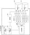
- FIG. 2is a block diagram showing a configuration of the transmission apparatus 100 according to the embodiment of the present invention.
- the transmission apparatus 100includes a wireless port 110 (or physical port), a virtual port 120, a monitoring unit 130, a virtual port control unit 140, a port number table storage unit 150, and a LAG control unit 160 (or Transmission control unit).
- the direction of the arrow in FIG. 2shows an example, and does not limit the direction of the signal between blocks.
- the wireless port 110provides data transmission with other devices via a wireless line (or physical line).
- a plurality of wireless ports 110constitute a LAG.
- the radio ports 110 “P1” and “P2”constitute a LAG.
- the parentheses after the reference signindicate the identifier of the component to which the reference sign is assigned.
- the wireless port 110 “P1”indicates the wireless port 110 with the identifier “P1”.
- the wireless port 110controls the modulation method by adaptive modulation according to the state of the wireless line.
- a modulation methodfor example, QPSK (Quadrature Shift Keying), 16QAM (Quadrature Amplitude Modulation), 64QAM, or the like is used.
- the transmission capacity of the wireless port 110depends on the modulation method. For example, when the transmission capacity by QPSK is 100 Mbps, the transmission capacity of 16 QAM is 200 Mbps, and the transmission capacity of 64 QAM is 300 Mbps.
- the virtual port 120is a virtual port for providing data transmission via the wireless port 110.
- Each virtual port 120provides data transmission with a predetermined (identical) transmission capacity.
- Each virtual port 120is assigned to one of the wireless ports 110 in advance.
- virtual ports 120 “VP1A” to “VP1C”are assigned to the wireless port 110 “P1”
- virtual ports 120 “VP2A” to “VP2C”are assigned to the wireless port 110 “P2”.
- the monitoring unit 130monitors the state of the wireless port 110. When the monitoring unit 130 detects a change of the modulation scheme in the wireless port 110, the monitoring unit 130 notifies the virtual port control unit 140 of the changed modulation scheme.
- the port number table storage unit 150stores a port number table 151.
- the port number table 151indicates the number of virtual ports 120 used for data transmission with respect to the modulation scheme.
- the number of virtual ports 120is set as large as possible so that, for example, the total value for the number of virtual ports 120 of the predetermined transmission capacity is equal to or less than the transmission capacity according to the modulation method. Is done.
- FIG. 5is a diagram showing an example of the port number table 151 in the embodiment of the present invention.
- the numbers “1”, “2”, and “3” of the virtual ports 120are set for the modulation schemes “QPSK”, “16QAM”, and “64QAM”, respectively.
- the virtual port control unit 140determines the number of virtual ports 120 used for data transmission among the virtual ports 120 allocated to the wireless port 110 according to the transmission capacity of the wireless port 110.
- the virtual port control unit 140obtains the number of virtual ports 120 corresponding to the modulation method of the wireless port 110 from the port number table 151, and thereby the number of virtual ports 120 corresponding to the transmission capacity determined by the modulation method. To decide. Then, the virtual port control unit 140 selects the determined number of virtual ports 120 among the virtual ports 120 allocated to the wireless port 110 as virtual ports 120 used for data transmission.
- the virtual port control unit 140generates virtual port information 141 indicating the usage state of each virtual port 120 and transmits the virtual port information 141 to the LAG control unit 160.
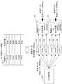
- FIGS. 6 and 7are diagrams showing an example of the distribution of the virtual port information 141 and the transmission data in the embodiment of the present invention.
- the usage status of the virtual port 120is indicated as “valid” indicating usage and “invalid” indicating that it is not used.
- the virtual port control unit 140determines the number of virtual ports 120 by a method other than the method of acquiring the number corresponding to the modulation scheme. May be.
- the virtual port control unit 140may calculate the number of virtual ports 120 by dividing the transmission capacity value acquired from the wireless port 110 by the predetermined transmission capacity value of the virtual port 120.
- the LAG control unit 160transmits the transmission data via the virtual port 120.
- the LAG control unit 160considers that the logical port of the LAG is configured by the virtual port 120 whose usage state is “valid” in the virtual port information 141. Then, the LAG control unit 160 distributes and transmits the transmission data to the virtual ports 120 whose usage state is “valid” so that the transmission rates are equal.
- the LAG control unit 160may distribute and transmit the transmission data so that the transmission rates are substantially equal (substantially equal).
- the transmission apparatus 100may be realized using a computer that includes a CPU (Central Processing Unit) and a storage medium that stores a program and that operates by control based on the program.
- a CPUCentral Processing Unit
- a storage mediumthat stores a program and that operates by control based on the program.
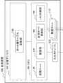
- FIG. 3is a block diagram showing a configuration of transmission apparatus 100 realized by a computer in the embodiment of the present invention.
- the transmission apparatus 100includes a CPU 101, a storage device 102 (storage medium) such as a hard disk and a memory, an input / output device 103 such as a keyboard and a display, and a wireless port 110.
- the CPU 101executes a computer program for realizing the virtual port 120, the monitoring unit 130, the virtual port control unit 140, and the LAG control unit 160.
- the storage device 102stores the data (port number table 151) of the port number table storage unit 150.
- the input / output device 103performs input from a user or the like, such as various settings related to the transmission apparatus 100, and output to the user or the like.
- each component of the transmission device 100may be an independent logic circuit.
- the transmission rate of each virtual port 120is 100 Mbps and the transmission rate of transmission data is 400 Mbps. Further, it is assumed that the port number table storage unit 150 stores the port number table 151 of FIG.
- the wireless ports 110 “P1” and “P2”have a transmission capacity of 300 Mbps (modulation method “64QAM”), and the virtual ports 120 “VP1A” to “VP1C” and “VP2A” of the virtual port information 141 Suppose that the usage status of “VP2C” is “valid”.
- the LAG control unit 160transmits 400 Mbps transmission data to the six virtual ports 120 “VP1A” to “VP1C” and “VP2A” to “VP2C” as shown in FIG. , Send evenly distributed.
- the transmission datais transmitted 200 Mbps at a time via the wireless ports 110 “P1” and “P2”.
- FIG. 4is a flowchart showing the operation of the transmission apparatus 100 in the embodiment of the present invention.
- the monitoring unit 130monitors the state of each wireless port 110 (step S101).
- the monitoring unit 130When the modulation method is changed in the wireless port 110 (step S102 / Y), the monitoring unit 130 notifies the virtual port control unit 140 of the identifier of the wireless port 110 whose modulation method has been changed and the modulation method after the change. To do.
- the monitoring unit 130when the modulation scheme of the wireless port 110 “P1” is changed from “64QAM” to “QPSK”, the monitoring unit 130 notifies the virtual port control unit 140 of the identifier “ P1 "and modulation scheme” QPSK "are notified.
- the virtual port control unit 140acquires the number of virtual ports 120 corresponding to the modulation scheme notified by the monitoring unit 130 from the port number table 151 (step S103). Then, the virtual port control unit 140 selects the determined number of virtual ports 120 among the virtual ports 120 allocated to the wireless port 110 as virtual ports 120 used for data transmission (step S104). The virtual port control unit 140 updates the virtual port information 141 according to the selection result (step S105), and transmits the updated virtual port information 141 to the LAG control unit 160.
- the virtual port control unit 140acquires the number “1” of the virtual ports 120 for the modulation scheme “QPSK” from the port number table 151 in FIG.
- the virtual port control unit 140selects, for example, the virtual port 120 “VP1C” among the virtual ports 120 “VP1A” to “VP1C” assigned to the wireless port 110 “P1”.
- the virtual port control unit 140uses “invalid” for the usage status of the virtual ports 120 “VP1A” and “VP1B” and “valid” for the usage status of the virtual port 120 “VP1C” in the virtual port information 141. Is transmitted to the LAG control unit 160.
- the LAG control unit 160distributes the transmission data to the virtual port 120 whose usage state is “valid” according to the virtual port information 141 so as to equalize the transmission rate (step S106).
- the LAG control unit 160equally distributes 400 Mbps transmission data to the four virtual ports 120 “VP1C”, “VP2A” to “VP2C” according to the virtual port information 141. Send.
- the transmission datais transmitted without being discarded at a transmission rate of 100 Mbps via the wireless port 110 “P1” and 300 Mbps via the wireless port 110 “P2”.
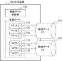
- FIG. 1is a block diagram showing a characteristic configuration of an embodiment of the present invention.
- the transmission device 100includes a plurality of virtual ports 120 and a virtual port control unit 140.
- Each of the plurality of virtual ports 120is assigned to one of a plurality of wireless ports 110 (physical ports) whose transmission capacity can be changed, and performs data transmission with a predetermined transmission capacity using the wireless port 110 of the assignment destination. provide.
- the virtual port control unit 140determines the virtual port 120 used for data transmission among the virtual ports 120 allocated to the wireless port 110 according to the transmission capacity of the wireless port 110. Determine the number.
- the transmission capacity of each physical linecan be effectively used even when the transmission capacity of the physical line constituting the link aggregation varies.
- the virtual port control unit 140 of the transmission apparatus 100provides data transmission of a predetermined transmission capacity using the wireless port 110 according to the transmission capacity of each wireless port 110. This is to determine the number of virtual ports 120 used for data transmission. As a result, the transmission data is distributed and transmitted to the determined number of virtual ports 120 so that the transmission rates are equal, so that each wireless port 110 has a transmission rate according to the transmission capacity of the wireless port 110. , Data is transmitted.
- the transmission capacity of the wireless ports 110is equal to or higher than the transmission rate of transmission data, the transmission capacity of each physical line constituting the link aggregation is used effectively, and the transmission rate does not decrease (discarding of transmission data occurs) do not do).
- the effective utilization of the transmission capacity of the physical lines constituting such link aggregationcan be easily utilized by diverting the general LAG control unit 160 that distributes transmission data. realizable.
- the reasonis that the virtual port control unit 140 selects the number of virtual ports 120 determined according to the transmission capacity of each wireless port 110 and notifies the LAG control unit 160 of it.
- the LAG control unit 160distributes the transmission data to the selected virtual port 120 instead of the radio port 110 constituting the LAG, and the transmission capacity of each physical line is effectively used.
- a physical linecan be a wired line or both a wired line and a wireless line. You may mix and use.
- Transmission device101 CPU DESCRIPTION OF SYMBOLS 102 Storage device 103 Input / output device 110 Wireless port 120 Virtual port 130 Monitoring part 140 Virtual port control part 141 Virtual port information 150 Port number table storage part 151 Port number table 160 LAG control part 900 Transmission apparatus 910 Wireless port 920 LAG control part
Landscapes
- Engineering & Computer Science (AREA)
- Computer Networks & Wireless Communication (AREA)
- Signal Processing (AREA)
- Mobile Radio Communication Systems (AREA)
Abstract
Description
Translated fromJapanese本発明は、伝送装置、伝送制御方法、及び、記録媒体に関する。The present invention relates to a transmission device, a transmission control method, and a recording medium.
伝送装置間を接続するための技術として、複数の物理回線を束ね、1つの論理回線として扱うリンクアグリゲーションが知られている。リンクアグリゲーションでは、例えば、特許文献1に開示されているように、論理回線を構成する複数の物理回線を有効的に使うために、当該複数の物理回線に送信データを均等に振り分けるアルゴリズムが使用される。As a technique for connecting between transmission apparatuses, link aggregation is known in which a plurality of physical lines are bundled and handled as one logical line. In link aggregation, for example, as disclosed in
無線通信では外部環境に応じた最適な変調方式を選択する方法として、適応変調(Adaptive Modulation)が用いられることがある。適応変調により無線ポートの変調方式が変更されると、利用可能な帯域である伝送容量が変動し、無線ポート間に伝送容量の差が生じる。このような無線通信にリンクアグリゲーションが適用され、上述の、送信データを均等に振り分けるアルゴリズムが用いられた場合、論理ポートを構成する各無線ポートの伝送容量をフルに使用することができず、送信データが廃棄される可能性がある。In wireless communication, adaptive modulation may be used as a method for selecting an optimal modulation method according to the external environment. When the modulation method of the wireless port is changed by adaptive modulation, the transmission capacity that is an available band fluctuates, and a difference in transmission capacity occurs between the wireless ports. When link aggregation is applied to such wireless communication and the above-described algorithm for equally distributing transmission data is used, the transmission capacity of each wireless port constituting the logical port cannot be fully used, and transmission is performed. Data may be discarded.
図8、図9は、このような、一般的な無線通信における、リンクアグリゲーションの例を示す図である。図8、図9の例では、伝送装置900は、無線ポート910「P1」、「P2」、及び、LAG(Link Aggregation Group)制御部920を含む。無線ポート910「P1」、「P2」は、LAGの論理ポートを構成する。無線ポート910は、適応変調により、変調方式を制御する。LAG制御部920は、送信データを、論理ポートを構成する無線ポート910「P1」、「P2」に均等に振り分ける。8 and 9 are diagrams showing examples of link aggregation in such general wireless communication. 8 and 9, the transmission apparatus 900 includes
例えば、図8、図9において、送信データの伝送レートが400Mbpsの場合、LAG制御部920は、送信データを、無線ポート910「P1」、「P2」に200Mbpsずつ振り分ける。For example, in FIGS. 8 and 9, when the transmission rate of the transmission data is 400 Mbps, the
ここで、例えば、図8のように、無線ポート910「P1」、「P2」の伝送容量が、同一の300Mbpsである場合、無線ポート910「P1」、「P2」に振り分けられた200Mbpsの送信データは、正常に伝送される。一方、例えば、図9のように、適応変調により無線ポート910「P1」の伝送容量が100Mbpsに変動した場合、無線ポート910「P1」に振り分けられた200Mbpsの送信データの内、100Mbpsの送信データは廃棄される。Here, for example, as shown in FIG. 8, when the transmission capacities of the
このように、無線通信におけるリンクアグリゲーションでは、物理回線の伝送容量が変動した場合に、物理回線の伝送容量の合計が送信データの伝送レート以上であっても、各物理回線の伝送容量が有効に利用されず、伝送レートが低下するという課題がある。In this way, in link aggregation in wireless communication, when the transmission capacity of a physical line fluctuates, the transmission capacity of each physical line is effective even if the total transmission capacity of the physical line is equal to or higher than the transmission rate of the transmission data. There is a problem that the transmission rate is not used and the transmission rate is lowered.
なお、特許文献2には、関連技術として、無線通信におけるリンクアグリゲーションにおいて、無線リンクの変調方式に係る帯域の安定度と、パスの優先度毎のトラヒックパターンをもとに、トラヒックが使用する無線リンクを決定する方法が開示されている。Note that
上述のように、特許文献1に記載されているようなリンクアグリゲーションでは、リンクアグリゲーションを構成する物理回線の伝送容量が変動する場合に、各物理回線の伝送容量を有効に利用できないという課題があった。As described above, the link aggregation described in
本発明の目的は、上述の課題を解決し、リンクアグリゲーションを構成する物理回線の伝送容量が変動する場合でも、各物理回線の伝送容量を有効利用できる、伝送装置、伝送制御方法、及び、記録媒体を提供することである。An object of the present invention is to solve the above-described problems and to enable effective use of the transmission capacity of each physical line even when the transmission capacity of the physical line constituting the link aggregation fluctuates, a transmission apparatus, a transmission control method, and a recording To provide a medium.
本発明の伝送装置は、各々が、伝送容量が変更可能な複数の物理ポートのいずれかに割り当てられ、当該割り当て先の物理ポートを用いた、所定の伝送容量のデータ伝送を提供する複数の仮想ポートと、前記複数の物理ポートの各々について、当該物理ポートの伝送容量に応じて、当該物理ポートに割り当てられた仮想ポートの内の、データ伝送に用いる仮想ポートの数を決定する、仮想ポート制御手段と、を備える。The transmission apparatus according to the present invention includes a plurality of virtual devices each of which is assigned to one of a plurality of physical ports whose transmission capacity can be changed and provides data transmission with a predetermined transmission capacity using the physical port of the assignment destination. Virtual port control for determining the number of virtual ports to be used for data transmission among the virtual ports assigned to the physical port according to the transmission capacity of the physical port for each of the plurality of physical ports Means.
本発明の伝送制御方法は、伝送容量が変更可能な複数の物理ポートの各々について、当該物理ポートの伝送容量に応じて、当該物理ポートを用いた所定の伝送容量のデータ伝送を提供する仮想ポートであって、当該物理ポートに割り当てられた仮想ポートの内の、データ伝送に用いる仮想ポートの数を決定する。According to the transmission control method of the present invention, for each of a plurality of physical ports whose transmission capacity can be changed, a virtual port that provides data transmission of a predetermined transmission capacity using the physical port according to the transmission capacity of the physical port Then, the number of virtual ports used for data transmission among the virtual ports assigned to the physical port is determined.
本発明のコンピュータが読み取り可能な記録媒体は、コンピュータに、伝送容量が変更可能な複数の物理ポートの各々を監視し、前記複数の物理ポートの各々について、当該物理ポートの伝送容量に応じて、当該物理ポートを用いた所定の伝送容量のデータ伝送を提供する仮想ポートであって、当該物理ポートに割り当てられた仮想ポートの内の、データ伝送に用いる仮想ポートの数を決定する、処理を実行させるプログラムを格納する。According to the computer-readable recording medium of the present invention, the computer monitors each of the plurality of physical ports whose transmission capacity can be changed, and for each of the plurality of physical ports, according to the transmission capacity of the physical port, A virtual port that provides data transmission of a predetermined transmission capacity using the physical port, and determines the number of virtual ports used for data transmission among the virtual ports assigned to the physical port. Store the program to be executed.
本発明の効果は、リンクアグリゲーションを構成する物理回線の伝送容量が変動する場合でも、物理回線の伝送容量を有効利用できることである。The effect of the present invention is that the transmission capacity of the physical line can be effectively used even when the transmission capacity of the physical line constituting the link aggregation varies.
はじめに、本発明の実施の形態の構成を説明する。本発明の実施の形態では、伝送装置100が、他の装置との間で無線回線により通信(データ伝送)を行う、無線装置である場合を例に説明する。伝送装置100は、例えば、モバイルバックホールで用いられる、マイクロ波通信装置や、ミリ波通信装置でもよい。First, the configuration of the embodiment of the present invention will be described. In the embodiment of the present invention, a case where the transmission apparatus 100 is a wireless apparatus that performs communication (data transmission) with another apparatus via a wireless line will be described as an example. The transmission device 100 may be, for example, a microwave communication device or a millimeter wave communication device used in a mobile backhaul.
図2は、本発明の実施の形態における、伝送装置100の構成を示すブロック図である。図2を参照すると、伝送装置100は、無線ポート110(または、物理ポート)、仮想ポート120、監視部130、仮想ポート制御部140、ポート数テーブル記憶部150、及び、LAG制御部160(または、送信制御部)を含む。なお、図2における矢印の方向は、一例を示すものであり、ブロック間の信号の向きを限定するものではない。FIG. 2 is a block diagram showing a configuration of the transmission apparatus 100 according to the embodiment of the present invention. Referring to FIG. 2, the transmission apparatus 100 includes a wireless port 110 (or physical port), a
無線ポート110は、無線回線(または、物理回線)による他の装置との間のデータ伝送を提供する。複数の無線ポート110が、LAGを構成する。The
図2の例では、無線ポート110「P1」、「P2」がLAGを構成する。なお、本発明の実施の形態において、符号の後の括弧内は、当該符号が付与された構成要素の識別子を示す。例えば、無線ポート110「P1」は、識別子「P1」の無線ポート110を示す。In the example of FIG. 2, the
また、無線ポート110は、無線回線の状態に応じて、適応変調により変調方式を制御する。変調方式としては、例えば、QPSK(Quadrature Phase Shift Keying)、16QAM(Quadrature Amplitude Modulation)、64QAM等が用いられる。無線ポート110の伝送容量は、変調方式に依存する。例えば、QPSKによる伝送容量が100Mbpsの場合、16QAMの伝送容量は200Mbps、64QAMの伝送容量は300Mbpsである。Also, the
仮想ポート120は、無線ポート110を介したデータ伝送を提供するための仮想的なポートである。各仮想ポート120は、所定の(同一の)伝送容量によるデータ伝送を提供する。各仮想ポート120は、予め、無線ポート110のいずれかに割り当てられる。The
図2の例では、仮想ポート120「VP1A」~「VP1C」が無線ポート110「P1」に割り当てられ、仮想ポート120「VP2A」~「VP2C」が無線ポート110「P2」に割り当てられている。In the example of FIG. 2,
監視部130は、無線ポート110の状態を監視する。監視部130は、無線ポート110における変調方式の変更を検出した場合、仮想ポート制御部140に、変更後の変調方式を通知する。The
ポート数テーブル記憶部150は、ポート数テーブル151を記憶する。ポート数テーブル151は、変調方式に対して、データ伝送に利用する仮想ポート120の数を示す。ここで、仮想ポート120の数には、例えば、上述の所定の伝送容量の当該仮想ポート120の数分の合計値が、変調方式に応じた伝送容量以下となるような、できるだけ大きい数が設定される。The port number
図5は、本発明の実施の形態における、ポート数テーブル151の例を示す図である。図5の例では、変調方式「QPSK」、「16QAM」、「64QAM」に対して、それぞれ、仮想ポート120の数「1」、「2」、「3」が設定されている。FIG. 5 is a diagram showing an example of the port number table 151 in the embodiment of the present invention. In the example of FIG. 5, the numbers “1”, “2”, and “3” of the
仮想ポート制御部140は、無線ポート110の伝送容量に応じて、当該無線ポート110に割り当てられた仮想ポート120の内の、データ伝送に用いる仮想ポート120の数を決定する。ここで、仮想ポート制御部140は、ポート数テーブル151から、無線ポート110の変調方式に対応する仮想ポート120の数を取得することにより、変調方式により決まる伝送容量に応じた仮想ポート120の数を決定する。そして、仮想ポート制御部140は、無線ポート110に割り当てられた仮想ポート120の内、決定した数分の仮想ポート120を、データ伝送に利用する仮想ポート120として選択する。仮想ポート制御部140は、各仮想ポート120の利用状態を示す仮想ポート情報141を生成し、LAG制御部160に送信する。The virtual
図6、及び、図7は、本発明の実施の形態における、仮想ポート情報141と送信データの振り分けの例を示す図である。仮想ポート情報141では、各仮想ポート120の識別子に対して、当該仮想ポート120の利用状態が、利用を表す「有効」、利用していないことを表す「無効」で示されている。6 and 7 are diagrams showing an example of the distribution of the virtual port information 141 and the transmission data in the embodiment of the present invention. In the virtual port information 141, for each
なお、仮想ポート制御部140は、無線ポート110の伝送容量に応じた仮想ポート120の数を決定できれば、変調方式に対応する数を取得する方法以外の方法で、仮想ポート120の数を決定してもよい。例えば、仮想ポート制御部140は、無線ポート110から取得した伝送容量の値を、仮想ポート120の所定の伝送容量の値で割ることにより、仮想ポート120の数を算出してもよい。Note that if the virtual
LAG制御部160は、送信データを、仮想ポート120を介して送信する。ここで、LAG制御部160は、LAGの論理ポートが、仮想ポート情報141において利用状態が「有効」である仮想ポート120により構成されるとみなす。そして、LAG制御部160は、送信データを、これら利用状態が「有効」である仮想ポート120に、伝送レートが均等になるように振り分けて送信する。ここで、LAG制御部160は、送信データを、伝送レートがほぼ均等(略均等)になるように振り分けて送信してもよい。The
なお、伝送装置100は、CPU(Central Processing Unit)とプログラムを記憶した記憶媒体を含み、プログラムに基づく制御によって動作するコンピュータを用いて実現されていてもよい。Note that the transmission apparatus 100 may be realized using a computer that includes a CPU (Central Processing Unit) and a storage medium that stores a program and that operates by control based on the program.
図3は、本発明の実施の形態における、コンピュータにより実現された伝送装置100の構成を示すブロック図である。FIG. 3 is a block diagram showing a configuration of transmission apparatus 100 realized by a computer in the embodiment of the present invention.
この場合、伝送装置100は、CPU101、ハードディスクやメモリ等の記憶デバイス102(記憶媒体)、キーボード、ディスプレイ等の入出力デバイス103、及び、無線ポート110を含む。CPU101は、仮想ポート120、監視部130、仮想ポート制御部140、及び、LAG制御部160を実現するためのコンピュータプログラムを実行する。記憶デバイス102は、ポート数テーブル記憶部150のデータ(ポート数テーブル151)を記憶する。入出力デバイス103は、伝送装置100に係る各種設定等の、ユーザ等からの入力、及び、ユーザ等への出力を行う。In this case, the transmission apparatus 100 includes a
また、伝送装置100の各構成要素は、独立した論理回路でもよい。Further, each component of the transmission device 100 may be an independent logic circuit.
次に、本発明の実施の形態の動作を説明する。Next, the operation of the embodiment of the present invention will be described.
ここでは、図2の伝送装置100において、各仮想ポート120の伝送レートが100Mbps、送信データの伝送レートが400Mbpsであると仮定する。また、ポート数テーブル記憶部150には、図5のポート数テーブル151が格納されていると仮定する。Here, in the transmission apparatus 100 of FIG. 2, it is assumed that the transmission rate of each
また、図6のように、無線ポート110「P1」、「P2」の伝送容量が300Mbps(変調方式「64QAM」)、仮想ポート情報141の仮想ポート120「VP1A」~「VP1C」、「VP2A」~「VP2C」の利用状態が「有効」であると仮定する。この場合、LAG制御部160は、仮想ポート情報141に従って、図6に示すように、400Mbpsの送信データを、6個の仮想ポート120「VP1A」~「VP1C」、「VP2A」~「VP2C」に、均等に振り分けて送信する。これにより、送信データは、無線ポート110「P1」、「P2」を介して、200Mbpsずつ送信される。Further, as shown in FIG. 6, the
図4は、本発明の実施の形態における、伝送装置100の動作を示すフローチャートである。FIG. 4 is a flowchart showing the operation of the transmission apparatus 100 in the embodiment of the present invention.
はじめに、監視部130は、各無線ポート110の状態を監視する(ステップS101)。First, the
無線ポート110において変調方式が変更された場合(ステップS102/Y)、監視部130は、仮想ポート制御部140に、変調方式が変更された無線ポート110の識別子と変更後の変調方式とを通知する。When the modulation method is changed in the wireless port 110 (step S102 / Y), the
例えば、図7に示すように、無線ポート110「P1」の変調方式が「64QAM」から「QPSK」に変更された場合、監視部130は、仮想ポート制御部140に、無線ポート110の識別子「P1」と変調方式「QPSK」とを通知する。For example, as illustrated in FIG. 7, when the modulation scheme of the
仮想ポート制御部140は、ポート数テーブル151から、監視部130により通知された変調方式に対する仮想ポート120の数を取得する(ステップS103)。そして、仮想ポート制御部140は、無線ポート110に割り当てられた仮想ポート120の内、決定した数分の仮想ポート120を、データ伝送に利用する仮想ポート120として選択する(ステップS104)。仮想ポート制御部140は、選択結果に従って、仮想ポート情報141を更新し(ステップS105)、更新した仮想ポート情報141をLAG制御部160に送信する。The virtual
例えば、仮想ポート制御部140は、図5のポート数テーブル151から、変調方式「QPSK」に対する仮想ポート120の数「1」を取得する。仮想ポート制御部140は、無線ポート110「P1」に割り当てられた仮想ポート120「VP1A」~「VP1C」の内、例えば、仮想ポート120「VP1C」を選択する。仮想ポート制御部140は、図7に示すように、仮想ポート情報141において、仮想ポート120「VP1A」、「VP1B」の利用状態に「無効」、仮想ポート120「VP1C」の利用状態に「有効」を設定し、LAG制御部160に送信する。For example, the virtual
LAG制御部160は、仮想ポート情報141に従って、利用状態が「有効」である仮想ポート120に、送信データを、伝送レートが均等になるように振り分けて送信する(ステップS106)。The
例えば、LAG制御部160は、図7に示すように、仮想ポート情報141に従って、400Mbpsの送信データを、4個の仮想ポート120「VP1C」、「VP2A」~「VP2C」に、均等に振り分けて送信する。これにより、送信データは、無線ポート110「P1」を介して100Mbps、無線ポート110「P2」を介して300Mbpsの伝送レートで、廃棄されることなく送信される。For example, as shown in FIG. 7, the
以上により、本発明の実施の形態の動作が完了する。Thus, the operation of the embodiment of the present invention is completed.
次に、本発明の実施の形態の特徴的な構成を説明する。図1は、本発明の実施の形態の特徴的な構成を示すブロック図である。Next, a characteristic configuration of the embodiment of the present invention will be described. FIG. 1 is a block diagram showing a characteristic configuration of an embodiment of the present invention.
図1を参照すると、伝送装置100は、複数の仮想ポート120、及び、仮想ポート制御部140を含む。複数の仮想ポート120の各々は、伝送容量が変更可能な複数の無線ポート110(物理ポート)のいずれかに割り当てられ、当該割り当て先の無線ポート110を用いた、所定の伝送容量のデータ伝送を提供する。仮想ポート制御部140は、複数の無線ポート110の各々について、当該無線ポート110の伝送容量に応じて、当該無線ポート110に割り当てられた仮想ポート120の内の、データ伝送に用いる仮想ポート120の数を決定する。Referring to FIG. 1, the transmission device 100 includes a plurality of
次に、本発明の実施の形態の効果を説明する。Next, the effect of the embodiment of the present invention will be described.
本発明の実施の形態によれば、リンクアグリゲーションを構成する物理回線の伝送容量が変動する場合でも、各物理回線の伝送容量を有効利用できる。その理由は、伝送装置100の仮想ポート制御部140が、各無線ポート110の伝送容量に応じて、当該無線ポート110を用いた所定の伝送容量のデータ伝送を提供する仮想ポート120の内の、データ伝送に用いる仮想ポート120の数を決定するためである。これにより、決定した数の仮想ポート120に、伝送レートが均等になるように送信データを振り分けて送信することで、各無線ポート110からは、当該無線ポート110の伝送容量に応じた伝送レートで、データが送信される。したがって、無線ポート110の伝送容量の合計が送信データの伝送レート以上であれば、リンクアグリゲーションを構成する各物理回線の伝送容量が有効に利用され、伝送レートは低下しない(送信データの廃棄は発生しない)。According to the embodiment of the present invention, the transmission capacity of each physical line can be effectively used even when the transmission capacity of the physical line constituting the link aggregation varies. The reason is that the virtual
また、本発明の実施の形態によれば、このようなリンクアグリゲーションを構成する物理回線の伝送容量の有効利用を、送信データの振り分けを行う一般的なLAG制御部160を流用して、容易に実現できる。その理由は、仮想ポート制御部140が、各無線ポート110の伝送容量に応じて決定した数の仮想ポート120を選択し、LAG制御部160に通知するためである。LAG制御部160は、LAGを構成する無線ポート110の代わりに、選択された仮想ポート120に送信データを振り分けるだけで、各物理回線の伝送容量が有効に利用される。Further, according to the embodiment of the present invention, the effective utilization of the transmission capacity of the physical lines constituting such link aggregation can be easily utilized by diverting the general
以上、実施形態を参照して本願発明を説明したが、本願発明は上記実施形態に限定されるものではない。本願発明の構成や詳細には、本願発明のスコープ内で当業者が理解し得る様々な変更をすることができる。The present invention has been described above with reference to the embodiments, but the present invention is not limited to the above embodiments. Various changes that can be understood by those skilled in the art can be made to the configuration and details of the present invention within the scope of the present invention.
例えば、本発明の実施の形態では、物理回線が無線回線である場合を例に説明したが、伝送容量を変更可能であれば、物理回線として、有線回線や、有線回線と無線回線の両方を混在して用いてもよい。For example, in the embodiment of the present invention, the case where the physical line is a wireless line has been described as an example. However, if the transmission capacity can be changed, a physical line can be a wired line or both a wired line and a wireless line. You may mix and use.
この出願は、2015年8月3日に出願された日本出願特願2015-153537を基礎とする優先権を主張し、その開示の全てをここに取り込む。This application claims priority based on Japanese Patent Application No. 2015-153537 filed on August 3, 2015, the entire disclosure of which is incorporated herein.
100 伝送装置
101 CPU
102 記憶デバイス
103 入出力デバイス
110 無線ポート
120 仮想ポート
130 監視部
140 仮想ポート制御部
141 仮想ポート情報
150 ポート数テーブル記憶部
151 ポート数テーブル
160 LAG制御部
900 伝送装置
910 無線ポート
920 LAG制御部100
DESCRIPTION OF SYMBOLS 102
Claims (10)
Translated fromJapanese前記複数の物理ポートの各々について、当該物理ポートの伝送容量に応じて、当該物理ポートに割り当てられた仮想ポートの内の、データ伝送に用いる仮想ポートの数を決定する、仮想ポート制御手段と、
を備えた、伝送装置。A plurality of virtual ports each of which is assigned to one of a plurality of physical ports whose transmission capacity can be changed, and which provides data transmission of a predetermined transmission capacity using the physical port of the assignment destination;
Virtual port control means for determining the number of virtual ports used for data transmission among the virtual ports assigned to the physical port, for each of the plurality of physical ports, according to the transmission capacity of the physical port;
A transmission device comprising:
さらに、送信データを、前記選択された仮想ポートに、伝送レートが略均等になるように振り分けて送信する、送信制御手段を備えた、
請求項1に記載の伝送装置。The virtual port control means selects the determined number of virtual ports among virtual ports assigned to each of the plurality of physical ports as virtual ports used for data transmission,
Furthermore, transmission data is provided to the selected virtual port so that the transmission rate is distributed so that the transmission rate is substantially equal.
The transmission apparatus according to claim 1.
請求項1または2に記載の伝送装置。The virtual port control means is configured so that, for each of the plurality of physical ports, the total value of the number of virtual ports used for the data transmission of the predetermined transmission capacity is equal to or less than the transmission capacity of the physical port. Determine the number of virtual ports used for data transmission,
The transmission apparatus according to claim 1 or 2.
請求項1乃至3のいずれかに記載の伝送装置。The virtual port control means determines the number of virtual ports used for the data transmission according to the modulation method of each of the plurality of physical ports.
The transmission apparatus according to claim 1.
伝送制御方法。For each of a plurality of physical ports whose transmission capacity can be changed, a virtual port that provides data transmission of a predetermined transmission capacity using the physical port according to the transmission capacity of the physical port, Determine the number of virtual ports used for data transmission among the allocated virtual ports.
Transmission control method.
送信データを、前記選択された仮想ポートに、伝送レートが略均等になるように振り分けて送信する、
請求項5に記載の伝送制御方法。Further, the determined number of virtual ports among the virtual ports assigned to each of the plurality of physical ports is selected as a virtual port used for data transmission,
The transmission data is distributed and transmitted to the selected virtual port so that the transmission rate is substantially equal.
The transmission control method according to claim 5.
請求項5または6に記載の伝送制御方法。When determining the number of virtual ports used for the data transmission, for each of the plurality of physical ports, the total value for the number of virtual ports used for the data transmission of the predetermined transmission capacity is the transmission capacity of the physical port. Determine the number of virtual ports used for the data transmission, as follows:
The transmission control method according to claim 5 or 6.
請求項5乃至7のいずれかに記載の伝送制御方法。When determining the number of virtual ports used for the data transmission, the number of virtual ports used for the data transmission is determined according to the modulation scheme of each of the plurality of physical ports.
The transmission control method according to claim 5.
伝送容量が変更可能な複数の物理ポートの各々を監視し、
前記複数の物理ポートの各々について、当該物理ポートの伝送容量に応じて、当該物理ポートを用いた所定の伝送容量のデータ伝送を提供する仮想ポートであって、当該物理ポートに割り当てられた仮想ポートの内の、データ伝送に用いる仮想ポートの数を決定する、
処理を実行させるプログラムを格納する、コンピュータが読み取り可能な記録媒体。On the computer,
Monitor each of the multiple physical ports whose transmission capacity can be changed,
For each of the plurality of physical ports, a virtual port that provides data transmission with a predetermined transmission capacity using the physical port according to the transmission capacity of the physical port, and the virtual port assigned to the physical port Determining the number of virtual ports used for data transmission,
A computer-readable recording medium storing a program for executing processing.
送信データを、前記選択された仮想ポートに、伝送レートが略均等になるように振り分けて送信する、
処理を実行させる請求項9に記載のプログラムを格納する、コンピュータが読み取り可能な記録媒体。Further, the determined number of virtual ports among the virtual ports assigned to each of the plurality of physical ports is selected as a virtual port used for data transmission,
The transmission data is distributed and transmitted to the selected virtual port so that the transmission rate is substantially equal.
A computer-readable recording medium storing the program according to claim 9 for executing processing.
Priority Applications (1)
| Application Number | Priority Date | Filing Date | Title |
|---|---|---|---|
| US15/746,118US20180213462A1 (en) | 2015-08-03 | 2016-08-02 | Transmission device, transmission control method, and recording medium |
Applications Claiming Priority (2)
| Application Number | Priority Date | Filing Date | Title |
|---|---|---|---|
| JP2015-153537 | 2015-08-03 | ||
| JP2015153537 | 2015-08-03 |
Publications (1)
| Publication Number | Publication Date |
|---|---|
| WO2017022235A1true WO2017022235A1 (en) | 2017-02-09 |
Family
ID=57942718
Family Applications (1)
| Application Number | Title | Priority Date | Filing Date |
|---|---|---|---|
| PCT/JP2016/003543CeasedWO2017022235A1 (en) | 2015-08-03 | 2016-08-02 | Transmission device, transmission control method, and recording medium |
Country Status (2)
| Country | Link |
|---|---|
| US (1) | US20180213462A1 (en) |
| WO (1) | WO2017022235A1 (en) |
Cited By (2)
| Publication number | Priority date | Publication date | Assignee | Title |
|---|---|---|---|---|
| CN115552819A (en)* | 2020-05-06 | 2022-12-30 | 质一科技有限公司 | Virtual network device |
| JP2023523687A (en)* | 2020-04-02 | 2023-06-07 | プライムワン リミテッド | Device, method and system for virtualizing networks |
Citations (2)
| Publication number | Priority date | Publication date | Assignee | Title |
|---|---|---|---|---|
| JP2014107650A (en)* | 2012-11-27 | 2014-06-09 | Nippon Telegr & Teleph Corp <Ntt> | Device and program for detecting link aggregation failure |
| JP2014138365A (en)* | 2013-01-18 | 2014-07-28 | Nec Corp | Network system, communication control method and communication control program |
Family Cites Families (16)
| Publication number | Priority date | Publication date | Assignee | Title |
|---|---|---|---|---|
| US7315554B2 (en)* | 2000-08-31 | 2008-01-01 | Verizon Communications Inc. | Simple peering in a transport network employing novel edge devices |
| JP4389605B2 (en)* | 2004-02-26 | 2009-12-24 | 日本電気株式会社 | Multicast information distribution system and multicast information distribution method |
| JP2006005437A (en)* | 2004-06-15 | 2006-01-05 | Fujitsu Ltd | Traffic distribution control device |
| JP5086585B2 (en)* | 2006-08-11 | 2012-11-28 | アラクサラネットワークス株式会社 | Network relay device |
| JP4757165B2 (en)* | 2006-10-04 | 2011-08-24 | 株式会社日立製作所 | Computer system, data migration monitoring method, and data migration monitoring program |
| JP4862743B2 (en)* | 2007-05-17 | 2012-01-25 | 日本電気株式会社 | Node, communication method and node program |
| CN103138819B (en)* | 2007-08-17 | 2017-07-07 | 太阳专利信托公司 | Base station device, terminal device, integrated circuit, and transmission and reception method |
| JP5072692B2 (en)* | 2008-04-07 | 2012-11-14 | 株式会社日立製作所 | Storage system with multiple storage system modules |
| US8982851B2 (en)* | 2009-01-06 | 2015-03-17 | Qualcomm Incorporated | Hearability improvements for reference signals |
| US8370835B2 (en)* | 2009-03-12 | 2013-02-05 | Arend Erich Dittmer | Method for dynamically generating a configuration for a virtual machine with a virtual hard disk in an external storage device |
| US8260986B2 (en)* | 2009-09-29 | 2012-09-04 | Hitachi, Ltd. | Methods and apparatus for managing virtual ports and logical units on storage systems |
| JP5527419B2 (en)* | 2010-10-04 | 2014-06-18 | 富士通株式会社 | Storage system |
| US20120275450A1 (en)* | 2011-04-29 | 2012-11-01 | Comcast Cable Communications, Llc | Obtaining Services Through a Local Network |
| WO2013005245A1 (en)* | 2011-07-01 | 2013-01-10 | Hitachi, Ltd. | Storage system and controlling method of the same |
| JP5593517B2 (en)* | 2011-07-15 | 2014-09-24 | 株式会社日立製作所 | Network apparatus and transmission frame control method |
| US9621968B2 (en)* | 2013-11-11 | 2017-04-11 | Infinera Corporation | Multi layer, multi vendor, multi domain, applications for software defined networking enabled networks |
- 2016
- 2016-08-02WOPCT/JP2016/003543patent/WO2017022235A1/ennot_activeCeased
- 2016-08-02USUS15/746,118patent/US20180213462A1/ennot_activeAbandoned
Patent Citations (2)
| Publication number | Priority date | Publication date | Assignee | Title |
|---|---|---|---|---|
| JP2014107650A (en)* | 2012-11-27 | 2014-06-09 | Nippon Telegr & Teleph Corp <Ntt> | Device and program for detecting link aggregation failure |
| JP2014138365A (en)* | 2013-01-18 | 2014-07-28 | Nec Corp | Network system, communication control method and communication control program |
Non-Patent Citations (1)
| Title |
|---|
| HUAWEI: "Further consideration of Rediated Transmit Power and Its Accuracy", 3GPP TSG-RAN WG4 MEETING #68BIS R4-134898, 3GPP, XP050720423* |
Cited By (5)
| Publication number | Priority date | Publication date | Assignee | Title |
|---|---|---|---|---|
| JP2023523687A (en)* | 2020-04-02 | 2023-06-07 | プライムワン リミテッド | Device, method and system for virtualizing networks |
| JP7574312B2 (en) | 2020-04-02 | 2024-10-28 | プライムワン リミテッド | Network device, network device operation method, network system and computer-readable storage medium |
| JP2025028829A (en)* | 2020-04-02 | 2025-03-05 | プライムワン リミテッド | Device, method and system for virtualizing a network |
| JP7742921B2 (en) | 2020-04-02 | 2025-09-22 | プライムワン リミテッド | Device, method and system for virtualizing a network |
| CN115552819A (en)* | 2020-05-06 | 2022-12-30 | 质一科技有限公司 | Virtual network device |
Also Published As
| Publication number | Publication date |
|---|---|
| US20180213462A1 (en) | 2018-07-26 |
Similar Documents
| Publication | Publication Date | Title |
|---|---|---|
| CN109302268B (en) | A channel quality indication and modulation coding scheme notification method and device | |
| CN114145003B (en) | Enables data exchange between first and second communication networks having different data communication capabilities | |
| CN104796347A (en) | Load balancing method, device and system | |
| EP2922249B1 (en) | Control plane optimization of communication networks | |
| CN107995108A (en) | Network path optimization method and SDN controllers | |
| JPWO2008114351A1 (en) | Base station, radio control apparatus, radio apparatus, and data transfer method | |
| JPWO2013001732A1 (en) | Wireless transmission system, wireless transmission device, wireless transmission method, and wireless transmission program | |
| WO2019100859A1 (en) | Data transmission method and apparatus, and computer storage medium | |
| JP2017539173A (en) | Crossboard transfer method and apparatus, program, and recording medium | |
| JP7267288B2 (en) | Methods and apparatus and computer readable storage media for directing and determining information | |
| CN109392013A (en) | A kind of method of adjustment and communication device of service quality QoS | |
| CN116389947A (en) | Dynamic service-oriented bandwidth and key distribution method and related device | |
| US9247569B2 (en) | Management and optimization of wireless communications multiplexed over multiple layer-three transports with indefinite duration layer-two sessions | |
| WO2017022235A1 (en) | Transmission device, transmission control method, and recording medium | |
| CN104158683A (en) | Cross-device aggregation group rapid convergence method, and cross-device aggregation group rapid convergence device | |
| JP6662375B2 (en) | Parameter determining device, parameter determining method, and program | |
| CN106982238A (en) | A kind of method, policy control center and main frame for distributing network path resource | |
| EP3024200B1 (en) | Port number extension method and switch | |
| TWI744585B (en) | Data transmission method and device, computer storage medium | |
| CN107409132B (en) | Method and network node for dynamically configuring flow segmentation by software defined network control signaling | |
| JP5372057B2 (en) | Communication system and communication method | |
| US9100945B2 (en) | Communication node apparatus, communication system, and method for selecting destination reception interface used therefor | |
| WO2023208125A1 (en) | Terminal transmitter state determination method, system, base station and terminal | |
| US10965585B2 (en) | Method for transmitting path load information and network node | |
| CN116193609A (en) | A sidelink configuration method, network side equipment, terminal and medium |
Legal Events
| Date | Code | Title | Description |
|---|---|---|---|
| 121 | Ep: the epo has been informed by wipo that ep was designated in this application | Ref document number:16832518 Country of ref document:EP Kind code of ref document:A1 | |
| WWE | Wipo information: entry into national phase | Ref document number:15746118 Country of ref document:US | |
| NENP | Non-entry into the national phase | Ref country code:DE | |
| 122 | Ep: pct application non-entry in european phase | Ref document number:16832518 Country of ref document:EP Kind code of ref document:A1 | |
| NENP | Non-entry into the national phase | Ref country code:JP |