WO2017014473A1 - Battery pack and vehicle comprising same - Google Patents
Battery pack and vehicle comprising sameDownload PDFInfo
- Publication number
- WO2017014473A1 WO2017014473A1PCT/KR2016/007526KR2016007526WWO2017014473A1WO 2017014473 A1WO2017014473 A1WO 2017014473A1KR 2016007526 WKR2016007526 WKR 2016007526WWO 2017014473 A1WO2017014473 A1WO 2017014473A1
- Authority
- WO
- WIPO (PCT)
- Prior art keywords
- terminal
- pack
- battery
- insert
- cover
- Prior art date
- Legal status (The legal status is an assumption and is not a legal conclusion. Google has not performed a legal analysis and makes no representation as to the accuracy of the status listed.)
- Ceased
Links
Images


Classifications
- B—PERFORMING OPERATIONS; TRANSPORTING
- B60—VEHICLES IN GENERAL
- B60L—PROPULSION OF ELECTRICALLY-PROPELLED VEHICLES; SUPPLYING ELECTRIC POWER FOR AUXILIARY EQUIPMENT OF ELECTRICALLY-PROPELLED VEHICLES; ELECTRODYNAMIC BRAKE SYSTEMS FOR VEHICLES IN GENERAL; MAGNETIC SUSPENSION OR LEVITATION FOR VEHICLES; MONITORING OPERATING VARIABLES OF ELECTRICALLY-PROPELLED VEHICLES; ELECTRIC SAFETY DEVICES FOR ELECTRICALLY-PROPELLED VEHICLES
- B60L50/00—Electric propulsion with power supplied within the vehicle
- B60L50/50—Electric propulsion with power supplied within the vehicle using propulsion power supplied by batteries or fuel cells
- B60L50/60—Electric propulsion with power supplied within the vehicle using propulsion power supplied by batteries or fuel cells using power supplied by batteries
- H—ELECTRICITY
- H01—ELECTRIC ELEMENTS
- H01M—PROCESSES OR MEANS, e.g. BATTERIES, FOR THE DIRECT CONVERSION OF CHEMICAL ENERGY INTO ELECTRICAL ENERGY
- H01M10/00—Secondary cells; Manufacture thereof
- H01M10/42—Methods or arrangements for servicing or maintenance of secondary cells or secondary half-cells
- H01M10/425—Structural combination with electronic components, e.g. electronic circuits integrated to the outside of the casing
- H—ELECTRICITY
- H01—ELECTRIC ELEMENTS
- H01M—PROCESSES OR MEANS, e.g. BATTERIES, FOR THE DIRECT CONVERSION OF CHEMICAL ENERGY INTO ELECTRICAL ENERGY
- H01M50/00—Constructional details or processes of manufacture of the non-active parts of electrochemical cells other than fuel cells, e.g. hybrid cells
- H01M50/20—Mountings; Secondary casings or frames; Racks, modules or packs; Suspension devices; Shock absorbers; Transport or carrying devices; Holders
- H01M50/204—Racks, modules or packs for multiple batteries or multiple cells
- H01M50/207—Racks, modules or packs for multiple batteries or multiple cells characterised by their shape
- H01M50/209—Racks, modules or packs for multiple batteries or multiple cells characterised by their shape adapted for prismatic or rectangular cells
- H—ELECTRICITY
- H01—ELECTRIC ELEMENTS
- H01M—PROCESSES OR MEANS, e.g. BATTERIES, FOR THE DIRECT CONVERSION OF CHEMICAL ENERGY INTO ELECTRICAL ENERGY
- H01M50/00—Constructional details or processes of manufacture of the non-active parts of electrochemical cells other than fuel cells, e.g. hybrid cells
- H01M50/20—Mountings; Secondary casings or frames; Racks, modules or packs; Suspension devices; Shock absorbers; Transport or carrying devices; Holders
- H01M50/249—Mountings; Secondary casings or frames; Racks, modules or packs; Suspension devices; Shock absorbers; Transport or carrying devices; Holders specially adapted for aircraft or vehicles, e.g. cars or trains
- H—ELECTRICITY
- H01—ELECTRIC ELEMENTS
- H01M—PROCESSES OR MEANS, e.g. BATTERIES, FOR THE DIRECT CONVERSION OF CHEMICAL ENERGY INTO ELECTRICAL ENERGY
- H01M50/00—Constructional details or processes of manufacture of the non-active parts of electrochemical cells other than fuel cells, e.g. hybrid cells
- H01M50/20—Mountings; Secondary casings or frames; Racks, modules or packs; Suspension devices; Shock absorbers; Transport or carrying devices; Holders
- H01M50/271—Lids or covers for the racks or secondary casings
- H—ELECTRICITY
- H01—ELECTRIC ELEMENTS
- H01M—PROCESSES OR MEANS, e.g. BATTERIES, FOR THE DIRECT CONVERSION OF CHEMICAL ENERGY INTO ELECTRICAL ENERGY
- H01M50/00—Constructional details or processes of manufacture of the non-active parts of electrochemical cells other than fuel cells, e.g. hybrid cells
- H01M50/20—Mountings; Secondary casings or frames; Racks, modules or packs; Suspension devices; Shock absorbers; Transport or carrying devices; Holders
- H01M50/296—Mountings; Secondary casings or frames; Racks, modules or packs; Suspension devices; Shock absorbers; Transport or carrying devices; Holders characterised by terminals of battery packs
- H—ELECTRICITY
- H01—ELECTRIC ELEMENTS
- H01M—PROCESSES OR MEANS, e.g. BATTERIES, FOR THE DIRECT CONVERSION OF CHEMICAL ENERGY INTO ELECTRICAL ENERGY
- H01M50/00—Constructional details or processes of manufacture of the non-active parts of electrochemical cells other than fuel cells, e.g. hybrid cells
- H01M50/50—Current conducting connections for cells or batteries
- H01M50/502—Interconnectors for connecting terminals of adjacent batteries; Interconnectors for connecting cells outside a battery casing
- H01M50/507—Interconnectors for connecting terminals of adjacent batteries; Interconnectors for connecting cells outside a battery casing comprising an arrangement of two or more busbars within a container structure, e.g. busbar modules
- H—ELECTRICITY
- H01—ELECTRIC ELEMENTS
- H01M—PROCESSES OR MEANS, e.g. BATTERIES, FOR THE DIRECT CONVERSION OF CHEMICAL ENERGY INTO ELECTRICAL ENERGY
- H01M50/00—Constructional details or processes of manufacture of the non-active parts of electrochemical cells other than fuel cells, e.g. hybrid cells
- H01M50/50—Current conducting connections for cells or batteries
- H01M50/571—Methods or arrangements for affording protection against corrosion; Selection of materials therefor
- H—ELECTRICITY
- H01—ELECTRIC ELEMENTS
- H01M—PROCESSES OR MEANS, e.g. BATTERIES, FOR THE DIRECT CONVERSION OF CHEMICAL ENERGY INTO ELECTRICAL ENERGY
- H01M2220/00—Batteries for particular applications
- H01M2220/20—Batteries in motive systems, e.g. vehicle, ship, plane
- Y—GENERAL TAGGING OF NEW TECHNOLOGICAL DEVELOPMENTS; GENERAL TAGGING OF CROSS-SECTIONAL TECHNOLOGIES SPANNING OVER SEVERAL SECTIONS OF THE IPC; TECHNICAL SUBJECTS COVERED BY FORMER USPC CROSS-REFERENCE ART COLLECTIONS [XRACs] AND DIGESTS
- Y02—TECHNOLOGIES OR APPLICATIONS FOR MITIGATION OR ADAPTATION AGAINST CLIMATE CHANGE
- Y02E—REDUCTION OF GREENHOUSE GAS [GHG] EMISSIONS, RELATED TO ENERGY GENERATION, TRANSMISSION OR DISTRIBUTION
- Y02E60/00—Enabling technologies; Technologies with a potential or indirect contribution to GHG emissions mitigation
- Y02E60/10—Energy storage using batteries
- Y—GENERAL TAGGING OF NEW TECHNOLOGICAL DEVELOPMENTS; GENERAL TAGGING OF CROSS-SECTIONAL TECHNOLOGIES SPANNING OVER SEVERAL SECTIONS OF THE IPC; TECHNICAL SUBJECTS COVERED BY FORMER USPC CROSS-REFERENCE ART COLLECTIONS [XRACs] AND DIGESTS
- Y02—TECHNOLOGIES OR APPLICATIONS FOR MITIGATION OR ADAPTATION AGAINST CLIMATE CHANGE
- Y02T—CLIMATE CHANGE MITIGATION TECHNOLOGIES RELATED TO TRANSPORTATION
- Y02T10/00—Road transport of goods or passengers
- Y02T10/60—Other road transportation technologies with climate change mitigation effect
- Y02T10/70—Energy storage systems for electromobility, e.g. batteries
Definitions
- the present inventionrelates to a battery pack and a vehicle including the same.
- водородн ⁇ е ⁇ е ⁇ ествоCommercially available secondary batteries include nickel cadmium batteries, nickel hydride batteries, nickel zinc batteries, and lithium secondary batteries. Among them, lithium secondary batteries have almost no memory effect compared to nickel-based secondary batteries, and thus are free of charge and discharge. The self-discharge rate is very low and the energy density is high.
- Such lithium secondary batteriesmainly use lithium-based oxides and carbon materials as positive electrode active materials and negative electrode active materials, respectively.
- the lithium secondary batteryincludes an electrode assembly in which a positive electrode plate and a negative electrode plate coated with the positive electrode active material and the negative electrode active material are disposed with a separator interposed therebetween, and a packaging material that seals the electrode assembly together with the electrolyte solution, that is, a battery case.
- secondary batteriesare widely used not only in small devices such as portable electronic devices but also in medium and large devices such as automobiles and power storage devices.
- the secondary batteryis provided as a battery pack in which a large number of battery cells are electrically connected to increase capacity and output.
- terminalsare exposed through the case to connect to an external power source.
- an additional separate sealing membersuch as a rubber packing member is installed between the terminal and the terminal penetrating part to prevent inflow of external moisture or foreign matter through the terminal penetrating part provided in the case so as to penetrate the terminal. do.
- the conventional battery packhas to be additionally provided with a separate sealing member for waterproofing, there is a problem causing a rise in the manufacturing cost accordingly.
- an object of the present inventionis to provide a battery pack and a vehicle including the same, which can implement waterproofing without an additional separate sealing member.
- the pack caseforming the appearance; A cell assembly accommodated in the pack case and comprising a plurality of battery cells having electrode leads; A pack cover covering the pack case to package the cell assembly; And a lead connecting substrate provided between the cell assembly and the pack cover, connecting electrode leads of each battery cell to each other, and having a terminal inserted through the pack cover and connected to an external power source for insert injection.
- a battery packis provided.
- the pack covermay include a terminal through part through which the terminal penetrates, and the lead connecting substrate may include a terminal insert part through which the terminal is injected and welded to the terminal through part.
- the terminal through partmay include a first inner wall having a hollow shape in contact with an outer surface of the terminal; And a second inner wall extending stepwise from the first inner wall and in contact with the terminal insert portion.
- the terminal insert portionmay be engaged with the second inner wall.
- the outer circumferential width of the terminal insert portionmay be wider than the outer circumferential width of the terminal.
- Welding of the terminal through part and the terminal insert partmay be laser welding.
- the terminal through partmay be provided at one side and the other side of the pack cover, respectively, and the terminal insert part may be provided at one side and the other side of the lead connecting substrate to correspond to the terminal through part, respectively.
- the lead connection substratemay further include a bus bar for electrically connecting the electrode leads and the terminal, wherein the bus bar may be connected to the terminal in the terminal insert portion.
- the pack covermay be laser welded to the pack case along an edge.
- the present inventionprovides a vehicle comprising a; battery pack according to the embodiments described above.
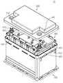
- FIG. 1is a view for explaining a battery pack according to an embodiment of the present invention.
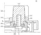
- FIG. 2 and 3are partial cross-sectional views of main parts of the battery pack of FIG. 1.
- FIG. 4is a diagram for describing a vehicle including the battery pack of FIG. 1.
- FIG. 1is a view for explaining a battery pack according to an embodiment of the present invention
- Figures 2 and 3is a partial cross-sectional view of the main part of the battery pack of FIG.
- the battery pack 10includes a pack case 100, a cell assembly 200, a pack cover 300, and a lead connecting substrate 400.
- the pack case 100may form an appearance of the battery pack 10.
- the pack case 100may be provided with an accommodation space for accommodating the cell assembly 200.
- the cell assembly 200is accommodated in the pack case 100 and may be provided as a module assembly consisting of a plurality of battery cells.
- Each battery cellincludes an electrode assembly having a positive electrode plate and a negative electrode plate disposed with a separator interposed therebetween, a battery case sealingly accommodating the electrode assembly together with an electrolyte solution, and an electrode lead protruding out of the battery case and comprising an anode terminal and a cathode terminal. It may include.
- the plurality of battery cellsmay be mounted on a cartridge, respectively, and connected to each other to form the cell assembly 200.
- the pack cover 300may cover one side of the pack case 100 to package the cell assembly 200.
- the pack cover 300may be welded to the pack case 100 along an edge.
- the welding methodmay be laser welding.
- the welding methodis not limited to laser welding, but other welding methods may be possible.
- packaging can be enabledit may be possible to mount the pack cover 300 to the pack case 100 in a manner other than welding.
- the pack cover 300may include a terminal through part 310.
- the terminal through part 310may pass through the terminal 410 to be described later to expose the outside of the pack cover 300, and may be provided to correspond to the number of the terminals 410.
- the terminal 410is provided in a pair, and the terminal through part 310 may also be provided in a pair corresponding thereto.
- the pair of terminal through parts 310may be provided at one side and the other side of the pack cover 300, respectively.
- the terminal through part 310may include a first inner wall 312 and a second inner wall 316.
- the first inner wall 312may be in contact with an outer surface of the terminal 410 penetrated in a hollow shape.
- the first inner wall 312is formed to have an inner diameter of a size corresponding to the outer diameter of the terminal 410 may be in full contact with the outer surface of the terminal 410.
- the terminal through part 310primarily penetrates moisture or foreign matter from the outside of the pack cover 300 through the first inner wall 312 in close contact with the outer surface of the terminal 410. It can be blocked first.
- the second inner wall 316extends stepped from the first inner wall 312 to have an inner diameter larger than that of the first inner wall 312, and may be in contact with the terminal insert portion 420 to be described later. have.
- the lead connecting substrate 400connects electrode leads of each battery cell of the cell assembly 200 to each other, and is provided between the cell assembly 200 and the pack cover 300 to provide the pack cover 300. It may be packaged in the pack case 100 together with the cell assembly 200 by.
- the terminal 410may be inserted into the lead connection board 400 to be penetrated out of the pack cover 300 to be connected to an external power source.
- the lead connection substrate 400may include a terminal insert portion 420 and a bus bar 430.
- the terminal 410may be provided as a pair, and may be inserted into the lead connecting substrate 400 and penetrated through the terminal through part 310 of the pack cover 300 to be out of the pack cover 300. It may be exposed and electrically connected to an external power source.
- the terminal insert part 420is injected into the terminal insert part 420, and may be provided to correspond to the number of the terminal 410.
- the terminal 410is provided in a pair, the terminal insert portion 420 may also be provided in a pair.
- the pair of terminal inserts 420, the respective terminal 410is injected through the terminal penetrating through the terminal through 310, corresponding to the pair of terminal through 310 It may be provided on one side and the other side of the lead connecting substrate 400 which is a position.
- the terminal 410since the terminal 410 is insert-extruded through the terminal insert part 420, the terminal 410 may be more firmly mounted on the lead connecting substrate 400.
- the gap between the terminal 410 and the terminal insert portion 410can be achieved through the insert injection, and is provided at the bottom of the lead connection substrate 400 without a separate sealing member for waterproofing. Infiltration of moisture or foreign matter into the cell assembly 200 may be effectively prevented.
- the terminal insert portion 420may be mounted to be engaged with the second inner wall 316 of the terminal through portion 310 at the side facing the terminal through portion 310.
- the outer diameter of the side of the terminal insert portion 420 facing the terminal through part 310may be formed to have a size corresponding to the inner diameter of the second inner wall 316.
- the outer circumferential width of the terminal insert portion 420may be wider than the outer circumferential width of the terminal 410.
- the terminal insert part 420is interlocked with the second inner wall 316 even if moisture or foreign matter is penetrated through the first inner wall 312 of the terminal through part 310. Secondly, additional penetration of water or foreign matter can be prevented.
- the terminal insert portion 420may be connected to the terminal through portion 310 of the pack cover 300 by welding.
- the welding of the terminal insert portion 420 and the terminal through portion 310may be laser welding. Through the laser welding, the terminal insert portion 420 may be more firmly mounted to the terminal through portion 310 and may also increase a sealing effect for preventing penetration of moisture or foreign matter.
- the bus bar 430electrically connects the electrode leads of the battery cell, and also electrically connects the electrode leads of the battery cell and the terminal 410. To this end, the bus bar 430 may be provided in plurality in the lead connection substrate 400.
- the bus bar 430 electrically connecting the electrode leads of the battery cell and the terminal 410may be a pair of the terminals 410 in this embodiment. It may be provided in pairs.
- the bus bar denoted by reference numeral 430 in the present embodimentis limited to the bus bar connecting the electrode leads and the terminal 410.
- the bus bar 430may be connected to the terminal 410 in the terminal insert part 420.
- the connection between the bus bar 430 and the terminal 410may be made through a screw member S of a conductive material.
- the battery pack 10 according to the present embodimentcan effectively implement a waterproof function that can prevent moisture infiltration, etc. without an additional separate sealing member.
- the battery pack 10 according to the present embodimentdoes not require a separate sealing member for waterproofing, and thus can prevent additional costs, thereby improving manufacturing efficiency.
- FIG. 4is a diagram for describing a vehicle including the battery pack of FIG. 1.
- the vehicle Vmay include the battery pack 10 according to the above-described embodiment.
- the vehicle V including the battery pack 10may be an electric vehicle or a hybrid vehicle.
- the battery pack 10can be used as a power source, it can of course be applied to other types of automobiles.
Landscapes
- Chemical & Material Sciences (AREA)
- Chemical Kinetics & Catalysis (AREA)
- Electrochemistry (AREA)
- General Chemical & Material Sciences (AREA)
- Engineering & Computer Science (AREA)
- Aviation & Aerospace Engineering (AREA)
- Microelectronics & Electronic Packaging (AREA)
- Manufacturing & Machinery (AREA)
- Life Sciences & Earth Sciences (AREA)
- Sustainable Development (AREA)
- Sustainable Energy (AREA)
- Power Engineering (AREA)
- Transportation (AREA)
- Mechanical Engineering (AREA)
- Battery Mounting, Suspending (AREA)
- Connection Of Batteries Or Terminals (AREA)
Abstract
Description
Translated fromKorean본 발명은 배터리 팩 및 이를 포함하는 자동차에 관한 것이다.The present invention relates to a battery pack and a vehicle including the same.
본 출원은 2015년 07월 20일 자로 출원된 한국 특허출원번호 제10-2015-0102610호에 대한 우선권주장출원으로서, 해당 출원의 명세서 및 도면에 개시된 모든 내용은 인용에 의해 본 출원에 원용된다.This application is a priority application for Korean Patent Application No. 10-2015-0102610 filed on July 20, 2015, and all contents disclosed in the specification and drawings of the application are incorporated herein by reference.
현재 상용화된 이차 전지로는 니켈 카드뮴 전지, 니켈 수소 전지, 니켈 아연 전지, 리튬 이차 전지 등이 있는데, 이 중에서 리튬 이차 전지는 니켈 계열의 이차 전지에 비해 메모리 효과가 거의 일어나지 않아 충 방전이 자유롭고, 자가 방전율이 매우 낮으며 에너지 밀도가 높은 장점으로 각광을 받고 있다.Commercially available secondary batteries include nickel cadmium batteries, nickel hydride batteries, nickel zinc batteries, and lithium secondary batteries. Among them, lithium secondary batteries have almost no memory effect compared to nickel-based secondary batteries, and thus are free of charge and discharge. The self-discharge rate is very low and the energy density is high.
이러한 리튬 이차 전지는 주로 리튬계 산화물과 탄소재를 각각 양극 활물질과 음극 활물질로 사용한다. 리튬 이차 전지는, 이러한 양극 활물질과 음극 활물질이 각각 도포된 양극판과 음극판이 세퍼레이터를 사이에 두고 배치된 전극 조립체와, 전극 조립체를 전해액과 함께 밀봉 수납하는 외장재, 즉 전지 케이스를 구비한다.Such lithium secondary batteries mainly use lithium-based oxides and carbon materials as positive electrode active materials and negative electrode active materials, respectively. The lithium secondary battery includes an electrode assembly in which a positive electrode plate and a negative electrode plate coated with the positive electrode active material and the negative electrode active material are disposed with a separator interposed therebetween, and a packaging material that seals the electrode assembly together with the electrolyte solution, that is, a battery case.
최근에는 휴대형 전자기기와 같은 소형 장치뿐 아니라, 자동차나 전력저장장치와 같은 중대형 장치에도 이차 전지가 널리 이용되고 있다. 이러한 중대형 장치에 이용되는 경우, 이차 전지는 용량 및 출력을 높이기 위해 전기적으로 연결된 많은 수의 배터리 셀들을 패키징한 배터리 팩으로 구비된다.Recently, secondary batteries are widely used not only in small devices such as portable electronic devices but also in medium and large devices such as automobiles and power storage devices. When used in such a medium-to-large device, the secondary battery is provided as a battery pack in which a large number of battery cells are electrically connected to increase capacity and output.
이러한 배터리 팩에는 외부 전원과의 연결을 위해 터미널이 케이스 밖으로 관통되어 노출된다. 종래 배터리 팩에는 터미널을 관통시킬 수 있게 케이스에 마련되는 터미널 관통부를 통한 외부 수분이나 이물질 등의 케이스 내부 유입을 방지하기 위해 터미널과 터미널 관통부 사이에 고무 패킹부재와 같은 추가적인 별도의 실링부재가 장착된다.In such a battery pack, terminals are exposed through the case to connect to an external power source. In the conventional battery pack, an additional separate sealing member such as a rubber packing member is installed between the terminal and the terminal penetrating part to prevent inflow of external moisture or foreign matter through the terminal penetrating part provided in the case so as to penetrate the terminal. do.
그러나, 종래 배터리 팩에서는 실링부재가 부식되거나 또는 정확히 장착되지 않는 경우, 간극이 쉽게 발생되어 그 사이로 수분이나 이물질 등이 쉽게 케이스 내부로 침투하는 문제가 있다.However, in the conventional battery pack, when the sealing member is corroded or not correctly mounted, a gap is easily generated, and moisture or foreign matter, etc. easily penetrate into the case therebetween.
또한, 종래 배터리 팩에서는 방수를 위한 별도의 실링부재를 추가적으로 구비하여야 하므로, 이에 따른 제조 비용 상승을 초래하는 문제가 있다.In addition, the conventional battery pack has to be additionally provided with a separate sealing member for waterproofing, there is a problem causing a rise in the manufacturing cost accordingly.
그러므로, 이와 같은 추가적인 별도의 실링부재 없이 방수를 구현할 수 있는 배터리 팩을 제공할 수 있는 방안의 모색이 요청된다.Therefore, there is a demand for a method of providing a battery pack capable of implementing waterproofing without such an additional separate sealing member.
따라서, 본 발명의 목적은, 추가적인 별도의 실링부재 없이 방수를 구현할 수 있는 배터리 팩 및 이를 포함하는 자동차를 제공하는 데 있다.Accordingly, an object of the present invention is to provide a battery pack and a vehicle including the same, which can implement waterproofing without an additional separate sealing member.
상기 목적을 해결하기 위해, 본 발명은, 외관을 형성하는 팩 케이스; 상기 팩 케이스 내에 수용되며, 전극 리드를 구비하는 복수 개의 배터리 셀들로 이루어진 셀 조립체; 상기 셀 조립체를 패키징할 수 있게 상기 팩 케이스를 커버하는 팩 커버; 및 상기 셀 조립체와 상기 팩 커버 사이에 구비되고, 각각의 배터리 셀의 전극 리드들을 서로 연결하며, 상기 팩 커버 밖으로 관통되어 외부 전원과 연결되는 터미널이 인서트 사출되는 리드 연결 기판;을 포함하는 것을 특징으로 하는 배터리 팩을 제공한다.In order to solve the above object, the present invention, the pack case forming the appearance; A cell assembly accommodated in the pack case and comprising a plurality of battery cells having electrode leads; A pack cover covering the pack case to package the cell assembly; And a lead connecting substrate provided between the cell assembly and the pack cover, connecting electrode leads of each battery cell to each other, and having a terminal inserted through the pack cover and connected to an external power source for insert injection. A battery pack is provided.
상기 팩 커버는, 상기 터미널이 관통되는 터미널 관통부;를 포함하며, 상기 리드 연결 기판은, 상기 터미널이 인서트 사출되며, 상기 터미널 관통부와 용접되는 터미널 인서트부;를 포함할 수 있다.The pack cover may include a terminal through part through which the terminal penetrates, and the lead connecting substrate may include a terminal insert part through which the terminal is injected and welded to the terminal through part.
상기 터미널 관통부는, 상기 터미널의 외측면과 접촉되는 중공 형상의 제1 내벽; 및 상기 제1 내벽으로부터 단차지게 연장되며, 상기 터미널 인서트부와 접촉되는 제2 내벽;을 포함할 수 있다.The terminal through part may include a first inner wall having a hollow shape in contact with an outer surface of the terminal; And a second inner wall extending stepwise from the first inner wall and in contact with the terminal insert portion.
상기 터미널 인서트부는 상기 제2 내벽과 맞물릴 수 있다.The terminal insert portion may be engaged with the second inner wall.
상기 터미널 인서트부의 외주 폭은 상기 터미널의 외주 폭보다 넓을 수 있다.The outer circumferential width of the terminal insert portion may be wider than the outer circumferential width of the terminal.
상기 터미널 관통부와 상기 터미널 인서트부의 용접은 레이저 용접일 수 있다.Welding of the terminal through part and the terminal insert part may be laser welding.
상기 터미널 관통부는 상기 팩 커버의 일측 및 타측에 각각 마련되며, 상기 터미널 인서트부는 상기 터미널 관통부에 대응되게 상기 리드 연결 기판의 일측 및 타측에 각각 마련될 수 있다.The terminal through part may be provided at one side and the other side of the pack cover, respectively, and the terminal insert part may be provided at one side and the other side of the lead connecting substrate to correspond to the terminal through part, respectively.
상기 리드 연결 기판은, 상기 전극 리드들과 상기 터미널을 전기적으로 연결하기 위한 버스 바;를 더 포함하며, 상기 버스 바는, 상기 터미널 인서트부 내에서 상기 터미널과 연결될 수 있다.The lead connection substrate may further include a bus bar for electrically connecting the electrode leads and the terminal, wherein the bus bar may be connected to the terminal in the terminal insert portion.
상기 팩 커버는 테두리를 따라 상기 팩 케이스에 레이저 용접될 수 있다.The pack cover may be laser welded to the pack case along an edge.
아울러, 본 발명은, 전술한 실시예들에 따른 배터리 팩;을 포함하는 것을 특징으로 하는 자동차를 제공한다.In addition, the present invention provides a vehicle comprising a; battery pack according to the embodiments described above.
이상과 같은 다양한 실시예들에 따라, 추가적인 별도의 실링부재 없이 방수를 구현할 수 있는 배터리 팩 및 이를 포함하는 자동차를 제공할 수 있다.According to various embodiments as described above, it is possible to provide a battery pack and a vehicle including the same that can implement waterproof without an additional separate sealing member.
따라서, 본 실시예들에 따라, 방수를 위한 별도의 실링부재를 요구하지 않는 바, 이에 따른 추가적인 비용 발생을 막을 수 있어, 제조 효율을 보다 더 향상시킬 수 있다.Therefore, according to the present embodiments, it does not require a separate sealing member for waterproofing, it is possible to prevent the additional cost accordingly, it is possible to further improve the manufacturing efficiency.
도 1은 본 발명의 일 실시예에 따른 배터리 팩을 설명하기 위한 도면이다.1 is a view for explaining a battery pack according to an embodiment of the present invention.
도 2 및 도 3은 도 1의 배터리 팩의 주요부의 부분 단면도이다.2 and 3 are partial cross-sectional views of main parts of the battery pack of FIG. 1.
도 4는 도 1의 배터리 팩을 포함하는 자동차를 설명하기 위한 도면이다.4 is a diagram for describing a vehicle including the battery pack of FIG. 1.
본 발명은 첨부된 도면을 참조하여 본 발명의 바람직한 실시예를 상세히 설명함으로써 더욱 명백해 질 것이다. 여기서 설명되는 실시예는 발명의 이해를 돕기 위하여 예시적으로 나타낸 것이며, 본 발명은 여기서 설명되는 실시예와 다르게 다양하게 변형되어 실시될 수 있음이 이해되어야 할 것이다. 또한, 발명의 이해를 돕기 위하여, 첨부된 도면은 실제 축척대로 도시된 것이 아니라 일부 구성요소의 치수가 과장되게 도시될 수 있다.The invention will become more apparent by describing the preferred embodiments of the invention in detail with reference to the accompanying drawings. Embodiments described herein are shown by way of example in order to facilitate understanding of the invention, it should be understood that the present invention may be modified in various ways different from the embodiments described herein. In addition, in order to facilitate understanding of the invention, the accompanying drawings may not be drawn to scale, but the dimensions of some components may be exaggerated.
도 1은 본 발명의 일 실시예에 따른 배터리 팩을 설명하기 위한 도면이며, 도 2 및 도 3은 도 1의 배터리 팩의 주요부의 부분 단면도이다.1 is a view for explaining a battery pack according to an embodiment of the present invention, Figures 2 and 3 is a partial cross-sectional view of the main part of the battery pack of FIG.
도 1 내지 도 3을 참조하면, 배터리 팩(10)은 팩 케이스(100), 셀 조립체(200), 팩 커버(300) 및 리드 연결 기판(400)을 포함한다.1 to 3, the
상기 팩 케이스(100)는 상기 배터리 팩(10)의 외관을 형성할 수 있다. 이러한 상기 팩 케이스(100)에는 상기 셀 조립체(200)를 수용할 수 있는 수용 공간이 마련될 수 있다.The
상기 셀 조립체(200)는 상기 팩 케이스(100)에 수용되며, 복수 개의 배터리 셀들로 이루어진 모듈 조립체로 구비될 수 있다. 각각의 배터리 셀은 세퍼레이터를 사이에 두고 배치되는 양극판과 음극판을 구비하는 전극 조립체, 상기 전극 조립체를 전해액과 함께 밀봉 수납하는 전지 케이스 및 상기 전지 케이스 밖으로 돌출되고 양극 단자와 음극 단자로 이루어진 전극 리드를 포함할 수 있다. 이러한 상기 복수 개의 배터리 셀들은 각각 카트리지 등에 장착되어 서로 연결되어 상기 셀 조립체(200)를 이룰 수 있다.The
상기 팩 커버(300)는 상기 셀 조립체(200)를 패키징할 수 있게 상기 팩 케이스(100)의 일측을 커버할 수 있다. 이러한 패키징을 위해 상기 팩 커버(300)는 테두리를 따라 상기 팩 케이스(100)에 용접될 수 있다. 여기서, 용접 방식은 레이저 용접일 수 있다. 상기 용접 방식의 경우, 레이저 용접에 한정되는 것은 아니며 기타 다른 용접 방식도 가능할 수 있다. 또한, 패키징을 가능하게 할 수 있다면 용접이 아닌 기타 다른 방식으로 상기 팩 커버(300)를 상기 팩 케이스(100)에 장착하는 것도 가능할 수 있다.The
상기 팩 커버(300)는 터미널 관통부(310)를 포함할 수 있다.The
상기 터미널 관통부(310)는 후술하는 터미널(410)을 관통시켜 상기 팩 커버(300) 밖으로 노출시키며, 상기 터미널(410)의 개수에 대응되게 구비될 수 있다. 상기 터미널(410)은 한 쌍으로 구비되는 바, 상기 터미널 관통부(310) 또한 이에 대응되게 한 쌍으로 구비될 수 있다. 한 쌍의 터미널 관통부(310)는 각각, 상기 팩 커버(300)의 일측 및 타측에 각각 마련될 수 있다.The terminal through
상기 터미널 관통부(310)는 제1 내벽(312) 및 제2 내벽(316)을 포함할 수 있다.The terminal through
상기 제1 내벽(312)은 중공 형상으로 관통되는 상기 터미널(410)의 외측면과 접촉될 수 있다. 여기서, 상기 제1 내벽(312)은 상기 터미널(410)의 외경에 대응되는 크기의 내경을 갖도록 형성되어 상기 터미널(410)의 외측면에 완전히 밀착 접촉될 수 있다.The first
이에 따라, 상기 터미널 관통부(310)는 상기 터미널(410)의 외측면에 밀착 접촉되는 상기 제1 내벽(312)을 통해 상기 팩 커버(300) 외측으로부터 수분이나 이물질 등의 침투를 먼저 일차적으로 우선적으로 차단할 수 있다.Accordingly, the terminal through
상기 제2 내벽(316)은 상기 제1 내벽(312)의 내경보다 큰 내경을 가질 수 있게 상기 제1 내벽(312)으로부터 단차지게 연장되며, 후술하는 상기 터미널 인서트부(420)와 접촉될 수 있다.The second
상기 리드 연결 기판(400)은 상기 셀 조립체(200)의 각각의 배터리 셀의 전극 리드들을 서로 연결하며, 상기 셀 조립체(200)와 상기 팩 커버(300) 사이에 구비되어 상기 팩 커버(300)에 의해 상기 셀 조립체(200)와 함께 상기 팩 케이스(100) 내에 패키징될 수 있다.The
이러한 상기 리드 연결 기판(400)에는 상기 팩 커버(300) 밖으로 관통되어 외부 전원과 연결되기 위한 상기 터미널(410)이 인서트 사출될 수 있다. 아울러, 상기 리드 연결 기판(400)은 터미널 인서트부(420) 및 버스 바(430)를 포함할 수 있다.The
상기 터미널(410)은 한 쌍으로 구비될 수 있으며, 상기 리드 연결 기판(400)에 인서트 사출되어 상기 팩 커버(300)의 상기 터미널 관통부(310)를 통해 관통되어 상기 팩 커버(300) 밖으로 노출되어 외부 전원 등과 전기적으로 연결될 수 있다.The
상기 터미널 인서트부(420)에는 상기 터미널(410)이 인서트 사출되며, 상기 터미널(410)의 개수에 대응되게 구비될 수 있다. 상기 터미널(410)은 한 쌍으로 구비되는 바, 상기 터미널 인서트부(420) 또한 한 쌍으로 구비될 수 있다.The
아울러, 상기 한 쌍의 터미널 인서트부(420)는, 인서트 사출된 상기 각각의 터미널(410)이 상기 터미널 관통부(310)에 관통되어야 하는 바, 상기 한 쌍의 터미널 관통부(310)에 대응되는 위치인 상기 리드 연결 기판(400)의 일측 및 타측에 각각 마련될 수 있다.In addition, the pair of
본 실시예에서는 상기 터미널 인서트부(420)를 통해 상기 터미널(410)을 인서트 사출시키므로, 상기 터미널(410)을 보다 견고히 상기 리드 연결 기판(400)에 안정적으로 장착시킬 수 있다.In the present exemplary embodiment, since the terminal 410 is insert-extruded through the
아울러, 이러한 인서트 사출을 통해 상기 터미널(410)과 상기 터미널 인서트부(410) 사이의 간극 없는 밀봉을 도모할 수 있는 바, 방수를 위한 별도의 실링부재 없이도 상기 리드 연결 기판(400) 저부에 구비되는 상기 셀 조립체(200)로의 수분이나 이물질 등의 침투를 효과적으로 방지할 수 있다.In addition, the gap between the terminal 410 and the
그리고, 상기 터미널 인서트부(420)는 상기 터미널 관통부(310)를 마주하는 측에서 상기 터미널 관통부(310)의 상기 제2 내벽(316)과 맞물리도록 장착될 수 있다. 이를 위해, 상기 터미널 인서트부(420)의 상기 터미널 관통부(310)를 마주하는 측의 외경은 상기 제2 내벽(316)의 내경에 대응되는 크기로 형성될 수 있다. 다시 말해, 상기 터미널 인서트부(420)의 외주 폭은 상기 터미널(410)의 외주 폭보다 넓게 형성될 수 있다.The
이에 따라, 상기 터미널 인서트부(420)는, 만약, 상기 터미널 관통부(310)의 제1 내벽(312)을 통해 수분이나 이물질 등이 침투되더라도, 상기 제2 내벽(316)과 맞물리게 장착된 부분에서 이차적으로 수분이나 이물질 등의 침투를 추가적으로 방지할 수 있다.Accordingly, the
또한, 상기 터미널 인서트부(420)는 상기 팩 커버(300)의 상기 터미널 관통부(310)와 용접을 통해 연결될 수 있다. 여기서, 상기 터미널 인서트부(420)와 상기 터미널 관통부(310)의 용접은 레이저 용접일 수 있다. 이러한 레이저 용접을 통해 상기 터미널 인서트부(420)는 상기 터미널 관통부(310)에 보다 견고하게 장착될 수 있음과 아울러 수분이나 이물질 등의 침투 방지를 위한 실링 효과 또한 상승시킬 수 있다.In addition, the
상기 버스 바(430)는 상기 배터리 셀의 전극 리드들을 전기적으로 연결하고, 또한, 상기 배터리 셀의 전극 리드들과 상기 터미널(410)을 전기적으로 연결한다. 이를 위해, 상기 버스 바(430)는 상기 리드 연결 기판(400)에 복수 개로 구비될 수 있다.The
이러한 상기 복수 개의 버스 바들 중, 상기 배터리 셀의 전극 리드들과 상기 터미널(410)을 전기적으로 연결하는 버스 바(430)는, 본 실시예에서 상기 터미널(410)이 한 쌍인 바, 이에 대응되게 한 쌍으로 구비될 수 있다. 이하, 본 실시예에서 도면부호 430으로 표시되는 버스 바는 상기 전극 리드들과 상기 터미널(410)을 연결하는 버스 바인 것으로 한정하여 설명한다.Among the plurality of bus bars, the
상기 버스 바(430)는 상기 터미널 인서트부(420) 내에서 상기 터미널(410)과 연결될 수 있다. 여기서, 상기 버스 바(430)와 상기 터미널(410)의 연결은 도전성 재질의 스크류 부재(S)를 통해 이루어질 수 있다.The
이상과 같은 구조를 통해, 본 실시예에 따른 상기 배터리 팩(10)은 추가적인 별도의 실링부재 없이도 수분 침투 등을 방지할 수 있는 방수 기능을 효과적으로 구현할 수 있다.Through the structure as described above, the
따라서, 본 실시예에 따른 상기 배터리 팩(10)은 방수를 위한 별도의 실링부재를 요구하지 않는 바, 이에 따른 추가적인 비용 발생을 막을 수 있어, 제조 효율을 향상시킬 수 있다.Therefore, the
도 4는 도 1의 배터리 팩을 포함하는 자동차를 설명하기 위한 도면이다.4 is a diagram for describing a vehicle including the battery pack of FIG. 1.
도 4를 참조하면, 자동차(V)는 전술한 실시예에 따른 상기 배터리 팩(10)을 포함할 수 있다. 여기서, 이러한 상기 배터리 팩(10)을 포함하는 상기 자동차(V)는 전기 자동차 또는 하이브리드 자동차일 수 있다. 아울러, 상기 배터리 팩(10)을 동력원으로 이용할 수 있다면 기타 다른 방식의 자동차에도 적용될 수 있음은 물론이다.Referring to FIG. 4, the vehicle V may include the
이상에서는 본 발명의 바람직한 실시예에 대하여 도시하고 설명하였지만, 본 발명은 상술한 특정의 실시예에 한정되지 아니하며, 청구범위에서 청구하는 본 발명의 요지를 벗어남이 없이 당해 발명이 속하는 기술분야에서 통상의 지식을 가진자에 의해 다양한 변형실시가 가능한 것은 물론이고, 이러한 변형실시들은 본 발명의 기술적 사상이나 전망으로부터 개별적으로 이해돼서는 안 될 것이다.While the above has been shown and described with respect to preferred embodiments of the present invention, the present invention is not limited to the specific embodiments described above, it is usually in the technical field to which the invention belongs without departing from the spirit of the invention claimed in the claims. Various modifications can be made by those skilled in the art, and these modifications should not be individually understood from the technical spirit or the prospect of the present invention.
Claims (10)
Translated fromKoreanPriority Applications (5)
| Application Number | Priority Date | Filing Date | Title |
|---|---|---|---|
| PL16827977TPL3261151T3 (en) | 2015-07-20 | 2016-07-11 | Battery pack and vehicle comprising same |
| JP2017563559AJP6580715B2 (en) | 2015-07-20 | 2016-07-11 | Battery pack and automobile including the same |
| CN201680015779.1ACN107431159B (en) | 2015-07-20 | 2016-07-11 | Battery pack and vehicle including the same |
| US15/554,080US10752121B2 (en) | 2015-07-20 | 2016-07-11 | Battery pack and vehicle comprising the same |
| EP16827977.6AEP3261151B1 (en) | 2015-07-20 | 2016-07-11 | Battery pack and vehicle comprising same |
Applications Claiming Priority (2)
| Application Number | Priority Date | Filing Date | Title |
|---|---|---|---|
| KR1020150102610AKR101944957B1 (en) | 2015-07-20 | 2015-07-20 | Battery pack and vehicle comprising the same |
| KR10-2015-0102610 | 2015-07-20 |
Publications (1)
| Publication Number | Publication Date |
|---|---|
| WO2017014473A1true WO2017014473A1 (en) | 2017-01-26 |
Family
ID=57834203
Family Applications (1)
| Application Number | Title | Priority Date | Filing Date |
|---|---|---|---|
| PCT/KR2016/007526CeasedWO2017014473A1 (en) | 2015-07-20 | 2016-07-11 | Battery pack and vehicle comprising same |
Country Status (7)
| Country | Link |
|---|---|
| US (1) | US10752121B2 (en) |
| EP (1) | EP3261151B1 (en) |
| JP (1) | JP6580715B2 (en) |
| KR (1) | KR101944957B1 (en) |
| CN (1) | CN107431159B (en) |
| PL (1) | PL3261151T3 (en) |
| WO (1) | WO2017014473A1 (en) |
Cited By (1)
| Publication number | Priority date | Publication date | Assignee | Title |
|---|---|---|---|---|
| CN108987633A (en)* | 2018-07-11 | 2018-12-11 | 安徽江淮汽车集团股份有限公司 | A kind of automobile batteries modular structure |
Families Citing this family (11)
| Publication number | Priority date | Publication date | Assignee | Title |
|---|---|---|---|---|
| EP3463858B1 (en) | 2016-06-01 | 2021-10-20 | Wavin B.V. | A multi-layered pipe and a method for forming a multi-layered pipe |
| KR102175940B1 (en) | 2017-08-22 | 2020-11-06 | 주식회사 엘지화학 | Battery pack and vehicle comprising the same |
| KR102307299B1 (en)* | 2017-08-29 | 2021-09-30 | 주식회사 엘지화학 | Waterproof battery pack and method for manufacturing the same |
| JP7094697B2 (en)* | 2017-12-25 | 2022-07-04 | 矢崎総業株式会社 | Battery pack |
| KR102353367B1 (en)* | 2018-09-28 | 2022-01-18 | 주식회사 엘지에너지솔루션 | Battery cell assembly, battery module comprising the baatery cell assembly, battery pack comprising the battery module and vehicle comprising the battery pack |
| KR102646710B1 (en)* | 2019-01-17 | 2024-03-11 | 주식회사 엘지에너지솔루션 | Battery pack and device including the same |
| US12224603B2 (en) | 2020-06-02 | 2025-02-11 | Inventus Power, Inc. | Mode-based disabling of communication bus of a battery management system |
| US12301031B1 (en) | 2020-06-02 | 2025-05-13 | Inventus Power, Inc. | Large-format battery management systems with gateway PCBA |
| US11133690B1 (en) | 2020-06-02 | 2021-09-28 | Inventus Power, Inc. | Large-format battery management system |
| US11621462B2 (en)* | 2021-02-12 | 2023-04-04 | GM Global Technology Operations LLC | Battery modules with finger-proof electrical terminals for bolted busbar connections |
| US12142794B2 (en)* | 2021-12-13 | 2024-11-12 | Inventus Power, Inc. | Battery pack power connector |
Citations (5)
| Publication number | Priority date | Publication date | Assignee | Title |
|---|---|---|---|---|
| JPH03134956A (en)* | 1989-10-19 | 1991-06-07 | Matsushita Electric Ind Co Ltd | Lithium secondary battery |
| KR20130006280A (en)* | 2011-07-07 | 2013-01-16 | 삼성에스디아이 주식회사 | Rechargeable battery |
| CN202917549U (en)* | 2010-11-09 | 2013-05-01 | 三菱重工业株式会社 | Battery module |
| JP5213030B2 (en)* | 2008-04-17 | 2013-06-19 | 日立マクセル株式会社 | Sealed battery manufacturing method and sealed battery |
| KR101347194B1 (en)* | 2012-05-19 | 2014-01-06 | 주식회사 델코 | Terminal having electolyte anti leakage structure |
Family Cites Families (12)
| Publication number | Priority date | Publication date | Assignee | Title |
|---|---|---|---|---|
| JP2004265830A (en) | 2003-03-04 | 2004-09-24 | Japan Storage Battery Co Ltd | Battery pack |
| JP2006344447A (en)* | 2005-06-08 | 2006-12-21 | Kokusan Denki Co Ltd | Vehicular battery/electric unit combined structure |
| DE102005046256B4 (en)* | 2005-09-27 | 2010-09-30 | Vb Autobatterie Gmbh & Co. Kgaa | Lead-acid battery and plastic battery cover for this purpose |
| CA2785380C (en)* | 2009-12-24 | 2020-03-10 | Gs Yuasa International Ltd. | Lid for storage battery, injection molding method of the same lid, storage battery with the same lid, and terminal section for storage battery |
| US9472797B2 (en) | 2011-05-25 | 2016-10-18 | Samsung Sdi Co., Ltd. | Battery pack |
| JP5987465B2 (en)* | 2011-06-17 | 2016-09-07 | 株式会社Gsユアサ | Storage element and method for manufacturing the same |
| CN202167550U (en)* | 2011-06-29 | 2012-03-14 | 比亚迪股份有限公司 | A battery cover assembly and battery |
| JP6087544B2 (en)* | 2012-09-04 | 2017-03-01 | 株式会社東芝 | Assembled battery |
| JP2015011849A (en)* | 2013-06-28 | 2015-01-19 | 三洋電機株式会社 | Battery provided with auxiliary battery |
| KR101737489B1 (en)* | 2014-06-05 | 2017-05-18 | 주식회사 엘지화학 | Battery pack having improved structure for supporting torque of terminal bolt |
| KR102201306B1 (en)* | 2014-06-17 | 2021-01-11 | 삼성에스디아이 주식회사 | Secondary Battery |
| US10056598B2 (en)* | 2014-08-26 | 2018-08-21 | Johnson Controls Technology Company | Recessed terminal in module body |
- 2015
- 2015-07-20KRKR1020150102610Apatent/KR101944957B1/enactiveActive
- 2016
- 2016-07-11JPJP2017563559Apatent/JP6580715B2/enactiveActive
- 2016-07-11EPEP16827977.6Apatent/EP3261151B1/enactiveActive
- 2016-07-11WOPCT/KR2016/007526patent/WO2017014473A1/ennot_activeCeased
- 2016-07-11USUS15/554,080patent/US10752121B2/enactiveActive
- 2016-07-11CNCN201680015779.1Apatent/CN107431159B/enactiveActive
- 2016-07-11PLPL16827977Tpatent/PL3261151T3/enunknown
Patent Citations (5)
| Publication number | Priority date | Publication date | Assignee | Title |
|---|---|---|---|---|
| JPH03134956A (en)* | 1989-10-19 | 1991-06-07 | Matsushita Electric Ind Co Ltd | Lithium secondary battery |
| JP5213030B2 (en)* | 2008-04-17 | 2013-06-19 | 日立マクセル株式会社 | Sealed battery manufacturing method and sealed battery |
| CN202917549U (en)* | 2010-11-09 | 2013-05-01 | 三菱重工业株式会社 | Battery module |
| KR20130006280A (en)* | 2011-07-07 | 2013-01-16 | 삼성에스디아이 주식회사 | Rechargeable battery |
| KR101347194B1 (en)* | 2012-05-19 | 2014-01-06 | 주식회사 델코 | Terminal having electolyte anti leakage structure |
Non-Patent Citations (1)
| Title |
|---|
| See also references ofEP3261151A4* |
Cited By (1)
| Publication number | Priority date | Publication date | Assignee | Title |
|---|---|---|---|---|
| CN108987633A (en)* | 2018-07-11 | 2018-12-11 | 安徽江淮汽车集团股份有限公司 | A kind of automobile batteries modular structure |
Also Published As
| Publication number | Publication date |
|---|---|
| JP6580715B2 (en) | 2019-09-25 |
| JP2018521468A (en) | 2018-08-02 |
| EP3261151A1 (en) | 2017-12-27 |
| CN107431159A (en) | 2017-12-01 |
| US10752121B2 (en) | 2020-08-25 |
| EP3261151A4 (en) | 2018-03-14 |
| US20180034012A1 (en) | 2018-02-01 |
| PL3261151T3 (en) | 2019-05-31 |
| KR101944957B1 (en) | 2019-02-01 |
| KR20170010666A (en) | 2017-02-01 |
| CN107431159B (en) | 2020-01-17 |
| EP3261151B1 (en) | 2019-01-09 |
Similar Documents
| Publication | Publication Date | Title |
|---|---|---|
| WO2017014473A1 (en) | Battery pack and vehicle comprising same | |
| WO2016105013A1 (en) | Bms integrated compact secondary battery module | |
| WO2018236018A1 (en) | Battery pack | |
| WO2019107795A1 (en) | Battery pack | |
| WO2013027935A1 (en) | Battery module | |
| WO2019146892A1 (en) | Battery module comprising a housing with integrated bus bar | |
| WO2017073908A1 (en) | Battery module and battery pack comprising same | |
| WO2018093038A1 (en) | Battery module, and battery pack comprising same | |
| WO2017217641A1 (en) | Battery module, and battery pack and vehicle comprising same | |
| WO2017061709A1 (en) | Battery module and battery pack comprising same | |
| WO2021221300A1 (en) | Battery module and battery pack comprising same | |
| WO2019031723A1 (en) | Battery module and battery module manufacturing method | |
| KR101711994B1 (en) | Rechargeable battery module | |
| WO2014123329A1 (en) | Battery cell including stepped structure | |
| WO2014054888A2 (en) | Battery pack | |
| WO2020138848A1 (en) | Battery module, battery pack comprising same battery module, and vehicle comprising same battery pack | |
| WO2019066229A1 (en) | Battery module and battery pack comprising same | |
| WO2020060039A1 (en) | Battery module, battery pack comprising battery module, and vehicle comprising battery pack | |
| WO2019050180A1 (en) | Secondary battery | |
| WO2019112197A1 (en) | Cylindrical secondary battery module | |
| KR102134120B1 (en) | Low profile sensor and electrochemical cell containing same | |
| WO2017061707A1 (en) | Battery module and battery pack comprising same | |
| WO2021038545A1 (en) | Pouch-type battery case and pouch-type secondary battery | |
| WO2021075690A1 (en) | Battery module | |
| WO2019212134A1 (en) | Battery module and battery pack containing same |
Legal Events
| Date | Code | Title | Description |
|---|---|---|---|
| 121 | Ep: the epo has been informed by wipo that ep was designated in this application | Ref document number:16827977 Country of ref document:EP Kind code of ref document:A1 | |
| REEP | Request for entry into the european phase | Ref document number:2016827977 Country of ref document:EP | |
| ENP | Entry into the national phase | Ref document number:2017563559 Country of ref document:JP Kind code of ref document:A | |
| NENP | Non-entry into the national phase | Ref country code:DE |