WO2017014344A1 - Automatic calibration device for non-destructive ultrasound inspection device, and control method therefor - Google Patents
Automatic calibration device for non-destructive ultrasound inspection device, and control method thereforDownload PDFInfo
- Publication number
- WO2017014344A1 WO2017014344A1PCT/KR2015/007782KR2015007782WWO2017014344A1WO 2017014344 A1WO2017014344 A1WO 2017014344A1KR 2015007782 WKR2015007782 WKR 2015007782WWO 2017014344 A1WO2017014344 A1WO 2017014344A1
- Authority
- WO
- WIPO (PCT)
- Prior art keywords
- specimen
- ultrasonic
- main controller
- calibration device
- input
- Prior art date
- Legal status (The legal status is an assumption and is not a legal conclusion. Google has not performed a legal analysis and makes no representation as to the accuracy of the status listed.)
- Ceased
Links
Images


Classifications
- G—PHYSICS
- G01—MEASURING; TESTING
- G01N—INVESTIGATING OR ANALYSING MATERIALS BY DETERMINING THEIR CHEMICAL OR PHYSICAL PROPERTIES
- G01N29/00—Investigating or analysing materials by the use of ultrasonic, sonic or infrasonic waves; Visualisation of the interior of objects by transmitting ultrasonic or sonic waves through the object
- G01N29/04—Analysing solids
- G—PHYSICS
- G01—MEASURING; TESTING
- G01N—INVESTIGATING OR ANALYSING MATERIALS BY DETERMINING THEIR CHEMICAL OR PHYSICAL PROPERTIES
- G01N29/00—Investigating or analysing materials by the use of ultrasonic, sonic or infrasonic waves; Visualisation of the interior of objects by transmitting ultrasonic or sonic waves through the object
- G01N29/22—Details, e.g. general constructional or apparatus details
- G01N29/26—Arrangements for orientation or scanning by relative movement of the head and the sensor
- G01N29/27—Arrangements for orientation or scanning by relative movement of the head and the sensor by moving the material relative to a stationary sensor
- G—PHYSICS
- G01—MEASURING; TESTING
- G01N—INVESTIGATING OR ANALYSING MATERIALS BY DETERMINING THEIR CHEMICAL OR PHYSICAL PROPERTIES
- G01N29/00—Investigating or analysing materials by the use of ultrasonic, sonic or infrasonic waves; Visualisation of the interior of objects by transmitting ultrasonic or sonic waves through the object
- G01N29/22—Details, e.g. general constructional or apparatus details
- G01N29/30—Arrangements for calibrating or comparing, e.g. with standard objects
Definitions
- the present inventionrelates to an automatic calibration device for a non-destructive ultrasonic inspection apparatus and a control method thereof. More particularly, a pipe specimen having a turn table and an XY table installed on a pipe under inspection and a defect portion such as a crack or a hole is formed on the XY table.
- An automatic calibration apparatus for a non-destructive ultrasonic inspection apparatuscapable of calibrating an ultrasonic inspection apparatus by displaying a signal for detecting a bad state of the oligomer and a control method thereof.
- Non-destructive ultrasonographysends sound waves above the audible range, usually ultrasound frequencies of 0.5 to 15 Mc, to the specimen to be inspected by defects caused by internal confusion or by the presence of uneven layers. How to detect.
- Ultrasonic waveshave a short wavelength and go straight. Ultrasonic speed is about 330m / s in air, about 1500m / s in water, and about 6000m / s in river. do.
- water or glycerinis coated on the surface of the steel to bring the ultrasonic oscillator into contact.
- the ultrasonic waveis detected by detecting the strongest reflection of the ultrasonic wave from the internal defect.
- the welding beadsmay have welding defects such as pin holes or blow holes caused by the mixed gas, and shrinkage holes caused by shrinkage during solidification.
- the pin holeis a pore having a diameter of 2-3mm or less and usually exists in a state in which a plurality of holes are gathered
- the blow holeis a pore generated in the weld metal. It is a hole of.
- the inspection method using ultrasonic wavesis advantageous because only one side of the weld can be accessed and is less affected by heat, light and electromagnetic fields generated during welding.
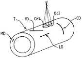
- FIG. 9is a schematic perspective view of a pipe having defects or defects of the pipe.
- the inner or outer surface defectsinclude longitudinal defects LD and circumferential (or transverse or intersecting or transverse) defects CD, and tilted or oblique direction defects ID, and the ultrasonic sensor
- the defectsmay be standard requirements, specification requirements, or customer requirements (e.g., the length value of the defects mentioned in the standard is 1 ⁇ 2 at a depth of approximately 5% of the thickness of the product being inspected). Attempts to detect them immediately beyond the range of lengths and depths specified in inches or approximately 12.7 mm).
- defects in the "pipe wall" of interestthat is, defects in the mass (not shown in Figure 1), are often formed in the inclusions and cracked distal ends, and their detection is due to the measurement of thickness and Tried together Ultrasonic beams are shown scanning at one point in FIG. 9 to illustrate detection of defects. In practice, the ultrasound beams converge at almost one point.
- the present inventionis to solve the above problems, an object of the present invention is to provide an automatic calibration device for a non-destructive ultrasonic inspection apparatus and a control method thereof that can simplify and speed up the calibration (calibration) process of the ultrasonic inspection apparatus. will be.
- Another object of the present inventionis to provide a non-destructive ultrasonic inspection device that can be easily and quickly calibrated by manufacturing the specimens that can be calibrated to be easily handled and installed so that the specimens can be rotated and moved in the XY axis direction on the pipe being produced. It is to provide a calibration device and a control method thereof.
- an automatic calibration device for a non-destructive ultrasonic inspection apparatusincludes an XY table fixed on two pipes being produced and moving in the X-axis or Y-axis direction; A turn table rotatably mounted on the XY table; A specimen fixing plate installed on the turn table to fix the specimen; A plurality of ultrasonic sensors for detecting defects formed in the specimen; A main controller controlling the XY table, the turn table, and the Y-axis table to move the specimen so that the ultrasonic sensor detects a defect of the specimen and displays the input and display means; It characterized in that it comprises an input and display means for displaying a defect of the specimen detected by the plurality of ultrasonic sensors.
- Y-axis tablefor adjusting the position of the specimen by moving in the transverse direction (Y-axis direction) across the pipe under the control of the main controller It characterized in that it further comprises.
- the XY tableincludes a plurality of fixed legs to which a plurality of hinges are attached to both ends and is attached to the outer surface of the pipe by attachment means that are defective by hinges attached to the lower ends of the fixed legs. By being attached, the XY table is configured to be fixed to the pipe.
- the XY tablehas a top plate body formed in a rectangular plate shape; Four fixed legs rotatably installed at four corners of the upper plate body by an upper hinge and having a “s” shape; It characterized in that it comprises a mounting means rotatably installed by the lower hinge to the lower end of the fixed leg.
- the upper plate body of the XY tableis horizontally maintained by the upper hinge, the four fixing legs and the lower hinge so that the specimen fixed to the specimen fixing plate is horizontal so that ultrasonic inspection is stable. And configured to be executable.
- the turn tableis installed on the upper plate body of the XY table, and rotates around a rotation axis; It characterized in that it comprises a rectangular support plate in the form of a square plate integrally attached to the upper surface of the rotating disk.
- the rotating disc of the turn tableis configured to be adjusted by the locking device after the rotation by rotating the specimen so that the ultrasonic wave emitted from the ultrasonic sensor is incident to the direction of the defect. It features.
- the specimen holding plateis formed in a flat horizontal plane so that the specimen is placed on a horizontal plane, and a plurality of “a” shaped fixing pieces are fixed to the specimen holding plate by the fixing bolts. It is characterized in that it is configured to.
- the plurality of ultrasonic sensorsare attached to an ultrasonic sensor support plate attached to an ultrasonic sensor support that moves under the control of the main controller, and injects ultrasonic waves into a specimen under the control of the main controller. And receiving ultrasonic waves reflected from the defect portions formed on the specimen and outputting the ultrasonic waves to the main controller to detect the defect portions formed on the specimen.
- the control method of the automatic calibration device for a non-destructive ultrasonic inspection apparatusincludes the steps of the main controller to check the specimen by moving the specimen detection sensor to a position corresponding to the position data input by the inspector through the input and display means; Aligning, by the main controller, the ultrasonic sensor and the specimen defective portion by the position data of the specimen and the position data of the defect portion input by the inspector; Checking, by the main controller, a scan zero point at which the ultrasonic sensor starts scanning, scanning and scanning an ultrasonic signal while advancing the ultrasonic sensor toward a defective portion input by the inspector; The main controller performing a zigzag scan around the defective portion near the defective portion input by the inspector; And storing, by the main controller, a reflection position where the ultrasonic signal is reflected during the scanning of the defective portion in the internal memory and displaying the level of the reflection signal on the display means.
- the automatic calibration device for a non-destructive ultrasonic inspection apparatusAccording to the automatic calibration device for a non-destructive ultrasonic inspection apparatus according to the present invention, it is possible to quickly and accurately install the calibration device of the ultrasonic scanner has the effect of improving the reliability and efficiency of the calibration.
- the size of the specimenis small, easy to carry and simple to manufacture, it is easy to install and save time accordingly, productivity is improved, and the ultrasonic sensor installed at any angle by XY table and turn table can be calibrated. There is an advantage to this.
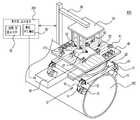
- FIG. 1is a perspective view showing the configuration of an automatic calibration device for a non-destructive ultrasonic inspection apparatus according to the present invention
- Figure 2is a front view showing the configuration of the automatic calibration device for non-destructive ultrasonic inspection apparatus according to the present invention
- 5 to 7is a process of scanning and calibrating the defect portion formed on the specimen by the automatic calibration device according to the present invention
- FIG. 8is a flowchart showing a control method of an automatic calibration device for a non-destructive ultrasonic inspection apparatus according to the present invention.
- FIG. 9is a schematic perspective view of a pipe having defects or defects of the pipe.
- FIG. 1 and 2are a perspective view and a front view showing the configuration of an automatic calibration device for a non-destructive ultrasonic inspection apparatus according to the present invention.
- the auto-calibration apparatus 100 for a non-destructive ultrasonic inspection apparatusis fixed on the production pipe 200, the XY table 10 to move in the X-axis or Y-axis direction under the control of the main controller 60 and; A turn table (20) rotatably mounted on the XY table (10); A Y-axis table 30 mounted on the turn table 20 to move in the Y-axis direction under the control of the main controller 60; A specimen fixing plate 40 installed on the Y-axis table 30 to fix the specimen 210; A plurality of ultrasonic sensors 50 for detecting defects such as cracks and holes formed in the specimen 210; The main controller controls the XY table 10 to move the specimen 210 so that the ultrasonic sensor 50 detects cracks, holes, etc. of the specimen 210 and displays them on the input and display means 70.
- a controller 60It comprises an input and display means 70 for displaying a defect of the specimen 210 detected by the plurality of ultrasonic sensors 50.
- XY table 10according to the present invention and the top plate body 11 is formed in a rectangular plate shape;
- Four fixed legs (13)rotatably installed at four corners of the upper plate body (11) by an upper hinge (12) and having a “s” shape;
- Itcomprises a mounting means 15, such as a magnet rotatably installed by the lower hinge 14 in the lower end of the fixed leg (13).
- the XY table 10is attached by rotating the upper hinge 12 and the lower hinge 14 to attach the four fixed legs 11 to the outer surface of the pipe 200 by four attachment means 14.
- the XY table 10is fixed to the pipe 200 by being bonded by the magnetic force of the means 14.
- the upper plate body 11 of the XY table 10is formed in the form of a flat square plate and placed on the upper surface of the pipe 200, as shown in FIG. 2, the outer peripheral circle of the pipe 200, the upper plate body ( 11) is fixed to the upper surface of the pipe 200 in a horizontal state by the upper hinge 12 and four fixing legs 13 and the lower hinge 14 installed on the four corners.
- the upper plate body 11Since the four fixed legs 13 are rotatably installed by the upper hinge 12 and the lower hinge 14 so as to circumscribe the outer circumferential circle of the pipe 200 and have a "S" shape, the upper plate body 11 is In the state circumferentially circumscribed to the outer circumferential circle of the round pipe 200, the angles of the four fixed legs 13 are adjusted twice by the upper hinge 12 and the lower hinge 14, so that the outer circumferential circle of the pipe 200.
- the upper plate body 11may be fixed to the pipe 200 in a state in which the upper plate body 11 is attached in contact with the upper plate body 11.
- the upper plate body 11 of the XY table 10is horizontally maintained by the upper hinge 12, the four fixing legs 13, and the lower hinge 14, so that the specimen 210 is fixed to the specimen fixing plate 40. By keeping this level, the ultrasonic examination can be performed stably.
- the turn table 20is provided on the upper plate body 11 of the XY table 10, the rotation disk 21 for rotating around a rotation axis (not shown); It comprises a square support plate 22 of the square plate form integrally attached to the upper surface of the rotating disc 21.
- the rotating disc 21 of the turn table 20is rotated and then locked by a locking device (not shown), for example, by a locking device configured to hold a fixing pin on the teeth formed on the rotating disc 21.
- a locking deviceconfigured to hold a fixing pin on the teeth formed on the rotating disc 21.
- the diameter of the rotating disc 21may be formed smaller than the upper plate body 11 of the XY table 10, the square support plate 22 installed on the rotating disc 21 is a transverse direction (crossing the pipe 200) And a rectangular plate formed longer in the Y-axis direction).
- the Y-axis table 30is formed on the turn table 20, and moves in the horizontal direction (Y-axis direction) across the pipe 200 under the control of the main controller 60 to adjust the position of the specimen 210. do.
- Specimen fixing plate 40is fixed on the Y-axis table 30 and the upper surface is formed in a flat horizontal plane so that the specimen 210 is placed on a horizontal plane, a plurality of fixing pieces 41 of the "b" shape is the specimen 210 ) Is fixed to the specimen fixing plate 40 by the fixing bolt (41a).
- the plurality of ultrasonic sensors 50are attached to the ultrasonic sensor support plate 55 attached to the ultrasonic sensor support 56 which moves under the control of the main controller 60, and the ultrasonic sensors 50 are controlled by the main controller 60. Scans the specimen 210, receives the ultrasonic wave reflected from the defect portion formed in the specimen 210 and outputs it to the main controller 60 to detect the defect portion formed in the specimen 210.
- the specimen detection sensor 57 for detecting the specimen 210is installed on the ultrasonic sensor support plate 55, the specimen detection sensor 57 may be composed of a laser sensor, an ultrasonic sensor or an electromagnetic wave sensor, the main controller According to the control of 60, the position of the specimen 210 is detected and the detection signal is output to the main controller 60.
- the main controller 60is embedded in the ultrasonic inspection apparatus 200 and is controlled by the ultrasonic sensor 50 while moving the specimen 210 by controlling the XY table 10 to detect a defective portion (eg, of the specimen 210). , Cracks, holes, etc.) are received and displayed on the input and display means 70.
- a defective portioneg, of the specimen 210. , Cracks, holes, etc.
- the input and display means 70may be a touch screen, a monitor, or the like.
- the input and display means 70may be scanned by the ultrasonic sensor 50 under the control of the main controller 60 and reflected from the defective portion of the specimen 210 to display the detected signal on the screen. do.
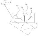
- 3 and 4illustrate a process of aligning the specimen and the ultrasonic sensor for calibration by the automatic calibration device according to the present invention.
- the ultrasonic transducer 51 generating the ultrasonic signal from the ultrasonic sensor 50is installed at a predetermined angle, for example, 60 °, 70 °, and the ultrasonic signal scanned by the ultrasonic transducer 51 is a specimen 210.
- the specimen 210is moved by the XY table 10 so as to be scanned in the same direction as the longitudinal direction (the longitudinal direction in which the crack is formed) of the first crack 211 formed at the bottom surface.
- the X-axis of the specimen 210 by the XY table 10so that the ultrasonic signal generated by the ultrasonic sensor 50 lies on an extension line in the longitudinal direction (the cracked longitudinal direction) of the first crack 211. 5 as shown in FIG. 5 in the direction and Y-axis direction, so that the ultrasonic waves scanned by the ultrasonic sensor 50 lie in the longitudinal extension line of the first crack 211.
- the longitudinal direction (the lengthwise direction in which the crack is formed) of the first crack 211 formed on the specimen 210is different from the scanning direction (same as the X axis direction) of the ultrasonic signal, as shown in FIG.
- the ultrasonic wave scanned by the ultrasonic sensor 50is adjusted to lie in the longitudinal extension line of the first crack 211.
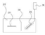
- 5 to 7illustrate a process of scanning and calibrating a defect portion formed on a specimen by the automatic calibration device according to the present invention.
- Ultrasonic sensor 50so that the ultrasonic signal is placed on the extension line in the direction in which the second crack 212 is formed as described above to calibrate the second crack 212 formed in the transverse direction transverse to the longitudinal axis of the specimen 210 Sort it.
- the main controller 60selects the ultrasonic sensor 50 installed in a direction suitable for scanning in the transverse direction transverse to the longitudinal axis of the specimen 210 of the plurality of ultrasonic sensors 50, the second crack 212 As shown in FIG. 6, the center of the ultrasound signal reflected by the second crack 212 is displayed on the screen of the input and display means 70.
- the main controller 60selects a third ultrasonic sensor 50c installed in a direction suitable for scanning in a direction inclined with respect to the longitudinal axis of the specimen 210 among the plurality of ultrasonic sensors 50, and selects the longitudinal axis of the specimen 210.
- the XY table 10 and the turn table 20are moved to calibrate with respect to the third crack 213 formed in the inclined direction transversely so that the ultrasonic signal is placed on an extension line in the direction in which the third crack 213 is formed.
- the third ultrasonic sensor 50cis aligned.
- the main controller 60examines the ultrasonic wave while scanning the ultrasonic wave while moving from side to side, as illustrated in FIG. 7, around the third crack 213, and inputs the level of the ultrasonic signal reflected from the second crack 212. It is displayed on the screen of the display means 70.
- the inspectorlooks at the level of the first to third cracks 211-213 displayed on the input and display means 70, and if the level that does not meet the standard is displayed, the inspector calibrates the ultrasound inspection apparatus 100 so that the reference level comes out. Continue with the calibration process.
- FIG. 8is a flowchart showing a control method of an automatic calibration device for a non-destructive ultrasonic inspection apparatus according to the present invention.
- step S1the main controller 60 checks the specimen by moving the specimen detection sensor 57 to a position corresponding to the position data input by the inspector through the input and display means 70.
- step S2the main controller 60 determines the defective portion (eg, the first crack) of the ultrasonic sensor 50 and the specimen 210 by the position data of the specimen 210 and the position data of the defective portion that the inspector inputs. (211, holes, etc.).
- the alignmentis a process of matching the traveling direction of the ultrasonic signal scanned by the ultrasonic sensor 50 with the longitudinal axis direction of the first crack 211 formed on the specimen 210.
- step S3the main controller 60 checks the scan zero point at which the ultrasonic sensor 50 starts scanning, scans and scans the ultrasonic signal while advancing the ultrasonic sensor 50 toward the defective portion.
- step S4the main controller 60 performs a zigzag scan around the defective portion near the defective portion (for example, the first crack 211, the hole, etc.) (see FIGS. 5 to 7).
- step S5the main controller 60 stores, in the internal memory (not shown), the reflection position where the ultrasonic signal is reflected during the scanning of the defective portion, and in step S6, displays the level of the reflected signal on the input and display means 70. do.
- step S7it is determined whether there is a defective portion to be calibrated next, and if there is, the flow advances to step S2, and if not, the automatic calibration program ends.
Landscapes
- Physics & Mathematics (AREA)
- Health & Medical Sciences (AREA)
- Life Sciences & Earth Sciences (AREA)
- Chemical & Material Sciences (AREA)
- Analytical Chemistry (AREA)
- Biochemistry (AREA)
- General Health & Medical Sciences (AREA)
- General Physics & Mathematics (AREA)
- Immunology (AREA)
- Pathology (AREA)
- Acoustics & Sound (AREA)
- Investigating Or Analyzing Materials By The Use Of Ultrasonic Waves (AREA)
Abstract
Description
Translated fromKorean본 발명은 비파괴 초음파 검사장치용 자동 캘리브레이션 장치 및 그 제어 방법에 관한 것으로, 더욱 상세하게는 검사 중인 파이프 위에 턴 테이블 및 XY 테이블을 설치하고 크랙, 홀 등의 결함부분이 형성된 파이프 시편을 XY 테이블에 올리고 불량상태를 검출하는 신호를 표시하여 초음파 검사장치를 캘리브레이션할 수 있는 비파괴 초음파 검사장치용 자동 캘리브레이션 장치 및 그 제어 방법에 관한 것이다.The present invention relates to an automatic calibration device for a non-destructive ultrasonic inspection apparatus and a control method thereof. More particularly, a pipe specimen having a turn table and an XY table installed on a pipe under inspection and a defect portion such as a crack or a hole is formed on the XY table. An automatic calibration apparatus for a non-destructive ultrasonic inspection apparatus capable of calibrating an ultrasonic inspection apparatus by displaying a signal for detecting a bad state of the oligomer and a control method thereof.
비파괴검사의 초음파검사는 가청음역을 넘는 음파(sound wave), 보통 0.5 ~ 15 Mc 의 주파수인 초음파를 피 검사물에 보내어 내부의 결함 또는 균일하지 못한 층의 존재에 의한 초음파의 진행혼란에 의해서 결함을 검출하는 방법이다.Non-destructive ultrasonography sends sound waves above the audible range, usually ultrasound frequencies of 0.5 to 15 Mc, to the specimen to be inspected by defects caused by internal confusion or by the presence of uneven layers. How to detect.
이 방법은 적당한 두께의 수정판 또는 barium titanate 판의 양 단면에 라디오 주파수의 전기력 진동을 가하면 판이 기계적 진동을 발생하고, 또 반대로 초음파의 기계적 진동을 받으면 양 끝면에 정, 부의 전기를 발생해서 전기진동으로 바뀌는 성질을 이용하여 초음파검사를 하는 방법이다.In this method, electric vibration of radio frequency is applied to both ends of a quartz plate or barium titanate plate of appropriate thickness, and the plate generates mechanical vibration.In contrast, when ultrasonic wave is subjected to mechanical vibration, positive and negative electricity is generated at both ends to generate electric vibration. Ultrasound is a method that uses the changing properties.
초음파는 파장이 짧아서 직진하는 성질이 있고 초음파의 속도는 공기중에서는 330m/s, 물 속에서는 약 1500m/s, 강(鋼)속에서는 약 6000m/s라는 데서 고익와 강의 경계면에서는 초음파는 거의 100% 반사된다.Ultrasonic waves have a short wavelength and go straight. Ultrasonic speed is about 330m / s in air, about 1500m / s in water, and about 6000m / s in river. do.
강(鋼)속으로 초음파를 침입시키는데는 물 또는 글리세린 등을 강의 표면에 칠해서 초음파의 발진용 탐촉자를 접촉시킨다. 그리고 내부의 결함부위에서 초음파가 가장 강하게 반사되는 것을 검출하여 초음파검사를 하게된다.In order to penetrate the ultrasonic wave into the cavity, water or glycerin is coated on the surface of the steel to bring the ultrasonic oscillator into contact. In addition, the ultrasonic wave is detected by detecting the strongest reflection of the ultrasonic wave from the internal defect.
스파이럴 용접 파이프의 용접부에 존재하는 결함은 제품의 수명 단축이나 용접제품의 안전성 저하의 문제를 항상 내포하고 있다. 용접결함을 검출하는 비파괴 검사 방법은 여러가지가 있으나 초음파 탐상법을 이용하여 검사한다.Defects present in the welds of spiral welded pipes always include problems of shortening the life of the product or deteriorating the safety of the welded product. There are many non-destructive testing methods for detecting weld defects, but they are examined using ultrasonic flaw detection.
용접비드에는 혼입된 가스에 의하여 일어나는 핀 호울이나 블로우 호울(blow hole), 응고시의 수축에 의해 일어나는 수축공과 같은 용접 결함이 존재할 수 있다. 이때, 핀 호울 이란 지름이 2-3mm 이하의 기공으로서 보통 다수개가 모여있는 상태로 존재하게 되며, 블로우 호울은 용착금속 내에 생기는 기공으로서, 지름 0.01-3mm 정도까지 여러 가지가 있고, 구형이나 토란형의 구멍으로 되어 있다.The welding beads may have welding defects such as pin holes or blow holes caused by the mixed gas, and shrinkage holes caused by shrinkage during solidification. At this time, the pin hole is a pore having a diameter of 2-3mm or less and usually exists in a state in which a plurality of holes are gathered, and the blow hole is a pore generated in the weld metal. It is a hole of.
초음파를 이용하여 검사하는 방법은 용접부의 한쪽 면만 접근이 가능하면 되고 용접시 발생되는 열, 빛 그리고 전자기장의 영향을 적게 받으므로 장점이 큰 방법이다.The inspection method using ultrasonic waves is advantageous because only one side of the weld can be accessed and is less affected by heat, light and electromagnetic fields generated during welding.
그러나 초음파를 이용하는 경우 모재의 표면에 탐상액을 계속 공급하여 초음파 센서를 밀착시켜야 하는 어려움과 초음파가 온도에 따른 특성변화가 심하다는 제한이 있다.However, in the case of using ultrasonic waves, there are difficulties in that the ultrasonic sensor is closely adhered to the surface of the base material by continuously supplying a flaw solution and the characteristics of the ultrasonic waves are severely changed with temperature.
또한 스파이럴 파이프 생산시 스파이럴 파이프에 형성된 결함을 찾기 위해 초음파로 검사하며 생산한다. 도 9에 파이프의 결함들 또는 흠결들을 갖는 파이프의 개략적인 사시도가 도시된다.In addition, it is produced by inspecting ultrasonically to find the defect formed in the spiral pipe during spiral pipe production. 9 is a schematic perspective view of a pipe having defects or defects of the pipe.
도 9에서 도시된 바와 같이, 파이프(T)에서의 결함들은 그들의 위치에 따라 식별될 수 있다. 따라서, 내측 또는 외측 표면 결함들은, 길이방향 결함들(LD)과 원주(또는 횡단방향 또는 교차 또는 가로방향) 결함들(CD), 그리고 기울어지거나 경사 방향 결함들(ID)을 포함하고, 초음파 감지기들의 여러 배치에 의해, 상기 결함들이 표준 요건들, 규격 요건들, 또는 고객의 요건들(예를 들면, 표준에서 언급된 결함의 길이 값은 검사를 받는 제품의 두께의 대략 5%의 깊이에서 ½ 인치 또는 대략 12.7 mm임)에 따라 정해진 길이와 깊이의 범위를 초과하는 즉시 이들을 검출하려 시도하고 있다.As shown in FIG. 9, defects in the pipe T can be identified according to their position. Accordingly, the inner or outer surface defects include longitudinal defects LD and circumferential (or transverse or intersecting or transverse) defects CD, and tilted or oblique direction defects ID, and the ultrasonic sensor By means of different arrangements, the defects may be standard requirements, specification requirements, or customer requirements (e.g., the length value of the defects mentioned in the standard is ½ at a depth of approximately 5% of the thickness of the product being inspected). Attempts to detect them immediately beyond the range of lengths and depths specified in inches or approximately 12.7 mm).
또한 관심대상인 "파이프 벽에서의" 결함들, 다시 말하면 (도 1에서는 보이지 않는) 덩어리(MD)에서의 결함들이 함유물과 갈라진 말단부들에 형성되는 경우가 많으며, 이들의 검출은 두께의 측정과 함께 시도된다. 결함들의 검출을 설명하기 위하여 초음파 빔들이 도 9에서 한점에 주사하는 것으로 도시되어 있다. 실제로는 초음파 빔들이 거의 한점에 수렴하게 된다.In addition, defects in the "pipe wall" of interest, that is, defects in the mass (not shown in Figure 1), are often formed in the inclusions and cracked distal ends, and their detection is due to the measurement of thickness and Tried together Ultrasonic beams are shown scanning at one point in FIG. 9 to illustrate detection of defects. In practice, the ultrasound beams converge at almost one point.
기존에는, 초음파에 의한 비파괴 검사시, 다음 3가지의 설치 타입들, 즉 이른바 '회전 헤드' 설치 타입, 이른바 '회전 파이프' 설치 타입, 및 다중 요소로 에워싸인 감지기 설치 타입 중의 한가지 타입이 사용되는데, 이러한 설치 타입들 모두는 본 발명이 속하는 기술 분야에서 통상의 지식을 가진 자에게 공지된 것들이다.Conventionally, in the non-destructive inspection by ultrasonic, one of the following three types of installations is used, namely, a 'rotation head' installation type, a so-called 'rotation pipe' installation type, and a detector installation surrounded by multiple elements. All of these installation types are known to those of ordinary skill in the art.
그러나 초음파 검사장치를 이용하여 파이프를 검사하기 위해서는 초음파 검사기와 초음파 센서가 정상적인 상태를 유지하고 있는가를 시험해야 하는 캘리브레이션 (calibration)과정을 8시간마다 하도록 규정되어 있다.However, in order to inspect a pipe using an ultrasonic test apparatus, a calibration process is required every 8 hours to test whether the ultrasonic tester and the ultrasonic sensor are in a normal state.
종래에는 생산라인을 멈추고 캘리브레이션 하기 위한 장비를 설치하고 초음파 검사장치를 캘리브레이션하기 때문에 캘리브레이션 시간이 많이 소요되어서 생산성이 떨어지는 문제점이 있었다.Conventionally, since the installation of the equipment for stopping and calibrating the production line and calibrating the ultrasonic inspection device, the calibration time is consumed a lot, there is a problem that the productivity is lowered.
본 발명은 상기와 같은 문제점을 해결하기 위한 것으로, 본 발명의 목적은 초음파 검사장치의 캘리브레이션(calibration) 과정을 단순화하고 신속하게 할 수있는 비파괴 초음파 검사장치용 자동캘리브레이션 장치 및 그 제어 방법을 제공하는 것이다.The present invention is to solve the above problems, an object of the present invention is to provide an automatic calibration device for a non-destructive ultrasonic inspection apparatus and a control method thereof that can simplify and speed up the calibration (calibration) process of the ultrasonic inspection apparatus. will be.
본 발명의 다른 목적은 캘리브레이션할 수 있는 시편을 다루기 용이한 크기로 제작하고 생산중인 파이프 위에 시편을 회전 및 XY 축 방향으로 이동할 수 있도록 설치하여 간단하고 신속하게 캘리브레이션할 수 있는 비파괴 초음파 검사장치용 자동캘리브레이션 장치 및 그 제어 방법을 제공하는 것이다.Another object of the present invention is to provide a non-destructive ultrasonic inspection device that can be easily and quickly calibrated by manufacturing the specimens that can be calibrated to be easily handled and installed so that the specimens can be rotated and moved in the XY axis direction on the pipe being produced. It is to provide a calibration device and a control method thereof.
상기와 같은 목적을 달성하기 위하여 본 발명에 따른 비파괴 초음파 검사장치용 자동캘리브레이션 장치는 2생산중인 파이프의 위에 고정되어 X축 또는 Y축 방향으로 이동하는 XY 테이블과; 상기 XY 테이블의 위에 회전가능하게 설치되는 턴 테이블과; 상기 턴 테이블 위에 설치되고, 시편을 고정하는 시편 고정판과; 상기 시편에 형성된 결함을 검출하는 다수의 초음파 센서와; 상기 XY 테이블과 턴 테이블 및 Y축 테이블을 제어하여 상기 시편을 이동시켜 상기 초음파 센서가 상기 시편의 결함을 검출하여 입력 및 표시수단에 표시하도록 제어하는 메인 콘트롤러와; 상기 다수의 초음파 센서가 검출한 시편의 결함을 표시하는 입력 및 표시수단을 포함하여 구성되는 것을 특징으로 한다.In order to achieve the above object, an automatic calibration device for a non-destructive ultrasonic inspection apparatus according to the present invention includes an XY table fixed on two pipes being produced and moving in the X-axis or Y-axis direction; A turn table rotatably mounted on the XY table; A specimen fixing plate installed on the turn table to fix the specimen; A plurality of ultrasonic sensors for detecting defects formed in the specimen; A main controller controlling the XY table, the turn table, and the Y-axis table to move the specimen so that the ultrasonic sensor detects a defect of the specimen and displays the input and display means; It characterized in that it comprises an input and display means for displaying a defect of the specimen detected by the plurality of ultrasonic sensors.
본 발명의 일실시예에 의하면 턴 테이블과 시편 고정판 사이에 설치되고, 상기 메인 콘트롤러의 제어에 따라 상기 파이프를 가로지르는 횡방향(Y축 방향)으로 이동하여 상기 시편의 위치를 조정하는 Y축 테이블을 더 구비하는 것을 특징으로 한다.According to an embodiment of the present invention is installed between the turn table and the specimen fixing plate, Y-axis table for adjusting the position of the specimen by moving in the transverse direction (Y-axis direction) across the pipe under the control of the main controller It characterized in that it further comprises.
본 발명의 일실시예에 의하면 XY 테이블은 다수의 힌지가 양끝단에 부착되는 다수의 고정다리를 포함하며 상기 고정다리의 하단에 부착되는 힌지에 의해 결함되는 부착수단에 의해 상기 파이프의 외부 표면에 부착됨으로써 상기 XY 테이블은 상기 파이프에 고정되도록 구성되는 것을 특징으로 한다.According to an embodiment of the present invention, the XY table includes a plurality of fixed legs to which a plurality of hinges are attached to both ends and is attached to the outer surface of the pipe by attachment means that are defective by hinges attached to the lower ends of the fixed legs. By being attached, the XY table is configured to be fixed to the pipe.
본 발명의 일실시예에 의하면 상기 XY 테이블은 사각판 형상으로 형성되는 상판 몸체와; 상기 상판 몸체의 네 모서리에 상부 힌지에 의해 회전 가능하게 설치되고 "ㅅ" 자 모양을 갖는 4개의 고정다리와; 상기 고정다리의 하단부에 하부 힌지에 의해 회전 가능하게 설치되는 부착수단을 포함하여 구성되는 것을 특징으로 한다.According to an embodiment of the present invention, the XY table has a top plate body formed in a rectangular plate shape; Four fixed legs rotatably installed at four corners of the upper plate body by an upper hinge and having a “s” shape; It characterized in that it comprises a mounting means rotatably installed by the lower hinge to the lower end of the fixed leg.
본 발명의 일 실시예에 의하면 상기 XY 테이블의 상판 몸체가 상부 힌지와 4개의 고정다리 및 하부 힌지에 의해 수평을 유지하게 되어 상기 시편 고정판에 고정되는 시편이 수평을 유지하도록 하여 초음파 검사가 안정성 있게 실행될 수 있도록 구성되는 것을 특징으로 한다.According to an embodiment of the present invention, the upper plate body of the XY table is horizontally maintained by the upper hinge, the four fixing legs and the lower hinge so that the specimen fixed to the specimen fixing plate is horizontal so that ultrasonic inspection is stable. And configured to be executable.
본 발명의 일 실시예에 의하면 상기 턴 테이블은 상기 XY 테이블의 상판 몸체 위에 설치되고, 회전축을 중심으로 회전하는 회전 원판과; 상기 회전 원판의 윗면에 일체로 부착되는 사각판 형태의 사각 지지판을 포함하여 구성되는 것을 특징으로 한다.According to an embodiment of the present invention, the turn table is installed on the upper plate body of the XY table, and rotates around a rotation axis; It characterized in that it comprises a rectangular support plate in the form of a square plate integrally attached to the upper surface of the rotating disk.
본 발명의 일 실시예에 의하면 상기 턴 테이블의 회전 원판은 회전한 후 락킹장치에 의해 고정되도록 함으로써 상기 시편을 회전시켜 초음파 센서에서 방사되는 초음파가 결함의 방향에 맞게 입사되도록 조정할 수 있도록 구성되는 것을 특징으로 한다.According to an embodiment of the present invention, the rotating disc of the turn table is configured to be adjusted by the locking device after the rotation by rotating the specimen so that the ultrasonic wave emitted from the ultrasonic sensor is incident to the direction of the defect. It features.
본 발명의 일 실시예에 의하면 상기 시편 고정판은 상기 시편이 수평면에 놓이도록 그 윗면은 편평한 수평면으로 형성되며, "ㄱ" 자 형상의 다수의 고정편이 상기 시편을 고정볼트에 의해 상기 시편 고정판에 고정시키도록 구성되는 것을 특징으로 한다.According to an embodiment of the present invention, the specimen holding plate is formed in a flat horizontal plane so that the specimen is placed on a horizontal plane, and a plurality of “a” shaped fixing pieces are fixed to the specimen holding plate by the fixing bolts. It is characterized in that it is configured to.
본 발명의 일 실시예에 의하면 상기 다수의 초음파 센서는 상기 메인 콘트롤러의 제어에 따라 이동하는 초음파 센서 지지대에 부착된 초음파 센서 지지판에 부착되어 있으며, 상기 메인 콘트롤러의 제어에 의해 초음파를 시편에 주사하고, 시편에 형성된 결함부분에서 반사되는 초음파를 수신하여 상기 메인 콘트롤러에 출력하여 상기 시편에 형성된 결함부분을 검출하도록 구성되는 것을 특징으로 한다.According to an embodiment of the present invention, the plurality of ultrasonic sensors are attached to an ultrasonic sensor support plate attached to an ultrasonic sensor support that moves under the control of the main controller, and injects ultrasonic waves into a specimen under the control of the main controller. And receiving ultrasonic waves reflected from the defect portions formed on the specimen and outputting the ultrasonic waves to the main controller to detect the defect portions formed on the specimen.
본 발명에 따른 비파괴 초음파 검사장치용 자동캘리브레이션 장치의 제어방법은 메인 콘트롤러가 입력 및 표시수단을 통해 검사자가 입력하는 위치 데이타에 해당하는 위치로 시편 검출센서를 이동시켜 시편을 확인하는 단계와; 상기 메인 콘트롤러가 검사자가 입력하는 시편의 위치 데이터와 결함부분에 대한 위치 데이터에 의해 초음파 센서와 시편 결함부분을 정렬하는 단계와; 상기 메인 콘트롤러가 상기 초음파 센서가 스캔을 시작하는 스캔 영점을 확인하고, 상기 검사자가 입력한 결함부분을 향해 초음파 센서를 진행시키면서 초음파 신호를 주사하여 스캔하는 단계와; 상기 메인 콘트롤러가 상기 검사자가 입력한 결함부분 근처에서 상기 결함부분을 중심으로 지그재그 스캔을 실행하는 단계와; 상기 메인 콘트롤러가 상기 결함부분의 스캔 중에 초음파 신호가 반사되는 반사위치를 내장 메모리에 저장하고 반사신호의 레벨을 표시수단에 표시하는 단계를 포함하여 구성되는 것을 특징으로 한다.The control method of the automatic calibration device for a non-destructive ultrasonic inspection apparatus according to the present invention includes the steps of the main controller to check the specimen by moving the specimen detection sensor to a position corresponding to the position data input by the inspector through the input and display means; Aligning, by the main controller, the ultrasonic sensor and the specimen defective portion by the position data of the specimen and the position data of the defect portion input by the inspector; Checking, by the main controller, a scan zero point at which the ultrasonic sensor starts scanning, scanning and scanning an ultrasonic signal while advancing the ultrasonic sensor toward a defective portion input by the inspector; The main controller performing a zigzag scan around the defective portion near the defective portion input by the inspector; And storing, by the main controller, a reflection position where the ultrasonic signal is reflected during the scanning of the defective portion in the internal memory and displaying the level of the reflection signal on the display means.
본 발명에 따른 비파괴 초음파 검사장치용 자동 캘리브레이션 장치에 의하면, 초음파 검사기의 캘리브레이션 장치를 신속하고 정확하게 설치할 수 있어 캘리브레이션의 신뢰성 및 효율성이 향상되는 효과가 있다.According to the automatic calibration device for a non-destructive ultrasonic inspection apparatus according to the present invention, it is possible to quickly and accurately install the calibration device of the ultrasonic scanner has the effect of improving the reliability and efficiency of the calibration.
또한, 시편의 사이즈가 소형이며 휴대가 간편하며 제작이 간단하여 설치가 용이하고 그에 따른 시간이 절약되어 생산성이 향상되는 장점이 있으며, XY 테이블과 턴 테이블에 의해 어느 각도에 설치된 초음파 센서라도 캘리브레이션 할 수 있는 이점이 있다.In addition, the size of the specimen is small, easy to carry and simple to manufacture, it is easy to install and save time accordingly, productivity is improved, and the ultrasonic sensor installed at any angle by XY table and turn table can be calibrated. There is an advantage to this.
도 1은 본 발명에 의한 비파괴 초음파 검사장치용 자동캘리브레이션 장치의 구성을 나타내는 사시도,1 is a perspective view showing the configuration of an automatic calibration device for a non-destructive ultrasonic inspection apparatus according to the present invention;
도 2는 본 발명에 의한 비파괴 초음파 검사장치용 자동캘리브레이션 장치의 구성을 나타내는 정면도,Figure 2 is a front view showing the configuration of the automatic calibration device for non-destructive ultrasonic inspection apparatus according to the present invention,
도 3과 도 4는 본 발명에 의한 자동 캘리브레이션 장치에 의해 캘리브레이션하기 위해 시편과 초음파 센서를 정렬하는 과정,3 and 4 is a process of aligning the specimen and the ultrasonic sensor for calibration by the automatic calibration device according to the present invention,
도 5 내지 도 7은 본 발명에 의한 자동 캘리브레이션 장치에 의해 시편에 형성된 결함부분을 주사하여 캘리브레이션하는 과정,5 to 7 is a process of scanning and calibrating the defect portion formed on the specimen by the automatic calibration device according to the present invention,
도 8은 본 발명에 의한 비파괴 초음파 검사장치용 자동 캘리브레이션 장치의 제어방법을 나타내는 플로우차트,8 is a flowchart showing a control method of an automatic calibration device for a non-destructive ultrasonic inspection apparatus according to the present invention;
도 9는 파이프의 결함들 또는 흠결들을 갖는 파이프의 개략적인 사시도이다.9 is a schematic perspective view of a pipe having defects or defects of the pipe.
이하에서는 도면에 도시된 실시예를 참조하여 본 발명의 구성 및 작용 효과를 상세하게 설명한다.Hereinafter, with reference to the embodiment shown in the drawings will be described in detail the configuration and operation effects of the present invention.
도 1과 도 2에 본 발명에 의한 비파괴 초음파 검사장치용 자동캘리브레이션 장치의 구성을 나타내는 사시도와 정면도가 도시된다.1 and 2 are a perspective view and a front view showing the configuration of an automatic calibration device for a non-destructive ultrasonic inspection apparatus according to the present invention.
본 발명에 따른 비파괴 초음파 검사장치용 자동캘리브레이션 장치(100)는, 생산중인 파이프(200)의 위에 고정되어 메인 콘트롤러(60)의 제어에 의해 X축 또는 Y축 방향으로 이동하는 XY 테이블(10)과; 상기 XY 테이블(10)의 위에 회전가능하게 설치되는 턴 테이블(20)과; 상기 턴 테이블(20)의 위에 설치되어 메인 콘트롤러(60)의 제어에 의해 Y축 방향으로 이동하는 Y축 테이블(30)과; 상기 Y축 테이블(30) 위에 설치되고, 시편(210)을 고정하는 시편 고정판(40)과; 상기 시편(210)에 형성된 크랙, 홀 등의 결함을 검출하는 다수의 초음파 센서(50)와; 상기 XY 테이블(10)을 제어하여 상기 시편(210)을 이동시켜 상기 초음파 센서(50)가 상기 시편(210)의 크랙, 홀 등을 검출하여 입력 및 표시수단(70)에 표시하도록 제어하는 메인 콘트롤러(60)와; 상기 다수의 초음파 센서(50)가 검출한 시편(210)의 결함을 표시하는 입력 및 표시수단(70)를 포함하여 구성된다.The auto-
본 발명에 의한 XY 테이블(10)은 사각판 형상으로 형성되는 상판 몸체(11)와; 상기 상판 몸체(11)의 네 모서리에 상부 힌지(12)에 의해 회전 가능하게 설치되고 "ㅅ" 자 모양을 갖는 4개의 고정다리(13)와; 상기 고정다리(13)의 하단부에 하부 힌지(14)에 의해 회전 가능하게 설치되는 자석 등의 부착수단(15)을 포함하여 구성된다.XY table 10 according to the present invention and the
따라서, XY 테이블(10)은 상부힌지(12)와 하부힌지(14)를 회전시켜 4개의 고정다리(11)를 4개의 부착수단(14)에 의해 파이프(200)의 외부 표면에 부착하면 부착수단(14)의 자력에 의해 접착됨으로써 XY 테이블(10)은 파이프(200)에 고정된다.Therefore, the XY table 10 is attached by rotating the
XY 테이블(10)의 상판 몸체(11)는 평편한 사각판 형태로 형성되어 파이프(200)의 윗면에 놓이게 되면 도 2에 도시된 바와 같이 파이프(200)의 외주원에 접하게 되고, 상판 몸체(11)는 네 모서리에 설치된 상부 힌지(12)와 4개의 고정다리(13) 및 하부 힌지(14)에 의해 수평을 유지한 상태로 파이프(200)의 윗면에 고정된다.The
4개의 고정다리(13)는 파이프(200)의 외주원에 외접하도록 상부 힌지(12)와 하부 힌지(14)에 의해 회전 가능하게 설치되고 "ㅅ" 자 모양을 갖기 때문에 상판 몸체(11)는 둥그런 파이프(200)의 외주원에 수평으로 외접한 상태에서 4개의 고정다리(13)의 각도를 상부 힌지(12)와 하부 힌지(14)에 의해 2번 조정하여 파이프(200)의 외주원에 접하여 부착됨으로써 상판 몸체(11)는 수평을 유지한 상태에서 파이프(200)에 고정될 수 있다.Since the four
XY 테이블(10)의 상판 몸체(11)가 상부 힌지(12)와 4개의 고정다리(13) 및 하부 힌지(14)에 의해 수평을 유지하게 되어 시편 고정판(40)에 고정되는 시편(210)이 수평을 유지하도록 하여 초음파 검사가 안정성 있게 실행될 수 있다.The
턴 테이블(20)은 XY 테이블(10)의 상판 몸체(11) 위에 설치되고, 회전축(도시생략)을 중심으로 회전하는 회전 원판(21)과; 상기 회전 원판(21)의 윗면에 일체로 부착되는 사각판 형태의 사각 지지판(22)을 포함하여 구성된다.The turn table 20 is provided on the
턴 테이블(20)의 회전 원판(21)은 회전한 후 락킹장치(도시 생략) 예를 들면, 회전 원판(21)에 형성된 톱니에 고정핀이 걸리도록 구성되는 락킹장치에 의해 고정되도록 함으로써 시편(210)을 회전시켜 초음파 센서(50)에서 방사되는 초음파가 크랙의 방향에 맞게 입사되도록 조정할 수 있다.The
회전원판(21)의 지름은 XY 테이블(10)의 상판 몸체(11)보다 작게 형성될 수 있으며, 회전원판(21) 위에 설치되는 사각 지지판(22)은 파이프(200)를 가로지르는 횡방향(Y축 방향)으로 더 길게 형성되는 직사각형의 판으로 형성된다.The diameter of the
Y축 테이블(30)은 턴 테이블(20) 위에 형성되고, 메인 콘트롤러(60)의 제어에 따라 파이프(200)를 가로지르는 횡방향(Y축 방향)으로 이동하여 시편(210)의 위치를 조정한다.The Y-axis table 30 is formed on the turn table 20, and moves in the horizontal direction (Y-axis direction) across the
시편 고정판(40)은 Y축 테이블(30) 위에 고정되며 시편(210)이 수평면에 놓이도록 그 윗면은 편평한 수평면으로 형성되며, "ㄱ" 자 형상의 다수의 고정편(41)이 시편(210)을 고정볼트(41a)에 의해 시편 고정판(40)에 고정시킨다.
다수의 초음파 센서(50)는 메인 콘트롤러(60)의 제어에 따라 이동하는 초음파 센서 지지대(56)에 부착된 초음파 센서 지지판(55)에 부착되어 있으며, 메인 콘트롤러(60)의 제어에 의해 초음파를 시편(210)에 주사하고, 시편(210)에 형성된 결함부분에서 반사되는 초음파를 수신하여 메인 콘트롤러(60)에 출력하여 시편(210)에 형성된 결함부분을 검출한다.The plurality of
초음파 센서 지지판(55)에 시편(210)을 검출하기 위한 시편 검출센서(57)가 설치되어 있으며, 시편 검출센서(57)는 레이저 센서, 초음파 센서 또는 전자파 센서등으로 구성될 수 있으며, 메인 콘트롤러(60)의 제어에 따라 시편(210)의 위치를 검출하여 검출신호를 상기 메인 콘트롤러(60)로 출력한다.
메인 콘트롤러(60)는 초음파 검사장치(200)에 내장되며 XY 테이블(10)을 제어하여 시편(210)을 이동시키면서 상기 초음파 센서(50)에서 주사되어 시편(210)의 결함부(예를 들면, 크랙, 홀 등)에서 반사되어 감지되는 초음파 신호를 입력받아 입력 및 표시수단(70)에 표시한다.The
입력 및 표시수단(70)은 터치 스크린, 모니터 등일 수 있으며, 메인 콘트롤러(60)의 제어에 따라 초음파 센서(50)에서 주사되어 시편(210)의 결함부에서 반사되어 감지된 신호를 화면에 표시한다.The input and display means 70 may be a touch screen, a monitor, or the like. The input and display means 70 may be scanned by the
도 3과 도 4에 본 발명에 의한 자동 캘리브레이션 장치에 의해 캘리브레이션하기 위해 시편과 초음파 센서를 정렬하는 과정을 나타낸다.3 and 4 illustrate a process of aligning the specimen and the ultrasonic sensor for calibration by the automatic calibration device according to the present invention.
초음파 센서(50)에서 초음파 신호를 발생시키는 초음파 트랜스듀서(51)는 예를 들면, 60°, 70° 등 일정한 각도로 설치되어 있으며, 초음파 트랜스듀서(51)에서 주사되는 초음파 신호는 시편(210)에 형성된 제1 크랙(211)의 종방향(크랙이 형성된 길이방향)과 동일한 방향으로 주사되도록 XY 테이블(10)에 의해 시편(210)을 이동시킨다.The
예를 들면, 초음파 센서(50)에서 발생되는 초음파 신호가 제1 크랙(211)의 종방향(크랙이 형성된 길이방향)의 연장선에 놓이도록 XY 테이블(10)에 의해 시편(210)을 X축 방향과 Y축 방향으로 도 5에 도시된 바와 같이 이동시켜 초음파 센서(50)에서 주사되는 초음파가 제1 크랙(211)의 종방향의 연장선에 놓이도록 한다.For example, the X-axis of the
또한 시편(210)에 형성된 제1 크랙(211)의 종방향(크랙이 형성된 길이방향)이 초음파 신호의 주사방향(X 축방향과 동일)과 다른 경우, 도 4에 도시된 바와 같이 턴 테이블(20)에 의해 시편(210)을 화살표 방향으로 회전시켜 초음파 센서(50)에서 주사되는 초음파가 제1 크랙(211)의 종방향의 연장선에 놓이도록 조정한다.In addition, when the longitudinal direction (the lengthwise direction in which the crack is formed) of the
도 5 내지 도 7에 본 발명에 의한 자동 캘리브레이션 장치에 의해 시편에 형성된 결함부분을 주사하여 캘리브레이션하는 과정을 나타낸다.5 to 7 illustrate a process of scanning and calibrating a defect portion formed on a specimen by the automatic calibration device according to the present invention.
시편(210)의 종축과 동일한 방향으로 형성된 제 1 크랙(211)을 주사하여 캘리브레이션 하기 위해 도 5에 도시된 바와 같이 초음파 센서(50)에서 시편(210)의 종축의 연장선에 주사하면서 지그재그로 또는 제 1 크랙(211)을 중심으로 위와 아래로 일정한 거리 이동하면서 진행하면서 제1 크랙(211)에서 반사되는 초음파 신호를 감지하여 입력 및 표시수단(70)에 표시한다.In order to scan and calibrate the
시편(210)의 종축에 대해 가로지르는 횡방향으로 형성된 제 2크랙(212)에 대해 캘리브레이션하기 위해 앞서와 같이 제 2 크랙(212)이 형성된 방향의 연장선에 초음파 신호가 놓이도록 초음파 센서(50)를 정렬한다.
이때 메인 콘트롤러(60)는 다수의 초음파 센서(50) 중에서 시편(210)의 종축에 대해 가로지르는 횡방향으로 주사하기 적합한 방향에 설치된 초음파 센서(50)를 선택하고, 제 2 크랙(212)을 중심으로 도 6에 도시된 바와 같이 좌우로 이동하면서 검사하여 제 2 크랙(212)에서 반사되는 초음파 신호의 레벨을 입력 및 표시수단(70)의 화면에 표시한다.At this time, the
메인 콘트롤러(60)는 다수의 초음파 센서(50) 중에서 시편(210)의 종축에 대해 경사진 방향으로 주사하기 적합한 방향에 설치된 제3 초음파 센서(50c)를 선택하고, 시편(210)의 종축에 대해 가로지르는 경사진 방향으로 형성된 제 3 크랙(213)에 대해 캘리브레이션하기 위해 XY 테이블(10) 및 턴 테이블(20)을 이동시켜 제 3 크랙(213)이 형성된 방향의 연장선에 초음파 신호가 놓이도록 상기 제 3 초음파 센서(50c)를 정렬한다.The
이어서 메인 콘트롤러(60)는 제 3 크랙(213)을 중심으로 도 7에 도시된 바와 같이 좌우로 이동하면서 초음파를 주사하면서 검사하고, 제 2 크랙(212)에서 반사되는 초음파 신호의 레벨을 입력 및 표시수단(70)의 화면에 표시한다.Subsequently, the
검사자는 입력 및 표시수단(70)에 표시되는 제1 내지 제3 크랙(211-213)의 레벨을 보고 기준에 미치지 못하는 레벨이 표시되면 기준 레벨이 나오도록 초음파 검사장치(100)를 캘리브레이션 하고 다음의 캘리브레이션 작업을 계속 진행한다.The inspector looks at the level of the first to third cracks 211-213 displayed on the input and display means 70, and if the level that does not meet the standard is displayed, the inspector calibrates the
도 8에 본 발명에 의한 비파괴 초음파 검사장치용 자동 캘리브레이션 장치의 제어방법을 나타내는 플로우차트가 도시된다.8 is a flowchart showing a control method of an automatic calibration device for a non-destructive ultrasonic inspection apparatus according to the present invention.
단계 S1에서, 메인 콘트롤러(60)는 입력 및 표시수단(70)을 통해 검사자가 입력하는 위치 데이타에 해당하는 위치로 시편 검출센서(57)를 이동시켜 시편을 확인한다. 단계 S2에서, 메인 콘트롤러(60)는 검사자가 입력하는 시편(210)의 위치 데이터와 결함부분에 대한 위치 데이터에 의해 초음파 센서(50)와 시편(210)의 결함부분(예를 들면 제1 크랙(211), 홀 등)을 정렬한다.In step S1, the
여기서 정렬은 초음파 센서(50)에서 주사되는 초음파 신호의 진행방향과 시편(210)에 형성된 제1 크랙(211)의 종축 방향을 일치시키는 과정이다.In this case, the alignment is a process of matching the traveling direction of the ultrasonic signal scanned by the
단계 S3에서, 메인 콘트롤러(60)는 초음파 센서(50)가 스캔을 시작하는 스캔 영점을 확인하고, 결함부분을 향해 초음파 센서(50)를 진행시키면서 초음파 신호를 주사하여 스캔한다.In step S3, the
단계 S4에서, 메인 콘트롤러(60)는 결함부분(예를 들면 제1 크랙(211), 홀 등) 근처에서 결함부분을 중심으로 지그재그 스캔을 실행한다(도 5 내지 도 7 참조).In step S4, the
단계 S5에서, 메인 콘트롤러(60)는 결함부분의 스캔 중에 초음파 신호가 반사되는 반사위치를 내장 메모리(도시생략)에 저장하고 단계 S6에서, 반사신호의 레벨을 입력 및 표시수단(70)에 표시한다.In step S5, the
단계 S7에서, 다음 캘리브레이션할 결함부분이 있는지를 판단하고, 있는 경우 단계 S2로 진행하고 없는 경우 본 자동 캘리브레이션 프로그램을 종료한다.In step S7, it is determined whether there is a defective portion to be calibrated next, and if there is, the flow advances to step S2, and if not, the automatic calibration program ends.
앞에서 설명되고, 도면에 도시된 실시예는 본 발명을 실시하기 위한 하나의 실시예에 불과하며, 본 발명의 기술적 사상을 한정하는 것으로 해석되어서는 안된다. 본 발명의 보호범위는 이하의 특허청구범위에 기재된 사항에 의해서만 정하여지며, 본 발명의 요지를 벗어남이 없이 개량 및 변경된 실시예는 본 발명이 속하는 기술분야에서 통상의 지식을 가진 자에게 자명한 것인 한 본 발명의 보호범위에 속한다.The embodiments described above and illustrated in the drawings are only one embodiment for carrying out the present invention, and should not be construed as limiting the technical spirit of the present invention. The scope of protection of the present invention is defined only by the matters set forth in the claims below, and the embodiments which have been improved and changed without departing from the gist of the present invention will be apparent to those skilled in the art. It belongs to the protection scope of the present invention.
Claims (10)
Translated fromKoreanApplications Claiming Priority (2)
| Application Number | Priority Date | Filing Date | Title |
|---|---|---|---|
| KR10-2015-0104335 | 2015-07-23 | ||
| KR20150104335 | 2015-07-23 |
Publications (1)
| Publication Number | Publication Date |
|---|---|
| WO2017014344A1true WO2017014344A1 (en) | 2017-01-26 |
Family
ID=57834459
Family Applications (1)
| Application Number | Title | Priority Date | Filing Date |
|---|---|---|---|
| PCT/KR2015/007782CeasedWO2017014344A1 (en) | 2015-07-23 | 2015-07-27 | Automatic calibration device for non-destructive ultrasound inspection device, and control method therefor |
Country Status (1)
| Country | Link |
|---|---|
| WO (1) | WO2017014344A1 (en) |
Cited By (6)
| Publication number | Priority date | Publication date | Assignee | Title |
|---|---|---|---|---|
| CN107102064A (en)* | 2017-06-24 | 2017-08-29 | 东北石油大学 | A kind of automatic outer detection means of pipe ultrasonic |
| CN110658213A (en)* | 2019-09-30 | 2020-01-07 | 合肥公共安全技术研究院 | Nondestructive testing device for detecting three-dimensional defects on surface of seamless steel pipe |
| CN114935607A (en)* | 2022-06-06 | 2022-08-23 | 武汉岩海工程技术有限公司 | Calibration device with protective structure for nonmetal ultrasonic detector |
| CN115856083A (en)* | 2023-02-27 | 2023-03-28 | 中国汽车技术研究中心有限公司 | Method, device, equipment and medium for testing performance of skin of automobile collision dummy |
| CN117434163A (en)* | 2023-12-20 | 2024-01-23 | 中煤科工开采研究院有限公司 | Calibration device and method for acoustic emission sensor |
| CN118254202A (en)* | 2024-05-28 | 2024-06-28 | 济宁市质量计量检验检测研究院(济宁半导体及显示产品质量监督检验中心、济宁市纤维质量监测中心) | Handle robot and method for nondestructive testing of underwater pipeline |
Citations (5)
| Publication number | Priority date | Publication date | Assignee | Title |
|---|---|---|---|---|
| JP2003215113A (en)* | 2002-01-28 | 2003-07-30 | Hitachi Kenki Fine Tech Co Ltd | Ultrasonic imaging apparatus |
| KR20090036285A (en)* | 2007-10-09 | 2009-04-14 | 현대자동차주식회사 | Non-destructive inspection device for electron beam welding of laser-guided ultrasonic method and its inspection method |
| KR20090067554A (en)* | 2007-12-21 | 2009-06-25 | 조선대학교산학협력단 | Simple one-way ultrasonic property evaluation automation system |
| KR20100110376A (en)* | 2008-02-26 | 2010-10-12 | 가부시끼가이샤 도시바 | Ultrasonic inspection device |
| KR20100124242A (en)* | 2010-11-08 | 2010-11-26 | 주식회사 삼영검사엔지니어링 | Calibration block (reference block) and calibration procedure for phased-array ultrasonic inspection |
- 2015
- 2015-07-27WOPCT/KR2015/007782patent/WO2017014344A1/ennot_activeCeased
Patent Citations (5)
| Publication number | Priority date | Publication date | Assignee | Title |
|---|---|---|---|---|
| JP2003215113A (en)* | 2002-01-28 | 2003-07-30 | Hitachi Kenki Fine Tech Co Ltd | Ultrasonic imaging apparatus |
| KR20090036285A (en)* | 2007-10-09 | 2009-04-14 | 현대자동차주식회사 | Non-destructive inspection device for electron beam welding of laser-guided ultrasonic method and its inspection method |
| KR20090067554A (en)* | 2007-12-21 | 2009-06-25 | 조선대학교산학협력단 | Simple one-way ultrasonic property evaluation automation system |
| KR20100110376A (en)* | 2008-02-26 | 2010-10-12 | 가부시끼가이샤 도시바 | Ultrasonic inspection device |
| KR20100124242A (en)* | 2010-11-08 | 2010-11-26 | 주식회사 삼영검사엔지니어링 | Calibration block (reference block) and calibration procedure for phased-array ultrasonic inspection |
Cited By (8)
| Publication number | Priority date | Publication date | Assignee | Title |
|---|---|---|---|---|
| CN107102064A (en)* | 2017-06-24 | 2017-08-29 | 东北石油大学 | A kind of automatic outer detection means of pipe ultrasonic |
| CN110658213A (en)* | 2019-09-30 | 2020-01-07 | 合肥公共安全技术研究院 | Nondestructive testing device for detecting three-dimensional defects on surface of seamless steel pipe |
| CN110658213B (en)* | 2019-09-30 | 2021-11-26 | 合肥公共安全技术研究院 | Nondestructive testing device for detecting three-dimensional defects on surface of seamless steel pipe |
| CN114935607A (en)* | 2022-06-06 | 2022-08-23 | 武汉岩海工程技术有限公司 | Calibration device with protective structure for nonmetal ultrasonic detector |
| CN115856083A (en)* | 2023-02-27 | 2023-03-28 | 中国汽车技术研究中心有限公司 | Method, device, equipment and medium for testing performance of skin of automobile collision dummy |
| CN117434163A (en)* | 2023-12-20 | 2024-01-23 | 中煤科工开采研究院有限公司 | Calibration device and method for acoustic emission sensor |
| CN117434163B (en)* | 2023-12-20 | 2024-04-16 | 中煤科工开采研究院有限公司 | Calibration device and method for acoustic emission sensor |
| CN118254202A (en)* | 2024-05-28 | 2024-06-28 | 济宁市质量计量检验检测研究院(济宁半导体及显示产品质量监督检验中心、济宁市纤维质量监测中心) | Handle robot and method for nondestructive testing of underwater pipeline |
Similar Documents
| Publication | Publication Date | Title |
|---|---|---|
| WO2017014344A1 (en) | Automatic calibration device for non-destructive ultrasound inspection device, and control method therefor | |
| CN100507550C (en) | Method of Ultrasonic Detecting Wing | |
| CN101672829A (en) | Method for measuring parameter of omega welding seam defect | |
| CN109425618B (en) | Optical measurement system and method | |
| CN116068045B (en) | Composite structure defect identification method for inhibiting lift-off effect interference | |
| WO2018182103A1 (en) | Defect detection device and defect detection method using same | |
| JP2013088242A (en) | Ultrasonic testing method and ultrasonic testing apparatus | |
| CN102565188B (en) | Ultrasonic detecting equipment | |
| JPH04230847A (en) | Ultrasonic testing apparatus and testing method for quickly inspecting internal defect of neck shoulder of similarly designed gas cylinder | |
| WO2020111526A1 (en) | Probe for nondestructive inspection apparatus using intersecting gradient-type induced currents, and method for manufacturing induction coil for nondestructive inspection apparatus | |
| ES2861349T3 (en) | Ultrasonic examination of components with unknown surface geometries | |
| KR20170010922A (en) | System for monitoring breakage of glass substrate | |
| WO2023245964A1 (en) | Phased array ultrasonic testing apparatus and method for bolt hole crack | |
| JP7057196B2 (en) | Ultrasonic flaw detection method and equipment | |
| CN117761162A (en) | Wind power spindle ultrasonic reflection echo comparison detection method | |
| JPH10288605A (en) | Magnetic testing device and method | |
| JP2749021B2 (en) | Automatic ultrasonic flaw detector | |
| CN112326798B (en) | Ultrasonic detection method for crane T-shaped weld joint region defects | |
| JP2023077632A (en) | Inspection device and inspection method | |
| WO2016017991A1 (en) | Nondestructive fatigue inspection apparatus and inspection method therefor using electromagnetic induction sensor | |
| JP5323005B2 (en) | Ultrasonic flaw detector and control method thereof | |
| JPS61191960A (en) | Ultrasonic inspection of tube or bar material | |
| JPH11281591A (en) | Apparatus and method for evaluating interior quality of dielectric material product | |
| JPH06118068A (en) | Nondestructive inspection device and method for material | |
| CN111487314B (en) | Scanning method based on ultrasonic detection |
Legal Events
| Date | Code | Title | Description |
|---|---|---|---|
| 121 | Ep: the epo has been informed by wipo that ep was designated in this application | Ref document number:15898992 Country of ref document:EP Kind code of ref document:A1 | |
| NENP | Non-entry into the national phase | Ref country code:DE | |
| 122 | Ep: pct application non-entry in european phase | Ref document number:15898992 Country of ref document:EP Kind code of ref document:A1 |