WO2017010160A1 - Handheld electric power tool - Google Patents
Handheld electric power toolDownload PDFInfo
- Publication number
- WO2017010160A1 WO2017010160A1PCT/JP2016/064356JP2016064356WWO2017010160A1WO 2017010160 A1WO2017010160 A1WO 2017010160A1JP 2016064356 WJP2016064356 WJP 2016064356WWO 2017010160 A1WO2017010160 A1WO 2017010160A1
- Authority
- WO
- WIPO (PCT)
- Prior art keywords
- drive
- state
- motor
- power tool
- control unit
- Prior art date
- Legal status (The legal status is an assumption and is not a legal conclusion. Google has not performed a legal analysis and makes no representation as to the accuracy of the status listed.)
- Ceased
Links
Images


Classifications
- H—ELECTRICITY
- H02—GENERATION; CONVERSION OR DISTRIBUTION OF ELECTRIC POWER
- H02J—CIRCUIT ARRANGEMENTS OR SYSTEMS FOR SUPPLYING OR DISTRIBUTING ELECTRIC POWER; SYSTEMS FOR STORING ELECTRIC ENERGY
- H02J7/00—Circuit arrangements for charging or depolarising batteries or for supplying loads from batteries
- H02J7/0029—Circuit arrangements for charging or depolarising batteries or for supplying loads from batteries with safety or protection devices or circuits
- H02J7/0031—Circuit arrangements for charging or depolarising batteries or for supplying loads from batteries with safety or protection devices or circuits using battery or load disconnect circuits
- H02J7/0032—Circuit arrangements for charging or depolarising batteries or for supplying loads from batteries with safety or protection devices or circuits using battery or load disconnect circuits disconnection of loads if battery is not under charge, e.g. in vehicle if engine is not running
- B—PERFORMING OPERATIONS; TRANSPORTING
- B25—HAND TOOLS; PORTABLE POWER-DRIVEN TOOLS; MANIPULATORS
- B25F—COMBINATION OR MULTI-PURPOSE TOOLS NOT OTHERWISE PROVIDED FOR; DETAILS OR COMPONENTS OF PORTABLE POWER-DRIVEN TOOLS NOT PARTICULARLY RELATED TO THE OPERATIONS PERFORMED AND NOT OTHERWISE PROVIDED FOR
- B25F5/00—Details or components of portable power-driven tools not particularly related to the operations performed and not otherwise provided for
- B25F5/02—Construction of casings, bodies or handles
- H—ELECTRICITY
- H01—ELECTRIC ELEMENTS
- H01H—ELECTRIC SWITCHES; RELAYS; SELECTORS; EMERGENCY PROTECTIVE DEVICES
- H01H9/00—Details of switching devices, not covered by groups H01H1/00 - H01H7/00
- H01H9/02—Bases, casings, or covers
- H01H9/06—Casing of switch constituted by a handle serving a purpose other than the actuation of the switch, e.g. by the handle of a vacuum cleaner
- H—ELECTRICITY
- H02—GENERATION; CONVERSION OR DISTRIBUTION OF ELECTRIC POWER
- H02J—CIRCUIT ARRANGEMENTS OR SYSTEMS FOR SUPPLYING OR DISTRIBUTING ELECTRIC POWER; SYSTEMS FOR STORING ELECTRIC ENERGY
- H02J7/00—Circuit arrangements for charging or depolarising batteries or for supplying loads from batteries
- H02J7/0029—Circuit arrangements for charging or depolarising batteries or for supplying loads from batteries with safety or protection devices or circuits
- H02J7/0036—Circuit arrangements for charging or depolarising batteries or for supplying loads from batteries with safety or protection devices or circuits using connection detecting circuits
- H—ELECTRICITY
- H02—GENERATION; CONVERSION OR DISTRIBUTION OF ELECTRIC POWER
- H02J—CIRCUIT ARRANGEMENTS OR SYSTEMS FOR SUPPLYING OR DISTRIBUTING ELECTRIC POWER; SYSTEMS FOR STORING ELECTRIC ENERGY
- H02J7/00—Circuit arrangements for charging or depolarising batteries or for supplying loads from batteries
- H02J7/0029—Circuit arrangements for charging or depolarising batteries or for supplying loads from batteries with safety or protection devices or circuits
- H02J7/00306—Overdischarge protection
Definitions
- This disclosurerelates to a hand-held power tool such as an electric chain saw, an electric marnoco, and an electric blower.
- the hand-held power toolis provided with a grip for the user to hold and operate.
- the gripis provided with a trigger switch so that the user can operate with a finger while holding the grip.
- the hand-held power toolhas a built-in motor as a power source and a control unit for driving and controlling the motor, and the control unit drives and controls the motor according to the operation of the trigger switch by the user.
- a built-in motoras a power source
- a control unitfor driving and controlling the motor
- the control unitdrives and controls the motor according to the operation of the trigger switch by the user.
- the controllercan drive the motor at any time when connected to a battery or a commercial power source, the motor is driven against the user's intention due to an erroneous operation of the trigger switch or the like. Sometimes it is not easy to use.
- a main power switch for switching permission / prohibition of motor driveis provided separately from the trigger switch, and the user switches the main power switch to the off state, It may be possible to prohibit driving.
- control unitdrives and controls the motor according to the operation of the trigger switch until the user switches the main power switch from the on state to the off state.
- the trigger switchis erroneously operated. It is conceivable that the motor is driven.
- a hand-held power toolin a hand-held power tool, it is desirable that even if a user forgets to operate the main power switch, it is possible to prevent the motor from being driven by an erroneous operation of the trigger switch.
- a hand-held power toolincludes a motor, a trigger switch, a main power switch, and a control unit.
- the trigger switch and the main power switchare for external operation by the user, the trigger switch is used to input a motor drive command, and the main power switch is a motor drive permission / prohibition switch Used to input commands.
- the control unitswitches its operation mode between a drive permission state for permitting motor driving and a drive prohibition state for prohibiting motor driving in accordance with a switching command from the main power switch. And in a drive permission state, drive control of a motor is performed according to the drive command input from a trigger switch.
- control unitis configured to switch its own operation mode to a drive prohibited state when the drive of the motor is stopped in accordance with the stop of the input of the drive command from the trigger switch. For this reason, in the hand-held power tool of one aspect of the present disclosure, when the operation mode of the control unit is in the drive-permitted state, the user operates the trigger switch to drive the motor, and then operates the trigger switch. When the operation is finished, the operation mode of the control unit is automatically switched to the drive prohibited state.
- the motorwhen the user operates the trigger switch to perform a desired work, the motor is driven even if the user operates the trigger switch thereafter. None happen. Therefore, according to this indication, it can control that a motor drives against a user's intention, and can improve the usability of a hand-held power tool.
- the main power switch and the trigger switchare arranged at separate positions so that the user does not turn on at the same time just by gripping the power tool.
- both the main power switch and the trigger switchare turned on, and the operation mode of the control unit is switched to the drive-permitted state, contrary to the user's intention. At the same time, the driving of the motor can be suppressed.
- the main power switchmay be provided in the main body in which the motor is accommodated, and the trigger switch may be provided in a gripping portion that protrudes from the main body and is gripped by the user when the electric tool is used.
- the main power switchby operating the main power switch by extending the finger of the hand holding the gripping part to the main body side, or by operating the main power switch on the main body side with a hand not gripping the gripping part.
- the personcan operate the main power switch while holding the holding part (in other words, the state where the trigger switch can be operated).
- the hand-held power toolis configured in this way, not only can the main power switch and the trigger switch be turned on against the user's intention, but also the operation of these switches becomes difficult. It can suppress that the operativity of a hand-held power tool falls.
- the hand-held power toolmay include a notification unit for notifying the operation state of the power tool.
- the control unitdetermines whether or not the state of the electric tool is normal, and if the electric tool is in an abnormal state, the operation mode is either the drive permission state or the drive prohibition state.
- the abnormality of the power toolmay be notified via the notification unit.
- the usercan identify whether or not the cause is due to the abnormality (failure) of the electric tool. Can be improved.
- this technologycan be applied even to an electric tool that is not configured to switch the operation mode to the drive prohibited state when the control unit stops driving the motor in response to the stop of input of the drive command from the trigger switch. it can.
- the present inventioncan also be applied to an electric tool in which a main power switch and a trigger switch are provided in a grip portion and can be operated simultaneously with one hand by a user.
- the notification unitdisplays 1 whether the operation mode of the control unit is the drive permission state or the drive inhibition state.
- a plurality of display lampsmay be provided.
- control unitis configured to notify the abnormality of the electric tool by switching the lighting state of the display lamp to a lighting state different from the driving permission state and the driving prohibition state when determining the abnormality of the electric tool. It may be.
- control unitdetermines whether or not the plurality of states of the electric tool are normal, and any of the plurality of states is abnormal. If determined to be, the content of the determined abnormality may be notified via a notification unit.
- control unitwhen the control unit notifies the abnormality of the power tool via the notification unit when the operation mode is in the drive prohibited state, if the preset notification stop condition is satisfied, the control unit detects an abnormality from the notification unit. You may be comprised so that alerting
- the notification stop conditionmay be when the notification time of abnormality when the operation mode of the control unit is in the drive prohibited state reaches a predetermined time set in advance.
- the battery voltage of the battery that supplies power to the electric toolmay be lowered to a preset threshold voltage.
- itmay be when a notification stop command is input from the user by an external operation, or a combination thereof.
- the trigger switchmay be provided with a lock release unit for fixing the trigger switch to the non-operation position and releasing the position fixation by an external operation.
- a lock release unitfor fixing the trigger switch to the non-operation position and releasing the position fixation by an external operation.
- the trigger switchcannot be operated unless the lock release unit is operated, erroneous operation of the trigger switch can be suppressed more favorably.
- it is possible to suppress the motor from being driven by the erroneous operationit is possible to suppress wasteful power consumption associated with the motor driving.
- FIG. 3Ais an explanatory diagram for explaining the status display using the status display unit
- FIG. 3Bis an explanatory diagram for explaining the status display using the remaining amount display unit.
- Itis a flowchart showing the control processing performed with the control circuit of FIG.
- Itis a flowchart showing the motor drive permission management process performed in S130 of FIG.
- Itis a flowchart showing the motor control process performed in S160 of FIG.
- Itis a flowchart showing the display process performed in S170 of FIG.
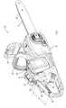
- the chain saw 2 of this embodimentis a kind of hand-held power tool, and includes a guide bar 6 having a saw chain 3 attached to the periphery thereof, and a main body 4 having a guide bar 6 protruding therefrom. Prepare.
- the guide bar 6is for supporting the saw chain 3 together with a sprocket (not shown) in the main body 4 so that the saw chain 3 can rotate, and the saw chain 3 is driven in the main body 4 by rotating the sprocket.
- the motor 10(refer FIG. 2) is accommodated.
- the main body 4is provided with a first grip 12 and a second grip 14 for the user to hold with the left and right hands, respectively.
- the first grip 12protrudes from the front center of the main body 4 when the guide bar 6 protrudes from the main body 4 in the forward direction.
- a hand guard 16 connected to a stop mechanism (not shown)is provided.
- a pair of battery packs 8are detachably fixed to the left and right side walls behind the first grip 12 of the main body 4, and the second grip 14 projects rearward from the mounting portion of the battery pack 8. It is provided as follows.
- the trigger switchis positioned at a position where the user can operate the gripper (A) shown in FIG. (Hereinafter referred to as trigger SW) 18 is provided. Specifically, the trigger SW 18 is provided below the protruding portion from the main body 4 of the grip portion (A).
- the trigger SW 18is turned on when operated by a user, and is a well-known one configured to be able to output a signal corresponding to the amount of operation.
- the trigger SW 18is a motor drive unit 30 housed in the main body 4 together with the motor 10. It is connected to the control circuit 36 (see FIG. 2).
- a lock release lever 19is provided on the side opposite to the trigger SW 18 (specifically, above the protruding part of the gripping part (A) from the main body 4). ing.
- the lock release lever 19corresponds to an example of the lock release portion of the present disclosure, and is engaged with the trigger SW 18 in the second grip 14 (or the main body 4) to fix the trigger SW 18 to the non-operation position (lock). ) When the lock release lever 19 is pressed toward the second grip 14 by the user, the engagement with the trigger SW 18 is released and the trigger SW 18 can be operated.
- the trigger SW 18can be operated with a fingertip if the second grip 14 is grasped while holding the lock release lever 19 from above, but if the lock release lever 19 is not pressed, the trigger SW is It can not be operated.
- an operation panel 20is provided on a portion of the upper wall surface of the main body 4 where the second grip 14 protrudes rearward. Further, a remaining amount display unit 24 for displaying the remaining amount of the battery 9 in the battery pack 8 (the amount of electric power remaining in the battery 9) is provided further forward than the operation panel 20.
- main power SWmain power switch
- status display unit 22for displaying operation / stop of the chainsaw 2 (specifically, permission / prohibition of driving of the motor 10 by the control circuit 36). And are assembled.
- the main power SW 21, the status display unit 22, and the remaining amount display unit 24are also connected to the control circuit 36 of the motor drive unit 30 (see FIG. 2).
- the state display unit 22 and the remaining amount display unit 24correspond to an example of the notification unit of the present disclosure.
- the state display unit 22is a so-called power lamp, and is connected to one LED. Configured.
- the remaining amount display unit 24is configured by three LEDs so that the remaining amount of the battery can be recognized from the lighting state.
- the motor drive unit 30is for receiving power supply from the battery 9 in the battery pack 8 to drive and control the motor 10, and as shown in FIG. 2, a drive circuit 32, a gate circuit 34, a control circuit 36, And a regulator 40.
- the drive circuit 32is for receiving electric power from the battery 9 and for causing a current to flow through each phase winding of the motor 10.
- the drive circuit 32is a three-phase full bridge circuit including six switching elements Q1 to Q6. It is configured as. Note that each of the switching elements Q1 to Q6 is a MOSFET in this embodiment.
- the three switching elements Q1 to Q3are provided as so-called high-side switches between the terminals U, V, and W of the motor 10 and the power supply line connected to the positive side of the battery 9. Yes.
- the other three switching elements Q4 to Q6are provided as so-called low-side switches between the terminals U, V, W of the motor 10 and the ground line connected to the negative electrode side of the battery 9.
- the gate circuit 34turns on / off the switching elements Q1 to Q6 in the drive circuit 32 according to the control signal output from the control circuit 36, thereby causing a current to flow through each phase winding of the motor 10 and the motor. 10 is rotated.
- control circuit 36is constituted by a microcomputer including a CPU, ROM, RAM and the like.
- the control circuit 36is also provided with a non-volatile memory 38 for storing the state (abnormality or the like) of the motor 10 or the motor drive unit 30 to be controlled.
- the control circuit 36is connected to the above-described trigger SW 18, main power supply SW 21, status display unit 22, and remaining amount display unit 24. Further, the motor drive unit 30 is provided with a battery voltage detection unit 42 that detects a battery voltage, a current detection circuit 44 that detects a current that flows through the motor 10, and a temperature sensor 48 that detects the temperature of the motor drive unit 30. These parts are also connected to the control circuit 36.
- the motor 10is provided with a rotation sensor 46 for detecting the rotation position and rotation speed of the motor 10, and this rotation sensor 46 is also connected to the control circuit 36.
- the battery pack 8also has a monitoring circuit (not shown) that monitors the state of the battery 9 (temperature, cell voltage, etc.) and outputs a stop signal AS (autostop) that stops discharging from the battery 9 when an abnormality occurs.
- the control circuit 36is also connected to this monitoring circuit.
- the control circuit 36changes the operation mode to the drive permission state in which energization to the motor 10 is permitted, and to the motor 10. Is switched to one of the drive prohibition states in which energization is prohibited.
- the control circuit 36lights the LED of the state display unit 22 when the operation mode is the drive permission state, and turns on the LED of the state display unit 22 when the operation mode is the drive inhibition state. Turn off the LED.
- the userlooks at the LED (status display unit 22) of the display panel 20 to determine whether the control circuit 36 is in a drive permission state in which the motor 10 can be driven or in a drive prohibition state in which the motor 10 cannot be driven ( In other words, the operation / stop state of the chainsaw 2 can be recognized.
- the control circuit 36operates the chainsaw 2 by controlling the drive of the motor 10 according to the operation amount.
- control circuit 36is configured based on detection signals from the battery voltage detection unit 42, the current detection circuit 44, the rotation sensor 46, and the temperature sensor 48, and the motor 10, the motor drive unit 30 and the control circuit 36. It is determined whether or not the battery pack 8 is normal.
- the control circuit 36also monitors the input of the stop signal AS from the battery pack 8 separately from such abnormality determination (hereinafter referred to as error determination) when the operation mode is the drive permission state.
- control circuit 36When the control circuit 36 detects any abnormality by the error determination or monitoring of the stop signal AS, the control circuit 36 stops driving the motor 10 and uses the three LEDs of the remaining amount display unit 24 to indicate the detected error content. To inform.
- control circuit 36configures the remaining amount display unit 24 as illustrated in FIG. 3B if the motor 10, the motor drive unit 30, and the battery pack 8 are normal when the operation mode is the drive permission state.
- the three LEDsare turned on by the number corresponding to the remaining battery level.
- the control circuit 36sets all three LEDs constituting the remaining amount display unit 24. Turn off the light. For this reason, the user can recognize from the states of the state display unit 22 and the remaining amount display unit 24 that the drive is currently prohibited and no error has occurred in the chainsaw 2.
- the control circuit 36displays the remaining amount display unit 24. This is notified by turning on the left LED and blinking the remaining LEDs.
- the control circuit 36blinks the LED on the left side of the remaining amount display unit 24 and displays the remaining LEDs. This is notified by turning off the light.
- control circuit 36starts reporting (displaying) the error content
- the control circuit 36continues to report the error content even when the operation mode is switched from the drive permitted state to the drive prohibited state. Therefore, when an error occurs in the chainsaw 2, the user can determine the occurrence of the error and the details of the error from the state of the remaining amount display section 24 regardless of whether the control circuit 36 is in the drive permitted state or the drive prohibited state. Can be recognized.
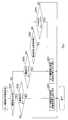
- control circuit 36repeatedly executes a series of processes from S120 to S160 (S represents a step) in a predetermined control cycle (time base).
- control circuit 36determines whether or not the time base has elapsed in S110, waits for a predetermined control period to elapse, and determines that the time base has elapsed in S110 and proceeds to S120. Transition.
- the switch operation detection process for detecting the operation of each switch by the useris executed by confirming the signal input from the trigger SW 18 and the main power source SW21.
- a motor drive permission management processis executed to set the operation mode of the control circuit itself to either the drive permitted state or the drive prohibited state based on the operation state of each switch detected in S120.
- an A / D conversion processis performed in which the operation amount of the trigger SW 18 and the detection results by the battery voltage detection unit 42, the current detection circuit 44, and the temperature sensor 48 are A / D converted and captured.
- S160a motor control process for controlling the drive of the motor 10 according to the operation amount of the trigger SW 18 is executed.
- the operation mode set in S130is the drive prohibited state
- the power supply from the battery 9 to the gate circuit 34is cut off, and the switching elements Q1 to Q6 in the drive circuit 32 are turned off. By doing so, the drive of the motor 10 is stopped.
- S160the driving of the motor 10 is also stopped when an abnormality is detected in S150 during the driving of the motor 10. And if a motor control process is performed in S160, it will transfer to S170, a display process will be performed, and it will transfer to S110.
- the remaining amount display unit 24displays the remaining battery amount, the drive permission / prohibition state, the presence / absence of an error in the chainsaw 2, and the error contents. It is processing of.
- the motor drive permission management process executed in S130will be described. As shown in FIG. 5, in the motor drive permission management process, first, in S210, it is determined whether or not the current operation mode is a drive prohibited state. If the drive is prohibited, the process proceeds to S220, and it is determined whether the main power supply SW21 is operated and the operation mode is switched.
- S260it is determined whether or not the elapsed time from when the operation mode of the control circuit 36 is switched to the drive-permitted state until the trigger SW 18 is operated and turned on is equal to or longer than a preset specified time. .
- the processproceeds to S250, and the control circuit The operation mode 36 is set to the drive prohibited state, and the motor drive permission management process is terminated.
- the motor drive permission management processends. If it is determined in S270 that the trigger SW 18 has not been switched from the on state to the off state, the process ends. If it is determined in S270 that the trigger SW 18 has been switched from the on state to the off state, the process proceeds to S250, and the motor drive permission management process is performed after setting the operation mode of the control circuit 36 to the drive prohibited state. finish.
- the processproceeds to S320, and it is determined whether or not the trigger SW 18 is on. If the trigger SW 18 is not on, the motor drive stop process of S350 is executed to end the motor control process. If the trigger SW 18 is on, the process proceeds to S330.
- S430it is determined whether or not there is no error in the error detection process in S150. If it is determined that there is no error, the process proceeds to S460. If it is not determined that there is no error, the process proceeds to S440.
- S440it is determined whether or not the battery voltage detected by the battery voltage detection unit 42 is equal to or higher than a preset threshold (in other words, display lower limit voltage) for preventing overdischarge. If the battery voltage is lower than the threshold value, all the LEDs of the remaining amount display unit 24 are turned off in S420, and then the display process is terminated. If the battery voltage is equal to or higher than the threshold value, the process proceeds to S450.
- a preset thresholdin other words, display lower limit voltage
- the error contentis displayed (notified) by blinking the LED of the remaining amount display unit 24 in accordance with the error content detected in the error detection process.
- S450as illustrated in FIG. 3B, not only the LED of the remaining amount display section 24 blinks but also various LEDs detected by the error detection process by turning on / off the LEDs other than the blinking LED. Displays error details.
- S460it is determined whether or not the operation mode is currently in a drive-permitted state. If the drive is not permitted (in other words, if the drive is prohibited), the process proceeds to S420, and all the LEDs of the remaining amount display unit 24 are turned off, and then the display process is terminated.
- the processproceeds to S470, and as shown in FIG. 3B, the remaining battery level indicator 24 is turned on according to the remaining battery level to display (notify) the remaining battery level.
- the display processends.
- the operation of the trigger SW 18is stopped, the driving of the motor 10 is stopped and the driving is prohibited. Therefore, according to the chainsaw 2 of the present embodiment, after the user operates the trigger SW 18 to perform a desired work, the operation mode is automatically switched to the drive prohibited state, and then the user triggers Even if the SW 18 is operated, the driving of the motor 10 is stopped.
- the chainsaw 2 of the present embodimenteven if the user erroneously operates the trigger SW 18 after performing the work, the motor 10 is not driven and the usability can be improved. Further, the trigger SW 18 is provided in a grip portion (A) of the second grip 14 that protrudes from the main body 4 and grips when the user uses the chainsaw 2. For this reason, it can be easily operated while the user grips the grip portion (A) of the second grip 14 (in other words, when the chainsaw 2 is used).
- the main power supply SW21is provided not on the grip portion (A) of the second grip 14 but on the upper wall surface of the main body 4 from which the grip portion (A) projects. For this reason, the user only holds the second grip 14 to carry the chainsaw 2, the trigger SW 18 and the main power supply SW 21 are simultaneously turned on, and the motor 10 is not driven.
- the main The power supply SW21can be operated.
- the main power SW 21can also be operated using a hand opposite to the hand that holds the gripping part (A).
- the userwhen the user grips the grip portion (A) of the second grip 14 in order to use the chainsaw 2, the user can not only operate the trigger SW 18, but can also operate the main power source SW21 if he / she wants to operate it. .
- the chainsaw 2 of the present embodimentnot only can the main power supply SW21 and the trigger SW18 be prevented from being turned on against the user's intention, but also the operation of these switches is difficult. It can suppress that the operativity of the chainsaw 2 falls.
- the control circuit 36when an abnormality occurs in the motor 10 or the motor drive unit 30 or the battery pack 8 to be controlled when the control circuit 36 is in the drive permission state, the control circuit 36 notifies that effect. Detected and displayed on the remaining amount display unit 24. The error display continues even when the drive is prohibited.
- the error contentis notified in an identifiable manner by a combination of lighting, blinking, and extinguishing of three LEDs provided in the remaining amount display unit 24. For this reason, the user can grasp the error content from the display state of the remaining amount display unit 24 and can take an appropriate action.
- the motor 10when the trigger SW 18 is operated to drive the motor 10, the motor 10 cannot be driven even if the trigger SW 18 is operated thereafter, but in this case, the drive is prohibited. Thus, all the LEDs of the remaining amount display unit 24 are turned off. Therefore, it can be confirmed from the display state of the remaining amount display section 24 that the motor 10 cannot be driven by the operation of the trigger SW 18 (in other words, the drive prohibited state).
- the display timeis limited. Even if the display time does not reach the time limit, when the battery voltage becomes less than the threshold value, the error display is switched to a display indicating that the drive is prohibited (that is, all LEDs are turned off).
- the second grip 14 provided with the trigger SW 18is provided with a lock release lever 19 that can be pressed when the user grips it.
- the lock release lever 19is pressed, the trigger SW 18 is turned on. It can be operated.
- the trigger SW 18cannot be operated unless the lock release lever 19 is operated (pressed). With this configuration, erroneous operation of the trigger SW 18 can be suppressed better. Can do.
- control circuit 36corresponds to an example of the control unit of the present disclosure
- the status display unit 22 and the remaining amount display unit 24correspond to an example of the notification unit of the present disclosure.
- this indicationis not limited to the above-mentioned embodiment, and can take various modes within the range which does not deviate from the gist of this indication.
- the chain saw 2provided so that the second grip 14 provided with the trigger SW 18 protrudes rearward of the main body 4 has been described.
- the present disclosurecan be configured in the same manner as in the above embodiment even when the second grip 14 is a chainsaw 2a provided above the main body 4 as illustrated in FIG.
- the battery pack 8is attached to the rear end of the main body 4, and the second grip 14 straddles the attachment portion and the front main body portion from which the guide bar 6 protrudes. It is provided as follows.
- the second grip 14has a substantially entire region in the front-rear direction serving as a grip portion (A) that the user grips when the chainsaw 2 is used, and the trigger SW 18 is provided on the lower front side of the grip portion (A). Yes.
- a lock release button 19a having the same function as the lock release lever 19is provided as a lock release portion on the side wall of the grip portion (A) where the trigger SW 18 is provided.
- An operation panel 20 having a main power supply SW21is assembled on the upper wall surface of the main body 4 from which the second grip 14 protrudes rearward, and a single LED serving as a status display unit 22 is provided further forward. It has been.
- the main power supply SW21is disposed at a position (that is, the main body 4 side) that cannot be operated simply by gripping the grip portion (A) of the second grip 14.
- the main power supply SW21 and the trigger SW18are turned on at the same time only by holding the holding portion (A) of the second grip 14 against the user's intention.
- the motor in the main body 4is not driven.
- the main power supply SW21can be operated by extending the finger (thumb or the like) of the hand holding the holding part (A), it is possible to suppress the operability of the chainsaw 2 from being lowered as in the above embodiment.
- the chain saw 2a shown in FIG. 8is only provided with a status display unit 22 consisting of a single LED as a notification unit.
- the (drive permission / prohibition state) and the error statemay be notified.
- the main power supply SW21is provided on the upper wall surface of the main body 4 near the second grip 14. However, the position of the main power supply SW21 is determined by the user. Any position that can be reached if the finger is extended with the gripping portion (A) held. For this reason, the main power supply SW21 may be provided on the side wall of the main body 4, for example.
- the error displaywhen an error display is performed in the drive prohibited state, the error display is limited based on the display time and the battery voltage. However, the error is stopped by a notification stop command from the user. The display may be stopped.
- the notification stop commandmay be input by an operation of the trigger SW 18 or the main power source SW 21 (for example, a short-time operation, the number of times of the operation), or other information provided in the remaining amount display unit 24. Input may be performed by operating a switch.
- the LEDs provided in the status display unit 22 and the remaining amount display unit 24are used to notify the main power supply state and the error state.
- the notification unitmay be a display unit configured by a single display lamp made of LEDs or the like, such as the status display unit 22.
- the display lampis turned on in the drive permitted state, the display lamp is turned off in the drive prohibited state, and the display lamp blinks when an error is detected, the operation state of the electric tool (drive permitted / prohibited state). And an error state can be notified.
- the error contentcan be notified by the blinking cycle and the number of times of the display lamp.
- the remaining amount display unit 24may be configured by a plurality of display lamps composed of LEDs or the like. Even in this case, the operation state (drive permission / prohibition state) and various error states of the electric tool can be notified by changing the display form (lighting, extinguishing, blinking) of each display lamp.
- the main power SW 21is described as a push button type.
- the main power SW 21may be a slide type switch or a switch capable of self-holding the ON / OFF state of the contact. May be.
- the hand-held power toolmay be a rechargeable power tool that receives power from a battery pack, or a power tool that operates by receiving AC power from a commercial power source.
Landscapes
- Engineering & Computer Science (AREA)
- Mechanical Engineering (AREA)
- Power Engineering (AREA)
- Portable Power Tools In General (AREA)
- Control Of Electric Motors In General (AREA)
Abstract
Description
Translated fromJapanese本国際出願は、2015年7月13日に日本国特許庁に出願された日本国特許出願第2015-139874号に基づく優先権を主張するものであり、日本国特許出願第2015-139874号の全内容を参照により本国際出願に援用する。This international application claims priority based on Japanese Patent Application No. 2015-139874 filed with the Japan Patent Office on July 13, 2015, and is based on Japanese Patent Application No. 2015-139874. The entire contents are incorporated herein by reference.
本開示は、例えば、電動チェーンソー、電動マルノコ、電動ブロワー等の手持ち式電動工具に関する。This disclosure relates to a hand-held power tool such as an electric chain saw, an electric marnoco, and an electric blower.
手持ち式電動工具には、使用者が手で持ち、操作するためのグリップが設けられている。また、グリップには、使用者がグリップを把持した状態で、指で操作できるようにトリガスイッチが設けられている。The hand-held power tool is provided with a grip for the user to hold and operate. In addition, the grip is provided with a trigger switch so that the user can operate with a finger while holding the grip.
また、手持ち式電動工具には、動力源となるモータや、モータを駆動制御するための制御部が内蔵されており、制御部は、使用者によるトリガスイッチの操作に応じて、モータを駆動制御する(例えば、特許文献1参照)。In addition, the hand-held power tool has a built-in motor as a power source and a control unit for driving and controlling the motor, and the control unit drives and controls the motor according to the operation of the trigger switch by the user. (For example, refer to Patent Document 1).
ところで、手持ち式電動工具においては、バッテリ若しくは商用電源に接続されているときに制御部がいつでもモータを駆動できるようにすると、トリガスイッチの誤操作等により使用者の意図に反してモータが駆動されることがあり、使い勝手が悪い。By the way, in a hand-held power tool, if the controller can drive the motor at any time when connected to a battery or a commercial power source, the motor is driven against the user's intention due to an erroneous operation of the trigger switch or the like. Sometimes it is not easy to use.
このため、手持ち式電動工具においては、トリガスイッチとは別に、例えば、モータの駆動許可・禁止を切り替えるための主電源スイッチを設け、使用者が主電源スイッチをオフ状態に切り替えることで、モータの駆動を禁止できるようにすることが考えられる。For this reason, in the hand-held power tool, for example, a main power switch for switching permission / prohibition of motor drive is provided separately from the trigger switch, and the user switches the main power switch to the off state, It may be possible to prohibit driving.
しかしながら、このような対策では、使用者によって主電源スイッチがオン状態からオフ状態に切り替えられるまでは、制御部は、トリガスイッチの操作に応じてモータを駆動制御することになる。However, with such a countermeasure, the control unit drives and controls the motor according to the operation of the trigger switch until the user switches the main power switch from the on state to the off state.
このため、例えば、使用者が主電源スイッチを操作し忘れ、主電源スイッチがオフ状態に切り替えられていないときに、手持ち式電動工具を移動させようとしてグリップを握ると、トリガスイッチが誤操作されて、モータが駆動されてしまうことが考えられる。For this reason, for example, if the user forgets to operate the main power switch and the main power switch is not switched to the OFF state, if the user grasps the grip to move the hand-held power tool, the trigger switch is erroneously operated. It is conceivable that the motor is driven.
本開示の一局面では、手持ち式電動工具において、使用者が主電源スイッチを操作し忘れても、トリガスイッチの誤操作によりモータが駆動されるのを抑制できることが望ましい。In one aspect of the present disclosure, in a hand-held power tool, it is desirable that even if a user forgets to operate the main power switch, it is possible to prevent the motor from being driven by an erroneous operation of the trigger switch.
本開示の一局面の手持ち式電動工具は、モータと、トリガスイッチと、主電源スイッチと、制御部とを備える。
トリガスイッチと主電源スイッチは、使用者が外部から操作するためのものであり、トリガスイッチは、モータの駆動指令を入力するのに用いられ、主電源スイッチは、モータの駆動許可・禁止の切り替え指令を入力するのに用いられる。A hand-held power tool according to one aspect of the present disclosure includes a motor, a trigger switch, a main power switch, and a control unit.
The trigger switch and the main power switch are for external operation by the user, the trigger switch is used to input a motor drive command, and the main power switch is a motor drive permission / prohibition switch Used to input commands.
制御部は、主電源スイッチからの切り替え指令に従い、自身の動作モードを、モータの駆動を許可する駆動許可状態と、モータの駆動を禁止する駆動禁止状態との何れかに切り替える。そして、駆動許可状態では、トリガスイッチから入力される駆動指令に従いモータを駆動制御する。The control unit switches its operation mode between a drive permission state for permitting motor driving and a drive prohibition state for prohibiting motor driving in accordance with a switching command from the main power switch. And in a drive permission state, drive control of a motor is performed according to the drive command input from a trigger switch.
また制御部は、トリガスイッチからの駆動指令の入力停止に伴いモータの駆動を停止すると、自身の動作モードを駆動禁止状態に切り替えるように構成されている。
このため、本開示の一局面の手持ち式電動工具においては、制御部の動作モードが駆動許可状態であるとき、使用者がトリガスイッチを操作して、モータを駆動させた後、トリガスイッチの操作を終了すると、制御部の動作モードが駆動禁止状態に自動で切り替えられる。In addition, the control unit is configured to switch its own operation mode to a drive prohibited state when the drive of the motor is stopped in accordance with the stop of the input of the drive command from the trigger switch.
For this reason, in the hand-held power tool of one aspect of the present disclosure, when the operation mode of the control unit is in the drive-permitted state, the user operates the trigger switch to drive the motor, and then operates the trigger switch. When the operation is finished, the operation mode of the control unit is automatically switched to the drive prohibited state.
従って、本開示の一局面の手持ち式電動工具によれば、使用者が、トリガスイッチを操作して所望の作業を実施すると、その後、使用者がトリガスイッチを操作しても、モータが駆動されることはない。よって、本開示によれば、使用者の意図に反してモータが駆動されるのを抑制することができ、手持ち式電動工具の使い勝手を向上できる。Therefore, according to the hand-held power tool of one aspect of the present disclosure, when the user operates the trigger switch to perform a desired work, the motor is driven even if the user operates the trigger switch thereafter. Never happen. Therefore, according to this indication, it can control that a motor drives against a user's intention, and can improve the usability of a hand-held power tool.
また特に、本開示の一局面では、主電源スイッチとトリガスイッチとが、使用者が当該電動工具を把持しただけで同時にオン状態となることのないよう、離れた位置に配置されている。Also, in particular, in one aspect of the present disclosure, the main power switch and the trigger switch are arranged at separate positions so that the user does not turn on at the same time just by gripping the power tool.
このため、使用者が手持ち式電動工具を持ち運ぶとき等に、使用者の意図に反して、主電源スイッチとトリガスイッチとの両方がオン状態となり、制御部の動作モードが駆動許可状態に切り替えられると同時にモータが駆動されるのを抑制できる。For this reason, when the user carries the hand-held power tool, both the main power switch and the trigger switch are turned on, and the operation mode of the control unit is switched to the drive-permitted state, contrary to the user's intention. At the same time, the driving of the motor can be suppressed.
この場合、主電源スイッチは、モータが収納された本体に設けられ、トリガスイッチは、本体から突出されて当該電動工具の使用時に使用者が把持するための把持部に設けられていてもよい。In this case, the main power switch may be provided in the main body in which the motor is accommodated, and the trigger switch may be provided in a gripping portion that protrudes from the main body and is gripped by the user when the electric tool is used.
このようにすれば、使用者は、電動工具を使用するために把持部を把持してトリガスイッチを操作する際、制御部を駆動禁止状態から駆動許可状態に切り替えて、モータを駆動できるようにするには、主電源スイッチを意識的に操作する必要がある。In this way, when the user grips the grip portion and operates the trigger switch to use the electric tool, the user can drive the motor by switching the control portion from the drive prohibition state to the drive permission state. To do this, it is necessary to consciously operate the main power switch.
つまり、把持部を把持した手の指を本体側に伸ばして主電源スイッチを操作するか、或いは、把持部を把持していない手で本体側の主電源スイッチを操作するようにすれば、使用者は、把持部を把持した状態(換言すればトリガスイッチを操作できる状態)で、主電源スイッチを操作することができる。In other words, it is possible to use the main power switch by operating the main power switch by extending the finger of the hand holding the gripping part to the main body side, or by operating the main power switch on the main body side with a hand not gripping the gripping part. The person can operate the main power switch while holding the holding part (in other words, the state where the trigger switch can be operated).
よって、手持ち式電動工具をこのように構成すれば、主電源スイッチとトリガスイッチとが使用者の意図に反してオン状態となるのを抑制できるだけでなく、これら各スイッチの操作がし難くなって、手持ち式電動工具の操作性が低下するのを抑制できる。Therefore, if the hand-held power tool is configured in this way, not only can the main power switch and the trigger switch be turned on against the user's intention, but also the operation of these switches becomes difficult. It can suppress that the operativity of a hand-held power tool falls.
次に、本開示の一局面の手持ち式電動工具は、電動工具の動作状態を報知するための報知部を備えていてもよい。この場合、制御部は、当該電動工具の状態が正常であるか否かを判定して、当該電動工具が異常状態であれば、動作モードが駆動許可状態及び駆動禁止状態の何れであっても、報知部を介して当該電動工具の異常を報知するよう構成されていてもよい。Next, the hand-held power tool according to one aspect of the present disclosure may include a notification unit for notifying the operation state of the power tool. In this case, the control unit determines whether or not the state of the electric tool is normal, and if the electric tool is in an abnormal state, the operation mode is either the drive permission state or the drive prohibition state. The abnormality of the power tool may be notified via the notification unit.
このようにすれば、一般的な電動工具のように、制御部が通常の動作状態(換言すれば、駆動許可状態)であるときに異常状態が報知されるだけでなく、制御動作停止状態(換言すれば、駆動禁止状態)であるときにも異常状態が報知されることになる。In this way, as in a general electric tool, when the control unit is in a normal operation state (in other words, a drive permission state), not only an abnormal state is notified, but also a control operation stop state ( In other words, the abnormal state is notified even when the drive is prohibited.
従って、使用者は、トリガスイッチを操作してもモータが駆動されない場合に、その原因は、電動工具の異常(故障)によるものであるのか否かを識別することができ、電動工具の使い勝手を向上できる。Therefore, when the motor is not driven even when the trigger switch is operated, the user can identify whether or not the cause is due to the abnormality (failure) of the electric tool. Can be improved.
また、このように、制御部の動作モードが駆動禁止状態であるときに電動工具の異常状態を報知するようにすれば、使用者は、トリガスイッチの操作によってモータを駆動できないときに、その原因を認識することができる。In this way, when the operation mode of the control unit is in the drive prohibited state, if the abnormal state of the electric tool is notified, the user cannot drive the motor by operating the trigger switch. Can be recognized.
従って、この技術は、制御部が、トリガスイッチからの駆動指令の入力停止に伴いモータの駆動を停止したときに動作モードを駆動禁止状態に切り替えるように構成されていない電動工具であっても適用できる。Therefore, this technology can be applied even to an electric tool that is not configured to switch the operation mode to the drive prohibited state when the control unit stops driving the motor in response to the stop of input of the drive command from the trigger switch. it can.
また、同様に、例えば、主電源スイッチとトリガスイッチとが把持部に設けられていて、使用者が片手で同時操作できる電動工具であっても適用できる。
次に、上記のように報知部を介して電動工具の異常を報知する場合、報知部は、制御部の動作モードが駆動許可状態であるのか駆動禁止状態であるのかを表示するための1又は複数の表示ランプを備えていてもよい。Similarly, for example, the present invention can also be applied to an electric tool in which a main power switch and a trigger switch are provided in a grip portion and can be operated simultaneously with one hand by a user.
Next, when notifying the abnormality of the electric tool via the notification unit as described above, the notification unit displays 1 whether the operation mode of the control unit is the drive permission state or the drive inhibition state. A plurality of display lamps may be provided.
この場合、制御部は、電動工具の異常を判定すると、表示ランプの点灯状態を、駆動許可状態及び駆動禁止状態とは異なる点灯状態に切り替えることで、当該電動工具の異常を報知するよう構成されていてもよい。In this case, the control unit is configured to notify the abnormality of the electric tool by switching the lighting state of the display lamp to a lighting state different from the driving permission state and the driving prohibition state when determining the abnormality of the electric tool. It may be.
また、上記のように報知部を介して電動工具の異常を報知する場合、制御部は、電動工具の複数の状態が正常であるか否かを判定して、複数の状態の何れかが異常であると判定すると、その判定した異常の内容を、報知部を介して報知するよう構成されていてもよい。Further, when notifying the abnormality of the electric tool via the notification unit as described above, the control unit determines whether or not the plurality of states of the electric tool are normal, and any of the plurality of states is abnormal. If determined to be, the content of the determined abnormality may be notified via a notification unit.
また、制御部は、動作モードが駆動禁止状態であるときに、報知部を介して当該電動工具の異常を報知する際には、予め設定された報知停止条件が成立すると、報知部からの異常報知を停止するよう構成されていてもよい。In addition, when the control unit notifies the abnormality of the power tool via the notification unit when the operation mode is in the drive prohibited state, if the preset notification stop condition is satisfied, the control unit detects an abnormality from the notification unit. You may be comprised so that alerting | reporting may be stopped.
このようにすれば、駆動禁止状態であるときに、報知部を介して電動工具の異常を報知することによって消費される消費電力を抑制することができる。
なお、報知停止条件としては、制御部の動作モードが駆動禁止状態であるときの異常の報知時間が予め設定された規定時間に達したときであってもよい。また、当該電動工具に電源供給を行うバッテリのバッテリ電圧が予め設定された閾値電圧まで低下したときであってもよい。また、外部操作によって使用者から報知停止指令が入力されたときであってもよいし、これらの組み合わせであってもよい。If it does in this way, when it is a drive prohibition state, the power consumption consumed by alerting | reporting abnormality of an electric tool via an alerting | reporting part can be suppressed.
Note that the notification stop condition may be when the notification time of abnormality when the operation mode of the control unit is in the drive prohibited state reaches a predetermined time set in advance. The battery voltage of the battery that supplies power to the electric tool may be lowered to a preset threshold voltage. Moreover, it may be when a notification stop command is input from the user by an external operation, or a combination thereof.
一方、トリガスイッチには、トリガスイッチを非操作位置に固定し、外部操作によってその位置固定を解除するためのロック解除部が設けられていてもよい。
この場合、トリガスイッチは、ロック解除部を操作しなければ操作できないことから、トリガスイッチの誤操作をより良好に抑制することができる。また、その誤操作によりモータが駆動されるのを抑制できるので、モータ駆動に伴う無駄な電力消費を抑えることもできる。On the other hand, the trigger switch may be provided with a lock release unit for fixing the trigger switch to the non-operation position and releasing the position fixation by an external operation.
In this case, since the trigger switch cannot be operated unless the lock release unit is operated, erroneous operation of the trigger switch can be suppressed more favorably. In addition, since it is possible to suppress the motor from being driven by the erroneous operation, it is possible to suppress wasteful power consumption associated with the motor driving.
2,2a…チェーンソー、3…ソーチェーン、4…本体、6…ガイドバー、8…バッテリパック、9…バッテリ、10…モータ、12…第1グリップ、14…第2グリップ、16…ハンドガード、18…トリガSW、19,19a…ロック解除レバー、20…操作パネル、21…主電源SW、22…状態表示部、24…残量表示部、30…モータ駆動部、32…駆動回路、34…ゲート回路、36…制御回路、38…メモリ、40…レギュレータ、42…バッテリ電圧検出部、44…電流検出回路、46…回転センサ、48…温度センサ。2, 2a ... chainsaw, 3 ... saw chain, 4 ... main body, 6 ... guide bar, 8 ... battery pack, 9 ... battery, 10 ... motor, 12 ... first grip, 14 ... second grip, 16 ... hand guard, DESCRIPTION OF
以下に本開示の実施形態を図面と共に説明する。
図1に示すように、本実施形態のチェーンソー2は、手持ち式電動工具の一種であり、周囲にソーチェーン3が取り付けられたガイドバー6と、ガイドバー6が突設された本体4とを備える。Hereinafter, embodiments of the present disclosure will be described with reference to the drawings.
As shown in FIG. 1, the chain saw 2 of this embodiment is a kind of hand-held power tool, and includes a
ガイドバー6は、本体4内のスプロケット(図示せず)と共にソーチェーン3を周回可能に支持するためのものであり、本体4内には、スプロケットを回転させることによってソーチェーン3を周回駆動するモータ10(図2参照)が収納されている。The
また、本体4には、使用者が左右の手でそれぞれ把持するための第1グリップ12及び第2グリップ14が設けられている。
第1グリップ12は、本体4からのガイドバー6の突出方向を前方としたとき、本体4の前後方向中央上部に突設されており、第1グリップ12の更に前方には、モータ10の緊急停止機構(図示せず)に接続されたハンドガード16が設けられている。Further, the
The
また、本体4の第1グリップ12よりも後方の左右の側壁には、一対のバッテリパック8が着脱自在に固定されており、第2グリップ14は、バッテリパック8の装着部から後方に突出するよう設けられている。A pair of
第2グリップ14において、使用者がチェーンソー2を使用する際に把持する把持部(図1に示す領域A)には、その把持部(A)を把持した手で操作可能な位置に、トリガスイッチ(以下、トリガSWという)18が設けられている。具体的には、トリガSW18は、把持部(A)の本体4からの突出部下方に設けられている。In the
トリガSW18は、使用者により操作されるとオン状態となり、その操作量に応じた信号を出力可能に構成された周知のものであり、モータ10と共に本体4内に収納されたモータ駆動部30の制御回路36に接続されている(図2参照)。The
また、第2グリップ14の把持部(A)において、トリガSW18とは反対側(具体的には、把持部(A)の本体4からの突出部上方)には、ロック解除レバー19が設けられている。Further, on the gripping part (A) of the
ロック解除レバー19は、本開示のロック解除部の一例に相当するものであり、第2グリップ14(若しくは本体4)内でトリガSW18に係合されて、トリガSW18を非操作位置に固定(ロック)する。そして、ロック解除レバー19は、使用者により第2グリップ14側に押下されると、トリガSW18との係合が外れ、トリガSW18が操作可能となる。The
従って、本実施形態のチェーンソー2においては、上方からロック解除レバー19を押さえつつ第2グリップ14を把持すれば、トリガSW18を指先で操作できるが、ロック解除レバー19を押さえなければ、トリガSWは操作できない。Therefore, in the
なお、こうしたロック解除レバー19については、電動工具において周知であるため、詳細な構成は説明を省略する。
次に、本体4の上部壁面で、第2グリップ14が後方に突出される部分には、操作パネル20が設けられている。また、操作パネル20よりも更に前方側には、バッテリパック8内のバッテリ9の残量(バッテリ9に残っている電力量)を表示するための残量表示部24が設けられている。Since such a
Next, an
操作パネル20には、主電源スイッチ(以下、主電源SWという)21と、チェーンソー2の動作・停止(詳しくは制御回路36によるモータ10の駆動許可・禁止)を表示するための状態表示部22とが組み付けられている。On the
そして、主電源SW21、状態表示部22、及び、残量表示部24も、モータ駆動部30の制御回路36に接続されている(図2参照)。
なお、状態表示部22及び残量表示部24は、本開示の報知部の一例に相当するものであり、図3Aに示すように、状態表示部22は、所謂電源ランプとして、一つのLEDにて構成されている。また、図3Bに示すように、残量表示部24は、その点灯状態からバッテリ残量を認識できるように、3つのLEDにて構成されている。The
The
モータ駆動部30は、バッテリパック8内のバッテリ9から電力供給を受けてモータ10を駆動制御するためのものであり、図2に示すように、駆動回路32、ゲート回路34、制御回路36、及び、レギュレータ40を備える。The
駆動回路32は、バッテリ9から電力供給を受けて、モータ10の各相巻線に電流を流すためのものであり、本実施形態では、6つのスイッチング素子Q1~Q6からなる3相フルブリッジ回路として構成されている。なお、各スイッチング素子Q1~Q6は、本実施形態ではMOSFETである。The
駆動回路32において、3つのスイッチング素子Q1~Q3は、モータ10の各端子U,V,Wと、バッテリ9の正極側に接続された電源ラインとの間に、いわゆるハイサイドスイッチとして設けられている。In the
また、他の3つのスイッチング素子Q4~Q6は、モータ10の各端子U,V,Wと、バッテリ9の負極側に接続されたグランドラインとの間に、いわゆるローサイドスイッチとして設けられている。The other three switching elements Q4 to Q6 are provided as so-called low-side switches between the terminals U, V, W of the
また、ゲート回路34は、制御回路36から出力された制御信号に従い、駆動回路32内の各スイッチング素子Q1~Q6をオン/オフさせることで、モータ10の各相巻線に電流を流し、モータ10を回転させるものである。In addition, the
次に、制御回路36は、CPU、ROM、RAM等を含むマイクロコンピュータ(マイコン)にて構成されている。また、制御回路36には、制御対象となるモータ10やモータ駆動部30の状態(異常等)を記憶するための不揮発性のメモリ38も設けられている。Next, the control circuit 36 is constituted by a microcomputer including a CPU, ROM, RAM and the like. The control circuit 36 is also provided with a
制御回路36には、上述したトリガSW18、主電源SW21、状態表示部22、及び、残量表示部24が接続されている。
また、モータ駆動部30には、バッテリ電圧を検出するバッテリ電圧検出部42、モータ10に流れた電流を検出する電流検出回路44、及び、モータ駆動部30の温度を検出する温度センサ48が設けられており、これら各部も、制御回路36に接続されている。The control circuit 36 is connected to the above-described
Further, the
また、モータ10には、モータ10の回転位置及び回転速度を検出するための回転センサ46が設けられており、この回転センサ46も、制御回路36に接続されている。
また、バッテリパック8には、バッテリ9の状態(温度、セル電圧等)を監視し、異常時にバッテリ9からの放電を停止させる停止信号AS(autostop)を出力する監視回路(図示せず)が設けられており、制御回路36は、この監視回路にも接続されている。The
The
次に、制御回路36は、主電源SW21(本実施形態では押しボタン式のスイッチ)が押下されるたびに、動作モードが、モータ10への通電を許可する駆動許可状態、及び、モータ10への通電を禁止する駆動禁止状態、の何れかに切り替わる。Next, every time the main power supply SW 21 (push button type switch in this embodiment) is pressed, the control circuit 36 changes the operation mode to the drive permission state in which energization to the
そして、制御回路36は、図3Aに例示するように、動作モードが駆動許可状態であるときには、状態表示部22のLEDを点灯させ、動作モードが駆動禁止状態であるときには、状態表示部22のLEDを消灯させる。Then, as illustrated in FIG. 3A, the control circuit 36 lights the LED of the
従って、使用者は、表示パネル20のLED(状態表示部22)を見ることで、制御回路36がモータ10を駆動できる駆動許可状態であるのか、モータ10を駆動できない駆動禁止状態であるのか(換言すれば、チェーンソー2の動作・停止状態)を認識できる。Therefore, the user looks at the LED (status display unit 22) of the
また、制御回路36は、動作モードが駆動許可状態であるとき、トリガSW18が操作されると、その操作量に応じてモータ10を駆動制御することにより、チェーンソー2を動作させる。Further, when the trigger mode SW18 is operated when the operation mode is the drive permission state, the control circuit 36 operates the
また、制御回路36は、動作モードが駆動許可状態であるとき、バッテリ電圧検出部42、電流検出回路44、回転センサ46、温度センサ48からの検出信号に基づき、モータ10、モータ駆動部30及びバッテリパック8が正常であるか否かを判定する。In addition, when the operation mode is the drive permission state, the control circuit 36 is configured based on detection signals from the battery
また、制御回路36は、動作モードが駆動許可状態であるとき、こうした異常判定(以下、エラー判定という)とは別に、バッテリパック8からの停止信号ASの入力も監視する。The control circuit 36 also monitors the input of the stop signal AS from the
そして、制御回路36は、上記エラー判定若しくは停止信号ASの監視によって、何らかの異常を検出すると、モータ10の駆動を停止すると共に、その検出したエラー内容を残量表示部24の3つのLEDを使って報知する。When the control circuit 36 detects any abnormality by the error determination or monitoring of the stop signal AS, the control circuit 36 stops driving the
つまり、制御回路36は、動作モードが駆動許可状態であるとき、モータ10、モータ駆動部30及びバッテリパック8が正常であれば、図3Bに例示するように、残量表示部24を構成する3つのLEDを、バッテリ残量に応じた数だけ点灯させる。That is, the control circuit 36 configures the remaining
なお、図3A、3Bにおいて、残量表示部24のLEDは、白丸(○)が点灯を、黒丸(●)が消灯を、二重丸(◎)が点滅を表している。
そして、図3Bにおいて、バッテリ残量は、左側のLEDが消灯状態で、残りの2個のLEDが点灯状態である。このため、使用者は、状態表示部22と残量表示部24の状態から、現在駆動許可状態であり、バッテリ9には、満充電状態の約2/3の電力量が残っていることを検知できる。3A and 3B, in the LEDs of the remaining
In FIG. 3B, the remaining battery level is such that the left LED is off and the remaining two LEDs are on. For this reason, the user is in the current drive permission state from the
また、制御回路36は、動作モードが駆動禁止状態に切り替えられたときに、モータ10、モータ駆動部30及びバッテリパック8が正常であれば、残量表示部24を構成する3つのLEDを全て消灯させる。このため、使用者は、状態表示部22と残量表示部24の状態から、現在駆動禁止状態であり、チェーンソー2にエラーは発生していないことを認識できる。If the
一方、制御回路36は、例えば、温度センサ48にて検出されるモータ駆動部30が許容温度を超えて(コントローラ高温)、モータ10の駆動を停止させた際には、残量表示部24の左側のLEDを点灯させ、残りのLEDを点滅させることで、その旨を報知する。On the other hand, for example, when the
また、制御回路36は、例えば、バッテリパック8から停止信号ASが入力されて、モータ10の駆動を停止させた際には、残量表示部24の左側のLEDを点滅させ、残りのLEDを消灯させることで、その旨を報知する。Further, for example, when the stop signal AS is input from the
そして、制御回路36は、一旦、エラー内容の報知(表示)を開始すると、動作モードが駆動許可状態から駆動禁止状態に切り替えられても、エラー内容の報知を継続する。
従って、チェーンソー2にエラーが発生したときには、使用者は、制御回路36が駆動許可状態及び駆動禁止状態の何れであっても、残量表示部24の状態から、エラーの発生及びそのエラー内容を認識できる。Then, once the control circuit 36 starts reporting (displaying) the error content, the control circuit 36 continues to report the error content even when the operation mode is switched from the drive permitted state to the drive prohibited state.
Therefore, when an error occurs in the
次に、上記動作を実現するために制御回路36にて実行される制御処理について説明する。
図4に示すように、制御回路36は、所定の制御周期(タイムベース)でS120~S160(Sはステップを表す)の一連の処理を繰り返し実行する。Next, a control process executed by the control circuit 36 for realizing the above operation will be described.
As shown in FIG. 4, the control circuit 36 repeatedly executes a series of processes from S120 to S160 (S represents a step) in a predetermined control cycle (time base).
すなわち、制御回路36は、S110にて、タイムベースが経過したか否かを判断することにより、所定の制御周期が経過するのを待ち、S110にてタイムベースが経過したと判断すると、S120に移行する。That is, the control circuit 36 determines whether or not the time base has elapsed in S110, waits for a predetermined control period to elapse, and determines that the time base has elapsed in S110 and proceeds to S120. Transition.
S120では、トリガSW18及び主電源SW21からの信号入力を確認することで、使用者によるこれら各スイッチの操作を検出するスイッチ操作検出処理を実行する。
そして、続くS130では、S120にて検出した各スイッチの操作状態に基づき、制御回路自身の動作モードを、駆動許可状態及び駆動禁止状態の何れかに設定する、モータ駆動許可管理処理を実行する。In S120, the switch operation detection process for detecting the operation of each switch by the user is executed by confirming the signal input from the
In the subsequent S130, a motor drive permission management process is executed to set the operation mode of the control circuit itself to either the drive permitted state or the drive prohibited state based on the operation state of each switch detected in S120.
次に、S140では、トリガSW18の操作量や、バッテリ電圧検出部42、電流検出回路44、及び温度センサ48による検出結果を、A/D変換して取り込むA/D変換処理を実行する。Next, in S140, an A / D conversion process is performed in which the operation amount of the
そして、続くS150では、S140にて読み込んだ検出結果(バッテリ電圧、電流、温度等)、バッテリパック8から入力される停止信号AS、回転センサ46からの検出信号(パルス信号)等に基づき、上述したエラー判定を行うエラー検出処理を実行する。In the subsequent S150, based on the detection result (battery voltage, current, temperature, etc.) read in S140, the stop signal AS input from the
次に、S160では、トリガSW18の操作量に応じてモータ10を駆動制御する、モータ制御処理を実行する。
なお、S130にて設定される動作モードが駆動禁止状態であるときには、S160では、バッテリ9からゲート回路34への電源供給を遮断して、駆動回路32内のスイッチング素子Q1~Q6をオフ状態にすることで、モータ10の駆動を停止する。Next, in S160, a motor control process for controlling the drive of the
When the operation mode set in S130 is the drive prohibited state, in S160, the power supply from the battery 9 to the
また、S160では、モータ10の駆動中にS150にて異常が検出された際にも、モータ10の駆動を停止する。
そして、S160にてモータ制御処理が実行されると、S170に移行して表示処理を実行し、S110に移行する。In S160, the driving of the
And if a motor control process is performed in S160, it will transfer to S170, a display process will be performed, and it will transfer to S110.
なお、S170の表示処理は、図3A、3Bに示したように、残量表示部24に、バッテリ残量、駆動許可・禁止状態、チェーンソー2のエラーの有無、及び、エラー内容を表示するための処理である。In the display process of S170, as shown in FIGS. 3A and 3B, the remaining
次に、S130にて実行されるモータ駆動許可管理処理について説明する。
図5に示すように、モータ駆動許可管理処理においては、まずS210にて、現在の動作モードは駆動禁止状態であるか否かを判断する。そして、駆動禁止状態であれば、S220に移行して、主電源SW21が操作されて、動作モードが切り替えられたか否かを判断する。Next, the motor drive permission management process executed in S130 will be described.
As shown in FIG. 5, in the motor drive permission management process, first, in S210, it is determined whether or not the current operation mode is a drive prohibited state. If the drive is prohibited, the process proceeds to S220, and it is determined whether the main power supply SW21 is operated and the operation mode is switched.
S220にて、主電源SW21が操作されて、動作モードが切り替えられたと判断されると、S230に移行して、制御回路36の動作モードを駆動許可状態に設定し、モータ駆動許可管理処理を終了する。また、S220にて、主電源SW21は操作されていないと判断されると、そのままモータ駆動許可管理処理を終了する。If it is determined in S220 that the main power supply SW21 has been operated and the operation mode has been switched, the process proceeds to S230 where the operation mode of the control circuit 36 is set to the drive permission state and the motor drive permission management process is terminated. To do. If it is determined in S220 that the main power supply SW21 is not operated, the motor drive permission management process is terminated as it is.
なお、S230にて、動作モードを駆動許可状態に設定した際には、状態表示部22のLEDを点灯させて、動作モードが駆動許可状態であること(換言すればチェーンソー2はトリガSW18の操作によって動作可能であること)を報知する。In S230, when the operation mode is set to the drive-permitted state, the LED of the
次に、S210にて、現在の動作モードは駆動禁止状態ではない(換言すれば駆動許可状態である)と判断された際には、S240に移行し、主電源SW21が操作されて、動作モードが切り替えられたか否かを判断する。Next, in S210, when it is determined that the current operation mode is not in the drive prohibited state (in other words, in the drive permitted state), the process proceeds to S240, and the main power supply SW21 is operated to operate the operation mode. It is determined whether or not has been switched.
そして、S240にて、主電源SW21が操作されて、動作モードが切り替えられたと判断されると、S250に移行して、制御回路36の動作モードを駆動禁止状態に設定して、モータ駆動許可管理処理を終了する。If it is determined in S240 that the main power supply SW21 has been operated and the operation mode has been switched, the process proceeds to S250, where the operation mode of the control circuit 36 is set to the drive prohibited state, and motor drive permission management is performed. The process ends.
なお、S250にて、動作モードを駆動禁止状態に設定した際には、状態表示部22のLEDを消灯させて、動作モードが駆動禁止状態であること(換言すればチェーンソー2はトリガSW18を操作しても動作しないこと)を報知する。In S250, when the operation mode is set to the drive prohibited state, the LED of the
一方、S240にて、主電源SW21は操作されていないと判断されると、S260に移行する。
S260では、制御回路36の動作モードが駆動許可状態に切り替えられてから、トリガSW18が操作されてオン状態になるまでの経過時間が、予め設定された規定時間以上になったか否かを判断する。On the other hand, if it is determined in S240 that the main power supply SW21 is not operated, the process proceeds to S260.
In S260, it is determined whether or not the elapsed time from when the operation mode of the control circuit 36 is switched to the drive-permitted state until the
そして、その経過時間が規定時間以上になると(つまり、制御回路36の動作モードが駆動許可状態になってから、トリガSW18が規定時間以上操作されない場合には)、S250に移行して、制御回路36の動作モードを駆動禁止状態に設定し、モータ駆動許可管理処理を終了する。When the elapsed time becomes equal to or longer than the specified time (that is, when the
また、S260にて、トリガSW18が操作されるまでの経過時間は規定時間以上になっていないと判断された場合には、S270に移行し、トリガSW18は、オン状態に操作された後、オフ状態に切り替えられたか否かを判断する。If it is determined in S260 that the elapsed time until the
そして、S270にて、トリガSW18は、オン状態からオフ状態に切り替えられていないと判断されると、モータ駆動許可管理処理を終了する。
また、S270にて、トリガSW18はオン状態からオフ状態に切り替えられたと判断されると、S250に移行して、制御回路36の動作モードを駆動禁止状態に設定した後、モータ駆動許可管理処理を終了する。If it is determined in S270 that the
If it is determined in S270 that the
次に、S160にて実行されるモータ制御処理について説明する。
図6に示すように、モータ制御処理においては、まずS310にて、現在の動作モードは駆動許可状態であるか否かを判断する。そして、駆動許可状態でなければ、S350に移行して、モータ10の駆動を停止するモータ駆動停止処理を実行し、当該モータ制御処理を終了する。Next, the motor control process executed in S160 will be described.
As shown in FIG. 6, in the motor control process, first, in S310, it is determined whether or not the current operation mode is a drive permission state. If not in the drive permission state, the process proceeds to S350, a motor drive stop process for stopping the drive of the
S310にて、現在駆動許可状態であると判断されると、S320に移行して、トリガSW18がオン状態であるか否かを判断する。そして、トリガSW18がオン状態でなければ、S350のモータ駆動停止処理を実行して、当該モータ制御処理を終了し、トリガSW18がオン状態であれば、S330に移行する。If it is determined in S310 that the drive is currently permitted, the process proceeds to S320, and it is determined whether or not the
S330では、S150のエラー検出処理にてエラー無しと判定されているか否かを判断する。そして、エラー無しと判定されていなければ、S350のモータ駆動停止処理を実行して、当該モータ制御処理を終了する。また、エラー無しと判定されていれば、S340に移行して、トリガSW18の操作量に応じてモータ10を駆動するモータ駆動処理を実行し、当該モータ制御処理を終了する。In S330, it is determined whether or not there is no error in the error detection process in S150. If it is not determined that there is no error, the motor drive stop process in S350 is executed, and the motor control process ends. If it is determined that there is no error, the process proceeds to S340, a motor drive process for driving the
次に、S170にて実行される表示処理について説明する。
図7に示すように、表示処理においては、まずS410にて、制御回路36の動作モードが駆動禁止状態になってから、所定の表示時間が経過したか否かを判断する。そして、S410にて、表示時間が経過したと判断されると、S420にて、残量表示部24の3つのLEDを全て消灯させて、当該表示処理を終了する。Next, the display process executed in S170 will be described.
As shown in FIG. 7, in the display process, first, in S410, it is determined whether or not a predetermined display time has elapsed since the operation mode of the control circuit 36 is in the drive prohibited state. If it is determined in S410 that the display time has elapsed, in S420, all the three LEDs of the remaining
一方、S410にて、現在の動作モードは駆動禁止状態ではない、或いは、駆動禁止状態であっても所定の表示時間は経過していない、と判断された場合には、S430に移行する。On the other hand, if it is determined in S410 that the current operation mode is not in the drive prohibited state or the predetermined display time has not elapsed even in the drive prohibited state, the process proceeds to S430.
S430では、S150のエラー検出処理にてエラー無しと判定されているか否かを判断する。そして、エラー無しと判断されていれば、S460に移行し、エラー無しと判断されていなければ、S440に移行する。In S430, it is determined whether or not there is no error in the error detection process in S150. If it is determined that there is no error, the process proceeds to S460. If it is not determined that there is no error, the process proceeds to S440.
S440では、バッテリ電圧検出部42で検出されたバッテリ電圧が、過放電防止のために予め設定された閾値(換言すれば表示下限電圧)以上であるか否かを判断する。そして、バッテリ電圧が閾値未満であれば、S420にて残量表示部24のLEDを全て消灯させた後、当該表示処理を終了し、バッテリ電圧が閾値以上であれば、S450に移行する。In S440, it is determined whether or not the battery voltage detected by the battery
S450では、エラー検出処理にて検出されたエラー内容に応じて、残量表示部24のLEDを点滅させることで、エラー内容を表示(報知)する。なお、S450では、図3Bに例示したように、残量表示部24のLEDを点滅させるだけでなく、点滅させるLED以外のLEDを点灯又は消灯させることで、エラー検出処理にて検出される各種エラー内容を表示する。In S450, the error content is displayed (notified) by blinking the LED of the remaining
次に、S460では、現在、動作モードは駆動許可状態であるか否かを判断する。そして、駆動許可状態でなければ(換言すれば、駆動禁止状態であれば)、S420に移行して、残量表示部24のLEDを全て消灯させた後、当該表示処理を終了する。Next, in S460, it is determined whether or not the operation mode is currently in a drive-permitted state. If the drive is not permitted (in other words, if the drive is prohibited), the process proceeds to S420, and all the LEDs of the remaining
また、駆動許可状態であれば、S470に移行し、図3Bに例示したように、残量表示部24のLEDをバッテリ残量に応じて点灯させることで、バッテリ残量を表示(報知)し、当該表示処理を終了する。If the drive is permitted, the process proceeds to S470, and as shown in FIG. 3B, the remaining
以上説明したように、本実施形態のチェーンソー2においては、主電源SW21が操作されて、駆動許可状態となってから、規定時間が経過するまでの間に、トリガSW18が操作されると、その操作量に応じてモータ10を駆動する。As described above, in the
そして、その後、トリガSW18の操作が停止されると、モータ10の駆動を停止すると共に、駆動禁止状態に切り替える。
このため、本実施形態のチェーンソー2によれば、使用者が、トリガSW18を操作して所望の作業を実施した後は、動作モードが駆動禁止状態に自動で切り替えられ、その後、使用者がトリガSW18を操作しても、モータ10の駆動が停止される。After that, when the operation of the
Therefore, according to the
よって、本実施形態のチェーンソー2によれば、使用者が、作業実施後、トリガSW18を誤操作しても、モータ10が駆動されることはなく、使い勝手を向上できる。
また、トリガSW18は、本体4から突出されて使用者がチェーンソー2を使用する際に把持する第2グリップ14の把持部(A)に設けられている。このため、使用者が第2グリップ14の把持部(A)を把持した状態で(換言すればチェーンソー2の使用時に)、容易に操作できる。Therefore, according to the
Further, the
これに対し、主電源SW21は、第2グリップ14の把持部(A)ではなく、その把持部(A)が突出される本体4の上部壁面に設けられている。
このため、使用者がチェーンソー2を持ち運ぶために第2グリップ14を把持しただけで、トリガSW18と主電源SW21とが同時にオン状態となって、モータ10が駆動されることはない。On the other hand, the main power supply SW21 is provided not on the grip portion (A) of the
For this reason, the user only holds the
一方、使用者がチェーンソー2を使用するために、第2グリップ14の把持部(A)を把持した際には、把持部(A)を把持した手の指(親指等)を伸ばせば、主電源SW21を操作できる。また、この場合、把持部(A)を把持した手とは反対側の手を使っても主電源SW21を操作できる。On the other hand, when the user grips the gripping part (A) of the
つまり、使用者は、チェーンソー2を使用するために第2グリップ14の把持部(A)を把持したときには、トリガSW18を操作できるだけでなく、操作しようと思えば主電源SW21も操作することができる。That is, when the user grips the grip portion (A) of the
このため、本実施形態のチェーンソー2によれば、主電源SW21とトリガSW18とが使用者の意図に反してオン状態になるのを抑制できるだけでなく、これら各スイッチの操作がし難くなって、チェーンソー2の操作性が低下するのを抑制できる。Therefore, according to the
また、本実施形態のチェーンソー2によれば、制御回路36は、駆動許可状態であるとき、制御対象となるモータ10やモータ駆動部30、或いは、バッテリパック8に異常が発生すると、その旨を検出して、残量表示部24に表示する。そして、そのエラー表示は、駆動禁止状態になっても継続される。Further, according to the
このため、本実施形態のチェーンソー2によれば、何らかの異常が発生すると、その旨が残量表示部24に常時表示されることになり、使用者は、残量表示部24を見ることで、チェーンソーの異常を知ることができる。For this reason, according to the
また特に、本実施形態では、エラー検出時には、残量表示部24に設けられた3つのLEDの点灯・点滅・消灯の組み合わせにより、そのエラー内容を識別可能に報知する。このため、使用者は、残量表示部24の表示状態からエラー内容を把握して、適切な対応をとることができる。In particular, in the present embodiment, when an error is detected, the error content is notified in an identifiable manner by a combination of lighting, blinking, and extinguishing of three LEDs provided in the remaining
また、本実施形態のチェーンソー2においては、トリガSW18を操作してモータ10を駆動させると、その後、トリガSW18を操作してもモータ10を駆動できなくなるが、その場合は、駆動禁止状態となって、残量表示部24のLEDが全て消灯される。このため、残量表示部24の表示状態から、トリガSW18の操作によってモータ10を駆動できなくなったこと(換言すれば駆動禁止状態)を確認することができる。In the
また、本実施形態では、駆動禁止状態でエラー表示を行う際には、その表示時間が制限される。また、その表示時間が制限時間に達していなくても、バッテリ電圧が閾値未満になると、エラー表示が、駆動禁止状態の表示(つまり、全LED消灯)に切り替えられる。In this embodiment, when an error is displayed in the drive prohibited state, the display time is limited. Even if the display time does not reach the time limit, when the battery voltage becomes less than the threshold value, the error display is switched to a display indicating that the drive is prohibited (that is, all LEDs are turned off).
従って、駆動禁止状態であるときのバッテリ9の消費電力量を抑えることができる。
なお、図7に示す表示処理において、S420にて残量表示部24のLEDを全て消灯させたときは、レギュレータ40の動作を停止させて、モータ駆動部30での電力消費量をゼロにするようにしてもよい。Therefore, the power consumption of the battery 9 when the drive is prohibited can be suppressed.
In the display process shown in FIG. 7, when all the LEDs of the remaining
この場合、次に、主電源SW21が操作された際に、レギュレータ40から制御回路36への電力供給が開始されて、制御回路36が起動するようにすれば、制御回路36は上述した一連の制御処理を正常に実施できるようになる。In this case, when the main power supply SW21 is operated next, the power supply from the regulator 40 to the control circuit 36 is started and the control circuit 36 is started. Control processing can be executed normally.
また次に、トリガSW18が設けられる第2グリップ14には、使用者が把持した際に押下可能なロック解除レバー19が設けられており、ロック解除レバー19が押下されることにより、トリガSW18を操作できるようにされている。Next, the
従って、本実施形態のチェーンソー2によれば、トリガSW18は、ロック解除レバー19を操作(押下)しなければ操作することができず、この構成により、トリガSW18の誤操作をより良好に抑制することができる。Therefore, according to the
また、トリガSW18の誤操作によりモータ10が駆動されるのを抑制できるので、モータ駆動に伴う無駄な電力消費を抑えることもできる。
なお、本実施形態においては、制御回路36が本開示の制御部の一例に相当し、状態表示部22及び残量表示部24が本開示の報知部の一例に相当する。Further, since it is possible to suppress the
In the present embodiment, the control circuit 36 corresponds to an example of the control unit of the present disclosure, and the
以上、本開示の一実施形態について説明したが、本開示は、上記実施形態に限定されるものではなく、本開示の要旨を逸脱しない範囲内にて、種々の態様をとることができる。
たとえば、上記実施形態では、トリガSW18が設けられる第2グリップ14が本体4の後方に突出するように設けられたチェーンソー2について説明した。しかし、本開示は、図8に例示するように、第2グリップ14が本体4の上方に設けられたチェーンソー2aであっても、上記実施形態と同様に構成することができる。As mentioned above, although one embodiment of this indication was described, this indication is not limited to the above-mentioned embodiment, and can take various modes within the range which does not deviate from the gist of this indication.
For example, in the above embodiment, the chain saw 2 provided so that the
つまり、図8に示すチェーンソー2aでは、バッテリパック8が本体4の後端に取り付けられており、第2グリップ14は、その取付部分と、ガイドバー6が突出された前方の本体部分とを跨ぐように設けられている。That is, in the
このため、第2グリップ14は、前後方向の略全域が、チェーンソー2の使用時に使用者が把持する把持部(A)となり、トリガSW18は、その把持部(A)の前方下方に設けられている。For this reason, the
また、トリガSW18が設けられた把持部(A)の側壁には、ロック解除部として、上記ロック解除レバー19と同様の機能を有するロック解除ボタン19aが設けられている。Also, a
そして、第2グリップ14が後方に突出される本体4の上部壁面には、主電源SW21を有する操作パネル20が組み付けられており、更にその前方に、状態表示部22となる一つのLEDが設けられている。An
このように構成されたチェーンソー2aにおいても、主電源SW21が、第2グリップ14の把持部(A)を把持しただけでは操作できない位置(つまり本体4側)に配置されている。Also in the chain saw 2a configured in this way, the main power supply SW21 is disposed at a position (that is, the
このため、使用者がチェーンソー2aを使用するために、第2グリップ14の把持部(A)を把持しただけで、使用者の意図に反して、主電源SW21とトリガSW18とが同時にオン状態となって、本体4内のモータが駆動されることはない。For this reason, in order for the user to use the
また、主電源SW21は、把持部(A)を把持した手の指(親指等)を伸ばせば操作できることから、上記実施形態と同様、チェーンソー2の操作性が低下するのも抑制できる。Moreover, since the main power supply SW21 can be operated by extending the finger (thumb or the like) of the hand holding the holding part (A), it is possible to suppress the operability of the
なお、図8に示したチェーンソー2aには、報知部として一つのLEDからなる状態表示部22が設けられているだけであるので、後述のように、LEDの点灯・消灯・点滅により、動作状態(駆動許可・禁止状態)とエラー状態とを報知するようにすればよい。The chain saw 2a shown in FIG. 8 is only provided with a
また、図1、図8に示したものでは、主電源SW21は、本体4の第2グリップ14近傍の上壁面に設けるものとしたが、主電源SW21の位置は、使用者が第2グリップ14の把持部(A)を把持した状態で指を伸ばせば届く位置であればよい。このため、主電源SW21は、例えば、本体4の側壁に設けるようにしてもよい。1 and 8, the main power supply SW21 is provided on the upper wall surface of the
次に、上記実施形態では、駆動禁止状態でエラー表示を行う際には、表示時間や、バッテリ電圧に基づき、エラー表示を制限するものとして説明したが、使用者からの報知停止指令によって、エラー表示を停止するようにしてもよい。Next, in the above embodiment, when an error display is performed in the drive prohibited state, the error display is limited based on the display time and the battery voltage. However, the error is stopped by a notification stop command from the user. The display may be stopped.
なお、この場合報知停止指令は、トリガSW18或いは主電源SW21の操作(例えば、短時間の操作、その操作回数)によって入力するようにしてもよく、或いは、残量表示部24に設けた他のスイッチの操作によって入力するようにしてもよい。In this case, the notification stop command may be input by an operation of the
また、この場合、表示処理では、S440でのバッテリ電圧の判定と同時、若しくは、バッテリ電圧の判定に代えて、報知停止指令が入力されたか否かを判定するようにすればよい。In this case, in the display process, it may be determined whether or not a notification stop command has been input simultaneously with the determination of the battery voltage in S440 or instead of the determination of the battery voltage.
次に、上記実施形態では、主電源状態及びエラー状態を報知するのに、状態表示部22及び残量表示部24に設けられたLEDを利用するものとして説明した。しかし、報知部としては、状態表示部22ように、LED等からなる一つの表示ランプにて構成される表示部であってもよい。Next, in the above-described embodiment, it has been described that the LEDs provided in the
この場合、例えば、駆動許可状態で表示ランプを点灯させ、駆動禁止状態で表示ランプを消灯させ、エラー検出時には表示ランプを点滅させるようにすれば、電動工具の動作状態(駆動許可・禁止状態)とエラー状態を報知することができる。また、この場合、表示ランプの点滅周期や回数によって、エラー内容を報知することもできる。In this case, for example, if the display lamp is turned on in the drive permitted state, the display lamp is turned off in the drive prohibited state, and the display lamp blinks when an error is detected, the operation state of the electric tool (drive permitted / prohibited state). And an error state can be notified. In this case, the error content can be notified by the blinking cycle and the number of times of the display lamp.
また、報知部としては、残量表示部24のように、LED等からなる複数の表示ランプにて構成されていてもよい。このようにしても、各表示ランプの表示形態(点灯、消灯、点滅)を変化させることで、電動工具の動作状態(駆動許可・禁止状態)と各種エラー状態とを報知することができる。Further, as the notification unit, the remaining
なお、本開示の報知部としては、LED等にて構成される表示部に代えて、或いは表示部と共に、音又は音声で状態を報知する音声出力部を用いるようにしてもよい。
また、上記実施形態では、主電源SW21は、押しボタン式のものであると説明したが、スライド式のスイッチであってもよく、或いは、接点のオン・オフ状態を自己保持可能なスイッチであってもよい。In addition, as an alerting | reporting part of this indication, instead of the display part comprised by LED etc., you may make it use the audio | voice output part which alert | reports a state with a sound or an audio | voice with a display part.
In the above embodiment, the
また、上記実施形態では、本開示をバッテリパック8から電力供給を受けて動作するチェーンソー2に適用した場合について説明したが、本開示は、手持ち式電動工具であれば上記実施形態と同様に適用することができる。また、手持ち式電動工具は、バッテリパックから電力供給を受ける充電式の電動工具であっても、商用電源から交流電力を受けて動作する電動工具であってもよい。Further, in the above-described embodiment, the case where the present disclosure is applied to the
Claims (11)
Translated fromJapanese外部操作によって前記モータの駆動指令を入力するためのトリガスイッチと、
外部操作によって前記モータの駆動許可・禁止の切り替え指令を入力するための主電源スイッチと、
前記主電源スイッチからの切り替え指令に従い、自身の動作モードを、前記モータの駆動を許可する駆動許可状態と、前記モータの駆動を禁止する駆動禁止状態との何れかに切り替え、前記駆動許可状態では、前記トリガスイッチから入力される前記駆動指令に従い前記モータを駆動制御する制御部と、
を備え、
前記制御部は、前記トリガスイッチからの前記駆動指令の入力停止に伴い前記モータの駆動を停止すると、前記動作モードを前記駆動禁止状態に切り替えるように構成されており、
前記主電源スイッチと前記トリガスイッチとは、使用者が当該電動工具を把持しただけで同時にオン状態となることのないよう、離れた位置に配置されている、手持ち式電動工具。A motor,
A trigger switch for inputting a drive command of the motor by an external operation;
A main power switch for inputting a motor drive permission / prohibition switching command by an external operation;
In accordance with a switching command from the main power switch, its own operation mode is switched between a driving permission state that permits driving of the motor and a driving prohibition state that prohibits driving of the motor. A control unit for controlling the drive of the motor according to the drive command input from the trigger switch;
With
The control unit is configured to switch the operation mode to the drive prohibited state when the drive of the motor is stopped along with the stop of input of the drive command from the trigger switch,
The main power switch and the trigger switch are hand-held power tools that are arranged at positions away from each other so that the user does not turn on at the same time just by gripping the power tool.
前記トリガスイッチは、前記本体から突出されて当該電動工具の使用時に使用者が把持するための把持部に設けられている、請求項1に記載の手持ち式電動工具。The main power switch is provided in a main body that houses the motor,
The hand-held power tool according to claim 1, wherein the trigger switch is provided in a gripping part that protrudes from the main body and is gripped by a user when the power tool is used.
前記制御部は、当該電動工具の状態が正常であるか否かを判定して、当該電動工具が異常状態であれば、前記動作モードが前記駆動許可状態及び前記駆動禁止状態の何れであっても、前記報知部を介して当該電動工具の異常を報知するよう構成されている、請求項1又は請求項2に記載の手持ち式電動工具。An informing unit for informing the operating state of the electric tool,
The controller determines whether or not the power tool is in a normal state, and if the power tool is in an abnormal state, the operation mode is either the drive permission state or the drive prohibition state. The hand-held power tool according to claim 1, wherein the power tool is configured to notify the abnormality of the power tool via the notification unit.
外部操作によって前記モータの駆動指令を入力するためのトリガスイッチと、
外部操作によって前記モータの駆動許可・禁止の切り替え指令を入力するための主電源スイッチと、
前記主電源スイッチからの切り替え指令に従い、自身の動作モードを、前記モータの駆動を許可する駆動許可状態と、前記モータの駆動を禁止する駆動禁止状態との何れかに切り替え、前記駆動許可状態では、前記トリガスイッチから入力される前記駆動指令に従い前記モータを駆動制御する制御部と、
当該電動工具の動作状態を報知するための報知部と、
を備え、
前記制御部は、当該電動工具の状態が正常であるか否かを判定して、当該電動工具が異常状態であれば、前記動作モードが前記駆動許可状態及び前記駆動禁止状態の何れであっても、前記報知部を介して当該電動工具の異常を報知するよう構成されている、手持ち式電動工具。A motor,
A trigger switch for inputting a drive command of the motor by an external operation;
A main power switch for inputting a motor drive permission / prohibition switching command by an external operation;
In accordance with a switching command from the main power switch, its own operation mode is switched between a driving permission state that permits driving of the motor and a driving prohibition state that prohibits driving of the motor. A control unit for controlling the drive of the motor according to the drive command input from the trigger switch;
An informing unit for informing the operating state of the electric tool;
With
The controller determines whether or not the power tool is in a normal state, and if the power tool is in an abnormal state, the operation mode is either the drive permission state or the drive prohibition state. Also, a hand-held power tool configured to notify the abnormality of the power tool via the notification unit.
前記制御部は、当該電動工具の異常を判定すると、前記表示ランプの点灯状態を、前記駆動許可状態及び前記駆動禁止状態とは異なる点灯状態に切り替えることで、当該電動工具の異常を報知するよう構成されている、請求項3又は請求項4に記載の手持ち式電動工具。The notification unit includes one or more display lamps for displaying whether the operation mode is the drive permission state or the drive prohibition state,
When the control unit determines that the power tool is abnormal, the control unit switches the lighting state of the display lamp to a lighting state different from the driving permission state and the driving prohibition state, thereby notifying the abnormality of the power tool. The hand-held power tool according to claim 3 or 4, wherein the hand-held power tool is configured.
Priority Applications (3)
| Application Number | Priority Date | Filing Date | Title |
|---|---|---|---|
| US15/742,107US20180205244A1 (en) | 2015-07-13 | 2016-05-13 | Hand-held electric power tool |
| DE112016003178.5TDE112016003178T5 (en) | 2015-07-13 | 2016-05-13 | Hand-held power tool |
| CN201680041328.5ACN107848102B (en) | 2015-07-13 | 2016-05-13 | Hand-held electric tool |
Applications Claiming Priority (2)
| Application Number | Priority Date | Filing Date | Title |
|---|---|---|---|
| JP2015-139874 | 2015-07-13 | ||
| JP2015139874AJP6558986B2 (en) | 2015-07-13 | 2015-07-13 | Handheld power tool |
Publications (1)
| Publication Number | Publication Date |
|---|---|
| WO2017010160A1true WO2017010160A1 (en) | 2017-01-19 |
Family
ID=57756889
Family Applications (1)
| Application Number | Title | Priority Date | Filing Date |
|---|---|---|---|
| PCT/JP2016/064356CeasedWO2017010160A1 (en) | 2015-07-13 | 2016-05-13 | Handheld electric power tool |
Country Status (5)
| Country | Link |
|---|---|
| US (1) | US20180205244A1 (en) |
| JP (1) | JP6558986B2 (en) |
| CN (1) | CN107848102B (en) |
| DE (1) | DE112016003178T5 (en) |
| WO (1) | WO2017010160A1 (en) |
Cited By (1)
| Publication number | Priority date | Publication date | Assignee | Title |
|---|---|---|---|---|
| US12021399B2 (en) | 2019-05-29 | 2024-06-25 | Makita Corporation | Battery pack with control circuit configured to be switched from a controlled-operation state to a lower power state in response to a communication-stop time exceeding a stored state switching threshold |
Families Citing this family (13)
| Publication number | Priority date | Publication date | Assignee | Title |
|---|---|---|---|---|
| JP6981841B2 (en) | 2017-10-18 | 2021-12-17 | 株式会社マキタ | Electric work machine |
| JP7057260B2 (en)* | 2018-09-10 | 2022-04-19 | 株式会社マキタ | Strike tool |
| CN111384771B (en)* | 2018-12-26 | 2024-05-28 | 株式会社牧田 | Electric working machine |
| JP7218173B2 (en)* | 2018-12-26 | 2023-02-06 | 株式会社マキタ | electric work machine |
| JP7193403B2 (en)* | 2019-03-29 | 2022-12-20 | 株式会社マキタ | Power supply device, electric work machine system |
| DE102020206450A1 (en)* | 2020-05-25 | 2021-11-25 | Robert Bosch Gesellschaft mit beschränkter Haftung | Hand machine tool |
| AU2021104983A4 (en) | 2020-09-10 | 2021-09-30 | Techtronic Cordless Gp | Blade replacement mechanism of electric instrument |
| US12202155B2 (en) | 2020-09-10 | 2025-01-21 | Techtronic Cordless Gp | Blade change mechanism for power tool |
| JP2022126289A (en)* | 2021-02-18 | 2022-08-30 | 愛三工業株式会社 | Motor control device |
| SE544739C2 (en)* | 2021-02-26 | 2022-11-01 | Husqvarna Ab | Handheld Power Tool with Fault Data Indication Device |
| JP2022141337A (en)* | 2021-03-15 | 2022-09-29 | 本田技研工業株式会社 | driving machine |
| CN113671877A (en)* | 2021-08-23 | 2021-11-19 | 东莞市嘉航实业有限公司 | A kind of intelligent voice broadcasting method applied to electric tools and electric tools thereof |
| DE102023125644A1 (en)* | 2023-09-21 | 2025-03-27 | Andreas Stihl Ag & Co. Kg | Hand-held processing device |
Citations (5)
| Publication number | Priority date | Publication date | Assignee | Title |
|---|---|---|---|---|
| JP2008119755A (en)* | 2006-11-08 | 2008-05-29 | Makita Corp | Impact tool |
| JP2011161533A (en)* | 2010-02-05 | 2011-08-25 | Makita Corp | Power tool and program |
| JP2011229319A (en)* | 2010-04-21 | 2011-11-10 | Makita Corp | Electric tool battery pack |
| JP2013166243A (en)* | 2013-03-27 | 2013-08-29 | Max Co Ltd | Electric power tool and automatic power-off control method |
| JP2013255987A (en)* | 2012-06-08 | 2013-12-26 | Black & Decker Inc | Power tool having multiple operating modes |
Family Cites Families (8)
| Publication number | Priority date | Publication date | Assignee | Title |
|---|---|---|---|---|
| US5685080A (en)* | 1996-04-22 | 1997-11-11 | Makita Corporation | Battery powered chain saw |
| JP5462575B2 (en)* | 2009-10-05 | 2014-04-02 | 株式会社マキタ | Electric tool |
| FR2959151B1 (en)* | 2010-04-21 | 2012-04-13 | Pellenc Sa | MULTIFUNCTION ROTATING CUTTING HEAD, FOR CUTTING APPARATUSES, AND PORTABLE EQUIPMENT PROVIDED WITH SUCH A CUTTING HEAD |
| EP2747948B1 (en)* | 2011-08-26 | 2018-05-09 | Husqvarna AB | Guide and control assembly |
| JP5813437B2 (en)* | 2011-09-26 | 2015-11-17 | 株式会社マキタ | Electric tool |
| US9955627B2 (en)* | 2012-02-15 | 2018-05-01 | Hitachi Koki Co., Ltd. | Electric working machine |
| JP5877497B2 (en)* | 2012-02-15 | 2016-03-08 | 日立工機株式会社 | Electric working machine |
| JP2014148117A (en)* | 2013-02-01 | 2014-08-21 | Makita Corp | Chain saw |
- 2015
- 2015-07-13JPJP2015139874Apatent/JP6558986B2/enactiveActive
- 2016
- 2016-05-13CNCN201680041328.5Apatent/CN107848102B/enactiveActive
- 2016-05-13DEDE112016003178.5Tpatent/DE112016003178T5/enactivePending
- 2016-05-13WOPCT/JP2016/064356patent/WO2017010160A1/ennot_activeCeased
- 2016-05-13USUS15/742,107patent/US20180205244A1/ennot_activeAbandoned
Patent Citations (5)
| Publication number | Priority date | Publication date | Assignee | Title |
|---|---|---|---|---|
| JP2008119755A (en)* | 2006-11-08 | 2008-05-29 | Makita Corp | Impact tool |
| JP2011161533A (en)* | 2010-02-05 | 2011-08-25 | Makita Corp | Power tool and program |
| JP2011229319A (en)* | 2010-04-21 | 2011-11-10 | Makita Corp | Electric tool battery pack |
| JP2013255987A (en)* | 2012-06-08 | 2013-12-26 | Black & Decker Inc | Power tool having multiple operating modes |
| JP2013166243A (en)* | 2013-03-27 | 2013-08-29 | Max Co Ltd | Electric power tool and automatic power-off control method |
Cited By (1)
| Publication number | Priority date | Publication date | Assignee | Title |
|---|---|---|---|---|
| US12021399B2 (en) | 2019-05-29 | 2024-06-25 | Makita Corporation | Battery pack with control circuit configured to be switched from a controlled-operation state to a lower power state in response to a communication-stop time exceeding a stored state switching threshold |
Also Published As
| Publication number | Publication date |
|---|---|
| CN107848102A (en) | 2018-03-27 |
| DE112016003178T5 (en) | 2018-04-05 |
| US20180205244A1 (en) | 2018-07-19 |
| JP2017019065A (en) | 2017-01-26 |
| JP6558986B2 (en) | 2019-08-14 |
| CN107848102B (en) | 2021-02-05 |
Similar Documents
| Publication | Publication Date | Title |
|---|---|---|
| JP6558986B2 (en) | Handheld power tool | |
| EP2448057B1 (en) | Rechargeable battery pack | |
| US12424953B2 (en) | Electric working machine | |
| JP2008055563A (en) | Power tool | |
| JP5579046B2 (en) | Electric tool equipment | |
| US9486867B2 (en) | Chainsaw | |
| JP2008055564A (en) | Power tool | |
| TWI406725B (en) | Power tool | |
| JP2017193050A (en) | Battery pack | |
| JP2017087359A (en) | Electric work machine and work machine management system | |
| WO2014192362A1 (en) | Electric machine tool, and attachment | |
| JP2019042850A (en) | adapter | |
| WO2019031273A1 (en) | Electric device | |
| US7817053B2 (en) | Rechargeable electric tool | |
| JP3128990U (en) | Electric tool | |
| EP3299128B1 (en) | Electric power tool | |
| JP6793335B2 (en) | Charging adapter | |
| JP6516135B2 (en) | Electric tool | |
| JP6562798B2 (en) | Electric work equipment | |
| JP2009226513A (en) | Power tool | |
| JP5325441B2 (en) | Motor drive control device for power tool drive | |
| JP2016147356A (en) | Power tool | |
| CN118541243A (en) | Electric grinder with safety unit |
Legal Events
| Date | Code | Title | Description |
|---|---|---|---|
| 121 | Ep: the epo has been informed by wipo that ep was designated in this application | Ref document number:16824140 Country of ref document:EP Kind code of ref document:A1 | |
| WWE | Wipo information: entry into national phase | Ref document number:15742107 Country of ref document:US | |
| WWE | Wipo information: entry into national phase | Ref document number:112016003178 Country of ref document:DE | |
| 122 | Ep: pct application non-entry in european phase | Ref document number:16824140 Country of ref document:EP Kind code of ref document:A1 |