WO2016203519A1 - Insert-type tool and thread mill - Google Patents
Insert-type tool and thread millDownload PDFInfo
- Publication number
- WO2016203519A1 WO2016203519A1PCT/JP2015/067161JP2015067161WWO2016203519A1WO 2016203519 A1WO2016203519 A1WO 2016203519A1JP 2015067161 WJP2015067161 WJP 2015067161WWO 2016203519 A1WO2016203519 A1WO 2016203519A1
- Authority
- WO
- WIPO (PCT)
- Prior art keywords
- insert
- convex
- portions
- concave
- blade
- Prior art date
- Legal status (The legal status is an assumption and is not a legal conclusion. Google has not performed a legal analysis and makes no representation as to the accuracy of the status listed.)
- Ceased
Links
Images


Classifications
- B—PERFORMING OPERATIONS; TRANSPORTING
- B23—MACHINE TOOLS; METAL-WORKING NOT OTHERWISE PROVIDED FOR
- B23C—MILLING
- B23C5/00—Milling-cutters
- B23C5/02—Milling-cutters characterised by the shape of the cutter
- B23C5/10—Shank-type cutters, i.e. with an integral shaft
- B23C5/109—Shank-type cutters, i.e. with an integral shaft with removable cutting inserts
- B—PERFORMING OPERATIONS; TRANSPORTING
- B23—MACHINE TOOLS; METAL-WORKING NOT OTHERWISE PROVIDED FOR
- B23C—MILLING
- B23C5/00—Milling-cutters
- B23C5/02—Milling-cutters characterised by the shape of the cutter
- B23C5/10—Shank-type cutters, i.e. with an integral shaft
- B—PERFORMING OPERATIONS; TRANSPORTING
- B23—MACHINE TOOLS; METAL-WORKING NOT OTHERWISE PROVIDED FOR
- B23G—THREAD CUTTING; WORKING OF SCREWS, BOLT HEADS, OR NUTS, IN CONJUNCTION THEREWITH
- B23G5/00—Thread-cutting tools; Die-heads
- B23G5/18—Milling cutters
- B—PERFORMING OPERATIONS; TRANSPORTING
- B23—MACHINE TOOLS; METAL-WORKING NOT OTHERWISE PROVIDED FOR
- B23C—MILLING
- B23C2210/00—Details of milling cutters
- B23C2210/02—Connections between the shanks and detachable cutting heads
- B—PERFORMING OPERATIONS; TRANSPORTING
- B23—MACHINE TOOLS; METAL-WORKING NOT OTHERWISE PROVIDED FOR
- B23C—MILLING
- B23C2210/00—Details of milling cutters
- B23C2210/03—Cutting heads comprised of different material than the shank irrespective of whether the head is detachable from the shank
- B—PERFORMING OPERATIONS; TRANSPORTING
- B23—MACHINE TOOLS; METAL-WORKING NOT OTHERWISE PROVIDED FOR
- B23C—MILLING
- B23C2210/00—Details of milling cutters
- B23C2210/20—Number of cutting edges
- B23C2210/207—Number of cutting edges eight
- B—PERFORMING OPERATIONS; TRANSPORTING
- B23—MACHINE TOOLS; METAL-WORKING NOT OTHERWISE PROVIDED FOR
- B23C—MILLING
- B23C2210/00—Details of milling cutters
- B23C2210/24—Overall form of the milling cutter
- B23C2210/246—Milling cutters comprising a hole or hollow in the end face or between the cutting edges
- B—PERFORMING OPERATIONS; TRANSPORTING
- B23—MACHINE TOOLS; METAL-WORKING NOT OTHERWISE PROVIDED FOR
- B23C—MILLING
- B23C2240/00—Details of connections of tools or workpieces
- B23C2240/24—Connections using screws
- B—PERFORMING OPERATIONS; TRANSPORTING
- B23—MACHINE TOOLS; METAL-WORKING NOT OTHERWISE PROVIDED FOR
- B23G—THREAD CUTTING; WORKING OF SCREWS, BOLT HEADS, OR NUTS, IN CONJUNCTION THEREWITH
- B23G2200/00—Details of threading tools
- B23G2200/02—Tools in which the shank and the cutting part are made from different materials or from separate components
- B—PERFORMING OPERATIONS; TRANSPORTING
- B23—MACHINE TOOLS; METAL-WORKING NOT OTHERWISE PROVIDED FOR
- B23G—THREAD CUTTING; WORKING OF SCREWS, BOLT HEADS, OR NUTS, IN CONJUNCTION THEREWITH
- B23G2200/00—Details of threading tools
- B23G2200/10—Threading tools comprising cutting inserts
- B—PERFORMING OPERATIONS; TRANSPORTING
- B23—MACHINE TOOLS; METAL-WORKING NOT OTHERWISE PROVIDED FOR
- B23G—THREAD CUTTING; WORKING OF SCREWS, BOLT HEADS, OR NUTS, IN CONJUNCTION THEREWITH
- B23G2200/00—Details of threading tools
- B23G2200/12—Threading tools comprising inserts for thread forming
Definitions
- the present inventionrelates to an insert-type tool and a thread mill including a body and an insert portion attached to the body.
- Patent Document 1A machining head exchangeable rotary tool in which a holder and a machining head are integrally coupled with a fastening male screw and a fastening female screw has been proposed (see, for example, Patent Document 1).
- the machining head exchangeable rotary tool described in Patent Document 1has a problem that the usage is limited by the shape of the holder.
- the machining head exchangeable rotary toolcan use machining heads of various shapes, but since the number of machining heads that can be mounted is one, for example, complex machining such as roughing and finishing can be performed simultaneously. There wasn't.
- An object of the present inventionis to provide an insert type tool and a thread mill that can be applied to various usages and can be combined.
- the insert portionincludes a columnar body, a disc-shaped insert portion, and a fixing means for detachably fixing the insert portion to one end portion in the axial direction of the body.
- the convex portionProjecting from the center to both sides in the thickness direction, the convex portion being the most spaced from the center, and provided at a portion excluding the convex portion, and formed to project from the center to both sides in the thickness direction, A concave portion that is lower than the convex portion, and when the plurality of inserts are coaxially overlapped with each other, each mating surface of the first insert and the second insert that overlap each other.
- the convex portion provided on the mating surface of the first insertis inserted into the concave portion provided on the mating surface of the second insert, and the convex portion provided on the mating surface of the second insert.
- the partis inserted into the recess provided in the mating surface of the first insert.
- An insert type toolis provided.
- the insert portioncan be configured by overlapping a plurality of inserts on the same axis. Therefore, a composite process can be performed on the workpiece by overlapping a plurality of different types of inserts. Furthermore, the variation of a composite process can be expanded by changing the combination of the insert in an insert part. Since even one insert part can be configured, an appropriate one insert can be attached to one end of the body for use. In each of the mating surfaces of the first insert and the second insert overlapped with each other, the convex portion on the first insert side is inserted into the concave portion on the second insert side, and the convex portion on the second insert side is the first insert side. Inserted into the recess.
- the first insert and the second insertpartially overlap each other in the thickness direction. Therefore, the thickness of the insert portion when the first insert and the second insert are overlapped is smaller than the total thickness of each of the first insert and the second insert. Therefore, since the protrusion length of an insert part can be shortened in the 1st mode, tool rigidity can be improved. Furthermore, it is possible to suppress the shake that occurs during rotation.
- the convex portion of the first aspectmay be provided between the blade portion and the center portion of the insert. Since the 1st aspect arrange
- the center portion of the insert of the first aspectis provided with a shaft hole penetrating in the thickness direction, and the one end portion of the body is provided with a contact surface that contacts one side of the insert, and the contact surface
- a boss that protrudes along the axial direction of the body and is inserted into the shaft holemay be provided at the center of the body.
- the contact surface of the first aspectis provided with a body-side convex portion that protrudes from the one surface side and is inserted into the concave portion at a position corresponding to the concave portion provided on the one surface, and is provided on the one surface.
- the body side recessed partwhich is provided lower than the said body side convex part and inserts the said convex part inside may be provided in the position corresponding to the said convex part.
- the fixing means of the first aspectis a screw, and the insert is provided with an insertion hole through which the shaft portion of the screw penetrates in the thickness direction, and corresponds to the insertion hole on the contact surface.
- a screw hole for fastening the screwmay be provided at the position to be used.
- the tip of the convex portion provided on the mating surface of the first insert of the first aspectcontacts the bottom of the concave portion provided on the mating surface of the second insert, and the second insert You may make it the front-end
- the 1st aspectcan superimpose the mating surface of a 1st insert and the mating surface of a 2nd insert in parallel, it can make the thickness of the insert part comprised by several inserts uniform. .
- the number of the convex portions and the number of the concave portionsare the same n, and contacts the outermost peripheral edge portion of the convex portion from the center portion of the insert
- Xis the minimum angle indicated by the two first virtual lines when all of the convex parts are included in between, and the convex parts between the two second virtual lines that come into contact with the outermost peripheral edge of the concave part from the central part X ⁇ Y
- the total X of each of the n convex portionsis less than 180 °
- the total Y of each of the n concave portionsis More than 180 °
- the maximum angle X max of each X of the n convex portionsis less than 180 / n
- the maximum angle Y max of each Y of the n concave portionsis more than 180 / n. It may be made larger.
- the convex part and recessed part provided in each of both surfaces of the insertcan overlap with the conca
- the insert partis a roughing insert that is the insert having a roughing blade part, and the insert that is the insert having a finishing blade part.
- the insertsmay be configured to overlap each other on the same axis.
- a pitch that is a distance parallel to the axial direction with the blade provided on the outer periphery of the second insertmay be adjustable.
- the first aspectmay include a plate-like spacer that overlaps between the first insert and the second insert.
- the pitch of the insert portioncan be easily changed by overlapping the spacer between the first insert and the second insert. Further, the pitch can be easily adjusted by stacking spacers having different thicknesses.
- the thread mill according to the second aspect of the present inventioncan provide a thread mill characterized by including the configuration of the insert-type tool according to any one of claims 1 to 10. Thereby, the thread mill of a 2nd aspect can show the effect in any one of Claims 1-10.
- FIG. FIG. 6is a plan view of the insert 4. 4 is a side view of the insert 4.
- FIG. 6is a perspective view of the insert 5.
- FIG. FIG. 6is a plan view of the insert 5. It is an insert 5 side view. It is a figure which shows the method of overlapping the inserts 4 and 5 and creating the insert part 3.
- FIG.It is the figure which looked at the insert part 3 from the insert 4 side.
- 3is a side view of the insert 130.
- FIG.It is a top view of the insert part 130.
- FIG. Itis a partial expansion perspective view of the front end side of body 2A. It is an end view of the front end side of the body 2A.
- FIG. 2BIt is a partial expansion perspective view of the front end side of body 2B. It is an end view of the front end side of the body 2B. It is a figure which shows the state which accumulated the insert 5 on the attachment surface 90 of the body 2A. It is a figure which shows the state which accumulated the insert 4 on the attachment surface 190 of the body 2B. It is a side view of the front end side of the thread mill 1A for right blade downcut. It is a side view of the front end side of the thread mill 1B for right blade upcut. It is a side view of the front end side of the thread mill 1C for the left blade down cut. It is a side view of the front end side of the thread mill 1D for left blade upcut.
- FIG. 3is a plan view of a spacer 300.
- FIG.It is a figure which shows the state which has arrange
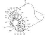
- FIG.It is a perspective view of special thread mill 1E. It is a perspective view of the insert 9. It is a perspective view of the insert part 3 which combined the inserts 4 and 9.
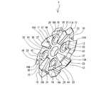
- the thread mill 1Ais a tool for cutting a female screw by milling with respect to the hole 6 provided in the workpiece 7 (see FIG. 22).
- the thread mill 1Ais an insert-type tool, and includes a substantially cylindrical body 2A and an insert portion 3 that is detachably fixed to a distal end portion (one axial end portion) of the body 2A.
- the body 2Ais a shank that is attached to a spindle or the like of a machine tool (not shown) and rotated.
- the material of the body 2Afor example, carbon steel, alloy steel, or the like, which has lower wear resistance, hardness, strength, and the like compared to inserts 4 and 5 described later that constitute the insert portion 3, can be employed.
- the insert portion 3is detachably fixed with four screws 8 to the distal end portion of the body 2A.
- the insert portion 3is configured by superimposing one or a plurality of disc-shaped inserts on the same axis.
- the insert portion 3 shown in FIG. 1is configured by overlapping two inserts 4 and 5 on the same axis.
- the inserts 4 and 5are made of a predetermined material such as cemented carbide, ceramic, or high-speed tool steel. Further, if necessary, a hard coating such as a compound coating such as TiN, TiCN, TiAlN, or CrN, a DLC (Diamond-Like Carbon) film, or a diamond coating may be coated. You may give it.
- the inserts 4 and 5can be used for different purposes, for example.
- the insert 4is for finishing and the insert 5 is for roughing.
- the insert portion 3includes the insert 4 on the front end side in the axial direction and the insert 5 on the rear end side in the axial direction.
- the thread mill 1A provided with such an insert portion 3is used as a tool for cutting a right screw with a right blade down cut with respect to a hole 6 provided in the workpiece 7 (see FIG. 22).
- This thread mill 1 ⁇ / b> Acan perform combined machining in which roughing and finishing are performed at the same time in one pass with a right blade downcut.
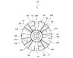
- the structure of the insert 4will be specifically described with reference to FIGS. 4 is a side view when the insert 4 shown in FIG. 3 is viewed from the direction of the arrow D1.
- the insert 4includes an insert main body 10 and eight blade portions 11 to 18. Since the insert 4 is for finishing, the diameter thereof is smaller than that of a roughing insert 5 described later.
- the insert main body 10is formed in a substantially disk shape having a predetermined thickness, and includes one surface 10A and another surface 10B (see FIG. 4).
- the insert body 10includes a shaft hole 41 and four insertion holes 43 to 46.
- the shaft hole 41is provided at the center of the insert body 10 and penetrates the one surface 10A and the other surface 10B.
- a boss 111see FIG.
- the four insertion holes 43 to 46are respectively arranged in the cross direction around the shaft hole 41, and are provided at positions corresponding to blade parts 12, 14, 16, and 18 to be described later. Four screws 8 (see FIG. 1) are inserted into these insertion holes 43 to 46.
- the blade portions 11 to 18are provided at equal intervals in the circumferential direction at the outer peripheral edge portion of the insert body 10. For convenience of explanation, it is assumed that the blade portions 11 to 18 are sequentially arranged clockwise when the insert body 10 is viewed from the one surface 10A.
- the blade portions 11 to 18are formed in a substantially triangular shape protruding outward in the radial direction when viewed from the circumferential direction.
- the blade edges 11A to 18A of the blade portions 11 to 18are respectively arranged on the left side in the circumferential direction when viewed from the one surface 10A side (the right side in the circumferential direction when viewed from the other surface 10B).
- the surface shape of the insert body 10will be described.
- eight substantially fan-shaped convex portions 21 to 28, eight substantially fan-shaped concave portions 31 to 38, and an annular concave portion 39are provided, respectively.
- the convex portions 21 to 28are provided at positions corresponding to the blade portions 11 to 18, respectively.
- the convex portion 21is provided between the blade portion 11 and the shaft hole 41 so as to protrude in the thickness direction of the insert main body 10, and is tapered from the base portion of the blade portion 11 toward the shaft hole 41 side.
- the convex portion 22is provided between the blade portion 12 and the insertion hole 43 so as to protrude in the thickness direction of the insert body 10 and is tapered from the base portion of the blade portion 12 toward the insertion hole 43 side.
- the convex portions 23, 25, 27are provided between the blade portions 13, 15, 17 and the shaft hole 41 so as to protrude in the thickness direction of the insert body 10, and the blade portions 13, 15, It is tapered from the base of 17 toward the shaft hole 41 side.
- the convex portions 24, 26, 28are provided between the insertion holes 44, 45, 46 and the blade portions 14, 16, 18 so as to protrude in the thickness direction of the insert body 10.
- the blade portions 14, 16, 18are tapered from the respective base portions toward the insertion holes 44, 45, 46 side.
- the concave portions 31 to 38are provided at portions other than the convex portions 21 to 28 and between the convex portions 21 to 28. In the thickness direction of the insert body 10, the concave portions 21 to 38 are provided. It is formed lower than 28.
- the concave portion 31is provided between the convex portions 21 and 22 and is tapered from the outer peripheral edge portion of the insert body 10 toward the shaft hole 41 side.
- the recessed part 32is provided between the convex parts 22 and 23, the recessed part 33 is provided between the convex parts 23 and 24, and the recessed part 34 is provided between the convex parts 24 and 25.
- the concave portion 35is provided between the convex portions 25 and 26, the concave portion 36 is provided between the convex portions 26 and 27, the concave portion 37 is provided between the convex portions 27 and 28, and the concave portion 38.
- the annular recess 39is formed annularly along the outer peripheral edge of the shaft hole 41 and lower than the projections 21 to 28, and is connected to the end of each of the recesses 31 to 38 on the shaft hole 41 side.
- the annular recess 39 and the recesses 31 to 38are flush with each other. As shown in FIG.
- the convex portions 21 to 28 and the concave portions 31 to 38 provided on the one surface 10A and the convex portions 21 to 28 and the concave portions 31 to 38 provided on the other surface 10Bare the thickness of the insert 10 main body. They are arranged at the same position in the direction.
- the length from the center in the thickness direction of the insert body 10 to the tip portions of the convex portions 21 to 28 on the one surface 10A sideis M1, and the convexity on the other surface 10B side
- the length from the center of the insert body 10 in the thickness direction to the bottom of each of the recesses 31 to 38 on the one surface 10A sideis N1
- the center in the thickness direction of the insert body 10is N2.
- the thickness L1 of the insert 4is the length from the convex portions 21 to 28 on the one surface 10A side to the convex portions 21 to 28 on the other surface 10B side, it is a length obtained by adding M1 and M2.
- FIG. 7is a side view when the insert 5 shown in FIG. 6 is viewed from the direction of the arrow D3.
- the insert 5includes an insert body 50 and eight blade portions 51 to 58.
- the insert body 50is formed in a substantially disk shape having a predetermined thickness, and includes one surface 50A and another surface 50B (see FIG. 7).
- the insert body 50includes a shaft hole 81 and four insertion holes 83 to 86.
- the shaft hole 81is provided at the center of the insert body 50 and penetrates the one surface 50A and the other surface 50B.
- a boss 111see FIG.
- the four insertion holes 83 to 86are arranged in the cross direction around the shaft hole 81, respectively, between the blade portions 51 and 52, between the blade portions 53 and 54, between the blade portions 55 and 56, and the blade portion 57. And 58 are provided at corresponding positions. Four screws 8 (see FIG. 1) are inserted into these insertion holes 83 to 86.
- the blade parts 51 to 58are provided at equal intervals in the circumferential direction at the outer peripheral edge part of the insert body 50. For convenience of explanation, it is assumed that the blade portions 51 to 58 are sequentially arranged clockwise when the insert body 50 is viewed from the one surface 50A.
- the blade portions 51 to 58are formed in a substantially triangular shape protruding outward in the radial direction when viewed from the circumferential direction.
- the blade edges 51A to 58A of the blade portions 51 to 58are respectively arranged on the left side in the circumferential direction when viewed from the one surface 50A side (the right side in the circumferential direction when viewed from the other surface 50B).
- the surface shape of the insert body 50will be described.
- eight substantially fan-shaped convex portions 61 to 68, eight substantially fan-shaped concave portions 71 to 78, and an annular concave portion 79are provided.
- the convex portions 61 to 68are provided at positions corresponding to the blade portions 51 to 58, respectively.
- the convex portion 61is provided between the blade portion 51 and the shaft hole 81 so as to protrude in the thickness direction of the insert body 50 and is tapered from the base portion of the blade portion 51 toward the shaft hole 81 side.
- a portion overlapping the insertion hole 83 of the convex portion 61is formed to be curved along the outer edge portion of the insertion hole 83 that is curved.
- the convex portion 62is provided between the blade portion 52 and the shaft hole 81 so as to protrude in the thickness direction of the insert body 50 and is tapered from the base portion of the blade portion 52 toward the shaft hole 81 side.
- a portion overlapping the insertion hole 83 of the convex portion 62is formed by being curved along the outer edge portion where the insertion hole 83 is curved.
- the convex portions 63 and 64are provided between the blade portions 53 and 54 and the shaft hole 81 so as to protrude in the thickness direction of the insert body 50, and the base portions of the blade portions 53 and 54. It is formed to taper from the shaft hole 81 toward the shaft hole 81. Portions overlapping the insertion holes 84 of the convex portions 63 and 64 are formed to be curved along the outer edge portions of the insertion holes 84 that are curved.
- the convex portions 65 and 66are provided between the blade portions 55 and 56 and the shaft hole 81 so as to protrude in the thickness direction of the insert body 50 and are tapered from the base portion of the blade portions 55 and 56 toward the shaft hole 81 side. Has been.
- the portions overlapping the insertion holes 85 of the convex portions 65 and 66are formed to be curved along outer curved edge portions of the insertion holes 85.
- the convex portions 67 and 68are provided between the blade portions 57 and 58 and the shaft hole 81 so as to protrude in the thickness direction of the insert body 50, and are tapered from the base portion of the blade portions 57 and 58 toward the shaft hole 81. ing.
- Portions overlapping the insertion holes 86 of the convex portions 67 and 68are formed to be curved along outer curved edge portions of the insertion holes 86.
- the recesses 71 to 78are provided between the protrusions 61 to 68 except for the protrusions 61 to 68, and in the thickness direction of the insert body 50, the protrusions 61 to 68 are provided. It is formed lower than 68.
- the concave portion 71is provided between the convex portions 61 and 62
- the concave portion 72is provided between the convex portions 62 and 63
- the concave portion 73is provided between the convex portions 63 and 64
- the concave portion 74is convex.
- the concave portion 75is provided between the convex portions 65 and 66, the concave portion 76 is provided between the convex portions 66 and 67, and the concave portion 77 is provided between the convex portions 67 and 68.
- the concave portion 78is provided between the convex portions 68 and 61.
- the recesses 71 to 78are each tapered from the outer peripheral edge of the insert body 50 toward the shaft hole 81 side.
- the insertion holes 83 to 86are provided on the shaft hole 81 side of the recesses 71, 73, 75, 77.
- the annular recess 79is formed annularly along the outer peripheral edge of the shaft hole 81 and lower than the projections 61 to 68, and is connected to the end of each of the recesses 71 to 78 on the shaft hole 81 side.
- the annular recess 79 and the recesses 71 to 78are flush with each other. As shown in FIG.
- the convex portions 61 to 68 and the concave portions 71 to 78 provided on the one surface 50A, and the convex portions 61 to 68 and the concave portions 71 to 78 provided on the other surface 50Bare the thickness of the insert main body 50. They are arranged at the same position in the direction.
- the length from the center in the thickness direction of the insert body 50 to the respective distal end portions of the convex portions 61 to 68 on the one surface 50A sideis M3, and the respective distal ends of the convex portions 61 to 68 on the other surface 50B side
- the length from the center in the thickness direction of the insert body 50 to the bottom of each of the recesses 71 to 78 on the one surface 50A sideis N3, the recess from the center in the thickness direction of the insert body 50 to the other surface 50B side.
- the length to the bottom of each of 71 to 78is N4.
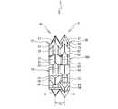
- the insert 4 shown in FIG. 8shows a side surface when the insert 4 of FIG. 3 is viewed from the direction of the arrow D2.
- the insert 5 shown in FIG. 8shows a side surface when the insert 5 of FIG. 6 is viewed from the direction of the arrow D4.
- the insert 5is indicated by a solid line
- the insert 4is indicated by a two-dot chain line.
- the other surface 10B of the insert 4 and the one surface 50A of the insert 5are opposed to each other and overlap each other. At this time, the other surface 10B and the one surface 50A become the mating surfaces.
- the convex portion 21 provided on the other surface 10Bis inserted into the concave portion 78 provided on the one surface 50A.
- the convex portion 22 provided on the other surface 10Bis inserted into the concave portion 71 provided on the one surface 50A.
- the convex portion 23 provided on the other surface 10Bis inserted into the concave portion 72 provided on the one surface 50A.
- the convex portion 24 provided on the other surface 10Bis inserted into the concave portion 73 provided on the one surface 50A.
- the convex portion 25 provided on the other surface 10Bis inserted into the concave portion 74 provided on the one surface 50A.
- the convex portion 26 provided on the other surface 10Bis inserted into the concave portion 75 provided on the one surface 50A.
- the convex portion 27 provided on the other surface 10Bis inserted into the concave portion 76 provided on the one surface 50A.
- the convex portion 28 provided on the other surface 10Bis inserted into the concave portion 77 provided on the one surface 50A.
- the convex portion 61 provided on the one surface 50Ais inserted into the concave portion 31 provided on the other surface 10B.
- the convex portion 62 provided on the one surface 50Ais inserted into the concave portion 32 provided on the other surface 10B.
- the convex portion 63 provided on the one surface 50Ais inserted into the concave portion 33 provided on the other surface 10B.
- the convex portion 64 provided on the one surface 50Ais inserted into the concave portion 34 provided on the other surface 10B.
- the convex portion 65 provided on the one surface 50Ais inserted into the concave portion 35 provided on the other surface 10B.
- the convex portion 66 provided on the one surface 50Ais inserted into the concave portion 36 provided on the other surface 10B.
- the convex portion 67 provided on the one surface 50Ais inserted into the concave portion 37 provided on the other surface 10B.
- the convex portion 68 provided on the one surface 50Ais inserted into the concave portion 38 provided on the other surface 10B. In this way, the inserts 4 and 5 are coaxially overlapped with each other to form the insert portion 3.
- the tip portion of the convex portion 21 provided on the other surface 10Bcomes into contact with the bottom portion of the concave portion 78 provided on the one surface 50A.
- the tip of the convex portion 22 provided on the other surface 10Bcomes into contact with the bottom of the concave portion 71 provided on the one surface 50A.
- the tip of the convex portion 23 provided on the other surface 10Bcomes into contact with the bottom of the concave portion 72 provided on the one surface 50A.
- the tip of the convex portion 24 provided on the other surface 10Bcomes into contact with the bottom of the concave portion 73 provided on the one surface 50A.
- the tip of the convex portion 25 provided on the other surface 10Bcomes into contact with the bottom of the concave portion 74 provided on the one surface 50A.
- the tip of the convex portion 26 provided on the other surface 10Bcomes into contact with the bottom of the concave portion 75 provided on the one surface 50A.
- the tip of the convex portion 27 provided on the other surface 10Bcomes into contact with the bottom of the concave portion 76 provided on the one surface 50A.
- the tip of the convex portion 28 provided on the other surface 10Bcomes into contact with the bottom of the concave portion 77 provided on the one surface 50A.
- the tip of the convex portion 61 provided on the other surface 50Bfaces the bottom of the concave portion 31 provided on the one surface 50A with a gap.
- the tip of the convex portion 62 provided on the other surface 50Bis opposed to the bottom of the concave portion 32 provided on the one surface 50A with a gap, and the tip of the convex portion 63 provided on the other surface 50B is It faces the bottom of the recess 33 provided on the one surface 50A with a gap.
- the tip of the convex portion 64 provided on the other surface 50Bis opposed to the bottom of the concave portion 34 provided on the one surface 50A with a gap.
- the tip of the convex portion 65 provided on the other surface 50Bfaces the bottom of the concave portion 35 provided on the one surface 50A with a gap.
- the tip of the protrusion 66 provided on the other surface 50Bfaces the bottom of the recess 36 provided on the one surface 50A with a gap.
- the tip of the protrusion 67 provided on the other surface 50Bfaces the bottom of the recess 37 provided on the one surface 50A with a gap.
- the tip of the convex portion 68 provided on the other surface 50Bfaces the bottom of the concave portion 38 provided on the one surface 50A with a gap.
- the thickness L3 of the insert portion 3is such that the tip portions of the convex portions 21 to 28 provided on the one surface 10A of the insert 4 and the convex portions 61 to 68 provided on the other surface 50B of the insert 5 are provided. It corresponds to the distance between each tip. Then, as described above, the convex portions and the concave portions of the other surface 10B and the one surface 50A are overlapped with each other, whereby the thickness M2 on the other surface 10B side of the insert 4 and the thickness M3 on the one surface 50A side of the insert 5 are overlapped. Can be overlapped with each other in the thickness direction of the insert portion 3.
- the thread mill 1Acan make the thickness L3 of the insert portion 3 shorter than the distance obtained by adding the thickness L1 of the insert 4 (see FIG. 4) and the thickness L2 of the insert 5 (see FIG. 7).
- the thickness of the insert 4is 5 mm and the thickness of the insert 5 is 4 mm
- the total thickness of the single pieces of the inserts 4 and 5is 9 mm
- the total thickness in the stacked stateis 8 mm.
- the length in which the inserts 4 and 5 overlap each other in the thickness directionis 1 mm.
- the tip portions of the convex portions 21 to 28 on the other surface 10B of the insert 4come into contact with the bottoms of the concave portions 71 to 78 on the one surface 50A of the insert 5, respectively.
- the tip of 68does not contact the bottom of the recesses 31 to 38 of the insert 4. This is because the height of the convex portions 61 to 68 of the insert 5 is lower than the depth of the concave portions 31 to 38 of the insert 4.
- the height of the convex portionis a difference in height from the concave portion, and is the length from the bottom of the concave portion to the tip portion of the convex portion.
- the depth of the concave portionis a height difference from the convex portion, and is a length from the tip portion of the convex portion to the bottom portion of the concave portion.
- FIG. 10 and FIG. 11the arrangement conditions of the convex portion and the concave portion in the insert will be described.
- the convex portions and the concave portions provided on the mating surfaces of the inserts 4 and 5 shown in FIG. 8can be overlapped with each other even if one or both of the inserts 4 and 5 are turned over.
- the arrangement conditions of the convex part and the concave partwill be described by taking the insert 130 shown in FIGS.
- FIG. 10is a side view of the insert 130 of FIG. 11 when viewed from the direction of the arrow D5.
- the insert 130includes a disc-shaped insert main body 140. 10 and 11, the blade portion, shaft hole, and insertion hole provided in the insert 130 are omitted.
- the insert main body 140includes one surface 140A and the other surface 140B. The surface shape of the one surface 140A and the other surface 140B is the same.
- the minimum angle of the two virtual straight lines that respectively contact the outermost peripheral edge portion of the convex portion 142is X2
- the two virtual straight lines that respectively contact the outermost peripheral edge portion of the convex portion 143are The minimum angle is X3
- the minimum angle of the two virtual straight lines that are in contact with the outermost peripheral edge of the convex portion 144is X4
- the minimum angle of the two virtual straight lines that are in contact with the outermost peripheral edge of the convex portion 145is X5.
- Each shape of the convex portions 141 to 145may be any shape as long as it is between two virtual straight lines.
- the two virtual straight lines B1 and B2 that are in contact with the outermost peripheral edge portions on both sides in the circumferential direction of the concave portion 151 from the center Oare drawn, and the maximum angle when the convex portion is not included between the virtual straight lines B1 and B2 is determined.
- the maximum angle when the convex portion is not included between the two virtual straight lines that respectively contact the outermost peripheral edge portion of the concave portion 152is Y2, and the two that contact the outermost peripheral edge portion of the concave portion 153 respectively.
- Y3is the maximum angle when no convex portion is included between the virtual straight lines
- Y4is the maximum angle when the convex portion is not included between the two virtual straight lines contacting the outermost peripheral edge of the concave portion 154, respectively.
- the maximum angle when no convex portion is included between two virtual straight lines that respectively contact the outermost peripheral edge portion of 155is Y5.
- Any of X1 to X5is smaller than Y1 to Y5 (2)
- the sum of X1 to X5 of each of the convex portions 141 to 145is less than 180 ° (3)
- the sum of Y1 to Y5 of each of the concave portions 151 to 155is More than 180 ° (4)
- the maximum angle X max out of X1 to X5is less than 180/5 ° (5)
- the maximum angle Y max out of Y1 to Y5is larger than 180/5 °
- the shape of the mounting surface 90 of the body 2Awill be described with reference to FIGS.
- the body 2Aincludes a circular mounting surface 90 at the tip.
- the insert 5(see FIGS. 5 and 6) can be detachably attached to the attachment surface 90.
- the mounting surface 90is provided with a boss 111 and four screw holes 113 to 116, respectively.
- the boss 111is provided at the center of the mounting surface 90 and is formed in a substantially cylindrical shape extending along the axis of the body 2A.
- the four screw holes 113 to 116are respectively arranged in a cross direction around the boss 111, and are sequentially arranged clockwise.
- Four screws 8(see FIG. 1) are fastened to these screw holes 113 to 116.
- the mounting surface 90has an uneven shape corresponding to the uneven shape on both sides of the insert 5.
- the mounting surface 90is provided with eight substantially fan-shaped convex portions 91 to 98, eight substantially fan-shaped concave portions 101 to 108, and an annular concave portion 109, respectively.
- the convex portion 91is provided in the center between the screw holes 113 and 116 so as to protrude in parallel to the axial direction of the body 2A, and is tapered from the outer peripheral edge portion of the mounting surface 90 toward the boss 111 side.
- the projecting portion 92is provided between the screw hole 113 and the outer peripheral edge portion so as to protrude in parallel to the axial direction of the body 2 ⁇ / b> A, and is tapered from the outer peripheral edge portion toward the screw hole 113.
- the convex portion 93is at the center between the screw holes 113 and 114, the convex portion 95 is at the center between the screw holes 114 and 115, and the convex portion 97 is between the screw holes 115 and 116.
- the convex portion 94is between the screw hole 114 and the outer peripheral edge portion, the convex portion 96 is between the screw hole 115 and the outer peripheral edge portion, and the convex portion 98 is outside the screw hole 116 and the outer peripheral edge portion. It is provided between the peripheral edge so as to protrude parallel to the axial direction of the body 2A, and is tapered from the outer peripheral edge of the mounting surface 90 toward the screw holes 114, 115, and 116, respectively.
- the concave portions 101 to 108are provided between the convex portions 91 to 98, and are formed lower on the rear end side in the axial direction than the convex portions 91 to 98 in the axial direction of the body 2A.
- the concave portion 101is provided between the convex portions 91 and 92 and is tapered from the outer peripheral edge portion of the mounting surface 90 toward the boss 111 side.
- the concave portion 102is provided between the convex portions 92 and 93
- the concave portion 103is provided between the convex portions 93 and 94
- the concave portion 104is provided between the convex portions 94 and 95.
- the concave portion 105is provided between the convex portions 95 and 96, the concave portion 106 is provided between the convex portions 96 and 97, the concave portion 107 is provided between the convex portions 97 and 98, and the concave portion 108.
- the annular recess 109is provided annularly along the outer periphery of the boss 111 and is connected to the end of each of the recesses 101 to 108 on the boss 111 side.
- the annular recess 109is formed lower than the recesses 101 to 108 in the axial direction of the body 2A.
- the convex portions 91 to 98 and the concave portions 101 to 108 of the mounting surface 90also satisfy the above-described arrangement conditions of the convex portions and the concave portions.
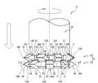
- a method for attaching the insert portion 3 to the body 2Awill be described with reference to FIGS.
- a method of attaching the insert portion 3 to the body 2Awill be described for the purpose of creating the thread mill 1A shown in FIG.
- the insert 2can be attached to the body 2A. Therefore, the other surface 50B side of the insert 5 in the insert portion 3 is opposed to the mounting surface 90 of the body 2A.
- the boss 111 of the mounting surface 90is inserted in the order of the shaft hole 81 of the insert 5 and the shaft hole 41 of the insert 4.
- the other surface 50 ⁇ / b> B of the insert 5is overlapped with the mounting surface 90. At this time, the other surface 50B and the mounting surface 90 become a mating surface.
- the mounting surface 90 of the body 2Ais indicated by a solid line
- the insert 5is indicated by a two-dot chain line.
- the convex portion 61 provided on the other surface 50 ⁇ / b> B of the insert 5is inserted into the concave portion 101 provided on the mounting surface 90.
- the convex portion 62 provided on the other surface 50 ⁇ / b> Bis inserted into the concave portion 102 provided on the attachment surface 90.
- the convex portion 63 provided on the other surface 50Bis inserted into the concave portion 103 provided on the mounting surface 90.
- the convex portion 64 provided on the other surface 50 ⁇ / b> Bis inserted into the concave portion 104 provided on the attachment surface 90.
- the convex portion 65 provided on the other surface 50Bis inserted into the concave portion 105 provided on the mounting surface 90.
- the convex portion 66 provided on the other surface 50Bis inserted into the concave portion 106 provided on the mounting surface 90.
- the convex portion 67 provided on the other surface 50 ⁇ / b> Bis inserted into the concave portion 107 provided on the attachment surface 90.
- the convex portion 68 provided on the other surface 50 ⁇ / b> Bis inserted into the concave portion 108 provided on the attachment surface 90.
- the convex portion 91 provided on the mounting surface 90is inserted into the concave portion 78 provided on the other surface 50B.
- the convex portion 92 provided on the attachment surface 90is inserted into the concave portion 71 provided on the other surface 50B.
- the convex portion 93 provided on the attachment surface 90is inserted into the concave portion 72 provided on the other surface 50B.
- the convex portion 94 provided on the attachment surface 90is inserted into the concave portion 73 provided on the other surface 50B.
- the convex portion 95 provided on the attachment surface 90is inserted into the concave portion 74 provided on the other surface 50B.
- the convex portion 96 provided on the attachment surface 90is inserted into the concave portion 75 provided on the other surface 50B.
- the convex portion 97 provided on the attachment surface 90is inserted into the concave portion 76 provided on the other surface 50B.
- the convex portion 98 provided on the attachment surface 90is inserted into the concave portion 77 provided on the other surface 50B.
- the tip of the convex portion 91 provided on the attachment surface 90is the other surface. It contacts the bottom of the recess 78 provided in 50B.
- the tip of the convex portion 92 provided on the mounting surface 90comes into contact with the bottom of the concave portion 71 provided on the other surface 50B.
- the tip of the convex portion 93 provided on the mounting surface 90comes into contact with the bottom of the concave portion 72 provided on the other surface 50B.
- the tip of the convex portion 94 provided on the mounting surface 90comes into contact with the bottom of the concave portion 73 provided on the other surface 50B.
- the tip of the convex portion 95 provided on the attachment surface 90comes into contact with the bottom of the concave portion 74 provided on the other surface 50B.
- the tip of the convex portion 96 provided on the mounting surface 90comes into contact with the bottom of the concave portion 75 provided on the other surface 50B.
- the tip of the convex portion 97 provided on the mounting surface 90comes into contact with the bottom of the concave portion 76 provided on the other surface 50B.
- the tip of the convex portion 98 provided on the attachment surface 90comes into contact with the bottom of the concave portion 77 provided on the other surface 50B.
- the tip of the convex portion 61 provided on the other surface 50Bfaces the bottom of the concave portion 101 provided on the mounting surface 90 with a gap.
- the front end portion of the convex portion 62 provided on the other surface 50Bfaces the bottom portion of the concave portion 102 provided on the mounting surface 90 with a gap.
- the tip of the convex portion 63 provided on the other surface 50Bfaces the bottom of the concave portion 103 provided on the mounting surface 90 with a gap.
- the tip of the convex portion 64 provided on the other surface 50Bfaces the bottom of the concave portion 104 provided on the mounting surface 90 with a gap.
- the tip of the convex portion 65 provided on the other surface 50Bfaces the bottom of the concave portion 105 provided on the mounting surface 90 with a gap.
- the tip of the convex portion 66 provided on the other surface 50Bfaces the bottom of the concave portion 106 provided on the mounting surface 90 with a gap.
- the tip of the convex portion 67 provided on the other surface 50 ⁇ / b> Bfaces the bottom of the concave portion 107 provided on the mounting surface 90 with a gap.
- the tip of the convex portion 68 provided on the other surface 50Bfaces the bottom of the concave portion 108 provided on the mounting surface 90 with a gap.
- the convex portions and the concave portions of the attachment surface 90 and the other surface 50Bare overlapped with each other, so that the front end portion of the body 2A and the thickness M4 on the other surface 50B side of the insert 5 are reduced. They can overlap each other in the axial direction. Thereby, the thread mill 1A can further shorten the protruding length of the insert portion 3 in the axial direction.
- the convex portions 91 to 98 on the mounting surface 90 sideabut on the concave portions 71 to 78 on the insert 5 side, respectively, but the convex portions 61 to 68 on the insert 5 side are concave portions on the mounting surface 90 side. No contact with 101-108. Thereby, since the insert 5 can be piled up parallel to the mounting surface 90 without deviation, the insert portion 3 can be mounted orthogonally to the body 2A.
- the shape of the mounting surface 190 of the body 2Bwill be described with reference to FIGS.
- the body 2Bincludes a circular attachment surface 190 at the tip.
- the insert 4(see FIGS. 2 and 3) can be attached to the attachment surface 190.
- the mounting surface 190is provided with a boss 211 and four screw holes 213 to 216, respectively.
- the boss 211is provided at the center of the mounting surface 190 and is formed in a substantially columnar shape extending along the axis of the body 2B.
- the four screw holes 213 to 216are arranged in a cross direction around the boss 211, and are arranged in order clockwise.
- Four screws 8(see FIG. 1) are fastened to these screw holes 213 to 216.
- the mounting surface 190has an uneven shape corresponding to the uneven shape on both sides of the insert 4.
- the mounting surface 190is provided with eight substantially fan-shaped convex portions 191 to 198, eight substantially fan-shaped concave portions 201 to 208, and an annular concave portion 209, respectively.
- the convex portions 191 and 192are provided so as to sandwich the screw hole 213 from both sides in the circumferential direction.
- the convex portions 193 and 194are provided so as to sandwich the screw hole 214 from both sides in the circumferential direction.
- the convex portions 195 and 196are provided so as to sandwich the screw hole 215 from both sides in the circumferential direction.
- the convex portions 197 and 198are provided so as to sandwich the screw hole 216 from both sides in the circumferential direction. These convex portions 191 to 198 are provided so as to protrude in parallel to the axial direction of the body 2A, and are respectively tapered from the outer peripheral edge portion of the mounting surface 190 toward the boss 111 side.
- the concave portions 201 to 208are provided between the convex portions 191 to 198, and are formed lower in the axial direction rear end side than the convex portions 191 to 198 in the axial direction of the body 2B.
- the concave portion 201is provided between the convex portions 191 and 192
- the concave portion 202is provided between the convex portions 192 and 193
- the concave portion 203is provided between the convex portions 193 and 194
- the concave portion 204is convex.
- the concave portion 205is provided between the convex portions 195 and 196, the concave portion 206 is provided between the convex portions 196 and 197, and the concave portion 207 is provided between the convex portions 197 and 198.
- the recess 208is provided between the protrusions 198 and 191 and is tapered from the outer peripheral edge of the mounting surface 190 toward the boss 211.
- the screw hole 213is provided on the boss 211 side of the recess 201, the screw hole 214 is provided on the boss 211 side of the recess 203, the screw hole 215 is provided on the boss 211 side of the recess 205, and the screw hole 216 is It is provided on the boss 211 side of the recess 207.
- the annular recess 209is annularly provided along the outer periphery of the boss 211 and is connected to the end of each of the recesses 201 to 208 on the boss 211 side.
- the annular recess 209is formed lower on the rear end side in the axial direction than the recesses 201 to 208 in the axial direction of the body 2B.
- the convex portions 191 to 198 and the concave portions 201 to 208 of the mounting surface 190also satisfy the above-described arrangement conditions of the convex portions and the concave portions.
- FIGS. 17 and 19a method of attaching the insert portion 3 to the body 2B will be described.
- a method of attaching the insert portion 3 to the body 2Bwill be described for the purpose of creating the thread mill 1B shown in FIG.
- the insert 2can be attached to the body 2B. Therefore, the other surface 10B side of the insert 4 in the insert portion 3 is opposed to the mounting surface 190 of the body 2B.
- the boss 211 of the mounting surface 190is inserted in the order of the shaft hole 41 of the insert 4 and the shaft hole 81 of the insert 5.
- the other surface 10 ⁇ / b> B of the insert 4is overlapped with the mounting surface 190. At this time, the other surface 10B and the mounting surface 190 become a mating surface.
- the mounting surface 190 of the body 2Bis indicated by a solid line
- the insert 4is indicated by a two-dot chain line.
- the convex portion 21 provided on the other surface 10B of the insert 4is inserted into the concave portion 208 provided on the mounting surface 190.
- the convex portion 22 provided on the other surface 10Bis inserted into the concave portion 201 provided on the mounting surface 190.
- the convex portion 23 provided on the other surface 10Bis inserted into the concave portion 202 provided on the mounting surface 190.
- the convex portion 24 provided on the other surface 10Bis inserted into the concave portion 203 provided on the mounting surface 190.
- the convex portion 25 provided on the other surface 10Bis inserted into the concave portion 204 provided on the mounting surface 190.
- the convex portion 26 provided on the other surface 10Bis inserted into the concave portion 205 provided on the mounting surface 190.
- the convex portion 27 provided on the other surface 10Bis inserted into the concave portion 206 provided on the attachment surface 190.
- the convex portion 28 provided on the other surface 10Bis inserted into the concave portion 207 provided on the mounting surface 190.
- the convex portion 191 provided on the mounting surface 190is inserted into the concave portion 31 provided on the other surface 10B of the insert 4.
- the convex portion 192 provided on the attachment surface 190is inserted into the concave portion 32 provided on the other surface 10B.
- the convex portion 193 provided on the attachment surface 190is inserted into the concave portion 33 provided on the other surface 10B.
- the convex portion 194 provided on the mounting surface 190is inserted into the concave portion 34 provided on the other surface 10B.
- the convex portion 195 provided on the attachment surface 190is inserted into the concave portion 35 provided on the other surface 10B.
- the convex portion 196 provided on the attachment surface 190is inserted into the concave portion 36 provided on the other surface 10B.
- the convex portion 197 provided on the attachment surface 190is inserted into the concave portion 37 provided on the other surface 10B.
- the convex portion 198 provided on the attachment surface 190is inserted into the concave portion 38 provided on the other surface 10B.
- the convex portions and the concave portions of the mounting surface 190 and the other surface 10Bare overlapped with each other, so that the tip end portion of the body 2B and the thickness M1 on the other surface 10B side of the insert 4 are changed in the axial direction of the thread mill 1B. Can be stacked on each other. Thereby, the thread mill 1B can further shorten the protruding length of the insert portion 3 in the axial direction.
- the tips of the projections 191 to 198 on the mounting surface 190are brought into contact with the bottoms of the recesses 31 to 38 on the insert 4 side, respectively, and the tips of the projections 21 to 28 on the insert 4 side are contacted. May not be brought into contact with the bottoms of the recesses 201 to 208 on the mounting surface 190 side.
- the insert portion 3can be mounted orthogonally to the body 2B.
- the thread mill of the present embodimenthas four types of internal threads that are cut into the hole 6 (see FIG. 22) provided in the workpiece 7 by changing the order and direction in which the inserts 4 and 5 constituting the insert portion 3 are overlapped.
- a cutting methodcan be realized.
- a thread mill 1A shown in FIG. 18is a thread mill for cutting down a right blade.
- a thread mill 1B shown in FIG. 19is a thread mill for upcutting a right blade.
- a thread mill 1C shown in FIG. 20is a thread mill for cutting down the left blade.
- a thread mill 1D shown in FIG. 21is a thread mill for left blade upcut.
- the female thread to be cut into the hole 6is a right-hand thread.
- the thread mill 1Aincludes an insert portion 3 and a body 2A.
- the cutting edges 11A to 18A of the insert 4 and the cutting edges 51A to 58A of the insert 5are both aligned so as to be the right blade (on the left side of the cutting portion in FIG. 18). 5 are placed on top of each other so that they are on the upper side.
- the other surface 50B (refer FIG. 8) of the insert 5 located above the insert part 3is attached to the attachment surface 90 of the body 2A.
- the cutting processincludes a first process, a second process, and a third process.
- the cutting processis performed by a machine tool (not shown), and the direction parallel to the axial direction of the thread mill attached to the main shaft of the machine tool is defined as the Z-axis direction.
- the main shaftis lowered in the Z-axis direction, and the insert portion 3 of the thread mill 1A is inserted to the machining depth of the screw formed in the hole 6 previously formed in the workpiece 7. Then, the thread mill 1A is rotated clockwise as viewed from the axial rear end side.
- the main shaftis spirally raised while rotating counterclockwise along the inner peripheral surface of the hole 6. At this time, the thread mill 1A is raised in the Z-axis direction by a predetermined height by one rotation.
- the third stepis finished by cutting to the mouth of the screw. As a result, a right-hand thread is formed on the inner peripheral surface of the hole 6.
- the advantage of the right blade downcutis, for example, that it is not affected by the chip volume and is effective for the tool life. Since the insert 5 is for roughing and the insert 4 is for finishing, the thread mill 1A can perform roughing and finishing simultaneously in one pass with a right blade downcut. Therefore, the operator can perform the cutting operation of the female screw in a short time by using the thread mill 1A.
- the thread mill 1Bincludes an insert portion 3 and a body 2B.
- the blade edges 11A to 18A of the insert 4 and the blade edges 51A to 58A of the insert 5are aligned so as to be both right blades, and the insert 4 is overlaid so that the insert 4 is on the upper side and the insert 5 is on the lower side. ing.
- one surface 10A of the insert 4 and the other surface 50B of the insert 5are mating surfaces.
- the other surface 10B of the insert 4 located above the insert part 3is attached to the attachment surface 190 of the body 2B.
- the cutting processincludes a first process, a second process, and a third process, and the procedure is reversed from that of the right blade downcut.
- the main shaftis lowered in the Z-axis direction, and the insert portion 3 of the thread mill 1 ⁇ / b> B is positioned at a portion that becomes the mouth of the female screw formed in the hole 6.
- the thread mill 1Bis rotated clockwise as viewed from the rear end side in the axial direction.
- the main shaftis lowered spirally while rotating clockwise along the inner peripheral surface of the hole 6.
- the thread mill 1Bis lowered in the Z-axis direction by a predetermined height by one rotation.
- the third stepis finished by cutting to the processing depth of the screw.
- a right-hand threadis formed on the inner peripheral surface of the hole 6.
- the advantage of the right blade upcutis that it is less susceptible to chips during cutting and the finished surface is improved.
- the thread mill 1Acan perform roughing and finishing simultaneously in one pass of the right blade upcut. Therefore, the operator can perform the cutting operation of the female screw in a short time by using the thread mill 1B.
- the thread mill 1Cincludes an insert portion 3 and a body 2B.
- the cutting edges 11A to 18A of the insert 4 and the cutting edges 51A to 58A of the insert 5are both aligned so as to be the left blade (on the right side of the cutting part in FIG. 20). It is piled up so that it may become the lower side.
- the other surface 10B of the insert 4 and the one surface 50A of the insert 5are mating surfaces. Then, one surface 10A of the insert 4 located on the upper side of the insert portion 3 is attached to the attachment surface 190 of the body 2B.
- the cutting stepincludes a first step, a second step, and a third step, similar to the right blade upcut shown in FIG.
- the main shaftis lowered in the Z-axis direction, and the insert portion 3 of the thread mill 1 ⁇ / b> C is positioned at a portion that becomes the mouth of the female screw formed in the hole 6.
- the thread mill 1Cis rotated counterclockwise as viewed from the axial rear end side.
- the direction of rotation of the tool shown in FIG. 23is opposite.
- the main shaftis lowered spirally while rotating clockwise along the inner peripheral surface of the hole 6.
- the third stepis finished by cutting to the mouth of the screw.
- a right-hand threadis formed in the hole 6.
- the advantage of the left blade downcutis, for example, that it is less susceptible to chips during cutting and is effective in tool life.
- the thread mill 1Ccan perform composite processing that simultaneously performs roughing and finishing with one pass of the left blade downcut.
- the configuration of the thread mill 1Dwill be described with reference to FIG.
- the thread mill 1Dincludes an insert portion 3 and a body 2A.
- the thread mill 1Dis aligned so that the blade edges 11A to 18A of the insert 4 and the blade edges 51A to 58A of the insert 5 are both left blades (on the right side of the blade portion in FIG. 21). Are stacked so that is on the upper side.
- the other surface 50B of the insert 5 and the one surface 10A of the insert 4are mating surfaces.
- one surface 50A of the insert 5 located above the insert part 3is attached to the attachment surface 90 of the body 2A.
- the cutting processincludes a first process, a second process, and a third process, similarly to the right blade downcut shown in FIG.
- the main shaftis lowered in the Z-axis direction, and the insert portion 3 of the thread mill 1D is inserted to the machining depth of the screw formed in the hole 6 previously formed in the workpiece 7.
- the thread mill 1Dis rotated counterclockwise as viewed from the rear end side in the axial direction.
- the direction of rotation of the tool shown in FIG. 22is opposite.
- the main shaftis spirally raised while rotating counterclockwise along the inner peripheral surface of the hole 6.
- the third stepis finished by cutting to the mouth of the screw. As a result, a right-hand thread is cut on the inner peripheral surface of the hole 6.
- the advantage of the left blade upcutis that the finished surface is improved without being affected by the volume of the chips.
- the thread mill 1Dcan perform roughing and finishing simultaneously in one pass of the left blade upcut. Therefore, the operator can perform the cutting operation of the female screw in a short time by using the thread mill 1D.
- the thread mill according to the present embodimentperforms four types of cutting on the female screw formed in the hole 6 provided in the workpiece 7 by changing the order and direction in which the inserts 4 and 5 constituting the insert portion 3 are overlapped. The method can be realized.
- the pitch adjusting method in the insert portion 3will be described.
- the pitch P 1 in the insert portion 3is the distance between the blade portions 11 to 18 of the insert 4 and the blade portions 51 to 58 of the insert 5.
- the pitch of the insert part 3there are, for example, the following three methods.
- the first pitch adjusting methodis a method of stacking inserts having different thicknesses. As shown in FIG. 24, for example, in the insert portion 3, the insert 40 thicker than the insert 4 shown in FIG. In this case, the pitch P2 of the insert portion 3 is a distance between the blade portions 11 to 18 of the insert 40 and the blade portions 51 to 58 of the insert 5. The pitch P2 is longer than the pitch P1. In addition, what is necessary is just to pile an insert thinner than the insert 4 when shortening a pitch. Further, the insert 5 may be replaced with an insert having a different thickness. Therefore, the pitch of the insert part 3 can be easily changed by the first pitch adjusting method.
- the second pitch adjusting methodis a method in which the spacer 300 is overlapped between the inserts 4 and 5.
- the spacer 300includes an annular portion 301 and four blade portions 311 to 314.
- the annular portion 301is formed in an annular shape having a shaft hole 310 at the center.
- the four blade portions 311 to 314are arranged in the annular portion 301 at equal intervals, and are each formed in a substantially fan shape whose width increases from the radially inner side toward the outer side.
- the shape of the blade portions 311 to 314corresponds to the concave shape of the insert 5.
- the spacer 300is indicated by a solid line
- the insert 5is indicated by a two-dot chain line.
- the spacer 300is disposed on one surface 50 ⁇ / b> A that is a mating surface of the insert 5.
- the annular portion 301 of the spacer 300is disposed in the annular recessed portion 79 of the other surface 50B
- the blade portion 311is disposed in the recessed portion 78 of the other surface 50B
- the blade portion 312is disposed in the recessed portion 72 of the other surface 50B.
- the part 313is arranged in the concave part 74 of the other surface 50B
- the blade part 314is arranged in the concave part 76 of the other surface 50B.
- the other surface 10B(see FIGS. 8 and 9) of the insert 4 is overlaid on the one surface 50A of the insert 5 on which the spacer 300 is disposed.
- the tip of the convex portion 21 of the insert 4comes into contact with the bottom of the concave portion 78 of the insert 5 via the blade portion 311 of the spacer 300.
- the tip of the convex portion 23 of the insert 4abuts the bottom of the concave portion 72 of the insert 5 via the blade portion 312 of the spacer 300.
- the tip of the convex portion 25 of the insert 4abuts the bottom of the concave portion 74 of the insert 5 via the blade portion 313 of the spacer 300.
- the tip of the convex portion 27 of the insert 4abuts against the bottom of the concave portion 76 of the insert 5 via the blade portion 314 of the spacer 300.
- the thickness of the insert 4is 5 mm
- the thickness of the insert 5is 4 mm
- the thickness of the spacer 300is 0.5 mm
- the total thickness of the single pieces of the inserts 4 and 5is 9.5 mm
- the thickness in a stacked stateIs a total of 8.5 mm.
- the length in which the inserts 4 and 5 overlap each other in the thickness directionis 1 mm.
- the pitch P3 of the insert portion 3is a distance obtained by adding the thickness of the spacer 300 to the pitch P1.
- the pitch P3is longer than the pitch P1.
- a spacer thicker than the spacer 300may be stacked, or a plurality of spacers 300 may be stacked.
- the pitch of the insert portion 3can be easily changed also by the second pitch adjusting method.
- the pitch of the insert portion 3can be changed. Note that the pitch of the insert portion 3 can also be changed by overlapping the insert 5 with an insert (not shown: L1 is the same) in which the distance between N1 and N2 of the insert 4 is changed.
- the mounting surfaces 90 and 190 of the bodies 2A and 2Bcorrespond to the “contact surface” of the present invention
- the virtual straight lines A1 and A2correspond to the “first virtual straight line” of the present invention
- the virtual straight lines B1 and B2Corresponds to the “second virtual straight line” of the present invention.
- the thread mill 1A of the present embodimentincludes the body 2A, the insert portion 3, and the four screws 8.
- the screw 8removably fixes the insert portion 3 to the distal end portion of the body 2A.
- the insert part 3is configured by overlapping disk-shaped inserts 4 and 5 coaxially with each other.
- the insert 4includes convex portions 21 to 28 and concave portions 31 to 38 on both sides.
- the convex portions 21 to 28are formed so as to protrude from the center in the thickness direction of the insert 4 to both sides in the thickness direction, and are the most spaced apart from the center.
- the concave portions 31 to 38are provided at portions other than the convex portions 21 to 28, and are lower than the convex portions 21 to 28.
- the insert 5also has convex portions 61 to 68 and concave portions 71 to 78 on both sides.
- the convex portions 61 to 68are formed so as to protrude from the center in the thickness direction of the insert 5 to both sides in the thickness direction, and are the most spaced apart from the center.
- the concave portions 71 to 78are provided in portions other than the convex portions 61 to 68, and are lower than the convex portions 61 to 68.
- the insert portion 3can be configured by combining the inserts 4 and 5 having different uses, so that the workpiece can be combined. Moreover, since the kind of blade part can be changed by changing the combination of inserts, the variation of compound processing can be expanded. In addition, since the inserts 4 and 5 in the insert portion 3 partially overlap each other in the thickness direction, the thickness of the insert portion 3 is smaller than the total thickness of the inserts 4 and 5 as a single unit. Therefore, the thread mill 1 ⁇ / b> A can shorten the protruding length of the insert portion 3, so that the tool rigidity can be improved and the vibration that occurs during rotation can be suppressed.
- the convex portions 21 to 28 provided on the insert 4are provided between the blade portions 11 to 18 and the shaft hole 41 of the insert 4. That is, the thick convex portions 21 to 28 of the insert 4 are arranged corresponding to the blade portions 11 to 18, respectively.
- the thread mill 1Acan improve the rigidity of the outer peripheral portion of the insert 4 that supports the blade portions 11-18.
- a shaft hole 81 penetrating in the thickness directionis provided in the center of the insert 5.
- a mounting surface 90 that comes into contact with one surface of the insert 5is provided at the tip of the body 2A, and the center of the mounting surface 90 projects along the axial direction of the body 2A and is inserted into the shaft hole 41.
- a boss 111is provided.
- the mounting surface 90is also provided with convex portions 91 to 98 and concave portions 101 to 108, respectively.
- the convex portions 91 to 98are provided at positions corresponding to the concave portions 71 to 78 provided on one surface of the insert 5.
- the concave portions 101 to 108are provided at positions corresponding to the convex portions 61 to 68 provided on the insert 5.
- the insert 5is provided with four insertion holes 83 to 86, and screw holes 113 to 116 are provided at positions corresponding to the insertion holes 83 to 86 on the mounting surface 90. Yes. Therefore, by inserting the four screws 8 into the four insertion holes 83 to 86 and fastening them to the screw holes 113 to 116 of the mounting surface 90, the thread mill 1A makes the insert 5 strong against the body 2A. Can be fixed.
- the tips of the convex portions 21 to 28 provided on the mating surface of the insert 4abut on the bottoms of the concave portions 71 to 78 provided on the mating surface of the insert 5.
- the tip portions of the convex portions 61 to 68 provided on the surfacedo not contact the bottom portions of the concave portions 31 to 38 provided on the mating surface of the insert 4.
- the mating surface of the insert 4 and the mating surface of the insert 5can be overlapped in parallel with each other without rattling.
- the thickness of the insert part 3 comprised by overlapping several sheetscan be made uniform.
- the number of convex parts and the number of recessed partsare the same n pieces, and it contacts with the outermost peripheral part of a convex part from the center part of an insert.
- Xis the minimum angle indicated by the two virtual straight lines when all the convex parts are included in between, and the convex part is included between the two second virtual straight lines that contact the outermost peripheral edge of the concave part from the central part.
- the insertsatisfies all of the following conditions. (1) X ⁇ Y (2)
- the total X of each of the n convex portionsis less than 180 °.
- the total Y of each of the n concave portionsis larger than 180 °.
- the maximum angle Xmaxis less than 180 / n among X of each of the n convex portions.
- the maximum angle Y maxis larger than 180 / n among Y of each of the n concave portions.
- the insert 5is a rough machining insert provided with roughing blade portions 51 to 58
- the insert 4is a finish machining insert provided with finishing blade portions 11 to 18. It is. Therefore, by combining them to form the insert portion 3, the thread mill 1A can perform combined machining that performs roughing and finishing simultaneously.
- the pitch of the inserts 4 and 5can be easily adjusted by replacing the insert portion 3 with an insert having a different thickness.
- the pitch of the inserts 4 and 5can be easily adjusted by stacking the spacers 300 having different thicknesses between the insert 4 and the insert 5.
- the pitch of the insert portion 3can be easily adjusted by stacking the inserts (not shown: L2 is the same) whose length N4 is changed. Note that the pitch of the insert portion 3 can be easily adjusted by overlapping the insert 5 with an insert (not shown: L1 is the same) with the distance between N1 and N2 of the insert 4 changed.
- the thread mills 1A to 1Dare configured by combining the thread mill inserts 4 and 5 with each other.
- the surface processingcan be performed.
- a special thread millcan be configured.
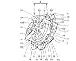
- a special thread mill 1E shown in FIG. 28includes a body 2B and an insert portion 3.
- the insert part 3is configured by combining an insert 9 for an end mill with the insert 4 of the above embodiment.
- the insert 9includes an insert body 500 and four blade portions 511 to 514.
- the insert body 500is formed in a substantially disk shape having a predetermined thickness, and includes one surface 500A and the other surface 500B.
- the insert body 500includes a shaft hole 501 and four insertion holes 521 to 524.
- the shaft hole 501is provided at the center of the insert body 500 and penetrates the one surface 500A and the other surface 500B.
- a boss 211(see FIG. 14) provided at the tip of the body 2B is inserted into the shaft hole 501.
- the four blade portions 511 to 514are respectively provided on one surface 500A of the insert main body 500, and are arranged at equal intervals in the circumferential direction around the shaft hole 501.
- the blade portions 511 to 514are formed in a substantially fan shape when viewed from the axial front end side.
- the insertion holes 521 to 524are respectively provided at the substantially central portions of the blade portions 511 to 514. In these insertion holes 521 to 524, four screws 8 (see FIG. 28) are inserted.
- the other surface 500B of the insert body 500is provided with eight convex portions 531 and eight concave portions 532 alternately in the circumferential direction around the shaft hole 501, for example, provided on both surfaces of the insert 5 of the above embodiment. The same uneven shape as the formed uneven shape is formed. These eight convex parts 531 and eight concave parts 532 satisfy the arrangement conditions of the convex parts and the concave parts of the above embodiment.
- the other surface 500B of the insert 9 having the uneven shapeis opposed to the one surface 10A of the insert 4 and overlapped with each other.
- the other surface 500B and the one surface 50Abecome the mating surfaces.
- the eight convex portions 531 provided on the other surface 500Bare inserted into the concave portions 31 to 38 provided on the one surface 10A, respectively.
- the convex portions 21 to 28 provided on the one surface 10Aare respectively inserted into the eight concave portions 532 provided on the other surface 500B. In this way, the inserts 4 and 9 are coaxially overlapped with each other to form the insert portion 3.
- the special thread mill 1Eis configured by bringing the insert 4 side of the insert portion 3 into contact with the mounting surface 190 of the body 2B and mounting with the four screws 8 (FIG. 28). reference). In addition, it can overlap
- FIG.Such a special thread mill 1E can obtain the same effects as the thread mill 1A of the above embodiment.
- the present inventioncan be variously modified in addition to the above modification.
- the said embodimentis a thread mill, it is applicable also to other tools, such as a T slot cutter, a reamer, an end mill, for example.
- the insert portion 3 of the above embodimentis configured by superimposing the two inserts 4 and 5 on the same axis, but may be configured by one, and may be configured by overlapping three or more on the same axis. May be.
- the insert 4 or 5is fixed to the mounting surfaces 90 and 190 of the bodies 2A and 2B with the four screws 8.
- the insert 4 or 5may be detachably fixed by other means.
- the insertmay be fixed to the body with a single bolt.
- the bossis projected from the shaft hole of the insert arranged on the mounting surface of the body, and the bolt shaft portion is fastened to the screw hole provided at the tip of the boss.
- the number of protrusions and recesses provided in each of the inserts 4 and 5is eight, but the number is not limited as long as the number is the same.
- the tips of the convex portions 61 to 68 provided on the mating surface of the insert 5contact the bottoms of the concave portions 31 to 38 provided on the mating surface of the insert 4. Although it is made not to do, you may make it contact. On the contrary, the tips of the projections 61 to 68 provided on the mating surface of the insert 5 are brought into contact with the bottoms of the recesses 31 to 38 provided on the mating surface of the insert 4 to align the insert 4. The tips of the convex portions 21 to 28 provided on the surface may not contact the bottoms of the concave portions 71 to 78 provided on the mating surface of the insert 5.
- the tip portions of the convex portions 61 to 68 provided on the other surface 50B of the insert 5do not come into contact with the bottom portions of the concave portions 101 to 108 provided on the mounting surface 90 of the body 2A. It may be contacted.
- the tip portions of the convex portions 21 to 28 provided on the other surface 10B of the insert 4are in contact with the bottoms of the concave portions 201 to 208 provided on the mounting surface 190 of the body 2B. However, you may make it not contact.
- the spacer 300 shown in FIG. 26includes four blade portions 311 to 314, but the number of blade portions is not limited.
Landscapes
- Engineering & Computer Science (AREA)
- Mechanical Engineering (AREA)
- Milling Processes (AREA)
- Toys (AREA)
Abstract
Description
Translated fromJapanese本発明は、ボディと、該ボディに取り付けられるインサート部とを備えるインサート式工具及びスレッドミルに関する。The present invention relates to an insert-type tool and a thread mill including a body and an insert portion attached to the body.
ホルダと加工ヘッドが、締結用おねじと締結用めねじで一体的に結合される加工ヘッド交換式回転工具が提案されている(例えば、特許文献1参照)。A machining head exchangeable rotary tool in which a holder and a machining head are integrally coupled with a fastening male screw and a fastening female screw has been proposed (see, for example, Patent Document 1).
特許文献1に記載の加工ヘッド交換式回転工具では、ホルダの形状によって使用用途が限定されてしまうという問題点があった。また、加工ヘッド交換式回転工具は、様々な形状の加工ヘッドを使用できるが、取付可能な加工ヘッドの数は一つであるので、例えば荒加工と仕上げ加工を同時に行うような複合加工はできなかった。The machining head exchangeable rotary tool described in Patent Document 1 has a problem that the usage is limited by the shape of the holder. In addition, the machining head exchangeable rotary tool can use machining heads of various shapes, but since the number of machining heads that can be mounted is one, for example, complex machining such as roughing and finishing can be performed simultaneously. There wasn't.
本発明の目的は、様々な使用用途に適用でき、且つ複合加工を可能とするインサート式工具及びスレッドミルを提供することである。An object of the present invention is to provide an insert type tool and a thread mill that can be applied to various usages and can be combined.
本発明の第1態様によれば、円柱状のボディと、円盤状のインサート部と、前記ボディの軸方向の一端部に前記インサート部を着脱可能に固定する固定手段とを備え、前記インサート部は、刃部を外周に備える円盤状のインサートを一枚で、又は複数枚を互いに同軸上に重ね合わせて構成することが可能であって、前記インサートは両面の夫々に、前記インサートの厚み方向の中心から前記厚み方向の両側に夫々突出して形成され、前記中心から最も離間する凸部と、前記凸部を除く部分に設けられ、前記中心から前記厚み方向の両側に夫々突出して形成され、前記凸部よりも低い凹部とを備え、複数枚の前記インサートを互いに同軸上に重ね合わせたときに、互いに重なり合う第1インサートと第2インサートの夫々の合わせ面において、前記第1インサートの前記合わせ面に設けられた前記凸部は、前記第2インサートの前記合わせ面に設けられた前記凹部内に挿入され、前記第2インサートの前記合わせ面に設けられた前記凸部は、前記第1インサートの前記合わせ面に設けられた前記凹部内に挿入されることを特徴とするインサート式工具が提供される。According to the first aspect of the present invention, the insert portion includes a columnar body, a disc-shaped insert portion, and a fixing means for detachably fixing the insert portion to one end portion in the axial direction of the body. Can be configured with a single disc-shaped insert having a blade portion on the outer periphery, or a plurality of disc-shaped inserts that are coaxially overlapped with each other. Projecting from the center to both sides in the thickness direction, the convex portion being the most spaced from the center, and provided at a portion excluding the convex portion, and formed to project from the center to both sides in the thickness direction, A concave portion that is lower than the convex portion, and when the plurality of inserts are coaxially overlapped with each other, each mating surface of the first insert and the second insert that overlap each other The convex portion provided on the mating surface of the first insert is inserted into the concave portion provided on the mating surface of the second insert, and the convex portion provided on the mating surface of the second insert. The part is inserted into the recess provided in the mating surface of the first insert. An insert type tool is provided.
第1態様のインサート式工具は、インサート部を、複数枚のインサートを同軸上に重ね合わせて構成できる。それ故、種類の異なる複数のインサートを重ね合わせることで、ワークに対し複合加工を施すことができる。さらに、インサート部におけるインサートの組み合わせを変えることで、複合加工のバリエーションを広げることができる。インサート部は一枚でも構成できるので、使用用途に応じて適切な一枚のインサートを、ボディの一端部に取り付けて使用できる。互いに重ね合わされた第1インサートと第2インサートの夫々の合わせ面において、第1インサート側の凸部は、第2インサート側の凹部に挿入され、第2インサート側の凸部は、第1インサート側の凹部に挿入される。第1インサートと第2インサートは、夫々の厚み方向において互いに一部が重なる。よって、第1インサートと第2インサートを重ね合わせたときのインサート部の厚みは、第1インサートと第2インサートの夫々の単体の厚みの合計よりも小さくなる。従って、第1態様は、インサート部の突出長を短くできるので、工具剛性を向上できる。さらに、回転時に生じる振れを抑制できる。In the insert tool of the first aspect, the insert portion can be configured by overlapping a plurality of inserts on the same axis. Therefore, a composite process can be performed on the workpiece by overlapping a plurality of different types of inserts. Furthermore, the variation of a composite process can be expanded by changing the combination of the insert in an insert part. Since even one insert part can be configured, an appropriate one insert can be attached to one end of the body for use. In each of the mating surfaces of the first insert and the second insert overlapped with each other, the convex portion on the first insert side is inserted into the concave portion on the second insert side, and the convex portion on the second insert side is the first insert side. Inserted into the recess. The first insert and the second insert partially overlap each other in the thickness direction. Therefore, the thickness of the insert portion when the first insert and the second insert are overlapped is smaller than the total thickness of each of the first insert and the second insert. Therefore, since the protrusion length of an insert part can be shortened in the 1st mode, tool rigidity can be improved. Furthermore, it is possible to suppress the shake that occurs during rotation.
第1態様の前記凸部は、前記刃部と前記インサートの中心部との間に設けられていてもよい。第1態様は、インサートのうち厚みのある凸部を、インサートの外周に設けられた刃部に対応して配置するので、刃部を支持するインサートの外周部分の剛性を向上できる。The convex portion of the first aspect may be provided between the blade portion and the center portion of the insert. Since the 1st aspect arrange | positions the convex part with thickness among inserts corresponding to the blade part provided in the outer periphery of insert, the rigidity of the outer peripheral part of the insert which supports a blade part can be improved.
第1態様の前記インサートの前記中心部には、前記厚み方向に貫通する軸穴が設けられ、前記ボディの前記一端部には、前記インサートの片面と接触する接触面が設けられ、前記接触面の中心には、前記ボディの軸方向に沿って突出し、前記軸穴に挿入されるボスが設けられていてもよい。インサートをボディの一端部に固定するとき、ボディ側のボスをインサートの軸穴に挿入し、インサートの片面をボディ側の接触面に接触させた状態で、固定手段で固定する。これにより、第1態様は、ボディの一端部に対してインサートを簡単に位置決めできるので、ボディに対するインサートの取付作業を効率よく行うことができる。The center portion of the insert of the first aspect is provided with a shaft hole penetrating in the thickness direction, and the one end portion of the body is provided with a contact surface that contacts one side of the insert, and the contact surface A boss that protrudes along the axial direction of the body and is inserted into the shaft hole may be provided at the center of the body. When the insert is fixed to one end of the body, the boss on the body side is inserted into the shaft hole of the insert, and is fixed by a fixing means in a state where one side of the insert is in contact with the contact surface on the body side. Thereby, since a 1st aspect can position an insert easily with respect to the one end part of a body, the attachment operation | work of an insert with respect to a body can be performed efficiently.
第1態様の前記接触面には、前記片面に設けられた前記凹部に対応する位置に、前記片面側に突出して設けられ、前記凹部内に挿入されるボディ側凸部と、前記片面に設けられた前記凸部に対応する位置に、前記ボディ側凸部よりも低く設けられ、前記凸部を内側に挿入させるボディ側凹部とが夫々設けられていてもよい。接触面にインサートの片面を接触させるとき、インサートの片面に設けられた凸部を、接触面に設けられたボディ側凹部内に挿入できる。これにより、第1態様は、インサート部の突出長をさらに短くできる。The contact surface of the first aspect is provided with a body-side convex portion that protrudes from the one surface side and is inserted into the concave portion at a position corresponding to the concave portion provided on the one surface, and is provided on the one surface. The body side recessed part which is provided lower than the said body side convex part and inserts the said convex part inside may be provided in the position corresponding to the said convex part. When the one surface of the insert is brought into contact with the contact surface, the convex portion provided on the one surface of the insert can be inserted into the body-side concave portion provided on the contact surface. Thereby, the 1st aspect can further shorten the protrusion length of an insert part.
第1態様の前記固定手段はネジであって、前記インサートには、前記厚み方向に貫通し、前記ネジの軸部を挿入する為の挿入穴が設けられ、前記接触面において前記挿入穴に対応する位置には、前記ネジを締結する為のネジ穴が設けられていてもよい。これにより、第1態様は、インサートをボディに対して強固に固定できる。The fixing means of the first aspect is a screw, and the insert is provided with an insertion hole through which the shaft portion of the screw penetrates in the thickness direction, and corresponds to the insertion hole on the contact surface. A screw hole for fastening the screw may be provided at the position to be used. Thereby, the 1st mode can fix an insert to a body firmly.
第1態様の前記第1インサートの前記合わせ面に設けられた前記凸部の先端部は、前記第2インサートの前記合わせ面に設けられた前記凹部の底部と当接し、前記第2インサートの前記合わせ面に設けられた前記凸部の先端部は、前記第1インサートの前記合わせ面に設けられた前記凹部の底部とは接触しないようにしてもよい。これにより、第1態様は、第1インサートの合わせ面と第2インサートの合わせ面をがたつくことなく平行に重ね合わせることができるので、複数枚のインサートで構成されたインサート部の厚みを均一にできる。The tip of the convex portion provided on the mating surface of the first insert of the first aspect contacts the bottom of the concave portion provided on the mating surface of the second insert, and the second insert You may make it the front-end | tip part of the said convex part provided in the mating surface not contact with the bottom part of the said recessed part provided in the said mating surface of a said 1st insert. Thereby, since the 1st aspect can superimpose the mating surface of a 1st insert and the mating surface of a 2nd insert in parallel, it can make the thickness of the insert part comprised by several inserts uniform. .
第1態様の前記インサートの両面の夫々において、前記凸部の数と前記凹部の数は同一のn個であり、前記インサートの中心部から前記凸部の最外周縁部と接触し、且つ前記凸部を間に全て含むときの二本の第1仮想直線が示す最小角度をX、前記中心部から前記凹部の最外周縁部と接触する二本の第2仮想直線の間に前記凸部を含まないときの最大角度をYとした場合、X<Yであり、n個の前記凸部の夫々のXの合計は180°未満であり、n個の前記凹部の夫々のYの合計は180°より大きく、n個の前記凸部の夫々のXのうち最大角度Xmaxは180/n未満であり、n個の前記凹部の夫々のYのうち最大角度Ymaxは180/nよりも大きくなるようにしてもよい。これにより、インサートの両面の夫々に設けられた凸部と凹部は、インサートを裏返しても、他方のインサートの凹部と凸部と重なることができる。In each of both surfaces of the insert of the first aspect, the number of the convex portions and the number of the concave portions are the same n, and contacts the outermost peripheral edge portion of the convex portion from the center portion of the insert, and X is the minimum angle indicated by the two first virtual lines when all of the convex parts are included in between, and the convex parts between the two second virtual lines that come into contact with the outermost peripheral edge of the concave part from the central part X <Y, and the total X of each of the n convex portions is less than 180 °, and the total Y of each of the n concave portions is More than 180 °, the maximum angle Xmax of each X of the n convex portions is less than 180 / n, and the maximum angle Ymax of each Y of the n concave portions is more than 180 / n. It may be made larger. Thereby, the convex part and recessed part provided in each of both surfaces of the insert can overlap with the concave part and convex part of the other insert even if the insert is turned upside down.
第1態様の前記インサートの両面の夫々において、前記インサート部は、荒加工用の刃部を備える前記インサートである荒加工用インサートと、仕上げ加工用の刃部を備える前記インサートである仕上げ加工用インサートとを同軸上に互い重ね合わせて構成してもよい。これにより、第1態様は、荒加工と仕上げ加工を同時に行う複合加工をワークに施すことができる。In each of both surfaces of the insert of the first aspect, the insert part is a roughing insert that is the insert having a roughing blade part, and the insert that is the insert having a finishing blade part. The inserts may be configured to overlap each other on the same axis. Thereby, the 1st aspect can give the workpiece the combined processing which performs roughing and finishing simultaneously.
第1態様の前記インサート部を複数枚の前記インサートを重ね合わせて構成した場合に、厚みの異なる前記インサートと入れ替え交換することで、前記第1インサートの外周に設けられた前記刃部と、前記第2インサートの外周に設けられた前記刃部との前記軸方向に平行な距離であるピッチを調節可能としてもよい。これにより、第1態様は、インサート部において、厚みの異なるインサートを重ねることで、ピッチを簡単に調節できる。When the insert portion of the first aspect is configured by overlapping a plurality of the inserts, the blade portion provided on the outer periphery of the first insert by replacing and replacing the insert with a different thickness, A pitch that is a distance parallel to the axial direction with the blade provided on the outer periphery of the second insert may be adjustable. Thereby, a 1st aspect can adjust a pitch easily by overlapping the insert from which thickness differs in an insert part.
第1態様は、前記第1インサートと前記第2インサートとの間に重ねる板状のスペーサを備えてもよい。第1態様は、第1インサートと第2インサートの間にスペーサを重ねることで、インサート部のピッチを簡単に変更できる。また、異なる厚みのスペーサを重ねることで、ピッチを簡単に調節できる。The first aspect may include a plate-like spacer that overlaps between the first insert and the second insert. In the first aspect, the pitch of the insert portion can be easily changed by overlapping the spacer between the first insert and the second insert. Further, the pitch can be easily adjusted by stacking spacers having different thicknesses.
本発明の第2態様のスレッドミルは、請求項1から10の何れかに記載のインサート式工具の構成を備えたことを特徴とするスレッドミルを提供できる。これにより、第2態様のスレッドミルは、請求項1から10の何れかに記載の効果を奏することができる。The thread mill according to the second aspect of the present invention can provide a thread mill characterized by including the configuration of the insert-type tool according to any one of claims 1 to 10. Thereby, the thread mill of a 2nd aspect can show the effect in any one of Claims 1-10.
以下、本発明の実施形態を図面を参照して説明する。なお、本発明は、以下説明する実施形態の具体的構成に何ら限定されるものではない。Hereinafter, embodiments of the present invention will be described with reference to the drawings. In addition, this invention is not limited to the specific structure of embodiment described below at all.
図1を参照し、スレッドミル1Aの構造を説明する。スレッドミル1Aは、ワーク7(図22参照)に設けられた穴6に対し、ミリング加工でめねじを切削する為の工具である。スレッドミル1Aはインサート式工具であり、略円柱状のボディ2Aと、該ボディ2Aの先端部(軸線方向一端部)に着脱可能に固定されたインサート部3とを備える。ボディ2Aは、図示しない工作機械の主軸等に取り付けられて回転駆動されるシャンクである。ボディ2Aの材質は、例えばインサート部3を構成する後述するインサート4,5に比較して耐摩耗性、硬さ、強度等が低い炭素鋼、合金鋼等を採用できる。The structure of the
インサート部3は、ボディ2Aの先端部に対し、4本のネジ8で着脱可能に固定されている。インサート部3は、一枚、又は複数枚の円盤状のインサートを同軸上に重ね合わせて構成される。図1に示すインサート部3は、2枚のインサート4,5を同軸上に重ね合わせて構成されている。インサート4,5は、超硬合金、セラミック、又は高速度工具鋼等の所定材料で形成される。また、必要に応じてTiNやTiCN、TiAlN、CrN等の化合物被膜やDLC(Diamond Like Carbon;ダイヤモンド状カーボン)膜、ダイヤモンド被膜等の硬質被膜をコーティングしてもよく、水蒸気処理、窒化処理等を施してもよい。The
インサート4,5は、例えば、使用用途が互いに異なるものを採用できる。インサート4は仕上げ加工用、インサート5は荒加工用である。インサート部3は、インサート4を軸線方向先端側に、インサート5を軸線方向後端側に備える。このようなインサート部3を備えるスレッドミル1Aは、ワーク7に設けられた穴6に対し、右刃ダウンカットで右ねじを切削する工具として使用される(図22参照)。このスレッドミル1Aは、右刃ダウンカットの1パスで、荒加工と仕上げ加工を同時に行う複合加工を行うことができる。The
図2~4を参照し、インサート4の構造を具体的に説明する。なお、図4は、図3に示すインサート4を矢印D1方向から見たときの側面図である。図2,図3に示すように、インサート4は、インサート本体10と、8つの刃部11~18とを備える。インサート4は仕上げ加工用であるので、後述する荒加工用のインサート5よりも径が小さい。インサート本体10は、所定厚を有する略円盤状に形成され、一面10Aと他面10B(図4参照)を備える。インサート本体10は、軸穴41と4つの挿入穴43~46を備える。軸穴41は、インサート本体10の中心部に設けられ、一面10Aと他面10Bを貫通する。軸穴41には、ボディ2Aの先端部に設けられた後述するボス111(図12参照)が挿入される。4つの挿入穴43~46は、軸穴41を中心に十字の方向に夫々配置され、且つ後述する刃部12,14,16,18に夫々対応する位置に設けられている。これら挿入穴43~46には、4本のネジ8(図1参照)が挿入される。The structure of the
刃部11~18は、インサート本体10の外周縁部において、周方向に互いに等間隔に設けられている。なお、説明の便宜上、刃部11~18は、インサート本体10を一面10Aから見たときに、時計回りに順に配置されているものとする。刃部11~18は、周方向から見て径方向外側に突出する略三角形状に形成されている。刃部11~18の刃先11A~18Aは、一面10A側から見たときの周方向左側(他面10Bから見たときの周方向右側)に夫々配置されている。The
次に、インサート本体10の表面形状を説明する。一面10Aと他面10Bには、8つの略扇型状の凸部21~28と、8つの略扇型状の凹部31~38と、環状凹部39とが、夫々設けられている。一面10Aと他面10Bの夫々において、凸部21~28は、刃部11~18に夫々対応する位置に設けられている。凸部21は、刃部11と軸穴41の間に、インサート本体10の厚み方向に突出して設けられ、刃部11の基部から軸穴41側に向かって先細りに形成されている。凸部22は、刃部12と挿入穴43の間に、インサート本体10の厚み方向に突出して設けられ、刃部12の基部から挿入穴43側に向かって先細りに形成されている。Next, the surface shape of the
凸部23,25,27は、凸部21と同様に、刃部13,15,17と軸穴41との間において、インサート本体10の厚み方向に突出して設けられ、刃部13,15,17の基部から軸穴41側に向かって先細りに形成されている。また、凸部24,26,28は、凸部22と同様に、挿入穴44,45,46と、刃部14,16,18との間において、インサート本体10の厚み方向に突出して設けられ、刃部14,16,18の夫々の基部から挿入穴44,45,46側に向かって先細りに形成されている。Similarly to the
一面10Aと他面10Bにおいて、凹部31~38は、凸部21~28を除く部分で、且つ凸部21~28の夫々の間に設けられ、インサート本体10の厚み方向において、凸部21~28よりも低く形成されている。凹部31は、凸部21と22の間に設けられ、インサート本体10の外周縁部から軸穴41側に向かって先細りに形成されている。そして、凹部31と同様に、凹部32は、凸部22と23の間に設けられ、凹部33は、凸部23と24の間に設けられ、凹部34は、凸部24と25の間に設けられ、凹部35は、凸部25と26の間に設けられ、凹部36は、凸部26と27の間に設けられ、凹部37は、凸部27と28の間に設けられ、凹部38は、凸部28と21の間に設けられ、インサート本体10の外周縁部から軸穴41側に向かって先細りに夫々形成されている。環状凹部39は、軸穴41の外周縁部に沿って環状に、且つ凸部21~28よりも低く形成され、凹部31~38の夫々の軸穴41側の端部と接続する。環状凹部39と凹部31~38は、互いに同一平面である。図4に示すように、一面10Aに設けられた凸部21~28及び凹部31~38と、他面10Bに設けられた凸部21~28及び凹部31~38とは、インサート10本体の厚み方向において互いに同一位置に夫々配置されている。On the one
図4に示すように、上記構造を備えるインサート4において、インサート本体10の厚み方向の中心から一面10A側の凸部21~28の各先端部までの長さをM1、他面10B側の凸部21~28の各先端部までの長さをM2、インサート本体10の厚み方向の中心から一面10A側の凹部31~38の各底部までの長さをN1、インサート本体10の厚み方向の中心から他面10B側の凹部31~38の各底部までの長さをN2とする。インサート4の厚みL1は、一面10A側の凸部21~28から、他面10B側の凸部21~28までの長さであるので、M1とM2を加算した長さである。このとき、インサート4は、M1=M2、M1>M2、M1<M2、N1=N2、N1>N2、N1<N2の何れの場合も適用可能である。As shown in FIG. 4, in the
図5~7を参照し、インサート5の構造を具体的に説明する。なお、図7は、図6に示すインサート5を矢印D3方向から見たときの側面図である。図5,図6に示すように、インサート5は、インサート本体50と、8つの刃部51~58とを備える。インサート本体50は、所定厚を有する略円盤状に形成され、一面50Aと他面50B(図7参照)を備える。インサート本体50は、軸穴81と4つの挿入穴83~86を備える。軸穴81は、インサート本体50の中心部に設けられ、一面50Aと他面50Bを貫通する。軸穴81には、ボディ2Aの先端部に設けられた後述するボス111(図12参照)が挿入される。4つの挿入穴83~86は、軸穴81を中心に十字の方向に夫々配置され、刃部51と52の間、刃部53と54の間、刃部55と56の間、刃部57と58の間に夫々対応する各位置に設けられている。これら挿入穴83~86には、4本のネジ8(図1参照)が挿入される。The structure of the
刃部51~58は、インサート本体50の外周縁部において、周方向に互いに等間隔に設けられている。なお、説明の便宜上、刃部51~58は、インサート本体50を一面50Aから見たときに、時計回りに順に配置されているものとする。刃部51~58は、周方向から見て径方向外側に突出する略三角形状に形成されている。刃部51~58の刃先51A~58Aは、一面50A側から見たときの周方向左側(他面50Bから見たときの周方向右側)に夫々配置されている。The
次に、インサート本体50の表面形状を説明する。一面50Aと他面50Bには、8つの略扇型状の凸部61~68と、8つの略扇型状の凹部71~78と、環状凹部79とが、夫々設けられている。一面50Aと他面50Bの夫々において、凸部61~68は、刃部51~58に夫々対応する位置に設けられている。凸部61は、刃部51と軸穴81の間に、インサート本体50の厚み方向に突出して設けられ、刃部51の基部から軸穴81側に向かって先細りに形成されている。凸部61の挿入穴83と重複する部分は、挿入穴83の湾曲する外縁部に沿って湾曲して形成されている。凸部62は、刃部52と軸穴81の間に、インサート本体50の厚み方向に突出して設けられ、刃部52の基部から軸穴81側に向かって先細りに形成されている。凸部62の挿入穴83と重複する部分は、挿入穴83の湾曲する外縁部に沿って湾曲して形成されている。Next, the surface shape of the
なお、凸部61,62と同様に、凸部63,64は、刃部53,54と軸穴81の間に、インサート本体50の厚み方向に突出して設けられ、刃部53,54の基部から軸穴81に向かって先細りに形成されている。凸部63,64の挿入穴84と重複する部分は、挿入穴84の湾曲する外縁部に沿って夫々湾曲して形成されている。凸部65,66は、刃部55,56と軸穴81の間に、インサート本体50の厚み方向に突出して設けられ、刃部55,56の基部から軸穴81側に向かって先細りに形成されている。凸部65,66の挿入穴85と重複する部分は、挿入穴85の湾曲する外縁部に沿って夫々湾曲して形成されている。凸部67,68は、刃部57,58と軸穴81の間に、インサート本体50の厚み方向に突出して設けられ、刃部57,58の基部から軸穴81に向かって先細りに形成されている。凸部67,68の挿入穴86と重複する部分は、挿入穴86の湾曲する外縁部に沿って夫々湾曲して形成されている。Similar to the
一面50Aと他面50Bにおいて、凹部71~78は、凸部61~68を除く部分で、且つ凸部61~68の夫々の間に設けられ、インサート本体50の厚み方向において、凸部61~68よりも低く形成されている。凹部71は、凸部61と62の間に設けられ、凹部72は、凸部62と63の間に設けられ、凹部73は、凸部63と64の間に設けられ、凹部74は、凸部64と65の間に設けられ、凹部75は、凸部65と66の間に設けられ、凹部76は、凸部66と67の間に設けられ、凹部77は、凸部67と68の間に設けられ、凹部78は、凸部68と61の間に設けられている。凹部71~78は、夫々、インサート本体50の外周縁部から軸穴81側に向かって先細りに形成されている。On the one
挿入穴83~86は、凹部71,73,75,77の夫々の軸穴81側に設けられている。環状凹部79は、軸穴81の外周縁部に沿って環状に、且つ凸部61~68よりも低く形成され、凹部71~78の夫々の軸穴81側の端部と接続する。環状凹部79と凹部71~78は、互いに同一平面である。図7に示すように、一面50Aに設けられた凸部61~68及び凹部71~78と、他面50Bに設けられた凸部61~68及び凹部71~78とは、インサート本体50の厚み方向において互いに同一位置に夫々配置されている。The insertion holes 83 to 86 are provided on the
上記構造を備えるインサート5において、インサート本体50の厚み方向の中心から一面50A側の凸部61~68の各先端部までの長さをM3、他面50B側の凸部61~68の各先端部までの長さをM4、インサート本体50の厚み方向の中心から一面50A側の凹部71~78の各底部までの長さをN3、インサート本体50の厚み方向の中心から他面50B側の凹部71~78の各底部までの長さをN4とする。インサート5の厚みL2は、一面50A側の凸部61~68から、他面50B側の凸部61~68までの長さであるので、M3とM4を加算した長さである。このとき、インサート5は、M3=M4、M3>M4、M3<M4、N3=N4、N3>N4、N3<N4の何れの場合も適用可能である。In the
図8,図9を参照し、インサート4と5を重ね合わせてインサート部3を作成する方法を説明する。なお、図8に示すインサート4は、図3のインサート4を矢印D2方向から見たときの側面を示す。図8に示すインサート5は、図6のインサート5を矢印D4方向から見たときの側面を示す。図9では、インサート5を実線、インサート4を二点鎖線で示している。Referring to FIGS. 8 and 9, a method for creating the
図8に示すように、例えば、インサート4の他面10Bと、インサート5の一面50Aを対向させ、互いに重ね合わせる。このとき、他面10Bと一面50Aが合わせ面となる。As shown in FIG. 8, for example, the
図8,図9に示すように、他面10Bに設けられた凸部21は、一面50Aに設けられた凹部78に挿入される。他面10Bに設けられた凸部22は、一面50Aに設けられた凹部71に挿入される。他面10Bに設けられた凸部23は、一面50Aに設けられた凹部72に挿入される。他面10Bに設けられた凸部24は、一面50Aに設けられた凹部73に挿入さる。他面10Bに設けられた凸部25は、一面50Aに設けられた凹部74に挿入される。他面10Bに設けられた凸部26は、一面50Aに設けられた凹部75に挿入される。他面10Bに設けられた凸部27は、一面50Aに設けられた凹部76に挿入される。他面10Bに設けられた凸部28は、一面50Aに設けられた凹部77に挿入される。8 and 9, the
一方、一面50Aに設けられた凸部61は、他面10Bに設けられた凹部31に挿入される。一面50Aに設けられた凸部62は、他面10Bに設けられた凹部32に挿入される。一面50Aに設けられた凸部63は、他面10Bに設けられた凹部33に挿入される。一面50Aに設けられた凸部64は、他面10Bに設けられた凹部34に挿入される。一面50Aに設けられた凸部65は、他面10Bに設けられた凹部35に挿入される。一面50Aに設けられた凸部66は、他面10Bに設けられた凹部36に挿入される。一面50Aに設けられた凸部67は、他面10Bに設けられた凹部37に挿入される。一面50Aに設けられた凸部68は、他面10Bに設けられた凹部38に挿入される。このようにして、インサート4と5が同軸上に互いに重ね合わされ、インサート部3が構成される。On the other hand, the
ここで、インサート部3では、他面10Bに設けられた凸部21の先端部が、一面50Aに設けられた凹部78の底部と当接する。他面10Bに設けられた凸部22の先端部が、一面50Aに設けられた凹部71の底部と当接する。他面10Bに設けられた凸部23の先端部が、一面50Aに設けられた凹部72の底部と当接する。他面10Bに設けられた凸部24の先端部が、一面50Aに設けられた凹部73の底部と当接する。他面10Bに設けられた凸部25の先端部が、一面50Aに設けられた凹部74の底部と当接する。他面10Bに設けられた凸部26の先端部が、一面50Aに設けられた凹部75の底部と当接する。他面10Bに設けられた凸部27の先端部が、一面50Aに設けられた凹部76の底部と当接する。他面10Bに設けられた凸部28の先端部が、一面50Aに設けられた凹部77の底部と当接する。Here, in the
一方、他面50Bに設けられた凸部61の先端部は、一面50Aに設けられた凹部31の底部に対して隙間を空けて対向する。他面50Bに設けられた凸部62の先端部は、一面50Aに設けられた凹部32の底部に対して隙間を空けて対向し、他面50Bに設けられた凸部63の先端部は、一面50Aに設けられた凹部33の底部に対して隙間を空けて対向する。他面50Bに設けられた凸部64の先端部は、一面50Aに設けられた凹部34の底部に対して隙間を空けて対向する。他面50Bに設けられた凸部65の先端部は、一面50Aに設けられた凹部35の底部に対して隙間を空けて対向する。他面50Bに設けられた凸部66の先端部は、一面50Aに設けられた凹部36の底部に対して隙間を空けて対向する。他面50Bに設けられた凸部67の先端部は、一面50Aに設けられた凹部37の底部に対して隙間を空けて対向する。他面50Bに設けられた凸部68の先端部は、一面50Aに設けられた凹部38の底部に対して隙間を空けて対向する。On the other hand, the tip of the
図8に示すように、インサート部3の厚みL3は、インサート4の一面10Aに設けられた凸部21~28の各先端部と、インサート5の他面50Bに設けられた凸部61~68の各先端部との間の距離に相当する。そして、上記のように、他面10Bと一面50Aの夫々の凸部と凹部が互いに重ね合されることで、インサート4の他面10B側の厚みM2と、インサート5の一面50A側の厚みM3とを、インサート部3の厚み方向において互いに重ねることができる。即ち、スレッドミル1Aは、インサート部3の厚みL3を、インサート4の厚みL1(図4参照)とインサート5の厚みL2(図7参照)を加算した距離よりも短くすることができる。例えば、インサート4の厚みが5mm、インサート5の厚みが4mmのとき、インサート4,5の単体の厚みの合計が9mmに対し、重ねた状態での厚みの合計は8mmとなる。なお、この場合のインサート4と5の厚み方向において互いに重なる長さは1mmである。これにより、スレッドミル1Aは、インサート部3の軸線方向における突出長を短くできるので、インサート部3の剛性を向上できる。さらに、インサート部3の剛性を向上できるので、スレッドミル1Aの回転時に生じる振れを抑制できる。As shown in FIG. 8, the thickness L3 of the
また、上記のように、インサート4の他面10Bの凸部21~28の先端部は、インサート5の一面50Aの凹部71~78の底部と夫々当接するが、インサート5側の凸部61~68の先端部は、インサート4の凹部31~38の底部とは接触しない。これは、インサート5の凸部61~68の高さの方が、インサート4の凹部31~38の深さよりも低いからである。なお、凸部の高さとは、凹部との高低差であり、凹部の底部から凸部の先端部までの長さである。凹部の深さとは、凸部との高低差であり、凸部の先端部から凹部の底部までの長さである。これにより、インサート部3は、インサート4と5を偏りなく互いに平行に重ね合わせることができるので、ピッチP1を揃えることができる。ピッチP1は、インサート4の刃部11~18と、インサート5の刃部51~58との間の距離である。なお、ピッチP1は、ワーク7の穴6(図22参照)に切削するねじのピッチに対応する。Further, as described above, the tip portions of the
図10,図11を参照し、インサートにおける凸部と凹部の配置条件を説明する。図8に示すインサート4と5の夫々の合わせ面に設けられた凸部と凹部は、インサート4,5の一方、又は両方を裏返しても、互いに重ね合わせることができる。その為には、インサートの両面に設ける凸部と凹部を、後述する配置条件に従って配置する必要がある。そこで、図10,図11に示すインサート130を例に、凸部と凹部の配置条件を説明する。なお、図10は、図11のインサート130を矢印D5方向から見たときの側面図である。Referring to FIG. 10 and FIG. 11, the arrangement conditions of the convex portion and the concave portion in the insert will be described. The convex portions and the concave portions provided on the mating surfaces of the
インサート130は、円盤状のインサート本体140を備える。なお、図10,図11では、インサート130に設けられる刃部、軸穴、挿入穴を省略している。インサート本体140は、一面140Aと他面140Bを備える。一面140Aと他面140Bの表面形状は同一である。The
図11に示すように、一面140Aには、中心Oを取り囲むようにして時計回りに、5つの凸部141~145と、5つの凹部151~155とが交互に配置されている。次いで、中心Oから凸部141の周方向両側の最外周縁部に夫々接触する仮想直線A1とA2を引き、これら仮想直線A1とA2の間に凸部141を全て含むときの最小角度をX1とする。そして、凸部141と同様に、凸部142の最外周縁部に夫々接触する2本の仮想直線の最小角度をX2、凸部143の最外周縁部に夫々接触する2本の仮想直線の最小角度をX3、凸部144の最外周縁部に夫々接触する2本の仮想直線の最小角度をX4、凸部145の最外周縁部に夫々接触する2本の仮想直線の最小角度をX5とする。なお、凸部141~145の夫々の形状は、2本の仮想直線の間であれば、どのような形状であってもよい。As shown in FIG. 11, on one
さらに、中心Oから凹部151の周方向両側の最外周縁部に夫々接触する2本の仮想直線B1とB2を引き、これら仮想直線B1とB2の間に凸部を含まないときの最大角度をY1とする。凹部151と同様に、凹部152の最外周縁部に夫々接触する2本の仮想直線の間に凸部を含まないときの最大角度をY2、凹部153の最外周縁部に夫々接触する2本の仮想直線の間に凸部を含まないときの最大角度をY3、凹部154の最外周縁部に夫々接触する2本の仮想直線の間に凸部を含まないときの最大角度をY4、凹部155の最外周縁部に夫々接触する2本の仮想直線の間に凸部を含まないときの最大角度をY5とする。Furthermore, the two virtual straight lines B1 and B2 that are in contact with the outermost peripheral edge portions on both sides in the circumferential direction of the
このような凸部と凹部を両面に備える2枚のインサート130を互いに重ね合わせてインサート部3を構成する場合に、一方を裏返しても他方と重ね合わせることができる為には、以下の5つの条件を満たすことが必要である。
(1)X1~X5の何れもY1~Y5より小さい
(2)凸部141~145の夫々のX1~X5の合計は180°未満
(3)凹部151~155の夫々のY1~Y5の合計は180°より大きい
(4)X1~X5のうち最大角度Xmaxは180/5°未満
(5)Y1~Y5のうち最大角度Ymaxは180/5°よりも大きいWhen two
(1) Any of X1 to X5 is smaller than Y1 to Y5 (2) The sum of X1 to X5 of each of the
さらに、X1+Y1、X2+Y2、X3+Y3、X4+Y4、X5+Y5が何れも360/5°と同じになる場合は等分割となる。この場合、一方のインサート130の合わせ面に設けられた凸部141~145と凹部151~155は、他方のインサート130の合わせ面に設けられた凹部151~155と凸部141~145に対して、どの位置でも干渉なく重ね合わせることができる。なお、本実施形態のインサート4,5は、上記の配置条件を何れも満たしている。よって、インサート部3において、インサート4,5の一方、又は両方を裏返しても互いに重ね合わせることができ、夫々の両面に設けられた凸部と凹部は、どの位置でも干渉無く重ね合わせることができる。Furthermore, when X1 + Y1, X2 + Y2, X3 + Y3, X4 + Y4, and X5 + Y5 are all equal to 360/5 °, equal division is performed. In this case, the
図12,図13を参照し、ボディ2Aの取付面90の形状を説明する。ボディ2Aは、先端部に円形状の取付面90を備える。取付面90には、インサート5(図5,図6参照)を着脱可能に取り付けることができる。取付面90には、ボス111と、4つのネジ穴113~116とが夫々設けられている。ボス111は、取付面90の中心部に設けられ、ボディ2Aの軸線上に沿って延びる略円柱状に形成されている。4つのネジ穴113~116は、ボス111を中心に十字の方向に夫々配置され、時計回りに順に配置されている。これらネジ穴113~116には、4本のネジ8(図1参照)が締結される。The shape of the mounting
取付面90は、インサート5の両面の凹凸形状に対応する凹凸形状を備える。取付面90には、8つの略扇型状の凸部91~98と、8つの略扇型状の凹部101~108と、環状凹部109とが、夫々設けられている。凸部91は、ネジ穴113と116の間の中央に、ボディ2Aの軸線方向に対して平行に突出して設けられ、取付面90の外周縁部からボス111側に向かって先細りに形成されている。凸部92は、ネジ穴113と外周縁部との間に、ボディ2Aの軸線方向に対して平行に突出して設けられ、外周縁部からネジ穴113に向かって先細りに形成されている。The mounting
また、凸部91と同様に、凸部93はネジ穴113と114の間の中央に、凸部95はネジ穴114と115の間の中央に、凸部97はネジ穴115と116の間の中央に、ボディ2Aの軸線方向に対して平行に突出して設けられ、取付面90の外周縁部からボス111側に向かって先細りに夫々形成されている。また、凸部92と同様に、凸部94はネジ穴114と外周縁部との間に、凸部96はネジ穴115と外周縁部との間に、凸部98はネジ穴116と外周縁部との間に、ボディ2Aの軸線方向に対して平行に突出して設けられ、取付面90の外周縁部からネジ穴114,115,116に向かって先細りに夫々形成されている。Similarly to the
一方、凹部101~108は、凸部91~98の夫々の間に設けられ、ボディ2Aの軸線方向において、凸部91~98よりも軸線方向後端側に低く形成されている。凹部101は、凸部91と92の間に設けられ、取付面90の外周縁部からボス111側に向かって先細りに形成されている。そして、凹部101と同様に、凹部102は、凸部92と93の間に設けられ、凹部103は、凸部93と94の間に設けられ、凹部104は、凸部94と95の間に設けられ、凹部105は、凸部95と96の間に設けられ、凹部106は、凸部96と97の間に設けられ、凹部107は、凸部97と98の間に設けられ、凹部108は、凸部98と91の間に設けられ、取付面90の外周縁部からボス111側に向かって先細りに夫々形成されている。On the other hand, the
環状凹部109は、ボス111の外周に沿って環状に設けられ、凹部101~108の夫々のボス111側の端部と接続する。環状凹部109は、ボディ2Aの軸線方向において、凹部101~108よりも低く形成されている。そして、取付面90の凸部91~98と凹部101~108も、上記の凸部と凹部の配置条件を満たしている。The
図13,図14,図16,図18を参照し、ボディ2Aに対してインサート部3を取り付ける方法を説明する。なお、ここでは、図18に示すスレッドミル1Aを作成することを目的として、インサート部3をボディ2Aに取り付ける方法を説明する。上記のように、ボディ2Aは、インサート5を取り付けることができる。それ故、ボディ2Aの取付面90に対して、インサート部3のうちインサート5の他面50B側を対向させる。次いで、取付面90のボス111を、インサート5の軸穴81、インサート4の軸穴41の順に挿入させる。そして、図18に示すように、インサート5の他面50Bを、取付面90に対して重ね合わせる。このとき、他面50Bと取付面90が合わせ面となる。A method for attaching the
図16では、ボディ2Aの取付面90を実線、インサート5を二点鎖線で示している。図16に示すように、インサート5の他面50Bに設けられた凸部61は、取付面90に設けられた凹部101に挿入される。他面50Bに設けられた凸部62は、取付面90に設けられた凹部102に挿入される。他面50Bに設けられた凸部63は、取付面90に設けられた凹部103に挿入される。他面50Bに設けられた凸部64は、取付面90に設けられた凹部104に挿入される。他面50Bに設けられた凸部65は、取付面90に設けられた凹部105に挿入される。他面50Bに設けられた凸部66は、取付面90に設けられた凹部106に挿入される。他面50Bに設けられた凸部67は、取付面90に設けられた凹部107に挿入される。他面50Bに設けられた凸部68は、取付面90に設けられた凹部108に挿入される。In FIG. 16, the mounting
一方、取付面90に設けられた凸部91は、他面50Bに設けられた凹部78に挿入される。取付面90に設けられた凸部92は、他面50Bに設けられた凹部71に挿入される。取付面90に設けられた凸部93は、他面50Bに設けられた凹部72に挿入される。取付面90に設けられた凸部94は、他面50Bに設けられた凹部73に挿入される。取付面90に設けられた凸部95は、他面50Bに設けられた凹部74に挿入される。取付面90に設けられた凸部96は、他面50Bに設けられた凹部75に挿入される。取付面90に設けられた凸部97は、他面50Bに設けられた凹部76に挿入される。取付面90に設けられた凸部98は、他面50Bに設けられた凹部77に挿入される。On the other hand, the
次いで、インサート4の挿入穴43~46と、インサート5の挿入穴83~86とに対して、4本のネジ8を夫々挿入し、取付面90のネジ穴113~116に夫々締結する。このようにして、ボディ2Aの取付面90に対し、インサート部3が固定され、スレッドミル1Aが構成される。Next, four
ここで、図16,図18に示すように、インサート5の他面50Bがボディ2Aの取付面90に取り付けられた状態では、取付面90に設けられた凸部91の先端部が、他面50Bに設けられた凹部78の底部と当接する。取付面90に設けられた凸部92の先端部が、他面50Bに設けられた凹部71の底部と当接する。取付面90に設けられた凸部93の先端部が、他面50Bに設けられた凹部72の底部と当接する。取付面90に設けられた凸部94の先端部が、他面50Bに設けられた凹部73の底部と当接する。取付面90に設けられた凸部95の先端部が、他面50Bに設けられた凹部74の底部と当接する。取付面90に設けられた凸部96の先端部が、他面50Bに設けられた凹部75の底部と当接する。取付面90に設けられた凸部97の先端部が、他面50Bに設けられた凹部76の底部と当接する。取付面90に設けられた凸部98の先端部が、他面50Bに設けられた凹部77の底部と当接する。Here, as shown in FIGS. 16 and 18, in a state where the
一方、他面50Bに設けられた凸部61の先端部は、取付面90に設けられた凹部101の底部に対して隙間を空けて対向する。他面50Bに設けられた凸部62の先端部は、取付面90に設けられた凹部102の底部に対して隙間を空けて対向する。他面50Bに設けられた凸部63の先端部は、取付面90に設けられた凹部103の底部に対して隙間を空けて対向する。他面50Bに設けられた凸部64の先端部は、取付面90に設けられた凹部104の底部に対して隙間を空けて対向する。他面50Bに設けられた凸部65の先端部は、取付面90に設けられた凹部105の底部に対して隙間を空けて対向する。他面50Bに設けられた凸部66の先端部は、取付面90に設けられた凹部106の底部に対して隙間を空けて対向する。他面50Bに設けられた凸部67の先端部は、取付面90に設けられた凹部107の底部に対して隙間を空けて対向する。他面50Bに設けられた凸部68の先端部は、取付面90に設けられた凹部108の底部に対して隙間を空けて対向する。On the other hand, the tip of the
このように、取付面90と他面50Bの夫々の凸部と凹部が互いに重ね合わされることで、ボディ2Aの先端部と、インサート5の他面50B側の厚みM4とが、スレッドミル1Aの軸線方向において互いに重なることができる。これにより、スレッドミル1Aは、インサート部3の軸線方向における突出長をさらに短くできる。As described above, the convex portions and the concave portions of the
また、上記のように、取付面90側の凸部91~98は、インサート5側の凹部71~78に夫々当接するが、インサート5側の凸部61~68は、取付面90側の凹部101~108とは接触しない。これにより、取付面90に対して、インサート5を偏りなく平行に重ねることができるので、ボディ2Aに対して、インサート部3を直交して取り付けることができる。Further, as described above, the
図14,図15を参照し、ボディ2Bの取付面190の形状を説明する。ボディ2Bは、先端部に円形状の取付面190を備える。取付面190には、インサート4(図2,図3参照)を取り付けることができる。取付面190には、ボス211と、4つのネジ穴213~216とが夫々設けられている。ボス211は、取付面190の中心部に設けられ、ボディ2Bの軸線上に沿って延びる略円柱状に形成されている。4つのネジ穴213~216は、ボス211を中心に十字の方向に夫々配置され、時計回りに順に配置されている。これらネジ穴213~216には、4本のネジ8(図1参照)が締結される。The shape of the mounting
取付面190は、インサート4の両面の凹凸形状に対応する凹凸形状を備える。取付面190には、8つの略扇型状の凸部191~198と、8つの略扇型状の凹部201~208と、環状凹部209とが、夫々設けられている。凸部191と192は、ネジ穴213を周方向両側から挟み込むようにして夫々設けられている。凸部193と194は、ネジ穴214を周方向両側から挟み込むようにして夫々設けられている。凸部195と196は、ネジ穴215を周方向両側から挟み込むようにして夫々設けられている。凸部197と198は、ネジ穴216を周方向両側から挟み込むようにして夫々設けられている。これら凸部191~198は、ボディ2Aの軸線方向に対して平行に突出して設けられ、取付面190の外周縁部からボス111側に向かって先細りに夫々形成されている。The mounting
一方、凹部201~208は、凸部191~198の夫々の間に設けられ、ボディ2Bの軸線方向において、凸部191~198よりも軸線方向後端側に低く形成されている。凹部201は、凸部191と192の間に設けられ、凹部202は、凸部192と193の間に設けられ、凹部203は、凸部193と194の間に設けられ、凹部204は、凸部194と195の間に設けられ、凹部205は、凸部195と196の間に設けられ、凹部206は、凸部196と197の間に設けられ、凹部207は、凸部197と198の間に設けられ、凹部208は、凸部198と191の間に設けられ、取付面190の外周縁部からボス211側に向かって先細りに夫々形成されている。ネジ穴213は、凹部201のボス211側に設けられ、ネジ穴214は、凹部203のボス211側に設けられ、ネジ穴215は、凹部205のボス211側に設けられ、ネジ穴216は、凹部207のボス211側に設けられている。On the other hand, the
環状凹部209は、ボス211の外周に沿って環状に設けられ、凹部201~208の夫々のボス211側の端部と接続する。環状凹部209は、ボディ2Bの軸線方向において、凹部201~208よりも軸線方向後端側に低く形成されている。そして、取付面190の凸部191~198と凹部201~208も、上記の凸部と凹部の配置条件を満たしている。The
図17,図19を参照し、ボディ2Bに対してインサート部3を取り付ける方法を説明する。なお、ここでは、図19に示すスレッドミル1Bを作成することを目的として、インサート部3をボディ2Bに取り付ける方法を説明する。上記のように、ボディ2Bは、インサート4を取り付けることができる。それ故、ボディ2Bの取付面190に対して、インサート部3のうちインサート4の他面10B側を対向させる。次いで、取付面190のボス211を、インサート4の軸穴41、インサート5の軸穴81の順に挿入させる。そして、図19に示すように、インサート4の他面10Bを、取付面190に対して重ね合わせる。このとき、他面10Bと取付面190が合わせ面となる。Referring to FIGS. 17 and 19, a method of attaching the
図17では、ボディ2Bの取付面190を実線、インサート4を二点鎖線で示している。インサート4の他面10Bに設けられた凸部21は、取付面190に設けられた凹部208に挿入される。他面10Bに設けられた凸部22は、取付面190に設けられた凹部201に挿入される。他面10Bに設けられた凸部23は、取付面190に設けられた凹部202に挿入される。他面10Bに設けられた凸部24は、取付面190に設けられた凹部203に挿入される。他面10Bに設けられた凸部25は、取付面190に設けられた凹部204に挿入される。他面10Bに設けられた凸部26は、取付面190に設けられた凹部205に挿入される。他面10Bに設けられた凸部27は、取付面190に設けられた凹部206に挿入される。他面10Bに設けられた凸部28は、取付面190に設けられた凹部207に挿入される。In FIG. 17, the mounting
一方、取付面190に設けられた凸部191は、インサート4の他面10Bに設けられた凹部31に挿入される。取付面190に設けられた凸部192は、他面10Bに設けられた凹部32に挿入される。取付面190に設けられた凸部193は、他面10Bに設けられた凹部33に挿入される。取付面190に設けられた凸部194は、他面10Bに設けられた凹部34に挿入される。取付面190に設けられた凸部195は、他面10Bに設けられた凹部35に挿入される。取付面190に設けられた凸部196は、他面10Bに設けられた凹部36に挿入される。取付面190に設けられた凸部197は、他面10Bに設けられた凹部37に挿入される。取付面190に設けられた凸部198は、他面10Bに設けられた凹部38に挿入される。On the other hand, the
次いで、インサート5の挿入穴83~86と、インサート4の挿入穴43~46とに対して、4本のネジ8を夫々挿入し、取付面190のネジ穴213~216に夫々締結する。このようにして、ボディ2Bの取付面190に対し、インサート部3が固定され、後述するスレッドミル1Bが構成される。Next, four
そして、取付面190と他面10Bの夫々の凸部と凹部が互いに重ね合わされることで、ボディ2Bの先端部と、インサート4の他面10B側の厚みM1とを、スレッドミル1Bの軸線方向において互いに重ねることができる。これにより、スレッドミル1Bは、インサート部3の軸線方向における突出長をさらに短くできる。Then, the convex portions and the concave portions of the mounting
なお、詳述しないが、取付面190側の凸部191~198の先端部を、インサート4側の凹部31~38の底部に夫々当接させ、インサート4側の凸部21~28の先端部を、取付面190側の凹部201~208の底部とは接触させないようにしてもよい。この場合、取付面190に対して、インサート4を偏りなく平行に重ねることができるので、ボディ2Bに対して、インサート部3を直交して取り付けることができる。Although not described in detail, the tips of the
図18~図23を参照し、スレッドミル1A~1Dを用いためねじの切削方法を説明する。本実施形態のスレッドミルは、インサート部3を構成するインサート4,5を重ね合わせる順番と向きを変えることによって、ワーク7に設けられた穴6(図22参照)に切削するめねじについて4通りの切削方法を実現できる。図18に示すスレッドミル1Aは、右刃ダウンカット用のスレッドミルである。図19に示すスレッドミル1Bは、右刃アップカット用のスレッドミルである。図20に示すスレッドミル1Cは、左刃ダウンカット用のスレッドミルである。図21に示すスレッドミル1Dは、左刃アップカット用のスレッドミルである。なお、穴6に切削するめねじは右ねじである。Referring to FIGS. 18 to 23, a thread cutting method for using the
図1,図18を参照し、スレッドミル1Aの構成を説明する。スレッドミル1Aは、インサート部3とボディ2Aを備える。インサート部3では、インサート4の刃先11A~18Aと、インサート5の刃先51A~58Aとが、共に右刃(図18において刃部の左側)となるように揃えられ、インサート4が下側、インサート5が上側となるように互いに重ねられている。そして、インサート部3の上側に位置するインサート5の他面50B(図8参照)が、ボディ2Aの取付面90に取り付けられている。The configuration of the
図22を参照し、スレッドミル1Aを用いて、右刃ダウンカットでめねじを切削する切削工程を説明する。切削工程は、第1工程、第2工程、第3工程を備える。なお、切削工程は工作機械(図示略)で行い、工作機械の主軸に装着するスレッドミルの軸線方向に平行な方向をZ軸方向とする。Referring to FIG. 22, the cutting process of cutting the female thread with the right blade down cut using the
第1工程は、主軸をZ軸方向に下降させ、スレッドミル1Aのインサート部3を、ワーク7に予め形成された穴6に形成するねじの加工深さまで挿入する。そして、スレッドミル1Aを、軸方向後端側から見て時計回りに回転させる。第2工程は、主軸を穴6の内周面に沿って反時計回りに回転させながら螺旋状に上昇させる。このとき、スレッドミル1Aを1回転で所定高さ分だけZ軸方向に上昇させる。第3工程は、ねじの口元まで切削して終了する。これにより、穴6の内周面に右ねじが形成される。右刃ダウンカットの利点は、例えば、切り屑体積に影響されず、工具寿命に有効な点である。そして、インサート5は荒加工用、インサート4は仕上げ加工用であるので、スレッドミル1Aは、右刃ダウンカットの1パスで、荒加工と仕上げ加工を同時に施すことができる。よって、作業者は、スレッドミル1Aを用いることで、めねじの切削作業を短時間で行うことができる。In the first step, the main shaft is lowered in the Z-axis direction, and the
図19を参照し、スレッドミル1Bの構成を説明する。スレッドミル1Bは、インサート部3とボディ2Bを備える。インサート部3では、インサート4の刃先11A~18Aと、インサート5の刃先51A~58Aとが、共に右刃となるように揃えられ、インサート4が上側、インサート5が下側となるように重ねられている。このインサート部3では、インサート4の一面10Aと、インサート5の他面50Bが合わせ面である。そして、インサート部3の上側に位置するインサート4の他面10Bが、ボディ2Bの取付面190に取り付けられている。The configuration of the
図23を参照し、スレッドミル1Bを用いて、右刃アップカットでめねじを切削する切削工程を説明する。切削工程は、第1工程、第2工程、第3工程を備え、右刃ダウンカットと手順が逆になる。第1工程は、主軸をZ軸方向に下降させ、穴6に形成するめねじの口元となる部分に、スレッドミル1Bのインサート部3を位置決めする。そして、スレッドミル1Bを、軸方向後端側から見て時計回りに回転させる。第2工程は、主軸を穴6の内周面に沿って時計回りに回転させながら螺旋状に下降させる。このとき、スレッドミル1Bを1回転で所定高さ分だけZ軸方向に下降させる。第3工程は、ねじの加工深さまで切削して終了する。これにより、穴6の内周面に右ねじが形成される。右刃アップカットの利点は、切削中に切り屑の影響を受け難くなり、仕上げ面が向上する点である。そして、上記の通り、インサート5は荒加工用、インサート4は仕上げ加工用であるので、スレッドミル1Aは、右刃アップカットの1パスで、荒加工と仕上げ加工を同時に施すことができる。よって、作業者は、スレッドミル1Bを用いることで、めねじの切削作業を短時間で行うことができる。Referring to FIG. 23, the cutting process of cutting the female thread with the right blade upcut using the
図20を参照し、スレッドミル1Cの構成を説明する。スレッドミル1Cは、インサート部3とボディ2Bを備える。インサート部3では、インサート4の刃先11A~18Aと、インサート5の刃先51A~58Aとが共に左刃(図20において刃部の右側)となるように揃えられ、インサート4が上側、インサート5が下側となるように重ねられている。このインサート部3では、インサート4の他面10Bと、インサート5の一面50Aが合わせ面である。そして、インサート部3の上側に位置するインサート4の一面10Aが、ボディ2Bの取付面190に取り付けられている。The configuration of the thread mill 1C will be described with reference to FIG. The thread mill 1C includes an
図23を参照し、スレッドミル1Cを用いて、左刃ダウンカットでめねじを切削する切削工程を説明する。切削工程は、図23に示す右刃アップカットと同様に、第1工程、第2工程、第3工程を備える。第1工程は、主軸をZ軸方向に下降させ、穴6に形成するめねじの口元となる部分に、スレッドミル1Cのインサート部3を位置決めする。そして、スレッドミル1Cを、軸方向後端側から見て反時計回りに回転させる。図23に示す工具の回転方向とは逆向きになる。Referring to FIG. 23, the cutting process of cutting the female screw with the left blade down cut using the thread mill 1C will be described. The cutting step includes a first step, a second step, and a third step, similar to the right blade upcut shown in FIG. In the first step, the main shaft is lowered in the Z-axis direction, and the
第2工程は、主軸を穴6の内周面に沿って時計回りに回転させながら螺旋状に下降させる。第3工程は、ねじの口元まで切削して終了する。これにより、穴6に右ねじが形成される。左刃ダウンカットの利点は、例えば、切削中に切り屑の影響を受け難くなり、工具寿命に有効な点である。また、インサート5は荒加工用、インサート4は仕上げ加工用であるので、スレッドミル1Cは、左刃ダウンカットの1パスで、荒加工と仕上げ加工を同時に行う複合加工を施すことができる。In the second step, the main shaft is lowered spirally while rotating clockwise along the inner peripheral surface of the
図21を参照し、スレッドミル1Dの構成を説明する。スレッドミル1Dは、インサート部3とボディ2Aを備える。スレッドミル1Dは、インサート4の刃先11A~18Aと、インサート5の刃先51A~58Aとが共に左刃(図21において刃部の右側)となるように揃えられ、インサート4が下側、インサート5が上側となるように重ねられている。このインサート部3では、インサート5の他面50Bと、インサート4の一面10Aが合わせ面である。そして、インサート部3の上側に位置するインサート5の一面50Aが、ボディ2Aの取付面90に取り付けられている。The configuration of the
図22を参照し、スレッドミル1Dを用いて、左刃アップカットでめねじを切削する切削工程を説明する。切削工程は、図22に示す右刃ダウンカットと同様に、第1工程、第2工程、第3工程を備える。第1工程は、主軸をZ軸方向に下降させ、スレッドミル1Dのインサート部3を、ワーク7に予め形成された穴6に形成するねじの加工深さまで挿入する。そして、スレッドミル1Dを、軸方向後端側から見て反時計回りに回転させる。図22に示す工具の回転方向とは逆向きになる。Referring to FIG. 22, the cutting process of cutting the female screw with the left blade upcut using the thread mill 1 </ b> D will be described. The cutting process includes a first process, a second process, and a third process, similarly to the right blade downcut shown in FIG. In the first step, the main shaft is lowered in the Z-axis direction, and the
第2工程は、主軸を穴6の内周面に沿って反時計回りに回転させながら螺旋状に上昇させる。第3工程は、ねじの口元まで切削して終了する。これにより、穴6の内周面に右ねじが切削される。左刃アップカットの利点は、切り屑の体積に影響されず、仕上げ面が向上する点である。そして、上記の通り、インサート5は荒加工用、インサート4は仕上げ加工用であるので、スレッドミル1Dは、左刃アップカットの1パスで、荒加工と仕上げ加工を同時に施すことができる。よって、作業者は、スレッドミル1Dを用いることで、めねじの切削作業を短時間で行うことができる。In the second step, the main shaft is spirally raised while rotating counterclockwise along the inner peripheral surface of the
このように、本実施形態のスレッドミルは、インサート部3を構成するインサート4,5を重ね合わせる順番と向きを変えることによって、ワーク7に設けられた穴6に形成するめねじについて4通りの切削方法を実現できる。As described above, the thread mill according to the present embodiment performs four types of cutting on the female screw formed in the
図8,図24~図27を参照し、インサート部3におけるピッチ調整方法を説明する。図8に示すように、インサート部3におけるピッチP1は、インサート4の刃部11~18と、インサート5の刃部51~58との間の距離である。インサート部3のピッチを調整するには、例えば以下に示す三つの方法がある。Referring to FIGS. 8 and 24 to 27, the pitch adjusting method in the
-第1ピッチ調整方法-
第1ピッチ調整方法は、厚みの異なるインサートを重ねる方法である。図24に示すように、例えば、インサート部3において、図8に示すインサート4よりも厚いインサート40をインサート4に替えて、インサート5に重ね合わせることができる。この場合、インサート部3のピッチP2は、インサート40の刃部11~18と、インサート5の刃部51~58との間の距離となる。ピッチP2は、ピッチP1よりも長い。なお、ピッチを短くする場合は、インサート4よりも薄いインサートを重ねればよい。また、インサート5を、厚みの異なるインサートに替えてもよい。従って、第1ピッチ調整方法によって、インサート部3のピッチを簡単に変えることができる。-First pitch adjustment method-
The first pitch adjusting method is a method of stacking inserts having different thicknesses. As shown in FIG. 24, for example, in the
-第2ピッチ調整方法-
図25に示すように、第2ピッチ調整方法は、インサート4,5の間に、スペーサ300を重ねる方法である。図26に示すように、スペーサ300は、環状部301と、4枚の羽根部311~314とを備える。環状部301は中央に軸穴310を備える環状に形成されている。4枚の羽根部311~314は、環状部301に等間隔に配置され、径方向内側から外側に向かうにつれて幅の拡がる略扇形状に夫々形成されている。羽根部311~314の形状は、インサート5の凹部形状に対応している。-Second pitch adjustment method-
As shown in FIG. 25, the second pitch adjusting method is a method in which the
図27では、スペーサ300を実線、インサート5を二点鎖線で示している。例えばインサート5の合わせ面である一面50Aに、スペーサ300を配置する。このとき、スペーサ300の環状部301を他面50Bの環状凹部79に配置し、羽根部311を他面50Bの凹部78に配置し、羽根部312を他面50Bの凹部72に配置し、羽根部313を他面50Bの凹部74に配置し、羽根部314を他面50Bの凹部76に配置する。そして、スペーサ300を配置したインサート5の一面50Aに対して、インサート4の他面10B(図8,図9参照)を重ね合わせる。27, the
このとき、インサート4の凸部21の先端部は、スペーサ300の羽根部311を介して、インサート5の凹部78の底部と当接する。インサート4の凸部23の先端部は、スペーサ300の羽根部312を介して、インサート5の凹部72の底部と当接する。インサート4の凸部25の先端部は、スペーサ300の羽根部313を介して、インサート5の凹部74の底部と当接する。インサート4の凸部27の先端部は、スペーサ300の羽根部314を介して、インサート5の凹部76の底部と当接する。例えば、インサート4の厚みが5mm、インサート5の厚みが4mm、スペーサ300の厚みが0.5mmのとき、インサート4,5の単体の厚みの合計が9.5mmに対し、重ねた状態での厚みの合計は8.5mmである。なお、この場合のインサート4と5の厚み方向において互いに重なる長さは1mmである。インサート部3のピッチP3は、ピッチP1にスペーサ300の厚み分を加えた距離となる。ピッチP3は、ピッチP1よりも長い。なお、ピッチをさらに長くする場合、スペーサ300よりもさらに厚いスペーサを重ねればよく、又はスペーサ300を複数枚重ねてもよい。このように、スペーサ300の厚みや枚数を変えることで、同じインサート4,5でも異なるピッチに簡単に変更できる。従って、第2ピッチ調整方法によっても、インサート部3のピッチを簡単に変えることができる。At this time, the tip of the
-第3ピッチ調整方法-
インサート4に対し、インサート5のN3とN4の距離(図7参照)を変更したインサート(図示略:L2は同じ)を重ねることによって、インサート部3のピッチを変えることができる。なお、インサート5に対し、インサート4のN1とN2の距離を変更したインサート(図示略:L1は同じ)を重ねることによっても、インサート部3のピッチを変えることができる。-Third pitch adjustment method-
By overlapping the
以上説明において、ボディ2A,2Bの取付面90,190が本発明の「接触面」に相当し、仮想直線A1,A2が本発明の「第1仮想直線」に相当し、仮想直線B1,B2が本発明の「第2仮想直線」に相当する。In the above description, the mounting
以上説明したように、本実施形態のスレッドミル1Aは、ボディ2Aと、インサート部3と、4本のネジ8とを備える。ネジ8は、ボディ2Aの先端部にインサート部3を着脱可能に固定する。インサート部3は、円盤状のインサート4,5を互いに同軸上に重ね合わせて構成される。インサート4は両面の夫々に、凸部21~28と凹部31~38を備える。凸部21~28は、インサート4の厚み方向の中心から厚み方向の両側に夫々突出して形成され、該中心から最も離間する部分である。凹部31~38は、凸部21~28を除く部分に設けられ、凸部21~28よりも低い部分である。インサート5も両面の夫々に、凸部61~68と凹部71~78を備える。凸部61~68は、インサート5の厚み方向の中心から厚み方向の両側に夫々突出して形成され、該中心から最も離間する部分である。凹部71~78は、凸部61~68を除く部分に設けられ、凸部61~68よりも低い部分である。インサート4,5を互いに重ね合わせたときに、インサート4の合わせ面に設けられた凸部21~28は、インサート5の合わせ面に設けられた凹部71~78の何れかに挿入される。インサート5の合わせ面に設けられた凸部61~68は、インサート4の合わせ面に設けられた凹部31~38の何れかに挿入される。As described above, the
それ故、スレッドミル1Aは、インサート部3を、使用用途の異なるインサート4,5を組み合わせて構成できるので、ワークに複合加工を施すことができる。また、インサートの組み合わせを変えることで、刃部の種類を変えることができるので、複合加工のバリエーションを広げることができる。また、インサート部3におけるインサート4,5は、夫々の厚み方向において互いに一部が重なるので、インサート部3の厚みは、インサート4,5の夫々単体としての厚みの合計よりも小さくなる。それ故、スレッドミル1Aは、インサート部3の突出長を短くできるので、工具剛性を向上できると共に、回転時に生じる振れを抑制できる。Therefore, in the
また、上記実施形態では、インサート4に設けられる凸部21~28は、刃部11~18とインサート4の軸穴41との間に設けられている。つまり、インサート4のうち厚みのある凸部21~28は、刃部11~18に対応して夫々配置されている。これにより、スレッドミル1Aは、刃部11~18を支持するインサート4の外周部分の剛性を向上できる。In the above embodiment, the
また、上記実施形態では、例えば、インサート5の中心部には、厚み方向に貫通する軸穴81が設けられている。一方、ボディ2Aの先端部には、インサート5の片面と接触する取付面90が設けられ、その取付面90の中心には、ボディ2Aの軸方向に沿って突出し、軸穴41に挿入されるボス111が設けられている。例えば、インサート5をボディ2Aの取付面90に固定するとき、ボディ2A側のボス111をインサート5の軸穴81に挿入し、インサート5の片面をボディ2A側の取付面90に接触させた状態で、4本のネジ8で固定する。これにより、スレッドミル1Aは、ボディ2Aの先端部に対してインサート5を簡単に位置決めできるので、ボディ2Aに対するインサート5の取付作業を効率よく行うことができる。In the above embodiment, for example, a
また、上記実施形態では、取付面90にも、凸部91~98と凹部101~108が夫々設けられている。凸部91~98は、インサート5の片面に設けられた凹部71~78に対応する位置に設けられている。凹部101~108は、インサート5に設けられた凸部61~68に対応する位置に設けられている。取付面90にインサート5の片面を接触させるとき、インサート5の片面に設けられた凸部61~68は、取付面90に設けられた凹部101~108の何れかに挿入される。それ故、スレッドミル1Aは、インサート部3の突出長をさらに短くできる。In the above embodiment, the mounting
また、上記実施形態では、インサート5には、4つの挿入穴83~86が設けられ、取付面90において挿入穴83~86の夫々に対応する位置には、ネジ穴113~116が設けられている。それ故、4本のネジ8を4つの挿入穴83~86に夫々挿入し、取付面90のネジ穴113~116に締結することで、スレッドミル1Aは、インサート5をボディ2Aに対して強固に固定できる。In the above embodiment, the
また、上記実施形態では、インサート4の合わせ面に設けられた凸部21~28の先端部は、インサート5の合わせ面に設けられた凹部71~78の底部と当接するが、インサート5の合わせ面に設けられた凸部61~68の先端部は、インサート4の合わせ面に設けられた凹部31~38の底部とは接触しない。これにより、インサート4の合わせ面とインサート5の合わせ面をがたつくことなく互いに平行に重ね合わせることができる。これにより、複数枚を重ね合わせて構成されたインサート部3の厚みを均一にできる。In the above embodiment, the tips of the
また、上記実施形態では、インサート部3を構成するインサートの両面の夫々において、凸部の数と凹部の数は同一のn個であり、インサートの中心部から凸部の最外周縁部と接触し、且つ凸部を間に全て含むときの二本の仮想直線が示す最小角度をX、中心部から凹部の最外周縁部と接触する二本の第2仮想直線の間に凸部を含まないときの最大角度をYとした場合、インサートは、以下の条件を全て満たしている。
(1)X<Y
(2)n個の凸部の夫々のXの合計は180°未満。
(3)n個の凹部の夫々のYの合計は180°より大きい。
(4)n個の凸部の夫々のXのうち最大角度Xmaxは180/n未満。
(5)n個の凹部の夫々のYのうち最大角度Ymaxは180/nよりも大きい。
以上の条件を全て満たすことによって、インサートの両面の夫々に設けられた凸部と凹部は、インサートを裏返しても他方のインサートの凹部と凸部に重ね合わせることができる。さらに、互いに隣り合うX+Yが360/5となる場合は等分割となるので、凸部と凹部はどの位置でも干渉無く重なることができる。Moreover, in the said embodiment, in each of both surfaces of the insert which comprises the
(1) X <Y
(2) The total X of each of the n convex portions is less than 180 °.
(3) The total Y of each of the n concave portions is larger than 180 °.
(4) The maximum angleXmax is less than 180 / n among X of each of the n convex portions.
(5) The maximum angle Ymax is larger than 180 / n among Y of each of the n concave portions.
By satisfying all the above conditions, the convex portions and the concave portions provided on both sides of the insert can be superimposed on the concave portion and the convex portion of the other insert even if the insert is turned over. Furthermore, when X + Y adjacent to each other is 360/5, it is equally divided, so that the convex portion and the concave portion can overlap at any position without interference.
また、上記実施形態では、インサート5は、荒加工用の刃部51~58を備える荒加工用のインサートであり、インサート4は、仕上げ加工用の刃部11~18を備える仕上げ加工用のインサートである。それ故、それらを組み合わせてインサート部3を構成することで、スレッドミル1Aは、荒加工と仕上げ加工の同時に行う複合加工が可能となる。Further, in the above embodiment, the
また、上記実施形態は、インサート部3において、厚みの異なるインサートと入れ替え交換することで、インサート4と5のピッチを簡単に調節できる。In the above-described embodiment, the pitch of the
また、上記実施形態は、インサート4とインサート5の間に、厚みの異なるスペーサ300を重ねることで、インサート4と5のピッチを簡単に調節できる。In the above embodiment, the pitch of the
また、上記実施形態は、インサート4に対し、インサート5の厚み方向の中心から一面50A側の凹部71~78の各底部までの長さN3と、他面50B側の凹部71~78の各底部までの長さN4とを変更したインサート(図示略:L2は同じ)を重ねることによって、インサート部3のピッチを簡単に調整できる。なお、インサート5に対し、インサート4のN1とN2の距離を変更したインサート(図示略:L1は同じ)を重ねることによっても、インサート部3のピッチを簡単に調整できる。In the above-described embodiment, the length N3 from the center in the thickness direction of the
なお、本発明が、上記実施形態の具体的構成に何ら限定されるものではないことは、全く当然である。上記実施形態では、スレッドミル用のインサート4,5を互いに組み合わせることで、スレッドミル1A~1Dを構成したが、例えば、スレッドミル用のインサートに、エンドミル用のインサートを組み合わせることで、表面加工ができる特殊スレッドミルを構成できる。It should be noted that the present invention is not limited to the specific configuration of the above embodiment. In the above embodiment, the
例えば、図28に示す特殊スレッドミル1Eは、ボディ2Bと、インサート部3とを備える。インサート部3は、上記実施形態のインサート4に、エンドミル用のインサート9を組み合わせて構成されている。図29に示すように、インサート9は、インサート本体500と、4つの刃部511~514とを備える。インサート本体500は、所定厚を有する略円盤状に形成され、一面500Aと他面500Bを備える。インサート本体500は、軸穴501と4つの挿入穴521~524を備える。軸穴501は、インサート本体500の中心部に設けられ、一面500Aと他面500Bを貫通する。軸穴501には、ボディ2Bの先端部に設けられたボス211(図14参照)が挿入される。For example, a
4つの刃部511~514は、インサート本体500の一面500Aに夫々設けられ、軸穴501を中心にして、周方向に互いに等間隔に配置されている。刃部511~514は、軸線方向先端側から見て略扇形状に形成されている。挿入穴521~524は、刃部511~514の夫々の略中央部に夫々設けられている。これら挿入穴521~524には、4本のネジ8(図28参照)が挿入される。そして、インサート本体500の他面500Bには、軸穴501を中心に、8つの凸部531と8つの凹部532が周方向に交互に設けられ、例えば、上記実施形態のインサート5の両面に設けられた凹凸形状と同一の凹凸形状が形成されている。これら8つの凸部531と8つの凹部532は、上記実施形態の凸部と凹部の配置条件を満たしている。The four
図30に示すように、上記凹凸形状を備えるインサート9の他面500Bを、インサート4の一面10Aに対向させ、互いに重ね合わせる。このとき、他面500Bと一面50Aが合わせ面となる。そして、他面500Bに設けられた8つの凸部531は、一面10Aに設けられた凹部31~38に夫々挿入される。一方、一面10Aに設けられた凸部21~28は、他面500Bに設けられた8つの凹部532に夫々挿入される。このようにして、インサート4と9が同軸上に互いに重ね合わされ、インサート部3が構成される。30, the
そして、上記実施形態と同様に、インサート部3のインサート4側を、ボディ2Bの取付面190に当接させ、4本のネジ8で取り付けることで、特殊スレッドミル1Eが構成される(図28参照)。なお、インサート9の他面500Bの凹凸形状を変更することで、その他のインサートと重ね合わせることができる。このような特殊スレッドミル1Eは、上記実施形態のスレッドミル1Aと同様の効果を得ることができる。Then, as in the above embodiment, the
なお、本発明は、上記変形例の他にも種々の変更が可能である。上記実施形態はスレッドミルであるが、例えば、Tスロットカッター、リーマ、エンドミル等のその他の工具にも適用可能である。It should be noted that the present invention can be variously modified in addition to the above modification. Although the said embodiment is a thread mill, it is applicable also to other tools, such as a T slot cutter, a reamer, an end mill, for example.
上記実施形態のインサート部3は、2枚のインサート4,5を同軸上に重ね合わせて構成しているが、一枚で構成してもよく、3枚以上を互いに同軸上に重ねて構成してもよい。The
上記実施形態のインサート4,5の夫々に設けられる挿入穴の個数は4つに限定されないが、軸穴41,81を取り囲むようにして、複数個設けるのが好ましい。また、上記実施形態は、インサート4又は5をボディ2A,2Bの取付面90,190に対して、4本のネジ8で固定するが、その他の手段で着脱自在に固定するようにしてもよく、例えば、インサートを一本のボルトでボディに固定するようにしてもよい。図示しないが、このタイプでは、ボディの取付面に配置されたインサートの軸穴からボスを突出させ、そのボスの先端部に設けられたネジ穴にボルトの軸部を締結する。これにより、インサートの取付面と接触する面とは反対側の面に対し、ボルトの頭部が係合するので、上記実施形態と同様に、インサートをボディの取付面に固定できる。Although the number of insertion holes provided in each of the
上記実施形態において、インサート4,5の夫々に設ける凸部と凹部の数は8つであるが、同一の数であれば個数は限定されない。In the above embodiment, the number of protrusions and recesses provided in each of the
上記実施形態において、例えば、図8に示すように、インサート5の合わせ面に設けられた凸部61~68の先端部は、インサート4の合わせ面に設けられた凹部31~38の底部に接触しないようになっているが、接触させてもよい。また、これとは逆に、インサート5の合わせ面に設けられた凸部61~68の先端部を、インサート4の合わせ面に設けられた凹部31~38の底部に接触させ、インサート4の合わせ面に設けられた凸部21~28の先端が、インサート5の合わせ面に設けられた凹部71~78の底部に接触しないようにしてもよい。In the above embodiment, for example, as shown in FIG. 8, the tips of the
また、図18に示すように、インサート5の他面50Bに設けられた凸部61~68の先端部は、ボディ2Aの取付面90に設けられた凹部101~108の底部に接触しないようになっているが、接触させてもよい。また、図19に示すように、インサート4の他面10Bに設けられた凸部21~28の先端部は、ボディ2Bの取付面190に設けられた凹部201~208の底部に接触しているが、接触させないようにしてもよい。Also, as shown in FIG. 18, the tip portions of the
上記実施形態において、図18~図21を用いて、ワーク7に設けられた穴6の内周面に右ねじを切削する方法を説明したが、左ねじを切削する場合は、上記実施形態で説明した右刃ダウンカット、右刃アップカット、左刃ダウンカット、左刃アップカットの夫々の切削工程において、工具の回転方向と、主軸を螺旋状に移動するときの螺旋の向きとを逆にすればよい。In the above embodiment, the method of cutting the right screw on the inner peripheral surface of the
上記実施形態において、図26に示すスペーサ300は、4枚の羽根部311~314を備えるが、羽根部の枚数については限定しない。In the above embodiment, the
Claims (11)
Translated fromJapanese円盤状のインサート部と、
前記ボディの軸方向の一端部に前記インサート部を着脱可能に固定する固定手段と
を備え、
前記インサート部は、刃部を外周に備える円盤状のインサートを一枚で、又は複数枚を互いに同軸上に重ね合わせて構成することが可能であって、
前記インサートは両面の夫々に、
前記インサートの厚み方向の中心から前記厚み方向の両側に夫々突出して形成され、前記中心から最も離間する凸部と、
前記凸部を除く部分に設けられ、前記中心から前記厚み方向の両側に夫々突出して形成され、前記凸部よりも低い凹部と
を備え、
複数枚の前記インサートを互いに同軸上に重ね合わせたときに、互いに重なり合う第1インサートと第2インサートの夫々の合わせ面において、
前記第1インサートの前記合わせ面に設けられた前記凸部は、前記第2インサートの前記合わせ面に設けられた前記凹部内に挿入され、
前記第2インサートの前記合わせ面に設けられた前記凸部は、前記第1インサートの前記合わせ面に設けられた前記凹部内に挿入されること
を特徴とするインサート式工具。A cylindrical body,
A disc-shaped insert,
Fixing means for detachably fixing the insert portion to one end portion in the axial direction of the body;
The insert part can be constituted by a single disk-shaped insert having a blade part on the outer periphery, or a plurality of sheets that are coaxially overlapped with each other,
The insert is on each side,
A protrusion that is formed to protrude from the center in the thickness direction of the insert to both sides in the thickness direction, and is the most spaced apart from the center;
Provided in a portion excluding the convex portion, formed to protrude from the center to both sides in the thickness direction, and provided with a concave portion lower than the convex portion,
When a plurality of the inserts are coaxially overlapped with each other, on the mating surfaces of the first insert and the second insert that overlap each other,
The convex portion provided on the mating surface of the first insert is inserted into the concave portion provided on the mating surface of the second insert,
The insert-type tool, wherein the convex portion provided on the mating surface of the second insert is inserted into the concave portion provided on the mating surface of the first insert.
を特徴とする請求項1に記載のインサート式工具。The insert-type tool according to claim 1, wherein the convex portion is provided between the blade portion and a center portion of the insert.
前記ボディの前記一端部には、前記インサートの片面と接触する接触面が設けられ、
前記接触面の中心には、前記ボディの軸方向に沿って突出し、前記軸穴に挿入されるボスが設けられたこと
を特徴とする請求項1又は2に記載のインサート式工具。A shaft hole penetrating in the thickness direction is provided at the center of the insert,
The one end portion of the body is provided with a contact surface that contacts one side of the insert,
The insert-type tool according to claim 1, wherein a boss that protrudes along the axial direction of the body and is inserted into the shaft hole is provided at the center of the contact surface.
前記片面に設けられた前記凹部に対応する位置に、前記片面側に突出して設けられ、前記凹部内に挿入されるボディ側凸部と、
前記片面に設けられた前記凸部に対応する位置に、前記ボディ側凸部よりも低く設けられ、前記凸部を内側に挿入させるボディ側凹部と
が夫々設けられていること
を特徴とする請求項3に記載のインサート式工具。On the contact surface,
A body-side convex portion that protrudes from the one surface side and is inserted into the concave portion at a position corresponding to the concave portion provided on the one surface;
The body side recessed part which is provided lower than the body side convex part and inserts the convex part inside is provided at a position corresponding to the convex part provided on the one side. Item 4. The insert-type tool according to Item 3.
前記インサートには、前記厚み方向に貫通し、前記ネジの軸部を挿入する為の挿入穴が設けられ、
前記接触面において前記挿入穴に対応する位置には、前記ネジを締結する為のネジ穴が設けられていること
を特徴とする請求項4に記載のインサート式工具。The fixing means is a screw;
The insert is provided with an insertion hole for penetrating in the thickness direction and for inserting the shaft portion of the screw,
The insert-type tool according to claim 4, wherein a screw hole for fastening the screw is provided at a position corresponding to the insertion hole on the contact surface.
前記第2インサートの前記合わせ面に設けられた前記凸部の先端部は、前記第1インサートの前記合わせ面に設けられた前記凹部の底部とは接触しないこと
を特徴とする請求項1から5の何れか一つに記載のインサート式工具。The tip of the convex portion provided on the mating surface of the first insert abuts the bottom of the concave portion provided on the mating surface of the second insert,
The tip of the convex portion provided on the mating surface of the second insert does not contact the bottom of the concave portion provided on the mating surface of the first insert. The insert type tool according to any one of the above.
前記凸部の数と前記凹部の数は同一のn個であり、
前記インサートの中心部から前記凸部の最外周縁部と接触し、且つ前記凸部を間に全て含むときの二本の第1仮想直線が示す最小角度をX、前記中心部から前記凹部の最外周縁部と接触する二本の第2仮想直線の間に前記凸部を含まないときの最大角度をYとした場合、
X<Yであり、
n個の前記凸部の夫々のXの合計は180°未満であり、
n個の前記凹部の夫々のYの合計は180°より大きく、
n個の前記凸部の夫々のXのうち最大角度Xmaxは180/n未満であり、
n個の前記凹部の夫々のYのうち最大角度Ymaxは180/nよりも大きいこと
を特徴とする請求項1から6の何れか一つに記載のインサート式工具。In each of both sides of the insert,
The number of the convex portions and the number of the concave portions are the same n,
The minimum angle indicated by the two first imaginary straight lines when contacting the outermost peripheral edge portion of the convex portion from the center portion of the insert and including all of the convex portions therebetween is X, and from the central portion to the concave portion. If the maximum angle when the convex portion is not included between the two second virtual straight lines in contact with the outermost peripheral edge portion is Y,
X <Y,
the sum of X of each of the n convex portions is less than 180 °;
the sum of each Y of the n recesses is greater than 180 °;
Of each of the n convex portions, the maximum angle Xmax is less than 180 / n,
The insert-type tool according to any one of claims 1 to 6, wherein a maximum angleYmax is larger than 180 / n among Y of each of the n concave portions.
荒加工用の刃部を備える前記インサートである荒加工用インサートと、
仕上げ加工用の刃部を備える前記インサートである仕上げ加工用インサートと
を同軸上に互い重ね合わせて構成したこと
を特徴とする請求項1から7の何れか一つに記載のインサート式工具。The insert part is
A roughing insert that is the insert provided with a roughing blade;
The insert-type tool according to any one of claims 1 to 7, wherein the insert is provided such that the insert for finishing, which is the insert having a blade for finishing, is coaxially overlapped with each other.
前記第1インサートの外周に設けられた前記刃部と、前記第2インサートの外周に設けられた前記刃部との前記軸方向に平行な距離であるピッチを調節可能としたこと
を特徴とする請求項1から8の何れか一つに記載のインサート式工具。When the insert part is configured by overlapping a plurality of the inserts, by replacing the insert with a different thickness,
A pitch that is a distance parallel to the axial direction between the blade portion provided on the outer periphery of the first insert and the blade portion provided on the outer periphery of the second insert can be adjusted. The insert type tool according to any one of claims 1 to 8.
を特徴とする請求項1から9の何れか一つに記載のインサート式工具。The insert-type tool according to any one of claims 1 to 9, further comprising a plate-like spacer that overlaps between the first insert and the second insert.
Priority Applications (9)
| Application Number | Priority Date | Filing Date | Title |
|---|---|---|---|
| CA2983379ACA2983379C (en) | 2015-06-15 | 2015-06-15 | Insert-type tool and thread mill |
| JP2017503032AJP6309158B2 (en) | 2015-06-15 | 2015-06-15 | Insert type tool and thread mill |
| PCT/JP2015/067161WO2016203519A1 (en) | 2015-06-15 | 2015-06-15 | Insert-type tool and thread mill |
| US15/572,096US10384276B2 (en) | 2015-06-15 | 2015-06-15 | Insert type tool and thread mill |
| CN201580080082.8ACN107614171B (en) | 2015-06-15 | 2015-06-15 | Insertion tools and thread mills |
| KR1020177030752AKR102007596B1 (en) | 2015-06-15 | 2015-06-15 | Insertion Tool and Thread Mill |
| EP15895540.1AEP3308888B1 (en) | 2015-06-15 | 2015-06-15 | Insert-type tool and thread mill |
| TW105118592ATWI638693B (en) | 2015-06-15 | 2016-06-14 | Plug-in tools and thread milling cutters |
| IL255041AIL255041B (en) | 2015-06-15 | 2017-10-15 | Insert-type tool and thread mill |
Applications Claiming Priority (1)
| Application Number | Priority Date | Filing Date | Title |
|---|---|---|---|
| PCT/JP2015/067161WO2016203519A1 (en) | 2015-06-15 | 2015-06-15 | Insert-type tool and thread mill |
Publications (1)
| Publication Number | Publication Date |
|---|---|
| WO2016203519A1true WO2016203519A1 (en) | 2016-12-22 |
Family
ID=57545366
Family Applications (1)
| Application Number | Title | Priority Date | Filing Date |
|---|---|---|---|
| PCT/JP2015/067161CeasedWO2016203519A1 (en) | 2015-06-15 | 2015-06-15 | Insert-type tool and thread mill |
Country Status (9)
| Country | Link |
|---|---|
| US (1) | US10384276B2 (en) |
| EP (1) | EP3308888B1 (en) |
| JP (1) | JP6309158B2 (en) |
| KR (1) | KR102007596B1 (en) |
| CN (1) | CN107614171B (en) |
| CA (1) | CA2983379C (en) |
| IL (1) | IL255041B (en) |
| TW (1) | TWI638693B (en) |
| WO (1) | WO2016203519A1 (en) |
Cited By (3)
| Publication number | Priority date | Publication date | Assignee | Title |
|---|---|---|---|---|
| JPWO2021172065A1 (en)* | 2020-02-28 | 2021-09-02 | ||
| JP2022544319A (en)* | 2019-08-16 | 2022-10-17 | ツェハ ハルトメタル-ヴェルクツォイグファブリカツィオン ゲーエムベーハー | milling tools |
| WO2024047725A1 (en)* | 2022-08-30 | 2024-03-07 | オーエスジー株式会社 | Thread mill |
Families Citing this family (4)
| Publication number | Priority date | Publication date | Assignee | Title |
|---|---|---|---|---|
| JP6896101B2 (en)* | 2017-12-13 | 2021-06-30 | 株式会社牧野フライス製作所 | How to process milling tools and workpieces |
| CN109530825A (en)* | 2018-12-06 | 2019-03-29 | 贵州劲锋精密工具有限公司 | A kind of band edge tooth thread milling cutter |
| CN110548914A (en)* | 2019-08-15 | 2019-12-10 | 上海中船三井造船柴油机有限公司 | Thread milling cutter and method for machining intermittent threaded holes of diesel engine frame |
| CN116374834B (en)* | 2023-06-05 | 2023-08-01 | 合肥晶合集成电路股份有限公司 | Intelligent planning method, device and system for crown block transmission path |
Citations (6)
| Publication number | Priority date | Publication date | Assignee | Title |
|---|---|---|---|---|
| JPS4937887U (en)* | 1972-07-06 | 1974-04-03 | ||
| JPH03270816A (en)* | 1990-03-20 | 1991-12-03 | Mazda Motor Corp | Abrasive grain reamer |
| JPH0578464U (en)* | 1992-01-24 | 1993-10-26 | シチズン時計株式会社 | Cutting blade assembly device and jig |
| US5279344A (en)* | 1989-12-20 | 1994-01-18 | Kauko Rautio | Circular saw blade assembly |
| JP2012179685A (en)* | 2011-03-02 | 2012-09-20 | Mitsubishi Materials Corp | Head exchange type cutting tool |
| DE102011055210A1 (en)* | 2011-11-10 | 2013-05-16 | Mimatic Gmbh | Tool for manufacturing threads and grooves, has drive-side area and tool-side area, and two axial cutter planes are arranged at tool-side area, where cutter planes are at distance from each other |
Family Cites Families (14)
| Publication number | Priority date | Publication date | Assignee | Title |
|---|---|---|---|---|
| US53496A (en)* | 1866-03-27 | Improvement in milling-tools | ||
| US1725299A (en) | 1927-03-03 | 1929-08-20 | Rowland O Pickin | Well reamer |
| US2658261A (en)* | 1952-05-23 | 1953-11-10 | Junker Otto | Rotary cutter |
| US4218159A (en) | 1977-01-07 | 1980-08-19 | Sack Gmbh | Multiple-part hobbing cutter |
| DE102004023710B4 (en) | 2004-05-11 | 2014-07-10 | Komet Group Gmbh | Machine tool with interchangeable cutting plate and interchangeable cutting plate for a machine tool |
| WO2006136338A1 (en)* | 2005-06-20 | 2006-12-28 | MAPAL Fabrik für Präzisionswerkzeuge Dr. Kress KG | Interface of a tool system |
| DE102005029758B3 (en)* | 2005-06-20 | 2007-01-04 | MAPAL Fabrik für Präzisionswerkzeuge Dr. Kress KG | Interface of a tool system |
| WO2010092574A1 (en)* | 2009-02-11 | 2010-08-19 | Simatate Ltd. | Multi-edge cutting head and an insert used therein |
| JP5362451B2 (en) | 2009-06-11 | 2013-12-11 | オーエスジー株式会社 | Machining head replaceable rotary tool, holder, and machining head |
| CN201543918U (en) | 2009-10-27 | 2010-08-11 | 南京工业大学 | An Indexable Forming Double Cutter Gear Milling Cutter |
| US20110182680A1 (en) | 2010-01-22 | 2011-07-28 | Ilan Cohen | Cutter and insert |
| DE102010054392A1 (en) | 2010-12-07 | 2012-06-14 | Hartmetall-Werkzeugfabrik Paul Horn Gmbh | Cutting tool for machining a tool |
| SE535941C2 (en)* | 2011-06-20 | 2013-02-26 | Sandvik Intellectual Property | Milling tools for hobbing and segments for this |
| US8988426B2 (en) | 2012-06-05 | 2015-03-24 | Apple Inc. | Methods and apparatus for rendering labels based on occlusion testing for label visibility |
- 2015
- 2015-06-15USUS15/572,096patent/US10384276B2/enactiveActive
- 2015-06-15KRKR1020177030752Apatent/KR102007596B1/enactiveActive
- 2015-06-15CACA2983379Apatent/CA2983379C/enactiveActive
- 2015-06-15EPEP15895540.1Apatent/EP3308888B1/enactiveActive
- 2015-06-15JPJP2017503032Apatent/JP6309158B2/enactiveActive
- 2015-06-15WOPCT/JP2015/067161patent/WO2016203519A1/ennot_activeCeased
- 2015-06-15CNCN201580080082.8Apatent/CN107614171B/enactiveActive
- 2016
- 2016-06-14TWTW105118592Apatent/TWI638693B/enactive
- 2017
- 2017-10-15ILIL255041Apatent/IL255041B/enactiveIP Right Grant
Patent Citations (6)
| Publication number | Priority date | Publication date | Assignee | Title |
|---|---|---|---|---|
| JPS4937887U (en)* | 1972-07-06 | 1974-04-03 | ||
| US5279344A (en)* | 1989-12-20 | 1994-01-18 | Kauko Rautio | Circular saw blade assembly |
| JPH03270816A (en)* | 1990-03-20 | 1991-12-03 | Mazda Motor Corp | Abrasive grain reamer |
| JPH0578464U (en)* | 1992-01-24 | 1993-10-26 | シチズン時計株式会社 | Cutting blade assembly device and jig |
| JP2012179685A (en)* | 2011-03-02 | 2012-09-20 | Mitsubishi Materials Corp | Head exchange type cutting tool |
| DE102011055210A1 (en)* | 2011-11-10 | 2013-05-16 | Mimatic Gmbh | Tool for manufacturing threads and grooves, has drive-side area and tool-side area, and two axial cutter planes are arranged at tool-side area, where cutter planes are at distance from each other |
Non-Patent Citations (1)
| Title |
|---|
| See also references ofEP3308888A4* |
Cited By (5)
| Publication number | Priority date | Publication date | Assignee | Title |
|---|---|---|---|---|
| JP2022544319A (en)* | 2019-08-16 | 2022-10-17 | ツェハ ハルトメタル-ヴェルクツォイグファブリカツィオン ゲーエムベーハー | milling tools |
| JP7675444B2 (en) | 2019-08-16 | 2025-05-13 | ツェハ ハルトメタル-ヴェルクツォイグファブリカツィオン ゲーエムベーハー | Milling Tools |
| JPWO2021172065A1 (en)* | 2020-02-28 | 2021-09-02 | ||
| JP7161254B2 (en) | 2020-02-28 | 2022-10-26 | 国立大学法人東海国立大学機構 | Processing method, processing equipment and program |
| WO2024047725A1 (en)* | 2022-08-30 | 2024-03-07 | オーエスジー株式会社 | Thread mill |
Also Published As
| Publication number | Publication date |
|---|---|
| KR102007596B1 (en) | 2019-08-05 |
| US10384276B2 (en) | 2019-08-20 |
| IL255041B (en) | 2021-05-31 |
| CA2983379A1 (en) | 2016-12-22 |
| JPWO2016203519A1 (en) | 2017-07-06 |
| EP3308888A1 (en) | 2018-04-18 |
| EP3308888B1 (en) | 2021-08-04 |
| US20180117685A1 (en) | 2018-05-03 |
| KR20170130573A (en) | 2017-11-28 |
| CN107614171A (en) | 2018-01-19 |
| TWI638693B (en) | 2018-10-21 |
| JP6309158B2 (en) | 2018-04-18 |
| CN107614171B (en) | 2019-03-01 |
| CA2983379C (en) | 2020-03-24 |
| IL255041A0 (en) | 2017-12-31 |
| EP3308888A4 (en) | 2019-02-20 |
| TW201642977A (en) | 2016-12-16 |
Similar Documents
| Publication | Publication Date | Title |
|---|---|---|
| JP6309159B2 (en) | T slot cutter | |
| JP6309158B2 (en) | Insert type tool and thread mill | |
| JP6146924B2 (en) | Cutting inserts and cutting tools | |
| JP5475808B2 (en) | Rotating tools and cutting inserts for cutting | |
| JP6752154B2 (en) | Threaded milling cutter | |
| JP6290561B2 (en) | Milling tools | |
| JP6078632B2 (en) | Left-handed and right-handed cutting tools | |
| JPH08155722A (en) | T-groove milling cutter | |
| JP6309160B2 (en) | Reamer | |
| WO2016163341A1 (en) | Cutting insert and cutting-edge-replaceable cutting tool | |
| JPH09295206A (en) | Throw-away type cutting tool |
Legal Events
| Date | Code | Title | Description |
|---|---|---|---|
| ENP | Entry into the national phase | Ref document number:2017503032 Country of ref document:JP Kind code of ref document:A | |
| 121 | Ep: the epo has been informed by wipo that ep was designated in this application | Ref document number:15895540 Country of ref document:EP Kind code of ref document:A1 | |
| WWE | Wipo information: entry into national phase | Ref document number:255041 Country of ref document:IL | |
| ENP | Entry into the national phase | Ref document number:2983379 Country of ref document:CA | |
| ENP | Entry into the national phase | Ref document number:20177030752 Country of ref document:KR Kind code of ref document:A | |
| WWE | Wipo information: entry into national phase | Ref document number:15572096 Country of ref document:US | |
| NENP | Non-entry into the national phase | Ref country code:DE | |
| WWE | Wipo information: entry into national phase | Ref document number:2015895540 Country of ref document:EP |