WO2016199833A1 - Interdental cleaning tool - Google Patents
Interdental cleaning toolDownload PDFInfo
- Publication number
- WO2016199833A1 WO2016199833A1PCT/JP2016/067149JP2016067149WWO2016199833A1WO 2016199833 A1WO2016199833 A1WO 2016199833A1JP 2016067149 WJP2016067149 WJP 2016067149WWO 2016199833 A1WO2016199833 A1WO 2016199833A1
- Authority
- WO
- WIPO (PCT)
- Prior art keywords
- cleaning
- core base
- base material
- recess
- core
- Prior art date
- Legal status (The legal status is an assumption and is not a legal conclusion. Google has not performed a legal analysis and makes no representation as to the accuracy of the status listed.)
- Ceased
Links
Images


Classifications
- A—HUMAN NECESSITIES
- A61—MEDICAL OR VETERINARY SCIENCE; HYGIENE
- A61C—DENTISTRY; APPARATUS OR METHODS FOR ORAL OR DENTAL HYGIENE
- A61C15/00—Devices for cleaning between the teeth
- A61C15/02—Toothpicks
- A—HUMAN NECESSITIES
- A46—BRUSHWARE
- A46B—BRUSHES
- A46B15/00—Other brushes; Brushes with additional arrangements
- A46B15/0093—Magazins or sets of brushes components, e.g. plurality of brushes linked as a package
- A—HUMAN NECESSITIES
- A46—BRUSHWARE
- A46B—BRUSHES
- A46B3/00—Brushes characterised by the way in which the bristles are fixed or joined in or on the brush body or carrier
- A46B3/005—Bristle carriers and bristles moulded as a unit
- A—HUMAN NECESSITIES
- A46—BRUSHWARE
- A46B—BRUSHES
- A46B5/00—Brush bodies; Handles integral with brushware
- A46B5/002—Brush bodies; Handles integral with brushware having articulations, joints or flexible portions
- A46B5/0025—Brushes with elastically deformable heads that change shape during use
- A46B5/0029—Head made of soft plastics, rubber or rubber inserts in plastics matrix
- A—HUMAN NECESSITIES
- A46—BRUSHWARE
- A46B—BRUSHES
- A46B9/00—Arrangements of the bristles in the brush body
- A46B9/02—Position or arrangement of bristles in relation to surface of the brush body, e.g. inclined, in rows, in groups
- A46B9/04—Arranged like in or for toothbrushes
- B—PERFORMING OPERATIONS; TRANSPORTING
- B29—WORKING OF PLASTICS; WORKING OF SUBSTANCES IN A PLASTIC STATE IN GENERAL
- B29C—SHAPING OR JOINING OF PLASTICS; SHAPING OF MATERIAL IN A PLASTIC STATE, NOT OTHERWISE PROVIDED FOR; AFTER-TREATMENT OF THE SHAPED PRODUCTS, e.g. REPAIRING
- B29C45/00—Injection moulding, i.e. forcing the required volume of moulding material through a nozzle into a closed mould; Apparatus therefor
- B29C45/14—Injection moulding, i.e. forcing the required volume of moulding material through a nozzle into a closed mould; Apparatus therefor incorporating preformed parts or layers, e.g. injection moulding around inserts or for coating articles
- B29C45/14065—Positioning or centering articles in the mould
- B—PERFORMING OPERATIONS; TRANSPORTING
- B29—WORKING OF PLASTICS; WORKING OF SUBSTANCES IN A PLASTIC STATE IN GENERAL
- B29C—SHAPING OR JOINING OF PLASTICS; SHAPING OF MATERIAL IN A PLASTIC STATE, NOT OTHERWISE PROVIDED FOR; AFTER-TREATMENT OF THE SHAPED PRODUCTS, e.g. REPAIRING
- B29C45/00—Injection moulding, i.e. forcing the required volume of moulding material through a nozzle into a closed mould; Apparatus therefor
- B29C45/16—Making multilayered or multicoloured articles
- B29C45/1676—Making multilayered or multicoloured articles using a soft material and a rigid material, e.g. making articles with a sealing part
- B—PERFORMING OPERATIONS; TRANSPORTING
- B29—WORKING OF PLASTICS; WORKING OF SUBSTANCES IN A PLASTIC STATE IN GENERAL
- B29C—SHAPING OR JOINING OF PLASTICS; SHAPING OF MATERIAL IN A PLASTIC STATE, NOT OTHERWISE PROVIDED FOR; AFTER-TREATMENT OF THE SHAPED PRODUCTS, e.g. REPAIRING
- B29C45/00—Injection moulding, i.e. forcing the required volume of moulding material through a nozzle into a closed mould; Apparatus therefor
- B29C45/17—Component parts, details or accessories; Auxiliary operations
- B29C45/26—Moulds
- B29C45/2626—Moulds provided with a multiplicity of narrow cavities connected to a common cavity, e.g. for brushes, combs
- A—HUMAN NECESSITIES
- A46—BRUSHWARE
- A46B—BRUSHES
- A46B2200/00—Brushes characterized by their functions, uses or applications
- A46B2200/10—For human or animal care
- A46B2200/1066—Toothbrush for cleaning the teeth or dentures
- A46B2200/108—Inter-dental toothbrush, i.e. for cleaning interdental spaces specifically
- A—HUMAN NECESSITIES
- A46—BRUSHWARE
- A46B—BRUSHES
- A46B5/00—Brush bodies; Handles integral with brushware
- A46B5/002—Brush bodies; Handles integral with brushware having articulations, joints or flexible portions
- A46B5/0033—Brush bodies; Handles integral with brushware having articulations, joints or flexible portions bending or stretching or collapsing
- A46B5/0037—Flexible resilience by plastic deformation of the material
- B—PERFORMING OPERATIONS; TRANSPORTING
- B29—WORKING OF PLASTICS; WORKING OF SUBSTANCES IN A PLASTIC STATE IN GENERAL
- B29C—SHAPING OR JOINING OF PLASTICS; SHAPING OF MATERIAL IN A PLASTIC STATE, NOT OTHERWISE PROVIDED FOR; AFTER-TREATMENT OF THE SHAPED PRODUCTS, e.g. REPAIRING
- B29C45/00—Injection moulding, i.e. forcing the required volume of moulding material through a nozzle into a closed mould; Apparatus therefor
- B29C45/14—Injection moulding, i.e. forcing the required volume of moulding material through a nozzle into a closed mould; Apparatus therefor incorporating preformed parts or layers, e.g. injection moulding around inserts or for coating articles
- B29C45/14065—Positioning or centering articles in the mould
- B29C2045/14147—Positioning or centering articles in the mould using pins or needles penetrating through the insert
Definitions
- a base part including a synthetic resin and a soft part including an elastomerare provided, and the base part includes a handle base part and an elongated shaft-like shape provided at a tip part of the handle base part A core base part, and the soft part has at least a soft cleaning part for covering the core base part, and the handle base part constitutes a handle part as a handle, and the core A structure in which a cleaning part for interdental cleaning is composed of a base material part and a soft cleaning part has been put into practical use (see, for example, Patent Documents 1 to 5).
- a base material partis manufactured by filling a first molding space of a first mold with a synthetic resin material, and the base part molded by the first mold is a second metal.
- the base part molded by the first moldis a second metal.
- With a plurality of sets of holding pins provided at the centerWith a plurality of sets of holding pins provided at the center, the core base material portion is positioned and held in the center portion of the second molding space, and the soft material is molded by filling the second molding space with an elastomer material.
- a manufacturing method for obtaining a cleaning toolis widely adopted.
- a plurality of first molding spacesare provided in the first mold so that a plurality of interdental cleaning tools can be simultaneously molded, and the second molding having the same number as the first molding spaces is provided in the second mold.
- the synthetic resin materialis supplied to the plurality of first molding spaces and manufactured simultaneously so that the plurality of substrate parts are connected by the runner part. Then, by setting a primary molded product composed of a plurality of base material parts connected by a runner part in the second molding space of the second mold, and filling the plurality of second molding spaces with an elastomer material.
- a plurality of interdental cleaning toolsare formed at the same time.
- the core base material partis easy to bend and can prevent the cleaning part from being bent. Since the temperature is essential and the cooling time after the injection molding is long, the productivity of the interdental cleaning tool is lowered, and the material cost is high, so that the total manufacturing cost is considerably increased.
- the inventorforms a concave portion at a position where the holding pin for positioning the core base material portion and the core base material portion in the second mold come into contact with the second mold during molding.
- the easy pointthe cross-sectional area of the core base material portion is reduced at the position of the concave portion, the stress generated by the bending force acting on the core base material portion is increased, and there is a concave portion in a portion where high stress is concentrated.
- the structural changeis likely to occur, and the core base material part breaks in the vicinity of the axial position where the recess is formed due to the bending force acting during insertion between teeth or during interdental cleaning.
- the mechanism by which the concave portion is formed in the core base material portion by the holding pinis not clear, but it can be estimated that the concave portion is formed by the following mechanism. That is, the base material part molded with the first mold is set in the second mold after cooling, but in order to shorten the molding time, it is set in the second mold at a relatively high temperature, and The base material set in the two molds is softened during the molding of the cleaning soft portion because it is exposed to the high temperature elastomer filled in the second molding space. Further, in the second mold, a plurality of sets of holding pins are projected into the second molding space by a preset projection length, and the core base material portion is positioned at the center of the second molding space.
- the handle partis configured in a flat shape so that it can be easily picked up with fingers.
- the handle portionis usually configured to be flat with respect to the mold opening and closing directions of the first mold and the second mold, and the holding pins are arranged in the axial direction of the holding pins in order to make the mold structure as simple as possible. Are arranged in the mold opening / closing direction of the second mold.
- the concave portion of the core base material portion formed by the holding pinsis formed on the outer peripheral side and the inner side of the curved core base material portion. It has been found that the core base material portion is easily broken by the large stress concentration occurring near the concave portions on both the inner and outer peripheral sides.
- the object of the present inventionis to effectively prevent the occurrence of the breakage of the core base material portion during insertion and interdental cleaning without reducing the productivity of the interdental cleaning tool with a simple configuration. It is to provide an interdental cleaning tool.
- the present inventionincludes the following inventions.
- (Interdental cleaning tool)(1) A base material portion including a synthetic resin and a soft portion including an elastomer covering at least a part of the base material portion, wherein the base material portion includes a handle base material portion and a handle base material portion.
- An elongated shaft-shaped core base material portion connected to the tip portion, the soft portionhas at least a cleaning soft portion covering the core base material portion, and the handle base material portion serves as a handle.
- An interdental cleaning toolcomprising an interdental cleaning portion composed of the core base material portion and the cleaning soft portion, the first side portion and the second side portion of the cleaning portion.
- the 1st side part and 2nd side part of a cleaning partare one side half part of the outer peripheral surface of the cleaning part shape
- interval in the axial direction of the said cleaning partcan be formed facing each other on both sides of a core base material part.
- the second side cleaning portion recess paired with the first side cleaning portion recessmeans the same cleaning portion recess counting from the tip of the cleaning portion.
- interval with respect to the axial direction of a cleaning partmeans the shortest distance which tied the edge of two recessed parts in the cleaning part axial direction.
- a plane (BS in FIG. 19) including the center line (CL in FIG. 19) of the UL and the core base materialis set.
- a perpendicular to the CLis drawn from the intersections (B and T in FIG. 19) of the respective concave portions of the first side and the second side and the BS, and the intersection of the perpendicular and CL is obtained. Furthermore, the intersection of the perpendicular and CL obtained from the first side is obtained.
- One of the obtained points on the two CLs on the first sideis selected, and one of the points on the two CLs on the second side is selected, and the length of both of them on the CL is obtained. Since there are four combinations, four lengths are obtained as described above. The shortest length of the four obtained lengths is defined as the “interval with respect to the axial direction of the cleaning portion” of the two concave portions that do not overlap in the circumferential direction. In the present application, there are two recesses, a cleaning part recess and a core base part recess, and the recess is obtained by replacing the above-mentioned “recess” with a recess to be obtained.
- the first molding space of the first moldis filled with a synthetic resin material to mold the base material portion, and the base material portion molded by the first mold is used as the second base material portion.
- a plurality of holding pinsthat are set in the second molding space of the mold and provided in the first mold and the second mold of the second mold with a space in the length direction of the second molding space, With the base material portion held in the center of the second molding space, the soft material is molded by filling the second molding space with an elastomer material.
- the cleaning part recessed partis formed in the position where the tip part of the holding pin contacts the core base material part, Also, a plurality of sets of core base material recesses formed by contacting the tip of the holding pin in the core base material portion are generated at intervals in the axial direction of the core base material portion.
- the cleaning materialis formed with an interval in the axial direction, so that when the soft part is formed, the core base part recesses are alternately formed on the first side part and the second side part of the core base part.
- the “depth of the core base material recess”means a plane (BS in FIG. 19) passing through the center line in the length direction of the core base material (CL in FIG. 19) and the end of the core base material recess.
- a straight line (UL in FIG. 19) connecting the contact points (B and T in FIG. 19)is set.
- a perpendicular line (DL in FIG. 19) drawn from CL at an arbitrary point of ULis set.
- the length of the straight line (DLa in FIG. 19) connecting the intersection (C1 in FIG. 19) between the intersection with CUL (C1 in FIG. 19) and the bottom surface (CS in FIG. 19) of the concave portion of the core base material.means.
- the “depth of the concave portion of the core base material portion”means the degree of deformation of the core base material portion (compressed and deformed) caused by the holding pins coming into contact with the core base material portion during molding with the second mold. Distance).
- the “cross-sectional area of the core base material portion”means the area of the core base material portion on a plane (VS in FIG. 19) perpendicular to the central axis (CL in FIG. 19) in the axial direction of the core base material portion.
- the “position corresponding to the core base material recess”means a range (position) of the straight line CL in which the core base material recess is included in the plane VS.
- the interval with respect to the axial direction of the cleaning portionis equal to or greater than 1/4 of the maximum axial length of the cleaning portion recess.
- the arrangement interval of the cleaning portion recesses with respect to the axial direction of the cleaning portionis substantially uniform or becomes narrower toward the tip side of the cleaning portion.
- the distal end of the cleaning partis a substantially straight and elongated shaft-like structure that has a smaller diameter than the base end part, and structurally changes with the force applied during molding of the cleaning soft part. easy. Therefore, as in the present invention, when the interval between the cleaning portion recesses is set so as to become narrower or substantially uniform as it goes to the tip end side of the cleaning portion, when the soft portion is molded, It becomes easy to prevent the core base material portion from moving from a predetermined position.
- the arrangement interval of the cleaning unit recesses with respect to the axial direction of the cleaning unitis set to a substantially uniform interval. If comprised in this way, since the external force which a core base material part receives at the time of soft part shaping
- the opening areas of the plurality of core substrate portion recessesare substantially the same as each other, or the core substrate on the most distal side among the plurality of core substrate portion recesses.
- the “opening area of the core base part recess”means the area where the holding pin and the core base part are in contact during molding using the second mold. In the interdental cleaning tool of the present invention, Can be confirmed as the area of the core base material portion (CS in FIG. 19) not covered with the soft portion containing the elastomer.
- the core base material portionis a long and narrow cone-like structure, and its cross-sectional area decreases as it goes to the tip side. Therefore, it is preferable to set the opening area at the tip portion having the smallest cross-sectional area to be the smallest. That is, since the opening area of the core base portion recess changes according to the tip end area of the holding pin that holds the core base portion with respect to the central portion of the second molding space, the most distal end of the core base portion The tip end area of the holding pin located on the side is substantially the same or the smallest compared to the tip end area of the holding pin at the other position.
- the molding area for molding the cleaning soft part in the second molding spacehas a narrow passage area on the tip side of the second molding space.
- the opening area of the core base part recess on the most tip side of the core base partis set as small as possible, that is, the tip part area of the holding pin on the tip side is reduced, 2
- the passage area of the molding spaceis set as large as possible, the flow resistance of the elastomer material can be set as small as possible, and the influence of Karman vortex generated around each holding pin on the molded body and holding pin can be further suppressed.
- maintenance of a material partcan be improved, and the filling defect of the elastomer material with respect to the soft part shaping
- the interdental cleaning tool. Formation of the core base part recess of the shapecan be realized by matching the shape of the pin tip of the holding pin at the corresponding position with the shape of the core base part recess to be formed.
- the area of the core base material recessAs small as possible.
- the pin tip shape of the holding pinis circular
- the area of the core base portion recessis reduced when the diameter of the pin tip of the holding pin is reduced.
- the contact area of the holding pin with respect to the core base material portiondecreases, so that the depth of the core base material concave portion is likely to be deep, and the position where the core base material concave portion is provided. Stress concentration is likely to occur.
- the number of fixing parts of the core base material portionis reduced, it is necessary to increase the pressing force of the holding pin in order to firmly fix the core base material portion. It becomes easy.
- the degree of freedom of the layout of the cleaning protrusionsis improved.
- the holding pins on the first side portion and the second side portion with respect to the core base material portionapply force to different positions of the core base material portion, the vibration of the core base material portion at the time of forming the soft portion has the same area. This can be suppressed compared to the case of a circular holding pin.
- the depth of the concave portion of the core base material portion formed at the time of forming the soft portioncan be reduced, and stress concentration at the position of the cleaning portion where the concave portion of the core base material portion is present during use can be effectively prevented.
- the cleaning portion recessis formed with an interval in the axial direction of the cleaning portion so as not to overlap in the circumferential direction of the cleaning portion.
- the “long shape in the axial direction of the cleaning portion”means the maximum length in the direction of the center line (CL in FIG. 19) of the core base material portion or the spiral direction with respect to the center line of the core base material portion.
- the spiral direction of the cleaning unit axissuch as oval, oval, rectangular, oval, oval / saddle shape (curved rectangle with short sides, rounded rectangle), teardrop shape, parallelogram, etc. Long shapes, etc.
- the opening area of the core base part concave portion long in the axial directionis 0.15 mm 2 or more and 0.6 mm 2 or less, or 0.2 mm 2 or more and 0.4 mm 2 or less.
- Interdental cleaning toolIn the interdental cleaning tool according to any one of (5) to (7), the cleaning portion corresponding to a predetermined location within a range of 5.5 mm to 7.0 mm from the tip of the core base material portion.
- Cleaning part recesses having core base part recesses that are long in the axial directioncan be formed at the positions of the first side part and the second side part, respectively.
- the interdental cleaning toolaccording to any one of (1) to (7), wherein the maximum depth of the concave portion of the core base material portion is set to 0.01 mm or more and 0.085 mm or less.
- the decrease in the cross-sectional area of the core base material portion (cross-sectional area perpendicular to the axial direction of the core base material portion) at the formation position of the core base material portion recessis suppressed.
- the maximum depth of the core substrate portion recessmeans the largest distance (maximum depth of the core substrate portion recess) among the shortest distances from the outer surface to the bottom surface of the opening of the core substrate portion recess. . Specifically, as shown in FIG.
- the two cleaning section recesses of each set in the plurality of sets of cleaning section recessesare respectively formed at intervals in the axial direction of the cleaning section so as not to overlap in the circumferential direction of the cleaning section (1
- the interdental cleaning toolaccording to any one of (8) to (8). Even if only a part of the cleaning part recesses of the plurality of sets of cleaning part recesses are formed with an interval in the axial direction of the cleaning part, it is possible to effectively prevent the problem that the cleaning part breaks during interdental cleaning. However, if the cleaning unit recesses of all sets are formed at intervals in the axial direction of the cleaning unit so as not to overlap each other in the circumferential direction of the cleaning unit, the cleaning unit can be prevented from being broken more effectively.
- the cleaning unit recesseswhen only a part of the cleaning unit recesses are formed with an interval in the axial direction of the cleaning unit, only the cleaning unit recesses in the portions where stress concentration is likely to occur during interdental cleaning are axially It is preferable to form them at intervals. Further, in this case, the remaining sets of the cleaning portion recesses are provided in a face-to-face relationship with the core base material portion interposed therebetween, or are shifted in the axial direction of the core base material portion within a range equal to or less than the diameter of the holding pin. Will be.
- each of the cleaning unit recess formed to be spaced in the axial direction of the cleaning unit so as not to overlap in the circumferential direction of the cleaning unit and the cleaning unit recess formed to overlap in the circumferential direction of the cleaning unitIn the case, the interdental cleaning tool according to any one of (1) to (9), wherein three or more cleaning section recesses are formed on at least one side of the first side and the second side.
- three or more cleaning unit recessesare provided on at least one side, uneven portions of stress caused by bending force acting on the cleaning unit during interdental insertion or interdental cleaning can be divided into three or more cleaning unit recesses.
- the core base material portioncan be effectively prevented from being bent by a large bending force acting locally.
- the cleaning part recessed part of a 1st side part and a 2nd side partcan also be set to the same number, and can also be set to a different number.
- the number of cleaning section recessescan be reduced by only one first side portion than the second side portion.
- the productivity of the interdental cleaning toolis improved by shortening the molding time of the base material part, in particular, the cooling time to increase the production efficiency. As a result, the manufacturing cost of the interdental cleaning tool can be reduced.
- each of the cleaning unit recess formed to be spaced in the axial direction of the cleaning unit so as not to overlap in the circumferential direction of the cleaning unit, and the cleaning unit recess formed to overlap in the circumferential direction of the cleaning unitIn this case, the maximum cross-sectional area of the core base material portion at a position corresponding to the core base material portion recess, and the cross-sectional area of the core base material portion at a position adjacent to the core base material recess are 55.0 to 99.99.
- the interdental cleaning toolaccording to any one of (1) to (12) set to 6%, preferably set to 70.0 to 99.0%, most preferably set to 80.0 to 97.9% .
- the “cross-sectional area of the core base material portion”means the area of the portion where the core base material portion is in contact with a plane (VS in FIG. 19) perpendicular to the center line of the core base material portion (CL in FIG. 19). means. Further, the “position adjacent to the core base part recess” means that the surface VS perpendicular to the axial center line (CL) of the core base part in FIG. Means the position of the intersection of the vertical planes VS and CL.
- the “position corresponding to the core base material recess”means that the surface VS perpendicular to the axial center line (CL) of the core base material has a contact point with the end of the core base material recess. Means the position of the intersection of the vertical planes VS and CL. That is, a straight line on the CL connecting the two “positions adjacent to the core base part recess” corresponds to the straight line.
- the first side portionincluding the cleaning portion concave portion formed with an interval in the axial direction of the cleaning portion and the other concave portion so as not to overlap with each other in the circumferential direction of the cleaning portion.
- a second side part of a plurality of sets of cleaning part recesses, a center line segment in a depth direction passing through the center of at least one set of cleaning part recessesis formed by a mold for molding the cleaning soft part.
- the interdental cleaning toolaccording to any one of (1) to (13), which is formed with an angle in a circumferential direction of the cleaning portion with respect to a mold opening / closing direction.
- positioning layout of this projection part for cleaningcan be improved. That is, the cleaning portion recess is formed by the holding pin that holds the core base material portion in the center portion of the second molding space, but the position of the holding pin does not interfere with the formation position of the cleaning protrusion. Since it can adjust to a length direction and a circumferential direction with respect to the 2nd shaping
- the interdental cleaning toolaccording to any one of (1) to (14), wherein at least one of a fiber material and talc is added to the synthetic resin material constituting the base material portion.
- the rigidity rigidity with respect to the bending force of a core base-material partcan be improved, and the insertion property of the cleaning part with respect to between teeth can be improved.
- the rigidity of the core base material portioncan be increased, the depth of the concave portion formed in the core base material portion is difficult to increase, and the occurrence of stress concentration at the position where the core base material concave portion is provided is prevented. Also preferred above.
- the synthetic resin materialis supplied to the first molding space of the first mold, and the base material part molding process for molding the base material part, and the base material part molded in the base material part molding process,
- a first mold of the second moldwhich is set in a second molding space of a second mold for molding the soft portion, and is provided in the second mold with an interval in the length direction of the second molding space;
- a plurality of sets of holding pins that make a pair with the second mold, and the core base material portionis held at a substantially central portion of the soft portion forming portion for cleaning, and the second forming space is filled with an elastomer material so as to be soft.
- a soft part forming stepfor forming the part.
- At least one set of holding pins among the plurality of sets of holding pinsis arranged at intervals in the length direction of the second molding space so as not to overlap in the circumferential direction of the second molding space.
- Manufacturing method of cleaning toolThe pair of holding pins paired with the first mold and the second mold of the second mold is, for example, the same first holding pins of the first mold and the second mold as counted from the front end of the second molding space. means.
- “does not overlap in the circumferential direction of the second molding space”means that even when the cleaning portion recesses of the two holding pins forming the pair are moved in the circumferential direction of the second molding space, This means that the holding pins are in a positional relationship where they do not collide.
- the length direction of the second molding spaceis such that at least one of the plurality of sets of holding pins does not overlap in the circumferential direction of the second molding space. Since the core substrate portion recesses formed by the holding pins are alternately arranged in the length direction of the core substrate portion on the first side portion and the second side portion of the core substrate portion. Since a pair of core base material concave portions are prevented from being formed at the same position in the axial direction of the core base material portion, the crossing of the core base material portion at a position corresponding to the core base material concave portion is prevented. By increasing the area, it is possible to prevent the core base material portion from being broken.
- the holding pins on the first side portion and the second side portionapply force to different positions of the core base material portion, and thus overlap in the circumferential direction.
- the vibration of the core base material portion during the soft portion moldingcan be suppressed. Accordingly, the depth of the core substrate portion recess formed is reduced, the cross-sectional area of the core substrate portion at the position corresponding to the core substrate portion recess is increased, and the occurrence of breakage of the core substrate portion can be prevented. .
- the interval between the holding pins with respect to the length direction of the core base material portionis substantially shortened, the core base material portion can be stably held.
- the contact area of the holding pins with respect to the core base material portioncan be increased, and the vibration of the core base material portion during molding of the soft portion can be suppressed. Since the depth of the core base material portion recess during interdental cleaning can be reduced, it is possible to effectively prevent the occurrence of stress concentration at the position of the core base material recess during interdental cleaning. preferable.
- diecan also be set to the same number, and can also be set to a different number. For example, the number of holding pins can be reduced by only one first type than the second type.
- the distal end of the cleaning portionis a substantially straight and elongated shaft-like structure having a smaller diameter than the base end portion, and structurally changes with the molding pressure during molding of the cleaning soft portion.
- the flexible portionis molded. It becomes easy to prevent the core base material portion from moving from a predetermined position.
- the arrangement interval of the holding pins with respect to the length direction of the second molding spaceis set to a substantially uniform interval. If comprised in this way, since the external force which a core base material part receives at the time of soft part shaping
- the cross-sectional area of the entire holding pincan be reduced.
- the passage areacan be set as large as possible, the flow resistance of the elastomer material can be set as small as possible, and the influence of the Karman vortex formed around each holding pin and the holding pin can be further suppressed.
- maintenance of a material partcan be improved, and the filling defect of the elastomer material with respect to the soft part shaping
- the cross-sectional area of the tip of the holding pinis almost the same as the area of the opening of the recessed portion of the cleaning portion formed by taking account of these because fluctuations in the area due to blurring and expansion / contraction during molding are extremely small. It can be estimated that they will be the same.
- the maximum depth of the concave portion of the core base material portioncan be adjusted by adjusting the length of the holding pin or by adjusting the length of the holding pin in addition to adjusting the load applied to the core base material portion by the holding pin tip as described above. It can be adjusted to a desired depth by exchanging it with a different one.
- the maximum cross-sectional area of the core base material portion at the position corresponding to the core base material recessis the cross-sectional area of the core base material portion at the position adjacent to the core base material recess.
- positioning layout of this projection part for cleaningcan be improved.
- the soft portionis molded with the core base material portion held at the central portion of the second molding space by the plurality of holding pins, but the position of the holding pin does not interfere with the forming position of the cleaning protrusion.
- positioning layout of this cleaning projection partcan be improved.
- the distance from the length direction of the second molding spaceis set to the maximum length in the axial direction of the holding pin.
- the holding pins on the first side portion and the second side portion with respect to the core base material portionapply force to different positions of the core base material portion, compared to the case of the circular holding pin of the same area, when forming the soft portion The vibration of the core base material portion is suppressed. Accordingly, it is possible to avoid the occurrence of stress concentration at the position where the core base material recess is provided, and to effectively prevent the core base material from being bent during insertion between teeth or during interdental cleaning.
- the maximum length along the length direction of the second molding space of the cross section of the holding pin having a shape long in the length direction of the second molding spaceis 0.4 mm or more and 1.5 mm or less, or The method for producing an interdental cleaning tool according to (31), which is set to 0.6 mm to 1.0 mm or less.
- the cross-sectional area of the holding pin having a shape that is long in the length direction of the second molding spaceis set to 0.15 mm 2 or more and 0.6 mm 2 or less, or 0.2 mm 2 or more and 0.4 mm 2 or less (31 Or the manufacturing method of the interdental cleaning tool of (32) description.
- a cross section of the holding pin having a shape that is long in the length direction of the second molding space, and an opening shape of the core base portion concave portion that is long in the axial direction formed therebyis elliptical, oval, rectangular (31) to (31) to (31) to (30) to (30) to (30) to (30)-(oval, oval, oval, short (curved rectangle, rounded rectangle), teardrop shape, parallelogram, etc. 34)
- the manufacturing method of the interdental cleaning toolin any one of 34).
- the support form of the core base material portion by the holding pinsdoes not deeply penetrate into the core base material portion, and maintains a stable state from the beginning of contact. Therefore, it effectively suppresses vibration of the core base material portion when filling the elastomer, and keeps it in a stable state without shifting in the direction perpendicular to the axis in particular.
- the amount of biting into the core base material portion of the holding pin itselfThe concave portion formed by the holding pin can also be made shallower.
- the concave portion formed by the conventional holding pinis deep, and in particular, one central portion corresponding to the center portion of the tip support surface of the holding pin is particularly deep, but in the present invention, both sides sandwiching the center portion of the tip support surface of the holding pin Since the parts come into contact with each other, the force is dispersed, and the concave part does not become partly deep.
- the recessed part formed in a core base material partbecomes shallow partially and entirely, force concentrates on the formation position of this recessed part at the time of insertion between teeth or cleaning between teeth. This can be prevented, and the bending of the core base material portion at the position where the recess is formed when a bending force acts on the cleaning portion can be avoided.
- the core substratecan be held in a stable state without increasing the number of holding pins and the cross-sectional area more than necessary, and the recesses formed as described above can be made shallow, so the design of the structure of the cleaning part, etc. is free. Can be maintained.
- each of the tip support surfaceshas a shape in which the central portion initially maintains a gap with the outer surface without contacting the outer surface of the core base material portion.
- Manufacturing method of cleaning toolIn this manufacturing method, a more stable state can be reliably held regardless of variations in the molding dimensions of the core base material portion and the degree of thermal expansion.
- the cleaning partis formed with an interval in the axial direction, so that the first side part and the second side part of the core base part are formed at the time of molding the soft part. Since the core base part recesses are alternately formed and a pair of core base part recesses can be prevented from being formed at the same position in the axial direction of the core base part, positions corresponding to the core base part recesses can be prevented.
- the cross-sectional area of the core base material portioncan be increased to prevent the core base material portion from being broken.
- the core base materialis compared with the case where the holding pins are in a relationship of overlapping in the circumferential direction.
- the part of the core base material part axial direction in which the part receives forcebecomes longer. Thereby, a core base material part is hold
- the cross-sectional area of the core base material portion 12 at the position corresponding to the core base material portion recess 14Eais increased, and the occurrence of breakage of the core base material portion 12 can be prevented. Furthermore, since the interval between the holding pins with respect to the length direction of the core base material portion is substantially shortened, the core base material portion can be stably held.
- FIG. 2 (a)Front view of interdental cleaning tool assembly Fig. 2 (a) is a front view and Fig. 2 (b) is a side view of the interdental cleaning tool assembly.
- Enlarged front view of the vicinity of the connecting part of the interdental cleaning tool assemblySectional view taken along line IV-IV in FIG.
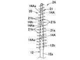
- FIG. 5 (a)is an enlarged front view
- FIG. 5 (b)is an enlarged side view of the cleaning unit.
- Sectional view taken along line VI-VI in Fig. 5 (a)Enlarged front view of the cleaning part of another configuration
- FIG. 6 equivalent view of the cleaning unit of another configurationFIG. 6 equivalent view of the cleaning unit of another configuration
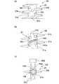
- FIG. 15Ais an explanatory diagram immediately before molding of the soft portion by the second mold
- FIG. 15Bis an explanatory diagram immediately after molding of the soft portion by the second mold.
- Explanatory drawing of the 2nd metallic mold of other compositionExplanatory drawing of the 2nd metallic mold of other composition 18 (a), 18 (b), and 18 (c) are explanatory views showing end shapes of holding pins having other configurations, respectively.
- FIG. 20 (a)is a front view and FIG. 20 (b) is a side view of the cleaning unit of another configuration.
- XXI-XXI line sectional view of Fig. 20 (a) 22 (a)is a front view
- FIG. 22 (b)is a side view
- FIG. 22 (c)is a cross-sectional view taken along line XXII-XXII in FIG. 22 (a).
- FIG. 25A, FIG. 25B, and FIG. 25C of the holding pin having the depression at the tip endare explanatory views showing other modifications, respectively.
- the interdental cleaning tool of this inventionis equipped with the base material part containing a synthetic resin and the soft part containing an elastomer.
- Synthetic resin materials constituting the substrate partinclude polypropylene (PP), polybutylene terephthalate (PBT), polyethylene, polyethylene terephthalate, polycyclohexylene dimethylene terephthalate, saturated polyester resin, polymethyl methacrylate, cellulose propionate, heat Thermoplastic synthetic resin materials such as plastic polyurethane, polyamide, polycarbonate, and ABS (acrylonitrile / butadiene / styrene) can be employed.
- a synthetic resin material which comprises a base material partin order to improve productivity, it is preferable to employ
- polypropylenePP
- polybutylene terephthalatePBT
- polyamidePA
- powdersuch as plate-like or granular glass flakes, mica, talc, etc. to prevent breakage of the cleaning part during insertion between teeth or during interdental cleaning
- a fiber materialsuch as glass fiber, carbon fiber, or aramid fiber can be added.
- thermoplastic elastomerssuch as styrene, olefin, and polyamide, and thermosetting elastomers such as silicon rubber, urethane rubber, fluorine rubber, natural rubber, and synthetic rubber
- a material having compatibility with the synthetic resin material constituting the base portionis preferable.
- the soft portionis preferably made of a polyolefin-based elastomer or a styrene-based elastomer. .
- what added the additivecan also be employ
- the interdental cleaning tool 1includes a cleaning unit 2 for interdental cleaning and a handle unit 3 as a handle when distinguished by its function.
- a base material portion 10 including a synthetic resin and a soft portion 20 including an elastomerare provided.
- This interdental cleaning tool 1is manufactured in the form of an interdental cleaning tool connector 5 in which a plurality of interdental cleaning tools 1 are detachably connected in parallel as shown in FIGS.
- a usercuts off the interdental cleaning tool 1 in order from the one side of the interdental cleaning tool connector 5 and sequentially uses it.
- FIG. 1although the 10 interdental cleaning tools 1 were connected in parallel and the interdental cleaning tool coupling body 5 was comprised, the connection number of the interdental cleaning tools 1 can be set arbitrarily.
- the base material portion 10is made of a thermoplastic synthetic resin, and as shown in FIGS. 1 to 6, a flat and slender plate-like handle base material portion 11 constituting the handle portion 3, and a tip portion of the handle base material portion 11 Are provided with an elongated shaft-shaped core base material portion 12 and a connecting portion 13 for detachably connecting adjacent handle base material portions 11.
- the handle base material portion 11is formed in a flat and slender plate shape.
- a cross-sectional shapemay be a circle or the like as long as it is easy to clean between teeth by picking with a finger.
- Oval shapeelliptical, oval, rounded rectangle, egg shape, oval shape, bowl shape (short-sided curved rectangle, rounded rectangle), etc.
- stick shapeconfigured in teardrop shape, polygonal shape, etc. It can also be formed into a plate shape, a shape bent continuously or stepwise.
- a curved part and a recessed partcan also be provided in a handle base material part for the ease of holding.
- the distal end portion of the handle base material portion 11is configured so as to narrow toward the core base material portion 12 side, and is smoothly connected to the core base material portion 12.
- the handle base material portion 11can be set to any size as long as it is easy to clean between the teeth by picking with a finger.
- the length L1is 10 mm.
- the width W1is set to 4 mm to 8 mm, and the gripping portion thickness t1 is set to 1.0 mm to 2.0 mm.
- the handle base material portion 11is thin, when the base material portion 10 is molded, it is possible to reduce dimensional variations due to the shrinkage of the handle base material portion 11 and to prevent sinking. The poor loading of the base material part 10 to the second molds 40 and 41 for forming the part 20 can be prevented.
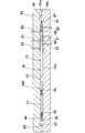
- the core base material portion 12is formed in a substantially straight and elongated shaft shape, and the handle base material portion 11 and the core base material portion 12 are arranged in substantially the same axis, and the core base material portion 12 and the handle base material portion 11 are arranged. Are arranged in the same plane.
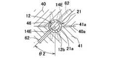
- An exposed portion 12a that is exposed to the outsideis formed on the gripping portion side of the core base material portion 12, and a core body 12b that can be inserted between teeth is formed on the tip side portion of the core base material portion 12 by being covered with an elastomer.
- At least the portion covered by the soft portionis formed in a gently tapered shape that decreases in diameter toward the tip side.
- coveredit does not necessarily need to be linear form, For example, the shape etc. which are bent continuously or in steps can be employ
- the angle ⁇ 1 formed by the taper shape of the outer surface of the core base material portion 12 with respect to the center line of the core base material portion 12is set to 0.2 ° to 1.5 ° in consideration of insertion property between teeth. .
- the diameter of the front end side portion of the core body 12bis set to 0.4 mm to 0.6 mm, the diameter of the base end portion of the core body 12b is set to 0.8 mm to 2.0 mm, and the covering of the soft portion 21 for cleaning is covered.
- the diameter D at the end of the curved surface of the tip portion of the portion 21ais set to 0.5 to 1.2 mm, and the tip side portion of the core body 12b that is at least 5 mm or more from the tip portion of the core body 12b can be reliably inserted between the teeth. It is configured as follows.
- the present inventionis applied to the I-type interdental cleaning tool 1 in which the handle base material portion 11 and the core base material portion 12 are arranged in substantially the same axial shape.
- a so-called L-shaped interdental cleaning tool 1 provided with an angle of 120 ° with respect to the center line of the handle base material portion 11, a handle portion connected to the cleaning portion, and the likeis about 140 ° to 160 °.
- the present inventioncan also be applied to a curved interdental cleaning tool having a smooth curved shape.
- the connecting portion 13is formed integrally with the handle base portion 11 between the adjacent handle base portions 11, and the base end portion side and the tip end side of the handle base portion 11 are formed. One pair is provided at intervals in the longitudinal direction.
- the connecting portion 13is elongated in the length direction of the handle base material portion 11 and is formed in a trapezoidal shape (isosceles trapezoidal shape in FIG. 3) in a front view.
- the number of the connecting portions 13can be arbitrarily set, and it is possible to provide only one. However, when configured as such, the connection strength of the adjacent base material portions 10 is sufficient when the interdental cleaning tool 1 is manufactured.
- the connecting portion 13is broken when the mold is opened, the base material portion 10 is broken, the soft portion 20 cannot be formed, or the connecting portion 13 is bent.
- the base material portion 10cannot be loaded at an appropriate position in the second molding space 42 (see FIG. 14) for forming the soft portion 20, and a molding defect may occur. It is preferable to provide two or more at intervals in the length direction.
- the cross section of the connecting portion 13is formed in a trapezoidal shape or a triangular shape (in FIG. 4, an isosceles trapezoidal shape or an isosceles triangular shape), and as shown by a virtual line in FIG.
- the cleaning tool 1is bent in a direction in which the cleaning tools 1 are overlapped with each other to concentrate the bending force on the boundary portion 13 a, and the arcuate side surface 11 a of the side edge of the handle base material portion 11 contacts the outer surface of the connecting portion 13.
- the interdental cleaning tool 1can be neatly separated without causing a large deformation of the connecting portion 13 in the boundary portion 13a by applying a large force in the direction of pulling away from the boundary portion 13a according to the principle of leverage. It is configured.
- the shape of the connecting portion 13is arbitrary as long as it can be easily and cleanly separated by bending the adjacent interdental cleaning tool 1 in the direction of overlapping each other with the connecting portion 13 as the center. It can be formed in the shape of
- a fiber materialis orientated so that the length direction may turn into the direction along the length direction of the base material part 10.
- the bending strength of the base member 10 and the buckling strength with respect to the axial directioncan be improved, and the core base member 12 can be folded or seated when the interdental cleaning tool 1 is used. Bending can be effectively prevented.
- the amount of holding pins that bite into the core base material portion 12can be reduced and formed.
- the recessed part 14a of the core base material part 12can be made shallow.
- the soft portion 20is formed so as to be integrated with the base material portion 10 using an elastomer material, and includes a cleaning soft portion 21 that is externally mounted on the core base material portion 12. ing.
- an annular insertion restricting portion for restricting insertion between teethis provided at the proximal end portion of the core body 12b, or the handle base portion 11 is entirely or partially covered with an elastomer. It is also possible to provide a stop.
- the insertion restricting portion and the non-slip portioncan be formed independently of the cleaning soft portion 21, but the mold structure becomes complicated, so that the insertion restricting portion and the anti-slip portion are formed so as to continue to the base of the cleaning soft portion 21. Is preferred.
- the wall thickness of the covering portion 21ais too thick, it is necessary to reduce the diameter of the core body 12b covered with the covering portion 21a. Therefore, the rigidity of the cleaning portion 2 at the time of insertion between teeth is greatly reduced.
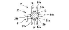
- the cleaning protrusions 21bare formed at intervals in the length direction of the covering portion 21a, and are arranged at intervals in the circumferential direction of the covering portion 21a. More specifically, a pair of cleanings projecting from the covering portion 21a to one side of the mold opening / closing direction in the circumferential direction of the covering portion 21a so as to be molded by the second molds 40 and 41 described later. Projecting portion 21b, a pair of cleaning projecting portions 21b projecting from the covering portion 21a to the other side in the mold opening and closing direction, and projecting from the covering portion 21a to one side along the mating surfaces 40a and 41a.
- cleaning protrusions 21bThere are a total of six types of cleaning protrusions 21b, one cleaning protrusion 21b and one cleaning protrusion 21b protruding from the covering portion 21a to the other side along the mating surfaces 40a and 41a.
- a plurality of types of cleaning protrusions 21b of a kindare formed at intervals in the length direction of the covering portion 21a.
- the cleaning protrusions 21bcan also be formed in an arrangement pattern other than those described above. For example, a set of four cleaning protrusions 21b protruding outward in a cross shape from the covering part 21a. It is also possible to provide an interval in the axial direction.
- the cross-sectional area, length, number, and arrangement interval of the base end portion of the cleaning projection 21bcan be arbitrarily set, but the base end portion of the cleaning projection 21b is considered in consideration of moldability and cleanability.
- the length of the cleaning projection 21bis preferably set to 0.1 mm to 2.5 mm, more preferably set to 0.3 mm to 2.0 mm, and set to 0.5 mm to 1.7 mm. Most preferred.
- the number of the cleaning projections 21bis preferably set to 20 to 100, and the arrangement interval of the cleaning projections 21b is preferably set to 0.5 mm to 1.5 mm.
- adopted as the projection part 21b for cleaningthe flat taper-shaped thing flat in an axial direction is also employable.
- the cross-sectional shape of the cleaning protrusion 21ban arbitrary cross-sectional shape such as an oval shape, a teardrop shape, or a polygon shape can be adopted in addition to a circular shape.
- the core base material portion 12is positioned in the central portion of the second molding space 42 by a plurality of holding pins 50 to 52 provided in the second molds 40 and 41, as will be described later.
- the cleaning part recess 14that penetrates the covering part 21 a and forms the core base part recess 14 a in the core base part 12 is spaced apart in the axial direction of the cleaning part 2.
- At least one set of the two cleaning section recesses 14 of the plurality of sets of cleaning section recesses 14 formed in pairs and paired by the first side portion and the second side portionare arranged in the circumferential direction of the cleaning portion 2.
- the cleaning portion 2is formed with an interval in the axial direction.
- the core base part recess 14ais softened when the relatively high temperature base part 10 immediately after being molded by the first molds 30 and 31 is exposed to the heat of the elastomer filled in the second molds 40 and 41. The tip of the holding pin comes into contact with the softened core base material portion 12.
- the first side portion and the second side portion of the cleaning unit 2are a part of the cleaning unit 2 molded by the second mold 40 and a part of the cleaning unit 2 molded by the second mold 41.
- the cleaning part recessed part 14 which makes a pair by the 1st side part and the 2nd side partis the same cleaning part recessed part 14 counted from the front-end
- the maximum depth d of the core base part recess 14 a from the outer peripheral surface of the core base part 12can be arbitrarily set.
- cleaningis performed.
- a large stress concentrationis generated at the formation position of the core base portion recess 14 a to prevent the core base portion 12 from being broken. Therefore, it is desirable to set it to 0.01 mm or more and 0.085 mm or less, preferably 0.01 mm or more and 0.065 mm.
- the maximum cross-sectional area of the core base material portion 12 at the position corresponding to the core base material portion recess 14ais 55.0 to the cross-sectional area of the core base material portion 12 at the position adjacent to the core base material portion recess 14a. 99.6%, preferably 70.0 to 99.0%, more preferably 80.0 to 97.9%, and most preferably 90.0 to 97.9%.
- production of stress concentrationis reduced and it is comprised so that the bending of the core base material part 12 at the time of insertion between teeth and the cleaning between teeth may be prevented more effectively.
- the front shape of the cleaning portion recess 14is formed in the same shape as the pin tip shape of the holding pin.
- a shape that is long in the spiral direction of the cleaning portion axissuch as a parallelogram, a polygonal shape such as a square or a rectangle, a circular shape, or an oval shape. It is formed in a teardrop shape.
- the plurality of cleaning portion recesses 14 provided in the interdental cleaning tool 1can be formed in the same shape, or can be mixed in any combination of different shapes depending on the distance from the tip of the cleaning portion 2 and the like. You can also
- the cleaning section 2 ⁇ / b> Fhas a front shape that is long in the axial direction of the cleaning section 2 ⁇ / b> F.
- (Rectangular rectangular) cleaning portion recess 14Fis formed.
- the cleaning portion recess 14Fhas a longitudinal direction between the cleaning protrusions 21b adjacent to each other in the circumferential direction by forming the pin tip shape of the holding pin into a bowl shape (a rectangular shape with a short side portion is a curved rectangle or a rounded rectangle). It is formed so as to be in the axial direction of the cleaning unit 2.
- the cleaning portion recess 14A of the cleaning portion 2A shown in FIG. 7may be rectangular, elliptical, or other shapes. is there.
- the plurality of cleaning part recesses 14 provided in the interdental cleaning tool 1can be formed in the same shape as in this example, or have different shapes depending on the distance from the tip of the cleaning part 2 and the like. Can be mixed in any combination.
- the holding pin with a shape longer in the axial direction than the circular holding pincan hold the holding pin with respect to the core base part 12 more strongly, so the vibration of the core base part during the soft part molding Is suppressed, and the depth of the core base portion recess 14Aa is not easily increased.
- produces in the position which provided core base part recessed part 14Aa can be relieve
- the cleaning portion recess 14Gcan be formed by a plate-like holding pin 50G having a shape as shown in FIG.
- the core base material recesses 14Aa, 14Fa, 14Gaare configured to be long in the axial direction of the cleaning parts 2A, 2F, 2G, as in the cleaning parts 2A, 2F, 2G shown in FIGS.
- the cleaning partis inserted between the teeth or when the cleaning part performs interdental cleaning, when a bending force is applied to the cleaning part, a large stress concentration occurs at the position where the core base part recess is formed.
- the opening area of Shinmotozai portion recess0.15 mm 2 ⁇ 0.60 mm 2, preferably in the 0.17 mm 2 ⁇ 0.50 mm 2, more preferably 0. set to 20mm 2 ⁇ 0.40mm 2.
- the core base portion recesses that are long in the axial directionpreferably have a maximum axial length of 0.4 mm to 1.5 mm, more preferably 0.4 mm to 1.3 mm, and even more preferably 0.5 mm to 1 mm. .1mm, and most preferably set to below 0.6 mm ⁇ 1.0 mm, the opening area is preferably 0.15 mm 2 ⁇ 0.6 mm 2, more preferably 0.17 mm 2 ⁇ 0.5 mm 2, Most preferably, it is set to 0.2 mm 2 to 0.4 mm 2 . Further, it is preferable that the total area of the concave portions of the core base material formed on one interdental cleaning tool 1 is set to 0.90 mm 2 to 3.6 mm 2 .
- the opening areas of the core base material recessescan all be set to the same size, but are preferably set so that the core base material recess on the tip side of the core base material portion 12 becomes smaller.
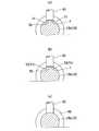
- the bottom surface of the core base part recess 14a of the cleaning part recess 14reflects the shape of the tip support surface of the holding pins 50 to 52 described later, and as shown in FIG. It is constituted by a flat surface in a direction orthogonal to each other. However, it can also be configured in a concave shape in which the central portion is raised as compared with both side portions as viewed from the axial direction of the cleaning portion 2. For example, the center where the shape of the tip support surface is transferred as it is is raised in a state where the holding pin bites into contact with the entire surface of the tip support surface as in the core substrate portion recess 14Ca of the cleaning portion recess 14C shown in FIG.
- the maximum depth of the concave portion 14Cais not the central portion of the concave portion 14Ca, but the side position across the concave portion 14Ca, that is, the side end position in this example.
- the shape of the tip support surface of the holding pinfor example, as shown in the core base part concave part 14Ba of the cleaning part concave part 14B in FIG.
- Various shapesare possible.
- the tip of the holding pinwhich will be described later, does not completely bite into the core substrate, and the center of the tip support surface of the holding pin does not come into contact with the outer peripheral surface of the core substrate even during elastomer molding.
- the core base portion recesses 14Ba and 14Caare separated and formed in two with the central portion interposed therebetween.
- the opening area of Shinmotozai section recess 14ais can be arbitrarily set, preferably 0.08 mm 2 ⁇ 0.35 mm 2, more preferably 0.09mm 2 ⁇ 0.30mm 2, 0.1mm 2 ⁇ 0 Most preferably, it is set to 25 mm 2 .
- the total areais preferably 0.048 mm 2 ⁇ 2.1 mm 2 of Shinmoto material portion recess 14a formed in one interdental cleaning tool 1, more preferably 0.54mm 2 ⁇ 1.8mm 2, 0.60mm more preferably 2 ⁇ 1.5 mm 2, and most preferably set to 0.9mm 2 ⁇ 1.3mm 2.
- the opening areas of the core base part recesses 14acan all be set to substantially the same size, but are preferably set to be smaller as the core base part recesses 14a on the distal end side of the core base part 12 are smaller.
- the opening area of the core base material recess 14arefers to the core exposed in the core base material recess 14a with respect to the plane orthogonal to the center line DL (see FIG. 19) in the depth direction of the core base material recess 14a. It means the area surrounded by the projected figure of the boundary line between the base material part 12 and the cleaning soft part 21.
- the cleaning unit recess 14is configured so that all the cleaning unit recesses 14 paired with the first side and the second side do not overlap in the circumferential direction of the cleaning unit 2. Can be formed with an interval in the axial direction, and only the specific cleaning portion recess 14 that is paired with the first side portion and the second side portion is not overlapped in the circumferential direction of the cleaning portion 2, The cleaning part 2 is formed with an interval in the axial direction, and the remaining cleaning part recesses 14 are provided facing each other with the core base material part 12 interposed therebetween. It can also be shifted in the axial direction.
- the cleaning portion recess 14 on the first sidecan be provided at a substantially central portion of the arrangement interval with respect to the axial direction of the cleaning portion recess 14 on the second side, or the axial direction of the cleaning portion recess 14 on the second side. Although it can also be provided at a position deviated toward the distal end side or the proximal end side of the arrangement interval with respect to, it is preferable to set the interval to 1/4 or more of the maximum axial length of the cleaning portion recess.
- the cleaning portion recess 14 on the first sideis, for example, a position of 1.0 to 2.5 mm, a position of 5.5 to 7.0 mm, and a position of 10.0 to
- the cleaning portion recess 14 on the second sideis formed at least at a position of 11.5 mm, for example, at a position of 1.4 to 3.7 mm from the tip of the cleaning portion 2 and a position of 5.9 to 8.2 mm. And 10.4 to 12.7 mm.
- the number of cleaning recesses 14is preferably 2 or more, and more preferably 3 or more.
- the stress which arises when bending force acts on cleaning part 2 at the time of insertion between teeth or cleaning between teethby constituting the number of sets of cleaning part crevice 14 to 3 sets or more or 4 sets or more.
- the core substrate portion recess 14ais made shallower while securing the holding property of the core substrate portion 12 by the holding pins 50 to 52 as will be described later. In this case, it is possible to effectively prevent the core base material portion 12 from being bent due to concentration of large stress locally.
- the number of the first side cleaning portion recesses 14 and the number of the second side cleaning portion recesses 14are preferably the same, but may be different, for example, the first side cleaning portion recesses.
- the number of 14can be one less than the number of the cleaning part recessed parts 14 of a 2nd side part.
- the arrangement interval of the cleaning portion recesses 14 on the first side portion and the second side portion with respect to the axial direction of the cleaning portion 2can be set to be substantially uniform or narrow toward the front end side of the cleaning portion 2.
- the distal end portion of the cleaning portion 2is a substantially linear and elongated shaft-like structure configured with a smaller diameter than the base end portion, and structurally changes with respect to the force applied by the molding of the cleaning soft portion 21. easy. Therefore, as described above, when the arrangement interval of the cleaning portion recesses 14 is set so as to become narrower toward the tip end side of the cleaning portion 2 or is set to be substantially uniform, when the soft portion 20 is formed, It is easy to prevent the core base material portion 12 from moving from a predetermined position. In particular, it is more preferable that the arrangement interval is substantially uniform because the external force received by the core base material portion 12 at the time of molding the soft portion 20 tends to be uniform.
- the core base portion recesses 14 aare alternately formed on the first side portion and the second side portion of the core base portion 12 at intervals in the axial direction of the core base portion 12. Since the pair of core base material recesses can be prevented from being formed at the same position in the axial direction of the core base material part 12, the cross-sectional area of the core base material part 12 at the position corresponding to the core base material recess 14a Can be increased to prevent the core base material portion 12 from being broken. In addition, since the position of the core base material portion axial direction in which each holding pin applies force to the core base material portion does not overlap, the core base material is compared with the case where the holding pins are in a relationship of overlapping in the circumferential direction.
- the part of the core base material part axial direction in which the part receives forcebecomes longer.
- a core base material partis hold
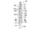
- positioning position of the cleaning part recessed part 14 with respect to the cleaning part 2can also be comprised as follows.
- the cleaning part recesses 14D and 14E and the core base part recesses 14Da and 14Eaare different from the cleaning part recess 14 and the core base part recess 14a only in the formation position with respect to the cleaning part 2, and the core base part.
- the front shape, depth, and opening area of the recesscan be configured similarly to the cleaning portion recess 14 and the core base material recess 14a.
- the center line of the cleaning part recess 14D on the first side and the center line of the cleaning part recess 14D on the second sideare in the radial direction of the cleaning part 2D. It is also possible to form the cleaning portion recess 14D so as to be arranged in parallel with a certain distance.
- the core base portion 12Eis sandwiched and the depth direction of the cleaning portion recess (DL in FIG. ) And the second base mold 40, 41 (see FIG. 14) in the circumferential direction with respect to the mold opening and closing direction of the second mold 40, 41 (see FIG. 14), the first side cleaning portion recess 14E and the core substrate recess 14Ea,
- the cleaning part recessed part 14E and the core base part recessed part 14Ea of 2 side partscan also be arrange
- the cleaning unit recess 14EIn the cleaning unit 2E shown in FIG. 11, only the second set of cleaning unit recesses 14 from the tip of the cleaning unit 2 shown in FIG. 5 is replaced with the cleaning unit recess 14E, and the first and third ones from the tip of the cleaning unit 2E are replaced.
- the individualis composed of the cleaning unit recess 14 arranged so that the depth direction of the cleaning unit recess is the mold opening / closing direction of the second molds 40 and 41, but one or a plurality of sets at arbitrary positions in the cleaning unit 2
- the cleaning portion recess 14can be replaced with a cleaning portion recess 14E.
- the angle ⁇ 2exceeds 60 °, the holding pins 62 (see FIG. 17) provided in the adjacent cleaning soft part molding portions 46 may interfere with each other, and therefore, the angle ⁇ 2 is 60 ° or less, preferably 45 ° or less. It is preferable to set.
- the cleaning portion recesscan be formed with an angle ⁇ 2 on the opposite side across a line segment in the mold opening / closing direction passing through the center of the cleaning portion 2, and a plurality of types of cleaning with different angles ⁇ 2 with respect to the cleaning portion. A partial recess can also be provided.
- the cleaning soft portion 21is formed with a plurality of cleaning protrusions 21b protruding outward.
- the degree of freedom of the layout of the cleaning projection 21bcan be improved. That is, the cleaning portion recess 14E is formed by the holding pin that holds the core base material portion 12 in the center portion of the second forming space 42, and the position of the holding pin 62 is set to the formation position of the cleaning protrusion 21b. Since it can be adjusted in the length direction and the circumferential direction with respect to the second molding space 42 so as not to interfere with each other, the degree of freedom of the layout of the cleaning projections 21b can be improved.
- the handle base material portion 11is configured to be flat, when the handle base material portion 11 is picked by a finger and the space between the molars is cleaned, the cleaning portion 2 is substantially perpendicular to the surface including the handle base material portion 11.
- the cleaning section recess 14 ⁇ / b> Ehas a depth direction that forms an angle ⁇ ⁇ b> 2 with respect to the mold opening / closing direction. Since it is arrange
- the interdental cleaning tool manufacturing methodincludes a base material for manufacturing the base material portion 10 by filling the first molding space 32 of the first mold 30, 31 with a synthetic resin material. After the base part 10 formed by the part molding process and the first molds 30 and 31 is set in the second molding space 42 of the second molds 40 and 41, the second molding space 42 is filled with an elastomer material. And a soft part forming step for forming the soft part 20.
- the first molds 30 and 31correspond to the first mold and the second mold of the first mold, respectively, and the second molds 40 and 41 correspond to the first mold and the second mold of the second mold, respectively. To do.
- the base material portion 10is manufactured by filling the first molding space 32 of the first molds 30 and 31 with a synthetic resin material. More specifically, as the first molds 30 and 31, a plurality of first molding spaces 32 composed of a core base material portion molding portion 32a and a handle base material portion molding portion 32b are formed in parallel, and adjacent handle bases are formed. A pair of connecting portion molding portions 35 communicating with the material portion molding portion 32 b are formed, and a runner 33 is formed on the proximal end side of the plurality of first molding spaces 32, and a plurality of first portions are formed through the gate 34.
- the molding space 32 communicating with the runner 33 and supplying the synthetic resin material to the runner 33the plurality of first molding spaces 32 are filled into the plurality of first molding spaces 32 through the gates 34. 10 will be molded simultaneously. Then, a primary molded product 10 ⁇ / b> A having a plurality of base material portions 10, runner portions 37, gate portions 36, and connecting portions 13 is manufactured.
- the base material part 10can also be shape
- the gate 34is formed on the base end portion of the first forming space 32 opposite to the core base portion forming portion 32a, more preferably, the core base portion forming the first forming space 32 than the connecting portion forming portion 35. If it is the base end side opposite to the portion 32a, it can be formed at an arbitrary position. However, if a side gate is formed as the gate 34 at the base end portion of the first molding space 32, the second die 40 is formed. , 41 when the primary molded product 10A is loaded, it is preferable because the risk of the gate portion 36 of the primary molded product 10A being sandwiched between the second molds 40, 41 can be reduced.
- a hot runnercan be provided in the first mold 30, 31 in place of the runner 33 made of a cold runner.
- the first mold 30, 31is large and the manufacturing cost is high. It is preferable to provide a runner 33 made of a cold runner.
- the plurality of base material parts 10can be connected with stability by the runner part 37, when the primary molded product 10A is transferred to the second molds 40 and 41, the handling property of the primary molded product 10A can be improved. preferable.
- a pin gate having a diameter of 0.1 to 1.5 mmis adopted as the gate 34, for example, in the shape of a cylinder or spindle, a cold runner can be adopted, and the molded product can be made compact by narrowing the interval between the gates 34. It is preferable because it is possible.
- Soft part molding processIn the soft part molding step, as shown in FIGS. 14 and 15, after setting the primary molded product 10 ⁇ / b> A molded by the first molds 30 and 31 in the second molding space 42 of the second molds 40 and 41, The soft material 20 is formed by filling the second molding space 42 with an elastomer material, and the interdental cleaning tool connector 5 in which a plurality of interdental cleaning tools 1 are arranged in parallel is obtained.
- the second molds 40 and 41include a plurality of base material parts of the primary molded product 10A molded by the first molds 30 and 31.
- a plurality of second molding spaces 42are formed at positions corresponding to 10, and fitting spaces 43, 44, 45 that fit the runner portion 37, the plurality of gate portions 36, and the connecting portion 13 of the primary molded product 10 ⁇ / b> A are provided. Is formed.
- a cleaning soft part molding part 46 surrounding the core base material part 12is formed as a second molding space 42.
- Gates 47are formed on the mating surfaces 40a and 41a with the second molds 40 and 41 on the front end side of the cleaning soft portion molding portion 46, respectively.
- the gate 47is connected to a common runner 48 formed in the second molds 40, 41, and the elastomer material is supplied from the common runner 48 to the plurality of second molding spaces 42 through the plurality of gates 47.
- the diameter of the gate 47is preferably set to 0.1 mm or more and 1.0 mm or less.
- the second molds 40 and 41include a distal end side holding pin 50, a middle portion holding pin 51, and a proximal end side corresponding to the distal end side portion, the middle portion, and the proximal end portion of the cleaning soft portion molding portion 46, respectively.
- a holding pin 52is provided.
- the three sets of holding pins 50 to 52 paired with the second mold 40 and the second mold 41do not overlap in the circumferential direction of the cleaning soft part forming part 46, so that the cleaning soft part forming part 46 is installed in each of the second molds (40, 41) with an interval in the axial direction.
- the holding pin of the second mold 41 that forms a pair with the holding pin of the second mold 40means the same holding pin as counted from the tip of the cleaning soft part molding portion 46.
- the cleaning soft part moldingis performed so that only the specific holding pin of the second mold 40 and the specific holding pin of the second mold 41 paired therewith do not overlap in the circumferential direction of the cleaning soft part molding part 46. It can also install in each 2nd metal mold
- die (40, 41)at intervals in the axial direction of the part 46.
- FIG.since a large bending force is likely to act on the portion of the cleaning portion 2 that is 6 mm from the distal end portion during cleaning between molars, only the second holding pin 51 that holds the vicinity of the position is used as the soft soft portion for cleaning. It is preferable to displace the molding portion 46 in the axial direction.
- the remaining pair of holding pinsare provided facing each other with the core base material portion 12 interposed therebetween, or are shifted in the axial direction of the core base material portion 12 within a range equal to or smaller than the diameter of the holding pin. It will be.
- the three sets of holding pins 50 to 52 of the second molds 40 and 41are substantially perpendicular to the mating surfaces 40a and 41a of the second molds 40 and 41, in other words, in the mold opening / closing direction of the second molds 40 and 41.
- the core base material portion 12 of the base material portion 10is provided so as to be movable.
- the tip portions of these three sets of holding pins 50 to 52are placed in the cleaning soft portion forming portion 46.
- the holding pinmay be fixed to the mold in a state of protruding in advance from the cleaning soft part molding portion of the second mold.
- the cross-sectional areas of the cross-sections orthogonal to the axial direction of the tip portions of the holding pins 50 to 52are substantially the same as each other, or the holding pins 50 positioned closest to the tip are cross-sectional areas of the tip portions of the holding pins at other positions. Small compared to the cross-sectional area.
- the intermediate portion holding pin 51 and the proximal end side holding pin 52are substantially the same or configured so that the intermediate portion holding pin 51 is larger than the proximal end side holding pin 52. That is, since the passage area of the distal end portion of the cleaning soft portion molding portion 46 is reduced, the flow resistance of the elastomer material is set as small as possible by reducing the cross-sectional area of the distal end holding pin 50 as much as possible.
- the cross-sectional areas of the holding pins 50 to 52can be set to be the same. Further, a plurality of intermediate portion holding pins 51 can be provided at intervals in the axial direction.
- the holding pins 50 to 52 of the second mold 41are configured as follows. However, the holding pins 50 to 52 of the second mold 40 are the same except that the holding pins 50 to 52 of the second mold 40 are shifted from the holding pins 50 to 52 of the second mold 41 toward the base end side. Since the configuration is the same as that of the second mold 41, only the holding pins 50 to 52 of the second mold 41 will be described.
- the distal end side holding pin 50 of the second mold 41is provided within a range of 3 mm from the distal end portion 46a of the cleaning soft portion molding portion 46 toward the proximal end side, and its cross-sectional area is 0.03 mm 2 to 0. It is set to 3 mm 2 .
- the intermediate portion holding pin 51is provided within a range of ⁇ 10% of the length of the cleaning portion 2 in the axial direction around the middle point between the distal end side holding pin 50 and the proximal end side holding pin 52, and its cross-sectional area. Is set to 0.12 mm 2 to 1.2 mm 2 .
- the proximal end holding pin 52is The cleaning soft portion molding portion 46 is provided within a range of 6 mm from the proximal end portion toward the distal end side, and its cross-sectional area is set to 0.1 mm 2 to 1.1 mm 2 . By setting these, it is expected that not only the core base material portion 12 is fixed during molding, but also the influence of Karman vortices generated during molding on the molded body is prevented.
- the core base material portion 12is softened by the heat of the elastomer material, and the core base material portion is connected to the first side portion and the second side portion of the core base material portion 12 by the tip portions of the holding pins 50 to 52. Since the core base portion recesses 14a are alternately formed at intervals in the 12 axial directions, it is possible to prevent a pair of core base portion recesses from being formed at the same position in the axial direction of the core base portion 12. The cross-sectional area of the core base material portion 12 at the position corresponding to the core base material recess 14a can be increased to prevent the core base material portion 12 from being broken.
- the core base materialis compared with the case where the holding pins are in a relationship of overlapping in the circumferential direction.
- the part of the core base material part axial direction in which the part receives forcebecomes longer.
- a core base material partis hold
- the core baseis stable. It becomes possible to hold it with good performance.
- the cross-sectional area of the holding pin 50is set smaller than the cross-sectional area of the holding pins 51 and 52, filling of the elastomer material from the distal end portion of the cleaning soft portion molding portion 46 to the proximal end side is performed. By preventing the injection pressure from being disturbed as much as possible by 50 to 52, even if the injection pressure varies somewhat, the core base material portion 12 is prevented from being bent, and the cleaning soft portion 21 containing the elastomer material is accurately formed.
- the holding pins 50 to 52are fixed to the mold in a state where the holding pins 50 to 52 protrude in advance from the cleaning soft part molding portion of the second mold, and the second molds 40 and 41 are closed.
- a manufacturing method for holding the core substrate portioncan also be employed.
- the runner portion 37 and the gate portion 36 including the synthetic resinare removed, and the runner portion 55 including the elastomer formed by the runner 48 and the gate 47 and The interdental cleaning tool 1 is obtained by removing the gate portion 56.
- the cross-sectional shape of the tip of the holding pins 50 to 52is circular.
- the length of the cleaning soft part molding part 46is reduced. It can be formed into a long oval shape, teardrop shape, rectangle or bowl shape (rectangular shape with short sides and rounded corners), and any combination of holding pins with different cross-sectional shapes Can also be used.
- the cross-sectional shapeis a shape that is long in the length direction of the second molding space 42, in this example, a bowl shape (a rectangular shape with a short side portion curved). , A rounded rectangular) holding pin 50F.
- the length dimension of the holding pin along the length direction of the second molding spaceis set to 0.4 mm or more and 1.5 mm or less, more preferably 0.5 mm to 1.0 mm.
- the cross-sectional area of the cross section perpendicular to)is set to 0.2 mm 2 or more and 0.6 mm 2 or less.
- the front end surface of the holding pins 50 to 52 that comes into contact with the core base material portion 12is a flat surface orthogonal to the axial direction of the holding pins 50 to 52 as shown in FIG.
- itis configured by an arcuate surface along the outer peripheral surface of the core base material portion 12, or is connected in an isosceles triangular shape like the holding pin 61 shown in FIG. 18 (c).
- the contact area between the core base material portion 12 and the holding pins 60 and 61is set large, This is preferable because the depth can be set shallow, the core base material portion 12 can be held in the center of the second molding space 42 with high accuracy, and the holdability of the core base material portion 12 can be improved.
- holding pins having different tip end surface shapescan be used in any combination.
- the tip support surface 7has a concave shape in which the central portion 70 is recessed as compared to the side portions 71, 71 when viewed from the axial direction of the cleaning soft portion forming portion 46, and at least the side portion 71 has a core.
- the core base material portionis formed by the at least both side portions 71 in a shape having a region where the holding pin 61 comes into contact with the outer surface of the base material portion 12 from the beginning. 12 is held in a stable posture by the force dispersed from the beginning of the holding pin contact, so that the holding pin 61 can hold the core substrate part 12 without biting into the core substrate part 12, and the formed core substrate part recess Shallow depth of 14a It can be.
- both side portions 71first come into contact with the outer surface of the core base material portion 12, and the core base material portion has a stable posture in at least two positions as compared with a conventional flat pin. 12 is held. And when the core base material part 12 is not cooled down and is in a soft state or due to its own weight, etc., the holding pin 61 usually bites into the core base material part 12, but since it is supported at least in two positions from the beginning, its force is It is dispersed and does not penetrate deeply from the beginning like a conventional flat pin, but receives the force on the entire tip support surface 7 and the biting depth is suppressed.
- the core base material portion 12is thermally expanded or softened by being exposed to a high temperature elastomer, and the core base material portion 12 exerts a force during the filling of the elastomer.
- the holding pin 61tries to further bite into the core base material portion 12 in response to the vibration.
- the core base material portion 12is held in a stable posture at two positions from the beginning, and the vibration is also effective. Therefore, the final bite can be suppressed shallowly.
- the shape of the tip support surface 7 of the holding pin 61is a shape recessed in a substantially V shape when viewed from the axial direction of the cleaning soft portion molding portion 46, but is not limited thereto, and is not limited to this.
- the shapehas a region where the holding pin 61 comes into contact with the outer surface of the core base material portion 12 from the beginning, as seen from the axial direction of the cleaning soft portion molding portion 46, for example, as shown in FIG.
- abut to the core base material part 12 from the beginningdo not necessarily need to include the side edge of the front-end
- the central portion 70is initially configured to maintain a gap with the outer surface without contacting the outer surface of the core base material portion 12.
- the inventionis not limited to this, and any shape is acceptable as long as at least both side portions 71 sandwiching the central portion 70 are in contact with each other from the beginning, and the shape in which the central portion 70 is also in contact simultaneously, that is, as shown in FIG.
- a shape that is substantially U-shaped and in which the entire tip support surface 7 comes into contact with the core base material portion 12 from the beginningis also included in the present invention.
- the arrangement positions of the holding pins 50 to 52 with respect to the second molds 40 and 41can also be configured as follows. Like the holding pins 62 of the second molds 40 and 41 shown in FIG. 17, the axial direction is circumferential with respect to the mold opening / closing direction of the second molds 40 and 41, with the core base material 12 being sandwiched therebetween.
- the holding pin 62 of the first mold 40 and the holding pin 62 of the second mold 41can be arranged so as to form an angle ⁇ 2.
- the second set of holding pins from the tip of the cleaning soft part molding part 46is replaced with the holding pin 62, and the first and third parts from the tip of the cleaning soft part molding part 46 are in the axial direction.
- the angle ⁇ 2is preferably set to 60 ° or less, preferably 45 ° or less.
- the second molds 40 and 41may be provided with a plurality of types of holding pins 62 having different angles ⁇ 2.
- the cleaning soft portion 21is formed with a plurality of cleaning protrusions 21b protruding outward.
- the degree of freedom of the layout of the projections 21b for usecan be improved. That is, the holding pin 62 is formed by the holding pin 62 that holds the core base material portion 12 at the central portion of the cleaning soft portion forming portion 46, and the position of the holding pin 62 is formed by the cleaning protrusion 21b. Since the cleaning soft portion molding portion 46 can be adjusted in the length direction and the circumferential direction so as not to interfere with the position, the degree of freedom of the layout of the cleaning projection 21b can be improved.
- the handle base material portion 11is configured to be flat, when the handle base material portion 11 is picked by a finger and the space between the molars is cleaned, the cleaning portion 2 is substantially perpendicular to the surface including the handle base material portion 11.
- the holding base 62is arranged so as to form an angle ⁇ 2 with respect to the opening and closing direction of the die, but the core substrate formed by the holding pin 62 is curved in the (die opening and closing direction) plane. It is possible to effectively prevent the core base material portion 12 from being broken at the time of use starting from the portion recess 14Ea.
- Examples 1 to 19 and Comparative Examples 1 to 9 that have been subjected to finite element analysiswill be described.
- the core base material portion 12a rod-shaped core base material portion having a diameter of 0.65 mm and a length of 10 mm is used as a common configuration, and a core base material concave portion having a predetermined depth is formed on the first side portion and the second side portion. Formed.
- the first sidewas placed in the lower position and tested. Accordingly, the “lower surface” coincides with the first side portion, and the “upper surface” coincides with the second side portion.
- the “planar shape of the recess”means a shape obtained when the core substrate recess is observed from above.
- Diameter or width of recessmeans the diameter when the planar shape of the recess of the core base material is circular, and when the shape is other than a circle, it goes directly to the central axis (CL in FIG. 19) of the core base material. It means the maximum length between the intersections of the surface to be performed (VS in FIG. 19) and the core substrate portion recess end.
- the length of the concave portionmeans the intersection (T, B in FIG. 19) of the surface (BS in FIG. 19) including the central axis (CL in FIG. 19) of the core base portion and the end of the core base portion concave portion. ) (UL in FIG. 19).
- the “depth of the concave portion”means “the maximum depth of the concave portion of the core base material portion”.
- Example 1a core base part recess having a circular shape with a diameter of 0.4 mm and a depth of 0.07 mm is formed on the first side part of the core base part with a thickness of 6.0 mm from the tip of the core base part.
- the center base portionis formed at a center, and a core base portion recess having a circular shape with a diameter of 0.4 mm and a depth of 0.07 mm is formed on the second side portion of the core base portion.
- the centerwas formed at a position of 6.8 mm from the part. That is, the interval in the axial direction (UL direction in FIG.
- Example 2the first side part formed by positioning the core base part concave portion with the center located at a position of 6.0 mm from the tip part of the core base part on the lower surface, the first side part and the second side
- the same configuration as in Example 1was set, except that the axial distance between the core base material portions of the core base material recesses was set to three times the axial maximum length of the core base material recesses.
- Example 3as a core base material recess, both ends are formed into a semicircle with a diameter of 0.4 mm, and the length of the recess is set to 1.14 mm.
- the structurewas the same as in Example 1 except that a rounded rectangle was formed.
- Example 4as a core base material recess, both ends are formed in a semicircular shape having a diameter of 0.4 mm, and the length of the recess is set to 1.14 mm.
- the configurationwas the same as in Example 2 except that a rounded rectangular shape was formed.
- Example 5as the core base material recess, the width of the recess was set to 0.4 mm, and the length of the recess was set to 1.2 mm, except that a rectangular core base material recess was formed.
- the configurationwas the same as in Example 1.
- Example 6as the core base material recess, the width of the recess was set to 0.4 mm, and the length of the recess was set to 1.2 mm, except that a rectangular core base material recess was formed.
- the configurationwas the same as in Example 2.
- Example 7except that the axial distance of the core base material portion of the core base material recess of the first side portion and the second side portion was set to 1 time the axial maximum length of the core base material recess, The configuration was the same as in Example 3.
- Example 9except that the axial distance between the core base part of the core base part recesses of the first side part and the second side part was set to one time the axial maximum length of the core base part recess,
- the configurationwas the same as in Example 5.
- Example 10the axial distance between the core base material portions of the core base material recesses of the first side portion and the second side portion is set to one time the maximum axial length of the core base material recesses.
- the configurationwas the same as in Example 1 except that the depth was set to 0.02 mm.
- Example 11was configured in the same manner as Example 10 except that the depth of the recess was set to 0.05 mm.
- Example 12was configured in the same manner as Example 8 except that the depth of the recess was set to 0.02 mm.
- Example 13except that the axial distance between the core base part of the core base part recesses of the first side part and the second side part was set to one time the axial maximum length of the core base part recess, The configuration was the same as in Example 12.
- Example 14was configured in the same manner as Example 12 except that the depth of the recess was set to 0.05 mm.
- Example 15except that the axial distance between the core base part of the core base part recesses of the first side part and the second side part was set to one time the axial maximum length of the core base part recess, The configuration was the same as in Example 14.
- Example 16a rectangular core base material recess was formed in which the width of the recess was set to 0.4 mm, the length of the recess was set to 1.14 mm, and the depth of the recess was set to 0.02 mm. And the space
- Example 17was configured in the same manner as in Example 16 except that the axial distance between the core base material portions of the core base material recesses on the first side portion and the second side portion was set to 1 time.
- Example 18was configured in the same manner as in Example 16 except that the depth of the core base material recess was set to 0.05 mm.
- Example 19was configured in the same manner as Example 17 except that the depth of the core base material recess was set to 0.05 mm.
- the core base part recess on the second side part of the core base partis formed at a position 6.0 mm from the tip of the core base part, and the core bases of the first side part and the second side part are formed.
- the configurationwas the same as in Example 1 except that the material portion recess was formed at the same position.
- the core base part recess on the second side part of the core base partis formed at a position of 6.0 mm from the tip part of the core base part, and the core bases of the first side part and the second side part are formed.
- the configurationwas the same as in Example 1 except that the axial distance between the core base material portions of the material portion recesses was overlapped by a length that was 1 ⁇ 2 the diameter of the maximum length in the axial direction of the core base material recesses.
- the core base part recess on the second side part of the core base partis formed at a position 6.0 mm from the tip part of the core base part, and the core bases of the first side part and the second side part are formed.
- the configurationwas the same as in Example 1 except that the material portion recess was formed at a position circumscribing the axial direction of the core base material portion.
- Comparative Examples 4 to 6both ends were formed in a semicircular shape with a diameter of 0.4 mm as a core base part recess on the first side and the second side, and the length of the recess was set to 1.14 mm.
- Comparative examples 1 to 3were configured in the same manner except that a core-shaped concave portion with a bowl shape (short-sided curved rectangle, rounded rectangular shape) was formed.
- Comparative Examples 7 to 9as the core base part recesses on the first side part and the second side part of the core base part, the width of the recess is set to 0.4 mm and the length of the recess is set to 1.2 mm. Comparative Example 1 to 3 were configured in the same manner except that the rectangular core base part recess was formed. In addition, since the planar shape of the concave portion in Comparative Examples 1 to 3 is circular, the “diameter of the concave portion” is defined as “the width of the concave portion”.
- the core bases of the first side part and the second side parthave the same or different depths of the concave portions of the core base part. If the material part recesses are arranged in the axial direction so as not to overlap the circumferential direction of the cleaning part, the stress value becomes small, and even when the core base material part is bent during insertion between molars, it is difficult to break. I understand that. Further, it can be seen from Examples 1 to 19 and Comparative Examples 1 to 3 that the stress value tends to decrease as the distance between the upper and lower core base material recesses in the axial direction increases. Further, it can be seen that the stress value is smaller in the shape of the concave portion of the core base material portion in the shape of a bowl (a rectangular shape with a short side portion, a rounded rectangle) or a rectangle than a circle.
Landscapes
- Engineering & Computer Science (AREA)
- Manufacturing & Machinery (AREA)
- Mechanical Engineering (AREA)
- Health & Medical Sciences (AREA)
- Life Sciences & Earth Sciences (AREA)
- Epidemiology (AREA)
- Dentistry (AREA)
- Animal Behavior & Ethology (AREA)
- General Health & Medical Sciences (AREA)
- Public Health (AREA)
- Veterinary Medicine (AREA)
- Moulds For Moulding Plastics Or The Like (AREA)
- Brushes (AREA)
Abstract
Description
Translated fromJapanese本発明は、エラストマで被覆した清掃部を有する歯間清掃具に関するものである。The present invention relates to an interdental cleaning tool having a cleaning portion covered with an elastomer.
歯間清掃具として、合成樹脂を含む基材部と、エラストマを含む軟質部とを備え、前記基材部は、ハンドル基材部と、前記ハンドル基材部の先端部に設けた細長い軸状の芯基材部とを有し、前記軟質部は、前記芯基材部を被覆する清掃用軟質部を少なくとも有し、前記ハンドル基材部で持ち手としてのハンドル部を構成し、前記芯基材部と清掃用軟質部とで歯間清掃用の清掃部を構成したものが実用化されている(例えば、特許文献1~5参照。)。As an interdental cleaning tool, a base part including a synthetic resin and a soft part including an elastomer are provided, and the base part includes a handle base part and an elongated shaft-like shape provided at a tip part of the handle base part A core base part, and the soft part has at least a soft cleaning part for covering the core base part, and the handle base part constitutes a handle part as a handle, and the core A structure in which a cleaning part for interdental cleaning is composed of a base material part and a soft cleaning part has been put into practical use (see, for example,
前記歯間清掃具の製造方法としては、第1金型の第1成形空間に合成樹脂材料を充填して基材部を製作し、第1金型にて成形した基材部を第2金型の第2成形空間にセットして、第2金型の第1型と第2型とに、第2成形空間の長さ方向(芯基材部の軸方向)に間隔をあけて対面状に設けた複数組の保持ピンで、芯基材部を第2成形空間の中央部に位置決め保持した状態で、第2成形空間にエラストマ材料を充填して軟質部を成形することで、歯間清掃具を得るようになした製造方法が広く採用されている。また、通常は、複数個の歯間清掃具を同時成形できるように、第1金型に複数個の第1成形空間を設けるとともに、第2金型に第1成形空間と同数の第2成形空間を設け、歯間清掃具を製作する際には、複数個の第1成形空間に対して合成樹脂材料を供給して、複数個の基材部がランナ部で連結されるように同時に製作し、ランナ部にて連結された複数個の基材部からなる一次成形品を第2金型の第2成形空間にセットして、複数個の第2成形空間にエラストマ材料を充填することで、複数個の歯間清掃具を同時成形するように構成している。As a method for manufacturing the interdental cleaning tool, a base material part is manufactured by filling a first molding space of a first mold with a synthetic resin material, and the base part molded by the first mold is a second metal. Set in the second molding space of the mold, facing the first mold and the second mold of the second mold with an interval in the length direction of the second molding space (axial direction of the core base material) With a plurality of sets of holding pins provided at the center, the core base material portion is positioned and held in the center portion of the second molding space, and the soft material is molded by filling the second molding space with an elastomer material. A manufacturing method for obtaining a cleaning tool is widely adopted. In addition, normally, a plurality of first molding spaces are provided in the first mold so that a plurality of interdental cleaning tools can be simultaneously molded, and the second molding having the same number as the first molding spaces is provided in the second mold. When manufacturing the interdental cleaning tool by providing a space, the synthetic resin material is supplied to the plurality of first molding spaces and manufactured simultaneously so that the plurality of substrate parts are connected by the runner part. Then, by setting a primary molded product composed of a plurality of base material parts connected by a runner part in the second molding space of the second mold, and filling the plurality of second molding spaces with an elastomer material. A plurality of interdental cleaning tools are formed at the same time.
ところで、清掃部を歯間に対して挿入するときには、軸方向に対して大きな圧縮の力が作用する。また、臼歯間、特に大臼歯間を清掃する際には、口腔内に対して前後方向に挿入した歯間清掃具の先端部から中間部にかけて、60°~90°湾曲させながら臼歯間に挿入する必要があり、また歯間清掃時には、湾曲させた状態で、臼歯間の隙間に対して清掃部を出し入れする必要があることから、清掃部に対して大きな曲げ荷重が作用する。このため、基材部を合成樹脂材料で構成した歯間清掃具では、歯間への挿入時や歯間清掃時における、清掃部の折れ対策が重要な課題の1つになっている。By the way, when the cleaning part is inserted between the teeth, a large compression force acts in the axial direction. Also, when cleaning between molars, especially between molars, insert between the molars while curving 60 ° to 90 ° from the tip to the middle of the interdental cleaning tool inserted in the front-rear direction into the oral cavity. When cleaning between teeth, it is necessary to put in and out the cleaning portion with respect to the gap between the molar teeth in a curved state, so that a large bending load acts on the cleaning portion. For this reason, in the interdental cleaning tool in which the base material portion is made of a synthetic resin material, countermeasures against breakage of the cleaning portion during insertion between the teeth or during interdental cleaning are one of the important issues.
清掃部の折れ対策として、基材部を構成する合成樹脂材料にガラス繊維を添加したものも提案されている。しかし、細長い清掃部の折れを防止できる十分な量のガラス繊維を添加すると、芯基材部の芯軸方向における強度剛性が高くなって、歯間部への挿入性は向上するが、芯基材部が撓み難くなることから挿入するためにより強い力が必要となり、臼歯間の清掃時に、芯基材部に大きな曲げ荷重が作用し易く、長さ方向の途中部で芯基材部が折れてしまうという問題があった。As a countermeasure against breakage in the cleaning part, a synthetic resin material constituting the base part with glass fiber added has been proposed. However, when a sufficient amount of glass fiber is added to prevent the elongate cleaning part from being broken, the strength rigidity in the core axis direction of the core base material part is increased, and the insertability into the interdental part is improved. Since the material part becomes difficult to bend, a stronger force is required for insertion, and a large bending load tends to act on the core base material part during cleaning between molars, and the core base material part breaks in the middle in the length direction. There was a problem that.
一方、芯基材部として、スーパーエンジニアリングプラスチック、例えばポリエーテルサルフォンを採用すると、芯基材部が撓み易くなって、清掃部の折れを抑制できるが、スーパーエンジニアリングプラスチックの成形には、高い射出温度が必須となり、射出成型後における冷却時間が長くなることから、歯間清掃具の生産性が低下し、また材料コストも高いことからトータルの製造コストがかなり高くなるという問題があった。On the other hand, if super engineering plastic, for example, polyethersulfone, is used as the core base material part, the core base material part is easy to bend and can prevent the cleaning part from being bent. Since the temperature is essential and the cooling time after the injection molding is long, the productivity of the interdental cleaning tool is lowered, and the material cost is high, so that the total manufacturing cost is considerably increased.
本発明者は、芯基材部が折れる原因として、清掃用軟質部の成形時に第2金型において芯基材部を位置決めするための保持ピンと芯基材部の接触する位置に凹部が形成され易い点、この凹部の位置において芯基材部の横断面積が小さくなり、芯基材部に曲げの力が作用することによって生じる応力が高くなる点、高い応力が集中する部位に凹部が存在することで構造変化が生じやすくなり、歯間への挿入時や歯間清掃時に作用する曲げの力によって、凹部が形成される軸位置付近で芯基材部が折れる点、を見出した。As a cause of the breakage of the core base material portion, the inventor forms a concave portion at a position where the holding pin for positioning the core base material portion and the core base material portion in the second mold come into contact with the second mold during molding. The easy point, the cross-sectional area of the core base material portion is reduced at the position of the concave portion, the stress generated by the bending force acting on the core base material portion is increased, and there is a concave portion in a portion where high stress is concentrated. As a result, it was found that the structural change is likely to occur, and the core base material part breaks in the vicinity of the axial position where the recess is formed due to the bending force acting during insertion between teeth or during interdental cleaning.
保持ピンにより芯基材部に凹部が形成されるメカニズムは明確ではないが、次のようなメカニズムにより凹部が形成されるものと推定できる。即ち、第1金型にて成形した基材部は、冷却後に第2金型にセットされるが、成形時間を短縮するため、比較的高温な状態で第2金型にセットされ、しかも第2金型にセットした基材部は、第2成形空間に充填した高温のエラストマに曝される関係上、清掃用軟質部の成形途中で軟化する。また、第2金型では、複数組の保持ピンを予め設定した突出長さだけ第2成形空間内へ突出させて、芯基材部を第2成形空間の中央部に位置決めすることになるが、成形時間を短縮することによる成形収縮差によって芯基材部の成形寸法のバラツキが発生したり、高温のエラストマに曝されることにより芯基材部の熱膨張や、エラストマの充填時における芯基材部の振動などにより、保持ピンの先端部が芯基材部に食い込んで、芯基材部に凹部が形成されるものと推定できる。The mechanism by which the concave portion is formed in the core base material portion by the holding pin is not clear, but it can be estimated that the concave portion is formed by the following mechanism. That is, the base material part molded with the first mold is set in the second mold after cooling, but in order to shorten the molding time, it is set in the second mold at a relatively high temperature, and The base material set in the two molds is softened during the molding of the cleaning soft portion because it is exposed to the high temperature elastomer filled in the second molding space. Further, in the second mold, a plurality of sets of holding pins are projected into the second molding space by a preset projection length, and the core base material portion is positioned at the center of the second molding space. Variations in the molding dimensions of the core base material due to molding shrinkage differences due to shortening of the molding time, or thermal expansion of the core base material due to exposure to a high temperature elastomer, and the core during elastomer filling It can be presumed that the tip portion of the holding pin bites into the core base material portion due to vibration of the base material portion, and a recess is formed in the core base material portion.
また、ハンドル部の中心線と芯基材部の軸線とを同軸状に配置した、所謂I型の歯間清掃具において、指で摘まみやすいようにするため、ハンドル部を扁平な形状に構成する場合には、通常、ハンドル部は第1金型及び第2金型の型開閉方向に対して扁平に構成し、また保持ピンは、金型構造をできるだけ簡単にするため、保持ピンの軸方向が第2金型の型開閉方向に配置されるように設けている。このため、I型の歯間清掃具では、ハンドル部を摘まんで臼歯間を清掃するときに、保持ピンにより形成される芯基材部の凹部が、湾曲する芯基材部の外周側と内周側とに配置され、内外周両側の凹部付近に大きな応力の集中が発生することで、芯基材部が折れ易くなることを見出した。Further, in the so-called I-type interdental cleaning tool in which the center line of the handle part and the axis of the core base material part are arranged coaxially, the handle part is configured in a flat shape so that it can be easily picked up with fingers. In some cases, the handle portion is usually configured to be flat with respect to the mold opening and closing directions of the first mold and the second mold, and the holding pins are arranged in the axial direction of the holding pins in order to make the mold structure as simple as possible. Are arranged in the mold opening / closing direction of the second mold. For this reason, in the I-type interdental cleaning tool, when the handle portion is picked and the interdental teeth are cleaned, the concave portion of the core base material portion formed by the holding pins is formed on the outer peripheral side and the inner side of the curved core base material portion. It has been found that the core base material portion is easily broken by the large stress concentration occurring near the concave portions on both the inner and outer peripheral sides.
本発明の目的は、簡単な構成で、歯間清掃具の生産性を低下させることなく、歯間への挿入時や歯間清掃時における芯基材部の折れの発生を効果的に防止し得る、歯間清掃具を提供することである。The object of the present invention is to effectively prevent the occurrence of the breakage of the core base material portion during insertion and interdental cleaning without reducing the productivity of the interdental cleaning tool with a simple configuration. It is to provide an interdental cleaning tool.
本発明は、以下の発明を包含する。
(歯間清掃具)
(1)合成樹脂を含む基材部と、前記基材部の少なくとも一部を被覆するエラストマを含む軟質部とを備え、前記基材部は、ハンドル基材部と、前記ハンドル基材部の先端部に連設した細長い軸状の芯基材部とを有し、前記軟質部は、前記芯基材部を被覆する清掃用軟質部を少なくとも有し、前記ハンドル基材部で持ち手としてのハンドル部を構成し、前記芯基材部と清掃用軟質部とで歯間清掃用の清掃部を構成した歯間清掃具であって、前記清掃部の第1側部と第2側部のそれぞれに、前記清掃用軟質部を貫通して、前記芯基材部に芯基材部凹部を形成する清掃部凹部を、前記清掃部の軸方向に間隔をあけて2個以上形成し、第1側部と第2側部とで対をなす複数組の清掃部凹部のうちの少なくとも1組の2個の清掃部凹部を、前記清掃部の周方向に重複しないように、前記清掃部の軸方向に間隔をあけて形成した、歯間清掃具。The present invention includes the following inventions.
(Interdental cleaning tool)
(1) A base material portion including a synthetic resin and a soft portion including an elastomer covering at least a part of the base material portion, wherein the base material portion includes a handle base material portion and a handle base material portion. An elongated shaft-shaped core base material portion connected to the tip portion, the soft portion has at least a cleaning soft portion covering the core base material portion, and the handle base material portion serves as a handle. An interdental cleaning tool comprising an interdental cleaning portion composed of the core base material portion and the cleaning soft portion, the first side portion and the second side portion of the cleaning portion. Each of the cleaning soft part, penetrating the cleaning soft part, forming a core base part recess in the core base part, forming two or more cleaning part recesses in the axial direction of the cleaning part, At least one set of two cleaning section recesses of the plurality of cleaning section recesses paired with the first side portion and the second side portion is provided with the cleaning section. So as not to overlap in the circumferential direction, it was formed at intervals in the axial direction of the cleaning unit, interdental cleaner.
なお、清掃部の第1側部と第2側部とは、清掃部を成形する第2金型における、一方の金型にて成形される清掃部の外周面の片側半部と、他方の金型にて成形される清掃部の外周面の残りの片側半部を意味する。また、前記清掃部の軸方向に間隔をあけて形成した前記清掃部凹部以外の清掃部凹部は、芯基材部を挟んで対面状に形成することができる。加えて、本明細書において、第1側部の清掃部凹部と対をなす第2側部の清掃部凹部とは、清掃部の先端から数えて同じ番目の清掃部凹部を意味する。なお、清掃部の軸方向に対する間隔とは、清掃部軸方向における2つの凹部の端を結んだ最短距離を言う。具体的には、以下の手順で求める。まず、ULおよび芯基材部の中心線(図19のCL)を含む平面(図19のBS)を設定する。次に、第1側部と第2側部の各々の凹部と前記BSとの交点(図19のB、T)からCLに対して垂線を降ろし、垂線とCLとの交点を求める。さらに、第1側部から求めた前記垂線とCLの交点を求める。得られた第1側部の2つのCL上の点から1つ選択し第2側部の2つのCL上の点から1つ選択して両者のCL上の長さを求める。組合せが4つ存在するので、前記で求められる長さは4つ得られる。この得られた4つの長さのうち最短の長さを周方向に重複しない2つの凹部の「清掃部の軸方向に対する間隔」とする。本願において、凹部は、清掃部凹部と芯基材部凹部の2つ存在するが、前記の「凹部」を求めたい方の凹部に置換することにより求められる。In addition, the 1st side part and 2nd side part of a cleaning part are one side half part of the outer peripheral surface of the cleaning part shape | molded by one metal mold | die in the 2nd metal mold | die which forms a cleaning part, and the other side. It means the remaining half on one side of the outer peripheral surface of the cleaning part formed by a mold. Moreover, cleaning part recessed parts other than the said cleaning part recessed part formed with the space | interval in the axial direction of the said cleaning part can be formed facing each other on both sides of a core base material part. In addition, in this specification, the second side cleaning portion recess paired with the first side cleaning portion recess means the same cleaning portion recess counting from the tip of the cleaning portion. In addition, the space | interval with respect to the axial direction of a cleaning part means the shortest distance which tied the edge of two recessed parts in the cleaning part axial direction. Specifically, the following procedure is used. First, a plane (BS in FIG. 19) including the center line (CL in FIG. 19) of the UL and the core base material is set. Next, a perpendicular to the CL is drawn from the intersections (B and T in FIG. 19) of the respective concave portions of the first side and the second side and the BS, and the intersection of the perpendicular and CL is obtained. Furthermore, the intersection of the perpendicular and CL obtained from the first side is obtained. One of the obtained points on the two CLs on the first side is selected, and one of the points on the two CLs on the second side is selected, and the length of both of them on the CL is obtained. Since there are four combinations, four lengths are obtained as described above. The shortest length of the four obtained lengths is defined as the “interval with respect to the axial direction of the cleaning portion” of the two concave portions that do not overlap in the circumferential direction. In the present application, there are two recesses, a cleaning part recess and a core base part recess, and the recess is obtained by replacing the above-mentioned “recess” with a recess to be obtained.
この歯間清掃具を製造する際には、第1金型の第1成形空間に合成樹脂材料を充填して基材部を成形し、第1金型にて成形した基材部を第2金型の第2成形空間にセットして、第2金型の第1型と第2型とに、第2成形空間の長さ方向に間隔をあけて設けた複数組の保持ピンで、芯基材部を第2成形空間の中央部に保持した状態で、第2成形空間にエラストマ材料を充填して軟質部を成形することになる。そして、このようにして製作した歯間清掃具における清掃部の第1側部と第2側部には、保持ピンの先端部が芯基材部と接触する位置に清掃部凹部が形成され、また芯基材部には、保持ピンの先端部が当接されて形成する、複数組の芯基材部凹部が芯基材部の軸方向に間隔をあけて発生することになる。When manufacturing this interdental cleaning tool, the first molding space of the first mold is filled with a synthetic resin material to mold the base material portion, and the base material portion molded by the first mold is used as the second base material portion. A plurality of holding pins that are set in the second molding space of the mold and provided in the first mold and the second mold of the second mold with a space in the length direction of the second molding space, With the base material portion held in the center of the second molding space, the soft material is molded by filling the second molding space with an elastomer material. And in the 1st side part and 2nd side part of the cleaning part in the interdental cleaning tool manufactured in this way, the cleaning part recessed part is formed in the position where the tip part of the holding pin contacts the core base material part, Also, a plurality of sets of core base material recesses formed by contacting the tip of the holding pin in the core base material portion are generated at intervals in the axial direction of the core base material portion.
この歯間清掃具では、第1側部と第2側部とで対をなす複数組の清掃部凹部のうちの少なくとも1組の2個の清掃部凹部が、前記清掃部の周方向に重複しないように、前記清掃部の軸方向に間隔をあけて形成されているので、軟質部の成形時に、芯基材部の第1側部と第2側部とに交互に芯基材部凹部が形成され、芯基材部の軸方向の同じ位置に1対の芯基材部凹部が形成されることを防止できるので、芯基材部凹部に対応する位置における芯基材部の横断面積が周方向に重複する保持ピンの場合に比べ大きくなり、芯基材部の折れの発生を防止できる。また、各々の保持ピンが芯基材部に対して力を与える芯基材部軸方向の位置が重複しないので、周方向に重複する関係にある保持ピンの配設の場合に比べ芯基材部が力を受ける芯基材部軸方向の部分が長くなる。これにより、芯基材部はより強くホールドされ、軟質部20の成形時に形成される芯基材部凹部14Eaが深くなることが抑制される。従って、芯基材部凹部14Eaに対応する位置における芯基材部12の横断面積が大きくなり、芯基材部12の折れの発生を防止できる。更に、芯基材部の長さ方向に対する保持ピンの間隔が実質的に短くなるので、芯基材部を安定性良く保持することが可能となる。このため、生産性に優れた合成樹脂材料で基材部を構成しつつ、歯間への挿入時や歯間清掃時における芯基材部の折れを効果的に防止できる。なお、「芯基材部凹部の深さ」とは、芯基材部の長さ方向の中心線(図19のCL)を通る平面(図19のBS)と芯基材部凹部の端との接点(図19のB点およびT点)を結ぶ直線(図19のUL)を設定する。次に、ULの任意の点からCLに対して降ろした垂線(図19のDL)を設定する。このDLにおける、ULとの交点(図19のC1)と芯基材部凹部の底面(図19のCS)との交点(図19のC2)を結ぶ直線(図19のDLa)の長さを意味する。「周方向に重複しない」とは、組を成す2本の保持ピンの清掃部凹部を清掃部の円周方向に移動させた場合であっても、2つの清掃凹部が重なり合うことがない位置関係にあることを意味する。また、「芯基材部凹部の深さ」とは、第2金型での成形時において、保持ピンが芯基材部に当接することにより生じた芯基材部の変形度合い(圧縮変形した距離)を意味する。「芯基材部の横断面積」とは、芯基材部の軸方向の中心軸(図19のCL)に直行する平面(図19のVS)における芯基材部の面積を意味する。「芯基材部凹部に対応する位置」とは、前記平面VSに芯基材部凹部が包含される直線CLの範囲(位置)を意味する。In this interdental cleaning tool, at least one set of two cleaning section recesses among a plurality of cleaning section recesses paired with the first side and the second side overlaps in the circumferential direction of the cleaning section. In order not to be formed, the cleaning material is formed with an interval in the axial direction, so that when the soft part is formed, the core base part recesses are alternately formed on the first side part and the second side part of the core base part. Is formed, and a pair of core base part recesses can be prevented from being formed at the same position in the axial direction of the core base part, so that the cross-sectional area of the core base part at the position corresponding to the core base part recess Is larger than the case of holding pins overlapping in the circumferential direction, and the occurrence of breakage of the core base material portion can be prevented. In addition, since the position of the core base material portion axial direction in which each holding pin applies force to the core base material portion does not overlap, the core base material is compared with the case where the holding pins are in a relationship of overlapping in the circumferential direction. The part of the core base material part axial direction in which the part receives force becomes longer. Thereby, a core base material part is hold | maintained more strongly and it is suppressed that the core base material part recessed part 14Ea formed at the time of shaping | molding of the
(2)前記軸方向に対して間隔をあけて形成した少なくとも1組の清掃部凹部における、前記清掃部の軸方向に対する間隔を、該清掃部凹部の軸方向の最大長さの1/4以上の長さに設定した(1)記載の歯間清掃具。(2) In at least one set of cleaning portion recesses formed at an interval with respect to the axial direction, the interval with respect to the axial direction of the cleaning portion is equal to or greater than 1/4 of the maximum axial length of the cleaning portion recess. The interdental cleaning tool according to (1), set to a length of.
(3)第1側部および第2側部の各々において、前記清掃部の軸方向に対する該清掃部凹部の配設間隔を、略一様若しくは前記清掃部の先端側へ行くにしたがって狭くなるように設定した(1)又は(2)記載の歯間清掃具。つまり、清掃部の先端部は基端部よりも小径に構成される略直線状の細長い軸状の構造体で、清掃用軟質部の成形時の成形により加わる力に対して構造的に変化し易い。そこで、本発明のように、清掃部凹部の配設間隔を、前記清掃部の先端側へ行くにしたがって狭くなるように設定するか、略一様になるように設定すると、軟質部の成形時に芯基材部が所定の位置から移動することを抑止することが容易となる。特に、前記清掃部の軸方向に対する該清掃部凹部の配設間隔を、略一様な間隔に設定することが最も好ましい実施の形態である。このように構成すると、軟質部成形時において芯基材部が受ける外力が一様になりやすいことからより好ましい。(3) In each of the first side portion and the second side portion, the arrangement interval of the cleaning portion recesses with respect to the axial direction of the cleaning portion is substantially uniform or becomes narrower toward the tip side of the cleaning portion. The interdental cleaning tool according to (1) or (2). In other words, the distal end of the cleaning part is a substantially straight and elongated shaft-like structure that has a smaller diameter than the base end part, and structurally changes with the force applied during molding of the cleaning soft part. easy. Therefore, as in the present invention, when the interval between the cleaning portion recesses is set so as to become narrower or substantially uniform as it goes to the tip end side of the cleaning portion, when the soft portion is molded, It becomes easy to prevent the core base material portion from moving from a predetermined position. In particular, it is the most preferred embodiment that the arrangement interval of the cleaning unit recesses with respect to the axial direction of the cleaning unit is set to a substantially uniform interval. If comprised in this way, since the external force which a core base material part receives at the time of soft part shaping | molding tends to become uniform, it is more preferable.
(4)第1側部および第2側部の各々において、前記複数の芯基材部凹部の開口面積を、互いに略同一若しくは前記複数の芯基材部凹部のうち最も先端側の芯基材部凹部が最も小さくなるように設定した(1)~(3)のいずれかに記載の歯間清掃具。なお、「芯基材部凹部の開口面積」とは、第2金型を用いた成形時における、保持ピンと芯基材部の接触していた面積を意味し、本願発明の歯間清掃具においてはエラストマを含む軟質部で被覆されていない芯基材部部分(図19のCS)の面積として確認することができる。芯基材部は細長い円錐様の構造体で先端側へ行くにしたがって、横断面積が小さくなるので、最も横断面積が小さくなる先端部における開口面積を最も小さくなるように設定することが好ましい。つまり、芯基材部凹部の開口面積は、第2成形空間の中央部に対して芯基材部を保持する保持ピンの先端部面積に応じて変化するので、前記芯基材部の最も先端側に位置する保持ピンの先端部面積は、他の位置の保持ピンの先端部面積と比較して略同一若しくは最も小さくなる。一方、第2成形空間における、清掃用軟質部を成形する成形部は、第2成形空間の先端側において通路面積が狭くなる。このため、本発明のように、前記芯基材部の最も先端側の芯基材部凹部の開口面積をできる限り小さく設定する、すなわち先端側の保持ピンの先端部面積を小さくして、第2成形空間の通路面積を極力大きく設定すると、エラストマ材料の流通抵抗を極力小さく設定できるとともに、各々の保持ピン付近で生じるカルマン渦の成形体や保持ピンに対する影響を更に抑えることができ、芯基材部の保持を向上させたり、清掃用軟質部成形部に対するエラストマ材料の充填不良を防止したりすることができる。(4) In each of the first side portion and the second side portion, the opening areas of the plurality of core substrate portion recesses are substantially the same as each other, or the core substrate on the most distal side among the plurality of core substrate portion recesses The interdental cleaning tool according to any one of (1) to (3), wherein the concave portion is set to be the smallest. The “opening area of the core base part recess” means the area where the holding pin and the core base part are in contact during molding using the second mold. In the interdental cleaning tool of the present invention, Can be confirmed as the area of the core base material portion (CS in FIG. 19) not covered with the soft portion containing the elastomer. The core base material portion is a long and narrow cone-like structure, and its cross-sectional area decreases as it goes to the tip side. Therefore, it is preferable to set the opening area at the tip portion having the smallest cross-sectional area to be the smallest. That is, since the opening area of the core base portion recess changes according to the tip end area of the holding pin that holds the core base portion with respect to the central portion of the second molding space, the most distal end of the core base portion The tip end area of the holding pin located on the side is substantially the same or the smallest compared to the tip end area of the holding pin at the other position. On the other hand, the molding area for molding the cleaning soft part in the second molding space has a narrow passage area on the tip side of the second molding space. For this reason, as in the present invention, the opening area of the core base part recess on the most tip side of the core base part is set as small as possible, that is, the tip part area of the holding pin on the tip side is reduced, 2 When the passage area of the molding space is set as large as possible, the flow resistance of the elastomer material can be set as small as possible, and the influence of Karman vortex generated around each holding pin on the molded body and holding pin can be further suppressed. The holding | maintenance of a material part can be improved, and the filling defect of the elastomer material with respect to the soft part shaping | molding part for cleaning can be prevented.
(5)前記清掃部の周方向に重複しないように前記清掃部の軸方向に間隔をあけて形成した清掃部凹部および前記清掃部の周方向に重複するように形成した清掃部凹部の各々の場合において、前記複数の清掃部凹部のうちの少なくとも1つの清掃部凹部における芯基材部凹部の開口形状が、前記清掃部の軸方向に長い形状である(1)~(4)のいずれか記載の歯間清掃具。前記形状の芯基材部凹部の形成は、該当する位置の保持ピンのピン先の形状を、形成する芯基材部凹部の形状と一致させることで実現できる。清掃用突起部の配設レイアウトの自由度を高めるためには芯基材部凹部の面積をできるだけ小さくする必要がある。例えば保持ピンのピン先形状が円形の場合、保持ピンのピン先の直径を小さくすると芯基材部凹部の面積は小さくなる。しかし、保持ピンのピン先の直径を小さくすると、芯基材部に対する保持ピンの接触面積が少なくなるため、芯基材部凹部の深さが深くなり易く、芯基材部凹部を設けた位置に応力集中が発生し易くなる。加えて、芯基材部の固定部位が少なくなるため、しっかりと固定するためには保持ピンの押圧を高める必要も生じることから、さらに芯基材部凹部を設けた位置に応力集中が発生し易くなる。芯基材部凹部を清掃部の軸方向に長い形状に形成することにより、清掃用突起部の配設レイアウトの自由度が向上する。また、芯基材部に対する第1側部と第2側部の保持ピンが芯基材部の異なる位置に対して力を与えるため、軟質部成形時における芯基材部の振動が同じ面積の円形保持ピンの場合に比べ抑えることができる。従って、軟質部成形時に形成される芯基材部凹部の深さを浅くでき、使用時における芯基材部凹部が存在する清掃部の位置での応力集中を効果的に防止できるので好ましい。特に、前記清掃部の周方向に重複しないように、前記清掃部の軸方向に間隔をあけて清掃部凹部を形成した場合は、さらに好ましい。なお、「清掃部の軸方向に長い形状」とは、芯基材部の中心線(図19のCL)方向もしくは芯基材部の中心線に対して螺旋の方向における最大長さと、芯基材部の中心線に垂直な平面(図19のVS)方向における最大長さを比較した場合に、芯基材部の中心線方向における最大長さ等の方が大きい形状を意味する。具体的には、楕円形、長円形、長方形、卵形、小判形/俵形(短辺部が曲線状の長方形、丸角長方形)、涙型形状、平行四辺形など清掃部軸の螺旋方向に長い形状、等が挙げられる。(5) Each of the cleaning part recessed part formed so that it might overlap in the circumferential direction of the said cleaning part, and the cleaning part recessed part formed so that it might overlap in the circumferential direction of the said cleaning part so that it might not overlap in the circumferential direction of the said cleaning part In any case, any one of (1) to (4), wherein an opening shape of the core base material recess in at least one of the plurality of cleaning recesses is long in the axial direction of the cleaning unit. The interdental cleaning tool. Formation of the core base part recess of the shape can be realized by matching the shape of the pin tip of the holding pin at the corresponding position with the shape of the core base part recess to be formed. In order to increase the degree of freedom in the layout of the cleaning protrusions, it is necessary to make the area of the core base material recess as small as possible. For example, when the pin tip shape of the holding pin is circular, the area of the core base portion recess is reduced when the diameter of the pin tip of the holding pin is reduced. However, if the diameter of the pin tip of the holding pin is reduced, the contact area of the holding pin with respect to the core base material portion decreases, so that the depth of the core base material concave portion is likely to be deep, and the position where the core base material concave portion is provided. Stress concentration is likely to occur. In addition, since the number of fixing parts of the core base material portion is reduced, it is necessary to increase the pressing force of the holding pin in order to firmly fix the core base material portion. It becomes easy. By forming the core base material concave portion into a shape that is long in the axial direction of the cleaning portion, the degree of freedom of the layout of the cleaning protrusions is improved. In addition, since the holding pins on the first side portion and the second side portion with respect to the core base material portion apply force to different positions of the core base material portion, the vibration of the core base material portion at the time of forming the soft portion has the same area. This can be suppressed compared to the case of a circular holding pin. Therefore, it is preferable because the depth of the concave portion of the core base material portion formed at the time of forming the soft portion can be reduced, and stress concentration at the position of the cleaning portion where the concave portion of the core base material portion is present during use can be effectively prevented. In particular, it is more preferable when the cleaning portion recess is formed with an interval in the axial direction of the cleaning portion so as not to overlap in the circumferential direction of the cleaning portion. The “long shape in the axial direction of the cleaning portion” means the maximum length in the direction of the center line (CL in FIG. 19) of the core base material portion or the spiral direction with respect to the center line of the core base material portion. When the maximum length in the plane (VS in FIG. 19) direction perpendicular to the center line of the material part is compared, the maximum length in the center line direction of the core base material part is a larger shape. Specifically, the spiral direction of the cleaning unit axis, such as oval, oval, rectangular, oval, oval / saddle shape (curved rectangle with short sides, rounded rectangle), teardrop shape, parallelogram, etc. Long shapes, etc.
(6)前記軸方向に長い芯基材部凹部の該軸方向の最大の長さが、0.4mm以上1.5mm以下、または0.6mm~1.0mm以下である(5)記載の歯間清掃具。(6) The tooth according to (5), wherein a maximum length in the axial direction of the concave portion of the core base material portion that is long in the axial direction is 0.4 mm or more and 1.5 mm or less, or 0.6 mm to 1.0 mm or less. Cleaning tool.
(7)前記軸方向に長い芯基材部凹部の開口面積が、0.15mm2以上0.6mm2以下、または0.2mm2以上0.4mm2以下である(5)又は(6)記載の歯間清掃具。なお、(5)~(7)のいずれか記載の歯間清掃具においては、前記芯基材部の先端から5.5mm~7.0mmの範囲内の所定箇所に対応する前記清掃部の第1側部及び第2側部の位置に、前記軸方向に長い形状の芯基材部凹部を有する清掃部凹部をそれぞれ形成することもできる。(7) (5) or (6) description that the opening area of the core base part concave portion long in the axial direction is 0.15 mm2 or more and 0.6 mm2 or less, or 0.2 mm2 or more and 0.4 mm2 or less. Interdental cleaning tool. In the interdental cleaning tool according to any one of (5) to (7), the cleaning portion corresponding to a predetermined location within a range of 5.5 mm to 7.0 mm from the tip of the core base material portion. Cleaning part recesses having core base part recesses that are long in the axial direction can be formed at the positions of the first side part and the second side part, respectively.
(8)前記清掃部の周方向に重複しないように前記清掃部の軸方向に間隔をあけて形成した清掃部凹部および前記清掃部の周方向に重複するように形成した清掃部凹部の各々の場合において、前記芯基材部凹部の最大深さを0.01mm以上0.085mm以下に設定した(1)~(7)のいずれか記載の歯間清掃具。この歯間清掃具では、芯基材部凹部の形成位置における芯基材部の横断面積(芯基材部の軸方向に直交する断面積)の減少を抑制して、芯基材部凹部における応力集中の発生を抑制するとともに、応力が集中する位置に凹部構造が存在しても芯基材部構造変化に影響を与えにくくなることから、歯間への挿入時や歯間清掃時における芯基材部の折れを効果的に防止できる。このため、生産性に優れた合成樹脂材料で基材部を構成しつつ、歯間への挿入時や歯間清掃時における芯基材部の折れを効果的に防止できる。なお、芯基材部凹部の最大深さとは、芯基材部凹部の開口部の外面から底面までの最短距離のうち最も大きな距離(芯基材部凹部の深さの最大値)を意味する。具体的に説明すると、まず、図19に示すように、芯基材部の長さ方向の中心線(図19のCL)を通る平面(図19のBS)と芯基材部凹部の端との接点(図19のB点およびT点)を結ぶ直線(図19のUL)を設定する。次に、ULの任意の点からCLに対して降ろした垂線(図19のDL)を設定する。このDLにおけるULとの交点(図19のC1)と、芯基材部凹部の底面(図19のCS)との交点(図19のC2)、を結ぶ直線(図19のDLa)の長さについて測定する。DLaの長さの測定は、B点とT点間(UL直線間)で測定しつつ、BSをCL中心に回転させながら行い、得られたDLa数値の最大値を「芯基材部凹部の最大深さ」とする。(8) Each of the cleaning part recessed part formed so that it might overlap in the circumferential direction of the said cleaning part, and the cleaning part recessed part formed so that it might overlap in the circumferential direction of the said cleaning part so that it might not overlap in the circumferential direction of the said cleaning part In the case, the interdental cleaning tool according to any one of (1) to (7), wherein the maximum depth of the concave portion of the core base material portion is set to 0.01 mm or more and 0.085 mm or less. In this interdental cleaning tool, the decrease in the cross-sectional area of the core base material portion (cross-sectional area perpendicular to the axial direction of the core base material portion) at the formation position of the core base material portion recess is suppressed. It suppresses the occurrence of stress concentration, and even if there is a concave structure at the position where stress is concentrated, it will not easily affect the core base material structure change, so the core when inserting between teeth or cleaning between teeth The breakage of the base material portion can be effectively prevented. For this reason, it is possible to effectively prevent the core base material portion from being bent during insertion between teeth or during interdental cleaning while forming the base material portion with a synthetic resin material excellent in productivity. In addition, the maximum depth of the core substrate portion recess means the largest distance (maximum depth of the core substrate portion recess) among the shortest distances from the outer surface to the bottom surface of the opening of the core substrate portion recess. . Specifically, as shown in FIG. 19, first, a plane (BS in FIG. 19) passing through a center line (CL in FIG. 19) in the length direction of the core base material portion and an end of the core base material recess portion, A straight line (UL in FIG. 19) connecting the contact points (B and T in FIG. 19) is set. Next, a perpendicular line (DL in FIG. 19) drawn from CL at an arbitrary point of UL is set. The length of the straight line (DLa in FIG. 19) connecting the intersection (C1 in FIG. 19) with the UL in the DL and the intersection (C2 in FIG. 19) with the bottom surface (CS in FIG. 19) of the core base material recess. Measure about. The measurement of the length of DLa is performed while rotating the BS around the CL center while measuring between the B point and the T point (between the UL straight lines). "Maximum depth".
(9)前記複数組の清掃部凹部における各組の2個の清掃部凹部を、前記清掃部の周方向に重複しないように、前記清掃部の軸方向に間隔をあけてそれぞれ形成した(1)~(8)のいずれか記載の歯間清掃具。複数組の清掃部凹部のうちの一部の組の清掃部凹部だけでも、前記清掃部の軸方向に間隔をあけて形成すると、歯間清掃時に清掃部が折れるという不具合を効果的に防止できるが、全ての組の清掃部凹部を前記清掃部の周方向に重複しないように、前記清掃部の軸方向に間隔をあけてそれぞれ形成すると、清掃部の折れを一層効果的に防止できる。なお、一部の組の清掃部凹部のみを清掃部の軸方向に間隔をあけて形成する場合には、歯間清掃時に応力集中の発生し易い箇所の清掃部凹部のみを清掃部の軸方向に間隔をあけて形成することが好ましい。また、この場合には、残りの組の清掃部凹部は、前記芯基材部を挟んで対面状に設けたり、保持ピンの直径以下の範囲で、芯基材部の軸方向にずらして設けたりすることになる。(9) The two cleaning section recesses of each set in the plurality of sets of cleaning section recesses are respectively formed at intervals in the axial direction of the cleaning section so as not to overlap in the circumferential direction of the cleaning section (1 The interdental cleaning tool according to any one of (8) to (8). Even if only a part of the cleaning part recesses of the plurality of sets of cleaning part recesses are formed with an interval in the axial direction of the cleaning part, it is possible to effectively prevent the problem that the cleaning part breaks during interdental cleaning. However, if the cleaning unit recesses of all sets are formed at intervals in the axial direction of the cleaning unit so as not to overlap each other in the circumferential direction of the cleaning unit, the cleaning unit can be prevented from being broken more effectively. In addition, when only a part of the cleaning unit recesses are formed with an interval in the axial direction of the cleaning unit, only the cleaning unit recesses in the portions where stress concentration is likely to occur during interdental cleaning are axially It is preferable to form them at intervals. Further, in this case, the remaining sets of the cleaning portion recesses are provided in a face-to-face relationship with the core base material portion interposed therebetween, or are shifted in the axial direction of the core base material portion within a range equal to or less than the diameter of the holding pin. Will be.
(10)前記清掃部の周方向に重複しないように前記清掃部の軸方向に間隔をあけて形成した清掃部凹部および前記清掃部の周方向に重複するように形成した清掃部凹部の各々の場合において、前記第1側部と第2側部の少なくとも一方の側部に3個以上の清掃部凹部を形成した(1)~(9)のいずれか記載の歯間清掃具。清掃部凹部を少なくとも一方の側部に3個以上設けると、歯間への挿入時や歯間清掃時に清掃部に作用する曲げの力によって生じる応力の偏在部分を、3個以上の清掃部凹部の形成位置に分散させることができ、局部的に大きな曲げの力が作用することによる芯基材部の折れを効果的に防止できる。しかも、清掃部凹部の個数を増やすと、軟質部を成形する第2金型に設ける保持ピンの本数が増えるので、芯基材部に対する保持ピンの接触面積が増大し、軟質部の成形時における芯基材部の振動を抑制でき、芯基材部凹部の深さを浅くする制御が行ない易くなるため、歯間清掃時における芯基材部凹部の位置における応力集中の発生を効果的に防止できるので好ましい。なお、第1側部と第2側部の清掃部凹部は同じ個数に設定することもできるし、異なる個数に設定することもできる。例えば、第1側部を第2側部よりも1つだけ清掃部凹部の個数を少なくすることができる。(10) Each of the cleaning unit recess formed to be spaced in the axial direction of the cleaning unit so as not to overlap in the circumferential direction of the cleaning unit and the cleaning unit recess formed to overlap in the circumferential direction of the cleaning unit In the case, the interdental cleaning tool according to any one of (1) to (9), wherein three or more cleaning section recesses are formed on at least one side of the first side and the second side. When three or more cleaning unit recesses are provided on at least one side, uneven portions of stress caused by bending force acting on the cleaning unit during interdental insertion or interdental cleaning can be divided into three or more cleaning unit recesses. The core base material portion can be effectively prevented from being bent by a large bending force acting locally. In addition, increasing the number of cleaning part recesses increases the number of holding pins provided in the second mold for molding the soft part, so that the contact area of the holding pin with respect to the core base material part increases, and at the time of molding the soft part Since the vibration of the core base material can be suppressed and the control to reduce the depth of the core base material recess is facilitated, stress concentration at the position of the core base material recess is effectively prevented during interdental cleaning. It is preferable because it is possible. In addition, the cleaning part recessed part of a 1st side part and a 2nd side part can also be set to the same number, and can also be set to a different number. For example, the number of cleaning section recesses can be reduced by only one first side portion than the second side portion.
(11)前記ハンドル基材部と芯基材部とを略同一軸線上に配置した(1)~(10)のいずれか記載の歯間清掃具。本発明のようにハンドル基材部と芯基材部とを略同一軸線上に配置すると、複数の歯間清掃具を並列状に密接配置して成形することができ、歯間清掃具の取り数を増やすことができるので好ましい。(11) The interdental cleaning tool according to any one of (1) to (10), wherein the handle base material portion and the core base material portion are arranged on substantially the same axis. When the handle base material portion and the core base material portion are arranged on substantially the same axis as in the present invention, a plurality of interdental cleaning tools can be closely arranged in parallel to be molded. This is preferable because the number can be increased.
(12)前記基材部を融点が150℃以上の結晶性を有する熱可塑性合成樹脂材料で構成した(1)~(11)のいずれか記載の歯間清掃具。このような融点の熱可塑性合成樹脂材料を用いて基材部を成形すると、基材部の成形時間、特に冷却時間を短縮して生産効率を高めることにより、歯間清掃具の生産性を向上でき、ひいては歯間清掃具の製作コストを低減できる。(12) The interdental cleaning tool according to any one of (1) to (11), wherein the base portion is made of a thermoplastic synthetic resin material having a crystallinity with a melting point of 150 ° C. or higher. When a base material part is molded using a thermoplastic synthetic resin material having such a melting point, the productivity of the interdental cleaning tool is improved by shortening the molding time of the base material part, in particular, the cooling time to increase the production efficiency. As a result, the manufacturing cost of the interdental cleaning tool can be reduced.
(13)前記清掃部の周方向に重複しないように前記清掃部の軸方向に間隔をあけて形成した清掃部凹部および前記清掃部の周方向に重複するように形成した清掃部凹部の各々の場合において、前記芯基材部凹部に対応する位置における芯基材部の最大横断面積を、該芯基材部凹部に隣接する位置での芯基材部の横断面積を55.0~99.6%に設定した、好ましくは70.0~99.0%に設定した、最も好ましくは80.0~97.9%に設定した(1)~(12)のいずれか記載の歯間清掃具。このように構成すると、各々の芯基材部凹部における応力集中を少なくして、歯間への挿入時や歯間清掃時における芯基材部の折れを一層効果的に防止できる。なお、「芯基材部の横断面積」とは、芯基材部の中心線(図19のCL)に対して垂直な平面(図19のVS)と芯基材部が接する部分の面積を意味する。また、「芯基材部凹部に隣接する位置」とは、図19の芯基材部の軸方向の中心線(CL)に対して垂直な面VSが芯基材部凹部の端との接点を一つだけ有する場合の前記垂直な面VSとCLとの交点位置を意味する。一つの芯基材部凹部において「芯基材部凹部に隣接する位置」は2箇所存在する。これら2つの点における横断面積各々に対して、前記芯基材部凹部に対応する位置における芯基材部の最大横断面積を算出し、得られた2つの算出値がともに前記範囲内に存在する必要がある。また、「芯基材部凹部に対応する位置」とは、芯基材部の軸方向の中心線(CL)に対して垂直な面VSが芯基材部凹部の端との接点を有する場合の前記垂直な面VSとCLとの交点位置を意味する。すなわち、前記2つの「芯基材部凹部に隣接する位置」を結んだCL上の直線が相当する。(13) Each of the cleaning unit recess formed to be spaced in the axial direction of the cleaning unit so as not to overlap in the circumferential direction of the cleaning unit, and the cleaning unit recess formed to overlap in the circumferential direction of the cleaning unit In this case, the maximum cross-sectional area of the core base material portion at a position corresponding to the core base material portion recess, and the cross-sectional area of the core base material portion at a position adjacent to the core base material recess are 55.0 to 99.99. The interdental cleaning tool according to any one of (1) to (12) set to 6%, preferably set to 70.0 to 99.0%, most preferably set to 80.0 to 97.9% . If comprised in this way, the stress concentration in each core base-material part recessed part will be decreased, and the breakage of the core base-material part at the time of insertion between teeth or the cleaning between teeth can be prevented more effectively. The “cross-sectional area of the core base material portion” means the area of the portion where the core base material portion is in contact with a plane (VS in FIG. 19) perpendicular to the center line of the core base material portion (CL in FIG. 19). means. Further, the “position adjacent to the core base part recess” means that the surface VS perpendicular to the axial center line (CL) of the core base part in FIG. Means the position of the intersection of the vertical planes VS and CL. There are two “positions adjacent to the core substrate portion recess” in one core substrate portion recess. For each of the cross-sectional areas at these two points, the maximum cross-sectional area of the core base material portion at the position corresponding to the core base material recess is calculated, and the two obtained calculated values are both within the range. There is a need. The “position corresponding to the core base material recess” means that the surface VS perpendicular to the axial center line (CL) of the core base material has a contact point with the end of the core base material recess. Means the position of the intersection of the vertical planes VS and CL. That is, a straight line on the CL connecting the two “positions adjacent to the core base part recess” corresponds to the straight line.
(14)前記清掃部の周方向に重複しないように、前記清掃部の軸方向に間隔をあけて形成した清掃部凹部とそれ以外の凹部がある場合はそれを含めて、前記第1側部と第2側部とで対をなす複数組の清掃部凹部のうちの少なくとも1組の清掃部凹部の中心を通る深さ方向の中心線分を、前記清掃用軟質部を成形する金型の型開閉方向に対して、前記清掃部の周方向に角度を付けて形成した(1)~(13)のいずれか記載の歯間清掃具。このように構成すると、清掃用軟質部に外方へ突出する複数の清掃用突起部を形成する場合において、該清掃用突起部の配設レイアウトの自由度を向上できる。つまり、清掃部凹部は、芯基材部を第2成形空間の中央部に保持する保持ピンにより成形されるが、該保持ピンの位置を、清掃用突起部の形成位置に干渉しないように、第2成形空間に対して長さ方向及び周方向に調整できるので、該清掃用突起部の配設レイアウトの自由度を向上できる。(14) The first side portion including the cleaning portion concave portion formed with an interval in the axial direction of the cleaning portion and the other concave portion so as not to overlap with each other in the circumferential direction of the cleaning portion. And a second side part of a plurality of sets of cleaning part recesses, a center line segment in a depth direction passing through the center of at least one set of cleaning part recesses is formed by a mold for molding the cleaning soft part. The interdental cleaning tool according to any one of (1) to (13), which is formed with an angle in a circumferential direction of the cleaning portion with respect to a mold opening / closing direction. If comprised in this way, when forming the some cleaning projection part which protrudes outward in the soft part for cleaning, the freedom degree of arrangement | positioning layout of this projection part for cleaning can be improved. That is, the cleaning portion recess is formed by the holding pin that holds the core base material portion in the center portion of the second molding space, but the position of the holding pin does not interfere with the formation position of the cleaning protrusion. Since it can adjust to a length direction and a circumferential direction with respect to the 2nd shaping | molding space, the freedom degree of arrangement | positioning layout of this cleaning projection part can be improved.
(15)前記基材部を構成する合成樹脂材料に、繊維材とタルクの少なくとも一方を添加した(1)~(14)のいずれか記載の歯間清掃具。このように構成することで、芯基材部の曲げの力に対する強度剛性を高めることができ、歯間に対する清掃部の挿入性を向上できる。しかも、芯基材部の剛性を高めることができるので、芯基材部に形成される凹部の深さが深くなりにくくなり、芯基材部凹部を設けた位置における応力集中の発生を防止する上でも好ましい。(15) The interdental cleaning tool according to any one of (1) to (14), wherein at least one of a fiber material and talc is added to the synthetic resin material constituting the base material portion. By comprising in this way, the rigidity rigidity with respect to the bending force of a core base-material part can be improved, and the insertion property of the cleaning part with respect to between teeth can be improved. Moreover, since the rigidity of the core base material portion can be increased, the depth of the concave portion formed in the core base material portion is difficult to increase, and the occurrence of stress concentration at the position where the core base material concave portion is provided is prevented. Also preferred above.
(歯間清掃具の製造方法)
(20)合成樹脂を含む基材部と、前記基材部の少なくとも一部を被覆するエラストマを含む軟質部とを備え、前記基材部は、ハンドル基材部と、前記ハンドル基材部の先端部に連設した細長い軸状の芯基材部とを有し、前記軟質部は、前記芯基材部を被覆する清掃用軟質部を少なくとも有し、前記ハンドル基材部で持ち手としてのハンドル部を構成し、前記芯基材部と清掃用軟質部とで歯間清掃用の清掃部を構成した歯間清掃具の製造方法。詳しくは、第1金型の第1成形空間に合成樹脂材料を供給して、基材部を成形する基材部成形工程と、前記基材部成形工程にて成形した基材部を、前記軟質部を成形する第2金型の第2成形空間にセットし、前記第2金型に第2成形空間の長さ方向に間隔をあけて設けた、前記第2金型の第1型と第2型とで対をなす複数組の保持ピンで、前記芯基材部を清掃用軟質部成形部の略中央部に保持した状態で、前記第2成形空間にエラストマ材料を充填して軟質部を成形する軟質部成形工程とを備える。前記複数組の保持ピンのうちの少なくとも1組の保持ピンは、前記第2成形空間の周方向に重複しないように、前記第2成形空間の長さ方向に間隔をあけて配置する、歯間清掃具の製造方法。なお、第2金型の第1型と第2型とで対をなす1組の保持ピンとは、例えば第2成形空間の先端から数えて同じ番目の第1型及び第2型の保持ピンを意味する。また、「第2成形空間の周方向に重複しない」とは、組を成す2本の保持ピンの清掃部凹部を第2成形空間の円周方向に移動させた場合であっても、2つの保持ピンが衝突することがない位置関係にあることを意味する。(Manufacturing method of interdental cleaning tool)
(20) A base material part including a synthetic resin and a soft part including an elastomer covering at least a part of the base material part, wherein the base material part includes: a handle base material part; An elongated shaft-shaped core base material portion connected to the tip portion, the soft portion has at least a cleaning soft portion covering the core base material portion, and the handle base material portion serves as a handle. Manufacturing method of the interdental cleaning tool which comprised the handle part of this and comprised the cleaning part for interdental cleaning with the said core base material part and the soft part for cleaning. Specifically, the synthetic resin material is supplied to the first molding space of the first mold, and the base material part molding process for molding the base material part, and the base material part molded in the base material part molding process, A first mold of the second mold, which is set in a second molding space of a second mold for molding the soft portion, and is provided in the second mold with an interval in the length direction of the second molding space; A plurality of sets of holding pins that make a pair with the second mold, and the core base material portion is held at a substantially central portion of the soft portion forming portion for cleaning, and the second forming space is filled with an elastomer material so as to be soft. A soft part forming step for forming the part. At least one set of holding pins among the plurality of sets of holding pins is arranged at intervals in the length direction of the second molding space so as not to overlap in the circumferential direction of the second molding space. Manufacturing method of cleaning tool. The pair of holding pins paired with the first mold and the second mold of the second mold is, for example, the same first holding pins of the first mold and the second mold as counted from the front end of the second molding space. means. In addition, “does not overlap in the circumferential direction of the second molding space” means that even when the cleaning portion recesses of the two holding pins forming the pair are moved in the circumferential direction of the second molding space, This means that the holding pins are in a positional relationship where they do not collide.
この歯間清掃具の製造方法では、前記複数組の保持ピンのうちの少なくとも1組の保持ピンを、前記第2成形空間の周方向に重複しないように、前記第2成形空間の長さ方向に間隔をあけて配置しているので、保持ピンにより形成される芯基材部凹部は、芯基材部の第1側部と第2側部とに芯基材部の長さ方向に交互に配置され、芯基材部の軸方向の同じ位置に1対の芯基材部凹部が形成されることが防止されるので、芯基材部凹部に対応する位置における芯基材部の横断面積を大きくして、芯基材部の折れの発生を防止できる。また、保持ピンが第2成形空間の周方向に重複しない場合、第1側部と第2側部の保持ピンが芯基材部の異なる位置に対して力を与えるため、周方向に重複する保持ピンの場合に比べ、軟質部成形時における芯基材部の振動が抑えられる。従って、形成される芯基材部凹部の深さが浅くなり、芯基材部凹部に対応する位置における芯基材部の横断面積が大きくなって、芯基材部の折れの発生を防止できる。更に、芯基材部の長さ方向に対する保持ピンの間隔が実質的に短くなるので、芯基材部を安定性良く保持することが可能となる。In this method of manufacturing an interdental cleaning tool, the length direction of the second molding space is such that at least one of the plurality of sets of holding pins does not overlap in the circumferential direction of the second molding space. Since the core substrate portion recesses formed by the holding pins are alternately arranged in the length direction of the core substrate portion on the first side portion and the second side portion of the core substrate portion. Since a pair of core base material concave portions are prevented from being formed at the same position in the axial direction of the core base material portion, the crossing of the core base material portion at a position corresponding to the core base material concave portion is prevented. By increasing the area, it is possible to prevent the core base material portion from being broken. Further, when the holding pins do not overlap in the circumferential direction of the second molding space, the holding pins on the first side portion and the second side portion apply force to different positions of the core base material portion, and thus overlap in the circumferential direction. As compared with the case of the holding pin, the vibration of the core base material portion during the soft portion molding can be suppressed. Accordingly, the depth of the core substrate portion recess formed is reduced, the cross-sectional area of the core substrate portion at the position corresponding to the core substrate portion recess is increased, and the occurrence of breakage of the core substrate portion can be prevented. . Furthermore, since the interval between the holding pins with respect to the length direction of the core base material portion is substantially shortened, the core base material portion can be stably held.
(21)前記複数組の保持ピンのそれぞれを、前記第2成形空間の周方向に重複しないように、前記第2成形空間の長さ方向に間隔をあけて設けた(20)記載の歯間清掃具の製造方法。この場合には、保持ピンにより形成される全ての組の清掃部凹部が、前記清掃部の周方向に重複しないように、前記清掃部の軸方向に間隔をあけてそれぞれ形成できるので、清掃部の折れを一層効果的に防止できる。なお、一部の組の保持ピンのみを第2成形空間の長さ方向に間隔をあけて形成する場合には、歯間清掃時に応力集中の発生し易い箇所の清掃部凹部のみを清掃部の軸方向に間隔をあけて形成することが好ましい。(21) The interdental teeth according to (20), wherein the plurality of sets of holding pins are provided at intervals in the length direction of the second molding space so as not to overlap in the circumferential direction of the second molding space. Manufacturing method of cleaning tool. In this case, all the cleaning part recesses formed by the holding pins can be formed at intervals in the axial direction of the cleaning part so that they do not overlap in the circumferential direction of the cleaning part. Can be more effectively prevented. When forming only a part of the holding pins in the lengthwise direction of the second molding space, only the recesses of the cleaning part where the stress concentration is likely to occur during interdental cleaning are provided. It is preferable to form it at intervals in the axial direction.
(22)前記第2金型の第1型と第2型の少なくとも一方の型に3本以上の保持ピンを設けた(20)又は(21)記載の歯間清掃具の製造方法。このように構成すると、清掃部の第1側部と第2側部の少なくとも一方の側部に、保持ピンにより3個以上の清掃部凹部が形成されるので、この製造方法により製作した歯間清掃具では、歯間への挿入時や歯間清掃時に清掃部に作用する曲げの力を、清掃部凹部が形成される3箇所以上の清掃部の位置で分散することができ、局部的に大きな曲げの力が作用することによる芯基材部の折れを効果的に防止できる。しかも、保持ピンを3本以上設けると、芯基材部に対する保持ピンの接触面積を増大して、軟質部の成形時における芯基材部の振動を抑制でき、形成される芯基材部凹部が深くなることを抑制できるため歯間清掃時における芯基材部凹部の深さを浅くして、歯間清掃時における芯基材部凹部の位置の応力集中の発生を効果的に防止できるので好ましい。なお、第2金型における第1型と第2型の保持ピンは同じ個数に設定することもできるし、異なる個数に設定することもできる。例えば、第1型を第2型よりも1つだけ保持ピンの個数を少なくすることができる。(22) The interdental cleaning device manufacturing method according to (20) or (21), wherein at least one of the first mold and the second mold of the second mold is provided with three or more holding pins. If comprised in this way, since the 3 or more cleaning part recessed part is formed in the at least one side part of the 1st side part and 2nd side part of a cleaning part with a holding pin, it is the interdental produced by this manufacturing method. In the cleaning tool, the bending force acting on the cleaning part during interdental cleaning or interdental cleaning can be distributed at three or more cleaning part positions where the cleaning part recesses are formed. It is possible to effectively prevent the core base material portion from being bent due to the action of a large bending force. In addition, when three or more holding pins are provided, the contact area of the holding pins with respect to the core base material portion can be increased, and the vibration of the core base material portion during molding of the soft portion can be suppressed. Since the depth of the core base material portion recess during interdental cleaning can be reduced, it is possible to effectively prevent the occurrence of stress concentration at the position of the core base material recess during interdental cleaning. preferable. In addition, the 1st type | mold and 2nd type | mold holding pin in a 2nd metal mold | die can also be set to the same number, and can also be set to a different number. For example, the number of holding pins can be reduced by only one first type than the second type.
(23)前記第2成形空間の周方向に重複しないように、前記第2成形空間の長さ方向に間隔をあけて保持ピンを配置した場合および、前記第2成形空間の周方向に重複する保持ピンを配置した場合の各々において、前記第2成形空間の長さ方向に対する該保持ピンの配設間隔は、第1側部および第2側部共に、略一様または前記第2成形空間の先端側へ行くにしたがって狭くなるように設定した(20)~(22)のいずれか記載の歯間清掃具の製造方法。前述のように、清掃部の先端部は基端部よりも小径に構成される略直線状の細長い軸状の構造体で、清掃用軟質部の成形時の成形圧力に対して構造的に変化し易い。そこで、本発明のように、保持ピンの配設間隔を前記第2成形空間の先端側へ行くにしたがって狭くなるように設定するか、略一様になるように設定すると、軟質部の成形時に芯基材部が所定の位置から移動することを抑止することが容易となる。特に、前記第2成形空間の長さ方向に対する該保持ピンの配設間隔を、略一様な間隔に設定することが最も好ましい実施の形態である。このように構成すると、軟質部成形時において芯基材部が受ける外力が一様になりやすいことからより好ましい。(23) When holding pins are arranged at intervals in the length direction of the second molding space so as not to overlap in the circumferential direction of the second molding space, and in the circumferential direction of the second molding space. In each of the cases where the holding pins are arranged, the arrangement interval of the holding pins with respect to the length direction of the second molding space is substantially uniform in both the first side portion and the second side portion or in the second molding space. The method for manufacturing an interdental cleaning tool according to any one of (20) to (22), which is set to become narrower as it goes to the distal end side. As described above, the distal end of the cleaning portion is a substantially straight and elongated shaft-like structure having a smaller diameter than the base end portion, and structurally changes with the molding pressure during molding of the cleaning soft portion. Easy to do. Therefore, as in the present invention, when the holding pin is arranged so that the interval between the holding pins becomes narrower toward the front end side of the second molding space or is set to be substantially uniform, the flexible portion is molded. It becomes easy to prevent the core base material portion from moving from a predetermined position. In particular, it is the most preferred embodiment that the arrangement interval of the holding pins with respect to the length direction of the second molding space is set to a substantially uniform interval. If comprised in this way, since the external force which a core base material part receives at the time of soft part shaping | molding tends to become uniform, it is more preferable.
(24)前記第2成形空間の周方向に重複しないように、前記第2成形空間の長さ方向に間隔をあけて保持ピンを配置した場合および、前記第2成形空間の周方向に重複する保持ピンを配置した場合の各々において、前記複数の保持ピンの先端部およびその近傍部分の横断面積を、互いに略同一若しくは前記第2成形空間の最も先端側の保持ピンが最も小さくなるように設定した(20)~(23)のいずれか記載の歯間清掃具の製造方法。つまり、清掃用軟質部を成形する第2成形空間は、先端側へ行くにしたがって通路面積が狭くなる。このため、本発明のように、保持ピンの先端部およびその近傍部分の横断面積(保持ピンの軸方向に直交する横断面の面積)を小さくすることにより保持ピン全体の横断面積も小さくできることで、通路面積を極力大きく設定することができ、エラストマ材料の流通抵抗を極力小さく設定できるとともに、各々の保持ピン付近で生じるカルマン渦の成形体や保持ピンに対する影響を更に抑えることができ、芯基材部の保持を向上させたり、清掃用軟質部成形部に対するエラストマ材料の充填不良を防止したりすることができる。なお、保持ピンの先端部の横断面積は、成形時におけるブレや膨張収縮による面積の変動が極めて少ないので、これらを加味しても、それにより形成される清掃部凹部の開口部の面積と略同じになると推定できる。(24) When holding pins are arranged at intervals in the length direction of the second molding space so as not to overlap in the circumferential direction of the second molding space, and in the circumferential direction of the second molding space. In each of the cases where the holding pins are arranged, the cross-sectional areas of the tip portions of the plurality of holding pins and the vicinity thereof are set to be substantially the same as each other or the holding pins on the most tip side of the second molding space are the smallest. The method for producing an interdental cleaning tool according to any one of (20) to (23). That is, the passage area of the second molding space for molding the cleaning soft portion becomes narrower toward the tip side. For this reason, as in the present invention, by reducing the cross-sectional area of the tip of the holding pin and the vicinity thereof (area of the cross section perpendicular to the axial direction of the holding pin), the cross-sectional area of the entire holding pin can be reduced. The passage area can be set as large as possible, the flow resistance of the elastomer material can be set as small as possible, and the influence of the Karman vortex formed around each holding pin and the holding pin can be further suppressed. The holding | maintenance of a material part can be improved, and the filling defect of the elastomer material with respect to the soft part shaping | molding part for cleaning can be prevented. Note that the cross-sectional area of the tip of the holding pin is almost the same as the area of the opening of the recessed portion of the cleaning portion formed by taking account of these because fluctuations in the area due to blurring and expansion / contraction during molding are extremely small. It can be estimated that they will be the same.
(25)前記第2成形空間の先端側からエラストマ材料を充填するか、あるいは第2成形空間の基端側からエラストマ材料を充填する(20)~(24)のいずれか記載の歯間清掃具の製造方法。(25) The interdental cleaning tool according to any one of (20) to (24), wherein the elastomer material is filled from the distal end side of the second molding space, or the elastomer material is filled from the proximal end side of the second molding space. Manufacturing method.
(26)前記第2成形空間の周方向に重複しないように、前記第2成形空間の長さ方向に間隔をあけて保持ピンを配置した場合および、前記第2成形空間の周方向に重複する保持ピンを配置した場合の各々において、前記軟質部成形工程において、前記保持ピンにより、前記芯基材部に最大深さが0.01mm以上0.085mm以下の芯基材部凹部が形成されるように、前記芯基材部を清掃用軟質部成形部の略中央部に保持した状態で、前記第2成形空間にエラストマ材料を充填して軟質部を成形する(20)~(25)のいずれか記載の歯間清掃具の製造方法。(26) When holding pins are arranged at intervals in the length direction of the second molding space so as not to overlap in the circumferential direction of the second molding space, and in the circumferential direction of the second molding space. In each of the cases where holding pins are arranged, in the soft part forming step, a core base part recess having a maximum depth of 0.01 mm or more and 0.085 mm or less is formed in the core base part by the holding pin. As described above, in the state where the core base material portion is held at the substantially central portion of the cleaning soft portion molding portion, the soft portion is molded by filling the second molding space with an elastomer material (20) to (25). The manufacturing method of the interdental cleaning tool of any one of description.
このように構成すると、芯基材部凹部の形成位置における芯基材部の横断面積を十分に確保できるため、該部分における応力集中の発生が抑制され、歯間への挿入時や歯間清掃時における芯基材部の折れを防止できる。なお、芯基材部凹部の最大深さは、前記のとおり保持ピン先端部が芯基材部に与える荷重を調整する以外に、保持ピンの長さを調整したり、保持ピンを長さの異なるものと交換したりすることで、所望の深さに調整することができる。If comprised in this way, since the cross-sectional area of the core base material part in the formation position of a core base material part recessed part can fully be ensured, generation | occurrence | production of the stress concentration in this part will be suppressed, and the insertion between teeth and cleaning between teeth The breakage of the core base material portion at the time can be prevented. Note that the maximum depth of the concave portion of the core base material portion can be adjusted by adjusting the length of the holding pin or by adjusting the length of the holding pin in addition to adjusting the load applied to the core base material portion by the holding pin tip as described above. It can be adjusted to a desired depth by exchanging it with a different one.
(27)前記第2成形空間の周方向に重複しないように、前記第2成形空間の長さ方向に間隔をあけて保持ピンを配置した場合および、前記第2成形空間の周方向に重複する保持ピンを配置した場合の各々において、前記芯基材部凹部に対応する位置における芯基材部の最大横断面積を、該芯基材部凹部に隣接する位置での芯基材部の横断面積の55.0~99.6%、好ましくは70.0~99.0%、最も好ましくは80.0~97.9%に設定した(20)~(26)のいずれか記載の歯間清掃具の製造方法。このように構成すると、使用時の芯基材部凹部における応力集中を少なくして、歯間への挿入時や歯間清掃時における芯基材部の折れを一層効果的に防止できる。(27) When holding pins are arranged at intervals in the length direction of the second molding space so as not to overlap in the circumferential direction of the second molding space, and in the circumferential direction of the second molding space. In each of the cases where the holding pins are arranged, the maximum cross-sectional area of the core base material portion at the position corresponding to the core base material recess is the cross-sectional area of the core base material portion at the position adjacent to the core base material recess. The interdental cleaning according to any one of (20) to (26), which is set to 55.0 to 99.6%, preferably 70.0 to 99.0%, and most preferably 80.0 to 97.9% Manufacturing method of the tool. If comprised in this way, the stress concentration in the core base-material recessed part at the time of use can be reduced, and the breakage of the core base-material part at the time of the insertion between teeth or the cleaning between teeth can be prevented more effectively.
(28)前記第2成形空間の周方向に重複しないように、前記第2成形空間の長さ方向に間隔をあけて保持ピンを配置した場合および、前記第2成形空間の周方向に重複する保持ピンを配置した場合の各々において、前記第2金型における第1型と第2型とで対をなす複数組の保持ピンのうちの少なくとも1組の保持ピンの中心線分を、前記第2金型の型開閉方向に対して、前記第2成形空間の周方向に角度を付けて形成した(20)~(27)のいずれか記載の歯間清掃具の製造方法。このように構成すると、清掃用軟質部に外方へ突出する複数の清掃用突起部を形成する場合において、該清掃用突起部の配設レイアウトの自由度を向上できる。つまり、軟質部は、複数の保持ピンにより第2成形空間の中央部に芯基材部を保持した状態で成形されるが、該保持ピンの位置を、清掃用突起部の形成位置に干渉しないように、第2成形空間に対して長さ方向及び周方向に調整できるので、該清掃用突起部の配設レイアウトの自由度を向上できる。(28) When the holding pins are arranged at intervals in the length direction of the second molding space so as not to overlap in the circumferential direction of the second molding space, and in the circumferential direction of the second molding space. In each of the cases where the holding pins are arranged, the center line segment of at least one set of holding pins of the plurality of sets of holding pins that are paired with the first mold and the second mold in the second mold is set to the first mold. The method for manufacturing an interdental cleaning tool according to any one of (20) to (27), wherein the two molds are formed with an angle in the circumferential direction of the second molding space with respect to the mold opening / closing direction. If comprised in this way, when forming the some cleaning projection part which protrudes outward in the soft part for cleaning, the freedom degree of arrangement | positioning layout of this projection part for cleaning can be improved. In other words, the soft portion is molded with the core base material portion held at the central portion of the second molding space by the plurality of holding pins, but the position of the holding pin does not interfere with the forming position of the cleaning protrusion. Thus, since it can adjust to a length direction and a circumferential direction with respect to 2nd shaping | molding space, the freedom degree of arrangement | positioning layout of this cleaning projection part can be improved.
(29)前記基材部を構成する合成樹脂材料に、繊維材とタルクの少なくとも一方を添加した(20)~(28)のいずれか記載の歯間清掃具の製造方法。このように構成することで、芯基材部の曲げの力に対する強度剛性を高めることができる。しかも、芯基材部の剛性を高めることができるので、芯基材部凹部の深さを浅くして、芯基材部凹部を設けた位置における応力集中の発生を防止する上でも好ましい。(29) The method for producing an interdental cleaning tool according to any one of (20) to (28), wherein at least one of a fiber material and talc is added to the synthetic resin material constituting the base material portion. By comprising in this way, the strength rigidity with respect to the bending force of a core base-material part can be improved. In addition, since the rigidity of the core base material portion can be increased, it is preferable to reduce the depth of the core base material recess to prevent the occurrence of stress concentration at the position where the core base material recess is provided.
(30)前記第2成形空間の長さ方向に間隔をあけて配置した少なくとも1組の保持ピンにおける、前記第2成形空間の長さ方向に対する間隔を、該保持ピンの軸方向の最大長さの1/4以上の長さに設定した(20)~(29)のいずれか記載の歯間清掃具の製造方法。(30) In at least one set of holding pins arranged at intervals in the length direction of the second molding space, the distance from the length direction of the second molding space is set to the maximum length in the axial direction of the holding pin. The method for producing an interdental cleaning tool according to any one of (20) to (29), wherein the length is set to a length of ¼ or more of the above.
(31)前記第2成形空間の周方向に重複しないように、前記第2成形空間の長さ方向に間隔をあけて保持ピンを配置した場合および、前記第2成形空間の周方向に重複する保持ピンを配置した場合の各々において、前記複数の保持ピンのうちの少なくとも1つの保持ピンの横断面が、前記第2成形空間の長さ方向に長い形状である(20)~(30)のいずれか記載の歯間清掃具の製造方法。この製造方法では、清掃部凹部の清掃部周方向に沿った幅が広くなることを回避し、清掃用軟質部に突起部を設ける場合の突起部配設レイアウトなどの設計の自由度を向上できる。また、芯基材部に対する第1側部と第2側部の保持ピンが芯基材部の異なる位置に対して力を与えるため、同じ面積の円形保持ピンの場合に比べ、軟質部成形時における芯基材部の振動が抑えられる。従って、芯基材部凹部を設けた位置における応力集中の発生を回避させ、歯間への挿入時や歯間清掃時における芯基材部の折れを効果的に防止することができる。(31) When holding pins are arranged at intervals in the length direction of the second molding space so as not to overlap in the circumferential direction of the second molding space, and in the circumferential direction of the second molding space. In each of the cases where the holding pins are arranged, the cross section of at least one holding pin among the plurality of holding pins has a shape that is long in the length direction of the second molding space. (20) to (30) The manufacturing method of the interdental cleaning tool of any one of description. In this manufacturing method, it is possible to avoid an increase in the width of the cleaning portion recess along the circumferential direction of the cleaning portion, and to improve the degree of freedom in designing the layout of the protruding portion when the protruding portion is provided on the cleaning soft portion. . Also, since the holding pins on the first side portion and the second side portion with respect to the core base material portion apply force to different positions of the core base material portion, compared to the case of the circular holding pin of the same area, when forming the soft portion The vibration of the core base material portion is suppressed. Accordingly, it is possible to avoid the occurrence of stress concentration at the position where the core base material recess is provided, and to effectively prevent the core base material from being bent during insertion between teeth or during interdental cleaning.
(32)前記第2成形空間の長さ方向に長い形状の保持ピンの横断面の該第2成形空間の長さ方向に沿った最大の長さを、0.4mm以上1.5mm以下、または0.6mm~1.0mm以下に設定した(31)記載の歯間清掃具の製造方法。(32) The maximum length along the length direction of the second molding space of the cross section of the holding pin having a shape long in the length direction of the second molding space is 0.4 mm or more and 1.5 mm or less, or The method for producing an interdental cleaning tool according to (31), which is set to 0.6 mm to 1.0 mm or less.
(33)前記第2成形空間の長さ方向に長い形状の保持ピンの横断面積を、0.15mm2以上0.6mm2以下、または0.2mm2以上0.4mm2以下に設定した(31)又は(32)記載の歯間清掃具の製造方法。(33) The cross-sectional area of the holding pin having a shape that is long in the length direction of the second molding space is set to 0.15 mm2 or more and 0.6 mm2 or less, or 0.2 mm2 or more and 0.4 mm2 or less (31 Or the manufacturing method of the interdental cleaning tool of (32) description.
(34)前記芯基材部の先端から5.5mm~7.0mmの範囲内の所定箇所に対応させて、前記第2金型の第1型及び第2型に前記第2成形空間の長さ方向に長い形状の保持ピンをそれぞれ形成した(31)~(33)のいずれか記載の歯間清掃具の製造方法。(34) The length of the second molding space in the first mold and the second mold of the second mold so as to correspond to a predetermined location within a range of 5.5 mm to 7.0 mm from the tip of the core base material portion. The method for manufacturing an interdental cleaning tool according to any one of (31) to (33), wherein holding pins each having a shape elongated in the vertical direction are formed.
(35)前記第2成形空間の長さ方向に長い形状の保持ピンの横断面、及びこれにより形成される前記軸方向に長い芯基材部凹部の開口形状が、楕円形、長円形、長方形、卵形、小判形/俵形(短辺部が曲線状の長方形、丸角長方形)、涙型形状、平行四辺形など清掃部軸の螺旋方向に長い形状、等である(31)~(34)のいずれか記載の歯間清掃具の製造方法。(35) A cross section of the holding pin having a shape that is long in the length direction of the second molding space, and an opening shape of the core base portion concave portion that is long in the axial direction formed thereby is elliptical, oval, rectangular (31) to (31) to (31) to (30) to (30) to (30) to (30) to (30)-(oval, oval, oval, short (curved rectangle, rounded rectangle), teardrop shape, parallelogram, etc. 34) The manufacturing method of the interdental cleaning tool in any one of 34).
(36)前記第2成形空間の周方向に重複しないように、前記第2成形空間の長さ方向に間隔をあけて保持ピンを配置した場合および、前記第2成形空間の周方向に重複する保持ピンを配置した場合の各々において、前記保持ピンのうち少なくとも一つの保持ピンと、該保持ピンが支持する前記芯基材部の外周部位に対して周方向の角度位置が90度以上ずれた部位を支持する保持ピンとの各先端支持面を、前記清掃用軟質部成形部の軸方向からみて両側部に比べ中央部が窪んだ凹形状であり、且つ少なくとも両側部に前記芯基材部の外表面に当初から当接する領域を有する形状とした(20)~(35)のいずれか記載の歯間清掃具の製造方法。(36) When holding pins are arranged at intervals in the length direction of the second molding space so as not to overlap in the circumferential direction of the second molding space, and in the circumferential direction of the second molding space. In each of the cases where the holding pins are arranged, a portion where the angular position in the circumferential direction is shifted by 90 degrees or more with respect to the outer peripheral portion of the core base part supported by at least one holding pin among the holding pins and the holding pin Each of the tip support surfaces with the holding pins that support the recesses has a concave shape in which the central portion is recessed as compared with the both side portions when viewed from the axial direction of the soft portion forming portion for cleaning, and at least both side portions of the outer surface of the core base material portion are outside. The method for manufacturing an interdental cleaning tool according to any one of (20) to (35), which has a shape having a region in contact with the surface from the beginning.
この製造方法では、当該保持ピンによる芯基材部の支持形態が、芯基材部に深く食い込むまでもなく接触の当初から安定した状態を保つこととなる。したがって、エラストマ充填時における芯基材部の振動を効果的に抑え、特に軸に直交する方向へもずれることなく安定した状態に保持し、結果、保持ピン自体の芯基材部への食い込み量も抑えられ、保持ピンにより形成される凹部も浅くすることができる。In this manufacturing method, the support form of the core base material portion by the holding pins does not deeply penetrate into the core base material portion, and maintains a stable state from the beginning of contact. Therefore, it effectively suppresses vibration of the core base material portion when filling the elastomer, and keeps it in a stable state without shifting in the direction perpendicular to the axis in particular. As a result, the amount of biting into the core base material portion of the holding pin itself The concave portion formed by the holding pin can also be made shallower.
従来の保持ピンにより形成される凹部は深く、特に保持ピンの先端支持面中央部に対応する中央部一箇所が特に深くなるが、本発明では保持ピンの先端支持面の中央部を挟んだ両側部が当接するため力が分散され、凹部は部分的にも深くならない。このように、本発明では芯基材部に形成される凹部が部分的にも全体的にも浅くなるので、歯間への挿入時や歯間清掃時にこの凹部の形成位置に力が集中することを防止でき、清掃部に曲げの力が作用したときに芯基材部が凹部の形成位置で折れてしまうことを未然に回避できる。The concave portion formed by the conventional holding pin is deep, and in particular, one central portion corresponding to the center portion of the tip support surface of the holding pin is particularly deep, but in the present invention, both sides sandwiching the center portion of the tip support surface of the holding pin Since the parts come into contact with each other, the force is dispersed, and the concave part does not become partly deep. Thus, in this invention, since the recessed part formed in a core base material part becomes shallow partially and entirely, force concentrates on the formation position of this recessed part at the time of insertion between teeth or cleaning between teeth. This can be prevented, and the bending of the core base material portion at the position where the recess is formed when a bending force acts on the cleaning portion can be avoided.
さらに、保持ピンの本数や断面積を必要以上に増やすことなく芯基材部を安定した状態に保持し、上記のとおり形成される凹部を浅くできるので、清掃部の構造等についての設計の自由度も維持できる。In addition, the core substrate can be held in a stable state without increasing the number of holding pins and the cross-sectional area more than necessary, and the recesses formed as described above can be made shallow, so the design of the structure of the cleaning part, etc. is free. Can be maintained.
(37)前記各先端支持面を、前記中央部が当初、前記芯基材部の外表面に当接することなく該外表面との間に隙間を維持する形状とした(36)記載の歯間清掃具の製造方法。この製造方法では、芯基材部の成形寸法のバラツキや熱膨張の程度にかかわらず、より安定した状態に且つ確実に保持することができる。(37) The interdental teeth according to (36), wherein each of the tip support surfaces has a shape in which the central portion initially maintains a gap with the outer surface without contacting the outer surface of the core base material portion. Manufacturing method of cleaning tool. In this manufacturing method, a more stable state can be reliably held regardless of variations in the molding dimensions of the core base material portion and the degree of thermal expansion.
本発明に係る歯間清掃具及びその製造方法によれば、第1側部と第2側部とで対をなす複数組の清掃部凹部のうちの少なくとも1組の2個の清掃部凹部が、前記清掃部の周方向に重複しないように、前記清掃部の軸方向に間隔をあけて形成されるので、軟質部の成形時に、芯基材部の第1側部と第2側部とに交互に芯基材部凹部が形成され、芯基材部の軸方向の同じ位置に1対の芯基材部凹部が形成されることを防止できるので、芯基材部凹部に対応する位置における芯基材部の横断面積を大きくして、芯基材部の折れの発生を防止できる。また、各々の保持ピンが芯基材部に対して力を与える芯基材部軸方向の位置が重複しないので、周方向に重複する関係にある保持ピンの配設の場合に比べ芯基材部が力を受ける芯基材部軸方向の部分が長くなる。これにより、芯基材部はより強くホールドされ、軟質部20の成形時に形成される芯基材部凹部14Eaが深くなることが抑制される。従って、芯基材部凹部14Eaに対応する位置における芯基材部12の横断面積が大きくなり、芯基材部12の折れの発生を防止できる。更に、芯基材部の長さ方向に対する保持ピンの間隔が実質的に短くなるので、芯基材部を安定性良く保持することが可能となる。According to the interdental cleaning tool and the method for manufacturing the same according to the present invention, at least one set of two cleaning unit recesses among a plurality of cleaning unit recesses paired with the first side portion and the second side portion is provided. In order to avoid overlapping in the circumferential direction of the cleaning part, the cleaning part is formed with an interval in the axial direction, so that the first side part and the second side part of the core base part are formed at the time of molding the soft part. Since the core base part recesses are alternately formed and a pair of core base part recesses can be prevented from being formed at the same position in the axial direction of the core base part, positions corresponding to the core base part recesses can be prevented. The cross-sectional area of the core base material portion can be increased to prevent the core base material portion from being broken. In addition, since the position of the core base material portion axial direction in which each holding pin applies force to the core base material portion does not overlap, the core base material is compared with the case where the holding pins are in a relationship of overlapping in the circumferential direction. The part of the core base material part axial direction in which the part receives force becomes longer. Thereby, a core base material part is hold | maintained more strongly and it is suppressed that the core base material part recessed part 14Ea formed at the time of shaping | molding of the
以下、本発明の実施の形態について図面を参照しながら説明する。
<歯間清掃具>
本発明の歯間清掃具は、合成樹脂を含む基材部と、エラストマを含む軟質部とを備えている。Hereinafter, embodiments of the present invention will be described with reference to the drawings.
<Interdental cleaning tool>
The interdental cleaning tool of this invention is equipped with the base material part containing a synthetic resin and the soft part containing an elastomer.
基材部を構成する合成樹脂材料としては、ポリプロピレン(PP)、ポリブチレンテレフタレート(PBT)、ポリエチレン、ポリエチレンテレフタレート、ポリシクロヘキシレンジメチレンテレフタレート、飽和ポリエステル樹脂、ポリメタクリル酸メチル、プロピオン酸セルロース、熱可塑性ポリウレタン、ポリアミド、ポリカーボネート、ABS(アクリロニトリル・ブタジエン・スチレン)などの熱可塑性合成樹脂材料を採用できる。また、基材部を構成する合成樹脂材料としては、生産性を向上するため融点が150℃以上の結晶性を有する熱可塑性合成樹脂材料を採用することが好ましい。特に、ポリプロピレン(PP)、ポリブチレンテレフタレート(PBT)、ポリアミド(PA)は、基材部10の折れを防止できることから好ましく、ポリプロピレンは、成形温度が低く、サイクルタイムを短縮して生産性を向上できるとともに、成形設備に対する熱負荷が少ないことから最も好ましい。Synthetic resin materials constituting the substrate part include polypropylene (PP), polybutylene terephthalate (PBT), polyethylene, polyethylene terephthalate, polycyclohexylene dimethylene terephthalate, saturated polyester resin, polymethyl methacrylate, cellulose propionate, heat Thermoplastic synthetic resin materials such as plastic polyurethane, polyamide, polycarbonate, and ABS (acrylonitrile / butadiene / styrene) can be employed. Moreover, as a synthetic resin material which comprises a base material part, in order to improve productivity, it is preferable to employ | adopt the thermoplastic synthetic resin material which has crystallinity whose melting | fusing point is 150 degreeC or more. In particular, polypropylene (PP), polybutylene terephthalate (PBT), and polyamide (PA) are preferable because they can prevent the
基材部を構成する合成樹脂材料に対しては、歯間への挿入時や歯間清掃時における清掃部の折れを防止するため、板状や粒状のガラスフレーク、マイカ、タルクなどの粉体や、ガラス繊維や炭素繊維やアラミド繊維など繊維材を添加することができる。For synthetic resin materials that make up the base material part, powder such as plate-like or granular glass flakes, mica, talc, etc. to prevent breakage of the cleaning part during insertion between teeth or during interdental cleaning Alternatively, a fiber material such as glass fiber, carbon fiber, or aramid fiber can be added.
軟質部を構成するエラストマとしては、スチレン系、オレフィン系、ポリアミド系等の熱可塑性エラストマ、シリコンゴム、ウレタンゴム、フッ素ゴム、天然ゴム、合成ゴムなどの熱硬化性エラストマなどを採用できる。特に、基材部を構成する合成樹脂材料との相溶性を有する材料が好ましく、例えば基材部をポリプロピレンで構成する場合には、軟質部をポリオレフィン系エラストマ又はスチレン系エラストマで構成することが好ましい。なお、エラストマとしては、添加材を添加したものを採用することもできる。As the elastomer constituting the soft part, thermoplastic elastomers such as styrene, olefin, and polyamide, and thermosetting elastomers such as silicon rubber, urethane rubber, fluorine rubber, natural rubber, and synthetic rubber can be employed. In particular, a material having compatibility with the synthetic resin material constituting the base portion is preferable. For example, when the base portion is made of polypropylene, the soft portion is preferably made of a polyolefin-based elastomer or a styrene-based elastomer. . In addition, what added the additive can also be employ | adopted as an elastomer.
次に、歯間清掃具1の具体的な形状について図面を参照しながら説明する。
図1~図6に示すように、歯間清掃具1は、その機能で区別すると、歯間清掃用の清掃部2と、持ち手としてのハンドル部3とを備え、その素材で区別すると、合成樹脂を含む基材部10と、エラストマを含む軟質部20とを備えている。この歯間清掃具1は、図1~図3に示すように、複数個の歯間清掃具1を切り離し可能に並列状に連結してなる歯間清掃具連結体5の形態に製作され、利用者は、歯間清掃具連結体5の一側から順番に歯間清掃具1を連結部13において切り離して、順次使用することになる。なお、図1では、10個の歯間清掃具1を並列状に連結して歯間清掃具連結体5を構成したが、歯間清掃具1の連結個数は任意に設定可能である。Next, a specific shape of the
As shown in FIG. 1 to FIG. 6, the
(基材部)
基材部10は、熱可塑性合成樹脂からなり、図1~図6に示すように、ハンドル部3を構成する扁平な細長い板状のハンドル基材部11と、ハンドル基材部11の先端部に連設した細長い軸状の芯基材部12と、隣接するハンドル基材部11を切り離し可能に連結する連結部13とを備えている。(Base material part)
The
ハンドル基材部11は、扁平な細長い板状に形成したが、指で摘まんで歯間を清掃し易い形状であれば、扁平な細長い板状以外の任意の形状、例えば横断面形状を円形やオーバル形状(楕円形、長円形、角丸長方形、卵形、小判形、俵形(短辺部が曲線状の長方形、丸角長方形)など)や涙滴形状や多角形などに構成した棒状、板状、連続的又は段階的に曲がっている形状に形成することもできる。また、ハンドル基材部に湾曲部や凹部を持ち易さ向上のために設けたりすることもできる。ハンドル基材部11の先端部は芯基材部12側へ行くにしたがって幅狭に構成されて、芯基材部12に滑らかに連設されている。ハンドル基材部11の寸法は、指で摘まんで歯間を清掃し易い寸法であれば任意の寸法に設定でき、図1、図2に示すハンドル基材部11では、例えば長さL1は10mm~25mm、幅W1は4mm~8mm、把持部分の厚さt1は1.0mm~2.0mmに設定されている。このように、ハンドル基材部11を薄肉に構成しているので、基材部10を成形するときに、ハンドル基材部11の収縮による寸法バラツキを少なくできるとともに、ヒケを防止して、軟質部20を成形するための第2金型40、41への基材部10の装填不良を防止できる。The handle
芯基材部12は、略直線状の細長い軸状に形成され、ハンドル基材部11と芯基材部12とは略同一軸線状に配置され、芯基材部12とハンドル基材部11とは同一平面内に配置されている。芯基材部12の把持部側には外部に露出する露出部12aが形成され、芯基材部12の先端側部分にはエラストマが被覆されて歯間に挿入可能な芯本体12bが形成され、少なくとも軟質部が被覆している部分は先端側へ行くにしたがって縮径する緩やかなテーパ形状に形成されている。また、軟質部が被覆していない部分については、必ずしも直線状でなくても良く、例えば連続的又は段階的に曲がっている形状なども採用できる。The core
幅狭に構成されるハンドル基材部11の先端部側面のアール(湾曲部)の終点から軟質部20の被覆部21aの基端部までの芯基材部12の露出部12aの長さL2は、操作性を考慮して、例えば10mm~40mm、好ましくは10mm~30mm、より好ましくは10mm~25mm、最も好ましくは10mm~20mmに設定され、清掃用軟質部21の長さL3は歯間に対する清掃性を考慮して、例えば12mm~22mmに設定されている。挿入性、応力集中の緩和の観点から芯基材部12の断面形状は円形が好ましいが、オーバル形状や涙滴形状や多角形などの断面形状であっても構わない。The length L2 of the exposed
芯基材部12の中心線に対する芯基材部12の外面のテーパ形状のなす角度θ1は、歯間への挿入性を考慮して、0.2°~1.5°に設定されている。芯本体12bの先端側部分の直径は0.4mm~0.6mmに設定され、芯本体12bの基端部の直径は0.8mm~2.0mmに設定され、また清掃用軟質部21の被覆部21aの先端部分の曲面終端部における直径Dは0.5~1.2mmに設定され、芯本体12bの先端部から少なくとも5mm以上の芯本体12bの先端側部分を確実に歯間に挿入できるように構成されている。The angle θ1 formed by the taper shape of the outer surface of the core
ただし、芯基材部12のテーパ形状のなす角度θ1は、芯基材部12の全長にわたって同じ角度θ1に設定したが、芯基材部12の先端側へ行くにしたがって連続的或いは段階的に小さくなるように設定することもできる。また、露出部12aを全長にわたって同じ直径の軸状に形成し、芯本体12bのみを先端側へ行くにしたがって縮径する緩やかなテーパ形状に形成することもできる。更に、露出部12aを省略し、芯本体12bをハンドル基材部11に直接的に連設することも可能である。However, the angle θ1 formed by the taper shape of the core
なお、本実施の形態では、ハンドル基材部11と芯基材部12とを略同一軸線状に配置したI型の歯間清掃具1に本発明を適用したが、芯基材部12の中心線をハンドル基材部11の中心線に対して、例えば120°の角度を付けて設けた、所謂L型の歯間清掃具1や清掃部に連結するハンドル部等が約140°~160°の滑らかな曲線形状を有するカーブ型の歯間清掃具に対しても本発明を適用できる。In the present embodiment, the present invention is applied to the I-type
図2~図4に示すように、連結部13は、隣接するハンドル基材部11間においてハンドル基材部11に一体的に形成され、ハンドル基材部11の基端部側と先端部側とに長手方向に間隔をあけて1対設けられている。連結部13はハンドル基材部11の長さ方向に細長く、正面視において台形状(図3では等脚台形状)に形成されている。連結部13の個数は、任意に設定可能で、1個だけ設けることも可能であるが、そのように構成すると、歯間清掃具1の製造時に、隣接する基材部10の連結強度を十分に確保できず、基材部10の成形後、型開きするときに連結部13が破断して、基材部10がバラバラになり、軟質部20の成形ができなくなったり、連結部13が折れ曲がって、軟質部20を成形するための第2成形空間42(図14参照)の適正位置に基材部10を装填できず、成形不良が発生したりすることがあるので、ハンドル基材部11の長さ方向に間隔をあけて2個以上設けることが好ましい。As shown in FIGS. 2 to 4, the connecting
連結部13の横断面は台形状又は三角形状(図4では等脚台形状又は二等辺三角形状)に形成され、図4に仮想線で示すように、境界部13aを中心に隣接する歯間清掃具1を相互に重ね合わせる方向へ折り曲げて、境界部13aに曲げの力を集中させるとともに、ハンドル基材部11の側縁の円弧状の側面11aが連結部13の外面に接触することで、テコの原理により境界部13aに対して引き離す方向への大きな力を作用させて、境界部13aにおいて連結部13の大きな変形を伴なわずに歯間清掃具1を綺麗に切り離すことができるように構成されている。ただし、連結部13の形状は、連結部13を中心に隣接する歯間清掃具1を相互に重ね合わせる方向へ折り曲げることで、容易に且つ綺麗に切り離すことができるように構成されていれば任意の形状に形成することができる。The cross section of the connecting
また、基材部10を構成する合成樹脂材料に繊維材を添加する場合には、繊維材は、その長さ方向が基材部10の長さ方向に沿った方向となるように配向されていることが好ましく、このように構成することで、基材部10の曲げ強度や軸方向に対する座屈強度を向上でき、歯間清掃具1の使用時における、芯基材部12の折れや座屈を効果的に防止できる。また、このような繊維材や板状、粒状のガラスフレーク、マイカ、タルクなどの粉体を添加することで、芯基材部12に食い込む保持ピンの食い込み量を減らすことができ、形成される芯基材部12の凹部14aを浅くすることができる。Moreover, when adding a fiber material to the synthetic resin material which comprises the
(軟質部)
軟質部20は、図1~図6に示すように、エラストマ材料を用いて基材部10に一体的になるよう成形したもので、芯基材部12に外装した清掃用軟質部21を備えている。ただし、軟質部20として、芯本体12bの基端部に歯間への挿入を規制する環状の挿入規制部を設けたり、ハンドル基材部11の全てまたは一部の表面をエラストマで被覆した滑り止め部を設けたりすることも可能である。挿入規制部や滑り止め部は、清掃用軟質部21とは独立に成形することも可能であるが、金型構造が複雑になるので、清掃用軟質部21の基部に連なるように形成することが好ましい。(Soft part)
As shown in FIGS. 1 to 6, the
清掃用軟質部21は、芯基材部12に被覆される被覆部21aと、被覆部21aに長さ方向に間隔をあけて外方へ突出状に形成した複数の清掃用突起部21bとを有している。The cleaning
被覆部21aの肉厚は、厚過ぎると被覆部21aに覆われている芯本体12bの直径を小さくする必要が生じるため、歯間への挿入時における清掃部2の剛性が大きく低下するだけでなく、清掃用軟質部21の成形時にカルマン渦が発生し易かったりカルマン渦の影響を大きく受ける恐れがあるため好ましくなく、薄過ぎると清掃部2の基端部までエラストマ材料を充填できないので好ましくない。このため、被覆部21aの肉厚は、0.1mm~0.2mmに設定することが好ましい。If the wall thickness of the covering
清掃用突起部21bは、被覆部21aの長さ方向に相互に間隔をあけて形成されるとともに、被覆部21aの周方向に間隔をあけて配置されている。より具体的には、後述する第2金型40、41により成形できるように、被覆部21aの周方向には、被覆部21aから型開閉方向の一側方に突出する2つ1組の清掃用突起部21bと、被覆部21aから型開閉方向の他側方に突出する2つ1組の清掃用突起部21bと、被覆部21aから合わせ面40a、41aに沿って一側方へ突出する1つの清掃用突起部21bと、被覆部21aから合わせ面40a、41aに沿って他側方へ突出する1つの清掃用突起部21bの計6種類の清掃用突起部21bが配置され、これら6種類の清掃用突起部21bが被覆部21aの長さ方向に相互に間隔をあけて複数組形成されている。ただし、清掃用突起部21bは、上述した以外の配設パターンで形成することも可能で、例えば、被覆部21aから、十文字状に外方へ突出する4つ1組の清掃用突起部21bを軸方向に間隔をあけて設けることも可能である。The cleaning
清掃用突起部21bの基端部の断面積や長さ、個数や配設間隔は、任意に設定可能であるが、成形性及び清掃性を考慮して、清掃用突起部21bの基端部の断面積は、0.03mm2~1.5mm2に設定することが好ましく、0.03mm2~1.0mm2がさらに好ましく、0.04mm2~0.8mm2が最も好ましい。清掃用突起部21bの長さは0.1mm~2.5mmに設定することが好ましく、0.3mm~2.0mmに設定することがさらに好ましく、0.5mm~1.7mmに設定することが最も好ましい。清掃用突起部21bの個数は20個~100個に設定することが好ましく、清掃用突起部21bの配設間隔は0.5mm~1.5mmに設定することが好ましい。また、清掃用突起部21bとして、円錐状のものを採用したが、軸方向に扁平な平板状の先細形状のものを採用することもできる。更に、清掃用突起部21bの断面形状としては、円形以外に、オーバル形状や涙滴形状や多角形などの任意の断面形状のものを採用できる。The cross-sectional area, length, number, and arrangement interval of the base end portion of the cleaning
ところで、軟質部20を成形するときには、後述するように、第2金型40、41に設けた複数の保持ピン50~52により、芯基材部12を第2成形空間42の中央部内に位置決め保持するため、清掃部2の第1側部(図5(b)における清掃部2の紙面左側半部)と第2側部(図5(b)における清掃部2の紙面右側半部)には、保持ピンに対応させて、被覆部21aを貫通して、芯基材部12に芯基材部凹部14aを形成する清掃部凹部14が、清掃部2の軸方向に間隔をあけて2個以上それぞれ形成され、第1側部と第2側部とで対をなす複数組の清掃部凹部14のうちの少なくとも1組の2個の清掃部凹部14は、清掃部2の周方向に重複しないように、清掃部2の軸方向に間隔をあけて形成されている。芯基材部凹部14aは、第1金型30、31にて成形した直後の比較的高温の基材部10が、第2金型40、41に充填されるエラストマの熱に曝されて軟化し、この軟化した芯基材部12に保持ピンの先端部が当接することによって形成される。By the way, when the
ここで、清掃部2の第1側部と第2側部とは、第2金型40にて成形される清掃部2の部分と第2金型41にて成形される清掃部2の部分のことであり、扁平なハンドル基材部11の表面側と裏面側に対応する清掃部2の表面側半部と裏面側半部を意味する。また、第1側部と第2側部とで対をなす清掃部凹部14とは、第1側部及び第2側部における、清掃部2の先端から数えて同じ番目の清掃部凹部14を意味する。Here, the first side portion and the second side portion of the
図6に示すように、芯基材部12の外周面からの芯基材部凹部14aの最大深さdは、任意に設定可能であるが、歯間に対する清掃部2の挿入時や、清掃部2による歯間清掃時において、清掃部2に曲げの力が作用したときに、芯基材部凹部14aの形成位置に大きな応力の集中が発生して芯基材部12が折れることを防止するため、0.01mm以上0.085mm以下、好ましくは0.01mm以上0.065mmに設定することが望ましい。また、芯基材部凹部14aに対応する位置における芯基材部12の最大横断面積は、該芯基材部凹部14aに隣接する位置での芯基材部12の横断面積の55.0~99.6%、好ましくは70.0~99.0%、より好ましくは80.0~97.9%、最も好ましくは90.0~97.9%に設定され、芯基材部凹部14aにおける応力集中の発生を少なくして、歯間への挿入時や歯間清掃時における芯基材部12の折れを一層効果的に防止できるように構成されている。As shown in FIG. 6, the maximum depth d of the core
清掃部凹部14の正面形状は、前記保持ピンのピン先形状と同形状に形成され、例えば平行四辺形など清掃部軸の螺旋方向に長い形状、正方形や長方形などの多角形状、円形、オーバル形状、涙滴形状などに形成されている。歯間清掃具1に設ける複数の清掃部凹部14は、全て同じ形状に形成することもできるし、清掃部2の先端部からの距離などに応じて異なる形状のものを任意に組み合わせて混在させることもできる。The front shape of the cleaning
清掃部凹部14をオーバル形状や涙滴形状や長方形などのように清掃部軸方向に長い形状に形成する場合には、次のように構成できる。ただし、その他の構成は、歯間清掃具1と同様に構成できる。When forming the cleaning
図20、図21に示す清掃部2Fは、清掃部凹部14に代えて、正面形状が清掃部2Fの軸方向に長い形状、具体的には俵形(短辺部が曲線状の長方形、丸角長方形)の清掃部凹部14Fを形成したものである。清掃部凹部14Fは、保持ピンのピン先形状を俵形(短辺部が曲線状の長方形、丸角長方形)に形成することで周方向に隣接する清掃用突起部21b間に、長手方向が清掃部2の軸方向となるように形成されている。ただし、俵形(短辺部が曲線状の長方形、丸角長方形)以外に、例えば図7に示す清掃部2Aの清掃部凹部14Aのように長方形としたり、楕円形、その他の形状が可能である。また、歯間清掃具1に設ける複数の清掃部凹部14は、本例のように全て同じ形状に形成することもできるし、清掃部2の先端部からの距離などに応じて異なる形状のものを任意に組み合わせて混在させることもできる。20 and FIG. 21, instead of the
このように軸方向に長い形状に構成すると、清掃部凹部14F、14Aの幅(清掃部周方向に沿った幅)を同じ断面積を有する円形状の保持ピンで形成された円形状の清掃部凹部に比べ、清掃部凹部14の幅が小さくなる。これにより、同じ力を与えた時の清掃部凹部付近の応力集中が緩和されることから、芯基材部の折れを防止する効果が得られる。また、軸方向に長い形状の保持ピンのピン先形状は、同じ断面積を有する円形状の保持ピンより、清掃軸方向の長さが長くなる。軟質部成形時において、円形状の保持ピンより、軸方向に長い形状の保持ピンの方が、芯基材部12に対する保持ピンを強くホールドできるため、軟質部成形時における芯基材部の振動が抑えられ、芯基材部凹部14Aaの深さが深くなりにくくなる。これにより、芯基材部凹部14Aaを設けた位置において発生する応力を緩和でき、芯基材部の折れを防止する効果が得られる。なお、図22に示す清掃部2Gのように、清掃部凹部14に代えて、正面形状が長い形状の清掃部凹部14Gを、清掃部2Gの軸方向に角度をつけて(清掃部軸の螺旋方向)形成することもできる。清掃部凹部14Gは、図22に示すような形状の板状の保持ピン50Gで形成することができる。When configured in such a shape that is long in the axial direction, a circular cleaning portion formed by circular holding pins having the same cross-sectional area as the width of the cleaning
図7、図23、図25に示す清掃部2A、2F、2Gのように、芯基材部凹部14Aa、14Fa、14Gaを清掃部2A、2F、2Gの軸方向に長い形状に構成する場合には、歯間に対する清掃部の挿入時や、清掃部による歯間清掃時において、清掃部に曲げの力が作用したときに、芯基材部凹部の形成位置に大きな応力の集中が発生して芯基材部が折れることを防止するため、芯基材部凹部の開口面積は、0.15mm2~0.60mm2、好ましくは0.17mm2~0.50mm2に、さらに好ましくは0.20mm2~0.40mm2に設定する。特に、軸方向に長い芯基材部凹部は、好ましくは軸方向の最大の長さが0.4mm~1.5mm、より好ましくは0.4~1.3mm、さらに好ましくは0.5mm以上1.1mm以下、最も好ましくは0.6mm~1.0mm以下に設定され、その開口面積は、好ましくは0.15mm2~0.6mm2、より好ましくは0.17mm2~0.5mm2に、最も好ましくは0.2mm2~0.4mm2に設定される。また、1つの歯間清掃具1に形成する芯基材部凹部の総面積は0.90mm2~3.6mm2に設定することが好ましい。芯基材部凹部の開口面積は、全て同じ大きさに設定することもできるが、芯基材部12の先端側の芯基材部凹部ほど小さくなるように設定することが好ましい。When the core base material recesses 14Aa, 14Fa, 14Ga are configured to be long in the axial direction of the
清掃部凹部14の芯基材部凹部14aの底面は、後述の保持ピン50~52の先端支持面の形状が反映され、図6に示すように、芯基材部凹部14aの深さ方向と直交する方向の平坦面で構成することになる。ただし、清掃部2の軸方向からみて両側部に比べ中央部が盛り上がった凹形状に構成することもできる。例えば、図9に示す清掃部凹部14Cの芯基材部凹部14Caのように、保持ピンが食い込んで先端支持面の全面が当接する状態で、先端支持面の形状がそのまま転写された中央が盛り上がった逆V字状の山形形状に構成し、凹部14Caの最大深さも凹部14Caの中央部ではなくこれを挟んだ側方向の位置、本例では側端の位置となるように構成できる。ただし、保持ピンの先端支持面の形状を変えることで、例えば図8の清掃部凹部14Bの芯基材部凹部14Baに示すように、両端から中央部にかけてなだらかに盛り上がっている形状としたり、その他、種々の形状が可能である。The bottom surface of the core
なお、後述する保持ピンの先端部が芯基材部に完全に食い込まずに、保持ピンの先端支持面の中央部がエラストマ成形中も芯基材部の外周面に接触せずに隙間を維持した場合、芯基材部凹部14Ba、14Caは中央部を挟んで二つに分離形成されることになる。The tip of the holding pin, which will be described later, does not completely bite into the core substrate, and the center of the tip support surface of the holding pin does not come into contact with the outer peripheral surface of the core substrate even during elastomer molding. In this case, the core base portion recesses 14Ba and 14Ca are separated and formed in two with the central portion interposed therebetween.
芯基材部凹部14aの開口面積は、任意に設定可能であるが、0.08mm2~0.35mm2が好ましく、0.09mm2~0.30mm2がさらに好ましく、0.1mm2~0.25mm2に設定することが最も好ましい。また、1つの歯間清掃具1に形成する芯基材部凹部14aの総面積は0.048mm2~2.1mm2が好ましく、0.54mm2~1.8mm2がより好ましく、0.60mm2~1.5mm2がさらに好ましく、0.9mm2~1.3mm2に設定することが最も好ましい。芯基材部凹部14aの開口面積は、全て略同じ大きさに設定することもできるが、芯基材部12の先端側の芯基材部凹部14aほど小さくなるように設定することが好ましい。なお、芯基材部凹部14aの開口面積とは、芯基材部凹部14aの深さ方向の中心線DL(図19参照)と直交する面に対する、芯基材部凹部14a内に露出する芯基材部12と清掃用軟質部21との境界線の投影図形で取り囲まれる面積を意味する。The opening area of
清掃部凹部14は、図5に示すように、第1側部と第2側部とで対をなす全ての清掃部凹部14を、清掃部2の周方向に重複しないように、清掃部2の軸方向に間隔をあけて形成することもできるし、第1側部と第2側部とで対をなす特定の清掃部凹部14のみを、清掃部2の周方向に重複しないように、清掃部2の軸方向に間隔をあけて形成し、残りの清掃部凹部14を芯基材部12を挟んで対面状に設けたり、清掃部凹部14の直径以下の範囲で、清掃部2の軸方向にずらして設けたりすることもできる。As shown in FIG. 5, the
第1側部の清掃部凹部14は、第2側部の清掃部凹部14の軸方向に対する配設間隔の略中央部に設けることもできるし、第2側部の清掃部凹部14の軸方向に対する配設間隔の先端側或いは基端側に偏った位置に設けることもできるが、清掃部凹部の軸方向の最大長さの1/4以上の間隔に設定することが好ましい。具体的には、第1側部の清掃部凹部14は、例えば清掃部2の先端部から1.0~2.5mmの位置と、5.5~7.0mmの位置と、10.0~11.5mmの位置に少なくとも形成し、また第2側部の清掃部凹部14は、例えば清掃部2の先端部から1.4~3.7mmの位置と、5.9~8.2mmの位置と、10.4~12.7mmの位置に形成することになる。The cleaning
臼歯間を清掃する際には、清掃部2の先端部から6mm付近に大きな曲げの力が作用し易いので、該部分に清掃部凹部14が配置されないように、少なくとも該部分に隣接する清掃部凹部14を、清掃部2の軸方向にずらして配置することが好ましい。When cleaning between the molars, a large bending force tends to act in the vicinity of 6 mm from the distal end portion of the cleaning
清掃部凹部14の組数は、2組以上、望ましくは3組以上の組数設けることが好ましい。このように、清掃部凹部14の組数を3組以上又は4組以上に構成することで、歯間への挿入時や歯間清掃時に清掃部2に曲げの力が作用することによって生じる応力を分散させることができるとともに、後述のように保持ピン50~52による芯基材部12のホールド性を確保しつつ、芯基材部凹部14aの深さを浅くすることにより、歯間清掃時において、局部的に大きな応力が集中することによる芯基材部12の折れを効果的に防止できる。The number of cleaning recesses 14 is preferably 2 or more, and more preferably 3 or more. Thus, the stress which arises when bending force acts on cleaning
第1側部の清掃部凹部14と、第2側部の清掃部凹部14の個数は、同じ個数にすることが好ましいが、異なる個数にすることもでき、例えば第1側部の清掃部凹部14の個数を、第2側部の清掃部凹部14の個数よりも1つ少なくすることができる。The number of the first side cleaning portion recesses 14 and the number of the second side cleaning portion recesses 14 are preferably the same, but may be different, for example, the first side cleaning portion recesses. The number of 14 can be one less than the number of the cleaning part recessed
清掃部2の軸方向に対する第1側部及び第2側部の清掃部凹部14の配設間隔は、略一様若しくは清掃部2の先端側へ行くにしたがって狭くなるように設定できる。清掃部2の先端部は基端部よりも小径に構成される略直線状の細長い軸状の構造体で、清掃用軟質部21の成形時の成形により加わる力に対して構造的に変化し易い。そこで、上述のように、清掃部凹部14の配設間隔を清掃部2の先端側へ行くにしたがって狭くなるように設定するか、略一様になるように設定すると、軟質部20の成形時に芯基材部12が所定の位置から移動することを抑止することが容易となる。特に配設間隔を略一様とすると軟質部20の成形時において芯基材部12が受ける外力が一様になりやすいことからより好ましい。The arrangement interval of the cleaning portion recesses 14 on the first side portion and the second side portion with respect to the axial direction of the cleaning
この歯間清掃具1では、芯基材部12の第1側部と第2側部とに、芯基材部12の軸方向に間隔をあけて交互に芯基材部凹部14aが形成され、芯基材部12の軸方向の同じ位置に1対の芯基材部凹部が形成されることを防止できるので、芯基材部凹部14aに対応する位置における芯基材部12の横断面積を大きくして、芯基材部12の折れの発生を防止できる。また、各々の保持ピンが芯基材部に対して力を与える芯基材部軸方向の位置が重複しないので、周方向に重複する関係にある保持ピンの配設の場合に比べ芯基材部が力を受ける芯基材部軸方向の部分が長くなる。これにより、芯基材部はより強くホールドされ、軟質部20の成形時に形成される芯基材部凹部14Eaが深くなることが抑制される。従って、芯基材部凹部14Eaに対応する位置における芯基材部12の横断面積が大きくなり、芯基材部12の折れの発生を防止できる。更に、芯基材部12の長さ方向に対する、第2金型40の保持ピン50~52と、第2金型41の保持ピン50~52の間隔が短くなるので、芯基材部を安定性良く保持することが可能となる。In the
なお、清掃部2に対する清掃部凹部14の配設位置は、次のように構成することもできる。ただし、清掃部凹部14D,14E及び芯基材部凹部14Da,14Eaは、清掃部凹部14及び芯基材部凹部14aとは清掃部2に対する形成位置のみを変更したものであり、芯基材部凹部の正面形状や深さや開口面積は、清掃部凹部14及び芯基材部凹部14aと同様に構成できる。In addition, the arrangement | positioning position of the cleaning part recessed
図10に示す清掃部2Dの清掃部凹部14Dのように、第1側部の清掃部凹部14Dの中心線と第2側部の清掃部凹部14Dの中心線とが、清掃部2Dの半径方向に一定距離ずらして平行配置されるように清掃部凹部14Dを形成することもできる。As in the
図11、図12に示す清掃部2Eの清掃部凹部14E及び芯基材部凹部14Eaのように、芯基材部12Eを挟んで対面状に且つ清掃部凹部の深さ方向(図19のDL)が第2金型40、41(図14参照)の型開閉方向に対して周方向に角度θ2をなすように、第1側部の清掃部凹部14E及び芯基材部凹部14Eaと、第2側部の清掃部凹部14E及び芯基材部凹部14Eaを配置することもできる。Like the cleaning
図11に示す清掃部2Eでは、図5に示す清掃部2の先端から2個目の1組の清掃部凹部14のみを清掃部凹部14Eに置き換え、清掃部2Eの先端から1個目と3個目は、清掃部凹部の深さ方向が第2金型40、41の型開閉方向となるように配置した清掃部凹部14で構成したが、清掃部2における任意の位置の1乃至複数組の清掃部凹部14を清掃部凹部14Eに置き換えることもできる。In the
角度θ2は、60°を超える場合には、隣接する清掃用軟質部成形部46に設ける保持ピン62(図17参照)同士が干渉することがあるので、60°以下、望ましくは45°以下に設定することが好ましい。なお、清掃部2の中心を通る型開閉方向の線分を挟んで反対側に角度θ2をつけて清掃部凹部を形成することもできるし、清掃部に対して角度θ2の異なる複数種類の清掃部凹部を設けることもできる。When the angle θ2 exceeds 60 °, the holding pins 62 (see FIG. 17) provided in the adjacent cleaning soft
このように、型開閉方向に対して角度θ2を付けた位置に清掃部凹部14Eを設けると、清掃用軟質部21に外方へ突出する複数の清掃用突起部21bを形成する場合において、該清掃用突起部21bの配設レイアウトの自由度を向上できる。つまり、清掃部凹部14Eは、芯基材部12を第2成形空間42の中央部に保持する保持ピンにより成形されるが、該保持ピン62の位置を、清掃用突起部21bの形成位置に干渉しないように、第2成形空間42に対して長さ方向及び周方向に調整できるので、該清掃用突起部21bの配設レイアウトの自由度を向上できる。また、ハンドル基材部11を扁平に構成しているので、指でハンドル基材部11を摘まんで臼歯間を清掃する際に、清掃部2はハンドル基材部11を含む面と略直交方向(型開閉方向)の面内において、図2に仮想線で示すように、湾曲することになるが、清掃部凹部14Eは、その深さ方向が型開閉方向に対して角度θ2をなすように配置されているので、清掃部凹部14Eを起点として芯基材部12Eが折れることを効果的に防止できる。As described above, when the cleaning
<製造方法>
次に、歯間清掃具の製造方法について説明する。
この歯間清掃具の製造方法は、図13~図15に示すように、第1金型30、31の第1成形空間32に合成樹脂材料を充填して基材部10を製作する基材部成形工程と、第1金型30、31にて成形した基材部10を第2金型40、41の第2成形空間42にセットした後、該第2成形空間42にエラストマ材料を充填して軟質部20を成形する軟質部成形工程とを備えている。なお、第1金型30、31が第1金型の第1型及び第2型にそれぞれ相当し、第2金型40、41が第2金型の第1型及び第2型にそれぞれ相当する。<Manufacturing method>
Next, the manufacturing method of an interdental cleaning tool is demonstrated.
As shown in FIGS. 13 to 15, the interdental cleaning tool manufacturing method includes a base material for manufacturing the
(基材部成形工程)
基材部成形工程では、図13に示すように、第1金型30、31の第1成形空間32に合成樹脂材料を充填して基材部10を製作する。より具体的には、第1金型30、31として、芯基材部成形部32aとハンドル基材部成形部32bとからなる第1成形空間32を複数並列状に形成し、隣接するハンドル基材部成形部32b間にそれに連通する1対の連結部成形部35をそれぞれ形成するとともに、これら複数の第1成形空間32の基端側にランナ33を形成し、ゲート34を通じて複数の第1成形空間32をランナ33に連通したものを用い、ランナ33へ合成樹脂材料を供給することで、ゲート34を通じて複数の第1成形空間32内に合成樹脂材料を充填して、複数の基材部10を同時成形することになる。そして、複数の基材部10とランナ部37とゲート部36と連結部13とを有する一次成形品10Aを製作する。なお、基材部10は1つずつ成形することも可能であるが、複数個の基材部10を同時に成形することで、生産性を向上できるとともに、成形されたランナ部37を保持して、複数個の基材部10を同時に移載でき、作業性を向上できるので好ましい。また、ゲート34は、第1成形空間32の芯基材部成形部32aとは反対側の基端部側、より好ましくは連結部成形部35よりも第1成形空間32の芯基材部成形部32aとは反対側の基端部側であれば、任意の位置に形成することができるが、第1成形空間32の基端部にゲート34としてサイドゲートを形成すると、第2金型40、41に一次成形品10Aを装填する際に、一次成形品10Aのゲート部36が第2金型40、41間に挟み込まれるリスクを低減できるので好ましい。また、第1金型30、31に、コールドランナからなるランナ33に代えてホットランナを設けることも可能であるが、第1金型30、31が大型になるとともに製作コストが高くなるので、コールドランナからなるランナ33を設けることが好ましい。また、ランナ部37により複数の基材部10を安定性良く連結できるので、一次成形品10Aを第2金型40、41に移載するときに、一次成形品10Aのハンドリング性を向上できるので好ましい。更に、ゲート34として例えば円柱形様若しくは紡錘形様で直径0.1~1.5mmの範囲にあるピンゲートを採用すると、コールドランナを採用でき、ゲート34の間隔を狭くして成形品を小型に構成できるので好ましい。(Base part molding process)
In the base material portion molding step, as shown in FIG. 13, the
(軟質部成形工程)
軟質部成形工程では、図14、図15に示すように、第1金型30、31にて成形した一次成形品10Aを第2金型40、41の第2成形空間42にセットした後、該第2成形空間42にエラストマ材料を充填して軟質部20を成形し、複数の歯間清掃具1を並列状に連設した歯間清掃具連結体5を得ることになる。(Soft part molding process)
In the soft part molding step, as shown in FIGS. 14 and 15, after setting the primary molded
先ず、軟質部成形工程で用いる第2金型40、41について説明すると、第2金型40、41には、第1金型30、31にて成形した一次成形品10Aの複数の基材部10に対応する位置に複数の第2成形空間42が形成されるとともに、一次成形品10Aのランナ部37と複数のゲート部36と連結部13とに適合する嵌合空間43、44、45が形成されている。第2金型40、41と基材部10間には第2成形空間42として、芯基材部12を取り囲む清掃用軟質部成形部46が形成されている。清掃用軟質部成形部46の先端側において第2金型40、41との合わせ面40a、41aには、清掃用軟質部成形部46の先端部に開口するゲート47がそれぞれ形成され、これら複数のゲート47は第2金型40、41に形成した共通のランナ48に連通され、共通のランナ48から複数のゲート47を経て複数の第2成形空間42にエラストマ材料が供給されるように構成されている。なお、ゲート47の直径は0.1mm以上1.0mm以下に設定することが好ましい。First, the
第2金型40、41には、清掃用軟質部成形部46の先端側部分と途中部と基端側部分とにそれぞれ対応させて先端側保持ピン50と途中部保持ピン51と基端側保持ピン52とがそれぞれ設けられている。前記の第2金型40と第2金型41とで対をなす3組の保持ピン50~52は、清掃用軟質部成形部46の周方向に重複しないように、清掃用軟質部成形部46の軸方向に間隔をあけて、各々の第2金型(40、41)に設置されている。なお、第2金型40の保持ピンと対をなす第2金型41の保持ピンとは、清掃用軟質部成形部46の先端から数えて同じ番目の保持ピンを意味する。The
ただし、第2金型40の特定の保持ピンと、それと対をなす第2金型41の特定の保持ピンのみを清掃用軟質部成形部46の周方向に重複しないように、清掃用軟質部成形部46の軸方向に間隔をあけて、各々の第2金型(40、41)に設置することもできる。特に、清掃部2のうちの先端部から6mm位置の部分には、臼歯間の清掃時に大きな曲げの力が作用し易いので、該位置付近を保持する第2保持ピン51のみを清掃用軟質部成形部46の軸方向にずらして配置することが好ましい。この場合には、残りの対をなす保持ピンは、芯基材部12を挟んで対面状に設けたり、保持ピンの直径以下の範囲で、芯基材部12の軸方向にずらして配置することになる。However, the cleaning soft part molding is performed so that only the specific holding pin of the
第2金型40、41の3組の保持ピン50~52は、第2金型40、41の合わせ面40a、41aと略直交方向、言い換えると第2金型40、41の型開閉方向に移動自在に設けられ、基材部10の芯基材部12は、図15(b)に示すように、これら3組の保持ピン50~52の先端部を清掃用軟質部成形部46内に突出させて、各組の保持ピン50~52の先端部間に芯基材部12を挟持することで、清掃用軟質部成形部46の中央部に精度良く位置決め保持されるように構成されている。なお、本願において保持ピンは予め第2金型の清掃用軟質部成形部に突出させた状態で金型に固定されていても良い。The three sets of holding
また、保持ピン50~52の先端部の軸方向に直交する横断面の断面積は、互いに略同一若しくは最も先端側に位置する保持ピン50が他の位置の保持ピンの先端部の横断面の断面積と比較して小さい。途中部保持ピン51及び基端側保持ピン52は、略同一若しくは途中部保持ピン51のほうが基端側保持ピン52よりも大きくなるように構成されている。つまり、清掃用軟質部成形部46の先端側部分は通路面積が小さくなるので、先端側保持ピン50の断面積をできる限り小さくすることで、エラストマ材料の流通抵抗を極力小さく設定するとともに、成形時に発生するカルマン渦の影響を抑えることにより、清掃用軟質部成形部46に対するエラストマ材料の充填不良を防止できるとともに、芯基材部12の過度の溶融を防止できるので好ましい。ただし、保持ピン50~52の断面積は同じに設定することも可能である。また、途中部保持ピン51は、軸方向に間隔をあけて複数組設けることも可能である。The cross-sectional areas of the cross-sections orthogonal to the axial direction of the tip portions of the holding pins 50 to 52 are substantially the same as each other, or the holding pins 50 positioned closest to the tip are cross-sectional areas of the tip portions of the holding pins at other positions. Small compared to the cross-sectional area. The intermediate
具体的には、第2金型41の保持ピン50~52は、次のように構成されている。ただし、第2金型40の保持ピン50~52は、第2金型41の保持ピン50~52に対して基端部側にずらして配置した以外は、第2金型41の保持ピン50~52と同様に構成されているので、第2金型41の保持ピン50~52についてのみ説明する。Specifically, the holding pins 50 to 52 of the
第2金型41の先端側保持ピン50は、清掃用軟質部成形部46の先端部46aから基端側へ向けて3mmの範囲内に設けられ、その断面積は0.03mm2~0.3mm2に設定されている。また、途中部保持ピン51は、先端側保持ピン50と基端側保持ピン52の中間点を中心として軸方向に清掃部2の長さの±10%の範囲内に設けられ、その断面積は0.12mm2~1.2mm2に設定されている。また、基端側保持ピン52は、
清掃用軟質部成形部46の基端部から先端側へ向けて6mmの範囲内に設けられ、その断面積は0.1mm2~1.1mm2に設定されている。これらに設定することにより、成形時における芯基材部12の固定を確実にするだけでなく、成形時に発生するカルマン渦による成形体への影響を防止することが期待できる。The distal end
The cleaning soft
軟質部成形工程では、図15(a)に示すように、第2成形空間42に一次成形品10Aをセットして型閉じした状態で、図15(b)に示すように、1対の先端側保持ピン50と、1対の途中部保持ピン51と、1対の基端側保持ピン52とを清掃用軟質部成形部46内に突出させて、これら3組の保持ピン50~52により芯基材部12を保持し、共通のランナ48を通じて複数のゲート47にエラストマ材料を射出供給して、清掃用軟質部成形部46へエラストマ材料を充填する。このとき、芯基材部12がエラストマ材料の熱により軟化して、保持ピン50~52の先端部により、芯基材部12の第1側部と第2側部とに、芯基材部12の軸方向に間隔をあけて交互に芯基材部凹部14aが形成され、芯基材部12の軸方向の同じ位置に1対の芯基材部凹部が形成されることを防止できるので、芯基材部凹部14aに対応する位置における芯基材部12の横断面積を大きくして、芯基材部12の折れの発生を防止できる。また、各々の保持ピンが芯基材部に対して力を与える芯基材部軸方向の位置が重複しないので、周方向に重複する関係にある保持ピンの配設の場合に比べ芯基材部が力を受ける芯基材部軸方向の部分が長くなる。これにより、芯基材部はより強くホールドされ、軟質部20の成形時に形成される芯基材部凹部14Eaが深くなることが抑制される。従って、芯基材部凹部14Eaに対応する位置における芯基材部12の横断面積が大きくなり、芯基材部12の折れの発生を防止できる。更に、芯基材部12の長さ方向に対する、第2金型40の保持ピン50~52と、第2金型41の保持ピン50~52の間隔が短くなるので、芯基材部を安定性良く保持することが可能となる。また、保持ピン50の横断面積を保持ピン51、52の横断面積よりも小さく設定しているので、清掃用軟質部成形部46の先端部からの基端側へのエラストマ材料の充填が保持ピン50~52により極力阻害されないようにすることで、射出圧に多少バラツキが生じたとしても、芯基材部12の湾曲を防止して、精度良くエラストマ材料を含む清掃用軟質部21を成形することができる。なお、この実施態様において、保持ピン50~52が予め第2金型の清掃用軟質部成形部に突出させた状態で金型に固定されており、第2金型40と41が型閉じする時に芯基材部を保持する製造方法も採用可能である。In the soft part forming step, as shown in FIG. 15A, with the primary molded
こうして、基材部10に対して軟質部20を被覆した後、合成樹脂を含むランナ部37及びゲート部36を除去するとともに、ランナ48及びゲート47にて成形されたエラストマを含むランナ部55及びゲート部56を除去して歯間清掃具1を得ることになる。In this way, after covering the
なお、保持ピン50~52の先端部の横断面形状は、本実施の形態では円形に形成したが、成形時のカルマン渦による影響を更に抑えるために、清掃用軟質部成形部46の長さ方向に長いオーバル形状や涙滴形状や長方形や俵形(短辺部が曲線状の長方形、丸角長方形)などに形成することも可能であるし、横断面形状の異なる保持ピンを任意に組み合わせて用いることもできる。清掃用軟質部成形部46の長さ方向に長い保持ピンとしては、図20に示すように俵形(短辺部が曲線状の長方形、丸角長方形)形状の清掃部凹部14Fを形成する場合には、保持ピン50~52に代えて、図23に示すように、横断面形状が第2成形空間42の長さ方向に長い形状、本例では俵形(短辺部が曲線状の長方形、丸角長方形)の保持ピン50Fを設けることになる。保持ピンの第2成形空間の長さ方向に沿った長さ寸法は、0.4mm以上1.5mm以下、より好ましくは0.5mm~1.0mmに設定し、横断面積(先端部の軸方向に直交する横断面の断面積)は0.2mm2以上0.6mm2以下に設定することになる。このように第2成形空間42の長さ方向に長い形状のピンとすることで、成形時のカルマン渦による影響を抑えることができる。また、俵形(短辺部が曲線状の長方形、丸角長方形)以外に、楕円形や長方形或、涙滴形状など種々の形状が可能である。また、図22に示すように、長い形状の清掃部凹部14Gを清掃部2Gの軸方向に対して角度をつけて形成する場合には、保持ピン50~52に代えて、図22(c)に示すように、横断面が長方形状の板状の保持ピン50Gを第2成形空間42の長さ方向に対して角度をつけて設けることになる。In this embodiment, the cross-sectional shape of the tip of the holding pins 50 to 52 is circular. However, in order to further suppress the influence of Karman vortices during molding, the length of the cleaning soft
保持ピン50~52のうちの芯基材部12に当接する先端面は、図18(a)に示すように保持ピン50~52の軸方向と直交する平坦な面で構成したが、図18(b)に示す保持ピン60のように、芯基材部12の外周面に沿った円弧面で構成したり、図18(c)に示す保持ピン61のように、2等辺三角形状に連結した1対の傾斜面で構成したりすることも可能で、このように構成すると、芯基材部12と保持ピン60,61との接触面積を大きく設定して、芯基材部凹部14aの深さを浅く設定できるとともに、芯基材部12を第2成形空間42の中央部に精度良く保持でき、しかも芯基材部12のホールド性を向上できるので好ましい。また、先端面の形状の異なる保持ピンを任意に組み合わせて用いることもできる。The front end surface of the holding pins 50 to 52 that comes into contact with the core
ここで、図9に示すように、芯基材部凹部14Caの底面形状を中央が盛り上がった逆V字状の山形形状に構成する場合には、保持ピン61の芯基材部12に当接する先端支持面7は、図24に示すように、清掃用軟質部成形部46の軸方向からみて両側部71、71に比べ中央部70が窪んだ凹形状であり、且つ少なくとも両側部71に芯基材部12の外表面に保持ピン61が接触する当初から当接する領域を有する形状とし、これにより従来の先端が平坦又は中央が隆起した保持ピンと異なり、前記少なくとも両側部71によって芯基材部12を保持ピン接触当初から分散した力で安定した姿勢に保持し、よって保持ピン61が芯基材部12に深く食い込むことなく芯基材部12を保持でき、形成される芯基材部凹部14aの深さを浅くすることができる。Here, as shown in FIG. 9, when the bottom surface shape of the core
より具体的には、図24に示すように、両側部71が芯基材部12の外表面にまず接触し、従来の平坦なピンに比べて少なくとも二位置で安定した姿勢に芯基材部12を保持する。そして、芯基材部12が冷め切っておらず柔らかい状態である場合やその自重等により通常、保持ピン61は芯基材部12に食い込むが、当初から少なくとも二位置で支持するのでその力は分散され、従来の平坦なピンのように当初から深く食い込むのではなく、先端支持面7の全体でその力を受け、食い込み深さは抑えられることになる。More specifically, as shown in FIG. 24, both
そして、特にエラストマを充填して成形する間、芯基材部12が高温のエラストマに曝されることで熱膨張したり軟化をし、さらにエラストマの充填の際に芯基材部12が力を受けて振動し、保持ピン61は更に芯基材部12に食い込もうとするが、本発明のように当初から二位置で芯基材部12を安定した姿勢に保持し、前記振動も効果的に抑えることができるため、最終的な食い込みも浅く抑えられることになる。In particular, during the filling and molding of the elastomer, the core
本例では、保持ピン61の先端支持面7の形状を清掃用軟質部成形部46の軸方向からみて略V字状に凹んだ形状としているが、これに何ら限定されず、両側部71に芯基材部12の外表面に保持ピン61が接触する当初から当接する領域を有する形状であれば、例えば図25(a)に示すように、清掃用軟質部成形部46の軸方向からみてなだらかな略U字状としたものや、図25(b)に示すように、清掃用軟質部成形部46の軸方向からみて両側部に突起72を設けた形状も好ましい。In this example, the shape of the
また、当初から芯基材部12に当接する両側部71は、必ずしも例示したような先端支持面7の側端縁を含まなくてもよく、中央部70から側端縁の間の途中領域であってもよい。また、上記した先端支持面7の例は、いずれも中央部70が当初、芯基材部12の外表面に当接することなく該外表面との間に隙間を維持する形状としているが、本発明はこれに限定されず、少なくとも中央部70を挟んだ両側部71が当初から当接する形状であればよく、中央部70も同時に当接する形状、すなわち図25(c)に示すように図25(a)と同様に略U字状で且つ当初から先端支持面7の全面が芯基材部12に当接する形状も本発明に含まれる。Moreover, the both
第2金型40、41に対する保持ピン50~52の配設位置は、次のように構成することもできる。
図17に示す第2金型40、41の保持ピン62のように、芯基材部12を挟んで対面状に且つ軸方向が第2金型40、41の型開閉方向に対して周方向に角度θ2をなすように、第1金型40の保持ピン62と、第2金型41の保持ピン62とを配置することもできる。The arrangement positions of the holding pins 50 to 52 with respect to the
Like the holding pins 62 of the
例えば、清掃用軟質部成形部46の先端から2個目の1組の保持ピンのみを保持ピン62に置き換え、清掃用軟質部成形部46の先端から1個目と3個目は、軸方向が第2金型40、41の型開閉方向となるように配置した保持ピンで構成することができるが、清掃用軟質部成形部46における任意の位置の1乃至複数組の保持ピンを保持ピン62に置き換えることもできる。For example, only the second set of holding pins from the tip of the cleaning soft
角度θ2は、60°を超える場合には、隣接する清掃用軟質部成形部46に設ける保持ピン62と干渉することがあるので、60°以下、望ましくは45°以下に設定することが好ましい。なお、第2金型40、41に角度θ2の異なる複数種類の保持ピン62を設けることもできる。When the angle θ2 exceeds 60 °, the angle θ2 may interfere with the holding
このように、型開閉方向に対して角度θ2を付けた位置に保持ピン62を設けると、清掃用軟質部21に外方へ突出する複数の清掃用突起部21bを形成する場合において、該清掃用突起部21bの配設レイアウトの自由度を向上できる。つまり、保持ピン62は、芯基材部12を清掃用軟質部成形部46の中央部に保持する保持ピン62により成形されるが、該保持ピン62の位置を、清掃用突起部21bの形成位置に干渉しないように、清掃用軟質部成形部46に対して長さ方向及び周方向に調整できるので、該清掃用突起部21bの配設レイアウトの自由度を向上できる。また、ハンドル基材部11を扁平に構成しているので、指でハンドル基材部11を摘まんで臼歯間を清掃する際に、清掃部2はハンドル基材部11を含む面と略直交方向(型開閉方向)の面内において湾曲することになるが、保持ピン62は、型開閉方向に対して角度θ2をなすように配置されているので、該保持ピン62により形成される芯基材部凹部14Eaを起点として芯基材部12が使用時に折れることを効果的に防止できる。As described above, when the holding
(解析結果)
次に、芯基材部12の曲げの力に対する、芯基材部凹部14aの形状及び配設位置の影響について検証した、有限要素解析の解析結果について説明する。(Analysis result)
Next, the analysis result of the finite element analysis that verifies the influence of the shape and arrangement position of the core
先ず、有限要素解析を行った実施例1~19、比較例1~9について説明する。
芯基材部12として、直径0.65mm、長さ10mmの棒状の芯基材部を共通の構成として用い、所定の深さの芯基材部凹部を第1側部および第2側部に形成した。実施例においては、第1側部を下の位置に設置し試験した。従って、「下面」は第1側部を、「上面」は第2側部と一致する。また、「凹部の平面形状」とは芯基材部凹部を上方から観察した時に得られる形状を意味する。「凹部の直径or幅」については、芯基材部凹部の平面形状が円形の場合は直径を意味し、円形以外の形状の場合は芯基材部の中心軸(図19のCL)に直行する面(図19のVS)と芯基材部凹部端部との交点間うちの最大長さを意味する。「凹部の長さ」とは、芯基材部の中心軸(図19のCL)を含む面(図19のBS)と芯基材部凹部の端部との交点(図19のT、B)間(図19のUL)うちの最大長さを意味する。「凹部の深さ」とは、「芯基材部凹部の最大深さ」を意味する。First, Examples 1 to 19 and Comparative Examples 1 to 9 that have been subjected to finite element analysis will be described.
As the core
実施例1では、芯基材部の第1側部に、直径0.4mmの円形で、深さが0.07mmの芯基材部凹部を、芯基材部の先端部から6.0mmの位置に中心を位置させて形成するとともに、芯基材部の第2側部に、直径0.4mmの円形で、深さが0.07mmの芯基材部凹部を、芯基材部の先端部から6.8mmの位置に中心を位置させて形成した。すなわち、第1側部と第2側部の芯基材部凹部の芯基材部の軸方向(図19のUL方向)の間隔を芯基材凹部の軸方向最大長さの2倍に設定した。試験に際しては第1側部を「下面」に設置した。なお、「第1側部と第2側部の芯基材部凹部の芯基材部の軸方向の間隔」とは以下の手順で求める。まず、ULおよび芯基材部の中心線(図19のCL)を含む平面(図19のBS)を設定する。次に、第1側部と第2側部の各々の芯基材部凹部と前記BSとの交点(図19のB、T)からCLに対して垂線を降ろし、垂線とCLとの交点を求める。第1側部から求めた前記垂線とCLの交点と第2側部から求めた同交点の最短長さを求め、これを「第1側部と第2側部の芯基材部凹部の芯基材部の軸方向の間隔」とする。In Example 1, a core base part recess having a circular shape with a diameter of 0.4 mm and a depth of 0.07 mm is formed on the first side part of the core base part with a thickness of 6.0 mm from the tip of the core base part. The center base portion is formed at a center, and a core base portion recess having a circular shape with a diameter of 0.4 mm and a depth of 0.07 mm is formed on the second side portion of the core base portion. The center was formed at a position of 6.8 mm from the part. That is, the interval in the axial direction (UL direction in FIG. 19) of the core base material portion of the core base material concave portion of the first side portion and the second side portion is set to twice the maximum axial length of the core base material concave portion. did. During the test, the first side was placed on the “lower surface”. In addition, "the space | interval of the axial direction of the core base material part of the core base material part recessed part of a 1st side part and a 2nd side part" is calculated | required in the following procedures. First, a plane (BS in FIG. 19) including the center line (CL in FIG. 19) of the UL and the core base material is set. Next, a perpendicular line is drawn from the intersection (B, T in FIG. 19) between each of the core base part recesses of each of the first side part and the second side part and the BS, and the intersection point between the perpendicular line and CL is determined. Ask. The shortest length of the intersection of the perpendicular line and the CL obtained from the first side portion and the same intersection point obtained from the second side portion is obtained, and this is referred to as “the core of the core substrate portion recess of the first side portion and the second side portion”. The interval in the axial direction of the base material portion ”.
実施例2では、芯基材部凹部を芯基材部の先端部から6.0mmの位置に中心を位置させて形成した第1側部を下面に設置し、第1側部と第2側部の芯基材部凹部の芯基材部の軸方向の間隔を芯基材凹部の軸方向最大長さの3倍に設定した以外は、実施例1と同様に構成した。In Example 2, the first side part formed by positioning the core base part concave portion with the center located at a position of 6.0 mm from the tip part of the core base part on the lower surface, the first side part and the second side The same configuration as in Example 1 was set, except that the axial distance between the core base material portions of the core base material recesses was set to three times the axial maximum length of the core base material recesses.
実施例3では、芯基材部凹部として、両端部を直径0.4mmの半円形に形成し、凹部の長さを1.14mmに設定した、俵形(短辺部が曲線状の長方形、丸角長方形)を形成した以外は、実施例1と同様に構成した。In Example 3, as a core base material recess, both ends are formed into a semicircle with a diameter of 0.4 mm, and the length of the recess is set to 1.14 mm. The structure was the same as in Example 1 except that a rounded rectangle was formed.
実施例4では、芯基材部凹部として、両端部を直径0.4mmの半円形に形成し、凹部の長さを1.14mmに設定した、俵形(短辺部が曲線状の長方形、丸角長方形)を形成した以外は、実施例2と同様に構成した。In Example 4, as a core base material recess, both ends are formed in a semicircular shape having a diameter of 0.4 mm, and the length of the recess is set to 1.14 mm. The configuration was the same as in Example 2 except that a rounded rectangular shape was formed.
実施例5では、芯基材部凹部として、凹部の幅を0.4mmに設定し、凹部の長さを1.2mmに設定した、長方形状の芯基材部凹部を形成した以外は、実施例1と同様に構成した。In Example 5, as the core base material recess, the width of the recess was set to 0.4 mm, and the length of the recess was set to 1.2 mm, except that a rectangular core base material recess was formed. The configuration was the same as in Example 1.
実施例6では、芯基材部凹部として、凹部の幅を0.4mmに設定し、凹部の長さを1.2mmに設定した、長方形状の芯基材部凹部を形成した以外は、実施例2と同様に構成した。In Example 6, as the core base material recess, the width of the recess was set to 0.4 mm, and the length of the recess was set to 1.2 mm, except that a rectangular core base material recess was formed. The configuration was the same as in Example 2.
実施例7では、第1側部と第2側部の芯基材部凹部の芯基材部の軸方向の間隔を芯基材凹部の軸方向最大長さの1倍に設定した以外は、実施例3と同様に構成した。In Example 7, except that the axial distance of the core base material portion of the core base material recess of the first side portion and the second side portion was set to 1 time the axial maximum length of the core base material recess, The configuration was the same as in Example 3.
実施例8では、第1側部と第2側部の芯基材部凹部の芯基材部の軸方向の間隔を芯基材凹部の軸方向最大長さの1/4倍に設定した以外は、実施例3と同様に構成した。In Example 8, the axial distance between the core base material portions of the core base material recesses of the first side portion and the second side portion was set to 1/4 times the maximum axial length of the core base material recesses. Was configured in the same manner as in Example 3.
実施例9では、第1側部と第2側部の芯基材部凹部の芯基材部の軸方向の間隔を芯基材凹部の軸方向最大長さの1倍に設定した以外は、実施例5と同様に構成した。In Example 9, except that the axial distance between the core base part of the core base part recesses of the first side part and the second side part was set to one time the axial maximum length of the core base part recess, The configuration was the same as in Example 5.
実施例10では、第1側部と第2側部の芯基材部凹部の芯基材部の軸方向の間隔を芯基材凹部の軸方向最大長さの1倍に設定し、凹部の深さを0.02mmに設定した以外は、実施例1と同様に構成した。In Example 10, the axial distance between the core base material portions of the core base material recesses of the first side portion and the second side portion is set to one time the maximum axial length of the core base material recesses. The configuration was the same as in Example 1 except that the depth was set to 0.02 mm.
実施例11では、凹部の深さを0.05mmに設定した以外は、実施例10と同様に構成した。Example 11 was configured in the same manner as Example 10 except that the depth of the recess was set to 0.05 mm.
実施例12では、凹部の深さを0.02mmに設定した以外は、実施例8と同様に構成した。Example 12 was configured in the same manner as Example 8 except that the depth of the recess was set to 0.02 mm.
実施例13では、第1側部と第2側部の芯基材部凹部の芯基材部の軸方向の間隔を芯基材凹部の軸方向最大長さの1倍に設定した以外は、実施例12と同様に構成した。In Example 13, except that the axial distance between the core base part of the core base part recesses of the first side part and the second side part was set to one time the axial maximum length of the core base part recess, The configuration was the same as in Example 12.
実施例14では、凹部の深さを0.05mmに設定した以外は、実施例12と同様に構成した。Example 14 was configured in the same manner as Example 12 except that the depth of the recess was set to 0.05 mm.
実施例15では、第1側部と第2側部の芯基材部凹部の芯基材部の軸方向の間隔を芯基材凹部の軸方向最大長さの1倍に設定した以外は、実施例14と同様に構成した。In Example 15, except that the axial distance between the core base part of the core base part recesses of the first side part and the second side part was set to one time the axial maximum length of the core base part recess, The configuration was the same as in Example 14.
実施例16では、凹部の幅を0.4mmに設定し、凹部の長さを1.14mmに設定し、凹部の深さを0.02mmに設定した、長方形状の芯基材部凹部を形成し、第1側部と第2側部の芯基材部凹部の芯基材部の軸方向の間隔を芯基材凹部の軸方向最大長さの1/4倍に設定した。In Example 16, a rectangular core base material recess was formed in which the width of the recess was set to 0.4 mm, the length of the recess was set to 1.14 mm, and the depth of the recess was set to 0.02 mm. And the space | interval of the axial direction of the core base-material part of the core base-material recessed part of a 1st side part and a 2nd side part was set to 1/4 time of the axial direction maximum length of a core base-material recessed part.
実施例17では、第1側部と第2側部の芯基材部凹部の芯基材部の軸方向の間隔を1倍に設定した以外は、実施例16と同様に構成した。Example 17 was configured in the same manner as in Example 16 except that the axial distance between the core base material portions of the core base material recesses on the first side portion and the second side portion was set to 1 time.
実施例18では、芯基材部凹部の深さを0.05mmに設定した以外は、実施例16と同様に構成した。Example 18 was configured in the same manner as in Example 16 except that the depth of the core base material recess was set to 0.05 mm.
実施例19では、芯基材部凹部の深さを0.05mmに設定した以外は、実施例17と同様に構成した。Example 19 was configured in the same manner as Example 17 except that the depth of the core base material recess was set to 0.05 mm.
比較例1では、芯基材部の第2側部の芯基材部凹部を芯基材部の先端部から6.0mmの位置に形成し、第1側部と第2側部の芯基材部凹部を同じ位置に形成した以外は実施例1と同様に構成した。In Comparative Example 1, the core base part recess on the second side part of the core base part is formed at a position 6.0 mm from the tip of the core base part, and the core bases of the first side part and the second side part are formed. The configuration was the same as in Example 1 except that the material portion recess was formed at the same position.
比較例2では、芯基材部の第2側部の芯基材部凹部を芯基材部の先端部から6.0mmの位置に形成し、第1側部と第2側部の芯基材部凹部の芯基材部の軸方向の間隔を芯基材部凹部の軸方向最大長さの直径の1/2の長さだけ重複させた以外は実施例1と同様に構成した。In Comparative Example 2, the core base part recess on the second side part of the core base part is formed at a position of 6.0 mm from the tip part of the core base part, and the core bases of the first side part and the second side part are formed. The configuration was the same as in Example 1 except that the axial distance between the core base material portions of the material portion recesses was overlapped by a length that was ½ the diameter of the maximum length in the axial direction of the core base material recesses.
比較例3では、芯基材部の第2側部の芯基材部凹部を芯基材部の先端部から6.0mmの位置に形成し、第1側部と第2側部の芯基材部凹部を芯基材部の軸方向に対して外接する位置に形成した以外は実施例1と同様に構成した。In Comparative Example 3, the core base part recess on the second side part of the core base part is formed at a position 6.0 mm from the tip part of the core base part, and the core bases of the first side part and the second side part are formed. The configuration was the same as in Example 1 except that the material portion recess was formed at a position circumscribing the axial direction of the core base material portion.
比較例4~6では、第1側部および第2側部の芯基材部凹部として、両端部を直径0.4mmの半円形に形成し、凹部の長さを1.14mmに設定した、俵形(短辺部が曲線状の長方形、丸角長方形)の芯基材部凹部を形成した以外は、比較例1~3とそれぞれ同様に構成した。In Comparative Examples 4 to 6, both ends were formed in a semicircular shape with a diameter of 0.4 mm as a core base part recess on the first side and the second side, and the length of the recess was set to 1.14 mm. Comparative examples 1 to 3 were configured in the same manner except that a core-shaped concave portion with a bowl shape (short-sided curved rectangle, rounded rectangular shape) was formed.
比較例7~9では、芯基材部の第1側部および第2側部の芯基材部凹部として、凹部の幅を0.4mmに設定し、凹部の長さを1.2mmに設定した、長方形状の芯基材部凹部を形成した以外は、比較例1~3とそれぞれ同様に構成した。なお、比較例1~3の凹部平面形状は円形であるため「凹部の直径」を「凹部の幅」とする。In Comparative Examples 7 to 9, as the core base part recesses on the first side part and the second side part of the core base part, the width of the recess is set to 0.4 mm and the length of the recess is set to 1.2 mm. Comparative Example 1 to 3 were configured in the same manner except that the rectangular core base part recess was formed. In addition, since the planar shape of the concave portion in Comparative Examples 1 to 3 is circular, the “diameter of the concave portion” is defined as “the width of the concave portion”.
そして、実施例1~19、比較例1~9の芯基材部の一端部を固定して、芯基材部の上下面に芯基材部凹部が配置されるように、該芯基材部を片持ち状に水平に支持した状態で、芯基材部の他端部に1Nの力を下方へ向けて作用させたときにおける、芯基材部凹部の周辺の応力分布を有限要素解析にて解析するとともに、芯基材部凹部の周辺における応力の最大値を求めた。表1~表5に解析結果及び最大の応力値を示す。なお、表1~表5の解析結果には、下面(第一側部)側の芯基材部凹部周辺の芯基材部の応力分布のみを示した。また、表1~表5に示す解析結果では、芯基材部の外形が明確になるように、芯基材部の背景に網目を記載した。Then, one end of the core base material portion of Examples 1 to 19 and Comparative Examples 1 to 9 is fixed, and the core base material recess is disposed on the upper and lower surfaces of the core base material portion. Finite element analysis of the stress distribution around the recess of the core base material when a force of 1N is applied downward to the other end of the core base material with the part horizontally supported in a cantilevered manner And the maximum value of the stress around the core substrate recess was determined. Tables 1 to 5 show the analysis results and the maximum stress values. The analysis results in Tables 1 to 5 show only the stress distribution in the core base material portion around the concave portion of the core base material portion on the lower surface (first side portion) side. Further, in the analysis results shown in Tables 1 to 5, a mesh is described in the background of the core base material portion so that the outer shape of the core base material portion is clear.


表1~表2から、芯基材部凹部の深さが同じであっても、異なる場合であっても、実施例1~19のように、第1側部と第2側部の芯基材部凹部を清掃部の周方向に重ならないように、軸方向にずらして配置すると、応力値が小さくなり、臼歯間への挿入時等において、芯基材部が曲がっても、折れ難くなることが分かる。また、実施例1~19及び比較例1~3より、上下面の芯基材部凹部の軸方向に対する離間距離は、大きくなると応力値が少なくなる傾向を示すことが分かる。更に、芯基材部凹部の形状は、円形よりも俵形(短辺部が曲線状の長方形、丸角長方形)や長方形の方が、応力値が小さくなることが分かる。From Tables 1 and 2, it can be seen from Examples 1 to 19 that the core bases of the first side part and the second side part have the same or different depths of the concave portions of the core base part. If the material part recesses are arranged in the axial direction so as not to overlap the circumferential direction of the cleaning part, the stress value becomes small, and even when the core base material part is bent during insertion between molars, it is difficult to break. I understand that. Further, it can be seen from Examples 1 to 19 and Comparative Examples 1 to 3 that the stress value tends to decrease as the distance between the upper and lower core base material recesses in the axial direction increases. Further, it can be seen that the stress value is smaller in the shape of the concave portion of the core base material portion in the shape of a bowl (a rectangular shape with a short side portion, a rounded rectangle) or a rectangle than a circle.
以上、本発明の実施形態について説明したが、本発明は前述した実施形態に何ら限定されるものではなく、本発明の要旨を逸脱しない範囲においてその構成を変更し得ることは勿論である。As mentioned above, although embodiment of this invention was described, this invention is not limited to embodiment mentioned above at all, Of course, the structure can be changed in the range which does not deviate from the summary of this invention.
1 歯間清掃具
2 清掃部
3 ハンドル部
5 歯間清掃具連結体
10 基材部
10A 一次成形品
11 ハンドル基材部
11a 側面
12 芯基材部
12a 露出部
12b 芯本体
13 連結部
13a 境界部
14 清掃部凹部
14a 芯基材部凹部
20 軟質部
21 清掃用軟質部
21a 被覆部
21b 清掃用突起部
2A 清掃部
14A 清掃部凹部
14Aa 芯基材部凹部
14B 清掃部凹部
14Ba 芯基材部凹部
14C 清掃部凹部
14Ca 芯基材部凹部
2D 清掃部
14D 清掃部凹部
14Da 芯基材部凹部
2E 清掃部
12E 芯基材部
14E 清掃部凹部
14Ea 芯基材部凹部
2F 清掃部
14F 清掃部凹部
14Fa 芯基材部凹部
2G 清掃部
14G 清掃部凹部
14Ga 芯基材部凹部
30 第1金型
31 第1金型
32 第1成形空間
32a 芯基材部成形部
32b ハンドル基材部成形部
33 ランナ
34 ゲート
35 連結部成形部
36 ゲート部
37 ランナ部
40 第2金型
40a 合わせ面
41 第2金型
41a 合わせ面
42 第2成形空間
43 嵌合空間
44 嵌合空間
45 嵌合空間
46 清掃用軟質部成形部
46a 先端部
47 ゲート
48 ランナ
50 先端側保持ピン
51 途中部保持ピン
52 基端側保持ピン
55 ランナ部
56 ゲート部
50A-52A 保持ピン
60 保持ピン
61 保持ピン
62 保持ピン
70 中央部
71 両側部
72 突起
DESCRIPTION OF SYMBOLS 1 Interdental cleaning tool 2 Cleaning part 3 Handle part 5 Interdental cleaning tool coupling body 10 Base material part 10A Primary molded article 11 Handle base material part 11a Side surface 12 Core base material part 12a Exposed part 12b Core main body 13 Connection part 13a Boundary part 14 cleaning part recess 14a core base part recess 20 soft part 21 cleaning soft part 21a covering part 21b cleaning protrusion 2A cleaning part 14A cleaning part recess 14Aa core base part recess 14B cleaning part recess 14Ba core base part recess 14C Cleaning section recess 14Ca Core base section recess 2D Cleaning section 14D Cleaning section recess 14Da Core base section recess 2E Cleaning section 12E Core base section 14E Cleaning section recess 14Ea Core base section recess 2F Cleaning section 14F Cleaning section recess 14Fa Core base Material part recess 2G Cleaning part 14G Cleaning part recess 14Ga Core substrate part recess 30 First mold 31 First mold 32 First molding space 32a Base part molding part 32b Handle base part molding part 33 Runner 34 Gate 35 Connecting part molding part 36 Gate part 37 Runner part 40 Second mold 40a Matching surface 41 Second mold 41a Matching surface 42 Second molding space 43 Fit Fitting space 44 Fitting space 45 Fitting space 46 Cleaning soft part molding part 46a Tip part 47 Gate 48 Runner 50 Leader side holding pin 51 Intermediate part holding pin 52 Base end side holding pin 55 Runner part 56 Gate part 50A-52A Holding Pin 60 Holding pin 61 Holding pin 62 Holding pin 70 Center part 71 Both side parts 72 Projection
Claims (8)
Translated fromJapanese前記清掃部の第1側部と第2側部のそれぞれに、前記清掃用軟質部を貫通して、前記芯基材部に芯基材部凹部を形成する清掃部凹部を、前記清掃部の軸方向に間隔をあけて2個以上形成し、第1側部と第2側部とで対をなす複数組の清掃部凹部のうちの少なくとも1組の2個の清掃部凹部を、前記清掃部の周方向に重複しないように、前記清掃部の軸方向に間隔をあけて形成した、
ことを特徴とする歯間清掃具。A base part including a synthetic resin; and a soft part including an elastomer covering at least a part of the base part. The base part is provided at a handle base part and a tip part of the handle base part. An elongated shaft-shaped core base material portion provided continuously, and the soft portion has at least a cleaning soft portion covering the core base material portion, and the handle base portion serves as a handle. An interdental cleaning tool comprising an interdental cleaning part with the core base material part and the cleaning soft part,
Each of the first side portion and the second side portion of the cleaning portion includes a cleaning portion recess that penetrates the cleaning soft portion and forms a core base portion recess in the core base portion. Two or more cleaning section recesses formed in pairs in the first side and the second side are formed at intervals in the axial direction, and at least one set of two cleaning section recesses of the plurality of cleaning section recesses is cleaned. Formed with an interval in the axial direction of the cleaning part, so as not to overlap in the circumferential direction of the part,
An interdental cleaning tool characterized by that.
The interdental cleaning tool according to any one of claims 1 to 7, wherein a maximum depth of the core base portion recess is set to 0.01 mm or more and 0.085 mm or less.
Priority Applications (4)
| Application Number | Priority Date | Filing Date | Title |
|---|---|---|---|
| JP2017523683AJP6547828B2 (en) | 2015-06-08 | 2016-06-08 | Interdental cleaning tool |
| US15/580,423US10779918B2 (en) | 2015-06-08 | 2016-06-08 | Interdental cleaning tool |
| EP16807539.8AEP3305241B1 (en) | 2015-06-08 | 2016-06-08 | Interdental cleaning tool |
| CN201680033754.4ACN107613904B (en) | 2015-06-08 | 2016-06-08 | interdental cleaning tool |
Applications Claiming Priority (8)
| Application Number | Priority Date | Filing Date | Title |
|---|---|---|---|
| JP2015-116156 | 2015-06-08 | ||
| JP2015116137 | 2015-06-08 | ||
| JP2015-116155 | 2015-06-08 | ||
| JP2015116155 | 2015-06-08 | ||
| JP2015-116137 | 2015-06-08 | ||
| JP2015116165 | 2015-06-08 | ||
| JP2015-116165 | 2015-06-08 | ||
| JP2015116156 | 2015-06-08 |
Publications (1)
| Publication Number | Publication Date |
|---|---|
| WO2016199833A1true WO2016199833A1 (en) | 2016-12-15 |
Family
ID=57503660
Family Applications (3)
| Application Number | Title | Priority Date | Filing Date |
|---|---|---|---|
| PCT/JP2016/067149CeasedWO2016199833A1 (en) | 2015-06-08 | 2016-06-08 | Interdental cleaning tool |
| PCT/JP2016/067150CeasedWO2016199834A1 (en) | 2015-06-08 | 2016-06-08 | Interdental cleaning tool |
| PCT/JP2016/067151CeasedWO2016199835A1 (en) | 2015-06-08 | 2016-06-08 | Interdental cleaning tool |
Family Applications After (2)
| Application Number | Title | Priority Date | Filing Date |
|---|---|---|---|
| PCT/JP2016/067150CeasedWO2016199834A1 (en) | 2015-06-08 | 2016-06-08 | Interdental cleaning tool |
| PCT/JP2016/067151CeasedWO2016199835A1 (en) | 2015-06-08 | 2016-06-08 | Interdental cleaning tool |
Country Status (5)
| Country | Link |
|---|---|
| US (3) | US10786337B2 (en) |
| EP (3) | EP3305241B1 (en) |
| JP (4) | JP6409825B2 (en) |
| CN (3) | CN107613904B (en) |
| WO (3) | WO2016199833A1 (en) |
Cited By (5)
| Publication number | Priority date | Publication date | Assignee | Title |
|---|---|---|---|---|
| US20180263741A1 (en)* | 2015-01-16 | 2018-09-20 | Kobayashi Pharmaceutical Co., Ltd. | Interdental cleaning instrument |
| WO2019107416A1 (en)* | 2017-12-01 | 2019-06-06 | 小林製薬株式会社 | Interdental cleaning tool and manufacturing method of interdental cleaning tool |
| CN110167478A (en)* | 2016-12-28 | 2019-08-23 | 小林制药株式会社 | The manufacturing method of between cog cleaning tool |
| US10681974B2 (en)* | 2017-04-04 | 2020-06-16 | Ranir, Llc | Interdental toothbrush |
| US10932557B2 (en) | 2017-09-19 | 2021-03-02 | World Wide Daily Holdings Company Limited | Dental cleaning tool with handle shield |
Families Citing this family (24)
| Publication number | Priority date | Publication date | Assignee | Title |
|---|---|---|---|---|
| USD767900S1 (en)* | 2015-03-03 | 2016-10-04 | LeedTech Resources Company, LLC | Interdental brush |
| WO2017175793A1 (en)* | 2016-04-05 | 2017-10-12 | ライオン株式会社 | Bristle removal method, bristle removal device, toothbrush production method, and toothbrush production device |
| JP6387386B2 (en)* | 2016-12-28 | 2018-09-05 | 小林製薬株式会社 | Interdental cleaning tool manufacturing method |
| EP3684221A1 (en) | 2017-09-19 | 2020-07-29 | Trisa Holding AG | Applicator device |
| DE102017010559A1 (en)* | 2017-11-15 | 2019-05-16 | Interbros Gmbh | Interdental cleaner and injection molding device for producing an interdental cleaner |
| JP7339490B2 (en)* | 2017-12-28 | 2023-09-06 | サンスター スイス エスエー | interdental cleaner |
| DE102018002147B3 (en)* | 2018-03-16 | 2019-06-13 | Interbros Gmbh | Interdental cleaner |
| US10674808B2 (en) | 2018-03-23 | 2020-06-09 | Colgate-Palmolive Company | Oral care implement and method of forming the same |
| JP2018108483A (en)* | 2018-03-29 | 2018-07-12 | 小林製薬株式会社 | Method for manufacturing interdental cleaner |
| TW202000150A (en)* | 2018-06-20 | 2020-01-01 | 陳義聰 | Three-in-one tooth cleaning stick structure having toothpick, interdental brush and floss pick for providing all functions of toothpick, interdental brush and floss pick |
| CN110623764B (en)* | 2018-06-25 | 2021-12-10 | 陈义聪 | Three-in-one tooth cleaning rod with toothpick, interdental brush and dental floss rod structure |
| JP7449039B2 (en)* | 2018-06-29 | 2024-03-13 | 小林製薬株式会社 | Interdental cleaning tool |
| JP7369521B2 (en)* | 2018-12-28 | 2023-10-26 | 小林製薬株式会社 | Interdental cleaning tool |
| JP7188077B2 (en)* | 2018-12-28 | 2022-12-13 | サンスター株式会社 | interdental cleaner |
| JP7292031B2 (en) | 2018-12-28 | 2023-06-16 | ライオン株式会社 | interdental brush |
| JP7417353B2 (en) | 2018-12-28 | 2024-01-18 | 小林製薬株式会社 | Manufacturing method for interdental cleaning tools |
| TWI685313B (en)* | 2018-12-28 | 2020-02-21 | 昱宣有限公司 | Teeth cleaning device with spiral soft rubber bristles and soft rubber appearing on the grip part and its mold device |
| JP2020103851A (en) | 2018-12-28 | 2020-07-09 | 小林製薬株式会社 | Interdental cleaning tool |
| JP7652528B2 (en)* | 2018-12-28 | 2025-03-27 | 小林製薬株式会社 | Interdental Cleaning Tools |
| JP1661180S (en)* | 2019-09-27 | 2020-06-08 | ||
| JP1661179S (en)* | 2019-09-27 | 2020-06-08 | ||
| JP1661181S (en)* | 2019-09-27 | 2020-06-08 | ||
| USD1021416S1 (en) | 2021-03-02 | 2024-04-09 | Esro Ag | Interdental cleaner |
| CN115804496A (en) | 2021-09-14 | 2023-03-17 | 株式会社Lg生活健康 | Interdental brush and manufacturing method thereof |
Citations (4)
| Publication number | Priority date | Publication date | Assignee | Title |
|---|---|---|---|---|
| JP4236571B2 (en)* | 2002-12-20 | 2009-03-11 | 花王株式会社 | Interdental cleaning tool and molding method thereof |
| WO2013176297A1 (en)* | 2012-05-24 | 2013-11-28 | サンスター スイス エスエー | Method for manufacturing tool for cleaning between teeth and tool for cleaning between teeth |
| WO2014005659A1 (en)* | 2012-07-02 | 2014-01-09 | Trisa Holding Ag | Method for producing brushes, in particular interdental brushes, and brush, in particular interdental brush, and product group comprising a plurality of brushes |
| WO2014023424A1 (en)* | 2012-08-09 | 2014-02-13 | Interbros Gmbh | Interdental cleaner |
Family Cites Families (15)
| Publication number | Priority date | Publication date | Assignee | Title |
|---|---|---|---|---|
| US1746591A (en)* | 1929-07-23 | 1930-02-11 | George H Heymann | Toothpick |
| JPS51131565A (en)* | 1975-05-12 | 1976-11-16 | Kanegafuchi Chemical Ind | Method of molding synthetic resin article |
| JPH02142016U (en)* | 1989-05-01 | 1990-11-30 | ||
| JP3389775B2 (en)* | 1995-05-19 | 2003-03-24 | 株式会社デンソー | Insert product molding method and insert product molding device |
| JPH08327645A (en)* | 1995-05-31 | 1996-12-13 | Kansei Corp | Manufacture of rotation sensor |
| DE19642431A1 (en) | 1996-10-15 | 1998-04-16 | Coronet Werke Gmbh | Interdental cleaner and process for its manufacture |
| JPH10286844A (en)* | 1997-04-17 | 1998-10-27 | Tohoku Munekata Kk | Method for injection molding small hole on part of molded product and injection molding die used for the molding method |
| JP3002668B1 (en) | 1998-07-14 | 2000-01-24 | 株式会社広栄社 | Brush toothpick |
| ES2594728T3 (en)* | 2008-07-29 | 2016-12-22 | Sunstar Suisse, S.A. | Interdental cleaners and methods to manufacture them |
| JP5929346B2 (en) | 2012-03-13 | 2016-06-01 | サンスター株式会社 | Interdental cleaning tool manufacturing method |
| JP6060505B2 (en) | 2012-03-22 | 2017-01-18 | サンスター株式会社 | Interdental cleaning tool |
| US20150257861A1 (en)* | 2014-03-17 | 2015-09-17 | Ranir, Llc | Interproximal cleaning tool and method of manufacture |
| ES2708023T3 (en)* | 2014-07-07 | 2019-04-08 | Sang Geun Lee | Portable interdental brush |
| US9750335B2 (en)* | 2014-07-17 | 2017-09-05 | Sang Geun Lee | Portable interdental toothbrush |
| CN204049903U (en)* | 2014-08-14 | 2014-12-31 | 长槙龙有限公司 | Toothpick brush |
- 2016
- 2016-06-08USUS15/580,432patent/US10786337B2/enactiveActive
- 2016-06-08CNCN201680033754.4Apatent/CN107613904B/enactiveActive
- 2016-06-08JPJP2016114904Apatent/JP6409825B2/enactiveActive
- 2016-06-08EPEP16807539.8Apatent/EP3305241B1/enactiveActive
- 2016-06-08EPEP16807540.6Apatent/EP3305242B1/enactiveActive
- 2016-06-08CNCN201680033709.9Apatent/CN107708605B/enactiveActive
- 2016-06-08USUS15/580,423patent/US10779918B2/enactiveActive
- 2016-06-08JPJP2017523684Apatent/JP6547829B2/enactiveActive
- 2016-06-08JPJP2017523683Apatent/JP6547828B2/enactiveActive
- 2016-06-08CNCN201680033708.4Apatent/CN107683121B/enactiveActive
- 2016-06-08WOPCT/JP2016/067149patent/WO2016199833A1/ennot_activeCeased
- 2016-06-08EPEP16807541.4Apatent/EP3305243B1/enactiveActive
- 2016-06-08WOPCT/JP2016/067150patent/WO2016199834A1/ennot_activeCeased
- 2016-06-08WOPCT/JP2016/067151patent/WO2016199835A1/ennot_activeCeased
- 2016-06-08USUS15/580,451patent/US10779919B2/enactiveActive
- 2016-06-08JPJP2017523685Apatent/JP6547830B2/enactiveActive
Patent Citations (4)
| Publication number | Priority date | Publication date | Assignee | Title |
|---|---|---|---|---|
| JP4236571B2 (en)* | 2002-12-20 | 2009-03-11 | 花王株式会社 | Interdental cleaning tool and molding method thereof |
| WO2013176297A1 (en)* | 2012-05-24 | 2013-11-28 | サンスター スイス エスエー | Method for manufacturing tool for cleaning between teeth and tool for cleaning between teeth |
| WO2014005659A1 (en)* | 2012-07-02 | 2014-01-09 | Trisa Holding Ag | Method for producing brushes, in particular interdental brushes, and brush, in particular interdental brush, and product group comprising a plurality of brushes |
| WO2014023424A1 (en)* | 2012-08-09 | 2014-02-13 | Interbros Gmbh | Interdental cleaner |
Non-Patent Citations (1)
| Title |
|---|
| See also references ofEP3305241A4* |
Cited By (7)
| Publication number | Priority date | Publication date | Assignee | Title |
|---|---|---|---|---|
| US20180263741A1 (en)* | 2015-01-16 | 2018-09-20 | Kobayashi Pharmaceutical Co., Ltd. | Interdental cleaning instrument |
| US11026771B2 (en)* | 2015-01-16 | 2021-06-08 | Kobayashi Pharmaceutical Co., Ltd. | Interdental cleaning instrument |
| CN110167478A (en)* | 2016-12-28 | 2019-08-23 | 小林制药株式会社 | The manufacturing method of between cog cleaning tool |
| US10681974B2 (en)* | 2017-04-04 | 2020-06-16 | Ranir, Llc | Interdental toothbrush |
| US10932557B2 (en) | 2017-09-19 | 2021-03-02 | World Wide Daily Holdings Company Limited | Dental cleaning tool with handle shield |
| WO2019107416A1 (en)* | 2017-12-01 | 2019-06-06 | 小林製薬株式会社 | Interdental cleaning tool and manufacturing method of interdental cleaning tool |
| JP2019097873A (en)* | 2017-12-01 | 2019-06-24 | 小林製薬株式会社 | Interdental cleaning implement and production method thereof |
Also Published As
| Publication number | Publication date |
|---|---|
| EP3305243A1 (en) | 2018-04-11 |
| WO2016199834A1 (en) | 2016-12-15 |
| US20190274799A2 (en) | 2019-09-12 |
| CN107708605A (en) | 2018-02-16 |
| WO2016199835A1 (en) | 2016-12-15 |
| JPWO2016199835A1 (en) | 2018-03-29 |
| EP3305243A4 (en) | 2019-03-06 |
| CN107708605B (en) | 2021-07-13 |
| JP6547830B2 (en) | 2019-07-24 |
| EP3305242A4 (en) | 2019-03-06 |
| JP6547828B2 (en) | 2019-07-24 |
| US20180168783A1 (en) | 2018-06-21 |
| EP3305241A4 (en) | 2019-03-06 |
| US20190133729A1 (en) | 2019-05-09 |
| US20190060037A1 (en) | 2019-02-28 |
| JP6547829B2 (en) | 2019-07-24 |
| JPWO2016199834A1 (en) | 2018-03-29 |
| EP3305241B1 (en) | 2024-12-18 |
| CN107613904A (en) | 2018-01-19 |
| JPWO2016199833A1 (en) | 2018-04-12 |
| EP3305241A1 (en) | 2018-04-11 |
| US10786337B2 (en) | 2020-09-29 |
| EP3305243B1 (en) | 2024-12-11 |
| JP6409825B2 (en) | 2018-10-24 |
| US10779919B2 (en) | 2020-09-22 |
| EP3305242A1 (en) | 2018-04-11 |
| JP2017000762A (en) | 2017-01-05 |
| CN107613904B (en) | 2021-07-13 |
| CN107683121A (en) | 2018-02-09 |
| US10779918B2 (en) | 2020-09-22 |
| EP3305242B1 (en) | 2024-12-11 |
| CN107683121B (en) | 2021-07-13 |
Similar Documents
| Publication | Publication Date | Title |
|---|---|---|
| WO2016199833A1 (en) | Interdental cleaning tool | |
| JP6272394B2 (en) | Interdental cleaning tool manufacturing method | |
| JP6750328B2 (en) | Interdental cleaning tool | |
| JP6596946B2 (en) | Interdental cleaning tool and manufacturing method thereof | |
| JP6750329B2 (en) | Interdental cleaning tool | |
| JP6380240B2 (en) | Interdental cleaning tool | |
| JP2017000570A (en) | Interdental cleaner | |
| JP2017000761A (en) | Inter-dental cleaning tool | |
| JP2017060620A (en) | toothbrush |
Legal Events
| Date | Code | Title | Description |
|---|---|---|---|
| 121 | Ep: the epo has been informed by wipo that ep was designated in this application | Ref document number:16807539 Country of ref document:EP Kind code of ref document:A1 | |
| ENP | Entry into the national phase | Ref document number:2017523683 Country of ref document:JP Kind code of ref document:A | |
| NENP | Non-entry into the national phase | Ref country code:DE | |
| WWE | Wipo information: entry into national phase | Ref document number:2016807539 Country of ref document:EP |