WO2016189665A1 - Remote controller for air conditioning system - Google Patents
Remote controller for air conditioning systemDownload PDFInfo
- Publication number
- WO2016189665A1 WO2016189665A1PCT/JP2015/065132JP2015065132WWO2016189665A1WO 2016189665 A1WO2016189665 A1WO 2016189665A1JP 2015065132 WJP2015065132 WJP 2015065132WWO 2016189665 A1WO2016189665 A1WO 2016189665A1
- Authority
- WO
- WIPO (PCT)
- Prior art keywords
- remote controller
- air conditioning
- conditioning system
- state diagnosis
- operation state
- Prior art date
- Legal status (The legal status is an assumption and is not a legal conclusion. Google has not performed a legal analysis and makes no representation as to the accuracy of the status listed.)
- Ceased
Links
Images


Classifications
- F—MECHANICAL ENGINEERING; LIGHTING; HEATING; WEAPONS; BLASTING
- F24—HEATING; RANGES; VENTILATING
- F24F—AIR-CONDITIONING; AIR-HUMIDIFICATION; VENTILATION; USE OF AIR CURRENTS FOR SCREENING
- F24F11/00—Control or safety arrangements
- F24F11/62—Control or safety arrangements characterised by the type of control or by internal processing, e.g. using fuzzy logic, adaptive control or estimation of values
- F—MECHANICAL ENGINEERING; LIGHTING; HEATING; WEAPONS; BLASTING
- F24—HEATING; RANGES; VENTILATING
- F24F—AIR-CONDITIONING; AIR-HUMIDIFICATION; VENTILATION; USE OF AIR CURRENTS FOR SCREENING
- F24F11/00—Control or safety arrangements
- F—MECHANICAL ENGINEERING; LIGHTING; HEATING; WEAPONS; BLASTING
- F24—HEATING; RANGES; VENTILATING
- F24F—AIR-CONDITIONING; AIR-HUMIDIFICATION; VENTILATION; USE OF AIR CURRENTS FOR SCREENING
- F24F11/00—Control or safety arrangements
- F24F11/30—Control or safety arrangements for purposes related to the operation of the system, e.g. for safety or monitoring
- F24F11/32—Responding to malfunctions or emergencies
- F24F11/39—Monitoring filter performance
- F—MECHANICAL ENGINEERING; LIGHTING; HEATING; WEAPONS; BLASTING
- F24—HEATING; RANGES; VENTILATING
- F24F—AIR-CONDITIONING; AIR-HUMIDIFICATION; VENTILATION; USE OF AIR CURRENTS FOR SCREENING
- F24F11/00—Control or safety arrangements
- F24F11/50—Control or safety arrangements characterised by user interfaces or communication
- F24F11/56—Remote control
- F—MECHANICAL ENGINEERING; LIGHTING; HEATING; WEAPONS; BLASTING
- F24—HEATING; RANGES; VENTILATING
- F24F—AIR-CONDITIONING; AIR-HUMIDIFICATION; VENTILATION; USE OF AIR CURRENTS FOR SCREENING
- F24F11/00—Control or safety arrangements
- F24F11/62—Control or safety arrangements characterised by the type of control or by internal processing, e.g. using fuzzy logic, adaptive control or estimation of values
- F24F11/63—Electronic processing
- F24F11/64—Electronic processing using pre-stored data
Definitions
- the present inventionrelates to a remote controller of an air conditioning system having an outdoor unit and an indoor unit.
- a maintenance inspection tablebased on the information on the air conditioner system's operating state collected by the remote controller, can be used by maintenance personnel, i.e., service personnel, to easily check the air conditioner system's operating condition when checking the air conditioner system.
- An air conditioning systemthat diagnoses the operating condition of the air conditioning system and displays the diagnosis result on a display screen has been put into practical use.
- Patent Document 1which is an example of a technique for performing failure diagnosis by comparing a preset threshold value with a current state quantity, states that “a conventional refrigeration apparatus failure diagnosis method is set by accumulating past data. The state of the refrigeration system is grasped by comparing the current state quantity with a set threshold value or a preset threshold value, and in order to perform failure diagnosis in a refrigeration system equipped with a capacity-controllable compressor, ⁇ It was necessary to change the threshold every time the capacity changed or to set the threshold in advance for each refrigeration capacity. '' A refrigeration apparatus is disclosed that predicts an input value and compares the input value with an actually measured value, thereby enabling easy and accurate failure diagnosis even when the refrigeration capacity changes.
- the operation state diagnosis table for diagnosing the current operation statedoes not consider aged deterioration, and the same operation state diagnosis table is used without being changed from the start of use. . For this reason, it is possible to perform a highly accurate operation state diagnosis immediately after the start of use, but there is a problem that the accuracy of the operation state diagnosis is lowered when the air conditioning system deteriorates over time due to long-term use.
- the present inventionhas been made in view of the above, and an object of the present invention is to obtain a remote controller of an air conditioning system capable of performing an operation state diagnosis with high accuracy even after being used for many years.
- a remote controller of an air conditioning systemis an air conditioning system remote controller including an outdoor unit and an indoor unit connected to the outdoor unit, A communication unit capable of two-way communication with the indoor unit by wire or wireless, and a memory that stores a plurality of operation state diagnosis tables for each operation mode, which is used at the time of maintenance and inspection of the air conditioning system.
- the tableis selectively used according to an operation mode and an operation time of the air conditioning system.
- the remote controller of the air conditioning system according to the present inventionhas an effect that it is possible to obtain a remote controller of an air conditioning system that can perform an operation state diagnosis with high accuracy even after being used for many years.
- FIG. 3is a block diagram illustrating an example of a configuration of a remote controller according to the first embodiment.
- the figure which shows an example of the item of the driving information which the remote controller which concerns on Embodiment 1 collects at the time of an inspectionThe figure which shows an example of the operating condition diagnostic table at the time of a cooling when the driving
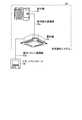
- FIG. FIG. 1is a diagram showing an example of an external configuration of a remote controller according to Embodiment 1 of the present invention.
- a remote controller 10 shown in FIG. 1includes a display unit 11 that displays an operation state represented by a set temperature and an operation mode, and an operation unit 12 that includes various operation buttons represented by an operation stop switching button and a menu button.
- the present inventionis not limited to this, and an operation display unit may be provided instead of the display unit and the operation unit.
- the operation display unitcan be realized by a touch panel.
- FIG. 2is a block diagram showing an example of the configuration of the remote controller according to Embodiment 1 of the present invention.
- the remote controller 10 shown in FIG. 2includes a display unit 11, an operation unit 12, a control unit 20, a memory 21, and a communication unit 22, and the display unit 11, the operation unit 12, the memory 21, and the communication unit 22 are , Connected to the control unit 20.
- the control unit 20is a processor that is realized by a microcomputer and controls the operation of the remote controller 10.
- the communication unit 22is configured to perform wired or wireless bidirectional communication with the indoor unit 52 of the air conditioning system 50.
- the outdoor unit 51 and the indoor unit 52constitute a part of the air conditioning system 50 controlled by the remote controller 10.
- the memory 21includes a non-volatile memory and stores at least a plurality of operation state diagnosis tables used at the time of maintenance and inspection of the air conditioning system.
- the operating state diagnosis tableis a table used for extracting necessary inspection items from the operating state of the air conditioning system.
- FIG. 3is a diagram showing an example of the configuration of a remote controller according to Embodiment 1 of the present invention and an air conditioning system to which the remote controller is connected.
- the air conditioning system 50 connected to the remote controller 10 shown in FIG. 3includes an outdoor unit 51, an indoor unit 52, an indoor / outdoor communication line 53a that connects the outdoor unit 51 and the indoor unit 52, an indoor unit 52, and a remote unit. And an indoor remote control communication line 53b for connecting to the controller 10.
- the indoor remote controller communication line 53bconnects the indoor unit 52 and the remote controller 10 is illustrated here, the present invention is not limited to this, and the remote controller 10 may be a wireless remote controller.
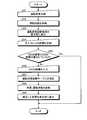
- FIG. 4is a diagram showing an example of a flowchart of an operation state diagnosis by the remote controller according to Embodiment 1 of the present invention.
- the maintenance inspector or the useroperates the operation unit 12 of the remote controller 10 using the operation state diagnosis table until the indoor unit operation time and the outdoor unit operation time reach the set time. By doing so, the operation state is checked (S11). Then, the remote controller 10 collects operation information including operation time from the outdoor unit 51 and the outdoor unit 52 via the indoor remote control communication line 53b (S12).
- the indoor unit operation time and the outdoor unit operation timeare equal for convenience and may be simply referred to as “operation time”.
- FIG. 5is a diagram showing an example of items of operation information collected at the time of inspection by the remote controller according to Embodiment 1 of the present invention.
- “outdoor discharge temperature”, “outdoor heat exchange temperature”, “indoor suction temperature”, “indoor heat exchange temperature”, “indoor unit operation time”, and “outdoor unit operation time”are listed as items.
- the numbers (1) to (6)are given in this order.
- (7)indicates that other items are included.
- the “outdoor discharge temperature”is the temperature of the air discharged by the outdoor unit
- the “indoor suction temperature”is the temperature of the air sucked by the indoor unit
- the “outdoor heat exchange temperature”is the heat of the outdoor unit. It is the temperature of the exchanger
- “indoor heat exchange temperature”is the temperature of the heat exchanger of the indoor unit.
- the remote controller 10extracts the operation time that is the indoor unit operation time and the outdoor unit operation time from the collected operation information (S13). And the operation state diagnostic table which should be used is determined from the operation time which is indoor unit operation time and outdoor unit operation time. Specifically, it is determined whether or not the driving time is equal to or shorter than the first set time (S14), and the driving state diagnosis table is properly used according to the determination result.
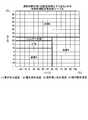
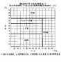
- FIG. 6is a diagram illustrating an example of the cooling operation state diagnosis table stored in the memory of the remote controller according to Embodiment 1 of the present invention when the operation time is equal to or less than the first set time.
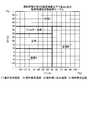
- FIG. 7is a diagram illustrating an example of the heating operating state diagnosis table stored in the memory of the remote controller according to Embodiment 1 of the present invention when the operating time is equal to or shorter than the first set time.
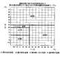
- FIG. 8shows an operating condition diagnosis table during cooling when the operation time exceeds the first set time and is less than or equal to the second set time, which is stored in the memory of the remote controller according to Embodiment 1 of the present invention. It is a figure which shows an example.
- FIG. 8shows an operating condition diagnosis table during cooling when the operation time exceeds the first set time and is less than or equal to the second set time, which is stored in the memory of the remote controller according to Embodiment 1 of the present invention. It is a figure which shows an example.
- the memory 21 of the remote controller 10includes a plurality of operation state diagnosis tables during cooling and a plurality of operation state diagnosis tables during heating.
- each operation modehas a plurality of operation state diagnosis tables.
- the horizontal axisrepresents the difference obtained by subtracting the outdoor heat exchange temperature from the outdoor discharge temperature
- the vertical axis in FIGS. 6 and 8represents the difference obtained by subtracting the indoor heat exchange temperature from the indoor suction temperature.
- the horizontal axis in FIGS. 7 and 9is the difference obtained by subtracting the indoor heat exchange temperature from the outdoor discharge temperature
- the vertical axis in FIGS. 7 and 9is the difference obtained by subtracting the indoor suction temperature from the indoor heat exchange temperature.
- the “normal” regionindicates that the operation of the air conditioning system 50 is normal, and the “filter inspection” region should perform the filter inspection included in the air conditioning system 50.
- the areas “inspection A”, “inspection B”, and “inspection C”indicate that the air conditioning system 50 should be subjected to some predetermined inspection. As an example, when the difference obtained by subtracting the outdoor heat exchange temperature from the outdoor discharge temperature is 20, and the difference obtained by subtracting the indoor heat exchange temperature from the indoor suction temperature is 15, it is determined that the air conditioning system 50 is normal. Is done.
- the operation state diagnosisis performed using the first operation state diagnosis table (S15). That is, for the cooling operation, the operation state diagnosis is performed using the cooling operation state diagnosis table shown in FIG. 6, and for the heating operation, the operation state diagnosis is performed using the heating operation state diagnosis table shown in FIG.
- the operation state diagnosisis performed using the second operation state diagnosis table (S17). That is, for the cooling operation, the operation state diagnosis is performed using the cooling operation state diagnosis table shown in FIG. 8, and for the heating operation, the operation state diagnosis is performed using the heating operation state diagnosis table shown in FIG.
- the second operation state diagnosis tableis an operation state diagnosis table when the operation time exceeds the first set time and is equal to or less than the second set time.
- FIG. 10is a diagram illustrating an example of a display screen of a driving state diagnosis result during normal operation when the operation time is equal to or shorter than the first set time. In FIG. 10, it is displayed that the air conditioning system 50 is operating normally.
- FIG. 11is a diagram illustrating an example of a display screen of a driving state diagnosis result when an abnormality occurs when the driving time is equal to or shorter than the first set time. In FIG. 11, it is displayed on the display screen that detailed inspection is necessary.
- the detailed inspectionrefers to an inspection performed manually by a maintenance inspector or a user with respect to an abnormal point displayed by the operation state diagnosis.
- the detailed inspectionmay be an inspection in which the filter is removed from the air conditioning system and visually confirmed when the operation state diagnosis is “filter inspection”.
- the air conditioning systemincludes a plurality of indoor units, and the result of maintenance data in the indoor unit of “refrigerant address 0” which is one of the plurality of indoor units is shown.
- the first operation state diagnosis tableis shown in FIG.
- the operation state diagnosisis performed using the cooling operation state diagnosis table shown or the heating operation state diagnosis table shown in FIG. 7 and the operation state diagnosis is performed three years after the installation of the air conditioning system 50
- the second The operating state diagnosisis performed using the cooling operation state diagnosis table shown in FIG. 8 and the heating operation state diagnosis table shown in FIG.
- the present inventionis not limited to this.
- the setting timemay be further divided and three or more types of operation state diagnosis tables may be selectively used in each operation mode.
- a plurality of operation state diagnosis tablesare stored in the memory of the remote controller, and these are used properly according to the operation mode and operation time of the air conditioning system. If it is determined whether or not the current operation time is less than or equal to the set operation time threshold, and a plurality of operation state diagnosis tables stored in the memory of the remote controller can be automatically switched based on the determination result Even after many years of use, it is possible to perform a driving state diagnosis with high accuracy.
- Embodiment 2The operation state diagnosis table described in the first embodiment is created from the test data, and does not take into account the installation environment and operation conditions such as installation conditions or temperature conditions. Therefore, if the installation environment and operation status are different from the installation environment and operation status assumed at the time of test data acquisition, it is installed in the server room as an example, and when cooling is used throughout the year in winter It is not appropriate to use the operation state diagnosis table described in the first embodiment because it may deviate from the installation environment and operation state assumed at the time of obtaining test data. In the second embodiment, even when the installation environment and the operation status are different from the installation environment and the operation status assumed at the time of obtaining the test data, the operation diagnosis table is provided so that highly accurate operation status diagnosis is possible. The form which correct
- FIG. 12is a diagram showing an example of a flowchart of the operation state diagnosis by the remote controller according to the second embodiment.
- the remote controller 10performs an operation state check by operating the remote controller 10 (S21).
- the remote controller 10diagnoses the operation state from the operation information collected along with the operation state inspection (S22), and displays the operation state diagnosis result on the display unit 11 (S23).
- the remote controller 10determines the result of S22 and S24. It is determined whether the results are consistent (S25). If the result of determination in S25 is that the result of S22 matches the result of S24 (S25: Yes), the operation is terminated. If the result of S22 and the result of S24 do not match (S25: No), the remote controller 10 prompts the remote controller 10 to input the result of S24, and the result of S24 is input to the remote controller 10. (S26).
- the remote controller 10corrects the operation state diagnosis table from the result of S24 input in S26 (S27), and again performs the operation state diagnosis in the same manner as S22 (S28). Thereafter, the remote controller 10 displays the corrected result on the display unit 11 (S29).
- the diagnosis resultis “normal” in S22 and “normal” without any abnormality even if a detailed inspection is performed in S24, or the diagnosis result is “filter inspection” in S22. If the filter is actually clogged after a detailed inspection in S24, it can be said that the result of S22 is consistent with the result of S24.
- diagnosis resultis “normal” in S22 and the filter is actually clogged after detailed inspection in S24, or the diagnosis result is “filter inspection” in S22 and detailed in S24. If it is “normal” without any abnormality even after the inspection, the result of S22 and the result of S24 are not consistent.
- FIG. 13is a diagram showing an example of an operation state diagnosis table in which the operation state diagnosis results by the remote controller in S22 are plotted.
- the operation state diagnosis resultdeviates from the normal range, and an indication that inspection B should be performed is displayed.
- a detailed inspection in S24revealed that the inspection B is actually unnecessary and normal. Therefore, the remote controller 10 corrects the operation state diagnosis table.
- FIG. 14is a diagram illustrating an example of the operation state diagnosis table corrected in S27.
- the operation state diagnosis resultis within the normal range by correcting the operation state diagnosis table.
- the operation state diagnosis table stored in the memory of the remote controllercan be corrected according to the installation environment and the operation state.
- the configuration described in the above embodimentshows an example of the contents of the present invention, and can be combined with another known technique, and can be combined with other configurations without departing from the gist of the present invention. It is also possible to omit or change the part.
- 10 remote controller11 display unit, 12 operation unit, 20 control unit, 21 memory, 22 communication unit, 50 air conditioning system, 51 outdoor unit, 52 indoor unit, 53a indoor outdoor communication line, 53b indoor remote control communication line.
Landscapes
- Engineering & Computer Science (AREA)
- Chemical & Material Sciences (AREA)
- Combustion & Propulsion (AREA)
- Mechanical Engineering (AREA)
- General Engineering & Computer Science (AREA)
- Physics & Mathematics (AREA)
- Fuzzy Systems (AREA)
- Mathematical Physics (AREA)
- Signal Processing (AREA)
- Air Conditioning Control Device (AREA)
Abstract
Description
Translated fromJapanese本発明は、室外機と室内機とを有する空気調和システムのリモートコントローラに関する。The present invention relates to a remote controller of an air conditioning system having an outdoor unit and an indoor unit.
従来、空気調和システムの点検時に保守点検員、すなわちサービスマンが空気調和システムの運転状態を容易に確認できるように、リモートコントローラが収集した空気調和システムの運転状態の情報から、運転状態診断テーブルを用いて空気調和システムの運転状態を診断して、診断結果を表示画面に表示する空気調和システムが実用化されている。Conventionally, a maintenance inspection table, based on the information on the air conditioner system's operating state collected by the remote controller, can be used by maintenance personnel, i.e., service personnel, to easily check the air conditioner system's operating condition when checking the air conditioner system. An air conditioning system that diagnoses the operating condition of the air conditioning system and displays the diagnosis result on a display screen has been put into practical use.
事前に設定されたしきい値と現在の状態量を比較して故障診断を行う技術の一例である特許文献1には、「従来の冷凍装置の故障診断方法は、過去のデータの蓄積により設定された閾値や事前に設定された閾値と現在の状態量を比較することで冷凍装置の状態を把握しており、能力制御可能な圧縮機を搭載した冷凍装置において故障診断を行うためには冷凍能力が変化する度に閾値を変更したり、冷凍能力毎に事前に閾値を設定する必要があった」ことを課題とし、「冷凍装置の現在の計測値のみから冷凍装置及び圧縮機の正常な入力値を予測し、入力値の実測値との比較を行うことで、冷凍能力が変化した場合でも精度良く故障診断を簡単に行うことを可能とした」冷凍装置が開示されている。
しかしながら、上記従来の技術によれば、現在の運転状態を診断する運転状態診断テーブルは経年劣化を考慮しておらず、使用開始時から変更されることなく同一の運転状態診断テーブルが使用される。そのため、使用開始直後には精度の高い運転状態診断が可能であるが、長年の使用によって空気調和システムが経年劣化すると、運転状態診断の精度が低下する、という問題があった。However, according to the above-described conventional technology, the operation state diagnosis table for diagnosing the current operation state does not consider aged deterioration, and the same operation state diagnosis table is used without being changed from the start of use. . For this reason, it is possible to perform a highly accurate operation state diagnosis immediately after the start of use, but there is a problem that the accuracy of the operation state diagnosis is lowered when the air conditioning system deteriorates over time due to long-term use.
本発明は、上記に鑑みてなされたものであって、長年使用した後であっても高い精度で運転状態診断を行うことが可能な空気調和システムのリモートコントローラを得ることを目的とする。The present invention has been made in view of the above, and an object of the present invention is to obtain a remote controller of an air conditioning system capable of performing an operation state diagnosis with high accuracy even after being used for many years.
上述した課題を解決し、目的を達成するために、本発明に係る空気調和システムのリモートコントローラは、室外機及び該室外機に接続された室内機を備える空気調和システムのリモートコントローラであって、前記室内機と有線又は無線による双方向通信可能な通信部と、前記空気調和システムの保守点検時に用いる、運転状態診断テーブルを動作モード毎に複数記憶したメモリとを備え、複数の前記運転状態診断テーブルは、前記空気調和システムの動作モード及び運転時間に応じて使い分けられることを特徴とする。In order to solve the above-described problems and achieve the object, a remote controller of an air conditioning system according to the present invention is an air conditioning system remote controller including an outdoor unit and an indoor unit connected to the outdoor unit, A communication unit capable of two-way communication with the indoor unit by wire or wireless, and a memory that stores a plurality of operation state diagnosis tables for each operation mode, which is used at the time of maintenance and inspection of the air conditioning system. The table is selectively used according to an operation mode and an operation time of the air conditioning system.
本発明に係る空気調和システムのリモートコントローラは、長年使用した後であっても高い精度で運転状態診断を行うことが可能な空気調和システムのリモートコントローラを得ることができるという効果を奏する。The remote controller of the air conditioning system according to the present invention has an effect that it is possible to obtain a remote controller of an air conditioning system that can perform an operation state diagnosis with high accuracy even after being used for many years.
以下に、本発明の実施の形態に係る空気調和システムのリモートコントローラを図面に基づいて詳細に説明する。なお、この実施の形態によりこの発明が限定されるものではない。Hereinafter, a remote controller of an air conditioning system according to an embodiment of the present invention will be described in detail with reference to the drawings. Note that the present invention is not limited to the embodiments.
実施の形態1.
図1は、本発明の実施の形態1に係るリモートコントローラの外観構成の一例を示す図である。図1に示すリモートコントローラ10は、設定温度及び運転モードに代表される運転状態を表示する表示部11と、運転停止切替ボタン及びメニューボタンに代表される各種操作ボタンを有する操作部12とを備える。ただし、本発明はこれに限定されず、表示部及び操作部に代えて操作表示部を備えていてもよい。なお、操作表示部は、タッチパネルにより実現することができる。
FIG. 1 is a diagram showing an example of an external configuration of a remote controller according to
図2は、本発明の実施の形態1に係るリモートコントローラの構成の一例を示すブロック図である。図2に示すリモートコントローラ10は、表示部11と、操作部12と、制御部20と、メモリ21と、通信部22とを備え、表示部11、操作部12、メモリ21及び通信部22は、制御部20に接続されている。制御部20は、マイクロコンピュータにより実現され、リモートコントローラ10の動作を制御するプロセッサである。通信部22は、空気調和システム50の室内機52との有線又は無線による双方向通信を行う構成である。なお、室外機51及び室内機52は、リモートコントローラ10によって制御される空気調和システム50の一部を構成している。メモリ21は、不揮発性メモリを備え、少なくとも空気調和システムの保守点検時に用いる運転状態診断テーブルを複数記憶している。なお、運転状態診断テーブルは、空気調和システムの運転状態から必要な点検項目を抽出するために用いられるテーブルである。FIG. 2 is a block diagram showing an example of the configuration of the remote controller according to
図3は、本発明の実施の形態1に係るリモートコントローラと、該リモートコントローラが接続された空気調和システムの構成の一例を示す図である。図3に示すリモートコントローラ10が接続された空気調和システム50は、室外機51と、室内機52と、室外機51と室内機52とを接続する室内室外通信線53aと、室内機52とリモートコントローラ10とを接続する室内リモコン通信線53bとを備える。なお、ここでは室内リモコン通信線53bが室内機52とリモートコントローラ10とを接続する場合を例示したが、本発明はこれに限定されず、リモートコントローラ10はワイヤレスリモコンであってもよい。FIG. 3 is a diagram showing an example of the configuration of a remote controller according to
図4は、本発明の実施の形態1に係るリモートコントローラによる運転状態診断のフローチャートの一例を示す図である。図3に示す空気調和システム50において、保守点検員又はユーザーは、室内機運転時間及び室外機運転時間が設定時間に達するまでの運転状態診断テーブルを用いて、リモートコントローラ10の操作部12を操作することによって運転状態点検を行う(S11)。そして、リモートコントローラ10は、室内リモコン通信線53bを介して室外機51及び室外機52から運転時間を含む運転情報を収集する(S12)。なお、本実施の形態1では室内機運転時間と室外機運転時間は便宜上等しくし、単に「運転時間」と記載する場合があるものとする。FIG. 4 is a diagram showing an example of a flowchart of an operation state diagnosis by the remote controller according to
図5は、本発明の実施の形態1に係るリモートコントローラが点検時に収集する運転情報の項目の一例を示す図である。図5には、項目として「室外吐出温度」、「室外熱交温度」、「室内吸い込み温度」、「室内熱交温度」、「室内機運転時間」及び「室外機運転時間」が挙げられており、この順に(1)から(6)の番号が付されている。なお、図5において、これらの項目は例示であるため、(7)にはその他の項目が含まれることを表している。なお、「室外吐出温度」は、室外機が吐出する空気の温度であり、「室内吸い込み温度」は、室内機が吸い込む空気の温度であり、「室外熱交温度」は、室外機が有する熱交換器の温度であり、「室内熱交温度」は、室内機が有する熱交換器の温度である。FIG. 5 is a diagram showing an example of items of operation information collected at the time of inspection by the remote controller according to
リモートコントローラ10は、収集した運転情報から室内機運転時間及び室外機運転時間である運転時間を抽出する(S13)。そして、室内機運転時間及び室外機運転時間である運転時間から使用すべき運転状態診断テーブルを判定する。具体的には、運転時間が第1の設定時間以下か否かの判定を行い(S14)、この判定結果に応じて運転状態診断テーブルを使い分ける。The
図6は、本発明の実施の形態1に係るリモートコントローラのメモリに記憶された、運転時間が第1の設定時間以下であるときの冷房時運転状態診断テーブルの一例を示す図である。図7は、本発明の実施の形態1に係るリモートコントローラのメモリに記憶された、運転時間が第1の設定時間以下であるときの暖房時運転状態診断テーブルの一例を示す図である。図8は、本発明の実施の形態1に係るリモートコントローラのメモリに記憶された、運転時間が第1の設定時間を超えて第2の設定時間以下であるときの冷房時運転状態診断テーブルの一例を示す図である。図9は、本発明の実施の形態1に係るリモートコントローラのメモリに記憶された、運転時間が第1の設定時間を超えて第2の設定時間以下であるときの暖房時運転状態診断テーブルの一例を示す図である。このようにリモートコントローラ10のメモリ21には、冷房時における運転状態診断テーブル及び暖房時における運転状態診断テーブルを、各々複数有する。すなわち、動作モード毎に複数の運転状態診断テーブルを有する。なお、図6,8における横軸は室外吐出温度から室外熱交温度を引いた差分であり、図6,8における縦軸は室内吸い込み温度から室内熱交温度を引いた差分である。また、図7,9における横軸は室外吐出温度から室内熱交温度を引いた差分であり、図7,9における縦軸は室内熱交温度から室内吸い込み温度を引いた差分である。FIG. 6 is a diagram illustrating an example of the cooling operation state diagnosis table stored in the memory of the remote controller according to
図6,7,8,9において、「正常」の領域は空気調和システム50の動作が正常であることを示し、「フィルター点検」の領域は、空気調和システム50に含まれるフィルター点検を行うべき状態であることを示し、「点検A」、「点検B」及び「点検C」の領域は、空気調和システム50に対して何らかの既定の点検を行うべき状態であることを示している。一例として、室外吐出温度から室外熱交温度を引いた差分が20であり、室内吸い込み温度から室内熱交温度を引いた差分が15である場合には、空気調和システム50は正常であると判断される。6, 7, 8, and 9, the “normal” region indicates that the operation of the
ここで、運転時間が第1の設定時間以下であるとき(S14:Yes)には、第1の運転状態診断テーブルを使用して運転状態診断を行う(S15)。すなわち、冷房運転に関しては図6に示す冷房時運転状態診断テーブルを使用して運転状態診断を行い、暖房運転に関しては図7に示す暖房時運転状態診断テーブルを使用して運転状態診断を行う。又は、運転時間が第1の設定時間を超えているとき(S14:No)には、第2の運転状態診断テーブルを使用して運転状態診断を行う(S17)。すなわち、冷房運転に関しては図8に示す冷房時運転状態診断テーブルを使用して運転状態診断を行い、暖房運転に関しては図9に示す暖房時運転状態診断テーブルを使用して運転状態診断を行う。なお、第2の運転状態診断テーブルは、運転時間が第1の設定時間を超えて第2の設定時間以下であるときの運転状態診断テーブルである。Here, when the operation time is equal to or shorter than the first set time (S14: Yes), the operation state diagnosis is performed using the first operation state diagnosis table (S15). That is, for the cooling operation, the operation state diagnosis is performed using the cooling operation state diagnosis table shown in FIG. 6, and for the heating operation, the operation state diagnosis is performed using the heating operation state diagnosis table shown in FIG. Alternatively, when the operation time exceeds the first set time (S14: No), the operation state diagnosis is performed using the second operation state diagnosis table (S17). That is, for the cooling operation, the operation state diagnosis is performed using the cooling operation state diagnosis table shown in FIG. 8, and for the heating operation, the operation state diagnosis is performed using the heating operation state diagnosis table shown in FIG. The second operation state diagnosis table is an operation state diagnosis table when the operation time exceeds the first set time and is equal to or less than the second set time.
そして、S14における分岐に関わらず、この運転状態診断結果をリモートコントローラ10の表示部11に表示する(S16)。図10は、運転時間が第1の設定時間以下である場合であって正常運転時の運転状態診断結果の表示画面の一例を示す図である。図10においては空気調和システム50が正常運転している旨が表示されている。図11は、運転時間が第1の設定時間以下である場合であって異常発生時の運転状態診断結果の表示画面の一例を示す図である。図11においては、表示画面には詳細な点検が必要である旨が表示されている。ここで、詳細な点検は、運転状態診断によって表示された異常箇所に対して保守点検員又はユーザーが手操作で行う点検をいう。詳細な点検には、運転状態診断が「フィルター点検」である場合にフィルターを空気調和システムから取り外して目視確認する点検を例示することができる。なお、ここでは、空気調和システムが複数の室内機を備え、この複数の室内機の1つである「冷媒アドレス0」の室内機におけるメンテナンスデータ結果を示している。Then, regardless of the branch in S14, the operation state diagnosis result is displayed on the
具体例にて説明すると、第1の設定時間を一例として2年間とし、空気調和システム50の設置から1年後に運転状態診断を行う場合には、第1の運転状態診断テーブルである図6に示す冷房時運転状態診断テーブル又は図7に示す暖房時運転状態診断テーブルを使用して運転状態の診断を行い、空気調和システム50の設置から3年後に運転状態診断を行う場合には、第2の運転状態診断テーブルである図8に示す冷房時運転状態診断テーブル及び図9に示す暖房時運転状態診断テーブルを使用して運転状態の診断を行う。Specifically, in the case where the first set time is set to two years as an example, and the operation state diagnosis is performed one year after the installation of the
なお、本実施の形態1においては、冷房及び暖房の各々において2種類の運転状態診断テーブルを示しているが、本発明はこれに限定されるものではない。リモートコントローラ10のメモリ21の容量が大きい場合には、設定時間をさらに細かく分けて、各動作モードにおいて3種類以上の運転状態診断テーブルを使い分ける構成であってもよい。In the first embodiment, two types of operation state diagnosis tables are shown for each of cooling and heating, but the present invention is not limited to this. When the capacity of the
本実施の形態1にて説明したように、リモートコントローラのメモリに複数の運転状態診断テーブルが記憶され、これらが空気調和システムの動作モード及び運転時間に応じて使い分けられ、室内機及び室外機の現在の運転時間が、設定された運転時間のしきい値以下であるか否かを判定し、この判定結果によってリモートコントローラのメモリに記憶された複数の運転状態診断テーブルを自動で切替可能とすると、長年使用した後であっても高い精度で運転状態診断を行うことができる。As described in the first embodiment, a plurality of operation state diagnosis tables are stored in the memory of the remote controller, and these are used properly according to the operation mode and operation time of the air conditioning system. If it is determined whether or not the current operation time is less than or equal to the set operation time threshold, and a plurality of operation state diagnosis tables stored in the memory of the remote controller can be automatically switched based on the determination result Even after many years of use, it is possible to perform a driving state diagnosis with high accuracy.
実施の形態2.
実施の形態1において説明した運転状態診断テーブルは、試験データから作成されるものであり、据付条件又は温度条件といった設置環境及び運転状況を考慮したものではない。そのため、設置環境及び運転状況が試験データ取得時に想定された設置環境及び運転状況と異なる場合、一例としてサーバールームに設置されて通年で冬場でも冷房を使用している状況である場合には、実施の形態1において説明した運転状態診断テーブルを用いることは試験データ取得時に想定された設置環境及び運転状況と乖離している場合があるため適切ではない。本実施の形態2においては、設置環境及び運転状況が、試験データ取得時に想定された設置環境及び運転状況と異なる場合であっても、精度の高い運転状態診断が可能となるように運転診断テーブルを補正する形態について説明する。
The operation state diagnosis table described in the first embodiment is created from the test data, and does not take into account the installation environment and operation conditions such as installation conditions or temperature conditions. Therefore, if the installation environment and operation status are different from the installation environment and operation status assumed at the time of test data acquisition, it is installed in the server room as an example, and when cooling is used throughout the year in winter It is not appropriate to use the operation state diagnosis table described in the first embodiment because it may deviate from the installation environment and operation state assumed at the time of obtaining test data. In the second embodiment, even when the installation environment and the operation status are different from the installation environment and the operation status assumed at the time of obtaining the test data, the operation diagnosis table is provided so that highly accurate operation status diagnosis is possible. The form which correct | amends is demonstrated.
図12は、本実施の形態2に係るリモートコントローラによる運転状態診断のフローチャートの一例を示す図である。まず、実施の形態1と同様に、リモートコントローラ10の操作により、リモートコントローラ10は運転状態点検を行う(S21)。リモートコントローラ10は、運転状態点検に伴って収集した運転情報から運転状態を診断し(S22)、運転状態診断結果を表示部11に表示する(S23)。FIG. 12 is a diagram showing an example of a flowchart of the operation state diagnosis by the remote controller according to the second embodiment. First, as in the first embodiment, the
次に、手入力による詳細な点検、すなわち運転状態診断によって表示された異常箇所に対して保守点検員又はユーザーの手操作による点検を行い(S24)、リモートコントローラ10は、S22の結果とS24の結果が整合しているか否かの判定を行う(S25)。S25における判定の結果、S22の結果とS24の結果が整合している場合には(S25:Yes)、動作を終了する。S22の結果とS24の結果が整合していない場合には(S25:No)、リモートコントローラ10はS24の結果をリモートコントローラ10に入力するよう促し、リモートコントローラ10にはS24の結果が入力される(S26)。リモートコントローラ10は、S26で入力されたS24の結果から運転状態診断テーブルを補正し(S27)、再度、S22と同様に運転状態診断を行う(S28)。その後、リモートコントローラ10は、補正した結果を表示部11に表示する(S29)。ここで、S22において診断結果が「正常」であってS24において詳細な点検を行っても何らの異常もなく「正常」であった場合、又は、S22において診断結果が「フィルター点検」であってS24において詳細な点検を行うとフィルターが実際に目詰まりしていた場合には、S22の結果とS24の結果が整合しているといえる。しかしながら、S22において診断結果が「正常」であってS24において詳細な点検を行うとフィルターが実際に目詰まりしていた場合、又は、S22において診断結果が「フィルター点検」であってS24において詳細な点検を行っても何らの異常もなく「正常」であった場合には、S22の結果とS24の結果は整合していない。Next, detailed inspection by manual input, that is, inspection by the manual operation of the maintenance inspector or the user is performed on the abnormal part displayed by the operation state diagnosis (S24), and the
図13は、S22におけるリモートコントローラによる運転状態診断結果をプロットした運転状態診断テーブルの一例を示す図である。図13において、運転状態診断結果は正常範囲から逸脱し、点検Bを行うべき旨が表示されている。しかしながら、S24における詳細な点検によると、実際には点検Bは不要であり正常であることが明らかとなった。そこで、リモートコントローラ10は、運転状態診断テーブルの補正を行う。FIG. 13 is a diagram showing an example of an operation state diagnosis table in which the operation state diagnosis results by the remote controller in S22 are plotted. In FIG. 13, the operation state diagnosis result deviates from the normal range, and an indication that inspection B should be performed is displayed. However, a detailed inspection in S24 revealed that the inspection B is actually unnecessary and normal. Therefore, the
図14は、S27において補正された運転状態診断テーブルの一例を示す図である。図14においては、運転状態診断テーブルの補正によって、運転状態診断結果が正常範囲内に収まっている。FIG. 14 is a diagram illustrating an example of the operation state diagnosis table corrected in S27. In FIG. 14, the operation state diagnosis result is within the normal range by correcting the operation state diagnosis table.
以上説明したように、リモートコントローラのメモリに記憶された運転状態診断テーブルを設置環境及び運転状況に応じて補正することができる。As described above, the operation state diagnosis table stored in the memory of the remote controller can be corrected according to the installation environment and the operation state.
以上の実施の形態に示した構成は、本発明の内容の一例を示すものであり、別の公知の技術と組み合わせることも可能であるし、本発明の要旨を逸脱しない範囲で、構成の一部を省略、変更することも可能である。The configuration described in the above embodiment shows an example of the contents of the present invention, and can be combined with another known technique, and can be combined with other configurations without departing from the gist of the present invention. It is also possible to omit or change the part.
10 リモートコントローラ、11 表示部、12 操作部、20 制御部、21 メモリ、22 通信部、50 空気調和システム、51 室外機、52 室内機、53a 室内室外通信線、53b 室内リモコン通信線。10 remote controller, 11 display unit, 12 operation unit, 20 control unit, 21 memory, 22 communication unit, 50 air conditioning system, 51 outdoor unit, 52 indoor unit, 53a indoor outdoor communication line, 53b indoor remote control communication line.
Claims (3)
Translated fromJapanese前記室内機と有線又は無線による双方向通信可能な通信部と、
前記空気調和システムの保守点検時に用いる、運転状態診断テーブルを動作モード毎に複数記憶したメモリとを備え、
複数の前記運転状態診断テーブルは、前記空気調和システムの動作モード及び運転時間に応じて使い分けられることを特徴とする空気調和システムのリモートコントローラ。A remote controller of an air conditioning system including an outdoor unit and an indoor unit connected to the outdoor unit,
A communication unit capable of bidirectional communication with the indoor unit by wire or wireless,
A memory that stores a plurality of operation state diagnosis tables for each operation mode, used at the time of maintenance and inspection of the air conditioning system,
The remote controller for an air conditioning system, wherein the plurality of operating state diagnosis tables are selectively used according to an operation mode and an operation time of the air conditioning system.
Priority Applications (5)
| Application Number | Priority Date | Filing Date | Title |
|---|---|---|---|
| PCT/JP2015/065132WO2016189665A1 (en) | 2015-05-26 | 2015-05-26 | Remote controller for air conditioning system |
| US15/554,787US10365002B2 (en) | 2015-05-26 | 2015-05-26 | Remote controller of air-conditioning system |
| JP2017520133AJP6355837B2 (en) | 2015-05-26 | 2015-05-26 | Remote controller for air conditioning system |
| EP15864299.1AEP3214384B1 (en) | 2015-05-26 | 2015-05-26 | Remote controller for air conditioning system |
| CN201580079038.5ACN108307650B (en) | 2015-05-26 | 2015-05-26 | Remote controller for air conditioning system |
Applications Claiming Priority (1)
| Application Number | Priority Date | Filing Date | Title |
|---|---|---|---|
| PCT/JP2015/065132WO2016189665A1 (en) | 2015-05-26 | 2015-05-26 | Remote controller for air conditioning system |
Publications (1)
| Publication Number | Publication Date |
|---|---|
| WO2016189665A1true WO2016189665A1 (en) | 2016-12-01 |
Family
ID=57393903
Family Applications (1)
| Application Number | Title | Priority Date | Filing Date |
|---|---|---|---|
| PCT/JP2015/065132CeasedWO2016189665A1 (en) | 2015-05-26 | 2015-05-26 | Remote controller for air conditioning system |
Country Status (5)
| Country | Link |
|---|---|
| US (1) | US10365002B2 (en) |
| EP (1) | EP3214384B1 (en) |
| JP (1) | JP6355837B2 (en) |
| CN (1) | CN108307650B (en) |
| WO (1) | WO2016189665A1 (en) |
Cited By (1)
| Publication number | Priority date | Publication date | Assignee | Title |
|---|---|---|---|---|
| WO2018154768A1 (en)* | 2017-02-27 | 2018-08-30 | 三菱電機株式会社 | Air conditioner |
Families Citing this family (4)
| Publication number | Priority date | Publication date | Assignee | Title |
|---|---|---|---|---|
| US10401830B2 (en)* | 2015-08-14 | 2019-09-03 | Emerson Electric Co. | Remotely testing whether a climate control system controller is correctly installed |
| US11366461B2 (en) | 2015-08-14 | 2022-06-21 | Emerson Electric Co. | Remotely testing whether a climate control system controller is correctly installed |
| CN115406053A (en)* | 2022-09-02 | 2022-11-29 | 珠海格力电器股份有限公司 | Air conditioner internal and external unit communication method, device, air conditioner and storage medium |
| CN119128434B (en)* | 2024-08-26 | 2025-05-16 | 北京海淀中京工程设计软件技术有限公司 | Petrochemical equipment operation supervision system and method based on visualization |
Citations (4)
| Publication number | Priority date | Publication date | Assignee | Title |
|---|---|---|---|---|
| JP2003161495A (en)* | 2001-11-21 | 2003-06-06 | Yamatake Corp | Air conditioner abnormality detection device, abnormality detection method and program |
| JP2008057921A (en) | 2006-09-01 | 2008-03-13 | Sanyo Electric Co Ltd | Refrigeration equipment |
| JP2010210121A (en)* | 2009-03-09 | 2010-09-24 | Mitsubishi Electric Corp | Air conditioner |
| JP2013174385A (en)* | 2012-02-24 | 2013-09-05 | Mitsubishi Electric Corp | Air conditioner system, and remote controller |
Family Cites Families (9)
| Publication number | Priority date | Publication date | Assignee | Title |
|---|---|---|---|---|
| JPH0776724B2 (en)* | 1988-02-18 | 1995-08-16 | 富士重工業株式会社 | Vehicle diagnostic device |
| JPH04347444A (en)* | 1991-05-23 | 1992-12-02 | Toshiba Corp | Outdoor device information display system of air conditioner |
| JP2000065415A (en)* | 1998-08-19 | 2000-03-03 | Sanyo Electric Co Ltd | Air conditioner |
| JP2003172567A (en) | 2001-04-24 | 2003-06-20 | Fuji Electric Co Ltd | Failure diagnosis method, failure diagnosis device, in-store equipment management system, and recording medium |
| JP2003316423A (en)* | 2002-04-25 | 2003-11-07 | Daikin Ind Ltd | Equipment diagnostic equipment and equipment diagnostic system |
| EP1936294B1 (en)* | 2006-09-20 | 2013-07-31 | Mitsubishi Electric Corporation | Air conditioning system |
| AU2012200300B2 (en)* | 2011-01-20 | 2015-08-20 | Fujitsu General Limited | Air conditioner |
| JP5425282B1 (en)* | 2012-08-31 | 2014-02-26 | 三菱電機株式会社 | Remote control system, system controller and program |
| CN104566838B (en)* | 2015-02-02 | 2017-11-14 | 珠海格力电器股份有限公司 | Fault detection method and device of air conditioner |
- 2015
- 2015-05-26EPEP15864299.1Apatent/EP3214384B1/enactiveActive
- 2015-05-26WOPCT/JP2015/065132patent/WO2016189665A1/ennot_activeCeased
- 2015-05-26JPJP2017520133Apatent/JP6355837B2/ennot_activeExpired - Fee Related
- 2015-05-26USUS15/554,787patent/US10365002B2/enactiveActive
- 2015-05-26CNCN201580079038.5Apatent/CN108307650B/ennot_activeExpired - Fee Related
Patent Citations (4)
| Publication number | Priority date | Publication date | Assignee | Title |
|---|---|---|---|---|
| JP2003161495A (en)* | 2001-11-21 | 2003-06-06 | Yamatake Corp | Air conditioner abnormality detection device, abnormality detection method and program |
| JP2008057921A (en) | 2006-09-01 | 2008-03-13 | Sanyo Electric Co Ltd | Refrigeration equipment |
| JP2010210121A (en)* | 2009-03-09 | 2010-09-24 | Mitsubishi Electric Corp | Air conditioner |
| JP2013174385A (en)* | 2012-02-24 | 2013-09-05 | Mitsubishi Electric Corp | Air conditioner system, and remote controller |
Non-Patent Citations (1)
| Title |
|---|
| See also references ofEP3214384A4 |
Cited By (2)
| Publication number | Priority date | Publication date | Assignee | Title |
|---|---|---|---|---|
| WO2018154768A1 (en)* | 2017-02-27 | 2018-08-30 | 三菱電機株式会社 | Air conditioner |
| JPWO2018154768A1 (en)* | 2017-02-27 | 2019-11-07 | 三菱電機株式会社 | Air conditioner |
Also Published As
| Publication number | Publication date |
|---|---|
| EP3214384A4 (en) | 2017-09-06 |
| CN108307650A (en) | 2018-07-20 |
| EP3214384A1 (en) | 2017-09-06 |
| US10365002B2 (en) | 2019-07-30 |
| JP6355837B2 (en) | 2018-07-11 |
| US20180038608A1 (en) | 2018-02-08 |
| EP3214384B1 (en) | 2020-11-18 |
| CN108307650B (en) | 2020-09-18 |
| JPWO2016189665A1 (en) | 2017-08-10 |
Similar Documents
| Publication | Publication Date | Title |
|---|---|---|
| JP6355837B2 (en) | Remote controller for air conditioning system | |
| US7308384B2 (en) | Ordered record of system-wide fault in an HVAC system | |
| US10823440B2 (en) | Systems and methods for interactive HVAC maintenance interface | |
| US20170010014A1 (en) | Air conditioner test operation application, and air conditioner test operation system | |
| US7500368B2 (en) | System and method for verifying proper refrigerant and airflow for air conditioners and heat pumps in cooling mode | |
| US8521356B2 (en) | Air conditioner for vehicle, and system and method of vehicle air-conditioning management | |
| US8527097B2 (en) | Air conditioning management apparatus, air conditioning management method, air conditioning system, program, and recording medium | |
| ES2954625T3 (en) | Device management system | |
| KR100640851B1 (en) | Apparatus and method for monitoring status of multi-air conditioner | |
| CN104034998B (en) | Diagnosis method and system for wrong connection of internal and external machine connecting wires of fixed-frequency air conditioner | |
| EP2950010B1 (en) | Air conditioner | |
| CN108954670B (en) | Fault pre-judging method and control system of air conditioner and air conditioner | |
| US11754306B2 (en) | HVAC zone control panel electronic display systems and methods | |
| JP2019060539A (en) | Air conditioner | |
| US11913659B2 (en) | Systems and methods for monitoring operation of an HVAC system | |
| JP2012127625A (en) | Fault diagnosis apparatus to be used for air conditioning apparatus | |
| JP6141217B2 (en) | Compressor deterioration diagnosis device and compressor deterioration diagnosis method | |
| KR101871724B1 (en) | Control method of air conditioning apparatus | |
| US8001230B2 (en) | Group management apparatus and group management system | |
| JP3102208B2 (en) | Operation control device for air conditioner | |
| JP6625196B2 (en) | Air conditioning system | |
| JP2005049001A (en) | Air conditioner | |
| JP6852850B2 (en) | Diagnostic method and diagnostic equipment for air conditioners | |
| JP2005282903A (en) | Air conditioner | |
| JP2006090614A (en) | Air conditioner |
Legal Events
| Date | Code | Title | Description |
|---|---|---|---|
| REEP | Request for entry into the european phase | Ref document number:2015864299 Country of ref document:EP | |
| WWE | Wipo information: entry into national phase | Ref document number:2015864299 Country of ref document:EP | |
| 121 | Ep: the epo has been informed by wipo that ep was designated in this application | Ref document number:15864299 Country of ref document:EP Kind code of ref document:A1 | |
| ENP | Entry into the national phase | Ref document number:2017520133 Country of ref document:JP Kind code of ref document:A | |
| WWE | Wipo information: entry into national phase | Ref document number:15554787 Country of ref document:US | |
| NENP | Non-entry into the national phase | Ref country code:DE |