WO2016181724A1 - Resin distal end component for endoscope - Google Patents
Resin distal end component for endoscopeDownload PDFInfo
- Publication number
- WO2016181724A1 WO2016181724A1PCT/JP2016/061029JP2016061029WWO2016181724A1WO 2016181724 A1WO2016181724 A1WO 2016181724A1JP 2016061029 WJP2016061029 WJP 2016061029WWO 2016181724 A1WO2016181724 A1WO 2016181724A1
- Authority
- WO
- WIPO (PCT)
- Prior art keywords
- outer layer
- transparent resin
- disposed
- resin
- tip
- Prior art date
- Legal status (The legal status is an assumption and is not a legal conclusion. Google has not performed a legal analysis and makes no representation as to the accuracy of the status listed.)
- Ceased
Links
Images


Classifications
- A—HUMAN NECESSITIES
- A61—MEDICAL OR VETERINARY SCIENCE; HYGIENE
- A61B—DIAGNOSIS; SURGERY; IDENTIFICATION
- A61B1/00—Instruments for performing medical examinations of the interior of cavities or tubes of the body by visual or photographical inspection, e.g. endoscopes; Illuminating arrangements therefor
- A61B1/00064—Constructional details of the endoscope body
- A61B1/00071—Insertion part of the endoscope body
- A61B1/0008—Insertion part of the endoscope body characterised by distal tip features
- A61B1/00096—Optical elements
- A—HUMAN NECESSITIES
- A61—MEDICAL OR VETERINARY SCIENCE; HYGIENE
- A61B—DIAGNOSIS; SURGERY; IDENTIFICATION
- A61B1/00—Instruments for performing medical examinations of the interior of cavities or tubes of the body by visual or photographical inspection, e.g. endoscopes; Illuminating arrangements therefor
- A61B1/00064—Constructional details of the endoscope body
- A61B1/0011—Manufacturing of endoscope parts
- A—HUMAN NECESSITIES
- A61—MEDICAL OR VETERINARY SCIENCE; HYGIENE
- A61B—DIAGNOSIS; SURGERY; IDENTIFICATION
- A61B1/00—Instruments for performing medical examinations of the interior of cavities or tubes of the body by visual or photographical inspection, e.g. endoscopes; Illuminating arrangements therefor
- A61B1/005—Flexible endoscopes
- A61B1/0051—Flexible endoscopes with controlled bending of insertion part
- A61B1/0052—Constructional details of control elements, e.g. handles
- A—HUMAN NECESSITIES
- A61—MEDICAL OR VETERINARY SCIENCE; HYGIENE
- A61B—DIAGNOSIS; SURGERY; IDENTIFICATION
- A61B1/00—Instruments for performing medical examinations of the interior of cavities or tubes of the body by visual or photographical inspection, e.g. endoscopes; Illuminating arrangements therefor
- A61B1/012—Instruments for performing medical examinations of the interior of cavities or tubes of the body by visual or photographical inspection, e.g. endoscopes; Illuminating arrangements therefor characterised by internal passages or accessories therefor
- A61B1/018—Instruments for performing medical examinations of the interior of cavities or tubes of the body by visual or photographical inspection, e.g. endoscopes; Illuminating arrangements therefor characterised by internal passages or accessories therefor for receiving instruments
- A—HUMAN NECESSITIES
- A61—MEDICAL OR VETERINARY SCIENCE; HYGIENE
- A61B—DIAGNOSIS; SURGERY; IDENTIFICATION
- A61B1/00—Instruments for performing medical examinations of the interior of cavities or tubes of the body by visual or photographical inspection, e.g. endoscopes; Illuminating arrangements therefor
- A61B1/04—Instruments for performing medical examinations of the interior of cavities or tubes of the body by visual or photographical inspection, e.g. endoscopes; Illuminating arrangements therefor combined with photographic or television appliances
- A61B1/05—Instruments for performing medical examinations of the interior of cavities or tubes of the body by visual or photographical inspection, e.g. endoscopes; Illuminating arrangements therefor combined with photographic or television appliances characterised by the image sensor, e.g. camera, being in the distal end portion
- A—HUMAN NECESSITIES
- A61—MEDICAL OR VETERINARY SCIENCE; HYGIENE
- A61B—DIAGNOSIS; SURGERY; IDENTIFICATION
- A61B1/00—Instruments for performing medical examinations of the interior of cavities or tubes of the body by visual or photographical inspection, e.g. endoscopes; Illuminating arrangements therefor
- A61B1/307—Instruments for performing medical examinations of the interior of cavities or tubes of the body by visual or photographical inspection, e.g. endoscopes; Illuminating arrangements therefor for the urinary organs, e.g. urethroscopes, cystoscopes
- A—HUMAN NECESSITIES
- A61—MEDICAL OR VETERINARY SCIENCE; HYGIENE
- A61B—DIAGNOSIS; SURGERY; IDENTIFICATION
- A61B10/00—Instruments for taking body samples for diagnostic purposes; Other methods or instruments for diagnosis, e.g. for vaccination diagnosis, sex determination or ovulation-period determination; Throat striking implements
- A61B10/02—Instruments for taking cell samples or for biopsy
- A61B10/04—Endoscopic instruments, e.g. catheter-type instruments
- G—PHYSICS
- G02—OPTICS
- G02B—OPTICAL ELEMENTS, SYSTEMS OR APPARATUS
- G02B23/00—Telescopes, e.g. binoculars; Periscopes; Instruments for viewing the inside of hollow bodies; Viewfinders; Optical aiming or sighting devices
- G02B23/24—Instruments or systems for viewing the inside of hollow bodies, e.g. fibrescopes
- G02B23/2407—Optical details
- G02B23/2423—Optical details of the distal end
- G—PHYSICS
- G02—OPTICS
- G02B—OPTICAL ELEMENTS, SYSTEMS OR APPARATUS
- G02B23/00—Telescopes, e.g. binoculars; Periscopes; Instruments for viewing the inside of hollow bodies; Viewfinders; Optical aiming or sighting devices
- G02B23/24—Instruments or systems for viewing the inside of hollow bodies, e.g. fibrescopes
- G02B23/2476—Non-optical details, e.g. housings, mountings, supports
- G02B23/2484—Arrangements in relation to a camera or imaging device
- G—PHYSICS
- G02—OPTICS
- G02B—OPTICAL ELEMENTS, SYSTEMS OR APPARATUS
- G02B23/00—Telescopes, e.g. binoculars; Periscopes; Instruments for viewing the inside of hollow bodies; Viewfinders; Optical aiming or sighting devices
- G02B23/24—Instruments or systems for viewing the inside of hollow bodies, e.g. fibrescopes
- G02B23/2476—Non-optical details, e.g. housings, mountings, supports
- G02B23/2492—Arrangements for use in a hostile environment, e.g. a very hot, cold or radioactive environment
- A—HUMAN NECESSITIES
- A61—MEDICAL OR VETERINARY SCIENCE; HYGIENE
- A61B—DIAGNOSIS; SURGERY; IDENTIFICATION
- A61B10/00—Instruments for taking body samples for diagnostic purposes; Other methods or instruments for diagnosis, e.g. for vaccination diagnosis, sex determination or ovulation-period determination; Throat striking implements
- A61B10/02—Instruments for taking cell samples or for biopsy
- A61B10/04—Endoscopic instruments, e.g. catheter-type instruments
- A61B2010/045—Needles
Definitions
- the present inventionrelates to an endoscope resin tip part in which two kinds of resin members provided at an endoscope tip part are integrated.
- Endoscopesare widely used in the medical and industrial fields.
- the object of diagnosis by the endoscope or the object of observationis in a living body, in a plant, or the like. Therefore, in the endoscope apparatus, a light source that illuminates the diagnosis target or the observation target is necessary.
- a general endoscope apparatusincludes an endoscope and a light source device as an endoscope external device.
- the light source deviceincorporates a light source such as a lamp or a light emitting element that emits illumination light. Illumination light emitted from the light source is transmitted by a light guide fiber provided in the endoscope, and passes through an illumination window provided at the distal end of the insertion portion to illuminate the observation target.
- the illumination windowis generally fixed in a watertight manner to a through hole formed in the tip cover having an insulating property.
- tip cover which fixed the illumination windowis integrally fixed to metal front-end
- an optical element used in an observation optical system of an endoscope and / or an imaging optical system of a camera and a support member that supports the optical elementare integrated.
- a method for producing a resin molded product to be molded and a resin molded productare disclosed. 27, 35, etc. of Japanese National Table No. 2011-111242, the illumination lens is made of resin for optical components, and the tip body as a support member is made of optically opaque, for example, black resin.
- a color molded productis shown. According to this two-color molded product, the distal end portion of the insertion portion can be configured without increasing the diameter of the insertion portion of the endoscope.
- the above-described two-color molded product constituting the distal end portion of the insertion portion of the endoscopehas the boundary between the illumination lens and the distal end portion body, in other words, the boundary between the transparent resin for optical components and the optically opaque resin. Is exposed to the appearance.
- this boundaryis a minute groove (also described as a notch), when the endoscope is repeatedly subjected to high-pressure high-temperature steam sterilization (also referred to as autoclave sterilization), this notch may become a starting point of crack generation.
- the present inventionhas been made in view of the above circumstances, and is an internal view suitable for integrally forming a transparent resin for optical components and a resin different from the transparent resin and disposing them at the distal end of the insertion portion.
- the objectis to provide resin-made tip parts for mirrors.
- An endoscope resin tip part of one aspect of the present inventionis in close contact with an inner surface of a transparent resin outer layer portion formed of a transparent first resin member and constituting a tip portion surface of an insertion portion, and the transparent resin outer layer portion
- an endoscope resin tip partsuitable for being disposed at the tip part of an insertion part formed by integrally molding a transparent resin for optical parts and a resin different from the transparent resin.
- FIG. 2Ais a cross-sectional view taken along line Y3-Y3 in FIG. 2A is a cross-sectional view taken along line Y4-Y4 in FIG.
- FIG. 2Bis a cross-sectional view similar to the arrow Y3-Y3 line of FIG. 2A, and illustrates a tip part composed of a transparent resin member and an opaque resin member.
- FIG. 2Bis a cross-sectional view taken along the line Y5B-Y5B in FIG. 2A, illustrating a tip part composed of a transparent resin member and an opaque resin member Front view of the tip part explaining another configuration example of the tip part Sectional view taken along line Y7-Y7 in FIG.
- An endoscope 10 shown in FIG. 1is, for example, a nephroscope and is mainly configured by providing an insertion unit 11, an operation unit 12, and an eyepiece unit 13.
- the eyepiece 13is provided on the proximal end side of the operation unit 12.
- Reference numeral 14denotes a universal cord, and the connector 14 c of the universal cord 14 is detachable from a light guide connection port (not shown) provided on the side of the operation unit 12.
- the insertion portion 11includes, in order from the distal end side, a rigid distal end portion 15, a bending portion 16 configured to bend in the vertical direction, and a flexible tube portion 17 that is a flexible tube body. It is configured.
- a bend preventing portion 18 having a predetermined elastic forceis provided on the proximal end side of the flexible tube portion 17.
- the bend preventing portion 18is provided so as to cover the proximal end portion of the flexible tube portion 17 to prevent buckling of the flexible tube portion 17, and the flexible tube portion 17 and the distal end side of the operation portion 12. Keeps the water tight.
- the operation unit 12is provided with a water leakage detection base 19, a treatment instrument insertion port 20, a bending operation lever 21, and the like.
- the bending operation lever 21is rotatable, and the bending portion 16 is bent in two directions, up and down, by pulling and loosening a bending wire (not shown) as the lever 21 rotates.
- the endoscope 10is not limited to a nephroscope.
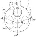
- Reference numeral 2 shown in FIG. 2Ais a transparent resin outer layer portion, and constitutes the most advanced portion of an endoscope resin tip part (hereinafter abbreviated as a tip part) 1.
- the transparent resin outer layer portion 2is formed of a first resin member and constitutes the tip portion surface of the tip portion 15.
- the first resin memberis a transparent resin for optical components having insulating properties.
- An opening 2m of the treatment instrument channel hole 30is provided at a predetermined position of the transparent resin outer layer portion 2 which is the front surface of the tip part 1. Further, illumination lens portions 2a and 2b and an observation lens portion 2c indicated by a two-dot chain line are provided at predetermined positions of the transparent resin outer layer portion 2. In this figure, two illumination lens portions 2a and 2b are provided with an observation lens portion 2c interposed therebetween. However, the number of illumination lens portions is not limited to two, and may be more or less.
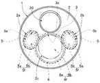
- an internal structure portion 3is provided on the inner surface side of the transparent resin outer layer portion 2 in the distal end portion 15.
- the internal structure unit 3includes through holes 3a, 3b, and 3c in which two illumination optical units 5 and an observation optical unit 6 are respectively disposed.
- Reference numeral 5fdenotes a front end surface of the illumination optical unit 5 and is disposed so as to face the illumination lens units 2a and 2b, respectively.
- Reference numeral 5ais a pipe
- reference numeral 5bis a light guide fiber.
- reference numeral 6fis a front end surface of the observation optical unit 6 and is disposed so as to face the observation lens unit 2c.
- Reference numeral 6adenotes a first lens frame
- reference numeral 6bdenotes an observation lens.
- the tip part 1is provided at the tip part 15.
- the tip component 1is a substantially cylindrical tip constituent member including a transparent resin outer layer portion 2, an internal structure portion 3, and a connecting portion 4.
- the internal structure part 3is formed of a second resin member different from the first resin member.
- the internal structure portion 3is provided in close contact with the inner surface 2 i of the transparent resin outer layer portion 2. And the internal structure part 3 is provided so that it may not be exposed to the front-end
- the second resin memberis an optically opaque, for example, black resin having insulating properties. That is, in this embodiment, the internal structure part 3 functions as a light shielding part.
- the transparent resin outer layer portion 2 and the internal structure portion 3are formed as a two-color molded product 7 by integral molding.
- connection part 4is a light shielding member, for example, an annular member made of stainless steel pipe.
- a circumferential step 4 ais provided on the outer peripheral surface on the proximal end side of the connecting portion 4.
- the circumferential step 4ahas a first step 4b and a second step 4c.
- the first step 4bis, for example, a piece step
- the second step 4cis a rubber step.
- the distal end side of the connecting portion 4is disposed on the outer peripheral surface of the proximal end side of the transparent resin outer layer portion 2 configured as the two-color molded product 7.
- the inner surface of the base end portion of the connecting portion 4is closely arranged by closing the boundary line 7 a between the transparent resin outer layer portion 2 and the internal structure portion 3 exposed at the base end surface of the two-color molded product 7.
- the connection part 4is integrally fixed to the two-color molded product 7 with an adhesive agent, for example, and comprises the front-end
- FIG. Therefore, the outer surface of the tip part 1is constituted by the transparent resin outer layer part 2 and the connecting part 4.
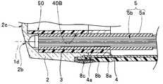
- the distal-end component 1is formed with a treatment instrument channel hole 30 that is a through hole, illumination optical holes 40A and 40B, and observation optical holes 50 that are blind holes.
- the treatment instrument channel hole 30, the illumination optical holes 40A and 40B, and the observation optical hole 50also serve as component fixing holes.
- the treatment instrument channel hole 30has a first shaft 1b parallel to the longitudinal axis 1a of the tip component 1, and is formed in the connecting portion 4 and the through hole 2h having the tip opening 2m formed in the transparent resin outer layer portion 2. It is comprised with the through-hole 4h1 for treatment.
- the first illumination optical hole 40Ais provided corresponding to the first illumination lens portion 2a, and has a second axis 1c parallel to the longitudinal axis 1a of the tip part 1.
- 40 A of 1st illumination optical holesare comprised by the 1st through-hole 3a which the internal structure part 3 has, and the 1st through-hole 4h2 for illumination optics formed in the connection part 4. As shown in FIG.
- the second illumination optical hole 40Bis provided corresponding to the second illumination lens portion 2b and has a third axis 1d parallel to the longitudinal axis 1a of the tip part 1.
- the second illumination optical hole 40 ⁇ / b> Bincludes a second through hole 3 b included in the internal structure portion 3 and an illumination optical second through hole 4 h ⁇ b> 3 formed in the connecting portion 4.
- the observation optical hole 50is provided corresponding to the observation lens portion 2 c and has a fourth axis 1 e parallel to the longitudinal axis 1 a of the tip part 1.
- the observation optical hole 50includes a third through hole 3 c included in the internal structure portion 3 and an observation optical through hole 4 h 3 formed in the connecting portion 4.
- the circumferential step portion 4ais provided with a bending portion set tip bending piece 8a that constitutes the bending portion 16 in the piece step portion, and the rubber step portion is provided in the rubber step portion.
- a bending rubber 8b that covers the bending portion set and constitutes the bending portion 16is disposed.
- Reference numeral 8cdenotes a bobbin adhesive fixing portion.
- the illumination optical unit 5includes a pipe 5a and a light guide fiber 5b, and the tip portion of the light guide fiber 5b is protected by the pipe 5a.
- a distal end portion of a tube cap 9awhich is one of components, is fixedly provided on the proximal end side in the treatment instrument channel hole 30.
- the distal end portion of the channel tube 9bis fitted and fixed to the proximal end portion of the tube base 9a.
- a treatment instrumentsuch as a biopsy needle is introduced into the channel tube 9b from the treatment instrument insertion port 20 of FIG. 1, and after passing through the tube base 9a and introduced into the treatment instrument channel hole 30, it is led out from the distal end opening 2m. Is done.
- the distal end portion of the observation optical unit 6which is one of the components and is an optical component is fixed in the observation optical hole 50.
- the observation optical unit 6mainly includes an observation lens 6b, an objective optical system 6c, an imaging device 6d, and the like.
- Reference numeral 6adenotes a first lens frame
- reference numeral 6edenotes a second lens frame
- reference numeral 6fdenotes an imaging frame.
- An observation lens 6bis arranged in the first lens frame 6a, and a plurality of types of optical lenses 6g, an interval ring (not shown), a diaphragm (not shown), etc. are arranged as optical members in the second lens frame 6e.
- the tip of the second lens frame 6eis fixed to the first lens frame 6a.
- An optical lens 6hwhich is an optical member, is disposed in the imaging frame 6f.
- the base end portion of the second lens frame 6eis fixed to the imaging frame 6f.
- the imaging device 6dis connected to the individual imaging element 6i such as a CCD or C-MOS, a cover glass 6k disposed in front of the imaging surface, a circuit board 6n on which a plurality of electronic components 6m are mounted, and the circuit board 6n. And a signal cable (not shown) in which a plurality of signal lines 6p are grouped.
- the individual imaging element 6isuch as a CCD or C-MOS
- a cover glass 6kdisposed in front of the imaging surface
- a circuit board 6n on which a plurality of electronic components 6m are mountedand the circuit board 6n.
- a signal cable(not shown) in which a plurality of signal lines 6p are grouped.
- the illumination lightwhen irradiation light is emitted from a light source device (not shown), the illumination light is transmitted by the light guide fiber 5b provided in the endoscope 10. And illumination light is irradiated from the illumination optical part 5 each arrange
- the illumination light irradiated from the front end side of the illumination optical unit 5is diffused by the concave portions provided on the lens back surfaces of the illumination lens units 2a and 2b, and is transmitted through the transparent transparent resin outer layer unit 2 to illuminate the lens. Irradiated into the body cavity from the lens surfaces of the parts 2a and 2b, the observation site is illuminated with an appropriate light distribution.
- the optical image of the observation site illuminated by the illumination lightpasses through the transparent transparent resin outer layer 2 from the lens surface of the observation lens unit 2c, passes through the lens back surface, and enters the observation optical unit 6.
- the imageis picked up by the image pickup device 6d.
- the intended optical performanceis realized, and a good endoscopic image is displayed on the screen of a display device (not shown). Then, the endoscope 10 after use is autoclaved.
- the tip part 15 of the insertion part 11is provided with a tip part 1 in which the connecting part 4 is integrally fixed to a two-color molded product 7 in which the transparent resin outer layer part 2 and the internal structure part 3 are formed in two colors. ing. And the outer surface of the front-end
- tip component 1is comprised by the transparent resin outer-layer part 2 and the connection part 4 in which the boundary of the 1st resin member and 2nd resin member by two-color molding does not exist.
- the illumination light of the illumination optical unit 5 disposed in the through holes 3a and 3b of the internal structure portion 3is emitted to the outside through the internal structure portion 3. Can be reliably prevented.
- the internal structure portion 3has the through holes 3a, 3b, and 3c as shown in FIG. 2B.
- the internal structure portion 3A having the fourth through hole 3dmay be used.
- the fourth through hole 3dis a treatment instrument insertion through hole.
- the external shape of the internal structure part 3is not limited to the embodiment described above. Other configurations are the same as those of the above-described embodiment, and the same members are denoted by the same reference numerals and description thereof is omitted.
- the treatment instrument channel hole 30Ais formed in the through hole 2h having the tip opening 2m formed in the transparent resin outer layer portion 2, the fourth through hole 3d in the internal structure portion 3A, and the connecting portion 4. And the treatment through-hole 4h1. According to this configuration, the same operations and effects as those of the above-described embodiment can be obtained.
Landscapes
- Health & Medical Sciences (AREA)
- Life Sciences & Earth Sciences (AREA)
- Physics & Mathematics (AREA)
- Surgery (AREA)
- Engineering & Computer Science (AREA)
- Optics & Photonics (AREA)
- Medical Informatics (AREA)
- General Health & Medical Sciences (AREA)
- Pathology (AREA)
- Nuclear Medicine, Radiotherapy & Molecular Imaging (AREA)
- Biomedical Technology (AREA)
- Heart & Thoracic Surgery (AREA)
- Veterinary Medicine (AREA)
- Molecular Biology (AREA)
- Animal Behavior & Ethology (AREA)
- Radiology & Medical Imaging (AREA)
- Public Health (AREA)
- Biophysics (AREA)
- Astronomy & Astrophysics (AREA)
- General Physics & Mathematics (AREA)
- Manufacturing & Machinery (AREA)
- Multimedia (AREA)
- Urology & Nephrology (AREA)
- Endoscopes (AREA)
- Instruments For Viewing The Inside Of Hollow Bodies (AREA)
Abstract
Description
Translated fromJapanese本発明は、内視鏡先端部に設けられる二種類の樹脂部材を一体にした内視鏡用樹脂製先端部品に関する。The present invention relates to an endoscope resin tip part in which two kinds of resin members provided at an endoscope tip part are integrated.
内視鏡は、医療分野及び工業分野で広く利用されている。内視鏡による診断の対象、或いは、観察の対象は、生体内、プラント内、等である。したがって、内視鏡装置においては、診断対象、或いは、観察対象を照明する光源が必要である。Endoscopes are widely used in the medical and industrial fields. The object of diagnosis by the endoscope or the object of observation is in a living body, in a plant, or the like. Therefore, in the endoscope apparatus, a light source that illuminates the diagnosis target or the observation target is necessary.
一般的な内視鏡装置は、内視鏡と、内視鏡外部装置としての光源装置と、を備えている。光源装置は、照明光を出射するランプ或いは発光素子等の発光源を内蔵している。
発光源から出射された照明光は、内視鏡に設けられたライトガイドファイバによって伝送され、挿入部先端に設けられた照明窓を通過して観察対象を照明する。A general endoscope apparatus includes an endoscope and a light source device as an endoscope external device. The light source device incorporates a light source such as a lamp or a light emitting element that emits illumination light.
Illumination light emitted from the light source is transmitted by a light guide fiber provided in the endoscope, and passes through an illumination window provided at the distal end of the insertion portion to illuminate the observation target.
照明窓は、一般に、絶縁性を有する先端カバーに形成された貫通孔に水密に固定されている。そして、照明窓を固定した先端カバーは、挿入部の先端部を構成するステンレス鋼等の金属製の先端硬性部に一体固定される。The illumination window is generally fixed in a watertight manner to a through hole formed in the tip cover having an insulating property. And the front-end | tip cover which fixed the illumination window is integrally fixed to metal front-end | tip hard parts, such as stainless steel which comprises the front-end | tip part of an insertion part.
日本国再表2011-111242号公報には、内視鏡の観察光学系、及びまたは、カメラの撮像光学系等に用いられる光学素子と、この光学素子を支持する支持部材と、を一体化して成形する樹脂成形品の製造方法、樹脂成形品が開示されている。
日本国再表2011-111242号公報の図27、図35等には、照明レンズを光学部品用の樹脂とし、支持部材である先端部本体を光学的に不透明な、例えば黒色の樹脂とした二色成形品が示されている。この二色成形品によれば、内視鏡の挿入部の径を太くすることなく、挿入部の先端部を構成することができる。In Japanese National Table No. 2011-111242, an optical element used in an observation optical system of an endoscope and / or an imaging optical system of a camera and a support member that supports the optical element are integrated. A method for producing a resin molded product to be molded and a resin molded product are disclosed.
27, 35, etc. of Japanese National Table No. 2011-111242, the illumination lens is made of resin for optical components, and the tip body as a support member is made of optically opaque, for example, black resin. A color molded product is shown. According to this two-color molded product, the distal end portion of the insertion portion can be configured without increasing the diameter of the insertion portion of the endoscope.
しかしながら、前述した内視鏡の挿入部先端部を構成する二色成形品は、照明レンズと先端部本体との境界、言い替えれば、光学部品用の透明樹脂と光学的に不透明な樹脂との境界が外観に露出している。この境界は、微少な溝(ノッチとも記載する)であるが、内視鏡を繰り返し高圧高温蒸気滅菌(オートクレーブ滅菌とも記載する)した際、このノッチがクラック発生の起点になるおそれがある。However, the above-described two-color molded product constituting the distal end portion of the insertion portion of the endoscope has the boundary between the illumination lens and the distal end portion body, in other words, the boundary between the transparent resin for optical components and the optically opaque resin. Is exposed to the appearance. Although this boundary is a minute groove (also described as a notch), when the endoscope is repeatedly subjected to high-pressure high-temperature steam sterilization (also referred to as autoclave sterilization), this notch may become a starting point of crack generation.
本発明は上記事情に鑑みてなされたものであり、光学部品用の透明樹脂と該透明樹脂とは異なる樹脂とを一体に成形して挿入部の先端部に配設するのに適した内視鏡用樹脂製先端部品を提供することを目的にしている。The present invention has been made in view of the above circumstances, and is an internal view suitable for integrally forming a transparent resin for optical components and a resin different from the transparent resin and disposing them at the distal end of the insertion portion. The object is to provide resin-made tip parts for mirrors.
本発明の一態様の内視鏡用樹脂製先端部品は、透明な第1樹脂部材で形成されて挿入部の先端部表面を構成する透明樹脂外層部と、前記透明樹脂外層部の内面に密着して設けられる前記第1樹脂部材とは異なる第2樹脂部材で形成される内部構造部と、前記内部構造部に設けられ、前記挿入部内に配置される部品の先端側端部が配設される複数の部品固定孔と、前記透明樹脂外層部に設けられ、前記挿入部内に配置された光学部品の先端側端部が部品固定孔に配設されて該光学部品の先端面に対向して設けられるレンズ部と、を具備している。An endoscope resin tip part of one aspect of the present invention is in close contact with an inner surface of a transparent resin outer layer portion formed of a transparent first resin member and constituting a tip portion surface of an insertion portion, and the transparent resin outer layer portion An internal structure portion formed of a second resin member different from the first resin member provided, and a tip side end portion of a component provided in the internal structure portion and disposed in the insertion portion. A plurality of component fixing holes and an end portion on the front end side of the optical component provided in the transparent resin outer layer portion and disposed in the insertion portion so as to face the front end surface of the optical component. And a lens unit to be provided.
本発明によれば、光学部品用の透明樹脂と該透明樹脂とは異なる樹脂とを一体成形した挿入部の先端部に配設するのに適した内視鏡用樹脂製先端部品を実現できる。According to the present invention, it is possible to realize an endoscope resin tip part suitable for being disposed at the tip part of an insertion part formed by integrally molding a transparent resin for optical parts and a resin different from the transparent resin.
以下、図面を参照して本発明の実施の形態を説明する。
なお、以下の説明に用いる各図において、各構成要素を図面上で認識可能な程度の大きさとするため、構成要素毎に縮尺を異ならせてあるものもある。また、本発明は、これらの図に記載された構成要素の数量、構成要素の形状、構成要素の大きさの比率、及び各構成要素の相対的な位置関係のみに限定されるものではない。Embodiments of the present invention will be described below with reference to the drawings.
In each drawing used in the following description, the scale of each component may be different in order to make each component large enough to be recognized on the drawing. Further, the present invention is not limited only to the number of components described in these drawings, the shape of the components, the ratio of the sizes of the components, and the relative positional relationship between the components.
図1に示す内視鏡10は、例えば、腎盂尿管鏡であって、挿入部11と、操作部12と、接眼部13と、を設けて主に構成されている。接眼部13は、操作部12の基端側に設けられている。
符号14は、ユニバーサルコードであり、ユニバーサルコード14の接続コネクタ14cは、操作部12の側部に設けられたライトガイド接続口(不図示)に着脱自在である。An
挿入部11は、先端側から順に、硬質な先端部15、上下方向に湾曲するように構成され湾曲部16、及び可撓性を備えたチューブ体である可撓管部17を連設して構成されている。The
可撓管部17の基端側には予め定めた弾性力を有する折れ止め部18が設けられている。折れ止め部18は、可撓管部17の基端部を覆うように設けられて該可撓管部17の座屈を防止すると共に、当該可撓管部17と操作部12の先端側との水密を保持している。A
操作部12には、漏水検知口金19、処置具挿通口20、及び湾曲操作レバー21等が設けられている。湾曲操作レバー21は、回動自在であって、該レバー21の回動操作に伴って、湾曲ワイヤー(不図示)が牽引弛緩されることによって、湾曲部16が上下の2方向に湾曲する。The
なお、湾曲部16を湾曲ワイヤーの牽引弛緩によって湾曲動作する能動湾曲部と、外力を受けることによって湾曲する受動湾曲部とを設けて構成するようにしてもよい。また、内視鏡10は、腎盂尿管鏡に限定されるものでは無い。In addition, you may make it comprise the
図2Aに示す符号2は透明樹脂外層部であって、内視鏡用樹脂製先端部品(以下、先端部品と略記する)1の最先端部を構成する。透明樹脂外層部2は、第1樹脂部材で形成されており、先端部15の先端部表面を構成する。第1樹脂部材は、絶縁性を有する光学部品用の透明樹脂である。
先端部品1の正面である透明樹脂外層部2の予め定めた位置には、処置具チャンネル孔30の開口2mが設けられている。また、透明樹脂外層部2の予め定めた位置には、二点鎖線に示す照明用レンズ部2a、2bと、観察用レンズ部2cと、が設けられている。
本図においては、観察用レンズ部2cを挟んで2つの照明用レンズ部2a、2bを設ける構成としている。しかし、照明用レンズ部の数は、2つに限定されるものでは無くそれ以上、あるいは、それ以下であってもよい。An opening 2m of the treatment
In this figure, two
図2Bに示すように先端部15内である透明樹脂外層部2の内面側には内部構造部3が設けられている。内部構造部3は、2つの照明光学部5、および、観察光学部6がそれぞれ配設される貫通孔3a、3b、3cを有している。
符号5fは、照明光学部5の先端面であり、照明用レンズ部2a、2bにそれぞれ対向するように配置されている。符号5aはパイプであり、符号5bはライトガイドファイバである。
これに対して、符号6fは、観察光学部6の先端面であり、観察用レンズ部2cに対向するように配置されている。符号6aは第1レンズ枠であり、符号6bは観察レンズである。As shown in FIG. 2B, an
On the other hand,
図3、図4に示すように先端部15には先端部品1が設けられている。
先端部品1は、図5A、図5Bに示すように透明樹脂外層部2と、内部構造部3と、連結部4と、を備えた略円筒形状の先端構成部材である。As shown in FIGS. 3 and 4, the
As shown in FIGS. 5A and 5B, the
内部構造部3は、第1樹脂部材とは異なる第2樹脂部材で形成されている。内部構造部3は、透明樹脂外層部2の内面2iに密着して設けられている。そして、内部構造部3は、先端部15の先端部表面に露出することが無いように設けられている。
第2樹脂部材は、絶縁性を有する光学的に不透明な、例えば黒色の樹脂である。すなわち、本実施形態において、内部構造部3は、遮光部として機能する。
透明樹脂外層部2と内部構造部3とは、一体成型によって二色成形品7として形成される。The
The second resin member is an optically opaque, for example, black resin having insulating properties. That is, in this embodiment, the
The transparent resin
連結部4は、遮光部材であって、例えばステンレスパイプ製の環状部材である。
連結部4の基端側外周面には周状段部4aが設けられている。周状段部4aは、第1段部4bと、第2段部4cと、を有している。第1段部4bは、例えば駒用段部であり、第2段部4cはゴム用段部である。The
A
連結部4の先端側は、二色成形品7として構成された透明樹脂外層部2の基端側外周面に配置される。この配置状態において、連結部4の基端部内面は、二色成形品7の基端面で露出する透明樹脂外層部2と内部構造部3との境界線7aを塞いで密着配置される。
そして、連結部4は、例えば接着剤によって二色成形品7に一体固定されて先端部品1を構成する。したがって、先端部品1の外表面は、透明樹脂外層部2と連結部4とによって構成される。The distal end side of the connecting
And the
先端部品1には、貫通孔である処置具チャンネル孔30と、止まり穴である照明光学用穴40A、40B及び観察光学用穴50と、が形成されている。
処置具チャンネル孔30、照明光学用穴40A、40B、および、観察光学用穴50は、部品固定孔を兼用する。The distal-
The treatment
処置具チャンネル孔30は、先端部品1の長手軸1aに平行な第1軸1bを有し、透明樹脂外層部2に形成された先端開口2mを有する貫通孔2hと連結部4に形成された処置用貫通孔4h1とで構成される。The treatment
第1照明光学用穴40Aは、第1照明用レンズ部2aに対応して設けられ、先端部品1の長手軸1aに平行な第2軸1cを有する。第1照明光学用穴40Aは、内部構造部3が有する第1貫通孔3aと連結部4に形成された照明光学用第1貫通孔4h2とで構成される。The first illumination
第2照明光学用穴40Bは、第2照明用レンズ部2bに対応して設けられ、先端部品1の長手軸1aに平行な第3軸1dを有する。第2照明光学用穴40Bは、内部構造部3が有する第2貫通孔3bと連結部4に形成された照明光学用第2貫通孔4h3とで構成される。The second illumination
観察光学用穴50は、観察用レンズ部2cに対応して設けられ、先端部品1の長手軸1aに平行な第4軸1eを有する。観察光学用穴50は、内部構造部3が有する第3貫通孔3cと連結部4に形成された観察光学用貫通孔4h3とで構成されている。The observation
図3、図4に示すように周状段部4aには駒用段部には湾曲部16を構成する図示されていない湾曲部組の先端湾曲駒8aが配置され、ゴム用段部には湾曲部組を被覆して湾曲部16を構成する湾曲ゴム8bが配置されている。
符号8cは、糸巻接着固定部である。As shown in FIGS. 3 and 4, the
図4に示すように照明光学用穴40A、40Bには部品の一つであって光学部品である照明光学部5の先端側部分がそれぞれ固設される。
照明光学部5は、パイプ5aと、ライトガイドファイバ5bと、を有して構成され、ライトガイドファイバ5bの先端部分は、パイプ5aによって保護されている。As shown in FIG. 4, in the illumination
The illumination
一方、図3に示すように処置具チャンネル孔30内の基端側には部品の一つであるチューブ用口金9aの先端部が固設されている。チューブ用口金9aの基端部にはチャンネルチューブ9bの先端部が外嵌固定されている。
生検針等の処置具は、図1の処置具挿通口20からチャンネルチューブ9b内に導入され、チューブ用口金9a内を通過して処置具チャンネル孔30に導入された後、先端開口2mから導出される。On the other hand, as shown in FIG. 3, a distal end portion of a
A treatment instrument such as a biopsy needle is introduced into the
観察光学用穴50には部品の一つであって光学部品である観察光学部6の先端側部分が固設される。
観察光学部6は、観察レンズ6b、対物光学系6c、撮像装置6d等を有して主に構成される。符号6aは第1レンズ枠、符号6eは第2レンズ枠、符号6fは撮像枠である。The distal end portion of the observation
The observation
第1レンズ枠6a内には観察レンズ6bが配置され、第2レンズ枠6e内には、光学部材として複数種類の光学レンズ6g、間隔環(不図示)、絞り(不図示)等が配設されている。第2レンズ枠6eの先端部は、第1レンズ枠6aに固設される。撮像枠6fには、光学部材である光学レンズ6h等が配設されている。第2レンズ枠6eの基端部は、撮像枠6fに固設される。An
撮像装置6dは、CCD、C-MOS等の個体撮像素子6iと、撮像面の前面に配置されるカバーガラス6kと、複数の電子部品6mを搭載した回路基板6nと、回路基板6nに接続される複数の信号線6pを一纏めにした信号ケーブル(不図示)等を有して構成されている。The
上述のように構成された内視鏡10によれば、図示しない光源装置から照射光が出射されると、照明光は、内視鏡10に設けられたライトガイドファイバ5bによって伝送される。そして、照明光は、挿入部11の先端部15を構成する先端部品1の照明光学用穴40A、40Bにそれぞれ配設された照明光学部5から照射される。According to the
照明光学部5の先端側からそれぞれ照射された照明光は、照明用レンズ部2a、2bのレンズ裏面に設けられた凹部によって拡散されて透明な透明樹脂外層部2内を透過して照明用レンズ部2a、2bのレンズ表面から体腔内に照射されて観察部位を適切な配光で照らす。The illumination light irradiated from the front end side of the illumination
この結果、照明光によって照らされた観察部位の光学像は、観察用レンズ部2cのレンズ表面から透明な透明樹脂外層部2内を透過してレンズ裏面を通過して観察光学部6に入射して撮像装置6dによって撮像される。
このことによって、意図した光学性能が実現されて、良好な内視鏡画像が図示しない表示装置の画面上に表示される。
そして、使用後の内視鏡10は、オートクレーブ滅菌される。As a result, the optical image of the observation site illuminated by the illumination light passes through the transparent transparent resin
As a result, the intended optical performance is realized, and a good endoscopic image is displayed on the screen of a display device (not shown).
Then, the
本発明において挿入部11の先端部15には透明樹脂外層部2と、内部構造部3と、を二色形成した二色成形品7に連結部4を一体固定にした先端部品1が設けられている。そして、先端部品1の外表面は、二色成形による第1樹脂部材と第2樹脂部材との境界が存在しない透明樹脂外層部2と、連結部4と、によって構成されている。In the present invention, the
この構成によれば、先端部品1の外表面に、二色成形品7の透明樹脂外層部2だけを配設することができる。このため、オートクレーブ滅菌を繰り返し行った際に、微少な溝であるノッチを起点にクラックが発生する不具合が解消される。According to this configuration, only the transparent resin
また、内部構造部3を遮光部としたことによって、内部構造部3の貫通孔3a、3b内に配設した照明光学部5の照明光が内部構造部3を介して外部に出射されることを確実に防止することができる。Further, by using the
なお、上述した実施形態において、内部構造部3は、図2Bに示したように貫通孔3a、3b、3cを有するとしている。しかし、図6、図7に示すように貫通孔3a、3b、3cに加えて、第4貫通孔3dを有する内部構造部3Aであってもよい。
第4貫通孔3dは、処置具挿通用貫通孔である。
内部構造部3の外形形状は、上述した実施形態に限定されるものでは無い。その他の構成は上述した実施形態と同様であり、同部材には同符号を付して説明を省略する。In the above-described embodiment, the
The fourth through
The external shape of the
本実施形態において、処置具チャンネル孔30Aは、透明樹脂外層部2に形成された先端開口2mを有する貫通孔2hと、内部構造部3Aが有する第4貫通孔3dと、連結部4に形成された処置用貫通孔4h1と、で構成される。
この構成によれば、上述した実施形態と同様の作用及び効果を得ることができる。In the present embodiment, the treatment
According to this configuration, the same operations and effects as those of the above-described embodiment can be obtained.
尚、本発明は、以上述べた実施形態のみに限定されるものではなく、発明の要旨を逸脱しない範囲で種々変形実施可能である。The present invention is not limited to the embodiments described above, and various modifications can be made without departing from the spirit of the invention.
本出願は、2015年5月8日に日本国に出願された特願2015-095742号を優先権主張の基礎として出願するものであり、上記の内容は、本願明細書、請求の範囲、および図面に引用されたものである。This application is filed on the basis of the priority claim of Japanese Patent Application No. 2015-095742 filed in Japan on May 8, 2015, and the above-mentioned contents include the present specification, claims, and It is cited in the drawing.
Claims (4)
Translated fromJapanese前記透明樹脂外層部の内面に密着して設けられる前記第1樹脂部材とは異なる第2樹脂部材で形成される内部構造部と、
前記内部構造部に設けられ、前記挿入部内に配置される部品の先端側端部が配設される複数の部品固定孔と、
前記透明樹脂外層部に設けられ、前記挿入部内に配置された光学部品の先端側端部が部品固定孔に配設されて該光学部品の先端面に対向して設けられるレンズ部と、
を具備することを特徴とする内視鏡用樹脂製先端部品。A transparent resin outer layer part that is formed of a transparent first resin member and constitutes the tip part surface of the insertion part;
An internal structure portion formed of a second resin member different from the first resin member provided in close contact with the inner surface of the transparent resin outer layer portion;
A plurality of component fixing holes provided in the internal structure portion, in which the tip side end portions of the components disposed in the insertion portion are disposed;
A lens portion that is provided in the transparent resin outer layer portion and is disposed in a component fixing hole at a front end side of the optical component that is disposed in the insertion portion and is opposed to the front end surface of the optical component;
A resin-made tip part for an endoscope, comprising:
前記二色成形品の透明樹脂外層部の基端側外周面に先端部が配設される連結部と、
を具備することを特徴とする請求項1に記載の内視鏡用樹脂製先端部品。A two-color molded product composed of the transparent resin outer layer part and the inner structure part serving as a light shielding part,
A connecting portion having a tip portion disposed on the outer peripheral surface of the base end side of the transparent resin outer layer portion of the two-color molded product;
The resin-made tip part for endoscopes according to claim 1 characterized by comprising.
Priority Applications (4)
| Application Number | Priority Date | Filing Date | Title |
|---|---|---|---|
| JP2016557347AJP6072393B1 (en) | 2015-05-08 | 2016-04-04 | Resin tip parts for endoscope |
| EP16792449.7AEP3207852B1 (en) | 2015-05-08 | 2016-04-04 | Resin distal end component for endoscope |
| CN201680003563.3ACN107105978A (en) | 2015-05-08 | 2016-04-04 | Endoscope-use resin-made front end component |
| US15/597,660US20170245734A1 (en) | 2015-05-08 | 2017-05-17 | Resin distal end component for endoscope |
Applications Claiming Priority (2)
| Application Number | Priority Date | Filing Date | Title |
|---|---|---|---|
| JP2015-095742 | 2015-05-08 | ||
| JP2015095742 | 2015-05-08 |
Related Child Applications (1)
| Application Number | Title | Priority Date | Filing Date |
|---|---|---|---|
| US15/597,660ContinuationUS20170245734A1 (en) | 2015-05-08 | 2017-05-17 | Resin distal end component for endoscope |
Publications (1)
| Publication Number | Publication Date |
|---|---|
| WO2016181724A1true WO2016181724A1 (en) | 2016-11-17 |
Family
ID=57247916
Family Applications (1)
| Application Number | Title | Priority Date | Filing Date |
|---|---|---|---|
| PCT/JP2016/061029CeasedWO2016181724A1 (en) | 2015-05-08 | 2016-04-04 | Resin distal end component for endoscope |
Country Status (5)
| Country | Link |
|---|---|
| US (1) | US20170245734A1 (en) |
| EP (1) | EP3207852B1 (en) |
| JP (1) | JP6072393B1 (en) |
| CN (1) | CN107105978A (en) |
| WO (1) | WO2016181724A1 (en) |
Cited By (3)
| Publication number | Priority date | Publication date | Assignee | Title |
|---|---|---|---|---|
| WO2019234982A1 (en)* | 2018-06-05 | 2019-12-12 | オリンパス株式会社 | Endoscope |
| US20210059505A1 (en)* | 2018-06-06 | 2021-03-04 | Olympus Corporation | Endoscope bonding structure and endoscope |
| JP2022505913A (en)* | 2018-10-26 | 2022-01-14 | Hoya株式会社 | Endoscope tips and endoscopes with housing elements made of translucent material |
Families Citing this family (20)
| Publication number | Priority date | Publication date | Assignee | Title |
|---|---|---|---|---|
| US20180317755A1 (en)* | 2015-07-10 | 2018-11-08 | Sharp Kabushiki Kaisha | In-body image capturing device and in-body monitoring camera system |
| EP3539447A1 (en)* | 2018-03-14 | 2019-09-18 | Ambu A/S | A tip part for a vision device |
| EP3539446A1 (en)* | 2018-03-14 | 2019-09-18 | Ambu A/S | A tip part for a vision device |
| EP3539450B1 (en)* | 2018-03-14 | 2024-01-24 | Ambu A/S | A tip part for a vision device |
| EP3539445A1 (en) | 2018-03-14 | 2019-09-18 | Ambu A/S | Method for manufacturing a tip housing |
| CN112312818B (en) | 2018-06-28 | 2025-01-21 | 波士顿科学国际有限公司 | Medical device packaging assembly and method thereof |
| US11311184B2 (en) | 2018-08-24 | 2022-04-26 | Ambu A/S | Tip part for a vision device |
| EP3613326B1 (en) | 2018-08-24 | 2023-09-20 | Ambu A/S | A tip part for a vision device |
| EP3613327A1 (en) | 2018-08-24 | 2020-02-26 | Ambu A/S | A tip part for a vision device |
| EP3708061A1 (en) | 2019-03-14 | 2020-09-16 | Ambu A/S | A tip part for an endoscope |
| CN110251057A (en)* | 2019-07-04 | 2019-09-20 | 苏州新光维医疗科技有限公司 | endoscope |
| US11794389B2 (en)* | 2019-09-06 | 2023-10-24 | Ambu A/S | Tip part assembly for an endoscope |
| EP3858217A1 (en) | 2020-01-28 | 2021-08-04 | Ambu A/S | A tip part of an endoscope |
| JP7398974B2 (en)* | 2020-01-30 | 2023-12-15 | オリンパス株式会社 | Endoscope tip frame and endoscope |
| US12268368B2 (en) | 2020-04-30 | 2025-04-08 | Ambu A/S | Medical visualisation device |
| CN114098588B (en)* | 2020-09-01 | 2025-08-12 | 宁波新跃医疗科技股份有限公司 | Binocular ureteroscope and manufacturing method thereof |
| EP3964116A1 (en) | 2020-09-02 | 2022-03-09 | Ambu A/S | Endoscope tip part |
| EP3991629A1 (en)* | 2020-10-30 | 2022-05-04 | Ambu A/S | An endoscope and a method for moulding transparent windows of an endoscope |
| EP4011270A1 (en) | 2020-12-08 | 2022-06-15 | Ambu A/S | Endoscope tip part with improved optical properties |
| US11867897B2 (en)* | 2021-07-06 | 2024-01-09 | Evident Corporation | Insertion assisting instrument and extraction method of insertion portion of endoscope |
Citations (3)
| Publication number | Priority date | Publication date | Assignee | Title |
|---|---|---|---|---|
| JP2003235787A (en)* | 2002-02-20 | 2003-08-26 | Pentax Corp | Endoscope apparatus and its illumination mechanism |
| JP2006255247A (en)* | 2005-03-18 | 2006-09-28 | Pentax Corp | Capsule endoscope |
| JP2009297420A (en)* | 2008-06-17 | 2009-12-24 | Fujinon Corp | Endoscope |
Family Cites Families (8)
| Publication number | Priority date | Publication date | Assignee | Title |
|---|---|---|---|---|
| US4841952A (en)* | 1986-11-06 | 1989-06-27 | Olympus Optical Co., Ltd. | Endoscope with an optical system |
| US7585275B2 (en)* | 2005-01-18 | 2009-09-08 | Hoya Corporation | Capsule endoscope |
| US7955255B2 (en)* | 2006-04-20 | 2011-06-07 | Boston Scientific Scimed, Inc. | Imaging assembly with transparent distal cap |
| JP4777482B2 (en)* | 2009-03-31 | 2011-09-21 | オリンパスメディカルシステムズ株式会社 | Endoscope |
| CN102791457A (en)* | 2010-03-09 | 2012-11-21 | 奥林巴斯株式会社 | Method for producing resin molded article, resin molded article for endoscope, endoscope using resin molded article, and apparatus for producing resin molded article |
| JP5871505B2 (en)* | 2011-07-29 | 2016-03-01 | キヤノン株式会社 | Printing apparatus and printing method |
| JP5298260B1 (en)* | 2011-10-12 | 2013-09-25 | オリンパスメディカルシステムズ株式会社 | Endoscope |
| CN103562770B (en)* | 2012-01-13 | 2016-06-29 | 奥林巴斯株式会社 | Endoscope tip component and endoscope |
- 2016
- 2016-04-04WOPCT/JP2016/061029patent/WO2016181724A1/ennot_activeCeased
- 2016-04-04CNCN201680003563.3Apatent/CN107105978A/enactivePending
- 2016-04-04JPJP2016557347Apatent/JP6072393B1/enactiveActive
- 2016-04-04EPEP16792449.7Apatent/EP3207852B1/enactiveActive
- 2017
- 2017-05-17USUS15/597,660patent/US20170245734A1/ennot_activeAbandoned
Patent Citations (3)
| Publication number | Priority date | Publication date | Assignee | Title |
|---|---|---|---|---|
| JP2003235787A (en)* | 2002-02-20 | 2003-08-26 | Pentax Corp | Endoscope apparatus and its illumination mechanism |
| JP2006255247A (en)* | 2005-03-18 | 2006-09-28 | Pentax Corp | Capsule endoscope |
| JP2009297420A (en)* | 2008-06-17 | 2009-12-24 | Fujinon Corp | Endoscope |
Non-Patent Citations (1)
| Title |
|---|
| See also references ofEP3207852A4* |
Cited By (6)
| Publication number | Priority date | Publication date | Assignee | Title |
|---|---|---|---|---|
| WO2019234982A1 (en)* | 2018-06-05 | 2019-12-12 | オリンパス株式会社 | Endoscope |
| US20210059505A1 (en)* | 2018-06-06 | 2021-03-04 | Olympus Corporation | Endoscope bonding structure and endoscope |
| US12089808B2 (en)* | 2018-06-06 | 2024-09-17 | Olympus Corporation | Endoscope bonding structure and endoscope |
| JP2022505913A (en)* | 2018-10-26 | 2022-01-14 | Hoya株式会社 | Endoscope tips and endoscopes with housing elements made of translucent material |
| JP7418425B2 (en) | 2018-10-26 | 2024-01-19 | Hoya株式会社 | Endoscope tip and endoscope with housing element made from translucent material |
| US12178394B2 (en) | 2018-10-26 | 2024-12-31 | Hoya Corporation | Endoscope head comprising a housing element made from transparent material |
Also Published As
| Publication number | Publication date |
|---|---|
| EP3207852A4 (en) | 2018-07-25 |
| EP3207852B1 (en) | 2019-06-05 |
| EP3207852A1 (en) | 2017-08-23 |
| CN107105978A (en) | 2017-08-29 |
| JPWO2016181724A1 (en) | 2017-05-25 |
| US20170245734A1 (en) | 2017-08-31 |
| JP6072393B1 (en) | 2017-02-01 |
Similar Documents
| Publication | Publication Date | Title |
|---|---|---|
| JP6072393B1 (en) | Resin tip parts for endoscope | |
| JP5524609B2 (en) | Endoscope protector and endoscope corresponding thereto | |
| JP5977911B1 (en) | Endoscope | |
| BRPI0615651A2 (en) | disposable endoscope cap | |
| US20200029791A1 (en) | Endoscope | |
| US10498940B2 (en) | Endoscope | |
| JP5646356B2 (en) | Endoscope | |
| WO2014188787A1 (en) | Endoscope tip structure and endoscope | |
| CN110996749A (en) | 3D video endoscope | |
| JP2016202830A (en) | Endoscope distal end portion and endoscope | |
| JP2015000267A (en) | Endoscope and endoscope system | |
| KR20180074858A (en) | Disposable Separate Endoscope Including Plastic Optical Fiber | |
| JP5851661B1 (en) | Optical transceiver unit | |
| US9537574B2 (en) | Optical transmitting and receiving unit | |
| US8754933B2 (en) | Miniature photographic apparatus | |
| JP2005124776A (en) | Endoscope and endoscope system | |
| US10197785B2 (en) | Inspection device for image pickup apparatus | |
| JPWO2015056568A1 (en) | Endoscope | |
| JP6671967B2 (en) | Endoscope | |
| JP2017209235A (en) | Endoscope | |
| KR20170022575A (en) | Endoscopy apparatus | |
| JP6292560B2 (en) | Endoscope | |
| CN206934080U (en) | Endoscope distal end adapter | |
| JP4914623B2 (en) | Endoscope | |
| JP2001275959A (en) | Finger mounting endoscopic instrument |
Legal Events
| Date | Code | Title | Description |
|---|---|---|---|
| ENP | Entry into the national phase | Ref document number:2016557347 Country of ref document:JP Kind code of ref document:A | |
| 121 | Ep: the epo has been informed by wipo that ep was designated in this application | Ref document number:16792449 Country of ref document:EP Kind code of ref document:A1 | |
| REEP | Request for entry into the european phase | Ref document number:2016792449 Country of ref document:EP | |
| NENP | Non-entry into the national phase | Ref country code:DE |