WO2016166828A1 - Operating part for bendable treatment tool - Google Patents
Operating part for bendable treatment toolDownload PDFInfo
- Publication number
- WO2016166828A1 WO2016166828A1PCT/JP2015/061563JP2015061563WWO2016166828A1WO 2016166828 A1WO2016166828 A1WO 2016166828A1JP 2015061563 WJP2015061563 WJP 2015061563WWO 2016166828 A1WO2016166828 A1WO 2016166828A1
- Authority
- WO
- WIPO (PCT)
- Prior art keywords
- bending
- wire
- operation unit
- main body
- treatment tool
- Prior art date
- Legal status (The legal status is an assumption and is not a legal conclusion. Google has not performed a legal analysis and makes no representation as to the accuracy of the status listed.)
- Ceased
Links
Images


Classifications
- A—HUMAN NECESSITIES
- A61—MEDICAL OR VETERINARY SCIENCE; HYGIENE
- A61B—DIAGNOSIS; SURGERY; IDENTIFICATION
- A61B34/00—Computer-aided surgery; Manipulators or robots specially adapted for use in surgery
- A61B34/70—Manipulators specially adapted for use in surgery
- A61B34/71—Manipulators operated by drive cable mechanisms
- A—HUMAN NECESSITIES
- A61—MEDICAL OR VETERINARY SCIENCE; HYGIENE
- A61B—DIAGNOSIS; SURGERY; IDENTIFICATION
- A61B17/00—Surgical instruments, devices or methods
- A61B17/28—Surgical forceps
- A61B17/29—Forceps for use in minimally invasive surgery
- A—HUMAN NECESSITIES
- A61—MEDICAL OR VETERINARY SCIENCE; HYGIENE
- A61B—DIAGNOSIS; SURGERY; IDENTIFICATION
- A61B17/00—Surgical instruments, devices or methods
- A61B17/28—Surgical forceps
- A61B17/29—Forceps for use in minimally invasive surgery
- A61B17/2909—Handles
- A—HUMAN NECESSITIES
- A61—MEDICAL OR VETERINARY SCIENCE; HYGIENE
- A61B—DIAGNOSIS; SURGERY; IDENTIFICATION
- A61B17/00—Surgical instruments, devices or methods
- A61B17/28—Surgical forceps
- A61B17/29—Forceps for use in minimally invasive surgery
- A61B17/295—Forceps for use in minimally invasive surgery combined with cutting implements
- A—HUMAN NECESSITIES
- A61—MEDICAL OR VETERINARY SCIENCE; HYGIENE
- A61B—DIAGNOSIS; SURGERY; IDENTIFICATION
- A61B34/00—Computer-aided surgery; Manipulators or robots specially adapted for use in surgery
- A61B34/70—Manipulators specially adapted for use in surgery
- A61B34/74—Manipulators with manual electric input means
- A—HUMAN NECESSITIES
- A61—MEDICAL OR VETERINARY SCIENCE; HYGIENE
- A61B—DIAGNOSIS; SURGERY; IDENTIFICATION
- A61B17/00—Surgical instruments, devices or methods
- A61B17/00234—Surgical instruments, devices or methods for minimally invasive surgery
- A61B2017/00238—Type of minimally invasive operation
- A61B2017/00269—Type of minimally invasive operation endoscopic mucosal resection EMR
- A—HUMAN NECESSITIES
- A61—MEDICAL OR VETERINARY SCIENCE; HYGIENE
- A61B—DIAGNOSIS; SURGERY; IDENTIFICATION
- A61B17/00—Surgical instruments, devices or methods
- A61B17/00234—Surgical instruments, devices or methods for minimally invasive surgery
- A61B2017/00292—Surgical instruments, devices or methods for minimally invasive surgery mounted on or guided by flexible, e.g. catheter-like, means
- A61B2017/003—Steerable
- A61B2017/00318—Steering mechanisms
- A61B2017/00323—Cables or rods
- A—HUMAN NECESSITIES
- A61—MEDICAL OR VETERINARY SCIENCE; HYGIENE
- A61B—DIAGNOSIS; SURGERY; IDENTIFICATION
- A61B17/00—Surgical instruments, devices or methods
- A61B17/00234—Surgical instruments, devices or methods for minimally invasive surgery
- A61B2017/00292—Surgical instruments, devices or methods for minimally invasive surgery mounted on or guided by flexible, e.g. catheter-like, means
- A61B2017/0034—Surgical instruments, devices or methods for minimally invasive surgery mounted on or guided by flexible, e.g. catheter-like, means adapted to be inserted through a working channel of an endoscope
- A—HUMAN NECESSITIES
- A61—MEDICAL OR VETERINARY SCIENCE; HYGIENE
- A61B—DIAGNOSIS; SURGERY; IDENTIFICATION
- A61B17/00—Surgical instruments, devices or methods
- A61B2017/0042—Surgical instruments, devices or methods with special provisions for gripping
- A61B2017/00438—Surgical instruments, devices or methods with special provisions for gripping connectable to a finger
- A—HUMAN NECESSITIES
- A61—MEDICAL OR VETERINARY SCIENCE; HYGIENE
- A61B—DIAGNOSIS; SURGERY; IDENTIFICATION
- A61B17/00—Surgical instruments, devices or methods
- A61B2017/00982—General structural features
- A61B2017/00991—Telescopic means
- A—HUMAN NECESSITIES
- A61—MEDICAL OR VETERINARY SCIENCE; HYGIENE
- A61B—DIAGNOSIS; SURGERY; IDENTIFICATION
- A61B17/00—Surgical instruments, devices or methods
- A61B17/28—Surgical forceps
- A61B17/29—Forceps for use in minimally invasive surgery
- A61B2017/2901—Details of shaft
- A61B2017/2906—Multiple forceps
- A—HUMAN NECESSITIES
- A61—MEDICAL OR VETERINARY SCIENCE; HYGIENE
- A61B—DIAGNOSIS; SURGERY; IDENTIFICATION
- A61B17/00—Surgical instruments, devices or methods
- A61B17/28—Surgical forceps
- A61B17/29—Forceps for use in minimally invasive surgery
- A61B17/2909—Handles
- A61B2017/291—Handles the position of the handle being adjustable with respect to the shaft
- A—HUMAN NECESSITIES
- A61—MEDICAL OR VETERINARY SCIENCE; HYGIENE
- A61B—DIAGNOSIS; SURGERY; IDENTIFICATION
- A61B17/00—Surgical instruments, devices or methods
- A61B17/28—Surgical forceps
- A61B17/29—Forceps for use in minimally invasive surgery
- A61B2017/2926—Details of heads or jaws
- A61B2017/2927—Details of heads or jaws the angular position of the head being adjustable with respect to the shaft
- A61B2017/2929—Details of heads or jaws the angular position of the head being adjustable with respect to the shaft with a head rotatable about the longitudinal axis of the shaft
- A—HUMAN NECESSITIES
- A61—MEDICAL OR VETERINARY SCIENCE; HYGIENE
- A61B—DIAGNOSIS; SURGERY; IDENTIFICATION
- A61B90/00—Instruments, implements or accessories specially adapted for surgery or diagnosis and not covered by any of the groups A61B1/00 - A61B50/00, e.g. for luxation treatment or for protecting wound edges
- A61B90/50—Supports for surgical instruments, e.g. articulated arms
Definitions
- the present inventionrelates to an operation unit for operating a bendable bending treatment instrument to be inserted into a flexible endoscope, and more specifically, for inserting a treatment instrument attached to a treatment instrument channel of a flexible endoscope or a flexible endoscope. Insert the tube into the tube and reach the digestive tract such as the gastrointestinal tract from the mouth and anus together with the soft endoscope, and the distal end of the treatment tool such as a scalpel or forceps used to remove cancer such as epithelial cancer
- the present inventionrelates to a bending treatment instrument having an operation portion for a bending treatment instrument that can be freely bent independently of a mirror.
- ESDendoscopic submucosal dissection
- a flexible endoscopesuch as a stomach camera or colon camera is inserted through the mouth, anus, vagina, urethra, etc. that are originally present on the surface of the body, and the flexible endoscope reaches the abdominal cavity through the stomach or colon wall.
- NOTESNatural Orifice Transluminal Endoscopic Surgery: transluminal endoscopic surgery
- Transluminal endoscopic surgeryrepresented by such endoscopic submucosal dissection and dissection (ESD) is a treatment tool such as a forceps and a scalpel along with a soft endoscope from the mouth that originally exists on the surface of the body. Since it is inserted into the affected area and treated, the surface of the body is not damaged at all, and complications such as infection and adhesion of the abdominal wall as in normal surgery can be eliminated. Invasion to can be reduced.
- ESDendoscopic submucosal dissection and dissection
- a treatment instrument used for such transluminal endoscopic surgeryis inserted into a flexible endoscope and bent from a distal end of the flexible endoscope. It has a bent part that can be operated freely.
- a sheath wire portion that transmits a bending motion to the bending portion, an operation portion that operates the bending motion of the bending portion by pushing and pulling the sheath wire, and the likeare provided.
- the structure of the operation unitis known in which a control member having at least two degrees of freedom is attached to the rail, and the treatment instrument has multiple degrees of freedom.
- the bending treatment instrument described in Patent Document 1has an outer diameter of about 4.0 mm and is not sized to be inserted into the endoscope channel of the endoscope, so it can be safely passed from the mouth to the stomach through the esophagus. It could not be reached and could not be used in practice.
- the outer diameteris narrowed to a size that can be inserted into the endoscope channel so that it can be applied to the endoscopic submucosal dissection and ablation (ESD) described above, it can be flexed freely and appropriately grasped by a forceps or a knife. This has hindered the excision of this and has not yet achieved this.
- the endoscope channel of the flexible endoscopehas various diameters of about 3.8 mm, 3.2 mm, and 2.8 mm, but any shape has a small diameter.
- the bending treatment toolis inserted into the endoscope channel and used, so that the distance between the sheath and the wire is close, and the friction between the sheath and the wire is increased by the operation of the operation unit. Therefore, there is a problem that the operation power cannot be transmitted to the bent portion or the treatment instrument.
- the present inventionhas been made to solve such a problem, and specifically, an operation of a bending treatment instrument that can be inserted into an endoscope channel and used for smooth bending operation by an intuitive operation.
- the purposeis to provide a department.
- An operation unitthat solves the above-described problem is provided with a treatment tool at a distal end, and is connected to the treatment tool of a bending treatment tool that can be bent freely, and the device wire that operates the treatment tool, and the bending A plurality of bending wires for bending the treatment instrument are connected to each other to operate the treatment instrument and the bending treatment instrument.
- the operation section main bodyis guided through the device wire.
- a bending wire pulling portionthat is swingably assembled with respect to the guide portion, and the device wire is connected to the bending wire pulling portion.
- a grip partcapable of reciprocating in the axial direction.
- the bending wire pulling section and the guide sectioninclude a spherical recess formed in either the bending wire pulling section or the guide section, and the bending wire pulling section. It is preferable to provide an axis alignment mechanism in which a spherical convex portion formed on the other of the first portion and the guide portion is fitted.
- the operation unit main bodyis detachably attached to the fixed base via the fixed base connecting part.
- the operation unit main bodyis attached with rotating means for rotatably assembling the operation unit main body with respect to the fixing base connecting part, and the rotating means is attached to the fixing base connecting part. It is preferable to provide a fixed portion to be fixed.
- the fixed base connection unitincludes a holding unit that holds the operation unit main body in a longitudinal direction.
- the fixed base connection unitincludes a linear motion unit that guides the operation unit main body along an extending direction of the device wire.
- the operation unit main bodyincludes a twisting force relief mechanism that prevents twisting of the device wire and the bending wire in the circumferential direction.
- the twisting force relief mechanismincludes a twisting force relief mechanism main body through which the device wire and the bending wire are inserted, and the device with respect to the twisting force relief mechanism main body. It is preferable to provide a rotating body that is immovable in the insertion direction of the wire for bending and the bending wire and is rotatably assembled in the circumferential direction.
- the fixed base connection unitincludes a holding unit capable of press-fitting a cover body attached to the operation unit main body.
- the holding meansincludes a groove-like first mooring portion and a second mooring portion extending substantially orthogonal to the longitudinal direction.
- the operation unitis connected to the operation unit main body, the guide unit through which the device wire passes, and the bending wire is connected, and the bending wire pulling unit is swingably assembled to the guide unit.
- the device wireare connected to each other, and the grip wire that can reciprocate in the axial direction of the bending wire pulling portion is provided, so that the bending wire pulling portion can be operated like a joystick. Operation can be realized.
- the bending wire pulling portion and the guide portionare either a spherical recess formed in one of the bending wire pulling portion or the guide portion, and either the bending wire pulling portion or the guide portion. Since it has an axis alignment mechanism that fits the spherical convex part formed on the other side, the bending wire pulling part can be operated like a joystick, and it can be used for devices even when the bending wire pulling part is tilted. The device wire can be pulled smoothly without shifting the central axis of the wire.
- the operation unit main bodyis detachably attached to the fixed base via the fixed base connecting part, an intuitive operation can be realized with one hand.
- the operating section main bodyis provided with a rotating means for rotatably assembling the operating section main body with respect to the fixed base connecting section, it occurs when the bending treatment instrument is inserted into the endoscope channel.
- the operation portion main bodyis rotated via the rotating means so that the input direction of the operation portion matches the bending direction of the bending portion. Intuitive operation can be realized.
- the fixed base connecting portionincludes the holding means for holding the operation portion main body in the longitudinal direction, so that the operation portion main body can be rotated and reliably held.
- the operation unitcan be easily detached from the fixed base.
- the fixed base connecting portionincludes the linear motion means for guiding the operation portion main body along the extending direction of the device wire, so that the bending treatment device itself can be bent by pushing and pulling.
- the tip position of the treatment toolcan be easily adjusted.
- the operation unit main bodyincludes a twisting force relief mechanism that prevents twisting of the device wire and the bending wire in the circumferential direction, so that the device wire and the bending wire are inserted. Even when a twisting force is applied to the sheath, the twisting force is dispersed to prevent the operation of the device wire and the bending wire.
- the twisting force relief mechanismincludes the torsional force relief mechanism main body and the rotating body, so that the twisting force of the device wire and the bending wire is distributed with a simple configuration. Can be made.
- the fixing base connecting portionincludes the holding means capable of press-fitting the cover body attached to the operation portion main body, so that the operation can be easily performed only by press-fitting the cover body into the holding means.
- the body partcan be fixed.
- the holding meansincludes the groove-shaped first mooring portion and the second mooring portion extending substantially orthogonal to the longitudinal direction, so that the operation portion main body can be easily attached and detached. Is formed.
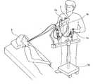
- FIG. 1Schematic for demonstrating the use condition of the bending treatment tool which concerns on 1st Embodiment.
- Itis a block diagram for demonstrating the structure of a sheath wire part, Comprising: (a) is a block diagram for demonstrating the structure of a sheath wire part, (b) is a wire for bending and a wire for devices It is a figure for demonstrating the modification of these, (c) is sectional drawing of the modification of a wire for bending and a wire for devices.
- the side view of the operation part of the bending treatment toolwhich concerns on 2nd Embodiment.
- FIG. 1is a schematic diagram for explaining a usage state of a bending treatment instrument according to the present embodiment
- FIG. 2is a schematic diagram for explaining an example of use of the bending treatment instrument according to the present embodiment
- FIG. 3is a side view for explaining the configuration of the forceps bending treatment instrument according to the present embodiment
- FIG. 4is a configuration diagram for explaining the configuration of the sheath wire part.
- FIG. 4is a configuration diagram for explaining a configuration of a sheath wire part
- (b)is a diagram for explaining a modification example of a bending wire and a device wire
- (c)is a bending wire.
- FIG. 5is a cross-sectional view of the operation portion of the bending treatment instrument according to the present embodiment
- FIG. 6is a cross-sectional view for explaining the internal structure of the operation portion
- 7 to 10are exploded views for explaining the structure of the rotating means. Is a perspective view of a fixing base connecting unit
- FIG. 12is a sectional view for illustrating the internal structure of the fixing base connection.
- the bending treatment toolincludes a forceps bending treatment tool 1 a having a forceps at the tip and a female bending treatment tool 1 b having an electric knife at the tip. .
- These bending treatment tools 1 a and 1 bare inserted into a treatment instrument insertion tube 2 b attached to the endoscope channel 2 a of the flexible endoscope 2 or the distal end of the flexible endoscope 2, and together with the flexible endoscope 2, the patient
- the affected part 3asuch as cancer in the abdominal cavity such as the digestive tract is diagnosed or excised from the mouth or anus of 3.
- the forceps bending treatment tool 1a and the female bending treatment tool 1bare individually bent independently of the flexible endoscope 2 so as to have at least two degrees of freedom, so that the viewpoint of the flexible endoscope 2 is fixed.
- the affected part 3acan be gripped and excised without any change, and a procedure with a high degree of freedom can be performed with a stable visual field.
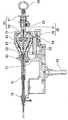
- a forceps bending treatment instrument 1ais attached to the distal end of a bending portion 4 having two degrees of freedom in the horizontal and vertical directions, and is assembled so as to be opened and closed by a device wire which will be described later.
- An operation unit 60that performs the bending operation of the bending unit 4 and the opening and closing operation of the forceps 30, and a sheath wire unit 5 including a plurality of wires that transmit the operation of the operation unit 60 and a sheath that passes through the wires.
- the scalpel bending treatment instrument 1bdiffers from the forceps bending treatment tool 1a in that it includes a bending portion and a sheath wire portion, and an electric scalpel is attached to the tip.
- the electric knifeis a member that is made of a conductive member and conducts high-frequency current to incise or cauterize the affected area.
- the tipis formed in a spherical shape or a hook shape.
- the protruding amountis configured to be appropriately adjustable by pushing and pulling a device wire 23 described later. Therefore, the specific description of the bending treatment tool will be made with respect to the forceps bending treatment tool 1a, and the detailed description of the female bending treatment tool 1b will be omitted.
- the sheath wire portion 5includes a plurality of inner sheaths 21 through which a plurality of bending wires 22 and device wires 23 are inserted, and an outer sheath 24 through which these inner sheaths 21 are inserted together.
- a liner blade 25 that adheres to the outer surface of the outer sheath 24 and a protective tube 26 that adheres to the outer surface of the liner blade 25are provided.
- the bending wire 22is a twisted wire obtained by winding a plurality of stainless steel wires, and the device wire 23 is thicker than the stainless steel wire used for the bending wire 22 and has a smaller number of stainless wires than the bending wire 22.
- the twisted wire 22is a twisted wire, and the bending wire 22 and the device wire 23 have substantially the same outer diameter.
- the bending wire 22is preferably a stranded wire formed by twisting 19 stainless steel wires
- the device wire 23is preferably a stranded wire formed by twisting 7 stainless steel wires.
- the bending wire 22 and the device wire 23are welded with a swaging wire 28 to one end of a single wire 27 made of stainless steel, respectively.
- the device wire 23amay be configured.
- the swaging wire 28is a wire in which 19 stainless steel wires are wound together and then pressed from the outer periphery, thereby crimping the twisted wires together.
- it is preferable that the outer periphery of the single wire 27 and the swaging wire 28is subjected to surface treatment on the portion inserted into the inner sheath except for the distal end side of the swaging wire 28 and the proximal end side of the single wire 27. is there.
- the swaging wire 28is inserted into the portion corresponding to the bent portion 4, and the single wire 27 can be inserted into the portion corresponding to the sheath wire portion 5.
- the sheath wire portion 5has a structure resistant to elongation by the insertion of the single wire 27, and the bent portion 4 can have a structure with improved bendability.
- the swaging wire 28has a structure in which the twisted wires are crimped to each other. Therefore, when the swaging wire 28 is welded to the single wire 27, the solder flows out between the twisted wires due to capillary action. Therefore, the weldability is also improved.
- the bending wire 22 and the device wire 23are subjected to surface treatment to suppress sliding resistance in the inner sheath 21.
- the surface treatmentis preferably performed using a fluororesin or a fluorocarbon resin such as polytetrafluoroethylene (PTFE).
- the inner sheath 21prevents the bending wire 22 and the device wire 23 from being pushed and pulled, and prevents these wires from interfering with each other. It is a so-called densely wound coil wound around. In this way, the strength of the inner sheath 21 can be secured by using a flat wire, the inner diameter can be increased, and the bending wire 22 and the device wire 23 inserted through the inner sheath 21 are provided inside. Pushing and pulling operations can be performed smoothly in the sheath 21. On the other hand, when a round wire having a round cross section is used for the inner sheath 21, adjacent round wires come into line contact with each other when the inner sheath 21 is spirally wound.
- the inner sheath 21When the inner sheath 21 is bent when the inner sheath 21 is bent, there is a problem that the position in line contact moves in the circumferential direction, and the inner sheath 21 contracts due to buckling of the round wire. Furthermore, the inner sheath 21 is configured not to buckle or expand / contract due to the pushing / pulling operation of the bending wire 22 and the device wire 23 by being configured as a closely wound coil. Further, as shown in FIG. 4A, the inner sheath 21 has an inner sheath 21 through which the bending wire 22 is inserted in the circumferential direction centered on the inner sheath 21 through which the device wire 23 is inserted.
- the outer sheath 24is a member that forms the skeleton of the sheath wire portion 5, and protects the bending wire 22 and the device wire 23 and transmits the rotational force of the entire bending treatment instrument.
- the outer sheath 24is configured by spirally winding a flat wire having a flat cross section made of metal like the inner sheath 21, but is configured as a so-called loosely wound coil having a predetermined gap. By configuring the coil as a loosely wound coil in this manner, the bending property is improved, and the sheath wire portion 5 follows the bending of the endoscope channel without causing buckling even when bent with a small diameter. Can be bent smoothly.
- the inner sheath 21is configured to be tightly wound, the inner sheath 21 itself is prevented from shrinking. Therefore, even if the outer sheath 24 is configured to be loosely wound, -Shrinkage of the wire part 5 can be suppressed as much as possible.
- the liner blade 25prevents the operation shaft from being shaken by the external force when an external force is applied to the bent portion 4 due to a load such as a grasping operation of the forceps 30 or an excision operation of the electric knife.
- a mesh structure woven by crossing each otheris preferably used.
- the protective tube 26is a member that covers and protects the sheath wire portion 5 and electrically insulates the high frequency high voltage applied to the electric knife. Specifically, it is preferable to use a heat-shrinkable tube made of polyolefin or the like.
- the operation section 60is attached to the fixed base connecting section 62 through linear motion means 64 that can slide the operation section main body 63 in the longitudinal direction.
- the forceps 30, the bent portion 4 and the sheath wire portion 5can be pushed and pulled along the longitudinal direction, and the forceps 30 protrudes from the endoscope channel 2a or the treatment instrument insertion tube 2b.
- the amountcan be adjusted.
- the fixed base connecting part 62includes a holding means 71 and an operation part main body fixing part 72, and the operation part main body 63 is held in the longitudinal direction by the holding means 71 and the operation part main body fixing part 72.
- the operation unit 60rotates the grip 61 connected to the plurality of bending wires 22 inserted through the sheath wire unit 5 vertically and horizontally like the joystick with respect to the operation unit main body 63.
- the bending part 4is bent by pushing and pulling the wire inserted and connected to the bending part 4 in the longitudinal direction.
- the grip 61includes a grip portion 67, and the grip portion 67 can be pushed and pulled in the longitudinal direction. This operation pushes and pulls the device wire connected to the forceps 30 and the electric knife.
- the opening / closing operation of the forceps 30 and the operation of the electric knifeare performed.
- the grip 61includes a bending wire pulling portion 66 to which the bending wire 22 is attached and a grip portion 67 to which the device wire 23 is attached.
- the bending wire pulling portion 66has a bending wire pulling portion main body 66a formed in a spherical shape so that a plurality of bending wires 22 can be attached and the grip 61 can be operated like a joystick, and the grip portion 67 is substantially concentric.
- a spherical convex portion 81extending in the axial direction from the bending wire pulling portion main body 66a and projecting in the radial direction and having an outer surface formed in a substantially spherical shape.
- the operation unit main body 63accommodates a guide unit 65, and the device wire 23 passes through the guide unit 65.
- the guide portion 65is formed with a spherical recess 82 corresponding to the above-described spherical protrusion 81, and the shaft alignment mechanism 80 is configured by the spherical protrusion 81 and the spherical recess 82 being slidably engaged. is doing.
- the axis alignment mechanism 80guides the bending wire pulling portion 66 to the operation portion main body 63 so that the bending wire pulling portion 66 can be turned up and down and left and right, and the device wire 23 is bent as the bending wire pulling portion 66 is rotated. In this case, by aligning the axes of the device wire 23 and the sheath wire portion 5 at the position of the axis alignment mechanism 80, the pushing and pulling operation of the device wire 23 is made smooth.
- the operation section main body 63is provided with a rotating means 90 for rotatably assembling the operation section main body 63 with respect to the fixed base connecting section 62, and the rotating means 90 holds the fixed section formed on the fixed base connecting section 62.
- a fixing portion 91 that fits into the portion 74is attached.
- the fixing portion 91is continuous with the sheath wire portion 5 and passes through the constituent members of the sheath wire portion 5 such as the bending wire 22, the device wire 23, the inner sheath 21 and the outer sheath 24.
- the rotating means 90includes a wire holder 92 through which the bending wire 22, the device wire 23 and the inner sheath 21 are inserted, and a rotating portion 93 that is rotatably assembled to the fixing portion 91. And a rotation control unit 94 to which the rotation unit 93 is assembled.
- the wire holder 92is fixed and stored in the fixing portion 91. Further, the wire holder 92 has a hole through which the inner sheaths 21 can be passed one by one so that the plurality of inner sheaths 21 are not entangled, and the inner sheath 21 is directed from the end toward the inside of the operation unit main body 63.
- the plurality of bending wires 22 that protrude and protrude through the inner sheath 21 within the rotating portion 93spread and are stretched around the bending wire pulling portion 66.
- the rotating part 93is assembled so that one end is slidably assembled to the rotation control unit 94 and the other end is fixed to the operation unit main body 63.
- the rotating part 93is assembled so as to be rotatable with respect to the fixed part 91 assembled integrally with the rotation control part 94 together with the operation part main body 63.
- the rotation control unit 94is formed with a stopper with respect to the rotation of the rotation unit 93 and the rotation unit 93 rotates at a predetermined angle, the rotation is stopped by the stopper, and thus the operation unit main body is more than necessary.
- Itcan be set as the mechanism which does not rotate 63.
- FIG.Thereby, it can be set as the mechanism which can rotate the operation part main body 63 with respect to the fixing
- the bending treatment tool according to the present embodimentincludes the rotating means 90 between the fixing portion 91 and the operation portion main body 63, the operation portion main body 63 is rotated with respect to the fixed base connecting portion 62. Therefore, when a deviation occurs between the bending direction of the bending portion 4 and the input direction of the operation portion 60 due to the twist generated when the bending treatment tool is inserted into the endoscope channel, the input direction of the operation portion 60 The bending direction of the bent portion 4 can be matched, and an intuitive operation can be realized.
- the rotation means 90since the rotation means 90 has the operation portion main body 63 attached thereto via the rotation portion 93, a space can be provided between the fixed portion 91 and the operation portion main body 63, and the bending wire 22 can be provided in the space.
- the friction between the bending wires 22can be reduced and the operation portion main body 63 can be smoothly rotated.
- the position from the rotating means 90 to the end of the guide portion 65more specifically, from the base end side end of the wire holder 92 to the position where the guide portion 65 and the bending wire 22 are in contact with each other.
- An appropriate spacemay be provided.
- the spatial distanceis preferably 10 mm or more, more preferably 15 mm or more, Preferably it is 20 mm or more, and preferably 30 mm or more.
- the inner sheath 21extends from the wire holder 92 so as to protrude into the operation portion main body 63, the friction between the bending wires 22 is reduced at the end of the wire holder 92 where the bending wires 22 are close to each other.
- the operation part main body 63can be smoothly rotated.
- the inner sheath 21only needs to extend into the operation unit main body 63.
- the inner sheath 21extends to a position where the bending wires 22 are close to each other. It is sufficient that the tip of the inner sheath 21 is extended to a position where the guide portion 65 and the bending wire 22 are in contact with each other.
- the distal end of the inner sheath 21is fixed to the guide portion 65 via adhesion or an attachment member.
- the fixed base connecting part 62is engaged with the holding means 71, the operation part main body fixing part 72 movable along the longitudinal direction so as to be close to and away from the holding means 71, and the fixing part 91. And a fixing portion holding portion 74 for fixing 91.
- the operation portion main body fixing portion 72engages with the end of the operation portion main body 63 and moves so as to be close along the longitudinal direction so that the operation portion main body 63 is held by the holding means 71 and the operation portion main body fixing portion 72. It can be held in the longitudinal direction.
- the bending treatment toolcan be easily and detachably assembled to the fixed base connecting portion 62. It is preferable that the rotation operation of the operation unit main body 63 is performed in a state in which the operation unit main body fixing unit 72 is separated from the holding means 71 and the operation unit main body 63 is released from being held.
- the operation unit main body fixing unit 72is directly operated by the rotation lock unit 73. As shown in FIG. 12, the rotation lock unit 73 meshes with the rack 75 formed on the operation unit main unit fixing unit 72. is doing. With this configuration, when the rotation lock portion 73 is rotated, the rack 75 meshed with the rotation lock portion 73 moves along the longitudinal direction so that the operation portion main body fixing portion 72 is moved with respect to the holding means 71. It is configured to be able to approach and separate.
- the holding means 71 and the operation part main body fixing part 72are assembled to the attachment part 78 via the linear motion means 64.
- the attachment part 78fixes the position of the bending treatment tool at the time of surgery by assembling to the fixing base 70.
- the linear motion means 64includes a linear motion plate 76 in which the holding means 71 and the operation unit main body fixing portion 72 are assembled, and a guide device 77 that guides the linear motion plate 76 along the longitudinal direction.
- the operation portion main body 63 held by the holding means 71can be moved along the longitudinal direction, and the bending treatment instrument can be moved into the endoscope channel or the treatment instrument insertion tube.
- the bending treatment toolcan be moved in the insertion direction.
- the bending treatment instrumentoperates even when the outer diameters of the bent portion 4 and the sheath wire portion 5 are minimized to 3.8 mm or less that can be inserted into the endoscope channel.
- the bending operationis not hindered by the interference between the bending wire 22 or the device wire 23 inserted through the inside of the bending portion 4 and the hinge member 10 when the bending portion 4 is bent inside the portion main body 63.
- the pushing and pulling operation of the bending wire 22 and the device wire 23 by the operation of 60can be reliably transmitted to the bending portion 4, the forceps 30 and the electric knife 36.
- the sheath / wire unit 5even when the outer diameter of the sheath / wire unit 5 is minimized, when the sheath / wire unit 5 inserts the bending treatment instrument into the endoscope channel, by operating the endoscope, etc. Even when a twist occurs in the endoscope channel, the operation axis can be adjusted by rotating the operation unit body 63, and a more intuitive operation is possible.
- FIG. 13is a side view of the operation part of the bending treatment instrument according to the second embodiment
- FIG. 14is an exploded view for explaining the internal structure of the operation part
- FIG. 15is the structure of the rotating means.
- FIG. 16is an exploded view for explaining the structure of the twisting force relief mechanism
- FIG. 17is a perspective view of the shaft fixing portion
- FIG. 18is a shaft fixing. It is an exploded view for demonstrating the structure of a part.
- the bending treatment instrument 1 ′is attached to the distal end of a bending portion 4 having two degrees of freedom in the horizontal and vertical directions, and can be opened and closed by a device wire 23 described later.
- Attached forceps or electric scalpel(not shown), an operation part 60 'for performing the bending operation of the bending part 4 and the opening / closing operation of the forceps or the retracting operation of the electric knife, and a plurality of bending wires for transmitting the operation of the operation part 60'
- a sheath wire portion 5 including a sheath through which the wire is insertedis attached to the sheath wire portion 5.
- the operation unit 60 ′is attached to the fixed base connection unit 62 ′ via a linear motion unit 64 ′ that can slide the operation unit main body 63 ′ in the longitudinal direction.
- the linear motion unit 64 ′is slid in the longitudinal direction.
- the fixed base connecting part 62 'includes holding means 71'.
- the holding means 71 ′is formed with a groove-shaped first anchoring portion 72 a and a second anchoring portion 72 b extending perpendicular to the longitudinal direction.
- the first mooring part 72ais formed higher than the second mooring part 72b.
- a twisting force relief mechanism 110is attached to the distal end side of the operation unit main body 63 ′, and a cover body 79 is attached so as to cover the twisting force relief mechanism 110.
- the cover body 79extends along the extending direction of the first mooring portion 72a and the second mooring portion 72b with respect to the first mooring portion 72a and the second mooring portion 72b formed in the holding means 71 ′. By being press-fitted from the vertical direction, it can be moored with the fixed base connecting portion 62 ′, and the operation portion main body 63 ′ is held in the longitudinal direction by the mooring.
- the 1st mooring part 72ais formed longer than the 2nd mooring part 72b, when attaching / detaching operation part main body 63 ', a frictional force with the 2nd mooring part 72b reduces. It is formed so that it can be easily attached and detached.
- the operation unit 60 ′rotates the grip 61 ′ connected to the plurality of bending wires 22 inserted through the sheath wire unit 5 up and down, right and left like the joystick with respect to the operation unit main body 63 ′.
- the bending part 4is bent by pushing and pulling the wire inserted and connected to the bending part 4 in the longitudinal direction.
- the grip 61 ′includes an operation moving body 69 ′.
- the operation moving body 69 ′can be pushed and pulled in the longitudinal direction, and the device wire 23 connected to the forceps and the electric knife by this operation. By pushing and pulling, the forceps open and close operation and the electric knife move in and out.
- the grip 61 ′includes a bending wire pulling portion 66 ′ to which the bending wire 22 is attached and a grip portion 67 ′ to which the device wire 23 is attached. Further, a guide portion 65 ′ is accommodated in the operation portion main body 63 ′, and the device wire 23 penetrates the guide portion 65 ′. Furthermore, an annular finger ring portion 68 'is formed at the tip of the grip 61' so that the bending wire pulling portion 66 'can be rotated up and down and left and right and the grip portion 67' can be easily reciprocated. It is configured.
- the operation portion main body 63 ′is assembled to the cover body 79 via a rotating means 90 ′ that rotatably assembles the operation portion main body 63 ′ with respect to the fixed base connection portion 62 ′.
- the rotating means 90 ′is formed in the rotating groove 63 a formed in the circumferential direction of the operation portion main body 63 ′, and a locking member 96 made of an elastic material such as rubber, and a cover body 79 corresponding to the rotating groove 63 a.
- the rotation protrusion 95is provided, and the rotation protrusion 95 is pressed against the locking member 96, whereby the relative rotation between the operation portion main body 63 ′ and the cover body 79 is locked by the mutual frictional force.
- the operation portionis relatively easily provided by applying a rotational force that rotates the operation portion main body 63 ′ in the circumferential direction.
- the main body 63 'can be rotated, and the operability can be improved by matching the bending direction of the bending portion 4 with the operation direction of the grip 61'.
- the bending treatment instrument 1 ′can fix the shaft fixing means 100 attached to the sheath / wire part 5 to the endoscope holder installed in the endoscope, the bending treatment instrument 1 ′ can be inserted.
- the postureBy fixing the posture, the bending portion 4 and the sheath / wire portion 5 are prevented from rotating in the endoscope channel 2a and the treatment instrument insertion tube 2b, and the operation direction of the grip portion 61 ′ and the bending portion 4 are controlled. It is comprised so that the axis alignment operation
- the twisting force relief mechanism 110includes a twisting force relief mechanism main body 111 through which the bending wire 22 and the device wire 23 inserted through the sheath wire portion 5 are inserted, and the twisting force. And a rotator 112 which is assembled to the escape mechanism main body 111 so as to be rotatable in the circumferential direction. Since the rotating body 112 is anchored at the end of the sheath wire portion 5 and is sandwiched between the torsional force relief mechanism main body 111 and the cover member 113 as shown in FIG. The wire 23 and the bending wire 22 are held immovably in the insertion direction.
- the twisting force relief mechanism 110configured as described above allows the rotating body 112 to be operated even when a twisting force is generated between the operation unit 60 ′ and the sheath wire unit 5 during handling of the operation unit 60 ′. By rotating according to the twisting force, the twisting force is dispersed to prevent the shaft fixing means 100 from being loaded.
- the shaft fixing means 100includes a shaft fixing means main body 101 through which the sheath / wire portion 5 is inserted, and a distal end locking portion 102 attached to the distal end side of the shaft fixing means main body 101. Yes.
- the shaft fixing means main body 101is formed with a holder fixing portion 101a that is fixed to the endoscope holder. By fixing the holder fixing portion 101a to the endoscope holder, the insertion posture of the bending treatment instrument 1 ′ is set. Can be fixed.
- the shaft fixing means main body 101includes a shaft fixing portion 104 having a groove formed along the longitudinal direction.
- the shaft fixing means 104is attached to the outer periphery of the sheath wire portion 5 in the groove.
- the mating protrusion 105By fitting the mating protrusion 105, the sheath / wire portion 5 can be slid in the longitudinal direction and prevented from rotating in the circumferential direction.
- a distal end locking portion 102 and a proximal end locking portion 103are attached to both ends of the shaft fixing portion 104 in the longitudinal direction, and the engagement protrusion 105 is connected to the distal end locking portion 102 and the proximal end locking portion.
- the engagement protrusion 105is configured not to drop out of the groove of the shaft fixing portion 104 by restricting sliding in the longitudinal direction by abutting on the contact 103.
- the bending treatment tool according to the present embodimentwill be described with respect to a case where the forceps bending treatment tool 1a and the female bending treatment tool 1b are respectively inserted into the endoscope channel 2a and the treatment tool insertion tube 2b and used at the same time.
- only one of the forceps bending treatment tool 1a and the female bending treatment tool 1bmay be used.
- a clip bending treatment tool, a displacement bending treatment tool, a needle holder bending treatment tool, or the likemay be used instead.
- the operation part of the bending treatment instrument according to the present embodimentwill be described with respect to an example in which the bending wire pulling part 66 is formed with a spherical convex part 81 and the guide part 65 is formed with a spherical concave part 82. Although this is done, this concavo-convex relationship may be reversed.
Landscapes
- Health & Medical Sciences (AREA)
- Life Sciences & Earth Sciences (AREA)
- Surgery (AREA)
- Engineering & Computer Science (AREA)
- Medical Informatics (AREA)
- Veterinary Medicine (AREA)
- Biomedical Technology (AREA)
- Heart & Thoracic Surgery (AREA)
- Nuclear Medicine, Radiotherapy & Molecular Imaging (AREA)
- Molecular Biology (AREA)
- Animal Behavior & Ethology (AREA)
- General Health & Medical Sciences (AREA)
- Public Health (AREA)
- Ophthalmology & Optometry (AREA)
- Robotics (AREA)
- Surgical Instruments (AREA)
- Manipulator (AREA)
- Endoscopes (AREA)
Abstract
Description
Translated fromJapanese本発明は、軟性内視鏡に挿入する屈曲可能な屈曲処置具を操作する操作部に関し、具体的には、軟性内視鏡の処置具チャンネル又は軟性内視鏡に取り付けられた処置具挿通用チューブに挿入して軟性内視鏡と共に口や肛門から胃腸などの消化管等に到達させ、上皮癌等の癌切除を行う目的で使用されるメスや鉗子等の処置具の先端を軟性内視鏡とは独立して自由に屈曲することができる屈曲処置具用操作部を有する屈曲処置具に関する。The present invention relates to an operation unit for operating a bendable bending treatment instrument to be inserted into a flexible endoscope, and more specifically, for inserting a treatment instrument attached to a treatment instrument channel of a flexible endoscope or a flexible endoscope. Insert the tube into the tube and reach the digestive tract such as the gastrointestinal tract from the mouth and anus together with the soft endoscope, and the distal end of the treatment tool such as a scalpel or forceps used to remove cancer such as epithelial cancer The present invention relates to a bending treatment instrument having an operation portion for a bending treatment instrument that can be freely bent independently of a mirror.
近年、口や肛門などから処置具を挿入し胃や大腸の壁を貫かずに胃や大腸などの広い範囲にわたって粘膜の上位層を一片取り除く内視鏡粘膜下層切開剥離術(ESD)といった術式が行われている。さらに、胃カメラや大腸カメラなどの軟性内視鏡を体の表面にもともと存在する口、肛門、膣、尿道などから挿入し、さらに胃や大腸の壁を貫いて腹腔まで軟性内視鏡を到達させ腹腔内臓器の診断や治療を行う術式(NOTES:Natural Orifice Translumenal Endoscopic Surgery:経管腔的内視鏡手術)が知られている。In recent years, endoscopic submucosal dissection (ESD) is a technique that removes the upper layer of the mucous membrane over a wide area such as the stomach and large intestine without inserting a treatment tool through the mouth or anus, etc. Has been done. In addition, a flexible endoscope such as a stomach camera or colon camera is inserted through the mouth, anus, vagina, urethra, etc. that are originally present on the surface of the body, and the flexible endoscope reaches the abdominal cavity through the stomach or colon wall. A technique for performing diagnosis and treatment of organs in the abdominal cavity (NOTES: Natural Orifice Transluminal Endoscopic Surgery: transluminal endoscopic surgery) is known.
このような内視鏡粘膜下層切開剥離術(ESD)に代表される経管腔的内視鏡手術は、体の表面にもともと存在する口などから軟性内視鏡と共に鉗子やメスなどの処置具を挿入し、疾患部位までこれを到達させて治療等を行うため、体の表面に傷が全くつかず、通常の手術のような腹壁の感染や癒着などの合併症をなくすことができ、人体への侵襲を少なくすることができる。Transluminal endoscopic surgery represented by such endoscopic submucosal dissection and dissection (ESD) is a treatment tool such as a forceps and a scalpel along with a soft endoscope from the mouth that originally exists on the surface of the body. Since it is inserted into the affected area and treated, the surface of the body is not damaged at all, and complications such as infection and adhesion of the abdominal wall as in normal surgery can be eliminated. Invasion to can be reduced.
このような経管腔的内視鏡手術に用いられる処置具は、特許文献1に記載されているように、軟性内視鏡に挿入して軟性内視鏡の先端から突出した処置具を屈曲自在に操作する屈曲部を備えている。また、屈曲部に屈曲動作を伝達するシース・ワイヤ部と該シース・ワイヤを押し引きすることで屈曲部の屈曲動作を操作する操作部などを備えている。As described in Patent Document 1, a treatment instrument used for such transluminal endoscopic surgery is inserted into a flexible endoscope and bent from a distal end of the flexible endoscope. It has a bent part that can be operated freely. In addition, a sheath wire portion that transmits a bending motion to the bending portion, an operation portion that operates the bending motion of the bending portion by pushing and pulling the sheath wire, and the like are provided.
また、操作部の構成は、少なくとも2自由度を有する制御部材をレールに取り付け、処置具に多自由度をもたせた構造が知られている。Also, the structure of the operation unit is known in which a control member having at least two degrees of freedom is attached to the rail, and the treatment instrument has multiple degrees of freedom.
しかし、特許文献1に記載の屈曲処置具は、外径が4.0mm程度に形成されており内視鏡の内視鏡チャンネルに挿通できるサイズではないため、安全に口から食道を通して胃などへ到達させることができず、実使用できないものであった。また、上述した内視鏡粘膜下層切開剥離術(ESD)に適用できるように外径を内視鏡チャンネルに挿入可能なサイズまで細く形成しようとすると自在に屈曲でき且つ適切に鉗子による把持やメスによる切除を行うことに支障が出てしまい、これを実現するに至っていない。However, the bending treatment instrument described in Patent Document 1 has an outer diameter of about 4.0 mm and is not sized to be inserted into the endoscope channel of the endoscope, so it can be safely passed from the mouth to the stomach through the esophagus. It could not be reached and could not be used in practice. In addition, if the outer diameter is narrowed to a size that can be inserted into the endoscope channel so that it can be applied to the endoscopic submucosal dissection and ablation (ESD) described above, it can be flexed freely and appropriately grasped by a forceps or a knife. This has hindered the excision of this and has not yet achieved this.
さらに、特許文献1に記載の処置具は、軟性内視鏡の内視鏡チャンネルに挿入する際に、内視鏡チャンネル内の摩擦等によって処置具、屈曲部及びシース・ワイヤ部にねじれが生じる場合がある。このねじれが生じた状態で操作部を操作すると、屈曲部の屈曲方向と操作部の入力方向とにずれが生じ、直感的な操作を図ることができないという問題があった。Furthermore, when the treatment tool described in Patent Document 1 is inserted into the endoscope channel of a flexible endoscope, the treatment tool, the bent portion, and the sheath wire portion are twisted due to friction in the endoscope channel. There is a case. When the operation unit is operated in a state where the twist is generated, there is a problem that a deviation occurs between the bending direction of the bending portion and the input direction of the operation unit, and an intuitive operation cannot be achieved.
また、軟性内視鏡の内視鏡チャンネルは、直径3.8mm、3.2mm、2.8mm程度と種々の形状が知られているものの、いずれの形状であっても小径であり、当該内視鏡チャンネルに屈曲処置具を挿通して使用する場合、上述した小さな直径内に屈曲処置具を挿通するためシースとワイヤの間隔が密となり、操作部の操作によってシースとワイヤの摩擦が高まることで操作の動力が屈曲部や処置具に伝達することができないという問題もあった。In addition, the endoscope channel of the flexible endoscope has various diameters of about 3.8 mm, 3.2 mm, and 2.8 mm, but any shape has a small diameter. When the bending treatment tool is inserted into the endoscope channel and used, the bending treatment tool is inserted into the small diameter described above, so that the distance between the sheath and the wire is close, and the friction between the sheath and the wire is increased by the operation of the operation unit. Therefore, there is a problem that the operation power cannot be transmitted to the bent portion or the treatment instrument.
そこで、本発明はこのような問題を解決するためになされたものであり、具体的には内視鏡チャンネルに挿入して直感的な操作で円滑に屈曲操作可能に使用できる屈曲処置具の操作部を提供することを目的とする。Therefore, the present invention has been made to solve such a problem, and specifically, an operation of a bending treatment instrument that can be inserted into an endoscope channel and used for smooth bending operation by an intuitive operation. The purpose is to provide a department.
上記課題を解決する本発明に係る操作部は、先端に処置具を備えると共に、自在に屈曲可能な屈曲処置具の前記処置具に接続されて該処置具を操作するデバイス用ワイヤと、前記屈曲処置具を屈曲操作せしめる複数の屈曲用ワイヤがそれぞれ接続されて、前記処置具の操作及び屈曲処置具の屈曲操作を行う操作部であって、操作部本体と、前記デバイス用ワイヤが貫通する案内部と、前記屈曲用ワイヤが接続されると共に、前記案内部に対して揺動自在に組み付けられた屈曲用ワイヤ牽引部と、前記デバイス用ワイヤが接続されると共に、前記屈曲用ワイヤ牽引部の軸心方向に往復移動可能なグリップ部とを備えることを特徴とする。An operation unit according to the present invention that solves the above-described problem is provided with a treatment tool at a distal end, and is connected to the treatment tool of a bending treatment tool that can be bent freely, and the device wire that operates the treatment tool, and the bending A plurality of bending wires for bending the treatment instrument are connected to each other to operate the treatment instrument and the bending treatment instrument. The operation section main body is guided through the device wire. A bending wire pulling portion that is swingably assembled with respect to the guide portion, and the device wire is connected to the bending wire pulling portion. And a grip part capable of reciprocating in the axial direction.
また、本発明に係る操作部において、前記屈曲用ワイヤ牽引部と前記案内部とは、前記屈曲用ワイヤ牽引部又は前記案内部のいずれか一方に形成された球状凹部と、前記屈曲用ワイヤ牽引部又は前記案内部のいずれか他方に形成された球状凸部とを嵌め合わせた軸合わせ機構を備えると好適である。In the operation section according to the present invention, the bending wire pulling section and the guide section include a spherical recess formed in either the bending wire pulling section or the guide section, and the bending wire pulling section. It is preferable to provide an axis alignment mechanism in which a spherical convex portion formed on the other of the first portion and the guide portion is fitted.
また、本発明に係る操作部において、前記操作部本体は、固定台接続部を介して固定台に着脱自在に取り付けると好適である。In the operation unit according to the present invention, it is preferable that the operation unit main body is detachably attached to the fixed base via the fixed base connecting part.
また、本発明に係る操作部において、前記操作部本体は、前記操作部本体を前記固定台接続部に対して回転自在に組み付ける回転手段が取り付けられ、前記回転手段は、前記固定台接続部に固定される固定部を備えると好適である。Further, in the operation unit according to the present invention, the operation unit main body is attached with rotating means for rotatably assembling the operation unit main body with respect to the fixing base connecting part, and the rotating means is attached to the fixing base connecting part. It is preferable to provide a fixed portion to be fixed.
また、本発明に係る操作部において、前記固定台接続部は、前記操作部本体を長手方向に保持する保持手段を備えると好適である。Further, in the operation unit according to the present invention, it is preferable that the fixed base connection unit includes a holding unit that holds the operation unit main body in a longitudinal direction.
また、本発明に係る操作部において、前記固定台接続部は、前記操作部本体を前記デバイス用ワイヤの延設方向に沿って案内する直動手段を備えると好適である。Further, in the operation unit according to the present invention, it is preferable that the fixed base connection unit includes a linear motion unit that guides the operation unit main body along an extending direction of the device wire.
また、本発明に係る操作部において、前記操作部本体は、前記デバイス用ワイヤ及び前記屈曲用ワイヤの周方向への捻じれを防止する捻じれ力逃がし機構を備えると好適である。In the operation unit according to the present invention, it is preferable that the operation unit main body includes a twisting force relief mechanism that prevents twisting of the device wire and the bending wire in the circumferential direction.
また、本発明に係る操作部において、前記捻じれ力逃がし機構は、前記デバイス用ワイヤ及び前記屈曲用ワイヤを挿通する捻じれ力逃がし機構本体と、前記捻じれ力逃がし機構本体に対して前記デバイス用ワイヤ及び前記屈曲用ワイヤの挿通方向に移動不能且つ、周方向に回動可能に組み付けられた回転体とを備えると好適である。Further, in the operation unit according to the present invention, the twisting force relief mechanism includes a twisting force relief mechanism main body through which the device wire and the bending wire are inserted, and the device with respect to the twisting force relief mechanism main body. It is preferable to provide a rotating body that is immovable in the insertion direction of the wire for bending and the bending wire and is rotatably assembled in the circumferential direction.
また、本発明に係る操作部において、前記固定台接続部は、前記操作部本体に取り付けられたカバー体を圧入で係留可能な保持手段を備えると好適である。Further, in the operation unit according to the present invention, it is preferable that the fixed base connection unit includes a holding unit capable of press-fitting a cover body attached to the operation unit main body.
また、本発明に係る操作部において、前記保持手段は、長手方向と略直交して延びる溝状の第1の係留部と第2の係留部とを備えると好適である。Further, in the operation portion according to the present invention, it is preferable that the holding means includes a groove-like first mooring portion and a second mooring portion extending substantially orthogonal to the longitudinal direction.
本発明によれば、操作部は、操作部本体と、デバイス用ワイヤが貫通する案内部と、屈曲用ワイヤが接続されると共に、案内部に対して揺動自在に組み付けられた屈曲用ワイヤ牽引部と、デバイス用ワイヤが接続されると共に、屈曲用ワイヤ牽引部の軸心方向に往復移動可能なグリップ部とを備えるので、屈曲用ワイヤ牽引部をジョイスティック様に操作することができ、直感的な操作を実現することができる。According to the present invention, the operation unit is connected to the operation unit main body, the guide unit through which the device wire passes, and the bending wire is connected, and the bending wire pulling unit is swingably assembled to the guide unit. And the device wire are connected to each other, and the grip wire that can reciprocate in the axial direction of the bending wire pulling portion is provided, so that the bending wire pulling portion can be operated like a joystick. Operation can be realized.
また、本発明によれば、屈曲用ワイヤ牽引部と案内部とは、屈曲用ワイヤ牽引部又は案内部のいずれか一方に形成された球状凹部と、屈曲用ワイヤ牽引部又は案内部のいずれか他方に形成された球状凸部とを嵌め合わせた軸合わせ機構を備えるので、屈曲用ワイヤ牽引部をジョイスティック様に操作することができ、屈曲用ワイヤ牽引部を傾けた状態であってもデバイス用ワイヤの中心軸がずれることなくデバイス用ワイヤを円滑に牽引することができる。According to the present invention, the bending wire pulling portion and the guide portion are either a spherical recess formed in one of the bending wire pulling portion or the guide portion, and either the bending wire pulling portion or the guide portion. Since it has an axis alignment mechanism that fits the spherical convex part formed on the other side, the bending wire pulling part can be operated like a joystick, and it can be used for devices even when the bending wire pulling part is tilted. The device wire can be pulled smoothly without shifting the central axis of the wire.
また、本発明によれば、操作部本体は固定台に固定台接続部を介して着脱自在に取り付けられるので、直感的な操作を片手で実現することができる。Further, according to the present invention, since the operation unit main body is detachably attached to the fixed base via the fixed base connecting part, an intuitive operation can be realized with one hand.
また、本発明によれば、操作部本体は操作部本体を固定台接続部に対して回転自在に組み付ける回転手段が取り付けられているので、屈曲処置具を内視鏡チャンネルに挿入した際に生じたねじれによって屈曲部の屈曲方向と操作部の入力方向にずれが生じた際に、回転手段を介して操作部本体を回転させることで、操作部の入力方向と屈曲部の屈曲方向とを一致させることができ、直感的な操作を実現することができる。Further, according to the present invention, since the operating section main body is provided with a rotating means for rotatably assembling the operating section main body with respect to the fixed base connecting section, it occurs when the bending treatment instrument is inserted into the endoscope channel. When the bending direction of the bending portion and the input direction of the operation portion are displaced due to twisting, the operation portion main body is rotated via the rotating means so that the input direction of the operation portion matches the bending direction of the bending portion. Intuitive operation can be realized.
また、本発明によれば、固定台接続部は、操作部本体を長手方向に保持する保持手段を備えているので、操作部本体の回転動作を可能にすると共に、確実に保持することができ、容易に操作部を固定台から着脱することができる。In addition, according to the present invention, the fixed base connecting portion includes the holding means for holding the operation portion main body in the longitudinal direction, so that the operation portion main body can be rotated and reliably held. The operation unit can be easily detached from the fixed base.
また、本発明によれば、固定台接続部は、操作部本体をデバイス用ワイヤの延設方向に沿って案内する直動手段を備えているので、屈曲処置具自体を押し引きすることで屈曲処置具の先端位置を容易に調整することができる。Further, according to the present invention, the fixed base connecting portion includes the linear motion means for guiding the operation portion main body along the extending direction of the device wire, so that the bending treatment device itself can be bent by pushing and pulling. The tip position of the treatment tool can be easily adjusted.
また、本発明によれば、操作部本体はデバイス用ワイヤ及び屈曲用ワイヤの周方向への捻じれを防止する捻じれ力逃がし機構を備えているので、デバイス用ワイヤ及び屈曲用ワイヤが挿通されるシースに捻じれ力が付加された場合であっても該捻じれ力を分散させてデバイス用ワイヤ及び屈曲用ワイヤの動作を阻害しない。In addition, according to the present invention, the operation unit main body includes a twisting force relief mechanism that prevents twisting of the device wire and the bending wire in the circumferential direction, so that the device wire and the bending wire are inserted. Even when a twisting force is applied to the sheath, the twisting force is dispersed to prevent the operation of the device wire and the bending wire.
また、本発明によれば、捻じれ力逃がし機構は、捻じれ力逃がし機構本体と、回転体とを備えているので、簡便な構成で、デバイス用ワイヤ及び屈曲用ワイヤの捻じれ力を分散させることができる。Further, according to the present invention, the twisting force relief mechanism includes the torsional force relief mechanism main body and the rotating body, so that the twisting force of the device wire and the bending wire is distributed with a simple configuration. Can be made.
また、本発明によれば、固定台接続部は、前記操作部本体に取り付けられたカバー体を圧入で係留可能な保持手段を備えるので、カバー体を保持手段に圧入するだけで、容易に操作部本体を固定することができる。In addition, according to the present invention, the fixing base connecting portion includes the holding means capable of press-fitting the cover body attached to the operation portion main body, so that the operation can be easily performed only by press-fitting the cover body into the holding means. The body part can be fixed.
また、本発明によれば、保持手段は、長手方向と略直交して延びる溝状の第1の係留部と第2の係留部とを備えるので、操作部本体の着脱が容易になるように形成されている。Further, according to the present invention, the holding means includes the groove-shaped first mooring portion and the second mooring portion extending substantially orthogonal to the longitudinal direction, so that the operation portion main body can be easily attached and detached. Is formed.
以下、本発明に係る操作部及びこの操作部を組み付けた屈曲処置具について図面を参照しつつ説明する。なお、以下の実施の形態は、各請求項に係る発明を限定するものではなく、また、実施形態の中で説明されている特徴の組み合わせの全てが発明の解決手段に必須であるとは限らない。Hereinafter, an operation unit according to the present invention and a bending treatment tool assembled with the operation unit will be described with reference to the drawings. The following embodiments do not limit the invention according to each claim, and all combinations of features described in the embodiments are not necessarily essential to the solution means of the invention. Absent.
[第1の実施形態]
図1は、本実施形態に係る屈曲処置具の使用状態を説明するための概略図であり、図2は、本実施形態に係る屈曲処置具の使用例を説明するための概略図であり、図3は、本実施形態に係る鉗子用屈曲処置具の構成を説明するための側面図であり、図4は、シース・ワイヤ部の構成を説明するための構成図であって、(a)は、シース・ワイヤ部の構成を説明するための構成図であり、(b)は、屈曲用ワイヤ及びデバイス用ワイヤの変形例を説明するための図であり、(c)は、屈曲用ワイヤ及びデバイス用ワイヤの変形例の断面図であり、図5は、本実施形態に係る屈曲処置具の操作部の断面図であり、図6は、操作部の内部構造を説明するための断面図であり、図7から10は、回転手段の構造を説明するための分解図であり、図11は、固定台接続部の斜視図であり、図12は、固定台接続部の内部構造を説明するための断面図である。[First Embodiment]
FIG. 1 is a schematic diagram for explaining a usage state of a bending treatment instrument according to the present embodiment, and FIG. 2 is a schematic diagram for explaining an example of use of the bending treatment instrument according to the present embodiment. FIG. 3 is a side view for explaining the configuration of the forceps bending treatment instrument according to the present embodiment, and FIG. 4 is a configuration diagram for explaining the configuration of the sheath wire part. FIG. 4 is a configuration diagram for explaining a configuration of a sheath wire part, (b) is a diagram for explaining a modification example of a bending wire and a device wire, and (c) is a bending wire. FIG. 5 is a cross-sectional view of the operation portion of the bending treatment instrument according to the present embodiment, and FIG. 6 is a cross-sectional view for explaining the internal structure of the operation portion. 7 to 10 are exploded views for explaining the structure of the rotating means. Is a perspective view of a fixing base connecting unit, FIG. 12 is a sectional view for illustrating the internal structure of the fixing base connection.
図1及び図2に示すように、本実施形態に係る屈曲処置具は、先端に鉗子を備える鉗子用屈曲処置具1aと、先端に電気メスを備えるメス用屈曲処置具1bを包含している。これらの屈曲処置具1a,1bは、軟性内視鏡2の内視鏡チャンネル2a又は軟性内視鏡2の先端に取り付けられた処置具挿通用チューブ2bに挿入されて軟性内視鏡2とともに患者3の口や肛門などから消化管等の腹腔内の癌などの患部3aの診断や切除を行う。As shown in FIGS. 1 and 2, the bending treatment tool according to the present embodiment includes a forceps
この際、鉗子用屈曲処置具1aおよびメス用屈曲処置具1bは少なくとも2自由度を有するように軟性内視鏡2と独立して個別に屈曲するので、軟性内視鏡2の視点を固定したまま、患部3aの把持や切除を行うことができ、安定した視野で自由度の高い手技を行うことができる。At this time, the forceps bending
図3に示すように、鉗子用屈曲処置具1aは、水平および鉛直方向に2自由度を有する屈曲部4の先端に取り付けられ後述するデバイス用ワイヤによって開閉自在に組付けられた鉗子30と、屈曲部4の屈曲動作および鉗子30の開閉動作を行う操作部60と、操作部60の操作を伝達する複数のワイヤと該ワイヤを挿通するシースとを備えるシース・ワイヤ部5とを備えている。なお、メス用屈曲処置具1bは、鉗子用屈曲処置具1aと同様に屈曲部及びシース・ワイヤ部を備えており、先端に電気メスが取り付けられている点で相違している。電気メスは、導電性がある部材で構成され、高周波電流を導通させて患部の切開や焼灼を行う部材であり、例えば先端が球形状若しくはフック状に形成されている。また、その突出量は、後述するデバイス用ワイヤ23の押し引き操作によって適宜調整可能に構成されている。したがって、屈曲処置具の具体的な説明は、鉗子用屈曲処置具1aについて説明を行い、メス用屈曲処置具1bについては、詳細な説明は省略する。As shown in FIG. 3, a forceps
図4に示すように、シース・ワイヤ部5は、複数の屈曲用ワイヤ22及びデバイス用ワイヤ23を夫々挿通する複数の内シース21と、これらの内シース21をまとめて挿通する外シース24と、外シース24の外表面に被着するライナーブレード25と、ライナーブレード25の外表面に被着する保護チューブ26とを備えている。As shown in FIG. 4, the
屈曲用ワイヤ22は、複数のステンレス線を縒り合せた縒り線であり、デバイス用ワイヤ23は、屈曲用ワイヤ22に用いたステンレス線よりも太く且つ屈曲用ワイヤ22よりも少ない数のステンレス線を縒り合せた縒り線であり、屈曲用ワイヤ22及びデバイス用ワイヤ23の外径寸法は略同一に形成されている。具体的には、屈曲用ワイヤ22は19本のステンレス線を縒り合せた縒り線であり、デバイス用ワイヤ23は7本のステンレス線を縒り合せた縒り線を用いると好適である。このように構成することで、屈曲用ワイヤ22に屈曲しやすいようなしなりを持たせることができると共に、デバイス用ワイヤ23に鉗子30の開閉操作や電気メスの押し引き操作を行うための適度な剛性を持たせることができる。The
また、屈曲用ワイヤ22及びデバイス用ワイヤ23は、それぞれ、図4(b)及び(c)に示すように、ステンレス線の単線27の一端にスエージングワイヤ28を溶接して屈曲用ワイヤ22a及びデバイス用ワイヤ23aを構成しても構わない。スエージングワイヤ28は、図4(c)に示すように、19本のステンレス線を縒り合せた後、外周から加圧することで、縒り線同士を圧着させたワイヤである。なお、この場合、単線27及びスエージングワイヤ28の外周はスエージングワイヤ28の先端側及び単線27の基端側を除いて内シースに挿入される部位に表面処理が施されていると好適である。Further, as shown in FIGS. 4B and 4C, the
このように構成することで、屈曲部4に相当する部位はスエージングワイヤ28が挿通され、シース・ワイヤ部5に相当する部位に単線27を挿通するように配置することができる。これにより、シース・ワイヤ部5では、単線27が挿通されることで伸びに強い構造となると共に、屈曲部4では、曲げ性が向上した構造とすることができる。なお、スエージングワイヤ28は、上述したように、縒り線同士を圧着させた構造となっているため、単線27にスエージングワイヤ28を溶接する際に毛細管現象によってロウが縒り線間に流れ出てしまうことを防止することができるので溶接性も向上する。With this configuration, the
また、屈曲用ワイヤ22及びデバイス用ワイヤ23は、内シース21内での摺動抵抗を抑制するために表面処理が施されている。なお、表面処理は、ポリテトラフルオロエチレン(polytetrafluoroethylene, PTFE)などのフッ素樹脂又はフッ化炭素樹脂を用いると好適である。Further, the
内シース21は、屈曲用ワイヤ22及びデバイス用ワイヤ23の押し引き動作の案内及び、これらのワイヤ同士が干渉することを防止しており、金属製の断面扁平形状の平線を隙間なく螺旋状に巻き回した、所謂密巻きコイルである。このように、平線を用いることで内シース21の強度を確保することができると共に、内径寸法を大きくすることができ、内シース21内を挿通する屈曲用ワイヤ22及びデバイス用ワイヤ23が内シース21内で円滑に押し引き動作を行うことができる。これに対し、内シース21を断面丸形状の丸線を用いると、螺旋状に巻き回したときに隣り合う丸線同士が線接触をするので、内視鏡チャンネルへの挿入時や屈曲処置具の保管時など、内シース21を曲げた場合に線接触する位置が周方向に移動してしまい、丸線が座屈することで内シース21の縮みが生じるという問題がある。さらに、密巻きコイルとして構成することで、屈曲用ワイヤ22及びデバイス用ワイヤ23の押し引き動作によって内シース21が座屈又は伸縮しないように構成されている。また、図4(a)に示すように、内シース21は、デバイス用ワイヤ23が挿通する内シース21を中心に屈曲用ワイヤ22が挿通する内シース21が周方向に配置されている。The
外シース24は、シース・ワイヤ部5の骨格をなす部材であり、屈曲用ワイヤ22及びデバイス用ワイヤ23の保護および、屈曲処置具全体の回転力の伝達を行っている。外シース24は、内シース21と同様に金属製の断面扁平形状の平線を螺旋状に巻き回して構成しているが、所定の隙間を有する所謂疎巻きコイルとして構成されている。このように疎巻きコイルとして構成することで、曲げ方向のしなり性が良好となり、小径曲で曲げた場合でも座屈が生じることなく、シース・ワイヤ部5が内視鏡チャンネルの屈曲に倣って円滑に屈曲することができる。なお、上述したように、内シース21が密巻きに構成していることで、内シース21自体の縮みが防止されているので、外シース24を疎巻きに構成した場合であっても、シース・ワイヤ部5の縮みを可及的に抑制することができる。The
ライナーブレード25は、鉗子30の把持動作や電気メスの切除動作等の荷重によって屈曲部4に対する外力が生じたときに、この外力による操作軸がぶれることを防止しており、金属製の線材を互いに交差させて編み込んだメッシュ構造が好適に用いられる。The
保護チューブ26は、シース・ワイヤ部5の被覆及び保護及び、電気メスに印加する高周波高電圧の電気的な絶縁を行う部材である。具体的にはポリオレフィン等で構成された熱収縮チューブを用いると好適である。The
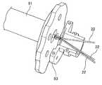
図5に示すように、操作部60は、固定台接続部62に長手方向に操作部本体63を摺動可能な直動手段64を介して取り付けられており、該直動手段64を長手方向に摺動させることで、鉗子30,屈曲部4およびシース・ワイヤ部5を長手方向に沿って押し引きすることができ、鉗子30の内視鏡チャンネル2a又は処置具挿通用チューブ2bからの突出量を調整することができる。なお、固定台接続部62は、保持手段71と操作部本体固定部72を備えており、操作部本体63は、保持手段71と操作部本体固定部72によって長手方向に保持されている。As shown in FIG. 5, the
図6に示すように、操作部60は、シース・ワイヤ部5に挿通されている複数の屈曲用ワイヤ22に接続されたグリップ61を操作部本体63に対してジョイスティックのように上下左右に回動させることで屈曲部4に挿通及び接続されたワイヤを長手方向に押し引きすることで屈曲部4の屈曲動作を行っている。また、グリップ61は、グリップ部67を備えており、該グリップ部67を長手方向に押引動作することもでき、この動作によって鉗子30及び電気メスに接続されたデバイス用ワイヤを押し引きすることで鉗子30の開閉動作及び電気メスの出没操作を行っている。As shown in FIG. 6, the
グリップ61は、屈曲用ワイヤ22が取り付けられる屈曲用ワイヤ牽引部66と、デバイス用ワイヤ23が取り付けられるグリップ部67とを備えている。屈曲用ワイヤ牽引部66は、複数の屈曲用ワイヤ22を取り付け可能且つグリップ61をジョイスティック様に操作可能なように球状に形成された屈曲用ワイヤ牽引部本体66aと、グリップ部67と略同心状に形成されると共に、屈曲用ワイヤ牽引部本体66aから軸心方向に延設すると共に径方向に突出して外側面が略球状に形成された形成された球状凸部81とを備えている。The
また、操作部本体63には、案内部65が収容されており、案内部65は、デバイス用ワイヤ23が貫通している。また、案内部65は、上述した球状凸部81に対応した球状凹部82が形成されており、球状凸部81と球状凹部82とが摺動自在に係合することで軸合わせ機構80を構成している。軸合わせ機構80は、操作部本体63に対して屈曲用ワイヤ牽引部66を上下左右に回動可能に案内すると共に、屈曲用ワイヤ牽引部66の回動に伴ってデバイス用ワイヤ23が屈曲した場合に、軸合わせ機構80の位置でデバイス用ワイヤ23とシース・ワイヤ部5の軸を合わせることで、デバイス用ワイヤ23の押し引き動作を円滑にする。Further, the operation unit
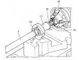
操作部本体63は、操作部本体63を固定台接続部62に対して回転自在に組み付ける回転手段90が取り付けられており、回転手段90には、固定台接続部62に形成された固定部保持部74に嵌合する固定部91が取り付けられている。固定部91は、シース・ワイヤ部5と連続して、屈曲用ワイヤ22,デバイス用ワイヤ23,内シース21及び外シース24といったシース・ワイヤ部5の構成部材を挿通している。The operation section
回転手段90は、図7から10に示すように、屈曲用ワイヤ22,デバイス用ワイヤ23及び内シース21が挿通されるワイヤホルダ92と、固定部91に対して回転自在に組み付けられる回転部93と、回転部93が組み付けられる回転制御部94とを備えている。As shown in FIGS. 7 to 10, the rotating
ワイヤホルダ92は、固定部91内に固定されて収納されている。また、ワイヤホルダ92は、複数の内シース21が絡まることが無いよう当該内シース21を1本ずつ通すことができる孔があり、その端部から内シース21が操作部本体63の内部に向けて突出しており、回転部93の内部で内シース21に挿通された複数の屈曲用ワイヤ22が広がって屈曲用ワイヤ牽引部66に架け渡されている。The
図9に示すように、回転部93は、一端が回転制御部94に摺動可能に組み付けられると共に、他端が操作部本体63に固定されるように組み付けられている。回転部93は操作部本体63と共に回転制御部94と一体に組み付けられた固定部91に対して軸回転可能に組み付けられている。また、回転制御部94には、回転部93の回転に対してストッパを形成し、回転部93が所定の角度を回転したとき当該ストッパによって回転が止まる機構を用いれば、必要以上に操作部本体63を回転させない機構とすることができる。これにより、固定部91に対して操作部本体63が回転可能な機構とすることができ、更に当該回転が所定以上回転しないような回転制御機構とすることができる。As shown in FIG. 9, the
このように、本実施形態に係る屈曲処置具は、固定部91と操作部本体63との間に回転手段90を備えているので、操作部本体63を固定台接続部62に対して回転させることができるので、屈曲処置具を内視鏡チャンネルに挿入した際に生じたねじれによって屈曲部4の屈曲方向と操作部60の入力方向にずれが生じた際に、操作部60の入力方向と屈曲部4の屈曲方向とを一致させることができ、直感的な操作を実現することができる。Thus, since the bending treatment tool according to the present embodiment includes the rotating
また、回転手段90は、回転部93を介して操作部本体63を取り付けているので、固定部91と操作部本体63との間に空間を設けることができ、該空間内で屈曲用ワイヤ22に所定の弛みを持たせることで屈曲用ワイヤ22同士の摩擦を低減して操作部本体63を円滑に回転させることができる。具体的には、回転手段90から案内部65端部までの位置、より具体的にはワイヤホルダ92の基端側端部から案内部65と屈曲用ワイヤ22とが接触している位置との間に適切な空間を設ければよい。例えば、ワイヤホルダ92の基端側端部から案内部65と屈曲用ワイヤ22とが接触している位置との間であれば、その空間距離は、好ましくは10mm以上、より好ましくは15mm以上、更に好ましくは20mm以上であり、好適は30mm以上である。In addition, since the rotation means 90 has the operation portion
さらに、ワイヤホルダ92から内シース21が操作部本体63内に突出するように延長しているので、屈曲用ワイヤ22同士が近接するワイヤホルダ92の端部において屈曲用ワイヤ22同士の摩擦を低減して操作部本体63を円滑に回転させることができる。また、内シース21は、操作部本体63内にまで延長していれば良いが、例えば、屈曲用ワイヤ22同士が絡まることを防止するために、屈曲用ワイヤ22が近接する箇所まで内シース21が延長していればよく、より好ましくは内シース21の先端を案内部65と屈曲用ワイヤ22が接触する位置まで延長すると好適である。具体的には、内シース21の先端を案内部65と接着や取付部材を介して固定すればなお好適である。Further, since the
次に、図11及び12を参照して固定台接続部62について説明を行う。固定台接続部62は、保持手段71と、保持手段71に対して近接・離間するように長手方向に沿って移動可能な操作部本体固定部72と、固定部91と係合して固定部91を固定する固定部保持部74とを備えている。操作部本体固定部72は、操作部本体63の末端に係合すると共に、長手方向に沿って近接するように移動することで操作部本体63を保持手段71と操作部本体固定部72とによって長手方向に保持することが可能となっている。Next, the fixed
このように構成されることで、屈曲処置具を固定台接続部62に容易に着脱自在に組み付けることができる。なお、操作部本体63の回転操作は、操作部本体固定部72を保持手段71から離間させて操作部本体63の保持を解除した状態で行うと好適である。With such a configuration, the bending treatment tool can be easily and detachably assembled to the fixed
なお、操作部本体固定部72は、回転ロック部73によって直動操作されており、図12に示すように、回転ロック部73は、操作部本体固定部72に形成されたラック75と歯合している。このように構成されることで、回転ロック部73を回転させると、回転ロック部73と噛み合ったラック75が長手方向に沿って移動することで操作部本体固定部72を保持手段71に対して近接・離間可能に構成している。The operation unit main
また、保持手段71及び操作部本体固定部72は、直動手段64を介して取付部78に組み付けられている。取付部78は、固定台70に組み付けることで手術時に屈曲処置具の位置を固定している。Further, the holding means 71 and the operation part main
直動手段64は、保持手段71と操作部本体固定部72とが組み付けられた直動板76と、直動板76を長手方向に沿って案内する案内装置77とから構成されており、直動板76が長手方向に沿って移動することで、保持手段71で保持した操作部本体63を長手方向に沿って移動させることができ、屈曲処置具を内視鏡チャンネル又は処置具挿通用チューブに対して屈曲処置具の挿入方向に移動させることができる。The linear motion means 64 includes a
このように、本実施形態に係る屈曲処置具は、屈曲部4及びシース・ワイヤ部5の外径を内視鏡チャンネルに挿通可能な3.8mm以下に極小化した場合であっても、操作部本体63の内部で屈曲部4の屈曲動作の際に屈曲部4の内部を挿通する屈曲用ワイヤ22やデバイス用ワイヤ23とヒンジ部材10の干渉によって屈曲動作を阻害することがなく、操作部60の操作による屈曲用ワイヤ22及びデバイス用ワイヤ23の押し引き動作を屈曲部4並びに鉗子30や電気メス36へ確実に伝達することができる。As described above, the bending treatment instrument according to the present embodiment operates even when the outer diameters of the
また、シース・ワイヤ部5の外径を極小化した場合であっても、シース・ワイヤ部5が例えば屈曲処置具を内視鏡チャンネル内に挿通させる際や、内視鏡の操作等により、内視鏡チャンネルの内部で捻じれが生じた場合であっても、操作部本体63を回転させることで操作軸を調整することができ、より直感的な操作が可能となる。Further, even when the outer diameter of the sheath /
[第2の実施形態]
以上説明した第1の実施形態に係る屈曲処置具では、操作部本体を固定台接続部を介して固定台に回転自在且つ、着脱自在に取り付けた場合について説明を行った。次に説明する第2の実施形態に係る屈曲処置具は、第1の実施形態とは異なる形態を有する実施例について説明を行うものである。なお、上述した第1の実施形態の場合と同一又は類似する部材については、同一符号を付して説明を省略する。[Second Embodiment]
In the bending treatment tool according to the first embodiment described above, the case where the operation unit main body is rotatably and detachably attached to the fixed base via the fixed base connecting part has been described. The bending treatment tool according to the second embodiment to be described next will be described with reference to an example having a form different from that of the first embodiment. Note that members that are the same as or similar to those in the first embodiment described above are given the same reference numerals, and descriptions thereof are omitted.
図13は、第2の実施形態に係る屈曲処置具の操作部の側面図であり、図14は、操作部の内部構造を説明するための分解図であり、図15は、回転手段の構造を説明するための分解図であり、図16は、捻じれ力逃がし機構の構造を説明するための分解図であり、図17は、軸固定部の斜視図であり、図18は、軸固定部の構造を説明するための分解図である。FIG. 13 is a side view of the operation part of the bending treatment instrument according to the second embodiment, FIG. 14 is an exploded view for explaining the internal structure of the operation part, and FIG. 15 is the structure of the rotating means. FIG. 16 is an exploded view for explaining the structure of the twisting force relief mechanism, FIG. 17 is a perspective view of the shaft fixing portion, and FIG. 18 is a shaft fixing. It is an exploded view for demonstrating the structure of a part.
図13及び14に示すように、本実施形態に係る屈曲処置具1´は、水平および鉛直方向に2自由度を有する屈曲部4の先端に取り付けられ後述するデバイス用ワイヤ23によって開閉自在に組付けられた図示しない鉗子又は電気メスと、屈曲部4の屈曲動作および鉗子の開閉動作又は電気メスの出没動作を行う操作部60´と、操作部60´の操作を伝達する複数の屈曲用ワイヤ22と該ワイヤを挿通するシースとを備えるシース・ワイヤ部5とを備えている。また、シース・ワイヤ部5には、軸固定手段100が取り付けられている。As shown in FIGS. 13 and 14, the bending treatment instrument 1 ′ according to the present embodiment is attached to the distal end of a bending
操作部60´は、固定台接続部62´に長手方向に操作部本体63´を摺動可能な直動手段64´を介して取り付けられており、該直動手段64´を長手方向に摺動させることで、屈曲部4およびシース・ワイヤ部5を長手方向に沿って押し引きすることができ、屈曲部の先端に取付けられた鉗子又は電気メスの内視鏡チャンネル2a又は処置具挿通用チューブ2bからの突出量を調整することができる。The
固定台接続部62´は、保持手段71´を備えている。保持手段71´は、長手方向と直交して延びる溝状の第1の係留部72a及び第2の係留部72bが形成されている。第1の係留部72aは、第2の係留部72bよりも高く形成されている。The fixed base connecting part 62 'includes holding means 71'. The holding means 71 ′ is formed with a groove-shaped first anchoring
また、操作部本体63´の先端側には、捻じれ力逃がし機構110が取り付けられ、該捻じれ力逃がし機構110を覆うようにカバー体79が取り付けられている。該カバー体79は、保持手段71´に形成された第1の係留部72a及び第2の係留部72bに対して第1の係留部72a及び第2の係留部72bの延設方向に沿って鉛直方向から圧入されることで固定台接続部62´と係留可能となっており、当該係留によって操作部本体63´を長手方向に保持している。なお、第1の係留部72aは、第2の係留部72bよりも長く形成されているので、操作部本体63´の着脱の際に、第2の係留部72bとの摩擦力が低減することで着脱が容易になるように形成されている。Further, a twisting
操作部60´は、シース・ワイヤ部5に挿通されている複数の屈曲用ワイヤ22に接続されたグリップ61´を操作部本体63´に対してジョイスティックのように上下左右に回動させることで屈曲部4に挿通及び接続されたワイヤを長手方向に押し引きすることで屈曲部4の屈曲動作を行っている。また、グリップ61´は、操作移動体69´を備えており、該操作移動体69´を長手方向に押引動作することもでき、この動作によって鉗子及び電気メスに接続されたデバイス用ワイヤ23を押し引きすることで鉗子の開閉動作及び電気メスの出没操作を行っている。The
グリップ61´は、屈曲用ワイヤ22が取り付けられる屈曲用ワイヤ牽引部66´と、デバイス用ワイヤ23が取り付けられるグリップ部67´とを備えている。また、操作部本体63´には、案内部65´が収容されており、案内部65´は、デバイス用ワイヤ23が貫通している。さらに、グリップ61´の先端には、円環状の指環部68´が形成されており、屈曲用ワイヤ牽引部66´の上下左右の回動操作及びグリップ部67´の往復動作が行いやすいように構成されている。The
図15に示すように、操作部本体63´は、操作部本体63´を固定台接続部62´に対して回転自在に組み付ける回転手段90´を介してカバー体79に組み付けられている。回転手段90´は、操作部本体63´の周方向に形成された回転溝63aにゴムなどの弾性材料からなる係止部材96と、カバー体79に該回転溝63aに対応して形成された回転突部95とを備えており、回転突部95が係止部材96に押圧されることで相互の摩擦力によって操作部本体63´とカバー体79との相対回転を係止している。なお、カバー体79と操作部本体63´とは、摩擦力によってのみ係止しているため、操作部本体63´を周方向に回転させる回転力を付与することで、比較的容易に操作部本体63´を回転させることができ、屈曲部4の屈曲方向とグリップ61´の操作方向とを一致させて操作性を向上させることができる。As shown in FIG. 15, the operation portion
本実施形態に係る屈曲処置具1´は、シース・ワイヤ部5に取り付けた軸固定手段100を内視鏡に設置した内視鏡ホルダに固定することができるので、屈曲処置具1´の挿入姿勢を固定することで、内視鏡チャンネル2a及び処置具挿通用チューブ2b内で屈曲部4やシース・ワイヤ部5が回転することを抑制し、グリップ部61´の操作方向と屈曲部4の屈曲方向が一致させる軸合わせ作業を行うことがないように構成されている。Since the bending treatment instrument 1 ′ according to the present embodiment can fix the shaft fixing means 100 attached to the sheath /
しかし、このような構成によると、操作部60´の取り扱い中にシース・ワイヤ部5等に余計な捻じり力が生じた場合、軸固定手段100に負荷が加わり、軸固定手段100が内視鏡ホルダから脱落するなどの問題が生じることが考えられる。これを防止するために、シース・ワイヤ部5に捻じり力が生じた場合に、これを分散する捻じり力逃がし機構110が操作部60´に取り付けられている。However, according to such a configuration, when an excessive twisting force is generated in the sheath /
図16に示すように、捻じれ力逃がし機構110は、シース・ワイヤ部5に挿通される屈曲用ワイヤ22及びデバイス用ワイヤ23が挿通される捻じれ力逃がし機構本体111と、該捻じれ力逃がし機構本体111に対して周方向に回転可能に組み付けられた回転体112とを備えている。回転体112は、シース・ワイヤ部5の端部に係留されており、図14に示すように、捻じれ力逃がし機構本体111と覆い部材113によって挟持されているので、回転体112は、デバイス用ワイヤ23及び屈曲用ワイヤ22の挿通方向には移動不能に保持されている。As shown in FIG. 16, the twisting
このように構成された捻じれ力逃がし機構110は、操作部60´の取り扱い中に操作部60´とシース・ワイヤ部5とに捻じれ力が生じた場合であっても、回転体112が捻じれ力に応じて回転することで該捻じれ力を分散して軸固定手段100へ負荷が加わることを防止している。The twisting
次に、図17及び18を参照して軸固定手段100の説明を行う。図17に示すように、軸固定手段100は、シース・ワイヤ部5が挿通される軸固定手段本体101と、軸固定手段本体101の先端側に取り付けられた先端係止部102とを備えている。軸固定手段本体101には、内視鏡ホルダに固定されるホルダ固定部101aが形成されており、該ホルダ固定部101aを内視鏡ホルダに固定することで、屈曲処置具1´の挿入姿勢を固定することができる。Next, the shaft fixing means 100 will be described with reference to FIGS. As shown in FIG. 17, the shaft fixing means 100 includes a shaft fixing means
図18に示すように、軸固定手段本体101には、長手方向に沿って溝が形成された軸固定部104が内蔵されており、該溝にシース・ワイヤ部5の外周に取り付けられた係合突起105が嵌合することでシース・ワイヤ部5の長手方向の摺動を可能とすると共に周方向の回転を防止している。なお、軸固定部104の長手方向の両端には、先端係止部102及び基端係止部103が取り付けられており、係合突起105がこれらの先端係止部102及び基端係止部103に当接することで長手方向の摺動を規制して係合突起105が軸固定部104の溝から脱落しないように構成されている。As shown in FIG. 18, the shaft fixing means
以上、本発明の好適な実施形態について説明したが、本発明の技術的範囲は上記実施形態の記載に限定されない。上記実施形態には、多様な変更又は改良を加えることが可能である。The preferred embodiments of the present invention have been described above, but the technical scope of the present invention is not limited to the description of the above embodiments. Various modifications or improvements can be added to the embodiment.
本実施形態に係る屈曲処置具は、鉗子用屈曲処置具1aとメス用屈曲処置具1bとを夫々内視鏡チャンネル2a及び処置具挿通用チューブ2bに挿通して同時に使用する場合について説明を行ったが、これらの鉗子用屈曲処置具1a及びメス用屈曲処置具1bはいずれか一方のみを用いても構わない。もしくは、鉗子用屈曲処置具1a、メス用屈曲処置具1b以外に、例えば、クリップ用屈曲処置具、圧排用屈曲処置具または持針器用屈曲処置具等を代わりに用いても構わない。また、本実施形態に係る屈曲処置具の操作部は、屈曲用ワイヤ牽引部66に球状凸部81を形成し、案内部65に球状凹部82を形成した軸合わせ機構80を備える例について説明を行ったが、この凹凸関係は逆に形成しても構わない。The bending treatment tool according to the present embodiment will be described with respect to a case where the forceps bending
その様な変更又は改良を加えた形態も本発明の技術的範囲に含まれ得ることが、特許請求の範囲の記載から明らかである。It is apparent from the description of the scope of claims that embodiments with such changes or improvements can also be included in the technical scope of the present invention.
1a 鉗子用屈曲処置具
1b メス用屈曲処置具
1´ 屈曲処置具
2 軟性内視鏡
2a 内視鏡チャンネル
2b 処置具挿通用チューブ
3 患者
3a 患部
4 屈曲部
5 シース・ワイヤ部
21 内シース
22 屈曲用ワイヤ
23 デバイス用ワイヤ
24 外シース
25 ライナーブレード
26 保護チューブ
30 鉗子
60,60´ 操作部
61,61´ グリップ
62,62´ 固定台接続部
63,63´ 操作部本体
64,64´ 直動手段
65,65´ 案内部
66,66´ 屈曲用ワイヤ牽引部
67,67´ グリップ部
68,68´ 指環部
70 固定台
71,71´ 保持手段
72 操作部本体固定部
72a 第1の係留部
72b 第2の係留部
73 回転ロック部
74 固定台保持部
75 ラック
76 直動板
77 案内装置
78 取付部
79 カバー体
80 軸合わせ機構
81 球状凸部
82 球状凹部
90,90´ 回転手段
91 固定部
92 ワイヤホルダ
93 回転部
94 回転制御部
95 回転突部
96 係止部材
100 軸固定手段
101 軸固定手段本体
101a ホルダ固定部
102 先端係止部
103 基端係止部
104 軸固定部
105 係合突起
110 捻じれ力逃がし機構
111 捻じれ力逃がし機構本体
112 回転体
113 覆い部材
DESCRIPTION OF SYMBOLS 1a Bending treatment tool for forceps 1b Bending treatment tool for female 1 'Bending treatment tool 2 Flexible endoscope 2a Endoscope channel 2b Treatment tool insertion tube 3 Patient 3a Affected part 4 Bending part 5 Sheath wire part 21 Inner sheath 22 Bending Wire 23 Device wire 24 Outer sheath 25 Liner blade 26 Protective tube 30 Forceps 60, 60 'Operation part 61, 61' Grip 62, 62 'Fixing base connection part 63, 63' Operation part main body 64, 64 'Linear motion means 65, 65 'guide portion 66, 66' bending wire pulling portion 67, 67 'grip portion 68, 68' finger ring portion 70 fixing base 71, 71 'holding means 72 operation portion main body fixing portion 72a first mooring portion 72b first 2 mooring parts 73 Rotation lock part 7 DESCRIPTION OF SYMBOLS 4 Fixed stand holding | maintenance part 75 Rack 76 Linear motion plate 77 Guide apparatus 78 Mounting part 79 Cover body 80 Axis alignment mechanism 81 Spherical convex part 82 Spherical concave part 90, 90 'Rotating means 91 Fixed part 92 Wire holder 93 Rotating part 94 Rotation control part 95 Rotating protrusion 96 Locking member 100 Shaft fixing means 101 Shaft fixing means main body 101a Holder fixing part 102 Tip locking part 103 Base end locking part 104 Shaft fixing part 105 Engaging protrusion 110 Torsional force relief mechanism 111 Torsional force relief Mechanism body 112 Rotating body 113 Cover member
Claims (10)
Translated fromJapanese操作部本体と、
前記デバイス用ワイヤが貫通する案内部と、
前記屈曲用ワイヤが接続されると共に、前記案内部に対して揺動自在に組み付けられた屈曲用ワイヤ牽引部と、
前記デバイス用ワイヤが接続されると共に、前記屈曲用ワイヤ牽引部の軸心方向に往復移動可能なグリップ部とを備えることを特徴とする操作部。A device wire that is provided with a treatment tool at the tip and that is connected to the treatment tool of a bending treatment tool that can be freely bent and operates the treatment tool, and a plurality of bending wires that cause the bending treatment tool to bend, respectively. An operation unit connected to perform the operation of the treatment tool and the bending operation of the bending treatment tool,
The operation unit body;
A guide portion through which the device wire penetrates;
A bending wire pulling portion connected to the bending wire and swingably assembled to the guide portion;
An operating portion comprising: a grip portion connected to the device wire and reciprocally movable in an axial direction of the bending wire pulling portion.
前記屈曲用ワイヤ牽引部と前記案内部とは、前記屈曲用ワイヤ牽引部又は前記案内部のいずれか一方に形成された球状凹部と、前記屈曲用ワイヤ牽引部又は前記案内部のいずれか他方に形成された球状凸部とを嵌め合わせた軸合わせ機構を備えることを特徴とする操作部。The operation unit according to claim 1,
The bending wire pulling portion and the guiding portion may be formed by either a spherical recess formed in either the bending wire pulling portion or the guiding portion, and the bending wire pulling portion or the guiding portion. An operation unit comprising an axis alignment mechanism in which a formed spherical convex portion is fitted.
前記操作部本体は、固定台接続部を介して固定台に着脱自在に取り付けることを特徴とする操作部。In the operation unit according to claim 1 or 2,
The operation unit body is detachably attached to a fixed base via a fixed base connection part.
前記操作部本体は、前記操作部本体を前記固定台接続部に対して回転自在に組み付ける回転手段が取り付けられ、
前記回転手段は、前記固定台接続部に固定される固定部を備えることを特徴とする操作部。The operation unit according to claim 3,
The operation unit main body is attached with a rotating means for assembling the operation unit main body rotatably with respect to the fixed base connection unit,
The operation unit, wherein the rotation unit includes a fixing unit fixed to the fixed base connection unit.
前記固定台接続部は、前記操作部本体を長手方向に保持する保持手段を備えることを特徴とする操作部。In the operation unit according to claim 3 or 4,
The operation part characterized in that the fixed base connection part includes holding means for holding the operation part main body in the longitudinal direction.
前記固定台接続部は、前記操作部本体を前記デバイス用ワイヤの延設方向に沿って案内する直動手段を備えることを特徴とする操作部。The operation unit according to any one of claims 3 to 5,
The operation part characterized in that the fixed base connection part includes a linear motion means for guiding the operation part main body along the extending direction of the device wire.
前記操作部本体は、前記デバイス用ワイヤ及び前記屈曲用ワイヤの周方向への捻じれを防止する捻じれ力逃がし機構を備えることを特徴とする操作部。In the operation unit according to any one of claims 1 to 6,
The operation unit main body includes a twisting force relief mechanism for preventing twisting of the device wire and the bending wire in the circumferential direction.
前記捻じれ力逃がし機構は、前記デバイス用ワイヤ及び前記屈曲用ワイヤを挿通する捻じれ力逃がし機構本体と、前記捻じれ力逃がし機構本体に対して前記デバイス用ワイヤ及び前記屈曲用ワイヤの挿通方向に移動不能且つ、周方向に回動可能に組み付けられた回転体とを備えることを特徴とする操作部。The operation unit according to claim 7,
The twisting force relief mechanism includes a twisting force relief mechanism main body for inserting the device wire and the bending wire, and an insertion direction of the device wire and the bending wire with respect to the twisting force relief mechanism main body. And a rotating body assembled to be rotatable in the circumferential direction.
前記固定台接続部は、前記操作部本体に取り付けられたカバー体を圧入で係留可能な保持手段を備えることを特徴とする操作部。The operation unit according to claim 3,
The operation unit according to claim 1, wherein the fixed base connection unit includes a holding unit capable of press-fitting a cover body attached to the operation unit main body.
前記保持手段は、長手方向と略直交して延びる溝状の第1の係留部と第2の係留部とを備えることを特徴とする操作部。The operation unit according to claim 9,
The operation unit is characterized in that the holding means includes a groove-shaped first mooring portion and a second mooring portion extending substantially orthogonal to the longitudinal direction.
Priority Applications (4)
| Application Number | Priority Date | Filing Date | Title |
|---|---|---|---|
| US15/564,597US10702352B2 (en) | 2015-04-15 | 2015-04-15 | Bending treatment instrument operating portion |
| PCT/JP2015/061563WO2016166828A1 (en) | 2015-04-15 | 2015-04-15 | Operating part for bendable treatment tool |
| JP2017512507AJP6482101B2 (en) | 2015-04-15 | 2015-04-15 | Operation unit for bending treatment tools |
| EP15889166.3AEP3284421B1 (en) | 2015-04-15 | 2015-04-15 | Operating part for bendable treatment tool |
Applications Claiming Priority (1)
| Application Number | Priority Date | Filing Date | Title |
|---|---|---|---|
| PCT/JP2015/061563WO2016166828A1 (en) | 2015-04-15 | 2015-04-15 | Operating part for bendable treatment tool |
Publications (1)
| Publication Number | Publication Date |
|---|---|
| WO2016166828A1true WO2016166828A1 (en) | 2016-10-20 |
Family
ID=57127052
Family Applications (1)
| Application Number | Title | Priority Date | Filing Date |
|---|---|---|---|
| PCT/JP2015/061563CeasedWO2016166828A1 (en) | 2015-04-15 | 2015-04-15 | Operating part for bendable treatment tool |
Country Status (4)
| Country | Link |
|---|---|
| US (1) | US10702352B2 (en) |
| EP (1) | EP3284421B1 (en) |
| JP (1) | JP6482101B2 (en) |
| WO (1) | WO2016166828A1 (en) |
Cited By (5)
| Publication number | Priority date | Publication date | Assignee | Title |
|---|---|---|---|---|
| WO2020084654A1 (en)* | 2018-10-22 | 2020-04-30 | オリンパス株式会社 | Medical manipulator |
| WO2021181494A1 (en)* | 2020-03-10 | 2021-09-16 | オリンパス株式会社 | Medical manipulator |
| EP3541316B1 (en)* | 2016-11-15 | 2022-05-04 | Medtronic Vascular Inc. | Stabilization and advancement system for direct aortic transcatheter aortic valve implantation |
| JP2023529459A (en)* | 2020-06-11 | 2023-07-10 | ボストン サイエンティフィック リミテッド | MEDICAL SYSTEMS, DEVICES AND RELATED METHODS |
| USD1010818S1 (en) | 2019-10-24 | 2024-01-09 | Olympus Corporation | Operating unit for surgical device |
Families Citing this family (2)
| Publication number | Priority date | Publication date | Assignee | Title |
|---|---|---|---|---|
| CN111789662A (en)* | 2020-08-12 | 2020-10-20 | 江苏唯德康医疗科技有限公司 | An ESD surgical traction device |
| CN116942259B (en)* | 2023-09-19 | 2023-12-01 | 苏州心锐医疗科技有限公司 | Surgical instrument for minimally invasive surgery |
Citations (5)
| Publication number | Priority date | Publication date | Assignee | Title |
|---|---|---|---|---|
| US5454827A (en)* | 1994-05-24 | 1995-10-03 | Aust; Gilbert M. | Surgical instrument |
| JP2007319661A (en)* | 2006-04-24 | 2007-12-13 | Ethicon Endo Surgery Inc | Medical instrument handle and medical instrument having handle |
| JP2009505688A (en)* | 2005-07-20 | 2009-02-12 | ケンブリッジ・エンドスコピック・ディヴァイセス,インコーポレーテッド | Surgical instrument guide device |
| US20110152609A1 (en)* | 2009-12-17 | 2011-06-23 | Ethicon Endo-Surgery, Inc. | User interface support devices for endoscopic surgical instruments |
| US20120118088A1 (en)* | 2010-11-17 | 2012-05-17 | Boston Scientific Scimed, Inc. | Bearing assembly for instrument |
Family Cites Families (4)
| Publication number | Priority date | Publication date | Assignee | Title |
|---|---|---|---|---|
| US9456877B2 (en) | 2006-12-01 | 2016-10-04 | Boston Scientific Scimed, Inc. | Direct drive instruments and methods of use |
| US9005238B2 (en)* | 2007-08-23 | 2015-04-14 | Covidien Lp | Endoscopic surgical devices |
| CA2722749A1 (en)* | 2008-04-29 | 2009-11-05 | Wilson-Cook Medical Inc. | Device platform for medical procedures |
| KR101326893B1 (en)* | 2012-04-27 | 2013-11-11 | 한양대학교 에리카산학협력단 | Manual surgical instrument with flexure |
- 2015
- 2015-04-15WOPCT/JP2015/061563patent/WO2016166828A1/ennot_activeCeased
- 2015-04-15USUS15/564,597patent/US10702352B2/ennot_activeExpired - Fee Related
- 2015-04-15EPEP15889166.3Apatent/EP3284421B1/enactiveActive
- 2015-04-15JPJP2017512507Apatent/JP6482101B2/ennot_activeExpired - Fee Related
Patent Citations (5)
| Publication number | Priority date | Publication date | Assignee | Title |
|---|---|---|---|---|
| US5454827A (en)* | 1994-05-24 | 1995-10-03 | Aust; Gilbert M. | Surgical instrument |
| JP2009505688A (en)* | 2005-07-20 | 2009-02-12 | ケンブリッジ・エンドスコピック・ディヴァイセス,インコーポレーテッド | Surgical instrument guide device |
| JP2007319661A (en)* | 2006-04-24 | 2007-12-13 | Ethicon Endo Surgery Inc | Medical instrument handle and medical instrument having handle |
| US20110152609A1 (en)* | 2009-12-17 | 2011-06-23 | Ethicon Endo-Surgery, Inc. | User interface support devices for endoscopic surgical instruments |
| US20120118088A1 (en)* | 2010-11-17 | 2012-05-17 | Boston Scientific Scimed, Inc. | Bearing assembly for instrument |
Cited By (5)
| Publication number | Priority date | Publication date | Assignee | Title |
|---|---|---|---|---|
| EP3541316B1 (en)* | 2016-11-15 | 2022-05-04 | Medtronic Vascular Inc. | Stabilization and advancement system for direct aortic transcatheter aortic valve implantation |
| WO2020084654A1 (en)* | 2018-10-22 | 2020-04-30 | オリンパス株式会社 | Medical manipulator |
| USD1010818S1 (en) | 2019-10-24 | 2024-01-09 | Olympus Corporation | Operating unit for surgical device |
| WO2021181494A1 (en)* | 2020-03-10 | 2021-09-16 | オリンパス株式会社 | Medical manipulator |
| JP2023529459A (en)* | 2020-06-11 | 2023-07-10 | ボストン サイエンティフィック リミテッド | MEDICAL SYSTEMS, DEVICES AND RELATED METHODS |
Also Published As
| Publication number | Publication date |
|---|---|
| JPWO2016166828A1 (en) | 2018-02-08 |
| EP3284421B1 (en) | 2019-11-20 |
| JP6482101B2 (en) | 2019-03-13 |
| EP3284421A1 (en) | 2018-02-21 |
| EP3284421A4 (en) | 2018-11-14 |
| US10702352B2 (en) | 2020-07-07 |
| US20180078323A1 (en) | 2018-03-22 |
Similar Documents
| Publication | Publication Date | Title |
|---|---|---|
| JP6482101B2 (en) | Operation unit for bending treatment tools | |
| JP7391956B2 (en) | Steerable equipment with tube elements | |
| EP2330965B1 (en) | Multi-linked endoscopic device with spherical distal assembly | |
| WO2011145533A1 (en) | Medical device | |
| EP2111806B1 (en) | Endoscope treatment instrument | |
| US8512317B2 (en) | Treatment apparatus | |
| JP6516172B2 (en) | Hinge member for bending treatment tool and bending treatment device incorporating the hinge member | |
| JP2008220972A (en) | Treatment instrument | |
| CN111970985A (en) | Low friction small medical tool with easily assembled components | |
| JP6284182B2 (en) | Operation unit for bending treatment tools | |
| WO2018070119A1 (en) | Bendable treatment instrument | |
| JP2015128535A (en) | Sheath for bending instruments | |
| WO2016166827A1 (en) | Sheath for bendable treatment tool and bendable treatment tool having said sheath incorporated therein | |
| JP6482051B2 (en) | Hinge member for bending treatment tool and bending treatment tool incorporating the hinge member | |
| US12213692B2 (en) | Treatment tool for endoscope | |
| JP7253063B2 (en) | endoscopic instrument | |
| US20220151650A1 (en) | Treatment tool for endoscope | |
| JP2024524192A (en) | Medical systems, devices, and related methods |
Legal Events
| Date | Code | Title | Description |
|---|---|---|---|
| 121 | Ep: the epo has been informed by wipo that ep was designated in this application | Ref document number:15889166 Country of ref document:EP Kind code of ref document:A1 | |
| ENP | Entry into the national phase | Ref document number:2017512507 Country of ref document:JP Kind code of ref document:A | |
| REEP | Request for entry into the european phase | Ref document number:2015889166 Country of ref document:EP | |
| WWE | Wipo information: entry into national phase | Ref document number:15564597 Country of ref document:US | |
| NENP | Non-entry into the national phase | Ref country code:DE |