WO2016158294A1 - Medical leak inspection device - Google Patents
Medical leak inspection deviceDownload PDFInfo
- Publication number
- WO2016158294A1 WO2016158294A1PCT/JP2016/057601JP2016057601WWO2016158294A1WO 2016158294 A1WO2016158294 A1WO 2016158294A1JP 2016057601 WJP2016057601 WJP 2016057601WWO 2016158294 A1WO2016158294 A1WO 2016158294A1
- Authority
- WO
- WIPO (PCT)
- Prior art keywords
- balloon member
- medical leak
- leak test
- tubular body
- test apparatus
- Prior art date
- Legal status (The legal status is an assumption and is not a legal conclusion. Google has not performed a legal analysis and makes no representation as to the accuracy of the status listed.)
- Ceased
Links
Images


Classifications
- A—HUMAN NECESSITIES
- A61—MEDICAL OR VETERINARY SCIENCE; HYGIENE
- A61B—DIAGNOSIS; SURGERY; IDENTIFICATION
- A61B1/00—Instruments for performing medical examinations of the interior of cavities or tubes of the body by visual or photographical inspection, e.g. endoscopes; Illuminating arrangements therefor
- A—HUMAN NECESSITIES
- A61—MEDICAL OR VETERINARY SCIENCE; HYGIENE
- A61B—DIAGNOSIS; SURGERY; IDENTIFICATION
- A61B10/00—Instruments for taking body samples for diagnostic purposes; Other methods or instruments for diagnosis, e.g. for vaccination diagnosis, sex determination or ovulation-period determination; Throat striking implements
Definitions
- the present inventionrelates to a medical leak inspection apparatus.
- This applicationclaims priority based on Japanese Patent Application No. 2015-069773 filed in Japan on March 30, 2015 and Japanese Patent Application No. 2016-001372 filed in Japan on January 6, 2016. And the contents thereof are incorporated herein.
- Patent Documents 1 and 2describe an arterial valve inspection device for inspecting whether or not the function of an arterial valve is normal.
- the arterial valve inspection devices described in these documentsare provided along the cylindrical portion, the visual window portion closing the front end portion or the rear end portion of the cylindrical portion, and the outer peripheral surface of the cylindrical portion.
- a balloon memberA balloon member.
- the arterial valve inspection deviceis fixed to the artery by inflating the balloon member with the arterial valve inspection device arranged on the downstream side of the arterial valve.
- liquidis injected into the space to fill the space.
- the function of the arterial valveis examined by monitoring the fluid pressure or amount of the space or by visually observing the arterial valve through the visual window.
- the present inventionhas been made in view of the above-described problems, and is a medical leak inspection apparatus used for inspection of arterial valves and the like, and can ensure a good visual field through a visual recognition window.
- a medical leak inspection apparatushaving a simple structure.
- the present inventionincludes the following aspects.
- a main bodyhaving a cylindrical part and a visual window part closing the cylindrical part,
- a balloon memberthat is provided along an outer peripheral surface of the tubular portion, and inflates toward the outside of the tubular portion by introducing a fluid between the tubular portion; and Injecting piping for injecting liquid into the space in front of the visual recognition window, An exhaust pipe for exhausting air from the space in front of the viewing window;
- a medical leak test apparatusconfigured such that an inflated portion formed by inflating the balloon member projects forward from a front end of the tubular portion.
- the front end of the balloon memberis a folded portion folded back,
- the medical leak test apparatusaccording to 1.
- the said exhaust holeis a medical leak test
- the medical leak inspection apparatusaccording to any one of (1) to (8), wherein the visual recognition window portion closes a rear end portion of the cylindrical portion.
- the medical leak test apparatuswherein a distance from the visual recognition window portion to the exhaust hole is equal to or less than an opening diameter of the exhaust hole.
- the liquid injection pipeis for injecting a myocardial protective solution.
- the medical leak inspection apparatusaccording to any one of (1) to (11), wherein at least one of a convex portion or a concave portion is formed on an outer surface of the balloon member.
- the convex portionis formed on an outer surface of the balloon member, and the convex portion includes a protrusion.
- the medical leak test apparatus(14) The medical leak test apparatus according to (13), wherein the protrusion is formed in an annular shape along a circumferential direction of the balloon member. (15) The medical leak test apparatus according to (14), wherein the protrusion is formed in a zigzag shape when viewed from a direction orthogonal to the axial direction of the cylindrical portion. (16) The medical leak test apparatus according to (14), wherein the protrusion is formed in a straight line when viewed from a direction orthogonal to the axial direction of the cylindrical portion. (17) The medical leak inspection apparatus according to (13), wherein the protrusions are formed in a lattice shape. (18) The medical leak test according to any one of (12) to (17), wherein the convex portion is formed on an outer surface of the balloon member, and the convex portion includes a dot-shaped protrusion. apparatus.
- the medical leak inspection apparatus of the present inventionit is possible to ensure a good visual field through the visual window.
- FIG. 1is an overall view of a medical leak inspection apparatus according to a first embodiment. It is a sectional side view which shows the front-end
- FIG. 3is a cross-sectional view taken along line BB in FIG. 2B. It is the front view seen from the arrow C direction of FIG. 2B.
- FIG. 14is a view for explaining a medical leak test apparatus according to an eighth embodiment, and is a cross-sectional view taken along line BB of FIG. 13A. It is a side view of the front-end
- the side closer to the operator side of the medical leak test apparatusis referred to as the base end (rear end), and the side farther from the operator is referred to as the front end (front end).
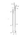
- FIG. 1is an overall view of a medical leak inspection apparatus 1 according to the first embodiment.
- FIG. 2Ais a side sectional view showing the distal end portion of the medical leak inspection apparatus 1 according to the first embodiment
- FIG. 2Bis a side view showing the distal end portion of the medical leak inspection apparatus 1 according to the first embodiment.
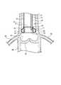
- FIG. 3is an enlarged sectional end view showing a portion A of FIG. 2A.
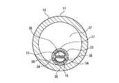
- 4Ais a cross-sectional view taken along line BB in FIG. 2B
- FIG. 4Bis a front view seen from the direction of arrow C in FIG. 2B. 4A and 4B, the balloon member 14, the balloon piping 22, the balloon connector 24, the liquid injection connector 25, and the exhaust connector 26 are not shown.
- FIG. 1is an overall view of a medical leak inspection apparatus 1 according to the first embodiment.
- FIG. 2Ais a side sectional view showing the distal end portion of the medical leak inspection apparatus 1 according to the first embodiment
- FIG. 2Bis a side view showing the dis
- FIG. 5is a side sectional view showing the distal end portion of the medical leak test apparatus 1 according to the first embodiment, and shows a state where the balloon member 14 is not inflated.
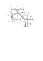
- FIG. 6is a cross-sectional view for explaining an example of use of the medical leak test apparatus 1 according to the first embodiment.
- the medical leak test apparatus 1includes a main body portion 13 having a tubular portion 11 and a visual recognition window portion 12 closing the tubular portion 11, a balloon member 14, and a liquid injection pipe 15. And an exhaust pipe 16.
- the balloon member 14is provided along the outer peripheral surface 17 of the cylindrical portion 11, and expands toward the outside of the cylindrical portion 11 by introducing a fluid between the balloon member 14 and the cylindrical portion 11.
- the liquid injection pipe 15performs liquid injection into the space 18 (FIG. 6) in front of the visual recognition window portion 12.
- the exhaust pipe 16exhausts air from the space 18 in front of the viewing window 12.
- the medical leak test apparatus 1is configured such that an inflated portion 19 formed by inflating the balloon member 14 projects forward from the front end of the tubular portion 11. That is, as shown in FIGS.
- the balloon member 14is inflated in a state in which the front portion of the inflating portion 19 projects forward from the front end of the tubular portion 11.
- interval between the front part (front part of the expansion part 19) of the balloon member 14 and the inner wall surfaces of body cavities, such as an arterycan be suppressed.
- the volume of the gap between the front part of the balloon member 14 (the front part of the inflating part 19) and the outer peripheral surface 17 of the cylindrical part 11can also be suppressed. Therefore, it is possible to suppress the observation visual field from being deteriorated due to the bubbles remaining in the gaps. Details will be described below.
- the medical leak test apparatus 1includes, for example, a balloon pipe 22 and a tubular body 23 in addition to a main body 13 provided with a balloon member 14.
- the distal end of the balloon pipe 22is fixed to the main body 13, and the proximal end side of the balloon pipe 22 extends to the rear of the main body 13.
- a balloon connector 24is provided at the proximal end of the balloon pipe 22.
- the tubular body 23accommodates therein the exhaust pipe 16 and the liquid injection pipe 15 and bundles and holds the exhaust pipe 16 and the liquid injection pipe 15.
- a distal end portion of the tubular body 23is fixed to the main body portion 13, and a proximal end side of the tubular body 23 extends rearward of the main body portion 13.
- the base end side portions of the liquid injection pipe 15 and the exhaust pipe 16are led out from the opening on the base end side of the tubular body 23.
- a liquid injection connector 25is provided at the base end of the liquid injection pipe 15, and an exhaust connector 26 is provided at the base end of the exhaust pipe 16.
- the distal end of the tubular body 23is open.
- the tubular body 23is more rigid than the exhaust pipe 16 and the liquid injection pipe 15. For this reason, in the longitudinal direction of the exhaust pipe 16 and the liquid injection pipe 15, the portion accommodated in the tubular body 23 is reinforced by the tubular body 23.
- the cylindrical portion 11is, for example, cylindrical.
- the visual recognition window portion 12closes the rear end portion of the tubular portion 11.
- the visual recognition window portion 12is plate-shaped, and the plate surface is orthogonal to the axial center of the tubular portion 11.
- the main-body part 13 containing the cylindrical part 11 and the window part 12 for visual recognitionthe whole is integrally formed, for example.
- the main body 13is made of, for example, a hard and transparent resin material such as polycarbonate.
- the length in the axial direction of the tubular portion 11(the length in the left-right direction in FIGS. 2A and 2B) is preferably shorter than the diameter of the tubular portion 11. In this way, the medical window inspection device 1 can be used with the visual window 12 closer to the observation target part (for example, an aortic valve), and thus the visibility of the observation target part is improved. Can be made.
- the balloon member 14has a cylindrical shape formed of a material having excellent elasticity such as silicon rubber.
- the balloon member 14is extrapolated around the outer peripheral surface 17 of the tubular portion 11, and the distal end portion (front end portion) and the proximal end portion (rear end portion) are respectively fixed to the tubular portion 11. .
- tip part and base end part of the balloon member 14 to the cylindrical part 11is not specifically limited, For example, it can be set as adhesive fixation.
- the front end portion of the balloon member 14(hereinafter also referred to as the front end portion) is a folded portion 27 folded back, and is folded back.
- the part 27is fixed to the outer peripheral surface 17 of the cylindrical part 11.
- the rear end portion (hereinafter, rear end portion 28) of the balloon member 14extends rearward from the rear end of the inflating portion 19 and is fixed to the outer peripheral surface 17 of the tubular portion 11. In other words, the front end portion of the balloon member 14 is folded, whereas the rear end portion 28 of the balloon member 14 extends rearward without being folded back.
- the front end position of the portion of the folded portion 27 that is fixed (adhered) to the outer peripheral surface 17 of the cylindrical portion 11is aligned with the front end position of the outer peripheral surface 17.
- the portion adjacent to the folded portion 27is more than the front end of the tubular portion 11 in a state before the balloon member 14 is inflated.
- a protruding portion 14aprotruding forward.
- the inflating portion 19has a shape that swells in an arc shape not only toward the outside of the tubular portion 11 but also toward the front. .
- the portion (maximum expansion portion 20) having the largest bulge in the expansion portion 19coincides with, for example, the center position 21 in the front-rear direction of the expansion portion 19.
- the center position 21is a position where both the distance from the front end and the distance from the rear end of the inflating portion 19 are L / 2.
- the position of the maximum expansion portion 20 in the front-rear directioncoincides with the center position 21.
- the maximum expansion portion 20may be slightly shifted in the front-rear direction with respect to the center position 21.
- the balloon pipe 22is a pipe for supplying a fluid to the gap between the balloon member 14 and the cylindrical portion 11 and discharging the fluid from the gap.
- the front end portion of the balloon pipe 22is interposed between the rear end portion 28 and the outer peripheral surface 17 of the tubular portion 11, and the inner space of the balloon member 14 (the space between the balloon member 14 and the outer peripheral surface 17 of the tubular portion 11 is In the gap).
- the fluid supplied to the gap between the balloon member 14 and the cylindrical portion 11may be a liquid or a gas.
- a fluidis passed through the balloon connector 24 and the balloon pipe 22 into the gap between the balloon member 14 and the tubular portion 11.
- the medical leak test apparatus 1includes a first balloon pipe for supplying fluid to the gap between the balloon member 14 and the tubular part 11, and a balloon member 14 and the tubular part 11 as balloon pipes. A second balloon pipe for discharging the fluid from the gap therebetween may be separately provided.
- the distal end portion of the tubular body 23protrudes forward of the visual recognition window portion 12 through a through hole 29 formed in the visual recognition window portion 12 so as to penetrate the visual recognition window portion 12 back and forth.
- the distal end of the tubular body 23is located in the internal space of the tubular portion 11 and does not protrude forward from the distal end of the tubular portion 11.
- the distal ends of the liquid injection pipe 15 and the exhaust pipe 16are accommodated together in a tubular body 23.
- the tip 30 of the injection pipe 15reaches the tip 32 of the tubular body 23.
- the tip 30 of the injection pipe 15 and the tip 32 of the tubular body 23are flat with no step. Yes.
- the distal end 31 of the exhaust pipe 16may reach the distal end 32 of the tubular body 23, or may not reach the distal end 32 of the tubular body 23 as illustrated (as illustrated, the distal end 31). May be located behind the tip 32).
- the exhaust pipe 16has a distal end 31 closed, and an exhaust suction port 34 is opened on the peripheral surface 33 of the distal end portion of the exhaust pipe 16.
- the exhaust pipe 16sucks the gas in the space 18 in front of the viewing window portion 12 through the exhaust suction port 34. That is, when the exhaust connector 26 is connected to an exhaust device (not shown), exhaust can be performed through the exhaust suction port 34, the exhaust pipe 16, and the exhaust connector 26.
- a liquid injection port 39 for injecting liquid into the space 18 in front of the visual recognition window 12is formed at the tip 30 of the liquid injection pipe 15.
- liquid injectioncan be performed via the liquid injection connector 25, the liquid injection pipe 15 and the liquid injection port 39.
- the space 18 (FIG. 6) in front of the visual recognition window portion 12includes an internal space of the tubular portion 11 and a space in front of the tubular portion 11 or the expanding portion 19.
- the medical leak inspection apparatus 1includes the tubular body 23 that holds the exhaust pipe 16 and the liquid injection pipe 15 in a bundle.
- An exhaust hole 38 that penetrates the tube wallis formed in the tube wall of the tubular body 23.
- the tubular body 23is configured such that the axial direction of the tubular body 23 is along the axial direction of the tubular portion 11, and the tubular body 23 is eccentric with respect to the tubular portion 11. In a state (for example, a state in which the tubular body 23 is inscribed in the tubular portion 11), the tubular body 11 is fixed to the tubular portion 11.
- the nearest contact point (for example, the inner contact 35) of the tubular body 23 to the tubular portion 11 and the tubular body 23is referred to as an opposing point 37.
- the exhaust hole 38opens closer to the closest point (for example, the inner contact point 35) than the facing point 37 on the outer peripheral surface of the tubular body 23.
- the exhaust hole 38is preferably arranged at a position corresponding to the exhaust suction port 34.
- the exhaust hole 38is located behind the liquid injection port 39 at the tip 30 of the liquid injection pipe 15.
- the liquid injection port 39is located on the distal side of the exhaust hole 38.
- the tubular body 23is formed with a pair of exhaust holes 38, and the exhaust pipe 16 is formed with a pair of exhaust suction ports 34.
- the exhaust hole 38 and the exhaust suction port 34are preferably arranged in the vicinity of the visual recognition window portion 12.
- the tubular body 23penetrates the visual recognition window portion 12 and projects forward from the visual recognition window portion 12.
- the exhaust hole 38is formed at a position ahead of the viewing window 12 on the tube wall of the tubular body 23.
- the distance from the visual recognition window 12 to the exhaust hole 38is, for example, equal to or smaller than the opening diameter of the exhaust hole 38. With such a configuration, the exhaust hole 38 can be disposed in the vicinity of the visual recognition window portion 12. Therefore, when the medical leak test apparatus 1 as shown in FIG. 6 is used, the exhaust from the space 18 can be suitably performed.
- the surface of the balloon member 14may be roughened.
- the frictional force of the balloon member 14 against the inner peripheral wall surface of a body cavity such as a blood vesselcan be increased (slip can be suppressed), and the medical leak test apparatus 1 Can be stably fixed to the body cavity.
- tacking (sticking) of the balloon member 14 to the outer peripheral surface 17 of the cylindrical portion 11can be suppressed.
- FIG. 5before the balloon member 14 is inflated, the inner surface of the balloon member 14 is in close contact with the outer peripheral surface 17 of the cylindrical portion 11. Can be easily peeled from the outer peripheral surface 17. Therefore, it becomes easy to inflate the balloon member 14 smoothly.
- the medical leak test apparatus 1checks whether or not the valve function of the aortic valve 52 (FIG. 6) is normal after aortic valvuloplasty and before suturing the aorta 54. Can be used.
- the cylindrical portion 11 at the distal end portion of the medical leak test apparatus 1is disposed inside the aorta 54 at a site downstream of the aortic valve 52 (hereinafter, downstream portion 51) and the aorta. It arrange
- FIG.Here, even in a state before the balloon member 14 is inflated, a part of the balloon member 14 protrudes forward from the front end of the tubular portion 11, so that the distal end portion of the medical leak test apparatus 1 is located downstream of the aorta 54.
- the balloon member 14is inflated to fix the main body 13 to the downstream side of the aortic valve 52.
- the space 18 between the main body 13 and the balloon member 14 of the medical leak test apparatus 1 and the aortic valve 52becomes a closed space.
- this spaceis connected to a pair of left and right coronary arteries 53.
- FIG. 6by lifting the proximal end side of the tubular body 23, the extending direction of the tubular body 23 is set to a substantially vertical direction, and the aortic valve 52 is disposed below the main body portion 13. Even during the following treatment, holding the tubular body 23 in a fixed position assists in fixing the main body 13 and the balloon member 14 of the medical leak test apparatus 1.
- a myocardial protective solutionis injected into the space 18 through the injection pipe 15. That is, the injection pipe 15 injects a myocardial protective liquid, for example.
- the exhaust from the space 18is performed in parallel with the injection of the myocardial protective solution into the space 18.
- the exhaust from the space 18is performed in parallel with the injection of the myocardial protective solution into the space 18.
- the exhaust from the space 18is performed in parallel with the injection of the myocardial protective solution into the space 18.
- the exhaust from the space 18is performed.
- the exhaust hole 38in the vicinity of the viewing window 12 such that the distance from the viewing window 12 to the exhaust hole 38 is equal to or smaller than the opening diameter of the exhaust hole 38, the exhaust from the space 18 is exhausted. This can be suitably performed, and the residual gas in the space 18 (particularly in the cylindrical portion 11) can be more suitably suppressed.
- a monitor of the pressure of the myocardial protective liquid in the space 18(hereinafter simply referred to as a pressure monitor) or the visual window 12
- the valve functionis determined by visual observation of the aortic valve 52 through the.
- the pressure monitorcan be performed using a pressure detection unit such as a fluid pressure detection transducer.
- the pressure detection unitcan be provided, for example, in a pipe connecting the exhaust pipe 16 and the exhaust connector 26 and the exhaust apparatus.
- the pressure detection unitcan monitor the pressure by shutting off the pipe and the exhaust device.
- the medical leak test apparatus 1is configured such that the inflatable portion 19 projects forward from the front end of the tubular portion 11.
- the gap 55 between the front surface of the inflating portion 19 and the inner peripheral wall surface of the downstream portion 51 of the aorta 54can be further reduced, and the remaining of bubbles in the gap 55 can be suppressed.
- the gap between the front surface of the expanding portion 19 and the outer peripheral surface 17 of the tubular portion 11can also be suppressed.
- the gapcan be substantially absent. Therefore, the phenomenon that bubbles that stay in the gap flow due to slight vibration during inspection and hinder the visual observation field is less likely to occur, so a good visual field through the visual window 12 is obtained. Can be secured.
- the configuration in which the inflating part 19 projects forward from the front end of the tubular part 11is a folded part 27 in which the front end part of the balloon member 14 is folded back, and the folded part 27 is the outer peripheral surface of the tubular part 11.
- the exhaust inlet 34is not located at the tip of the exhaust pipe 16 (lower end in the state of FIG. 6), but is located above the lower end of the exhaust pipe 16. Further, the exhaust hole 38 is disposed at a position corresponding to the exhaust suction port 34. Therefore, the myocardial protective liquid is passed through the exhaust suction port 34 or through the exhaust hole 38 and the exhaust suction port 34 with the gas still remaining in the space 18 (particularly in the cylindrical portion 11). Suction can be suppressed. Therefore, the residual gas in the space 18 (particularly in the cylindrical portion 11) can be more suitably suppressed.
- the gap between the outer peripheral surface of the tubular body 23 and the inner peripheral surface of the cylindrical portion 11is narrow in the vicinity of the inner contact 35. Therefore, in the vicinity of the inner contact 35, gas (bubbles) tends to stay and is difficult to be discharged (see FIG. 4A).
- the exhaust hole 38is opened closer to the inner contact 35 than the facing point 37 on the outer peripheral surface of the tubular body 23 in this embodiment. It can be easily discharged. Therefore, the phenomenon that the gas (bubbles) in the vicinity of the inner contact 35 flows due to slight vibration during inspection and hinders the visual field of visual observation is less likely to occur. A good field of view.
- FIG. 7is a cut end view when a part of the distal end portion of the medical leak test apparatus 1 according to the second embodiment is viewed from the side.
- the medical leak test apparatus 1 according to the present embodimentis different from the medical leak test apparatus 1 according to the first embodiment described above in that the protrusion 40 is formed on the balloon member 14.
- the medical leak inspection apparatus 1 according to the first embodimentis configured in the same manner.
- a protrusion 40is formed on the surface of the balloon member 14 between the folded portion 27 and a portion other than the folded portion 27 on the surface that is the inner space side of the inflatable portion 19.
- the protrusion 40is formed at the proximal end portion of the folded portion 27.
- the protrusion 40is, for example, an annular rib formed along the circumferential direction of the balloon member 14.
- the annular ribthat is, the protrusion 40 may be formed in an endless annular shape, may be formed in a C-annular shape, or may be a plurality of arc shapes intermittently arranged along the circumference. It may be an assembly of protrusions.
- the balloon member 14is folded along the protrusion 40 in a state where the inflating portion 19 is formed.
- the cross-sectional shape of the protrusion 40 cut along the axis of the cylindrical portion 11can be an oval shape such as a circle, an ellipse, or an oval.
- the cross-sectional shape of the protrusion 40may be a shape other than an oval shape such as a rectangular shape or a polygonal shape.
- the balloon member 14when the balloon member 14 is fixed to the main body 13 during the manufacture of the medical leak inspection apparatus 1, the balloon member 14 is used with the region where the protrusion 40 is formed in the balloon member 14 as a guide. Can be easily aligned with the main body 13. Therefore, the ease of manufacturing and the manufacturing stability of the medical leak inspection apparatus 1 can be improved.
- FIG. 8is a cut end view when a part of the distal end portion of the medical leak test apparatus 1 according to the third embodiment is viewed from the side.
- the medical leak test apparatus 1 according to the present embodimentis different from the medical leak test apparatus 1 according to the second embodiment described above in the arrangement of the protrusions 40 in the balloon member 14. It is comprised similarly to the medical leak test
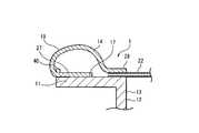
- FIG. 9is a cut end view when a part of the distal end portion of the medical leak test apparatus 1 according to the fourth embodiment is viewed from the side.
- the medical leak inspection apparatus 1 according to the present embodimentis different from the medical leak inspection apparatus 1 according to the first embodiment in the points described below, and in other points, the first implementation described above. It is comprised similarly to the medical leak test
- the point that the front side portion of the balloon member 14 is a folded portion 27 folded backis the same as in the first embodiment.
- the folded portion 27is fixed not to the outer peripheral surface 17 of the cylindrical portion 11 but to the inner peripheral surface 43.
- the portion disposed along the distal end surface 44 of the cylindrical portion 11may be fixed to the distal end surface 44 or simply in contact with the distal end surface 44.
- the portion of the balloon member 14 that is disposed along the distal end surface 44 of the tubular portion 11is fixed to the distal end surface 44.
- the front end surface 44is, for example, orthogonal to the axial direction of the cylindrical portion 11.
- the inner peripheral side portion of the cylindrical portion 11 and the outer peripheral side portion of the cylindrical portion 11may be cut to form a surface.
- the portion of the balloon member 14 that is disposed along the distal end surface 44is a portion that protrudes forward from the front end of the tubular portion 11 before the balloon member 14 is inflated.
- the same effects as those of the first embodimentcan be obtained, and the distal end of the tubular portion 11 is covered with the balloon member 14, so that the distal end of the tubular portion 11 with respect to the tissue of the subject can be obtained. Contact can be suppressed. Therefore, it can be made less invasive to a subject.
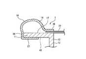
- FIG. 10is a cut end view when a part of the distal end portion of the medical leak test apparatus 1 according to the fifth embodiment is viewed from the side.
- the medical leak test apparatus 1 according to the present embodimentis different from the medical leak test apparatus 1 according to the fourth embodiment described above in the points described below, and in the other points, the fourth implementation described above. It is comprised similarly to the medical leak test
- the balloon member 14 of the medical leak test apparatus 1 according to the fourth embodimenthas the folded portion 27, whereas the balloon member 14 of the medical leak test apparatus 1 according to the present embodiment has the folded portion 27. I don't have it.
- the distal end portion 41 of the balloon member 14 according to the present embodimentis disposed along the distal end surface 44 of the tubular portion 11 and is fixed to the distal end surface 44.
- FIG. 11is a front view showing the distal end portion of the medical leak test apparatus 1 according to the sixth embodiment.
- the medical leak test apparatus 1 according to the present embodimentis different from the medical leak test apparatus 1 according to the first to fifth embodiments in the points described below. This is configured in the same manner as the medical leak inspection apparatus 1 according to the first to fifth embodiments.
- the tip of the tubular body 23is closed. That is, a wall-shaped blocking portion 42 is formed at the distal end of the tubular body 23.
- a through hole 45is formed at a position corresponding to the liquid injection port 39 at the tip of the liquid injection pipe 15 in the closing portion 42. Therefore, when a liquid such as a myocardial protective liquid is supplied via the liquid injection pipe 15, this liquid is led out from the distal end of the tubular body 23 via the liquid injection port 39 and the through hole 45.
- FIG. 12Ais a view for explaining the medical leak test apparatus 1 according to the seventh embodiment, and is a side sectional view of the distal end portion.
- FIG. 12Bis a view for explaining the medical leak test apparatus 1 according to the seventh embodiment, and is an enlarged view of a portion D in FIG. 12A.
- the medical leak test apparatus 1 according to the present embodimentis different from the medical leak test apparatus 1 according to the first to fifth embodiments in the points described below. This is configured in the same manner as the medical leak inspection apparatus 1 according to the first to fifth embodiments.
- the visual recognition window portion 12closes the front end portion of the tubular portion 11.
- the distal end 32 of the tubular body 23has reached the front surface of the visual recognition window portion 12 (which is also the front end of the tubular portion 11). More specifically, for example, there is a step between the distal end 32 and the front surface of the visual recognition window portion 12. There is no flat.
- the distal end 31 of the exhaust pipe 16is retracted to the proximal end side with respect to the distal end 32 of the tubular body 23, for example.
- the tip 31 of the exhaust pipe 16may be arranged flat with no step from the tip 32.
- a net-like exhaust suction port 34is opened at the tip 31 of the exhaust pipe 16. That is, the distal end 31 of the exhaust pipe 16 is closed by a plate-like closing portion 46 orthogonal to the axis of the exhaust pipe 16, and the closing portion 46 includes a plurality of penetrating through the closing portion 46.
- the hole 34ais formed, and the exhaust inlet 34 is constituted by these holes 34a.
- the distal end 31 of the exhaust pipe 16is located on the proximal side with respect to the distal end 32, and the exhaust suction port 34 is constituted by a plurality of minute holes 34a, so that the opening area of the hole 34a is reduced.
- the total(hereinafter referred to as total opening area) is smaller than the opening area of the space 47 outside the hole 34a. This causes pressure loss when the fluid moves from the space 47 to the hole 34a. Therefore, it is possible to prevent the liquid that is a heavy object from flowing into the hole 34a when exhausting through the exhaust pipe 16. Even if the number of holes opened at the tip 31 of the exhaust pipe 16 is one, the same effect can be obtained if the opening area (corresponding to the total opening area) is smaller than the opening area of the space 47.
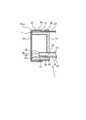
- FIG. 13Ais a view for explaining the medical leak test apparatus 1 according to the eighth embodiment, and is a side view of the distal end portion.
- FIG. 13Bis a view for explaining the medical leak test apparatus 1 according to the eighth embodiment, and is a cross-sectional view taken along the line BB of FIG. 13A.
- the medical leak test apparatus 1 according to the present embodimentis different from the medical leak test apparatus 1 according to the first to seventh embodiments in the points described below, and the other points are the above. This is configured in the same manner as the medical leak test apparatus 1 according to the first to seventh embodiments.
- At least one of a convex part (protrusion, dot-like protrusion, etc.) or a concave part (concave groove, dot-like concave part, etc.)is formed on the outer surface of the balloon member 14. Since the convex portion or the concave portion is formed on the outer surface of the balloon member 14, the convex portion or the concave portion functions as a non-slip, so that the grip property of the balloon member 14 with respect to the aorta or the artificial blood vessel is improved, and the balloon member 14. Can be well fixed to the aorta or artificial blood vessel.
- the balloon member 14can be satisfactorily fixed to the aorta or the artificial blood vessel.
- a convex portion 56is formed on the outer surface of the balloon member 14.
- the convex portion 56is in a state of projecting as compared with a portion other than the convex portion 56 on the outer surface of the balloon member 14 at least in a state where the balloon member 14 is inflated.
- the convex portion 56protrudes from a portion other than the convex portion 56 on the outer surface of the balloon member 14 even when the balloon member 14 is not inflated.
- the balloon member 14is made of silicon rubber or the like including the convex portion 56.
- the convex part 56contains a protrusion (rib).
- the convex part 56is formed in an annular shape along the circumferential direction of the balloon member 14 (circumferential direction perpendicular to the axis of the cylindrical part 11), for example.
- the convex portions 56 formed in an annular shape along the circumferential direction of the balloon member 14do not necessarily have to continuously circulate around the outer surface of the balloon member 14, and a plurality of convex portions 56 are intermittently formed in the circumferential direction. (Projections) may be arranged.
- the convex part 56is circling the outer surface of the balloon member 14, for example.
- the convex portion 56is formed in a zigzag shape when viewed from a direction orthogonal to the axial direction of the cylindrical portion 11. More specifically, a plurality of rows of convex portions 56 that are zigzag-shaped annular ribs are provided apart from each other.
- each convex part 56is located in a line in the axial direction of the cylindrical part 11, and each convex part 56 is extended mutually in parallel.
- the interval between the convex portions 56 that are zigzag ribsis uniform over the circumferential direction of the balloon member 14.
- the present inventionis not limited to the example in which the number of convex portions 56 that are annular ribs is a plurality of rows, and the number of convex portions 56 that are annular ribs may be one row.
- the convex portion 56functions as an anti-slip when the balloon member 14 is expanded in an aorta (blood vessel) or an artificial blood vessel. Therefore, the dropout of the balloon member 14 from the aorta or the artificial blood vessel and the displacement of the balloon member 14 with respect to the aorta or the artificial blood vessel can be suppressed, and the balloon member 14 can be more securely fixed to the aorta or the artificial blood vessel.
- the convex portion 56extends in the circumferential direction orthogonal to the axis of the cylindrical portion 11 and is formed in a zigzag shape, the stress in the axial direction of the cylindrical portion 11 with respect to the convex portion 56 Therefore, even when the balloon member 14 is inflated, the height (protrusion length) of the convex portion 56 can be sufficiently maintained, so that the balloon member 14 is displaced from the aorta or the artificial blood vessel in the circumferential direction and the axial direction. Can be suppressed.
- the plurality of rows of convex portions 56are provided apart from each other (not densely or adjacent to each other), the pressure required to inflate the balloon member 14 is reduced.
- the internal pressure of the balloon member 14 with respect to the aorta or the artificial blood vesselcan be reduced. Therefore, application of excessive force to the aorta or the artificial blood vessel can be suppressed, and the balloon member 14 can be more securely fixed to the aorta or the artificial blood vessel.
- the plurality of rows of protrusions 56are provided apart from each other, both the formation region and the non-formation region of the zigzag protrusions 56 are formed on the outer surface of the balloon member 14 on the entire circumference in the circumferential direction. Since it can be surely brought into contact with the inner wall of the aorta or the artificial blood vessel, the anti-slip effect can be more satisfactorily achieved.
- the interval between the convex portions 56 of the plurality of rowscan be, for example, 0.5 mm or more and 3 mm or less, preferably 1 mm or more and 2 mm or less.
- the cross-sectional shape of the convex portion 56is, for example, a trapezoid that becomes narrower toward the tip in the protruding direction.
- the height H of the convex portion 56is, for example, 0.2 mm or more and 0.5 mm or less, preferably 0.3 mm or more and 0.4 mm or less, when the balloon member 14 is contracted.
- the top width W1 and the bottom width W2 of the convex portion 56 (rib)are, for example, 0.15 mm or more and 0.6 mm or less, preferably 0.2 mm or more and 0.5 mm or less, when the balloon member 14 is contracted. It can be.
- the number of rows of the zigzag convex portions 56can be, for example, 2 to 8 rows. Moreover, it is preferable that the space
- the balloon member 14is manufactured by engraving a plurality of zigzag grooves arranged around the entire circumference of the core pin of the mold and spaced apart from each other in the axial direction. It can be produced by inverting the front and back of the balloon member 14. By doing so, the balloon member 14 having the zigzag convex portion 56 on the outer surface can be formed.
- the thickness of the balloon member 14can be, for example, 0.2 mm or more and 0.6 mm or less, preferably 0.3 mm or more and 0.5 mm or less, when the balloon member 14 is in a contracted state. By doing so, a sufficient pressure resistance for inflating the balloon can be obtained.
- the effective length of the balloonthat is, the length of the balloon member 14 in the axial direction of the tubular portion 11 when the balloon member 14 is inflated is, for example, 5 mm to 30 mm, preferably 6 mm to 20 mm. it can. By doing so, the balloon member 14 can be expanded to a sufficient size in order to place and fix the balloon member 14 in the blood vessel.
- the outer diameter of the balloon member 14 in the contracted statecan be, for example, 2 mm or more and 8 mm or less.
- FIG. 14is a side view of the distal end portion of the medical leak test apparatus 1 according to the ninth embodiment.
- the medical leak test apparatus 1 according to the present embodimentis different from the medical leak test apparatus 1 according to the eighth embodiment described above in the points described below, and in the other points, the eighth implementation described above. It is comprised similarly to the medical leak test
- the convex part 56which is a cyclic
- the interval between the protrusions 56 and the cross-sectional shape of the protrusions 56are the same as those in the eighth embodiment. That is, the cross-sectional view along the line BB in FIG. 14 is as shown in FIG. 13B.
- the convex portion 56when the balloon member 14 is inflated in an aorta (blood vessel) or an artificial blood vessel, the convex portion 56 functions as a slip stopper. Moreover, since the convex part 56 is linear, the very favorable anti-slip
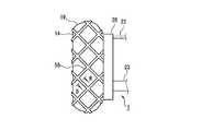
- FIG. 15is a side view of the distal end portion of the medical leak test apparatus 1 according to the tenth embodiment.
- the medical leak test apparatus 1 according to the present embodimentis different from the medical leak test apparatus 1 according to the eighth embodiment described above in the points described below, and in the other points, the eighth implementation described above. It is comprised similarly to the medical leak test
- the convex portions 56 that are ribs (ribs)are formed in a lattice shape.
- the interval between the protrusions 56 and the cross-sectional shape of the protrusions 56are the same as those in the eighth embodiment. That is, the cross-sectional view along the line BB in FIG. 15 is as shown in FIG. 13B.
- the convex portion 56when the balloon member 14 is inflated in an aorta (blood vessel) or an artificial blood vessel, the convex portion 56 functions as a slip stopper. Moreover, since the convex part 56 is a grid
- FIG. 16is a side view of the distal end portion of the medical leak test apparatus 1 according to the eleventh embodiment.
- the medical leak test apparatus 1 according to the present embodimentis different from the medical leak test apparatus 1 according to the eighth embodiment described above in the points described below, and in the other points, the eighth implementation described above. It is comprised similarly to the medical leak test
- the convex part 56is not a protrusion (rib) but a dot-like protrusion. That is, the convex part 56 is formed in the outer surface of the balloon member 14, and the convex part 56 contains a dot-shaped protrusion. More specifically, a plurality of convex portions 56 that are dot-like protrusions are formed on the outer surface of the balloon member 14. More specifically, a row of convex portions each including a plurality of convex portions 56 is formed in a plurality of rows on the outer surface of the balloon member 14. The arrangement direction of the protrusions 56 in each row is the circumferential direction of the balloon member 14. For example, the plurality of convex portions 56 are alternately arranged. A plurality of convex portions 56 are formed on the outer surface of the balloon member 14 so as to be evenly dispersed. Although the shape of the convex part 56 is not specifically limited, It is mentioned that it is elliptical or circular.
- the convex portion 56when the balloon member 14 is inflated in an aorta (blood vessel) or an artificial blood vessel, the convex portion 56 functions as a slip stopper. Further, since the convex portions 56 are alternately arranged, the anti-slip effect in various directions can be obtained uniformly, so that the balloon member 14 can be more stably fixed to the aorta or the artificial blood vessel. .
- a plurality of convex portions 56 that are dot-like projectionshas been described, but a single (one) convex portion 56 that is a dot-like projection is formed on the outer surface of the balloon member 14. May be.
- the fluidis introduced between the balloon member 14 and the cylindrical portion 11 through the balloon pipe 22 inserted between the balloon member 14 and the cylindrical portion 11.
- the balloon pipe 22directs the viewing window 12 from the rear to the front. And is introduced into the tubular portion 11 and the balloon pipe 22 penetrates the peripheral wall of the tubular portion 11 so that fluid can be introduced through the balloon pipe 22. It may be.
- the visual recognition window portion 12closes the front end portion of the tubular portion 11 as shown in FIG. 12A
- the balloon pipe 22is introduced into the tubular portion 11 from the rear of the tubular portion 11, Furthermore, since the balloon pipe 22 has a structure penetrating the peripheral wall of the cylindrical portion 11, fluid may be introduced through the balloon pipe 22.
- the target for which the medical leak test apparatus 1 is used for the leak testis not limited to the valve of the aorta (blood vessel) of a living body such as a subject. Furthermore, you may use the medical leak test
- the example in which the injection pipe 15 and the exhaust pipe 16 are reinforced by being accommodated in the tubular body 23has been described.
- the liquid injection pipe 15 and the exhaust pipe 16are arranged along the rod-shaped member (shaft) and fixed to the rod-shaped member, so that the liquid injection pipe 15 and the exhaust pipe 16 are reinforced. May be.
- the components of the medical leak test apparatus 1 of the present inventiondo not have to be independent of each other.
- a plurality of componentsare formed as one member, a component is formed of a plurality of members, one component is a part of another component, and one component is And a part of other components are allowed to overlap.
Landscapes
- Health & Medical Sciences (AREA)
- Life Sciences & Earth Sciences (AREA)
- Surgery (AREA)
- Medical Informatics (AREA)
- Molecular Biology (AREA)
- Veterinary Medicine (AREA)
- Pathology (AREA)
- Public Health (AREA)
- General Health & Medical Sciences (AREA)
- Engineering & Computer Science (AREA)
- Biomedical Technology (AREA)
- Heart & Thoracic Surgery (AREA)
- Animal Behavior & Ethology (AREA)
- Nuclear Medicine, Radiotherapy & Molecular Imaging (AREA)
- Physics & Mathematics (AREA)
- Biophysics (AREA)
- Radiology & Medical Imaging (AREA)
- Optics & Photonics (AREA)
- Ultra Sonic Daignosis Equipment (AREA)
Abstract
Description
Translated fromJapanese 本発明は、医療用リーク検査装置に関する。
本願は、2015年3月30日に、日本に出願された特願2015-069773号、及び、2016年1月6日に、日本に出願された特願2016-001372号に基づき優先権を主張し、その内容をここに援用する。The present invention relates to a medical leak inspection apparatus.
This application claims priority based on Japanese Patent Application No. 2015-069773 filed in Japan on March 30, 2015 and Japanese Patent Application No. 2016-001372 filed in Japan on January 6, 2016. And the contents thereof are incorporated herein.
特許文献1、2には、動脈弁の機能が正常かどうかを検査するための動脈弁検査装置が記載されている。これらの文献に記載された動脈弁検査装置は、筒状部と、筒状部の前端部又は後端部を閉塞している視認用窓部と、筒状部の外周面に沿って設けられたバルーン部材と、を備えている。
検査の際には、先ず、動脈弁検査装置を動脈弁の下流側に配置した状態でバルーン部材を膨張させることによって、動脈弁検査装置を動脈に対して固定する。次に、動脈弁検査装置と動脈弁との間の空間からの排気を行いながら、前記空間に液体を注入し、前記空間に液体を満たす。その後、前記空間の液圧または液量をモニターしたり、視認用窓部を介して動脈弁を目視観察したりすることにより、動脈弁の機能を検査する。In the examination, first, the arterial valve inspection device is fixed to the artery by inflating the balloon member with the arterial valve inspection device arranged on the downstream side of the arterial valve. Next, while exhausting from the space between the arterial valve inspection device and the arterial valve, liquid is injected into the space to fill the space. Thereafter, the function of the arterial valve is examined by monitoring the fluid pressure or amount of the space or by visually observing the arterial valve through the visual window.
ところで、動脈弁検査装置と動脈弁との間の空間に液体を注入する際に、前記空間内の気体を十分に排気できず、バルーン部材と動脈の内壁面との間隙などに気泡が残留していると、その後の検査時に生じる僅かな振動などによって気泡が流動し、この気泡が目視観察の視野を妨げてしまう可能性がある。By the way, when the liquid is injected into the space between the arterial valve inspection device and the arterial valve, the gas in the space cannot be exhausted sufficiently, and bubbles remain in the gap between the balloon member and the inner wall surface of the artery. If this is the case, bubbles may flow due to slight vibration generated during the subsequent inspection, and the bubbles may interfere with the visual field of visual observation.
本発明は上述のような課題に鑑みてなされたものであり、動脈弁などの検査に用いられる医療用リーク検査装置であって、視認用窓部を介した良好な視野を確保することが可能な構造の医療用リーク検査装置を提供する。The present invention has been made in view of the above-described problems, and is a medical leak inspection apparatus used for inspection of arterial valves and the like, and can ensure a good visual field through a visual recognition window. Provided is a medical leak inspection apparatus having a simple structure.
本発明は、以下の態様を包含する。
(1)筒状部と、前記筒状部を閉塞している視認用窓部と、を有する本体部と、
前記筒状部の外周面に沿って設けられ、前記筒状部との間に流体が導入されることにより、前記筒状部の外方に向けて膨張するバルーン部材と、
前記視認用窓部の前方の空間への注液を行うための注液用配管と、
前記視認用窓部の前方の前記空間からの排気を行うための排気用配管と、
を備え、
前記バルーン部材が膨張することにより形成される膨張部が前記筒状部の前端よりも前方に張り出すように構成されている医療用リーク検査装置。
(2)前記バルーン部材が膨らむ前の状態においても、前記バルーン部材の一部分が前記筒状部の前端よりも前方に突出している上記(1)に記載の医療用リーク検査装置。
(3)前記バルーン部材の前側の端部は、後方に折り返された折り返し部となっていて、
前記折り返し部が前記筒状部の前記外周面又は前記筒状部の内周面に固定されている上記(1)又は(2)に記載の医療用リーク検査装置。
(4)前記バルーン部材の後側の端部は、前記膨張部の後端から後方に向けて延びて、前記筒状部の前記外周面に固定されている上記(3)に記載の医療用リーク検査装置。
(5)前記バルーン部材における前記折り返し部と前記折り返し部以外の部分との境界部には、前記膨張部の内部空間側となる面に、突起が形成されている上記(3)又は(4)に記載の医療用リーク検査装置。
(6)前記突起は、前記バルーン部材の周方向に沿って形成されている環状リブである上記(5)に記載の医療用リーク検査装置。
(7)前記排気用配管の先端が閉塞しているとともに、前記排気用配管の先端部の周面には排気吸入口が開口しており、
前記排気用配管は、前記排気吸入口を介して、前記視認用窓部の前方の前記空間の気体を吸入する上記(1)から(6)のいずれか一項に記載の医療用リーク検査装置。
(8)前記排気用配管と前記注液用配管とを束ねて保持している管状体を有し、
前記管状体の管壁には、前記管壁を貫通する排気孔が形成され、
前記管状体は、前記管状体の軸心方向が前記筒状部の軸心方向に沿うとともに、前記管状体が前記筒状部に対して偏心した状態で、前記筒状部に固定されており、
前記管状体及び前記筒状部をそれらの前記軸心方向に対して直交する平面で切断した断面において、前記筒状部に対する前記管状体の最近接点と前記管状体の中心とを通る直線と前記管状体の外形線との交点のうち、前記最近接点でない方を対向点と称すると、
前記排気孔は、前記管状体の外周面において、前記対向点よりも前記最近接点の近くに開口している上記(1)から(7)のいずれか一項に記載の医療用リーク検査装置。
(9)前記視認用窓部は、前記筒状部の後端部を閉塞している上記(1)から(8)のいずれか一項に記載の医療用リーク検査装置。
(10)前記排気用配管と前記注液用配管とを束ねて保持している管状体を有し、
前記管状体は、前記視認用窓部を貫通して、前記視認用窓部よりも前方に突出しており、
前記管状体の管壁において前記視認用窓部よりも前方の位置には、前記管壁を貫通する排気孔が形成され、
前記視認用窓部から前記排気孔までの距離は、前記排気孔の開口径以下である上記(9)に記載の医療用リーク検査装置。
(11)前記注液用配管は、心筋保護液を注入するためのものである上記(1)から(10)のいずれか一項に記載の医療用リーク検査装置。
(12)前記バルーン部材の外表面に凸部又は凹部の少なくとも一方が形成されている上記(1)から(11)のいずれか一項に記載の医療用リーク検査装置。
(13)前記バルーン部材の外表面に前記凸部が形成されており、前記凸部は突条を含む上記(12)に記載の医療用リーク検査装置。
(14)前記突条は前記バルーン部材の周方向に沿って環状に形成されている上記(13)に記載の医療用リーク検査装置。
(15)前記突条は、前記筒状部の軸方向に対して直交する方向から視てジグザグ状に形成されている上記(14)に記載の医療用リーク検査装置。
(16)前記突条は、前記筒状部の軸方向に対して直交する方向から視て直線状に形成されている上記(14)に記載の医療用リーク検査装置。
(17)前記突条は、格子状に形成されている上記(13)に記載の医療用リーク検査装置。
(18)前記バルーン部材の外表面に前記凸部が形成されており、前記凸部は、ドット状の突起を含む上記(12)から(17)のいずれか一項に記載の医療用リーク検査装置。The present invention includes the following aspects.
(1) A main body having a cylindrical part and a visual window part closing the cylindrical part,
A balloon member that is provided along an outer peripheral surface of the tubular portion, and inflates toward the outside of the tubular portion by introducing a fluid between the tubular portion; and
Injecting piping for injecting liquid into the space in front of the visual recognition window,
An exhaust pipe for exhausting air from the space in front of the viewing window;
With
A medical leak test apparatus configured such that an inflated portion formed by inflating the balloon member projects forward from a front end of the tubular portion.
(2) The medical leak test apparatus according to (1), wherein a part of the balloon member protrudes further forward than the front end of the cylindrical portion even before the balloon member is inflated.
(3) The front end of the balloon member is a folded portion folded back,
The medical leak test apparatus according to (1) or (2), wherein the folded portion is fixed to the outer peripheral surface of the cylindrical portion or the inner peripheral surface of the cylindrical portion.
(4) The medical device according to (3), wherein a rear end portion of the balloon member extends rearward from a rear end of the inflatable portion and is fixed to the outer peripheral surface of the cylindrical portion. Leak inspection device.
(5) The above-mentioned (3) or (4), wherein a protrusion is formed on a surface on the inner space side of the inflating portion at a boundary portion between the folded portion and the portion other than the folded portion in the balloon member. The medical leak test apparatus according to 1.
(6) The medical leak test apparatus according to (5), wherein the protrusion is an annular rib formed along a circumferential direction of the balloon member.
(7) A tip of the exhaust pipe is closed, and an exhaust suction port is opened on a peripheral surface of the tip of the exhaust pipe,
The medical leak test apparatus according to any one of (1) to (6), wherein the exhaust pipe sucks the gas in the space in front of the viewing window through the exhaust suction port. .
(8) having a tubular body that holds the exhaust pipe and the liquid injection pipe in a bundle;
An exhaust hole penetrating the tube wall is formed in the tube wall of the tubular body,
The tubular body is fixed to the tubular portion in a state where the axial direction of the tubular body is along the axial direction of the tubular portion and the tubular body is eccentric with respect to the tubular portion. ,
In a cross section obtained by cutting the tubular body and the tubular portion along a plane orthogonal to the axial direction thereof, a straight line passing through the closest point of the tubular body to the tubular portion and the center of the tubular body, and Of the intersections with the outer shape of the tubular body, the one that is not the closest point is referred to as the opposite point.
The said exhaust hole is a medical leak test | inspection apparatus as described in any one of said (1) to (7) currently opened near the said closest point rather than the said opposing point in the outer peripheral surface of the said tubular body.
(9) The medical leak inspection apparatus according to any one of (1) to (8), wherein the visual recognition window portion closes a rear end portion of the cylindrical portion.
(10) having a tubular body that holds the exhaust pipe and the liquid injection pipe in a bundle;
The tubular body passes through the visual window part and protrudes forward from the visual window part,
In the tube wall of the tubular body, an exhaust hole penetrating the tube wall is formed at a position in front of the viewing window.
The medical leak test apparatus according to (9), wherein a distance from the visual recognition window portion to the exhaust hole is equal to or less than an opening diameter of the exhaust hole.
(11) The medical leak test apparatus according to any one of (1) to (10), wherein the liquid injection pipe is for injecting a myocardial protective solution.
(12) The medical leak inspection apparatus according to any one of (1) to (11), wherein at least one of a convex portion or a concave portion is formed on an outer surface of the balloon member.
(13) The medical leak test apparatus according to (12), wherein the convex portion is formed on an outer surface of the balloon member, and the convex portion includes a protrusion.
(14) The medical leak test apparatus according to (13), wherein the protrusion is formed in an annular shape along a circumferential direction of the balloon member.
(15) The medical leak test apparatus according to (14), wherein the protrusion is formed in a zigzag shape when viewed from a direction orthogonal to the axial direction of the cylindrical portion.
(16) The medical leak test apparatus according to (14), wherein the protrusion is formed in a straight line when viewed from a direction orthogonal to the axial direction of the cylindrical portion.
(17) The medical leak inspection apparatus according to (13), wherein the protrusions are formed in a lattice shape.
(18) The medical leak test according to any one of (12) to (17), wherein the convex portion is formed on an outer surface of the balloon member, and the convex portion includes a dot-shaped protrusion. apparatus.
本発明の医療用リーク検査装置によれば、視認用窓部を介した良好な視野を確保することが可能である。According to the medical leak inspection apparatus of the present invention, it is possible to ensure a good visual field through the visual window.
以下、本発明の実施形態を図面に基づいて説明する。尚、すべての図面において、同様の構成要素には同一の符号を付し、重複する説明は適宜に省略する。Hereinafter, embodiments of the present invention will be described with reference to the drawings. Note that in all the drawings, the same components are denoted by the same reference numerals, and redundant description will be appropriately omitted.
本明細書では、医療用リーク検査装置の操作者側に近い側を基端(後端)、前記操作者から遠い側を先端(前端)と呼ぶ。In this specification, the side closer to the operator side of the medical leak test apparatus is referred to as the base end (rear end), and the side farther from the operator is referred to as the front end (front end).
〔第1の実施形態〕
図1は第1の実施形態に係る医療用リーク検査装置1の全体図である。
図2Aは第1の実施形態に係る医療用リーク検査装置1の先端部を示す側断面図であり、図2Bは第1の実施形態に係る医療用リーク検査装置1の先端部を示す側面図である。
図3は図2AのA部を拡大して示す切断端面図である。
図4Aは図2BのB-B線に沿った矢視断面図であり、図4Bは図2Bの矢印C方向から見た正面図である。図4A及び図4Bにおいては、バルーン部材14、バルーン用配管22、バルーン用コネクタ24、注液用コネクタ25及び排気用コネクタ26の図示を省略している。
図5は第1の実施形態に係る医療用リーク検査装置1の先端部を示す側断面図であり、バルーン部材14が膨張していない状態を示す。
図6は第1の実施形態に係る医療用リーク検査装置1の使用例を説明するための断面図である。[First Embodiment]
FIG. 1 is an overall view of a medical
FIG. 2A is a side sectional view showing the distal end portion of the medical
FIG. 3 is an enlarged sectional end view showing a portion A of FIG. 2A.
4A is a cross-sectional view taken along line BB in FIG. 2B, and FIG. 4B is a front view seen from the direction of arrow C in FIG. 2B. 4A and 4B, the
FIG. 5 is a side sectional view showing the distal end portion of the medical
FIG. 6 is a cross-sectional view for explaining an example of use of the medical
本実施形態に係る医療用リーク検査装置1は、筒状部11と筒状部11を閉塞している視認用窓部12とを有する本体部13と、バルーン部材14と、注液用配管15と、排気用配管16と、を備えている。バルーン部材14は、筒状部11の外周面17に沿って設けられ、筒状部11との間に流体が導入されることにより、筒状部11の外方に向けて膨張する。注液用配管15は、視認用窓部12の前方の空間18(図6)への注液を行う。排気用配管16は、視認用窓部12の前方の空間18からの排気を行う。
バルーン部材14が膨張することにより形成される膨張部19が筒状部11の前端よりも前方に張り出すように、医療用リーク検査装置1は構成されている。すなわち、図2A、図2B及び図3に示すように、膨張部19の前部が筒状部11の前端よりも前方に突出した状態にバルーン部材14が膨張する。
これにより、バルーン部材14の前部(膨張部19の前部)と、動脈等の体腔の内壁面との間の間隙の体積を抑制することができる。また、バルーン部材14の前部(膨張部19の前部)と筒状部11の外周面17との間隙の体積も抑制することができる。よって、それらの間隙に滞留する気泡に起因して観察視野が不良となってしまうことを抑制することができる。
以下、詳細に説明する。The medical
The medical
Thereby, the volume of the gap | interval between the front part (front part of the expansion part 19) of the
Details will be described below.
図1に示すように、医療用リーク検査装置1は、例えば、バルーン部材14が設けられた本体部13の他、バルーン用配管22と、管状体23と、を備えている。As shown in FIG. 1, the medical
バルーン用配管22は、その先端部が本体部13に固定され、前記バルーン用配管22の基端側が本体部13の後方に延びている。バルーン用配管22の基端には、バルーン用コネクタ24が設けられている。The distal end of the
管状体23は、その内部に排気用配管16と注液用配管15とを収容し、これら排気用配管16と注液用配管15とを束ねて保持している。管状体23の先端部は本体部13に固定され、前記管状体23の基端側は本体部13の後方に延びている。
例えば、注液用配管15及び排気用配管16の各々の基端側部分は、管状体23の基端側の開口から導出されている。注液用配管15の基端には注液用コネクタ25が設けられ、排気用配管16の基端には排気用コネクタ26が設けられている。
本実施形態の場合、管状体23の先端は開口している。
管状体23は、例えば、排気用配管16及び注液用配管15よりも高剛性である。このため、排気用配管16及び注液用配管15の長手方向において、管状体23に収容されている部分は、管状体23によって補強されている。The
For example, the base end side portions of the
In the case of this embodiment, the distal end of the
For example, the
図2A、図2B、図4A及び図4Bに示すように、筒状部11は、例えば円筒状である。本実施形態の場合、視認用窓部12は、筒状部11の後端部を閉塞している。例えば、視認用窓部12は、板状のものであり、その板面が筒状部11の軸心に対して直交している。
筒状部11と視認用窓部12を含む本体部13は、例えば、その全体が一体形成されている。本体部13は、例えば、ポリカーボネートなどの硬質且つ透明な樹脂材料により構成されている。
筒状部11の軸方向における長さ(図2A及び図2Bにおける左右方向の長さ)は、筒状部11の直径よりも短いことが好ましい。このようにすることによって、視認用窓部12を観察対象部位(例えば大動脈弁など)に対してより接近させて医療用リーク検査装置1を用いることができるため、観察対象部位の視認性を向上させることができる。As shown in FIGS. 2A, 2B, 4A, and 4B, the
As for the main-
The length in the axial direction of the tubular portion 11 (the length in the left-right direction in FIGS. 2A and 2B) is preferably shorter than the diameter of the
バルーン部材14は、シリコンゴム等の伸縮性に優れた材料により形成された筒形状である。バルーン部材14は、筒状部11の外周面17の周囲に外挿され、且つ、その先端部(前端部)と基端部(後端部)とがそれぞれ筒状部11に固定されている。バルーン部材14の先端部及び基端部を筒状部11に固定する方法は、特に限定されないが、例えば、接着固定とすることができる。The
図2A及び図2Bに示すように、本実施形態の場合、バルーン部材14の前側の端部(以下、前端部という場合がある)は、後方に折り返された折り返し部27となっていて、折り返し部27が筒状部11の外周面17に固定されている。
一方、バルーン部材14の後側の端部(以下、後端部28)は、膨張部19の後端から後方に向けて延びて、筒状部11の外周面17に固定されている。換言すれば、バルーン部材14の前端部は折り返されているのに対し、バルーン部材14の後端部28は折り返されることなく、後方に延出している。As shown in FIG. 2A and FIG. 2B, in the case of this embodiment, the front end portion of the balloon member 14 (hereinafter also referred to as the front end portion) is a folded
On the other hand, the rear end portion (hereinafter, rear end portion 28) of the
また、折り返し部27において、筒状部11の外周面17に対して固定(接着)されている部位の前端位置は、外周面17の前端位置と揃っていることが好ましい。このようにすることにより、膨張部19が筒状部11の前端よりも前方に張り出す構造を容易に実現できる。バルーン部材14の前部(膨張部19の前部)と筒状部11の外周面17との間隙を抑制でき、例えば、実質的に間隙が存在しないようにすることが可能となる。Further, it is preferable that the front end position of the portion of the folded
バルーン部材14が膨らむ前の状態においても、バルーン部材14の一部分が筒状部11の前端よりも前方に突出していることが好ましい。
本実施形態の場合、図5に示すように、バルーン部材14における折り返し部27以外の部分において、折り返し部27に隣接する部分が、バルーン部材14が膨らむ前の状態において筒状部11の前端よりも前方に突出した突出部14aとなっている。
このような構造により、医療用リーク検査装置1を血管等の体腔内に挿入する際に、筒状部11と比べて柔らかいバルーン部材14の突出部14aが、筒状部11の先端よりも先に組織に接触するようにできるため、被験体(被験者等)にとって優しくなる(低侵襲となる)。つまり、バルーン部材14の突出部14aによって、被験体の組織を筒状部11の先端から保護することができる。Even in a state before the
In the case of the present embodiment, as shown in FIG. 5, in the portion other than the folded
With such a structure, when the medical
図2A、図2B及び図3に示すように、膨張部19は、例えば、筒状部11の外方に向けてだけでなく、前方に向けても弧状に膨らんだ形状となることが挙げられる。
図3に示すように、膨張部19において膨らみが最大の部分(最大膨張部20)は、例えば、前記膨張部19の前後方向における中心位置21と一致する。膨張部19の前後方向における長さをLとすると、膨張部19の前端からの距離と後端からの距離とがいずれもL/2となる位置が、中心位置21である。図3の例では、前後方向における最大膨張部20の位置は、中心位置21と一致している。ただし、最大膨張部20は、中心位置21に対して前後方向に若干ずれていても良い。As shown in FIGS. 2A, 2 </ b> B, and 3, for example, the inflating
As shown in FIG. 3, the portion (maximum expansion portion 20) having the largest bulge in the
バルーン用配管22は、バルーン部材14と筒状部11との間の間隙への流体の供給と、前記間隙からの流体の排出と、を行うための配管である。バルーン用配管22の先端部は、後端部28と筒状部11の外周面17との間を介して、バルーン部材14の内部空間(バルーン部材14と筒状部11の外周面17との間の間隙)に差し込まれている。
バルーン部材14と筒状部11との間の間隙に供給される流体は、液体であっても良いし、気体であっても良い。
バルーン用コネクタ24が図示しない給排液装置又は給排気装置と接続された状態で、バルーン用コネクタ24及びバルーン用配管22を介して、バルーン部材14と筒状部11との間の間隙に流体が供給されることにより、バルーン部材14が膨張し、膨張部19が形成される(図2A、図2B、図3)。
一方、膨張部19内の流体を、バルーン用配管22、バルーン用コネクタ24及び排液装置又は排気装置を介して排出することにより、膨張部19がしぼむ(図5)。排液装置又は排気装置としては、シリンジを用いることができる。
医療用リーク検査装置1は、バルーン用配管として、バルーン部材14と筒状部11との間の間隙への流体の供給用の第1バルーン用配管と、バルーン部材14と筒状部11との間の間隙からの流体の排出用の第2バルーン用配管と、を別個に備えていても良い。The
The fluid supplied to the gap between the
In a state where the
On the other hand, the fluid in the inflating
The medical
管状体23の先端部は、視認用窓部12を前後に貫通するように前記視認用窓部12に形成された貫通孔29を介して、視認用窓部12の前方に突出している。管状体23の先端は、筒状部11の内部空間に位置しており、筒状部11の先端より前方には突出していない。The distal end portion of the
図2Aに示すように、注液用配管15及び排気用配管16の先端部は、まとめて管状体23内に収容されている。
例えば、注液用配管15の先端30は管状体23の先端32に達しており、例えば、注液用配管15の先端30と管状体23の先端32とが段差が無くフラットな状態となっている。
一方、排気用配管16の先端31は、管状体23の先端32に達していても良いし、図示するように管状体23の先端32に達していなくても良い(図示のように、先端31は先端32よりも後方に位置していても良い)。As shown in FIG. 2A, the distal ends of the
For example, the
On the other hand, the
排気用配管16は、その先端31が閉塞しているとともに、前記排気用配管16の先端部の周面33には排気吸入口34が開口している。排気用配管16は、排気吸入口34を介して、視認用窓部12の前方の空間18の気体を吸入する。すなわち、排気用コネクタ26が図示しない排気装置に接続された状態では、排気吸入口34、排気用配管16及び排気用コネクタ26を介した排気が可能である。The
注液用配管15の先端30には、視認用窓部12の前方の空間18への注液を行うための注液口39が形成されている。注液用コネクタ25が図示しない注液装置に接続された状態では、注液用コネクタ25、注液用配管15及びその注液口39を介した注液が可能である。A
視認用窓部12の前方の空間18(図6)は、筒状部11の内部空間と、筒状部11又は膨張部19よりも前方の空間と、を含む。The space 18 (FIG. 6) in front of the visual
上記のように、医療用リーク検査装置1は、排気用配管16と注液用配管15とを束ねて保持している管状体23を有している。
管状体23の管壁には、前記管壁を貫通する排気孔38が形成されている。
図4A及び図4Bに示すように、管状体23は、前記管状体23の軸心方向が筒状部11の軸心方向に沿うとともに、前記管状体23が筒状部11に対して偏心した状態(例えば、管状体23が筒状部11に内接する状態)で、筒状部11に固定されている。
ここで、管状体23及び筒状部11をそれらの軸心方向に対して直交する平面で切断した断面において、筒状部11に対する管状体23の最近接点(例えば内接点35)と管状体23の中心36とを通る直線と管状体23の外形線との交点のうち、最近接点(例えば内接点35)でない方を対向点37と称することとする。
排気孔38は、管状体23の外周面において、対向点37よりも最近接点(例えば内接点35)の近くに開口している。As described above, the medical
An
As shown in FIGS. 4A and 4B, the
Here, in the cross section obtained by cutting the
The
図4Aに示すように、排気孔38は排気吸入口34と対応する位置に配置されていることが好ましい。この場合、排気孔38は、注液用配管15の先端30の注液口39よりも後方に位置する。換言すれば、注液口39は排気孔38よりも遠位側に位置する。これにより、注液口39からの液体の注入と排気孔38を介した排気とを好適に並行して行うことができる。しかも、後述するように注液口39よりも排気孔38が上方に位置する姿勢で医療用リーク検査装置1を用いることにより、空間18内における気体の残留を極力抑制することができる。
例えば、管状体23には一対の排気孔38が形成されており、排気用配管16には一対の排気吸入口34が形成されている。
また、図2A及び図2Bに示すように、排気孔38及び排気吸入口34は、視認用窓部12の近傍に配置されていることが好ましい。
ここで、管状体23は、視認用窓部12を貫通して、視認用窓部12よりも前方に突出している。排気孔38は、管状体23の管壁において視認用窓部12よりも前方の位置に形成されている。視認用窓部12から排気孔38までの距離は、例えば、排気孔38の開口径以下となっている。このような構成とすることにより、排気孔38を視認用窓部12の近傍に配置することができる。よって、図6に示すような医療用リーク検査装置1の使用時において、空間18からの排気を好適に行うことができる。As shown in FIG. 4A, the
For example, the
Further, as shown in FIGS. 2A and 2B, the
Here, the
バルーン部材14の表面は、粗面化されていても良い。
例えば、バルーン部材14の外表面を粗面化することにより、血管等の体腔の内周壁面に対するバルーン部材14の摩擦力を増大させることができ(滑りを抑制でき)、医療用リーク検査装置1を体腔に対して安定的に固定することが可能となる。
一方、バルーン部材14の内面を粗面化することにより、筒状部11の外周面17に対するバルーン部材14のタッキング(貼り付き)を抑制できる。図5に示すように、バルーン部材14が膨らむ前の状態では、バルーン部材14の内面は筒状部11の外周面17に密着した状態となっているが、このような状態から、バルーン部材14が外周面17から容易に剥離できるようになる。よって、バルーン部材14をスムーズに膨張させることが容易となる。The surface of the
For example, by roughening the outer surface of the
On the other hand, by roughening the inner surface of the
次に、本実施形態に係る医療用リーク検査装置1の使用例を説明する。
本実施形態に係る医療用リーク検査装置1は、例えば、大動脈弁形成術後、且つ、大動脈54の縫合前の段階で、大動脈弁52(図6)の弁機能が正常となったかどうかの検査に用いることができる。Next, a usage example of the medical
The medical
先ず、図6に示すように、医療用リーク検査装置1の先端部の筒状部11を、大動脈54において大動脈弁52よりも下流側の部位(以下、下流部51)の内部、且つ、大動脈弁52の近傍の位置に配置する。
ここで、バルーン部材14が膨らむ前の状態においても、バルーン部材14の一部分が筒状部11の前端よりも前方に突出しているので、医療用リーク検査装置1の先端部を大動脈54の下流部51に挿入する際に、筒状部11と比べて柔らかいバルーン部材14の突出部14aが、筒状部11の先端よりも先に組織に接触する。よって、被験体(被験者等)の負担を低減することができる。First, as shown in FIG. 6, the
Here, even in a state before the
次に、バルーン部材14を膨張させることによって、本体部13を大動脈弁52の下流側に固定する。これにより、医療用リーク検査装置1の本体部13及びバルーン部材14と、大動脈弁52と、の間の空間18は、閉空間となる。ただし、この空間は、左右一対の冠動脈53には繋がっている。
次に、図6に示すように、管状体23の基端側を持ち上げることにより、管状体23の延在方向を略鉛直方向とし、本体部13の下方に大動脈弁52を配置する。
以下の施術中においても、管状体23を一定位置に保持することによって、医療用リーク検査装置1の本体部13及びバルーン部材14の固定を補助する。Next, the
Next, as shown in FIG. 6, by lifting the proximal end side of the
Even during the following treatment, holding the
次に、注液用配管15を介して空間18に心筋保護液を注入する。すなわち、注液用配管15は、例えば、心筋保護液を注入する。ここで、空間18に心筋保護液を注入するのと並行して、空間18からの排気を行う。
ここで、視認用窓部12から排気孔38までの距離が排気孔38の開口径以下とするなど、排気孔38を視認用窓部12の近傍に配置することにより、空間18からの排気を好適に行うことができ、空間18内(特に筒状部11内)における気体の残留をより好適に抑制することができる。Next, a myocardial protective solution is injected into the
Here, by arranging the
空間18の心筋保護液が所定の圧力に達するとともに前記空間18からの排気が完了したら、空間18内の心筋保護液の圧力のモニター(以下、単に圧力モニターと称する)や、視認用窓部12を介した大動脈弁52の目視観察などを行うことによって、弁機能を判断する。圧力モニターは、液圧検知用のトランスデューサー等の圧力検知部を用いて行うことができる。圧力検知部は、例えば、排気用配管16及び排気用コネクタ26と排気装置とを接続する配管に設けることができる。例えば、空間18からの排気が完了した後で前記配管と排気装置との間を遮断することにより、圧力検知部による圧力モニターが可能となる。圧力モニターにより空間18内の圧力低下を確認することによって、弁機能に異常があることが分かる。また、目視観察では、大動脈弁52の閉まり具合などを観察する。When the myocardial protective liquid in the
ここで、本実施形態においては、膨張部19が筒状部11の前端よりも前方に張り出すように医療用リーク検査装置1が構成されている。これにより、膨張部19の前面と大動脈54の下流部51の内周壁面との間隙55をより小さくすることができ、前記間隙55における気泡の残留を抑制することができる。また、膨張部19の前面と筒状部11の外周面17との間隙も抑制でき、例えば、前記間隙が実質的に存在しないようにもできる。よって、それらの間隙に滞留する気泡が検査時の僅かな振動などにより流動して目視観察の視野を妨げてしまうといった現象が発生しにくくなるので、視認用窓部12を介した良好な視野を確保することができる。Here, in the present embodiment, the medical
膨張部19が筒状部11の前端よりも前方に張り出す構成は、バルーン部材14の前端部が後方に折り返された折り返し部27となっていて、折り返し部27が筒状部11の外周面17に固定されている構造を採用することにより、好適に実現することができる。The configuration in which the inflating
また、排気吸入口34は排気用配管16の先端(図6の状態で下端)には位置しておらず、排気用配管16の下端よりも上方に位置している。さらに、排気孔38は排気吸入口34と対応する位置に配置されている。よって、未だ空間18内(特に筒状部11内)に気体が残留している状態で、排気吸入口34を介して、あるいは、排気孔38及び排気吸入口34を介して、心筋保護液が吸引されてしまうことを抑制できる。よって、空間18内(特に筒状部11内)における気体の残留をより好適に抑制することができる。Further, the
ここで、管状体23の外周面と筒状部11の内周面との間隙は、内接点35の近傍において狭くなっている。したがって、内接点35の近傍においては、気体(気泡)が滞留しやすく排出されにくい(図4A参照)。このような事情に対し、本実施形態では、排気孔38は、管状体23の外周面において、対向点37よりも内接点35の近くに開口しているので、内接点35の近傍の気体を容易に排出することができる。よって、内接点35の近傍の気体(気泡)が検査時の僅かな振動などにより流動して目視観察の視野を妨げてしまうといった現象が発生しにくくなるので、視認用窓部12を介した良好な視野を確保することができる。Here, the gap between the outer peripheral surface of the
〔第2の実施形態〕
図7は第2の実施形態に係る医療用リーク検査装置1の先端部の一部分を側面視したときの切断端面図である。
本実施形態に係る医療用リーク検査装置1は、バルーン部材14に突起40が形成されている点で、上記の第1の実施形態に係る医療用リーク検査装置1と相違し、その他の点では、上記の第1の実施形態に係る医療用リーク検査装置1と同様に構成されている。[Second Embodiment]
FIG. 7 is a cut end view when a part of the distal end portion of the medical
The medical
本実施形態の場合、図7に示すように、バルーン部材14における折り返し部27と折り返し部27以外の部分との境界部には、膨張部19の内部空間側となる面に、突起40が形成されている。
本実施形態の場合、突起40は折り返し部27の基端部に形成されている。In the case of the present embodiment, as shown in FIG. 7, a
In the case of this embodiment, the
突起40は、例えば、バルーン部材14の周方向に沿って形成されている環状リブである。ここで、環状リブすなわち突起40は 無端の円環形状に形成されていても良いし、C環状の形状に形成されていても良いし、円周に沿って間欠的に配置された複数の弧状の突起の集合体であっても良い。The
図7に示すように、膨張部19が形成された状態では、突起40に沿ってバルーン部材14が折り返された状態となる。As shown in FIG. 7, the
筒状部11の軸心に沿って切断した突起40の断面形状は、例えば、円形、楕円形、長円形などのオーバルな形状とすることができる。突起40の断面形状は、矩形状、多角形状などの、オーバルな形状以外の形状であっても良い。The cross-sectional shape of the
本実施形態の場合、医療用リーク検査装置1の製造時において、バルーン部材14を本体部13に固定する際には、バルーン部材14において突起40が形成されている部位を目安として、バルーン部材14を本体部13に対して容易に位置合わせすることができる。よって、医療用リーク検査装置1の製造容易性ならびに製造安定性を向上させることができる。In the case of the present embodiment, when the
〔第3の実施形態〕
図8は第3の実施形態に係る医療用リーク検査装置1の先端部の一部分を側面視したときの切断端面図である。
本実施形態に係る医療用リーク検査装置1は、バルーン部材14における突起40の配置が、上記の第2の実施形態に係る医療用リーク検査装置1と相違し、その他の点では、上記の第2の実施形態に係る医療用リーク検査装置1と同様に構成されている。
すなわち、第2の実施形態では、突起40が折り返し部27の基端部に形成されているのに対し、本実施形態では、突起40がバルーン部材14における折り返し部以外の部分の先端部に形成されている。
この場合も、図8に示すように、膨張部19が形成された状態では、突起40に沿ってバルーン部材14が折り返された状態となる。
第3の実施形態によっても、第2の実施形態と同様の効果が得られる。[Third Embodiment]
FIG. 8 is a cut end view when a part of the distal end portion of the medical
The medical
That is, in the second embodiment, the
Also in this case, as shown in FIG. 8, the
According to the third embodiment, the same effect as the second embodiment can be obtained.
〔第4の実施形態〕
図9は第4の実施形態に係る医療用リーク検査装置1の先端部の一部分を側面視したときの切断端面図である。
本実施形態に係る医療用リーク検査装置1は、以下に説明する点で、上記の第1の実施形態に係る医療用リーク検査装置1と相違し、その他の点では、上記の第1の実施形態に係る医療用リーク検査装置1と同様に構成されている。[Fourth Embodiment]
FIG. 9 is a cut end view when a part of the distal end portion of the medical
The medical
本実施形態の場合、バルーン部材14の前側部が、後方に折り返された折り返し部27となっている点は、第1の実施形態と同様である。ただし、折り返し部27は、筒状部11の外周面17ではなく、内周面43に固定されている。
バルーン部材14において、筒状部11の先端面44に沿って配置されている部分は、前記先端面44に固定されていても良いし、単に先端面44に接触しているだけでも良い。
図9の例では、バルーン部材14において、筒状部11の先端面44に沿って配置されている部分は、先端面44に固定されている。In the case of the present embodiment, the point that the front side portion of the
In the
In the example of FIG. 9, the portion of the
先端面44は、例えば、筒状部11の軸心方向に対して直交している。先端面44において、筒状部11の内周側の部分、および、筒状部11の外周側の部分は、角を削り取って面を作っていても良い。The
本実施形態の場合、バルーン部材14において、先端面44に沿って配置されている部分が、バルーン部材14が膨らむ前の状態において筒状部11の前端よりも前方に突出している部分である。In the case of the present embodiment, the portion of the
本実施形態によれば、第1の実施形態と同様の効果が得られる他、筒状部11の先端がバルーン部材14により覆われているため、被験体の組織に対する筒状部11の先端の接触を抑制できる。よって、被験体に対してより低侵襲とすることができる。According to the present embodiment, the same effects as those of the first embodiment can be obtained, and the distal end of the
〔第5の実施形態〕
図10は第5の実施形態に係る医療用リーク検査装置1の先端部の一部分を側面視したときの切断端面図である。
本実施形態に係る医療用リーク検査装置1は、以下に説明する点で、上記の第4の実施形態に係る医療用リーク検査装置1と相違し、その他の点では、上記の第4の実施形態に係る医療用リーク検査装置1と同様に構成されている。[Fifth Embodiment]
FIG. 10 is a cut end view when a part of the distal end portion of the medical
The medical
第4の実施形態に係る医療用リーク検査装置1のバルーン部材14は折り返し部27を有しているのに対し、本実施形態に係る医療用リーク検査装置1のバルーン部材14は折り返し部27を有していない。
本実施形態に係るバルーン部材14の先端部41は、筒状部11の先端面44に沿って配置され、且つ、前記先端面44に固定されている。The
The
本実施形態によっても、第4の実施形態と同様の効果が得られる。Also in this embodiment, the same effect as that of the fourth embodiment can be obtained.
〔第6の実施形態〕
図11は第6の実施形態に係る医療用リーク検査装置1の先端部を示す正面図である。
本実施形態に係る医療用リーク検査装置1は、以下に説明する点で、上記の第1乃至第5の実施形態に係る医療用リーク検査装置1と相違し、その他の点では、上記の第1乃至第5の実施形態に係る医療用リーク検査装置1と同様に構成されている。[Sixth Embodiment]
FIG. 11 is a front view showing the distal end portion of the medical
The medical
本実施形態の場合、管状体23の先端が閉塞している。すなわち、管状体23の先端には壁状の閉塞部42が形成されている。閉塞部42において注液用配管15の先端の注液口39と対応する位置には、貫通孔45が形成されている。
したがって、注液用配管15を介して心筋保護液等の液体を供給する際には、この液体は、注液口39及び貫通孔45を介して管状体23の先端より導出される。In the case of this embodiment, the tip of the
Therefore, when a liquid such as a myocardial protective liquid is supplied via the
また、排気用配管16を介して排気を行った後に、管状体23の内部の間隙に気体(気泡等)が残留していたとしても、この気体が管状体23の先端から外部に漏洩してしまうことが抑制される。このため、検査時の僅かな振動などにより気体が管状体23の外部に漏洩し、目視観察の視野を妨げてしまうといった現象が発生しにくくなる。よって、視認用窓部12を介した良好な視野を確保することができる。Further, even if gas (such as bubbles) remains in the gap inside the
〔第7の実施形態〕
図12Aは第7の実施形態に係る医療用リーク検査装置1を説明するための図であり、先端部の側断面図である。図12Bは第7の実施形態に係る医療用リーク検査装置1を説明するための図であり、図12AのD部の拡大図である。
本実施形態に係る医療用リーク検査装置1は、以下に説明する点で、上記の第1乃至第5の実施形態に係る医療用リーク検査装置1と相違し、その他の点では、上記の第1乃至第5の実施形態に係る医療用リーク検査装置1と同様に構成されている。[Seventh Embodiment]
FIG. 12A is a view for explaining the medical
The medical
本実施形態の場合、視認用窓部12は、筒状部11の前端部を閉塞している。
管状体23の先端32が視認用窓部12の前面(筒状部11の前端でもある)に達しており、より具体的には、例えば、先端32と視認用窓部12の前面とが段差が無くフラットな状態になっている。In the case of this embodiment, the visual
The
図12Bに示すように、排気用配管16の先端31は、例えば、管状体23の先端32よりも基端側に後退している。ただし、排気用配管16の先端31は先端32と段差が無くフラットな状態に配置されていても良い。As shown in FIG. 12B, the
排気用配管16の先端31には、例えば、網目状の排気吸入口34が開口している。すなわち、排気用配管16の先端31は、排気用配管16の軸心に対して直交する板状の閉塞部46によって閉塞されているが、閉塞部46には、前記閉塞部46を貫通する複数の孔34aが形成され、これら孔34aによって排気吸入口34が構成されている。For example, a net-like
このように、排気用配管16の先端31が先端32よりも基端側に位置し、且つ、排気吸入口34が複数の微小な孔34aにより構成されていることによって、孔34aの開口面積の合計(以下、総開口面積)が、孔34aの外方の空間47の開口面積よりも小さくなる。これにより、空間47から孔34aへと流体が移動する際に圧損が生じるようになる。よって、排気用配管16を介した排気時において、気体に比べて重量物である液体が孔34aへと流入してしまうことを抑制することができる。排気用配管16の先端31に開口する孔の数が1つであっても、その開口面積(上記総開口面積に相当)が空間47の開口面積よりも小さければ、同様の効果が得られる。In this way, the
〔第8の実施形態〕
図13Aは第8の実施形態に係る医療用リーク検査装置1を説明するための図であり、先端部の側面図である。図13Bは第8の実施形態に係る医療用リーク検査装置1を説明するための図であり、図13AのB-B線に沿った断面図である。
本実施形態に係る医療用リーク検査装置1は、以下に説明する点で、上記の第1乃至第7の実施形態に係る医療用リーク検査装置1と相違し、その他の点では、上記の第1乃至第7の実施形態に係る医療用リーク検査装置1と同様に構成されている。[Eighth Embodiment]
FIG. 13A is a view for explaining the medical
The medical
本実施形態の場合、バルーン部材14の外表面に凸部(突条、ドット状の突起など)又は凹部(凹溝、ドット状の凹部など)の少なくとも一方が形成されている。バルーン部材14の外表面に凸部又は凹部が形成されていることにより、この凸部又は凹部が滑り止めとして機能するので、大動脈または人工血管に対するバルーン部材14のグリップ性が向上し、バルーン部材14を大動脈または人工血管に対して良好に固定することができる。
この凸部又は凹部の少なくとも一部分は、筒状部11(図2A、図2B、図5等参照)の先端面よりも前方に配置されていることが好ましく、これにより、筒状部11よりも先端側の位置においても、バルーン部材14を大動脈または人工血管に対して良好に固定することができる。In the case of this embodiment, at least one of a convex part (protrusion, dot-like protrusion, etc.) or a concave part (concave groove, dot-like concave part, etc.) is formed on the outer surface of the
It is preferable that at least a part of the convex portion or the concave portion is disposed in front of the distal end surface of the cylindrical portion 11 (see FIGS. 2A, 2B, 5, etc.). Even at the position on the distal end side, the
より詳細には、本実施形態の場合、図13A及びBに示すように、バルーン部材14の外表面に凸部56が形成されている。
この凸部56は、少なくとも、バルーン部材14が膨張した状態で、バルーン部材14の外表面における凸部56以外の部分に比して突起した状態となる。一例として、凸部56は、バルーン部材14が膨張していない状態においても、バルーン部材14の外表面における凸部56以外の部分から突起した状態となっている。
バルーン部材14は、凸部56も含めてシリコンゴム等により構成されている。
本実施形態の場合、凸部56は突条(リブ)を含む。凸部56は、例えば、バルーン部材14の周方向(筒状部11の軸線に対して直交する周方向)に沿って環状に形成されている。More specifically, in the case of the present embodiment, as shown in FIGS. 13A and 13B, a
The
The
In the case of this embodiment, the
バルーン部材14の周方向に沿って環状に形成された凸部56は、必ずしも、バルーン部材14の外表面を連続的に周回していなくても良く、周方向において間欠的に複数の凸部56(突条)が配置されていても良い。
本実施形態の場合、凸部56は、例えば、バルーン部材14の外表面を周回している。更に詳細には、凸部56は、筒状部11の軸方向に対して直交する方向から視てジグザグ状に形成されている。
より具体的には、ジグザグ状の環状のリブである凸部56が、互いに離間して複数列設けられている。一例として、各凸部56の折れ曲がり箇所は、筒状部11の軸方向において並んでおり、各凸部56は互いに並列に延在している。換言すれば、ジグザグ状のリブである凸部56どうしの間隔は、バルーン部材14の周方向に亘って均一になっている。
ただし、本発明は、環状のリブである凸部56の数が複数列である例に限らず、環状のリブである凸部56が1列であってもよい。The
In the case of this embodiment, the
More specifically, a plurality of rows of
However, the present invention is not limited to the example in which the number of
このような凸部56がバルーン部材14に形成されていることにより、バルーン部材14を大動脈(血管)または人工血管内で膨張させた際に、凸部56が滑り止めとして機能する。よって、大動脈または人工血管からのバルーン部材14の脱落や、大動脈または人工血管に対するバルーン部材14の位置ずれを抑制でき、バルーン部材14をより確実に大動脈または人工血管に対して固定することができる。Since such a
また、凸部56が筒状部11の軸線に対して直交する周方向に延在しているとともにジグザグ状に形成されているため、凸部56に対して筒状部11の軸方向における応力がかかりにくいため、バルーン部材14の膨張時においても凸部56の高さ(突出長)を十分に維持できるため、周方向及び軸方向において、バルーン部材14が大動脈または人工血管に対して位置ずれしてしまうことを抑制できる。
また、複数列の凸部56が互いに離間して設けられている(密集していたり、または隣り合って接していたりするのではない)ため、バルーン部材14を膨張させるために要する圧力を小さくすることができ、すなわち、大動脈又は人工血管に対するバルーン部材14の内圧を小さくすることができる。よって、大動脈又は人工血管に対して過度の力をかけることを抑制でき、より安全にバルーン部材14を大動脈又は人工血管に対して固定することができる。また、複数列の凸部56が互いに離間して設けられていることにより、周方向全周において、バルーン部材14の外表面においてジグザグ状の凸部56の形成領域と非形成領域との双方が大動脈又は人工血管の内壁に対して確実に接触するようにできるため、より良好に滑り止め効果を奏することができる。複数列の凸部56どうしの間隔は、例えば、0.5mm以上3mm以下、好ましくは1mm以上2mm以下とすることができる。Further, since the
In addition, since the plurality of rows of
図13Bに示すように、凸部56の断面形状は、例えば、突出方向先端に向けて幅狭になる台形状となっている。
凸部56の高さHは、バルーン部材14の収縮時の状態で、例えば0.2mm以上0.5mm以下、好ましくは0.3mm以上0.4mm以下とすることができる。また、凸部56(リブ)の頂部の幅W1および底部の幅W2は、バルーン部材14の収縮時の状態で、例えば0.15mm以上0.6mm以下、好ましくは0.2mm以上0.5mm以下とすることができる。As shown in FIG. 13B, the cross-sectional shape of the
The height H of the
ジグザグ状の凸部56の列数は、例えば、2列から8列とすることができる。また、ジグザグ状の凸部56どうしの間隔は、バルーン部材14の収縮時の状態でほぼ同一(等間隔)であることが好ましい。The number of rows of the zigzag
バルーン部材14の製造方法は、例えば、圧縮成形において、金型のコアピンの周方向全周に亘り、かつ軸線方向において互いに離間して配置されているジグザグ形状の溝を複数列彫り、圧縮成形後、バルーン部材14の表裏を反転させることによって作製することができる。こうすることにより、ジグザグ形状の凸部56を外表面に有するバルーン部材14を成形することができる。For example, in the compression molding, the
バルーン部材14の肉厚は、バルーン部材14が収縮時の状態で、例えば0.2mm以上0.6mm以下、好ましくは0.3mm以上0.5mm以下とすることができる。こうすることにより、バルーンを膨張させるための十分な耐圧を得ることができる。また、バルーンの有効長、すなわちバルーン部材14が膨張した際の、筒状部11の軸方向におけるバルーン部材14の長さは、例えば、5mm以上30mm以下、好ましくは6mm以上20mm以下とすることができる。こうすることにより、バルーン部材14を血管内に留置固定するために、バルーン部材14を十分な大きさに膨張させることができる。バルーン部材14の収縮時の状態の外径は、例えば、2mm以上8mm以下とすることができる。The thickness of the
〔第9の実施形態〕
図14は第9の実施形態に係る医療用リーク検査装置1の先端部の側面図である。
本実施形態に係る医療用リーク検査装置1は、以下に説明する点で、上記の第8の実施形態に係る医療用リーク検査装置1と相違し、その他の点では、上記の第8の実施形態に係る医療用リーク検査装置1と同様に構成されている。[Ninth Embodiment]
FIG. 14 is a side view of the distal end portion of the medical
The medical
本実施形態の場合、環状の突条(リブ)である凸部56は、ジグザグ状ではなく、筒状部11の軸方向に対して直交する方向から視て直線状に形成されている。より詳細には、凸部56は、筒状部11の軸方向に対して直交する方向に延在している。凸部56どうしの間隔及び凸部56の断面形状は第8の実施形態と同様である。すなわち、図14のB-B線に沿った断面図は、図13Bのようになる。In the case of this embodiment, the
本実施形態によっても、バルーン部材14を大動脈(血管)または人工血管内で膨張させた際に、凸部56が滑り止めとして機能する。また、凸部56が直線状であるため、筒状部11の軸方向において極めて良好な滑り止め効果を得ることができる。よって、筒状部11の軸方向においてバルーン部材14が大動脈または人工血管に対して位置ずれしてしまうことを好適に抑制することが可能である。Also in this embodiment, when the
〔第10の実施形態〕
図15は第10の実施形態に係る医療用リーク検査装置1の先端部の側面図である。
本実施形態に係る医療用リーク検査装置1は、以下に説明する点で、上記の第8の実施形態に係る医療用リーク検査装置1と相違し、その他の点では、上記の第8の実施形態に係る医療用リーク検査装置1と同様に構成されている。[Tenth embodiment]
FIG. 15 is a side view of the distal end portion of the medical
The medical
本実施形態の場合、突条(リブ)である凸部56が格子状に形成されている。凸部56どうしの間隔及び凸部56の断面形状は第8の実施形態と同様である。すなわち、図15のB-B線に沿った断面図は、図13Bのようになる。In the case of the present embodiment, the
本実施形態によっても、バルーン部材14を大動脈(血管)または人工血管内で膨張させた際に、凸部56が滑り止めとして機能する。また、凸部56が格子状であるため、様々な方向における滑り止め効果が得られるため、バルーン部材14を大動脈または人工血管に対してより安定的に固定することができる。Also in this embodiment, when the
〔第11の実施形態〕
図16は第11の実施形態に係る医療用リーク検査装置1の先端部の側面図である。
本実施形態に係る医療用リーク検査装置1は、以下に説明する点で、上記の第8の実施形態に係る医療用リーク検査装置1と相違し、その他の点では、上記の第8の実施形態に係る医療用リーク検査装置1と同様に構成されている。[Eleventh embodiment]
FIG. 16 is a side view of the distal end portion of the medical
The medical
本実施形態の場合、凸部56は突条(リブ)ではなく、ドット状の突起である。すなわち、バルーン部材14の外表面に凸部56が形成されており、凸部56は、ドット状の突起を含む。より詳細には、ドット状の突起である複数の凸部56がバルーン部材14の外表面に形成されている。
更に詳細には、各々複数の凸部56を含む凸部の列が、バルーン部材14の外表面に複数列に形成されている。各列における凸部56の並び方向は、バルーン部材14の周方向である。例えば、複数の凸部56は、それぞれ互い違いに配置されている。バルーン部材14の外表面に、複数の凸部56が均等に分散した配置で形成されている。凸部56の形状は特に限定されないが、楕円形又は円形などであることが挙げられる。In the case of this embodiment, the
More specifically, a row of convex portions each including a plurality of
本実施形態によっても、バルーン部材14を大動脈(血管)または人工血管内で膨張させた際に、凸部56が滑り止めとして機能する。また、凸部56がそれぞれ互い違いに配置されていることにより、様々な方向における滑り止め効果が均一に得られるため、バルーン部材14を大動脈または人工血管に対してより安定的に固定することができる。
ここでは、ドット状の突起である凸部56が複数形成されている例を説明したが、ドット状の突起である単数の(1個の)凸部56がバルーン部材14の外表面に形成されていても良い。Also according to this embodiment, when the
Here, an example in which a plurality of
本発明は上述の実施形態に限定されるものではなく、本発明の目的が達成される限りにおける種々の変形、改良等の態様も含む。各実施形態において説明された事項は適宜、他の実施形態に適用することが可能である。The present invention is not limited to the above-described embodiment, and includes various modifications and improvements as long as the object of the present invention is achieved. The matters described in each embodiment can be applied to other embodiments as appropriate.
また、上記の各実施形態では、バルーン部材14と筒状部11との間への流体の導入は、バルーン部材14と筒状部11との間に差し込まれたバルーン用配管22を介して行う例を説明したが、本発明は、この例に限定されない。
例えば、図2A、図2B等のように筒状部11の後端部を視認用窓部12が閉塞している場合には、バルーン用配管22が視認用窓部12を後方から前方に向けて貫通して筒状部11内に導入され、さらに前記バルーン用配管22が筒状部11の周壁を貫通した構造となっていることにより、バルーン用配管22を介した流体の導入が可能となっていても良い。
また、図12Aのように筒状部11の前端部を視認用窓部12が閉塞している場合には、バルーン用配管22が筒状部11の後方から筒状部11内に導入され、さらに前記バルーン用配管22が筒状部11の周壁を貫通した構造となっていることにより、バルーン用配管22を介した流体の導入が可能となっていても良い。In each of the above embodiments, the fluid is introduced between the
For example, when the
Further, when the visual
医療用リーク検査装置1をリーク検査に用いる対象は、被験者などの生体の大動脈(血管)の弁に限らない。さらには、腸閉塞や血栓(梗塞)の判定などに医療用リーク検査装置1を用いても良い。The target for which the medical
上記においては、注液用配管15及び排気用配管16が管状体23に収容されることにより補強されている例を説明した。ただし、注液用配管15及び排気用配管16が棒状部材(シャフト)に沿って配置されるとともに前記棒状部材に対して固定されていることにより、注液用配管15及び排気用配管16が補強されていても良い。この場合、棒状部材は、その長手方向に沿って延在する補強用のワイヤが内部に挿通されていることが好ましい。In the above description, the example in which the
本発明の医療用リーク検査装置1の構成要素は、個々に独立した存在である必要はない。複数の構成要素が一個の部材として形成されていること、一つの構成要素が複数の部材で形成されていること、ある構成要素が他の構成要素の一部であること、ある構成要素の一部と他の構成要素の一部とが重複していること、等を許容する。The components of the medical
視認用窓部を介した良好な視野を確保することが可能な構造の医療用リーク検査装置を提供することができる。It is possible to provide a medical leak inspection apparatus having a structure capable of ensuring a good visual field through the visual recognition window.
1 医療用リーク検査装置
11 筒状部
12 視認用窓部
13 本体部
14 バルーン部材
14a 突出部
15 注液用配管
16 排気用配管
17 外周面
18 空間
19 膨張部
20 最大膨張部
21 中心位置
22 バルーン用配管
23 管状体
24 バルーン用コネクタ
25 注液用コネクタ
26 排気用コネクタ
27 折り返し部
28 後端部
29 貫通孔
30 先端
31 先端
32 先端
33 周面
34 排気吸入口
34a 孔
35 内接点(最近接点)
36 中心
37 対向点
38 排気孔
39 注液口
40 突起
41 先端部
42 閉塞部
43 内周面
44 先端面
45 貫通孔
46 閉塞部
47 空間
51 下流部
52 大動脈弁
53 冠動脈
54 大動脈
55 間隙
56 凸部DESCRIPTION OF
36
Claims (18)
Translated fromJapanese前記筒状部の外周面に沿って設けられ、前記筒状部との間に流体が導入されることにより、前記筒状部の外方に向けて膨張するバルーン部材と、
前記視認用窓部の前方の空間への注液を行うための注液用配管と、
前記視認用窓部の前方の前記空間からの排気を行うための排気用配管と、
を備え、
前記バルーン部材が膨張することにより形成される膨張部が前記筒状部の前端よりも前方に張り出すように構成されている医療用リーク検査装置。A main body having a cylindrical portion and a visual window portion closing the cylindrical portion;
A balloon member that is provided along an outer peripheral surface of the tubular portion, and inflates toward the outside of the tubular portion by introducing a fluid between the tubular portion; and
Injecting piping for injecting liquid into the space in front of the visual recognition window,
An exhaust pipe for exhausting air from the space in front of the viewing window;
With
A medical leak test apparatus configured such that an inflated portion formed by inflating the balloon member projects forward from a front end of the tubular portion.
前記折り返し部が前記筒状部の前記外周面又は前記筒状部の内周面に固定されている請求項1又は2に記載の医療用リーク検査装置。The front end of the balloon member is a folded portion folded back,
The medical leak test apparatus according to claim 1 or 2, wherein the folded portion is fixed to the outer peripheral surface of the cylindrical portion or the inner peripheral surface of the cylindrical portion.
前記排気用配管は、前記排気吸入口を介して、前記視認用窓部の前方の前記空間の気体を吸入する請求項1から6のいずれか一項に記載の医療用リーク検査装置。The front end of the exhaust pipe is closed, and the exhaust suction port is open on the peripheral surface of the front end of the exhaust pipe,
The medical leak test apparatus according to any one of claims 1 to 6, wherein the exhaust pipe sucks gas in the space in front of the visual window through the exhaust suction port.
前記管状体の管壁には、前記管壁を貫通する排気孔が形成され、
前記管状体は、前記管状体の軸心方向が前記筒状部の軸心方向に沿うとともに、前記管状体が前記筒状部に対して偏心した状態で、前記筒状部に固定されており、
前記管状体及び前記筒状部をそれらの前記軸心方向に対して直交する平面で切断した断面において、前記筒状部に対する前記管状体の最近接点と前記管状体の中心とを通る直線と前記管状体の外形線との交点のうち、前記最近接点でない方を対向点と称すると、
前記排気孔は、前記管状体の外周面において、前記対向点よりも前記最近接点の近くに開口している請求項1から7のいずれか一項に記載の医療用リーク検査装置。A tubular body that holds the exhaust pipe and the liquid injection pipe in a bundle;
An exhaust hole penetrating the tube wall is formed in the tube wall of the tubular body,
The tubular body is fixed to the tubular portion in a state where the axial direction of the tubular body is along the axial direction of the tubular portion and the tubular body is eccentric with respect to the tubular portion. ,
In a cross section obtained by cutting the tubular body and the tubular portion along a plane orthogonal to the axial direction thereof, a straight line passing through the closest point of the tubular body to the tubular portion and the center of the tubular body, and Of the intersections with the outer shape of the tubular body, the one that is not the closest point is referred to as the opposite point.
The medical leak test apparatus according to any one of claims 1 to 7, wherein the exhaust hole is opened closer to the nearest point than the opposing point on the outer peripheral surface of the tubular body.
前記管状体は、前記視認用窓部を貫通して、前記視認用窓部よりも前方に突出しており、
前記管状体の管壁において前記視認用窓部よりも前方の位置には、前記管壁を貫通する排気孔が形成され、
前記視認用窓部から前記排気孔までの距離は、前記排気孔の開口径以下である請求項9に記載の医療用リーク検査装置。A tubular body that holds the exhaust pipe and the liquid injection pipe in a bundle;
The tubular body passes through the visual window part and protrudes forward from the visual window part,
In the tube wall of the tubular body, an exhaust hole penetrating the tube wall is formed at a position in front of the viewing window.
The medical leak test apparatus according to claim 9, wherein a distance from the visual recognition window portion to the exhaust hole is equal to or smaller than an opening diameter of the exhaust hole.
前記凸部は突条を含む請求項12に記載の医療用リーク検査装置。The convex portion is formed on the outer surface of the balloon member,
The medical leak test apparatus according to claim 12, wherein the convex portion includes a protrusion.
前記凸部は、ドット状の突起を含む請求項12から17のいずれか一項に記載の医療用リーク検査装置。The convex portion is formed on the outer surface of the balloon member,
The medical leak test apparatus according to any one of claims 12 to 17, wherein the convex portion includes a dot-shaped protrusion.
Applications Claiming Priority (4)
| Application Number | Priority Date | Filing Date | Title |
|---|---|---|---|
| JP2015069773 | 2015-03-30 | ||
| JP2015-069773 | 2015-03-30 | ||
| JP2016-001372 | 2016-01-06 | ||
| JP2016001372AJP2016190020A (en) | 2015-03-30 | 2016-01-06 | Medical leak inspection device |
Publications (1)
| Publication Number | Publication Date |
|---|---|
| WO2016158294A1true WO2016158294A1 (en) | 2016-10-06 |
Family
ID=57007015
Family Applications (1)
| Application Number | Title | Priority Date | Filing Date |
|---|---|---|---|
| PCT/JP2016/057601CeasedWO2016158294A1 (en) | 2015-03-30 | 2016-03-10 | Medical leak inspection device |
Country Status (1)
| Country | Link |
|---|---|
| WO (1) | WO2016158294A1 (en) |
Cited By (5)
| Publication number | Priority date | Publication date | Assignee | Title |
|---|---|---|---|---|
| JP2020028431A (en)* | 2018-08-22 | 2020-02-27 | 株式会社サンメディカル技術研究所 | Aortic valve evaluation aid |
| JP2021510616A (en)* | 2018-01-16 | 2021-04-30 | ザ リージェンツ オブ ザ ユニバーシティ オブ コロラド,ア ボディー コーポレイトTHE REGENTS OF THE UNIVERSITY OF COLORADO,a body corporate | Medical devices including textured inflatable balloons |
| WO2021151028A1 (en) | 2020-01-24 | 2021-07-29 | Children's Medical Center Corporation | Device for visualization of valve during surgery |
| US11577056B2 (en) | 2018-01-16 | 2023-02-14 | Aspero Medical, Inc. | Medical devices including textured inflatable balloons |
| US11730928B2 (en) | 2018-01-16 | 2023-08-22 | Aspero Medical, Inc. | Split overtube assembly |
Citations (9)
| Publication number | Priority date | Publication date | Assignee | Title |
|---|---|---|---|---|
| JPH06261951A (en)* | 1993-03-15 | 1994-09-20 | Nippon Zeon Co Ltd | Balloon catheter |
| JPH0970438A (en)* | 1995-06-29 | 1997-03-18 | Fuji Syst Kk | Balloon catheter for intravascular indwelling and blood feeding |
| JP3049398U (en)* | 1997-11-26 | 1998-06-09 | 富士システムズ株式会社 | Medical balloon catheter |
| JP2002052083A (en)* | 2000-05-29 | 2002-02-19 | Buaayu:Kk | Balloon catheter |
| JP3130152U (en)* | 2006-12-25 | 2007-03-15 | 仁平 張 | Arterial valve inspection device |
| JP2009142327A (en)* | 2007-12-11 | 2009-07-02 | Sumitomo Bakelite Co Ltd | Balloon catheter |
| JP2009225997A (en)* | 2008-03-24 | 2009-10-08 | Sumitomo Bakelite Co Ltd | Indwelling balloon catheter |
| JP2010240386A (en)* | 2009-03-16 | 2010-10-28 | Fuji Systems Corp | Valve function evaluation device |
| JP2010537736A (en)* | 2007-08-27 | 2010-12-09 | スパイン ビュー, インコーポレイテッド | Balloon cannula system and related methods for accessing and visualizing the spine |
- 2016
- 2016-03-10WOPCT/JP2016/057601patent/WO2016158294A1/ennot_activeCeased
Patent Citations (9)
| Publication number | Priority date | Publication date | Assignee | Title |
|---|---|---|---|---|
| JPH06261951A (en)* | 1993-03-15 | 1994-09-20 | Nippon Zeon Co Ltd | Balloon catheter |
| JPH0970438A (en)* | 1995-06-29 | 1997-03-18 | Fuji Syst Kk | Balloon catheter for intravascular indwelling and blood feeding |
| JP3049398U (en)* | 1997-11-26 | 1998-06-09 | 富士システムズ株式会社 | Medical balloon catheter |
| JP2002052083A (en)* | 2000-05-29 | 2002-02-19 | Buaayu:Kk | Balloon catheter |
| JP3130152U (en)* | 2006-12-25 | 2007-03-15 | 仁平 張 | Arterial valve inspection device |
| JP2010537736A (en)* | 2007-08-27 | 2010-12-09 | スパイン ビュー, インコーポレイテッド | Balloon cannula system and related methods for accessing and visualizing the spine |
| JP2009142327A (en)* | 2007-12-11 | 2009-07-02 | Sumitomo Bakelite Co Ltd | Balloon catheter |
| JP2009225997A (en)* | 2008-03-24 | 2009-10-08 | Sumitomo Bakelite Co Ltd | Indwelling balloon catheter |
| JP2010240386A (en)* | 2009-03-16 | 2010-10-28 | Fuji Systems Corp | Valve function evaluation device |
Cited By (9)
| Publication number | Priority date | Publication date | Assignee | Title |
|---|---|---|---|---|
| JP2021510616A (en)* | 2018-01-16 | 2021-04-30 | ザ リージェンツ オブ ザ ユニバーシティ オブ コロラド,ア ボディー コーポレイトTHE REGENTS OF THE UNIVERSITY OF COLORADO,a body corporate | Medical devices including textured inflatable balloons |
| JP7194459B2 (en) | 2018-01-16 | 2022-12-22 | ザ リージェンツ オブ ザ ユニバーシティ オブ コロラド,ア ボディー コーポレイト | A medical device containing a textured inflatable balloon |
| US11577056B2 (en) | 2018-01-16 | 2023-02-14 | Aspero Medical, Inc. | Medical devices including textured inflatable balloons |
| US11730928B2 (en) | 2018-01-16 | 2023-08-22 | Aspero Medical, Inc. | Split overtube assembly |
| US12245743B2 (en) | 2018-01-16 | 2025-03-11 | The Regents Of The University Of Colorado | Medical devices including textured inflatable balloons |
| JP2020028431A (en)* | 2018-08-22 | 2020-02-27 | 株式会社サンメディカル技術研究所 | Aortic valve evaluation aid |
| JP7138928B2 (en) | 2018-08-22 | 2022-09-20 | 株式会社サンメディカル技術研究所 | Aortic valve assessment aid |
| WO2021151028A1 (en) | 2020-01-24 | 2021-07-29 | Children's Medical Center Corporation | Device for visualization of valve during surgery |
| EP4093333A4 (en)* | 2020-01-24 | 2024-01-24 | Children's Medical Center Corporation | DEVICE FOR VISIBILITY OF A HEART VALVE DURING OPERATION |
Similar Documents
| Publication | Publication Date | Title |
|---|---|---|
| WO2016158294A1 (en) | Medical leak inspection device | |
| JP5594520B2 (en) | Indwelling needle device | |
| US7914496B2 (en) | Access assembly with ribbed seal | |
| US20160303310A1 (en) | Suction-irrigation head | |
| US8968188B2 (en) | Expandable segmented and sectioned access assembly | |
| JP2012152554A (en) | Inflatable access assembly | |
| JP2015109887A (en) | Medical treatment implement | |
| JP4900242B2 (en) | Aortic balloon pumping set | |
| JP2022532421A (en) | Catheter device system and usage | |
| JP2010240401A (en) | Access portal including silicone foam three-layered seal | |
| JP2016190020A (en) | Medical leak inspection device | |
| CN107613883A (en) | Surgical field immobilization device | |
| JPH06181879A (en) | Endoscope | |
| JP5903875B2 (en) | Endoscopic needle | |
| WO2018062152A1 (en) | Medical leak inspection device | |
| JP3923550B2 (en) | Endoscopic syringe | |
| KR101618824B1 (en) | Balloon Catheter | |
| CN210582535U (en) | Device for percutaneous trigeminal meniscus balloon compression | |
| JP2018057838A (en) | Medical leak inspection device | |
| KR20110060055A (en) | Catheter | |
| JP5007967B2 (en) | Cannula | |
| CN112450994A (en) | Abdominal harbor | |
| JP2018057839A (en) | Medical leak inspection device | |
| CN100551461C (en) | Membrane sealing device and trocar tube and catheter sheath using the same | |
| CN210582534U (en) | Undisturbed trigeminal meniscus compression balloon |
Legal Events
| Date | Code | Title | Description |
|---|---|---|---|
| 121 | Ep: the epo has been informed by wipo that ep was designated in this application | Ref document number:16772178 Country of ref document:EP Kind code of ref document:A1 | |
| NENP | Non-entry into the national phase | Ref country code:DE | |
| 122 | Ep: pct application non-entry in european phase | Ref document number:16772178 Country of ref document:EP Kind code of ref document:A1 |