WO2016147471A1 - Treatment instrument - Google Patents
Treatment instrumentDownload PDFInfo
- Publication number
- WO2016147471A1 WO2016147471A1PCT/JP2015/081303JP2015081303WWO2016147471A1WO 2016147471 A1WO2016147471 A1WO 2016147471A1JP 2015081303 WJP2015081303 WJP 2015081303WWO 2016147471 A1WO2016147471 A1WO 2016147471A1
- Authority
- WO
- WIPO (PCT)
- Prior art keywords
- region
- loop
- length
- loop portion
- pair
- Prior art date
- Legal status (The legal status is an assumption and is not a legal conclusion. Google has not performed a legal analysis and makes no representation as to the accuracy of the status listed.)
- Ceased
Links
Images


Classifications
- A—HUMAN NECESSITIES
- A61—MEDICAL OR VETERINARY SCIENCE; HYGIENE
- A61B—DIAGNOSIS; SURGERY; IDENTIFICATION
- A61B17/00—Surgical instruments, devices or methods
- A61B17/22—Implements for squeezing-off ulcers or the like on inner organs of the body; Implements for scraping-out cavities of body organs, e.g. bones; for invasive removal or destruction of calculus using mechanical vibrations; for removing obstructions in blood vessels, not otherwise provided for
- A61B17/221—Gripping devices in the form of loops or baskets for gripping calculi or similar types of obstructions
- A—HUMAN NECESSITIES
- A61—MEDICAL OR VETERINARY SCIENCE; HYGIENE
- A61B—DIAGNOSIS; SURGERY; IDENTIFICATION
- A61B17/00—Surgical instruments, devices or methods
- A61B17/32—Surgical cutting instruments
- A61B17/3205—Excision instruments
- A61B17/32056—Surgical snare instruments
- A—HUMAN NECESSITIES
- A61—MEDICAL OR VETERINARY SCIENCE; HYGIENE
- A61B—DIAGNOSIS; SURGERY; IDENTIFICATION
- A61B17/00—Surgical instruments, devices or methods
- A61B17/22—Implements for squeezing-off ulcers or the like on inner organs of the body; Implements for scraping-out cavities of body organs, e.g. bones; for invasive removal or destruction of calculus using mechanical vibrations; for removing obstructions in blood vessels, not otherwise provided for
- A61B17/221—Gripping devices in the form of loops or baskets for gripping calculi or similar types of obstructions
- A61B2017/2212—Gripping devices in the form of loops or baskets for gripping calculi or similar types of obstructions having a closed distal end, e.g. a loop
- A—HUMAN NECESSITIES
- A61—MEDICAL OR VETERINARY SCIENCE; HYGIENE
- A61B—DIAGNOSIS; SURGERY; IDENTIFICATION
- A61B18/00—Surgical instruments, devices or methods for transferring non-mechanical forms of energy to or from the body
- A61B2018/00571—Surgical instruments, devices or methods for transferring non-mechanical forms of energy to or from the body for achieving a particular surgical effect
- A61B2018/00601—Cutting
- A—HUMAN NECESSITIES
- A61—MEDICAL OR VETERINARY SCIENCE; HYGIENE
- A61B—DIAGNOSIS; SURGERY; IDENTIFICATION
- A61B18/00—Surgical instruments, devices or methods for transferring non-mechanical forms of energy to or from the body
- A61B18/04—Surgical instruments, devices or methods for transferring non-mechanical forms of energy to or from the body by heating
- A61B18/12—Surgical instruments, devices or methods for transferring non-mechanical forms of energy to or from the body by heating by passing a current through the tissue to be heated, e.g. high-frequency current
- A61B18/14—Probes or electrodes therefor
- A61B2018/1405—Electrodes having a specific shape
- A61B2018/1407—Loop
- A61B2018/141—Snare
- A—HUMAN NECESSITIES
- A61—MEDICAL OR VETERINARY SCIENCE; HYGIENE
- A61B—DIAGNOSIS; SURGERY; IDENTIFICATION
- A61B18/00—Surgical instruments, devices or methods for transferring non-mechanical forms of energy to or from the body
- A61B18/04—Surgical instruments, devices or methods for transferring non-mechanical forms of energy to or from the body by heating
- A61B18/12—Surgical instruments, devices or methods for transferring non-mechanical forms of energy to or from the body by heating by passing a current through the tissue to be heated, e.g. high-frequency current
- A61B18/14—Probes or electrodes therefor
- A61B2018/1475—Electrodes retractable in or deployable from a housing
Definitions
- the present inventionrelates to a treatment tool.
- This applicationclaims priority based on Japanese Patent Application No. 2015-051290 filed in Japan on Mar. 13, 2015, the contents of which are incorporated herein by reference.
- a treatment toolprovided with a treatment unit for treating a living tissue at the distal end of an insertion unit inserted into a body cavity, for example, a lesion site such as a polyp is captured by a snare loop.
- a treatment instrumentis disclosed (see Patent Document 1 to Patent Document 3).
- Snare loops (wires) used in the treatment instruments described in Patent Literature 1 to Patent Literature 3have a hexagonal shape having a first bent portion, a second bent portion, and a third bent portion in order from the distal end side.
- the proximal end side of the snare loopis bound by a connecting pipe and is inserted into the sheath so as to be able to advance and retreat.
- any of the snare loops described in Patent Literature 1 to Patent Literature 3is connected to the length from the first bent portion to the second bent portion, the length from the second bent portion to the third bent portion, and the third bent portion.
- the length from the third bent portion to the connecting pipeis the longest.
- Patent Literature 1 to Patent Literature 3when a lesion site such as a polyp is captured, details will be described later, but other sites than the lesion site may enter the snare loop. Further, when a part of the snare loop is drawn into the sheath, the size of the snare loop in the direction perpendicular to the longitudinal axis of the sheath is likely to change rapidly, and the adjustment of the size of the snare loop is complicated.
- the present inventionhas been made in view of such problems, and an object of the present invention is to provide a treatment tool capable of suitably capturing a lesion site.
- the treatment instrumenthas a sheath having a longitudinal axis, a loop shape at the tip, is inserted into the sheath so as to be able to advance and retract, and is convex toward the outside of the loop shape.
- a wirehaving a loop portion having a bent first bent portion, a pair of second bent portions, and a pair of third bent portions in order from the distal end toward the proximal end, and in the loop portion,
- the length of the second region from the second bent portion to the pair of third bent portionsis the length of the first region from the first bent portion to the pair of second bent portions and the pair of third bent portions.
- the angle formed by the first region and the second region inside the loop portionis the tip of the first region and the longitudinal axis It is below the angle made on the side.
- the length between the pair of second bent portions arranged with the longitudinal axis interposed therebetweensandwiches the longitudinal axis. It may be longer than the length between the pair of third bent portions arranged in the above.
- the length of the third region wiremay be longer than the length of the first region.
- the half of the entire length of the loop portion in the longitudinal axis directionis perpendicular to the longitudinal axis in a state in which the half is drawn into the sheath.
- the maximum dimension of the loop part wire in the orthogonal directionmay be 40% to 60% of the maximum dimension of the loop part wire in the orthogonal direction in a state where all the loop parts protrude from the distal end of the sheath.
- the third regionmay be curved so as to be convex toward the inside of the loop portion.
- the length of the second regionis longer than the length of the first region and the length of the third region, and the angle formed on the tip side of the first region and the longitudinal axis is Since the angle is equal to or smaller than the angle formed inside the loop portion between the first region and the second region, the lesion site can be captured appropriately.
- FIG. 1is an overall view showing a treatment tool according to a first embodiment of the present invention. It is a figure which shows the loop part of the treatment tool of FIG. It is a figure explaining operation
- FIG.It is a figure which shows the conventional treatment tool. It is a figure which shows the conventional treatment tool. It is a figure which shows the loop part of the treatment tool of 2nd Embodiment of this invention. It is a figure explaining operation
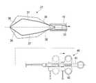
- the treatment tool 1 according to the present embodimentincludes a sheath 10, a wire 20, and an operation unit 40.
- the sheath 10has a longitudinal axis L and is inserted into a body cavity.
- the sheath 10is made of an insulating material, and is formed of, for example, an insulating resin.
- the sheath 10is formed of a flexible material so that the sheath 10 can advance and retreat in a channel of an endoscope or the like having a shape that follows the curvature of a luminal tissue or the like in a body cavity.
- the wire 20is inserted into the sheath 10 so as to be able to advance and retreat, and includes a loop portion 21 on the distal end side and an operation wire 22 on the proximal end side as shown in FIG.
- the wire 20is conductive and can be energized with a high-frequency current.
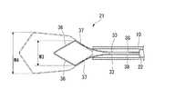
- the loop portion 21includes a first bent portion 31, a pair of second bent portions 32, and a pair of third bent portions 33 that are bent outwardly in a loop shape formed by the loop portion 21 from the distal end side to the proximal end side. It has in order toward.
- the loop portion 21includes a first region 36 between the first bent portion 31 and the second bent portion 32, a second region 37 between the second bent portion 32 and the third bent portion 33 adjacent to each other, It has the 3rd area
- the loop portion 21forms a substantially hexagonal loop formed symmetrically with respect to the longitudinal axis L.
- the loop portion 21is formed symmetrically with the longitudinal axis L in between, the shape on one side (upper side on the paper surface) will be described.
- the length L2 of the second region 37is longer than the length L1 of the first region 36 and the length L3 of the third region 38.
- the length L 3 of the third region 38is longer than the length L 1 of the first region 36.
- the angle ⁇ formed by the first region 36 and the second region 37 inside the loop portion 21is smaller than the angle ⁇ formed by the first region 36 and the longitudinal axis L on the tip side (outside of the loop).
- the angle ⁇is, for example, 100 degrees to 140 degrees.
- the pair of second regions 37are arranged in parallel, but in the present embodiment, since the angle ⁇ is smaller than the angle ⁇ , the second region 37 is in a non-parallel state.
- the length W1 between the pair of second bent portions 32 disposed with the longitudinal axis L interposed therebetweenis longer than the length W2 between the pair of third bent portions 33 disposed with the longitudinal axis L interposed therebetween.
- a loop portion 21is formed.
- the second region 37is inclined in a direction approaching the longitudinal axis L as it goes from the second bent portion 32 to the third bent portion 33.
- the angle formed between the second region 37 and the third region 38is increased, and therefore the angle ⁇ formed between the distal end surface 22a of the operation wire 22 and the third region 38 is set so that the pair of second regions 37 are arranged in parallel. Bigger than the case.
- the operation unit 40includes an operation unit main body 41 connected to the proximal end portion of the sheath 10, a slider 42 attached to the operation unit main body 41, and a connector 43.
- An operation wire 22is connected to the slider 42. Accordingly, the wire 20 is moved back and forth with respect to the sheath 10 by moving the slider 42 forward and backward with respect to the operation portion main body 41.
- the loop portion 21protrudes from the distal end of the sheath 10. Further, when the slider 42 is moved backward with respect to the operation portion main body 41, the loop portion 21 is accommodated in the sheath 10.
- the connector 43can be connected to a high frequency power supply device (not shown) and can supply a high frequency current to the operation wire 22. Since the operation wire 22 is electrically connected to the loop portion 21, the high-frequency current supplied from the high-frequency power supply device is transmitted to the loop portion 21 via the operation wire 22.
- the endoscopeis inserted into the body cavity by a known technique, the tip of the endoscope is guided to the target site to be treated, and the polyp that is the target site is captured in the field of view of the endoscope.
- the surgeoninserts the treatment tool 1 into the endoscope and protrudes from the endoscope, and then slides the slider 42 of the operation unit 40 shown in FIG.
- the operation wire 22 connected to the slider 42is pushed toward the distal end side with respect to the sheath 10 and moves.
- the entire loop portion 21protrudes from the distal end of the sheath 10, and the loop portion 21 is deformed so as to open into a hexagonal shape by a restoring force due to its own elasticity (first state).
- first statea restoring force due to its own elasticity
- the surgeonslides the slider 42 of the operation unit 40 toward the proximal end side with respect to the operation unit main body 41. Thereby, the proximal end side of the loop portion 21 is drawn into the sheath 10, and the root of the polyp P is bound by the loop portion 21.
- the high frequency power supply deviceis operated to supply high frequency current to the treatment instrument 1. A high-frequency current is applied to the loop portion 21, and the polyp P tightly bound by the loop portion 21 is incised while being cauterized.
- the operatormoves the slider 42 of the operation unit 40 from the state where all the loop portions 21 protrude from the distal end of the sheath 10 as shown in FIG.
- the base body 41is slid toward the base end side, and as shown in FIG.
- the proximal end side of the loop portion 21is gradually drawn into the sheath 10.
- the slider 42is slid to the proximal end side, as shown in FIG. 5, the third region 38, the third bent portion 33, and a part of the second region 37 are accommodated in the sheath 10 in order, and the loop portion 21. Becomes a rhombus (second state).
- the maximum dimension W3 of the loop portion 21 in the orthogonal direction perpendicular to the longitudinal axis L in the second state, particularly in a state where about half of the entire length of the loop portion 21 in the longitudinal axis L direction is drawn into the sheath 10is the first state. It is 40% to 60% of the maximum dimension W4 of the loop portion 21 in the orthogonal direction. In the present embodiment, the dimension W3 is 60% of the dimension W4. As shown in FIG. 6, the operator places the loop portion 21 in the second state and hangs it on the polyp P. After that, as in the case where the size of the polyp is large, a high-frequency current is passed through the loop portion 21 so that the polyp P bounded by the loop portion 21 is cut open.
- the length of the first region 56 and the length of the third region 58are longer than the length of the second region 57 as shown in FIG.
- a loop portion 50is formed so as to be long.
- the loop portionis compared to the total length of the loop portion 50 in the longitudinal axis L direction compared to the present embodiment.
- the opening width W5 of 50is small.
- the angle ⁇ 1 formed by the first region 56 and the second region 57is larger than the angle ⁇ of the loop portion 21 due to the relationship between the lengths of the first region 56, the second region 57, and the third region 58 described above. .
- the loop portion 50rapidly shrinks as shown in FIG.
- the dimension W6 when the third bent part 53 is accommodated in the sheath 10is 30% of the dimension W5 of the loop part 50 in the orthogonal direction in a state where all the loop parts 50 shown in FIG. To a small extent.
- the total length in the longitudinal axis L direction of the loop portion 50 with respect to the opening width W5is the length of the loop portion 21 with respect to the opening width W4 in this embodiment. It becomes longer than the entire length in the longitudinal axis L direction.
- the third region 58is drawn into the sheath 10 in order to capture a small polyp, the loop portion 50 is collapsed and becomes abruptly small, making it difficult to capture the polyp.
- the surrounding normal tissueis inserted into the loop 50 more than the capture of the large polyp.
- the angle ⁇ 1 formed by the first region 56 and the second region 57 of the conventional treatment instrumentis equal to the angle ⁇ formed by the loop portion 21 of the treatment instrument of the present embodiment (an angle smaller than the angle ⁇ 1).
- the angle ⁇ 1 formed between the distal end surface 22a1 of the operation wire 22a and the third region 58becomes small, and the loop opening width W6 when the third region 58 is drawn into the sheath 10 becomes abruptly smaller than the above.
- the angle ⁇ 1 of the conventional treatment toolis set.
- the corresponding angle ⁇is smaller than the angle ⁇ 1. Therefore, the loop portion 21 can be gradually reduced without being drawn into the sheath 10 abruptly to form a diamond-shaped loop portion 21.
- the dimension W3is 60% of the dimension W4. Therefore, the loop portion 21 is pulled into the sheath 10 until the second state is reached. But the loop doesn't get too small. Accordingly, in the case of a large polyp, the loop portion 21 can be set in the first state and the polyp P can be bound, and in the case of a small polyp, the loop portion 21 can be set in the second state and the polyp P can be bound. According to the size of the polyp P, the size of the loop of the loop portion 21 can be appropriately changed.
- the polyp P having a different sizecan be preferably captured without making the overall length of the loop portion 21 in the longitudinal axis L direction relative to the opening width W4 longer than that of the conventional loop portion 50.
- normal tissue around the polyp Pcan be prevented from entering the loop portion 21. Thereby, a lesioned part can be captured appropriately.
- the size of the loop portion 21can be adjusted by drawing the third region 38 into the sheath 10 according to the size of the polyp P. It is.
- the loop portion 21is formed so that the angle ⁇ is larger than the angle ⁇ . That is, since the second region 37 is inclined in the direction approaching the longitudinal axis L from the second bent portion 32 toward the third bent portion 33, the second region 37 is formed by the distal end surface 22 a of the operation wire 22 and the third region 38. The angle ⁇ is large. Thereby, since the operation resistance when the operation wire 22 is pulled into the sheath 10 is reduced, the loop portion 21 can be smoothly accommodated in the sheath 10. Further, since the length L3 of the third region 38 is longer than the length L1 of the first region 36, the angle ⁇ is smaller than when the length L3 of the third region 38 is shorter than the length L1 of the first region 36. can do. Accordingly, since the first region 36 rises with respect to the longitudinal axis L, there is an effect that even if the loop portion 21 is pulled into the sheath 10, the loop portion 21 is not easily crushed.
- the structure which does not flow a high frequency currentmay be sufficient.
- the angle ⁇ formed on the tip side (outside of the loop) between the first region 36 and the longitudinal axis Lis smaller than the angle ⁇ formed on the inside of the loop portion 21 between the first region 36 and the second region 37.
- the angle ⁇ and the angle ⁇may be the same.
- the length L3 of the third region 38is longer than the length L1 of the first region 36, the length L1 of the first region 36 may be longer than the length L3 of the third region 38.
- the loop portion 60includes a pair of second regions 67 instead of the pair of second regions 37 of the first embodiment, and a pair of third regions 68 instead of the pair of third regions 38 of the first embodiment. It has.
- the third region 68is curved so as to be convex toward the inside of the loop. Accordingly, the angle ⁇ formed between the distal end surface 22a of the operation wire 22 and the third region 68 is larger than when the third region 68 is in a straight line state.
- an angle ⁇ formed on the tip side (outside of the loop) between the first region 36 and the longitudinal axis Lis equal to an angle ⁇ formed on the inside of the loop portion 60 between the first region 36 and the second region 67. That is, the pair of second regions 67 are arranged in parallel with the longitudinal axis L in between.
- the third region 68is curved, the loop portion 60 forms a substantially hexagonal loop formed symmetrically with the longitudinal axis L in between.
- the slider 42when the slider 42 is slid to the proximal end side, as shown in FIG. 11, the third region 68, the third bent portion 33, and a part of the second region 67 are accommodated in the sheath 10 in order, and the loop portion 60. Becomes a rhombus (second state). Then, as in the first embodiment, a high-frequency current is passed through the loop portion 60, and the polyp P that is bound by the loop portion 60 is cut open.
- the maximum dimension W7 of the loop portion 60 in the orthogonal direction orthogonal to the longitudinal axis L in the second state, particularly in a state where about half of the entire length of the loop portion 60 in the longitudinal axis L direction is drawn into the sheath 10is the first implementation. Similarly to the form, it is 40% to 60% of the maximum dimension W8 of the loop portion 60 in the orthogonal direction in the first state.
- the operation wire 22since the angle ⁇ formed between the distal end surface 22a of the operation wire 22 and the third region 68 is larger than when the third region 68 is in a straight state, the operation wire 22 is sheathed. The operating resistance when retracting into 10 is reduced. For this reason, it becomes possible to accommodate the loop part 60 in the sheath 10 smoothly.
- the third region 68may be curved so as to protrude toward the inside of the loop in a state where the angle ⁇ is smaller than the angle ⁇ as in the first embodiment. Further, as in the first embodiment, the third region 68 may be in a straight state, and the pair of second regions 67 may be parallel.
- the length of the second regionis longer than the length of the first region and the length of the third region, and the angle formed between the first region and the longitudinal axis at the distal end side
- the angleis equal to or smaller than the angle formed inside the loop portion between the first region and the second region, the lesion site can be captured appropriately.
Landscapes
- Health & Medical Sciences (AREA)
- Life Sciences & Earth Sciences (AREA)
- Surgery (AREA)
- Molecular Biology (AREA)
- Engineering & Computer Science (AREA)
- Biomedical Technology (AREA)
- Heart & Thoracic Surgery (AREA)
- Medical Informatics (AREA)
- Nuclear Medicine, Radiotherapy & Molecular Imaging (AREA)
- Animal Behavior & Ethology (AREA)
- General Health & Medical Sciences (AREA)
- Public Health (AREA)
- Veterinary Medicine (AREA)
- Orthopedic Medicine & Surgery (AREA)
- Vascular Medicine (AREA)
- Surgical Instruments (AREA)
Abstract
Description
Translated fromJapanese 本発明は、処置具に関する。
本願は、2015年03月13日に、日本に出願された特願2015-051290号に基づき優先権を主張し、その内容をここに援用する。The present invention relates to a treatment tool.
This application claims priority based on Japanese Patent Application No. 2015-051290 filed in Japan on Mar. 13, 2015, the contents of which are incorporated herein by reference.
従来、医療分野等では、体腔内に挿入される挿入部の先端に、生体組織に対して処置を行う処置部が設けられた処置具として、例えば、ポリープ等の病変部位をスネアループで捕捉する処置具が開示されている(特許文献1から特許文献3参照)。Conventionally, in a medical field or the like, as a treatment tool provided with a treatment unit for treating a living tissue at the distal end of an insertion unit inserted into a body cavity, for example, a lesion site such as a polyp is captured by a snare loop. A treatment instrument is disclosed (see
特許文献1から特許文献3に記載の処置具に用いられるスネアループ(ワイヤ)は、先端側から順に第1屈曲部、第2屈曲部、及び第3屈曲部を有する六角形状である。スネアループの基端側は連結パイプにより結束され、シース内に進退可能に挿通されている。Snare loops (wires) used in the treatment instruments described in
特許文献1から特許文献3に記載のいずれのスネアループも、第1屈曲部から第2屈曲部までの長さ、第2屈曲部から第3屈曲部までの長さ及び第3屈曲部から連結パイプまでの長さのうち、第3屈曲部から連結パイプまでの長さが最も長い。これにより、小さなポリープから大きなポリープまでを捕捉可能であり、また、スネアループをシースに引き込むときの操作抵抗を抑えることを可能としている。Any of the snare loops described in
特許文献1から特許文献3に開示されている処置具では、ポリープ等の病変部位を捕捉する際に、詳細は後述するが、病変部位以外もスネアループ内に入り込んでしまう場合がある。
また、スネアループの一部をシース内に引き込んだ際、シースの長手軸に対して垂直方向のスネアループの大きさが急激に変化しやすく、スネアループの大きさの調整が煩雑である。In the treatment tools disclosed in
Further, when a part of the snare loop is drawn into the sheath, the size of the snare loop in the direction perpendicular to the longitudinal axis of the sheath is likely to change rapidly, and the adjustment of the size of the snare loop is complicated.
本発明は、このような問題点に鑑みてなされたものであって、病変部位を好適に捕捉可能な処置具の提供を目的とする。The present invention has been made in view of such problems, and an object of the present invention is to provide a treatment tool capable of suitably capturing a lesion site.
本発明の第1の態様に係る処置具は、長手軸を有するシースと、先端にループ形状を有して、前記シース内に進退可能に挿通され、前記ループ形状の外方に向かって凸に曲がった第1屈曲部と、一対の第2屈曲部と、一対の第3屈曲部とを先端から基端に向かって順に有するループ部を有するワイヤとを備え、前記ループ部において、前記一対の第2屈曲部から前記一対の第3屈曲部までの第2領域の長さが、前記第1屈曲部から前記一対の第2屈曲部までの第1領域の長さ及び前記一対の第3屈曲部から前記ループ部の基端までの第3領域の長さより長く、前記第1領域と前記第2領域とが前記ループ部の内側でなす角度が、前記第1領域と前記長手軸とが先端側でなす角度以下である。The treatment instrument according to the first aspect of the present invention has a sheath having a longitudinal axis, a loop shape at the tip, is inserted into the sheath so as to be able to advance and retract, and is convex toward the outside of the loop shape. A wire having a loop portion having a bent first bent portion, a pair of second bent portions, and a pair of third bent portions in order from the distal end toward the proximal end, and in the loop portion, The length of the second region from the second bent portion to the pair of third bent portions is the length of the first region from the first bent portion to the pair of second bent portions and the pair of third bent portions. Longer than the length of the third region from the base portion to the base end of the loop portion, the angle formed by the first region and the second region inside the loop portion is the tip of the first region and the longitudinal axis It is below the angle made on the side.
本発明の第2の態様に係る処置具によれば、上記第1の態様において、前記長手軸を挟んで配置された前記一対の前記第2屈曲部間の長さが、前記長手軸を挟んで配置された前記一対の前記第3屈曲部間の長さよりも長くてもよい。According to the treatment tool according to the second aspect of the present invention, in the first aspect, the length between the pair of second bent portions arranged with the longitudinal axis interposed therebetween sandwiches the longitudinal axis. It may be longer than the length between the pair of third bent portions arranged in the above.
本発明の第3の態様に係る処置具によれば、上記第1の態様において、前記ループ部において、前記第3領域ワイヤの長さが前記第1領域の長さより長くてもよい。According to the treatment tool according to the third aspect of the present invention, in the first aspect, in the loop portion, the length of the third region wire may be longer than the length of the first region.
本発明の第4の態様に係る処置具によれば、上記第1の態様において、前記ループ部の長手軸方向の全長に対して半分が前記シース内に引き込まれた状態における前記長手軸に直交する直交方向の前記ループ部ワイヤの最大寸法は、前記ループ部すべてが前記シースの先端から突出した状態における前記直交方向の前記ループ部ワイヤの最大寸法の40%~60%であってもよい。According to the treatment tool according to the fourth aspect of the present invention, in the first aspect, the half of the entire length of the loop portion in the longitudinal axis direction is perpendicular to the longitudinal axis in a state in which the half is drawn into the sheath. The maximum dimension of the loop part wire in the orthogonal direction may be 40% to 60% of the maximum dimension of the loop part wire in the orthogonal direction in a state where all the loop parts protrude from the distal end of the sheath.
本発明の第5の態様に係る処置具によれば、上記第1の態様において、前記第3領域が前記ループ部の内側に向かって凸となるように湾曲していてもよい。According to the treatment tool according to the fifth aspect of the present invention, in the first aspect, the third region may be curved so as to be convex toward the inside of the loop portion.
上記各態様によれば、ループ部において、第2領域の長さが、第1領域の長さ及び第3領域の長さより長く、第1領域と長手軸との先端側でのなす角度が、第1領域と第2領域とのループ部の内側でのなす角度以下であるため、病変部位を好適に捕捉可能である。According to each aspect described above, in the loop portion, the length of the second region is longer than the length of the first region and the length of the third region, and the angle formed on the tip side of the first region and the longitudinal axis is Since the angle is equal to or smaller than the angle formed inside the loop portion between the first region and the second region, the lesion site can be captured appropriately.
[第1実施形態]
本発明の第1実施形態に係る処置具について、図1から図8を参照して説明する。
本実施形態に係る処置具1は、図1に示すように、シース10と、ワイヤ20と、操作部40とを備えている。[First Embodiment]
A treatment tool according to a first embodiment of the present invention will be described with reference to FIGS.
As shown in FIG. 1, the
シース10は、長手軸Lを有し、体腔内に挿入される。また、シース10は絶縁性を有する素材からなり、例えば絶縁性の樹脂等によって形成されている。シース10は、体腔内で管腔組織等の湾曲に沿う形状となった内視鏡等のチャンネル内で進退できるように柔軟な素材により形成されている。The
ワイヤ20は、進退可能にシース10内に挿通されており、図2に示すように、先端側にループ部21と、基端側に操作ワイヤ22とを備えている。
ワイヤ20は、導電性を有し、高周波電流を通電可能である。
ループ部21は、自身が形成するループ形状の外方に向かって凸に曲がった第1屈曲部31、一対の第2屈曲部32、一対の第3屈曲部33とを先端側から基端側に向かって順に有している。The
The
The
ループ部21は、第1屈曲部31と第2屈曲部32との間の第1領域36と、互いに隣り合う第2屈曲部32と第3屈曲部33との間の第2領域37と、互いに隣り合う第3屈曲部33とループ部21の基端21aとの間の第3領域38とを有している。
ループ部21は、長手軸Lを挟んで対称に形成された略六角形状のループを形成している。The
The
以下の説明において、ループ部21は長手軸Lを挟んで対称に形成されているため、片側の形状(紙面上側)について説明する。
ループ部21において、第2領域37の長さL2は、第1領域36の長さL1及び第3領域38の長さL3より長い。また、ループ部21において、第3領域38の長さL3が、第1領域36の長さL1より長い。In the following description, since the
In the
第1領域36と第2領域37とがループ部21の内側でなす角度βは、第1領域36と長手軸Lとが先端側(ループの外側)でなす角度αより小さい。角度βは、例えば、100度~140度である。角度αが角度βと等しい場合、一対の第2領域37は平行に配置されるが、本実施形態では、角度βが角度αよりも小さいため、非平行状態となる。長手軸Lを挟んで配置された一対の第2屈曲部32間の長さW1が、長手軸Lを挟んで配置された一対の第3屈曲部33間の長さW2よりも長くなるようにループ部21が形成されている。これにより、第2領域37は、第2屈曲部32から第3屈曲部33に向かうにつれて長手軸Lに近づく方向に傾斜している。その結果、第2領域37と第3領域38とのなす角度が大きくなるため、操作ワイヤ22の先端面22aと第3領域38とのなす角度γは、一対の第2領域37が平行に配置されている場合に比べて大きい。The angle β formed by the
操作部40は、図1に示すように、シース10の基端部に接続された操作部本体41と、操作部本体41に取り付けられたスライダ42と、コネクタ43とを有している。
スライダ42には操作ワイヤ22が接続されている。これにより、スライダ42を操作部本体41に対して進退させることによって、シース10に対してワイヤ20が進退動作される。本実施形態では、スライダ42を操作部本体41に対して前進させるとシース10の先端からループ部21が突出される。また、スライダ42を操作部本体41に対して後退させるとシース10の内部にループ部21が収容される。
また、コネクタ43は、図示しない高周波電源装置に接続可能であり、操作ワイヤ22に高周波電流を供給可能としている。操作ワイヤ22はループ部21と電気的に接続されているため、高周波電源装置から供給された高周波電流は操作ワイヤ22を介してループ部21に伝達される。As shown in FIG. 1, the
An
The
次に、生体の上皮から膨隆したポリープを切除する際の本実施形態の処置具1の動作について説明する。
まず、図示しないが、周知の手技によって内視鏡を体腔内へ挿入し、処置を行う対象部位まで内視鏡の先端を案内し、内視鏡の視野内に対象部位であるポリープを捉える。
術者は、処置具1を内視鏡に挿入して、内視鏡から突出させた後、図1に示す操作部40のスライダ42を操作部本体41に対して先端側へスライドさせる。スライダ42に接続された操作ワイヤ22がシース10に対して先端側へ押され、移動する。シース10の先端からループ部21すべてが突出し、ループ部21は、自身の弾性による復元力により六角形状に開くように変形する(第1状態)。ポリープの大きさが大きい(例えば、10mm程度)場合、ループ部21を全開に開いた状態のまま、術者は、図3に示すように、ループ部21をポリープPに掛ける。Next, operation | movement of the
First, although not shown, the endoscope is inserted into the body cavity by a known technique, the tip of the endoscope is guided to the target site to be treated, and the polyp that is the target site is captured in the field of view of the endoscope.
The surgeon inserts the
続いて、術者は、操作部40のスライダ42を操作部本体41に対して基端側へスライドさせる。これにより、ループ部21の基端側がシース10内に引き込まれ、ループ部21によってポリープPの根元が緊縛される。
次に、高周波電源装置を操作して、処置具1へ高周波電流を給電する。ループ部21に高周波電流を通電させ、ループ部21によって緊縛されたポリープPは焼灼されながら切開される。Subsequently, the surgeon slides the
Next, the high frequency power supply device is operated to supply high frequency current to the
ポリープの大きさが小さい(例えば、5mm程度)場合、図1に示すように、ループ部21すべてがシース10の先端から突出している状態から、術者は、操作部40のスライダ42を操作部本体41に対して基端側へスライドさせ、図4に示すように、第3領域38の一部を引き込み始める。このとき、徐々にループ部21の基端側がシース10内に引き込まれる。さらに、スライダ42を基端側へスライドさせると、図5に示すように、第3領域38、第3屈曲部33、第2領域37の一部が順にシース10内に収容され、ループ部21の形状はひし形になる(第2状態)。When the size of the polyp is small (for example, about 5 mm), the operator moves the
第2状態、特にループ部21の長手軸L方向の全長に対して半分程度がシース10に引き込まれた状態における長手軸Lに直交する直交方向のループ部21の最大寸法W3は、第1状態における直交方向のループ部21の最大寸法W4の40%~60%である。本実施形態では、寸法W3は寸法W4の60%である。
図6に示すように、術者はループ部21を第2状態にしてポリープPに掛ける。その後は、上述したポリープの大きさが大きい場合と同様に、ループ部21に高周波電流を通電させ、ループ部21によって緊縛されたポリープPが切開される。The maximum dimension W3 of the
As shown in FIG. 6, the operator places the
従来の処置具では、小さなポリープから大きなポリープまでを捕捉可能とするために、図7に示すように、第1領域56の長さ及び第3領域58の長さが第2領域57の長さより長くなるように、ループ部50が形成されている。ループ部50の長手軸L方向の全長が、本実施形態の処置具1のループ部21と同一である場合、本実施形態と比べ、ループ部50の長手軸L方向の全長に対し、ループ部50の開き幅W5が小さい形状となる。
また、上述の第1領域56、第2領域57、第3領域58の長さの関係により第1領域56と第2領域57とのなす角β1の角度がループ部21の角度βより大きくなる。このため、第3領域58をシース10内に引き込み始めると、図8に示すように、ループ部50は急激に縮小する。
第3屈曲部53までがシース10内に収容されたときの寸法W6は、図7に示すループ部50全てがシース10の先端から突出した状態における直交方向のループ部50の寸法W5の30%程度に小さくなる。
したがって、従来の処置具は、ループ部50すべてをシース10から突出させた状態では、開き幅W5に対するループ部50の長手軸L方向の全長が、本実施形態における開き幅W4に対するループ部21の長手軸L方向の全長に比べて長くなる。これにより、大きなポリープを捕捉するときも、ポリープの周辺の正常な組織までループ部50内に入り込んでしまう。また、小さいポリープを捕捉するために、シース10内に第3領域58を引き込むとループ部50はつぶれ、急激に小さくなりポリープを捕捉しにくい。そこで、ループ部50全てをシース10から突出させた状態で小さいポリープを捕捉すると、大きいポリープの捕捉以上に周辺の正常組織までループ50内に入れ込んでしまう。
なお、従来の処置具の第1領域56と第2領域57とのなす角β1の角度を、本実施形態の処置具のループ部21のなす角βと同等の角度(角度β1より小さい角度)とした場合、操作ワイヤ22aの先端面22a1と第3領域58のなす角度γ1が小さくなり、第3領域58をシース10へ引き込んだときのループ開き幅W6が上述以上に急激に小さくなる。 In the conventional treatment instrument, in order to be able to capture from a small polyp to a large polyp, the length of the
Further, the angle β1 formed by the
The dimension W6 when the third
Therefore, in the conventional treatment instrument, in the state where the
Note that the angle β1 formed by the
本実施形態の処置具1によれば、第2領域37の長さL2が、第1領域36の長さL1及び第3領域38の長さL3より長いため、従来の処置具の角度β1に相当する角度βは、角度β1より小さくなる。したがって、ループ部21はシース10内に急激に引き込まれることなく、徐々に縮小し、ひし形形状のループ部21を形成することができる。According to the
また、ループ部21が第1状態であるときと、第2状態であるときとでは、寸法W3は寸法W4の60%であるため、第2状態になるまでループ部21をシース10内に引き込んでも、ループが過剰に小さくならない。これにより、大きいポリープの場合は、ループ部21を第1状態にして、ポリープPを緊縛し、小さいポリープの場合は、ループ部21を第2状態にして、ポリープPを緊縛することができるため、ポリープPの大きさに合わせて、適宜ループ部21のループの大きさを変えることができる。
この結果、開き幅W4に対するループ部21の長手軸L方向の全長を従来のループ部50に比べて長くしなくても、サイズの異なるポリープPを好適に捕捉することができる。その結果、ポリープPの周辺の正常な組織がループ部21内に入り込んでしまうのを防ぐことができる。これにより、病変部位を好適に捕捉することができる。In addition, when the
As a result, the polyp P having a different size can be preferably captured without making the overall length of the
さらに、ループ部21は急激にシース10内に引き込まれることがないため、ポリープPの大きさに合わせて第3領域38をシース10内に引き込み、ループ部21の大きさを調整することも可能である。Further, since the
さらに、角度αが角度βより大きくなるようにループ部21が形成されている。すなわち、第2領域37は、第2屈曲部32から第3屈曲部33に向かうにつれて長手軸Lに近づく方向に傾斜しているため、操作ワイヤ22の先端面22aと第3領域38とのなす角度γが大きい。これにより、操作ワイヤ22をシース10内に引き込むときの操作抵抗が小さくなるので、スムーズにループ部21をシース10内に収容することが可能となる。
また、第3領域38の長さL3が第1領域36の長さL1より長いため、第3領域38の長さL3が第1領域36の長さL1より短い場合に比べて角度αを小さくすることができる。これにより、長手軸Lに対して第1領域36が立ち上がっているため、ループ部21をシース10内に引き込んでも、ループ部21が潰れにくいという効果を奏する。Further, the
Further, since the length L3 of the
なお、処置具1のループ部21に高周波電流を流す構成にしたが、高周波電流を流さない構成であってもよい。
第1領域36と長手軸Lとの先端側(ループの外側)でのなす角度αが、第1領域36と第2領域37とのループ部21の内側でのなす角度βより小さいとしたが、角度αと角度βが同じであってもよい。
第3領域38の長さL3が、第1領域36の長さL1より長いとしたが、第1領域36の長さL1が第3領域38の長さL3より長くてもよい。In addition, although it was set as the structure which flows a high frequency current into the
The angle α formed on the tip side (outside of the loop) between the
Although the length L3 of the
[第2実施形態]
本発明の第2実施形態について、図9から図11を用いて説明する。
本実施形態の処置具では、ループ部の構成において第1実施形態と異なる。
以降の説明において、上述したものと共通の構成要素には同一の符号を付し、重複する説明を省略する。[Second Embodiment]
A second embodiment of the present invention will be described with reference to FIGS.
The treatment tool of the present embodiment is different from the first embodiment in the configuration of the loop portion.
In the following description, the same components as those described above are denoted by the same reference numerals, and redundant description is omitted.
ループ部60は、第1実施形態の一対の第2領域37に代えて、一対の第2領域67を備え、第1実施形態の一対の第3領域38に代えて、一対の第3領域68を備えている。The
第3領域68は、ループの内側に向かって凸となるように湾曲している。これにより、操作ワイヤ22の先端面22aと第3領域68とのなす角度γが、第3領域68が直線状態であるときに比べて大きい。
また、第1領域36と長手軸Lとの先端側(ループの外側)でのなす角度αが、第1領域36と第2領域67とのループ部60の内側でのなす角度βに等しい。すなわち、一対の第2領域67は長手軸Lを挟んで平行に配置されている。
ループ部60は、第3領域68が湾曲しているが、長手軸Lを挟んで対称に形成された略六角形状のループをなしている。The
In addition, an angle α formed on the tip side (outside of the loop) between the
Although the
次に、本実施形態の処置具を用いて、生体の上皮から膨隆したポリープを切除する方法について説明する。
図9に示すように、ループ部60すべてがシース10の先端から突出している状態(第1状態)から、術者は、操作部40のスライダ42を操作部本体41に対して基端側へスライドさせ、図10に示すように、第3領域68の一部を引き込み始める。このとき、第3領域68がループの内側に向かって凸となるように湾曲しているため、徐々にループ部60の基端側がシース10内に引き込まれる。さらに、スライダ42を基端側へスライドさせると、図11に示すように、第3領域68、第3屈曲部33、第2領域67の一部が順にシース10内に収容され、ループ部60の形状はひし形になる(第2状態)。そして、第1実施形態と同様に、ループ部60に高周波電流を通電させ、ループ部60によって緊縛されたポリープPが切開される。Next, a method for excising a polyp that bulges from the epithelium of a living body using the treatment tool of this embodiment will be described.
As shown in FIG. 9, from the state in which all the
第2状態、特にループ部60の長手軸L方向の全長に対して半分程度がシース10に引き込まれた状態における長手軸Lに直交する直交方向のループ部60の最大寸法W7は、第1実施形態と同様に、第1状態における直交方向のループ部60の最大寸法W8の40%~60%である。The maximum dimension W7 of the
本実施形態の処置具によれば、操作ワイヤ22の先端面22aと第3領域68とのなす角度γが、第3領域68が直線状態であるときに比べて大きいため、操作ワイヤ22をシース10内に引き込むときの操作抵抗が小さくなる。このため、スムーズにループ部60をシース10内に収容することが可能となる。According to the treatment instrument of the present embodiment, since the angle γ formed between the
なお、第1実施形態のように角度αが角度βより小さい状態で、第3領域68がループの内側に向かって凸となるように湾曲していてもよい。また、第1実施形態のように第3領域68が直線状態であって、一対の第2領域67が平行であってもよい。Note that the
以上、本発明の好ましい実施形態を説明したが、本発明はこれら実施形態に限定されることはない。本発明の趣旨を逸脱しない範囲で、構成の付加、省略、置換、およびその他の変更が可能である。本発明は前述した説明によって限定されることはなく、添付のクレームの範囲によってのみ限定される。The preferred embodiments of the present invention have been described above, but the present invention is not limited to these embodiments. Additions, omissions, substitutions, and other modifications can be made without departing from the spirit of the present invention. The present invention is not limited by the above description, but only by the scope of the appended claims.
上記各実施態様の処置具は、ループ部において、第2領域の長さが、第1領域の長さ及び第3領域の長さより長く、第1領域と長手軸との先端側でのなす角度が、第1領域と第2領域とのループ部の内側でのなす角度以下であるため、病変部位を好適に捕捉可能である。
In the treatment device of each of the above embodiments, in the loop portion, the length of the second region is longer than the length of the first region and the length of the third region, and the angle formed between the first region and the longitudinal axis at the distal end side However, since the angle is equal to or smaller than the angle formed inside the loop portion between the first region and the second region, the lesion site can be captured appropriately.
α 角度
β 角度
L 長手軸
L1 第1領域の長さ
L2 第2領域の長さ
L3 第3領域の長さ
W1 一対の第2屈曲部間の長さ
W2 一対の第3屈曲部間の長さ
20 ワイヤ
21,60 ループ部
31 第1屈曲部
32 第2屈曲部
33 第3屈曲部
36 第1領域
37,67 第2領域
38,68 第3領域α angle β angle L longitudinal axis L1 length of first region L2 length of second region L3 length of third region W1 length between a pair of second bent portions W2 length between a pair of third
Claims (5)
Translated fromJapanese先端にループ形状を有して、前記シース内に進退可能に挿通され、前記ループ形状の外方に向かって凸に曲がった第1屈曲部と、一対の第2屈曲部と、一対の第3屈曲部とを先端から基端に向かって順に有するループ部を有するワイヤとを備え、
前記ループ部において、前記一対の第2屈曲部から前記一対の第3屈曲部までの第2領域の長さが、前記第1屈曲部から前記一対の第2屈曲部までの第1領域の長さ及び前記一対の第3屈曲部から前記ループ部の基端までの第3領域の長さより長く、
前記第1領域と前記第2領域とが前記ループ部の内側でなす角度が、前記第1領域と前記長手軸とが先端側でなす角度以下である
処置具。A sheath having a longitudinal axis;
A loop shape at the tip, which is inserted into the sheath so as to be able to advance and retreat, is bent in a convex manner toward the outside of the loop shape, a pair of second bend portions, and a pair of third A wire having a loop portion having a bent portion in order from the distal end to the proximal end,
In the loop portion, the length of the second region from the pair of second bent portions to the pair of third bent portions is the length of the first region from the first bent portion to the pair of second bent portions. Longer than the length of the third region from the pair of third bent portions to the base end of the loop portion,
The treatment tool, wherein an angle formed between the first region and the second region on the inner side of the loop portion is equal to or less than an angle formed between the first region and the longitudinal axis on the distal end side.
請求項1に記載の処置具。The length between the pair of second bent portions disposed with the longitudinal axis interposed therebetween is longer than the length between the pair of third bent portions disposed with the longitudinal axis interposed therebetween. Treatment tool.
請求項1に記載の処置具。The treatment tool according to claim 1, wherein in the loop portion, the length of the third region is longer than the length of the first region.
請求項1に記載の処置具。The maximum dimension of the loop portion in the orthogonal direction perpendicular to the longitudinal axis in a state where half of the entire length in the longitudinal axis direction of the loop portion is drawn into the sheath is that all the loop portions are from the distal end of the sheath. The treatment instrument according to claim 1, wherein the treatment tool is 40% to 60% of the maximum dimension of the loop portion in the orthogonal direction in the protruding state.
請求項1に記載の処置具。The treatment tool according to claim 1, wherein the third region is curved so as to be convex toward the inside of the loop portion.
Priority Applications (4)
| Application Number | Priority Date | Filing Date | Title |
|---|---|---|---|
| CN201580057815.6ACN107106192B (en) | 2015-03-13 | 2015-11-06 | disposal device |
| EP15885563.5AEP3269316A4 (en) | 2015-03-13 | 2015-11-06 | Treatment instrument |
| JP2016553040AJP6072384B1 (en) | 2015-03-13 | 2015-11-06 | Treatment tool |
| US15/497,260US10226267B2 (en) | 2015-03-13 | 2017-04-26 | Treatment instrument |
Applications Claiming Priority (2)
| Application Number | Priority Date | Filing Date | Title |
|---|---|---|---|
| JP2015051290 | 2015-03-13 | ||
| JP2015-051290 | 2015-03-13 |
Related Child Applications (1)
| Application Number | Title | Priority Date | Filing Date |
|---|---|---|---|
| US15/497,260ContinuationUS10226267B2 (en) | 2015-03-13 | 2017-04-26 | Treatment instrument |
Publications (1)
| Publication Number | Publication Date |
|---|---|
| WO2016147471A1true WO2016147471A1 (en) | 2016-09-22 |
Family
ID=56918768
Family Applications (1)
| Application Number | Title | Priority Date | Filing Date |
|---|---|---|---|
| PCT/JP2015/081303CeasedWO2016147471A1 (en) | 2015-03-13 | 2015-11-06 | Treatment instrument |
Country Status (5)
| Country | Link |
|---|---|
| US (1) | US10226267B2 (en) |
| EP (1) | EP3269316A4 (en) |
| JP (1) | JP6072384B1 (en) |
| CN (1) | CN107106192B (en) |
| WO (1) | WO2016147471A1 (en) |
Cited By (4)
| Publication number | Priority date | Publication date | Assignee | Title |
|---|---|---|---|---|
| GB2565113A (en)* | 2017-08-02 | 2019-02-06 | Gyrus Medical Ltd | Electrosurgical instrument |
| WO2020217383A1 (en)* | 2019-04-25 | 2020-10-29 | オリンパス株式会社 | High-frequency treatment tool |
| USD903116S1 (en) | 2018-03-12 | 2020-11-24 | Olympus Corporation | Surgical snare |
| US11096714B2 (en) | 2017-06-13 | 2021-08-24 | Olympus Corporation | Endoscopic treatment tool |
Families Citing this family (3)
| Publication number | Priority date | Publication date | Assignee | Title |
|---|---|---|---|---|
| CN108175476B (en)* | 2017-12-29 | 2021-01-05 | 杭州安杰思医学科技股份有限公司 | Diameter-variable sleeving and taking device |
| RU2695750C1 (en)* | 2019-01-10 | 2019-07-25 | федеральное государственное бюджетное образовательное учреждение высшего образования "Башкирский государственный медицинский университет" Министерства здравоохранения Российской Федерации | Device for removal of stones from extrahepatic bileducts |
| US12029403B2 (en) | 2021-03-04 | 2024-07-09 | Carnelian Medical LLC | Snare device |
Citations (3)
| Publication number | Priority date | Publication date | Assignee | Title |
|---|---|---|---|---|
| JPH1156864A (en)* | 1997-08-19 | 1999-03-02 | Asahi Optical Co Ltd | Tip loop type endoscope treatment tool |
| JP2000041996A (en)* | 1998-07-27 | 2000-02-15 | Asahi Optical Co Ltd | High frequency snare for endoscope |
| US20050085808A1 (en)* | 2003-10-16 | 2005-04-21 | Nakao Naomi L. | Medical instrument with indented loop and associated method |
Family Cites Families (14)
| Publication number | Priority date | Publication date | Assignee | Title |
|---|---|---|---|---|
| DE2132808C3 (en)* | 1971-07-01 | 1981-10-29 | Deyhle, Peter, Dr.med., 8520 Erlangen | Device for the diathermic removal of growths |
| US5059199A (en)* | 1989-04-12 | 1991-10-22 | Olympus Optical Co., Ltd. | Treating device for endoscopes |
| JPH0871082A (en) | 1994-09-08 | 1996-03-19 | Olympus Optical Co Ltd | High frequency incision jig for endoscope |
| JP4076607B2 (en) | 1997-10-23 | 2008-04-16 | ペンタックス株式会社 | Endoscope snare |
| JP2000083964A (en) | 1998-09-14 | 2000-03-28 | Asahi Optical Co Ltd | Wire loop type treatment tool for endoscope |
| EP1294286B1 (en)* | 2001-01-08 | 2005-12-07 | Boston Scientific Limited | Retrieval basket with releasable tip |
| JP2004249093A (en)* | 2003-01-31 | 2004-09-09 | Olympus Corp | Basket forceps |
| US20070250012A1 (en)* | 2006-04-24 | 2007-10-25 | Ifung Lu | Medical instrument having a medical needle-knife |
| US8858567B2 (en)* | 2006-10-14 | 2014-10-14 | Rafic Saleh | Surgical retrieval device and method |
| US20090024138A1 (en)* | 2007-07-18 | 2009-01-22 | Rafic Saleh | Surgical retrieval device radially deployable from collapsed position to a snare or cauterization loop |
| CN102365058A (en)* | 2009-02-06 | 2012-02-29 | 奥林巴斯医疗株式会社 | handling tools |
| US9439750B2 (en)* | 2011-12-16 | 2016-09-13 | Stryker Corporation | Embolectomy cage |
| CN202619790U (en)* | 2012-04-11 | 2012-12-26 | 常州市久虹医疗器械有限公司 | Biliary tract stone dislodger with spring soft head |
| CN103654913A (en)* | 2012-09-25 | 2014-03-26 | 常州德天医疗器械有限公司 | Endoscope solid recycling device capable of being temporarily assembled |
- 2015
- 2015-11-06WOPCT/JP2015/081303patent/WO2016147471A1/ennot_activeCeased
- 2015-11-06CNCN201580057815.6Apatent/CN107106192B/enactiveActive
- 2015-11-06EPEP15885563.5Apatent/EP3269316A4/ennot_activeWithdrawn
- 2015-11-06JPJP2016553040Apatent/JP6072384B1/enactiveActive
- 2017
- 2017-04-26USUS15/497,260patent/US10226267B2/enactiveActive
Patent Citations (3)
| Publication number | Priority date | Publication date | Assignee | Title |
|---|---|---|---|---|
| JPH1156864A (en)* | 1997-08-19 | 1999-03-02 | Asahi Optical Co Ltd | Tip loop type endoscope treatment tool |
| JP2000041996A (en)* | 1998-07-27 | 2000-02-15 | Asahi Optical Co Ltd | High frequency snare for endoscope |
| US20050085808A1 (en)* | 2003-10-16 | 2005-04-21 | Nakao Naomi L. | Medical instrument with indented loop and associated method |
Non-Patent Citations (1)
| Title |
|---|
| See also references ofEP3269316A4* |
Cited By (6)
| Publication number | Priority date | Publication date | Assignee | Title |
|---|---|---|---|---|
| US11096714B2 (en) | 2017-06-13 | 2021-08-24 | Olympus Corporation | Endoscopic treatment tool |
| GB2565113A (en)* | 2017-08-02 | 2019-02-06 | Gyrus Medical Ltd | Electrosurgical instrument |
| GB2565113B (en)* | 2017-08-02 | 2022-06-15 | Gyrus Medical Ltd | Electrosurgical instrument |
| USD903116S1 (en) | 2018-03-12 | 2020-11-24 | Olympus Corporation | Surgical snare |
| USD1076083S1 (en) | 2018-03-12 | 2025-05-20 | Olympus Corporation | Surgical snare |
| WO2020217383A1 (en)* | 2019-04-25 | 2020-10-29 | オリンパス株式会社 | High-frequency treatment tool |
Also Published As
| Publication number | Publication date |
|---|---|
| US10226267B2 (en) | 2019-03-12 |
| JP6072384B1 (en) | 2017-02-01 |
| CN107106192B (en) | 2019-07-23 |
| US20170224365A1 (en) | 2017-08-10 |
| EP3269316A1 (en) | 2018-01-17 |
| JPWO2016147471A1 (en) | 2017-04-27 |
| CN107106192A (en) | 2017-08-29 |
| EP3269316A4 (en) | 2018-11-21 |
Similar Documents
| Publication | Publication Date | Title |
|---|---|---|
| JP6072384B1 (en) | Treatment tool | |
| JP4471125B2 (en) | High frequency treatment tool | |
| EP2052669B1 (en) | Endoscopic instrument and method for manufacturing thereof | |
| JP6761378B2 (en) | Endoscopic treatment tool | |
| JPWO2010090089A1 (en) | Treatment tool | |
| EP3222240A1 (en) | High frequency treatment tool and high frequency treatment system | |
| EP2111806B1 (en) | Endoscope treatment instrument | |
| US9782197B2 (en) | Tissue grasping device | |
| US10092307B2 (en) | Tissue grasping tool | |
| JP2006223640A (en) | Treatment device for endoscope | |
| JP2019000215A5 (en) | ||
| US7404817B2 (en) | High-frequency incision device | |
| JP5098024B2 (en) | Endoscopic high-frequency treatment instrument | |
| JP5186346B2 (en) | Endoscopic high-frequency snare | |
| JP4475991B2 (en) | Endoscopic high-frequency incision tool | |
| JP2009095451A (en) | Endoscope treatment tool | |
| JP4512723B2 (en) | Endoscope snare | |
| JP4388344B2 (en) | Endoscope snare | |
| JP4589511B2 (en) | Endoscopic high frequency snare | |
| JP4390510B2 (en) | Endoscopic high-frequency snare | |
| JP5235709B2 (en) | Endoscopic high-frequency treatment instrument | |
| WO2016199478A1 (en) | Endoscope | |
| JP2023140245A (en) | snare for endoscope | |
| JP4761597B2 (en) | Endoscopic high-frequency snare | |
| JP2004275641A (en) | High-frequency scalpel for endoscope |
Legal Events
| Date | Code | Title | Description |
|---|---|---|---|
| ENP | Entry into the national phase | Ref document number:2016553040 Country of ref document:JP Kind code of ref document:A | |
| 121 | Ep: the epo has been informed by wipo that ep was designated in this application | Ref document number:15885563 Country of ref document:EP Kind code of ref document:A1 | |
| NENP | Non-entry into the national phase | Ref country code:DE | |
| REEP | Request for entry into the european phase | Ref document number:2015885563 Country of ref document:EP |