WO2016127468A1 - Electronic cigarette atomizer with tobacco oil adjustment function - Google Patents
Electronic cigarette atomizer with tobacco oil adjustment functionDownload PDFInfo
- Publication number
- WO2016127468A1 WO2016127468A1PCT/CN2015/074675CN2015074675WWO2016127468A1WO 2016127468 A1WO2016127468 A1WO 2016127468A1CN 2015074675 WCN2015074675 WCN 2015074675WWO 2016127468 A1WO2016127468 A1WO 2016127468A1
- Authority
- WO
- WIPO (PCT)
- Prior art keywords
- sleeve
- atomizing
- opening
- oil
- electronic cigarette
- Prior art date
- Legal status (The legal status is an assumption and is not a legal conclusion. Google has not performed a legal analysis and makes no representation as to the accuracy of the status listed.)
- Ceased
Links
Images


Classifications
- A—HUMAN NECESSITIES
- A24—TOBACCO; CIGARS; CIGARETTES; SIMULATED SMOKING DEVICES; SMOKERS' REQUISITES
- A24F—SMOKERS' REQUISITES; MATCH BOXES; SIMULATED SMOKING DEVICES
- A24F40/00—Electrically operated smoking devices; Component parts thereof; Manufacture thereof; Maintenance or testing thereof; Charging means specially adapted therefor
- A24F40/40—Constructional details, e.g. connection of cartridges and battery parts
- A—HUMAN NECESSITIES
- A24—TOBACCO; CIGARS; CIGARETTES; SIMULATED SMOKING DEVICES; SMOKERS' REQUISITES
- A24F—SMOKERS' REQUISITES; MATCH BOXES; SIMULATED SMOKING DEVICES
- A24F15/00—Receptacles or boxes specially adapted for cigars, cigarettes, simulated smoking devices or cigarettes therefor
- A24F15/01—Receptacles or boxes specially adapted for cigars, cigarettes, simulated smoking devices or cigarettes therefor specially adapted for simulated smoking devices or cigarettes therefor
- A24F15/015—Receptacles or boxes specially adapted for cigars, cigarettes, simulated smoking devices or cigarettes therefor specially adapted for simulated smoking devices or cigarettes therefor with means for refilling of liquid inhalable precursors
- A—HUMAN NECESSITIES
- A24—TOBACCO; CIGARS; CIGARETTES; SIMULATED SMOKING DEVICES; SMOKERS' REQUISITES
- A24F—SMOKERS' REQUISITES; MATCH BOXES; SIMULATED SMOKING DEVICES
- A24F40/00—Electrically operated smoking devices; Component parts thereof; Manufacture thereof; Maintenance or testing thereof; Charging means specially adapted therefor
- A24F40/10—Devices using liquid inhalable precursors
Definitions
- the inventionrelates to an electronic cigarette and an accessory thereof, in particular to an electronic cigarette atomizer with a smoke oil regulating function.
- Electronic cigaretteis a common cigarette replacement product, generally including interconnected battery rods and electronic cigarettes, wherein the electronic cigarette atomizer generally comprises a tobacco pipe and an atomizer body, and the tobacco pipe provides smoke to the heat generating component through the oil guiding rope.
- the oil, the atomizer bodyis used to heat atomize the smoke oil in the pipe.
- the prior art electronic cigarette atomizerhas the following disadvantages: (1) In the electronic cigarette atomizer, the smoke oil supply structure for providing the smoke oil to the heat generating component through the oil guiding rope is a fixed structure, and the smoke oil cannot be realized.
- the oil supply size adjustment functionis a fixed structure, and the smoke oil cannot be realized.
- the oil pipeprovides the smoke oil to the heat generating component through the oil guiding rope, and the oil guiding rope in the oil guiding rope and the heat generating component is in contact with the air in the atomizing cavity of the atomizer body even when not in use, therefore
- the smoke absorbed by the aboveis easy to dry and leak, which causes the problem of the smoke and oil leakage of the electronic cigarette atomizer from the transportation and storage links before leaving the factory to the user;
- the pipe and the atomizationThe plug connection between the main bodies is not good, and it is easy to affect the normal oil supply between the pipe and the atomizer body.
- the technical problem to be solved by the present inventionis that, in view of the above problems of the prior art, a problem of preventing smoke from drying out and causing smoke oil leakage in the transportation and storage links of the electronic cigarette before reaching the user is provided, and the supply of the smoke oil can be realized.
- the oil volume adjustment function, the electronic cigarette atomizer with smoke and oil adjustment functionadjusted to the user's required amount of smoke and mouthfeel, firm and reliable, quick assembly, stable and flat connection, and simple structure.
- the technical solution adopted by the present inventionis:
- An electronic cigarette atomizer having a smoke oil regulating functioncomprising a rotary connecting oil pipe and an atomizer body, wherein the oil pipe is inserted with a sleeve, the sleeve end is closed and provided on the side wall a first opening, a tubular inner plug is fixed inside the sleeve, a second opening is arranged on a side of the inner sleeve on the first opening, and a built-in oil guiding rope is arranged on the atomizer body
- the cannulais closed, and the third end is provided on the side wall, and the cannula is inserted into the inner plug of the sleeve.
- the end of the oil pipeis provided with a connection opening
- the inner wall of the connection openingis provided with an introduction groove arranged along the axial direction of the pipe
- the inner wall of the connection openingis provided with a limit stop.
- the atomizer bodyis provided with at least two hooks, and the hooks are inserted into the connection openings along the introduction slots and are located inside the limit stops by the rotation.
- the bottom of the connecting openingis provided with an elastic element and a top pressing cover which are both annular, and the pressing cover is disposed on the outer side of the elastic element, and the end of the hook is in contact with the top pressing cover.
- the oil pipeis provided with a smoke oil chamber and an air flow passage, and one end of the oil oil chamber is provided with an opening, and the opening of the oil oil chamber is provided with a leakage preventing plug, and one end of the oil pipe is inserted
- the sleevehas a fixed inner sleeve, and the sleeve is disposed on the fixed inner sleeve, and the sleeve is inserted into the smoke oil cavity through the leakage preventing plug, and the end of the inner sleeve is provided with a fixed base, and the inner sleeve One end of the fixed base is provided with an anti-rotation positioning post, and the anti-rotation positioning post is inserted in the air flow passage.
- the atomizer bodycomprises an atomizing housing with an atomization chamber, the atomization chamber of the atomization housing is in communication with an air flow passage, the atomization housing is provided with an atomizing cover at one end and the other end is provided Rotating the base, the atomizing housing is inserted into the connecting opening, the rotating base is located outside the connecting opening, and the insertion tube is disposed on the atomizing cover and communicates with the atomizing chamber of the atomizing housing, the rotation An electrical connector is disposed on the base, and the atomizing housing is provided with a ceramic seat and a heat insulating member, and at least one heat generating component is disposed between the ceramic seat and the inner wall of the atomizing shell, the heat is generated The component is mounted on the ceramic holder, the heat generating component and the electrical connector are electrically connected, and the heat generating component is in contact with the oil guiding rope.
- the side of the atomization casing that is located on the rotating baseis provided with oil-repellent cotton.
- the electrical connectorincludes a threaded connection post, a spacer sleeve and a thimble, the spacer sleeve is inserted into the threaded connection post, the thimble is inserted into the isolation sleeve and insulated from the threaded connection post, the heat generating component
- the two connecting pinsrespectively pass through the grease dam, and one of the connecting pins is inserted between the threaded connecting post and the isolating sleeve, and the other connecting pin is inserted between the insulating sleeve and the thimble.
- the outer sleeve of the fixed inner sleeve and the tobacco pipeis provided with a reinforcing cover, and a first sealing ring is disposed between the reinforcing cover and the fixed inner sleeve.
- the end of the fixed inner sleeveis provided with an air intake decorative ring
- the outer wall of the air intake decorative ringis provided with a second air inlet hole
- the atomized outer casingis provided with a first communicating with the atomizing chamber
- An air inlet hole, the atomization cover sideis provided with an atomization air outlet communicating with the atomization chamber
- the second air inlet holesequentially passes through the first air inlet hole through the atomization chamber of the atomization housing and atomizes
- the vent holeis connected, and the oil pipe is further provided with a fueling hole, and the oiling hole is inserted into the oiling hole.
- the other end of the tobacco pipeis connected with a universal nozzle assembly
- the universal nozzle assemblyincludes an upper cover, a screw seat and a nozzle head
- the upper coveris connected with the oil pipe
- the screw seatis provided a rotating cavity
- the end of the nozzle headis provided with a rotating ball head
- the rotating ball headis disposed in the rotating cavity
- the rotating ball head and the rotating cavityare provided with a second sealing ring
- the nozzle headis located
- the outer sleeve of the rotating ball headis provided with a nozzle fixing cover, and the nozzle fixing cover is inserted and fixed in the rotating cavity.
- the inventioncomprises a rotary connected tobacco pipe and an atomizer body, wherein a sleeve is inserted in the tobacco pipe, the end of the sleeve is closed and a first opening is arranged on the side wall, and a tubular inner portion is fixed inside the sleeve a plug that has a first opening a second opening is arranged on the side;
- the atomizer bodyis provided with a cannula with a built-in oil guiding rope, the end of the cannula is closed and a third opening is arranged on the side wall, and the cannula is inserted into the inner sleeve of the sleeve
- the third openingis offset from the second opening, so that the size of the communication passage between the cannula and the inner tube of the tobacco pipe changes, on the one hand, at the factory.
- the third openingfaces the inner plug, so that the third opening is completely closed, thereby preventing the problem that the electronic cigarette smokes dry and the smoke oil leaks in the transportation and storage links before reaching the user.
- the inventionfurther has a connection opening at the end of the oil pipe, the inner wall of the connection opening is provided with an introduction groove arranged along the axial direction of the pipe, and the inner wall of the connection opening is provided with a limit stop, the atomizer body At least two hooks are provided, and the hooks are inserted into the connecting openings along the guiding slots and are located inside the limiting stops by the rotation. Inserting the hook along the introduction slot into the connection opening, and then pressing the atomizer body slightly and rotating to one side, the connection between the pipette and the atomizer body can be realized, and since the hook limit is at the limit stop at this time The inner side makes the hook hang on the lower end of the pipe, so the connection between the pipe and the atomizer body is more firm and reliable.
- the atomizer bodyis rotated to the other side, and the hook will leave the limit block.
- the inner sideis returned to the introduction groove, and the hook pipe is taken out along the introduction groove to separate the tobacco pipe and the atomizer body, thereby having the advantages of firmness, reliability, quick assembly, and simple structure.
- the present inventionfurther has a ring-shaped elastic element and a top pressure cover at the bottom of the connection opening, the top pressure cover is disposed on the outer side of the elastic element, and the end of the hook is in contact with the top pressure cover, when the hook is along the introduction groove
- the elastic elementis in a compressed state, the elastic element is pressed against the top cover, the top pressure cover is pressed and the pressure is transmitted, so that the smoke pipe
- the connection with the atomizer bodyis more flat and firm, and is not easy to loose.
- the inventionfurther comprises a smoke oil chamber and an air flow passage in the tobacco pipe, the end of the inner plug is provided with a fixed base, and one end of the fixed base is provided with an anti-rotation positioning column, and the anti-rotation positioning column is inserted in the air flow passage.
- the anti-rotation positioning postcan easily realize the fixing of the inner sleeve inside the sleeve, and ensure that the inner plug does not rotate when the rotation between the tobacco pipe and the atomizer body is rotated, thereby ensuring the adjustment of the rotating atomizer body.
- FIG. 1is a schematic diagram of a front view of an embodiment of the present invention.
- FIG. 2is a schematic side view showing the structure of the embodiment of the present invention.
- FIG. 3is a schematic cross-sectional view taken along line A-A of FIG. 2.
- FIG. 4is a schematic perspective view showing the structure of a pipe pipe portion in an embodiment of the present invention.
- Fig. 5is a top plan view showing the portion of the tobacco pipe in the embodiment of the present invention.
- Fig. 6is a bottom plan view showing the portion of the tobacco pipe in the embodiment of the present invention.
- Figure 7is a side elevational view showing the portion of the tobacco pipe portion of the embodiment of the present invention.
- Figure 8is a cross-sectional view showing the structure of Figure B-B.
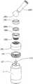
- FIG. 9is a perspective exploded view showing the tobacco pipe and the lower member in the portion of the tobacco pipe in the embodiment of the present invention.
- FIG. 10is a perspective exploded view showing the tobacco pipe and the upper part of the pipette portion in the embodiment of the present invention.
- Figure 11is a perspective view showing the structure of the atomizer body in the embodiment of the present invention.
- FIG. 12is a schematic diagram showing the structure of a main body of the atomizer body according to an embodiment of the present invention.
- FIG. 13is a schematic view showing the structure of a rear view body of the atomizer body according to an embodiment of the present invention.
- Figure 14is a cross-sectional view showing the structure of the C-C of Figure 13 and its gas flow direction.
- FIG. 15is a schematic exploded perspective view of the atomizer body according to an embodiment of the present invention.
- Figure 16is a schematic view showing the structure of a gas flow direction according to an embodiment of the present invention.
- the electronic cigarette atomizer having the smoke oil adjusting function of the embodimentincludes a rotary connecting oil pipe 1 and an atomizer body 2 , and the casing 10 is inserted into the tobacco pipe 1 .
- the end of the sleeve 10is closed and a first opening 101 is defined in the side wall.
- the sleeve 10is internally fixed with a tubular inner plug 102.
- the inner plug 102has a second opening on a side of the first opening 101.
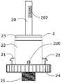
- the atomizer body 2is provided with a cannula 20 with a built-in oil guiding cord 201.
- the end of the cannula 20is closed and a third opening 202 is disposed on the side wall.
- the cannula 20is inserted into the inner sleeve of the sleeve 10.
- Plug 102When the atomizer body 2 is rotated, the third opening 202 is displaced relative to the second opening 103, so that the size of the communication passage between the cannula 20 and the inner cavity of the pipette 1 changes, on the one hand, at the factory.
- the third opening 202faces the inner plug 102, so that the third opening 202 is completely closed, thereby preventing the electronic cigarette from being dried and transported in the transportation and storage links before reaching the user.
- the inner plug 102is made of silica gel, and the inner plug 102 can also be made of rubber or other flexible materials as needed; the oil guiding rope 201 is specifically made of glass fiber rope, and other guides can also be used. Oil-functional fiber rope.
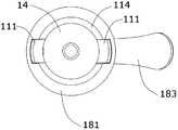
- the end portion of the soot pipe 1is provided with a connection opening 11, and the inner wall of the connection opening 11 is provided with an axis along the tobacco pipe 1.
- the inner wall of the connecting opening 11is provided with a limiting stopper 112.
- the atomizer body 2is provided with at least two hooks 21, and the hook 21 is inserted into the connecting opening 11 along the guiding slot 111 and passes through The rear limit of rotation is located inside the limit stop 112.
- the hook 21is inserted into the connection opening 11 along the introduction groove 111, and the atomizer body 2 is slightly pressed and rotated to one side (in this embodiment, specifically clockwise) to realize the pipette 1 and the atomizer.
- connection between the body 2 and the hook 21is limited to the inner side of the limiting block 112, so that the hook 21 is hung at the lower end of the tobacco pipe 1, so that the connection between the pipette 1 and the atomizer body 2 is more firm and reliable.
- the atomizer body 2is rotated to the other side (specifically, counterclockwise in this embodiment), and the hook 21 is returned from the inner side of the limit stop 112 to the introduction groove 111, and the hook 21 is guided along the introduction groove 111.
- the smoke pipe 1 and the atomizer body 2can be separated by extraction, so that the utility model has the advantages of firmness and reliability, quick assembly, and simple structure.
- the bottom of the connecting opening 11is provided with an elastic element 113 and a top pressing cover 114 which are both annular, and the top pressing cover 114 is disposed on the outer side of the elastic element 113, and the end of the hook 21 is in contact with each other.
- the top cover 114On the top cover 114.
- the cover 114is forced to press and press the hook 21, so that the connection between the pipette 1 and the atomizer body 2 is more flat and firm, and is not easy to loosen.
- the elastic member 113is made of silica gel.
- the elastic member 113can also be made of elastic elastic members such as rubber as needed, and elastic elastic members such as springs can be used as needed. element.
- the tobacco oil pipe 1is provided with a smoke oil chamber 12 and an air flow passage 13, and one end of the oil oil chamber 12 is provided with an opening, and the opening of the oil oil chamber 12 is provided.
- a leakage preventing plug 121is disposed, and one end of the oil pipe 1 is inserted with a fixed inner sleeve 14 , and the sleeve 10 is disposed on the fixed inner sleeve 14 , and the sleeve 10 is inserted into the smoke oil chamber 12 through the leakage preventing plug 121 ,
- the end of the inner plug 102is provided with a fixed base 104, and one end of the fixed base 104 is provided with an anti-rotation positioning post 105, and the anti-rotation positioning post 105 is inserted into the airflow passage 13.
- the inner sleeve 102can be simply fixed inside the sleeve 10 by the anti-rotation positioning post 105, and the inner plug 102 does not rotate when the rotation between the tobacco tube 1 and the atomizer body 2 is ensured. It is ensured that the rotation of the atomizer body 2 adjusts the reliability of the size of the communication passage between the cannula 20 and the lumen of the tobacco pipe 1.
- the leakage preventing plug 121is made of silica gel, and the leakage preventing plug 121 can also be made of rubber as needed.
- the atomizer body 2includes an atomizing casing 22 with an atomizing chamber, and the atomizing chamber of the atomizing casing 22 communicates with the gas flow passage 13, mist.
- the outer casing 22is provided with an atomizing cover 23 at one end and a rotating base 24 at the other end. The atomizing outer casing 22 is inserted into the connecting opening 11, the rotating base 24 is located outside the connecting opening 11, and the cannula 20 is disposed on the atomizing cover.
- the heat generating component 26is disposed on the ceramic seat 221, the heat generating component 26 and the electrical connector 25 are electrically connected to each other, and the heat generating component 26 is in contact with the oil guiding wire 201.
- the member 222is disposed between the ceramic seat 221 and the inner wall of the atomizing housing 22. .
- the rotating base 24Since the atomizing housing 22 is inserted into the connecting opening 11, the rotating base 24 is located outside the connecting opening 11, so that the tobacco pipe 1 and the atomizer body 2 are in a connected state, and the atomizer can be conveniently rotated by the rotating base 24.
- the body 2on the one hand, makes it easier to rotate the rotating base 24 to completely close the third opening 202 or to adjust the size of the communication passage between the cannula 20 and the inner portion of the tubing 1.
- the hook 21is also It is also more convenient when the introduction groove 111 is inserted into the connection opening 11 and the rotation limit is located inside the limit stopper 112.
- a double heat generating structureis formed by the two heat generating components 26, and the oil guiding rope 201 is interposed between the two heat generating components 26, and the heating efficiency is higher; no doubt, in this embodiment, only two heat generating components are used.
- 26is exemplified, and in addition, a heat generating component 26 or more heat generating components 26 may be employed as needed.
- the heat generating component 26includes a fiberglass rope and a heating wire wound around the fiberglass rope.
- the fiberglass ropeis mounted on the ceramic seat 221, and the fiberglass rope and the oil guiding rope 201 have the same function and are used for the oil guiding rope 201.
- the smoky oilis conducted to the heating wire wound around the fiberglass rope; there is no doubt that the function of the heat generating component 26 is for heating the smoky oil, and other structures capable of heating the smoky oil may be used as needed.
- the oil mist 223is provided on the side of the atomizing casing 22 which is adjacent to the rotating base 24.
- the oil-repellent cotton 223can isolate the side of the atomizing casing 22 from the side of the rotating base 24 to prevent oil from flowing out of the rotating base 24 from the side of the rotating base 24, so that the atomizer body 2
- the oil leakage prevention effectis better.
- the electrical connector 25includes a threaded connection post 251, a spacer sleeve 252 and a thimble 253.
- the spacer sleeve 252is inserted into the threaded connection post 251, and the thimble 253 is inserted into the spacer sleeve 252 and is threaded.
- the connecting post 251is insulated, and the two connecting pins of the heat generating component 26 respectively pass through the grease ray 223, and one connecting pin is interposed between the screw connecting post 251 and the spacer sleeve 252 (ie, the contact with the screw connecting post 251 is achieved).
- the other pinis interposed between the spacer sleeve 252 and the thimble 253 (ie, in contact with the thimble 253).
- the electrical connector 25can realize the mechanical structure connection between the embodiment and the battery rod based on the structure of the above-mentioned thread form, and can realize the electrical connection between the embodiment and the battery rod, and has a firm and reliable connection and stable electrical contact. Good sex.
- the spacer sleeve 252is made of silica gel.
- the spacer sleeve 252can also be made of rubber or other material having an insulating function as needed; the screw connection post 251 and the thimble 253 are made of metal.
- the two connecting pins of the heat generating component 26respectively pass through the grease ray 223, and one connecting pin is inserted between the threaded connecting post 251 and the spacer sleeve 252 (ie, with the thread
- the connection post 251realizes contact conduction
- the other connection pinis inserted between the isolation sleeve 252 and the ejector pin 253 (ie, the contact with the ejector pin 253 is achieved), and the above structure does not need to be soldered, so soldering is not required, and the connection is more environmentally friendly.
- the assemblyis simpler; in this embodiment, the thimble 253 serves as the positive pole of the power source, and the screw connection post 251 serves as the negative pole of the power source.
- the outer sleeve 14 and the outer portion of the tobacco pipe 1are sleeved with a reinforcing cover 15 , and a first sealing ring 151 is disposed between the reinforcing cover 15 and the fixed inner sleeve 14 , which can increase the fixing inside.
- the strength of the joint between the sleeve 14 and the pipette 1ensures the sealing performance of the joint between the fixed inner casing 14 and the pipette 1.
- the end of the fixed inner sleeve 14is provided with an air intake decorative ring 16, and the outer wall of the air intake decorative ring 16 is provided with a second air inlet hole 161, as shown in FIG.
- the atomizing housing 22is provided with a first air inlet 220 communicating with the atomizing chamber, and the atomizing cover 23 is provided with an atomizing chamber.
- the atomized air outlet 231 and the second air inlet 161are sequentially communicated through the first air inlet 220 through the atomization chamber of the atomization housing 22 and the atomization air outlet 231.
- the structurecan realize the atomization of the atomization housing 22.
- the cavityrealizes rapid intake, and other forms of intake passage structure can also be adopted as needed;
- the oil pipe 1is further provided with a fueling hole 17, and the oiling hole 17 is inserted with a fueling plug 171 to ensure that the user can conveniently use the oil pipe 1 Adding smoke oil, so that the embodiment can be recycled, and the use cost is lower.
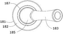
- FIG. 1the other end of the oil pipe 1 is connected with a universal nozzle assembly 18; as shown in FIG. 4, FIG. 5, FIG. 6, FIG. 7, FIG. 8 and FIG.
- the nozzle assembly 18includes an upper cover 181, a screw seat 182 and a nozzle head 183.
- the upper cover 181is connected to the tobacco pipe 1.
- the screw seat 182is provided with a rotating cavity 184.
- the end of the nozzle head 183is provided with a rotating ball head 185.
- the ball head 185is disposed in the rotating cavity 184, and a second sealing ring 186 is disposed between the rotating ball head 185 and the rotating cavity 184.
- the nozzle head 183is disposed on the outer side of the rotating ball head 185 with a nozzle fixing cover 187.
- the mouth fixing cover 187is inserted and fixed in the rotating cavity 184.
- the 360° multi-directional adjustmentcan be realized by the universal nozzle assembly 18, so that the use posture of the electronic cigarette is more flexible and more interesting, and the above structure can ensure the airtightness with the smoke pipe 1.
- the upper cover 181 and the tobacco pipe 1are connected by a threaded connection.
- the end of the oil pipe 1is provided with an externally threaded sleeve 19, and the upper cover 181 is provided with an internally threaded hole, and the externally threaded sleeve 19 and the internal thread on the upper cover 181 threaded connection; in addition, the upper cover 181 and the pipette 1 can also be connected by means of plug connection, bonding or the like.
- the flow of gas in the working state of the electronic cigarette atomizer having the smoke oil regulating function of the present embodimentcan be seen by the arrows in FIGS. 14 and 16: in the smoking state, the external pressure generated by the smoker sucks the outside.
- the airenters the connection opening 11 from the second air inlet hole 161 on the side wall of the air intake trim ring 16, and then enters the ceramic seat 221 from the first air inlet hole 220 on the atomizing outer casing 22 (ie, the atomizer body 2)
- the atomization chamberflows the smoke generated by the heat generating component 26 in the ceramic seat 221 through the atomizing air outlet 231 formed by the notch of the atomizing cover 23, enters the air flow passage 13 on the tobacco pipe 1, and then enters the screw seat 182. Rotating the cavity 184 and passing through the nozzle head 183 into the mouth of the smoker. Become a cigarette.
Landscapes
- Nozzles (AREA)
- Catching Or Destruction (AREA)
Abstract
Description
Translated fromChinese本发明涉及电子烟及其配件,具体涉及一种具有烟油调节功能的电子烟雾化器。The invention relates to an electronic cigarette and an accessory thereof, in particular to an electronic cigarette atomizer with a smoke oil regulating function.
电子烟是一种常见的香烟替代产品,一般包括相互连接的电池杆和电子烟雾化器,其中电子烟雾化器一般包括烟油管和雾化器本体,烟油管通过导油绳为发热组件提供烟油,雾化器本体用于将烟油管中的烟油进行加热雾化。但是,现有技术的电子烟雾化器存在下述缺点:(1)电子烟雾化器中,烟油管通过导油绳为发热组件提供烟油的烟油供给结构为固定结构,不能够实现烟油的供油量大小调节功能。(2)烟油管通过导油绳为发热组件提供烟油,其即使在不使用状态下,导油绳和发热组件中的导油绳在雾化器本体的雾化腔内和空气接触,因此使得上面吸收的烟油容易干涸以及泄漏,导致电子烟雾化器的烟油在出厂后至到达用户之前的运输、存储环节发生烟油干涸以及烟油泄漏的问题;(3)烟油管和雾化器本体之间的采用插接连接,连接牢固度欠佳,而且容易影响烟油管和雾化器本体之间的正常供油。Electronic cigarette is a common cigarette replacement product, generally including interconnected battery rods and electronic cigarettes, wherein the electronic cigarette atomizer generally comprises a tobacco pipe and an atomizer body, and the tobacco pipe provides smoke to the heat generating component through the oil guiding rope. The oil, the atomizer body is used to heat atomize the smoke oil in the pipe. However, the prior art electronic cigarette atomizer has the following disadvantages: (1) In the electronic cigarette atomizer, the smoke oil supply structure for providing the smoke oil to the heat generating component through the oil guiding rope is a fixed structure, and the smoke oil cannot be realized. The oil supply size adjustment function. (2) the oil pipe provides the smoke oil to the heat generating component through the oil guiding rope, and the oil guiding rope in the oil guiding rope and the heat generating component is in contact with the air in the atomizing cavity of the atomizer body even when not in use, therefore The smoke absorbed by the above is easy to dry and leak, which causes the problem of the smoke and oil leakage of the electronic cigarette atomizer from the transportation and storage links before leaving the factory to the user; (3) the pipe and the atomization The plug connection between the main bodies is not good, and it is easy to affect the normal oil supply between the pipe and the atomizer body.
【发明内容】[Summary of the Invention]
本发明要解决的技术问题是:针对现有技术的上述问题,提供一种能够防止电子烟在到达用户之前的运输、存储环节发生烟油干涸以及烟油泄漏的问题,能够实现烟油的供油量大小调节功能、调节至用户所需的烟雾量及口感、牢固可靠、组装快捷、连接稳定平整、结构简单的具有烟油调节功能的电子烟雾化器。The technical problem to be solved by the present invention is that, in view of the above problems of the prior art, a problem of preventing smoke from drying out and causing smoke oil leakage in the transportation and storage links of the electronic cigarette before reaching the user is provided, and the supply of the smoke oil can be realized. The oil volume adjustment function, the electronic cigarette atomizer with smoke and oil adjustment function adjusted to the user's required amount of smoke and mouthfeel, firm and reliable, quick assembly, stable and flat connection, and simple structure.
为了解决上述技术问题,本发明采用的技术方案为:In order to solve the above technical problems, the technical solution adopted by the present invention is:
一种具有烟油调节功能的电子烟雾化器,包括转动连接的烟油管和雾化器本体,所述烟油管中插设有套管,所述套管端部封闭且在侧壁上设有第一开口,所述套管内部固定有呈管状的内套塞,所述内套塞上靠第一开口的一侧设有第二开口;所述雾化器本体上设有内置导油绳的插管,所述插管端部封闭且在侧壁上设有第三开口,所述插管插设于套管的内套塞中。An electronic cigarette atomizer having a smoke oil regulating function, comprising a rotary connecting oil pipe and an atomizer body, wherein the oil pipe is inserted with a sleeve, the sleeve end is closed and provided on the side wall a first opening, a tubular inner plug is fixed inside the sleeve, a second opening is arranged on a side of the inner sleeve on the first opening, and a built-in oil guiding rope is arranged on the atomizer body The cannula is closed, and the third end is provided on the side wall, and the cannula is inserted into the inner plug of the sleeve.
优选地,所述烟油管的端部设有连接开口,所述连接开口的内壁上设有沿烟油管的轴向布置的导入槽,所述连接开口的内壁上设有限位挡块,所述雾化器本体上设有至少两个挂钩,所述挂钩沿着导入槽插设于连接开口内且通过转动后限位于限位挡块的内侧。Preferably, the end of the oil pipe is provided with a connection opening, the inner wall of the connection opening is provided with an introduction groove arranged along the axial direction of the pipe, and the inner wall of the connection opening is provided with a limit stop. The atomizer body is provided with at least two hooks, and the hooks are inserted into the connection openings along the introduction slots and are located inside the limit stops by the rotation.
优选地,所述连接开口的底部设有均呈环形的弹力元件和顶压盖,所述顶压盖设于弹力元件的外侧,所述挂钩的端部抵触在顶压盖上。Preferably, the bottom of the connecting opening is provided with an elastic element and a top pressing cover which are both annular, and the pressing cover is disposed on the outer side of the elastic element, and the end of the hook is in contact with the top pressing cover.
优选地,所述烟油管内设有烟油腔和气流通道,所述烟油腔的一端设有开口,所述烟油腔的开口处设有防漏塞,所述烟油管的一端插设有固定内套,所述套管设于固定内套上,且所述套管贯穿防漏塞后插设于烟油腔内,所述内套塞的端部设有固定底座,且所述固定底座的一端设有防转动定位柱,所述防转动定位柱插设于气流通道内。Preferably, the oil pipe is provided with a smoke oil chamber and an air flow passage, and one end of the oil oil chamber is provided with an opening, and the opening of the oil oil chamber is provided with a leakage preventing plug, and one end of the oil pipe is inserted The sleeve has a fixed inner sleeve, and the sleeve is disposed on the fixed inner sleeve, and the sleeve is inserted into the smoke oil cavity through the leakage preventing plug, and the end of the inner sleeve is provided with a fixed base, and the inner sleeve One end of the fixed base is provided with an anti-rotation positioning post, and the anti-rotation positioning post is inserted in the air flow passage.
优选地,所述雾化器本体包括带有雾化腔的雾化外壳,所述雾化外壳的雾化腔和气流通道连通,所述雾化外壳一端设有雾化盖、另一端设有转动基座,所述雾化外壳插设于连接开口内,所述转动基座位于连接开口外,所述插管设于雾化盖上且与雾化外壳的雾化腔连通,所述转动基座上设有电连接器,所述雾化外壳内设有陶瓷座和隔热件以及至少一个发热组件,所述隔热件布置于陶瓷座和雾化外壳的内壁之间,所述发热组件装设于陶瓷座上,所述发热组件和电连接器电连接导通,所述发热组件和导油绳接触。Preferably, the atomizer body comprises an atomizing housing with an atomization chamber, the atomization chamber of the atomization housing is in communication with an air flow passage, the atomization housing is provided with an atomizing cover at one end and the other end is provided Rotating the base, the atomizing housing is inserted into the connecting opening, the rotating base is located outside the connecting opening, and the insertion tube is disposed on the atomizing cover and communicates with the atomizing chamber of the atomizing housing, the rotation An electrical connector is disposed on the base, and the atomizing housing is provided with a ceramic seat and a heat insulating member, and at least one heat generating component is disposed between the ceramic seat and the inner wall of the atomizing shell, the heat is generated The component is mounted on the ceramic holder, the heat generating component and the electrical connector are electrically connected, and the heat generating component is in contact with the oil guiding rope.
优选地,所述雾化外壳内靠转动基座的一侧设有隔油棉。Preferably, the side of the atomization casing that is located on the rotating base is provided with oil-repellent cotton.
优选地,所述电连接器包括螺纹连接柱、隔离套和顶针,所述隔离套插设于螺纹连接柱中,所述顶针插设于隔离套中且与螺纹连接柱绝缘,所述发热组件的两个连接引脚分别穿过隔油棉,且一个所述连接引脚插设于螺纹连接柱和隔离套之间,另一个所述连接引脚插设于隔离套和顶针之间。Preferably, the electrical connector includes a threaded connection post, a spacer sleeve and a thimble, the spacer sleeve is inserted into the threaded connection post, the thimble is inserted into the isolation sleeve and insulated from the threaded connection post, the heat generating component The two connecting pins respectively pass through the grease dam, and one of the connecting pins is inserted between the threaded connecting post and the isolating sleeve, and the other connecting pin is inserted between the insulating sleeve and the thimble.
优选地,所述固定内套和烟油管的外部套设有加固罩,所述加固罩和固定内套之间设有第一密封圈。Preferably, the outer sleeve of the fixed inner sleeve and the tobacco pipe is provided with a reinforcing cover, and a first sealing ring is disposed between the reinforcing cover and the fixed inner sleeve.
优选地,所述固定内套的端部设有进气装饰环,所述进气装饰环的外壁上设有第二进气孔,所述雾化外壳上设有与雾化腔连通的第一进气孔,所述雾化盖一侧设有与雾化腔连通的雾化出气孔,所述第二进气孔依次通过第一进气孔通过雾化外壳的雾化腔和雾化出气孔连通,所述烟油管上还设有加油孔,所述加油孔中插设有加油塞。Preferably, the end of the fixed inner sleeve is provided with an air intake decorative ring, the outer wall of the air intake decorative ring is provided with a second air inlet hole, and the atomized outer casing is provided with a first communicating with the atomizing chamber An air inlet hole, the atomization cover side is provided with an atomization air outlet communicating with the atomization chamber, and the second air inlet hole sequentially passes through the first air inlet hole through the atomization chamber of the atomization housing and atomizes The vent hole is connected, and the oil pipe is further provided with a fueling hole, and the oiling hole is inserted into the oiling hole.
优选地,所述烟油管的另一端连接有万向吸嘴组件,所述万向吸嘴组件包括上盖、螺杆座和吸嘴头,所述上盖和烟油管相连,所述螺杆座上设有转动腔,所述吸嘴头的端部设有转动球头,所述转动球头设于转动腔内,且转动球头、转动腔之间设有第二密封圈,所述吸嘴头上位于转动球头的外侧套设有吸嘴固定盖,所述吸嘴固定盖插设固定于转动腔内。Preferably, the other end of the tobacco pipe is connected with a universal nozzle assembly, the universal nozzle assembly includes an upper cover, a screw seat and a nozzle head, and the upper cover is connected with the oil pipe, and the screw seat is provided a rotating cavity, the end of the nozzle head is provided with a rotating ball head, the rotating ball head is disposed in the rotating cavity, and the rotating ball head and the rotating cavity are provided with a second sealing ring, and the nozzle head is located The outer sleeve of the rotating ball head is provided with a nozzle fixing cover, and the nozzle fixing cover is inserted and fixed in the rotating cavity.
本发明具有烟油调节功能的电子烟雾化器具有下述优点:The electronic cigarette atomizer with the smoke oil regulating function of the invention has the following advantages:
1、本发明包括转动连接的烟油管和雾化器本体,烟油管中插设有套管,套管端部封闭且在侧壁上设有第一开口,套管内部固定有呈管状的内套塞,内套塞上靠第一开口的一侧设有第二开口;雾化器本体上设有内置导油绳的插管,插管端部封闭且在侧壁上设有第三开口,插管插设于套管的内套塞中,基于上述结构,当转动雾化器本体时,则会使得第三开口相对第二开口发生偏移,从而使得插管和烟油管内腔之间的连通通道的大小发生变化,一方面在出厂时,可以方便地转动雾化器本体将第三开口面对内套塞,使得第三开口完全封闭,从而防止电子烟在到达用户之前的运输、存储环节发生烟油干涸以及烟油泄漏的问题;另一方面在使用时,可以方便地转动雾化器本体调节插管和烟油管内腔之间连通通道的大小,从而能够实现烟油的供油量大小调节功能,从而调节至用户所需的烟雾量及口感。1. The invention comprises a rotary connected tobacco pipe and an atomizer body, wherein a sleeve is inserted in the tobacco pipe, the end of the sleeve is closed and a first opening is arranged on the side wall, and a tubular inner portion is fixed inside the sleeve a plug that has a first openinga second opening is arranged on the side; the atomizer body is provided with a cannula with a built-in oil guiding rope, the end of the cannula is closed and a third opening is arranged on the side wall, and the cannula is inserted into the inner sleeve of the sleeve According to the above structure, when the atomizer body is rotated, the third opening is offset from the second opening, so that the size of the communication passage between the cannula and the inner tube of the tobacco pipe changes, on the one hand, at the factory. When the atomizer body is conveniently rotated, the third opening faces the inner plug, so that the third opening is completely closed, thereby preventing the problem that the electronic cigarette smokes dry and the smoke oil leaks in the transportation and storage links before reaching the user. On the other hand, when in use, it is convenient to rotate the atomizer body to adjust the size of the communication passage between the cannula and the inner tube of the tobacco pipe, thereby realizing the adjustment function of the oil supply amount of the smoke oil, thereby adjusting to the user's needs The amount of smoke and the taste.
2、本发明进一步在烟油管的端部设有连接开口,连接开口的内壁上设有沿烟油管的轴向布置的导入槽,连接开口的内壁上设有限位挡块,雾化器本体上设有至少两个挂钩,挂钩沿着导入槽插设于连接开口内且通过转动后限位于限位挡块的内侧。将挂钩沿着导入槽插入连接开口,再将雾化器本体稍用力挤压并向一侧转动,即可实现烟油管和雾化器本体的连接,而且由于此时挂钩限位于限位挡块的内侧,使得挂钩挂在烟油管的下端,因此烟油管和雾化器本体之间的连接更加牢固可靠,此时将雾化器本体向另一侧转动,则挂钩会离开限位挡块的内侧回到导入槽中,将挂钩沿导入槽抽出即可将烟油管和雾化器本体分离,因此具有牢固可靠、组装快捷、结构简单的优点。2. The invention further has a connection opening at the end of the oil pipe, the inner wall of the connection opening is provided with an introduction groove arranged along the axial direction of the pipe, and the inner wall of the connection opening is provided with a limit stop, the atomizer body At least two hooks are provided, and the hooks are inserted into the connecting openings along the guiding slots and are located inside the limiting stops by the rotation. Inserting the hook along the introduction slot into the connection opening, and then pressing the atomizer body slightly and rotating to one side, the connection between the pipette and the atomizer body can be realized, and since the hook limit is at the limit stop at this time The inner side makes the hook hang on the lower end of the pipe, so the connection between the pipe and the atomizer body is more firm and reliable. At this time, the atomizer body is rotated to the other side, and the hook will leave the limit block. The inner side is returned to the introduction groove, and the hook pipe is taken out along the introduction groove to separate the tobacco pipe and the atomizer body, thereby having the advantages of firmness, reliability, quick assembly, and simple structure.
3、本发明进一步在连接开口的底部设有均呈环形的弹力元件和顶压盖,顶压盖设于弹力元件的外侧,挂钩的端部抵触在顶压盖上,当挂钩沿着导入槽插设于连接开口内且通过转动后限位于限位挡块的内侧时,此时弹力元件处于压缩状态,弹力元件顶压顶压盖,顶压盖受力并对挂钩传压,从而使得烟油管和雾化器本体之间的连接更加平整牢固、不易松动。3. The present invention further has a ring-shaped elastic element and a top pressure cover at the bottom of the connection opening, the top pressure cover is disposed on the outer side of the elastic element, and the end of the hook is in contact with the top pressure cover, when the hook is along the introduction groove When the rotation is limited to the inner side of the limit stop, the elastic element is in a compressed state, the elastic element is pressed against the top cover, the top pressure cover is pressed and the pressure is transmitted, so that the smoke pipe The connection with the atomizer body is more flat and firm, and is not easy to loose.
4、本发明进一步在烟油管内设有烟油腔和气流通道,内套塞的端部设有固定底座,且固定底座的一端设有防转动定位柱,防转动定位柱插设于气流通道内,通过防转动定位柱能够简单地实现内套塞在套管内部的固定,确保烟油管和雾化器本体之间发生转动时内套塞不会发生转动,从而确保转动雾化器本体调节插管和烟油管内腔之间连通通道的大小的可靠性。4. The invention further comprises a smoke oil chamber and an air flow passage in the tobacco pipe, the end of the inner plug is provided with a fixed base, and one end of the fixed base is provided with an anti-rotation positioning column, and the anti-rotation positioning column is inserted in the air flow passage. The anti-rotation positioning post can easily realize the fixing of the inner sleeve inside the sleeve, and ensure that the inner plug does not rotate when the rotation between the tobacco pipe and the atomizer body is rotated, thereby ensuring the adjustment of the rotating atomizer body. The reliability of the size of the communication channel between the cannula and the lumen of the tubing.
图1为本发明实施例的主视结构示意图。FIG. 1 is a schematic diagram of a front view of an embodiment of the present invention.
图2为本发明实施例的侧视结构示意图。2 is a schematic side view showing the structure of the embodiment of the present invention.
图3为图2的A-A剖视结构示意图。3 is a schematic cross-sectional view taken along line A-A of FIG. 2.
图4为本发明实施例中烟油管部分的立体结构示意图。4 is a schematic perspective view showing the structure of a pipe pipe portion in an embodiment of the present invention.
图5为本发明实施例中烟油管部分的俯视结构示意图。Fig. 5 is a top plan view showing the portion of the tobacco pipe in the embodiment of the present invention.
图6为本发明实施例中烟油管部分的仰视结构示意图。Fig. 6 is a bottom plan view showing the portion of the tobacco pipe in the embodiment of the present invention.
图7为本发明实施例中烟油管部分的侧视结构示意图。Figure 7 is a side elevational view showing the portion of the tobacco pipe portion of the embodiment of the present invention.
图8为图7的B-B剖视结构示意图。Figure 8 is a cross-sectional view showing the structure of Figure B-B.
图9为本发明实施例中烟油管部分中烟油管及下侧部件的立体分解结构示意图。FIG. 9 is a perspective exploded view showing the tobacco pipe and the lower member in the portion of the tobacco pipe in the embodiment of the present invention.
图10为本发明实施例中烟油管部分中烟油管及上侧部件的立体分解结构示意图。FIG. 10 is a perspective exploded view showing the tobacco pipe and the upper part of the pipette portion in the embodiment of the present invention.
图11为本发明实施例中雾化器本体的立体结构示意图。Figure 11 is a perspective view showing the structure of the atomizer body in the embodiment of the present invention.
图12为本发明实施例中雾化器本体的主视体结构示意图。FIG. 12 is a schematic diagram showing the structure of a main body of the atomizer body according to an embodiment of the present invention.
图13为本发明实施例中雾化器本体的后视体结构示意图。FIG. 13 is a schematic view showing the structure of a rear view body of the atomizer body according to an embodiment of the present invention.
图14为图13的C-C剖视结构示意图及其气体流向示意图。Figure 14 is a cross-sectional view showing the structure of the C-C of Figure 13 and its gas flow direction.
图15为本发明实施例中雾化器本体的立体分解结构示意图。FIG. 15 is a schematic exploded perspective view of the atomizer body according to an embodiment of the present invention.
图16为本发明实施例的气体流向结构示意图。Figure 16 is a schematic view showing the structure of a gas flow direction according to an embodiment of the present invention.
图例说明:1、烟油管;10、套管;101、第一开口;102、内套塞;103、第二开口;104、固定底座;105、防转动定位柱;11、连接开口;111、导入槽;112、限位挡块;113、弹力元件;114、顶压盖;12、烟油腔;121、防漏塞;13、气流通道;14、固定内套;15、加固罩;151、第一密封圈;16、进气装饰环;161、第二进气孔;17、加油孔;171、加油塞;18、万向吸嘴组件;181、上盖;182、螺杆座;183、吸嘴头;184、转动腔;185、转动球头;186、第二密封圈;187、吸嘴固定盖;19、外螺纹压套;2、雾化器本体;20、插管;201、导油绳;202、第三开口;21、挂钩;22、雾化外壳;220、第一进气孔;221、陶瓷座;222、隔热件;223、隔油棉;23、雾化盖;231、雾化出气孔;24、转动基座;25、电连接器;251、螺纹连接柱;252、隔离套;253、顶针;26、发热组件。Legend: 1, smoke pipe; 10, casing; 101, first opening; 102, inner plug; 103, second opening; 104, fixed base; 105, anti-rotation positioning column; 11, connecting opening; Importing groove; 112, limit stop; 113, elastic element; 114, top pressure cover; 12, smoke oil chamber; 121, anti-leak plug; 13, air flow passage; 14, fixed inner sleeve; 15, reinforcement cover; , first sealing ring; 16, intake decorative ring; 161, second air inlet hole; 17, oil hole; 171, fuel plug; 18, universal nozzle assembly; 181, upper cover; 182, screw seat; , nozzle head; 184, rotating cavity; 185, rotating ball head; 186, second sealing ring; 187, nozzle fixed cover; 19, externally threaded sleeve; 2, atomizer body; 20, cannula; Oil guiding rope; 202, third opening; 21, hook; 22, atomizing shell; 220, first air inlet hole; 221, ceramic seat; 222, heat insulating member; 223, oil-impregnated cotton; 231, atomizing air outlet; 24, rotating base; 25, electrical connector; 251, threaded connection column; 252, isolation sleeve; 253, thimble;
如图1、图2和图3所示,本实施例具有烟油调节功能的电子烟雾化器包括转动连接的烟油管1和雾化器本体2,烟油管1中插设有套管10,套管10端部封闭且在侧壁上设有第一开口101,套管10内部固定有呈管状的内套塞102,内套塞102上靠第一开口101的一侧设有第二开口103;雾化器本体2上设有内置导油绳201的插管20,插管20端部封闭且在侧壁上设有第三开口202,插管20插设于套管10的内套塞102中。当转动雾化器本体2时,则会使得第三开口202相对第二开口103发生偏移,从而使得插管20和烟油管1内腔之间的连通通道的大小发生变化,一方面在出厂时,可以方便地转动雾化器本体2将第三开口202面对内套塞102,使得第三开口202完全封闭,从而防止电子烟在到达用户之前的运输、存储环节发生烟油干涸以及烟油泄漏的问题;另一方面在使用时,可以方便地转动雾化器本体2调节插管20和烟油管1内腔之间连通通道的大小,从而能够实现烟油的供油量大小调节功能,从而调节至用户所需的烟雾量及口感。本实施例中,内套塞102采用硅胶制成,此外内套塞102也可以根据需要采用橡胶或者其他采用柔性材料制成;导油绳201具体采用玻璃纤维绳,此外也可以采用其他具有导油功能的纤维绳。As shown in FIG. 1 , FIG. 2 and FIG. 3 , the electronic cigarette atomizer having the smoke oil adjusting function of the embodiment includes a rotary connecting
如图3、图6、图8、图11、图12、图13和图15所示,烟油管1的端部设有连接开口11,连接开口11的内壁上设有沿烟油管1的轴向布置的导入槽111,连接开口11的内壁上设有限位挡块112,雾化器本体2上设有至少两个挂钩21,挂钩21沿着导入槽111插设于连接开口11内且通过转动后限位于限位挡块112的内侧。将挂钩21沿着导入槽111插入连接开口11,再将雾化器本体2稍用力挤压并向一侧(本实施例中具体为顺时针)转动,即可实现烟油管1和雾化器本体2的连接,而且由于此时挂钩21限位于限位挡块112的内侧,使得挂钩21挂在烟油管1的下端,因此烟油管1和雾化器本体2之间的连接更加牢固可靠,此时将雾化器本体2向另一侧(本实施例中具体为逆时针)转动,则挂钩21会离开限位挡块112的内侧回到导入槽111中,将挂钩21沿导入槽111抽出即可将烟油管1和雾化器本体2分离,因此具有牢固可靠、组装快捷、结构简单的优点。As shown in FIG. 3, FIG. 6, FIG. 8, FIG. 11, FIG. 12, FIG. 13, and FIG. 15, the end portion of the
如图3、图8和图9所示,连接开口11的底部设有均呈环形的弹力元件113和顶压盖114,顶压盖114设于弹力元件113的外侧,挂钩21的端部抵触在顶压盖114上。当挂钩21沿着导入槽111插设于连接开口11内且通过转动后限位于限位挡块112的内侧时,此时弹力元件113处于压缩状态,弹力元件113顶压顶压盖114,顶压盖114受力并对挂钩21传压,从而使得烟油管1和雾化器本体2之间的连接更加平整牢固、不易松动。本实施例中,弹力元件113采用硅胶制成,除了本实施例采用的硅胶外,弹力元件113也可以根据需要采用橡胶等具有弹性的柔性元件,此外还可以根据需要采用弹簧等具有弹性的刚性元件。As shown in FIG. 3, FIG. 8 and FIG. 9, the bottom of the connecting
如图3、图4、图6、图8和图9所示,烟油管1内设有烟油腔12和气流通道13,烟油腔12的一端设有开口,烟油腔12的开口处设有防漏塞121,烟油管1的一端插设有固定内套14,套管10设于固定内套14上,且套管10贯穿防漏塞121后插设于烟油腔12内,内套塞102的端部设有固定底座104,且固定底座104的一端设有防转动定位柱105,防转动定位柱105插设于气流通道13内。本实施例通过防转动定位柱105能够简单地实现内套塞102在套管10内部的固定,确保烟油管1和雾化器本体2之间发生转动时内套塞102不会发生转动,从而确保转动雾化器本体2调节插管20和烟油管1内腔之间连通通道的大小的可靠性。本实施例中,防漏塞121采用硅胶制成,此外防漏塞121也可以根据需要采用橡胶制成。As shown in FIG. 3, FIG. 4, FIG. 6, FIG. 8 and FIG. 9, the
如图11、图12、图13、图14和图15所示,雾化器本体2包括带有雾化腔的雾化外壳22,雾化外壳22的雾化腔和气流通道13连通,雾化外壳22一端设有雾化盖23、另一端设有转动基座24,雾化外壳22插设于连接开口11内,转动基座24位于连接开口11外,插管20设于雾化盖23上且与雾化外壳22的雾化腔连通,转动基座24上设有电连接器25,雾化外壳22内设有陶瓷座221和隔热件222以及两个发热组件26,隔热件222布置于陶瓷座221和雾化外壳22的内壁之间,发热组件26装设于陶瓷座221上,发热组件26和电连接器25电连接导通,发热组件26和导油绳201接触。由于雾化外壳22插设于连接开口11内,转动基座24位于连接开口11外,使得烟油管1和雾化器本体2在连接状态下,能够方便地通过转动基座24转动雾化器本体2,一方面使得转动转动基座24将第三开口202完全封闭或者调节插管20和烟油管1内腔之间连通通道的大小时操作更加方便,另一方面,也使得挂钩21沿着导入槽111插设于连接开口11内且通过转动后限位于限位挡块112的内侧时也更加方便。本实施例中通过两个发热组件26形成双发热结构,导油绳201插设于两个发热组件26之间,加热效率更高;毫无疑问,本实施例中仅仅是以两个发热组件26进行示例,此外也可以根据需要采用一个发热组件26或者更多的发热组件26。本实施例中,发热组件26包括玻纤绳和绕设于玻纤绳上的发热丝,玻纤绳安装在陶瓷座221上,玻纤绳和导油绳201功能相同,用于将来自导油绳201的烟油传导给绕设于玻纤绳上的发热丝;毫无疑问,发热组件26的功能为用于实现对烟油的加热,也可以根据需要采用能够对烟油进行加热的其他结构。As shown in FIG. 11, FIG. 12, FIG. 13, FIG. 14 and FIG. 15, the
如图14和图15所示,雾化外壳22内靠转动基座24的一侧设有隔油棉223。隔油棉223能够对雾化外壳22内靠转动基座24的一侧起到隔油的效果,防止来自发热组件26的多余烟油从转动基座24一侧流出,使得雾化器本体2的防漏油效果更好。As shown in FIGS. 14 and 15, the
如图14和图15所示,电连接器25包括螺纹连接柱251、隔离套252和顶针253,隔离套252插设于螺纹连接柱251中,顶针253插设于隔离套252中且与螺纹连接柱251绝缘,发热组件26的两个连接引脚分别穿过隔油棉223,一个连接引脚插设于螺纹连接柱251和隔离套252之间(即与螺纹连接柱251实现接触导通),另一个引脚插设于隔离套252和顶针253之间(即与顶针253实现接触导通)。电连接器25基于上述螺纹形式的结构,既可以实现本实施例和电池杆之间的机械结构连接,又可以实现本实施例和电池杆之间的电连接,具有连接牢固可靠、电接触稳定性好的优点。本实施例中,隔离套252采用硅胶制成,此外,隔离套252也可以根据需要采用橡胶或者其他具有绝缘功能的材料制备;螺纹连接柱251和顶针253均采用金属制成。本实施例中,发热组件26的两个连接引脚分别穿过隔油棉223,一个连接引脚插设于螺纹连接柱251和隔离套252之间(即与螺纹连接柱251实现接触导通),另一个连接引脚插设于隔离套252和顶针253之间(即与顶针253实现接触导通),上述结构不需要进行焊接,因此不需要焊锡,更加环保,而且组装更加简单;本实施例中,顶针253作为电源正极,螺纹连接柱251则作为电源负极。As shown in FIG. 14 and FIG. 15, the
如图8、图9所示,固定内套14和烟油管1的外部套设有加固罩15,加固罩15和固定内套14之间设有第一密封圈151,该结构能够增加固定内套14和烟油管1之间的连接结构强度,而且能够确保固定内套14和烟油管1之间的连接结构的密封性能。As shown in FIG. 8 and FIG. 9 , the
如图4、图7、图8、图9所示,固定内套14的端部设有进气装饰环16,进气装饰环16的外壁上设有第二进气孔161,如图10、图11、图12、图13、图14和图15所示,雾化外壳22上设有与雾化腔连通的第一进气孔220,雾化盖23一侧设有与雾化腔连通的雾化出气孔231,第二进气孔161依次通过第一进气孔220通过雾化外壳22的雾化腔和雾化出气孔231连通,该结构能够实现雾化外壳22的雾化腔实现快速进气,此外也可以根据需要采用其他形式的进气通道结构;烟油管1上还设有加油孔17,加油孔17中插设有加油塞171,确保用户能够方便地对烟油管1添加烟油,使得本实施例可循环使用,使用成本更低。As shown in FIG. 4, FIG. 7, FIG. 8, and FIG. 9, the end of the fixed
如图1、图2和图3所示,烟油管1的另一端连接有万向吸嘴组件18;如图4、图5、图6、图7、图8和图10所示,万向吸嘴组件18包括上盖181、螺杆座182和吸嘴头183,上盖181和烟油管1相连,螺杆座182上设有转动腔184,吸嘴头183的端部设有转动球头185,转动球头185设于转动腔184内,且转动球头185、转动腔184之间设有第二密封圈186,吸嘴头183上位于转动球头185的外侧套设有吸嘴固定盖187,吸嘴固定盖187插设固定于转动腔184内。本实施例通过万向吸嘴组件18能够实现360°多方位调节,使得电子烟的使用姿势更加灵活,趣味性更强,而且上述结构能够确保和烟油管1之间的气密性。本实施例中,上盖181和烟油管1之间具体采用螺纹连接的方式相连,烟油管1的端部设有外螺纹压套19,上盖181上设有内螺纹孔,外螺纹压套19和上盖181上的内螺纹孔螺纹连接配合;此外上盖181和烟油管1之间也可以根据需要采用插接连接、粘接等方式连接。As shown in FIG. 1, FIG. 2 and FIG. 3, the other end of the
本实施例具有烟油调节功能的电子烟雾化器在工作状态下的气体流向可参见图14和图16中的箭头所示:在吸烟状态下,由于吸烟者吸食所产生的负压,使得外部的空气从进气装饰环16侧壁上的第二进气孔161进入连接开口11中,然后从雾化外壳22上的第一进气孔220进入陶瓷座221内(即雾化器本体2的雾化腔),将陶瓷座221内发热组件26产生的烟雾通过雾化盖23上缺角形成的雾化出气孔231流出,进入烟油管1上的气流通道13内,然后进入螺杆座182的转动腔184,并经过吸嘴头183进入吸烟者的口腔中,完成一次吸烟。The flow of gas in the working state of the electronic cigarette atomizer having the smoke oil regulating function of the present embodiment can be seen by the arrows in FIGS. 14 and 16: in the smoking state, the external pressure generated by the smoker sucks the outside. The air enters the connection opening 11 from the second
以上所述仅是本发明的优选实施方式,本发明的保护范围并不仅局限于上述实施例,凡属于本发明思路下的技术方案均属于本发明的保护范围。应当指出,对于本技术领域的普通技术人员来说,在不脱离本发明原理前提下的若干改进和润饰,这些改进和润饰也应视为本发明的保护范围。The above description is only a preferred embodiment of the present invention, and the scope of protection of the present invention is not limited to the above embodiments, and all the technical solutions under the inventive concept belong to the protection scope of the present invention. It should be noted that those skilled in the art should be considered as the scope of protection of the present invention without departing from the principles of the invention.
Claims (10)
Translated fromChineseApplications Claiming Priority (2)
| Application Number | Priority Date | Filing Date | Title |
|---|---|---|---|
| CN201510065643.9 | 2015-02-09 | ||
| CN201510065643.9ACN104687255B (en) | 2015-02-09 | 2015-02-09 | Electronic smoke atomizer with ree-oil regulatory function |
Publications (1)
| Publication Number | Publication Date |
|---|---|
| WO2016127468A1true WO2016127468A1 (en) | 2016-08-18 |
Family
ID=53335145
Family Applications (1)
| Application Number | Title | Priority Date | Filing Date |
|---|---|---|---|
| PCT/CN2015/074675CeasedWO2016127468A1 (en) | 2015-02-09 | 2015-03-20 | Electronic cigarette atomizer with tobacco oil adjustment function |
Country Status (2)
| Country | Link |
|---|---|
| CN (1) | CN104687255B (en) |
| WO (1) | WO2016127468A1 (en) |
Cited By (28)
| Publication number | Priority date | Publication date | Assignee | Title |
|---|---|---|---|---|
| CN106723381A (en)* | 2017-01-23 | 2017-05-31 | 周成龙 | A kind of electronic cigarette |
| CN107802038A (en)* | 2017-11-30 | 2018-03-16 | 深圳市新宜康电子技术有限公司 | Electronic cigarette with automatic identification function |
| USD825102S1 (en) | 2016-07-28 | 2018-08-07 | Juul Labs, Inc. | Vaporizer device with cartridge |
| US10045567B2 (en) | 2013-12-23 | 2018-08-14 | Juul Labs, Inc. | Vaporization device systems and methods |
| US10045568B2 (en) | 2013-12-23 | 2018-08-14 | Juul Labs, Inc. | Vaporization device systems and methods |
| US10058130B2 (en) | 2013-12-23 | 2018-08-28 | Juul Labs, Inc. | Cartridge for use with a vaporizer device |
| US10076139B2 (en) | 2013-12-23 | 2018-09-18 | Juul Labs, Inc. | Vaporizer apparatus |
| US10104915B2 (en) | 2013-12-23 | 2018-10-23 | Juul Labs, Inc. | Securely attaching cartridges for vaporizer devices |
| US10111470B2 (en) | 2013-12-23 | 2018-10-30 | Juul Labs, Inc. | Vaporizer apparatus |
| USD836541S1 (en) | 2016-06-23 | 2018-12-25 | Pax Labs, Inc. | Charging device |
| USD842536S1 (en) | 2016-07-28 | 2019-03-05 | Juul Labs, Inc. | Vaporizer cartridge |
| US10244793B2 (en) | 2005-07-19 | 2019-04-02 | Juul Labs, Inc. | Devices for vaporization of a substance |
| US10279934B2 (en) | 2013-03-15 | 2019-05-07 | Juul Labs, Inc. | Fillable vaporizer cartridge and method of filling |
| USD849996S1 (en) | 2016-06-16 | 2019-05-28 | Pax Labs, Inc. | Vaporizer cartridge |
| USD851830S1 (en) | 2016-06-23 | 2019-06-18 | Pax Labs, Inc. | Combined vaporizer tamp and pick tool |
| CN109892693A (en)* | 2017-12-07 | 2019-06-18 | 上海新型烟草制品研究院有限公司 | A kind of oral cigarette smoking set |
| US10405582B2 (en) | 2016-03-10 | 2019-09-10 | Pax Labs, Inc. | Vaporization device with lip sensing |
| US10512282B2 (en) | 2014-12-05 | 2019-12-24 | Juul Labs, Inc. | Calibrated dose control |
| CN111096493A (en)* | 2018-10-26 | 2020-05-05 | 湖南中烟工业有限责任公司 | A kind of atomizer and electronic cigarette thereof |
| USD887632S1 (en) | 2017-09-14 | 2020-06-16 | Pax Labs, Inc. | Vaporizer cartridge |
| CN111323450A (en)* | 2020-05-09 | 2020-06-23 | 鹤壁市食品药品检验检测中心 | Edible oil smoke point detection device |
| US10701976B2 (en) | 2016-12-12 | 2020-07-07 | VMR Products, LLC | Vaporizer cartridge |
| US10865001B2 (en) | 2016-02-11 | 2020-12-15 | Juul Labs, Inc. | Fillable vaporizer cartridge and method of filling |
| CN112656032A (en)* | 2020-12-15 | 2021-04-16 | 深圳市基克纳科技有限公司 | Oil guide structure of atomizer and atomizer |
| US11241044B2 (en) | 2018-07-23 | 2022-02-08 | Juul Labs, Inc. | Airflow management for vaporizer device |
| US11771134B2 (en) | 2019-06-26 | 2023-10-03 | Shenzhen Youme Information Technology Co., Ltd | Atomizer of electronic cigarette having dry-wet separation component |
| US11838997B2 (en) | 2018-11-05 | 2023-12-05 | Juul Labs, Inc. | Cartridges for vaporizer devices |
| US12256784B2 (en) | 2018-10-17 | 2025-03-25 | Juul Labs, Inc. | Cartridge for a vaporizer device |
Families Citing this family (3)
| Publication number | Priority date | Publication date | Assignee | Title |
|---|---|---|---|---|
| CN105768227B (en)* | 2016-04-08 | 2019-09-27 | 深圳瀚星翔科技有限公司 | Electronic cigarette atomizing core and electronic smoke atomizer |
| CN106418707A (en)* | 2016-09-29 | 2017-02-22 | 云南中烟工业有限责任公司 | Angle-adjustable cigarette holder groove device |
| CN111789293B (en)* | 2020-07-10 | 2025-08-22 | 中山市聚泰莱电子科技有限公司 | Electronic cigarette capable of adjusting docking position |
Citations (10)
| Publication number | Priority date | Publication date | Assignee | Title |
|---|---|---|---|---|
| KR20130003944U (en)* | 2011-12-22 | 2013-07-02 | 센젠 퍼스트 유니온 테크놀러지 캄파니 리미티드 | An atomizer for electronic cigarette |
| CN203028120U (en)* | 2013-02-01 | 2013-07-03 | 李建伟 | Electronic cigarette holder |
| CN203137031U (en)* | 2013-03-22 | 2013-08-21 | 卓尔悦(常州)电子科技有限公司 | Electronic cigarette atomization head with adjustable liquid inlet amount |
| US20130228191A1 (en)* | 2011-06-28 | 2013-09-05 | Kyle D. Newton | Electronic Cigarette With Liquid Reservoir |
| CN203353681U (en)* | 2013-06-19 | 2013-12-25 | 卓尔悦(常州)电子科技有限公司 | Lower-liquid-adjustable atomizer |
| CN203467667U (en)* | 2013-06-20 | 2014-03-12 | 刘秋明 | Electronic cigarette with adjustable vent holes |
| CN204048044U (en)* | 2014-08-26 | 2014-12-31 | 付云峰 | A kind of electronic smoke atomizer gas flow modulation structure |
| CN204048027U (en)* | 2014-05-28 | 2014-12-31 | 惠州市吉瑞科技有限公司 | Electronic cigarette |
| CN204048039U (en)* | 2014-07-28 | 2014-12-31 | 刘翔 | Integral electronic cigarette |
| CN204393356U (en)* | 2015-02-09 | 2015-06-17 | 刘翔 | There is the electronic smoke atomizer of tobacco tar regulatory function |
Family Cites Families (1)
| Publication number | Priority date | Publication date | Assignee | Title |
|---|---|---|---|---|
| KR101823585B1 (en)* | 2011-07-01 | 2018-01-31 | 에스케이바이오랜드 주식회사 | Methods for preparing fermented ginseng extracts |
- 2015
- 2015-02-09CNCN201510065643.9Apatent/CN104687255B/enactiveActive
- 2015-03-20WOPCT/CN2015/074675patent/WO2016127468A1/ennot_activeCeased
Patent Citations (10)
| Publication number | Priority date | Publication date | Assignee | Title |
|---|---|---|---|---|
| US20130228191A1 (en)* | 2011-06-28 | 2013-09-05 | Kyle D. Newton | Electronic Cigarette With Liquid Reservoir |
| KR20130003944U (en)* | 2011-12-22 | 2013-07-02 | 센젠 퍼스트 유니온 테크놀러지 캄파니 리미티드 | An atomizer for electronic cigarette |
| CN203028120U (en)* | 2013-02-01 | 2013-07-03 | 李建伟 | Electronic cigarette holder |
| CN203137031U (en)* | 2013-03-22 | 2013-08-21 | 卓尔悦(常州)电子科技有限公司 | Electronic cigarette atomization head with adjustable liquid inlet amount |
| CN203353681U (en)* | 2013-06-19 | 2013-12-25 | 卓尔悦(常州)电子科技有限公司 | Lower-liquid-adjustable atomizer |
| CN203467667U (en)* | 2013-06-20 | 2014-03-12 | 刘秋明 | Electronic cigarette with adjustable vent holes |
| CN204048027U (en)* | 2014-05-28 | 2014-12-31 | 惠州市吉瑞科技有限公司 | Electronic cigarette |
| CN204048039U (en)* | 2014-07-28 | 2014-12-31 | 刘翔 | Integral electronic cigarette |
| CN204048044U (en)* | 2014-08-26 | 2014-12-31 | 付云峰 | A kind of electronic smoke atomizer gas flow modulation structure |
| CN204393356U (en)* | 2015-02-09 | 2015-06-17 | 刘翔 | There is the electronic smoke atomizer of tobacco tar regulatory function |
Cited By (46)
| Publication number | Priority date | Publication date | Assignee | Title |
|---|---|---|---|---|
| US10244793B2 (en) | 2005-07-19 | 2019-04-02 | Juul Labs, Inc. | Devices for vaporization of a substance |
| US10638792B2 (en) | 2013-03-15 | 2020-05-05 | Juul Labs, Inc. | Securely attaching cartridges for vaporizer devices |
| US10279934B2 (en) | 2013-03-15 | 2019-05-07 | Juul Labs, Inc. | Fillable vaporizer cartridge and method of filling |
| US10104915B2 (en) | 2013-12-23 | 2018-10-23 | Juul Labs, Inc. | Securely attaching cartridges for vaporizer devices |
| US10117465B2 (en) | 2013-12-23 | 2018-11-06 | Juul Labs, Inc. | Vaporization device systems and methods |
| US10058130B2 (en) | 2013-12-23 | 2018-08-28 | Juul Labs, Inc. | Cartridge for use with a vaporizer device |
| US10058124B2 (en) | 2013-12-23 | 2018-08-28 | Juul Labs, Inc. | Vaporization device systems and methods |
| US10058129B2 (en) | 2013-12-23 | 2018-08-28 | Juul Labs, Inc. | Vaporization device systems and methods |
| US10070669B2 (en) | 2013-12-23 | 2018-09-11 | Juul Labs, Inc. | Cartridge for use with a vaporizer device |
| US10076139B2 (en) | 2013-12-23 | 2018-09-18 | Juul Labs, Inc. | Vaporizer apparatus |
| US11752283B2 (en) | 2013-12-23 | 2023-09-12 | Juul Labs, Inc. | Vaporization device systems and methods |
| US10111470B2 (en) | 2013-12-23 | 2018-10-30 | Juul Labs, Inc. | Vaporizer apparatus |
| US10045568B2 (en) | 2013-12-23 | 2018-08-14 | Juul Labs, Inc. | Vaporization device systems and methods |
| US10117466B2 (en) | 2013-12-23 | 2018-11-06 | Juul Labs, Inc. | Vaporization device systems and methods |
| US10701975B2 (en) | 2013-12-23 | 2020-07-07 | Juul Labs, Inc. | Vaporization device systems and methods |
| US10159282B2 (en) | 2013-12-23 | 2018-12-25 | Juul Labs, Inc. | Cartridge for use with a vaporizer device |
| US10201190B2 (en) | 2013-12-23 | 2019-02-12 | Juul Labs, Inc. | Cartridge for use with a vaporizer device |
| US10667560B2 (en) | 2013-12-23 | 2020-06-02 | Juul Labs, Inc. | Vaporizer apparatus |
| US10045567B2 (en) | 2013-12-23 | 2018-08-14 | Juul Labs, Inc. | Vaporization device systems and methods |
| US10264823B2 (en) | 2013-12-23 | 2019-04-23 | Juul Labs, Inc. | Vaporization device systems and methods |
| US10912331B2 (en) | 2013-12-23 | 2021-02-09 | Juul Labs, Inc. | Vaporization device systems and methods |
| US10512282B2 (en) | 2014-12-05 | 2019-12-24 | Juul Labs, Inc. | Calibrated dose control |
| US10865001B2 (en) | 2016-02-11 | 2020-12-15 | Juul Labs, Inc. | Fillable vaporizer cartridge and method of filling |
| US10405582B2 (en) | 2016-03-10 | 2019-09-10 | Pax Labs, Inc. | Vaporization device with lip sensing |
| USD929036S1 (en) | 2016-06-16 | 2021-08-24 | Pax Labs, Inc. | Vaporizer cartridge and device assembly |
| USD849996S1 (en) | 2016-06-16 | 2019-05-28 | Pax Labs, Inc. | Vaporizer cartridge |
| USD913583S1 (en) | 2016-06-16 | 2021-03-16 | Pax Labs, Inc. | Vaporizer device |
| USD851830S1 (en) | 2016-06-23 | 2019-06-18 | Pax Labs, Inc. | Combined vaporizer tamp and pick tool |
| USD836541S1 (en) | 2016-06-23 | 2018-12-25 | Pax Labs, Inc. | Charging device |
| USD842536S1 (en) | 2016-07-28 | 2019-03-05 | Juul Labs, Inc. | Vaporizer cartridge |
| USD825102S1 (en) | 2016-07-28 | 2018-08-07 | Juul Labs, Inc. | Vaporizer device with cartridge |
| US10701976B2 (en) | 2016-12-12 | 2020-07-07 | VMR Products, LLC | Vaporizer cartridge |
| CN106723381A (en)* | 2017-01-23 | 2017-05-31 | 周成龙 | A kind of electronic cigarette |
| CN106723381B (en)* | 2017-01-23 | 2024-05-07 | 周成龙 | Electronic cigarette |
| USD887632S1 (en) | 2017-09-14 | 2020-06-16 | Pax Labs, Inc. | Vaporizer cartridge |
| CN107802038A (en)* | 2017-11-30 | 2018-03-16 | 深圳市新宜康电子技术有限公司 | Electronic cigarette with automatic identification function |
| CN109892693A (en)* | 2017-12-07 | 2019-06-18 | 上海新型烟草制品研究院有限公司 | A kind of oral cigarette smoking set |
| US11241044B2 (en) | 2018-07-23 | 2022-02-08 | Juul Labs, Inc. | Airflow management for vaporizer device |
| US12256784B2 (en) | 2018-10-17 | 2025-03-25 | Juul Labs, Inc. | Cartridge for a vaporizer device |
| CN111096493B (en)* | 2018-10-26 | 2024-06-04 | 湖南中烟工业有限责任公司 | Atomizer and electron cigarette thereof |
| CN111096493A (en)* | 2018-10-26 | 2020-05-05 | 湖南中烟工业有限责任公司 | A kind of atomizer and electronic cigarette thereof |
| US11838997B2 (en) | 2018-11-05 | 2023-12-05 | Juul Labs, Inc. | Cartridges for vaporizer devices |
| US11771134B2 (en) | 2019-06-26 | 2023-10-03 | Shenzhen Youme Information Technology Co., Ltd | Atomizer of electronic cigarette having dry-wet separation component |
| CN111323450B (en)* | 2020-05-09 | 2023-05-09 | 开化壹品农业科技有限公司 | Edible oil smoke point detection device |
| CN111323450A (en)* | 2020-05-09 | 2020-06-23 | 鹤壁市食品药品检验检测中心 | Edible oil smoke point detection device |
| CN112656032A (en)* | 2020-12-15 | 2021-04-16 | 深圳市基克纳科技有限公司 | Oil guide structure of atomizer and atomizer |
Also Published As
| Publication number | Publication date |
|---|---|
| CN104687255A (en) | 2015-06-10 |
| CN104687255B (en) | 2017-03-29 |
Similar Documents
| Publication | Publication Date | Title |
|---|---|---|
| WO2016127468A1 (en) | Electronic cigarette atomizer with tobacco oil adjustment function | |
| CN105686086B (en) | Electronic cigarette and its assembly method | |
| CN207444270U (en) | Atomization components and electronic cigarettes | |
| CN106061298B (en) | Electronic cigarette | |
| CN206659107U (en) | Atomizer and the electronic cigarette with the atomizer | |
| CN204444248U (en) | Atomizer and electronic cigarette | |
| CN205456063U (en) | Electronic cigarette atomizer and electronic cigarette | |
| US10806184B2 (en) | Electronic cigarette and atomizer thereof | |
| WO2016090531A1 (en) | Atomisation assembly and electronic cigarette | |
| CN205052884U (en) | Atomizer and electronic cigarette | |
| CN207185916U (en) | Atomizer and electronic cigarette | |
| CN204169066U (en) | A kind of electronic cigarette | |
| CN207653568U (en) | Atomization components and electronic cigarettes | |
| CN105996130B (en) | Atomizer and its electronic cigarette | |
| US20200154769A1 (en) | Atomizer and Atomization Core of an Electronic Cigarette | |
| WO2016119170A1 (en) | Atomization assembly and electronic cigarette | |
| WO2017210969A1 (en) | Electronic cigarette | |
| WO2017035720A1 (en) | E-cigarette | |
| WO2016123763A1 (en) | Atomisation assembly and electronic cigarette | |
| WO2016138608A1 (en) | Vaporizer and electronic cigarette | |
| WO2016127360A1 (en) | Atomisation assembly and electronic cigarette | |
| WO2016115691A1 (en) | Vaporization assembly and electronic cigarette | |
| CN106235416B (en) | Atomizer for electronic cigarette and electronic cigarette | |
| CN204670389U (en) | Electronic cigarette | |
| CN114340418B (en) | Atomizer for electronic cigarette and electronic cigarette |
Legal Events
| Date | Code | Title | Description |
|---|---|---|---|
| 121 | Ep: the epo has been informed by wipo that ep was designated in this application | Ref document number:15881629 Country of ref document:EP Kind code of ref document:A1 | |
| NENP | Non-entry into the national phase | Ref country code:DE | |
| 122 | Ep: pct application non-entry in european phase | Ref document number:15881629 Country of ref document:EP Kind code of ref document:A1 | |
| 32PN | Ep: public notification in the ep bulletin as address of the adressee cannot be established | Free format text:NOTING OF LOSS OF RIGHTS PURSUANT TO RULE 112(1) EPC (EPO FORM 1205N DATED 17.10.2017) | |
| 122 | Ep: pct application non-entry in european phase | Ref document number:15881629 Country of ref document:EP Kind code of ref document:A1 |