WO2016127396A1 - Electronic cigarette - Google Patents
Electronic cigaretteDownload PDFInfo
- Publication number
- WO2016127396A1 WO2016127396A1PCT/CN2015/073016CN2015073016WWO2016127396A1WO 2016127396 A1WO2016127396 A1WO 2016127396A1CN 2015073016 WCN2015073016 WCN 2015073016WWO 2016127396 A1WO2016127396 A1WO 2016127396A1
- Authority
- WO
- WIPO (PCT)
- Prior art keywords
- oil storage
- assembly
- oil
- electronic cigarette
- sleeve
- Prior art date
- Legal status (The legal status is an assumption and is not a legal conclusion. Google has not performed a legal analysis and makes no representation as to the accuracy of the status listed.)
- Ceased
Links
Images


Classifications
- A—HUMAN NECESSITIES
- A24—TOBACCO; CIGARS; CIGARETTES; SIMULATED SMOKING DEVICES; SMOKERS' REQUISITES
- A24F—SMOKERS' REQUISITES; MATCH BOXES; SIMULATED SMOKING DEVICES
- A24F40/00—Electrically operated smoking devices; Component parts thereof; Manufacture thereof; Maintenance or testing thereof; Charging means specially adapted therefor
- A24F40/40—Constructional details, e.g. connection of cartridges and battery parts
- A24F40/49—Child proofing
- A—HUMAN NECESSITIES
- A24—TOBACCO; CIGARS; CIGARETTES; SIMULATED SMOKING DEVICES; SMOKERS' REQUISITES
- A24F—SMOKERS' REQUISITES; MATCH BOXES; SIMULATED SMOKING DEVICES
- A24F15/00—Receptacles or boxes specially adapted for cigars, cigarettes, simulated smoking devices or cigarettes therefor
- A24F15/01—Receptacles or boxes specially adapted for cigars, cigarettes, simulated smoking devices or cigarettes therefor specially adapted for simulated smoking devices or cigarettes therefor
- A24F15/015—Receptacles or boxes specially adapted for cigars, cigarettes, simulated smoking devices or cigarettes therefor specially adapted for simulated smoking devices or cigarettes therefor with means for refilling of liquid inhalable precursors
- A—HUMAN NECESSITIES
- A24—TOBACCO; CIGARS; CIGARETTES; SIMULATED SMOKING DEVICES; SMOKERS' REQUISITES
- A24F—SMOKERS' REQUISITES; MATCH BOXES; SIMULATED SMOKING DEVICES
- A24F40/00—Electrically operated smoking devices; Component parts thereof; Manufacture thereof; Maintenance or testing thereof; Charging means specially adapted therefor
- A24F40/10—Devices using liquid inhalable precursors
Definitions
- the utility modelrelates to the technical field of electronic cigarettes, in particular to an electronic cigarette capable of effectively preventing leakage of smoke oil.
- the specific structure of the electronic cigarette in the prior artcan be seen in FIG. 1.
- the electronic cigarette in the prior artincludes an atomizing component 101 and a battery rod assembly 102, and the atomizing component 101 specifically includes an atomizing sleeve 103.
- the atomizing sleeve 103is internally provided with an oil storage chamber 104 for storing the oil, a heating wire 105 for atomizing the internal oil of the oil storage chamber 104, and a suction nozzle 106 for sucking the smoke.
- the nozzle 106is screwed with the atomizing sleeve 103, and the nozzle 106 can be detached from the atomizing sleeve 103 by screwing the nozzle 106;
- the structure of the atomizing assembly 101 described in the prior artmakes it easy to detach the nozzle 106 from the atomizing sleeve 103, and if it is contacted by a child, it is extremely easy for the child to screw the suction.
- the mouth 106so that the child can access the smoke oil stored inside the atomizing sleeve 103, and if the child drinks the oil, serious consequences will occur; and the atomizing assembly 101 is easy to make after being used for a long time.
- the threaded connection between the suction nozzle 106 and the atomizing sleeve 103is released from each other. If the suction nozzle 106 accidentally falls off, the smoke inside the atomizing sleeve 103 may leak, which causes great inconvenience to the user.
- the utility modelprovides an electronic cigarette capable of effectively preventing leakage of smoke oil
- An electronic cigaretteincluding:
- the electronic cigarette bodyis provided with an oil storage assembly for storing smoke oil, an atomization assembly for atomizing the smoke oil, and a nozzle assembly detachably connected to one end of the oil storage assembly, the oil storage assembly is configured
- An oil storage chamberis provided, and an oil supply port communicating with the oil storage chamber is disposed at one end surface of the oil storage assembly, the nozzle assembly is disposed on the fuel filler port, and the atomization assembly is inserted in the Said in the oil storage assembly;
- a sealing portiondisposed in the fueling port, a sealing member disposed in the fueling opening, and a biasing mechanism for applying a force in the direction of the limiting portion to the sealing member, the sealing member facing the limit Positional The surface is abutted against the limiting portion, so that when the smoke oil needs to be added, the sealing member is separated from the sealing member by an oiling tool for adding the oil to the oil storage chamber after the nozzle assembly is disassembled a force in the direction of the limiting portion to disengage the sealing member from the limiting portion to enable the oiling tool to add smoke oil to the oil reservoir, when the oiling tool and the sealing member When the phase is disengaged, the sealing member is pressed against the limiting portion by the force of the urging mechanism to seal the oil reservoir.
- the urging mechanismis a first magnetic member disposed on the oil storage assembly
- the sealing memberis a second magnetic member, or a second magnetic member is disposed on the sealing member at a position corresponding to the first magnetic member;
- first magnetic member and the second magnetic memberare magnetically attracted to cause the sealing member to abut against the limiting portion.
- the first magnetic member and the second magnetic memberare made of a magnetic material.
- the oil storage component and the atomization componentare fixedly connected by a tension fit.
- the urging mechanismis an elastic member, one end of the elastic member elastically abuts against a cavity wall of the atomization assembly or the oil reservoir, and the other end of the elastic member abuts against the seal
- the elastic memberis in a compressed state when the sealing member moves in a direction away from the limiting portion.
- the atomizing assemblyis provided with a first vent pipe for discharging smoke into the nozzle assembly, and the first vent pipe is disposed along an axial extension of the electronic cigarette and inserted in the suction In the nozzle assembly, the sealing member and the elastic member are sleeved on the first ventilation tube, so that the elastic member can elastically reciprocate the sealing member along the guiding of the first ventilation tube.
- a blocking stepis disposed at an end of the first vent pipe away from the limiting portion, and an end of the elastic member away from the sealing member abuts on the blocking step.
- the nozzle assemblyis elastically coupled to the first vent tube.
- the oil storage assemblyincludes a transparent oil storage sleeve and a fastening sleeve sleeved at one end of the oil storage sleeve, and the fastening sleeve is away from an end of the oil storage sleeve and the nozzle assembly.
- the inner circumferential surface of the fastening sleeveis provided with an annular limiting portion, and the sealing member is an annular sealing plate, and a peripheral edge of the sealing plate abuts against the limiting portion.
- the nozzle assemblycomprises a connecting sleeve, a nozzle and an elastic sealing ring, one end of the connecting sleeve is detachably connected to the oil storage assembly, and the other end of the connecting sleeve is detachably connected to the nozzle
- An annular card seatis disposed on an inner circumferential surface of the connecting sleeve away from the end of the nozzle, and the elastic sealing ring Nested on the first vent pipe and snapped onto the card table.
- one end of the nozzleis inserted into the connecting sleeve, and a condensed soot storage space for storing condensed smoke oil is formed between the end surface of the nozzle and the card table, and the nozzle is set.
- the atomization assemblyincludes an outer electrode, a first inner electrode interposed in the outer electrode, and a first insulating sleeve disposed between the outer electrode and the first inner electrode;
- An atomizing sleeveis inserted into an end of the outer electrode away from the first inner electrode, and the oil storage chamber is formed between the atomizing sleeve and the oil storage sleeve, wherein the oil storage component is provided with the Oil storage jacket
- a second vent tubeis inserted into the atomization sleeve, and an atomization seat is inserted into the end of the atomization sleeve away from the outer electrode, and the atomization seat and the first vent tube are formed.
- An electric heating wire assemblyis erected on the atomizing seat, so that the electric heating wire assembly is located inside the atomizing space, and an oil guiding hole that is electrically connected to the oil storage cavity is disposed through the atomizing seat;
- the electric heating wire assemblyincludes an oil guiding rope and a heating wire wound around the oil guiding rope, and the oil guiding rope can pass through the oil guiding hole to be inserted into the oil storage chamber, the heating wire
- the first endis electrically connected to the outer electrode, and the second end of the heating wire is electrically connected to the first inner electrode;
- a sealing ringis disposed between the atomizing sleeve and the atomizing seat, and the sealing ring is configured to prevent smoke oil in the oil storage chamber from leaking into the first ventilation pipe.
- the atomizing seat and the atomizing sleeveare both made of a conductive material, so that the first end of the heating wire is electrically connected to the outer electrode through the atomizing seat and the atomizing sleeve in sequence;
- One end of the second vent tubeis inserted with the first inner electrode, and the other end of the second vent tube is sleeved with a second inner electrode that is hollow, so that the airflow in the second vent tube is sequentially passed through The second vent pipe and the second inner electrode circulate to the inside of the atomization space;
- the second vent tubeis made of a conductive material such that the second end of the heating wire is electrically connected to the first inner electrode through the second inner electrode and the second vent tube in sequence;
- a second insulating sleeveis disposed between the atomizing seat and the second vent pipe.
- the electronic cigarette provided by the present inventionincludes an electronic cigarette body, the electronic cigarette body is provided with an oil storage assembly for storing the tobacco oil, an atomizing assembly for atomizing the smoke oil, and detachably connected to the oil storage body.
- a nozzle assembly at one end of the assemblythe oil storage assembly is provided with an oil storage chamber, and an oil supply port communicating with the oil storage chamber is disposed at one end surface of the oil storage assembly, and the nozzle assembly is disposed at the end of the oil storage assembly
- the atomization assemblyis inserted into the oil storage assembly; a sealing portion is disposed in the fueling port, a sealing member is disposed in the fueling opening, and the sealing member is applied to the sealing member a force applying mechanism of the force in the direction of the limiting portion, wherein the surface of the sealing member facing the limiting portion abuts against the limiting portion.
- the advantage of using the electronic cigarette provided by the present inventionis that the nozzle assembly and the reservoir are caused even if the nozzle assembly is disengaged from the oil storage assembly due to an accidental situation, or the nozzle assembly is screwed by a child.
- the oil componentis disengaged, and the oil in the oil storage chamber is always in contact with the limiting portion because the sealing member is always in contact with the limiting portion, thereby effectively ensuring that the smoke oil does not accidentally leak, thereby improving the process of using the electronic cigarette.
- the sealing membercan automatically resist the limiting portion under the force of the urging mechanism without the user's operation. Thereby, the oil storage chamber can be resealed, the operation steps of the user are reduced, and the leakage of the smoke oil due to the user's operation error or forgetting is avoided.
- FIG. 1is a schematic cross-sectional structural view of an electronic cigarette in the prior art
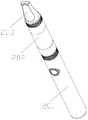
- FIG. 2is a schematic overall structural view of a preferred embodiment of an electronic cigarette according to an embodiment of the present invention
- FIG. 3is a partial cross-sectional structural view of a preferred embodiment of an electronic cigarette according to an embodiment of the present invention.
- FIG. 4is a partial cross-sectional structural view of another preferred embodiment of an electronic cigarette according to an embodiment of the present invention.
- FIG. 5is a schematic cross-sectional structural view showing a partial use state of the electronic cigarette when adding smoke oil according to an embodiment of the present invention
- FIG. 6is a partial cross-sectional structural view of a preferred embodiment of an electronic cigarette according to an embodiment of the present invention.
- FIG. 7is a schematic diagram of a partial exploded connection structure of a preferred embodiment of an electronic cigarette according to an embodiment of the present invention.
- FIG. 8is a partial cross-sectional structural diagram of a preferred embodiment of an electronic cigarette according to an embodiment of the present invention.
- FIG. 2is a schematic structural view of a preferred embodiment of an electronic cigarette according to an embodiment of the present invention
- the electronic cigarette body shown in this embodimentis provided with a battery rod assembly 201;
- the electronic cigarette bodyis further provided with an oil storage assembly 202 for storing smoke oil;
- the oil storage assembly 202is internally provided with an atomizing assembly for atomizing the oil to generate smoke;
- the specific structure of the atomization assemblyis not limited in this embodiment, as long as the atomization assembly can atomize the smoke oil stored in the oil storage assembly 202 according to the electric energy provided by the battery rod assembly 201 to generate smoke. Yes;
- the atomizing componentcan be detachably connected to the oil storage component 202, thereby facilitating the user to replace the atomizing component or the oil storage component 202;
- the oil storage component 202 and the atomizing componentare fixedly connected by a tensioning fit, that is, the oil storage component 202 and the atomizing component are fixedly disposed, thereby effectively improving the electronic component.
- the stability of the structure of the smokeeffectively ensures the sealing of the oil storage assembly 202 and avoids leakage of the oil.
- the specific structure of the battery rod assembly 201is not limited in this embodiment, as long as the atomization assembly can supply power.
- the nozzle assembly 203 coupled to one end of the oil reservoir assembly 202is detachable from the mist atomized by the atomizing assembly by the user through the nozzle assembly 203.
- FIG. 3is a comparison of the electronic cigarette provided by the embodiment of the present invention.
- FIG. 3is a comparison of the electronic cigarette provided by the embodiment of the present invention.
- FIG. 3is a partial cross-sectional structural diagram of the electronic cigarette after the electronic cigarette removes the battery rod assembly 201 and the nozzle assembly 203;
- the oil storage assembly 202is provided with an oil storage chamber 301 for storing the liquid smoke in the oil storage chamber 301, thereby effectively increasing the amount of smoke stored in the electronic cigarette. Effective Increased the length of use of e-cigarettes.
- the oil storage assembly 202is provided with a fuel filler port 302 communicating with the oil reservoir 301 at one end surface;
- the oil storage assembly 202is disposed near the end surface of the nozzle assembly 203 with a fuel filler port 302 communicating with the oil reservoir 301;
- FIG. 4is a partial cross-sectional structural view of another preferred embodiment of the electronic cigarette according to the embodiment of the present invention. Specifically, FIG. 4 is a partial cross-sectional structural diagram of the electronic cigarette after the electronic cigarette is removed from the battery rod assembly 201;
- the atomization assembly 303is inserted into the oil storage assembly 202;
- a limiting portion 304is disposed in the fuel filler 302;
- the specific structure of the sealing member 305is not limited in this embodiment, as long as the sealing member 305 is disposed in the fuel filler opening 302 and abuts against the limiting portion 304, so as to be located in the oil storage.
- the smoke oil in the cavity 301does not leak.
- the sealing member 305has a circular shape matched with the fuel filler opening 302.
- the specific setting manner of the limiting portion 304is not limited. As shown in FIG. 4, that is, the electronic cigarette is in a normal use state, the nozzle assembly 203 is not disposed on the oil storage assembly 202. When the detachment is performed, the surface of the sealing member 305 facing the limiting portion 304 can be resisted by the limiting portion 304;
- the specific structure and arrangement manner of the urging mechanismare not limited in this embodiment, and as long as the state shown in FIG. 4, the urging mechanism can apply the sealing member 305 to the limit. a force in the direction of the bit portion to maintain the state in which the sealing member 305 is in contact with the limiting portion 304;
- the advantage of using the structure shown in this embodimentis that when the electronic cigarette shown in FIG. 4 is in a normal use state, the sealing member 305 is always in accordance with the force of the urging mechanism. When the limiting portion 304 abuts, the sealing member 305 located in the oil filling port 302 can effectively seal the oil storage chamber 301, thereby effectively preventing the leakage of the oil in the oil storage chamber 301 to the suction. At the mouth assembly 203, the user is prevented from pumping to the leaking soot.
- the stability of the structure in which the sealing member 305 is resisted by the limiting portion 304is effectively ensured, and the electronic smog is prevented from being used for a long time.
- the occurrence of loosening between the twocauses the leakage of smoke oil, effectively extending the service life of the electronic cigarette.
- FIG. 5is a schematic structural diagram of a partial use state of the electronic cigarette when adding smoke oil according to an embodiment of the present invention. Specifically, FIG. 5 shows that the electronic cigarette removes the battery. a schematic diagram of a cross-sectional structure of the rod assembly 201 and the oil storage assembly 202 that is adding soot oil to the oil storage assembly 202;
- the nozzle assembly 203is detached from the oil storage assembly 202;
- the nozzle assembly 203 and the oil storage assembly 202are in a detachable connection relationship, for example, by a thread, a buckle, a magnet, or the like.
- the specific detachable connection manneris not limited in this embodiment. .
- This embodimentis preferably described by taking the detachable connection of the nozzle assembly 203 and the oil storage assembly 202 by threads, that is, specifically, when the nozzle assembly 203 is detached, the rotation of the nozzle assembly 203 is performed in a specific direction.
- the nozzle assembly 203is sufficient.
- the force of the sealing member 305 away from the limiting portion 304is given by the oiling tool 501 to move the sealing member 305 away from the limiting portion 304, so that the oiling tool 501 can Adding smoke oil to the oil storage chamber 301;
- the oiling tool 501is used for adding the smoky oil.
- the specific structureis the prior art, and is not described in this embodiment.
- the oiling tool 501abuts the sealing member 305, thereby pressing the sealing member 305 in a direction away from the nozzle assembly 203, thereby causing the sealing member 305 to
- the limiting portion 304is disengaged so that the oil in the oil filling tool 501 can sequentially flow through the gap between the sealing member 305 and the limiting portion 304 and the fueling port 302, and finally flows into the chamber.
- the oil storage chamber 301specifically the direction of the flow of the smoke oil when adding the oil.
- the oiling tool 501can be lifted, so that the oiling tool 501 is separated from the sealing member 305.
- the force of the force mechanismcauses the seal 305 to re-engage with the limiting portion 304, thereby enabling the sealing member 305 to automatically reseal the oil reservoir 301 such that even the nozzle assembly 203 Not connected to the oil storage assembly 202, the smoke oil in the oil reservoir 301 does not leak.
- the structure of the electronic cigarette shown in this embodimentis such that the nozzle assembly 203 is disengaged from the oil storage assembly 202 due to an accidental situation, or the nozzle assembly 203 is screwed by a child.
- the 203is separated from the oil storage assembly 202, and the oil in the oil storage chamber 301 is always resisted by the sealing portion 305, thereby effectively ensuring that the smoke oil is not accidentally
- the leakageimproves the convenience and safety in the process of using the electronic cigarette, and after the completion of adding the oil to the oil storage chamber 301, the sealing member 305 can exert the force at the urging mechanism without the user's operation.
- the lower portionautomatically abuts against the limiting portion 304, so that the oil storage chamber 301 can be resealed, thereby reducing the operation steps of the user and avoiding the occurrence of smoke leakage due to user operation errors or forgetting.
- the specific structure of the urging mechanism shown in this embodimenthas two modes;
- FIG. 6is a partial cross-sectional structural view of a preferred embodiment of the electronic cigarette provided by the embodiment of the present invention; specifically, FIG. 6 is the electronic cigarette removal station.
- FIG. 6is the electronic cigarette removal station.
- the oil storage assembly 202can include a transparent oil storage sleeve 602 to enable the amount of smoke remaining in the oil storage chamber 301 to be viewed through the oil storage jacket 602;
- the oil storage sleeve 602is adjacent to the end of the nozzle assembly 203 is provided with a limit groove 603;
- a fastening sleeve 604is sleeved on the limiting groove 603, and the fastening sleeve 604 is interference-fitted with the limiting groove 603, so that the fastening sleeve 604 can effectively prevent the
- the expansion of the oil storage sleeve 602 in the radial directioneffectively ensures the stability of the electronic cigarette structure and prevents the leakage of the oil in the oil reservoir 301 from leaking to the outer surface of the oil storage assembly 202.
- the fastening sleeve 604is detachable from the end of the oil storage sleeve 602 and the nozzle assembly 203 Unloading
- the inner peripheral wall of the fastening sleeve 604is provided with a threaded section 605 for detachably connecting with the nozzle assembly 203;
- the inner circumferential surface of the fastening sleeve 604is provided with an annular limiting portion 304;
- the sealing member 305is an annular sealing plate, and a peripheral edge of the sealing plate abuts on the limiting portion 304.
- the specific structure of the limiting portion 304 and the sealing member 305is not limited in this embodiment, as long as the sealing member 305 cannot slide out of the oil storage assembly 202 due to the action of the limiting portion 304. Just fine.
- the fastening sleeve 604is the urging mechanism, and the fastening sleeve 604 is a first magnetic member;
- the sealing member 305in the first embodiment, is in the first embodiment. And a magnetic member, and the first magnetic member is magnetically attracted to the second magnetic member to abut the sealing member 305 on the limiting portion 304.
- the tightening sleeve 604 shown in this embodimentis exemplified as the urging mechanism, and is not limited as long as the urging mechanism of the first magnetic member is disposed in the storage.
- the oil component 202can be sucked with the sealing member 305, so that the sealing member 305 is always resisted on the limiting portion 304;
- the sealing member 305may not be disposed as the second magnetic member, but the second magnetic member may be disposed on the sealing member 305, that is, the first The magnetic member may correspond to the position of the second magnetic member.
- the first magnetic member and the second magnetic memberare magnetic material members, and more specifically, the magnetic material member may be iron, cobalt, nickel or an alloy thereof, etc., specifically in this embodiment. There is no limit in the middle.
- the second typeplease refer to FIG. 3 to FIG. 4, that is, the urging mechanism is an elastic member 401;
- one end of the elastic member 401is elastically resisted with the cavity of the atomizing assembly or the oil storage chamber, that is, in this embodiment, as long as one end of the elastic member 401 and the atomizing assembly Or the cavity wall of the oil storage chamber can be elastically resisted, and the specific resisting structure is not limited;
- the other end of the elastic member 401abuts against the sealing member 305, so that when the sealing member 305 moves away from the limiting portion 304, the elastic member 401 is in a compressed state, thereby causing the
- the elastic member 401rebounds, so that the sealing member 305 re-engages the limiting portion 304, thereby sealing the oil storage chamber 301.
- the elastic member 401 shown in this embodimentis a spring
- the elastic member 401may be made of other materials having elastic deformation, and is not limited thereto as long as the elastic force of the sealing member 305 in the direction of the limiting portion 304 can be always applied.
- the third embodimentthe specific structure of the electronic cigarette is described in detail in the embodiment, wherein the embodiment is described by taking the urging mechanism as the elastic member 401 as an example;
- the atomization assemblyis provided with a first vent tube 402 for discharging smoke into the nozzle assembly 203;
- the first vent tube 402is disposed along the axial direction of the electronic cigarette and is inserted into the nozzle assembly 203.
- the sealing member 305 and the elastic member 401are sleeved on the first snorkel. 402;
- the elastic member 401 and the sealing member 305are sequentially sleeved in the direction of the nozzle assembly 203 near the end of the nozzle assembly 203 to make the
- the elastic member 401can elastically reciprocate the sealing member 305 along the guide of the first ventilation pipe 402.
- the elastic member 401 sleeved on the first vent tube 402is abutted between the sealing member 305 and the first vent tube 402 to enable the elastic member 401 to Stabilizing the first vent tube 402 effectively prevents the first vent tube 402 from shaking left and right, thereby effectively ensuring the stability of the smoke concentration conducted to the nozzle assembly 203 via the first vent tube 402, and Avoid leakage of smoke oil.
- the specific structure of the first vent pipe 402is not limited, as long as the mist atomized by the atomizing component can be conducted to the nozzle assembly 203 through the first vent pipe 402. Take The user can be sucked into the smoke through the nozzle assembly 203.
- the atomizing componentis exemplified in the embodiment, and is not limited;
- FIG. 7is a schematic diagram of a partial exploded connection structure of a preferred embodiment of the electronic cigarette according to an embodiment of the present invention
- the atomizing assemblyincludes:
- An outer sleeve 406is disposed at an end of the outer electrode 403 away from the first inner electrode 404;
- the oil storage chamber 301is formed between the atomization sleeve 406 and the oil storage sleeve 602;
- the atomization sleeve 406is inserted with a second ventilation tube 407;
- the second vent pipe 407has a hollow columnar structure, and a vent hole 4071 is opened through the second vent pipe 407 to allow airflow to flow into the second vent pipe 407 through the vent hole 4071, so that the The airflow drives the mist atomized by the atomizing assembly to be conducted to the inside of the nozzle assembly 203 through the first vent pipe 402.
- the atomization sleeve 406is inserted away from the end of the outer electrode 403 with an atomization seat 408;
- An atomization space 409is formed between the atomization seat 408 and the first ventilation tube 402;
- a heating wire assembly 410is erected on the atomization seat 408 such that the heating wire assembly 410 is located inside the atomization space 409, and the atomization space 409 is electrically connected to the first ventilation pipe 402. .
- atomization seat 408is provided with an oil guiding hole 411 which is electrically connected to the oil reservoir 301;
- the heating wire assembly 410includes an oil guiding wire 4101 and a heating wire 4102 wound around the oil guiding wire 4101, and the oil guiding wire 4101 can pass through the oil guiding hole 411 to insert the oil storage chamber In 301, soot oil located in the oil reservoir 301 can be transferred to the 4101 to be atomized by the heating wire 4102 to generate smoke.
- a seal ring 412is disposed between the atomization sleeve 406 and the atomization seat 408 for preventing leakage of the oil in the oil reservoir 301 into the first ventilation tube 402.
- the first end of the heating wire 4102is electrically connected to the outer electrode 403, and the heating wire 4102
- the second endis electrically connected to the first inner electrode 404;
- the followingis a detailed description of how the heating wire 4102 is electrically connected to the outer electrode 403 and the first inner electrode 404;
- the two ends of the heating wire 4102are directly electrically connected to the outer electrode 403 and the first inner electrode 404;
- the atomizing seat 408 and the atomizing sleeve 406are both made of a conductive material, and the atomizing seat 408 and the atomizing sleeve 406 are in contact with each other. ;
- the first end of the heating wire 4102is electrically connected to the outer electrode 403 through the atomizing seat 408 and the atomizing sleeve 406 in sequence;
- the second inner tube 404is inserted into one end of the second vent tube 407, and the second inner electrode 701 is hollow on the other end of the second vent tube 407;
- the airflow in the second vent pipe 407is sequentially circulated to the inside of the atomization space 409 via the second vent pipe 407 and the second inner electrode 701, so that the airflow is located in the atomization space 409.
- the mist atomized by the heating wire assembly 410flows into the interior of the first vent pipe 402, thereby allowing the user to suck through the nozzle assembly 203;
- the second vent tube 407is made of a conductive material such that the second end of the heating wire 4102 sequentially passes through the second inner electrode 701 and the second vent tube 407 and the first inner tube Electrode 404 is electrically connected;
- a second insulating sleeve 702is disposed between the atomizing seat 408 and the second vent tube 407.
- the fourth embodiment of the present inventionprovides a detailed description of the specific structure of the nozzle assembly 203.
- the nozzle assembly 203is elastically connected to the first vent tube 402.
- the nozzle assembly 203is elastically plugged into the first vent tube 402, and the sealing of the oil reservoir 301 is effectively ensured:
- nozzle assembly 203The specific structure of the nozzle assembly 203 is described below with reference to FIG. 4 and FIG. 8. It should be clarified that the description of the nozzle assembly 203 in this embodiment is illustrative and not limited;
- FIG. 8is a partial cross-sectional structural view of a preferred embodiment of an electronic cigarette according to an embodiment of the present invention. Specifically, FIG. 8 is a schematic cross-sectional structural view of the nozzle assembly 203;
- the nozzle assembly 203includes:
- one end of the connecting sleeve 801is detachably connected to the oil storage assembly 202;
- the outer peripheral wall of the connecting sleeve 801may be provided with a threaded section 804 for detachable connection with the oil storage assembly 202;
- the other end of the connecting sleeve 801is detachably connected to the suction nozzle 802;
- the connecting sleeve 801is provided with an internal thread 805 at a position corresponding to the nozzle 802, and an external thread 806 is disposed at a position corresponding to the internal thread 805 of the nozzle 802;
- An annular locking plate 807is disposed on an inner circumferential surface of the connecting sleeve 801 away from the suction nozzle 802.
- the elastic sealing ring 803is sleeved on the first ventilation pipe 402 and is engaged with the clamping platform. On 807.
- the first vent tube 402is clamped by the card 807, thereby further preventing the first snorkel 402 from shaking inside the electronic cigarette, thereby effectively improving the stability of the electronic cigarette structure and avoiding smoke oil.
- the leak
- the blocking step 703is disposed at an end of the first vent pipe 402 away from the limiting portion 304 , and the end of the elastic member 401 away from the sealing member 305 is resisted at The barrier step 703 is on.
- the blocking step 703may be integrally formed for the first vent tube 402, or the blocking step 703 may be a separate component that can be assembled and fixedly disposed on the first snorkel 402. The above is not limited in this embodiment.
- a condensed soot storage space 808 for storing condensed sootis formed between the end surface of the nozzle 802 and the card 807;
- the condensed smogcan be condensed in the condensed smoky oil storage space 808 to prevent the user from absorbing, thereby effectively Improves the health and taste of the user during the pumping process.
- the nozzle 802is provided with an air outlet 809 communicating with the condensed soot storage space 808.
- the smoke discharged from the first snorkel 402passes through the condensed smoky oil storage space 808, and then is discharged from the vent 809, so that the user can suck the smoke through the vent 809.
Landscapes
- Health & Medical Sciences (AREA)
- Child & Adolescent Psychology (AREA)
- General Health & Medical Sciences (AREA)
- Coating Apparatus (AREA)
- Disinfection, Sterilisation Or Deodorisation Of Air (AREA)
Abstract
Description
Translated fromChinese本实用新型涉及电子烟技术领域,尤其涉及的是一种能够有效的防止烟油泄漏的电子烟。The utility model relates to the technical field of electronic cigarettes, in particular to an electronic cigarette capable of effectively preventing leakage of smoke oil.
现有技术中的电子烟的具体结构可参见图1所示,现有技术中的电子烟包括雾化组件101和电池杆组件102,所述雾化组件101具体包括雾化套103,所述雾化套103内部设置有用于存储烟油的储油腔104,用于雾化该储油腔104内部烟油的电热丝105,以及用于抽吸烟雾的吸嘴106,现有技术中,所述吸嘴106与所述雾化套103之间为螺纹连接,只要通过旋拧所述吸嘴106,即可将所述吸嘴106从所述雾化套103上拆卸下来;The specific structure of the electronic cigarette in the prior art can be seen in FIG. 1. The electronic cigarette in the prior art includes an
可见采用现有技术中所述的雾化组件101的结构,极容易将所述吸嘴106从所述雾化套103上拆卸下来,若被儿童接触,则极容易使得儿童旋拧所述吸嘴106,从而使得儿童能够接触到雾化套103内部所存储的烟油,若儿童喝到烟油,则会发生极严重的后果;而且雾化组件101在长时间使用后,即容易使得所述吸嘴106与所述雾化套103之间的螺纹连接相互松脱,若吸嘴106意外脱落,则雾化套103内部的烟油会发生泄漏,为用户带来极大的不便。It can be seen that the structure of the atomizing
实用新型内容Utility model content
本实用新型提供了一种能够有效的防止烟油泄漏的电子烟;The utility model provides an electronic cigarette capable of effectively preventing leakage of smoke oil;
一种电子烟,其中,包括:An electronic cigarette, including:
电子烟本体;Electronic cigarette body;
所述电子烟本体设置有用于存储烟油的储油组件、用于雾化所述烟油的雾化组件及可拆卸连接于所述储油组件一端的吸嘴组件,所述储油组件设置有储油腔,所述储油组件的一端端面处设置有与所述储油腔相连通的加油口,所述吸嘴组件盖设在所述加油口上,所述雾化组件插设于所述储油组件内;The electronic cigarette body is provided with an oil storage assembly for storing smoke oil, an atomization assembly for atomizing the smoke oil, and a nozzle assembly detachably connected to one end of the oil storage assembly, the oil storage assembly is configured An oil storage chamber is provided, and an oil supply port communicating with the oil storage chamber is disposed at one end surface of the oil storage assembly, the nozzle assembly is disposed on the fuel filler port, and the atomization assembly is inserted in the Said in the oil storage assembly;
所述加油口内设置有限位部、盖设在所述加油口内的密封件及用于给所述密封件施加朝所述限位部方向的力的施力机构,所述密封件面向所述限位部的表面与所述限位部相抵持,以使需要添加烟油时,在拆卸所述吸嘴组件后通过用于向所述储油腔内添加烟油的注油工具给所述密封件远离所述限位部方向的力,以使所述密封件与所述限位部相脱离,以使所述注油工具能够向所述储油腔内添加烟油,当所述注油工具与所述密封件相脱离时,所述密封件受到所述施力机构的力而与所述限位部相抵持以密封所述储油腔。a sealing portion disposed in the fueling port, a sealing member disposed in the fueling opening, and a biasing mechanism for applying a force in the direction of the limiting portion to the sealing member, the sealing member facing the limit PositionalThe surface is abutted against the limiting portion, so that when the smoke oil needs to be added, the sealing member is separated from the sealing member by an oiling tool for adding the oil to the oil storage chamber after the nozzle assembly is disassembled a force in the direction of the limiting portion to disengage the sealing member from the limiting portion to enable the oiling tool to add smoke oil to the oil reservoir, when the oiling tool and the sealing member When the phase is disengaged, the sealing member is pressed against the limiting portion by the force of the urging mechanism to seal the oil reservoir.
优选的,所述施力机构为设置在所述储油组件上的第一磁性件;Preferably, the urging mechanism is a first magnetic member disposed on the oil storage assembly;
所述密封件为第二磁性件,或,在所述密封件上与所述第一磁性件对应位置设置有第二磁性件;The sealing member is a second magnetic member, or a second magnetic member is disposed on the sealing member at a position corresponding to the first magnetic member;
其中,所述第一磁性件与所述第二磁性件磁性相吸,以使所述密封件抵持在所述限位部上。Wherein the first magnetic member and the second magnetic member are magnetically attracted to cause the sealing member to abut against the limiting portion.
优选的,所述第一磁性件以及所述第二磁性件为磁性材料制件。Preferably, the first magnetic member and the second magnetic member are made of a magnetic material.
优选的,所述储油组件与所述雾化组件通过涨紧配合固定连接。Preferably, the oil storage component and the atomization component are fixedly connected by a tension fit.
优选的,所述施力机构为弹性件,所述弹性件的一端与所述雾化组件或所述储油腔的腔壁弹性抵持,所述弹性件的另一端抵持在所述密封件上,以使所述密封件沿远离所述限位部方向运动时,所述弹性件呈压缩状态。Preferably, the urging mechanism is an elastic member, one end of the elastic member elastically abuts against a cavity wall of the atomization assembly or the oil reservoir, and the other end of the elastic member abuts against the seal The elastic member is in a compressed state when the sealing member moves in a direction away from the limiting portion.
优选的,所述雾化组件设置有用于将烟雾排出至所述吸嘴组件内的第一通气管,所述第一通气管沿所述电子烟的轴向延伸设置并插设在所述吸嘴组件内,所述密封件及所述弹性件均套设在所述第一通气管上,以使所述弹性件能够带动所述密封件沿所述第一通气管的导向弹性往复运动。Preferably, the atomizing assembly is provided with a first vent pipe for discharging smoke into the nozzle assembly, and the first vent pipe is disposed along an axial extension of the electronic cigarette and inserted in the suction In the nozzle assembly, the sealing member and the elastic member are sleeved on the first ventilation tube, so that the elastic member can elastically reciprocate the sealing member along the guiding of the first ventilation tube.
优选的,位于所述第一通气管远离所述限位部的一端设置有阻挡台阶,所述弹性件远离所述密封件的一端抵持在所述阻挡台阶上。Preferably, a blocking step is disposed at an end of the first vent pipe away from the limiting portion, and an end of the elastic member away from the sealing member abuts on the blocking step.
优选的,所述吸嘴组件与所述第一通气管弹性插接相连。Preferably, the nozzle assembly is elastically coupled to the first vent tube.
优选的,所述储油组件包括透明的储油套及套设在所述储油套一端的紧固套,所述紧固套远离所述储油套的一端与所述吸嘴组件进行可拆卸连接,所述紧固套的内周面设置有环形的所述限位部,所述密封件为环形的密封板,所述密封板的周缘抵持在所述限位部上。Preferably, the oil storage assembly includes a transparent oil storage sleeve and a fastening sleeve sleeved at one end of the oil storage sleeve, and the fastening sleeve is away from an end of the oil storage sleeve and the nozzle assembly. The inner circumferential surface of the fastening sleeve is provided with an annular limiting portion, and the sealing member is an annular sealing plate, and a peripheral edge of the sealing plate abuts against the limiting portion.
优选的,所述吸嘴组件包括连接套、吸嘴及弹性密封环,所述连接套的一端与所述储油组件可拆卸连接,所述连接套的另一端与所述吸嘴可拆卸连接,所述连接套远离所述吸嘴的一端内周面上设置有环形的卡台,所述弹性密封环套设在所述第一通气管上并卡接在所述卡台上。Preferably, the nozzle assembly comprises a connecting sleeve, a nozzle and an elastic sealing ring, one end of the connecting sleeve is detachably connected to the oil storage assembly, and the other end of the connecting sleeve is detachably connected to the nozzle An annular card seat is disposed on an inner circumferential surface of the connecting sleeve away from the end of the nozzle, and the elastic sealing ringNested on the first vent pipe and snapped onto the card table.
优选的,所述吸嘴的一端插设在所述连接套内,所述吸嘴的端面与所述卡台之间形成有用于存储冷凝烟油的冷凝烟油存储空间,所述吸嘴设置有与所述冷凝烟油存储空间相连通的出气孔,用户吸烟时所述第一通气管排出的烟雾先经所述冷凝烟油存储空间后,再从所述出气孔中排出。Preferably, one end of the nozzle is inserted into the connecting sleeve, and a condensed soot storage space for storing condensed smoke oil is formed between the end surface of the nozzle and the card table, and the nozzle is set. There is an air outlet communicating with the condensed tobacco oil storage space, and the smoke discharged by the first vent pipe passes through the condensed smoke oil storage space before being smoked by the user, and then discharged from the air outlet hole.
优选的,所述雾化组件包括外电极、插设在所述外电极内的第一内电极及设置在所述外电极和所述第一内电极之间的第一绝缘套;Preferably, the atomization assembly includes an outer electrode, a first inner electrode interposed in the outer electrode, and a first insulating sleeve disposed between the outer electrode and the first inner electrode;
所述外电极远离所述第一内电极的一端插设有雾化套,所述雾化套和储油套之间形成有所述储油腔,其中,所述储油组件设置有所述储油套;An atomizing sleeve is inserted into an end of the outer electrode away from the first inner electrode, and the oil storage chamber is formed between the atomizing sleeve and the oil storage sleeve, wherein the oil storage component is provided with the Oil storage jacket
所述雾化套内插设有第二通气管,且所述雾化套远离所述外电极的端部插设有雾化座,所述雾化座和所述第一通气管之间形成有雾化空间;a second vent tube is inserted into the atomization sleeve, and an atomization seat is inserted into the end of the atomization sleeve away from the outer electrode, and the atomization seat and the first vent tube are formed. There is atomization space;
所述雾化座上架设固定有电热丝组件,以使所述电热丝组件位于所述雾化空间内部,贯穿所述雾化座设置有与所述储油腔导通的导油孔;An electric heating wire assembly is erected on the atomizing seat, so that the electric heating wire assembly is located inside the atomizing space, and an oil guiding hole that is electrically connected to the oil storage cavity is disposed through the atomizing seat;
所述电热丝组件包括导油绳和缠绕设置在所述导油绳上的电热丝,且所述导油绳能够穿过所述导油孔以插入所述储油腔内,所述电热丝的第一端与所述外电极电连接,所述电热丝的第二端与所述第一内电极电连接;The electric heating wire assembly includes an oil guiding rope and a heating wire wound around the oil guiding rope, and the oil guiding rope can pass through the oil guiding hole to be inserted into the oil storage chamber, the heating wire The first end is electrically connected to the outer electrode, and the second end of the heating wire is electrically connected to the first inner electrode;
所述雾化套和所述雾化座之间设置有密封圈,所述密封圈用于防止所述储油腔内的烟油泄漏至所述第一通气管内。A sealing ring is disposed between the atomizing sleeve and the atomizing seat, and the sealing ring is configured to prevent smoke oil in the oil storage chamber from leaking into the first ventilation pipe.
优选的,Preferably,
所述雾化座和所述雾化套均由导电材质制成,以使所述电热丝的第一端依次通过所述雾化座和所述雾化套与所述外电极电连接;The atomizing seat and the atomizing sleeve are both made of a conductive material, so that the first end of the heating wire is electrically connected to the outer electrode through the atomizing seat and the atomizing sleeve in sequence;
所述第二通气管一端插设有所述第一内电极,所述第二通气管的另一端套设有呈中空状的第二内电极,以使所述第二通气管内的气流依次经由所述第二通气管和所述第二内电极流通至所述雾化空间内部;One end of the second vent tube is inserted with the first inner electrode, and the other end of the second vent tube is sleeved with a second inner electrode that is hollow, so that the airflow in the second vent tube is sequentially passed through The second vent pipe and the second inner electrode circulate to the inside of the atomization space;
所述第二通气管由导电材质制成,以使所述电热丝的第二端依次通过所述第二内电极和所述第二通气管与所述第一内电极电连接;The second vent tube is made of a conductive material such that the second end of the heating wire is electrically connected to the first inner electrode through the second inner electrode and the second vent tube in sequence;
所述雾化座和所述第二通气管之间设置有第二绝缘套。A second insulating sleeve is disposed between the atomizing seat and the second vent pipe.
本实用新型所提供的电子烟包括电子烟本体,所述电子烟本体设置有用于存储烟油的储油组件、用于雾化所述烟油的雾化组件及可拆卸连接于所述储油组件一端的吸嘴组件,所述储油组件设置有储油腔,所述储油组件的一端端面处设置有与所述储油腔相连通的加油口,所述吸嘴组件盖设在所述加油口上,所述雾化组件插设于所述储油组件内;所述加油口内设置有限位部、盖设在所述加油口内的密封件及用于给所述密封件施加朝所述限位部方向的力的施力机构,所述密封件面向所述限位部的表面与所述限位部相抵持。采用本实用新型所提供的电子烟的优势在于,使得即便吸嘴组件因意外情况与所述储油组件相脱离,或因儿童旋拧所述吸嘴组件使得所述吸嘴组件与所述储油组件相脱离,位于所述储油腔内的烟油,因所述密封件始终与所述限位部相抵持,进而有效的保障了烟油不会意外泄漏,提升了使用电子烟过程中的便利和安全,而且在往所述储油腔内添加烟油完成后,所述密封件无需用户的操作即可在所述施力机构的作用力下自动与所述限位部相抵持,从而可重新密封所述储油腔,减少了用户的操作步骤,避免因用户操作失误或遗忘而发生烟油泄漏的情况。The electronic cigarette provided by the present invention includes an electronic cigarette body, the electronic cigarette body is provided with an oil storage assembly for storing the tobacco oil, an atomizing assembly for atomizing the smoke oil, and detachably connected to the oil storage body.a nozzle assembly at one end of the assembly, the oil storage assembly is provided with an oil storage chamber, and an oil supply port communicating with the oil storage chamber is disposed at one end surface of the oil storage assembly, and the nozzle assembly is disposed at the end of the oil storage assembly On the fuel filler port, the atomization assembly is inserted into the oil storage assembly; a sealing portion is disposed in the fueling port, a sealing member is disposed in the fueling opening, and the sealing member is applied to the sealing member a force applying mechanism of the force in the direction of the limiting portion, wherein the surface of the sealing member facing the limiting portion abuts against the limiting portion. The advantage of using the electronic cigarette provided by the present invention is that the nozzle assembly and the reservoir are caused even if the nozzle assembly is disengaged from the oil storage assembly due to an accidental situation, or the nozzle assembly is screwed by a child. The oil component is disengaged, and the oil in the oil storage chamber is always in contact with the limiting portion because the sealing member is always in contact with the limiting portion, thereby effectively ensuring that the smoke oil does not accidentally leak, thereby improving the process of using the electronic cigarette. Convenience and safety, and after the completion of adding the oil to the oil storage chamber, the sealing member can automatically resist the limiting portion under the force of the urging mechanism without the user's operation. Thereby, the oil storage chamber can be resealed, the operation steps of the user are reduced, and the leakage of the smoke oil due to the user's operation error or forgetting is avoided.
图1为现有技术中的电子烟的剖面结构示意图;1 is a schematic cross-sectional structural view of an electronic cigarette in the prior art;
图2为本实用新型实施例所提供的电子烟的一种较佳实施例整体结构示意图;2 is a schematic overall structural view of a preferred embodiment of an electronic cigarette according to an embodiment of the present invention;
图3为本实用新型实施例所提供的电子烟的一种较佳实施例局部剖面结构示意图;3 is a partial cross-sectional structural view of a preferred embodiment of an electronic cigarette according to an embodiment of the present invention;
图4为本实用新型实施例所提供的电子烟的另一种较佳实施例局部剖面结构示意图;4 is a partial cross-sectional structural view of another preferred embodiment of an electronic cigarette according to an embodiment of the present invention;
图5为本实用新型实施例所提供的添加烟油时的所述电子烟的局部使用状态剖面结构示意图;5 is a schematic cross-sectional structural view showing a partial use state of the electronic cigarette when adding smoke oil according to an embodiment of the present invention;
图6为本实用新型实施例所提供的电子烟的一种较佳实施例局部剖面结构示意图;6 is a partial cross-sectional structural view of a preferred embodiment of an electronic cigarette according to an embodiment of the present invention;
图7为本实用新型实施例所提供的电子烟的一种较佳实施例局部爆炸连接结构示意图;FIG. 7 is a schematic diagram of a partial exploded connection structure of a preferred embodiment of an electronic cigarette according to an embodiment of the present invention; FIG.
图8为本实用新型实施例所提供的电子烟的一种较佳实施例局部剖面结构示意图。FIG. 8 is a partial cross-sectional structural diagram of a preferred embodiment of an electronic cigarette according to an embodiment of the present invention.
实施例一,本实施例对能够有效的防止烟油泄漏,可避免意外吸食到烟油的电子烟的具体结构进行详细说明:In the first embodiment, the specific structure of the electronic cigarette capable of effectively preventing the leakage of the smoke oil and avoiding accidental smoking to the smoke oil is described in detail:
首先请参见图2所示,其中,图2为本实用新型实施例所提供的电子烟的一种较佳实施例整体结构示意图;Referring to FIG. 2, FIG. 2 is a schematic structural view of a preferred embodiment of an electronic cigarette according to an embodiment of the present invention;
如图2所示,本实施例所示的电子烟本体设置有电池杆组件201;As shown in Figure 2, the electronic cigarette body shown in this embodiment is provided with a
所述电子烟本体还设置有用于存储烟油的储油组件202;The electronic cigarette body is further provided with an
所述储油组件202内部设置有用于雾化烟油以生成烟雾的雾化组件;The
本实施例对所述雾化组件的具体结构不做限定,只要所述雾化组件能够根据所述电池杆组件201所提供的电能雾化所述储油组件202所存储的烟油以生成烟雾即可;The specific structure of the atomization assembly is not limited in this embodiment, as long as the atomization assembly can atomize the smoke oil stored in the
具体的,在一种实施方式中,所述雾化组件可与所述储油组件202之间可拆卸连接,进而便于用户更换雾化组件或储油组件202;Specifically, in an embodiment, the atomizing component can be detachably connected to the
在另一种实施方式中,所述储油组件202与所述雾化组件通过涨紧配合固定连接,即所述储油组件202与所述雾化组件为固定设置,从而有效的提升了电子烟结构的稳定性,有效的保障了所述储油组件202的密封性,避免烟油的泄漏。In another embodiment, the
本实施例对所述电池杆组件201的具体结构不做限定,只要能够为所述雾化组件供电即可。The specific structure of the
可拆卸连接于所述储油组件202一端的吸嘴组件203,即用户通过所述吸嘴组件203能够抽吸到所述雾化组件所雾化的烟雾。The
以下对设置有所述雾化组件的所述储油组件202的内部结构进行详细说明,首先请参见图3所示,其中,图3为本实用新型实施例所提供的电子烟的一种较佳实施例局部剖面结构示意图;The internal structure of the
具体的,即图3为所述电子烟去掉所述电池杆组件201和所述吸嘴组件203后的电子烟的局部剖面结构示意图;Specifically, FIG. 3 is a partial cross-sectional structural diagram of the electronic cigarette after the electronic cigarette removes the
由图3所示可知,所述储油组件202设置有储油腔301,以在所述储油腔301中存储呈液态的烟油,从而有效的提升了电子烟所存储的烟油量,有效的提升了电子烟的使用时长。As shown in FIG. 3, the
所述储油组件202的一端端面处设置有与所述储油腔301相连通的加油口302;The
具体的,由图3所示,所述储油组件202靠近所述吸嘴组件203的端面处设置有与所述储油腔301相连通的加油口302;Specifically, as shown in FIG. 3, the
所述吸嘴组件203盖设在所述加油口302上,可参见图4所示,其中,图4为本实用新型实施例所提供的电子烟的另一种较佳实施例局部剖面结构示意图,具体的,即图4为所述电子烟去掉所述电池杆组件201后的电子烟的局部剖面结构示意图;The
结合图3和图4所示,所述雾化组件303插设于所述储油组件202内;As shown in FIG. 3 and FIG. 4, the
所述加油口302内设置有限位部304;a limiting
盖设在所述加油口302内的密封件305;a
本实施例对所述密封件305的具体结构不做限定,只要所述密封件305盖设在所述加油口302内,且与所述限位部304相抵持时,使得位于所述储油腔301内的烟油不会泄漏即可。The specific structure of the sealing
较佳的,所述密封件305呈与所述加油口302匹配设置的圆环形。Preferably, the sealing
及用于给所述密封件305施加朝所述限位部方向的力的施力机构;And an urging mechanism for applying a force to the
本实施例中,对所述限位部304具体设置方式不做限定,只要如图4所示时,即电子烟在正常使用状态,所述吸嘴组件203未从所述储油组件202上拆卸下来时,所述密封件305面向所述限位部304的表面与所述限位部304相抵持即可;In this embodiment, the specific setting manner of the limiting
更具体的,本实施例对所述施力机构的具体结构和设置方式不做限定,只要如图4所示的状态时,所述施力机构能够给所述密封件305施加朝所述限位部方向的力,以使保持所述密封件305与所述限位部304相抵持的状态;More specifically, the specific structure and arrangement manner of the urging mechanism are not limited in this embodiment, and as long as the state shown in FIG. 4, the urging mechanism can apply the sealing
可见,采用本实施例所示的结构的优势在于,因如图4所示的电子烟处于正常的使用状态时,因所述施力机构的作用力,使得所述密封件305始终与所述限位部304相抵持,则位于所述加油口302内的密封件305能够有效的密封所述储油腔301,从而有效的避免位于所述储油腔301内的烟油泄漏至所述吸嘴组件203处,避免用户抽吸到泄漏的烟油。It can be seen that the advantage of using the structure shown in this embodiment is that when the electronic cigarette shown in FIG. 4 is in a normal use state, the sealing
而且,因所述施力机构的作用力,从而有效的保障了所述密封件305与所述限位部304相抵持的结构的稳定性,避免了电子烟因长时间使用而使得各器件之间发生松脱进而使得烟油泄漏情况的发生,有效的延长了电子烟的使用寿命。Moreover, due to the force of the urging mechanism, the stability of the structure in which the sealing
以下对采用本实施例所示的电子烟时,是如何实现往所述储油腔301内添加烟油的进行详细说明;The following is a detailed description of how to add the smoke oil to the
请参见图5所示,图5为本实用新型实施例所提供的添加烟油时的所述电子烟的局部使用状态结构示意图,具体的,图5所示为所述电子烟去掉所述电池杆组件201,且正在往所述储油组件202内添加烟油的所述储油组件202的剖面结构示意图;Referring to FIG. 5 , FIG. 5 is a schematic structural diagram of a partial use state of the electronic cigarette when adding smoke oil according to an embodiment of the present invention. Specifically, FIG. 5 shows that the electronic cigarette removes the battery. a schematic diagram of a cross-sectional structure of the
在添加烟油时的具体步骤为:The specific steps when adding smoke oil are:
1、将所述吸嘴组件203从所述储油组件202上拆卸下来;1. The
本实施例中,所述吸嘴组件203与所述储油组件202为可拆卸的连接关系,例如通过螺纹,卡扣,磁铁等任意方式,具体可拆卸连接方式在本实施例中不做限定。In this embodiment, the
本实施例较佳的以所述吸嘴组件203和所述储油组件202通过螺纹进行可拆卸连接为例进行说明,即具体在拆卸所述吸嘴组件203时,只要沿特定方向旋转所述吸嘴组件203即可。This embodiment is preferably described by taking the detachable connection of the
2、通过注油工具501给所述密封件305远离所述限位部304方向的力,以使所述密封件305沿远离所述限位部304方向运动,以使所述注油工具501能够向所述储油腔301内添加烟油;2. The force of the sealing
其中,所述注油工具501用于添加烟油,具体结构为现有技术,在本实施例中不做赘述。The
具体的,在添加烟油的过程中,所述注油工具501抵持所述密封件305,从而沿远离所述吸嘴组件203的方向压所述密封件305,进而使得所述密封件305与所述限位部304相脱离,以使所述注油工具501内的烟油能够依次流经所述密封件305与所述限位部304之间的间隙以及所述加油口302,最后流入所述储油腔301,具体的添加烟油时的烟油流动方向课参见图5所示的箭头方向。Specifically, in the process of adding the oil, the
本实施例中,在往所述储油腔301内添加烟油完成后,可提起所述注油工具501,从而使得所述注油工具501与所述密封件305相脱离,此时因所述施力机构的作用力,使得所述密封件305重新与所述限位部304相抵持,进而使得所述密封件305能够自动重新密封所述储油腔301,使得即便所述吸嘴组件203还未连接至所述储油组件202上,所述储油腔301内的烟油也不会发生泄漏。In this embodiment, after the oil is added to the
可见,采用本实施例所示的电子烟的结构,使得即便吸嘴组件203因意外情况与所述储油组件202相脱离,或因儿童旋拧所述吸嘴组件203使得所述吸嘴组件203与所述储油组件202相脱离,位于所述储油腔301内的烟油,因所述密封件305始终与所述限位部304相抵持,进而有效的保障了烟油不会意外泄漏,提升了使用电子烟过程中的便利和安全,而且在往所述储油腔301内添加烟油完成后,所述密封件305无需用户的操作即可在所述施力机构的作用力下自动与所述限位部304相抵持,从而可重新密封所述储油腔301,减少了用户的操作步骤,避免因用户操作失误或遗忘而发生烟油泄漏的情况。It can be seen that the structure of the electronic cigarette shown in this embodiment is such that the
实施例二,本实施例对所述施力机构的具体设置方式进行详细说明,需明确的是,本实施例对所述施力机构的描述为举例说明,不做限定;The second embodiment, the specific setting manner of the urging mechanism is described in detail in the embodiment. It should be clarified that the description of the urging mechanism in this embodiment is exemplified and not limited;
本实施例所示的所述施力机构的具体结构有两种方式;The specific structure of the urging mechanism shown in this embodiment has two modes;
第一种:请参见图6所示,其中,图6为本实用新型实施例所提供的电子烟的一种较佳实施例局部剖面结构示意图;具体的,图6为所述电子烟去掉所述电池杆组件201和所述吸嘴组件203后的电子烟的局部剖面结构示意图;The first type is shown in FIG. 6 , wherein FIG. 6 is a partial cross-sectional structural view of a preferred embodiment of the electronic cigarette provided by the embodiment of the present invention; specifically, FIG. 6 is the electronic cigarette removal station. A partial cross-sectional structural view of the electronic cigarette after the
首先对所述储油组件202靠近所述吸嘴组件203端部的结构进行说明:First, the structure of the
所述储油组件202可包括有透明的储油套602,以使通过所述储油套602能够查看所述储油腔301内剩余的烟油量;The
所述储油套602靠近所述吸嘴组件203的端部设置有限位凹槽603;The
在所述限位凹槽603上套设有紧固套604,所述紧固套604与所述限位凹槽603之间过盈配合,以使所述紧固套604能够有效的防止所述储油套602沿径向方向膨胀,有效的保障了电子烟结构的稳定性,以及避免储油腔301内的烟油泄漏至所述储油组件202的外表面。A
所述紧固套604远离所述储油套602的一端与所述吸嘴组件203进行可拆卸连接;The
具体的,在所述紧固套604内周壁设置有用于与所述吸嘴组件203可拆卸连接的螺纹段605;Specifically, the inner peripheral wall of the
具体的,如何通过所述螺纹段605实现所述紧固套604和所述吸嘴组件203之间的可拆卸连接的为现有技术,在本实施例中不做赘述。Specifically, it is a prior art to implement the detachable connection between the
所述紧固套604的内周面设置有环形的所述限位部304;The inner circumferential surface of the
所述密封件305为环形的密封板,所述密封板的周缘抵持在所述限位部304上。The sealing
本实施例对所述限位部304和所述密封件305的具体结构不做限定,只要因所述限位部304的作用使得所述密封件305无法从所述储油组件202内滑动出去即可。The specific structure of the limiting
具体的,如图6所示,所述紧固套604即为所述施力机构,且所述紧固套604为第一磁性件;Specifically, as shown in FIG. 6, the
本实施例中,为使得所述第一磁性件能够给始终所述密封件305远离所述限位部304方向的力,则较佳的,本实施例中,所述密封件305本体为第二磁性件,且所述第一磁性件与所述第二磁性件磁性相吸,以使所述密封件305抵持在所述限位部304上。In this embodiment, in order to enable the first magnetic member to always apply a force in the direction of the sealing
需明确的是,本实施例所示的所述紧固套604为所述施力机构为举例说明,不做限定,只要为所述第一磁性件的所述施力机构设置在所述储油组件202上,且能够与所述密封件305相吸即可,从而使得所述密封件305始终抵持在所述限位部304上;It should be clarified that the tightening
还需明确的是,本实施例中,所述密封件305也可不设置成所述第二磁性件,而是将所述第二磁性件设置在所述密封件305上,即所述第一磁性件与所述第二磁性件位置对应即可。It should be further noted that, in this embodiment, the sealing
即只要相互吸引的所述第一磁性件与所述第二磁性件能够使得所述密封件305始终抵持在所述限位部304上即可。That is, as long as the first magnetic member and the second magnetic member that are attracted to each other can cause the sealing
具体的,上述所述第一磁性件以及所述第二磁性件为磁性材料制件,更具体的,所述磁性材料制件可为铁、钴、镍或其合金等,具体在本实施例中不做限定。Specifically, the first magnetic member and the second magnetic member are magnetic material members, and more specifically, the magnetic material member may be iron, cobalt, nickel or an alloy thereof, etc., specifically in this embodiment. There is no limit in the middle.
第二种:请参见图3至图4所示,即所述施力机构为弹性件401;The second type: please refer to FIG. 3 to FIG. 4, that is, the urging mechanism is an
具体的,所述弹性件401的一端与所述雾化组件或所述储油腔的腔壁弹性抵持,即在本实施例中,只要所述弹性件401的一端与所述雾化组件或所述储油腔的腔壁弹性抵持即可,对具体抵持的结构不做限定;Specifically, one end of the
所述弹性件401的另一端抵持在所述密封件305上,以使所述密封件305沿远离所述限位部304方向运动时,所述弹性件401呈压缩状态,进而使得所述密封件305不受外力的作用下,所述弹性件401回弹,使得所述密封件305重新抵持所述限位部304,进而密封所述储油腔301。The other end of the
具体的,本实施例所示的所述弹性件401为弹簧;Specifically, the
当然,所述弹性件401还可为具有弹性形变的其他材质制成,具体不做限定,只要能够始终给所述密封件305朝向所述限位部304方向的弹力即可。Of course, the
实施例三,本实施例对所述电子烟的具体结构进行详细说明,其中,本实施例以所述施力机构为弹性件401为例进行说明;The third embodiment, the specific structure of the electronic cigarette is described in detail in the embodiment, wherein the embodiment is described by taking the urging mechanism as the
首先,请参见图3所示,所述雾化组件设置有用于将烟雾排出至所述吸嘴组件203内的第一通气管402;First, as shown in Figure 3, the atomization assembly is provided with a
所述第一通气管402沿所述电子烟的轴向延伸设置并插设在所述吸嘴组件203内,所述密封件305及所述弹性件401均套设在所述第一通气管402上;The
具体的,所述第一通气管402靠近所述吸嘴组件203的端部沿靠近所述吸嘴组件203的方向依次套设有所述弹性件401和所述密封件305,以使所述弹性件401能够带动所述密封件305沿所述第一通气管402的导向弹性往复运动。Specifically, the
较佳的是,因套设在所述第一通气管402上的所述弹性件401抵持在所述密封件305和所述第一通气管402之间,以使所述弹性件401能够稳固所述第一通气管402,有效的防止所述第一通气管402左右晃动,从而有效的保障了经由所述第一通气管402传导至所述吸嘴组件203内烟雾浓度的稳定,而且避免烟油的泄漏。Preferably, the
本实施例中,对所述第一通气管402的具体结构不做限定,只要所述雾化组件所雾化的烟雾能够通过所述第一通气管402导通至所述吸嘴组件203,以使用户通过所述吸嘴组件203能够抽吸到烟雾即可。In this embodiment, the specific structure of the
以下对所述雾化组件的具体结构进行详细说明,需明确的是,本实施例对所述雾化组件为举例说明,不做限定;The specific structure of the atomizing component is described in detail below. It should be clarified that the atomizing component is exemplified in the embodiment, and is not limited;
请参见图4和图7所示,其中,图7为本实用新型实施例所提供的电子烟的一种较佳实施例局部爆炸连接结构示意图;Referring to FIG. 4 and FIG. 7 , FIG. 7 is a schematic diagram of a partial exploded connection structure of a preferred embodiment of the electronic cigarette according to an embodiment of the present invention;
所述雾化组件包括:The atomizing assembly includes:
外电极403;
插设在所述外电极403内的第一内电极404;a first
及设置在所述外电极403和所述第一内电极404之间的第一绝缘套405;And a first
所述外电极403远离所述第一内电极404的一端套设有雾化套406;An
其中,所述雾化套406和所述储油套602之间形成有所述储油腔301;Wherein, the
所述雾化套406内插设有第二通气管407;The
所述第二通气管407呈中空的柱状结构,且贯穿所述第二通气管407开设有通气孔4071,以使气流通过所述通气孔4071流入所述第二通气管407内部,以使该气流带动所述雾化组件所雾化的烟雾通过所述第一通气管402导通至所述吸嘴组件203内部。The
所述雾化套406远离所述外电极403的端部插设有雾化座408;The
所述雾化座408和所述第一通气管402之间形成有雾化空间409;An
所述雾化座408上架设固定有电热丝组件410,以使所述电热丝组件410位于所述雾化空间409内部,且所述雾化空间409与所述第一通气管402导通设置。A
贯穿所述雾化座408设置有与所述储油腔301导通的导油孔411;Through the
所述电热丝组件410包括导油绳4101和缠绕设置在所述导油绳4101上的电热丝4102,且所述导油绳4101能够穿过所述导油孔411以插入所述储油腔301内,以使位于所述储油腔301内的烟油能够传送至所述4101上以被所述电热丝4102所雾化以生成烟雾。The
所述雾化套406和所述雾化座408之间设置有密封圈412,所述密封圈412用于防止所述储油腔301内的烟油泄漏至所述第一通气管402内。A
所述电热丝4102的第一端与所述外电极403电连接,所述电热丝4102的第二端与所述第一内电极404电连接;The first end of the heating wire 4102 is electrically connected to the
以下对所述电热丝4102如何与所述外电极403和所述第一内电极404进行电连接的进行详细说明;The following is a detailed description of how the heating wire 4102 is electrically connected to the
本实施例中,提供了两种电连接方式:In this embodiment, two types of electrical connections are provided:
第一种,所述电热丝4102的两端直接与所述外电极403和所述第一内电极404进行电连接;First, the two ends of the heating wire 4102 are directly electrically connected to the
第二种,继续参见图4和图7所示,所述雾化座408和所述雾化套406均由导电材质制成,且所述雾化座408和所述雾化套406相抵接;Secondly, with continued reference to FIG. 4 and FIG. 7, the atomizing
所述电热丝4102的第一端依次通过所述雾化座408和所述雾化套406与所述外电极403电连接;The first end of the heating wire 4102 is electrically connected to the
所述第二通气管407一端插设有所述第一内电极404,所述第二通气管407的另一端套设有呈中空状的第二内电极701;The second
使得所述第二通气管407内的气流依次经由所述第二通气管407和所述第二内电极701流通至所述雾化空间409内部,以使该气流带动位于所述雾化空间409中的所述电热丝组件410所雾化的烟雾流通至所述第一通气管402内部,进而使得用户通过所述吸嘴组件203吸食;The airflow in the
具体的,所述第二通气管407由导电材质制成,以使所述电热丝4102的第二端依次通过所述第二内电极701和所述第二通气管407与所述第一内电极404电连接;Specifically, the
所述雾化座408和所述第二通气管407之间设置有第二绝缘套702。A second
实施例四,本实施例对所述吸嘴组件203的具体结构进行详细说明,本实施例中,所述吸嘴组件203与所述第一通气管402弹性插接相连,以下对具体如何实现吸嘴组件203与所述第一通气管402弹性插接相连,且有效保障所述储油腔301密封性的进行详细说明:The fourth embodiment of the present invention provides a detailed description of the specific structure of the
以下结合图4和图8所示对所述吸嘴组件203的具体结构进行说明,需明确的是,本实施例对所述吸嘴组件203的说明为举例说明,不做限定;The specific structure of the
其中,图8为本实用新型实施例所提供的电子烟的一种较佳实施例局部剖面结构示意图,具体的,图8所示为所述吸嘴组件203的一种剖面结构示意图;8 is a partial cross-sectional structural view of a preferred embodiment of an electronic cigarette according to an embodiment of the present invention. Specifically, FIG. 8 is a schematic cross-sectional structural view of the
所述吸嘴组件203包括:The
连接套801,吸嘴802及弹性密封环803;
具体的,所述连接套801的一端与所述储油组件202可拆卸连接;Specifically, one end of the connecting
更具体的,可在所述连接套801的外周壁设置有用于与所述储油组件202可拆卸连接的螺纹段804;More specifically, the outer peripheral wall of the connecting
所述连接套801的另一端与所述吸嘴802可拆卸连接;The other end of the connecting
具体的,可在所述连接套801与所述吸嘴802对应的位置设置有内螺纹805,在所述吸嘴802与所述内螺纹805对应的位置设置有外螺纹806;Specifically, the connecting
需明确的是,上述对所述连接套801通过螺纹段与所述储油组件202和所述吸嘴802之间进行可拆卸连接为举例说明,不做限定。It should be clarified that the above-mentioned detachable connection between the connecting
所述连接套801远离所述吸嘴802的一端内周面上设置有环形的卡台807,所述弹性密封环803套设在所述第一通气管402上并卡接在所述卡台807上。An
通过所述卡台807卡持所述第一通气管402,从而进一步的防止所述第一通气管402在所述电子烟内部晃动,从而有效的提升了电子烟结构的稳定性,避免烟油的泄漏。The
如图4和图8所示,位于所述第一通气管402远离所述限位部304的一端设置有所述阻挡台阶703,所述弹性件401远离所述密封件305的一端抵持在所述阻挡台阶703上。As shown in FIG. 4 and FIG. 8 , the blocking
需明确的是,所述阻挡台阶703可为所述第一通气管402延伸一体成型设置,或,所述阻挡台阶703可为一个单独的部件,可装配固定设置在所述第一通气管402上,具体在本实施例中不做限定。It should be clarified that the blocking
以下对所述吸嘴组件具体如何有效避免用户抽吸到冷凝烟油的进行详细说明:The following is a detailed description of how the nozzle assembly can effectively prevent the user from pumping to the condensed soot:
所述吸嘴802的一端插设在所述连接套801内,所述吸嘴802的端面与所述卡台807之间形成有用于存储冷凝烟油的冷凝烟油存储空间808;One end of the
从而使得所述第一通气管402传送至所述吸嘴组件203内的烟油若遇冷冷凝,则冷凝的烟油可凝结在所述冷凝烟油存储空间808内,避免用户吸食,从而有效的提升了用户抽吸过程中的健康和口感。Therefore, if the
所述吸嘴802设置有与所述冷凝烟油存储空间808相连通的出气孔809,用户吸烟时所述第一通气管402排出的烟雾先经所述冷凝烟油存储空间808后,再从所述出气孔809中排出,以使用户通过所述出气孔809能够抽吸到烟雾。The
所属领域的技术人员可以清楚地了解到,为描述的方便和简洁,上述描述的系统,装置和单元的具体工作过程,可以参考前述方法实施例中的对应过程,在此不再赘述。A person skilled in the art can clearly understand that for the convenience and brevity of the description, the specific working process of the system, the device and the unit described above can refer to the corresponding process in the foregoing method embodiment, and details are not described herein again.
以上实施例仅用以说明本发明的技术方案,而非对其限制;尽管参照前述实施例对本发明进行了详细的说明,本领域的普通技术人员应当理解:其依然可以对前述各实施例所记载的技术方案进行修改,或者对其中部分技术特征进行等同替换;而这些修改或者替换,并不使相应技术方案的本质脱离本发明各实施例技术方案的精神和范围。The above embodiments are only used to illustrate the technical solutions of the present invention, and are not intended to be limiting; although the present invention has been described in detail with reference to the foregoing embodiments, it will be understood by those of ordinary skill in the art that The technical solutions are described as being modified, or equivalent to some of the technical features, and the modifications and substitutions do not depart from the spirit and scope of the technical solutions of the embodiments of the present invention.
Claims (13)
Translated fromChinesePriority Applications (2)
| Application Number | Priority Date | Filing Date | Title |
|---|---|---|---|
| PCT/CN2015/073016WO2016127396A1 (en) | 2015-02-13 | 2015-02-13 | Electronic cigarette |
| CN201590001249.2UCN207285188U (en) | 2015-02-13 | 2015-02-13 | A kind of electronic cigarette |
Applications Claiming Priority (1)
| Application Number | Priority Date | Filing Date | Title |
|---|---|---|---|
| PCT/CN2015/073016WO2016127396A1 (en) | 2015-02-13 | 2015-02-13 | Electronic cigarette |
Publications (1)
| Publication Number | Publication Date |
|---|---|
| WO2016127396A1true WO2016127396A1 (en) | 2016-08-18 |
Family
ID=56614228
Family Applications (1)
| Application Number | Title | Priority Date | Filing Date |
|---|---|---|---|
| PCT/CN2015/073016CeasedWO2016127396A1 (en) | 2015-02-13 | 2015-02-13 | Electronic cigarette |
Country Status (2)
| Country | Link |
|---|---|
| CN (1) | CN207285188U (en) |
| WO (1) | WO2016127396A1 (en) |
Cited By (29)
| Publication number | Priority date | Publication date | Assignee | Title |
|---|---|---|---|---|
| USD825102S1 (en) | 2016-07-28 | 2018-08-07 | Juul Labs, Inc. | Vaporizer device with cartridge |
| US10045567B2 (en) | 2013-12-23 | 2018-08-14 | Juul Labs, Inc. | Vaporization device systems and methods |
| US10045568B2 (en) | 2013-12-23 | 2018-08-14 | Juul Labs, Inc. | Vaporization device systems and methods |
| US10058130B2 (en) | 2013-12-23 | 2018-08-28 | Juul Labs, Inc. | Cartridge for use with a vaporizer device |
| US10076139B2 (en) | 2013-12-23 | 2018-09-18 | Juul Labs, Inc. | Vaporizer apparatus |
| US10104915B2 (en) | 2013-12-23 | 2018-10-23 | Juul Labs, Inc. | Securely attaching cartridges for vaporizer devices |
| US10111470B2 (en) | 2013-12-23 | 2018-10-30 | Juul Labs, Inc. | Vaporizer apparatus |
| EP3409597A1 (en)* | 2015-02-13 | 2018-12-05 | Fontem Holdings 1 B.V. | Filling system for electronic smoking devices |
| USD836541S1 (en) | 2016-06-23 | 2018-12-25 | Pax Labs, Inc. | Charging device |
| USD842536S1 (en) | 2016-07-28 | 2019-03-05 | Juul Labs, Inc. | Vaporizer cartridge |
| US10244793B2 (en) | 2005-07-19 | 2019-04-02 | Juul Labs, Inc. | Devices for vaporization of a substance |
| US10279934B2 (en) | 2013-03-15 | 2019-05-07 | Juul Labs, Inc. | Fillable vaporizer cartridge and method of filling |
| USD848057S1 (en) | 2016-06-23 | 2019-05-07 | Pax Labs, Inc. | Lid for a vaporizer |
| USD849996S1 (en) | 2016-06-16 | 2019-05-28 | Pax Labs, Inc. | Vaporizer cartridge |
| USD851830S1 (en) | 2016-06-23 | 2019-06-18 | Pax Labs, Inc. | Combined vaporizer tamp and pick tool |
| US10405582B2 (en) | 2016-03-10 | 2019-09-10 | Pax Labs, Inc. | Vaporization device with lip sensing |
| US10512282B2 (en) | 2014-12-05 | 2019-12-24 | Juul Labs, Inc. | Calibrated dose control |
| CN111096483A (en)* | 2020-01-14 | 2020-05-05 | 深圳雪雾科技有限公司 | Electronic cigarette and cigarette cartridge |
| USD887632S1 (en) | 2017-09-14 | 2020-06-16 | Pax Labs, Inc. | Vaporizer cartridge |
| US10701976B2 (en) | 2016-12-12 | 2020-07-07 | VMR Products, LLC | Vaporizer cartridge |
| US10865001B2 (en) | 2016-02-11 | 2020-12-15 | Juul Labs, Inc. | Fillable vaporizer cartridge and method of filling |
| CN112120286A (en)* | 2020-10-09 | 2020-12-25 | 深圳市艾维普思科技有限公司 | Atomization device |
| JP2021520840A (en)* | 2018-04-24 | 2021-08-26 | ジェイティー インターナショナル エス.エイ.JT International S.A. | E-cigarette with optimized vaporization |
| US11478021B2 (en) | 2014-05-16 | 2022-10-25 | Juul Labs, Inc. | Systems and methods for aerosolizing a vaporizable material |
| CN115428989A (en)* | 2021-06-03 | 2022-12-06 | 富智康(南京)通讯有限公司 | Electronic cigarette |
| US11660403B2 (en) | 2016-09-22 | 2023-05-30 | Juul Labs, Inc. | Leak-resistant vaporizer device |
| US11838997B2 (en) | 2018-11-05 | 2023-12-05 | Juul Labs, Inc. | Cartridges for vaporizer devices |
| US11980223B2 (en) | 2018-04-24 | 2024-05-14 | Jt International S.A. | Electronic cigarette with optimised vaporisation with reduced droplet formation |
| US12402658B2 (en) | 2018-04-24 | 2025-09-02 | Jt International S.A. | Electronic cigarette with optimised vaporisation |
Families Citing this family (3)
| Publication number | Priority date | Publication date | Assignee | Title |
|---|---|---|---|---|
| CN109674089A (en)* | 2019-01-04 | 2019-04-26 | 深圳市乐瑞达科技有限公司 | Atomizer and electronic cigarette |
| CN111671160A (en)* | 2020-07-29 | 2020-09-18 | 深圳市吉迩科技有限公司 | Device for preventing tobacco tar condensate water from flowing backwards and electronic cigarette |
| CN120549287A (en)* | 2021-09-01 | 2025-08-29 | 深圳麦克韦尔科技有限公司 | Atomization components and electronic atomization devices |
Citations (6)
| Publication number | Priority date | Publication date | Assignee | Title |
|---|---|---|---|---|
| CN203219932U (en)* | 2013-04-28 | 2013-10-02 | 刘翔 | Insertion type electronic cigarette |
| US20130319436A1 (en)* | 2012-06-04 | 2013-12-05 | Qiuming Liu | Electronic Cigarette and Its Atomizer |
| CN203467675U (en)* | 2013-08-29 | 2014-03-12 | 深圳市凯神科技股份有限公司 | Solid tobacco tar type electronic cigarette |
| CN203633512U (en)* | 2013-12-26 | 2014-06-11 | 刘秋明 | Atomization device and electronic cigarette |
| CN104068477A (en)* | 2014-07-23 | 2014-10-01 | 深圳敏斯特科技开发有限公司 | Electronic cigarette oil bottle with anti-leaking function and electronic cigarette atomizer |
| CN204070533U (en)* | 2014-06-27 | 2015-01-07 | 深圳市合元科技有限公司 | Integral type cigarette bullet, the electronic smoke atomizer with this cigarette bullet and electronic cigarette |
- 2015
- 2015-02-13WOPCT/CN2015/073016patent/WO2016127396A1/ennot_activeCeased
- 2015-02-13CNCN201590001249.2Upatent/CN207285188U/ennot_activeExpired - Fee Related
Patent Citations (6)
| Publication number | Priority date | Publication date | Assignee | Title |
|---|---|---|---|---|
| US20130319436A1 (en)* | 2012-06-04 | 2013-12-05 | Qiuming Liu | Electronic Cigarette and Its Atomizer |
| CN203219932U (en)* | 2013-04-28 | 2013-10-02 | 刘翔 | Insertion type electronic cigarette |
| CN203467675U (en)* | 2013-08-29 | 2014-03-12 | 深圳市凯神科技股份有限公司 | Solid tobacco tar type electronic cigarette |
| CN203633512U (en)* | 2013-12-26 | 2014-06-11 | 刘秋明 | Atomization device and electronic cigarette |
| CN204070533U (en)* | 2014-06-27 | 2015-01-07 | 深圳市合元科技有限公司 | Integral type cigarette bullet, the electronic smoke atomizer with this cigarette bullet and electronic cigarette |
| CN104068477A (en)* | 2014-07-23 | 2014-10-01 | 深圳敏斯特科技开发有限公司 | Electronic cigarette oil bottle with anti-leaking function and electronic cigarette atomizer |
Cited By (48)
| Publication number | Priority date | Publication date | Assignee | Title |
|---|---|---|---|---|
| US10244793B2 (en) | 2005-07-19 | 2019-04-02 | Juul Labs, Inc. | Devices for vaporization of a substance |
| US10638792B2 (en) | 2013-03-15 | 2020-05-05 | Juul Labs, Inc. | Securely attaching cartridges for vaporizer devices |
| US10279934B2 (en) | 2013-03-15 | 2019-05-07 | Juul Labs, Inc. | Fillable vaporizer cartridge and method of filling |
| US10117466B2 (en) | 2013-12-23 | 2018-11-06 | Juul Labs, Inc. | Vaporization device systems and methods |
| US11752283B2 (en) | 2013-12-23 | 2023-09-12 | Juul Labs, Inc. | Vaporization device systems and methods |
| US10058129B2 (en) | 2013-12-23 | 2018-08-28 | Juul Labs, Inc. | Vaporization device systems and methods |
| US10070669B2 (en) | 2013-12-23 | 2018-09-11 | Juul Labs, Inc. | Cartridge for use with a vaporizer device |
| US10076139B2 (en) | 2013-12-23 | 2018-09-18 | Juul Labs, Inc. | Vaporizer apparatus |
| US10104915B2 (en) | 2013-12-23 | 2018-10-23 | Juul Labs, Inc. | Securely attaching cartridges for vaporizer devices |
| US10111470B2 (en) | 2013-12-23 | 2018-10-30 | Juul Labs, Inc. | Vaporizer apparatus |
| US10045567B2 (en) | 2013-12-23 | 2018-08-14 | Juul Labs, Inc. | Vaporization device systems and methods |
| US10117465B2 (en) | 2013-12-23 | 2018-11-06 | Juul Labs, Inc. | Vaporization device systems and methods |
| US10058124B2 (en) | 2013-12-23 | 2018-08-28 | Juul Labs, Inc. | Vaporization device systems and methods |
| US10667560B2 (en) | 2013-12-23 | 2020-06-02 | Juul Labs, Inc. | Vaporizer apparatus |
| US10159282B2 (en) | 2013-12-23 | 2018-12-25 | Juul Labs, Inc. | Cartridge for use with a vaporizer device |
| US10201190B2 (en) | 2013-12-23 | 2019-02-12 | Juul Labs, Inc. | Cartridge for use with a vaporizer device |
| US10912331B2 (en) | 2013-12-23 | 2021-02-09 | Juul Labs, Inc. | Vaporization device systems and methods |
| US10058130B2 (en) | 2013-12-23 | 2018-08-28 | Juul Labs, Inc. | Cartridge for use with a vaporizer device |
| US10264823B2 (en) | 2013-12-23 | 2019-04-23 | Juul Labs, Inc. | Vaporization device systems and methods |
| US10045568B2 (en) | 2013-12-23 | 2018-08-14 | Juul Labs, Inc. | Vaporization device systems and methods |
| US10701975B2 (en) | 2013-12-23 | 2020-07-07 | Juul Labs, Inc. | Vaporization device systems and methods |
| US11478021B2 (en) | 2014-05-16 | 2022-10-25 | Juul Labs, Inc. | Systems and methods for aerosolizing a vaporizable material |
| US10512282B2 (en) | 2014-12-05 | 2019-12-24 | Juul Labs, Inc. | Calibrated dose control |
| EP3409597A1 (en)* | 2015-02-13 | 2018-12-05 | Fontem Holdings 1 B.V. | Filling system for electronic smoking devices |
| US10988368B2 (en) | 2015-02-13 | 2021-04-27 | Fontem Holding 1 B.V. | Filling system for electronic smoking devices |
| US10865001B2 (en) | 2016-02-11 | 2020-12-15 | Juul Labs, Inc. | Fillable vaporizer cartridge and method of filling |
| US10405582B2 (en) | 2016-03-10 | 2019-09-10 | Pax Labs, Inc. | Vaporization device with lip sensing |
| USD929036S1 (en) | 2016-06-16 | 2021-08-24 | Pax Labs, Inc. | Vaporizer cartridge and device assembly |
| USD849996S1 (en) | 2016-06-16 | 2019-05-28 | Pax Labs, Inc. | Vaporizer cartridge |
| USD913583S1 (en) | 2016-06-16 | 2021-03-16 | Pax Labs, Inc. | Vaporizer device |
| USD848057S1 (en) | 2016-06-23 | 2019-05-07 | Pax Labs, Inc. | Lid for a vaporizer |
| USD836541S1 (en) | 2016-06-23 | 2018-12-25 | Pax Labs, Inc. | Charging device |
| USD851830S1 (en) | 2016-06-23 | 2019-06-18 | Pax Labs, Inc. | Combined vaporizer tamp and pick tool |
| USD842536S1 (en) | 2016-07-28 | 2019-03-05 | Juul Labs, Inc. | Vaporizer cartridge |
| USD825102S1 (en) | 2016-07-28 | 2018-08-07 | Juul Labs, Inc. | Vaporizer device with cartridge |
| US11660403B2 (en) | 2016-09-22 | 2023-05-30 | Juul Labs, Inc. | Leak-resistant vaporizer device |
| US10701976B2 (en) | 2016-12-12 | 2020-07-07 | VMR Products, LLC | Vaporizer cartridge |
| USD887632S1 (en) | 2017-09-14 | 2020-06-16 | Pax Labs, Inc. | Vaporizer cartridge |
| JP2021520840A (en)* | 2018-04-24 | 2021-08-26 | ジェイティー インターナショナル エス.エイ.JT International S.A. | E-cigarette with optimized vaporization |
| JP7008148B2 (en) | 2018-04-24 | 2022-02-10 | ジェイティー インターナショナル エス.エイ. | E-cigarette with optimized vaporization |
| US11918045B2 (en) | 2018-04-24 | 2024-03-05 | Jt International S.A. | Electronic cigarette with optimised vaporisation |
| US11980223B2 (en) | 2018-04-24 | 2024-05-14 | Jt International S.A. | Electronic cigarette with optimised vaporisation with reduced droplet formation |
| US12402658B2 (en) | 2018-04-24 | 2025-09-02 | Jt International S.A. | Electronic cigarette with optimised vaporisation |
| US11838997B2 (en) | 2018-11-05 | 2023-12-05 | Juul Labs, Inc. | Cartridges for vaporizer devices |
| CN111096483A (en)* | 2020-01-14 | 2020-05-05 | 深圳雪雾科技有限公司 | Electronic cigarette and cigarette cartridge |
| CN111096483B (en)* | 2020-01-14 | 2023-09-12 | 深圳雪雾科技有限公司 | Electronic cigarette and cigarette bullet |
| CN112120286A (en)* | 2020-10-09 | 2020-12-25 | 深圳市艾维普思科技有限公司 | Atomization device |
| CN115428989A (en)* | 2021-06-03 | 2022-12-06 | 富智康(南京)通讯有限公司 | Electronic cigarette |
Also Published As
| Publication number | Publication date |
|---|---|
| CN207285188U (en) | 2018-05-01 |
Similar Documents
| Publication | Publication Date | Title |
|---|---|---|
| WO2016127396A1 (en) | Electronic cigarette | |
| WO2016127287A1 (en) | Atomisation assembly and electronic cigarette | |
| US10849364B2 (en) | Atomizing device and electronic cigarette with the same | |
| WO2016106476A1 (en) | Atomizer and electronic cigarette | |
| WO2016123770A1 (en) | Atomizing component and electronic cigarette | |
| CN205456077U (en) | Atomizer and electronic cigarette | |
| CN205196997U (en) | A reservoir and atomizer and electron cigarette for electron cigarette | |
| CN205456070U (en) | Liquid atomizer can be annotated and electron cigarette of this atomizer is used | |
| CN107205487B (en) | Atomizer | |
| WO2016065599A1 (en) | Atomizing component and electronic cigarette | |
| WO2016127390A1 (en) | Atomisation assembly and electronic cigarette | |
| CN106998804B (en) | An atomization component and electronic cigarette | |
| WO2016000206A1 (en) | Electronic cigarette | |
| CN203457802U (en) | Oil-leakage-prevention electronic cigarette atomizer and electronic cigarette | |
| CN107072299B (en) | Electronic cigarette and electronic cigarette assembling method | |
| CN111329109B (en) | Anti-oil leakage and anti-repeated oil injection aerosol atomizer and electronic cigarette comprising same | |
| WO2016041209A1 (en) | Electronic cigarette and vaporizer thereof | |
| US20170273359A1 (en) | Atomizing component and electronic cigarette | |
| WO2016065596A1 (en) | Atomizer and electronic cigarette | |
| WO2016172843A1 (en) | Atomizing component and electronic cigarette | |
| WO2017024926A1 (en) | Atomisation assembly | |
| WO2018000182A1 (en) | Electronic cigarette, atomizing device and atomizing component thereof | |
| WO2016119163A1 (en) | Electronic cigarette | |
| CN106714594A (en) | Atomization assembly and electronic cigarette | |
| WO2016124057A1 (en) | Atomizer, electronic cigarette and liquid storage device suitable for being replaced |
Legal Events
| Date | Code | Title | Description |
|---|---|---|---|
| 121 | Ep: the epo has been informed by wipo that ep was designated in this application | Ref document number:15881558 Country of ref document:EP Kind code of ref document:A1 | |
| NENP | Non-entry into the national phase | Ref country code:DE | |
| 32PN | Ep: public notification in the ep bulletin as address of the adressee cannot be established | Free format text:NOTING OF LOSS OF RIGHTS PURSUANT TO RULE 112(1) EPC (EPO FORM 1205A DATED 18.12.2017) | |
| 122 | Ep: pct application non-entry in european phase | Ref document number:15881558 Country of ref document:EP Kind code of ref document:A1 |