WO2016122013A1 - Height-adjustable splint and manufacturing method thereof - Google Patents
Height-adjustable splint and manufacturing method thereofDownload PDFInfo
- Publication number
- WO2016122013A1 WO2016122013A1PCT/KR2015/000850KR2015000850WWO2016122013A1WO 2016122013 A1WO2016122013 A1WO 2016122013A1KR 2015000850 WKR2015000850 WKR 2015000850WWO 2016122013 A1WO2016122013 A1WO 2016122013A1
- Authority
- WO
- WIPO (PCT)
- Prior art keywords
- molar
- teeth
- pedestal
- jaw
- height
- Prior art date
- Legal status (The legal status is an assumption and is not a legal conclusion. Google has not performed a legal analysis and makes no representation as to the accuracy of the status listed.)
- Ceased
Links
Images


Classifications
- A—HUMAN NECESSITIES
- A61—MEDICAL OR VETERINARY SCIENCE; HYGIENE
- A61C—DENTISTRY; APPARATUS OR METHODS FOR ORAL OR DENTAL HYGIENE
- A61C5/00—Filling or capping teeth
- A61C5/007—Dental splints; teeth or jaw immobilisation devices; stabilizing retainers bonded to teeth after orthodontic treatments
- A—HUMAN NECESSITIES
- A61—MEDICAL OR VETERINARY SCIENCE; HYGIENE
- A61F—FILTERS IMPLANTABLE INTO BLOOD VESSELS; PROSTHESES; DEVICES PROVIDING PATENCY TO, OR PREVENTING COLLAPSING OF, TUBULAR STRUCTURES OF THE BODY, e.g. STENTS; ORTHOPAEDIC, NURSING OR CONTRACEPTIVE DEVICES; FOMENTATION; TREATMENT OR PROTECTION OF EYES OR EARS; BANDAGES, DRESSINGS OR ABSORBENT PADS; FIRST-AID KITS
- A61F5/00—Orthopaedic methods or devices for non-surgical treatment of bones or joints; Nursing devices ; Anti-rape devices
- A61F5/01—Orthopaedic devices, e.g. long-term immobilising or pressure directing devices for treating broken or deformed bones such as splints, casts or braces
- A61F5/04—Devices for stretching or reducing fractured limbs; Devices for distractions; Splints
- A61F5/05—Devices for stretching or reducing fractured limbs; Devices for distractions; Splints for immobilising
- A61F5/058—Splints
- A—HUMAN NECESSITIES
- A63—SPORTS; GAMES; AMUSEMENTS
- A63B—APPARATUS FOR PHYSICAL TRAINING, GYMNASTICS, SWIMMING, CLIMBING, OR FENCING; BALL GAMES; TRAINING EQUIPMENT
- A63B71/00—Games or sports accessories not covered in groups A63B1/00 - A63B69/00
- A63B71/08—Body-protectors for players or sportsmen, i.e. body-protecting accessories affording protection of body parts against blows or collisions
- A63B71/085—Mouth or teeth protectors
- A—HUMAN NECESSITIES
- A63—SPORTS; GAMES; AMUSEMENTS
- A63B—APPARATUS FOR PHYSICAL TRAINING, GYMNASTICS, SWIMMING, CLIMBING, OR FENCING; BALL GAMES; TRAINING EQUIPMENT
- A63B2209/00—Characteristics of used materials
Definitions
- the present inventionrelates to a height adjustable sprint and a method of manufacturing the same. More specifically, the present invention relates to a sprint having a height that fits the jaw joint of an individual and a method of manufacturing the same.
- the jaw jointis a joint that serves as a center of rotation of the mouth and the mouth opening and closing and the mandible, and is a joint part where rotational motion and sliding motion occur.
- the left jaw joint and the right jaw jointshould exercise simultaneously. That is, using the jaw joint, the left jaw joint and the right jaw joint should be moved simultaneously for chewing movement of food or the like or vertical movement for pronunciation. Therefore, when the jaw joint has a problem with the jaw joint of one part, the jaw joint has a structure which inevitably causes a problem with the jaw joint of the other part. Therefore, when a problem occurs in the jaw joint, treatment in a direction in which the left and right jaw joints can be balanced is required.
- systemic nervous system disordersinclude not only diseases of the vertebral joints and musculoskeletal systems, but also headaches, dizziness, circulatory diseases, otolaryngology diseases, genitourinary diseases, respiratory diseases, growth disorders, and movement disorders (tic disorders, Tourette disorders, Parkinson's disease). It causes a wide range of systemic symptoms.
- Imbalances in the jaw jointsare often caused by external circumstances around the individual, such as their lifestyle or stress. Therefore, the degree of imbalance of the jaw joint varies from person to person, and in particular, the degree of imbalance between the left and right jaw joints varies depending on each person.
- a specialty specialistsuch as a dentist, has to produce a sprint by adjusting the difference in the molar height according to the imbalance of the left and right jaw joints of each individual.
- the existing jaw joint balancing deviceis designed to have a standardized specification without considering the imbalance between the left and right jaw joints of the individual. Therefore, the height of the molars is adjusted to a certain height, and as a conventional jaw joint balancing device, the asymmetry between the left and right jaw joints is severe and the lower jaw is twisted a lot, or the height of the left and right chewing by one part or the loss of teeth If there is a lot of difference between the effective treatment effect was not obtained.
- the jaw joint balance devicethat has existed in the past, when the loss of all of one tooth can not be obtained from the lower jaw, when the teeth of one of the upper jaw (upper jaw) or lower jaw (lower jaw) is missing, left and right chewing
- the heightis lowered a lot, if all the front teeth are lost and there are only molar teeth, there was a problem that the device production is impossible in the edentulous jaw without all the teeth in the oral cavity.
- the technical problem to be solved by the present inventionis to solve the above-mentioned problems, and to produce a height-adjustable sprint that is suitable for a user's jaw joint state, which can achieve a certain effect without the help of a dental specialist.
- the height-adjustable sprint according to an embodiment of the present inventionis a structure that can be filled with a thermoforming resin, the base 1000 on which the lower jaw teeth are seated, and the front teeth of the lower jaw teeth are located.
- the front teeth portion relationship recording device 6010 and the molding material for fixing the distance between the front teeth of the upper jaw teeth and the front teeth of the lower jaw teeth on which the pedestal 1000 is seatedcan be filled.
- the auxiliary pressuredepends on the pressure applied to the molar teeth of the lower jaw teeth and the molar teeth of the upper jaw teeth. Characterized in that the height of the pedestal 2000 is seated on the pedestal 1000 is determined.
- the incisor region relationship recording apparatus 6010 of the pedestal 1000the spacing between the molars of the lower jaw teeth and the molars of the upper jaw teeth maintains the interval in the range of 3.8 mm to 4.5 mm. It is characterized by fixing the gap between the front teeth and the front teeth of the upper jaw teeth.
- the incisor region relationship recording device 6010, the incisor portion and the upper jaw teeth of the pedestal 1000, the spacing between the molars of the left lower jaw teeth and the molars of the upper jaw teethmaintain a 4.1 mm interval. It characterized in that for fixing the interval of the front teeth.
- the pedestal 1000 and / or the auxiliary pedestal 2000is made of a material having elasticity.
- the incisor portion relationship recording apparatus 6010is made in the form of a stick, characterized in that the thickness of the right side is provided with a front tooth height adjuster (4010) of the thickness becomes thinner toward the left side do.
- the molding materialis characterized in that the thermoforming resin (EVA resin) or vinyl polysiloxane (vinylpolysiloxane).
- EVA resinthermoforming resin
- vinyl polysiloxanevinyl polysiloxane
- the jaw joint balancing devicethe upper jaw teeth protector 1310a on which the upper jaw teeth are seated, the lower jaw teeth protector 1310b on which the lower jaw teeth are seated, and the upper jaw teeth protector 1310a and Located between the lower jaw teeth protector 1310b, the spacing between the molars of the upper jaw teeth and the molars of the lower jaw teeth to maintain a spacing in the range of 3.8 mm to 4.5 mm depending on the hardness of the support material of the molars Tooth support 1320 having a thickness.
- the tooth support part 1320is characterized in that it is made of a material having elasticity.
- the tooth support 1320is characterized in that the interval between the molar of the upper jaw teeth and the molars of the lower jaw teeth has a thickness to maintain a 4.1 mm interval.
- the upper jaw teeth protector 1310a and / or the lower jaw teeth protector 1310bis characterized in that the thermosetting resin is made of a structure that can be filled.
- a molar pedestal height adjustment device 21000coupled to the tooth support 1320, respectively adjusting the distance between the left or right molar, the tooth support 1320 and the molar pedestal Height adjusting device 21000 is characterized in that it comprises a male / male coupling portion that can be coupled to each other.
- the jaw joint balance device without the incisor portionis the upper jaw supporting the upper jaw in close contact with the palatal surface of the upper jaw support 7000, upper jaw teeth for shape maintenance and lateral expansion
- a molar pedestal 7200positioned at the occlusal surface between the dental palatal support 7100 and the molar teeth to support the molar teeth.
- the molar support portion 7200is characterized in that it is manufactured in the form having a slope in the downward direction or upward direction.
- the molar support portion 7200is characterized in that the inner thickness is thick, the thickness becomes thinner toward the outside, or made in the form of difference in thickness difference back and forth.
- the sport mouse guardaccording to an embodiment of the present invention, the left molar pedestal 20010a to maintain the gap between the left upper jaw molars and the left lower jaw molars, the right molar pedestal to maintain the gap between the right upper jaw molars and the right lower jaw molars. 20010b and a front tooth support 20020 for maintaining a gap between the upper jaw incisor and the lower jaw incisor.
- the left molar pedestal (20010a) or the right molar pedestal (20010b)is coupled to, further comprising a molar pedestal height adjustment device (21000) for adjusting the interval between the left or right molar, respectively, the left
- the molar pedestal 20010a or the right molar pedestal 20010b and the molar pedestal height adjusting device 21000are characterized in that it comprises a male / male coupling that can be coupled to each other.
- the side molar pedestal 2010a and the right molar pedestal 2010bhave a thickness such that the spacing between the molars has a left side of 4.1 mm and a right side of 4.55 mm.
- each individualcan produce a sprint for each individual at a low cost.
- FIG. 1is a view showing a pedestal of the height adjustable sprint according to an embodiment of the present invention and a six-side view thereof.
- FIG. 2is a view showing the auxiliary pedestal of the height-adjustable sprint and a six-side view thereof according to an embodiment of the present invention.
- FIG 3is a view showing a part of the process of manufacturing a height-adjustable sprint according to an embodiment of the present invention.
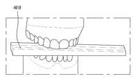
- FIG. 4is a view showing another part of the process of manufacturing a height-adjustable sprint according to an embodiment of the present invention.
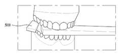
- FIG. 5is a view showing another part of the process of manufacturing a height-adjustable sprint according to an embodiment of the present invention.
- FIG. 6is a view showing another part of the process of manufacturing a height-adjustable sprint according to an embodiment of the present invention.
- FIG. 7is a diagram illustrating a pedestal to which an incisor region relationship recording apparatus generated through the process of FIGS. 3 to 6 is attached according to an embodiment of the present invention.
- FIG. 8is a view showing a state in which the left molar height adjusting bar and the right molar adjusting bar are separated from the pedestal to which the incisor region relationship recording device generated through the process of FIGS. 3 to 6 is attached according to an embodiment of the present invention.
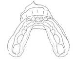
- FIG. 9is a bottom view of a pedestal to which the incisor portion relationship recording apparatus generated through the process of FIGS. 3 to 6 is attached according to an embodiment of the present invention.
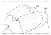
- FIG. 10is a view showing another part of the process of manufacturing a height-adjustable sprint according to an embodiment of the present invention.
- FIG. 11is a view showing a height adjustable sprint according to an embodiment of the present invention.
- FIG. 12is a view showing a height adjustable sprint according to an embodiment of the present invention.
- FIG. 13is a view showing a jaw joint balance device according to another embodiment of the present invention.
- FIG. 14is a view showing a change in the grip force of the user according to the change in the interval between the molar teeth of the jaw joint balance device according to another embodiment of the present invention.
- 15is a view illustrating a process of manufacturing a mouthpiece according to an embodiment of the present invention.
- 16is a view showing the height-adjustable sprint without the incisor portion according to an embodiment of the present invention.
- 17is a view showing the molar support portion of the height-adjustable sprint without the incisor portion according to an embodiment of the present invention.
- FIG. 18is a view showing the front teeth height adjustment according to another embodiment of the present invention.
- 19is a view showing a cross-section of the front tooth height adjustment according to another embodiment of the present invention.
- FIG. 20is a view showing a jaw joint balance device according to another embodiment of the present invention.
- 21is a view showing the molar pedestal height adjustment device according to an embodiment of the present invention.
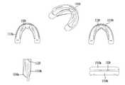
- FIG. 1is a view showing a pedestal of the height adjustable sprint according to an embodiment of the present invention and a six-side view thereof.
- 1includes a front view 1010, a back view 1020, a left side view 1030, a right side view 1040, a top view 1050, a bottom view 1060 of a pedestal 1000 of a height adjustable sprint. .
- the pedestal of the height-adjustable sprintmay be made of a silicon material or a material used for an existing sprint, and the hardness of the material may be changed as necessary.
- the baseis made of a structure in which the teeth of the upper jaw (upper jaw) or lower jaw (lower jaw) can be located.
- the pedestalhas a structure in which a thermosetting resin (EVA resin) such as a thermosetting resin or a thermoplastic resin can be filled.
- EVA resinthermosetting resin
- the pedestal of FIG. 1may be used on the upper jaw or the lower jaw, but for the convenience of description, a description will be given of a process of using the pedestal on the lower jaw.
- FIG. 2is a view showing the auxiliary pedestal of the height-adjustable sprint and a six-side view thereof according to an embodiment of the present invention.
- auxiliary pedestal 2000includes a front view 2010, a rear view 2020, a left side view 2030, a right side view 2040, a top view 2050, a bottom view 2060 of an auxiliary pedestal 2000 of a height adjustable sprint. do.
- the auxiliary pedestal 2000 of the height-adjustable sprintmay be made of a silicon material or a material used for an existing sprint, and the hardness of the material may be changed as necessary. Can be.
- the auxiliary pedestalis made of a structure that can be filled with a thermosetting resin (EVA resin) such as a thermosetting resin or a thermoplastic resin.
- EVA resinthermosetting resin
- auxiliary pedestal of Figure 2can be used in the upper jaw pedestal or lower jaw pedestal, for the convenience of description, it will be described as used in the lower jaw pedestal.
- FIG 3is a view showing a part of the process of manufacturing a height-adjustable sprint according to an embodiment of the present invention.
- thermoforming resin on the inner surface of the pedestal 1000is softened with hot water.
- a pedestal containing the softened thermosetting resinis placed on the tooth of the lower jaw (or the lower jaw gum where the toothless part is not). While holding a cotton roll (3010) or assembler on both molar teeth, the pedestal is pressed against the lower jaw to cure the thermoforming resin contained in the pedestal to complete the pedestal for the lower jaw.
- FIG. 4is a view showing another part of the process of manufacturing a height-adjustable sprint according to an embodiment of the present invention.
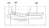
- the position of the front teeth height adjustment 4010 to determine the distance between the front teeth of the lower jaw and the upper jawis located in the front teeth.
- the front tooth height adjusting unitis represented using a wooden stick, but any type of device for measuring the distance at which the user feels comfortable while adjusting the height may be used.
- the userfeels the most comfortable, while increasing the number of the front height adjustment bars having a variety of thickness on the base of the front teeth. At this time, while moving the wooden stick to the left or right, the user feels the most comfort, or by measuring the force of the user's grip force, etc., determine the position and height of the largest size.
- the height of the incisor that the user feels most comfortablecan be determined by increasing or decreasing the height adjuster based on the height between the teeth of the molar to 4.1 millimeters.
- FIG. 5is a view showing another part of the process of manufacturing a height-adjustable sprint according to an embodiment of the present invention.
- the incisor height adjuster 5010 and the right molars height adjuster(not shown), the height between the left molars and the height between the right molars is determined. Position the left molar height guide and the right molar guide to hold.
- the left molar height adjuster and the right molar height adjustermay have various thicknesses so as to accurately measure the height between the left and right molars, respectively. While increasing the number of the left molar height and the right molar adjuster having such a variety of thickness, the left molar height guide and the right molar height guide to maintain the height between the two molar teeth are placed on each side of the molar.
- FIG. 6is a view showing another part of the process of manufacturing a height-adjustable sprint according to an embodiment of the present invention.
- the left molar height adjuster and the right molar height adjusterheld between the two molar teeth, while moving the front / back / left / right of the lower jaw, find the position where the user feels most comfortable (the strongest position).
- the relationship between the upper and lower jawis recorded using the incisor region relationship recording device 6010 (for example, dental impression material) in the incisor region.
- the incisor relationship recordmay be performed by placing and curing the softened thermoforming resin in the incisor region instead of the dental impression material.
- the incisor relationship recordis a record of the position between the teeth of the lower jaw and the incisor of the upper jaw, and is a record of the positions of the upper jaw and the lower jaw for which each user feels comfortable (the strongest force).
- FIG. 7is a diagram illustrating a pedestal to which an incisor region relationship recording apparatus generated through the process of FIGS. 3 to 6 is attached according to an embodiment of the present invention.
- FIG. 8is a view showing a state in which the left molar height adjusting bar and the right molar adjusting bar are separated from the pedestal to which the incisor region relationship recording device generated through the process of FIGS. 3 to 6 is attached according to an embodiment of the present invention.
- FIG. 9is a bottom view of a pedestal to which the incisor portion relationship recording apparatus generated through the process of FIGS. 3 to 6 is attached according to an embodiment of the present invention.
- FIG. 10is a view showing another part of the process of manufacturing a height-adjustable sprint according to an embodiment of the present invention.
- the auxiliary support 2000 described in FIG. 2is filled with a thermoforming resin, softened with hot water, and then placed on both molar portions of the pedestal 1000, respectively, and the incisor region relationship recording device 6010. ) Is placed on the lower jaw teeth (or lower jaw gum if some or all of the teeth are lost).
- thermoformed resin filled in the auxiliary pedestalis hardened in accordance with the respective pressures applied to both molar teeth. Therefore, even when the height between the left molar and the right molar differs, a height adjustable sprint reflecting the difference can be produced.
- the incisor height adjustment 4010may be used.
- the incisor height adjustment 4010when the upper and lower jaws are closed by placing the auxiliary pedestal 2000 and the incisor height adjuster 4010 together on the pedestal 1000.
- the sprintBy means of the pressure applied to both molar teeth, the sprint can be manufactured in such a way that the heights of both side pedestals are determined.
- the contour of the maxillary toothcan be repositioned to the correct position so that the position of 4010 can be accurately repositioned.
- the height adjustable sprint generated through the above-described processmay be used for different purposes. That is, the height-adjustable sprint generated through the above process may also be used for the purpose of the mouthpiece or the night guard.
- FIG. 11is a view showing a height adjustable sprint according to an embodiment of the present invention.
- FIG. 11illustrates a height adjustable sprint in which a height peculiar pedestal 2000 is attached to the pedestal 1000 according to the process of FIG. 10.
- FIG. 12is a view showing a height adjustable sprint according to an embodiment of the present invention.
- Figure 12shows a height adjustable sprint, separated from the lower jaw.
- FIG. 13is a view showing a jaw joint balance device according to another embodiment of the present invention.
- FIG. 13shows a perspective view 13000, a plan view 13100, a bottom view 13200, a side view 13300, and a front view 13400 of the jaw joint balancing device 1310.
- the jaw joint balance device shown in FIG. 13does not use thermoforming resin and does not adjust the height of the molar to an individual, but may be designed to have an optimal molar height that can be generally applied.
- the jaw joint balance device shown in Figure 13is similar in shape to a typical commercial jaw balance device, but the spacing between the molar teeth can be produced in 4.1 millimeters (4.1 mm). The spacing between the molars at this time may be produced based on the spacing when the user swallows saliva.
- Jaw joint balance deviceaccording to an embodiment of the present invention, the upper jaw teeth protector 1310a on which the upper jaw teeth are seated, the lower jaw teeth protector 1310b and / or upper jaw teeth protector 1310a on which the lower jaw teeth are seated; Located between the lower jaw teeth protector 1310b, and includes a tooth support 1320 having a thickness to maintain a constant gap between the molar of the upper jaw teeth and the molars of the lower jaw teeth.
- the tooth support 1320may have a thickness such that the gap between the molar of the upper jaw tooth and the molar of the lower jaw tooth maintains a gap in the range of 3.8 mm to 4.4 mm.
- the tooth rest 1320may be manufactured such that the spacing between the molars is 4.1 mm.
- the tooth support 1320may have a thickness such that the gap between the molar of the upper jaw tooth and the molar of the lower jaw tooth is maintained at a 4.1 mm interval.
- the spacing between the molars at this timemay be produced based on the spacing when the user swallows saliva.
- the tooth support 1320may be made of a material having elasticity. Accordingly, the tooth support 1320 may maintain the gap between the molar teeth by reflecting the pressure of the molar teeth or the change of the jaw joint.
- the upper jaw teeth protector 1310a and / or the lower jaw teeth protector 1310bmay be manufactured in a structure in which a thermosetting resin may be filled.
- tooth support portion 1320 of the molar regionin order to give a left and right height difference to the tooth support portion 1320 of the molar region, as shown in 2000 of Figure 11 may be manufactured to be coupled to the tooth support portion 1320 in the form of a male and female separately. .
- FIG. 14is a view showing a change in the grip force of the user according to the change in the interval between the molar teeth of the jaw joint balance device according to another embodiment of the present invention.
- the Applicantmeasured the change of the user's relative grip strength according to the spacing between the molar teeth in the existing jaw joint balance device.
- the experimentwas conducted in a manner that is measured only for a certain time every day.
- the gap between the molar teeth of the jaw joint balancerwas measured in 0.05 mm units and the grip force change was measured in 0.1 mm units where the grip force change was not significant.
- the gap between the molar teeth of the jaw joint balance devicetends to increase while the grip force of the user tends to increase, but the distance between the molar teeth of the jaw joint balance device is increased. This little increase, it can be seen that the grip force tends to decrease to about five magnitudes again. However, it can be seen that the grip force of most users increases rapidly when the spacing between the molars of the jaw joint balance device is about 4.1 mm.
- the gap between the molars of the jaw joint balance deviceexceeds 4.1 mm, if the continuous increase, the user's grip force is reduced to 10 mm.
- the spacing between the molar teeth of the jaw joint balance deviceexceeds 10 mm, since the user began to feel discomfort in the jaw joint, the measurement for this cannot be a meaningful experimental result, and thus was excluded.
- the present inventionproposes a jaw joint device such as a sprint, a mouthpiece, a night guard, and the spacing between the molar teeth is 4.1 mm.
- 15is a view illustrating a process of manufacturing a mouthpiece according to an embodiment of the present invention.
- the mouthpiece for preventing injury during exerciseAs shown in Figure 15, while stacking the left and right molar height adjusters 15010, 15020 having a thickness of 0.1mm or 0.05mm, left / right The height of the occlusal surface between the molar teeth is measured directly in the oral cavity. At this time, the interval between the left and right molar is the first priority to select the height at which the user feels comfortable, but with reference to the experimental results of FIG. 14 described above, the height within the error interval of 4.1 mm to 0.4 mm as a reference value Can do it.
- the lower jaw position where the user feels comfortableis set.
- the incisor region relationship recording devicefor example, dental impression agent
- a pattern of the height between the incisorsis made, and the molar area relationship recording device (for example, in the molar region) is placed in the mouth again.
- a dental impression agentis used to complete an entire tooth height record.
- the impression of the upper jaw and the lower jawis made and a plaster model is made.
- the mouthpieceis completed after mounting the articulator using a pre-produced interdental height record.
- the above-described height-adjustable sprint and manufacturing method thereofmay be applied to a mouthpiece or a night guard. That is, in the case of the general mouthpiece, the height of 4.1 mm prepared previously is clamped between left and right molar teeth. Then, soften the upper jaw device (EVA resin) without the measurement site of the molar teeth with hot water, and insert a hole attachment for breathing in the front teeth area between the front teeth and bite together to complete the device. The molar height pad corresponding to the molar height is softened with hot water and combined with the prefabricated front device to complete the general mouthguard.
- EVA resinupper jaw device
- the mouthpiececan be manufactured so that the spacing between the molars on both sides can have a slight difference.
- the mouthpiececan be manufactured so that the spacing between the left molars is 4.1 mm and the spacing between the right molars is 4.55 mm.
- the occlusal height between the left and right molar teethis measured directly in the oral cavity, with a 0.05 mm sheet stacked (approximately 4.1 mm).
- bite the left and right measurement papersto the molar in the mouth, and use the dental impression agent on the front teeth to make a height pattern between the front teeth.
- a dental impression agentis used on the molar area to complete the entire interdental height record.
- a plaster modelis made.
- the pre-protooth height recordis then used to mount the articulator to complete the professional mouthpiece.
- a prefabricated 4.1 mm heightis sandwiched between the left and right molar teeth.
- EVA resinmolar area device
- the night guardmay be manufactured so that the spacing between the molars on both sides may have a slight difference.
- the night guardcan be manufactured so that the spacing between the left molars is 4.1 mm and the spacing between the right molars is 4.55 mm.
- 16is a view showing the height-adjustable sprint without the incisor portion according to an embodiment of the present invention.
- the height-adjustable sprint without an incisoris composed of a device that covers the molar area and is made of titanium molybdenum wire (TMA) or stainless steel wire for the purpose of reinforcement of the incisor of the device and adjustment and expansion according to individual condition. Reinforce.
- TMAtitanium molybdenum wire
- stainless steel wirefor the purpose of reinforcement of the incisor of the device and adjustment and expansion according to individual condition. Reinforce.
- the height-adjustable sprint without the incisor portionmay include a molar pedestal 1610 and / or an incisor pedestal 1620 that can adjust the spacing between molar teeth.
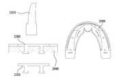
- 17is a view showing the molar support portion of the height-adjustable sprint without the incisor portion according to an embodiment of the present invention.
- the height-adjustable sprint without the incisor portionis the incisor support 7000 reinforced with metal for shape retention and lateral expansion, the upper jaw tooth palate support 7100 supporting the upper jaw in close contact with the palatal surface of the upper jaw, and between the molars Located on the occlusal surface, the molar support 7200 supporting the molar and / or the lower surface of the lower jaw tooth lingual support 7300 in close contact with the inner surface of the lower jaw tooth.
- the molar pedestal portion of the height-adjustable sprint without the aforementioned incisor portionmay be manufactured in a form without a slope, a form with a slope, and / or a change in thickness.
- the molar pedestal 7200may be manufactured parallel to the tooth occlusal surface in the case of the shape without the inclination.
- the molar support portion 7200is inclined 5-10 degrees in the downward or upward direction for the purpose of expanding the upper and lower teeth and the arch, in the case of the shape having the inclination so that it can be expanded by the chewing force. do.
- Molar support portion 7200in the form of a change in thickness, as shown, the inner thickness is thick, the thickness can be made in the form becomes thinner toward the outside to move the lower jaw forward or backward If you move it, it can be made thinner or thicker in the future. Its action is done automatically by the user's saliva swallowing force (usually 2kg / 2000 times a day) and can be treated by the change of direction following the change of inclination and thickness.
- the area in contact with the lower teeth (bottom 7200)can be retained in the teeth using a thermoplastic resin.
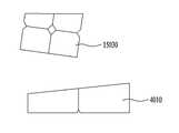
- FIG. 18is a view showing the front teeth height adjustment according to another embodiment of the present invention.
- the front tooth height adjustermay be manufactured in the form of a stick, the thickness of the right side is the thickest, the thickness can be made in the form becomes thinner toward the left.
- the incisor height adjuster of this typeWhile moving the incisor height adjuster of this type to the left or right direction, it is possible to determine the height at which the user feels most biased. Alternatively, the user's grip force and the like may be measured by moving the incisor height adjustment lever in the left or right direction, and the thickness of the incisor height adjustment position at the position where the measurement value is the highest may be determined as the interval between the incisors.
- the upper teeth height adjuster 15030 shown abovecan be located directly between the front teeth to find a good position of the left and right jaws.
- the incisor height adjuster 4010 shown at the bottomis a device that reduces the overall thickness by reflecting the thickness of the EVA resin device (for example, pedestal 1000) between the incisors.
- 19is a view showing a cross-section of the front tooth height adjustment according to another embodiment of the present invention.
- the front tooth height adjusting devicemay include a rear surface positioned inside the mouth and a front surface positioned outside the mouth. Referring to the cross-section of the incisor height adjuster, the thickness can be reduced by moving from the front to the rear of the incisor height adjuster.
- the front tooth height adjuster of this typeWhile moving the front tooth height adjuster of this type in the forward or backward direction, it is possible to determine the height at which the user feels most comfortable. Alternatively, the user's grip force and the like may be measured while moving the front tooth height adjusting arm in the front or rear direction, and the thickness of the front tooth height adjusting arm at the position where the measurement value is the highest may be determined as the interval between the front teeth.
- FIG. 20is a view showing a mouthpiece according to another embodiment of the present invention.
- the mouthpiece 20000includes a left molar pedestal 20010a that maintains a gap between a left upper jaw molten and a left lower jaw molars, a right molar that maintains a gap between a right upper jaw molar and a right lower jaw molar.
- Pedestal 20010b, and / or incidence pedestal 20020that maintains a gap between the upper jaw incisor and the lower jaw incisor.
- the left molar pedestal and the right molar pedestalmay be manufactured so that the interval between the left molar is 4.1 mm and the right molar is 4.55 mm, respectively.
- the front tooth pedestal 2020may be manufactured in a form in which the thickness decreases from left to right or in a form in which the thickness decreases from the right to the left.
- 21is a view showing the molar pedestal height adjustment device according to an embodiment of the present invention.
- Molar pedestal height adjustment device 21000may be applied to jaw joint balance device 1310 or mouthpiece 20000 described above.
- the molar pedestal height adjusting device 21000will be described in detail based on the drawings applied to the mouthpiece 20000.
- the molar pedestal height adjusting device 21000is coupled to the top or bottom of the molar pedestal of the mouthpiece 20000 to connect the mouthpiece. You can adjust the spacing between the molars of your users.
- the mouthpiececan have a hole (arm role), and the molar pedestal height adjusting device 21000 is shown in side view 21020 of the mouthpiece. It can have a device (male role) that is coupled to the hole.
- Molar pedestal height adjustment device 21000can be manufactured in a variety of thicknesses.
- the distance between the left or right molarcan be adjusted separately.
- the inventionis applicable throughout the field of jaw joint correction, jaw joint protection, exercise aids and / or tooth protection.
Landscapes
- Health & Medical Sciences (AREA)
- General Health & Medical Sciences (AREA)
- Life Sciences & Earth Sciences (AREA)
- Veterinary Medicine (AREA)
- Public Health (AREA)
- Animal Behavior & Ethology (AREA)
- Oral & Maxillofacial Surgery (AREA)
- Vascular Medicine (AREA)
- Heart & Thoracic Surgery (AREA)
- Biomedical Technology (AREA)
- Engineering & Computer Science (AREA)
- Orthopedic Medicine & Surgery (AREA)
- Nursing (AREA)
- Dentistry (AREA)
- Epidemiology (AREA)
- Physical Education & Sports Medicine (AREA)
- Dental Tools And Instruments Or Auxiliary Dental Instruments (AREA)
- Orthopedics, Nursing, And Contraception (AREA)
Abstract
Description
Translated fromKorean본 발명은 높이 조절 가능한 스프린트 및 이를 제작하는 방법에 관한 것이다. 보다 상세하게는, 본 발명은 개인의 턱 관절에 맞는 높이를 가지는 스프린트 및 이를 제작하는 방법에 관한 것이다.The present invention relates to a height adjustable sprint and a method of manufacturing the same. More specifically, the present invention relates to a sprint having a height that fits the jaw joint of an individual and a method of manufacturing the same.
턱 관절은, 입을 벌리거나 닫는 운동과 하악골의 회전 중심이 되는 관절로서 회전 운동과 활주 운동이 일어나는 관절 부위이다. 턱 관절은 좌측 턱 관절과, 우측 턱 관절이 동시에 운동을 수행하여야 한다. 즉, 턱 관절을 이용하여, 음식물 등을 씹는 저작 운동, 또는 발음을 위한 상하 운동을 위하여는, 좌측 턱 관절과 우측 턱 관절이 동시에 움직여야 한다. 따라서, 턱 관절은, 한쪽 부위의 턱 관절에 문제가 생기면, 다른 부위의 턱 관절에도 문제가 발생할 수 밖에 없는 구조로 되어 있다. 따라서, 턱 관절에 문제가 생기면, 좌측 턱 관절과 우측 턱 관절이 균형을 이룰 수 있는 방향의 치료가 필요하다.The jaw joint is a joint that serves as a center of rotation of the mouth and the mouth opening and closing and the mandible, and is a joint part where rotational motion and sliding motion occur. In the jaw joint, the left jaw joint and the right jaw joint should exercise simultaneously. That is, using the jaw joint, the left jaw joint and the right jaw joint should be moved simultaneously for chewing movement of food or the like or vertical movement for pronunciation. Therefore, when the jaw joint has a problem with the jaw joint of one part, the jaw joint has a structure which inevitably causes a problem with the jaw joint of the other part. Therefore, when a problem occurs in the jaw joint, treatment in a direction in which the left and right jaw joints can be balanced is required.
한편, 턱 관절 부근은, 12개의 뇌신경 중 9개가 지나가고, 수많은 혈관, 임파, 및 신경 등이 분포하는 중요한 부분이다. 따라서, 턱 관절의 불균형은 상부 경추가 이탈하는 원인이 될 수 있다. 이는 턱 관절과 연관된 근육 밸런스는 물론 중추 신경계의 혼란과 더불어 정상적인 머리뼈의 움직임을 방해하여 전신적인 신경계의 혼란을 일으키는 원인이 된다. 이러한 전신적인 신경계의 혼란은, 척추관절 및 근골격계의 질환뿐만 아니라, 두통, 어지럼증, 순환기 질환, 이비인후과 질환, 비뇨생식기질환, 호흡기 질환, 성장장애, 및 운동장애 (틱 장애, 뚜렛장애, 파킨슨씨병) 등 광범위한 전신 병적 증상을 발생시킨다.On the other hand, in the vicinity of the jaw joint, nine out of twelve cranial nerves pass, and an important part in which numerous blood vessels, lymph nodes, and nerves are distributed. Thus, imbalance of the jaw joint may cause the upper cervical spine to dislodge. This causes disruption of the central nervous system as well as muscle balance associated with the jaw joints and disrupts normal head bone movement, causing systemic nervous system confusion. Such systemic nervous system disorders include not only diseases of the vertebral joints and musculoskeletal systems, but also headaches, dizziness, circulatory diseases, otolaryngology diseases, genitourinary diseases, respiratory diseases, growth disorders, and movement disorders (tic disorders, Tourette disorders, Parkinson's disease). It causes a wide range of systemic symptoms.
턱 관절의 불균형은 각 개인의 생활 습관이나, 스트레스와 같은 개인 주변의 외적 상황에 의하여 발생하는 경우가 많다. 따라서, 턱 관절의 불균형 정도는 개인에 따라 다르며, 특히, 좌측 턱 관절과 우측 턱 관절의 불균형의 정도는 각 개인에 따라 그 편차가 다르다.Imbalances in the jaw joints are often caused by external circumstances around the individual, such as their lifestyle or stress. Therefore, the degree of imbalance of the jaw joint varies from person to person, and in particular, the degree of imbalance between the left and right jaw joints varies depending on each person.
종래에는 치과 전문의와 같은, 특수 전문가에 의해서, 각 개인의 좌/우측 턱 관절의 불균형에 따른 어금니 높이의 차이를 조절하여 스프린트를 제작하여야 했다.Conventionally, a specialty specialist, such as a dentist, has to produce a sprint by adjusting the difference in the molar height according to the imbalance of the left and right jaw joints of each individual.
또한, 종래에 존재하던 턱 관절 균형 장치는, 개인의 좌측 턱 관절과 우측 턱 관절의 불균형을 고려하지 않고, 정형화된 규격을 가지도록 설계되었다. 따라서, 어금니의 높이를 일정 높이에 맞추게 되어, 종래에 존재하던 턱 관절 균형 장치로는, 좌/우측 턱 관절 사이의 비대칭이 심해 아래턱이 많이 틀어진 경우, 또는 한쪽의 일부 혹은 치아상실로 좌우 씹는 높이의 차이가 많이 나는 경우에는 효과적인 치료효과를 얻을 수 없는 문제점이 있었다.In addition, the existing jaw joint balancing device is designed to have a standardized specification without considering the imbalance between the left and right jaw joints of the individual. Therefore, the height of the molars is adjusted to a certain height, and as a conventional jaw joint balancing device, the asymmetry between the left and right jaw joints is severe and the lower jaw is twisted a lot, or the height of the left and right chewing by one part or the loss of teeth If there is a lot of difference between the effective treatment effect was not obtained.
또한, 종래에 존재하던 턱 관절 균형 장치는, 한쪽의 치아를 전부 상실하여 아래턱에서 유지를 얻을 수 없는 경우, 윗 턱 (상악) 이나 아래 턱 (하악) 중 한쪽의 치아가 전부 없는 경우, 좌우 씹는 높이가 많이 낮아 진 경우, 앞니를 모두 상실되고 어금니만 있는 경우, 구강 내 모든 치아가 전부 없는 무치악에서는 장치 제작이 불가능 하다는 문제점이 있었다.In addition, the jaw joint balance device that has existed in the past, when the loss of all of one tooth can not be obtained from the lower jaw, when the teeth of one of the upper jaw (upper jaw) or lower jaw (lower jaw) is missing, left and right chewing When the height is lowered a lot, if all the front teeth are lost and there are only molar teeth, there was a problem that the device production is impossible in the edentulous jaw without all the teeth in the oral cavity.
본 발명이 이루고자 하는 기술적 과제는, 전술한 문제점을 해결하기 위한 것으로, 치과 전문가의 도움 없이도, 일정한 효과를 얻을 수 있는, 사용자 개인의 턱 관절 상태에 맞는, 높이 조절형 스프린트를 제작하는 것에 있다.The technical problem to be solved by the present invention is to solve the above-mentioned problems, and to produce a height-adjustable sprint that is suitable for a user's jaw joint state, which can achieve a certain effect without the help of a dental specialist.
전술한 기술적 과제를 해결하기 위하여 본 발명의 일 실시예에 따른 높이 조절형 스프린트는, 열성형수지가 채워질 수 있는 구조로, 아래턱 치아가 안착되는 받침대 (1000), 상기 아래턱 치아의 앞니가 위치하는, 상기 받침대 (1000) 의 앞니 부분의 상부에서, 윗턱 치아의 앞니와 상기 받침대 (1000)가 안착된 상기 아래턱 치아의 앞니의 간격을 고정하는 앞니 부위 관계 기록 장치 (6010) 및 성형 재료가 채워질 수 있는 구조로, 상기 아래턱 치아의 어금니가 위치하는, 상기 받침대 (1000) 의 어금니 부분의 상부에 안착되는 보조 받침대 (2000);를 포함하며, 여기서, 상기 보조 받침대 (2000)는, 상기 앞니 부위 관계 기록 장치 (6010) 가 나타내는 윗턱과 아래턱의 위치에 의하여, 상기 아래턱 치아의 어금니와 상기 윗턱 치아의 어금니에 가해지는 압력에 따라, 상기 보조 받침대 (2000) 가 상기 받침대 (1000) 위에 안착되는 높이가 결정되는 것을 특징으로 한다.In order to solve the above technical problem, the height-adjustable sprint according to an embodiment of the present invention is a structure that can be filled with a thermoforming resin, the
바람직하게는, 상기 앞니 부위 관계 기록 장치 (6010)는, 상기 아래턱 치아의 어금니와 상기 윗턱 치아의 어금니 사이의 간격이 3.8 mm 에서 4.5 mm 사이의 범위의 간격을 유지하는, 상기 받침대 (1000) 의 앞니 부분과 상기 윗턱 치아의 앞니의 간격을 고정하는 것을 특징으로 한다.Preferably, the incisor region relationship recording
바람직하게는, 상기 앞니 부위 관계 기록 장치 (6010)는, 상기 왼쪽 아래턱 치아의 어금니와 상기 윗턱 치아의 어금니 사이의 간격이 4.1 mm 간격을 유지하는, 상기 받침대 (1000) 의 앞니 부분과 상기 윗턱 치아의 앞니의 간격을 고정하는 것을 특징으로 한다.Preferably, the incisor region
바람직하게는, 상기 받침대 (1000) 및/또는 상기 보조 받침대 (2000)는, 탄성을 가지는 재질로 제작된 것을 특징으로 한다.Preferably, the
바람직하게는, 상기 앞니 부위 관계 기록 장치 (6010)는, 스틱 형태로 제작되어, 우측의 두께가 가장 두껍고, 좌측으로 갈수록 두께가 얇아지는 형태의 앞니 높이 조절대 (4010)으로 구비되는 것을 특징으로 한다.Preferably, the incisor portion
바람직하게는, 상기 성형 재료는, 열 성형수지 (EVA 수지) 또는 비닐폴리실옥산 (vinylpolysiloxane) 인 것을 특징으로 한다.Preferably, the molding material is characterized in that the thermoforming resin (EVA resin) or vinyl polysiloxane (vinylpolysiloxane).
본 발명의 다른 실시예에 따른, 턱 관절 균형 장치는, 윗턱 치아가 안착되는 윗턱 치아 보호부 (1310a), 아래턱 치아가 안착되는 아래턱 치아 보호부 (1310b) 및 상기 윗턱 치아 보호부 (1310a)와 상기 아래턱 치아 보호부 (1310b) 사이에 위치하며, 상기 윗턱 치아의 어금니와 상기 아래턱 치아의 어금니 사이의 간격이 어금니의 지지부 재질의 경도에 따라 3.8 mm 에서 4.5 mm 사이의 범위의 간격을 유지하도록 하는 두께를 가지는 치아 받침부 (1320)를 포함한다.According to another embodiment of the present invention, the jaw joint balancing device, the upper
바람직하게는. 상기 치아 받침부 (1320)는, 탄성을 가지는 재질로 제작된 것을 특징으로 한다.Preferably. The
바람직하게는, 상기 치아 받침부 (1320)는, 상기 윗턱 치아의 어금니와 상기 아래턱 치아의 어금니 사이의 간격이 4.1 mm 의 간격을 유지하도록 하는 두께를 가지는 것을 특징으로 한다..Preferably, the
바람직하게는, 상기 윗턱 치아 보호부 (1310a) 및/또는 상기 아래턱 치아 보호부 (1310b)는, 열성형수지가 채워질 수 있는 구조로 제작된 것을 특징으로 한다.Preferably, the upper
바람직하게는, 상기 치아 받침부 (1320)에 결합되어, 좌측 또는 우측 어금니 사이의 간격을 각각 조절하는 어금니 받침대 높이 조절 장치 (21000)를 더 포함하며, 상기 치아 받침부 (1320) 와 상기 어금니 받침대 높이 조절 장치 (21000) 는 서로 결합될 수 있는 암/수의 결합부를 포함하는 것을 특징으로 한다.Preferably, it further comprises a molar pedestal
본 발명의 다른 실시예에 따른, 앞니 부위가 없는 턱관절 균형 장치는, 형태 유지 및 측방 확장을 위해 금속으로 보강된 앞니 지지부 (7000), 윗턱 치아의 구개면에 밀착되어, 윗턱을 지지하는 윗턱 치아 구개 지지부 (7100) 및 어금니 사이 교합면에 위치하여, 어금니를 지지하는 어금니 받침부 (7200)를 포함한다.According to another embodiment of the present invention, the jaw joint balance device without the incisor portion is the upper jaw supporting the upper jaw in close contact with the palatal surface of the
바람직하게는, 상기 어금니 받침부 (7200)는, 아래 방향 또는 윗 방향으로 경사를 가지는 형태로 제작된 것을 특징으로 한다.Preferably, the
바람직하게는, 상기 어금니 받침부 (7200)는, 안쪽의 두께가 두껍고, 바깥쪽으로 갈수록 두께가 얇아지거나, 앞뒤로 두께차이에 차이가 나는 형태로 제작된 것을 특징으로 한다.Preferably, the
본 발명의 일 실시예에 따른 스포츠용 마우스 가드는, 좌측 윗턱 어금니와 좌측 아래턱 어금니 사이의 간격을 유지하는 좌측 어금니 받침대 (20010a), 우측 윗턱 어금니와 우측 아래턱 어금니 사이의 간격을 유지하는 우측 어금니 받침대 (20010b) 및 윗턱 앞니와 아래턱 앞니 사이의 간격을 유지하는 앞니 받침대 (20020)를 포함한다.The sport mouse guard according to an embodiment of the present invention, the left
바람직하게는, 상기 좌측 어금니 받침대 (20010a) 또는 상기 우측 어금니 받침대 (20010b)에 결합되어, 좌측 또는 우측 어금니 사이의 간격을 각각 조절하는 어금니 받침대 높이 조절 장치 (21000)를 더 포함하며, 상기 상기 좌측 어금니 받침대 (20010a) 또는 상기 우측 어금니 받침대 (20010b) 와, 상기 어금니 받침대 높이 조절 장치 (21000) 는 서로 결합될 수 있는 암/수의 결합부를 포함하는 것을 특징으로 한다.Preferably, the left molar pedestal (20010a) or the right molar pedestal (20010b) is coupled to, further comprising a molar pedestal height adjustment device (21000) for adjusting the interval between the left or right molar, respectively, the left The
바람직하게는, 상기 측 어금니 받침대 (2010a) 및 상기 우측 어금니 받침대 (2010b)는, 상기 어금니 사이 간격이 좌측 4.1 mm과 우측 4.55mm을 갖도록 하는 두께를 가지는 것을 특징으로 한다.Preferably, the side molar pedestal 2010a and the right molar pedestal 2010b have a thickness such that the spacing between the molars has a left side of 4.1 mm and a right side of 4.55 mm.
본 발명에 따르면, 사용자 개인의 좌/우측 턱 관절의 높이 차를 고려한 스프린트 제작이 용이하다는 효과가 있다.According to the present invention, there is an effect that it is easy to manufacture a sprint considering the height difference of the left and right jaw joint of the user.
본 발명에 따르면, 사용자 개인의 치아 상태와 관계없이, 스프린트를 제작할 수 있는 효과가 있다.According to the present invention, there is an effect that can produce a sprint irrespective of the dental state of the user.
본 발명에 따르면, 전문가의 도움 없이도, 각 개인이 저렴한 비용으로, 개인에 맞는 스프린트를 제작할 수 있는 효과가 있다.According to the present invention, even without the help of an expert, each individual can produce a sprint for each individual at a low cost.
도 1은 본 발명의 일 실시예에 따른 높이 조절형 스프린트의 받침대 및 이의 육면도를 나타낸 도면이다.1 is a view showing a pedestal of the height adjustable sprint according to an embodiment of the present invention and a six-side view thereof.
도 2는 본 발명의 일 실시예에 따른, 높이 조절형 스프린트의 보조 받침대 및 이의 육면도를 나타낸 도면이다.2 is a view showing the auxiliary pedestal of the height-adjustable sprint and a six-side view thereof according to an embodiment of the present invention.
도 3은 본 발명의 일 실시예에 따른, 높이 조절형 스프린트를 제작하는 과정의 일부를 나타낸 도면이다.3 is a view showing a part of the process of manufacturing a height-adjustable sprint according to an embodiment of the present invention.
도 4는 본 발명의 일 실시예에 따른, 높이 조절형 스프린트를 제작하는 과정의 다른 일부를 나타낸 도면이다.4 is a view showing another part of the process of manufacturing a height-adjustable sprint according to an embodiment of the present invention.
도 5는 본 발명의 일 실시예에 따른, 높이 조절형 스프린트를 제작하는 과정의 다른 일부를 나타낸 도면이다.5 is a view showing another part of the process of manufacturing a height-adjustable sprint according to an embodiment of the present invention.
도 6은 본 발명의 일 실시예에 따른, 높이 조절형 스프린트를 제작하는 과정의 다른 일부를 나타낸 도면이다.6 is a view showing another part of the process of manufacturing a height-adjustable sprint according to an embodiment of the present invention.
도 7은 본 발명의 일 실시예에 따른, 도 3 내지 도 6의 과정을 거쳐 생성된 앞니 부위 관계 기록 장치가 부착된 받침대를 나타낸 도면이다.FIG. 7 is a diagram illustrating a pedestal to which an incisor region relationship recording apparatus generated through the process of FIGS. 3 to 6 is attached according to an embodiment of the present invention.
도 8은 본 발명의 일 실시예에 따른, 도 3 내지 도 6의 과정을 거쳐 생성된 앞니 부위 관계 기록 장치가 부착된 받침대에서 좌측 어금니 높이 조절대 및 우측 어금니 조절대가 분리된 상태를 나타낸 도면이다.8 is a view showing a state in which the left molar height adjusting bar and the right molar adjusting bar are separated from the pedestal to which the incisor region relationship recording device generated through the process of FIGS. 3 to 6 is attached according to an embodiment of the present invention. .
도 9는 본 발명의 일 실시예에 따른, 도 3 내지 도 6의 과정을 거쳐 생성된 앞니 부위 관계 기록 장치가 부착된 받침대의 저면도를 나타낸 도면이다.FIG. 9 is a bottom view of a pedestal to which the incisor portion relationship recording apparatus generated through the process of FIGS. 3 to 6 is attached according to an embodiment of the present invention.
도 10은 본 발명의 일 실시예에 따른, 높이 조절형 스프린트를 제작하는 과정의 다른 일부를 나타낸 도면이다.10 is a view showing another part of the process of manufacturing a height-adjustable sprint according to an embodiment of the present invention.
도 11은 본 발명이 일 실시예에 따른, 높이 조절형 스프린트를 나타낸 도면이다.11 is a view showing a height adjustable sprint according to an embodiment of the present invention.
도 12는 본 발명의 일 실시예에 따른, 높이 조절형 스프린트를 나타낸 도면이다.12 is a view showing a height adjustable sprint according to an embodiment of the present invention.
도 13은 본 발명의 다른 실시예에 따른, 턱 관절 균형 장치를 나타낸 도면이다.13 is a view showing a jaw joint balance device according to another embodiment of the present invention.
도 14는 본 발명의 다른 실시예에 따른, 턱 관절 균형 장치의 어금니 사이의 간격의 변화에 따른 사용자의 악력의 변화를 나타낸 도면이다.14 is a view showing a change in the grip force of the user according to the change in the interval between the molar teeth of the jaw joint balance device according to another embodiment of the present invention.
도 15는 본 발명의 일 실시예에 따른, 마우스 피스를 제작하는 과정을 나타낸 도면이다.15 is a view illustrating a process of manufacturing a mouthpiece according to an embodiment of the present invention.
도 16 은 본 발명의 일 실시예에 따른 앞니 부위가 없는 높이 조절형 스프린트를 나타낸 도면이다.16 is a view showing the height-adjustable sprint without the incisor portion according to an embodiment of the present invention.
도 17 은 본 발명의 일 실시예에 따른, 앞니 부위가 없는 높이 조절형 스프린트의 어금니 받침부를 나타낸 도면이다.17 is a view showing the molar support portion of the height-adjustable sprint without the incisor portion according to an embodiment of the present invention.
도 18 은 본 발명의 다른 실시예에 따른, 앞니 높이 조절대를 나타낸 도면이다.18 is a view showing the front teeth height adjustment according to another embodiment of the present invention.
도 19 는 본 발명의 다른 실시예에 따른, 앞니 높이 조절대의 단면을 나타낸 도면이다.19 is a view showing a cross-section of the front tooth height adjustment according to another embodiment of the present invention.
도 20은 본 발명의 다른 실시예에 따른, 턱 관절 균형 장치를 나타낸 도면이다.20 is a view showing a jaw joint balance device according to another embodiment of the present invention.
도 21은 본 발명의 일 실시예에 따른 어금니 받침대 높이 조절 장치를 나타낸 도면이다.21 is a view showing the molar pedestal height adjustment device according to an embodiment of the present invention.
이하 첨부 도면들 및 첨부 도면들에 기재된 내용들을 참조하여 본 발명의 실시예를 상세하게 설명하지만, 본 발명이 실시예들에 의해 제한되거나 한정되는 것은 아니다.Hereinafter, embodiments of the present invention will be described in detail with reference to the accompanying drawings and the contents described in the accompanying drawings, but the present invention is not limited or limited to the embodiments.
본 명세서에서 사용되는 용어는 본 발명에서의 기능을 고려하면서 가능한 현재 널리 사용되는 일반적인 용어를 선택하였으나, 이는 당분야에 종사하는 기술자의 의도 또는 관례 또는 새로운 기술의 출현 등에 따라 달라질 수 있다. 또한, 특정한 경우는 출원인이 임의로 선정한 용어도 있으며, 이 경우 해당되는 발명의 설명 부분에서 그 의미를 기재할 것이다. 따라서 본 명세서에서 사용되는 용어는, 단순한 용어의 명칭이 아닌 그 용어가 가지는 실질적인 의미와 본 명세서의 전반에 걸친 내용을 토대로 해석되어야 함을 밝혀두고자 한다.The terminology used herein is a general term that is widely used as possible while considering functions in the present invention, but may vary according to the intention or custom of a person skilled in the art or the emergence of a new technology. In addition, in certain cases, there is a term arbitrarily selected by the applicant, and in this case, the meaning will be described in the corresponding description of the invention. Therefore, it is to be understood that the terminology used herein is to be interpreted based on the actual meaning of the term and the contents throughout the specification, rather than simply on the name of the term.
도 1은 본 발명의 일 실시예에 따른 높이 조절형 스프린트의 받침대 및 이의 육면도를 나타낸 도면이다.1 is a view showing a pedestal of the height adjustable sprint according to an embodiment of the present invention and a six-side view thereof.
도 1은 높이 조절형 스프린트의 받침대 (1000)의 정면도 (1010), 배면도 (1020), 좌측면도 (1030), 우측면도 (1040), 평면도 (1050), 저면도 (1060)를 포함한다.1 includes a
본 발명의 일 실시예에 따른, 높이 조절형 스프린트의 받침대는 실리콘 재질 또는 기존의 스프린트에 사용되는 재질로 제작될 수 있으며, 해당 재질의 경도 [硬度, hardness] 는 필요에 따라 변경될 수 있다.According to one embodiment of the present invention, the pedestal of the height-adjustable sprint may be made of a silicon material or a material used for an existing sprint, and the hardness of the material may be changed as necessary.
도 1의 정면도 (1010) 및 저면도 (1060)을 참조하면, 받침대는 윗턱 (상악) 또는 아래턱 (하악)의 치아가 위치할 수 있는 구조로 이루어진다. 또한, 받침대는 열경화성 수지 또는 열가소성 수지와 같은 열성형수지 (EVA 수지)가 채워질 수 있는 구조로 이루어진다.Referring to the
도 1의 받침대는 윗턱 또는 아래턱에 사용될 수 있으나, 본원에서는 설명의 편의를 위하여, 아래턱에 받침대를 사용하는 과정에 대하여 설명하고자 한다.The pedestal of FIG. 1 may be used on the upper jaw or the lower jaw, but for the convenience of description, a description will be given of a process of using the pedestal on the lower jaw.
도 2는 본 발명의 일 실시예에 따른, 높이 조절형 스프린트의 보조 받침대 및 이의 육면도를 나타낸 도면이다.2 is a view showing the auxiliary pedestal of the height-adjustable sprint and a six-side view thereof according to an embodiment of the present invention.
도 2는 높이 조절형 스프린트의 보조 받침대 (2000) 의 정면도 (2010), 배면도 (2020), 좌측면도 (2030), 우측면도 (2040), 평면도 (2050), 저면도 (2060)를 포함한다.2 includes a
본 발명의 일 실시예에 따른, 높이 조절형 스프린트의 보조 받침대 (2000)는 실리콘 재질 또는 기존의 스프린트에 사용되는 재질로 제작될 수 있으며, 해당 재질의 경도 [硬度, hardness] 는 필요에 따라 변경될 수 있다.According to an embodiment of the present invention, the
도 2의 정면도 (2010) 및 저면도 (2060)을 참조하면, 보조 받침대는 열경화성 수지 또는 열가소성 수지와 같은 열성형수지 (EVA 수지)가 채워질 수 있는 구조로 이루어진다.Referring to the
도 2의 보조 받침대는 윗턱 받침대 또는 아래턱 받침대에 사용될 수 있으나, 본원에서는 설명의 편의를 위하여, 아래턱 받침대에 사용되는 것으로 설명한다.Although the auxiliary pedestal of Figure 2 can be used in the upper jaw pedestal or lower jaw pedestal, for the convenience of description, it will be described as used in the lower jaw pedestal.
도 3은 본 발명의 일 실시예에 따른, 높이 조절형 스프린트를 제작하는 과정의 일부를 나타낸 도면이다.3 is a view showing a part of the process of manufacturing a height-adjustable sprint according to an embodiment of the present invention.
도 3을 참조하면, 받침대 (1000)의 내면의 열성형수지를 뜨거운 물로 연화한다. 연화된 열성형수지를 포함하는 받침대를 아래턱의 치아 (또는 치아가 없는 부분은 아래턱 잇몸)에 위치시킨다. 코튼 롤 (cotton roll; 3010) 혹은 설합자를 양쪽 어금니에 물면서, 받침대를 아래턱에 압접하여, 받침대에 포함된 열성형수지를 경화하여, 아래턱을 위한 받침대를 완성한다.Referring to FIG. 3, the thermoforming resin on the inner surface of the
도 4는 본 발명의 일 실시예에 따른, 높이 조절형 스프린트를 제작하는 과정의 다른 일부를 나타낸 도면이다.4 is a view showing another part of the process of manufacturing a height-adjustable sprint according to an embodiment of the present invention.
도 3의 과정을 통하여 완성한 받침대를 아래턱에 부착한 상태에서, 아래턱의 앞니와 윗턱의 앞니 사이의 거리를 결정하는 앞니 높이 조절대 (4010)를 앞니에 위치 시킨다. 도 4에서는 앞니 높이 조절대를 나무 스틱을 사용하여 표현하였으나, 높이를 조절하면서, 사용자가 편안함을 느끼는 거리를 측정하기 위한 어떠한 장치 형태라도 사용가능하다.In the state attached to the lower jaw completed through the process of Figure 3, the position of the front
도 4를 참조하면, 대략적인 앞니 사이의 높이를 결정하기 위해 앞니 부위의 받침대 위에, 다양한 두께를 가지는 앞니 높이 조절대의 개수를 증가시키면서, 사용자가 가장 편안함을 느끼는 앞니의 높이를 결정한다. 이때, 나무 스틱을 좌우로 이동시키면서 사용자가 가장 편안함을 느끼거나, 사용자의 악력 등의 힘을 측정하여, 그 크기가 가장 커지는 위치 및 높이를 결정한다.Referring to Figure 4, to determine the height between the front teeth to determine the height of the front teeth, the user feels the most comfortable, while increasing the number of the front height adjustment bars having a variety of thickness on the base of the front teeth. At this time, while moving the wooden stick to the left or right, the user feels the most comfort, or by measuring the force of the user's grip force, etc., determine the position and height of the largest size.
예를 들면, 사용자가 가장 편안함을 느끼는 앞니의 높이는, 어금니의 치아 사이 높이가 4.1 밀리미터를 기준으로, 높이 조절대를 증감시키면서 결정할 수 있다.For example, the height of the incisor that the user feels most comfortable can be determined by increasing or decreasing the height adjuster based on the height between the teeth of the molar to 4.1 millimeters.
도 5는 본 발명의 일 실시예에 따른, 높이 조절형 스프린트를 제작하는 과정의 다른 일부를 나타낸 도면이다.5 is a view showing another part of the process of manufacturing a height-adjustable sprint according to an embodiment of the present invention.
도 4에 따라 결정된 앞니 높이 조절대를 앞니에 물린 상태에서, 좌측 어금니 높이 조절대 (5010)와 우측 어금니 높이 조절대 (미도시)를 사용하여, 좌측 어금니 사이의 높이 및 우측 어금니 사이의 높이를 유지하도록 좌측 어금니 높이 조절대와 우측 어금니 조절대를 위치시킨다.With the incisor height adjuster determined according to FIG. 4 in the incisor teeth, using the left
좌측 어금니 높이 조절대 및 우측 어금니 높이 조절대는, 각각 좌측과 우측의 어금니의 사이의 높이를 정확히 측정할 수 있도록, 다양한 두께를 가질 수 있다. 이러한 다양한 두께를 가지는 좌측 어금니 높이 조절대와 우측 어금니 조절대의 개수를 늘려가면서, 양측 어금니 사이의 높이를 유지하는 좌측 어금니 높이 조절대 및 우측 어금니 높이 조절대를 양측 어금니에 각각 위치시킨다.The left molar height adjuster and the right molar height adjuster may have various thicknesses so as to accurately measure the height between the left and right molars, respectively. While increasing the number of the left molar height and the right molar adjuster having such a variety of thickness, the left molar height guide and the right molar height guide to maintain the height between the two molar teeth are placed on each side of the molar.
도 6은 본 발명의 일 실시예에 따른, 높이 조절형 스프린트를 제작하는 과정의 다른 일부를 나타낸 도면이다.6 is a view showing another part of the process of manufacturing a height-adjustable sprint according to an embodiment of the present invention.
도 6을 참조하면, 도 5의 과정에 의하여 결정된 좌측 어금니 높이 조절대 및 우측 어금니 높이 조절대를 양측 어금니 사이에 유지시키면서, 앞니 높이 조절대를 제거한다.Referring to Figure 6, while maintaining the left molar height and the right molar height control determined between the two molar teeth determined by the process of Figure 5, the front tooth height adjustment is removed.
좌측 어금니 높이 조절대 및 우측 어금니 높이 조절대를 양측 어금니 사이에 유지시킨 상태에서, 아래턱의 전/후/좌/우의 이동 시키면서, 사용자가 가장 편안함을 느끼는 위치(힘이 가장 강한 위치)를 찾는다. 해당 위치에서, 앞니 부위에 앞니 부위 관계 기록 장치 (6010) (예를 들면, 치과용 인상재)를 이용하여 위 아래턱의 관계를 기록한다. 이때, 앞니 부위 관계 기록은, 치과용 인상재 대신 앞니 부위에 연화된 열성형수지를 위치시키고 경화하여 진행할 수도 있다.With the left molar height adjuster and the right molar height adjuster held between the two molar teeth, while moving the front / back / left / right of the lower jaw, find the position where the user feels most comfortable (the strongest position). At this position, the relationship between the upper and lower jaw is recorded using the incisor region relationship recording device 6010 (for example, dental impression material) in the incisor region. In this case, the incisor relationship record may be performed by placing and curing the softened thermoforming resin in the incisor region instead of the dental impression material.
여기서, 앞니 부위 관계 기록은, 아래턱의 치아와 위턱의 앞니 사이의 위치에 대한 기록으로, 각 사용자가 편안함을 느끼는(힘이 가장 강한) 윗턱 및 아래턱의 위치에 대한 기록이다.Here, the incisor relationship record is a record of the position between the teeth of the lower jaw and the incisor of the upper jaw, and is a record of the positions of the upper jaw and the lower jaw for which each user feels comfortable (the strongest force).
도 7은 본 발명의 일 실시예에 따른, 도 3 내지 도 6의 과정을 거쳐 생성된 앞니 부위 관계 기록 장치가 부착된 받침대를 나타낸 도면이다.FIG. 7 is a diagram illustrating a pedestal to which an incisor region relationship recording apparatus generated through the process of FIGS. 3 to 6 is attached according to an embodiment of the present invention.
도 8은 본 발명의 일 실시예에 따른, 도 3 내지 도 6의 과정을 거쳐 생성된 앞니 부위 관계 기록 장치가 부착된 받침대에서 좌측 어금니 높이 조절대 및 우측 어금니 조절대가 분리된 상태를 나타낸 도면이다.8 is a view showing a state in which the left molar height adjusting bar and the right molar adjusting bar are separated from the pedestal to which the incisor region relationship recording device generated through the process of FIGS. 3 to 6 is attached according to an embodiment of the present invention. .
도 9는 본 발명의 일 실시예에 따른, 도 3 내지 도 6의 과정을 거쳐 생성된 앞니 부위 관계 기록 장치가 부착된 받침대의 저면도를 나타낸 도면이다.FIG. 9 is a bottom view of a pedestal to which the incisor portion relationship recording apparatus generated through the process of FIGS. 3 to 6 is attached according to an embodiment of the present invention.
도 10은 본 발명의 일 실시예에 따른, 높이 조절형 스프린트를 제작하는 과정의 다른 일부를 나타낸 도면이다.10 is a view showing another part of the process of manufacturing a height-adjustable sprint according to an embodiment of the present invention.
도 10을 참조하면, 도 2에서 설명된 보조 받침대 (2000) 에 열성형수지를 채우고, 이를 뜨거운 물로 연화한 후, 받침대 (1000) 의 양측 어금니 부위에 각각 위치시키고, 앞니 부위 관계 기록 장치 (6010)가 부착된 받침대와 함께 아래턱 치아 (또는, 치아의 일부 또는 전부가 손실된 경우 아래턱 잇몸) 에 위치시킨다.Referring to FIG. 10, the
앞니에 약한 압력을 가하면서, 앞니 부위 관계 기록 장치가 나타내는 윗턱과 아래턱의 관계에 따라, 양측 어금니 사이에 위치한 보조 받침대에도 압력을 가한다. 이 경우, 보조 받침대에 채워진 열성형수지는 양측 어금니에 가해지는 각각의 압력에 따라, 그 높이가 결정되어 경화된다. 따라서, 좌측 어금니 사이의 높이와 우측 어금니 사이의 높이가 차이가 나는 경우에도, 해당 차이를 반영한 높이 조절형 스프린트가 제작될 수 있다.While applying mild pressure to the incisors, pressure is also applied to the auxiliary pedestal located between the two molar teeth according to the relationship between the upper jaw and the lower jaw indicated by the incisor region relationship recording apparatus. In this case, the thermoformed resin filled in the auxiliary pedestal is hardened in accordance with the respective pressures applied to both molar teeth. Therefore, even when the height between the left molar and the right molar differs, a height adjustable sprint reflecting the difference can be produced.
도 3, 도 4, 도 5, 도 6, 도 10에서 각각 설명한 과정을 순서대로 진행하여, 높이 조절형 스프린트가 제작되는 것이 바람직하나, 일부 과정은 생략될 수 있다.3, 4, 5, 6, and 10 by sequentially proceeding in the order, respectively, it is preferable to produce a height-adjustable sprint, but some processes may be omitted.
예를 들면, 도 5 및/또는 도 6에서 설명한 과정은 생략하고, 높이 조절형 스프린트가 제작될 수 있다.For example, the process described with reference to FIGS. 5 and / or 6 may be omitted, and a height adjustable sprint may be manufactured.
이 경우, 도 4에서 설명된 과정에 따라, 앞니 높이 조절대 (4010) 를 이용하여, 사용자가 편안함을 느끼는 앞니 사이의 높이를 측정한다. 도 5의 과정을 생략하고, 도 6에 설명된 앞니 부위 관계 기록 장치 (6010) 대신, 앞니 높이 조절대 (4010)를 사용할 수 있다.In this case, according to the process described in Figure 4, using the front
즉, 정확한 앞니 부위 관계 기록이 불가능한 경우, 받침대 (1000)에, 보조 받침대 (2000)와 앞니 높이 조절대 (4010)을 함께 위치시켜, 윗턱과 아래턱을 닫는 경우에, 앞니 높이 조절대 (4010)의 의하여, 양측 어금니에 가해지는 압력에 의하여, 양측 보조 받침대의 높이가 결정되는 방법으로 스프린트가 제작될 수 있다. 이때 4010의 위치를 정확히 재위치 할 수 있도록 상악 치아의 윤곽을 그려놓으면 정확한 위치로 재위치 가능 하다.That is, when it is impossible to accurately record the relationship between the incisor teeth, the
전술한 과정을 거쳐 생성되는 높이 조절형 스프린트는, 그 목적을 달리하여 사용될 수 있다. 즉, 전술한 과정을 거쳐 생성되는 높이 조절형 스프린트는 마우스 피스 또는 나이트 가드의 용도로도 사용될 수 있다.The height adjustable sprint generated through the above-described process may be used for different purposes. That is, the height-adjustable sprint generated through the above process may also be used for the purpose of the mouthpiece or the night guard.
도 11은 본 발명이 일 실시예에 따른, 높이 조절형 스프린트를 나타낸 도면이다.11 is a view showing a height adjustable sprint according to an embodiment of the present invention.
도 11 에는 도 10의 과정에 따라 높이가 조절된 보조 받침대 (2000)가 받침대 (1000)에 부착된 상태의 높이 조절형 스프린트가 도시되었다.FIG. 11 illustrates a height adjustable sprint in which a height
도 12는 본 발명의 일 실시예에 따른, 높이 조절형 스프린트를 나타낸 도면이다.12 is a view showing a height adjustable sprint according to an embodiment of the present invention.
도 12에는 아래턱에서 분리된, 높이 조절형 스프린트가 도시되어있다.Figure 12 shows a height adjustable sprint, separated from the lower jaw.
도 13은 본 발명의 다른 실시예에 따른, 턱 관절 균형 장치를 나타낸 도면이다.13 is a view showing a jaw joint balance device according to another embodiment of the present invention.
도 13은 턱 관절 균형 장치 (1310) 의 사시도 (13000), 평면도 (13100), 저면도 (13200), 측면도 (13300) 및 정면도 (13400) 을 나타낸다.13 shows a perspective view 13000, a plan view 13100, a bottom view 13200, a side view 13300, and a front view 13400 of the jaw
도 13에서 도시된 턱 관절 균형 장치는 열성형수지를 사용하지 않고, 어금니의 높이를 개인에 맞게 조절하지는 않으나, 일반적으로 적용될 수 있는 최적의 어금니 높이를 가지도록 설계될 수 있다.The jaw joint balance device shown in FIG. 13 does not use thermoforming resin and does not adjust the height of the molar to an individual, but may be designed to have an optimal molar height that can be generally applied.
즉, 도 13에 도시된 턱 관절 균형 장치는 일반적인 시판용 턱 균형 장치와 그 형태가 유사하나, 어금니 사이의 간격을 4.1 밀리미터 (4.1 mm)로 제작될 수 있다. 이 때의 어금니 사이의 간격은 사용자가 침을 삼켰을 때의 간격을 기준으로 제작될 수 있다.That is, the jaw joint balance device shown in Figure 13 is similar in shape to a typical commercial jaw balance device, but the spacing between the molar teeth can be produced in 4.1 millimeters (4.1 mm). The spacing between the molars at this time may be produced based on the spacing when the user swallows saliva.
본 발명의 일 실시예에 따른 턱 관절 균형 장치는, 윗턱 치아가 안착되는 윗턱 치아 보호부 (1310a), 아래턱 치아가 안착되는 아래턱 치아 보호부 (1310b) 및/또는 윗턱 치아 보호부 (1310a)와 아래턱 치아 보호부 (1310b) 사이에 위치하며, 윗턱 치아의 어금니와 아래턱 치아의 어금니 사이에 일정한 간격을 유지하도록 하는 두께를 가지는 치아 받침부 (1320)를 포함한다.Jaw joint balance device according to an embodiment of the present invention, the upper
치아 받침부 (1320)는 윗턱 치아의 어금니와 아래턱 치아의 어금니 사이 간격이 3.8 mm 에서 4.4 mm 사이의 범위의 간격을 유지하도록 하는 두께를 가질 수 있다. 예를 들면, 재료의 강도에 따라 침을 삼켰을 때, 어금니 사이의 간격이 4.1mm가 되도록 치아 받침부 (1320) 가 제작될 수 있다.The
치아 받침부 (1320)는 윗턱 치아의 어금니와 아래턱 치아의 어금니 사이 간격이 4.1 mm 간격을 유지하도록 하는 두께를 가질 수 있다. 이 때의 어금니 사이의 간격은 사용자가 침을 삼켰을 때의 간격을 기준으로 제작될 수 있다.The
치아 받침부 (1320)는 탄성을 가지는 재질로 제작될 수 있다. 따라서, 치아 받침부 (1320)는 어금니의 압력 또는 턱 관절의 변화를 반영하여, 어금니 사이의 간격을 유지할 수 있다.The
윗턱 치아 보호부 (1310a) 및/또는 아래턱 치아 보호부 (1310b)는, 열성형수지가 채워질 수 있는 구조로 제작될 수 있다The upper
어금니 부위의 치아 받침부 (1320)에 좌우 높이 차이를 주기 위하여 도 11의 2000와 같이 다양한 두께로 제작하여 치아 받침부 (1320)에 암수 형태로 좌우에 따로 결합될 수 있게 제작될 수 있다. .In order to give a left and right height difference to the
도 14는 본 발명의 다른 실시예에 따른, 턱 관절 균형 장치의 어금니 사이의 간격의 변화에 따른 사용자의 악력의 변화를 나타낸 도면이다.14 is a view showing a change in the grip force of the user according to the change in the interval between the molar teeth of the jaw joint balance device according to another embodiment of the present invention.
마우스 피스 또는 스프린트를 사용할 때, 적절한 턱 관절의 위치는 사용자의 힘을 증가시키는 효과가 있음은 이미 여러 실험을 통하여 증명된 바가 있다. 잘못된 턱 관절의 위치에 따른 인체 내의 신경 체계의 문제를 마우스 피스나, 스프린트로 교정을 함으로서 생기는 효과인 것으로 예상되고 있다.When using mouthpieces or sprints, proper jaw joint position has already been demonstrated in several experiments to increase the user's power. It is expected that the effect of correcting the problem of the nervous system in the human body according to the position of the wrong jaw joint by using a mouthpiece or a sprint.
위와 같은 실험을 근거로, 출원인은 기존의 턱 관절 균형 장치에서의 어금니 사이의 간격에 따른, 사용자의 상대적 악력 (grip strength, 握力)의 변화를 측정하였다.Based on the above experiment, the Applicant measured the change of the user's relative grip strength according to the spacing between the molar teeth in the existing jaw joint balance device.
사용자의 근 피로감에 따른 악력의 변화를 실험 결과에서 제외하기 위하여, 매일, 일정한 시간 동안만 측정하는 방식으로, 실험을 진행하였다.In order to exclude the change in grip force due to muscle fatigue of the user from the experimental results, the experiment was conducted in a manner that is measured only for a certain time every day.
또한, 턱 관절 균형 장치의 어금니 사이의 간격은 악력의 변화가 급격한 부분에서는 0.05 mm 단위로, 악력의 변화를 측정하였으며, 악력의 변화가 크지 않은 부분에서는 0.1 mm 단위로, 악력의 변화를 측정하였다.In addition, the gap between the molar teeth of the jaw joint balancer was measured in 0.05 mm units and the grip force change was measured in 0.1 mm units where the grip force change was not significant. .
턱 관절 균형 장치를 착용하지 않은 상태에서의 사용자의 악력을 5라고 했을 때, 다양한 간격을 가지는 턱 관절 균형 장치를 착용하면서 악력을 측정하였다.When the grip force of the user without wearing the jaw joint balance device is 5, the grip force was measured while wearing the jaw joint balance device having various intervals.
대표적인 실험 결과치를 반영하여 도시된 도 14의 그래프를 보면, 턱 관절 균형 장치의 어금니 사이의 간격이 약 1.6 mm 부근에서, 사용자의 악력이 증가하는 경향을 보이나, 턱 관절 균형 장치의 어금니 사이의 간격이 조금씩 늘어나면서, 악력은 다시 5 정도의 크기로 줄어드는 경향을 나타냄을 알 수 있다. 그러나, 턱 관절 균형 장치의 어금니 사이의 간격이 약 4.1 mm 부근에서 대부분의 사용자의 악력이 급격이 증가함을 알 수 있었다. 또한, 도 14의 그래프를 참조하면, 턱 관절 균형 장치의 어금니 사이의 간격이 4.1 mm 를 넘어, 계속 증가는 경우, 10 mm 까지는 사용자의 악력이 줄어드는 것을 확인할 수 있다. 턱 관절 균형 장치의 어금니 사이의 간격이 10 mm 를 초과하는 경우, 사용자가 턱 관절에 불편함을 느끼기 시작하였으므로, 이에 대한 측정치는 의미 있는 실험 결과가 될 수 없어, 이를 제외하였다.Referring to the graph of FIG. 14, which reflects representative experimental results, the gap between the molar teeth of the jaw joint balance device tends to increase while the grip force of the user tends to increase, but the distance between the molar teeth of the jaw joint balance device is increased. This little increase, it can be seen that the grip force tends to decrease to about five magnitudes again. However, it can be seen that the grip force of most users increases rapidly when the spacing between the molars of the jaw joint balance device is about 4.1 mm. In addition, referring to the graph of Figure 14, it can be seen that the gap between the molars of the jaw joint balance device exceeds 4.1 mm, if the continuous increase, the user's grip force is reduced to 10 mm. When the spacing between the molar teeth of the jaw joint balance device exceeds 10 mm, since the user began to feel discomfort in the jaw joint, the measurement for this cannot be a meaningful experimental result, and thus was excluded.
본 실험을 통하여, 턱 관절 균형 장치의 어금니 사이의 간격이 4.1 mm 부근에서 사용자의 악력이 증가함을 알 수 있었고, 이는 일반적으로, 4.1 mm 의 어금니 사이 간격을 유지하는 경우, 신체의 신경 전달이 원활히 진행됨을 유추할 수 있다.Through this experiment, it can be seen that the grip force of the user increases around 4.1 mm between the molar teeth of the jaw joint balance device. It can be inferred that the progress is smooth.
한편, 4.1 mm 의 어금니 사이 간격을 유지하는 경우, 측두골의 후방이동 감소 및 최적의 운동성 증가로 접형골과 후두골의 굴곡과 신전운동(flection and extension)을 정상화 함으로서 두개골 운동 정상화로 얼굴 비대칭 해소 및 뇌기능를 향상 함으로써 간질, 치매, 알츠하이머, 파킨슨씨병, 근이상긴장증(사경증)에 더욱더 좋은 효과를 나타낼 수 있다. 실제로 파킨슨 환자의 경우 4.1mm를 유지 하는 경우 약물에도 잘 반응 하지 않던 손 발 떨림이 거의 소실되는 실험결과도 얻을 수 있었다.On the other hand, in the case of maintaining a 4.1 mm molar spacing, normalization of the flexion and extension of the sphenoid and occipital bones by reducing the posterior movement of the temporal bone and the increase of the optimal motility to solve the face asymmetry and normalize the brain By improving it, it can have a much better effect on epilepsy, dementia, Alzheimer's, Parkinson's disease and dystonia. In fact, in patients with Parkinson's disease, 4.1mm resulted in the loss of hand and foot shaking, which did not respond well to the drug.
따라서, 본 발명에서는 어금니 사이의 간격이 4.1 mm 인 스프린트, 마우스 피스, 나이트 가드 등의 턱 관절 장치를 제안한다.Therefore, the present invention proposes a jaw joint device such as a sprint, a mouthpiece, a night guard, and the spacing between the molar teeth is 4.1 mm.
도 15는 본 발명의 일 실시예에 따른, 마우스 피스를 제작하는 과정을 나타낸 도면이다.15 is a view illustrating a process of manufacturing a mouthpiece according to an embodiment of the present invention.
운동중 부상 방지를 위한 마우스 피스를 제작하기 위하여, 도 15에 도시된 바와 같이, 0.1mm 또는 0.05mm 의 두께를 가지는 좌/우측 어금니 높이 조절대 (15010, 15020) 를 쌓아 올리면서, 좌/우측 어금니 사이의 교합면의 높이를 구강 내에서 직접 측정한다. 이때, 좌/우측 어금니 사이의 간격은 사용자가 편안함을 느끼는 높이를 선택하는 것을 최우선으로 하나, 전술한 도 14의 실험 결과를 참조하여, 4.1 mm에서 0.4 mm 의 오차 간격내의 높이를 측정의 기준치로 삼을 수 있다.In order to manufacture the mouthpiece for preventing injury during exercise, as shown in Figure 15, while stacking the left and right
좌/우측 어금니 사이의 간격이 결정되면, 결정된 간격에 따른 좌/우측 어금니 높이 조절대 (15010, 15020)를 어금니에 위치한 상태에서, 사용자가 편안함을 느끼는 아래턱 위치를 설정한다. 이후, 전술한 바와 같은, 앞니 부위 관계 기록 장치 (예를 들면, 치과용 인상제)를 이용하여 앞니 사이 높이의 본을 뜨고, 이를 다시 입안에 넣은 상태에서 어금니 부위에 어금니 부위 관계 기록 장치 (예를 들면, 치과용 인상제) 를 이용하여 전체 치아 간 높이 기록체를 완성한다. 이후, 윗턱과 아래턱의 본(impression)을 뜬 후 석고모형을 만든다. 그 후 미리 제작된 전체 치아간 높이 기록체를 이용하여 교합기에 마운팅 (mounting) 후 마우스피스를 완성한다.When the interval between the left and right molar teeth is determined, while setting the left and right
전술한 높이 조절형 스프린트 및 이에 대한 제작 방법은, 마우스 피스 또는 나이트 가드에 적용될 수 있다. 즉, 일반용 마우스피스의 경우에는, 미리 제작된 4.1 mm의 높이를 좌우측 어금니사이에 문다. 그리고 어금니의 측정지 부위가 없는 위 아래턱 장치(EVA 수지)를 뜨거운 물로 연화한 후 앞니 부위에 호흡을 위한 구멍 부착물을 앞니 사이에 넣고 함께 물면서 장치를 완성한다. 어금니 높이에 해당하는 어금니 높이 패드를 뜨거운 물로 연화한 후 미리 제작된 앞쪽의 장치와 결합하여 일반인용 마우스가드를 완성한다.The above-described height-adjustable sprint and manufacturing method thereof may be applied to a mouthpiece or a night guard. That is, in the case of the general mouthpiece, the height of 4.1 mm prepared previously is clamped between left and right molar teeth. Then, soften the upper jaw device (EVA resin) without the measurement site of the molar teeth with hot water, and insert a hole attachment for breathing in the front teeth area between the front teeth and bite together to complete the device. The molar height pad corresponding to the molar height is softened with hot water and combined with the prefabricated front device to complete the general mouthguard.
본 발명의 다른 실시예에 따르면, 양측의 어금니 사이의 간격이 약간의 차이를 가질 수 있도록 마우스 피스를 제작할 수 있다. 예를 들면, 좌측 어금니 사이의 간격이 4.1 mm, 우측 어금니 사이의 간격이 4.55 mm를 유지할 수 있도록 마우스 피스를 제작할 수 있다.According to another embodiment of the present invention, the mouthpiece can be manufactured so that the spacing between the molars on both sides can have a slight difference. For example, the mouthpiece can be manufactured so that the spacing between the left molars is 4.1 mm and the spacing between the right molars is 4.55 mm.
전문가용 나이트가드에는 0.05mm 측정지를 쌓아 올리면서 (대략 4.1mm근처) 좌우측 어금니 사이의 교합면 높이를 구강내에서 직접 측정한다. 그 후 아래턱의 전후좌우 좋은 위치로 이동시켜 입안의 어금니에 좌우측 측정지를 물면서 앞니에 치과용 인상제를 이용하여 앞니 사이의 높이 본을 뜬다. 그 본을 다시 입안에 넣은 상태에서 어금니 부위에 치과용 인상제를 이용하여 전체 치아 간 높이 기록체를 완성한다. 이렇게 윗턱과 아래턱의 본(impression)을 뜬 후 석고모형을 만든다. 그 다음 미리 제작된 치아 간 높이 기록체를 이용하여 교합기에 마운팅(mounting)후 전문가용 마우스피스를 완성한다.In professional nightguards, the occlusal height between the left and right molar teeth is measured directly in the oral cavity, with a 0.05 mm sheet stacked (approximately 4.1 mm). After moving to the right, left, right and right position of the lower jaw, bite the left and right measurement papers to the molar in the mouth, and use the dental impression agent on the front teeth to make a height pattern between the front teeth. With the bone in the mouth again, a dental impression agent is used on the molar area to complete the entire interdental height record. After the impression of the upper and lower jaws, a plaster model is made. The pre-protooth height record is then used to mount the articulator to complete the professional mouthpiece.
일반용 나이트가드의 경우에는, 미리 제작된 4.1 mm의 높이를 좌우측 어금니사이에 문다. 문 상태에서 어금니의 측정지 부위가 없는 윗턱의 장치(EVA수지)를 뜨거운 물에 연화한다. 그 후 모두 함께 물어 앞니 부위 장치가 경화된 후 입안에서 제거한다. 그것을 어금니 부위 장치(EVA수지)인 윗턱 어금니 부위에 연화한 후 앞니 장치와 함께 물어 경화시킨 장치로써 일반용 나이트가드를 완성한다.In the case of a general purpose night guard, a prefabricated 4.1 mm height is sandwiched between the left and right molar teeth. In the door state, soften the device (EVA resin) on the upper jaw without the measurement site of the molar teeth with hot water. Then, bite together and remove from the mouth after the incisor device hardens. After softening it to the upper jaw molar area, which is molar area device (EVA resin), the device is cured with the incisor device and completes general night guard.
본 발명의 다른 실시예에 따르면, 양측의 어금니 사이의 간격이 약간의 차이를 가질 수 있도록 나이트 가드를 제작할 수 있다. 예를 들면, 좌측 어금니 사이의 간격이 4.1 mm, 우측 어금니 사이의 간격이 4.55 mm를 유지할 수 있도록 나이트 가드를 제작할 수 있다.According to another embodiment of the present invention, the night guard may be manufactured so that the spacing between the molars on both sides may have a slight difference. For example, the night guard can be manufactured so that the spacing between the left molars is 4.1 mm and the spacing between the right molars is 4.55 mm.
도 16 은 본 발명의 일 실시예에 따른 앞니 부위가 없는 높이 조절형 스프린트를 나타낸 도면이다.16 is a view showing the height-adjustable sprint without the incisor portion according to an embodiment of the present invention.
앞니 부위가 없는 높이 조절형 스프린트는, 어금니 부위를 덮는 장치로 이루어지며, 장치 앞니 부위의 보강과 개인의 상태에 맞게 조절 및 확장이 필요한 경우를 위해서, TMA(Titanium molybdenum wire)나 Stainless steel wire로 보강한다.The height-adjustable sprint without an incisor is composed of a device that covers the molar area and is made of titanium molybdenum wire (TMA) or stainless steel wire for the purpose of reinforcement of the incisor of the device and adjustment and expansion according to individual condition. Reinforce.
앞니 부위가 없는 높이 조절형 스프린트는, 어금니 사이의 간격을 조절할 수 있는 어금니 받침부 (1610) 및/또는 앞니 받침부 (1620)을 포함할 수 있다.The height-adjustable sprint without the incisor portion may include a
도 17 은 본 발명의 일 실시예에 따른, 앞니 부위가 없는 높이 조절형 스프린트의 어금니 받침부를 나타낸 도면이다.17 is a view showing the molar support portion of the height-adjustable sprint without the incisor portion according to an embodiment of the present invention.
앞니 부위가 없는 높이 조절형 스프린트는, 형태 유지 및 측방 확장을 위해 금속으로 보강된 앞니 지지부 (7000), 윗턱 치아의 구개면에 밀착되어, 윗턱을 지지하는 윗턱 치아 구개 지지부 (7100), 어금니 사이 교합면에 위치하여, 어금니를 지지하는 어금니 받침부 (7200) 및/또는 아래턱 치아의 내부면에 밀착되어, 아래 치아를 지지하는 아래턱 치아 설측 지지부 (7300) 를 포함한다.The height-adjustable sprint without the incisor portion is the
전술한 앞니 부위가 없는 높이 조절형 스프린트의 어금니 받침부는 경사가 없는 형태, 경사를 가지는 형태 및/또는 두께의 변화가 있는 형태로 제작될 수 있다.The molar pedestal portion of the height-adjustable sprint without the aforementioned incisor portion may be manufactured in a form without a slope, a form with a slope, and / or a change in thickness.
어금니 받침부 (7200) 는, 경사가 없는 형태의 경우, 치아 교합면과 평행하게 제작될 수 있다.The
어금니 받침부 (7200) 는, 경사를 가지는 형태의 경우, 위아래 치아 및 악궁의 확장을 목적으로 할 경우에는 5-10도 경사를, 아래 방향 또는 윗 방향으로 주어, 씹는 힘에 의해 확장할 수 있게 한다.The
어금니 받침부 (7200) 는, 두께의 변화가 있는 형태의 경우, 도시된 바와 같이, 안쪽의 두께가 두껍고, 바깥쪽으로 갈수록 두께가 얇아지는 형태로 제작될 수 있고 아래턱을 전방으로 이동시키거나 후방으로 이동시킬 경우에는 앞으로 얇아지거나 혹은 두꺼워 지게 제작 될 수 있다. 이의 작용은 사용자의 침을 삼키는 힘에 의해 (보통 2kg/하루에 2000번) 자동적으로 이루어지며 경사 및 두께 변화에 따르는 방향의 변화로 치료 효과를 얻을 수 있다.
아래 치아와 접촉 하는 부위는 (7200아래면) 열 가성 수지를 이용하여 치아 에서 유지력을 얻을 수 있다.The area in contact with the lower teeth (bottom 7200) can be retained in the teeth using a thermoplastic resin.
도 18 은 본 발명의 다른 실시예에 따른, 앞니 높이 조절대를 나타낸 도면이다.18 is a view showing the front teeth height adjustment according to another embodiment of the present invention.
본 발명의 다른 실시예에 따르면, 앞니 높이 조절대는 스틱 형태로 제작될 수 있으며, 우측의 두께가 가장 두껍고, 좌측으로 갈수록 두께가 얇아지는 형태로 제작될 수 있다.According to another embodiment of the present invention, the front tooth height adjuster may be manufactured in the form of a stick, the thickness of the right side is the thickest, the thickness can be made in the form becomes thinner toward the left.
이러한 형태의 앞니 높이 조절대를 좌 또는 우 방향으로 이동시키면서, 사용자가 가장 편암함을 느끼는 높이를 결정할 수 있다. 또는 이러한 형태의 앞니 높이 조절대를 좌 또는 우 방향으로 이동시키면서, 사용자의 악력 등을 측정하여, 그 측정치가 가장 높은 위치의 앞니 높이 조절대의 두께를 앞니 사이의 간격으로 결정할 수 있다.While moving the incisor height adjuster of this type to the left or right direction, it is possible to determine the height at which the user feels most biased. Alternatively, the user's grip force and the like may be measured by moving the incisor height adjustment lever in the left or right direction, and the thickness of the incisor height adjustment position at the position where the measurement value is the highest may be determined as the interval between the incisors.
윗쪽에 도시된 앞니 높이 조절대 (15030)는 앞니 사이에 직접 위치시켜 좌우 턱의 좋은 위치를 찾을 수 있다. 아래쪽에 도시된 앞니 높이 조절대 (4010) 는 앞니 사이에 EVA 수지의 장치 (예를 들면, 받침대; 1000) 의 두께를 반영하여, 전체적인 두께를 줄인 장치이다The upper
도 19 는 본 발명의 다른 실시예에 따른, 앞니 높이 조절대의 단면을 나타낸 도면이다.19 is a view showing a cross-section of the front tooth height adjustment according to another embodiment of the present invention.
본 발명의 다른 실시예에 따른 앞니 높이 조절대는 입 안쪽에 위치되는 후면과, 입 바깥쪽에 위치되는 전면을 포함할 수 있다. 앞니 높이 조절대의 단면을 참조하면, 앞니 높이 조절대의 전면에서 후면으로 이동할 수 록, 두께가 줄어드는 형태로 제작될 수 있다.The front tooth height adjusting device according to another embodiment of the present invention may include a rear surface positioned inside the mouth and a front surface positioned outside the mouth. Referring to the cross-section of the incisor height adjuster, the thickness can be reduced by moving from the front to the rear of the incisor height adjuster.
이러한 형태의 앞니 높이 조절대를 전 또는 후 방향으로 이동시키면서, 사용자가 가장 편암함을 느끼는 높이를 결정할 수 있다. 또는 이러한 형태의 앞니 높이 조절대를 전 또는 후 방향으로 이동시키면서, 사용자의 악력 등을 측정하여, 그 측정치가 가장 높은 위치의 앞니 높이 조절대의 두께를 앞니 사이의 간격으로 결정할 수 있다.While moving the front tooth height adjuster of this type in the forward or backward direction, it is possible to determine the height at which the user feels most comfortable. Alternatively, the user's grip force and the like may be measured while moving the front tooth height adjusting arm in the front or rear direction, and the thickness of the front tooth height adjusting arm at the position where the measurement value is the highest may be determined as the interval between the front teeth.
도 20은 본 발명의 다른 실시예에 따른 마우스 피스를 나타낸 도면이다.20 is a view showing a mouthpiece according to another embodiment of the present invention.
본 발명의 다른 실시예에 따른 마우스피스 (20000) 는, 좌측 윗턱 어금니와 좌측 아래턱 어금니 사이의 간격을 유지하는 좌측 어금니 받침대 (20010a), 우측 윗턱 어금니와 우측 아래턱 어금니 사이의 간격을 유지하는 우측 어금니 받침대 (20010b), 및/또는 윗턱 앞니와 아래턱 앞니 사이의 간격을 유지하는 앞니 받침대 (20020)을 포함한다.The
이때, 좌측 어금니 사이의 간격이 4.1 mm, 우측 어금니 사이의 간격이 4.55 mm을 각각 가질 수 있도록 좌측 어금니 받침대와 우측 어금니 받침대가 각각 제작될 수 있다.In this case, the left molar pedestal and the right molar pedestal may be manufactured so that the interval between the left molar is 4.1 mm and the right molar is 4.55 mm, respectively.
이는 앞니 부위와 어금니 부위의 받침대가 분리되어, 앞니 부위를 우선 제작 하고 어금니부위를 제작된 앞니 부위와 결합하여 전체 장치를 완성 한다.This separates the base of the incisor and the molar area, thereby making the incisor area first and combining the molar area with the made incisor to complete the entire device.
앞니 받침대 (2020) 는 좌측에서 우측으로 갈수록 두께가 줄어드는 형태 또는 우측에서 좌측으로 갈수록 두께가 줄어드는 형태로 제작될 수 있다. 이러한 형태의 앞니 받침대를 이용하여, 좌우측 턱 사이의 불균형이 심한 사용자에 적용하는 경우, 보다 현저한 턱 관절 교정 효과를 얻을 수 있다.The
도 21은 본 발명의 일 실시예에 따른 어금니 받침대 높이 조절 장치를 나타낸 도면이다.21 is a view showing the molar pedestal height adjustment device according to an embodiment of the present invention.
어금니 받침대 높이 조절 장치 (21000)은 전술한 턱 관절 균형 장치 (1310) 또는 마우스 피스 (20000) 에 적용될 수 있다. 설명의 편의를 위하여, 어금니 받침대 높이 조절 장치 (21000) 가 마우스 피스 (20000) 에 적용되는 도면을 바탕으로 상세한 설명을 한다.Molar pedestal
어금니 받침대 높이 조절 장치 (21000) 의 평면도 (21010) 및 측면도 (21020)을 참조하면, 어금니 받침대 높이 조절 장치 (21000) 는 마우스 피스 (20000) 의 어금니 받침대의 위 또는 아래에 결합되어, 마우스 피스를 사용하는 사용자의 어금니 사이의 간격을 조절할 수 있다.Referring to the
어금니 받침대 높이 조절 장치 (21000)의 결합을 위하여, 마우스 피스는 구멍 (hole; 암 역할)을 가질 수 있고, 어금니 받침대 높이 조절 장치 (21000)는 측면도 (21020) 에서 도시된 바와 같이, 마우스 피스의 구멍에 결합되는 장치 (수 역할)를 가질 수 있다.For engagement of the molar pedestal
어금니 받침대 높이 조절 장치 (21000)는 다양한 두께로 제작될 수 있다.Molar pedestal
본 발명의 일 실시예에 따른, 어금니 받침대 높이 조절 장치 (21000) 를 이용하면, 사용자의 턱 관절의 균형의 변화에 따라, 좌측 또는 우측 어금니 사이의 간격을 별도로 조절할 수 있다.Using the molar pedestal
발명의 실시를 위한 형태는 전술한 바와 같이, 발명의 실시를 위한 최선의 형태로 상술되었다.Embodiments for carrying out the invention have been described above as best mode for carrying out the invention, as described above.
본 발명은 턱 관절 교정 분야, 턱 관절 보호 분야, 운동 보조 기구 및/또는 치아 보호 분야 산업 전반에서 이용 가능하다.The invention is applicable throughout the field of jaw joint correction, jaw joint protection, exercise aids and / or tooth protection.
Claims (17)
Translated fromKoreanPriority Applications (8)
| Application Number | Priority Date | Filing Date | Title |
|---|---|---|---|
| KR1020177001583AKR101947634B1 (en) | 2015-01-27 | 2015-01-27 | Height-adjustable splint and manufacturing method thereof |
| KR1020197003065AKR20190014587A (en) | 2015-01-27 | 2015-01-27 | Height-adjustable splint and manufacturing method thereof |
| PCT/KR2015/000850WO2016122013A1 (en) | 2015-01-27 | 2015-01-27 | Height-adjustable splint and manufacturing method thereof |
| US15/545,728US20180014962A1 (en) | 2015-01-27 | 2015-01-27 | Height-adjustable splint and manufacturing method thereof |
| CN201911011631.2ACN110721021A (en) | 2015-01-27 | 2015-01-27 | Height-adjustable clamping plate and manufacturing method thereof |
| CN201580074651.8ACN107205837A (en) | 2015-01-27 | 2015-01-27 | Height-adjustable splint and method of manufacturing the same |
| JP2017558342AJP6502529B2 (en) | 2015-01-27 | 2015-01-27 | Height-adjustable splint and method of making the same |
| EP15880195.1AEP3251635A4 (en) | 2015-01-27 | 2015-01-27 | ADJUSTABLE HEIGHT SPINDLE AND METHOD FOR MANUFACTURING THE SAME |
Applications Claiming Priority (1)
| Application Number | Priority Date | Filing Date | Title |
|---|---|---|---|
| PCT/KR2015/000850WO2016122013A1 (en) | 2015-01-27 | 2015-01-27 | Height-adjustable splint and manufacturing method thereof |
Publications (1)
| Publication Number | Publication Date |
|---|---|
| WO2016122013A1true WO2016122013A1 (en) | 2016-08-04 |
Family
ID=56543615
Family Applications (1)
| Application Number | Title | Priority Date | Filing Date |
|---|---|---|---|
| PCT/KR2015/000850CeasedWO2016122013A1 (en) | 2015-01-27 | 2015-01-27 | Height-adjustable splint and manufacturing method thereof |
Country Status (6)
| Country | Link |
|---|---|
| US (1) | US20180014962A1 (en) |
| EP (1) | EP3251635A4 (en) |
| JP (1) | JP6502529B2 (en) |
| KR (2) | KR101947634B1 (en) |
| CN (2) | CN107205837A (en) |
| WO (1) | WO2016122013A1 (en) |
Cited By (4)
| Publication number | Priority date | Publication date | Assignee | Title |
|---|---|---|---|---|
| KR101745561B1 (en)* | 2016-08-31 | 2017-06-20 | 주식회사 세연바이오테크 | An adjustable temporomandibular occlusion assist device |
| KR20180060290A (en)* | 2016-11-28 | 2018-06-07 | 정수창 | Temporomandibular joint stabilization apparatus |
| JP6472101B1 (en)* | 2017-11-01 | 2019-02-20 | 俊郎 蟹江 | Mouth guard manufacturing method |
| CN112914750A (en)* | 2021-03-08 | 2021-06-08 | 吉林大学第一医院 | Epileptic is with supplementary oral area protector |
Families Citing this family (8)
| Publication number | Priority date | Publication date | Assignee | Title |
|---|---|---|---|---|
| EP3474959A4 (en)* | 2016-03-30 | 2020-03-25 | P3 Athletics Inc. | Additive printing of an airway and oxygen enhancement mouthpiece |
| US10945818B1 (en)* | 2016-10-03 | 2021-03-16 | Myohealth Technologies LLC | Dental appliance and method for adjusting and holding the position of a user's jaw to a relaxed position of the jaw |
| WO2018074683A1 (en)* | 2016-10-20 | 2018-04-26 | 주식회사 디오 | Dental retractor |
| CN110215304B (en)* | 2019-07-03 | 2022-02-11 | 深圳市倍康美医疗电子商务有限公司 | Method for manufacturing molar heightening guide plate and molar heightening guide plate |
| CN110721053B (en)* | 2019-11-13 | 2025-06-10 | 上海交通大学医学院附属第九人民医院 | Induction type temporomandibular joint movement device |
| WO2021216858A1 (en)* | 2020-04-23 | 2021-10-28 | Gregg Edward Ueckert | User-customizable orthopedic alignment device with alignment gap |
| CN111956347B (en)* | 2020-08-03 | 2022-03-18 | 厦门医学院附属口腔医院(厦门市口腔医院) | Temporal-mandibular joint condylar development inducer and preparation method thereof |
| CN115998469B (en)* | 2023-03-24 | 2023-05-26 | 四川大学 | Shell-shaped retainer with adjustable flat guide and inclined guide integrated structure |
Citations (5)
| Publication number | Priority date | Publication date | Assignee | Title |
|---|---|---|---|---|
| US4799500A (en)* | 1986-09-17 | 1989-01-24 | Newbury Renton D | Method of and apparatus for treatment of muscle imbalance |
| US20090308403A1 (en)* | 2000-09-08 | 2009-12-17 | Mark Roettger | Oral appliances with major connectors and methods for manufacture |
| JP2012045143A (en)* | 2010-08-26 | 2012-03-08 | Yoshinori Sato | Mouthpiece for strengthening muscle around oral cavity |
| KR200467349Y1 (en)* | 2011-05-27 | 2013-06-10 | 이기철 | Device for preventing snore |
| KR101480608B1 (en)* | 2013-05-13 | 2015-01-09 | 박영현 | Dental splint with hard palate contacting plate |
Family Cites Families (11)
| Publication number | Priority date | Publication date | Assignee | Title |
|---|---|---|---|---|
| US4901737A (en)* | 1987-04-13 | 1990-02-20 | Toone Kent J | Method and therapeutic apparatus for reducing snoring |
| US5299936A (en)* | 1991-09-20 | 1994-04-05 | Molten Corporation | Spacer and mouthpiece for adjusting occulsion |
| US5365945A (en)* | 1993-04-13 | 1994-11-22 | Halstrom Leonard W | Adjustable dental applicance for treatment of snoring and obstructive sleep apnea |
| JPH1156876A (en)* | 1997-08-19 | 1999-03-02 | Uinkeru:Kk | Mouth piece for correcting right/left unequality |
| AU2003903900A0 (en)* | 2003-07-25 | 2003-08-07 | Myohealth Pty Ltd | Improved occlusal splint |
| US20050236003A1 (en)* | 2004-04-16 | 2005-10-27 | Meader Charles R | Apnea nipple and oral airway and mandibular advancement device |
| US8783259B2 (en)* | 2008-05-02 | 2014-07-22 | Cadwell Therapeutics, Inc. | Oral appliance for improved nocturnal breathing |
| US8667971B2 (en)* | 2009-08-28 | 2014-03-11 | Nova Scotia Limited | Methods of preparing customized mouthpieces for enhancing athletic performance |
| US9022903B2 (en)* | 2011-03-11 | 2015-05-05 | Zaki Rafih | Oral appliance for improving strength and balance |
| CN104379082B (en)* | 2012-06-22 | 2016-04-06 | 株式会社Gc | Edentulous jaw impression tray set |
| US20140060549A1 (en)* | 2012-09-06 | 2014-03-06 | Kelly Lucas | Pre-fabricated anterior guidance package kit for patients having bruxism/clenching habit with or without various malocclusions |
- 2015
- 2015-01-27USUS15/545,728patent/US20180014962A1/ennot_activeAbandoned
- 2015-01-27CNCN201580074651.8Apatent/CN107205837A/enactivePending
- 2015-01-27EPEP15880195.1Apatent/EP3251635A4/ennot_activeWithdrawn
- 2015-01-27JPJP2017558342Apatent/JP6502529B2/ennot_activeExpired - Fee Related
- 2015-01-27KRKR1020177001583Apatent/KR101947634B1/enactiveActive
- 2015-01-27CNCN201911011631.2Apatent/CN110721021A/enactivePending
- 2015-01-27WOPCT/KR2015/000850patent/WO2016122013A1/ennot_activeCeased
- 2015-01-27KRKR1020197003065Apatent/KR20190014587A/ennot_activeCeased
Patent Citations (5)
| Publication number | Priority date | Publication date | Assignee | Title |
|---|---|---|---|---|
| US4799500A (en)* | 1986-09-17 | 1989-01-24 | Newbury Renton D | Method of and apparatus for treatment of muscle imbalance |
| US20090308403A1 (en)* | 2000-09-08 | 2009-12-17 | Mark Roettger | Oral appliances with major connectors and methods for manufacture |
| JP2012045143A (en)* | 2010-08-26 | 2012-03-08 | Yoshinori Sato | Mouthpiece for strengthening muscle around oral cavity |
| KR200467349Y1 (en)* | 2011-05-27 | 2013-06-10 | 이기철 | Device for preventing snore |
| KR101480608B1 (en)* | 2013-05-13 | 2015-01-09 | 박영현 | Dental splint with hard palate contacting plate |
Non-Patent Citations (1)
| Title |
|---|
| See also references ofEP3251635A4* |
Cited By (7)
| Publication number | Priority date | Publication date | Assignee | Title |
|---|---|---|---|---|
| KR101745561B1 (en)* | 2016-08-31 | 2017-06-20 | 주식회사 세연바이오테크 | An adjustable temporomandibular occlusion assist device |
| KR20180060290A (en)* | 2016-11-28 | 2018-06-07 | 정수창 | Temporomandibular joint stabilization apparatus |
| WO2018097396A3 (en)* | 2016-11-28 | 2018-08-02 | 정수창 | Temporomandibular joint stabilizing apparatus |
| KR102643742B1 (en)* | 2016-11-28 | 2024-03-06 | 정수창 | Temporomandibular joint stabilization apparatus |
| JP6472101B1 (en)* | 2017-11-01 | 2019-02-20 | 俊郎 蟹江 | Mouth guard manufacturing method |
| CN112914750A (en)* | 2021-03-08 | 2021-06-08 | 吉林大学第一医院 | Epileptic is with supplementary oral area protector |
| CN112914750B (en)* | 2021-03-08 | 2022-01-18 | 吉林大学第一医院 | Epileptic is with supplementary oral area protector |
Also Published As
| Publication number | Publication date |
|---|---|
| KR101947634B1 (en) | 2019-02-13 |
| JP2018505021A (en) | 2018-02-22 |
| EP3251635A4 (en) | 2019-02-20 |
| JP6502529B2 (en) | 2019-04-17 |
| CN107205837A (en) | 2017-09-26 |
| CN110721021A (en) | 2020-01-24 |
| KR20190014587A (en) | 2019-02-12 |
| KR20170098208A (en) | 2017-08-29 |
| EP3251635A1 (en) | 2017-12-06 |
| US20180014962A1 (en) | 2018-01-18 |
Similar Documents
| Publication | Publication Date | Title |
|---|---|---|
| WO2016122013A1 (en) | Height-adjustable splint and manufacturing method thereof | |
| US5683244A (en) | Dental appliance to correct malocclusion | |
| WO2015020293A1 (en) | Temporary dental apparatus to be bonded to the teeth, and production method therefor | |
| WO2017069599A1 (en) | Mandible teeth fixing oral device | |
| KR100926483B1 (en) | Jaw joint balance device | |
| US11833008B1 (en) | Dental appliance and method for adjusting and holding the position of a user's jaw to a relaxed position of the jaw | |
| US20100104998A1 (en) | Dental Splint | |
| WO2018030576A1 (en) | Digital bracket for tooth-correction by using digital library and method for manufacturing same | |
| WO2014116044A1 (en) | Oral appliance | |
| US7404404B2 (en) | Anterior sextant dental bite tray apparatus | |
| WO2020171314A1 (en) | Wax bite for scanning, and dental restoration manufacturing method using same | |
| KR100883168B1 (en) | Jaw protection device | |
| WO2021162220A1 (en) | Denture for edentulous patient, comprising repeatedly replaceable denture detachable member, and method for manufacturing same | |
| KR200443404Y1 (en) | Intraoral Device for Mandibular Joint Correction | |
| GB2264868A (en) | Mandibular advancement device | |
| WO2018135673A1 (en) | Method for manufacturing clear aligners | |
| KR101745561B1 (en) | An adjustable temporomandibular occlusion assist device | |
| KR20180025140A (en) | An adjustable temporomandibular occlusion assist device | |
| Matsui et al. | Fabrication of a custom diving mouthpiece using a thermoforming material | |
| KR101180285B1 (en) | Method for producing Temporomandibular Joint Balancing Appliance | |
| JP6714266B2 (en) | Head fixing device | |
| JP2019141604A (en) | Height-adjustable splint and manufacturing method thereof | |
| US20240407888A1 (en) | Oral appliance for promotion of nasal breathing during sleep | |
| KR200455055Y1 (en) | Temporomandibular Joint Balancing Appliance | |
| KR20120008305U (en) | Template |
Legal Events
| Date | Code | Title | Description |
|---|---|---|---|
| 121 | Ep: the epo has been informed by wipo that ep was designated in this application | Ref document number:15880195 Country of ref document:EP Kind code of ref document:A1 | |
| ENP | Entry into the national phase | Ref document number:20177001583 Country of ref document:KR Kind code of ref document:A | |
| WWE | Wipo information: entry into national phase | Ref document number:15545728 Country of ref document:US | |
| ENP | Entry into the national phase | Ref document number:2017558342 Country of ref document:JP Kind code of ref document:A | |
| REEP | Request for entry into the european phase | Ref document number:2015880195 Country of ref document:EP | |
| NENP | Non-entry into the national phase | Ref country code:DE |