WO2016117845A1 - Light emitting element and electron beam deposition apparatus for manufacturing same - Google Patents
Light emitting element and electron beam deposition apparatus for manufacturing sameDownload PDFInfo
- Publication number
- WO2016117845A1 WO2016117845A1PCT/KR2015/014455KR2015014455WWO2016117845A1WO 2016117845 A1WO2016117845 A1WO 2016117845A1KR 2015014455 WKR2015014455 WKR 2015014455WWO 2016117845 A1WO2016117845 A1WO 2016117845A1
- Authority
- WO
- WIPO (PCT)
- Prior art keywords
- light emitting
- region
- jig
- electrode
- disposed
- Prior art date
- Legal status (The legal status is an assumption and is not a legal conclusion. Google has not performed a legal analysis and makes no representation as to the accuracy of the status listed.)
- Ceased
Links
Images


Classifications
- H—ELECTRICITY
- H10—SEMICONDUCTOR DEVICES; ELECTRIC SOLID-STATE DEVICES NOT OTHERWISE PROVIDED FOR
- H10H—INORGANIC LIGHT-EMITTING SEMICONDUCTOR DEVICES HAVING POTENTIAL BARRIERS
- H10H29/00—Integrated devices, or assemblies of multiple devices, comprising at least one light-emitting semiconductor element covered by group H10H20/00
- H10H29/10—Integrated devices comprising at least one light-emitting semiconductor component covered by group H10H20/00
- H10H29/14—Integrated devices comprising at least one light-emitting semiconductor component covered by group H10H20/00 comprising multiple light-emitting semiconductor components
- H10H29/142—Two-dimensional arrangements, e.g. asymmetric LED layout
- H—ELECTRICITY
- H10—SEMICONDUCTOR DEVICES; ELECTRIC SOLID-STATE DEVICES NOT OTHERWISE PROVIDED FOR
- H10H—INORGANIC LIGHT-EMITTING SEMICONDUCTOR DEVICES HAVING POTENTIAL BARRIERS
- H10H20/00—Individual inorganic light-emitting semiconductor devices having potential barriers, e.g. light-emitting diodes [LED]
- H10H20/80—Constructional details
- H10H20/83—Electrodes
- H10H20/831—Electrodes characterised by their shape
- H—ELECTRICITY
- H01—ELECTRIC ELEMENTS
- H01L—SEMICONDUCTOR DEVICES NOT COVERED BY CLASS H10
- H01L21/00—Processes or apparatus adapted for the manufacture or treatment of semiconductor or solid state devices or of parts thereof
- H01L21/02—Manufacture or treatment of semiconductor devices or of parts thereof
- H01L21/04—Manufacture or treatment of semiconductor devices or of parts thereof the devices having potential barriers, e.g. a PN junction, depletion layer or carrier concentration layer
- H01L21/18—Manufacture or treatment of semiconductor devices or of parts thereof the devices having potential barriers, e.g. a PN junction, depletion layer or carrier concentration layer the devices having semiconductor bodies comprising elements of Group IV of the Periodic Table or AIIIBV compounds with or without impurities, e.g. doping materials
- H01L21/28—Manufacture of electrodes on semiconductor bodies using processes or apparatus not provided for in groups H01L21/20 - H01L21/268
- H01L21/283—Deposition of conductive or insulating materials for electrodes conducting electric current
- H01L21/285—Deposition of conductive or insulating materials for electrodes conducting electric current from a gas or vapour, e.g. condensation
- H01L21/28506—Deposition of conductive or insulating materials for electrodes conducting electric current from a gas or vapour, e.g. condensation of conductive layers
- H01L21/28575—Deposition of conductive or insulating materials for electrodes conducting electric current from a gas or vapour, e.g. condensation of conductive layers on semiconductor bodies comprising AIIIBV compounds
- H—ELECTRICITY
- H01—ELECTRIC ELEMENTS
- H01L—SEMICONDUCTOR DEVICES NOT COVERED BY CLASS H10
- H01L21/00—Processes or apparatus adapted for the manufacture or treatment of semiconductor or solid state devices or of parts thereof
- H01L21/67—Apparatus specially adapted for handling semiconductor or electric solid state devices during manufacture or treatment thereof; Apparatus specially adapted for handling wafers during manufacture or treatment of semiconductor or electric solid state devices or components ; Apparatus not specifically provided for elsewhere
- H01L21/683—Apparatus specially adapted for handling semiconductor or electric solid state devices during manufacture or treatment thereof; Apparatus specially adapted for handling wafers during manufacture or treatment of semiconductor or electric solid state devices or components ; Apparatus not specifically provided for elsewhere for supporting or gripping
- H01L21/687—Apparatus specially adapted for handling semiconductor or electric solid state devices during manufacture or treatment thereof; Apparatus specially adapted for handling wafers during manufacture or treatment of semiconductor or electric solid state devices or components ; Apparatus not specifically provided for elsewhere for supporting or gripping using mechanical means, e.g. chucks, clamps or pinches
- H01L21/68714—Apparatus specially adapted for handling semiconductor or electric solid state devices during manufacture or treatment thereof; Apparatus specially adapted for handling wafers during manufacture or treatment of semiconductor or electric solid state devices or components ; Apparatus not specifically provided for elsewhere for supporting or gripping using mechanical means, e.g. chucks, clamps or pinches the wafers being placed on a susceptor, stage or support
- H01L21/68764—Apparatus specially adapted for handling semiconductor or electric solid state devices during manufacture or treatment thereof; Apparatus specially adapted for handling wafers during manufacture or treatment of semiconductor or electric solid state devices or components ; Apparatus not specifically provided for elsewhere for supporting or gripping using mechanical means, e.g. chucks, clamps or pinches the wafers being placed on a susceptor, stage or support characterised by a movable susceptor, stage or support, others than those only rotating on their own vertical axis, e.g. susceptors on a rotating caroussel
- H—ELECTRICITY
- H01—ELECTRIC ELEMENTS
- H01L—SEMICONDUCTOR DEVICES NOT COVERED BY CLASS H10
- H01L24/00—Arrangements for connecting or disconnecting semiconductor or solid-state bodies; Methods or apparatus related thereto
- H01L24/01—Means for bonding being attached to, or being formed on, the surface to be connected, e.g. chip-to-package, die-attach, "first-level" interconnects; Manufacturing methods related thereto
- H01L24/18—High density interconnect [HDI] connectors; Manufacturing methods related thereto
- H01L24/23—Structure, shape, material or disposition of the high density interconnect connectors after the connecting process
- H01L24/24—Structure, shape, material or disposition of the high density interconnect connectors after the connecting process of an individual high density interconnect connector
- H—ELECTRICITY
- H10—SEMICONDUCTOR DEVICES; ELECTRIC SOLID-STATE DEVICES NOT OTHERWISE PROVIDED FOR
- H10H—INORGANIC LIGHT-EMITTING SEMICONDUCTOR DEVICES HAVING POTENTIAL BARRIERS
- H10H20/00—Individual inorganic light-emitting semiconductor devices having potential barriers, e.g. light-emitting diodes [LED]
- H10H20/01—Manufacture or treatment
- H—ELECTRICITY
- H10—SEMICONDUCTOR DEVICES; ELECTRIC SOLID-STATE DEVICES NOT OTHERWISE PROVIDED FOR
- H10H—INORGANIC LIGHT-EMITTING SEMICONDUCTOR DEVICES HAVING POTENTIAL BARRIERS
- H10H20/00—Individual inorganic light-emitting semiconductor devices having potential barriers, e.g. light-emitting diodes [LED]
- H10H20/80—Constructional details
- H10H20/81—Bodies
- H10H20/811—Bodies having quantum effect structures or superlattices, e.g. tunnel junctions
- H10H20/812—Bodies having quantum effect structures or superlattices, e.g. tunnel junctions within the light-emitting regions, e.g. having quantum confinement structures
- H—ELECTRICITY
- H10—SEMICONDUCTOR DEVICES; ELECTRIC SOLID-STATE DEVICES NOT OTHERWISE PROVIDED FOR
- H10H—INORGANIC LIGHT-EMITTING SEMICONDUCTOR DEVICES HAVING POTENTIAL BARRIERS
- H10H20/00—Individual inorganic light-emitting semiconductor devices having potential barriers, e.g. light-emitting diodes [LED]
- H10H20/80—Constructional details
- H10H20/81—Bodies
- H10H20/814—Bodies having reflecting means, e.g. semiconductor Bragg reflectors
- H—ELECTRICITY
- H10—SEMICONDUCTOR DEVICES; ELECTRIC SOLID-STATE DEVICES NOT OTHERWISE PROVIDED FOR
- H10H—INORGANIC LIGHT-EMITTING SEMICONDUCTOR DEVICES HAVING POTENTIAL BARRIERS
- H10H20/00—Individual inorganic light-emitting semiconductor devices having potential barriers, e.g. light-emitting diodes [LED]
- H10H20/80—Constructional details
- H10H20/81—Bodies
- H10H20/819—Bodies characterised by their shape, e.g. curved or truncated substrates
- H—ELECTRICITY
- H10—SEMICONDUCTOR DEVICES; ELECTRIC SOLID-STATE DEVICES NOT OTHERWISE PROVIDED FOR
- H10H—INORGANIC LIGHT-EMITTING SEMICONDUCTOR DEVICES HAVING POTENTIAL BARRIERS
- H10H20/00—Individual inorganic light-emitting semiconductor devices having potential barriers, e.g. light-emitting diodes [LED]
- H10H20/80—Constructional details
- H10H20/81—Bodies
- H10H20/822—Materials of the light-emitting regions
- H10H20/824—Materials of the light-emitting regions comprising only Group III-V materials, e.g. GaP
- H—ELECTRICITY
- H10—SEMICONDUCTOR DEVICES; ELECTRIC SOLID-STATE DEVICES NOT OTHERWISE PROVIDED FOR
- H10H—INORGANIC LIGHT-EMITTING SEMICONDUCTOR DEVICES HAVING POTENTIAL BARRIERS
- H10H20/00—Individual inorganic light-emitting semiconductor devices having potential barriers, e.g. light-emitting diodes [LED]
- H10H20/80—Constructional details
- H10H20/83—Electrodes
- H10H20/831—Electrodes characterised by their shape
- H10H20/8314—Electrodes characterised by their shape extending at least partially onto an outer side surface of the bodies
- H—ELECTRICITY
- H10—SEMICONDUCTOR DEVICES; ELECTRIC SOLID-STATE DEVICES NOT OTHERWISE PROVIDED FOR
- H10H—INORGANIC LIGHT-EMITTING SEMICONDUCTOR DEVICES HAVING POTENTIAL BARRIERS
- H10H20/00—Individual inorganic light-emitting semiconductor devices having potential barriers, e.g. light-emitting diodes [LED]
- H10H20/80—Constructional details
- H10H20/83—Electrodes
- H10H20/832—Electrodes characterised by their material
- H10H20/833—Transparent materials
- H—ELECTRICITY
- H10—SEMICONDUCTOR DEVICES; ELECTRIC SOLID-STATE DEVICES NOT OTHERWISE PROVIDED FOR
- H10H—INORGANIC LIGHT-EMITTING SEMICONDUCTOR DEVICES HAVING POTENTIAL BARRIERS
- H10H20/00—Individual inorganic light-emitting semiconductor devices having potential barriers, e.g. light-emitting diodes [LED]
- H10H20/80—Constructional details
- H10H20/83—Electrodes
- H10H20/832—Electrodes characterised by their material
- H10H20/835—Reflective materials
- H—ELECTRICITY
- H10—SEMICONDUCTOR DEVICES; ELECTRIC SOLID-STATE DEVICES NOT OTHERWISE PROVIDED FOR
- H10H—INORGANIC LIGHT-EMITTING SEMICONDUCTOR DEVICES HAVING POTENTIAL BARRIERS
- H10H20/00—Individual inorganic light-emitting semiconductor devices having potential barriers, e.g. light-emitting diodes [LED]
- H10H20/80—Constructional details
- H10H20/84—Coatings, e.g. passivation layers or antireflective coatings
- H—ELECTRICITY
- H10—SEMICONDUCTOR DEVICES; ELECTRIC SOLID-STATE DEVICES NOT OTHERWISE PROVIDED FOR
- H10H—INORGANIC LIGHT-EMITTING SEMICONDUCTOR DEVICES HAVING POTENTIAL BARRIERS
- H10H20/00—Individual inorganic light-emitting semiconductor devices having potential barriers, e.g. light-emitting diodes [LED]
- H10H20/80—Constructional details
- H10H20/85—Packages
- H10H20/857—Interconnections, e.g. lead-frames, bond wires or solder balls
- H—ELECTRICITY
- H01—ELECTRIC ELEMENTS
- H01L—SEMICONDUCTOR DEVICES NOT COVERED BY CLASS H10
- H01L21/00—Processes or apparatus adapted for the manufacture or treatment of semiconductor or solid state devices or of parts thereof
- H01L21/67—Apparatus specially adapted for handling semiconductor or electric solid state devices during manufacture or treatment thereof; Apparatus specially adapted for handling wafers during manufacture or treatment of semiconductor or electric solid state devices or components ; Apparatus not specifically provided for elsewhere
- H01L21/67005—Apparatus not specifically provided for elsewhere
- H01L21/67011—Apparatus for manufacture or treatment
- H01L21/67155—Apparatus for manufacturing or treating in a plurality of work-stations
- H01L21/67161—Apparatus for manufacturing or treating in a plurality of work-stations characterized by the layout of the process chambers
- H—ELECTRICITY
- H10—SEMICONDUCTOR DEVICES; ELECTRIC SOLID-STATE DEVICES NOT OTHERWISE PROVIDED FOR
- H10H—INORGANIC LIGHT-EMITTING SEMICONDUCTOR DEVICES HAVING POTENTIAL BARRIERS
- H10H20/00—Individual inorganic light-emitting semiconductor devices having potential barriers, e.g. light-emitting diodes [LED]
- H10H20/01—Manufacture or treatment
- H10H20/032—Manufacture or treatment of electrodes
Definitions
- Embodimentsrelate to an electron beam deposition apparatus for forming a light emitting element and an electrode layer of the light emitting element.
- Group III-V compound semiconductorssuch as GaN and AlGaN are widely used in optoelectronics and electronic devices due to many advantages such as wide and easy to adjust band gap energy.
- light emitting diodessuch as light emitting diodes or laser diodes using the III-V or II-VI compound semiconductor materials of semiconductors have been developed using thin film growth technology and device materials, such as red, green, blue and ultraviolet light.
- Various colorscan be realized, and efficient white light can be realized by using fluorescent materials or by combining colors.Low power consumption, semi-permanent life, fast response speed, safety, It has the advantages of environmental friendliness.
- a white light emitting devicethat can replace a fluorescent light bulb or an incandescent bulb that replaces a Cold Cathode Fluorescence Lamp (CCFL) constituting a backlight of a transmission module of an optical communication means and a liquid crystal display (LCD) display device.
- CCFLCold Cathode Fluorescence Lamp
- LCDliquid crystal display
- the light emitting structure of the above-described light emitting diodeis grown on a substrate such as sapphire, the horizontal light emitting device in which the substrate remains as it is after the growth of the light emitting structure, a metal support is coupled to one side of the light emitting structure and the substrate is removed
- the thickness of the substrate or the metal supportis large, making it difficult to form an ultra-thin pixel.
- the embodimentis intended to implement an ultra-thin light emitting device in which the deposition quality of the metal layer is improved by improving the structure of the substrate holder in the electron beam deposition apparatus.
- Embodiments of the present inventionare not limited to the above-mentioned technical problems, and other technical problems not mentioned above may be clearly understood by those skilled in the art to which the embodiments belong.
- Embodimentsmay include a light emitting structure including a first conductive semiconductor layer, an active layer, and a second conductive semiconductor layer; First and second electrodes disposed on the first and second conductivity-type semiconductor layers, respectively;
- the light emitting structuremay include a first mesa region, the first conductive semiconductor layer may include a second mesa region, and the first electrode may be a partial region of an upper surface of the second mesa region. domain; A second region that is a side surface of the second mesa region; And a third region extending from an edge of the side surface of the second mesa region.
- the thickness ratio of the first region, the second region and the third regionprovides a light emitting device as follows.
- d1corresponds to the thickness of the first region
- d2corresponds to the thickness of the second region
- d3corresponds to the thickness of the third region.
- Another embodimentforms the first electrode, the thermal electron emission portion;
- a source supplyincluding a deposition material evaporated by the hot electrons supplied by the hot electron emitter;
- a dome partspaced apart from the source supply part;
- the dome unitincludes a plurality of substrate holders, and the plurality of substrate holders provide an electron beam deposition apparatus including a variable jig in which an inclination angle is adjusted.
- the electron beam deposition apparatus of the embodimentcan freely adjust the placement angle of the substrate fixed to the substrate holder including a variable jig, and when using such an electron beam deposition apparatus, the substrate is inclined to be inclined with respect to the source supplied when the metal layer is deposited to emit light. Step coverage can be improved in layers with steps in the device.
- 1 to 2is a view showing an embodiment of a light emitting device
- 3Ais a perspective view of a light emitting device according to one embodiment
- 3Bis a plan view of a light emitting device according to one embodiment
- FIG. 4is a view showing an embodiment of an electron beam deposition apparatus
- FIG. 6is a view showing an embodiment of a substrate holder portion
- 7 to 8is a view showing an embodiment of a variable jig
- 9 to 10is a view showing an embodiment of a fixing jig
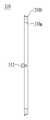
- FIG. 11is a view showing an embodiment of a substrate holder
- FIG. 12is a view showing a portion of a dome portion including the substrate holder of one embodiment
- FIG. 13is a view showing an embodiment of an angle measuring instrument
- FIG. 14is a view illustrating a portion of a dome portion to which an angle measurer is attached in one embodiment.
- the above (on) or (under) (on) or under)when described as being formed on the "on or under” of each element, the above (on) or (under) (on) or under) includes two elements in which the two elements are in direct contact with each other or one or more other elements are formed indirectly between the two elements.
- the above (on) or (under) (on) or under)when expressed as “on” or “under”, it may include the meaning of the downward direction as well as the upward direction based on one element.
- relational termssuch as “first” and “second”, “upper / upper / up” and “lower / lower / lower”, etc., which are used hereinafter, refer to any physical or logical relationship or order between such entities or elements. May be used only to distinguish one entity or element from another entity or element without necessarily requiring or implying.
- each layeris exaggerated, omitted, or schematically illustrated for convenience and clarity of description. Also, the size of each component does not fully reflect its actual size.
- 1 to 2are diagrams illustrating an embodiment of a light emitting device.
- the light emitting deviceis disposed on the light emitting structure 120 including the first conductive semiconductor layer 122, the active layer 124, and the second conductive semiconductor layer 126, and the first and second conductive semiconductor layers.
- Each of the first and second electrodes 142 and 146may be disposed.
- the light emitting structure 120may have at least one mesa region.
- the mesa regioncorresponds to a region including the upper surface and the side surface of the structure formed by mesa etching.
- the light emitting structuremay include a first mesa, and the first conductive semiconductor layer may include a second mesa.
- the first mesa regionmay include a first conductive semiconductor layer 122, an active layer 124, and a second conductive semiconductor layer 126.
- the second mesa regionmay include only the first conductivity type semiconductor layer 122.
- the first mesamay be disposed on the second mesa.
- the light emitting structure 120may include a first conductive semiconductor layer 122, an active layer 124 on the first conductive semiconductor layer, and a second conductive semiconductor layer 126 disposed on the active layer.
- the first conductive semiconductor layer 122may be formed of a compound semiconductor such as a III-V group or a II-VI group, and may be doped with the first conductive dopant.
- the first conductive semiconductor layer 122is a semiconductor material having Al x In y Ga (1-xy) N (0 ⁇ x ⁇ 1, 0 ⁇ y ⁇ 1, 0 ⁇ x + y ⁇ 1), AlGaN. , GaN, InAlGaN, AlGaAs, GaP, GaAs, GaAsP, AlGaInP may be formed of any one or more.
- the first conductivity type dopantmay include an n type dopant such as Si, Ge, Sn, Se, Te, or the like.
- the first conductivity type semiconductor layer 122may be formed as a single layer or a multilayer, but is not limited thereto.
- the active layer 124may be disposed on the first conductivity type semiconductor layer 122.
- the active layer 124is disposed between the first conductivity type semiconductor layer 122 and the second conductivity type semiconductor layer 126, and has a single well structure, a multi well structure, a single quantum well structure, and a multi quantum well.
- a multi-quantum well (MQW) structure, a quantum dot structure or a quantum line structuremay be included.
- the active layer 124is formed of a well layer and a barrier layer, for example AlGaN / AlGaN, InGaN / GaN, InGaN / InGaN, AlGaN / GaN, InAlGaN / GaN, GaAs (InGaAs) using a compound semiconductor material of group III-V elements.
- a barrier layerfor example AlGaN / AlGaN, InGaN / GaN, InGaN / InGaN, AlGaN / GaN, InAlGaN / GaN, GaAs (InGaAs) using a compound semiconductor material of group III-V elements.
- / AlGaAs, GaP (InGaP) / AlGaPmay be formed of any one or more pair structure, but is not limited thereto.
- the well layermay be formed of a material having an energy band gap smaller than the energy band gap of the barrier layer.
- the second conductivity-type semiconductor layer 126may be formed of a semiconductor compound on the surface of the active layer 124.
- the second conductive semiconductor layer 126may be formed of a compound semiconductor such as a group III-V group or a group II-VI, and may be doped with a second conductive dopant.
- the second conductivity-type semiconductor layer 126is, for example, a semiconductor material having a compositional formula of In x Al y Ga 1-xy N (0 ⁇ x ⁇ 1, 0 ⁇ y ⁇ 1, 0 ⁇ x + y ⁇ 1), AlGaN , GaN AlInN, AlGaAs, GaP, GaAs, GaAsP, AlGaInP may be formed of one or more, for example, the second conductivity-type semiconductor layer 126 may be made of Al x Ga (1-x) N.
- the second conductive dopantmay be a p-type dopant such as Mg, Zn, Ca, Sr, or Ba.
- the second conductivity-type semiconductor layer 126may be formed as a single layer or a multilayer, but is not limited thereto.
- the conductive layer 130may be further disposed on the second conductive semiconductor layer 126.
- the conductive layer 130may improve electrical characteristics of the second conductive semiconductor layer 126 and may improve electrical contact with the second electrode 146.
- the conductive layer 130may have a plurality of layers or patterns, and the conductive layer 130 may be formed of a transparent electrode layer having transparency.
- the conductive layer 130may include, for example, indium tin oxide (ITO), indium zinc oxide (IZO), indium zinc tin oxide (IZTO), indium aluminum zinc oxide (IZAZO), indium gallium zinc oxide (IGZO), or IGTO (IGTO).
- ITOindium tin oxide
- IZOindium zinc oxide
- IZTOindium zinc tin oxide
- IZAZOindium aluminum zinc oxide
- IGZOindium gallium zinc oxide
- IGTOIGTO
- Indium Gallium Tin OxideAZO (Aluminum Zinc Oxide), ATO (Antimony Tin Oxide), GZO (Gallium Zinc Oxide), IZON (IZO Nitride), AGZO (Al-Ga ZnO), IGZO (In-Ga ZnO), ZnO (Zinc Oxide), IrOx (Iridium Oxide), RuOx (Ruthenium Oxide), NiO (Nickel Oxide), RuOx / ITO, Ni / IrOx / Au (Gold) may be formed, but is limited to such materials It doesn't work.
- the first electrode 142 and the second electrode 146may be disposed on the first conductive semiconductor layer 122 and the second conductive semiconductor layer 126, respectively.
- the first electrode 142 and the second electrode 146are conductive materials such as indium (In), cobalt (Co), silicon (Si), germanium (Ge), gold (Au), palladium (Pd), Platinum (Pt), Ruthenium (Ru), Rhenium (Re), Magnesium (Mg), Zinc (Zn), Hafnium (Hf), Tantalum (Ta), Rhodium (Rh), Iridium (Ir), Tungsten (W), Metal selected from titanium (Ti), silver (Ag), chromium (Cr), molybdenum (Mo), niobium (Nb), aluminum (Al), nickel (Ni), copper (Cu) and titanium tungsten alloy (WTi) Alternatively, the alloy may be formed as a single layer or a multilayer, but is not limited thereto.
- the alloymay be formed as a single layer or a multilayer, but is not limited thereto.
- the first electrode 142may be disposed in a portion of the second mesa region (Second mesa). That is, the first electrode 142 may be disposed in a portion of the first conductive semiconductor layer 122 exposed by mesa etching.
- the first electrode 142may be a top surface of the first conductivity-type semiconductor layer 122, that is, a portion of the top surface of the second mesa region and the side surface of the second mesa region, and the second surface of the second mesa region. It may be formed extending from the edge of the mesa region.
- the first electrode 142may be formed using the electron beam deposition apparatus of an embodiment described later. That is, the metal layer of the first electrode 142 may be formed in the embodiment of the electron beam deposition apparatus having a variable jig.
- the first electrodeincludes a first region disposed in a partial region on the second mesa region, a second region disposed on the side of the second mesa region, and a third region disposed extending from an edge of the side surface of the second mesa region.
- the thickness ratio of the first region to the third region of the first electrodemay be as follows.
- d1may be a thickness of the first region
- d2may be a thickness of the second region
- d3may be a thickness of the third region.
- the thicknesses d1 and d3 of the first region and the third region of the first electrode layermay be about 1 ⁇ m, and the thickness d2 of the second region may be about 0.9 ⁇ m to about 1.1 ⁇ m.
- a substrate including a deposition surfacemay be formed so that the evaporated metal material may easily reach the stepped portion of the light emitting device formed by the second mesa region. Since it can arrange
- the thickness of the first electrode layermay be uniform in a portion formed extending from the upper surface and side surfaces of the second mesa region and the edge of the side surface.
- the first electrode layermay have a uniform electrode layer thickness when the variable jig is fixed to have an inclination angle of 30 degrees to 45 degrees with respect to the fixed jig in an embodiment of the electron beam deposition apparatus described below.
- the first electrode 142may include an ohmic layer, a reflective layer, and a bonding layer.
- the ohmic layer of the first electrodemay include chromium (Cr) or silver (Ag)
- the reflective layermay include platinum (Pt) and gold (Au), nickel (Ni) and gold (Au), aluminum (Al) and platinum.
- Pt and gold (Au) and aluminum (Al) and nickel (Ni) and gold (Au)may be a structure formed of any one or an alloy thereof, the bonding layer may comprise titanium (Ti). have.
- the ohmic layer of the first electrode 142may facilitate coupling of the first conductive semiconductor layer 122 and the reflective layer, and the coupling layer may be formed for coupling the reflective layer and the insulating layer 150.
- the first electrode 142may be disposed such that a first surface of the first electrode contacts the insulating layer 150 to be described later, and a part of the second surface facing the first surface is exposed to the outside.
- the second electrode 146may be disposed on the second conductivity type semiconductor layer 126.
- the second electrode 146may be disposed on the conductive layer 130.
- the inclination angle of the variable jigmay be fixed to the fixed jig at an angle smaller than 30 degrees.
- the inclination angle of the variable jig in the electron beam deposition apparatus of the embodimentmay be adjusted according to the shape of the metal layer to be deposited.
- the second electrode 146may include an ohmic layer and a reflective layer.
- the ohmic layer of the second electrodemay be made of chromium, silver, or titanium, and the ohmic layer may facilitate coupling of the conductive layer and the reflective layer.
- the reflective layer of the second electrodemay include platinum (Pt), gold (Au), nickel (Ni), gold (Au), aluminum (Al), platinum (Pt), gold (Au), aluminum (Al), nickel ( Ni) and gold (Au) may be any one or an alloy thereof.
- the insulating layer 150may be disposed on the exposed light emitting structure 120 between the first electrode 142 and the second electrode 146.
- the insulating layer 150may be disposed on the exposed surface of the light emitting structure 120 and the first electrode 142.
- the insulating layer 150is disposed on the first mesa region and the second mesa region of the light emitting structure 120, and the second conductive semiconductor layer 126 on the first mesa region is exposed.
- the open areamay be included if possible.
- the second conductive semiconductor layer 126 and the insulating layer 150may be formed outside the region in which the second conductive semiconductor layer 126 or the conductive layer 130 is opened. At least a portion of the second electrode 146 may be overlapped.
- the second electrode 146may be disposed in the open area.
- the second electrode 146may contact the second conductivity type semiconductor layer 126.
- the insulating layer 150may be formed of an insulating material to prevent electrical contact between the first conductive semiconductor layer 122 and the second conductive semiconductor layer 126.
- the insulating layer 150may be formed of a material such as SiO 2 , Si 3 N 4 , polyimide, or the like.
- the insulating layer 150may be formed of a material having a high reflectance in order to increase the efficiency of light emitted from the light emitting structure, for example, may have a DBR structure.
- a side surface of the second mesa regionmay be inclined with respect to the bottom surface of the first conductivity type semiconductor layer 122.
- the inclination angle ⁇ 2 formed at the side surface of the second mesa region with the bottom surface of the first conductive semiconductor layermay be greater than 50 degrees and smaller than 90 degrees.
- the inclination angle ⁇ 2may be 70 degrees to 80 degrees.
- the height of the first conductive semiconductor layer constituting the second mesa regionthat is, the height t1 from the bottom surface of the first conductive semiconductor layer to the upper surface of the second mesa region may be about 2 ⁇ m.
- the side surface of the first mesais shown to be close to the vertical, but the embodiment is not limited thereto, and the side surface of the first mesa may be inclined at an angle with respect to the bottom surface of the light emitting device. It may be disposed obliquely.
- the side surface of the first mesamay be inclined with respect to the upper surface of the second mesa region.
- the inclination angle ⁇ 3 of which the side surface of the first mesa region is the upper surface of the second mesa regionmay be 70 degrees to 90 degrees.
- the inclination angle of the side surface of the first mesa region with the top surface of the second mesa regionmay be the same as the inclination angle of the side surface of the first mesa region with the bottom surface of the first conductive semiconductor layer.
- the inclination angle of the side surface of the second mesa region with the bottom surface of the first conductivity-type semiconductor layeris determined at the inclination angle ⁇ 2 of the portion where the first electrode is disposed and at the portion where the first electrode is not disposed.
- the inclination angles ⁇ 4may be equal to each other.
- the inclination angles ⁇ 2 and ⁇ 4 of the side surfaces of the second mesa region that form the bottom surface of the first conductive semiconductor layermay be 70 degrees to 80 degrees.
- the second mesa regionis formed by the dry etching process, it may not be easy to form the inclination angle of the side surface smaller than 70 degrees, and when the inclination angle formed by the side surface is smaller than 70 degrees, the first slope is gentle.
- the electrode 142may be uniformly deposited, a problem may arise in that the cost is increased by increasing the deposition area of the first metal.
- the step coverage of the first electrode 142is also improved, and the first mesa region including the first electrode 142 is first.
- the deposition thickness of the insulating layer 150 formed on the Mesa and the second mesamay also be uniform.
- ⁇ 4 ⁇ ⁇ 2may be used.
- the inclination angles ⁇ 2 and ⁇ 4 on both sidesmay be 70 to 80 degrees.
- the thickness of the first electrode 142 formed along the side surface of the second mesa regioncan be made uniform by maintaining ⁇ 2 at an inclination angle of ⁇ 4 or less, and thereafter, an insulating layer formed on the first electrode 142.
- the thickness of 150can also be formed uniformly.
- 3A to 3Bshow a perspective view and a plan view of the light emitting device of the embodiment.
- the first electrode 142may be formed along a step of the side surface of the second mesa. That is, the first electrode 142 may be connected to the upper surface of the second mesa, the side of the second mesa, and the edge area extending from the side of the second mesa along the step of the second mesa area.
- the light emitting devicemay be a micro-LED (micro LED), the light emitting device of the embodiment that is a ⁇ LED can be made smaller than the size of a conventional light emitting device.
- the width Wa and the length Wbmay be each within 100 ⁇ m.
- the light emitting device of the embodimenthas a length Wa of 82 ⁇ m and a length of length. (Wb) may have a rectangular shape of 30 ⁇ m.
- the light emitting device of the above-described embodiment or the light emitting device array in which a plurality of light emitting devices of the embodiment are arranged and arrangedmay be used in an apparatus requiring precision due to the miniaturized size, and the first electrode may be formed as a uniform layer on the second mesa region.
- the productivity of the light emitting devicecan be improved by reducing the defects caused by the step coverage.
- FIG. 4is a diagram illustrating an embodiment of an E-beam evaporator.
- the electron beam deposition apparatus 1000may be a device for forming the first electrode 142 of the light emitting device described above.
- the electron beam deposition apparatus 1000may include a thermal electron emitter 430, a source supply part 440, and a dome part 500, and the dome part 500 may include a plurality of substrate holders 300.
- the thermal electron emitter 430may include a thermal filament that receives a high current to emit electrons.
- the electron beam resulting from supplying current to the thermal filamentmay be guided by a magnetic field formed by the electromagnet and concentrated on the deposition material.
- the path of the electron beam supplied from the thermal electron emitter 430 and having high energymay be changed by a magnetic field induced by the electromagnet, and concentrated and transmitted to the source supply part 440.
- the source supply unit 440may include a deposition material to be formed on a substrate using an electron beam deposition apparatus, and the deposition material may be heated by hot electrons and then evaporated to be deposited on the substrate.
- the source supply 440may include a water cooled hearth 460 for storing the deposition material.
- the evaporation material before evaporationmay be contained in a solid state 444, and the center portion of the source supply 440 may be heated and melted by hot electrons supplied from the hot electron emitter 430. molten state) may be contained in the deposition material 442.
- the molten deposition material 442may be evaporated from the source supply 440 to form a thin film on the substrate.
- the dome part 500 including the substrate holder 300 on which the substrate is mountedmay be spaced apart from the source supply part 440.
- the dome part 500may be disposed above the source supply part 440 to be spaced apart by a height at which the deposition material evaporated from the source supply part 440 may reach.
- the dome part 500may be rotated to uniformly deposit the deposition material on the substrate mounted on the dome part.
- FIG. 4schematically illustrates a cross-sectional view of the electron beam deposition apparatus.
- the dome part 500may have a hat shape that is wider from the top to the bottom.
- the side surface of the dome portionmay have an inclination angle ⁇ 1 with respect to the lower surface of the dome portion.
- the side surface of the dome portionmay have an angle of 10 degrees to 15 degrees with respect to the bottom surface of the dome portion.
- FIG. 5is a view schematically showing an upper surface of the dome part 500.
- FIG. 5may be a plan view of the dome part 500 including the plurality of substrate holders 300 viewed from above.
- the plurality of substrate holders 300may be disposed adjacent to a lower portion of the dome portion.
- the plurality of substrate holders 300may be disposed at regular intervals along the lower circumference of the dome portion.
- FIG. 6illustrates a substrate holder 300 of one embodiment.
- the substrate holder 300may include a fixing jig 310 and a variable jig 330.
- the fixing jig 310 and the variable jig 330 of the substrate holder 300may have a ring shape in which a center portion is drilled to mount the substrate, and the substrate for thin film deposition may be fixed to the variable jig 330. Can be.
- the diameter of the variable jig 330may be smaller than the diameter of the fixed jig 310, for example, the outer diameter of the variable jig 330 is smaller than the inner diameter of the fixed jig 310, so that the annular fixed jig 310 may be formed.
- the variable jig 330may be disposed on the inside thereof.
- Figure 8may be a cross-sectional view of the side of the variable jig.
- variable jig 330may have a ring shape, and at least one screw groove may be formed in the direction of the inner surface 330a from the outer surface 330b of the variable jig.
- At least one screw groove formed on the side of the variable jigmay be disposed to correspond to the screw groove of the fixing jig to be described later, the coupling screw 332 connects the screw groove of the corresponding variable jig and the screw groove of the fixing jig Can be placed through.
- two screw groovesmay be formed on the side of the variable jig, and the two screw grooves may be formed on the circumference of the variable jig to face each other.
- the inner surface 330a of the variable jigmay have a stepped portion A, and the substrate may be disposed to be seated on the stepped portion A.
- the deposition surface a in which the thin film layer is formed on the substrate Smay be disposed to face the inner surface 330a having the stepped portion A.
- FIGS. 9 to 10are views illustrating one embodiment of the fixing jig 310.
- Figure 10is a plan view of the fixing jig, Figure 10 may be a view showing a side of the fixing jig.
- a screw groovemay be formed in the direction of the outer surface 310b from the inner surface 310a of the fixing jig so that the coupling screw 332 may be disposed in the screw groove.
- the fixing jig and the variable jigmay be disposed such that at least one screw groove formed on the side of the fixing jig corresponds to the screw groove of the variable jig described above.
- the fixing part 312 for fixing the coupling screw disposed through the screw groovemay be disposed on the fixing jig.
- the fixing part 312may contact the coupling screw 332 through a through hole formed in the upper surface of the fixing jig 310. Meanwhile, the inside of the through hole formed on the fixing part 312 and the fixing jig may have a screw groove.
- the fixing part 312may protrude from the fixing jig 310.
- FIG. 11is a top view of a substrate holder of one embodiment.
- FIG. 11may be a diagram illustrating an embodiment of a substrate holder including a fixing jig and a variable jig.
- At least one screw groovemay be included in each of the side of the fixing jig 310 and the side of the variable jig 330.
- the fixing jig and the variable jigmay be disposed such that the screw grooves formed in the fixing jig 310 and the variable jig 330 correspond to each other, and the coupling screw 332 connects the two jig through each screw groove. Can be.
- the substratemay be mounted on the variable jig 330, and at least one fixing pin 336 may be disposed on one side of the variable jig so that the mounted substrate is not separated to one side.
- One side of the fixing pin 336is fixed to the reference pin 334 disposed on the variable jig 330.
- variable jig 330is coupled to the fixed jig 310 at at least one or more points, and the variable jig may be fixed to have an inclination angle with respect to the fixed jig.
- variable jig 330may be fixedly coupled to the fixed jig 310 at two points on the circumference facing each other, and the annular variable jig and the fixed jig may be on the same plane. Without being arranged, the variable jig 330 and the fixed jig 310 may be fixedly arranged to have an angle between them.
- FIG. 12is a view showing a portion of one of the substrate holder 300 of the plurality of substrate holders disposed in the dome portion of the embodiment.
- the portion within the rectangular dotted line areamay be a portion of the dome portion including one substrate holder 300 in FIG. 4.
- the fixing jig 310may be a portion fixed to the dome portion of the electron beam deposition apparatus.
- variable jig 330may be fixedly coupled to the fixed jig 310 at at least one point, and the substrate S for thin film deposition may be disposed inside the variable jig 330.
- the substrate S mounted on the substrate holder 300is a surface on which the substrate S is deposited. It may be arranged to face.
- FIG. 13is a diagram illustrating an embodiment of an inclination angle measuring device 600.
- the inclination angle measurer 600may be formed to be detachable from the dome portion of the electron beam deposition apparatus.
- the inclination angle measuring devicemay be used to measure the inclination angle of the variable jig based on the fixing jig, and after the variable jig is fixed to have a predetermined inclination angle, the inclination angle measuring device may be detached from the dome part.
- the inclination angle measuring devicemay be detached from the dome portion.
- the tilt angle measuring unit 600may be a scale 620 for angle measurement on the plastic substrate 610.
- the tilt angle measuring devicemay be made of a transparent plastic material, and specifically, acrylic or polycarbonate may be used.
- FIG 14is a view illustrating a part of the dome unit in which the inclination angle measuring unit 600 is attached.
- variable jig 330may be fixed to have an inclination angle ⁇ s with respect to the fixing jig 310 in a state where the inclination angle measuring unit 600 is mounted.
- variable jigmay be rotated based on the portion coupled to the fixed jig, and the variable jig may be adjusted to have an inclination angle of 0 degrees to 90 degrees based on the fixed jig.
- variable jig 330may be fixed to have an inclination angle of 30 degrees to 45 degrees with respect to the fixing jig 310.
- the inclination angle of the variable jigis maintained at 30 degrees to 45 degrees, step coverage of the thin film layer deposited on the deposition substrate having the stepped pattern may be improved.
- the arrangement angle of the variable jigcan be freely adjusted, the arrangement of the variable jig according to the type of deposition material supplied from the source supply unit or the thickness and pattern of the deposition layer to be formed on the substrate during the deposition process.
- the anglecan vary.
- the light emitting device of the above-described embodimentmay be included in a wearable device.
- the light emitting device array including the light emitting device of the embodiment or the light emitting device of the embodimentmay be included in the smart watch.
- the smart watchmay perform pairing with an external digital device
- the external digital devicemay be a digital device capable of communicating with the smart watch, and may include, for example, a smartphone, a notebook computer, an IPTV (Internet Protocol Television), and the like. have.
- a light emitting device arrayin which the light emitting device of the above-described embodiment or the plurality of light emitting devices of the above-described embodiment is aligned and arranged on a flexible printed circuit board (FPCB) may be used.
- FPCBflexible printed circuit board
- the smart watch including the light emitting device of the embodimentmay be worn on the wrist due to the size of the miniaturized light emitting device and the flexibility of the FPCB, and fine pixels may be realized due to the small size of the light emitting device.
- a light guide plate, a prism sheet, a diffusion sheet, and the like, which are optical members,may be disposed on an optical path of the light emitting device.
- the light emitting device, the substrate, and the optical membermay function as a backlight unit.
- the display devicemay include a display device, an indicator device, and a lighting device including the light emitting device according to the embodiment.
- the display devicemay include a bottom cover, a reflector disposed on the bottom cover, a light emitting element emitting light, a light guide plate disposed in front of the reflector, and guiding light emitted from the light emitting element to the front, and disposed in front of the light guide plate.
- An optical sheet including prism sheets to be formed, a display panel disposed in front of the optical sheet, an image signal output circuit connected to the display panel and supplying an image signal to the display panel, and a color filter disposed in front of the display panel.can do.
- the bottom cover, the reflector, the light emitting element array, the light guide plate, and the optical sheetmay form a backlight unit.
- the lighting apparatusmay include a light source module including a substrate and a light emitting device according to an embodiment, a heating element for dissipating heat from the light source module, and a power supply unit configured to process or convert an electrical signal provided from the outside and provide the light source module to the light source module.
- a light source moduleincluding a substrate and a light emitting device according to an embodiment, a heating element for dissipating heat from the light source module, and a power supply unit configured to process or convert an electrical signal provided from the outside and provide the light source module to the light source module.
- the lighting devicemay include a lamp, a head lamp, or a street lamp.
- the size of the devicecan be reduced and the design constraint can be reduced due to the characteristics of the flexible light emitting device array.
- the electron beam deposition apparatus of the embodimentcan freely adjust the placement angle of the substrate fixed to the substrate holder including the variable jig, there is industrial applicability.
Landscapes
- Engineering & Computer Science (AREA)
- Computer Hardware Design (AREA)
- Microelectronics & Electronic Packaging (AREA)
- Power Engineering (AREA)
- Physics & Mathematics (AREA)
- Condensed Matter Physics & Semiconductors (AREA)
- General Physics & Mathematics (AREA)
- Manufacturing & Machinery (AREA)
- Led Devices (AREA)
- Physical Vapour Deposition (AREA)
- Physical Deposition Of Substances That Are Components Of Semiconductor Devices (AREA)
- Container, Conveyance, Adherence, Positioning, Of Wafer (AREA)
Abstract
Description
Translated fromKorean실시예는 발광 소자 및 발광 소자의 전극층을 형성하는 전자 빔 증착 장치에 관한 것이다.Embodiments relate to an electron beam deposition apparatus for forming a light emitting element and an electrode layer of the light emitting element.
GaN, AlGaN 등의 Ⅲ-Ⅴ 족 화합물 반도체는 넓고 조정이 용이한 밴드 갭 에너지를 가지는 등의 많은 장점으로 인해 광 전자 공학 분야(optoelectronics)와 전자 소자 등에 널리 사용된다.Group III-V compound semiconductors such as GaN and AlGaN are widely used in optoelectronics and electronic devices due to many advantages such as wide and easy to adjust band gap energy.
특히, 반도체의 Ⅲ-Ⅴ족 또는 Ⅱ-Ⅵ족 화합물 반도체 물질을 이용한 발광 다이오드(Light Emitting Diode)나 레이저 다이오드와 같은 발광소자는 박막 성장 기술 및 소자 재료의 개발로 적색, 녹색, 청색 및 자외선 등 다양한 색을 구현할 수 있으며, 형광 물질을 이용하거나 색을 조합함으로써 효율이 좋은 백색 광선도 구현이 가능하며, 형광등, 백열등 등 기존의 광원에 비해 저 소비전력, 반영구적인 수명, 빠른 응답속도, 안전성, 환경친화성의 장점을 가진다.In particular, light emitting diodes such as light emitting diodes or laser diodes using the III-V or II-VI compound semiconductor materials of semiconductors have been developed using thin film growth technology and device materials, such as red, green, blue and ultraviolet light. Various colors can be realized, and efficient white light can be realized by using fluorescent materials or by combining colors.Low power consumption, semi-permanent life, fast response speed, safety, It has the advantages of environmental friendliness.
따라서, 광 통신 수단의 송신 모듈, LCD(Liquid Crystal Display) 표시 장치의 백라이트를 구성하는 냉음극관(CCFL: Cold Cathode Fluorescence Lamp)을 대체하는 발광 다이오드 백라이트, 형광등이나 백열 전구를 대체할 수 있는 백색 발광 다이오드 조명 장치, 자동차 헤드 라이트 및 신호등에까지 응용이 확대되고 있다.Therefore, a white light emitting device that can replace a fluorescent light bulb or an incandescent bulb that replaces a Cold Cathode Fluorescence Lamp (CCFL) constituting a backlight of a transmission module of an optical communication means and a liquid crystal display (LCD) display device. Applications are expanding to diode lighting devices, automotive headlights and traffic lights.
또한, 최근에는 휴대용 기기 등의 광원 또는 조명 장치로의 응용이 증가하면서 광 특성이 우수하면서도 크기가 소형인 발광 다이오드의 개발이 이루어지고 있다.In addition, in recent years, as the application to a light source or a lighting device such as a portable device is increasing, development of a light emitting diode having excellent optical characteristics and small size has been made.
소형 발광 다이오드를 구현하기 위하여 발광 구조물의 단면적을 작게 하여 픽셀을 이루게 하려는 시도가 있으나, 각각의 발광 구조물의 두께가 너무 커서 단위 초박형의 단위 픽셀을 구현하기 어렵다.In order to realize a small light emitting diode, attempts have been made to form pixels by reducing the cross-sectional area of the light emitting structure. However, the thickness of each light emitting structure is so large that it is difficult to implement a unit ultra thin unit pixel.
즉, 상술한 발광 다이오드의 발광 구조물은 사파이어 등의 기판 위에서 성장되는데, 발광 구조물의 성장 후에 기판이 그대로 잔존하는 수평형 발광소자, 발광 구조물의 일측에 금속 지지물(metal support)을 결합하고 기판을 제거하는 수직형 발광소자 등의 경우 기판이나 금속 지지물의 두께가 커서 초박형의 픽셀을 이루기 어렵다.That is, the light emitting structure of the above-described light emitting diode is grown on a substrate such as sapphire, the horizontal light emitting device in which the substrate remains as it is after the growth of the light emitting structure, a metal support is coupled to one side of the light emitting structure and the substrate is removed In the case of the vertical light emitting device, the thickness of the substrate or the metal support is large, making it difficult to form an ultra-thin pixel.
또한, 초박형 픽셀에 사용되는 소형 발광 소자의 경우 단차를 가지는 부분에서 반도체층 또는 금속층의 스텝 커버리지(Step coverage)가 나쁠 경우 발광 소자의 성능이 저하되는 문제가 발생할 수 있다.In addition, in the case of a small light emitting device used in an ultra-thin pixel, when the step coverage of the semiconductor layer or the metal layer is poor in a portion having a step, the performance of the light emitting device may be deteriorated.
따라서, 실시예는 전자 빔 증착 장치에서 기판 홀더의 구조를 개선하여 금속층의 증착 품질이 개선된 초박형의 발광 소자를 구현하고자 한다.Therefore, the embodiment is intended to implement an ultra-thin light emitting device in which the deposition quality of the metal layer is improved by improving the structure of the substrate holder in the electron beam deposition apparatus.
실시예가 이루고자 하는 기술적 과제는 이상에서 언급한 기술적 과제로 제한되지 않으며 언급되지 않은 또 다른 기술적 과제들은 아래의 기재로부터 실시예가 속하는 기술분야에서 통상의 지식을 가진자에게 명확하게 이해될 수 있을 것이다.Embodiments of the present invention are not limited to the above-mentioned technical problems, and other technical problems not mentioned above may be clearly understood by those skilled in the art to which the embodiments belong.
실시예는 제1 도전형 반도체층, 활성층 및 제2 도전형 반도체층을 포함하는 발광 구조물; 및 상기 제1 및 제2 도전형 반도체층 상에 각각 배치된 제1 및 제2 전극; 을 포함하고, 상기 발광 구조물은 제1 메사 영역을 포함하고, 상기 제1 도전형 반도체층은 제2 메사 영역을 포함하며, 상기 제1 전극은 상기 제2 메사 영역 상부면의 일부 영역인 제1 영역; 상기 제2 메사 영역의 측면인 제2 영역; 및 상기 제2 메사 영역의 상기 측면의 가장자리에서 연장되어 배치된 제3 영역; 을 포함하며, 상기 제1 영역, 상기 제2 영역 및 상기 제3 영역의 두께 비는 아래와 같은 발광 소자를 제공한다.Embodiments may include a light emitting structure including a first conductive semiconductor layer, an active layer, and a second conductive semiconductor layer; First and second electrodes disposed on the first and second conductivity-type semiconductor layers, respectively; The light emitting structure may include a first mesa region, the first conductive semiconductor layer may include a second mesa region, and the first electrode may be a partial region of an upper surface of the second mesa region. domain; A second region that is a side surface of the second mesa region; And a third region extending from an edge of the side surface of the second mesa region. The thickness ratio of the first region, the second region and the third region provides a light emitting device as follows.
d1 : d2 : d3 = 1: 0.9~1.1 : 1d1: d2: d3 = 1: 0.9 to 1.1: 1
(여기서, d1은 제1 영역의 두께, d2는 제2 영역의 두께, d3는 제3 영역의 두께에 해당한다.)(Where d1 corresponds to the thickness of the first region, d2 corresponds to the thickness of the second region, and d3 corresponds to the thickness of the third region.)
다른 실시예는 상기 제1 전극을 형성하며, 열 전자 방출부; 상기 열 전자 방출부에서 공급된 열 전자에 의하여 증발되는 증착 물질을 포함한 소스 공급부; 및 상기 소스 공급부 상에 이격되어 배치되는 돔부; 를 포함하며, 상기 돔부는 복수의 기판 홀더를 포함하고, 상기 복수의 기판 홀더는 경사각이 조절되는 가변 지그를 포함하는 전자 빔 증착 장치를 제공한다.Another embodiment forms the first electrode, the thermal electron emission portion; A source supply including a deposition material evaporated by the hot electrons supplied by the hot electron emitter; And a dome part spaced apart from the source supply part; The dome unit includes a plurality of substrate holders, and the plurality of substrate holders provide an electron beam deposition apparatus including a variable jig in which an inclination angle is adjusted.
실시예의 전자 빔 증착 장치는 가변 지그를 포함하여 기판 홀더에 고정되는 기판의 배치 각도를 자유롭게 조절할 수 있으며, 이러한 전자 빔 증착 장치를 이용할 경우 금속층 증착 시 공급되는 소스에 대하여 기판을 경사지게 기울여 배치함으로써 발광 소자에서 단차를 갖는 층에서 스텝 커버리지를 개선할 수 있다.The electron beam deposition apparatus of the embodiment can freely adjust the placement angle of the substrate fixed to the substrate holder including a variable jig, and when using such an electron beam deposition apparatus, the substrate is inclined to be inclined with respect to the source supplied when the metal layer is deposited to emit light. Step coverage can be improved in layers with steps in the device.
도 1 내지 도 2는 발광 소자의 일 실시예를 나타낸 도면이고,1 to 2 is a view showing an embodiment of a light emitting device,
도 3a는 일 실시예의 발광 소자에 대한 사시도이고,3A is a perspective view of a light emitting device according to one embodiment;
도 3b는 일 실시예의 발광 소자에 대한 평면도이고,3B is a plan view of a light emitting device according to one embodiment;
도 4는 전자 빔 증착 장치의 일 실시예를 나타낸 도면이고,4 is a view showing an embodiment of an electron beam deposition apparatus,
도 5는 돔부의 상부면을 나타낸 도면이고,5 is a view showing an upper surface of the dome portion;
도 6은 기판 홀더부의 일 실시예를 나타낸 도면이고,6 is a view showing an embodiment of a substrate holder portion,
도 7 내지 도 8은 가변 지그의 일 실시예를 나타낸 도면이고,7 to 8 is a view showing an embodiment of a variable jig,
도 9 내지 도 10은 고정 지그의 일 실시예를 나타낸 도면이고,9 to 10 is a view showing an embodiment of a fixing jig,
도 11은 기판 홀더의 일 실시예를 나타낸 도면이고,11 is a view showing an embodiment of a substrate holder,
도 12는 일 실시예의 기판 홀더를 포함한 돔부의 일 부분을 나타낸 도면이고,12 is a view showing a portion of a dome portion including the substrate holder of one embodiment,
도 13은 각도 측정기의 일 실시예를 나타낸 도면이고13 is a view showing an embodiment of an angle measuring instrument;
도 14는 일 실시예의 각도 측정기가 부착된 돔부의 일 부분을 나타낸 도면이다.14 is a view illustrating a portion of a dome portion to which an angle measurer is attached in one embodiment.
이하 상기의 목적을 구체적으로 실현할 수 있는 본 발명의 실시예를 첨부한 도면을 참조하여 설명한다.Hereinafter, with reference to the accompanying drawings an embodiment of the present invention that can specifically realize the above object.
본 발명에 따른 실시예의 설명에 있어서, 각 element의 “상(위) 또는 하(아래)(on or under)”에 형성되는 것으로 기재되는 경우에 있어, 상(위) 또는 하(아래)(on or under)는 두 개의 element가 서로 직접(directly)접촉되거나 하나 이상의 다른 element가 상기 두 element사이에 배치되어(indirectly) 형성되는 것을 모두 포함한다. 또한 “상(위) 또는 하(아래)(on or under)”로 표현되는 경우 하나의 element를 기준으로 위쪽 방향뿐만 아니라 아래쪽 방향의 의미도 포함할 수 있다.In the description of the embodiment according to the present invention, when described as being formed on the "on or under" of each element, the above (on) or (under) (on) or under) includes two elements in which the two elements are in direct contact with each other or one or more other elements are formed indirectly between the two elements. In addition, when expressed as “on” or “under”, it may include the meaning of the downward direction as well as the upward direction based on one element.
또한, 이하에서 이용되는 “제1” 및 “제2”, “상/상부/위” 및 “하/하부/아래” 등과 같은 관계적 용어들은 그런 실체 또는 요소들 간의 어떠한 물리적 또는 논리적 관계 또는 순서를 반드시 요구하거나 내포하지는 않으면서, 어느 한 실체 또는 요소를 다른 실체 또는 요소와 구별하기 위해서만 이용될 수도 있다.In addition, the relational terms such as “first” and “second”, “upper / upper / up” and “lower / lower / lower”, etc., which are used hereinafter, refer to any physical or logical relationship or order between such entities or elements. May be used only to distinguish one entity or element from another entity or element without necessarily requiring or implying.
도면에서 각층의 두께나 크기는 설명의 편의 및 명확성을 위하여 과장되거나 생략되거나 또는 개략적으로 도시되었다. 또한 각 구성요소의 크기는 실제 크기를 전적으로 반영하는 것은 아니다.In the drawings, the thickness or size of each layer is exaggerated, omitted, or schematically illustrated for convenience and clarity of description. Also, the size of each component does not fully reflect its actual size.
도 1 내지 도 2는 발광 소자의 일 실시예를 나타낸 도면이다.1 to 2 are diagrams illustrating an embodiment of a light emitting device.
일 실시예의 발광 소자는 제1 도전형 반도체층(122)과 활성층(124)과 제2 도전형 반도체층(126)을 포함하는 발광 구조물(120) 및 제1 및 제2 도전형 반도체층 상에 각각 배치된 제1 전극(142)과 제2 전극(146)을 포함할 수 있다.In one embodiment, the light emitting device is disposed on the
도 1 내지 도 2를 참조하면, 발광 구조물(120)은 적어도 하나의 메사(Mesa) 영역을 가질 수 있다. 여기서, 메사 영역은 메사 식각에 의하여 형성된 구조물의 상부면과 측면을 포함하는 영역에 해당한다.1 to 2, the
발광 구조물은 제1 메사 영역(First mesa)을 포함하고, 제1 도전형 반도체층은 제2 메사 영역(Second mesa)을 포함할 수 있다.The light emitting structure may include a first mesa, and the first conductive semiconductor layer may include a second mesa.
예를 들어, 도 1 내지 도 2에서 제1 메사(First Mesa) 영역은 제1 도전형 반도체층(122), 활성층(124) 및 제2 도전형 반도체층(126)을 포함하는 것 일 수 있으며, 제2 메사(Second Mesa) 영역은 제1 도전형 반도체층(122) 만을 포함하는 것일 수 있다. 또한, 제1 메사 영역(First mesa)은 제2 메사 영역(Second mesa) 상에 배치될 수 있다.For example, in FIGS. 1 and 2, the first mesa region may include a first
발광 구조물(120)은 제1 도전형 반도체층(122), 제1 도전형 반도체층 상의 활성층(124) 및 활성층 상에 배치되는 제2 도전형 반도체층(126)을 포함할 수 있다.The
제1 도전형 반도체층(122)은 Ⅲ-Ⅴ족, Ⅱ-Ⅵ족 등의 화합물 반도체로 구현될 수 있으며, 제1 도전형 도펀트가 도핑될 수 있다. 제1 도전형 반도체층(122)은 AlxInyGa(1-x-y)N (0≤x≤1, 0≤y≤1, 0≤x+y≤1)의 조성식을 갖는 반도체 물질, AlGaN, GaN, InAlGaN, AlGaAs, GaP, GaAs, GaAsP, AlGaInP 중 어느 하나 이상으로 형성될 수 있다.The first
제1 도전형 반도체층(122)이 n형 반도체층인 경우, 제1 도전형 도펀트는 Si, Ge, Sn, Se, Te 등과 같은 n형 도펀트를 포함할 수 있다. 제1 도전형 반도체층(122)은 단층 또는 다층으로 형성될 수 있으며, 이에 대해 한정하지 않는다.When the first conductivity
제1 도전형 반도체층(122) 상에는 활성층(124)이 배치될 수 있다.The
활성층(124)은 제1 도전형 반도체층(122)과 제2 도전형 반도체층(126) 사이에 배치되며, 단일 우물 구조(Double Hetero Structure), 다중 우물 구조, 단일 양자 우물 구조, 다중 양자 우물(MQW:Multi Quantum Well) 구조, 양자점 구조 또는 양자선 구조 중 어느 하나를 포함할 수 있다.The
활성층(124)은 Ⅲ-Ⅴ족 원소의 화합물 반도체 재료를 이용하여 우물층과 장벽층, 예를 들면 AlGaN/AlGaN, InGaN/GaN, InGaN/InGaN, AlGaN/GaN, InAlGaN/GaN, GaAs(InGaAs)/AlGaAs, GaP(InGaP)/AlGaP 중 어느 하나 이상의 페어 구조로 형성될 수 있으나 이에 한정되지는 않는다. 우물층은 장벽층의 에너지 밴드 갭보다 작은 에너지 밴드 갭을 갖는 물질로 형성될 수 있다.The
제2 도전형 반도체층(126)은 활성층(124)의 표면에 반도체 화합물로 형성될 수 있다. 제2 도전형 반도체층(126)은 Ⅲ-Ⅴ족, Ⅱ-Ⅵ족 등의 화합물 반도체로 구현될 수 있으며, 제2 도전형 도펀트가 도핑될 수 있다. 제2 도전형 반도체층(126)은 예컨대, InxAlyGa1-x-yN (0≤x≤1, 0≤y≤1, 0≤x+y≤1)의 조성식을 갖는 반도체 물질, AlGaN, GaN AlInN, AlGaAs, GaP, GaAs, GaAsP, AlGaInP 중 어느 하나 이상으로 형성될 수 있으며, 예를 들어 제2 도전형 반도체층(126)이 AlxGa(1-x)N으로 이루어질 수 있다.The second conductivity-
제2 도전형 반도체층(126)이 p형 반도체층인 경우, 제2 도전형 도펀트는 Mg, Zn, Ca, Sr, Ba 등과 같은 p형 도펀트일 수 있다. 제2 도전형 반도체층(126)은 단층 또는 다층으로 형성될 수 있으며, 이에 대해 한정하지는 않는다.When the second
제2 도전형 반도체층(126) 상에는 도전층(130)이 더 배치될 수 있다.The
도전층(130)은 제2 도전형 반도체층(126)의 전기적 특성을 향상시키고, 제2 전극(146)과의 전기적 접촉을 개선할 수 있다. 도전층(130)은 복수의 층 또는 패턴을 가지고 형성될 수 있으며 도전층(130)은 투과성을 갖는 투명 전극층으로 형성될 수 있다.The
도전층(130)은 예를 들어, ITO(Indium Tin Oxide), IZO(Indium Zinc Oxide), IZTO(Indium Zinc Tin Oxide), IAZO(Indium Aluminum Zinc Oxide), IGZO(Indium Gallium Zinc Oxide), IGTO(Indium Gallium Tin Oxide), AZO(Aluminum Zinc Oxide), ATO(Antimony Tin Oxide), GZO(Gallium Zinc Oxide), IZON(IZO Nitride), AGZO(Al-Ga ZnO), IGZO(In-Ga ZnO), ZnO(Zinc Oxide), IrOx(Iridium Oxide), RuOx(Ruthenium Oxide), NiO(Nickel Oxide), RuOx/ITO, Ni/IrOx/Au(Gold) 중 적어도 하나를 포함하여 형성될 수 있으나, 이러한 재료에 한정되지 않는다.The
제1 도전형 반도체층(122)과 제2 도전형 반도체층(126) 상에는 각각 제1 전극(142)과 제2 전극(146)이 배치될 수 있다.The
제1 전극(142) 및 제2 전극(146)은 전도성 물질, 예를 들어 인듐(In), 코발트(Co), 규소(Si), 게르마늄(Ge), 금(Au), 팔라듐(Pd), 백금(Pt), 루테늄(Ru), 레늄(Re), 마그네슘(Mg), 아연(Zn), 하프늄(Hf), 탄탈(Ta), 로듐(Rh), 이리듐(Ir), 텅스텐(W), 티타늄(Ti), 은(Ag), 크롬(Cr), 몰리브덴(Mo), 나이오븀(Nb), 알루미늄(Al), 니켈(Ni), 구리(Cu) 및 티타늄 텅스텐 합금(WTi) 중에서 선택된 금속 또는 합금을 이용하여 단층 또는 다층으로 형성될 수 있으나, 이에 한정하지 아니한다.The
제 1전극(142)은 제2 메사 영역(Second mesa) 상의 일부 영역에 배치될 수 있다. 즉, 제1 전극(142)은 메사 식각에 의하여 노출된 제1 도전형 반도체층(122)의 일부 영역에 배치될 수 있다.The
도 1 내지 도 2의 실시예에서 제1 전극(142)은 제1 도전형 반도체층(122)의 상부면, 즉 제2 메사 영역의 상부면 중 일부와 제2 메사 영역의 측면, 그리고 제2 메사 영역의 가장 자리에서 연장되어 형성될 수 있다.1 to 2, the
발광 소자의 일 실시예에서 제1 전극(142)은 후술하는 일 실시예의 전자 빔 증착 장치를 이용하여 형성될 수 있다. 즉, 제1 전극(142)의 금속층은 가변 지그를 갖는 전자 빔 증착 장치의 실시예에서 형성될 수 있다.In an embodiment of the light emitting device, the
제1 전극은 제2 메사 영역 상의 일부 영역에 배치된 제1 영역, 제2 메사 영역의 측면에 배치된 제2 영역과 제2 메사 영역의 측면의 가장자리에서 연장되어 배치된 제3 영역을 포함하며, 제1 전극의 제1 영역 내지 제3 영역의 두께비는 아래와 같을 수 있다.The first electrode includes a first region disposed in a partial region on the second mesa region, a second region disposed on the side of the second mesa region, and a third region disposed extending from an edge of the side surface of the second mesa region. The thickness ratio of the first region to the third region of the first electrode may be as follows.
d1 : d2 : d3 = 1 : 0.9~1.1 : 1d1: d2: d3 = 1: 0.9 ~ 1.1: 1
여기서, d1은 제1 영역의 두께이고, d2는 제2 영역의 두께, d3는 제3 영역의 두께일 수 있다.Here, d1 may be a thickness of the first region, d2 may be a thickness of the second region, and d3 may be a thickness of the third region.
예를 들어, 제1 전극층의 제1 영역과 제3 영역의 두께(d1, d3)는 1㎛ 내외일 수 있으며, 제2 영역의 두께(d2)는 0.9㎛ 내지 1.1㎛일 수 있다.For example, the thicknesses d1 and d3 of the first region and the third region of the first electrode layer may be about 1 μm, and the thickness d2 of the second region may be about 0.9 μm to about 1.1 μm.
후술하는 전자 빔 증착 장치를 이용하여 제1 전극의 금속층을 증착하는 경우, 제2 메사 영역에 의하여 형성된 발광 소자의 단차 부분으로 증발된 증착 금속 물질이 용이하게 도달할 수 있도록 증착면을 포함한 기판을 기울여서 배치할 수 있으므로, 단차를 갖는 제1 전극층의 두께를 전체적으로 균일하게 형성할 수 있다.When the metal layer of the first electrode is deposited using an electron beam deposition apparatus, which will be described later, a substrate including a deposition surface may be formed so that the evaporated metal material may easily reach the stepped portion of the light emitting device formed by the second mesa region. Since it can arrange | position inclined, the thickness of the 1st electrode layer which has a level | step difference can be formed uniformly as a whole.
즉, 제1 전극층의 두께는 제2 메사 영역의 상부면과 측면 및 측면의 가장자리에서 연장되어 형성된 부분에서 균일할 수 있다.That is, the thickness of the first electrode layer may be uniform in a portion formed extending from the upper surface and side surfaces of the second mesa region and the edge of the side surface.
또한, 제1 전극층은 후술하는 전자 빔 증착 장치의 실시예에서 가변 지그가 고정 지그에 대하여 30도 내지 45도의 경사각을 갖도록 고정된 경우에서 스텝 커버리지가 양호하게 나타나 균일한 전극층 두께를 가질 수 있다.In addition, the first electrode layer may have a uniform electrode layer thickness when the variable jig is fixed to have an inclination angle of 30 degrees to 45 degrees with respect to the fixed jig in an embodiment of the electron beam deposition apparatus described below.
제1 전극(142)은, 오믹층, 반사층 및 결합층을 포함할 수 있다. 제1 전극의 오믹층은 크롬(Cr)이나 은(Ag)을 포함할 수 있고, 반사층은 백금(Pt)과 금(Au), 니켈(Ni)과 금(Au), 알루미늄(Al)과 백금(Pt)과 금(Au) 및 알루미늄(Al)과 니켈(Ni)과 금(Au)의 구조 중 어느 하나 또는 이들의 합금으로 형성된 구조일 수 있으며, 결합층은 티타늄(Ti)을 포함할 수 있다.The
제1 전극(142)의 오믹층은 제1 도전형 반도체층(122)과 반사층의 결합을 용이하게 할 수 있으며, 결합층은 반사층과 절연층(150)의 결합을 위하여 형성될 수 있다.The ohmic layer of the
한편, 제1 전극(142)은 제1면이 후술하는 절연층(150)과 접촉하고, 제1면과 마주보는 제2면의 일부가 외부로 노출되어 배치될 수 있다.The
도 1 내지 도 2의 실시예에서, 제2 전극(146)은 제2 도전형 반도체층(126) 상에 배치될 수 있다.1 and 2, the
또한, 제2 도전형 반도체층(126) 상에 도전층(130)을 더 포함하는 경우 제2 전극(146)은 도전층(130) 상에 배치될 수 있다.In addition, when the
한편, 제2 전극(146)이 후술하는 전자 빔 증착 장치에 의하여 형성될 경우, 가변 지그의 경사각은 30도 보다 작은 각도로 고정 지그에 고정될 수 있다.On the other hand, when the
즉, 증착하고자 하는 금속층의 형상에 따라 실시예의 전자 빔 증착 장치에서 가변 지그의 경사각은 조절될 수 있다.That is, the inclination angle of the variable jig in the electron beam deposition apparatus of the embodiment may be adjusted according to the shape of the metal layer to be deposited.
제2 전극(146)은 오믹층과 반사층을 포함할 수 있다.The
제2 전극의 오믹층은 크롬이나 은 또는 티타늄으로 이루어질 수 있고, 오믹층은 도전층과 반사층의 결합을 용이하게 할 수 있다.The ohmic layer of the second electrode may be made of chromium, silver, or titanium, and the ohmic layer may facilitate coupling of the conductive layer and the reflective layer.
또한, 제2 전극의 반사층은 백금(Pt)과 금(Au), 니켈(Ni)과 금(Au), 알루미늄(Al)과 백금(Pt)과 금(Au) 및 알루미늄(Al)과 니켈(Ni)과 금(Au)의 구조 중 어느 하나 또는 이들의 합금일 수 있다.In addition, the reflective layer of the second electrode may include platinum (Pt), gold (Au), nickel (Ni), gold (Au), aluminum (Al), platinum (Pt), gold (Au), aluminum (Al), nickel ( Ni) and gold (Au) may be any one or an alloy thereof.
도 1 내지 도 2의 실시예에서 절연층(150)은 제1 전극(142)과 제2 전극(146) 사이의 노출된 발광 구조물(120) 상에 배치될 수 있다.1 and 2, the insulating
또한, 절연층(150)은 발광 구조물(120)의 노출된 표면 및 제1 전극(142) 상에 배치될 수 있다.In addition, the insulating
절연층(150)은 발광 구조물(120)의 제1 메사 영역(First mesa)과 제2 메사 영역(Second mesa) 상에 배치되되, 제1 메사 영역 상의 제2 도전형 반도체층(126)이 노출되도록 오픈 영역을 포함할 수 있다.The insulating
또한, 제1 메사 영역(First mesa)에서, 제2 도전형 반도체층(126) 또는 도전층(130)이 오픈 된 영역의 외곽에서 제2 도전형 반도체층(126)과 절연층(150)과 제2 전극(146)이 적어도 일부가 중첩되어 배치될 수 있다.In addition, in the first mesa, the second
한편, 오픈 영역에는 제2 전극(146)의 적어도 일부가 배치될 수 있다. 이때, 제2 전극(146)은 제2 도전형 반도체층(126)과 접촉할 수 있다.Meanwhile, at least a portion of the
절연층(150)은 제1 도전형 반도체층(122)과 제2 도전형 반도체층(126)의 전기적인 접촉을 방지하기 위하여 절연성 재료로 형성될 수 있다.The insulating
절연층(150)은 SiO2, Si3N4, 폴리이미드(Polyimide) 등의 재료로 형성될 수 있다.The insulating
또한, 절연층(150)은 발광 구조물에서 방출되는 광의 효율을 높이기 위하여 반사율이 높은 재료로 형성될 수 있으며, 예를 들어 DBR 구조를 가질 수 있다.In addition, the insulating
도 1을 참조하면, 제2 메사 영역(Second Mesa)의 측면은 제1 도전형 반도체층(122)의 바닥면에 대하여 경사지게 배치될 수 있다.Referring to FIG. 1, a side surface of the second mesa region may be inclined with respect to the bottom surface of the first conductivity
예를 들어, 제2 메사 영역의 측면이 제1 도전형 반도체층의 바닥면과 이루는 경사각(θ2)은 50도 보다 크고 90도 보다 작을 수 있다. 구체적으로, 경사각 θ2는 70도 내지 80도일 수 있다.For example, the inclination angle θ2 formed at the side surface of the second mesa region with the bottom surface of the first conductive semiconductor layer may be greater than 50 degrees and smaller than 90 degrees. Specifically, the inclination angle θ2 may be 70 degrees to 80 degrees.
또한, 제2 메사 영역을 이루는 제1 도전형 반도체층의 높이, 즉 제1 도전형 반도체층의 바닥면부터 제2 메사 영역의 상부면까지의 높이(t1)는 2㎛ 내외일 수 있다.In addition, the height of the first conductive semiconductor layer constituting the second mesa region, that is, the height t1 from the bottom surface of the first conductive semiconductor layer to the upper surface of the second mesa region may be about 2 μm.
도 1에서 제1 메사 영역(First Mesa)의 측면은 수직에 가깝게 도시되었으나, 실시예는 이에 한정하지 않으며, 제1 메사 영역(First Mesa)의 측면은 발광 소자의 바닥면에 대하여 일정 각도로 기울어져 경사지게 배치될 수 있다.In FIG. 1, the side surface of the first mesa is shown to be close to the vertical, but the embodiment is not limited thereto, and the side surface of the first mesa may be inclined at an angle with respect to the bottom surface of the light emitting device. It may be disposed obliquely.
도 2를 참고하면, 제1 메사 영역(First Mesa)의 측면은 제2 메사 영역의 상부면에 대하여 경사지게 배치될 수 있다.Referring to FIG. 2, the side surface of the first mesa may be inclined with respect to the upper surface of the second mesa region.
예를 들어, 제1 메사 영역의 측면이 제2 메사 영역의 상부면과 이루는 경사각(θ3)은 70도 내지 90도일 수 있다. 한편, 제1 메사 영역의 측면이 제2 메사 영역의 상부면과 이루는 경사각은 제1 메사 영역의 측면이 제1 도전형 반도체층의 바닥면과 이루는 경사각과 동일할 수 있다.For example, the inclination angle θ3 of which the side surface of the first mesa region is the upper surface of the second mesa region may be 70 degrees to 90 degrees. Meanwhile, the inclination angle of the side surface of the first mesa region with the top surface of the second mesa region may be the same as the inclination angle of the side surface of the first mesa region with the bottom surface of the first conductive semiconductor layer.
또한, 도 2의 실시예에서 제2 메사 영역의 측면이 제1 도전형 반도체층의 바닥면과 이루는 경사각은 제1 전극이 배치된 부분의 경사각(θ2)과 제1 전극이 배치되지 않은 부분에서의 경사각(θ4)은 서로 동일할 수 있다. 예를 들어, 제2 메사 영역의 측면이 제1 도전형 반도체층의 바닥면과 이루는 양 측의 경사각(θ2, θ4)은 70도 내지 80도일 수 있다.In addition, in the embodiment of FIG. 2, the inclination angle of the side surface of the second mesa region with the bottom surface of the first conductivity-type semiconductor layer is determined at the inclination angle θ2 of the portion where the first electrode is disposed and at the portion where the first electrode is not disposed. The inclination angles θ4 may be equal to each other. For example, the inclination angles θ2 and θ4 of the side surfaces of the second mesa region that form the bottom surface of the first conductive semiconductor layer may be 70 degrees to 80 degrees.
제2 메사 영역이 건식 식각 공정에 의하여 형성되는 경우, 측면의 경사각을 70도 보다 작게 형성하는 것이 공정상 용이하지 않을 수 있으며, 또한 측면이 이루는 경사각이 70도 보다 작은 경우, 완만한 경사로 제1 전극(142)이 균일하게 증착될 수 있으나 제1 금속의 증착면적이 늘어남으로써 비용이 증가되는 문제가 발생할 수 있다.When the second mesa region is formed by the dry etching process, it may not be easy to form the inclination angle of the side surface smaller than 70 degrees, and when the inclination angle formed by the side surface is smaller than 70 degrees, the first slope is gentle. Although the
또한, 80도 보다 큰 경사각을 가져서 수직에 가깝게 형성될 경우 제1 전극의 스텝커버리지 불량이 발생하여 단선의 발생 가능성이 커질 수 있다.In addition, when the inclination angle is greater than 80 degrees and is formed close to the vertical, a poor step coverage of the first electrode may occur, thereby increasing the possibility of disconnection.
즉, 제2 메사 영역의 측면 경사각(θ2, θ4)가 70도 내지 80도인 경우 제1 전극(142)의 스텝 커버리지도 개선되며, 또한 제1 전극(142)을 포함하여 제1 메사 영역(First Mesa)과 제2 메사 영역(Second Mesa) 상에 형성되는 절연층(150)의 증착 두께도 균일해질 수 있다.That is, when the side inclination angles θ2 and θ4 of the second mesa region are 70 degrees to 80 degrees, the step coverage of the
한편, 도 2의 실시예에서 제2 메사 영역의 양측의 경사각이 서로 달라지는 경우에 있어서, θ4 ≥ θ2 일 수 있다. 이 경우에도 양측의 경사각(θ2, θ4)은 70도 내지 80도일 수 있다.Meanwhile, when the inclination angles of both sides of the second mesa region are different from each other in the embodiment of FIG. 2, θ4 ≥ θ2 may be used. Also in this case, the inclination angles θ2 and θ4 on both sides may be 70 to 80 degrees.
다만, θ2가 θ4 이하의 경사각으로 유지되도록 하여 제2 메사 영역의 측면을 따라 형성된 제1 전극(142)의 두께를 균일하게 할 수 있고, 이후에 제1 전극(142) 상에 형성되는 절연층(150)의 두께도 균일하게 형성할 수 있다.However, the thickness of the
도 3a 내지 도 3b는 실시예의 발광 소자에 대한 사시도 및 평면도를 나타낸 것이다.3A to 3B show a perspective view and a plan view of the light emitting device of the embodiment.
도 3a를 참조하면, 제1 전극(142)은 제2 메사의 측면의 단차를 따라 형성될 수 있다. 즉, 제1 전극(142)은 제2 메사의 상부면과 제2 메사의 측면 및 제2 메사의 측면에서 연장된 가장자리 영역까지 제2 메사 영역의 단차를 따라 하나로 연결되어 형성될 수 있다.Referring to FIG. 3A, the
또한, 발광 소자(LED)는 μ LED(micro LED)일 수 있으며, μ LED인 실시예의 발광 소자는 통상의 발광 소자의 크기보다 소형으로 제작될 수 있다. 도 3b의 평면도를 참조하면, 발광 소자에서 가로 길이(Wa)와 세로 길이(Wb)가 각각 100 ㎛이내 일 수 있으며, 예를 들어 실시예의 발광 소자는 가로 길이(Wa)가 82㎛이고 세로 길이(Wb)가 30㎛인 직사각형 형태를 가질 수 있다.In addition, the light emitting device (LED) may be a micro-LED (micro LED), the light emitting device of the embodiment that is a μ LED can be made smaller than the size of a conventional light emitting device. Referring to the plan view of FIG. 3B, in the light emitting device, the width Wa and the length Wb may be each within 100 μm. For example, the light emitting device of the embodiment has a length Wa of 82 μm and a length of length. (Wb) may have a rectangular shape of 30 μm.
상술한 실시예의 발광 소자 또는 실시예의 발광 소자를 복수 개 정렬하여 배치한 발광 소자 어레이는 소형화된 크기로 인하여 정밀도를 요하는 장치에 사용될 수 있으며, 제1 전극이 제2 메사 영역 상에서 균일한 층으로 형성되도록 하여 스텝 커버리지에 의한 불량 요소를 감소 시킴으로써 발광 소자의 생산성이 향상될 수 있다.The light emitting device of the above-described embodiment or the light emitting device array in which a plurality of light emitting devices of the embodiment are arranged and arranged may be used in an apparatus requiring precision due to the miniaturized size, and the first electrode may be formed as a uniform layer on the second mesa region. The productivity of the light emitting device can be improved by reducing the defects caused by the step coverage.
도 4는 전자 빔 증착 장치(E-beam evaporator)의 일 실시예를 나타낸 도면이다.4 is a diagram illustrating an embodiment of an E-beam evaporator.
일 실시예의 전자 빔 증착 장치(1000)는 상술한 발광 소자의 제1 전극(142)을 형성하는 장치 일 수 있다.The electron
전자 빔 증착 장치(1000)는 열 전자 방출부(430), 소스 공급부(440) 및 돔부(500)를 포함할 수 있으며, 돔부(500)에는 복수의 기판 홀더(300)를 포함할 수 있다.The electron
열 전자 방출부(430)는 고전류를 공급받아 전자를 방출하는 열 필라멘트(Thermionic filament)를 포함할 수 있다.The
열 필라멘트에 전류를 공급하여 나오는 전자 빔은 전자석에 의하여 형성된 자기장에 의하여 유도되어 증착 재료에 집중될 수 있다.The electron beam resulting from supplying current to the thermal filament may be guided by a magnetic field formed by the electromagnet and concentrated on the deposition material.
즉, 열 전자 방출부(430)에서 공급되며 고 에너지를 갖는 전자 빔은 전자석에 의하여 유도된 자기장에 의하여 경로가 변경될 수 있으며, 소스 공급부(440)에 집중되어 전달될 수 있다.That is, the path of the electron beam supplied from the
소스 공급부(440)는 전자 빔 증착 장치를 이용하여 기판에 형성하고자 하는 증착 물질을 포함할 수 있으며, 증착 물질은 열 전자에 의하여 가열된 후 증발되어 기판에 증착될 수 있다.The
소스 공급부(440)는 증착 재료를 보관하는 수냉 도가니(Water cooled hearth, 460)를 포함할 수 있다.The
수냉 도가니에는 증발되기 전의 증착 재료가 고상(solid state, 444)로 담겨있을 수 있으며, 소스 공급부(440)의 가운데 부분에는 열 전자 방출부(430)에서 공급된 열 전자에 의하여 가열하여 용융된(molten state) 증착 재료(442)로 담겨있을 수 있다.In the water-cooled crucible, the evaporation material before evaporation may be contained in a
용융된 증착 재료(442)는 소스 공급부(440)에서 증발하여 기판에 박막을 형성할 수 있다.The
기판이 장착되는 기판 홀더(300)를 포함하는 돔부(500)는 소스 공급부(440) 상에 이격되어 배치될 수 있다.The
예를 들어, 돔부(500)는 소스 공급부(440)에서 증발되어 나오는 증착 물질이 도달할 수 있는 높이로 이격되어, 소스 공급부(440)의 상부에 배치될 수 있다.For example, the
또한, 돔부(500)는 돔부에 장착되는 기판에 증착 물질이 균일하게 증착되도록 하기 위하여 회전하는 것일 수 있다.In addition, the
도 4는 전자 빔 증착 장치의 단면도를 개략적으로 나타낸 것으로, 도 4를 참조하면, 돔부(500)는 상부에서 하부로 갈수록 폭이 넓어지는 삿갓 형태일 수 있다.FIG. 4 schematically illustrates a cross-sectional view of the electron beam deposition apparatus. Referring to FIG. 4, the
따라서, 돔부의 측면은 돔부의 하부면에 대하여 경사각(θ1)을 가질 수 있으며, 예를 들어, 돔부의 측면은 돔부 하면에 대하여 10도 내지 15도 각도의 경사를 가질 수 있다.Accordingly, the side surface of the dome portion may have an inclination angle θ1 with respect to the lower surface of the dome portion. For example, the side surface of the dome portion may have an angle of 10 degrees to 15 degrees with respect to the bottom surface of the dome portion.
도 5는 돔부(500)의 상부면을 개략적으로 나타낸 도면이다.5 is a view schematically showing an upper surface of the
즉, 도 5는 복수의 기판 홀더(300)를 포함하는 돔부(500)를 상부에서 본 평면도를 나타낸 것일 수 있다.That is, FIG. 5 may be a plan view of the
도 5를 참조하면, 복수의 기판 홀더(300)는 돔부 하부에 인접하여 배치될 수 있다. 예를 들어, 복수의 기판 홀더(300)는 돔부의 하부 원주를 따라 일정 간격으로 배치될 수 있다.Referring to FIG. 5, the plurality of
도 6은 일 실시예의 기판 홀더(300)를 나타낸 도면이다.6 illustrates a
도 6을 참조하면, 기판 홀더(300)는 고정 지그(310)와 가변 지그(330)를 포함할 수 있다.Referring to FIG. 6, the
기판 홀더(300)의 고정 지그(310)와 가변 지그(330)는 기판을 장착하기 위하여 가운데 부분이 뚫린 고리(ring) 형상일 수 있으며, 박막 증착을 위한 기판은 가변 지그(330)에 고정될 수 있다.The fixing
가변 지그(330)의 직경은 고정 지그(310)의 직경보다 작을 수 있으며, 예를 들어, 가변 지그(330)의 외경은 고정 지그(310)의 내경 보다 작아, 고리 형상의 고정 지그(310)의 내측에 가변 지그(330)가 배치될 수 있다.The diameter of the
도 7 내지 도 8은 가변 지그(330)의 일 실시예를 나타낸 도면이다.7 to 8 illustrate an embodiment of the
도 7은 가변 지그의 평면도이고, 도 8은 가변 지그 측면의 단면도일 수 있다.7 is a plan view of the variable jig, Figure 8 may be a cross-sectional view of the side of the variable jig.
도 7을 참조하면, 가변 지그(330)는 고리(ring) 형상일 수 있으며, 가변 지그의 외측면(330b)에서 내측면(330a) 방향으로 적어도 하나의 나사홈이 형성될 수 있다.Referring to FIG. 7, the
가변 지그의 측면에 형성된 적어도 하나의 나사홈은 이후 설명하는 고정 지그의 나사홈과 대응하도록 배치될 수 있으며, 결합 나사(332)가 대응하는 가변 지그의 나사홈과 고정 지그의 나사홈을 연결하여 관통하여 배치될 수 있다.At least one screw groove formed on the side of the variable jig may be disposed to correspond to the screw groove of the fixing jig to be described later, the
예를 들어, 도 7을 참조하면 가변 지그의 측면에는 두 개의 나사홈이 형성되며, 두 개의 나사홈은 서로 마주보도록 가변 지그의 원주 상에 형성될 수 있다.For example, referring to FIG. 7, two screw grooves may be formed on the side of the variable jig, and the two screw grooves may be formed on the circumference of the variable jig to face each other.
도 8의 단면도를 참조하면, 가변 지그의 내측면(330a)은 단차 부분(A)을 가질 수 있으며, 단차 부분(A)에 안착되도록 기판이 배치될 수 있다.Referring to the cross-sectional view of FIG. 8, the
예를 들어, 기판(S)에서 박막층이 형성되는 증착면(a)이 단차 부분(A)이 있는 내측면(330a)을 향하도록 배치될 수 있다.For example, the deposition surface a in which the thin film layer is formed on the substrate S may be disposed to face the
도 9 내지 도 10은 고정 지그(310)의 일 실시예를 나타낸 도면이다.9 to 10 are views illustrating one embodiment of the fixing
도 9는 고정 지그의 평면도이고, 도 10은 고정 지그의 측면을 나타낸 도면일 수 있다.9 is a plan view of the fixing jig, Figure 10 may be a view showing a side of the fixing jig.
도 9를 참조하면, 고정 지그의 내측면(310a)에서 외측면(310b) 방향으로 나사홈이 형성되어 결합 나사(332)가 나사홈에 배치될 수 있다. 이때, 고정 지그의 측면에 형성된 적어도 하나의 나사홈이 상술한 가변 지그의 나사홈과 서로 대응되도록 고정 지그와 가변 지그가 배치될 수 있다.Referring to FIG. 9, a screw groove may be formed in the direction of the
또한, 나사홈을 관통하여 배치되는 결합 나사를 고정하기 위한 고정부(312)가 고정 지그 상에 배치될 수 있다.In addition, the fixing
예를 들어, 고정부(312)는 고정 지그(310) 상부면에 형성된 관통홀을 통하여 결합 나사(332)와 접할 수 있다. 한편, 고정부(312)와 고정 지그 상에 형성된 관통홀의 내부는 나사홈을 가질 수 있다.For example, the fixing
도 10을 참조하면, 고정 지그(310)를 측면에서 볼 때, 고정부(312)가 고정 지그(310) 상에 돌출되어 형성될 수 있다.Referring to FIG. 10, when the fixing
도 11은 일 실시예의 기판 홀더의 평면도이다.11 is a top view of a substrate holder of one embodiment.
도 11은 고정 지그와 가변 지그를 포함한 기판 홀더의 일 실시예를 나타낸 도면일 수 있다.FIG. 11 may be a diagram illustrating an embodiment of a substrate holder including a fixing jig and a variable jig.
상술한 바와 같이 고정 지그(310)의 측면과 가변 지그(330)의 측면 각각에 적어도 하나의 나사홈을 포함할 수 있다.As described above, at least one screw groove may be included in each of the side of the fixing
고정 지그(310)와 가변 지그(330)에 각각 형성된 나사홈이 서로 대응 되도록 고정 지그와 가변 지그가 배치될 수 있으며, 각 나사홈을 관통하여 결합 나사(332)가 두 개의 지그를 연결하도록 배치될 수 있다.The fixing jig and the variable jig may be disposed such that the screw grooves formed in the fixing
한편, 기판은 가변 지그(330)에 장착될 수 있으며, 장착된 기판이 일측으로 이탈되지 않도록 가변 지그의 일측에는 적어도 하나의 고정핀(336)이 배치될 수 있다.Meanwhile, the substrate may be mounted on the
고정핀(336)은 가변 지그(330) 상의 배치된 기준핀(334)에서 일측이 고정되어 배치될 수 있다.One side of the fixing
가변 지그(330)는 고정 지그(310)와 적어도 하나 이상의 지점에서 결합되며, 가변 지그는 고정 지그에 대하여 경사각을 갖도록 고정될 수 있다.The
예를 들어, 도 6을 다시 참조하면 가변 지그(330)는 서로 마주 보는 원주 상의 두 지점에서 고정 지그(310)와 결합되어 고정될 수 있으며, 고리 형상의 가변 지그와 고정 지그는 동일 평면 상에 배치되지 않고 가변 지그(330)와 고정 지그(310)가 일정 각도의 사이각을 가지도록 고정되어 배치될 수 있다.For example, referring back to FIG. 6, the
도 12는 일 실시예의 돔부에 배치된 복수의 기판 홀더 중 어느 하나의 기판 홀더(300) 부분을 나타낸 도면이다.12 is a view showing a portion of one of the
도 12에서 사각형 점선 영역 안의 부분은 도 4에서 하나의 기판 홀더(300)를 포함하는 돔부의 일 부분일 수 있다.In FIG. 12, the portion within the rectangular dotted line area may be a portion of the dome portion including one
도 12를 참조하면, 고정 지그(310)는 전자 빔 증착 장치의 돔부에 장착되어 고정된 부분일 수 있다.Referring to FIG. 12, the fixing
또한, 가변 지그(330)는 고정 지그(310)와 적어도 하나 이상의 지점에서 결합되어 고정될 수 있으며, 가변 지그(330)의 내측에는 박막 증착을 위한 기판(S)이 배치될 수 있다.In addition, the
도 12는 기판 홀더(300)를 포함한 돔부의 상부면 일부를 나타낸 것일 수 있으며, 전자 빔 증착 장치에서 기판 홀더(300)에 장착된 기판(S)은 증착되는 면인 기판의 상부면이 돔부의 아래쪽을 향하도록 배치될 수 있다.12 illustrates a portion of an upper surface of the dome portion including the
도 13은 경사각 측정기(600)의 일 실시예를 나타낸 도면이다. 13 is a diagram illustrating an embodiment of an inclination
경사각 측정기(600)는 전자 빔 증착 장치의 돔부 상에 탈부착 가능하도록 형성될 수 있다.The
예를 들어, 경사각 측정기는 고정 지그를 기준으로 한 가변 지그의 경사각을 측정하기 위하여 사용될 수 있으며, 가변 지그가 일정한 각도의 경사각을 갖도록 고정된 뒤에는 경사각 측정기는 돔부에서 탈착될 수 있다.For example, the inclination angle measuring device may be used to measure the inclination angle of the variable jig based on the fixing jig, and after the variable jig is fixed to have a predetermined inclination angle, the inclination angle measuring device may be detached from the dome part.
즉, 전자 빔 증착 장치에서 증착 공정이 진행되는 동안에는 경사각 측정기는 돔부에서 탈착된 상태일 수 있다.That is, during the deposition process in the electron beam deposition apparatus, the inclination angle measuring device may be detached from the dome portion.
경사각 측정기(600)는 플라스틱 기판(610)에 각도 측정을 위한 눈금(620)이 표시된 것일 수 있다. 예를 들어, 경사각 측정기는 투명한 플라스틱 재질로 이루어질 수 있으며, 구체적으로 아크릴 또는 폴리카보네이트 등이 이용될 수 있다.The tilt
도 14는 경사각 측정기(600)가 부착된 상태의 돔부의 일 부분을 나타낸 도면이다.14 is a view illustrating a part of the dome unit in which the inclination
도 14에서와 같이, 경사각 측정기(600)가 장착된 상태에서 가변 지그(330)가 고정 지그(310)에 대하여 경사각(θs)을 갖도록 고정될 수 있다.As shown in FIG. 14, the
가변 지그는 고정 지그에 결합 된 부분을 기준으로 회전이 가능하며, 가변 지그는 고정 지그를 기준으로 0도 내지 90도의 경사각을 가지도록 조절될 수 있다.The variable jig may be rotated based on the portion coupled to the fixed jig, and the variable jig may be adjusted to have an inclination angle of 0 degrees to 90 degrees based on the fixed jig.
예를 들어, 가변 지그(330)는 고정 지그(310)에 대하여 30도 내지 45도의 경사각을 가지도록 고정될 수 있다. 가변 지그의 경사각이 30도 내지 45도로 유지되는 경우 단차를 가진 패턴이 있는 증착 기판에서 증착되는 박막층의 스텝 커버리지(step coverage)가 개선될 수 있다.For example, the
상술한 전자 빔 증착 장치 실시예의 경우 가변 지그의 배치 각도를 자유롭게 조절할 수 있으므로, 증착 공정 중 소스 공급부에서 공급되는 증착 물질의 종류나 기판에 형성하고자 하는 증착층의 두께 및 패턴에 따라 가변 지그의 배치 각도를 달리할 수 있다.In the above-described electron beam deposition apparatus embodiment, since the arrangement angle of the variable jig can be freely adjusted, the arrangement of the variable jig according to the type of deposition material supplied from the source supply unit or the thickness and pattern of the deposition layer to be formed on the substrate during the deposition process. The angle can vary.
또한, 가변 지그를 포함한 전자 빔 증착 장치를 사용하여 기판에 박막층을 형성함으로써 두께가 균일한 증착층을 얻을 수 있으며 단차가 있는 패턴에서도 증착층의 균일도가 개선될 수 있다.In addition, by forming a thin film layer on the substrate using an electron beam deposition apparatus including a variable jig can be obtained a uniform thickness of the deposition layer, even in a pattern having a step can be improved the uniformity of the deposition layer.
상술한 실시예의 발광 소자는 웨어러블(Wearable) 장치에 포함될 수 있다.The light emitting device of the above-described embodiment may be included in a wearable device.
예를 들어, 실시예의 발광소자 또는 실시예의 발광 소자를 복수 개 포함하는 발광 소자 어레이는 스마트 워치에 포함될 수 있다.For example, the light emitting device array including the light emitting device of the embodiment or the light emitting device of the embodiment may be included in the smart watch.
스마트 워치는 외부 디지털 디바이스와 페어링을 수행할 수 있으며, 외부 디지털 디바이스는 스마트 워치와 통신 접속이 가능한 디지털 디바이스일 수 있으며, 예를 들면 스마트폰, 노트북, IPTV(Internet Protocol Television) 등을 포함할 수 있다.The smart watch may perform pairing with an external digital device, and the external digital device may be a digital device capable of communicating with the smart watch, and may include, for example, a smartphone, a notebook computer, an IPTV (Internet Protocol Television), and the like. have.
스마트 워치의 광원으로 상술한 실시예의 발광 소자 또는 실시예의 발광 소자 복수 개를 FPCB(Flexible Printed Circuit Board)에 정렬하여 배치한 발광 소자 어레이가 사용될 수 있다.As a light source of the smart watch, a light emitting device array in which the light emitting device of the above-described embodiment or the plurality of light emitting devices of the above-described embodiment is aligned and arranged on a flexible printed circuit board (FPCB) may be used.
실시예의 발광 소자를 포함하는 스마트 워치의 경우 소형화된 발광 소자의 크기와 FPCB의 유연성으로 인하여 손목에 웨어러블할 수 있으며, 발광 소자의 미세한 사이즈(size)로 인하여 미세 화소를 구현할 수 있다.The smart watch including the light emitting device of the embodiment may be worn on the wrist due to the size of the miniaturized light emitting device and the flexibility of the FPCB, and fine pixels may be realized due to the small size of the light emitting device.
이하에서는 상술한 실시예의 발광 소자를 포함하는 일 실시예로서 영상 표시장치 및 조명 장치를 설명한다.Hereinafter, an image display device and an illumination device will be described as an embodiment including the light emitting device of the above-described embodiment.
실시예에 따른 발광 소자는 발광 소자의 광 경로 상에 광학 부재인 도광판, 프리즘 시트, 확산 시트 등이 배치될 수 있다. 이러한 발광 소자, 기판, 광학 부재는 백라이트 유닛으로 기능할 수 있다.In the light emitting device according to the embodiment, a light guide plate, a prism sheet, a diffusion sheet, and the like, which are optical members, may be disposed on an optical path of the light emitting device. The light emitting device, the substrate, and the optical member may function as a backlight unit.
또한, 실시예에 따른 발광 소자를 포함하는 표시 장치, 지시 장치, 조명 장치로 구현될 수 있다.In addition, the display device may include a display device, an indicator device, and a lighting device including the light emitting device according to the embodiment.
여기서, 표시 장치는 바텀 커버와, 바텀 커버 상에 배치되는 반사판과, 광을 방출하는 발광 소자와 반사판의 전방에 배치되며 발광 소자에서 발산되는 빛을 전방으로 안내하는 도광판과, 도광판의 전방에 배치되는 프리즘 시트들을 포함하는 광학 시트와, 광학 시트 전방에 배치되는 디스플레이 패널과, 디스플레이 패널과 연결되고 디스플레이 패널에 화상 신호를 공급하는 화상 신호 출력 회로와, 디스플레이 패널의 전방에 배치되는 컬러 필터를 포함할 수 있다. 여기서 바텀 커버, 반사판, 발광 소자 어레이, 도광판, 및 광학 시트는 백라이트 유닛(Backlight Unit)을 이룰 수 있다.The display device may include a bottom cover, a reflector disposed on the bottom cover, a light emitting element emitting light, a light guide plate disposed in front of the reflector, and guiding light emitted from the light emitting element to the front, and disposed in front of the light guide plate. An optical sheet including prism sheets to be formed, a display panel disposed in front of the optical sheet, an image signal output circuit connected to the display panel and supplying an image signal to the display panel, and a color filter disposed in front of the display panel. can do. The bottom cover, the reflector, the light emitting element array, the light guide plate, and the optical sheet may form a backlight unit.
또한, 조명 장치는 기판과 실시예에 따른 발광 소자를 포함하는 광원 모듈, 광원 모듈의 열을 발산시키는 발열체, 및 외부로부터 제공받은 전기적 신호를 처리 또는 변환하여 광원 모듈로 제공하는 전원 제공부를 포함할 수 있다. 예를 들어, 조명 장치는, 램프, 헤드 램프, 또는 가로등을 포함할 수 있다.In addition, the lighting apparatus may include a light source module including a substrate and a light emitting device according to an embodiment, a heating element for dissipating heat from the light source module, and a power supply unit configured to process or convert an electrical signal provided from the outside and provide the light source module to the light source module. Can be. For example, the lighting device may include a lamp, a head lamp, or a street lamp.
상술한 영상 표시 장치 및 조명 장치의 경우 상술한 실시예의 발광 소자를 포함함으로써, 장치 크기를 소형화할 수 있으며 유연성을 가지는 발광 소자 어레이의 특성으로 인하여 디자인의 제약을 줄일 수 있다.In the case of the image display device and the lighting device described above, by including the light emitting device of the above-described embodiment, the size of the device can be reduced and the design constraint can be reduced due to the characteristics of the flexible light emitting device array.
실시예와 관련하여 전술한 바와 같이 몇 가지만을 기술하였지만, 이외에도 다양한 형태의 실시가 가능하다. 앞서 설명한 실시예들의 기술적 내용들은 서로 양립할 수 없는 기술이 아닌 이상은 다양한 형태로 조합될 수 있으며, 이를 통해 새로운 실시형태로 구현될 수도 있다.As described above in connection with the embodiment, only a few are described, but other forms of implementation are possible. The technical contents of the above-described embodiments may be combined in various forms as long as they are not incompatible with each other, and thus may be implemented in a new embodiment.
실시예의 전자 빔 증착 장치는 가변 지그를 포함하여 기판 홀더에 고정되는 기판의 배치 각도를 자유롭게 조절할 수 있으므로, 산업상 이용가능성이 있다.Since the electron beam deposition apparatus of the embodiment can freely adjust the placement angle of the substrate fixed to the substrate holder including the variable jig, there is industrial applicability.
Claims (20)
Translated fromKoreanPriority Applications (4)
| Application Number | Priority Date | Filing Date | Title |
|---|---|---|---|
| US15/540,701US10586828B2 (en) | 2015-01-21 | 2015-12-30 | Light emitting element and electron beam deposition apparatus for manufacturing same |
| EP15879099.8AEP3249702B1 (en) | 2015-01-21 | 2015-12-30 | Light emitting element |
| CN201580074190.4ACN107210340B (en) | 2015-01-21 | 2015-12-30 | Light emitting element and electron beam deposition apparatus for manufacturing the same |
| JP2017533436AJP6713998B2 (en) | 2015-01-21 | 2015-12-30 | Light emitting device and electron beam vapor deposition apparatus for manufacturing the same |
Applications Claiming Priority (2)
| Application Number | Priority Date | Filing Date | Title |
|---|---|---|---|
| KR1020150009753AKR102256632B1 (en) | 2015-01-21 | 2015-01-21 | Light emitting device and e-beam evaporating apparatus manufacturing the same |
| KR10-2015-0009753 | 2015-01-21 |
Publications (1)
| Publication Number | Publication Date |
|---|---|
| WO2016117845A1true WO2016117845A1 (en) | 2016-07-28 |
Family
ID=56417330
Family Applications (1)
| Application Number | Title | Priority Date | Filing Date |
|---|---|---|---|
| PCT/KR2015/014455CeasedWO2016117845A1 (en) | 2015-01-21 | 2015-12-30 | Light emitting element and electron beam deposition apparatus for manufacturing same |
Country Status (6)
| Country | Link |
|---|---|
| US (1) | US10586828B2 (en) |
| EP (1) | EP3249702B1 (en) |
| JP (1) | JP6713998B2 (en) |
| KR (1) | KR102256632B1 (en) |
| CN (1) | CN107210340B (en) |
| WO (1) | WO2016117845A1 (en) |
Families Citing this family (22)
| Publication number | Priority date | Publication date | Assignee | Title |
|---|---|---|---|---|
| CN106486572B (en) | 2015-09-02 | 2020-04-28 | 新世纪光电股份有限公司 | LED chip |
| TWI771314B (en) | 2016-08-18 | 2022-07-21 | 新世紀光電股份有限公司 | Method of mass transferring electronic device |
| US10134950B2 (en)* | 2016-08-18 | 2018-11-20 | Genesis Photonics Inc. | Micro light emitting diode and manufacturing method thereof |
| WO2018137139A1 (en)* | 2017-01-24 | 2018-08-02 | Goertek. Inc | Micro-led device, display apparatus and method for manufacturing a micro-led device |
| KR102462718B1 (en)* | 2018-04-27 | 2022-11-03 | 엘지이노텍 주식회사 | Semiconductor device |
| TWD191816S (en) | 2017-12-12 | 2018-07-21 | 新世紀光電股份有限公司 | Led chip |
| KR102474953B1 (en)* | 2018-03-22 | 2022-12-06 | 엘지이노텍 주식회사 | Semiconductor device |
| US11201265B2 (en)* | 2018-09-27 | 2021-12-14 | Lumileds Llc | Micro light emitting devices |
| EP3745475B1 (en)* | 2019-05-28 | 2024-03-06 | OSRAM Opto Semiconductors GmbH | A method of producing an array of micro-leds |
| US11358168B2 (en)* | 2019-06-18 | 2022-06-14 | Visera Technologies Company Limited | Coating apparatus |
| CN112582511B (en)* | 2019-09-30 | 2022-08-02 | 成都辰显光电有限公司 | Micro light emitting diode chip and display panel |
| CN112582509B (en)* | 2019-09-30 | 2022-07-08 | 成都辰显光电有限公司 | Micro light emitting diode chip and display panel |
| KR102742687B1 (en)* | 2019-12-03 | 2024-12-16 | 삼성전자주식회사 | Semiconductor light emmiting device |
| US11626550B2 (en)* | 2020-01-25 | 2023-04-11 | Jade Bird Display (shanghai) Limited | Micro light emitting diode with high light extraction efficiency |
| TW202137582A (en)* | 2020-03-24 | 2021-10-01 | 晶元光電股份有限公司 | Semiconductor light-emitting device and semiconductor light-emitting component |
| CN111900215A (en)* | 2020-06-30 | 2020-11-06 | 中国电子科技集团公司第五十五研究所 | A single-row carrier photodetector and method of making the same |
| US12080687B2 (en)* | 2020-10-16 | 2024-09-03 | Seoul Viosys Co., Ltd. | Unit pixel having light emitting device, method of fabricating the same, and displaying apparatus having the same |
| TWI756884B (en)* | 2020-10-28 | 2022-03-01 | 錼創顯示科技股份有限公司 | Micro light-emitting device and display apparatus thereof |
| US20230006105A1 (en)* | 2020-10-28 | 2023-01-05 | PlayNitride Display Co., Ltd. | Micro light-emitting device and display apparatus thereof |
| US11469345B2 (en)* | 2021-01-21 | 2022-10-11 | Excellence Opto. Inc. | Vertical light emitting diode structure with high current dispersion and high reliability |
| KR102848809B1 (en)* | 2021-04-22 | 2025-08-25 | 삼성디스플레이 주식회사 | Display device and method of manufacturing display device |
| CN119101870B (en)* | 2024-11-06 | 2025-01-24 | 山西创芯光电科技有限公司 | Superlattice infrared focal plane detector preparation method and lower electrode manufacturing device |
Citations (5)
| Publication number | Priority date | Publication date | Assignee | Title |
|---|---|---|---|---|
| US5612231A (en)* | 1994-05-09 | 1997-03-18 | Motorola | Method of fabricating an electro-optic integrated circuit having light emitting diodes |
| JP2002289920A (en)* | 2001-03-27 | 2002-10-04 | Kyocera Corp | LED array and manufacturing method thereof |
| KR20090053435A (en)* | 2007-11-23 | 2009-05-27 | 삼성전기주식회사 | Monolithic LED Array and Manufacturing Method Thereof |
| KR20110098874A (en)* | 2010-02-27 | 2011-09-02 | 삼성엘이디 주식회사 | Semiconductor light emitting device, light emitting module and lighting device having a multi-cell array |
| JP2013128071A (en)* | 2011-12-19 | 2013-06-27 | Showa Denko Kk | Light-emitting diode and manufacturing method of the same |
Family Cites Families (17)
| Publication number | Priority date | Publication date | Assignee | Title |
|---|---|---|---|---|
| CH668430A5 (en)* | 1986-07-31 | 1988-12-30 | Satis Vacuum Ag | VACUUM COATING SYSTEM FOR OPTICAL SUBSTRATES. |
| JPS6394957U (en)* | 1986-12-08 | 1988-06-18 | ||
| JPH0286125A (en)* | 1988-09-21 | 1990-03-27 | Sharp Corp | Vapor deposition equipment |
| JP3259931B2 (en)* | 1992-04-17 | 2002-02-25 | シャープ株式会社 | Semiconductor light emitting device and semiconductor display device |
| JPH0835065A (en)* | 1994-07-22 | 1996-02-06 | Murata Mfg Co Ltd | Vacuum film forming device |
| JP2001257380A (en)* | 2000-03-13 | 2001-09-21 | Hitachi Cable Ltd | Light emitting diode array and method of manufacturing the same |
| KR100447323B1 (en) | 2002-03-22 | 2004-09-07 | 주식회사 하이닉스반도체 | Method of physical vapor deposition in a semiconductor device |
| GB0302580D0 (en)* | 2003-02-05 | 2003-03-12 | Univ Strathclyde | MICRO LEDs |
| KR20050109767A (en) | 2004-05-17 | 2005-11-22 | 세메스 주식회사 | Apparatus for depositing having driving target |
| CN101452988B (en)* | 2008-12-30 | 2010-11-17 | 北京大学 | A kind of film type LED preparation method |
| CN101515621B (en)* | 2009-02-19 | 2011-03-30 | 旭丽电子(广州)有限公司 | Light emitting diode chip, manufacturing method and packaging method |
| WO2011126248A2 (en)* | 2010-04-06 | 2011-10-13 | Seoul Opto Device Co., Ltd. | Light emitting diode and method of fabricating the same |
| KR20120033502A (en)* | 2010-09-30 | 2012-04-09 | (주)울텍 | Vacuum evaporation apparatus |
| KR102087933B1 (en)* | 2012-11-05 | 2020-04-14 | 엘지이노텍 주식회사 | Light Emitting device and light emitting array |
| US9356212B2 (en)* | 2012-12-21 | 2016-05-31 | Seoul Viosys Co., Ltd. | Light emitting diode and method of fabricating the same |
| US10121822B2 (en)* | 2013-12-02 | 2018-11-06 | Nanyang Technological University | Light-emitting device and method of forming the same |
| KR102322842B1 (en)* | 2014-12-26 | 2021-11-08 | 엘지이노텍 주식회사 | Light emitting device array |
- 2015
- 2015-01-21KRKR1020150009753Apatent/KR102256632B1/enactiveActive
- 2015-12-30USUS15/540,701patent/US10586828B2/enactiveActive
- 2015-12-30WOPCT/KR2015/014455patent/WO2016117845A1/ennot_activeCeased
- 2015-12-30EPEP15879099.8Apatent/EP3249702B1/enactiveActive
- 2015-12-30JPJP2017533436Apatent/JP6713998B2/enactiveActive
- 2015-12-30CNCN201580074190.4Apatent/CN107210340B/enactiveActive
Patent Citations (5)
| Publication number | Priority date | Publication date | Assignee | Title |
|---|---|---|---|---|
| US5612231A (en)* | 1994-05-09 | 1997-03-18 | Motorola | Method of fabricating an electro-optic integrated circuit having light emitting diodes |
| JP2002289920A (en)* | 2001-03-27 | 2002-10-04 | Kyocera Corp | LED array and manufacturing method thereof |
| KR20090053435A (en)* | 2007-11-23 | 2009-05-27 | 삼성전기주식회사 | Monolithic LED Array and Manufacturing Method Thereof |
| KR20110098874A (en)* | 2010-02-27 | 2011-09-02 | 삼성엘이디 주식회사 | Semiconductor light emitting device, light emitting module and lighting device having a multi-cell array |
| JP2013128071A (en)* | 2011-12-19 | 2013-06-27 | Showa Denko Kk | Light-emitting diode and manufacturing method of the same |
Non-Patent Citations (1)
| Title |
|---|
| See also references ofEP3249702A4* |
Also Published As
| Publication number | Publication date |
|---|---|
| EP3249702A1 (en) | 2017-11-29 |
| KR20160090017A (en) | 2016-07-29 |
| KR102256632B1 (en) | 2021-05-26 |
| EP3249702B1 (en) | 2020-12-02 |
| JP2018506177A (en) | 2018-03-01 |
| EP3249702A4 (en) | 2018-10-24 |
| US10586828B2 (en) | 2020-03-10 |
| US20180090539A1 (en) | 2018-03-29 |
| CN107210340A (en) | 2017-09-26 |
| CN107210340B (en) | 2021-01-29 |
| JP6713998B2 (en) | 2020-06-24 |
Similar Documents
| Publication | Publication Date | Title |
|---|---|---|
| WO2016117845A1 (en) | Light emitting element and electron beam deposition apparatus for manufacturing same | |
| WO2014157905A1 (en) | Light-emitting element package | |
| WO2017150910A1 (en) | Light emitting module and display device | |
| WO2015194804A1 (en) | Light-emitting element and light-emitting element package comprising same | |
| WO2015190722A1 (en) | Light emitting element and lighting device | |
| WO2016105146A1 (en) | Light emitting diode and light emitting diode array comprising same | |
| WO2016190664A1 (en) | Light-emitting element | |
| WO2016032193A1 (en) | Light emitting diode and method for manufacturing same | |
| WO2020080779A1 (en) | Light emitting diode and manufacturing method of light emitting diode | |
| WO2016133292A1 (en) | Light-emitting device with improved light extraction efficiency | |
| WO2013162337A1 (en) | Light emitting device and light emitting device package | |
| WO2016148424A1 (en) | Light emitting element including metal bulk | |
| WO2013183901A1 (en) | Light-emitting device, light-emitting device package, and light unit | |
| WO2013183888A1 (en) | Light-emitting element | |
| WO2016153214A1 (en) | Light-emitting element and light-emitting element package | |
| WO2015147518A1 (en) | Lens and light-emitting device module comprising same | |
| WO2020138842A1 (en) | Micro light emitting diode and manufacturing method of micro light emitting diode | |
| WO2016117905A1 (en) | Light source module and lighting device | |
| WO2016190665A1 (en) | Light-emitting element | |
| WO2017010851A1 (en) | Light-emitting element package | |
| WO2016108437A1 (en) | Light-emitting element and light-emitting element array comprising the same | |
| WO2015111814A1 (en) | Light emitting element, light emitting element package, and light unit | |
| WO2021085993A1 (en) | Light-emitting device for display, and led display apparatus having same | |
| WO2015020358A1 (en) | Light emitting element | |
| WO2013172606A1 (en) | Light-emitting device, light-emitting device package, and light unit |
Legal Events
| Date | Code | Title | Description |
|---|---|---|---|
| 121 | Ep: the epo has been informed by wipo that ep was designated in this application | Ref document number:15879099 Country of ref document:EP Kind code of ref document:A1 | |
| ENP | Entry into the national phase | Ref document number:2017533436 Country of ref document:JP Kind code of ref document:A | |
| WWE | Wipo information: entry into national phase | Ref document number:15540701 Country of ref document:US | |
| NENP | Non-entry into the national phase | Ref country code:DE | |
| REEP | Request for entry into the european phase | Ref document number:2015879099 Country of ref document:EP |