WO2016117545A1 - Medical liquid-collection injector - Google Patents
Medical liquid-collection injectorDownload PDFInfo
- Publication number
- WO2016117545A1 WO2016117545A1PCT/JP2016/051412JP2016051412WWO2016117545A1WO 2016117545 A1WO2016117545 A1WO 2016117545A1JP 2016051412 WJP2016051412 WJP 2016051412WWO 2016117545 A1WO2016117545 A1WO 2016117545A1
- Authority
- WO
- WIPO (PCT)
- Prior art keywords
- liquid
- tip
- collection needle
- barrel
- liquid collection
- Prior art date
- Legal status (The legal status is an assumption and is not a legal conclusion. Google has not performed a legal analysis and makes no representation as to the accuracy of the status listed.)
- Ceased
Links
Images


Classifications
- A—HUMAN NECESSITIES
- A61—MEDICAL OR VETERINARY SCIENCE; HYGIENE
- A61J—CONTAINERS SPECIALLY ADAPTED FOR MEDICAL OR PHARMACEUTICAL PURPOSES; DEVICES OR METHODS SPECIALLY ADAPTED FOR BRINGING PHARMACEUTICAL PRODUCTS INTO PARTICULAR PHYSICAL OR ADMINISTERING FORMS; DEVICES FOR ADMINISTERING FOOD OR MEDICINES ORALLY; BABY COMFORTERS; DEVICES FOR RECEIVING SPITTLE
- A61J1/00—Containers specially adapted for medical or pharmaceutical purposes
- A61J1/14—Details; Accessories therefor
- A61J1/20—Arrangements for transferring or mixing fluids, e.g. from vial to syringe
- A61J1/2096—Combination of a vial and a syringe for transferring or mixing their contents
- A—HUMAN NECESSITIES
- A61—MEDICAL OR VETERINARY SCIENCE; HYGIENE
- A61M—DEVICES FOR INTRODUCING MEDIA INTO, OR ONTO, THE BODY; DEVICES FOR TRANSDUCING BODY MEDIA OR FOR TAKING MEDIA FROM THE BODY; DEVICES FOR PRODUCING OR ENDING SLEEP OR STUPOR
- A61M31/00—Devices for introducing or retaining media, e.g. remedies, in cavities of the body
- A—HUMAN NECESSITIES
- A61—MEDICAL OR VETERINARY SCIENCE; HYGIENE
- A61B—DIAGNOSIS; SURGERY; IDENTIFICATION
- A61B10/00—Instruments for taking body samples for diagnostic purposes; Other methods or instruments for diagnosis, e.g. for vaccination diagnosis, sex determination or ovulation-period determination; Throat striking implements
- A61B10/0045—Devices for taking samples of body liquids
- A—HUMAN NECESSITIES
- A61—MEDICAL OR VETERINARY SCIENCE; HYGIENE
- A61J—CONTAINERS SPECIALLY ADAPTED FOR MEDICAL OR PHARMACEUTICAL PURPOSES; DEVICES OR METHODS SPECIALLY ADAPTED FOR BRINGING PHARMACEUTICAL PRODUCTS INTO PARTICULAR PHYSICAL OR ADMINISTERING FORMS; DEVICES FOR ADMINISTERING FOOD OR MEDICINES ORALLY; BABY COMFORTERS; DEVICES FOR RECEIVING SPITTLE
- A61J1/00—Containers specially adapted for medical or pharmaceutical purposes
- A61J1/14—Details; Accessories therefor
- A61J1/20—Arrangements for transferring or mixing fluids, e.g. from vial to syringe
- A61J1/2003—Accessories used in combination with means for transfer or mixing of fluids, e.g. for activating fluid flow, separating fluids, filtering fluid or venting
- A61J1/2006—Piercing means
- A61J1/201—Piercing means having one piercing end
- A—HUMAN NECESSITIES
- A61—MEDICAL OR VETERINARY SCIENCE; HYGIENE
- A61J—CONTAINERS SPECIALLY ADAPTED FOR MEDICAL OR PHARMACEUTICAL PURPOSES; DEVICES OR METHODS SPECIALLY ADAPTED FOR BRINGING PHARMACEUTICAL PRODUCTS INTO PARTICULAR PHYSICAL OR ADMINISTERING FORMS; DEVICES FOR ADMINISTERING FOOD OR MEDICINES ORALLY; BABY COMFORTERS; DEVICES FOR RECEIVING SPITTLE
- A61J1/00—Containers specially adapted for medical or pharmaceutical purposes
- A61J1/14—Details; Accessories therefor
- A61J1/20—Arrangements for transferring or mixing fluids, e.g. from vial to syringe
- A61J1/2003—Accessories used in combination with means for transfer or mixing of fluids, e.g. for activating fluid flow, separating fluids, filtering fluid or venting
- A61J1/2048—Connecting means
- A—HUMAN NECESSITIES
- A61—MEDICAL OR VETERINARY SCIENCE; HYGIENE
- A61J—CONTAINERS SPECIALLY ADAPTED FOR MEDICAL OR PHARMACEUTICAL PURPOSES; DEVICES OR METHODS SPECIALLY ADAPTED FOR BRINGING PHARMACEUTICAL PRODUCTS INTO PARTICULAR PHYSICAL OR ADMINISTERING FORMS; DEVICES FOR ADMINISTERING FOOD OR MEDICINES ORALLY; BABY COMFORTERS; DEVICES FOR RECEIVING SPITTLE
- A61J15/00—Feeding-tubes for therapeutic purposes
- A61J15/0026—Parts, details or accessories for feeding-tubes
- A—HUMAN NECESSITIES
- A61—MEDICAL OR VETERINARY SCIENCE; HYGIENE
- A61J—CONTAINERS SPECIALLY ADAPTED FOR MEDICAL OR PHARMACEUTICAL PURPOSES; DEVICES OR METHODS SPECIALLY ADAPTED FOR BRINGING PHARMACEUTICAL PRODUCTS INTO PARTICULAR PHYSICAL OR ADMINISTERING FORMS; DEVICES FOR ADMINISTERING FOOD OR MEDICINES ORALLY; BABY COMFORTERS; DEVICES FOR RECEIVING SPITTLE
- A61J7/00—Devices for administering medicines orally, e.g. spoons; Pill counting devices; Arrangements for time indication or reminder for taking medicine
- A61J7/0015—Devices specially adapted for taking medicines
- A61J7/0053—Syringes, pipettes or oral dispensers
- A—HUMAN NECESSITIES
- A61—MEDICAL OR VETERINARY SCIENCE; HYGIENE
- A61M—DEVICES FOR INTRODUCING MEDIA INTO, OR ONTO, THE BODY; DEVICES FOR TRANSDUCING BODY MEDIA OR FOR TAKING MEDIA FROM THE BODY; DEVICES FOR PRODUCING OR ENDING SLEEP OR STUPOR
- A61M1/00—Suction or pumping devices for medical purposes; Devices for carrying-off, for treatment of, or for carrying-over, body-liquids; Drainage systems
- A61M1/06—Milking pumps
- A61M1/062—Pump accessories
- A—HUMAN NECESSITIES
- A61—MEDICAL OR VETERINARY SCIENCE; HYGIENE
- A61M—DEVICES FOR INTRODUCING MEDIA INTO, OR ONTO, THE BODY; DEVICES FOR TRANSDUCING BODY MEDIA OR FOR TAKING MEDIA FROM THE BODY; DEVICES FOR PRODUCING OR ENDING SLEEP OR STUPOR
- A61M1/00—Suction or pumping devices for medical purposes; Devices for carrying-off, for treatment of, or for carrying-over, body-liquids; Drainage systems
- A61M1/80—Suction pumps
- A61M1/81—Piston pumps, e.g. syringes
- A61M1/815—Piston pumps, e.g. syringes the barrel serving as aspiration container, e.g. in a breast pump
- A—HUMAN NECESSITIES
- A61—MEDICAL OR VETERINARY SCIENCE; HYGIENE
- A61M—DEVICES FOR INTRODUCING MEDIA INTO, OR ONTO, THE BODY; DEVICES FOR TRANSDUCING BODY MEDIA OR FOR TAKING MEDIA FROM THE BODY; DEVICES FOR PRODUCING OR ENDING SLEEP OR STUPOR
- A61M3/00—Medical syringes, e.g. enemata; Irrigators
- A—HUMAN NECESSITIES
- A61—MEDICAL OR VETERINARY SCIENCE; HYGIENE
- A61M—DEVICES FOR INTRODUCING MEDIA INTO, OR ONTO, THE BODY; DEVICES FOR TRANSDUCING BODY MEDIA OR FOR TAKING MEDIA FROM THE BODY; DEVICES FOR PRODUCING OR ENDING SLEEP OR STUPOR
- A61M39/00—Tubes, tube connectors, tube couplings, valves, access sites or the like, specially adapted for medical use
- A61M39/02—Access sites
- A—HUMAN NECESSITIES
- A61—MEDICAL OR VETERINARY SCIENCE; HYGIENE
- A61M—DEVICES FOR INTRODUCING MEDIA INTO, OR ONTO, THE BODY; DEVICES FOR TRANSDUCING BODY MEDIA OR FOR TAKING MEDIA FROM THE BODY; DEVICES FOR PRODUCING OR ENDING SLEEP OR STUPOR
- A61M5/00—Devices for bringing media into the body in a subcutaneous, intra-vascular or intramuscular way; Accessories therefor, e.g. filling or cleaning devices, arm-rests
- A61M5/178—Syringes
- A61M5/31—Details
- A61M5/3129—Syringe barrels
- A—HUMAN NECESSITIES
- A61—MEDICAL OR VETERINARY SCIENCE; HYGIENE
- A61M—DEVICES FOR INTRODUCING MEDIA INTO, OR ONTO, THE BODY; DEVICES FOR TRANSDUCING BODY MEDIA OR FOR TAKING MEDIA FROM THE BODY; DEVICES FOR PRODUCING OR ENDING SLEEP OR STUPOR
- A61M5/00—Devices for bringing media into the body in a subcutaneous, intra-vascular or intramuscular way; Accessories therefor, e.g. filling or cleaning devices, arm-rests
- A61M5/178—Syringes
- A61M5/31—Details
- A61M5/315—Pistons; Piston-rods; Guiding, blocking or restricting the movement of the rod or piston; Appliances on the rod for facilitating dosing ; Dosing mechanisms
- A—HUMAN NECESSITIES
- A61—MEDICAL OR VETERINARY SCIENCE; HYGIENE
- A61M—DEVICES FOR INTRODUCING MEDIA INTO, OR ONTO, THE BODY; DEVICES FOR TRANSDUCING BODY MEDIA OR FOR TAKING MEDIA FROM THE BODY; DEVICES FOR PRODUCING OR ENDING SLEEP OR STUPOR
- A61M5/00—Devices for bringing media into the body in a subcutaneous, intra-vascular or intramuscular way; Accessories therefor, e.g. filling or cleaning devices, arm-rests
- A61M5/178—Syringes
- A61M5/31—Details
- A61M5/32—Needles; Details of needles pertaining to their connection with syringe or hub; Accessories for bringing the needle into, or holding the needle on, the body; Devices for protection of needles
- A61M5/3286—Needle tip design, e.g. for improved penetration
- A—HUMAN NECESSITIES
- A61—MEDICAL OR VETERINARY SCIENCE; HYGIENE
- A61M—DEVICES FOR INTRODUCING MEDIA INTO, OR ONTO, THE BODY; DEVICES FOR TRANSDUCING BODY MEDIA OR FOR TAKING MEDIA FROM THE BODY; DEVICES FOR PRODUCING OR ENDING SLEEP OR STUPOR
- A61M5/00—Devices for bringing media into the body in a subcutaneous, intra-vascular or intramuscular way; Accessories therefor, e.g. filling or cleaning devices, arm-rests
- A61M5/178—Syringes
- A61M5/31—Details
- A61M5/32—Needles; Details of needles pertaining to their connection with syringe or hub; Accessories for bringing the needle into, or holding the needle on, the body; Devices for protection of needles
- A61M5/34—Constructions for connecting the needle, e.g. to syringe nozzle or needle hub
- A61M5/347—Constructions for connecting the needle, e.g. to syringe nozzle or needle hub rotatable, e.g. bayonet or screw
Definitions
- the present inventionrelates to a medical liquid injector that can be preferably used when performing a simple suspension method.
- Enteral nutrition therapyis known as a method of administering nutrition and drugs to patients without oral administration.
- a nasal catheter inserted from the patient's nasal cavity into the stomach or duodenum or a PEG (Percutaneous Endoscopic Gastrostomy) catheter inserted into a gastric fistula formed in the patient's abdomenis used.
- a liquidsuch as a nutrient, liquid food (generally referred to as “enteral nutrient”), or a drug is administered to a patient via a nasal catheter or a PEG catheter (hereinafter collectively referred to as “catheter”).
- a connector provided at the upstream end of a catheter inserted into the patient or a flexible tube connected to the catheter(generally referred to as “extension tube”) ( (Hereinafter referred to as “patient-side connector”) and a connector (hereinafter referred to as “container-side connector”) provided in a container storing the liquid substance or a tube connected to the container.
- extension tubegenerally referred to as “extension tube”
- container-side connectora connector provided in a container storing the liquid substance or a tube connected to the container.
- a female connectorhas been used as a patient-side connector
- a male connectorhas been used as a container-side connector (see, for example, Patent Document 1).
- a “simple suspension method”is known as a method for administering a pharmaceutical product to a patient.
- the simple suspension methodis performed according to the following procedure. First, a chemical solution in which a tablet is disintegrated with slightly warm water in a container is prepared. Next, this chemical solution is sucked into an injector (syringe). Next, the syringe tip is connected to the patient connector, and the drug solution is administered to the patient via the catheter.
- FIG. 19Ais a perspective view of a conventional injector 950 with a liquid collection chip 940 used in the simple suspension method
- FIG. 19Bis a cross-sectional view of the injector 950 with a liquid collection chip 940.
- the injector 950includes a barrel (outer cylinder) 952 and a plunger 958 inserted into and removed from the barrel 952, similarly to a syringe that is widely used.
- the outer peripheral surface of the tube tip (nozzle) 954 of the barrel 952is a tapered surface (male tapered surface) whose outer diameter decreases as it approaches the tip.
- a liquid collection chip (hereinafter simply referred to as “chip”) 940is detachably attached to the tube tip 954.
- the tip 940includes a proximal end portion 941 that is liquid-tightly connected to the tube tip 954 at one end, and a liquid collection needle 946 at the other end.
- a flow path 948 that penetrates the tip 940allows the proximal end portion 941 and the liquid collection needle 946 to communicate with each other.
- the chemical solutionis sucked into the barrel 952 while the tip of the liquid collection needle 946 is immersed in the chemical solution with the tip 940 mounted on the injector 950 as shown in FIGS. 19A and 19B. Thereafter, the tip 940 is removed from the injector 950, the tube tip 954 is inserted into the patient side connector (female connector), and the drug solution in the barrel 952 is administered to the patient.
- the male connector 910 shown in FIGS. 21A and 21Bis used as a patient-side connector, and FIG. It is considered that the female connector 920 shown in FIG. 22B is internationally standardized as an international standard ISO80369-3 concerning nutritional medical devices.
- a male connector (patient side connector) 910 shown in FIG. 21A and FIG. 21Bhas a cylindrical male member 911 and an outer cylinder 913 surrounding the male member 911.
- the male member 911 and the outer cylinder 913are connected via a bottom plate 914 protruding in a flange shape along the radial direction from the base end portion of the male member 911.
- the outer peripheral surface 912 of the male member 911is a tapered surface (so-called male tapered surface) whose outer diameter decreases as it approaches the tip.
- the male member 911is formed with a flow path 917 penetrating the male member 911 along the longitudinal direction thereof.
- a female screw 915is formed on the inner peripheral surface of the outer cylinder 913 facing the male member 911.
- the female connector (container-side connector) 920 shown in FIGS. 22A and 22Bhas a cylindrical tubular portion (male luer) 921 into which the male member 911 is inserted.
- the inner peripheral surface 922 of the tubular portion 921is a tapered surface (so-called female tapered surface) whose inner diameter increases as it approaches the tip.
- a threaded projection (male thread) 925is formed on the outer peripheral surface of the tubular portion 921.
- the male connector 910 and the female connector 920are connected by inserting the male member 911 into the tubular portion 921 and screwing the female screw 915 and the screw projection 925. Since the outer peripheral surface 912 of the male member 911 and the inner peripheral surface 922 of the tubular portion 921 are tapered surfaces having the same diameter and taper angle, they are in liquid-tight surface contact.
- the female screw 915 and the screw-like protrusion 925 that are screwed togetherconstitute a lock mechanism for locking the connection state between the male connector 910 and the female connector 920.
- the male connector 910 and the female connector 920are liquid-tight (property that liquid does not leak out from the connecting portion between the male connector and the female connector even when pressure is applied to the liquid) and connection strength (the connected male connector and Provides excellent connection with the female connector that does not separate even when a tensile force is applied.
- the tube tip 954 of the injector 950 shown in FIGS. 19A and 19Bcannot be connected to the male connector 910.
- the barrel tip of the injector used in the simple suspension methodneeds to have a female connector 920 shown in FIGS. 22A and 22B so that it can be connected to the male connector 910.
- the drug solutiondoes not adhere to the inner peripheral surface (especially the female screw 915) of the outer cylinder 913 of the male connector (patient-side connector) 910 via the injector.
- a female screw 915is formed on the inner peripheral surface of the outer cylinder 913 of the male connector 910. If a chemical solution adheres to the valley of the female screw 915, it is difficult to wipe off the chemical solution.
- the male connector 910may remain in the patient for a long period of time together with the catheter. For example, PEG catheter replacement is typically performed every 1-3 months. If the chemical solution continues to adhere to the male connector 910 for a long period of time, the male connector 910 can be in an unsanitary state. Finally, bacteria may propagate in the male connector 910, and the bacteria may enter the patient's body and cause serious complications.
- the syringe tiphas a female connector 920
- the female connector 920is connected to the male connector 910 in a state where the chemical solution is attached to the outer peripheral surface of the tubular portion 921 (particularly, the screw-shaped protrusion 925)
- the chemical solutionis removed from the male connector 910. It will adhere to the inner peripheral surface of the tube 913.
- the chemical solutionis not attached to the inner peripheral surface (especially the female screw 915) of the outer cylinder 913 of the male connector 910 via the injector. There is a need to.
- the conventional injector 950 with the tip 940 shown in FIGS. 19A and 19Bhas a problem that the amount of the chemical solution may not be accurately managed depending on the operator's operation method.
- FIG. 20is an enlarged cross-sectional view showing the tube tip 954 of the injector 950 to which the tip 940 is attached and the vicinity thereof.
- the volume indicated by the scale attached to the barrel 952does not include the volume of the space 954a in the tube tip 954 (portion to which many dots are added in FIG. 20).
- the simple suspension methodmust be terminated with the plunger 958 pushed into the barrel 952 until the gasket 959 hits the deepest portion of the barrel 952, and the chemical solution remaining in the space 954a. If the drug solution that should remain in the space 954a in the tube tip 954 is also administered to the patient, the drug solution is administered in excess of the measured amount. For example, an injector 950 that has sucked an appropriate amount of drug solution is connected to the patient-side connector, and after the drug solution in the barrel 952 is administered to the patient, slightly warm water or the like is sucked into the injector 950 and remains in the space 954a.
- the simple suspension methodis not limited to medical staff, but is often a caregiver such as a patient's family. In such a case, there is a possibility that the above-described inappropriate chemical amount management is performed.
- the first object of the present inventionis to prevent the chemical solution from adhering to the female screw surrounding the male member of the male connector when the injector is connected to the male connector in the simple suspension method.
- the second object of the present inventionis to reduce the possibility that an inappropriate amount of drug solution will be administered to a patient in the simple suspension method.
- the medical liquid injector of the present inventionincludes a cylindrical barrel having an opening at one end and a cylindrical tip at the other end, a plunger inserted into the opening of the barrel, and a cylindrical liquid collecting needle.
- the tube tipincludes a cylindrical tubular portion and a screw-like projection formed on the outer peripheral surface of the tubular portion.
- the inner peripheral surface of the tubular portionis a female tapered surface whose inner diameter increases as it approaches the tip.
- the barrelincludes a small-diameter portion having a relatively small inner diameter between the liquid storage portion into which the plunger is inserted and the tubular portion.
- the proximal end of the liquid collection needleis liquid-tightly connected to the small-diameter portion, and the distal end of the liquid collection needle projects from the tube tip.
- the proximal end of the liquid collecting needle and the small diameter part of the barrelare liquid-tightly connected. Therefore, when performing a simple suspension method, if a chemical
- the chemical solution in the liquid storage partdoes not leak to the tube tip side through between the proximal end of the liquid collecting needle and the small diameter part of the barrel. Therefore, it is possible to always administer an appropriate amount of drug solution to the patient.
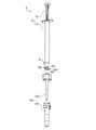
- FIG. 1Ais a perspective view of a medical liquid injector according to Embodiment 1 of the present invention.
- FIG. 1Bis a cross-sectional view of the medical fluid injector according to Embodiment 1 of the present invention.
- FIG. 2is an exploded perspective view of the medical liquid injector according to the first embodiment of the present invention.
- FIG. 3Ais a perspective view of a liquid collecting needle constituting the medical liquid injector according to Embodiment 1 of the present invention.
- FIG. 3Bis a cross-sectional view of the liquid collection needle.
- FIG. 4is an enlarged cross-sectional view showing a connection portion between a liquid collecting needle and a tube tip in the medical liquid injector according to the first embodiment of the present invention.
- FIG. 1Ais a perspective view of a medical liquid injector according to Embodiment 1 of the present invention.
- FIG. 1Bis a cross-sectional view of the medical fluid injector according to Embodiment 1 of the present invention.
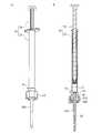
- FIG. 5Ais a perspective view of a medical fluid injector according to Embodiment 2 of the present invention.
- FIG. 5Bis a cross-sectional view of the medical fluid injector according to Embodiment 2 of the present invention.
- FIG. 6is an enlarged cross-sectional view showing a connection portion between a liquid collecting needle and a small diameter portion in a medical liquid injector according to Embodiment 2 of the present invention.
- FIG. 7Ais a perspective view of a medical liquid injector according to Embodiment 2 of the present invention, from which a liquid collection needle has been removed.
- FIG. 7Bis a cross-sectional view of the medical liquid injector according to Embodiment 2 of the present invention from which the liquid collection needle has been removed.
- FIG. 8Ais a perspective view of a medical liquid injector according to a third embodiment of the present invention.
- FIG. 8Bis a cross-sectional view of the medical fluid injector according to Embodiment 3 of the present invention.
- FIG. 9is an exploded perspective view of the medical liquid injector according to the third embodiment of the present invention.
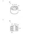
- FIG. 10Ais a perspective view seen from above of a liquid collecting needle constituting a medical liquid injector according to Embodiment 3 of the present invention.
- FIG. 10Bis a perspective view of the liquid collection needle viewed from below.
- FIG. 11is a cross-sectional perspective view of a liquid collecting needle according to Embodiment 3 of the present invention.
- FIG. 12is a plan view of a liquid collection needle according to Embodiment 3 of the present invention.
- FIG. 13Ais a perspective view seen from above the nozzle tip constituting the medical fluid injector according to Embodiment 3 of the present invention.
- FIG. 13Bis a perspective view of the nozzle chip as seen from below.
- FIG. 14is a cross-sectional perspective view of a nozzle chip according to the third embodiment of the present invention.
- FIG. 15Ais a perspective view of a liquid collection nozzle in which a nozzle tip is attached to a liquid collection needle in Embodiment 3 of the present invention.
- FIG. 15Bis a cross-sectional view of the liquid collection nozzle.
- FIG. 16Ais a perspective view showing a state in which a collecting needle is attached to an injector body in Embodiment 3 of the present invention.
- 16Bis a cross-sectional view of FIG. 16A.
- FIG. 17:is the perspective view which showed the state which stabbed the medical liquid injection device concerning Embodiment 3 of this invention at the opening of the container.
- FIG. 18is a cross-sectional view showing another liquid collection nozzle in Embodiment 3 of the present invention.
- FIG. 19Ais a perspective view of an injector of a conventional injector with a collection tip used in the simple suspension method.
- FIG. 19Bis a cross-sectional view of the injector with a collection tip.
- FIG. 19Ais a perspective view of an injector of a conventional injector with a collection tip used in the simple suspension method.
- FIG. 19Bis a cross-sectional view of the injector with a collection tip.
- FIG. 20is an enlarged cross-sectional view showing a cylindrical tip of an injector equipped with a conventional tip and the vicinity thereof.
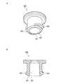
- FIG. 21Ais a perspective view of a male connector (patient-side connector) considered as ISO80369-3.
- FIG. 21Bis a cross-sectional view along a plane including the central axis of the male connector.
- FIG. 22Ais a perspective view of a female connector (container side connector) considered as ISO80369-3.
- FIG. 22Bis a cross-sectional view along a plane including the central axis of the female connector.
- the barrel and the liquid needlemay be separate parts.
- the liquid collection needleis detachably attached to the tube tip. According to such a preferable configuration, when the amount of the drug solution in the container is large, the drug solution can be administered to the patient using the same injector by repeatedly attaching and removing the sample collecting needle to and from the tube tip a plurality of times. .
- a fitting shape to be fitted to the inner peripheral surface of the tubular portionis formed on the liquid collecting needle. According to such a preferable configuration, the liquid collecting needle can be firmly held on the tube tip.
- the barrel and the liquid collecting needlemay constitute a single molded part.
- the liquid collection needle and the barrelcan be irreversibly separated at the boundary between the base end and the small diameter portion.
- the liquid collecting needlecan be removed from the barrel. Therefore, after that, the tube tip can be connected to the patient side connector. Since the syringe from which the collection needle has been removed cannot be reused, the likelihood of patient infection due to reuse of the syringe is reduced. Further, the number of members constituting the injector can be reduced, and the manufacture of the injector becomes easy.
- the medical liquid injector of the present inventionmay further include a nozzle tip that is detachably attached to the liquid collection needle so as to cover at least the tip of the liquid collection needle.
- the nozzle tipincludes an opening provided so as to communicate with the flow path of the liquid collection needle when the nozzle chip is attached to the liquid collection needle. According to such a preferable configuration, an injector that can be used in the simple suspension method can be used for collecting milk if a nozzle tip is attached to the liquid collecting needle.
- a lock mechanismmay be provided for maintaining a state where the nozzle tip is attached to the liquid collection needle. According to such a preferable configuration, it is possible to reduce the possibility that the nozzle tip is unintentionally dropped from the liquid collecting needle.
- a male taper surface whose outer diameter decreases as it approaches the tipmay be provided on the outer peripheral surface of the nozzle tip. According to such a preferable configuration, the syringe can be pierced into the container in a state where the male tapered surface is fitted to the edge of the opening of the container. This is advantageous for preventing contamination of the tip of the nozzle tip and preventing contamination and evaporation of the liquid in the container.
- the tubular portion, the screw-like protrusion, and the female taper surfaceconform to ISO 80369-3.
- the tube tip of the injectorcan be connected to a male connector (patient side connector) conforming to ISO 80369-3 with liquid tightness and connection strength conforming to ISO 80369-3.
- FIG. 1Ais a perspective view of a medical liquid injector (hereinafter simply referred to as “injector”) 1 according to Embodiment 1 of the present invention.
- FIG. 1Bis a cross-sectional view of the injector 1.
- FIG. 2is an exploded perspective view of the injector 1.
- the injector 1includes an injector body 10 having a barrel (outer cylinder) 12 and a plunger 18, and a liquid collection needle 20.
- the plunger 18 sideis referred to as the “upper” side of the injector 1
- the liquid collection needle 20 sideis referred to as the “lower” side of the injector 1.
- the direction connecting the plunger 18 and the collection needle 20is referred to as the “longitudinal direction” of the injector 1.
- the barrel 12has a hollow cylindrical shape, one end (upper end) is opened, and the other end (lower end) is provided with a tube tip (nozzle) 14.
- a plunger 18is inserted into the opening at the upper end of the barrel 12 so as to be insertable / removable.
- a gasket 19is attached to the tip of the plunger 18. The gasket 19 slides in the longitudinal direction on the inner peripheral surface of the barrel 12 while forming a liquid-tight seal with the inner peripheral surface of the barrel 12.
- a pair of finger hook flanges 17protrude outward from the upper end of the barrel 12.
- a scale (not shown) indicating the amount of liquid in the barrel 12is provided on the outer peripheral surface of the barrel 12.
- the barrel tip 14 of the barrel 12is the same as the female connector (container side connector) 920 shown in FIGS. 22A and 22B so that it can be connected to a male connector (patient side connector) 910 (see FIGS. 21A and 21B).
- a female connector conforming to ISO 80369-3is provided.
- 1A, 1B, and 2the same members as those shown in FIGS. 22A and 22B are denoted by the same reference numerals.
- a small-diameter portion 16having an inner diameter smaller than these is formed between the liquid storage portion 15 and the tubular portion 921.
- the liquid storage part 15is a part of the barrel 12 where the plunger 18 is inserted and removed, and is a part capable of storing the chemical liquid.
- the small diameter portion 16prevents the plunger 18 inserted into the liquid storage portion 15 from entering the tubular portion 921 of the tube tip 14.
- FIG. 3Ais a perspective view of the liquid collection needle 20, and FIG. 3B is a cross-sectional view of the liquid collection needle 20.
- the collection needle 20has an elongated bar shape as a whole.
- the flow path 28penetrates the liquid collection needle 20 in the longitudinal direction, and is opened at the proximal end (the end on the side inserted into the barrel tip 14 of the barrel 12) and the distal end of the liquid collection needle 20.
- a connecting tube 21is formed at the proximal end of the liquid collecting needle 20.
- the outer peripheral surface of the connecting cylinder 21is a cylindrical surface having a constant outer diameter in the longitudinal direction.
- a plurality (four in this example) of ribs 22project outward from the outer peripheral surface of the liquid collection needle 20 along the radial direction, adjacent to the connection tube 21.
- Each rib 22extends along the longitudinal direction of the liquid collection needle 20.
- the outer diameter of the liquid collection needle 20 at the rib 22decreases as the connection tube 21 is approached. More specifically, the top surface (surface facing outward in the radial direction of the rib 22) 22t of the rib 22 is on the outer peripheral surface 912 of the male member 911 of the male connector 910 described above (see FIGS. 21A and 21B).
- the top surface 22t of the rib 22is along a tapered surface (conical surface) having the same taper angle and diameter as the female tapered surface formed on the inner peripheral surface 922 of the tubular portion 921 of the tube tip 14.
- the connecting tube 21 of the liquid collection needle 20is inserted into the tube tip 14 of the barrel 12. As shown in FIG. 4, the connection tube 21 of the liquid collection needle 20 is fitted into the small diameter portion 16 of the barrel 12.
- the outer diameter of the connecting tube 21is substantially the same as the inner diameter of the small diameter portion 16. Therefore, a liquid-tight seal is formed between the outer peripheral surface of the connecting tube 21 and the inner peripheral end of the small diameter portion 16.
- the flow path 28 of the liquid collection needle 20communicates with the liquid storage unit 15.
- the top surface 22t of the rib 22 of the connection tube 21is in contact with the inner peripheral surface 922 of the tubular portion 921 of the barrel 12. As described above, the top surface 22t is along the same male tapered surface as the outer peripheral surface 912 of the male member 911 of the male connector 910 (see FIGS. 21A and 21B). Accordingly, the top surface 22t is in surface contact with the inner peripheral surface 922 of the tubular portion 921. For this reason, the rib 22 and the tubular portion 921 are fitted, and the liquid collection needle 20 is firmly connected to the tube tip 14. The tip of the liquid collection needle 20 protrudes greatly from the tube tip 14 (see FIG. 1A).
- the liquid collection needle 20is only fitted to the tube tip 14, the liquid collection needle 20 can be repeatedly attached to and detached from the tube tip 14.
- the material of the barrel 12, the plunger 18 (excluding the gasket 19), and the liquid collection needle 20is not limited, but is preferably a material having a shape retaining property, and further, a machine that is not substantially deformed by an external force. It is preferable that it is a hard material (hard material) which has specific strength (rigidity).
- resin materialssuch as polypropylene (PP), polycarbonate (PC), polyacetal (POM), polystyrene, polyamide, polyethylene, hard polyvinyl chloride, acrylonitrile-butadiene-styrene copolymer (ABS) can be used.
- PPPolypropylene
- PCpolycarbonate
- ABSacrylonitrile-butadiene-styrene copolymer
- the material of the gasket 19is not limited, but for example, butyl rubber, isoprene rubber, styrene thermoplastic elastomer, or the like can be used.
- the injector 1can be used when the simple suspension method described above is performed.
- the simple suspension method using the injector 1is performed as follows.
- an injector 1is prepared in which a collection needle 20 is attached to a tube tip 14 of an injector body 10.
- the tip of the liquid collection needle 20is immersed in the chemical solution in which the tablet is disintegrated, and the plunger 18 is operated to suck the chemical solution into the barrel 12.
- the suction amount of the chemical solutionis measured by using the position of the gasket 19 seen through the barrel 12 and a scale (not shown) attached to the barrel 12.
- the collecting needle 20is removed from the tube tip 14 (see FIG. 2).
- the tube tip 14is connected to the male connector 910 (see FIGS. 21A and 21B).
- the male connector 910is a patient-side connector provided at the upstream end of a catheter inserted into a patient's body or the upstream end of an extension tube connected to the catheter. Since the tube tip 14 is a female connector 920 compliant with ISO 80369-3, the tube tip 14 and the male connector 910 are connected with liquid tightness and connection strength according to ISO 80369-3. In this state, the plunger 18 is pushed into the barrel 12 until the gasket 19 hits the small-diameter portion 16 to administer the drug solution in the liquid storage portion 15 to the patient. Thereafter, the tube tip 14 is separated from the male connector 910.
- the work (suction work) of sucking the chemical solution in the container into the injector main body 10is performed by attaching the liquid collecting needle 20 to the tube tip 14, while the chemical solution in the injector main body 10 is used.
- the operation (administration operation)is performed by connecting the tube tip 14 to the male connector 910 without using the liquid collection needle 20.
- the tip of the liquid collection needle 20is immersed in the chemical solution.
- the connection tube 21 of the liquid collection needle 20is liquid-tightly connected to the small diameter portion 16 of the barrel 12. Therefore, the chemical solution does not adhere to the outer peripheral surface of the tubular portion 921 including the screw-shaped protrusion 925.
- the chemical solutiondoes not adhere to the inner peripheral surface (in particular, the female screw 915) of the outer tube 913 of the male connector 910. Therefore, even if the male connector 910 is left in the patient for a long period of time, the male connector 910 can be prevented from reaching an unsanitary state.
- the injector 1according to the first embodiment is advantageous in accurately managing the amount of the drug solution to be administered to the patient.
- the liquid collecting needle 20can be repeatedly attached to and detached from the tube tip 14. Therefore, when the amount of the drug solution to be administered to the patient is larger than the volume of the injector body 10, the same injector 1 is used by repeatedly attaching and removing the liquid collecting needle 20 to and from the tube tip 14.
- the medicinal solutioncan be administered to the patient.
- the number of ribs 22 formed in the vicinity of the connecting tube 21 of the liquid collection needle 20is arbitrary.
- An arbitrary fitting shape other than the rib 22 that fits on the inner peripheral surface (female taper surface) 922 of the tubular portion 921may be formed on the liquid collection needle 20.
- a male taper surface conforming to ISO 80369-3 formed on the outer peripheral surface 912 (see FIGS. 21A and 21B) of the male member 911 of the male connector 910may be formed on the liquid collection needle 20.
- an arbitrary protrusionfor example, an annular protrusion that is continuous in the circumferential direction
- contacts the inner peripheral surface 922 of the tubular portion 921may be formed on the liquid collection needle 20.
- the rib 22 that fits to the inner peripheral surface 922 of the tubular portion 921 or a fitting shape similar to thismay not be formed on the liquid collection needle 20.
- the liquid collection needle 20is held by the barrel 12 in the connection tube 21.
- the outer cylinder and the female screw compliant with ISO80369-3may be provided in the liquid collecting needle 20.
- the female screwcan be screwed into the screwing protrusion 925 of the tubular portion 921 in the same manner as the liquid collection needle 320 of the third embodiment described later.
- FIG. 5Ais a perspective view of an injector 2 according to Embodiment 2 of the present invention.
- FIG. 5Bis a cross-sectional view of the injector 2.
- the injector 2 according to the second embodimentis an injection according to the first embodiment, in which the liquid collecting needle 20 is a separate part from the barrel 12 in that the liquid collecting needle 220 forms one part integrally formed with the barrel 212. Different from vessel 1.
- the same members as those constituting the injector 1 of the first embodimentare denoted by the same reference numerals as those of the first embodiment, and detailed description thereof is omitted. .
- the liquid collection needle 220 of the second embodimenthas an elongated bar shape as a whole, like the liquid collection needle 20 of the first embodiment. As shown in FIG. 5B, the flow path 28 penetrates the liquid collection needle 220 in its longitudinal direction and opens at the tip of the liquid collection needle 220. As shown in FIG. 6, the proximal end 221 of the liquid collection needle 220 is connected to the small diameter portion 216 of the barrel 212. The flow path 28 of the liquid collection needle 220 communicates with the liquid storage unit 15.
- the barrel 212 and the collecting needle 220can be irreversibly broken and separated at the boundary between the base end 221 and the small diameter portion 216. That is, in FIG. 5A and FIG. 5B, when the barrel 212 and the collection needle 220 are gripped by separate hands and a bending force or a pulling force is applied to them, the boundary portion between the base end 221 and the small diameter portion 216 Breaks.
- the rib 22 formed in the liquid collection needle 20 of the first embodimentis not formed in the second embodiment. For this reason, when a bending force is applied, stress concentrates on the boundary portion between the base end 221 and the small diameter portion 216, and can be easily broken at the boundary portion.
- FIG. 5A and FIG. 5Bwhen the barrel 212 and the collection needle 220 are gripped by separate hands and a bending force or a pulling force is applied to them, the boundary portion between the base end 221 and the small diameter portion 216 Breaks.
- the rib 22 formed in the liquid collection needle 20 of the first embodimentis not formed in
- FIG. 7Ais a perspective view of the injector 2 (injector body 210) from which the collection needle 220 has been separated and removed in this manner
- FIG. 7Bis a cross-sectional view thereof.
- a fracture mark 216a formed by removing the liquid collection needle 220is formed at the inner peripheral end of the small diameter portion 216.
- the injector main body 210 from which the liquid collection needle 220 has been removedis substantially the same as the injector main body 10 of Embodiment 1 (see FIGS. 1A and 1B) except that it has a fracture mark 216a.
- each part constituting the injector 2can be the same as that of the injector 1 of the first embodiment.
- the barrel 212 and the liquid collection needle 220are integrally manufactured as a whole by an injection molding method or the like.
- the injector 2can be used when the simple suspension method described above is performed.
- the simple suspension method using the injector 2is performed as follows.
- an injector 2 in which a liquid collection needle 220 is integrated with a barrel 212is prepared.
- the tip of the liquid collection needle 220is immersed in the chemical solution in which the tablet is disintegrated, and the plunger 218 is operated to suck the chemical solution into the barrel 212.
- the amount of the chemical liquid suckedis measured using the position of the gasket 19 seen through the barrel 212 and a scale (not shown) attached to the barrel 212.
- liquid collection needle 220is separated from the barrel 212 and removed (see FIGS. 7A and 7B).
- the tube tip 14is connected to the male connector 910 (patient side connector, see FIGS. 21A and 21B), and the drug solution in the liquid storage unit 15 is administered to the patient.
- the operation of sucking the chemical solution in the container into the injector main body 210is performed in a state where the liquid collecting needle 220 is connected to the barrel 212, and the injector main body 210 thereafter.
- the operation (administration operation) of administering the drug solution to the patientis performed by separating and removing the liquid collection needle 220 and connecting the tube tip 14 to the male connector 910. Therefore, as in the first embodiment, in the suction operation, the chemical solution does not adhere to the outer peripheral surface of the tubular portion 921 including the screw-shaped protrusion 925.
- the chemical solutiondoes not adhere to the inner peripheral surface (in particular, the female screw 915) of the outer tube 913 of the male connector 910. Therefore, even if the male connector 910 is left in the patient for a long period of time, the male connector 910 can be prevented from reaching an unsanitary state.
- the base end 221 of the liquid collection needle 220 and the small diameter portion 216 of the barrel 212are connected in a liquid-tight manner (see FIG. 6).
- medical solution in the liquid storage part 15does not leak to the cylinder tip 14 side through between the base end 221 and the small diameter part 216.
- FIG.Therefore, when the simple suspension method is performed using the injector 2, no chemical solution remains in the tube tip 14. For this reason, in this Embodiment 2, possibility that a patient will administer the chemical
- the injector 2 of the second embodimentsince the barrel 212 and the liquid collection needle 220 are one part, the number of members constituting the injector 2 can be reduced, and the manufacture of the injector 2 is easy. .
- the injector 2 of the second embodimentis a so-called disposable type that cannot be reused. Since the simple suspension method will always be carried out using a new and clean injector 2, the possibility of patient infection is further reduced.
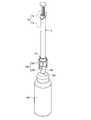
- FIG. 8Ais a perspective view of an injector 3 according to Embodiment 3 of the present invention.
- FIG. 8Bis a cross-sectional view of the injector 3.
- FIG. 9is an exploded perspective view of the injector 3.
- the injector 3includes an injector body 10 having a barrel (outer cylinder) 12 and a plunger 18, a liquid collection needle 320, and a nozzle tip 350.
- the liquid collection needle 320 and the nozzle tip 350constitute a liquid collection nozzle 360.
- the injector body 10 of the third embodimentis the same as the injector body 10 of the first embodiment.
- the same members as those constituting the injector 1 of the first embodimentare denoted by the same reference numerals as those of the first embodiment, and detailed description thereof is omitted. .
- FIG. 10Ais a perspective view of the liquid collection needle 320 as viewed from above
- FIG. 10Bis a perspective view of the liquid collection needle 320 as viewed from below
- FIG. 11is a cross-sectional perspective view of the liquid collection needle 320
- FIG. 12is a plan view of the liquid collection needle 320.
- an outer cylinder 313 surrounding the liquid collection needle 320is provided in the vicinity of the connection cylinder 21.
- the liquid collection needle 320 and the outer cylinder 313are connected via a bottom plate 314 that protrudes from the liquid collection needle 320 in a flange shape along the radial direction.
- a female screw 315is provided on the inner peripheral surface of the outer cylinder 313 facing the liquid collection needle 320.
- the female screw 315is compatible with the female screw 915 (see FIGS. 21A and 21B) provided in the male connector 910 described above, and conforms to ISO80369-3. Therefore, the female screw 315 can be screwed with a screw-like projection (male screw) 925 provided on the tube tip 14 of the barrel 12 in accordance with ISO80369-3.
- a substantially octagonal prism surfaceis provided on the outer peripheral surface of the outer cylinder 313 so that the outer cylinder 313 can be gripped and a rotational force can be easily applied to the liquid collection needle 320.
- the shape of the outer peripheral surface of the outer cylinder 313is not limited to this, It can change suitably.
- the bottom plate 314is provided with two through holes 322 having a substantially “L” shape in plan view.
- the two through holes 322are 180 degrees rotationally symmetric with respect to the central axis of the liquid collection needle 320.
- An inclined surface 324is provided in the vicinity of the edge of the through hole 322 on the upper surface of the bottom plate 314. The inclined surface 324 is inclined to rise as it rotates clockwise with respect to the liquid collection needle 320.
- a tapered surface (male tapered surface) 328whose outer diameter decreases as it approaches the distal end is provided on the outer peripheral surface near the distal end of the liquid collection needle 320.
- FIG. 13Ais a perspective view seen from above the nozzle tip 350
- FIG. 13Bis a perspective view seen from below the nozzle tip 350
- FIG. 14is a sectional perspective view of the nozzle tip 350.
- the nozzle tip 350has a hollow, substantially cylindrical shape.
- the inner diameter of the inner peripheral surface that defines the inner cavity 351 of the nozzle tip 350is such that the portion of the liquid collection needle 320 (see FIGS. 8A and 8B) below the bottom plate 314 can be inserted. It is set to be equal to or larger than the outer diameter of the part.
- the inner diameter of the nozzle tip 350is minimum at the opening 352 provided at the tip (lower end) thereof.
- the inner diameter of the opening 352is preferably set to be approximately the same as the inner diameter of the opening (see FIG. 10B) at the tip of the flow path 28 of the liquid collection needle 320.
- a taper surface (female taper surface) 358 having an inner diameter that decreases as it approaches the opening 352is provided adjacent to and above the opening 352.
- the female taper surface 358has the same taper angle and diameter as the male taper surface 328 (see FIG. 10A) provided near the tip of the liquid collection needle 320.
- the protrusion 354includes a vertical portion 354a extending upward from the upper end of the nozzle tip 350, and an engagement portion 354b protruding outward from the upper end of the vertical portion 354a along the radial direction.
- the two protrusions 354are 180 degrees rotationally symmetric with respect to the central axis of the nozzle tip 350.
- the nozzle chip 350is provided with two gripping portions 356.
- the gripping portion 356protrudes outward along the radial direction from the upper end of the nozzle tip 350 and then extends downward.
- the grip portion 356is provided to make it easy to apply a rotational force to the nozzle tip 350.
- the shape of the holding part 356is not limited to this embodiment.
- a regular polygonal column surface(regular hexagonal column surface, regular octagonal column surface, etc.) may be provided on the outer peripheral surface of the nozzle chip 350, and this may be used as a gripping portion.
- the grip portionmay be omitted.
- the outer peripheral surface of the nozzle tip 350is provided with a tapered surface (male tapered surface) 355 whose outer diameter decreases as it approaches the tip.
- a circular flat surface 353 perpendicular to the longitudinal direction of the nozzle chip 350is provided at the tip of the nozzle chip 350.
- the outer diameter of the distal end surface 353is larger than the outer diameter of the distal end of the liquid collection needle 320 (see FIG. 10B).
- An opening 352is provided in the center of the distal end surface 353.
- the outer peripheral edge of the front end surface 353is smoothly chamfered.
- FIG. 15Ais a perspective view of the liquid collection nozzle 360 in which the nozzle tip 350 is attached to the liquid collection needle 320.
- FIG. 15Bis a cross-sectional view of the liquid collection nozzle 360.
- the mounting of the nozzle tip 350 to the liquid collection needle 320is performed as follows.
- the liquid collection needle 320is inserted into the lumen 351 of the nozzle tip 350, and the protrusion 354 of the nozzle tip 350 is inserted into the through hole 322 provided in the bottom plate 314 of the liquid collection needle 320.
- the liquid collection needle 320 and the nozzle tip 350are rotated in opposite directions (that is, when viewed from above, the liquid collection needle 320 is rotated counterclockwise with respect to the nozzle tip 350).
- the engaging portion 354b (see FIGS. 13A and 13B) of the nozzle tip 350slides on the inclined surface 324 (see FIG. 12) of the liquid collection needle 320.
- the blood collection needle 320is inserted deeper into the lumen 351 of the nozzle tip 350 as the nozzle tip 350 rotates relative to the liquid collection needle 320.
- the liquid collection needle 320moves relative to the nozzle tip 350 along its longitudinal direction.
- the nozzle tip 350is rotated with respect to the liquid collection needle 320 until the vertical portion 354a of the protrusion 354 of the nozzle chip 350 comes into contact with the end of the edge defining the through hole 322 of the liquid collection needle 320 in the rotation direction.
- 15A and 15Bshow this state.
- the male tapered surface 328 of the liquid collection needle 320 and the female tapered surface 358 of the nozzle tip 350are fitted in a liquid-tight and air-tight manner.
- the tip of the liquid collection needle 320is accommodated in the nozzle tip 350 and covered with the nozzle tip 350.
- the opening 352 at the tip of the nozzle tip 350 and the flow path 28 of the liquid collection needle 320communicate with each other.
- the relative rotation of the nozzle tip 350 with respect to the liquid collection needle 320applies a rotational force by holding the outer peripheral surface of the outer cylinder 313 of the liquid collection needle 320 and the grip portion 356 of the nozzle tip 350 with different hands. This can be easily performed.
- the material of the liquid collection needle 320is not limited, but the same material as that of the liquid collection needle 20 described in the first embodiment can be used.
- the nozzle chip 350is preferably made of a material having a relatively low hardness because it directly touches human skin. Specifically, a resin material such as polypropylene (PP) or polyethylene (PE) can be used.
- PPpolypropylene
- PEpolyethylene
- the liquid collection needle 320 and the nozzle tip 350can be integrally manufactured as a whole by an injection molding method or the like using the above resin material.
- the injector 3 of the present embodimentcan be used for collecting milk as well as the injectors 1 and 2 of the first and second embodiments.
- the simple suspension method using the injector 3will be described.
- the nozzle tip 350is removed from the injector 3 shown in FIGS. 8A and 8B. That is, as shown in FIGS. 16A and 16B, only the liquid collection needle 320 is attached to the injector body 10.
- the connection tube 21 of the liquid collection needle 320is fitted into the small-diameter portion 16 of the barrel 12, and the connection tube 21 and the small-diameter portion 16 are liquid-tight.
- the flow path 28 of the liquid collection needle 320communicates with the liquid storage part 15 of the barrel 12.
- the female screw 315 of the liquid collection needle 320is screwed with the screw-shaped protrusion 925 of the barrel 12.
- the tip of the liquid collection needle 320is immersed in a chemical solution that has collapsed the tablet, and the plunger 18 is operated to suck the chemical solution into the barrel 12.
- the liquid collection needle 320is removed from the tube tip 14 (see FIG. 9).
- the tube tip 14is connected to the male connector 910 (see FIGS. 21A and 21B), and the drug solution in the liquid storage unit 15 is administered to the patient. Thereafter, the tube tip 14 is separated from the male connector 910.
- breast milk collection using the injector 3will be described.
- FIG. 8A and FIG. 8Bbreast milk collection is performed in a state where the collection needle 320 and the nozzle tip 350 are attached to the injector body 10.
- the tip surface 353 of the nozzle tip 350is applied to the nipple, and the plunger 18 is operated to suck the breast milk adhering to the nipple into the barrel 12 through the opening 352.
- the work (suction work) of sucking the chemical solution in the container into the injector body 10is performed by attaching the liquid collecting needle 320 to the tube tip 14.
- the operation (administration operation) of administering the drug solution in the injector body 10 to the patientis performed by connecting the tube tip 14 to the male connector 910 without using the liquid collection needle 320. Therefore, as in the first embodiment, in the suction operation, the chemical solution does not adhere to the outer peripheral surface of the tubular portion 921 including the screw-shaped protrusion 925.
- the chemical solutiondoes not adhere to the inner peripheral surface (in particular, the female screw 915) of the outer tube 913 of the male connector 910. Therefore, even if the male connector 910 is left in the patient for a long period of time, the male connector 910 can be prevented from reaching an unsanitary state.
- the injector 3 according to the third embodimentis advantageous for accurately managing the amount of the drug solution to be administered to the patient.
- the injector 3 of the third embodiment equipped with the nozzle tip 350can be preferably used for collecting milk.
- breast milkis sucked into a barrel in a state in which a tube tip of an injector (syringe) is directly applied to a teat.
- breast milkcan be collected using a conventional injector 950 (see FIGS. 19A and 19B) that is not equipped with the liquid collection chip 940.
- a circular plane having a relatively large areais provided at the tip of the tube tip 954, and a flow path is opened at the center thereof. This circular plane is applied to the nipple to suck the breast milk.
- the nozzle tip 350 of the third embodimentincludes a tip surface 353 that is equal to or larger than the tip surface of the tube tip 954, breast milk can be collected by applying the tip surface 353 to the nipple.
- the tips of the liquid collection needles 20, 220, and 320 of Embodiments 1 to 3have a relatively small diameter so that a trace amount of liquid in the container can be collected without remaining.
- the tips of the collection needles 20, 220, and 320are directly applied to the nipple, the mother may feel pain.
- the injector body 10, 210(see FIGS. 2 and 7A) from which the collection needles 20, 220, 320 are removed has a large inner diameter cavity in the tubular portion 921 of the tube tip 14, so It is difficult to suck.
- the nozzle tip 350 of the injector 3 of Embodiment 3has a tip surface 353 having a relatively large diameter and a large area, no pain is felt even if the tip of the nozzle tip 350 directly touches the skin.
- the tip surface 353 of the nozzle tip 350By attaching the tip surface 353 of the nozzle tip 350 to the nipple, a small amount of milk can be sucked with little residual liquid.
- both the simple suspension method and the collection of breast milkcan be performed using the common injector body 10.
- the nozzle tip 350is used by being attached to the liquid collection needle 320.
- a breast milk collection nozzle having an outer shape equivalent to that of the nozzle tip 350is created, and when breast milk is collected, the breast milk collection nozzle is attached to the tube tip 14 instead of the liquid collection needle 320.
- Such thick milk collection nozzlesgenerally have poor resin moldability.
- the nozzle chip 350 of this embodimentcan be thinned, it is excellent in resin moldability.
- breast milkcan be sucked into the barrel 12 from the opening 352 of the nozzle tip 350 through the flow path 28 of the liquid collection needle 320.
- the amount of breast milk that flows into the gap between the nozzle tip 350 and the collection needle 320 and does not flow into the flow path 28can be reduced. Therefore, the seal between the liquid collection needle 320 and the nozzle tip 350 is advantageous for efficiently collecting breast milk.
- the inclined surface 324 (see FIG. 12) of the liquid collection needle 320is advantageous in improving the sealing performance between the liquid collection needle 320 and the nozzle tip 350.
- a male taper surface 355is provided on the outer peripheral surface of the nozzle tip 350 (see FIG. 13A). For this reason, for example, as shown in FIG. 17, the injector 3 can be pierced into the opened opening 391 of a container (for example, a container for distilled water) 390.
- the male tapered surface 355 of the nozzle tip 350is fitted to the edge of the opening 391 of the container 390, and the opening 391 is closed with the nozzle tip 350. It is advantageous to temporarily leave the injector 3 and the container 390 in this state in order to prevent contamination of the tip of the nozzle tip 350 and to prevent contamination and evaporation of the liquid (for example, distilled water) in the container 390.
- the male taper surface 355is not essential in the present invention.
- the liquid collection needle 320includes an outer cylinder 313 (see FIG. 10A).
- the outer cylinder 313covers the barrel tip 14 of the barrel 12 (particularly, the screw-shaped protrusion 925 and the vicinity thereof).
- the outer cylinder 313prevents the cylinder tip 14 from being contaminated by touching the operator's finger or the like. Therefore, the outer cylinder 313 is advantageous for ensuring the sanitary condition of the cylinder tip 14. Thereby, the sanitary state of the male connector 910 to which the tube tip 14 is connected can be kept good, and infection of the patient can also be prevented.
- the operatorcan attach and detach the liquid collection needle 320 to the tube tip 14 of the barrel 12 without touching the tip of the liquid collection needle 320 by holding the outer peripheral surface of the outer cylinder 313.
- the operation of mounting the liquid collection nozzle 360 (see FIG. 15A) having the nozzle tip 350 attached to the liquid collection needle 320 to the tube tip 14 of the barrel 12can be similarly performed by holding the outer peripheral surface of the outer tube 313. .
- the outer cylinder 313is provided with a female screw 315 that can be screwed into the screw-shaped protrusion 925 of the barrel 12.
- the liquid collection needle 320does not include the fitting shape 22 (see FIG. 3A) fitted to the inner peripheral surface 922 of the tubular portion 921 of the barrel 12 provided in the liquid collection needle 20 of the first embodiment. However, it can be securely attached to the barrel 12.
- the female screw 315 provided on the liquid collection needle 320 and the screw-like protrusion 925 provided on the barrel 12are so-called right-hand screws.
- the engagement structure between the protrusion 354 of the nozzle tip 350 and the bottom plate 314 of the liquid collection needle 320rotates the liquid collection needle 320 counterclockwise with respect to the nozzle tip 350 when viewed from above. And the engagement is released when the collection needle 320 is rotated in the clockwise direction with respect to the nozzle tip 350. Is the same as the so-called left-hand thread.
- the barrel 12 and the nozzle tip 350are gripped by different hands with the liquid collection needle 320 and the nozzle tip 350 attached to the barrel 12, and viewed from the barrel 12 side.
- the screw tip 925 of the barrel 12 and the female screw 315 of the liquid collection needle 320are not loosened, and the nozzle tip 350 is moved. It can be separated from the collection needle 320.
- the barrel 12 and the liquid collection needle 320can be removed with one hand in the state of FIGS. 8A and 8B. Regardless of which of the tubes 313 is held, the nozzle tip 350 can be reliably removed from the liquid collection needle 320 if the nozzle tip 350 is held with the other hand and rotated as described above.
- the engaging portion 354b of the nozzle tip 350has the bottom plate 314 of the liquid collection needle 320 as a lock mechanism for stably maintaining the state where the nozzle tip 350 is attached to the liquid collection needle 320.
- An engagement structure that engages withis provided.
- the lock mechanismis not limited to such an engagement structure, and any configuration can be adopted.
- the lock mechanismmay be a screwed structure.
- a screw-like protrusionfor example, a male screw
- a female screw that engages with the screw-like protrusionmay be provided on the inner peripheral surface near the upper end of the nozzle chip 350.
- the outer cylinder 313 of the liquid collection needle 320is extended below the bottom plate 314, a female screw is provided on the inner peripheral surface of the extended outer cylinder 313, and the outer peripheral surface near the upper end of the nozzle tip 350 is You may provide the screwing permite
- protrusionfor example, male screw
- the threaded structurecan be advantageous in improving the sealing performance between the liquid collection needle 320 and the nozzle tip 350.
- the screwing structure constituting the locking mechanismis configured in conformity with the left-hand thread, as shown in FIGS. 8A and 8B. In a state where 320 and the nozzle tip 350 are mounted, it is advantageous to reliably remove the nozzle tip 350 from the liquid collection needle 320 without loosening of the screw projection 925 and the female screw 315.
- a tapered surface (male tapered surface) 329whose outer diameter decreases as it approaches the tip is provided on the outer circumferential surface of the liquid collection needle 320, and the male tapered surface 329 is disposed on the inner circumferential surface of the nozzle tip 350.
- a female taper surface 359having the same diameter and taper angle is provided.
- the nozzle tip 350can be stably held by the liquid collection needle 320 by the frictional force between the male tapered surface 329 and the female tapered surface 359 when they are fitted.
- An airtight and liquid tight sealis formed between the male taper surface 329 and the female taper surface 359.
- the nozzle tip 350is made of a flexible material that is relatively easy to deform, such as rubber such as natural rubber, isoprene rubber, and silicone rubber, and thermoplastic elastomer such as styrene elastomer, olefin elastomer, and polyurethane elastomer. You may comprise the material (it is also called an elastomer) which has rubber elasticity.
- an airtight and liquid-tight sealis formed between the male tapered surfaces 328 and 329 of the liquid collecting needle 320 and the female tapered surfaces 358 and 359 of the nozzle tip 350.
- the seal between 350may be formed by other than the two tapered surfaces to be fitted.
- the front end surface of the liquid collection needle 320surface surrounding the opening on the front end side of the flow path 28
- the inner surface of the front end of the nozzle chip 350surface opposite to the flat surface 353 are arranged in the longitudinal direction of the liquid collection needle 320. By abutting, an airtight and liquid tight seal may be formed between both surfaces.
- the liquid collection needle 320includes the female screw 315 that can be screwed with the screw-shaped protrusion 925 of the barrel 12 on the inner peripheral surface of the outer cylinder 313.
- the female screw 315can be omitted.
- the female screw 315 and the outer cylinder 313can be omitted.
- the liquid collection needle 320may have a fitting shape that fits on the inner peripheral surface of the tubular portion 921 of the barrel 12 described in the first embodiment.
- the tip surface 353 of the nozzle tip 350does not need to be an accurate plane. For example, it may be projected or recessed in a dome shape. However, the corners are preferably rounded and chamfered so as not to have sharp edges.
- the nozzle tip that covers the tip of the collecting needle described in the third embodimentmay be applied to the collecting needles 20 and 220 of the first and second embodiments.
- the shape of the outer peripheral surface of the connecting cylinder 21is not limited to a cylindrical surface. As long as the small diameter portion 16 can be connected in a liquid-tight manner, the shape of the connecting cylinder 21 is arbitrary.
- the outer peripheral surface of the connecting tube 21may be a male tapered surface (conical surface) whose outer diameter decreases as it approaches the tip.
- the connecting cylinder 21may be liquid-tightly connected to the small diameter portion 16 by contacting the small diameter portion 16 instead of fitting the connecting cylinder 21 into the small diameter portion 16.
- a cylindrical protrusion protruding toward the lower sideis formed in the small-diameter portion 16, and the cylindrical protrusion is fitted into the connecting cylinder 21, so that the connecting cylinder 21 has a diameter. It may be liquid-tightly connected to the small portion 16.
- the collection needle of the present inventionis not limited to the simple suspension method. It can also be used to suck (water, chemicals, blood, etc.) into the syringe body.
- the present inventionis not limited, but can be widely used as an injector used for collecting an arbitrary liquid (water, medicinal solution, breast milk, blood, etc.) in the medical field.
- itcan be preferably used as an injector for use in the simple suspension method.
Landscapes
- Health & Medical Sciences (AREA)
- Life Sciences & Earth Sciences (AREA)
- Animal Behavior & Ethology (AREA)
- Veterinary Medicine (AREA)
- Public Health (AREA)
- General Health & Medical Sciences (AREA)
- Heart & Thoracic Surgery (AREA)
- Hematology (AREA)
- Engineering & Computer Science (AREA)
- Biomedical Technology (AREA)
- Anesthesiology (AREA)
- Vascular Medicine (AREA)
- Pharmacology & Pharmacy (AREA)
- Pulmonology (AREA)
- Fluid Mechanics (AREA)
- Physics & Mathematics (AREA)
- Pediatric Medicine (AREA)
- Pathology (AREA)
- Medical Informatics (AREA)
- Molecular Biology (AREA)
- Surgery (AREA)
- Infusion, Injection, And Reservoir Apparatuses (AREA)
- Medical Preparation Storing Or Oral Administration Devices (AREA)
Abstract
Description
Translated fromJapanese本発明は、簡易懸濁法を行う際に好ましく使用することができる医療用採液注入器に関する。The present invention relates to a medical liquid injector that can be preferably used when performing a simple suspension method.
経口によらずに患者に栄養や薬剤を投与する方法として経腸栄養療法が知られている。経腸栄養療法では、患者の鼻腔から胃又は十二指腸にまで挿入された経鼻カテーテル又は患者の腹に形成された胃ろうに挿入されたPEG(Percutaneous Endoscopic Gastrostomy)カテーテルが用いられる。経鼻カテーテル又はPEGカテーテル(以下、これらを総称して「カテーテル」という)を介して栄養剤、流動食(一般に「経腸栄養剤」と呼ばれる)、又は薬剤などの液状物が患者に投与される。患者に液状物を投与する際には、患者に挿入されたカテーテルの上流端又は当該カテーテルに接続された柔軟性を有するチューブ(一般に「延長チューブ」と呼ばれる)の上流端に設けられたコネクタ(以下「患者側コネクタ」という)と、液状物を貯留した容器又は当該容器に接続されたチューブに設けられたコネクタ(以下「容器側コネクタ」という)とを接続する。従来、患者側コネクタとしてメスコネクタが、また、容器側コネクタとしてオスコネクタが、それぞれ用いられていた(例えば特許文献1参照)。Enteral nutrition therapy is known as a method of administering nutrition and drugs to patients without oral administration. In enteral nutrition therapy, a nasal catheter inserted from the patient's nasal cavity into the stomach or duodenum or a PEG (Percutaneous Endoscopic Gastrostomy) catheter inserted into a gastric fistula formed in the patient's abdomen is used. A liquid such as a nutrient, liquid food (generally referred to as “enteral nutrient”), or a drug is administered to a patient via a nasal catheter or a PEG catheter (hereinafter collectively referred to as “catheter”). The When a liquid substance is administered to a patient, a connector provided at the upstream end of a catheter inserted into the patient or a flexible tube connected to the catheter (generally referred to as “extension tube”) ( (Hereinafter referred to as “patient-side connector”) and a connector (hereinafter referred to as “container-side connector”) provided in a container storing the liquid substance or a tube connected to the container. Conventionally, a female connector has been used as a patient-side connector, and a male connector has been used as a container-side connector (see, for example, Patent Document 1).
カテーテルが挿入された患者は、多くの場合、錠剤などの医薬品を口から直接飲み込むことができない。このような場合に医薬品を患者に投与する方法として「簡易懸濁法」が知られている。簡易懸濁法は以下の手順で行われる。最初に、容器内に錠剤を微温湯などで崩壊させた薬液を作成する。次いで、この薬液を注入器(シリンジ)内に吸引する。次いで、注入器の筒先を患者側コネクタに接続して、カテーテルを介して薬液を患者に投与する。・ In many cases, a patient with a catheter inserted cannot swallow a medicine such as a tablet directly from the mouth. In such a case, a “simple suspension method” is known as a method for administering a pharmaceutical product to a patient. The simple suspension method is performed according to the following procedure. First, a chemical solution in which a tablet is disintegrated with slightly warm water in a container is prepared. Next, this chemical solution is sucked into an injector (syringe). Next, the syringe tip is connected to the patient connector, and the drug solution is administered to the patient via the catheter.
簡易懸濁法では、注入器の筒先を患者側コネクタに接続する必要がある。図19Aは簡易懸濁法で使用される従来の採液チップ940付き注入器950の斜視図、図19Bは採液チップ940付き注入器950の断面図である。注入器950は、汎用されているシリンジと同様に、バレル(外筒)952と、バレル952に挿抜されるプランジャ958とを備える。バレル952の筒先(ノズル)954の外周面は、先端に近づくにしたがって外径が小さくなるテーパ面(オステーパ面)である。この筒先954に、採液チップ(以下、単に「チップ」という)940が着脱可能に装着されている。チップ940は、一端に、筒先954と液密に接続される基端部941を備え、他端に、採液針946を備える。チップ940を貫通する流路948が、基端部941と採液針946とを連通させている。簡易懸濁法では、図19A及び図19Bのようにチップ940を注入器950に装着した状態で、採液針946の先端を薬液に浸漬しながら、バレル952内に薬液を吸引する。その後、チップ940を注入器950から取り外し、筒先954を患者側コネクタ(メスコネクタ)に挿入して、バレル952内の薬液を患者に投与する。In the simple suspension method, it is necessary to connect the tip of the syringe to the connector on the patient side. FIG. 19A is a perspective view of a
ところで、近年、経腸栄養以外の分野で使用されるコネクタとの誤接続を防止するために、患者側コネクタとして図21A及び図21Bに示すオスコネクタ910が、また、容器側コネクタとして図22A及び図22Bに示すメスコネクタ920が、栄養系の医療機器に関する国際規格ISO80369-3として国際標準化することが検討されている。By the way, in recent years, in order to prevent erroneous connection with a connector used in fields other than enteral nutrition, the
図21A及び図21Bに示すオスコネクタ(患者側コネクタ)910は、筒形状のオス部材911と、オス部材911を取り囲む外筒913とを有する。オス部材911と外筒913とは、オス部材911の基端部から半径方向に沿ってフランジ状に突出した底板914を介して連結されている。オス部材911の外周面912は、先端に近づくにしたがって外径が小さくなるテーパ面(いわゆるオステーパ面)である。オス部材911には、その長手方向に沿ってオス部材911を貫通する流路917が形成されている。外筒913のオス部材911に対向する内周面には雌ネジ915が形成されている。A male connector (patient side connector) 910 shown in FIG. 21A and FIG. 21B has a
一方、図22A及び図22Bに示すメスコネクタ(容器側コネクタ)920は、オス部材911が挿入される円筒形状の管状部(メスルアー)921を有する。管状部921の内周面922は、先端に近づくにしたがって内径が大きくなるテーパ面(いわゆるメステーパ面)である。管状部921の外周面には螺状突起(雄ネジ)925が形成されている。On the other hand, the female connector (container-side connector) 920 shown in FIGS. 22A and 22B has a cylindrical tubular portion (male luer) 921 into which the
オスコネクタ910とメスコネクタ920とは、オス部材911を管状部921に挿入し、且つ、雌ネジ915と螺状突起925とを螺合させることにより接続される。オス部材911の外周面912と、管状部921の内周面922とは、径及びテーパ角度が同じテーパ面であるから、両者は液密な面接触をする。互いに螺合する雌ネジ915及び螺状突起925は、オスコネクタ910とメスコネクタ920との接続状態をロックするためのロック機構を構成する。オスコネクタ910とメスコネクタ920とは、液密性(液状物に圧力を加えてもオスコネクタとメスコネクタとの接続部分から液状物が漏れ出さない性質)と接続強度(接続されたオスコネクタとメスコネクタとが引張り力を加えても分離しない性質)に優れた接続を提供する。The
患者側コネクタが図21A及び図21Bに示すオスコネクタ910である場合、このオスコネクタ910に図19A及び図19Bに示した注入器950の筒先954を接続することはできない。簡易懸濁法で用いる注入器の筒先は、オスコネクタ910に接続することができるように、図22A及び図22Bに示すメスコネクタ920を有している必要がある。When the patient-side connector is the
筒先がメスコネクタ920を有する注入器を検討するに際して、以下の2点を考慮することが望まれる。When considering an injector having a
第1に、注入器を介して、オスコネクタ(患者側コネクタ)910の外筒913の内周面(特に雌ネジ915)に薬液が付着しないことが望まれる。First, it is desirable that the drug solution does not adhere to the inner peripheral surface (especially the female screw 915) of the
図21A及び図21Bに示したように、オスコネクタ910の外筒913の内周面には雌ネジ915が形成されている。雌ネジ915の谷内に薬液が付着すると、当該薬液を拭き取り除去することは困難である。オスコネクタ910が患者に挿入されたカテーテルの上流側端に設けられている場合には、オスコネクタ910はカテーテルとともに長期間にわたって患者に留置され続けることがある。例えばPEGカテーテルの交換は、一般に1~3ヶ月ごとに行われる。オスコネクタ910に薬液がこのように長期にわたって付着し続けると、オスコネクタ910は不衛生状態に至りうる。そして、遂には、オスコネクタ910内で菌が繁殖し、当該菌が患者の体内に侵入し、重症な合併症を引き起こす可能性がある。As shown in FIGS. 21A and 21B, a
注入器の筒先がメスコネクタ920を有する場合、管状部921の外周面(特に螺状突起925)に薬液が付着した状態でメスコネクタ920をオスコネクタ910に接続すると、薬液がオスコネクタ910の外筒913の内周面に付着してしまう。オスコネクタ910が上記のような不衛生状態に至るのを防止するためには、オスコネクタ910の外筒913の内周面(特に雌ネジ915)に注入器を介して薬液が付着しないようにする必要がある。When the syringe tip has a
第2に、患者に投与される薬液量が正確に管理されることが望まれる。図19A及び図19Bに示した従来のチップ940付き注入器950は、作業者の操作方法によっては薬液量を正確に管理することができない場合があるという課題を有している。Second, it is desirable to accurately manage the amount of drug solution administered to the patient. The
即ち、従来のチップ940付き注入器950を用いて簡易懸濁法を行う場合、図19A及び図19Bで説明したように、注入器950にチップ940を装着した状態で、薬液をバレル952内に吸引する。薬液の吸引量は、バレル952の外周面に付された目盛り(図示せず)を用いて計量される。図20は、チップ940が装着された注入器950の筒先954及びその近傍を示した拡大断面図である。一般に、バレル952に付された目盛りが示す容積は、筒先954内の空間954a(図20において多数のドットを付した部分)の容積を含まない。プランジャ958の先端に設けられたガスケット959は空間954a内に進入できないからである。従って、ガスケット959をバレル952の最深部に突き当たるまでプランジャ958をバレル952内に押し込み、且つ、空間954a内に薬液を残留させた状態で簡易懸濁法を終了させなければならない。筒先954内の空間954aに残留させるべき薬液をも患者に投与してしまうと、その分だけ計量した量よりも過剰に薬液を投与してしまうことになる。例えば、適正量の薬液を吸引した注入器950を患者側コネクタに接続して、バレル952内の薬液を患者に投与した後、微温湯などを注入器950内に吸引して、空間954a内に残留している薬液を微温湯と共に患者に投与してしまうと、計量した量以上の薬液が患者に投与されることになる。一般に、簡易懸濁法を行うのは、医療従事者に限らず、患者の家族などの介護者である場合が少なくない。そのような場合に、上記のような不適切な薬液量管理が行われる可能性がある。That is, when the simple suspension method is performed using the
本発明の第1の目的は、簡易懸濁法において、注入器をオスコネクタに接続した際に、オスコネクタのオス部材を取り囲む雌ネジに薬液が付着することを防止することにある。本発明の第2の目的は、簡易懸濁法において不適切な量の薬液が患者に投与されてしまう可能性を低減することにある。The first object of the present invention is to prevent the chemical solution from adhering to the female screw surrounding the male member of the male connector when the injector is connected to the male connector in the simple suspension method. The second object of the present invention is to reduce the possibility that an inappropriate amount of drug solution will be administered to a patient in the simple suspension method.
本発明の医療用採液注入器は、一端に開口を備え他端に筒先を備えた筒状のバレルと、前記バレルの前記開口に挿入されたプランジャと、筒状の採液針とを備える。前記筒先は、円筒形状の管状部と、前記管状部の外周面に形成された螺状突起とを備える。前記管状部の内周面は、先端に近づくにしたがって内径が大きくなるメステーパ面である。前記バレルは、前記プランジャが挿入される貯液部と前記管状部との間に、内径が相対的に小さな径小部を備える。前記採液針の基端は前記径小部に液密に接続され、前記採液針の先端は前記筒先から突出している。The medical liquid injector of the present invention includes a cylindrical barrel having an opening at one end and a cylindrical tip at the other end, a plunger inserted into the opening of the barrel, and a cylindrical liquid collecting needle. . The tube tip includes a cylindrical tubular portion and a screw-like projection formed on the outer peripheral surface of the tubular portion. The inner peripheral surface of the tubular portion is a female tapered surface whose inner diameter increases as it approaches the tip. The barrel includes a small-diameter portion having a relatively small inner diameter between the liquid storage portion into which the plunger is inserted and the tubular portion. The proximal end of the liquid collection needle is liquid-tightly connected to the small-diameter portion, and the distal end of the liquid collection needle projects from the tube tip.
本発明の医療用採液注入器では、採液針の基端とバレルの径小部とが液密に接続されている。従って、簡易懸濁法を行う場合に、採液針を介して薬液を注入器内に吸引すれば、筒先の外周面に薬液が付着することはない。その後、筒先から採液針を取り外し、筒先をオスコネクタ(患者側コネクタ)に接続する。これにより、オスコネクタのオス部材を取り囲む雌ネジに薬液が付着するのを防止することができる。In the medical liquid injector of the present invention, the proximal end of the liquid collecting needle and the small diameter part of the barrel are liquid-tightly connected. Therefore, when performing a simple suspension method, if a chemical | medical solution is attracted | sucked in a syringe via a liquid collection needle, a chemical | medical solution will not adhere to the outer peripheral surface of a pipe tip. Thereafter, the collection needle is removed from the tube tip, and the tube tip is connected to the male connector (patient side connector). Thereby, it can prevent that a chemical | medical solution adheres to the internal thread which surrounds the male member of a male connector.
また、貯液部内の薬液が採液針の基端とバレルの径小部との間を通って筒先側に漏れ出ることはない。従って、常に適切な量の薬液を患者に投与することができる。Also, the chemical solution in the liquid storage part does not leak to the tube tip side through between the proximal end of the liquid collecting needle and the small diameter part of the barrel. Therefore, it is possible to always administer an appropriate amount of drug solution to the patient.
上記の本発明の医療用採液注入器において、前記バレルと前記採液針とは別部品であってよい。この場合、前記採液針は、前記筒先に着脱可能に装着されていることが好ましい。かかる好ましい構成によれば、容器内の薬液量が多い場合、採液針を筒先に対して装着及び取り外しを複数回繰り返し行うことにより、同じ注入器を用いて薬液を患者に投与することができる。In the above-described medical liquid injector of the present invention, the barrel and the liquid needle may be separate parts. In this case, it is preferable that the liquid collection needle is detachably attached to the tube tip. According to such a preferable configuration, when the amount of the drug solution in the container is large, the drug solution can be administered to the patient using the same injector by repeatedly attaching and removing the sample collecting needle to and from the tube tip a plurality of times. .
上記において、前記採液針に、前記管状部の前記内周面に嵌合する嵌合形状が形成されていることが好ましい。かかる好ましい構成によれば、採液針を筒先にしっかりと保持させることができる。In the above, it is preferable that a fitting shape to be fitted to the inner peripheral surface of the tubular portion is formed on the liquid collecting needle. According to such a preferable configuration, the liquid collecting needle can be firmly held on the tube tip.
前記バレルと前記採液針とは一体的に成形された一部品を構成していてもよい。この場合、前記採液針と前記バレルとは、前記基端と前記径小部との境界にて不可逆的に分離可能であることが好ましい。かかる好ましい構成によれば、採液針をバレルから除去することができる。従って、その後、筒先を患者側コネクタに接続することができる。採液針が除去された注入器は再利用できないから、注入器の再利用による患者の感染の可能性が低減する。また、注入器を構成する部材の数を少なくすることができ、注入器の製造が容易になる。The barrel and the liquid collecting needle may constitute a single molded part. In this case, it is preferable that the liquid collection needle and the barrel can be irreversibly separated at the boundary between the base end and the small diameter portion. According to such a preferable configuration, the liquid collecting needle can be removed from the barrel. Therefore, after that, the tube tip can be connected to the patient side connector. Since the syringe from which the collection needle has been removed cannot be reused, the likelihood of patient infection due to reuse of the syringe is reduced. Further, the number of members constituting the injector can be reduced, and the manufacture of the injector becomes easy.
上記の本発明の医療用採液注入器は、前記採液針の少なくとも先端を覆うように、前記採液針に着脱可能に装着されるノズルチップを更に備えてもよい。この場合、前記ノズルチップは、前記ノズルチップが前記採液針に装着されたときに前記採液針の流路に連通するように設けられた開口を備えることが好ましい。かかる好ましい構成によれば、簡易懸濁法に使用できる注入器を、採液針にノズルチップを装着すれば、母乳採取に使用することができる。The medical liquid injector of the present invention may further include a nozzle tip that is detachably attached to the liquid collection needle so as to cover at least the tip of the liquid collection needle. In this case, it is preferable that the nozzle tip includes an opening provided so as to communicate with the flow path of the liquid collection needle when the nozzle chip is attached to the liquid collection needle. According to such a preferable configuration, an injector that can be used in the simple suspension method can be used for collecting milk if a nozzle tip is attached to the liquid collecting needle.
前記ノズルチップが前記採液針に装着されたときに、前記採液針と前記ノズルチップとの間に気密及び液密なシールが形成されることが好ましい。かかる好ましい構成によれば、母乳を効率よく採取することができる。It is preferable that when the nozzle tip is attached to the liquid collection needle, an airtight and liquid tight seal is formed between the liquid collection needle and the nozzle tip. According to such a preferable configuration, breast milk can be collected efficiently.
前記ノズルチップが前記採液針に装着された状態を維持するためのロック機構が設けられていてもよい。かかる好ましい構成によれば、ノズルチップが採液針から意図せずに脱落する可能性を低減することができる。A lock mechanism may be provided for maintaining a state where the nozzle tip is attached to the liquid collection needle. According to such a preferable configuration, it is possible to reduce the possibility that the nozzle tip is unintentionally dropped from the liquid collecting needle.
前記ノズルチップの外周面に、先端に近づくにしたがって外径が小さくなるオステーパ面が設けられていてもよい。かかる好ましい構成によれば、容器の開口の端縁にオステーパ面が嵌合した状態で、容器に注入器を突き刺すことができる。これは、ノズルチップの先端の汚染防止と、容器内の液体の汚染防止及び蒸発防止に有利である。A male taper surface whose outer diameter decreases as it approaches the tip may be provided on the outer peripheral surface of the nozzle tip. According to such a preferable configuration, the syringe can be pierced into the container in a state where the male tapered surface is fitted to the edge of the opening of the container. This is advantageous for preventing contamination of the tip of the nozzle tip and preventing contamination and evaporation of the liquid in the container.
前記管状部と前記螺状突起と前記メステーパ面とは、ISO80369-3に準拠することが好ましい。かかる好ましい構成によれば、注入器の筒先を、ISO80369-3に準拠したオスコネクタ(患者側コネクタ)に、ISO80369-3に準じた液密性及び接続強度で接続することができる。It is preferable that the tubular portion, the screw-like protrusion, and the female taper surface conform to ISO 80369-3. According to such a preferable configuration, the tube tip of the injector can be connected to a male connector (patient side connector) conforming to ISO 80369-3 with liquid tightness and connection strength conforming to ISO 80369-3.
以下に、本発明を好適な実施形態を示しながら詳細に説明する。但し、本発明は以下の実施形態に限定されないことはいうまでもない。以下の説明において参照する各図は、説明の便宜上、本発明の実施形態を構成する部材のうち、本発明を説明するために必要な主要部材のみを簡略化して示したものである。従って、本発明は以下の各図に示されていない任意の部材を備え得る。また、以下の各図では、実際の部材の寸法および各部材の寸法比率等が必ずしも忠実に表されていない。以下に示す図において、同一の部材には同一の符号をしており、それらについての重複する説明を省略する。Hereinafter, the present invention will be described in detail while showing preferred embodiments. However, it goes without saying that the present invention is not limited to the following embodiments. For convenience of explanation, the drawings referred to in the following description show only the main members necessary for explaining the present invention in a simplified manner among the members constituting the embodiment of the present invention. Therefore, the present invention can include any member not shown in the following drawings. Further, in the following drawings, the actual dimensions of members and the dimensional ratios of the members are not necessarily represented faithfully. In the figure shown below, the same code | symbol is attached to the same member, and the overlapping description about them is abbreviate | omitted.
(実施形態1)
<構成>
図1Aは、本発明の実施形態1にかかる医療用採液注入器(以下、単に「注入器」という)1の斜視図である。図1Bは、注入器1の断面図である。図2は、注入器1の分解斜視図である。注入器1は、バレル(外筒)12及びプランジャ18を有する注入器本体10と、採液針20とを備える。以下の説明の便宜のために、プランジャ18の側を注入器1の「上」側といい、採液針20の側を注入器1の「下」側という。また、プランジャ18と採液針20とを結ぶ方向を注入器1の「長手方向」という。(Embodiment 1)
<Configuration>
FIG. 1A is a perspective view of a medical liquid injector (hereinafter simply referred to as “injector”) 1 according to
バレル12は、中空の円筒形状を有し、一端(上端)は開口し、他端(下端)に筒先(ノズル)14を備える。バレル12の上端の開口にプランジャ18が挿抜可能に挿入されている。プランジャ18の先端にはガスケット19が取り付けられている。ガスケット19はバレル12の内周面との間に液密なシールを形成しながら、バレル12の内周面上を長手方向に摺動する。バレル12の上端から一対の指掛けフランジ17が外向きに突出している。バレル12の外周面には、バレル12内の液量を示す目盛り(図示せず)が設けられている。The
バレル12の筒先14には、オスコネクタ(患者側コネクタ)910(図21A及び図21B参照)に接続可能なように、図22A及び図22Bに示したメスコネクタ(容器側コネクタ)920と同じ、ISO80369-3に準拠したメスコネクタが設けられている。図1A、図1B、及び図2において、図22A及び図22Bに示した部材と同じ部材には同じ符号が付してある。図1Bに示されているように、貯液部15と管状部921との間に、これらより小さな内径を有する径小部16が形成されている。ここで、貯液部15は、バレル12のうち、プランジャ18が挿抜される部分であり、また、薬液を貯留可能な部分である。径小部16は、貯液部15に挿入されたプランジャ18が、筒先14の管状部921内に進入するのを防止する。The
図3Aは採液針20の斜視図、図3Bは採液針20の断面図である。採液針20は、全体として細長い棒形状を有している。流路28が、採液針20をその長手方向に貫通し、採液針20の基端(バレル12の筒先14に挿入される側の端)及び先端でそれぞれ開口している。FIG. 3A is a perspective view of the
採液針20の基端には、接続筒21が形成されている。接続筒21の外周面は、長手方向において外径が一定である円筒面である。接続筒21に隣接して、採液針20の外周面から複数(本例では4本)のリブ22が半径方向に沿って外向きに突出している。各リブ22は採液針20の長手方向に沿って延びている。リブ22での採液針20の外径は、接続筒21に近づくにしたがって小さくなっている。より具体的には、リブ22の頂面(リブ22の半径方向において外側を向いた面)22tは、上述したオスコネクタ910のオス部材911の外周面912(図21A及び図21Bを参照)に形成されたISO80369-3に準拠したオステーパ面に沿っている。換言すれば、リブ22の頂面22tは、筒先14の管状部921の内周面922に形成されたメステーパ面とテーパ角度及び径が同じテーパ面(円錐面)に沿っている。A connecting
採液針20の接続筒21がバレル12の筒先14内に挿入される。図4に示すように、採液針20の接続筒21は、バレル12の径小部16に嵌入する。接続筒21の外径は、径小部16の内径と略一致している。従って、接続筒21の外周面と径小部16の内周端との間に液密なシールが形成される。採液針20の流路28は貯液部15と連通する。The connecting
接続筒21のリブ22の頂面22tは、バレル12の管状部921の内周面922に当接する。上述したように、頂面22tは、オスコネクタ910のオス部材911の外周面912(図21A及び図21Bを参照)と同じオステーパ面に沿っている。従って、頂面22tは、管状部921の内周面922と面接触する。このため、リブ22と管状部921とが嵌合し、採液針20は、筒先14にしっかりと接続される。採液針20の先端は、筒先14から大きく突出する(図1A参照)。The
採液針20は筒先14に嵌合しているだけであるので、採液針20は筒先に14に対して繰り返して着脱可能である。Since the
バレル12、プランジャ18(ガスケット19を除く)、及び、採液針20の材料は、制限はないが、形状保持性を有する材料であることが好ましく、更には、外力によって実質的に変形しない機械的強度(剛性)を有する硬い材料(硬質材料)であることが好ましい。例えば、ポリプロピレン(PP)、ポリカーボネート(PC)、ポリアセタール(POM)、ポリスチレン、ポリアミド、ポリエチレン、硬質ポリ塩化ビニル、アクリロニトリル-ブタジエン-スチレン共重合体(ABS)等の樹脂材料を用いることができ、中でもポリプロピレン(PP)、ポリエチレン、ポリカーボネート(PC)、アクリロニトリル-ブタジエン-スチレン共重合体(ABS)が好ましい。バレル12、プランジャ18、及び、採液針20のそれぞれは、上記の樹脂材料を用いて、射出成形法等により全体を一部品として一体的に製造することができる。The material of the
ガスケット19の材料は、制限はないが、例えば、ブチルゴム、イソプレンゴム、スチレン系熱可塑性エラストマー等を用いることができる。The material of the
<使用方法>
注入器1は、上述した簡易懸濁法を行う場合に使用することができる。注入器1を用いた簡易懸濁法は以下のようにして行われる。<How to use>
The
最初に、図1A及び図1Bに示すように注入器本体10の筒先14に採液針20を装着した注入器1を用意する。First, as shown in FIGS. 1A and 1B, an
次いで、採液針20の先端を、錠剤を崩壊させた薬液中に浸漬し、プランジャ18を操作して、薬液をバレル12内に吸引する。薬液の吸引量は、バレル12を介して透視されるガスケット19の位置と、バレル12に付された目盛り(図示せず)とを用いて計量する。Next, the tip of the
次いで、採液針20を筒先14から取り除く(図2参照)。Next, the collecting
次いで、筒先14を、オスコネクタ910(図21A及び図21Bを参照)に接続する。オスコネクタ910は、患者の体内に挿入されたカテーテルの上流側端又は当該カテーテルに接続された延長チューブの上流側端に設けられた患者側コネクタである。筒先14はISO80369-3に準拠したメスコネクタ920であるので、筒先14とオスコネクタ910とはISO80369-3に準じた液密性及び接続強度で接続される。この状態で、ガスケット19が径小部16に突き当たるまでプランジャ18をバレル12内に押し込んで、貯液部15内の薬液を患者に投与する。その後、筒先14をオスコネクタ910から分離する。Next, the
<作用>
本実施形態1によれば、容器内の薬液を注入器本体10内に吸引する作業(吸引作業)は、筒先14に採液針20を装着して行い、一方、注入器本体10内の薬液を患者に投与する作業(投与作業)は、採液針20を用いずに、筒先14をオスコネクタ910に接続して行う。吸引作業では、採液針20の先端が薬液中に浸漬される。また、採液針20の接続筒21はバレル12の径小部16に液密に接続される。従って、螺状突起925を含む管状部921の外周面に薬液が付着することはない。このため、その後、筒先14をオスコネクタ910に接続したときに、薬液がオスコネクタ910の外筒913の内周面(特に雌ネジ915)に付着することはない。従って、オスコネクタ910が長期間にわたって患者に留置されたとしても、オスコネクタ910が不衛生状態に至るのを防止することができる。<Action>
According to the first embodiment, the work (suction work) of sucking the chemical solution in the container into the injector
薬液を注入器本体10内に吸引する吸引作業を、筒先14に採液針20を装着せずに、筒先14を薬液中に直接浸漬して行うと、管状部921の内周面のみならず、螺状突起925を含む管状部921の外周面にも、薬液が付着する。その後、筒先14をオスコネクタ910(図21A及び図21B参照)に接続すると、管状部921の外周面に付着した薬液が、オスコネクタ910の外筒913の内周面に形成された雌ネジ915に付着する。上述したように、採液針20を筒先14に装着して吸引作業を行えば、螺状突起925を含む管状部921の外周面に薬液が付着するのを確実に防止することができる。When the suction operation for sucking the chemical solution into the
図4に示したように、採液針20を筒先14に装着したとき、採液針20の基端に設けられた接続筒21がバレル12の径小部16に嵌入する。接続筒21と径小部16とは液密に接続されるので、貯液部15内の薬液が、接続筒21と径小部16との間を通って筒先14側に漏れ出ることはない。従って、従来のチップ940を用いた場合と異なり、注入器1を用いて簡易懸濁法を行った場合には筒先14内に薬液が残留しない。このため、本実施形態1では、作業者によらず、計量した量以上の薬液を患者に投与してしまう可能性が低減される。従って、本実施形態1の注入器1は、患者に投与する薬液量を正確に管理するのに有利である。As shown in FIG. 4, when the
採液針20は筒先14に繰り返し着脱可能である。従って、注入器本体10の容量に比べて患者に投与すべき薬液量が多い場合、採液針20を筒先14に対して装着及び取り外しを複数回繰り返し行うことにより、同じ注入器1を用いて薬液を患者に投与することができる。The
本実施形態1において、採液針20の接続筒21の近傍に形成されたリブ22の数は任意である。管状部921の内周面(メステーパ面)922に嵌合する、リブ22以外の任意の嵌合形状が採液針20に形成されていてもよい。例えば、オスコネクタ910のオス部材911の外周面912(図21A及び図21Bを参照)に形成されたISO80369-3に準拠したオステーパ面が採液針20に形成されていてもよい。あるいは、管状部921の内周面922に当接する任意の突起(例えば、周方向に連続する環状突起)が採液針20に形成されていてもよい。In the first embodiment, the number of
あるいは、管状部921の内周面922に嵌合するリブ22又はこれに類する嵌合形状が採液針20に形成されていなくてもよい。この場合、採液針20は、接続筒21において、バレル12に保持される。Alternatively, the
オスコネクタ910に設けられた外筒913及び雌ネジ915(図21A及び図21B参照)と同じ、ISO80369-3に準拠した外筒及び雌ネジが、採液針20に設けられていてもよい。この場合、後述する実施形態3の採液針320と同様に、当該雌ネジを管状部921の螺合突起925に螺合させることができる。Same as the
(実施形態2)
<構成>
図5Aは、本発明の実施形態2にかかる注入器2の斜視図である。図5Bは、注入器2の断面図である。本実施形態2の注入器2は、採液針220がバレル212と一体的に成形された一部品を構成する点で、採液針20がバレル12と別部品であった実施形態1の注入器1と異なる。実施形態2の注入器2を構成する部材のうち、実施形態1の注入器1を構成する部材と同じ部材には、実施形態1と同じ符号を付して、それらの詳細な説明を省略する。(Embodiment 2)
<Configuration>
FIG. 5A is a perspective view of an
本実施形態2の採液針220は、実施形態1の採液針20と同様に、全体として細長い棒形状を有している。図5Bに示されているように、流路28が、採液針220をその長手方向に貫通し、採液針220の先端で開口している。図6に示されているように、採液針220の基端221がバレル212の径小部216に接続されている。採液針220の流路28は貯液部15と連通している。The
本実施形態2の注入器2では、バレル212と採液針220とを、基端221と径小部216との境界にて不可逆的に破断して分離することができる。即ち、図5A及び図5Bにおいて、バレル212と採液針220とをそれぞれ別々の手で把持して、これらに曲げ力又は引っ張り力を加えると、基端221と径小部216との境界部分が破断する。実施形態1の採液針20に形成されていたリブ22は、本実施形態2では形成されていない。このため、曲げ力を加えると、基端221と径小部216との境界部分に応力が集中し、境界部分で容易に破断させることができる。図7Aは、このようにして採液針220を分離し除去した注入器2(注入器本体210)の斜視図であり、図7Bは、その断面図である。図7Bに示されているように、径小部216の内周端に、採液針220が除去されたことにより形成された破断痕216aが形成される。採液針220が除去された注入器本体210は、破断痕216aを有する点を除いて、実施形態1の注入器本体10(図1A及び図1B参照)と実質的に同じである。In the
注入器2を構成する各部の材料は、実施形態1の注入器1と同じものを使用できる。本実施形態2では、バレル212と採液針220とは、射出成形法等により全体を一部品として一体的に製造される。The material of each part constituting the
<使用方法>
注入器2は、上述した簡易懸濁法を行う場合に使用することができる。注入器2を用いた簡易懸濁法は以下のようにして行われる。<How to use>
The
最初に、図5A及び図5Bに示すように採液針220がバレル212に一体化されている注入器2を用意する。First, as shown in FIGS. 5A and 5B, an
次いで、採液針220の先端を、錠剤を崩壊させた薬液中に浸漬し、プランジャ218を操作して、薬液をバレル212内に吸引する。薬液の吸引量は、バレル212を介して透視されるガスケット19の位置と、バレル212に付された目盛り(図示せず)とを用いて計量する。Next, the tip of the
次いで、採液針220をバレル212から分離し除去する(図7A及び図7B参照)。Next, the
その後、実施形態1と同様に、筒先14を、オスコネクタ910(患者側コネクタ、図21A及び図21Bを参照)に接続し、貯液部15内の薬液を患者に投与する。Thereafter, similarly to the first embodiment, the
<作用>
本実施形態2によれば、容器内の薬液を注入器本体210内に吸引する作業(吸引作業)は、バレル212に採液針220が接続された状態で行い、その後の、注入器本体210内の薬液を患者に投与する作業(投与作業)は、採液針220を分離除去して、筒先14をオスコネクタ910に接続して行う。従って、実施形態1と同様に、吸引作業では、螺状突起925を含む管状部921の外周面に薬液が付着することはない。このため、その後、筒先14をオスコネクタ910に接続したときに、薬液がオスコネクタ910の外筒913の内周面(特に雌ネジ915)に付着することはない。従って、オスコネクタ910が長期間にわたって患者に留置されたとしても、オスコネクタ910が不衛生状態に至るのを防止することができる。<Action>
According to the second embodiment, the operation of sucking the chemical solution in the container into the injector main body 210 (suction operation) is performed in a state where the
採液針220をバレル212から分離する前は、採液針220の基端221とバレル212の径小部216とは液密に接続されている(図6参照)。このため、実施形態1と同様に、貯液部15内の薬液が、基端221と径小部216との間を通って筒先14側に漏れ出ることはない。従って、注入器2を用いて簡易懸濁法を行った場合には筒先14内に薬液が残留しない。このため、本実施形態2では、作業者によらず、計量した量以上の薬液を患者に投与してしまう可能性が低減される。従って、本実施形態2の注入器2は、患者に投与する薬液量を正確に管理するのに有利である。Before separating the
本実施形態2の注入器2では、バレル212と採液針220とが一部品であるので、注入器2を構成する部材の数を少なくすることができ、注入器2の製造が容易である。In the
また、一旦採液針220をバレル212から分離してしまうと、採液針220をバレル212に再接続することはできない。従って、本実施形態2の注入器2は再利用できない、いわゆる使い捨てタイプである。常に新しく清潔な注入器2を用いて簡易懸濁法が行われることになるので、患者の感染の可能性が更に低減する。Also, once the
(実施形態3)
<構成>
図8Aは、本発明の実施形態3にかかる注入器3の斜視図である。図8Bは、注入器3の断面図である。図9は、注入器3の分解斜視図である。図9に示されているように、注入器3は、バレル(外筒)12及びプランジャ18を有する注入器本体10と、採液針320と、ノズルチップ350とを備える。採液針320と、ノズルチップ350とは、採液ノズル360を構成する。本実施形態3の注入器本体10は、実施形態1の注入器本体10と同じである。実施形態3の注入器3を構成する部材のうち、実施形態1の注入器1を構成する部材と同じ部材には、実施形態1と同じ符号を付して、それらの詳細な説明を省略する。(Embodiment 3)
<Configuration>
FIG. 8A is a perspective view of an
図10Aは採液針320の上方から見た斜視図、図10Bは採液針320の下方から見た斜視図である。図11は採液針320の断面斜視図、図12は採液針320の平面図である。本実施形態3の採液針320は、接続筒21の近傍に、採液針320を取り囲む外筒313が設けられている。採液針320と外筒313とは、採液針320から半径方向に沿ってフランジ状に突出した底板314を介して連結されている。外筒313の採液針320に対向する内周面には雌ネジ315が設けられている。雌ネジ315は、上述したオスコネクタ910に設けられた雌ネジ915(図21A及び図21B参照)と互換性を有し、ISO80369-3に準拠している。従って、雌ネジ315は、ISO80369-3に準拠したバレル12の筒先14に設けられた螺状突起(雄ネジ)925と螺合可能である。外筒313の外周面には、外筒313を把持して採液針320に回転力を印加しやすいように、略八角柱面が設けられている。なお、外筒313の外周面の形状は、これに限定されず、適宜変更することができる。FIG. 10A is a perspective view of the
図12に示されているように、底板314には、略「L」字の平面視形状を有する2つの貫通孔322が設けられている。2つの貫通孔322は、採液針320の中心軸に対して180度回転対称である。底板314の上面の貫通孔322の端縁近傍に、傾斜面324が設けられている。傾斜面324は、採液針320に対して時計回り方向に回転するにしたがって上昇するように傾斜している。As shown in FIG. 12, the
図10Aに示されているように、採液針320の先端近傍の外周面には、先端に近づくにしたがって外径が小さくなるテーパ面(オステーパ面)328が設けられている。As shown in FIG. 10A, a tapered surface (male tapered surface) 328 whose outer diameter decreases as it approaches the distal end is provided on the outer peripheral surface near the distal end of the
図13Aはノズルチップ350の上方から見た斜視図、図13Bはノズルチップ350の下方から見た斜視図、図14はノズルチップ350の断面斜視図である。13A is a perspective view seen from above the
図14に示されているように、ノズルチップ350は、中空の略円筒形状を有する。ノズルチップ350の内腔351を規定する内周面の内径は、採液針320(図8A及び図8B参照)の底板314より下側の部分を挿入することができるように、採液針320の当該部分の外径と同じかそれより大きく設定される。ノズルチップ350の内径は、その先端(下端)に設けられた開口352において最小である。開口352の内径は、好ましくは、採液針320の流路28の先端での開口(図10B参照)の内径とほぼ同じに設定される。開口352に隣接してその上側に、開口352に近づくにしたがって内径が小さくなるテーパ面(メステーパ面)358が設けられている。メステーパ面358は、採液針320の先端近傍に設けられたオステーパ面328(図10A参照)とテーパ角度及び径が同じである。As shown in FIG. 14, the
図13Aに示されているように、ノズルチップ350の上端に2つの突起354が設けられている。突起354は、ノズルチップ350の上端から上方に向かって延びる垂直部354aと、垂直部354aの上端から半径方向に沿って外向きに突出した係合部354bとを備える。2つの突起354は、ノズルチップ350の中心軸に対して180度回転対称である。更に、ノズルチップ350には2つの把持部356が設けられている。把持部356は、ノズルチップ350の上端から半径方向に沿って外向きに突出した後、下方に向かって延びている。把持部356は、ノズルチップ350に回転力を印加するのを容易にするために設けられている。把持部356の形状は、本実施形態に限定されない。例えば、ノズルチップ350の外周面に正多角柱面(正六角柱面、正八角柱面など)を設け、これを把持部としてもよい。把持部を省略してもよい。As shown in FIG. 13A, two
図13Bに示されているように、ノズルチップ350の外周面には、先端に近づくにしたがって外径が小さくなるテーパ面(オステーパ面)355が設けられている。ノズルチップ350の先端には、ノズルチップ350の長手方向に垂直な円形の平面353が設けられている。先端面353の外径は、採液針320の先端(図10B参照)の外径より大きい。先端面353の中央に開口352が設けられている。先端面353の外周端縁は、滑らかに面取りされている。As shown in FIG. 13B, the outer peripheral surface of the
ノズルチップ350は、採液針320に繰り返して着脱可能に装着することができる。図15Aは採液針320にノズルチップ350が装着された採液ノズル360の斜視図である。図15Bは、採液ノズル360の断面図である。The
採液針320に対するノズルチップ350の装着は、概略以下のようにして行う。採液針320をノズルチップ350の内腔351に挿入し、ノズルチップ350の突起354を、採液針320の底板314に設けられた貫通孔322に挿入する。この状態で、採液針320とノズルチップ350とを互いに逆方向に(即ち、上方から見たとき、ノズルチップ350に対して採液針320を反時計回り方向に)回転させる。ノズルチップ350の係合部354b(図13A及び図13B参照)が、採液針320の傾斜面324(図12参照)上を摺動する。傾斜面324は上述したように傾斜しているので、採液針320に対してノズルチップ350が回転するのにしたがって、採液針320がノズルチップ350の内腔351内に更に深く挿入されるように、採液針320はノズルチップ350に対してその長手方向に沿って相対的に移動する。ノズルチップ350の突起354の垂直部354aが、採液針320の貫通孔322を規定する端縁の回転方向の終端に当接するまで採液針320に対してノズルチップ350を回転させる。図15A及び図15Bは、この状態を示している。採液針320のオステーパ面328と、ノズルチップ350のメステーパ面358とが液密及び気密に嵌合している。採液針320の先端は、ノズルチップ350内に収納され、ノズルチップ350で覆われている。ノズルチップ350の先端の開口352と採液針320の流路28とが連通している。The mounting of the
採液針320とノズルチップ350との分離は、上記とは逆の操作を行うことにより可能である。Separation of the
採液針320に対するノズルチップ350の相対的な回転は、採液針320の外筒313の外周面と、ノズルチップ350の把持部356とを、それぞれ別の手で把持して回転力を加えることにより、容易に行うことができる。The relative rotation of the
採液針320の材料は、制限はないが、実施形態1で説明した採液針20の材料と同じものを用いることができる。ノズルチップ350は、人の肌に直接触れるため、比較的低硬度の材料が好ましく、具体的にはポリプロピレン(PP)またはポリエチレン(PE)等の樹脂材料を用いることができる。採液針320及びノズルチップ350は、それぞれ上記の樹脂材料を用いて、射出成形法等により全体を一部品として一体的に製造することができる。The material of the
<使用方法>
本実施形態の注入器3は、実施形態1,2の注入器1,2と同様に簡易懸濁法に使用できることに加えて、母乳採取に使用することもできる。<How to use>
In addition to being able to be used for the simple suspension method, the
最初に、注入器3を用いた簡易懸濁法について説明する。簡易懸濁法を行う場合には、図8A及び図8Bに示した注入器3からノズルチップ350を取り外す。即ち、図16A及び図16Bに示すように、注入器本体10に採液針320のみを装着する。図16Bに示されているように、実施形態1と同様に、採液針320の接続筒21がバレル12の径小部16に嵌入し、接続筒21と径小部16とが液密に接続される。採液針320の流路28はバレル12の貯液部15と連通している。採液針320の雌ネジ315は、バレル12の螺状突起925と螺合している。First, the simple suspension method using the
採液針320の先端を、錠剤を崩壊させた薬液中に浸漬し、プランジャ18を操作して、薬液をバレル12内に吸引する。次いで、採液針320を筒先14から取り除く(図9参照)。その後、実施形態1と同様に、筒先14を、オスコネクタ910(図21A及び図21Bを参照)に接続し、貯液部15内の薬液を患者に投与する。その後、筒先14をオスコネクタ910から分離する。The tip of the
次に、注入器3を用いた母乳採取について説明する。母乳採取は、図8A及び図8Bに示すように、注入器本体10に採液針320及びノズルチップ350を装着した状態で行う。ノズルチップ350の先端面353を乳頭に当てて、プランジャ18を操作して乳頭に付着した母乳を開口352を介してバレル12内に吸引する。Next, breast milk collection using the
<作用>
本実施形態3によれば、簡易懸濁法を行う場合、容器内の薬液を注入器本体10内に吸引する作業(吸引作業)は、筒先14に採液針320を装着して行い、一方、注入器本体10内の薬液を患者に投与する作業(投与作業)は、採液針320を用いずに、筒先14をオスコネクタ910に接続して行う。従って、実施形態1と同様に、吸引作業では、螺状突起925を含む管状部921の外周面に薬液が付着することはない。このため、その後、筒先14をオスコネクタ910に接続したときに、薬液がオスコネクタ910の外筒913の内周面(特に雌ネジ915)に付着することはない。従って、オスコネクタ910が長期間にわたって患者に留置されたとしても、オスコネクタ910が不衛生状態に至るのを防止することができる。<Action>
According to the third embodiment, when the simple suspension method is performed, the work (suction work) of sucking the chemical solution in the container into the
採液針320を筒先14に装着したとき(図16A及び図16B参照)、採液針20の接続筒21とバレル12の径小部16とは液密に接続される。このため、実施形態1と同様に、貯液部15内の薬液が、接続筒21と径小部16との間を通って筒先14側に漏れ出ることはない。従って、本実施形態3の注入器3は、患者に投与する薬液量を正確に管理するのに有利である。When the
更に、ノズルチップ350を装着した本実施形態3の注入器3は、母乳採取に好ましく利用することができる。一般に、母乳採取では、注入器(シリンジ)の筒先を乳頭に直接当てた状態で母乳をバレル内に吸引する。例えば、採液チップ940が装着されていない従来の注入器950(図19A及び図19B参照)を用いて母乳採取を行うことができる。筒先954の先端には、比較的大面積の円形平面が設けられ、その中央に流路が開口している。この円形平面を乳頭に当てて母乳を吸引するのである。本実施形態3のノズルチップ350は、筒先954の先端面と同等かこれより大きな先端面353を備えるので、先端面353を乳頭に当てて母乳採取をすることができる。Furthermore, the
これに対して、実施形態1~3の採液針20,220,320の先端は、容器内の微量の液体をも残らず採取できるように比較的小径である。この採液針20,220,320の先端を乳頭に直接当てると、母親が痛みを感じることがある。一方、採液針20,220,320を取り除いた注入器本体10,210(図2、図7A参照)は、筒先14の管状部921内に大きな内径の空洞が存在するので、微量の母乳を吸引することは困難である。本実施形態3の注入器3のノズルチップ350は、比較的大径且つ大面積の先端面353を有するので、ノズルチップ350の先端が肌に直接触れても痛みを感じることはない。ノズルチップ350のこの先端面353を乳頭に密着させることにより、微量の母乳を残液少なく吸引することができる。In contrast, the tips of the liquid collection needles 20, 220, and 320 of
このように、本実施形態3によれば、共通する注入器本体10を用いて、簡易懸濁法及び母乳採取のいずれをも行うことができる。Thus, according to the third embodiment, both the simple suspension method and the collection of breast milk can be performed using the
本実施形態3では、ノズルチップ350は、採液針320に装着して使用される。本実施形態3とは異なり、ノズルチップ350と同等の外形を有する母乳採取ノズルを作成し、母乳採取をする場合には、採液針320に代えて当該母乳採取ノズルを筒先14に装着する構成も考えられうる。しかしながら、この構成では、母乳採取ノズルの半径方向の厚みを厚くする必要がある。このような厚い母乳採取ノズルは、一般に樹脂成形性が悪い。これに対して、本実施形態のノズルチップ350は薄肉化することが可能であるので、樹脂成形性に優れている。In the third embodiment, the
ノズルチップ350を採液針320に装着したとき、ノズルチップ350の開口352の近傍で、ノズルチップ350のメステーパ面358と採液針320のオステーパ面328とが嵌合し、両面間に気密及び液密なシールが形成される(図15B参照)。このシールは、先端面353を乳頭に押し当てた状態でプランジャ18を引いたとき、外界の空気が、ノズルチップ350の上端(外筒313側)の開口からノズルチップ350と採液針320との間の隙間を通って採液針320の流路28内に流入するのを阻止する。このため、母乳を、ノズルチップ350の開口352から採液針320の流路28を通ってバレル12内に吸引することができる。また、ノズルチップ350の開口352内に流入した母乳のうち、ノズルチップ350と採液針320との間の隙間へ流れ、流路28に流入しない母乳の量を少なくすることができる。従って、採液針320とノズルチップ350との間のシールは、母乳を効率よく採取するのに有利である。採液針320の傾斜面324(図12参照)は、採液針320とノズルチップ350との間のシール性を向上させるのに有利である。When the
ノズルチップ350の外周面には、オステーパ面355が設けられている(図13A参照)。このため、例えば図17に示すように、容器(例えば蒸留水用容器)390の開栓した開口391に注入器3を突き刺すことができる。ノズルチップ350のオステーパ面355が容器390の開口391の端縁に嵌合し、開口391がノズルチップ350で塞がれる。注入器3及び容器390をこの状態で一時的に放置しておくことは、ノズルチップ350の先端の汚染防止と、容器390内の液体(例えば蒸留水)の汚染防止及び蒸発防止に有利である。但し、本発明においてオステーパ面355は必須ではない。A
採液針320は、外筒313を備える(図10A参照)。採液針320をバレル12に装着した状態(図8A、図8B、図16A、図16B参照)では、外筒313は、バレル12の筒先14(特に螺状突起925及びその近傍)を覆う。外筒313は、筒先14が、作業者の指が触れる等によって汚染されるのを防止する。従って、外筒313は、筒先14の衛生状態を確保するのに有利である。これにより、筒先14が接続されるオスコネクタ910の衛生状態を良好に保つことができ、また、患者の感染を防止することもできる。また、作業者は、外筒313の外周面を保持することにより、採液針320の先端に触れることなく、バレル12の筒先14に採液針320を着脱することができる。採液針320にノズルチップ350が装着された採液ノズル360(図15A参照)をバレル12の筒先14に装着する作業も、同様に外筒313の外周面を保持することにより行うことができる。The
外筒313には、バレル12の螺状突起925に螺合可能な雌ネジ315が設けられている。このため、採液針320は、実施形態1の採液針20に設けられた、バレル12の管状部921の内周面922に嵌合する嵌合形状22(図3A参照)を備えていないが、バレル12にしっかりと装着することができる。The
採液針320に設けられた雌ネジ315及びバレル12に設けられた螺状突起925は、いわゆる右ネジである。これに対して、ノズルチップ350の突起354と採液針320の底板314との係合構造は、上方から見たとき、ノズルチップ350に対して採液針320を反時計回り方向に回転させたときに係合し、ノズルチップ350に対して採液針320を時計回り方向に回転させたときに係合が解除されるように構成されており、この係合及びその解除と回転方向との関係はいわゆる左ネジと同じである。従って、図8A及び図8Bに示すようにバレル12に採液針320及びノズルチップ350を装着した状態で、バレル12とノズルチップ350とをそれぞれ別の手で把持して、バレル12側から見たときにノズルチップ350に対してバレル12を反時計回り方向に回転させると、バレル12の螺状突起925と採液針320の雌ネジ315との螺合が緩むことなく、ノズルチップ350を採液針320から分離することができる。このように、採液針320とノズルチップ350との間に左ネジに準拠した係合構造を設けることにより、図8A及び図8Bの状態で一方の手でバレル12及び採液針320の外筒313のいずれを把持した場合であっても、他方の手でノズルチップ350を把持して上記のように回転させれば、ノズルチップ350を採液針320から確実に取り外すことができる。The
上記の実施形態3は例示過ぎない。本発明は、上記の実施形態3の構成を適宜変更することができる。The
例えば、上記の実施形態3は、ノズルチップ350が採液針320に装着された状態を安定的に維持するためのロック機構として、ノズルチップ350の係合部354bが採液針320の底板314に係合する係合構造を備えていた。しかしながら、ロック機構は、このような係合構造に限定されず、任意の構成を採用しうる。For example, in
例えば、ロック機構が、螺合構造であってもよい。一例では、採液針320の外周面に螺状突起(例えば雄ネジ)を設け、ノズルチップ350の上端近傍の内周面に、当該螺状突起と螺合する雌ネジを設けてもよい。別の例では、採液針320の外筒313を底板314よりも下方に延長し、延長された外筒313の内周面に雌ネジを設け、ノズルチップ350の上端近傍の外周面に、当該雌ネジと螺合する螺合突起(例えば雄ネジ)を設けてもよい。螺合構造は、採液針320とノズルチップ350との間のシール性を向上させるのに有利でありうる。ロック機構を構成する螺合構造が左ネジに準拠して構成されていることは、実施形態3の上述した係合構造と同様に、図8A及び図8Bに示すようにバレル12に採液針320及びノズルチップ350を装着した状態で、螺状突起925と雌ネジ315との螺合が緩むことなく、ノズルチップ350を採液針320から確実に取り外すのに有利である。For example, the lock mechanism may be a screwed structure. In one example, a screw-like protrusion (for example, a male screw) may be provided on the outer peripheral surface of the
あるいは、上記のロック機構を省略してもよい。例えば、図18に示すように、採液針320の外周面に、先端に近づくにしたがって外径が小さくなるテーパ面(オステーパ面)329を設け、ノズルチップ350の内周面に、オステーパ面329と径及びテーパ角度が同じメステーパ面359を設ける。オステーパ面329とメステーパ面359とが嵌合したときの両者間の摩擦力によって、ノズルチップ350を採液針320に安定的に保持させることができる。オステーパ面329とメステーパ面359との間に気密及び液密なシールが形成される。この場合、ノズルチップ350を、変形が比較的容易な柔軟材料、例えば、天然ゴム、イソプレンゴム、シリコーンゴム等のゴムや、スチレン系エラストマー、オレフィン系エラストマー、ポリウレタン系エラストマー等の熱可塑性エラストマー等のゴム弾性を有する材料(エラストマーとも呼ばれる)で構成してもよい。Alternatively, the above locking mechanism may be omitted. For example, as shown in FIG. 18, a tapered surface (male tapered surface) 329 whose outer diameter decreases as it approaches the tip is provided on the outer circumferential surface of the
上記の実施形態3では、採液針320のオステーパ面328,329とノズルチップ350のメステーパ面358,359との間に気密及び液密なシールが形成されたが、採液針320とノズルチップ350との間のシールは、嵌合する2つのテーパ面以外によって形成されてもよい。例えば、採液針320の先端面(流路28の先端側の開口を取り囲む面)とノズルチップ350の先端の内面(平面353とは反対側の面)とを採液針320の長手方向に当接させることによって、両面間に気密及び液密なシールが形成されてもよい。In the third embodiment, an airtight and liquid-tight seal is formed between the male tapered
上記の採液針320は、外筒313の内周面に、バレル12の螺状突起925と螺合可能な雌ネジ315を備えていたが、雌ネジ315を省略することができる。更には、雌ネジ315及び外筒313を省略することもできる。採液針320が、実施形態1で説明した、バレル12の管状部921の内周面に嵌合する嵌合形状を備えていてもよい。The
ノズルチップ350の先端面353は、正確な平面である必要はない。例えば、ドーム状に突出または窪んでいてもよい。但し、鋭利なエッジを有しないように、角は丸く面取りされていることが好ましい。The
本実施形態3で説明した、採液針の先端を覆うノズルチップを、実施形態1,2の採液針20,220に適用してもよい。The nozzle tip that covers the tip of the collecting needle described in the third embodiment may be applied to the collecting needles 20 and 220 of the first and second embodiments.
実施形態1,3において、接続筒21の外周面の形状は、円筒面に限定されない。径小部16に液密に接続することができれば、接続筒21の形状は任意である。例えば、接続筒21の外周面は、先端に近づくにしたがって外径が小さくなるオステーパ面(円錐面)であってもよい。接続筒21が径小部16に嵌入するのではなく、例えば径小部16に当接することにより、接続筒21が径小部16と液密に接続されてもよい。あるいは、径小部16に、下側(管状部921内)に向かって突出した筒状の突起を形成し、当該筒状の突起が接続筒21内に嵌入することにより、接続筒21が径小部16と液密に接続されてもよい。In
上記の実施形態1~3では、採液針20,220,320を用いて簡易懸濁法を行う場合を説明したが、本発明の採液針は、簡易懸濁法以外において、任意の液体(水、薬液、血液など)を注入器本体に吸引するためにも使用することができる。In
本発明は、制限はないが、医療の分野において、任意の液体(水、薬液、母乳、血液など)を採液するために使用される注入器として広範囲に利用することができる。特に、簡易懸濁法を行う場合に使用される注入器として好ましく利用することができる。The present invention is not limited, but can be widely used as an injector used for collecting an arbitrary liquid (water, medicinal solution, breast milk, blood, etc.) in the medical field. In particular, it can be preferably used as an injector for use in the simple suspension method.
1,2,3 医療用採液注入器
12,212 バレル
14 筒先
15 貯液部
16,216 径小部
18 プランジャ
20,220,320 採液針
21 採液針の基端(接続筒)
22 リブ(嵌合形状)
28 採液針の流路
221 採液針の基端
350 ノズルチップ
352 ノズルチップの開口
354 突起(ロック機構)
355 ノズルチップのオステーパ面
360 採液ノズル
921 管状部
922 管状部の内周面(メステーパ面)
925 螺状突起(雄ネジ)1,2,3
22 Ribs (Mating shape)
28 Liquid-collecting
355
925 screw projection (male thread)
Claims (9)
Translated fromJapanese前記筒先は、円筒形状の管状部と、前記管状部の外周面に形成された螺状突起とを備え、
前記管状部の内周面は、先端に近づくにしたがって内径が大きくなるメステーパ面であり、
前記バレルは、前記プランジャが挿入される貯液部と前記管状部との間に、内径が相対的に小さな径小部を備え、
前記採液針の基端は前記径小部に液密に接続され、前記採液針の先端は前記筒先から突出していることを特徴とする医療用採液注入器。A medical liquid injector equipped with a cylindrical barrel having an opening at one end and a cylindrical tip at the other end, a plunger inserted into the opening of the barrel, and a cylindrical liquid collecting needle,
The tube tip includes a cylindrical tubular portion, and a screw-shaped protrusion formed on the outer peripheral surface of the tubular portion,
The inner peripheral surface of the tubular portion is a female taper surface whose inner diameter increases as it approaches the tip,
The barrel includes a small-diameter portion having a relatively small inner diameter between the liquid storage portion into which the plunger is inserted and the tubular portion,
A medical liquid injector according to claim 1, wherein a proximal end of the liquid collecting needle is liquid-tightly connected to the small diameter portion, and a distal end of the liquid collecting needle protrudes from the tube tip.
前記採液針は、前記筒先に着脱可能に装着されている請求項1に記載の医療用採液注入器。The barrel and the collecting needle are separate parts,
The medical liquid injector according to claim 1, wherein the liquid collecting needle is detachably attached to the tube tip.
前記採液針と前記バレルとは、前記基端と前記径小部との境界にて不可逆的に分離可能である請求項1に記載の医療用採液注入器。The barrel and the collecting needle constitute one part molded integrally,
The medical liquid injector according to claim 1, wherein the liquid collecting needle and the barrel are irreversibly separable at a boundary between the base end and the small diameter portion.
前記ノズルチップは、前記ノズルチップが前記採液針に装着されたときに前記採液針の流路に連通するように設けられた開口を備える請求項1~4のいずれか一項に記載の医療用採液注入器。A nozzle tip detachably attached to the liquid collection needle so as to cover at least the tip of the liquid collection needle;
The nozzle tip includes an opening provided to communicate with a flow path of the liquid collection needle when the nozzle chip is attached to the liquid collection needle. Medical liquid injector.
Priority Applications (5)
| Application Number | Priority Date | Filing Date | Title |
|---|---|---|---|
| EP16740152.0AEP3248640B1 (en) | 2015-01-19 | 2016-01-19 | Medical liquid-collection injector |
| KR1020177022057AKR102507581B1 (en) | 2015-01-19 | 2016-01-19 | Medical body fluid injector |
| US15/544,475US20180014998A1 (en) | 2015-01-19 | 2016-01-19 | Medical liquid collection injector |
| JP2016570648AJP7030411B2 (en) | 2015-01-19 | 2016-01-19 | Medical fluid sampling injector |
| CN201680006298.4ACN107206189B (en) | 2015-01-19 | 2016-01-19 | Medical liquid taking injector |
Applications Claiming Priority (2)
| Application Number | Priority Date | Filing Date | Title |
|---|---|---|---|
| JP2015008090 | 2015-01-19 | ||
| JP2015-008090 | 2015-01-19 |
Publications (1)
| Publication Number | Publication Date |
|---|---|
| WO2016117545A1true WO2016117545A1 (en) | 2016-07-28 |
Family
ID=56417087
Family Applications (1)
| Application Number | Title | Priority Date | Filing Date |
|---|---|---|---|
| PCT/JP2016/051412CeasedWO2016117545A1 (en) | 2015-01-19 | 2016-01-19 | Medical liquid-collection injector |
Country Status (6)
| Country | Link |
|---|---|
| US (1) | US20180014998A1 (en) |
| EP (1) | EP3248640B1 (en) |
| JP (3) | JP7030411B2 (en) |
| KR (1) | KR102507581B1 (en) |
| CN (1) | CN107206189B (en) |
| WO (1) | WO2016117545A1 (en) |
Cited By (4)
| Publication number | Priority date | Publication date | Assignee | Title |
|---|---|---|---|---|
| JP2018524109A (en)* | 2015-07-14 | 2018-08-30 | ネオメッド, インクNeomed, Inc. | Dosage control coupling for intestinal fluid flow |
| WO2020203143A1 (en)* | 2019-04-01 | 2020-10-08 | 株式会社ジェイ・エム・エス | Liquid sampling chip |
| US11674614B2 (en) | 2020-10-09 | 2023-06-13 | Icu Medical, Inc. | Fluid transfer device and method of use for same |
| JP2024530784A (en)* | 2021-09-03 | 2024-08-23 | ベクトン・ディキンソン・アンド・カンパニー | Syringe with Luer lock and pen needle attachment |
Families Citing this family (24)
| Publication number | Priority date | Publication date | Assignee | Title |
|---|---|---|---|---|
| US10682287B2 (en)* | 2015-07-14 | 2020-06-16 | Neomed, Inc. | Dosing control coupling for enteral fluid transfer and enteral couplings and syringes |
| US20180000694A1 (en)* | 2015-07-14 | 2018-01-04 | Neomed, Inc. | Enteral syringe having angled connector or body having a minimum dimension |
| US10575887B2 (en)* | 2017-08-04 | 2020-03-03 | Medtronic Holding Company Sàrl | Dispensing system and methods of use |
| US11541180B1 (en) | 2017-12-21 | 2023-01-03 | Patrick Vitello | Closure assembly having a snap-fit construction |
| US11278681B1 (en) | 2018-02-20 | 2022-03-22 | Robert Banik | Tamper evident adaptor closure |
| US11413406B1 (en) | 2018-03-05 | 2022-08-16 | Jonathan J. Vitello | Tamper evident assembly |
| US11779520B1 (en) | 2018-07-02 | 2023-10-10 | Patrick Vitello | Closure for a medical dispenser including a one-piece tip cap |
| US11793987B1 (en) | 2018-07-02 | 2023-10-24 | Patrick Vitello | Flex tec closure assembly for a medical dispenser |
| US11857751B1 (en) | 2018-07-02 | 2024-01-02 | International Medical Industries Inc. | Assembly for a medical connector |
| US11690994B1 (en) | 2018-07-13 | 2023-07-04 | Robert Banik | Modular medical connector |
| US11426328B1 (en) | 2018-08-31 | 2022-08-30 | Alexander Ollmann | Closure for a medical container |
| US11471610B1 (en) | 2018-10-18 | 2022-10-18 | Robert Banik | Asymmetrical closure for a medical device |
| USD948713S1 (en) | 2019-09-03 | 2022-04-12 | International Medical Industries, Inc. | Asymmetrical self righting tip cap |
| US11744928B2 (en)* | 2019-03-06 | 2023-09-05 | Maryam Berri | Colostrum collection device |
| US11911339B1 (en) | 2019-08-15 | 2024-02-27 | Peter Lehel | Universal additive port cap |
| US11697527B1 (en) | 2019-09-11 | 2023-07-11 | Logan Hendren | Tamper evident closure assembly |
| US11357588B1 (en) | 2019-11-25 | 2022-06-14 | Patrick Vitello | Needle packaging and disposal assembly |
| US11904149B1 (en) | 2020-02-18 | 2024-02-20 | Jonathan Vitello | Oral tamper evident closure with retained indicator |
| EP4098298B1 (en)* | 2020-03-24 | 2025-08-27 | TERUMO Kabushiki Kaisha | Syringe-barrel grip, barrel assembly, and syringe |
| US11523970B1 (en) | 2020-08-28 | 2022-12-13 | Jonathan Vitello | Tamper evident shield |
| US12070591B1 (en) | 2020-12-14 | 2024-08-27 | Patrick Vitello | Snap action tamper evident closure assembly |
| US11872187B1 (en) | 2020-12-28 | 2024-01-16 | Jonathan Vitello | Tamper evident seal for a vial cover |
| KR102604179B1 (en)* | 2021-06-01 | 2023-11-23 | 김경수 | Minimum Residual Syringes |
| US12172803B1 (en) | 2021-10-04 | 2024-12-24 | Patrick Vitello | Tamper evident integrated closure |
Citations (4)
| Publication number | Priority date | Publication date | Assignee | Title |
|---|---|---|---|---|
| JP2005525836A (en)* | 2001-08-22 | 2005-09-02 | シャーウッド・サービシーズ・アクチェンゲゼルシャフト | Needle hub assembly |
| JP2007503859A (en)* | 2003-08-29 | 2007-03-01 | プリモジェクス ゲーエムベーハー | Device for injecting injectable preparations |
| JP2007130488A (en)* | 1999-10-14 | 2007-05-31 | Becton Dickinson & Co | Needle assembly, intradermal transfer device having the same |
| JP2013132349A (en)* | 2011-12-26 | 2013-07-08 | Daikyo Seiko Ltd | Syringe kit for mixing two medicinal fluid |
Family Cites Families (16)
| Publication number | Priority date | Publication date | Assignee | Title |
|---|---|---|---|---|
| JP4191371B2 (en)* | 2000-07-06 | 2008-12-03 | テルモ株式会社 | Liquid guiding device |
| JP4427965B2 (en)* | 2002-07-02 | 2010-03-10 | ニプロ株式会社 | Chemical container with communication means |
| JP4168237B2 (en)* | 2002-07-15 | 2008-10-22 | ニプロ株式会社 | Two-component prefilled syringe |
| JP2004215783A (en)* | 2003-01-10 | 2004-08-05 | Mitsubishi Pharma Corp | Prefilled syringe |
| KR20060009281A (en)* | 2003-05-01 | 2006-01-31 | 엔엠티 그룹 피엘씨 | Syringe system |
| US20080287914A1 (en)* | 2003-12-22 | 2008-11-20 | Philip Wyatt | Medicament administration apparatus |
| US8852167B2 (en)* | 2005-12-01 | 2014-10-07 | Bayer Medical Care Inc. | Medical connector |
| JP2007167576A (en)* | 2005-12-26 | 2007-07-05 | Jms Co Ltd | Prefilled syringe and combination of syringe and adapter |
| JP2008005974A (en)* | 2006-06-28 | 2008-01-17 | Nippon Sherwood Medical Industries Ltd | Luer fixed fitting connection structure |
| US20080140055A1 (en)* | 2006-12-08 | 2008-06-12 | Utah Medical Products, Inc. | Lockable enteral feeding adapter |
| SG174097A1 (en) | 2007-06-08 | 2011-09-29 | Jms Co Ltd | Male connector |
| US8372057B2 (en)* | 2008-10-10 | 2013-02-12 | Coeur, Inc. | Luer lock adapter |
| JP2012010930A (en)* | 2010-06-30 | 2012-01-19 | Terumo Corp | Medicine administration appliance |
| GB2495492A (en)* | 2011-10-10 | 2013-04-17 | Iden Shams | Syringe tip with non-luer fitting |
| US20150157534A1 (en)* | 2012-06-08 | 2015-06-11 | N.V. Nutricia | Flexible container with outlet |
| JP2016508853A (en) | 2013-03-07 | 2016-03-24 | デイヴィッド ビー. ブラザーズ、 | Minimized syringe and needle assembly |
- 2016
- 2016-01-19KRKR1020177022057Apatent/KR102507581B1/enactiveActive
- 2016-01-19USUS15/544,475patent/US20180014998A1/ennot_activeAbandoned
- 2016-01-19WOPCT/JP2016/051412patent/WO2016117545A1/ennot_activeCeased
- 2016-01-19CNCN201680006298.4Apatent/CN107206189B/ennot_activeExpired - Fee Related
- 2016-01-19JPJP2016570648Apatent/JP7030411B2/enactiveActive
- 2016-01-19EPEP16740152.0Apatent/EP3248640B1/enactiveActive
- 2020
- 2020-11-30JPJP2020198871Apatent/JP2021041219A/enactivePending
- 2021
- 2021-12-03JPJP2021196934Apatent/JP2022028926A/enactivePending
Patent Citations (4)
| Publication number | Priority date | Publication date | Assignee | Title |
|---|---|---|---|---|
| JP2007130488A (en)* | 1999-10-14 | 2007-05-31 | Becton Dickinson & Co | Needle assembly, intradermal transfer device having the same |
| JP2005525836A (en)* | 2001-08-22 | 2005-09-02 | シャーウッド・サービシーズ・アクチェンゲゼルシャフト | Needle hub assembly |
| JP2007503859A (en)* | 2003-08-29 | 2007-03-01 | プリモジェクス ゲーエムベーハー | Device for injecting injectable preparations |
| JP2013132349A (en)* | 2011-12-26 | 2013-07-08 | Daikyo Seiko Ltd | Syringe kit for mixing two medicinal fluid |
Cited By (7)
| Publication number | Priority date | Publication date | Assignee | Title |
|---|---|---|---|---|
| JP2018524109A (en)* | 2015-07-14 | 2018-08-30 | ネオメッド, インクNeomed, Inc. | Dosage control coupling for intestinal fluid flow |
| WO2020203143A1 (en)* | 2019-04-01 | 2020-10-08 | 株式会社ジェイ・エム・エス | Liquid sampling chip |
| JPWO2020203143A1 (en)* | 2019-04-01 | 2020-10-08 | ||
| JP7484894B2 (en) | 2019-04-01 | 2024-05-16 | 株式会社ジェイ・エム・エス | Liquid collection tip |
| US11674614B2 (en) | 2020-10-09 | 2023-06-13 | Icu Medical, Inc. | Fluid transfer device and method of use for same |
| US12345352B2 (en) | 2020-10-09 | 2025-07-01 | Icu Medical, Inc. | Fluid transfer device and method of use for same |
| JP2024530784A (en)* | 2021-09-03 | 2024-08-23 | ベクトン・ディキンソン・アンド・カンパニー | Syringe with Luer lock and pen needle attachment |
Also Published As
| Publication number | Publication date |
|---|---|
| US20180014998A1 (en) | 2018-01-18 |
| JPWO2016117545A1 (en) | 2017-10-26 |
| EP3248640B1 (en) | 2020-03-11 |
| CN107206189B (en) | 2021-02-12 |
| CN107206189A (en) | 2017-09-26 |
| KR20170106368A (en) | 2017-09-20 |
| EP3248640A4 (en) | 2018-08-08 |
| JP7030411B2 (en) | 2022-03-07 |
| KR102507581B1 (en) | 2023-03-08 |
| JP2022028926A (en) | 2022-02-16 |
| EP3248640A1 (en) | 2017-11-29 |
| JP2021041219A (en) | 2021-03-18 |
Similar Documents
| Publication | Publication Date | Title |
|---|---|---|
| JP7030411B2 (en) | Medical fluid sampling injector | |
| JP7053148B2 (en) | Medical fluid tip, fluid nozzle, and injector set | |
| KR101800984B1 (en) | Double male connector | |
| CN114732736B (en) | Cap for connector and capped connector | |
| JP2007222472A (en) | Medical agent minute-amount administration appliance set | |
| JP6807012B2 (en) | adapter | |
| JP6237402B2 (en) | Adapter for cleaning | |
| WO2016158937A1 (en) | Cap | |
| JP6237403B2 (en) | Adapter for cleaning | |
| JP4191371B2 (en) | Liquid guiding device | |
| JP3143802U (en) | Nasal irrigation device | |
| TWM503228U (en) | Easy flush needleless connector assembly | |
| US20240139424A1 (en) | Single-Hand Removable Tip Cap for Prefilled Syringe | |
| HK40073417A (en) | Cap for connector, and connector with cap | |
| WO2020203143A1 (en) | Liquid sampling chip | |
| WO2007032354A1 (en) | Syringe |
Legal Events
| Date | Code | Title | Description |
|---|---|---|---|
| 121 | Ep: the epo has been informed by wipo that ep was designated in this application | Ref document number:16740152 Country of ref document:EP Kind code of ref document:A1 | |
| ENP | Entry into the national phase | Ref document number:2016570648 Country of ref document:JP Kind code of ref document:A | |
| WWE | Wipo information: entry into national phase | Ref document number:15544475 Country of ref document:US | |
| NENP | Non-entry into the national phase | Ref country code:DE | |
| REEP | Request for entry into the european phase | Ref document number:2016740152 Country of ref document:EP | |
| ENP | Entry into the national phase | Ref document number:20177022057 Country of ref document:KR Kind code of ref document:A |