WO2016115701A1 - Vaporization assembly and electronic cigarette - Google Patents
Vaporization assembly and electronic cigaretteDownload PDFInfo
- Publication number
- WO2016115701A1 WO2016115701A1PCT/CN2015/071290CN2015071290WWO2016115701A1WO 2016115701 A1WO2016115701 A1WO 2016115701A1CN 2015071290 WCN2015071290 WCN 2015071290WWO 2016115701 A1WO2016115701 A1WO 2016115701A1
- Authority
- WO
- WIPO (PCT)
- Prior art keywords
- atomizing
- connecting sleeve
- sleeve
- oil
- smoke
- Prior art date
- Legal status (The legal status is an assumption and is not a legal conclusion. Google has not performed a legal analysis and makes no representation as to the accuracy of the status listed.)
- Ceased
Links
Images


Classifications
- A—HUMAN NECESSITIES
- A24—TOBACCO; CIGARS; CIGARETTES; SIMULATED SMOKING DEVICES; SMOKERS' REQUISITES
- A24F—SMOKERS' REQUISITES; MATCH BOXES; SIMULATED SMOKING DEVICES
- A24F40/00—Electrically operated smoking devices; Component parts thereof; Manufacture thereof; Maintenance or testing thereof; Charging means specially adapted therefor
- A24F40/40—Constructional details, e.g. connection of cartridges and battery parts
- A24F40/42—Cartridges or containers for inhalable precursors
- A—HUMAN NECESSITIES
- A24—TOBACCO; CIGARS; CIGARETTES; SIMULATED SMOKING DEVICES; SMOKERS' REQUISITES
- A24F—SMOKERS' REQUISITES; MATCH BOXES; SIMULATED SMOKING DEVICES
- A24F40/00—Electrically operated smoking devices; Component parts thereof; Manufacture thereof; Maintenance or testing thereof; Charging means specially adapted therefor
- A24F40/40—Constructional details, e.g. connection of cartridges and battery parts
- A24F40/48—Fluid transfer means, e.g. pumps
- A24F40/485—Valves; Apertures
- A—HUMAN NECESSITIES
- A24—TOBACCO; CIGARS; CIGARETTES; SIMULATED SMOKING DEVICES; SMOKERS' REQUISITES
- A24F—SMOKERS' REQUISITES; MATCH BOXES; SIMULATED SMOKING DEVICES
- A24F15/00—Receptacles or boxes specially adapted for cigars, cigarettes, simulated smoking devices or cigarettes therefor
- A24F15/01—Receptacles or boxes specially adapted for cigars, cigarettes, simulated smoking devices or cigarettes therefor specially adapted for simulated smoking devices or cigarettes therefor
- A24F15/015—Receptacles or boxes specially adapted for cigars, cigarettes, simulated smoking devices or cigarettes therefor specially adapted for simulated smoking devices or cigarettes therefor with means for refilling of liquid inhalable precursors
- A—HUMAN NECESSITIES
- A24—TOBACCO; CIGARS; CIGARETTES; SIMULATED SMOKING DEVICES; SMOKERS' REQUISITES
- A24F—SMOKERS' REQUISITES; MATCH BOXES; SIMULATED SMOKING DEVICES
- A24F40/00—Electrically operated smoking devices; Component parts thereof; Manufacture thereof; Maintenance or testing thereof; Charging means specially adapted therefor
- A24F40/10—Devices using liquid inhalable precursors
Definitions
- the utility modelrelates to the technical field of electronic cigarettes, in particular to an atomization assembly and an electronic cigarette.
- FIG. 1The structure of the prior art atomizing assembly is shown in FIG. 1.
- the atomizing assemblyis used to atomize the smoke oil to form a smoke for the user to take.
- the specific arrangementis the inside of the atomizing sleeve 105.
- a fiberglass tube 102is disposed, and the exterior of the fiberglass tube 102 is surrounded by a reservoir cotton 101 for storing smoke oil.
- the fiberglass tube 102is internally provided with a glass fiber line 103, the end of the glass fiber line 103 passes through the fiberglass tube 102, and is inserted into the oil storage cotton 101, and the glass fiber line 103 is wound
- a columnar heating wire 104 for atomizing the smoke oilis provided. Passing the fiberglass tube 102 and the glass fiber line 103 such that the oil in the oil storage cotton 101 can be conducted to the heating wire 104 to atomize the heating wire 104 to form smoke. So that the user smokes the smoke through the nozzle 106.
- the nozzle 106 in the prior art and the fiberglass tube 102 provided with the heating wire 104are electrically connected through a cavity 107, so that the smoke passes through the fiberglass tube in sequence.
- the cavity 102 and the cavity 107are electrically connected to the nozzle 106 to be sucked by the user, but the smoke is extremely condensable in the cavity 107, so that the smoked oil condensed in the cavity 107 is sucked by the user through the nozzle 106. , which greatly affects the taste and health of the user to smoke smoke.
- the utility modelprovides an atomization assembly and an electronic cigarette.
- An atomizing assemblyfor forming an electronic cigarette in combination with a battery assembly, wherein the atomizing assembly comprises a suction nozzle, a connecting sleeve and an atomizing body;
- the atomizing bodyincludes a transparent oil storage sleeve having opposite first ends and second ends, and the first end of the oil storage sleeve is provided with a first fastener, and one end surface of the first fastener is Forming a fueling port, the oil storage sleeve is internally provided with an atomizing core for atomizing the oil, and the atomizing core and the oil storage sleeve are formed with a communication port connected to the oil filling port for storing An oil storage chamber of the smoke oil, a smoke passage is disposed along a longitudinal extension of the atomization core, and the smoke passage is connected to an end surface of the atomizing core facing the nozzle, and is disposed in the smoke passage for An electric heating wire assembly for atomizing the smoke oil, the atomizing body further comprising An atomizing body electrode electrically connected to the heating wire assembly, and the atomizing body electrode is disposed at an end of the atomizing core away from the nozzle;
- One end of the connecting sleeveis inserted into the oil storage sleeve from an end of the first fastener provided with the fuel filler opening and is detachably connected to the first fastener, and the outer circumferential surface of the connecting sleeve
- the upper sleeveis provided with a first sealing ring elastically resisting the inner wall of the oil storage sleeve, and the connecting sleeve extends away from the one end of the oil storage sleeve to the outside of the first fastener and is compatible with the suction nozzle Disassembling the connection;
- the nozzleis provided with a smoke exhausting hole, and one end of the suction nozzle connected to the connecting sleeve is provided with a condensed soot storage cavity communicating with the connecting sleeve, the exhausting hole and the condensation
- An oil gas column for preventing the smoke oil in the condensed soot storage space from entering the smoke exhaust holeis disposed at an adjacent end edge of the oil storage chamber;
- An end portion of the connecting sleeveis formed with an annular blocking portion, and an inner peripheral wall of the blocking portion is provided with a slope formed at an angle greater than 0 degrees with a longitudinal direction of the connecting sleeve, the inclined surface facing the condensation smoke
- the oil storage chamberis disposed such that the condensed soot storage chamber and the smoke oil in the connecting sleeve can be introduced into the smoke outlet of the smoke passage through the inclined surface when the atomizing assembly is vertically placed,
- An end of the atomizing coreis provided around the smoke outlet of the smoke passage with a seal elastically resisting the blocking portion, the seal being for sealing the oil reservoir.
- the nozzleis provided with a docking groove near the end of the connecting sleeve, and two ends of the docking slot are respectively connected with the condensed soot storage chamber and the connecting sleeve;
- the cavity of the condensed soot storage chamberis located in the docking groove, the area of the sleeve of the connecting sleeve is larger than the area of the cavity of the condensed soot storage chamber, and the sleeve is facing the connecting sleeve
- the condensed soot reservoirhas an opening in the storage chamber.
- the outer peripheral surface of the first end of the oil storage sleeveis provided with a concave first annular limiting step
- the outer peripheral surface of the second end of the oil storage sleeveis provided with a concave second annular limiting step
- the outer peripheral wall of the connecting sleeve inserted into the end of the first fasteneris provided with a first external thread, and the first fastener is disposed with a first internal thread corresponding to the first external thread, so as to The connecting sleeve is screwed to the first internal thread of the first fastener by the first external thread;
- the atomizing body electrodeis inserted and fixed in the second end of the oil storage sleeve, and the second fastener is a second internal thread is disposed on the inner peripheral wall of the atomizing body electrode, and a second external thread is disposed on the outer peripheral wall of the atomizing body electrode corresponding to the second internal thread, so that the atomizing body electrode
- the second internal thread of the second fasteneris threaded by the second external thread.
- the area of the sleeve of the connecting sleeveis smaller than the area of the bottom wall of the docking groove
- the peripheral wall of the docking grooveis provided with a third internal thread
- the outer peripheral wall of the end of the connecting sleeve corresponding to the third internal threadis provided with a third external thread, so that the connecting sleeve is inserted in the When the end of the nozzle is inside, the connecting sleeve is screwed to the third internal thread of the mating groove by the third external thread;
- a frictional patternis disposed on the outer peripheral wall of the connecting sleeve between the first external thread and the third external thread.
- the area of the sleeve of the connecting sleeveis larger than the area of the bottom wall of the docking groove
- the outer circumferential surface of the docking grooveis provided with a concave third annular limiting step, so that the inner circumferential wall of the connecting sleeve is offset from the third annular limiting step when the connecting sleeve is disposed on the mating groove Hold and fit;
- the outer peripheral wall of the connecting sleeveis provided with a rubbing pattern.
- the area of the sleeve of the connecting sleeveis larger than the area of the bottom wall of the docking groove
- the outer peripheral surface of the docking grooveis provided with a concave third annular limiting step, and the outer peripheral wall of the third annular limiting step is provided with a fourth external thread;
- a fourth internal threadis disposed on the inner peripheral wall of the connecting sleeve corresponding to the fourth external thread, so that the connecting sleeve passes the fourth internal thread when the connecting sleeve is disposed on the third annular limiting step Threaded with the fourth external thread of the docking groove;
- the outer peripheral wall of the connecting sleeveis provided with a rubbing pattern.
- the inner diameter of the blocking portionis sequentially decreased in a direction close to the atomizing body
- the inner wall of the blocking portionhas a circular arc shape.
- the inner peripheral wall of the connecting portion of the connecting sleeve and the blocking portionhas a rounded structure, and the connecting portion is a position where the connecting sleeve extends to the outside of the first fastener;
- the inner side wall of the blocking portion near the end of the atomizing bodyhas a rounded structure.
- the atomizing corefurther comprises an atomizing seat
- the electric heating wire assemblycomprises an oil guiding member mounted on the atomizing seat and a heating wire wound on the oil guiding member, the heating wire Both ends are electrically connected to the atomizing body electrode;
- the atomizing seatincludes a first atomizing sub-seat and a second atomizing sub-seat, the first atomizing sub-seat is inserted and fixed at an end of the smoke channel close to the connecting sleeve, and the first An interference fit between the atomizing sub-seat and the smoke passage, the first atomizing sub-seat is provided with a slot on a side wall of the end of the connecting sleeve, and the oil guiding member is mounted on the insertion a slot, and both ends of the oil guiding member are inserted into the oil reservoir via the slot;
- the second atomizing sub-seatis inserted into the end of the first atomizing seat adjacent to the connecting sleeve, so that the heating wire is located in the atomizing cavity inside the second atomizing sub-seat;
- a first vent holeis defined in an end surface of the second atomizing sub-seat adjacent to the connecting sleeve, and a second venting hole is formed in the first atomizing sub-seat near an end surface of the atomizing body electrode, and the fog
- the clogging chamberis respectively electrically connected to the first venting hole and the second venting hole, and the atomizing chamber is electrically connected to the inner cavity of the connecting sleeve via the first venting hole, so that the connecting sleeve
- the internal smoky oilis sequentially returned to the heating wire located in the atomization chamber via the connecting sleeve and the first vent hole.
- a second sealing ringis disposed between the first atomizing sub-seat and the smoke passage;
- a third sealing ringis disposed between the atomizing core and the oil storage jacket.
- the atomization seatis made of metal material or made of ceramic material.
- the slot of the first atomizing sub-seatis two oppositely disposed U-shaped recesses.
- the atomizing body electrodeincludes an outer electrode, an inner electrode interposed in the outer electrode, such that an insulating ring disposed between the outer electrode and the inner electrode; one end of the heating wire Electrically connected to the outer electrode, the other end of the heating wire is electrically connected to the inner electrode;
- the end of the atomizing core away from the connecting sleeveis inserted into the outer electrode, and the end of the atomizing core away from the connecting sleeve is interference-fitted with the outer electrode.
- An electronic cigarettecomprising an interconnected battery assembly and an atomizing assembly, wherein the atomizing assembly is the atomizing assembly of any of the above.
- the atomization assembly provided by the utility modelcomprises a nozzle, a connecting sleeve and an atomizing body.
- the first end of the oil storage sleeveis provided with a first fastener to make the connecting sleeve and the oil storage
- the first fastenercan also restrain the radial expansion of the oil storage sleeve, so that the oil storage sleeve and the connecting sleeve are tightly coupled with the fixed connection, thereby better avoiding storage
- the oil jacketis detached from the connecting sleeve, and the smoke oil located in the oil storage sleeve is prevented from leaking out between the oil storage sleeve and the connecting sleeve, so that the smoke oil is better prevented from sticking to the user, and the connecting sleeve is
- the portionforms an annular blocking portion, and the inner peripheral wall of the blocking portion forms an inclined angle with the longitudinal direction of the connecting sleeve greater than 0 degrees, thereby enabling the condensed soot to flow back along the inclined surface formed by the inner peripheral wall of the blocking portion.
- the atomization bodyis re- atomized to prevent the condensed smoke oil from being sucked by the user, thereby improving the taste of the user during the process of smoking the electronic cigarette, thereby improving the utilization efficiency of the smoke oil, thereby effectively extending the electronic cigarette.
- the fuel filleris sealed by the connecting sleeve and detachably connected to the nozzle and the atomizing body, respectively, thereby not only preventing the smoke in the oil reservoir from being sucked toward the suction Leaked in the direction of the mouth, more convenient to clear
- the smoke oil of the smoke storage chamberis condensed in the nozzle, and a wide area between the nozzle and the connecting sleeve further better prevents the user from smoking the smoke oil.
- FIG. 1is a schematic cross-sectional structural view of an atomizing assembly in the prior art
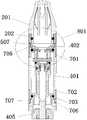
- FIG. 2is a schematic view showing a structure of an explosion connection of a preferred embodiment of the atomization assembly provided by the present invention
- FIG. 3is a cross-sectional structural view showing a preferred embodiment of the atomizing assembly provided by the present invention.
- FIG. 4is a schematic view showing a partial exploded connection structure of a preferred embodiment of the atomizing assembly provided by the present invention.
- Figure 5is a partially enlarged schematic view showing a preferred embodiment of the atomizing assembly shown in Figure 3;
- FIG. 6is a schematic view showing the overall structure of a preferred embodiment of the connecting sleeve included in the atomizing assembly shown in FIG. 3;
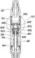
- FIG. 7is a cross-sectional structural view showing another preferred embodiment of the atomizing assembly provided by the present invention.
- Figure 8is a partially enlarged schematic view showing a preferred embodiment of the atomizing assembly shown in Figure 7;
- FIG. 9is a schematic overall structural view of a preferred embodiment of a coupling sleeve included in the atomizing assembly shown in FIG. 7;
- FIG. 10is a cross-sectional structural view showing another preferred embodiment of the atomizing assembly provided by the present invention.
- Figure 11is a partially enlarged schematic view showing a preferred embodiment of the atomizing assembly shown in Figure 10;
- FIG. 12is a schematic overall structural view of a preferred embodiment of a coupling sleeve included in the atomizing assembly shown in FIG. 10;
- Figure 13is a partial cross-sectional structural view showing a preferred embodiment of the atomizing assembly of the present invention.
- Figure 14is a top plan view showing a preferred embodiment of the blocking portion of the atomizing assembly shown in the embodiment
- FIG. 15is a schematic view showing a partial exploded connection structure of a preferred embodiment of the atomizing assembly provided by the present invention.
- Embodiment 1This embodiment describes in detail the specific structure of the atomizing component capable of avoiding user suction to the condensed soot oil:
- the atomizing assembly shown in this embodimentis used to form an electronic cigarette in combination with a battery assembly, and the atomizing assembly is used to atomize the smoke oil to form a smoke.
- FIG. 2is a schematic view showing a structure of an explosion connection of a preferred embodiment of the atomization assembly provided in the present invention
- FIG. 3is a view showing the atomization provided by the utility model.
- the atomization assemblyincludes: a suction nozzle 201 for sucking smoke, an atomization body 203 for atomizing the smoke oil to generate smoke, and a nozzle for connecting the suction nozzle 201 and the The connecting sleeve 202 of the atomizing body 203;
- the connecting sleeve 202 and the nozzle 201 and the atomizationrespectively
- the main body 203is detachably connected, thereby facilitating assembly of the atomizing assembly, and facilitating cleaning or replacing the suction nozzle 201 and the atomizing body 203.
- the connecting sleeve 202 and the suction nozzle 201 and the atomizing body 203are The specific manner of disassembling the connection is not limited, as long as the user can disassemble and connect at any time as needed.
- the connection sleeve 202can be detachably connected to the suction nozzle 201 and the atomizing body 203. , snap connection, magnet connection, plug connection and so on.
- FIG. 4is a schematic diagram of a partial exploded connection structure of a preferred embodiment of the atomizing assembly provided by the present invention. ;
- the atomization body 203includes a transparent oil storage jacket 401 having opposite first and second ends, wherein the degree of transparency and specific material of the oil storage jacket 401 is not limited in this embodiment, as long as the user can pass the
- the oil storage sleeve 401can view the remaining amount of smoke oil of the atomization assembly at any time, so that the user can estimate the length of time that the atomization assembly can be used according to the remaining amount of the smoke oil, and there is no shortage of remaining smoke oil. And the case of burning the atomizing component.
- the oil storage jacket 401is made of a non-metallic material such as PC (polycarbonate), PVC (polyvinyl chloride), or PET (polybutylene plastic) which can transmit light.
- the first end of the oil storage sleeveis provided with a first fastener 402 for fixing the connecting sleeve 202 to the oil storage sleeve 401, and the first The fastener 402 is also used to limit the radial expansion of the oil reservoir 401 to ensure a stable connection between the oil reservoir 401 and the connecting sleeve 202.
- a fuel filler port 4021is formed on one end surface of the first fastener 402.
- the fuel filler port 4021facilitates the user to add smoke oil, thereby prolonging the use duration of the atomization assembly.
- the oil storage jacket 401is internally provided with an atomizing core 403 for atomizing the smoke oil;
- An oil storage chamber 404(shown in FIG. 3) for storing the oil is formed between the atomization core 403 and the oil storage sleeve 401;
- the oil storage chamber 404is disposed in communication with the fuel filler port 4021 so that the oil added by the fuel filler port 4021 can be stored in the oil reservoir 404.
- the atomization core 403is inserted into the oil storage sleeve 401 to be assembled into an atomization assembly, thereby facilitating assembly and effectively improving the efficiency of assembling the atomization assembly.
- the liquid smoke oil stored in the oil storage chamber 404is taken as an example for description;
- a smoke passage 406is disposed along a longitudinal extension of the atomizing core 403. Specifically, the smoke passage 406 is communicated to an end surface of the atomizing core 403 facing the suction nozzle 201 so that the atomizing core 403 is inside. The smoke is circulated to the suction nozzle 201 via the smoke passage 406 to be sucked by the user.
- the atomizing bodyfurther includes an atomizing body electrode 405 electrically connected to the heating wire assembly 407;
- the heating wire assembly 407is electrically connected to the atomizing body electrode 405;
- the atomizing body electrode 405is disposed at an end of the atomizing core 403 away from the nozzle 201;
- the atomizing body electrode 405includes an outer electrode 4051, an inner electrode 4052 inserted in the outer electrode 4051, and an insulating ring 4053 disposed between the outer electrode 4051 and the inner electrode 4052.
- the heating wire assembly 407includes an oil guiding rope and a heating wire wound around the oil guiding rope; it can be understood that the heating wire assembly 407 can also be an oil guiding sleeve and sleeved on the heating wire assembly 407.
- the spiral heating wire or the like in the oil guiding sleeveis not limited, as long as the structure of the heating wire assembly can be atomized.
- the atomizing body electrode 405is not limited as long as it can electrically connect the heating wire to the battery rod assembly.
- the specific electrical connection manner of the heating wire assembly 407 and the atomizing body electrode 405is not limited, for example, electrical connection may be performed through a wire, for example, in the atomizing body electrode 405 and the A plurality of electrode assemblies electrically connected in sequence are disposed between the heating wire assemblies 407, and the electrode assemblies are electrically connected to the heating wire assembly 407 and the atomizing body electrode 405, respectively, and the electric heating is realized by the electrode assembly.
- This embodimentdoes not limit how the heating wire assembly 407 is specifically disposed in the smoke passage 406.
- One end of the connecting sleeve 202is inserted into the oil storage sleeve 401 from the end of the first fastener 402 where the fuel filler opening 4021 is disposed and detachably connected to the first fastener 402;
- connecting sleeve 202 and the first fastener 402are detachably connected is not limited in this embodiment.
- the outer circumferential surface of the connecting sleeve 202is sleeved with a first sealing ring 408 (shown in FIG. 4) elastically resisting the inner wall of the oil storage sleeve 401, and the first sealing ring 408 is used for isolating the
- the sleeve 202 and the oil reservoir 404are connected to prevent the smoke oil stored in the oil reservoir 404 from leaking through the connection sleeve 202.
- the connecting sleeve 202extends away from the end of the oil storage sleeve 401 to the outside of the first fastener 402 and is detachably connected to the suction nozzle 201.
- the connecting sleeve 202 and the nozzleare connected in this embodiment.
- the specific manner of the 201 detachable connectionis not limited.
- the connecting sleeve 202forms an annular blocking portion 409 near the end of the atomizing body 203, and the inner peripheral wall of the blocking portion 409 is disposed at an angle larger than the longitudinal direction of the connecting sleeve 202. 0 degree slope;
- FIG. 14is a schematic top view of a preferred embodiment of the blocking portion of the atomizing assembly shown in the embodiment.
- the end of the connecting sleeve 202 away from the nozzle 201is electrically connected to the smoke passage 406, so that the smoke flowing in the smoke passage 406 passes through the connecting sleeve.
- 202flows to the suction nozzle 201, and because the angle formed by the inner peripheral wall of the blocking portion 409 and the longitudinal direction of the connecting sleeve 202 is greater than a slope of 0 degrees, in the suction nozzle 201 or in the
- the smoky oil condensed in the connecting sleeve 202can be returned to the smoke passage 406 via the inclined surface formed by the inner peripheral wall of the blocking portion 409, and then returned to the heating wire assembly 407, so that the heating wire assembly 407 Re-atomizing the condensed smoke oil avoids the user's suction of the condensed smoke oil, and also improves the utilization efficiency of the smoke oil, effectively avoiding the waste of the smoke oil.
- the specific degree of the angle formed by the inner peripheral wall of the blocking portion 409 and the longitudinal direction of the connecting sleeve 202is not limited as long as the inner peripheral wall of the blocking portion 409 is inclined to make the condensed smoke.
- the oilcan be returned to the heating wire assembly 407 along the guide of the slope.
- the end of the atomizing core 403is disposed around the smoke outlet 4061 of the smoke passage 406 with a sealing member 410 elastically resisting the blocking portion 409;
- the smoke outlet 4061 of the smoke passage 406is opposite to the opening of the connecting sleeve 202 away from the end of the nozzle 201.
- the smoke passage 406is used to improve the circulation of the smoke.
- the vent 4061is disposed coaxially with the opening of the connecting sleeve 202 away from the end of the nozzle 201.
- the sealing member 410is configured to seal the oil storage chamber 404 to isolate the oil storage chamber 404 and the connecting sleeve 202 to prevent the oil stored in the oil storage chamber 404 from leaking to the connecting sleeve. 202 is internally used by the user.
- the nozzle 201is provided with a smoke exhausting hole 301, so that the smoke flowing through the smoke passage 406 and the connecting sleeve 202 in turn is sucked by the user through the exhaust hole 301. ;
- the end of the nozzle 201 connected to the connecting sleeve 202is provided with a condensed soot storage chamber 302 communicating with the connecting sleeve 202;
- the inclined surface of the inner peripheral wall of the blocking portion 409faces the condensed soot storage chamber 302;
- the condensed smoky oil storage chamber 302 shown in this embodimentthe condensed smoky oil 302 storage chamber and the smoke oil in the connecting sleeve 202 can pass the The inclined surface is introduced into the smoke outlet 4061 of the smoke passage 406, so that the oil flows to the heating wire assembly 407 via the smoke outlet 4061 of the smoke passage 406, thereby re-atomizing the heating wire assembly 407.
- the condensed smoke oileffectively improves the atomization efficiency of the smoke oil and effectively prevents the user from pumping the condensed smoke oil.
- An end edge of the exhaust hole 301 adjacent to the condensed soot storage chamber 302is provided with an oil-block 303 for preventing the smoke oil in the condensed oil storage space 302 from entering the exhaust hole 301. .
- the condensed sootcan be further stored in the condensed soot storage chamber 302 by the oil barrier 303 to prevent the user from pumping to the condensed soot.
- Embodiment 2This embodiment illustrates an example of a specific connection manner between the nozzle 201 and the connecting sleeve 202:
- connection manner between the nozzle 201 and the connecting sleeve 202is described as an example, which is not limited, as long as the nozzle 201 and the connecting sleeve 202 can be realized. It is detachable and connectable.
- FIG. 5is a partially enlarged schematic view showing a preferred embodiment of the atomizing assembly shown in FIG. 3, and FIG. 6 is included in the atomizing assembly shown in FIG.
- FIG. 5is an enlarged schematic view of a region 501 shown in FIG. 3;
- the nozzle 201is provided with a docking groove near the end of the connecting sleeve 202. 502, the two ends of the docking slot 502 are respectively connected to the condensed soot storage chamber 302 and the connecting sleeve 202, so that the nozzle 201 can be realized by the docking slot 502 and the connecting sleeve 202. Disassemble the connection;
- the cavity 503 of the condensed soot storage chamber 302is located in the docking groove 502;
- the cover 504 of the connecting sleeve 202has an area larger than the area of the cavity 503 of the condensed soot storage chamber 302, wherein the sleeve 504 is the connecting sleeve 202 facing the condensed soot storage chamber 302. Opening.
- the area of the sleeve 504is larger than the area of the cavity 503, so that the smoke oil located in the condensed soot storage chamber 302 can smoothly and completely pass through the cavity 503 and the The sleeve 504 flows into the connecting sleeve 202 to prevent the condensation condensate from being blocked.
- the area of the sleeve 504 of the connecting sleeve 202is smaller than the area of the bottom wall of the mating slot 502, so that the sleeve 504 of the connecting sleeve 202 can be inserted into the interior of the mating slot 502;
- the peripheral wall of the docking groove 502is provided with a third internal thread 505, and the outer peripheral wall of the end of the connecting sleeve 202 corresponding to the third internal thread 505 is provided with a third external thread 506, so that the connecting sleeve When the 202 is inserted into the end of the nozzle 201, the connecting sleeve 202 is screwed to the third internal thread 505 of the mating groove 502 by the third external thread 506;
- a friction groove 508is disposed on the outer peripheral wall of the connecting sleeve 202 between the first external thread 507 and the third external thread 506 .
- the first external thread 507is used to implement a detachable connection with the oil storage sleeve 401;
- the specific shape of the friction pattern 508is not limited in this embodiment.
- the advantage of using the friction rib 508is that the friction rib 508 can increase the friction between the user's hand and the connecting sleeve 202, thereby facilitating the user to connect the connecting sleeve 202 from the suction nozzle 201 and the The atomizing body is detached, and the user is allowed to assemble the connecting sleeve 202 to the suction nozzle 201 and the atomizing body, thereby improving the efficiency of disassembling or assembling the atomizing assembly.
- FIG. 7is a cross-sectional structural view showing another preferred embodiment of the atomizing assembly provided by the present invention
- FIG. 8is a schematic view of FIG. A partially enlarged schematic view of a preferred embodiment of the atomizing assembly
- FIG. 9is a schematic overall structural view of a preferred embodiment of the connecting sleeve included in the atomizing assembly shown in FIG. 7;
- FIG. 8is an enlarged schematic view of a region 801 shown in FIG. 7;
- the end of the nozzle 201 adjacent to the connecting sleeve 202is provided with a docking groove 802 , and the two ends of the docking slot 802 are respectively connected to the condensed soot storage chamber 302 and the connecting sleeve. 202 connected;
- the cavity 803 of the condensed soot storage chamber 302is located in the docking groove 802;
- the cover 804 of the connecting sleeve 202has an area larger than the area of the cavity 803 of the condensed soot storage chamber 302, wherein the sleeve 804 is the connecting sleeve 202 facing the condensed soot storage chamber 302. Opening.
- the area of the sleeve 804is larger than the area of the cavity 803, so that the smoke oil located in the condensed soot storage chamber 302 can smoothly and completely pass through the cavity 803 and the The sleeve 804 flows into the connecting sleeve 202 to prevent the condensation condensate from being blocked.
- the cover 804 of the connecting sleeve 202has an area larger than the area of the bottom wall of the mating slot 802, so that the sleeve 804 of the connecting sleeve 202 can be sleeved on the outer peripheral wall of the mating slot 802;
- the outer circumferential surface of the docking groove 802is provided with a concave third annular limiting step, so that when the connecting sleeve 202 is sleeved on the docking groove 802, the inner peripheral wall of the connecting sleeve 202 and the first The three annular limiting steps are abutted and interference fit, so that the connecting sleeve 202 can be fixedly disposed on the docking groove 802 to achieve stable connection between the connecting sleeve 202 and the nozzle 201.
- the outer peripheral wall of the connecting sleeve 202is provided with a friction pattern 808;
- the advantage of using the friction rib 808is that the friction rib 808 can increase the friction between the user's hand and the connecting sleeve 202, thereby facilitating the user to connect the connecting sleeve 202 from the suction nozzle 201 and the The atomizing body is detached, and the user is allowed to assemble the connecting sleeve 202 to the suction nozzle 201 and the atomizing body, thereby improving the efficiency of disassembling or assembling the atomizing assembly.
- FIG. 10is a cross-sectional structural view showing another preferred embodiment of the atomization assembly provided by the present invention
- FIG. 11is a schematic view of FIG. A partially enlarged schematic view of a preferred embodiment of the atomizing assembly
- FIG. 12is a schematic overall structural view of a preferred embodiment of the connecting sleeve included in the atomizing assembly shown in FIG.
- FIG. 11is an enlarged schematic view of the 1101 area shown in FIG. 10;
- the nozzle 201is disposed near the end of the connecting sleeve 202 with a docking slot 1102 , and the two ends of the docking slot 1102 and the condensed soot storage chamber 302 and the connecting sleeve respectively 202 connected;
- the cavity 1103 of the condensed soot storage chamber 302is located in the docking groove 1102;
- the area of the sleeve 1104 of the connecting sleeve 202is larger than the area of the cavity 1103 of the condensed soot storage chamber 302, wherein the sleeve 1104 is the connecting sleeve 202 facing the condensed soot storage chamber 302. Opening.
- the area of the sleeve 1104is larger than the area of the cavity 1103, so that the oil in the condensed soot storage chamber 302 can smoothly and completely pass through the cavity 1103 and the The sleeve 1104 flows into the connecting sleeve 202 to prevent the condensation of the smoky oil from being blocked.
- the sleeve 1104 of the connecting sleeve 202has an area larger than the bottom wall of the mating slot 1102, so that the sleeve 1104 of the connecting sleeve 202 can be sleeved on the outer peripheral wall of the mating slot 1102;
- the outer circumferential surface of the butt groove 1102is provided with a concave third annular limiting step, and the outer peripheral wall of the third annular limiting step is provided with a fourth external thread 1105;
- a fourth internal thread 1106is disposed on the inner peripheral wall of the connecting sleeve 202 corresponding to the fourth external thread 1105, so that when the connecting sleeve 202 is sleeved on the third annular limiting step, the connecting sleeve 202 passes The fourth internal thread 1106 is screwed to the fourth external thread 1105 of the docking groove 1102;
- the outer peripheral wall of the connecting sleeve 202is provided with a rubbing 1107.
- the advantage of using the frictional pattern 1107is that the frictional pattern 1107 can increase the friction between the user's hand and the connecting sleeve 202, thereby facilitating the user to connect the connecting sleeve 202 from the suction nozzle 201 and the The atomizing body is detached, and the user is allowed to assemble the connecting sleeve 202 to the suction nozzle 201 and the atomizing body, thereby improving the efficiency of disassembling or assembling the atomizing assembly.
- Embodiment 3This embodiment further describes the specific structure of the atomization component in further detail:
- the outer peripheral surface of the first end of the oil storage sleeve 401is provided with a concave first annular limiting step 701, and the outer peripheral surface of the second end of the oil storage sleeve 401 is disposed.
- a second annular limit step 702having a concave shape
- the first fastener 402is disposed on the first annular limiting step 701, and an interference fit between the first fastener 402 and the first annular limiting step 701 is performed;
- a second fastener 703is disposed on the second annular limiting step 702, and an interference fit between the second fastener 703 and the second annular limiting step 702 is performed;
- the outer peripheral wall of the connecting sleeve 202 inserted into the end of the first fastener 402is provided with a first external thread 507, the first fastener 402 and the first outer 507 pairs of threads
- a first internal thread 705is disposed at a position such that the coupling sleeve 202 is threadedly coupled to the first internal thread 705 of the first fastener 402 by the first external thread 507.
- the atomizing body electrode 405is inserted and fixed in the second end of the oil storage jacket 401;
- the second fastener 703is disposed near the inner peripheral wall of the atomizing body electrode 405 with a second internal thread 706, and the atomizing body electrode 405 is adjacent to the outer peripheral wall of the second internal thread 706.
- a second external thread 707is provided to thread the atomizing body electrode 405 through the second external thread 707 with the second internal thread 706 of the second fastener 703.
- the inner diameter of the blocking portion 905is sequentially decreased in the direction close to the atomizing body 203;
- the present embodimentis exemplified by taking the example shown in FIG. 5, FIG. 8 and FIG. 11 as an example, and is not limited thereto, as long as the smoke oil in the connecting sleeve 202 is returned to the heating wire assembly 407, for example, As can be seen from Fig. 13, the inner wall of the blocking portion 1301 has a circular arc shape.
- the specific structure of the blocking portion 905 shown in FIG. 5, FIG. 8 and FIG. 11is taken as an example for description, and preferably, the inner peripheral wall of the blocking portion 905 shown in this embodiment is
- the longitudinal direction of the connecting sleeve 202may be any angle between 30° and 70°, preferably 45°.
- the inner peripheral wall 907 of the connecting portion 906 of the connecting sleeve 202 and the blocking portion 905has a rounded structure
- the connecting portion 906is a position where the connecting sleeve 202 extends to the outside of the first fastener 402;
- the inner side wall 908 of the blocking portion 905 near the end of the atomizing body 203has a rounded structure.
- the inner peripheral wall of the connecting sleeve 202has a smooth slope.
- the inner peripheral wall of the connecting sleeve 202preferably has a smoothness ranging from Ra0.1 to Ra0.4.
- the inner peripheral wall 907 of the connecting portion 906 connected to the blocking portion 905has a rounded structure, and the inner side wall 908 of the blocking portion 905 near the end of the atomizing body 203 has a rounded structure.
- the oil in the condensed soot storage chamber 302 and the connecting sleeve 202can be smoothly returned to the heating wire assembly 407 to prevent the smoky oil from condensing on the inner side wall of the connecting sleeve 202 to be used by the user. Smoking.
- FIG. 15is a schematic view of a partial exploded connection structure of a preferred embodiment of the atomization assembly provided by the present invention.
- the atomizing core 403further includes an atomizing seat 4031;
- the heating wire assembly 407includes an oil guiding member 4032 mounted on the atomizing seat 4031 and an electric heating wire 4033 wound on the oil guiding member 4032. Both ends of the heating wire 4033 and the atomizing The main electrode 405 is electrically connected to the main electrode 405. Specifically, one end of the heating wire 4033 is electrically connected to the outer electrode 4051, and the other end of the heating wire 4033 is electrically connected to the inner electrode 4052.
- the atomization seat 4031includes a first atomization sub-seat 4034 and a second atomization sub-seat 4035.
- the first atomization sub-seat 4034is inserted and fixed to the smoke channel 406 near the connection sleeve 202.
- a slot 4036(shown in FIG. 15) is defined in the sidewall of the first atomizer sub-seat 4034 adjacent to the end of the connecting sleeve 202.
- the oil guiding member 4032is mounted on the slot 4036. And both ends of the oil guiding member 4032 are inserted into the oil reservoir 404 via the slot 4036.
- the second atomizing sub-seat 4035is inserted into the end of the first atomizing seat 4034 near the connecting sleeve 202, so that the heating wire 4033 is located inside the second atomizing sub-seat 4035.
- Inside the chamber 4037(as shown in Figure 10);
- the second atomizing sub-seat 4035is adjacent to the end surface of the connecting sleeve 202 and is provided with the smoke outlet 4061 (as shown in FIG. 3, FIG. 10 and FIG. 15);
- the first atomizing sub-seat 4034is adjacent to the end surface of the atomizing body electrode 405 and has a vent hole 4039 (as shown in FIG. 10), and the atomizing chamber 4037 and the venting port 4061 and the The venting hole 4039 is turned on, and the atomizing chamber 4037 is electrically connected to the inner cavity of the connecting sleeve 202 via the venting port 4061, so that the smoky oil in the connecting sleeve 202 is sequentially passed through the connecting sleeve 202. And the smoke outlet 4061 is returned to the heating wire 4033 located in the atomization chamber 4037, so that the condensed smoke oil can be atomized again, and the condensed smoke oil is prevented from being sucked by the user.
- a second sealing ringis disposed between the first atomizing sub-seat 4034 and the smoke passage 406. 4040, thereby effectively preventing the smoke oil in the oil storage chamber 404 from leaking into the smoke passage 406 via the first atomizing sub-seat 4034;
- a third sealing ring 4041is disposed between the atomizing core 403 and the oil storage sleeve 401 to effectively prevent the oil in the oil reservoir 404 from leaking into the interior of the atomizing core 403;
- the atomization seat 4031is made of a metal material or a ceramic material, and the specific material is not limited in this embodiment.
- the specific shape of the slot 4036 in the side wall of the end portion of the first atomizing sub-seat 4034 adjacent to the connecting sleeve 202is not limited, as long as the guiding unit can be firmly fixed.
- the oil member 4032can be, for example, the slot 4036 of the first atomizing sub-seat 4034 is two oppositely disposed U-shaped recesses.
- the end of the atomization core 403 away from the connection sleeve 202is inserted.
- the outer electrode 4051is inside, and the end of the atomizing core 403 away from the connecting sleeve 202 is interference-fitted with the outer electrode 4051.
- the present inventionalso provides an electronic cigarette comprising a detachably connected atomizing component and a battery component, and the battery component is used for powering the atomizing component to atomize the atomizing component
- the oilis used to form a smoke that can be used by the user, and the battery assembly is not described in the prior art.
- the specific structure of the atomization componentrefer to the first embodiment and the third embodiment, and details are not described herein.
Landscapes
- Electrostatic Spraying Apparatus (AREA)
- Disinfection, Sterilisation Or Deodorisation Of Air (AREA)
Abstract
Description
Translated fromChinese本实用新型涉及电子烟技术领域,特别涉及一种雾化组件以及电子烟。The utility model relates to the technical field of electronic cigarettes, in particular to an atomization assembly and an electronic cigarette.
现有技术的雾化组件的结构请参见图1所示,由图1可知,该雾化组件用以雾化烟油以形成可供用户吸食的烟雾,具体的设置方式为雾化套105内部设置有玻纤管102,所述玻纤管102外部围绕包覆设置有用于存储烟油的储油棉101。所述玻纤管102内部设置有玻纤线103,所述玻纤线103的端部穿过所述玻纤管102,并插入所述储油棉101,且所述玻纤线103上缠绕设置有用于雾化烟油的呈柱状的电热丝104。通过所述玻纤管102和所述玻纤线103以使得所述储油棉101内的烟油可传导到所述电热丝104上,以使所述电热丝104雾化烟油以形成烟雾,以使得用户通过吸嘴106吸食烟雾。The structure of the prior art atomizing assembly is shown in FIG. 1. As can be seen from FIG. 1, the atomizing assembly is used to atomize the smoke oil to form a smoke for the user to take. The specific arrangement is the inside of the
由图1所示可知,现有技术中的吸嘴106与设置有所述电热丝104的所述玻纤管102之间通过一空腔107进行导通,进而使得烟雾依次经由所述玻纤管102和所述空腔107导通至所述吸嘴106以被用户吸食,但是烟雾在空腔107内极容易冷凝,而使得空腔107内冷凝的烟油被用户通过所述吸嘴106吸食,从而极大的影响了用户抽吸烟雾的口感以及身体健康。It can be seen from FIG. 1 that the
实用新型内容Utility model content
本实用新型提供了一种雾化组件以及电子烟。The utility model provides an atomization assembly and an electronic cigarette.
一种雾化组件,用于与电池组件组合形成电子烟,其中,所述雾化组件包括吸嘴、连接套和雾化主体;An atomizing assembly for forming an electronic cigarette in combination with a battery assembly, wherein the atomizing assembly comprises a suction nozzle, a connecting sleeve and an atomizing body;
所述雾化主体包括具有相对的第一端和第二端的透明储油套,所述储油套的第一端外套设有第一紧固件,所述第一紧固件的一端端面上形成有加油口,所述储油套内插设有用于雾化烟油的雾化芯,所述雾化芯与所述储油套之间形成有与所述加油口相连通的用于存储烟油的储油腔,沿所述雾化芯的纵向延伸设置有烟雾通道,所述烟雾通道连通至所述雾化芯面向所述吸嘴的端面,设置在所述烟雾通道内的用于雾化烟油的电热丝组件,所述雾化主体还包括与所述电热丝组件电连接的雾化主体电极,且所述雾化主体电极设置在所述雾化芯远离所述吸嘴的一端;The atomizing body includes a transparent oil storage sleeve having opposite first ends and second ends, and the first end of the oil storage sleeve is provided with a first fastener, and one end surface of the first fastener is Forming a fueling port, the oil storage sleeve is internally provided with an atomizing core for atomizing the oil, and the atomizing core and the oil storage sleeve are formed with a communication port connected to the oil filling port for storing An oil storage chamber of the smoke oil, a smoke passage is disposed along a longitudinal extension of the atomization core, and the smoke passage is connected to an end surface of the atomizing core facing the nozzle, and is disposed in the smoke passage for An electric heating wire assembly for atomizing the smoke oil, the atomizing body further comprisingAn atomizing body electrode electrically connected to the heating wire assembly, and the atomizing body electrode is disposed at an end of the atomizing core away from the nozzle;
所述连接套的一端从所述第一紧固件设置有所述加油口的端部插入所述储油套内并与所述第一紧固件可拆卸连接,所述连接套的外周面上套设有与所述储油套的内壁弹性抵持的第一密封圈,所述连接套远离所述储油套的一端延伸至所述第一紧固件外并与所述吸嘴可拆卸连接;所述吸嘴设置有排烟孔,所述吸嘴与所述连接套相连的一端设置有与所述连接套相连通的冷凝烟油存储腔,所述排烟孔与所述冷凝烟油存储腔相邻的一端端缘设置有用于阻止所述冷凝烟油存储空间内的烟油进入所述排烟孔的阻油柱;One end of the connecting sleeve is inserted into the oil storage sleeve from an end of the first fastener provided with the fuel filler opening and is detachably connected to the first fastener, and the outer circumferential surface of the connecting sleeve The upper sleeve is provided with a first sealing ring elastically resisting the inner wall of the oil storage sleeve, and the connecting sleeve extends away from the one end of the oil storage sleeve to the outside of the first fastener and is compatible with the suction nozzle Disassembling the connection; the nozzle is provided with a smoke exhausting hole, and one end of the suction nozzle connected to the connecting sleeve is provided with a condensed soot storage cavity communicating with the connecting sleeve, the exhausting hole and the condensation An oil gas column for preventing the smoke oil in the condensed soot storage space from entering the smoke exhaust hole is disposed at an adjacent end edge of the oil storage chamber;
所述连接套一端端部形成有呈环形的阻挡部,且所述阻挡部的内周壁设置有与所述连接套的纵向形成的夹角大于0度的斜面,所述斜面面向所述冷凝烟油存储腔设置,以使在所述雾化组件竖直放置时所述冷凝烟油存储腔及所述连接套内的烟油能够通过所述斜面导入所述烟雾通道的出烟口中,所述雾化芯的端部环绕所述烟雾通道的出烟口设置有与所述阻挡部弹性抵持的密封件,所述密封件用于密封所述储油腔。An end portion of the connecting sleeve is formed with an annular blocking portion, and an inner peripheral wall of the blocking portion is provided with a slope formed at an angle greater than 0 degrees with a longitudinal direction of the connecting sleeve, the inclined surface facing the condensation smoke The oil storage chamber is disposed such that the condensed soot storage chamber and the smoke oil in the connecting sleeve can be introduced into the smoke outlet of the smoke passage through the inclined surface when the atomizing assembly is vertically placed, An end of the atomizing core is provided around the smoke outlet of the smoke passage with a seal elastically resisting the blocking portion, the seal being for sealing the oil reservoir.
优选的,所述吸嘴靠近所述连接套的端部设置有对接槽,所述对接槽的两端分别与所述冷凝烟油存储腔及所述连接套相连通;Preferably, the nozzle is provided with a docking groove near the end of the connecting sleeve, and two ends of the docking slot are respectively connected with the condensed soot storage chamber and the connecting sleeve;
所述冷凝烟油存储腔的腔口位于所述对接槽内,所述连接套的套口的面积大于所述冷凝烟油存储腔的腔口的面积,所述套口为所述连接套面向所述冷凝烟油存储腔的开口。The cavity of the condensed soot storage chamber is located in the docking groove, the area of the sleeve of the connecting sleeve is larger than the area of the cavity of the condensed soot storage chamber, and the sleeve is facing the connecting sleeve The condensed soot reservoir has an opening in the storage chamber.
优选的,所述储油套的第一端外周面设置有内凹的的第一环形限位台阶,所述储油套的第二端外周面设置有内凹的的第二环形限位台阶,套设在所述第一环形限位台阶上设置有所述第一紧固件,且所述第一紧固件与所述第一环形限位台阶之间过盈配合,套设在所述第二环形限位台阶上设置有第二紧固件,且所述第二紧固件与所述第二环形限位台阶之间过盈配合;Preferably, the outer peripheral surface of the first end of the oil storage sleeve is provided with a concave first annular limiting step, and the outer peripheral surface of the second end of the oil storage sleeve is provided with a concave second annular limiting step Providing the first fastener on the first annular limiting step, and the interference fit between the first fastener and the first annular limiting step is set in the a second fastener is disposed on the second annular limiting step, and an interference fit is formed between the second fastener and the second annular limiting step;
所述连接套插入所述第一紧固件端部的外周壁设置有第一外螺纹,所述第一紧固件与所述第一外螺纹对应位置设置有第一内螺纹,以使所述连接套通过所述第一外螺纹与所述第一紧固件的所述第一内螺纹螺纹连接;The outer peripheral wall of the connecting sleeve inserted into the end of the first fastener is provided with a first external thread, and the first fastener is disposed with a first internal thread corresponding to the first external thread, so as to The connecting sleeve is screwed to the first internal thread of the first fastener by the first external thread;
所述雾化主体电极插设固定在所述储油套的第二端内,所述第二紧固件靠近所述雾化主体电极的内周壁设置有第二内螺纹,所述雾化主体电极与所述第二内螺纹对应的外周壁上设置有第二外螺纹,以使所述雾化主体电极通过所述第二外螺纹与所述第二紧固件的所述第二内螺纹螺纹连接。The atomizing body electrode is inserted and fixed in the second end of the oil storage sleeve, and the second fastener isa second internal thread is disposed on the inner peripheral wall of the atomizing body electrode, and a second external thread is disposed on the outer peripheral wall of the atomizing body electrode corresponding to the second internal thread, so that the atomizing body electrode The second internal thread of the second fastener is threaded by the second external thread.
优选的,所述连接套的套口的面积小于所述对接槽底壁的面积;Preferably, the area of the sleeve of the connecting sleeve is smaller than the area of the bottom wall of the docking groove;
所述对接槽的周壁设置有第三内螺纹,所述连接套的端部与所述第三内螺纹对应的外周壁上设置有第三外螺纹,以使所述连接套插设在所述吸嘴的端部内时,所述连接套通过所述第三外螺纹与所述对接槽的所述第三内螺纹螺纹连接;The peripheral wall of the docking groove is provided with a third internal thread, and the outer peripheral wall of the end of the connecting sleeve corresponding to the third internal thread is provided with a third external thread, so that the connecting sleeve is inserted in the When the end of the nozzle is inside, the connecting sleeve is screwed to the third internal thread of the mating groove by the third external thread;
所述连接套的外周壁上,且位于所述第一外螺纹和所述第三外螺纹之间设置有摩擦纹。A frictional pattern is disposed on the outer peripheral wall of the connecting sleeve between the first external thread and the third external thread.
优选的,所述连接套的套口的面积大于所述对接槽底壁的面积;Preferably, the area of the sleeve of the connecting sleeve is larger than the area of the bottom wall of the docking groove;
所述对接槽外周面设置有内凹的第三环形限位台阶,以使所述连接套套设在所述对接槽上时,所述连接套的内周壁与所述第三环形限位台阶相抵持且过盈配合;The outer circumferential surface of the docking groove is provided with a concave third annular limiting step, so that the inner circumferential wall of the connecting sleeve is offset from the third annular limiting step when the connecting sleeve is disposed on the mating groove Hold and fit;
所述连接套的外周壁设置有摩擦纹。The outer peripheral wall of the connecting sleeve is provided with a rubbing pattern.
优选的,所述连接套的套口的面积大于所述对接槽底壁的面积;Preferably, the area of the sleeve of the connecting sleeve is larger than the area of the bottom wall of the docking groove;
所述对接槽外周面设置有内凹的第三环形限位台阶,且所述第三环形限位台阶的外周壁设置有第四外螺纹;The outer peripheral surface of the docking groove is provided with a concave third annular limiting step, and the outer peripheral wall of the third annular limiting step is provided with a fourth external thread;
所连接套与所述第四外螺纹对应的内周壁上设置有第四内螺纹,以使所述连接套套设在第三环形限位台阶上时,所述连接套通过所述第四内螺纹与所述对接槽的所述第四外螺纹螺纹连接;a fourth internal thread is disposed on the inner peripheral wall of the connecting sleeve corresponding to the fourth external thread, so that the connecting sleeve passes the fourth internal thread when the connecting sleeve is disposed on the third annular limiting step Threaded with the fourth external thread of the docking groove;
所述连接套的外周壁设置有摩擦纹。The outer peripheral wall of the connecting sleeve is provided with a rubbing pattern.
优选的,Preferably,
所述阻挡部的内径沿靠近所述雾化主体的方向依次递减;The inner diameter of the blocking portion is sequentially decreased in a direction close to the atomizing body;
或,or,
所述阻挡部的内壁呈圆弧形。The inner wall of the blocking portion has a circular arc shape.
优选的,所述连接套的连接部与所述阻挡部相连接的内周壁呈倒圆角结构,所述连接部为所述连接套延伸至所述第一紧固件外的位置;Preferably, the inner peripheral wall of the connecting portion of the connecting sleeve and the blocking portion has a rounded structure, and the connecting portion is a position where the connecting sleeve extends to the outside of the first fastener;
所述阻挡部靠近所述雾化主体的端部的内侧壁呈倒圆角结构。The inner side wall of the blocking portion near the end of the atomizing body has a rounded structure.
优选的,所述雾化芯还包括雾化座,所述电热丝组件包括架设在所述雾化座上的导油件和缠绕设置在所述导油件上的电热丝,所述电热丝的两端与所述雾化主体电极电连接;Preferably, the atomizing core further comprises an atomizing seat, the electric heating wire assembly comprises an oil guiding member mounted on the atomizing seat and a heating wire wound on the oil guiding member, the heating wire Both ends are electrically connected to the atomizing body electrode;
所述雾化座包括第一雾化子座和第二雾化子座,所述第一雾化子座插设固定在所述烟雾通道靠近所述连接套的端部,且所述第一雾化子座与所述烟雾通道之间过盈配合,所述第一雾化子座靠近所述连接套的端部的侧壁上开设有插槽,所述导油件架设在所述插槽上,且所述导油件的两端经由所述插槽插入所述储油腔内;The atomizing seat includes a first atomizing sub-seat and a second atomizing sub-seat, the first atomizing sub-seat is inserted and fixed at an end of the smoke channel close to the connecting sleeve, and the first An interference fit between the atomizing sub-seat and the smoke passage, the first atomizing sub-seat is provided with a slot on a side wall of the end of the connecting sleeve, and the oil guiding member is mounted on the insertion a slot, and both ends of the oil guiding member are inserted into the oil reservoir via the slot;
所述第二雾化子座插设在所述第一雾化座靠近所述连接套的端部内,以使所述电热丝位于所述第二雾化子座内部的雾化腔内;The second atomizing sub-seat is inserted into the end of the first atomizing seat adjacent to the connecting sleeve, so that the heating wire is located in the atomizing cavity inside the second atomizing sub-seat;
所述第二雾化子座靠近所述连接套的端面开设有第一通气孔,所述第一雾化子座靠近所述雾化主体电极的端面开始有第二通气孔,且所述雾化腔分别和所述第一通气孔和所述第二通气孔导通,且所述雾化腔经由所述第一通气孔与所述连接套的内腔导通,以使所述连接套内的烟油依次经由所述连接套和所述第一通气孔回流至位于所述雾化腔内的所述电热丝上。a first vent hole is defined in an end surface of the second atomizing sub-seat adjacent to the connecting sleeve, and a second venting hole is formed in the first atomizing sub-seat near an end surface of the atomizing body electrode, and the fog The clogging chamber is respectively electrically connected to the first venting hole and the second venting hole, and the atomizing chamber is electrically connected to the inner cavity of the connecting sleeve via the first venting hole, so that the connecting sleeve The internal smoky oil is sequentially returned to the heating wire located in the atomization chamber via the connecting sleeve and the first vent hole.
优选的,所述第一雾化子座和所述烟雾通道之间设置有第二密封圈;Preferably, a second sealing ring is disposed between the first atomizing sub-seat and the smoke passage;
所述雾化芯和所述储油套之间设置有第三密封圈。A third sealing ring is disposed between the atomizing core and the oil storage jacket.
优选的,所述雾化座由金属材质制成或由陶瓷材质制成。Preferably, the atomization seat is made of metal material or made of ceramic material.
优选的,所述第一雾化子座的所述插槽为两个相对设置的U型凹部。Preferably, the slot of the first atomizing sub-seat is two oppositely disposed U-shaped recesses.
优选的,所述雾化主体电极包括外电极,插设在所述外电极内的内电极,以使设置在所述外电极和所述内电极之间的绝缘环;所述电热丝的一端与所述外电极电连接,所述电热丝的另一端与所述内电极电连接;Preferably, the atomizing body electrode includes an outer electrode, an inner electrode interposed in the outer electrode, such that an insulating ring disposed between the outer electrode and the inner electrode; one end of the heating wire Electrically connected to the outer electrode, the other end of the heating wire is electrically connected to the inner electrode;
所述雾化芯远离所述连接套的端部插设在所述外电极内,且所述雾化芯远离所述连接套的端部与所述外电极过盈配合。The end of the atomizing core away from the connecting sleeve is inserted into the outer electrode, and the end of the atomizing core away from the connecting sleeve is interference-fitted with the outer electrode.
一种电子烟,包括相互连接的电池组件和雾化组件,其中,所述雾化组件为上述任一项所述的雾化组件。An electronic cigarette comprising an interconnected battery assembly and an atomizing assembly, wherein the atomizing assembly is the atomizing assembly of any of the above.
本实用新型所提供的雾化组件包括吸嘴、连接套和雾化主体,优势在于,由于所述雾化主体的储油套为透明的,便于用户随时查看该雾化组件的剩余的烟油量,且所述储油套的第一端外套设有第一紧固件,以使连接套和所述储油套之间稳固连接,且所述第一紧固件还可限制所述储油套径向膨胀,以使所述储油套和所述连接套涨紧配合固定连接,因而较好地避免储油套从所述连接套上脱落,阻止位于储油套内的烟油从所述储油套和所述连接套之间泄露出来,较好地避免烟油粘到用户,且所述连接套部形成呈环形的阻挡部,且所述阻挡部的内周壁与所述连接套的纵向形成的夹角大于0度的斜面,进而使得冷凝的烟油能够顺着阻挡部内周壁所形成的斜面回流至所述雾化主体以重新进行雾化,避免了冷凝的烟油被用户吸食,提升了用户抽吸电子烟过程中的口感,提升了烟油的利用效率,从而有效的延长了电子烟的使用时间;此外,通过所述连接套密封所述加油口,并分别与所述吸嘴及所述雾化主体可拆卸连接,因而不仅较好地阻止储油腔内的烟油朝所述吸嘴方向泄露,较方便的清理所述吸嘴中冷凝烟油存储腔的烟油,而且吸嘴与所述连接套之间广阔的区域进一步的较好地阻止用户吸食到烟油。The atomization assembly provided by the utility model comprises a nozzle, a connecting sleeve and an atomizing body. The advantage is that since the oil storage sleeve of the atomizing body is transparent, the user can conveniently view the remaining smoke oil of the atomizing assembly at any time. And the first end of the oil storage sleeve is provided with a first fastener to make the connecting sleeve and the oil storageThe first fastener can also restrain the radial expansion of the oil storage sleeve, so that the oil storage sleeve and the connecting sleeve are tightly coupled with the fixed connection, thereby better avoiding storage The oil jacket is detached from the connecting sleeve, and the smoke oil located in the oil storage sleeve is prevented from leaking out between the oil storage sleeve and the connecting sleeve, so that the smoke oil is better prevented from sticking to the user, and the connecting sleeve is The portion forms an annular blocking portion, and the inner peripheral wall of the blocking portion forms an inclined angle with the longitudinal direction of the connecting sleeve greater than 0 degrees, thereby enabling the condensed soot to flow back along the inclined surface formed by the inner peripheral wall of the blocking portion. The atomization body is re- atomized to prevent the condensed smoke oil from being sucked by the user, thereby improving the taste of the user during the process of smoking the electronic cigarette, thereby improving the utilization efficiency of the smoke oil, thereby effectively extending the electronic cigarette. In addition, the fuel filler is sealed by the connecting sleeve and detachably connected to the nozzle and the atomizing body, respectively, thereby not only preventing the smoke in the oil reservoir from being sucked toward the suction Leaked in the direction of the mouth, more convenient to clear The smoke oil of the smoke storage chamber is condensed in the nozzle, and a wide area between the nozzle and the connecting sleeve further better prevents the user from smoking the smoke oil.
图1为现有技术中雾化组件的剖面结构示意图;1 is a schematic cross-sectional structural view of an atomizing assembly in the prior art;
图2所示为本实用新型所提供的雾化组件的一种较佳实施例爆炸连接结构示意图;2 is a schematic view showing a structure of an explosion connection of a preferred embodiment of the atomization assembly provided by the present invention;
图3所示为本实用新型所提供的雾化组件的一种较佳实施例剖面结构示意图;3 is a cross-sectional structural view showing a preferred embodiment of the atomizing assembly provided by the present invention;
图4所示为本实用新型所提供的雾化组件的一种较佳实施例局部爆炸连接结构示意图;4 is a schematic view showing a partial exploded connection structure of a preferred embodiment of the atomizing assembly provided by the present invention;
图5为图3所示的雾化组件的一种较佳实施例局部放大示意图;Figure 5 is a partially enlarged schematic view showing a preferred embodiment of the atomizing assembly shown in Figure 3;
图6为图3所示的雾化组件所包含的连接套的一种较佳实施例整体结构示意图;6 is a schematic view showing the overall structure of a preferred embodiment of the connecting sleeve included in the atomizing assembly shown in FIG. 3;
图7所示为本实用新型所提供的雾化组件的另一种较佳实施例剖面结构示意图;7 is a cross-sectional structural view showing another preferred embodiment of the atomizing assembly provided by the present invention;
图8为图7所示的雾化组件的一种较佳实施例局部放大示意图;Figure 8 is a partially enlarged schematic view showing a preferred embodiment of the atomizing assembly shown in Figure 7;
图9为图7所示的雾化组件所包含的连接套的一种较佳实施例整体结构示意图;9 is a schematic overall structural view of a preferred embodiment of a coupling sleeve included in the atomizing assembly shown in FIG. 7;
图10所示为本实用新型所提供的雾化组件的另一种较佳实施例剖面结构示意图;FIG. 10 is a cross-sectional structural view showing another preferred embodiment of the atomizing assembly provided by the present invention; FIG.
图11为图10所示的雾化组件的一种较佳实施例局部放大示意图;Figure 11 is a partially enlarged schematic view showing a preferred embodiment of the atomizing assembly shown in Figure 10;
图12为图10所示的雾化组件所包含的连接套的一种较佳实施例整体结构示意图;12 is a schematic overall structural view of a preferred embodiment of a coupling sleeve included in the atomizing assembly shown in FIG. 10;
图13所示为本实用新型所提供的雾化组件的一种较佳实施例局部剖面结构示意图;Figure 13 is a partial cross-sectional structural view showing a preferred embodiment of the atomizing assembly of the present invention;
图14为本实施例所示的雾化组件的阻挡部的一种较佳实施例俯视结构示意图;Figure 14 is a top plan view showing a preferred embodiment of the blocking portion of the atomizing assembly shown in the embodiment;
图15所示为本实用新型所提供的雾化组件的一种较佳实施例局部爆炸连接结构示意图。FIG. 15 is a schematic view showing a partial exploded connection structure of a preferred embodiment of the atomizing assembly provided by the present invention.
下面将结合本实用新型实施例中的附图,对本实用新型实施例中的技术方案进行清楚、完整地描述,显然,所描述的实施例仅仅是本实用新型一部分实施例,而不是全部的实施例。基于本实用新型中的实施例,本领域普通技术人员在没有做出创造性劳动前提下所获得的所有其他实施例,都属于本实用新型保护的范围。The technical solutions in the embodiments of the present invention will be clearly and completely described in conjunction with the drawings in the embodiments of the present invention. It is obvious that the described embodiments are only a part of the embodiments of the present invention, and not all of the embodiments. example. All other embodiments obtained by those skilled in the art based on the embodiments of the present invention without creative efforts are within the scope of the present invention.
实施例一,本实施例对能够避免用户抽吸到冷凝烟油的雾化组件的具体结构进行详细说明:Embodiment 1 This embodiment describes in detail the specific structure of the atomizing component capable of avoiding user suction to the condensed soot oil:
本实施例所示的雾化组件用于与电池组件组合形成电子烟,且所述雾化组件用于雾化烟油以形成烟雾。The atomizing assembly shown in this embodiment is used to form an electronic cigarette in combination with a battery assembly, and the atomizing assembly is used to atomize the smoke oil to form a smoke.
首先请参见图2和图3所示,图2所示为本实用新型所提供的雾化组件的一种较佳实施例爆炸连接结构示意图,图3所示为本实用新型所提供的雾化组件的一种较佳实施例剖面结构示意图;Referring first to FIG. 2 and FIG. 3, FIG. 2 is a schematic view showing a structure of an explosion connection of a preferred embodiment of the atomization assembly provided in the present invention, and FIG. 3 is a view showing the atomization provided by the utility model. A schematic cross-sectional structural view of a preferred embodiment of the assembly;
由图2所示可知,所述雾化组件包括:用于抽吸烟雾的吸嘴201、用于雾化烟油以生成烟雾的雾化主体203以及用于连接所述吸嘴201和所述雾化主体203的连接套202;As shown in FIG. 2, the atomization assembly includes: a
由图2和图3所示可知,所述连接套202分别与所述吸嘴201和所述雾化主体203可拆卸连接,进而便于装配雾化组件,以及便于清洗或更换吸嘴201以及雾化主体203,本实施例对所述连接套202与所述吸嘴201和所述雾化主体203可拆卸连接的具体方式不做限定,只要用户根据需要可随时进行拆卸和连接即可,例如所述连接套202与所述吸嘴201和所述雾化主体203可拆卸连接的方式可为螺纹连接,卡扣连接,磁铁连接,插拔连接等等。As can be seen from FIG. 2 and FIG. 3, the connecting
以下结合图3和图4所示对所述雾化主体的具体结构进行详细说明,其中,图4所示为本实用新型所提供的雾化组件的一种较佳实施例局部爆炸连接结构示意图;The specific structure of the atomizing body is described in detail below with reference to FIG. 3 and FIG. 4 , wherein FIG. 4 is a schematic diagram of a partial exploded connection structure of a preferred embodiment of the atomizing assembly provided by the present invention. ;
所述雾化主体203包括具有相对的第一端和第二端的透明储油套401,其中,本实施例对所述储油套401的透明程度以及具体材质不作限定,只要用户能够通过所述储油套401随时查看该雾化组件的剩余的烟油量即可,从而使得用户根据剩余的烟油量能够预估该雾化组件还能够使用的时长,不会出现因剩余烟油量不足而烧坏雾化组件的情况。优选的,该储油套401由能够透光的PC(聚碳酸酯)、PVC(聚氯乙烯)、PET(聚对苯二甲酸类塑料)等非金属材料制成。The
所述储油套的第一端外套设有第一紧固件402,所述第一紧固件402用于将所述连接套202固定在所述储油套401上,且所述第一紧固件402还用于限制所述储油套401径向膨胀,以保障所述储油套401和所述连接套202之间的稳定连接。The first end of the oil storage sleeve is provided with a
如图4所示,所述第一紧固件402的一端端面上形成有加油口4021,通过所述加油口4021便于用户添加烟油,进而延长雾化组件的使用时长。As shown in FIG. 4, a
进一步的,所述储油套401内插设有用于雾化烟油的雾化芯403;Further, the
所述雾化芯403与所述储油套401之间形成有用于存储烟油的储油腔404(如图3所示);An oil storage chamber 404 (shown in FIG. 3) for storing the oil is formed between the
具体的,所述储油腔404与所述加油口4021相连通设置,以使通过所述加油口4021所添加的烟油能够存储在所述储油腔404内。Specifically, the
本实施例中,将所述雾化芯403插设入所述储油套401内即可组装成雾化组件,从而便于装配,有效的提升了装配雾化组件的效率。In this embodiment, the
本实施例中,为提升所述储油腔404内部可存储的烟油量,以有效的提升所述雾化组件的使用时长,则本实施例中,以所述储油腔404内部所存储的为液态的烟油为例进行说明;In this embodiment, in order to increase the amount of soot oil that can be stored inside the
沿所述雾化芯403的纵向延伸设置有烟雾通道406,具体的,所述烟雾通道406连通至所述雾化芯403面向所述吸嘴201的端面,以使所述雾化芯403所内的烟雾经由所述烟雾通道406流通至所述吸嘴201以被用户吸食。A
设置在所述烟雾通道406内的用于雾化烟油的电热丝组件407;a
所述雾化主体还包括与所述电热丝组件407电连接的雾化主体电极405;The atomizing body further includes an
具体的,所述电热丝组件407与所述雾化主体电极405电连接;Specifically, the
较佳的,所述雾化主体电极405设置在所述雾化芯403远离所述吸嘴201的一端;Preferably, the
具体的,所述雾化主体电极405包括外电极4051、插设在所述外电极4051内的内电极4052以及设置在所述外电极4051和所述内电极4052之间的绝缘环4053。在本实施例中,所述电热丝组件407包括导油绳及缠绕在所述导油绳上的电热丝;可以理解的是,所述电热丝组件407也可以是导油套及套设在所述导油套内的螺旋状电热丝等,因此,所述电热丝组件的结构在此不作具体限定,只要能够雾化烟油即可。同理,所述雾化主体电极405只要能够实现将所述电热丝与所述电池杆组件电连接即可,其结构也不作具体限定。Specifically, the
其中,本实施例对所述电热丝组件407与所述雾化主体电极405具体的电连接方式不做限定,例如可通过导线进行电连接,还例如在所述雾化主体电极405与所述电热丝组件407之间设置有多个依次电连接的电极组件,且该电极组件分别与所述电热丝组件407和所述雾化主体电极405电连接,进而通过所述电极组件实现所述电热丝组件407与所述雾化主体电极405之间的电连接关系。In this embodiment, the specific electrical connection manner of the
本实施例对所述电热丝组件407具体如何固定设置在所述烟雾通道406内的不做限定。This embodiment does not limit how the
所述连接套202的一端从所述第一紧固件402设置有所述加油口4021的端部插入所述储油套401内并与所述第一紧固件402可拆卸连接;One end of the connecting
其中,本实施例对所述连接套202与所述第一紧固件402可拆卸连接的具体方式不做限定。The specific manner in which the connecting
所述连接套202的外周面上套设有与所述储油套401的内壁弹性抵持的第一密封圈408(如图4所示),所述第一密封圈408用于隔离所述连接套202和所述储油腔404,以避免所述储油腔404所存储的烟油经由所述连接套202泄漏。The outer circumferential surface of the connecting
所述连接套202远离所述储油套401的一端延伸至所述第一紧固件402外并与所述吸嘴201可拆卸连接,本实施例对所述连接套202与所述吸嘴201可拆卸连接的具体方式不做限定。The connecting
较佳的,所述连接套202靠近所述雾化主体203端部形成呈环形的阻挡部409,且所述阻挡部409的内周壁设置有与所述连接套202的纵向形成的夹角大于0度的斜面;Preferably, the connecting
具体的,所述阻挡部409的具体结构也可参见图14所示,其中,图14为本实施例所示的雾化组件的阻挡部的一种较佳实施例俯视结构示意图。Specifically, the specific structure of the blocking
进一步的,由图3所示可知,所述连接套202远离所述吸嘴201的端部与所述烟雾通道406导通,则使得在所述烟雾通道406内流通的烟雾经由所述连接套202流通至所述吸嘴201,又因所述阻挡部409的内周壁与所述连接套202的纵向形成的夹角大于0度的斜面,则使得在所述吸嘴201内或在所述连接套202内冷凝的烟油能够经由所述阻挡部409的内周壁所形成的斜面重新回流至所述烟雾通道406,进而回流至所述电热丝组件407上,以使所述电热丝组件407重新雾化冷凝的烟油,避免了用户抽吸到冷凝的烟油,也提升了烟油的利用效率,有效的避免了烟油的浪费。Further, as shown in FIG. 3, the end of the connecting
本实施例中,对所述阻挡部409的内周壁与所述连接套202的纵向形成的夹角的具体度数不做限定,只要所述阻挡部409的内周壁呈斜面,以使冷凝的烟油能够顺着斜面的导向回流至所述电热丝组件407上即可。In this embodiment, the specific degree of the angle formed by the inner peripheral wall of the blocking
进一步的,结合图3和图4所示,所述雾化芯403的端部环绕所述烟雾通道406的出烟口4061设置有与所述阻挡部409弹性抵持的密封件410;Further, as shown in FIG. 3 and FIG. 4, the end of the
具体的,所述烟雾通道406的出烟口4061与所述连接套202远离所述吸嘴201的端部的开口相对设置,较佳的,为提升烟雾流通的通畅,则所述烟雾通道406的出烟口4061与所述连接套202远离所述吸嘴201端部的开口同轴设置。Specifically, the
所述密封件410用于密封所述储油腔404,以便于隔离所述储油腔404和所述连接套202,以避免所述储油腔404所存储的烟油泄漏至所述连接套202内部以被用户吸食。The sealing
结合图2和图3所示,所述吸嘴201设置有排烟孔301,以使依次流经所述烟雾通道406、所述连接套202的烟雾被用户通过所述排烟孔301进行吸食;As shown in FIG. 2 and FIG. 3, the
所述吸嘴201与所述连接套202相连的一端设置有与所述连接套202相连通的冷凝烟油存储腔302;The end of the
较佳的,所述阻挡部409的内周壁所述斜面面向所述冷凝烟油存储腔302设置;Preferably, the inclined surface of the inner peripheral wall of the blocking
可见,采用本实施例所示的所述冷凝烟油存储腔302,在所述雾化组件竖直放置时所述冷凝烟油302存储腔及所述连接套202内的烟油能够通过所述斜面导入所述烟雾通道406的出烟口4061中,以使烟油经由所述烟雾通道406的出烟口4061流至所述电热丝组件407上,进而使得所述电热丝组件407重新雾化冷凝的烟油,有效的提升了烟油的雾化效率而且有效的防止用户抽吸到冷凝的烟油。It can be seen that, by using the condensed smoky
所述排烟孔301的与所述冷凝烟油存储腔302相邻的一端端缘设置有用于阻止所述凝烟油存储空间302内的烟油进入所述排烟孔301的阻油柱303。An end edge of the
通过所述阻油柱303可进一步将冷凝的烟油存储在所述冷凝烟油存储腔302内,避免用户抽吸到冷凝的烟油。The condensed soot can be further stored in the condensed
实施例二,本实施例对所述吸嘴201和所述连接套202之间的具体连接方式进行举例说明:Embodiment 2 This embodiment illustrates an example of a specific connection manner between the
需明确的,本实施例对所述吸嘴201和所述连接套202之间的具体连接方式为举例进行说明,不做限定,只要所述吸嘴201和所述连接套202之间能够实现可拆卸连接即可。It should be clarified that the specific connection manner between the
第一种,请参见图5和图6所示,图5为图3所示的雾化组件的一种较佳实施例局部放大示意图,图6为图3所示的雾化组件所包含的连接套的一种较佳实施例整体结构示意图;First, please refer to FIG. 5 and FIG. 6. FIG. 5 is a partially enlarged schematic view showing a preferred embodiment of the atomizing assembly shown in FIG. 3, and FIG. 6 is included in the atomizing assembly shown in FIG. A schematic overall structural view of a preferred embodiment of the connecting sleeve;
具体的,即图5所示为图3所示的501区域的放大示意图;Specifically, FIG. 5 is an enlarged schematic view of a
由图5所示可知,所述吸嘴201靠近所述连接套202的端部设置有对接槽502,所述对接槽502的两端分别与所述冷凝烟油存储腔302及所述连接套202相连通,以使所述吸嘴201通过所述对接槽502与所述连接套202实现可拆卸连接;As shown in FIG. 5, the
所述冷凝烟油存储腔302的腔口503位于所述对接槽502内;The
所述连接套202的套口504的面积大于所述冷凝烟油存储腔302的腔口503的面积,其中,所述套口504为所述连接套202面向所述冷凝烟油存储腔302的开口。The
因本实施例中,所述套口504的面积大于所述腔口503的面积,进而使得位于所述冷凝烟油存储腔302内的烟油能够顺利且完全的经由所述腔口503和所述套口504流入所述连接套202内,避免冷凝烟油流通受阻。In this embodiment, the area of the
所述连接套202的套口504的面积小于所述对接槽502底壁的面积,以使所述连接套202的套口504能够插入所述对接槽502的内部;The area of the
所述对接槽502的周壁设置有第三内螺纹505,所述连接套202的端部与所述第三内螺纹505对应的外周壁上设置有第三外螺纹506,以使所述连接套202插设在所述吸嘴201的端部内时,所述连接套202通过所述第三外螺纹506与所述对接槽502的所述第三内螺纹505螺纹连接;The peripheral wall of the
较佳的,如图6所示,所述连接套202的外周壁上,且位于第一外螺纹507和第三外螺纹506之间设置有摩擦纹508。Preferably, as shown in FIG. 6 , a
具体的,所述第一外螺纹507用于与所述储油套401之间实现可拆卸连接;Specifically, the first
本实施例对所述摩擦纹508的具体纹路形状不做限定;The specific shape of the
采用所述摩擦纹508的优势在于,所述摩擦纹508能够增加用户手部和所述连接套202之间的摩擦力,进而便于用户将所述连接套202从所述吸嘴201和所述雾化主体上拆卸下来,以及便于用户将所述连接套202装配至所述吸嘴201和所述雾化主体上,提升了拆卸或装配所述雾化组件的效率。The advantage of using the
第二种,请参见图7至图9所示,其中,图7所示为本实用新型所提供的雾化组件的另一种较佳实施例剖面结构示意图,图8为图7所示的雾化组件的一种较佳实施例局部放大示意图,图9为图7所示的雾化组件所包含的连接套的一种较佳实施例整体结构示意图;The second type is shown in FIG. 7 to FIG. 9 , wherein FIG. 7 is a cross-sectional structural view showing another preferred embodiment of the atomizing assembly provided by the present invention, and FIG. 8 is a schematic view of FIG. A partially enlarged schematic view of a preferred embodiment of the atomizing assembly, and FIG. 9 is a schematic overall structural view of a preferred embodiment of the connecting sleeve included in the atomizing assembly shown in FIG. 7;
具体的,即图8所示为图7所示的801区域的放大示意图;Specifically, FIG. 8 is an enlarged schematic view of a
由图8所示可知,所述吸嘴201靠近所述连接套202的端部设置有对接槽802,所述对接槽802的两端分别与所述冷凝烟油存储腔302及所述连接套202相连通;As shown in FIG. 8 , the end of the
所述冷凝烟油存储腔302的腔口803位于所述对接槽802内;The
所述连接套202的套口804的面积大于所述冷凝烟油存储腔302的腔口803的面积,其中,所述套口804为所述连接套202面向所述冷凝烟油存储腔302的开口。The
因本实施例中,所述套口804的面积大于所述腔口803的面积,进而使得位于所述冷凝烟油存储腔302内的烟油能够顺利且完全的经由所述腔口803和所述套口804流入所述连接套202内,避免冷凝烟油流通受阻。In this embodiment, the area of the
所述连接套202的套口804的面积大于所述对接槽802底壁的面积,以使所述连接套202的套口804能够套设在所述对接槽802的外周壁上;The
所述对接槽802外周面设置有内凹的的第三环形限位台阶,以使所述连接套202套设在所述对接槽802上时,所述连接套202的内周壁与所述第三环形限位台阶相抵持且过盈配合,进而使得所述连接套202能够固定设置在所述对接槽802上,以实现所述连接套202和所述吸嘴201的稳定连接。The outer circumferential surface of the
较佳的,如图9所示,所述连接套202的外周壁上设置有摩擦纹808;Preferably, as shown in Figure 9, the outer peripheral wall of the connecting
采用所述摩擦纹808的优势在于,所述摩擦纹808能够增加用户手部和所述连接套202之间的摩擦力,进而便于用户将所述连接套202从所述吸嘴201和所述雾化主体上拆卸下来,以及便于用户将所述连接套202装配至所述吸嘴201和所述雾化主体上,提升了拆卸或装配所述雾化组件的效率。The advantage of using the
第三种,请参见图10至图12所示,其中,图10所示为本实用新型所提供的雾化组件的另一种较佳实施例剖面结构示意图,图11为图10所示的雾化组件的一种较佳实施例局部放大示意图,图12为图10所示的雾化组件所包含的连接套的一种较佳实施例整体结构示意图;Third, please refer to FIG. 10 to FIG. 12 , wherein FIG. 10 is a cross-sectional structural view showing another preferred embodiment of the atomization assembly provided by the present invention, and FIG. 11 is a schematic view of FIG. A partially enlarged schematic view of a preferred embodiment of the atomizing assembly, and FIG. 12 is a schematic overall structural view of a preferred embodiment of the connecting sleeve included in the atomizing assembly shown in FIG.
具体的,即图11所示为图10所示的1101区域的放大示意图;Specifically, FIG. 11 is an enlarged schematic view of the 1101 area shown in FIG. 10;
由图11所示可知,所述吸嘴201靠近所述连接套202的端部设置有对接槽1102,所述对接槽1102的两端分别与所述冷凝烟油存储腔302及所述连接套202相连通;As shown in FIG. 11 , the
所述冷凝烟油存储腔302的腔口1103位于所述对接槽1102内;The
所述连接套202的套口1104的面积大于所述冷凝烟油存储腔302的腔口1103的面积,其中,所述套口1104为所述连接套202面向所述冷凝烟油存储腔302的开口。The area of the
因本实施例中,所述套口1104的面积大于所述腔口1103的面积,进而使得位于所述冷凝烟油存储腔302内的烟油能够顺利且完全的经由所述腔口1103和所述套口1104流入所述连接套202内,避免冷凝烟油流通受阻。In this embodiment, the area of the
所述连接套202的套口1104的面积大于所述对接槽1102底壁的面积,以使所述连接套202的套口1104能够套设在所述对接槽1102的外周壁上;The
所述对接槽1102外周面设置有内凹的的第三环形限位台阶,且所述第三环形限位台阶的外周壁设置有第四外螺纹1105;The outer circumferential surface of the
所连接套202与所述第四外螺纹1105对应的内周壁上设置有第四内螺纹1106,以使所述连接套202套设在第三环形限位台阶上时,所述连接套202通过所述第四内螺纹1106与所述对接槽1102的所述第四外螺纹1105螺纹连接;A fourth
较佳的,所述连接套202的外周壁设置有摩擦纹1107。Preferably, the outer peripheral wall of the connecting
采用所述摩擦纹1107的优势在于,所述摩擦纹1107能够增加用户手部和所述连接套202之间的摩擦力,进而便于用户将所述连接套202从所述吸嘴201和所述雾化主体上拆卸下来,以及便于用户将所述连接套202装配至所述吸嘴201和所述雾化主体上,提升了拆卸或装配所述雾化组件的效率。The advantage of using the
实施例三,本实施例对所述雾化组件的具体结构进行进一步的详细说明:Embodiment 3 This embodiment further describes the specific structure of the atomization component in further detail:
以图4和图7所示为例,所述储油套401的第一端外周面设置有内凹的的第一环形限位台阶701,所述储油套401的第二端外周面设置有内凹的的第二环形限位台阶702;As shown in FIG. 4 and FIG. 7 , the outer peripheral surface of the first end of the
套设在所述第一环形限位台阶701上设置有所述第一紧固件402,且所述第一紧固件402与所述第一环形限位台阶701之间过盈配合;The
套设在所述第二环形限位台阶702上设置有第二紧固件703,且所述第二紧固件703与所述第二环形限位台阶702之间过盈配合;a
进一步的,如图7所示,所述连接套202插入所述第一紧固件402端部的外周壁设置有第一外螺纹507,所述第一紧固件402与所述第一外螺纹507对应位置设置有第一内螺纹705,以使所述连接套202通过所述第一外螺纹507与所述第一紧固件402的所述第一内螺纹705螺纹连接。Further, as shown in FIG. 7, the outer peripheral wall of the connecting
所述雾化主体电极405插设固定在所述储油套401的第二端内;The
具体的,所述第二紧固件703靠近所述雾化主体电极405的内周壁设置有第二内螺纹706,所述雾化主体电极405与所述第二内螺纹706对应的外周壁上设置有第二外螺纹707,以使所述雾化主体电极405通过所述第二外螺纹707与所述第二紧固件703的所述第二内螺纹706螺纹连接。Specifically, the
以图5、图8和图11所示可知,所述阻挡部905的内径沿靠近所述雾化主体203的方向依次递减;As shown in FIG. 5, FIG. 8 and FIG. 11, the inner diameter of the blocking
当然,本实施例以图5、图8和图11所示为例进行举例,不做限定,只要便于所述连接套202内的烟油回流至所述电热丝组件407上即可,例如图13所示可知,所述阻挡部1301的内壁呈圆弧形。The present embodiment is exemplified by taking the example shown in FIG. 5, FIG. 8 and FIG. 11 as an example, and is not limited thereto, as long as the smoke oil in the connecting
本实施例中,以图5、图8和图11所示的所述阻挡部905的具体结构为例进行说明,且较佳的,本实施例所示的所述阻挡部905的内周壁与所述连接套202的纵向形成的夹角可为30°~70°之间的任意数值,优选的可为45°。In this embodiment, the specific structure of the blocking
较佳的,进一步参见图5、图8和图11所示,所述连接套202的连接部906与所述阻挡部905相连接的内周壁907呈倒圆角结构;Preferably, referring to FIG. 5, FIG. 8 and FIG. 11, the inner
其中,所述连接部906为所述连接套202延伸至所述第一紧固件402外的位置;Wherein, the connecting
更进一步的,所述阻挡部905靠近所述雾化主体203的端部的内侧壁908呈倒圆角结构。Further, the
本实施例中,所述连接套202的内周壁呈光滑斜面,较佳的,所述连接套202的内周壁的光洁度的范围较佳的可为Ra0.1至Ra0.4任意数值。In this embodiment, the inner peripheral wall of the connecting
且所述连接部906与所述阻挡部905相连接的内周壁907呈倒圆角结构以及所述阻挡部905靠近所述雾化主体203的端部的内侧壁908呈倒圆角结构,进而使得所述冷凝烟油存储腔302内以及所述连接套202内的烟油能够顺畅的回流至所述电热丝组件407上,避免烟油凝结在所述连接套202的内侧壁上以被用户吸食。The inner
以下以图10和图15为例对所述电热丝组件407具体是如何固定设置在所述烟雾通道406内的进行详细说明,其中,图15所示为本实用新型所提供的雾化组件的一种较佳实施例局部爆炸连接结构示意图;The following is an example of how the
所述雾化芯403还包括雾化座4031;The
所述电热丝组件407包括架设在所述雾化座4031上的导油件4032和缠绕设置在所述导油件4032上的电热丝4033,所述电热丝4033的两端与所述雾化主体电极405电连接,具体的,所述电热丝4033的一端与所述外电极4051电连接,所述电热丝4033的另一端与所述内电极4052电连接;The
具体的,所述雾化座4031包括第一雾化子座4034和第二雾化子座4035,所述第一雾化子座4034插设固定在所述烟雾通道406靠近所述连接套202的端部,且所述第一雾化子座4034与所述烟雾通道406之间过盈配合,以使所述第一雾化子座4034能够稳定设置在所述烟雾通道406内;Specifically, the
所述第一雾化子座4034靠近所述连接套202的端部的侧壁上开设有插槽4036(如图15所示),所述导油件4032架设在所述插槽4036上,且所述导油件4032的两端经由所述插槽4036插入所述储油腔404内。A slot 4036 (shown in FIG. 15) is defined in the sidewall of the
所述第二雾化子座4035插设在所述第一雾化座4034靠近所述连接套202的端部内,以使所述电热丝4033位于所述第二雾化子座4035内部的雾化腔4037内(如图10所示);The
所述第二雾化子座4035靠近所述连接套202的端面开设有所述出烟口4061(如图3、图10和图15所示);The
所述第一雾化子座4034靠近所述雾化主体电极405的端面开始有通气孔4039(如图10所示),且所述雾化腔4037分别和所述出烟口4061和所述通气孔4039导通,且所述雾化腔4037经由所述出烟口4061与所述连接套202的内腔导通,以使所述连接套202内的烟油依次经由所述连接套202和所述出烟口4061回流至位于所述雾化腔4037内的所述电热丝4033上,以使得冷凝的烟油能够重新被雾化,避免了冷凝的烟油被用户吸食。The
为进一步防止所述储油腔404内的烟油发生泄漏,则如图4和图10所示,则所述第一雾化子座4034和所述烟雾通道406之间设置有第二密封圈4040,进而有效的防止所述储油腔404内的烟油经由所述第一雾化子座4034泄漏至所述烟雾通道406内;In order to further prevent the leakage of the oil in the
所述雾化芯403和所述储油套401之间设置有第三密封圈4041,以有效的防止所述储油腔404内的烟油泄漏至所述雾化芯403内部;A
需明确的是,以上防止所述储油腔404内的烟油泄漏所采用的结构为举例进行说明,不做限定,只要能够有效的防止所述储油腔404的烟油发生泄漏即可。It should be clarified that the above-mentioned structure for preventing the leakage of the oil in the
较佳的,所述雾化座4031由金属材质制成或由陶瓷材质制成,具体材质在本实施例中不做限定。Preferably, the
较佳的,本实施例对所述第一雾化子座4034靠近所述连接套202的端部的侧壁所开设有插槽4036的具体形状不做限定,只要能够稳固的固定所述导油件4032即可,例如,所述第一雾化子座4034的所述插槽4036为两个相对设置的U型凹部。Preferably, the specific shape of the
具体的,为进一步提升所述雾化芯403和所述储油套401之间结构的稳定性,则本实施例中,所述雾化芯403远离所述连接套202的端部插设在所述外电极4051内,且所述雾化芯403远离所述连接套202的端部与所述外电极4051过盈配合。Specifically, in order to further improve the stability of the structure between the
本实用新型还提供一种电子烟,该电子烟包括可拆卸连接的雾化组件以及电池组件,且所述电池组件用于为所述雾化组件供电,以使所述雾化组件雾化烟油以形成可供用户吸食的烟雾,其中,所述电池组件为现有技术在此不再赘述。所述雾化组件的具体结构请参见实施例一和实施例三所示,具体不再赘述。The present invention also provides an electronic cigarette comprising a detachably connected atomizing component and a battery component, and the battery component is used for powering the atomizing component to atomize the atomizing component The oil is used to form a smoke that can be used by the user, and the battery assembly is not described in the prior art. For the specific structure of the atomization component, refer to the first embodiment and the third embodiment, and details are not described herein.
本说明书中各个实施例采用递进的方式描述,每个实施例重点说明的都是与其他实施例的不同之处,各个实施例之间相同相似部分互相参见即可。The various embodiments in the present specification are described in a progressive manner, and each embodiment focuses on differences from other embodiments, and the same similar parts between the various embodiments may be referred to each other.
对所公开的实施例的上述说明,使本领域专业技术人员能够实现或使用本实用新型。对这些实施例的多种修改对本领域的专业技术人员来说将是显而易见的,本文中所定义的一般原理可以在不脱离本实用新型的精神或范围的情况下,在其它实施例中实现。因此,本实用新型将不会被限制于本文所示的这些实施例,而是要符合与本文所公开的原理和新颖特点相一致的最宽的范围。The above description of the disclosed embodiments enables those skilled in the art to make or use the invention. Various modifications to these embodiments are obvious to those skilled in the art, and the general principles defined herein may be implemented in other embodiments without departing from the spirit or scope of the invention. Therefore, the present invention is not intended to be limited to the embodiments shown herein, but the scope of the invention.
所属领域的技术人员可以清楚地了解到,为描述的方便和简洁,上述描述的系统,装置和单元的具体工作过程,可以参考前述方法实施例中的对应过程,在此不再赘述。A person skilled in the art can clearly understand that for the convenience and brevity of the description, the specific working process of the system, the device and the unit described above can refer to the corresponding process in the foregoing method embodiment, and details are not described herein again.
以上实施例仅用以说明本实用新型的技术方案,而非对其限制;尽管参照前述实施例对本实用新型进行了详细的说明,本领域的普通技术人员应当理解:其依然可以对前述各实施例所记载的技术方案进行修改,或者对其中部分技术特征进行等同替换;而这些修改或者替换,并不使相应技术方案的本质脱离本实用新型各实施例技术方案的精神和范围。The above embodiments are only used to illustrate the technical solutions of the present invention, and are not intended to be limiting; although the present invention has been described in detail with reference to the foregoing embodiments, those of ordinary skill in the art will understand that The technical solutions described in the examples are modified or equivalently substituted for some of the technical features; and such modifications or substitutions do not detract from the spirit and scope of the technical solutions of the embodiments of the present invention.
Claims (14)
Translated fromChinesePriority Applications (2)
| Application Number | Priority Date | Filing Date | Title |
|---|---|---|---|
| CN201590001250.5UCN207653567U (en) | 2015-01-22 | 2015-01-22 | A kind of atomizing component and electronic cigarette |
| PCT/CN2015/071290WO2016115701A1 (en) | 2015-01-22 | 2015-01-22 | Vaporization assembly and electronic cigarette |
Applications Claiming Priority (1)
| Application Number | Priority Date | Filing Date | Title |
|---|---|---|---|
| PCT/CN2015/071290WO2016115701A1 (en) | 2015-01-22 | 2015-01-22 | Vaporization assembly and electronic cigarette |
Publications (1)
| Publication Number | Publication Date |
|---|---|
| WO2016115701A1true WO2016115701A1 (en) | 2016-07-28 |
Family
ID=56416286
Family Applications (1)
| Application Number | Title | Priority Date | Filing Date |
|---|---|---|---|
| PCT/CN2015/071290CeasedWO2016115701A1 (en) | 2015-01-22 | 2015-01-22 | Vaporization assembly and electronic cigarette |
Country Status (2)
| Country | Link |
|---|---|
| CN (1) | CN207653567U (en) |
| WO (1) | WO2016115701A1 (en) |
Cited By (23)
| Publication number | Priority date | Publication date | Assignee | Title |
|---|---|---|---|---|
| USD825102S1 (en) | 2016-07-28 | 2018-08-07 | Juul Labs, Inc. | Vaporizer device with cartridge |
| US10045568B2 (en) | 2013-12-23 | 2018-08-14 | Juul Labs, Inc. | Vaporization device systems and methods |
| US10045567B2 (en) | 2013-12-23 | 2018-08-14 | Juul Labs, Inc. | Vaporization device systems and methods |
| US10058130B2 (en) | 2013-12-23 | 2018-08-28 | Juul Labs, Inc. | Cartridge for use with a vaporizer device |
| US10076139B2 (en) | 2013-12-23 | 2018-09-18 | Juul Labs, Inc. | Vaporizer apparatus |
| US10104915B2 (en) | 2013-12-23 | 2018-10-23 | Juul Labs, Inc. | Securely attaching cartridges for vaporizer devices |
| US10111470B2 (en) | 2013-12-23 | 2018-10-30 | Juul Labs, Inc. | Vaporizer apparatus |
| CN109043676A (en)* | 2018-09-29 | 2018-12-21 | 惠州市新泓威科技有限公司 | Prevent electron smog spinning disk atomiser of condensate suction and electron cigarette thereof |
| USD836541S1 (en) | 2016-06-23 | 2018-12-25 | Pax Labs, Inc. | Charging device |
| USD842536S1 (en) | 2016-07-28 | 2019-03-05 | Juul Labs, Inc. | Vaporizer cartridge |
| US10244793B2 (en) | 2005-07-19 | 2019-04-02 | Juul Labs, Inc. | Devices for vaporization of a substance |
| US10279934B2 (en) | 2013-03-15 | 2019-05-07 | Juul Labs, Inc. | Fillable vaporizer cartridge and method of filling |
| WO2019085874A1 (en)* | 2017-10-30 | 2019-05-09 | 湖南中烟工业有限责任公司 | Ultrasonic liquid electronic cigarette atomizer, and ultrasonic liquid electronic cigarette |
| USD849996S1 (en) | 2016-06-16 | 2019-05-28 | Pax Labs, Inc. | Vaporizer cartridge |
| USD851830S1 (en) | 2016-06-23 | 2019-06-18 | Pax Labs, Inc. | Combined vaporizer tamp and pick tool |
| US10405582B2 (en) | 2016-03-10 | 2019-09-10 | Pax Labs, Inc. | Vaporization device with lip sensing |
| US10512282B2 (en) | 2014-12-05 | 2019-12-24 | Juul Labs, Inc. | Calibrated dose control |
| USD887632S1 (en) | 2017-09-14 | 2020-06-16 | Pax Labs, Inc. | Vaporizer cartridge |
| US10701976B2 (en) | 2016-12-12 | 2020-07-07 | VMR Products, LLC | Vaporizer cartridge |
| US10834970B2 (en) | 2016-12-02 | 2020-11-17 | VMR Products, LLC | Combination vaporizer |
| US10865001B2 (en) | 2016-02-11 | 2020-12-15 | Juul Labs, Inc. | Fillable vaporizer cartridge and method of filling |
| US11369755B2 (en) | 2016-09-22 | 2022-06-28 | Juul Labs, Inc. | Leak-resistant vaporizer device |
| CN117814541A (en)* | 2023-01-12 | 2024-04-05 | 唐敏 | Electronic cigarette atomizer |
Families Citing this family (11)
| Publication number | Priority date | Publication date | Assignee | Title |
|---|---|---|---|---|
| CN109330029B (en)* | 2018-11-02 | 2024-03-26 | 惠州市新泓威科技有限公司 | Electronic cigarette atomizer |
| CN109875128B (en)* | 2019-04-01 | 2024-09-24 | 惠州市新泓威科技有限公司 | Electronic cigarette atomizer capable of preventing high-temperature smoke from being inhaled |
| US12089643B2 (en)* | 2019-07-16 | 2024-09-17 | Shenzhen Dorteam Technology Limited | Heating piece for atomizer, atomizer, and electronic cigarette |
| CN110279158B (en)* | 2019-07-16 | 2025-02-18 | 深圳达钿科技有限公司 | A heating sheet for atomizer, atomizer and electronic cigarette |
| CN110584205A (en)* | 2019-08-27 | 2019-12-20 | 深圳市云创高科电子有限公司 | Electronic cigarette |
| CN111053296A (en)* | 2019-12-31 | 2020-04-24 | 深圳市吉迩科技有限公司 | Aerosol generating device with liquid level observation function and assembling method thereof |
| CN111671160A (en)* | 2020-07-29 | 2020-09-18 | 深圳市吉迩科技有限公司 | Device for preventing tobacco tar condensate water from flowing backwards and electronic cigarette |
| CN214547176U (en)* | 2020-12-03 | 2021-11-02 | 深圳雾芯科技有限公司 | Storage device for electronic atomization device |
| CN116491701A (en)* | 2022-01-21 | 2023-07-28 | 深圳市卓力能技术有限公司 | a nebulizer |
| CN115088880A (en)* | 2022-07-29 | 2022-09-23 | 深圳市赛尔美电子科技有限公司 | Liquid atomization method and atomization device |
| CN120076725A (en)* | 2022-10-18 | 2025-05-30 | 日本烟草产业株式会社 | Cartridge, aerosol-generating device and non-combustion aspirator |
Citations (5)
| Publication number | Priority date | Publication date | Assignee | Title |
|---|---|---|---|---|
| JP2010213579A (en)* | 2009-03-13 | 2010-09-30 | Samuraing Co Ltd | Tool for pseudo smoking |
| CN203015837U (en)* | 2012-12-17 | 2013-06-26 | 深圳市合元科技有限公司 | Mistorizer and aeration component for electronic cigarette and electronic cigarette |
| CN103263085A (en)* | 2013-05-29 | 2013-08-28 | 深圳市合元科技有限公司 | Atomizer for electronic cigarette and electronic cigarette |
| CN203723439U (en)* | 2013-12-31 | 2014-07-23 | 刘秋明 | Atomizer and electronic cigarette |
| CN203884697U (en)* | 2014-05-21 | 2014-10-22 | 深圳市韩中泰克电子科技有限公司 | Electronic cigarette atomizer with filter E-liquid or smoke backflow effect |
- 2015
- 2015-01-22CNCN201590001250.5Upatent/CN207653567U/ennot_activeExpired - Fee Related
- 2015-01-22WOPCT/CN2015/071290patent/WO2016115701A1/ennot_activeCeased
Patent Citations (5)
| Publication number | Priority date | Publication date | Assignee | Title |
|---|---|---|---|---|
| JP2010213579A (en)* | 2009-03-13 | 2010-09-30 | Samuraing Co Ltd | Tool for pseudo smoking |
| CN203015837U (en)* | 2012-12-17 | 2013-06-26 | 深圳市合元科技有限公司 | Mistorizer and aeration component for electronic cigarette and electronic cigarette |
| CN103263085A (en)* | 2013-05-29 | 2013-08-28 | 深圳市合元科技有限公司 | Atomizer for electronic cigarette and electronic cigarette |
| CN203723439U (en)* | 2013-12-31 | 2014-07-23 | 刘秋明 | Atomizer and electronic cigarette |
| CN203884697U (en)* | 2014-05-21 | 2014-10-22 | 深圳市韩中泰克电子科技有限公司 | Electronic cigarette atomizer with filter E-liquid or smoke backflow effect |
Cited By (48)
| Publication number | Priority date | Publication date | Assignee | Title |
|---|---|---|---|---|
| US10244793B2 (en) | 2005-07-19 | 2019-04-02 | Juul Labs, Inc. | Devices for vaporization of a substance |
| US10638792B2 (en) | 2013-03-15 | 2020-05-05 | Juul Labs, Inc. | Securely attaching cartridges for vaporizer devices |
| US10279934B2 (en) | 2013-03-15 | 2019-05-07 | Juul Labs, Inc. | Fillable vaporizer cartridge and method of filling |
| US11752283B2 (en) | 2013-12-23 | 2023-09-12 | Juul Labs, Inc. | Vaporization device systems and methods |
| US10912331B2 (en) | 2013-12-23 | 2021-02-09 | Juul Labs, Inc. | Vaporization device systems and methods |
| US10058124B2 (en) | 2013-12-23 | 2018-08-28 | Juul Labs, Inc. | Vaporization device systems and methods |
| US10070669B2 (en) | 2013-12-23 | 2018-09-11 | Juul Labs, Inc. | Cartridge for use with a vaporizer device |
| US10076139B2 (en) | 2013-12-23 | 2018-09-18 | Juul Labs, Inc. | Vaporizer apparatus |
| US10104915B2 (en) | 2013-12-23 | 2018-10-23 | Juul Labs, Inc. | Securely attaching cartridges for vaporizer devices |
| US10111470B2 (en) | 2013-12-23 | 2018-10-30 | Juul Labs, Inc. | Vaporizer apparatus |
| US10117466B2 (en) | 2013-12-23 | 2018-11-06 | Juul Labs, Inc. | Vaporization device systems and methods |
| US10117465B2 (en) | 2013-12-23 | 2018-11-06 | Juul Labs, Inc. | Vaporization device systems and methods |
| US10045568B2 (en) | 2013-12-23 | 2018-08-14 | Juul Labs, Inc. | Vaporization device systems and methods |
| US10159282B2 (en) | 2013-12-23 | 2018-12-25 | Juul Labs, Inc. | Cartridge for use with a vaporizer device |
| US10058129B2 (en) | 2013-12-23 | 2018-08-28 | Juul Labs, Inc. | Vaporization device systems and methods |
| US10201190B2 (en) | 2013-12-23 | 2019-02-12 | Juul Labs, Inc. | Cartridge for use with a vaporizer device |
| US10701975B2 (en) | 2013-12-23 | 2020-07-07 | Juul Labs, Inc. | Vaporization device systems and methods |
| US10058130B2 (en) | 2013-12-23 | 2018-08-28 | Juul Labs, Inc. | Cartridge for use with a vaporizer device |
| US10264823B2 (en) | 2013-12-23 | 2019-04-23 | Juul Labs, Inc. | Vaporization device systems and methods |
| US10045567B2 (en) | 2013-12-23 | 2018-08-14 | Juul Labs, Inc. | Vaporization device systems and methods |
| US10667560B2 (en) | 2013-12-23 | 2020-06-02 | Juul Labs, Inc. | Vaporizer apparatus |
| US10512282B2 (en) | 2014-12-05 | 2019-12-24 | Juul Labs, Inc. | Calibrated dose control |
| US10865001B2 (en) | 2016-02-11 | 2020-12-15 | Juul Labs, Inc. | Fillable vaporizer cartridge and method of filling |
| US10405582B2 (en) | 2016-03-10 | 2019-09-10 | Pax Labs, Inc. | Vaporization device with lip sensing |
| USD849996S1 (en) | 2016-06-16 | 2019-05-28 | Pax Labs, Inc. | Vaporizer cartridge |
| USD929036S1 (en) | 2016-06-16 | 2021-08-24 | Pax Labs, Inc. | Vaporizer cartridge and device assembly |
| USD913583S1 (en) | 2016-06-16 | 2021-03-16 | Pax Labs, Inc. | Vaporizer device |
| USD851830S1 (en) | 2016-06-23 | 2019-06-18 | Pax Labs, Inc. | Combined vaporizer tamp and pick tool |
| USD836541S1 (en) | 2016-06-23 | 2018-12-25 | Pax Labs, Inc. | Charging device |
| USD825102S1 (en) | 2016-07-28 | 2018-08-07 | Juul Labs, Inc. | Vaporizer device with cartridge |
| USD842536S1 (en) | 2016-07-28 | 2019-03-05 | Juul Labs, Inc. | Vaporizer cartridge |
| US11369755B2 (en) | 2016-09-22 | 2022-06-28 | Juul Labs, Inc. | Leak-resistant vaporizer device |
| US11766527B2 (en) | 2016-09-22 | 2023-09-26 | Juul Labs, Inc. | Leak-resistant vaporizer device |
| US12311099B2 (en) | 2016-09-22 | 2025-05-27 | Pax Labs, Inc. | Leak-resistant vaporizer device |
| US12226567B2 (en) | 2016-09-22 | 2025-02-18 | Pax Labs, Inc. | Leak-resistant vaporizer device |
| US11369756B2 (en) | 2016-09-22 | 2022-06-28 | Juul Labs, Inc. | Leak-resistant vaporizer device |
| US11369757B2 (en) | 2016-09-22 | 2022-06-28 | Juul Labs, Inc. | Leak-resistant vaporizer device |
| US11660403B2 (en) | 2016-09-22 | 2023-05-30 | Juul Labs, Inc. | Leak-resistant vaporizer device |
| US12023434B2 (en) | 2016-09-22 | 2024-07-02 | Pax Labs, Inc. | Leak-resistant vaporizer device |
| US11759580B2 (en) | 2016-09-22 | 2023-09-19 | Juul Labs, Inc. | Leak-resistant vaporizer device |
| US10834970B2 (en) | 2016-12-02 | 2020-11-17 | VMR Products, LLC | Combination vaporizer |
| US10701976B2 (en) | 2016-12-12 | 2020-07-07 | VMR Products, LLC | Vaporizer cartridge |
| USD887632S1 (en) | 2017-09-14 | 2020-06-16 | Pax Labs, Inc. | Vaporizer cartridge |
| US11700881B2 (en) | 2017-10-30 | 2023-07-18 | China Tobacco Hunan Industrial Co., Ltd. | Ultrasonic liquid electronic cigarette atomizer and ultrasonic liquid electronic cigarette |
| WO2019085874A1 (en)* | 2017-10-30 | 2019-05-09 | 湖南中烟工业有限责任公司 | Ultrasonic liquid electronic cigarette atomizer, and ultrasonic liquid electronic cigarette |
| EP3677134A4 (en)* | 2017-10-30 | 2021-06-02 | China Tobacco Hunan Industrial Co., Ltd. | ELECTRONIC CIGARETTE WITH ULTRASONIC LIQUID ATOMIZER AND ELECTRONIC CIGARETTE WITH ULTRASONIC LIQUID |
| CN109043676A (en)* | 2018-09-29 | 2018-12-21 | 惠州市新泓威科技有限公司 | Prevent electron smog spinning disk atomiser of condensate suction and electron cigarette thereof |
| CN117814541A (en)* | 2023-01-12 | 2024-04-05 | 唐敏 | Electronic cigarette atomizer |
Also Published As
| Publication number | Publication date |
|---|---|
| CN207653567U (en) | 2018-07-27 |
Similar Documents
| Publication | Publication Date | Title |
|---|---|---|
| WO2016115701A1 (en) | Vaporization assembly and electronic cigarette | |
| WO2017101058A1 (en) | Atomization assembly, and electronic cigarette | |
| CN207444270U (en) | Atomization components and electronic cigarettes | |
| CN107072304B (en) | Atomization assembly and electronic cigarette with same | |
| WO2016090531A1 (en) | Atomisation assembly and electronic cigarette | |
| WO2015144057A1 (en) | Electronic cigarette and tobacco oil bottle thereof | |
| CN106061298B (en) | Electronic cigarette | |
| WO2016106495A1 (en) | Atomizing component and electronic cigarette | |
| US9848652B2 (en) | Cotton-free electronic cigarette preventing liquid spill | |
| US9526272B2 (en) | Electronic cigarette | |
| CN106455691B (en) | Atomizer and electronic cigarette | |
| WO2016109930A1 (en) | Atomisation assembly and electronic cigarette | |
| CN206453238U (en) | Atomization components and electronic cigarettes | |
| CN207151938U (en) | An atomizer and electronic cigarette | |
| WO2016109929A1 (en) | Atomisation assembly and electronic cigarette | |
| WO2016065599A1 (en) | Atomizing component and electronic cigarette | |
| CN206525546U (en) | Atomizing component and electronic cigarette | |
| WO2016119170A1 (en) | Atomization assembly and electronic cigarette | |
| WO2016106476A1 (en) | Atomizer and electronic cigarette | |
| CN204579895U (en) | Light heating secondary-atomizing Nebulizer for electronic cigarette and electronic cigarette | |
| WO2016023211A1 (en) | Atomizer and electronic cigarette | |
| WO2016165057A1 (en) | Atomizing component and electronic cigarette | |
| WO2018018608A1 (en) | Atomizing assembly and electronic cigarette | |
| WO2016065598A1 (en) | Atomizing component and electronic cigarette | |
| WO2018130023A1 (en) | Electronic cigarette atomizer |
Legal Events
| Date | Code | Title | Description |
|---|---|---|---|
| 121 | Ep: the epo has been informed by wipo that ep was designated in this application | Ref document number:15878379 Country of ref document:EP Kind code of ref document:A1 | |
| NENP | Non-entry into the national phase | Ref country code:DE | |
| 32PN | Ep: public notification in the ep bulletin as address of the adressee cannot be established | Free format text:NOTING OF LOSS OF RIGHTS PURSUANT TO RULE 112(1) EPC (EPO FORM 1205N DATED 28.09.2017) | |
| 122 | Ep: pct application non-entry in european phase | Ref document number:15878379 Country of ref document:EP Kind code of ref document:A1 |