WO2016114090A1 - Operation input device and medical manipulator system - Google Patents
Operation input device and medical manipulator systemDownload PDFInfo
- Publication number
- WO2016114090A1 WO2016114090A1PCT/JP2015/086137JP2015086137WWO2016114090A1WO 2016114090 A1WO2016114090 A1WO 2016114090A1JP 2015086137 WJP2015086137 WJP 2015086137WWO 2016114090 A1WO2016114090 A1WO 2016114090A1
- Authority
- WO
- WIPO (PCT)
- Prior art keywords
- input device
- operation input
- unit
- manipulator
- operator
- Prior art date
- Legal status (The legal status is an assumption and is not a legal conclusion. Google has not performed a legal analysis and makes no representation as to the accuracy of the status listed.)
- Ceased
Links
Images


Classifications
- A—HUMAN NECESSITIES
- A61—MEDICAL OR VETERINARY SCIENCE; HYGIENE
- A61B—DIAGNOSIS; SURGERY; IDENTIFICATION
- A61B34/00—Computer-aided surgery; Manipulators or robots specially adapted for use in surgery
- A61B34/70—Manipulators specially adapted for use in surgery
- A61B34/74—Manipulators with manual electric input means
- A—HUMAN NECESSITIES
- A61—MEDICAL OR VETERINARY SCIENCE; HYGIENE
- A61B—DIAGNOSIS; SURGERY; IDENTIFICATION
- A61B17/00—Surgical instruments, devices or methods
- A61B17/28—Surgical forceps
- A61B17/29—Forceps for use in minimally invasive surgery
- A—HUMAN NECESSITIES
- A61—MEDICAL OR VETERINARY SCIENCE; HYGIENE
- A61B—DIAGNOSIS; SURGERY; IDENTIFICATION
- A61B18/00—Surgical instruments, devices or methods for transferring non-mechanical forms of energy to or from the body
- A61B18/04—Surgical instruments, devices or methods for transferring non-mechanical forms of energy to or from the body by heating
- A61B18/12—Surgical instruments, devices or methods for transferring non-mechanical forms of energy to or from the body by heating by passing a current through the tissue to be heated, e.g. high-frequency current
- A61B18/14—Probes or electrodes therefor
- A61B18/1442—Probes having pivoting end effectors, e.g. forceps
- A61B18/1445—Probes having pivoting end effectors, e.g. forceps at the distal end of a shaft, e.g. forceps or scissors at the end of a rigid rod
- A—HUMAN NECESSITIES
- A61—MEDICAL OR VETERINARY SCIENCE; HYGIENE
- A61B—DIAGNOSIS; SURGERY; IDENTIFICATION
- A61B34/00—Computer-aided surgery; Manipulators or robots specially adapted for use in surgery
- A61B34/30—Surgical robots
- A61B34/37—Leader-follower robots
- A—HUMAN NECESSITIES
- A61—MEDICAL OR VETERINARY SCIENCE; HYGIENE
- A61B—DIAGNOSIS; SURGERY; IDENTIFICATION
- A61B34/00—Computer-aided surgery; Manipulators or robots specially adapted for use in surgery
- A61B34/70—Manipulators specially adapted for use in surgery
- A61B34/71—Manipulators operated by drive cable mechanisms
- A—HUMAN NECESSITIES
- A61—MEDICAL OR VETERINARY SCIENCE; HYGIENE
- A61B—DIAGNOSIS; SURGERY; IDENTIFICATION
- A61B90/00—Instruments, implements or accessories specially adapted for surgery or diagnosis and not covered by any of the groups A61B1/00 - A61B50/00, e.g. for luxation treatment or for protecting wound edges
- A61B90/06—Measuring instruments not otherwise provided for
- A—HUMAN NECESSITIES
- A61—MEDICAL OR VETERINARY SCIENCE; HYGIENE
- A61N—ELECTROTHERAPY; MAGNETOTHERAPY; RADIATION THERAPY; ULTRASOUND THERAPY
- A61N7/00—Ultrasound therapy
- A61N7/02—Localised ultrasound hyperthermia
- B—PERFORMING OPERATIONS; TRANSPORTING
- B25—HAND TOOLS; PORTABLE POWER-DRIVEN TOOLS; MANIPULATORS
- B25J—MANIPULATORS; CHAMBERS PROVIDED WITH MANIPULATION DEVICES
- B25J13/00—Controls for manipulators
- B25J13/02—Hand grip control means
- A—HUMAN NECESSITIES
- A61—MEDICAL OR VETERINARY SCIENCE; HYGIENE
- A61B—DIAGNOSIS; SURGERY; IDENTIFICATION
- A61B18/00—Surgical instruments, devices or methods for transferring non-mechanical forms of energy to or from the body
- A61B2018/00571—Surgical instruments, devices or methods for transferring non-mechanical forms of energy to or from the body for achieving a particular surgical effect
- A61B2018/00589—Coagulation
- A—HUMAN NECESSITIES
- A61—MEDICAL OR VETERINARY SCIENCE; HYGIENE
- A61B—DIAGNOSIS; SURGERY; IDENTIFICATION
- A61B18/00—Surgical instruments, devices or methods for transferring non-mechanical forms of energy to or from the body
- A61B2018/00571—Surgical instruments, devices or methods for transferring non-mechanical forms of energy to or from the body for achieving a particular surgical effect
- A61B2018/00601—Cutting
- A—HUMAN NECESSITIES
- A61—MEDICAL OR VETERINARY SCIENCE; HYGIENE
- A61B—DIAGNOSIS; SURGERY; IDENTIFICATION
- A61B18/00—Surgical instruments, devices or methods for transferring non-mechanical forms of energy to or from the body
- A61B18/04—Surgical instruments, devices or methods for transferring non-mechanical forms of energy to or from the body by heating
- A61B18/12—Surgical instruments, devices or methods for transferring non-mechanical forms of energy to or from the body by heating by passing a current through the tissue to be heated, e.g. high-frequency current
- A61B18/14—Probes or electrodes therefor
- A61B18/1442—Probes having pivoting end effectors, e.g. forceps
- A61B2018/1452—Probes having pivoting end effectors, e.g. forceps including means for cutting
- A—HUMAN NECESSITIES
- A61—MEDICAL OR VETERINARY SCIENCE; HYGIENE
- A61B—DIAGNOSIS; SURGERY; IDENTIFICATION
- A61B34/00—Computer-aided surgery; Manipulators or robots specially adapted for use in surgery
- A61B34/30—Surgical robots
- A61B2034/301—Surgical robots for introducing or steering flexible instruments inserted into the body, e.g. catheters or endoscopes
- A—HUMAN NECESSITIES
- A61—MEDICAL OR VETERINARY SCIENCE; HYGIENE
- A61B—DIAGNOSIS; SURGERY; IDENTIFICATION
- A61B34/00—Computer-aided surgery; Manipulators or robots specially adapted for use in surgery
- A61B34/30—Surgical robots
- A61B2034/302—Surgical robots specifically adapted for manipulations within body cavities, e.g. within abdominal or thoracic cavities
- A—HUMAN NECESSITIES
- A61—MEDICAL OR VETERINARY SCIENCE; HYGIENE
- A61B—DIAGNOSIS; SURGERY; IDENTIFICATION
- A61B34/00—Computer-aided surgery; Manipulators or robots specially adapted for use in surgery
- A61B34/70—Manipulators specially adapted for use in surgery
- A61B34/74—Manipulators with manual electric input means
- A61B2034/742—Joysticks
- A—HUMAN NECESSITIES
- A61—MEDICAL OR VETERINARY SCIENCE; HYGIENE
- A61B—DIAGNOSIS; SURGERY; IDENTIFICATION
- A61B90/00—Instruments, implements or accessories specially adapted for surgery or diagnosis and not covered by any of the groups A61B1/00 - A61B50/00, e.g. for luxation treatment or for protecting wound edges
- A61B90/06—Measuring instruments not otherwise provided for
- A61B2090/067—Measuring instruments not otherwise provided for for measuring angles
Definitions
- the present inventionrelates to an operation input device and a medical manipulator system.
- an operation input device operated by an operatorwhich opens and closes a pair of gripping elements provided in an operation unit with two fingers of the operator.
- a gripperwhich is an end effector of a slave-side treatment instrument is opened and closed by opening and closing a gripping element.
- an operation input devicethat has a pen-type operation unit, opens and closes the gripper with a lever provided on the operation unit, and switches on and off the interlocking between the master side and the slave side with a switch on the side of the operation unit.
- an operation input device of a type in which an operation unit having a structure similar to that of a slave-side treatment tool is attached to an operator's hand and a tip portion is like a penfor example, see Patent Document 3.
- the opening / closing amount of the gripperis operated by the magnitude of the force detected by the pressure sensor provided at the tip.
- the operation input device of Patent Document 1opens and closes the gripper by operating the gripping element provided in the operation unit with two fingers, the operation unit can be stably held by the other three fingers.
- the position of the operation unit itselffluctuates due to the reaction force of the force applied to the gripping element from two fingers.
- the operation input device of Patent Document 2has a pen-type operation unit like a pen, and its holding method is limited. Therefore, depending on the narrow movable range of the wrist with the operation unit. There is a disadvantage that the operation amount is limited.
- the present inventionhas been made in view of the above-described circumstances, and can perform the operation of the main function of the end effector while keeping the posture of the end effector stable, and relaxes the limitation of the operation amount due to the movable range of the wrist.
- an operation input device and a medical manipulator systemthat can be used.
- a first aspect of the present inventionis an operation input device for inputting an operation command to a manipulator having an end effector for observing or treating an affected area, and a gripper that can be held and held by the same hand of an operator
- the operation input deviceincludes an operation unit that is provided in the grip unit and that is operated by the same single finger before and after the change of position and operates the main function of the end effector.
- the operatorgrips the grip portion and operates the operation unit provided in the grip portion, thereby operating the main function of the end effector provided in the manipulator.
- An operation commandis input, and the patient is observed or treated. Since the operation unit is operated by a single finger of the operator, it can be operated in a state in which the gripping unit is firmly grasped and stabilized by other fingers except the finger, and the operation of the main function of the end effector can be performed. Can be performed while the posture of the end effector is stabilized.
- the operatormoves the end effector by moving the gripping part of the operation part gripped with one hand, and operates the operation part with a single finger of the hand to operate the main function of the end effector.
- the holding method of the grip part by the same hand holding the grip partcan be changed. Thereby, even when the movable range of the wrist is limited depending on how to hold the grip portion, the movable range can be expanded by changing the holding method, and the inconvenience that the operation amount is limited can be reduced. it can.
- the finger that operates the operation partdoes not change before and after the change of the holding part, so that the operator can continue to operate without confusion.
- the grip portionmay include a sensor that detects a grip state of an operator's hand gripping the grip portion. By doing so, it is possible to enable the operation unit when the sensor detects that the operator's hand is holding the grip unit, or to enable operation of the manipulator by the operation input device. .
- the senormay be a contact sensor. In this way, even if the operator is lightly gripping the gripping part, the gripping state can be detected as long as the gripping hand is in contact with the contact sensor, reducing the labor on the operator. can do.
- the senormay be configured to detect a holding operation of the gripper by the operator.
- the operation input device and the manipulatorare continuously connected without being disconnected, so that a smooth treatment without interruption can be performed.
- the operation input device and the manipulatorare disconnected to cause the manipulator to perform an unintended operation due to the unintended movement of the gripping part at the time of switching. Can be prevented.
- the operation unitmay be a slide sensor that adjusts an operation amount of a main function of the end effector by sliding the single finger with respect to the grip unit.
- the operation amount of the main function of the end effectorcan be adjusted without applying a force that fluctuates the posture of the gripper by operating the slide sensor by sliding a single finger. .
- the end effectorcan be operated in a state where the posture is further stabilized.
- the operation input deviceincludes an apparatus main body and an arm part that movably connects the grip part to the apparatus main body, and the arm part can rotate the grip part about its longitudinal axis.
- Youmay provide the rotation support part to support.
- the position and posture of the gripping part with respect to the apparatus main bodychange, but the arm part deforms to follow the change,
- the manipulatoris operated based on the deformation amount.
- the gripping partmay turn around its longitudinal axis depending on the axis configuration of the arm part. Therefore, the gripping part can be gripped without difficulty by canceling the rotation of the gripping part by the rotation of the rotation support part.
- a manipulatorhaving an end effector that observes or treats an affected area, any one of the operation input devices, and the manipulator is controlled based on an operation command input by the operation input device.
- a medical manipulator systemincluding a control unit.
- the control unitcontrols the manipulator based on the operation command, and the joint or treatment of the affected area is performed by the manipulator. Done.
- the gripping part gripped by the operatorcan be changed, and the main function of the end effector can be operated with the same finger before and after the change. Therefore, the operation of the main function of the end effector can be performed while the posture of the end effector is stabilized, and the restriction on the operation amount due to the movable range of the wrist can be relaxed.
- the operation input deviceincludes a position detection unit that detects a position of the operator's hand with respect to the grip unit, and the control unit is detected by the position detection unit.
- the configurationmay be such that the command signal to the manipulator is switched according to the position of the operator's hand. According to this configuration, when the position detection unit detects the position of the operator's hand with respect to the grip unit, the control unit switches the command signal to the manipulator according to the detected hand position, thereby switching the holding method. Regardless, the manipulator can be operated smoothly.
- the operation input deviceincludes a plurality of the operation units
- the control unitincludes the operation unit and the operation unit according to the position of the operator's hand detected by the position detection unit.
- the configurationmay be such that the correspondence with the main function of the end effector is changed. According to this configuration, it is possible to facilitate the operation by the operation unit arranged at a position suitable for each holding method according to how the holding unit is held.
- the medical manipulator systemincludes a type detection unit that detects the type of the manipulator, and the control unit and the end according to the type of the manipulator detected by the type detection unit.
- the structure which changes the correspondence with the main function of an effectormay be sufficient. According to this configuration, since the control unit changes the correspondence relationship with the main function of the end effector to each operation unit according to the type of the manipulator detected by the type detection unit, the same operation input device even if the manipulator is replaced The manipulator can be operated by.
- the third aspect of the present inventionprovides a manipulator having an end effector for observing or treating an affected area, one of the operation input devices, and the manipulator based on an operation command input by the operation input device.
- a control unitthat controls the medical unit to stop the operation of the manipulator when the sensor detects that the grip unit is not gripped by the operator's hand.
- the operation of the manipulatoris stopped, so that the grip portion is released at the time of holding. It is possible to prevent the manipulator from performing an unintended operation due to an unintended movement of the grip portion.
- the present inventionit is possible to operate the main function of the end effector while keeping the posture of the end effector stable, and it is possible to relax the limitation of the operation amount due to the movable range of the wrist.
- FIG. 1It is a whole lineblock diagram showing the medical manipulator system concerning one embodiment of the present invention. It is a figure which shows the medical manipulator, operation input device, and control part which are used for the medical manipulator system of FIG. It is a perspective view which shows an example of the holding part of the operation input apparatus which concerns on one Embodiment of this invention with which the medical manipulator system of FIG. 1 is equipped. It is a figure which shows the state which hold
- FIG. 3is hold
- a medical manipulator system 1includes an operation input device 2 operated by an operator O, a medical manipulator (manipulator) 3 inserted into a body cavity of a patient P, and A control unit 4 that controls the medical manipulator 3 based on an operation of the operation input device 2 and a monitor 5 are provided.
- the medical manipulator 3includes an insertion portion 6 that is inserted into a body cavity of the patient P, and a channel R that is formed through the insertion portion 6 in the longitudinal direction. And a distal end side operation unit 7 to be inserted into the body.
- Each distal end side operation unit 7is provided at the distal end of the movable portion 9, a long portion 8 that is disposed in the channel R so as to be movable in the longitudinal direction, a movable portion 9 provided at the distal end of the long portion 8, and the movable portion 9.
- a high-frequency gripper (end effector) 11is provided, and a distal end drive unit 10 is disposed on the proximal end side of the long portion 8 and drives the movable portion 9 by a power transmission member such as a wire (not shown).
- the tip drive unit 10includes an electrical drive source (not shown) such as a motor that applies tension to the wire in accordance with an operation command from the control unit 4.
- Each movable part 9includes two joints 12 and 13 for swinging a high-frequency gripper 11 disposed at the tip about two parallel axes, as shown by white arrows in FIG. And one joint 14 that rotates about the longitudinal axis. Each movable part 9 can position the tip position of each high-frequency gripper 11 three-dimensionally by the operation of these three joints 12, 13, and 14.
- the medical manipulator 3is connected to the proximal end side of each distal end side operation unit 7, and advances and retracts each distal end side operation unit 7 in the longitudinal direction of the insertion unit 6, and is long in the vicinity of the proximal end of the insertion unit 6.
- Two base end side operation parts 15 for bending the scale part 8 in a direction orthogonal to the longitudinal directionare provided.
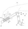
- the operation input device 2is operated by a first operation unit (arm unit) 19 operated by the hand of the operator O and the wrist or arm of the operator O.
- a second operation unit (device main body) 20 and a command transmission unit 21that transmits an operation command input by these operation units 19 and 20 to the medical manipulator 3.
- the first operation unit 19is configured to be similar to the movable unit 9 of the medical manipulator 3, and the gripping unit 25 supported by the same number of joints 22, 23, and 24 as the movable unit 9 is used by the operator O. It is held by the hand and can be moved by the hand of the operator O.
- the first operation unit 19is provided with an angle sensor (not shown) that detects the angles of the joints 22, 23, and 24 constituting the first operation unit 19.
- each first operation unit 19can input an operation command by the hand of the operator O and generate an operation command including an electrical signal.
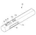
- the grip portion 25is formed in a rod shape that is gripped by the operator O, and has a slide sensor (operation portion) 16 and three push buttons 17 a, 17 b, and 17 c on the outer peripheral surface thereof. And a contact sensor (sensor) 18.
- the slide sensor 16is provided so as to be slidable in the longitudinal axis direction of the rod-shaped grip portion 25 and is used to adjust the opening / closing angle of the gripper, which is one of the main functions of the high-frequency gripper 11 as an end effector. It is like that.
- the slide sensor 16includes a slidable slider 32, and the slider 32 is maintained at a position where the index finger is released.
- buttons 17a, 17b, 17cOf the three push buttons 17a, 17b, 17c, two push buttons 17a, 17b are arranged side by side in the slide direction of the slide sensor 16. These push buttons 17a and 17b are on / off switches for performing high-frequency energization from the gripper which is another main function of the high-frequency gripper 11 which is an end effector.
- the two push buttons 17a and 17bare used by being selectively pushed, for example, in the treatment in the incision mode and the coagulation mode.
- the contact sensor 18 and the other one push button 17care arranged along the longitudinal axis of the grip portion 25 at a position different from the slide sensor 16 and the like by 90 ° in the circumferential direction of the grip portion 25.
- the contact sensor 18is disposed at a position where a finger comes into contact with the gripper 25 and can detect a gripping state of the gripper 25.
- the push button 17cis, for example, a clutch button, and can switch between connection and disconnection between the operation input device 2 and the medical manipulator 3 each time it is pressed.
- the gripping portion 25is gripped like a pen by the operator O as shown in FIGS. 4A and 4B.
- the gripper 25is gripped by the thumb and middle finger (not shown) of the operator O so that the gripper 25 is sandwiched in the horizontal direction, and the gripper 25 sandwiched between two fingers. Is designed to maintain a stable posture.
- the index fingeris not used to stably hold the grip portion 25 and can be moved relatively freely without affecting the posture of the grip portion 25.
- the grasping portion 25is made like a pen. As long as the user is gripping, it is detected that the thumb is in contact with the contact sensor 18 and is in a gripping state. Further, at this time, as shown in FIG. 4A, the slide sensor 16 can be freely slid in the longitudinal direction of the grip portion 25 with the free index finger, and is slid with the index finger as shown in FIG. 4B. Two push buttons 17a and 17b arranged side by side on the sensor 16 can be pushed.
- the thumbcan be moved relatively freely with the gripping part 25 supported by the index finger and the middle finger, and from the state where the gripping part 25 is gripped and in contact with the contact sensor 18,
- the connection between the operation input device 2 and the medical manipulator 3can be switched between connection and disconnection by moving the thumb to the position.
- the gripping unit 25is arranged as shown in FIG. 6 from a state in which a palm is placed below the gripping unit 25 and gripped like a pen, as shown in FIG.
- the gripper 25can be held and held in a state where the palm is placed on the upper surface of the gripper 25.
- the grip portion 25is gripped in the horizontal direction by the thumb and the middle finger, and the index finger is attached to the upper surface of the grip portion 25 and moved relatively freely. Can be done.
- the second operation unit 20includes an arm rest 26 fixed to the base of the first operation unit 19 and a linear motion mechanism that supports the arm rest 26 and the first operation unit 19 so as to be integrally movable. 27.
- the arm rest 26is disposed at a position where the arm near the wrist of the hand that grips the grip portion 25 is placed when the operator O grips the grip portion 25 of the first operation portion 19.
- the linear motion mechanism 27can move the slider 28 in two horizontal directions perpendicular to each other, as indicated by a solid arrow in FIG. 2 and a slider 28 that fixes the arm rest 26 and the first operation unit 19. And a linear guide 29 to be supported.
- the position of the first operation unit 19can be moved while maintaining the posture in which the first operation unit 19 is held by moving the slider 28 in the horizontal direction by the arm placed on the arm rest 26. It has become.
- the second operation unit 20can input an operation command with the wrist or arm of the operator O, and can generate the force input with the wrist or arm as the mechanical driving force of the two sliders 28. It is like that.
- the command transmission unit 21includes an electrical signal transmission unit 30 that connects the first operation unit 19 and the distal end drive unit 10, and a mechanical power transmission unit that connects the second operation unit 20 and the proximal end side operation unit 15. 31.
- the electric signal transmission unit 30transmits an operation command including the electric signal generated by the first operation unit 19 to the control unit 4, and transmits the command signal generated by the control unit 4 to each motor of the tip driving unit 10. It comes to supply.
- the control unit 4Based on the operation command generated by the first operation unit 19, the control unit 4 calculates the rotational movement amount and the rotational speed of each motor of the tip driving unit 10 and controls each motor.
- control unit 4controls the end effector 11 so as to change the opening / closing angle of the high-frequency gripper 11 in accordance with the slide position of the slider 32 of the slide sensor 16 provided in the grip unit 25 of the first operation unit 19. It is like that. Further, when the push buttons 17a, 17b, and 17c are pushed, the control unit 4 functions that are assigned to the push buttons 17a, 17b, and 17c, that is, energization in the incision mode and energization in the coagulation mode. This controls the on / off of the clutch and the engagement / disengagement of the clutch.
- control unit 4enables the operation input device 2 to control the medical manipulator 3 in a state where the grip unit 25 is gripped by the contact of the thumb with the contact sensor 18, and the thumb is separated from the contact sensor 18.
- the medical manipulator 3is controlled so as to stop.
- the operation input device 2 and the medical manipulator system 1configured as described above will be described below.
- the insertion part 6 of the medical manipulator 3is inserted into the body cavity of the patient P, and the channel R of the insertion part 6 is set. Then, the movable part 9 and the long part 8 are inserted into the body of the patient P.
- the operator Ooperates the operation input device 2 while confirming an image acquired by an endoscope (not shown) on the monitor 5 in a state where the movable portion 9 is arranged close to the affected part in the body cavity. .
- the operator Oholds the grip portion 25 of the first operation portion 19 with one hand, and the arm of the hand is placed on the arm rest 26 of the second operation portion 20. Put it on.
- the slider 28 to which the arm rest 26 is fixedmoves in the direction of the force, and the amount of movement is the amount of straight movement in the forward / backward direction.
- the front end position of the high-frequency gripper 11 positioned at the front end of the movable portion 9can be manually moved roughly in the forward / backward direction and the left / right direction.
- the operator Oholds the grip portion 25 like a pen, and sandwiches the grip portion 25 between the thumb and the middle finger in the horizontal direction. 25 can be held stably.
- the control portion 4provides angle information of each joint 22, 23, 24 from the angle sensor according to the position and posture of the grip portion 25.
- the medical manipulator 3is operated based on the above.
- the control unit 4opens and closes the high frequency gripper 11 according to the position of the slider 32.
- the slider 32can be easily slid in the longitudinal direction of the grip part 25 by the operation of the index finger. Can be made.
- the grip portion 25is staggered during the operation of the slider 32. Therefore, the high frequency gripper 11 can be opened and closed without changing the tip position of the high frequency gripper 11 of the medical manipulator 3.
- the slide sensor 16 of a type that slides the slider 32 in the longitudinal direction of the grip portion 25the force applied from the index finger to the slider 32 acts in the longitudinal direction of the grip portion 25. That is, since the force which pushes the holding part 25 in the direction which cross
- the operator Oslides the thumb and presses the push button 17c. Since the medical manipulator 3 is stopped at the moment when the thumb is separated from the contact sensor 18, there is no problem even if the grip portion 25 is slightly fluctuated by shifting the thumb or pressing the push button 17 c. Further, since the push button 17c as the clutch button is arranged so as to be shifted from the position of the thumb in the state where the grip portion 25 is gripped, it is possible to prevent erroneous operation of the clutch button and to interrupt the operation of the clutch. Can be meaningful.
- the gripper 25when the gripper 25 is moved in a state where the gripper 25 is gripped like a pen, as shown in FIGS. 5A and 5B, for example, the gripper 25 is moved up and down.
- the movement range of the grip portion 25is limited to a range in which the tip of the grip portion 25 faces downward as shown in FIGS. 5A and 5B.
- the wristcannot be raised more than the state shown in FIG. 5A.
- the tip of the gripping part 25faces upward as shown in FIG. It becomes possible to move to a certain angular position.
- the slide sensor 16 and the push button 17acan be held with the index finger that can stably hold the grip portion 25 with the thumb and the middle finger of the same hand and can move relatively freely even after being held. , 17b.
- the opening / closing operation of the gripperwhich is one of the main functions of the high-frequency gripper 11 that is an end effector, is performed in accordance with the posture of the end effector 11.
- a slide sensor 16is used that maintains the slide position of the slider 32.
- the slide sensor 16is biased by a spring in the direction in which the high-frequency gripper 11 opens.
- the slider 32may be locked at each position against movement in the closing direction by a releasable ratchet mechanism.
- the index fingercan be released from the slider 32 while maintaining the state in which the living tissue is gripped by the high-frequency gripper 11, and the energizing push button 17a can be pressed by the same index finger.
- the slide sensor 16a sensor of a type in which the slider 32 is physically slid is employed. Instead, a plurality of contact sensors 18 are arranged on the surface of the grip portion 25 along the longitudinal direction, and the index finger is used. The slide position may be determined based on an output from the contact sensor 18 that detects contact.
- the high-frequency gripper 11is used as the end effector. Instead, a gripper that does not perform high-frequency output or an electric knife that performs only high-frequency output may be used. When only the gripper is used, only the slide sensor 16 needs to be operated with the index finger.
- the slide sensor 16In the case of an electric knife, on / off of energization, which is the main function of the electric knife, may be switched by the slide sensor 16.
- the two push buttons 17a and 17bare used to switch between the incision mode and the coagulation mode, and as shown in FIG. You may arrange.
- the modemay be switched by a single switch.
- a treatment instrument other than a gripper or an electric knifemay be used as the end effector 11.
- the operator O's handis placed on the upper and lower surfaces of the grip portion 25 with respect to the grip portion 25.
- the gripping part 25is gripped like a pen, or as shown in FIG. Can be determined.
- the software limiter that restricts the operation of the medical manipulator 3may be switched according to the detected holding method. Further, the functions associated with the slide sensor 16 and the push buttons 17a and 17b may be switched depending on how the grip portion 25 is held. Further, the position of the slide sensor 16 may be designed to be similar in structure to the position of the end effector 11, and the calculation reference coordinates may be switched according to how the grip portion 25 is held.
- the joint 24 that rotates the entire first operation unit 19since the joint 24 that rotates the entire first operation unit 19 is provided, when the joint 24 is rotated by the operation of the grip 25, the posture is changed so that the grip 25 is twisted around its longitudinal axis. Be made. When the grip portion 25 is rotated about the longitudinal axis, the position of each finger gripping the grip portion 25 is also rotated, so that it may be difficult to grip.
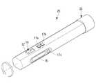
- a rotation support portion 35that supports the grip portion 25 itself so as to be rotatable about its longitudinal axis may be provided.
- the rotation of the grip portion 25 by the rotation support portion 35does not affect the operation of the medical manipulator 3.
- the grip part 25can be gripped and operated so that the finger for operating the slide sensor 16 and the like is arranged without difficulty.
- the operation of the medical manipulator 3is stopped at the moment when the thumb is separated from the contact sensor 18, but instead, a predetermined time elapses after the thumb is separated from the contact sensor 18.
- the medical manipulator 3may be stopped later.
- a time required for changing the holding part 25may be set.
- a fall detection sensorsuch as an acceleration sensor is provided, and when it is detected that the grip portion 25 is dropped, the medical manipulator 3 is stopped even within a predetermined time. Also good.
- the contact sensor 18is illustrated as being disposed at the position of the thumb, it may be replaced with a sensor disposed on the middle finger side. Further, the contact sensor 18 may be provided in a ring shape over the circumferential direction of the grip portion 25. Thus, any finger can be brought into contact with the contact sensor 18 even when holding the grip portion 25.
- a type detection unit(not shown) that detects the type of the medical manipulator 3 may be provided. Then, the control unit 4 changes the correspondence relationship between the slide sensor 16 and the main function of the end effector 11 according to the type of the medical manipulator 3 detected by the type detection unit, so that the medical manipulator 3 is replaced. Also, the medical manipulator 3 can be operated by the same operation input device 2.
Landscapes
- Health & Medical Sciences (AREA)
- Engineering & Computer Science (AREA)
- Life Sciences & Earth Sciences (AREA)
- Surgery (AREA)
- Public Health (AREA)
- Animal Behavior & Ethology (AREA)
- Biomedical Technology (AREA)
- Veterinary Medicine (AREA)
- Nuclear Medicine, Radiotherapy & Molecular Imaging (AREA)
- General Health & Medical Sciences (AREA)
- Molecular Biology (AREA)
- Medical Informatics (AREA)
- Heart & Thoracic Surgery (AREA)
- Robotics (AREA)
- Oral & Maxillofacial Surgery (AREA)
- Physics & Mathematics (AREA)
- Plasma & Fusion (AREA)
- Otolaryngology (AREA)
- Pathology (AREA)
- Radiology & Medical Imaging (AREA)
- Mechanical Engineering (AREA)
- Ophthalmology & Optometry (AREA)
- Manipulator (AREA)
- Surgical Instruments (AREA)
Abstract
Description
Translated fromJapanese本発明は、操作入力装置および医療用マニピュレータシステムに関する。The present invention relates to an operation input device and a medical manipulator system.
従来、マスタ・スレーブ方式の医療用マニピュレータシステムにおいて、操作者により操作される操作入力装置として、操作部に設けられた2個一対の把持要素を操作者の2指で開閉する方式のものが知られている(例えば、特許文献1参照。)。この操作入力装置では、把持要素の開閉によってスレーブ側の処置具のエンドエフェクタであるグリッパを開閉操作することとしている。2. Description of the Related Art Conventionally, in a master / slave type medical manipulator system, an operation input device operated by an operator is known which opens and closes a pair of gripping elements provided in an operation unit with two fingers of the operator. (For example, refer to Patent Document 1). In this operation input device, a gripper which is an end effector of a slave-side treatment instrument is opened and closed by opening and closing a gripping element.
また、ペン型の操作部を備え、操作部に設けられたレバーによってグリッパを開閉操作し、操作部の側面のスイッチによってマスタ側とスレーブ側との連動を入切する操作入力装置が知られている(例えば、特許文献2参照。)。
さらに、スレーブ側の処置具と相似構造を有する操作部を操作者の手に取り付けるとともに先端部をペンのように持つ方式の操作入力装置が知られている(例えば、特許文献3参照。)。この操作入力装置では、先端部に設けた感圧センサにより検出される力の大きさによってグリッパの開閉量を操作するようになっている。Also known is an operation input device that has a pen-type operation unit, opens and closes the gripper with a lever provided on the operation unit, and switches on and off the interlocking between the master side and the slave side with a switch on the side of the operation unit. (For example, refer to Patent Document 2).
Further, there is known an operation input device of a type in which an operation unit having a structure similar to that of a slave-side treatment tool is attached to an operator's hand and a tip portion is like a pen (for example, see Patent Document 3). In this operation input device, the opening / closing amount of the gripper is operated by the magnitude of the force detected by the pressure sensor provided at the tip.
しかしながら、特許文献1の操作入力装置は、2指によって操作部に設けられた把持要素を操作することによりグリッパの開閉を行うので、他の3指によっては操作部を安定して保持することができないうえに、2指から把持要素に加えた力の反力によって操作部自体の位置が変動してしまうという不都合がある。
また、特許文献2の操作入力装置は、ペン型の操作部をペンのように持つ方式であり、その持ち方は限定されているため、操作部を持つ手の手首の可動範囲の狭さによって、操作量が制限されてしまうという不都合がある。However, since the operation input device of
Further, the operation input device of
本発明は上述した事情に鑑みてなされたものであって、エンドエフェクタの主機能の操作をエンドエフェクタの姿勢を安定させたまま行うことができるとともに、手首の可動範囲による操作量の制限を緩和することができる操作入力装置および医療用マニピュレータシステムを提供する。The present invention has been made in view of the above-described circumstances, and can perform the operation of the main function of the end effector while keeping the posture of the end effector stable, and relaxes the limitation of the operation amount due to the movable range of the wrist. Provided are an operation input device and a medical manipulator system that can be used.
上記目的を達成するために、本発明は以下の手段を提供する。
本発明の第一の態様は、患部の観察または処置を行うエンドエフェクタを有するマニピュレータへの操作指令を入力する操作入力装置であって、操作者の同一の手によって持ち替えて把持可能な把持部と、該把持部に設けられ、持ち替え前後において同一の単一指により操作され前記エンドエフェクタの主機能を操作する操作部とを備える操作入力装置である。In order to achieve the above object, the present invention provides the following means.
A first aspect of the present invention is an operation input device for inputting an operation command to a manipulator having an end effector for observing or treating an affected area, and a gripper that can be held and held by the same hand of an operator The operation input device includes an operation unit that is provided in the grip unit and that is operated by the same single finger before and after the change of position and operates the main function of the end effector.
本態様に係る操作入力装置によれば、操作者が把持部を把持して、把持部に設けられた操作部を操作することにより、マニピュレータに設けられたエンドエフェクタの主機能を操作するための操作指令が入力され、患者の観察または処置が行われる。操作部は、操作者の単一指によって操作されるので、当該指を除く他の指で把持部を確りと把持して安定させた状態で操作することができ、エンドエフェクタの主機能の操作をエンドエフェクタの姿勢を安定させたまま行うことができる。According to the operation input device according to this aspect, the operator grips the grip portion and operates the operation unit provided in the grip portion, thereby operating the main function of the end effector provided in the manipulator. An operation command is input, and the patient is observed or treated. Since the operation unit is operated by a single finger of the operator, it can be operated in a state in which the gripping unit is firmly grasped and stabilized by other fingers except the finger, and the operation of the main function of the end effector can be performed. Can be performed while the posture of the end effector is stabilized.
また、操作者は、一方の手で把持した操作部の把持部を移動させることによりエンドエフェクタを移動させ、その手の単一の指により操作部を操作してエンドエフェクタの主機能を操作している状態から、把持部を把持している同一の手による把持部の持ち方を変更することができる。これにより、把持部の持ち方に応じて手首の可動範囲が制限される場合においても、持ち方を変えることで可動範囲を広げることができ、操作量が制限されてしまう不都合を緩和することができる。そして、把持部を持ち替えたときに、持ち替え前後において操作部をする指が変わらないので、操作者が混乱することなく操作し続けることができる。In addition, the operator moves the end effector by moving the gripping part of the operation part gripped with one hand, and operates the operation part with a single finger of the hand to operate the main function of the end effector. The holding method of the grip part by the same hand holding the grip part can be changed. Thereby, even when the movable range of the wrist is limited depending on how to hold the grip portion, the movable range can be expanded by changing the holding method, and the inconvenience that the operation amount is limited can be reduced. it can. When the holding part is changed, the finger that operates the operation part does not change before and after the change of the holding part, so that the operator can continue to operate without confusion.
上記態様に係る操作入力装置において、前記把持部に、該把持部を把持している操作者の手の把持状態を検出するセンサを備えていてもよい。
このようにすることで、操作者の手が把持部を把持していることがセンサにより検出された場合に操作部を有効にしたり、操作入力装置によるマニピュレータの操作を可能にしたりすることができる。In the operation input device according to the above aspect, the grip portion may include a sensor that detects a grip state of an operator's hand gripping the grip portion.
By doing so, it is possible to enable the operation unit when the sensor detects that the operator's hand is holding the grip unit, or to enable operation of the manipulator by the operation input device. .
上記態様に係る操作入力装置において、前記センサが接触センサであってもよい。
このようにすることで、操作者が把持部を軽く把持しているだけでも、把持する手が接触センサに接触していれば、把持状態を検出することができ、操作者にかかる労力を軽減することができる。In the operation input device according to the above aspect, the sensor may be a contact sensor.
In this way, even if the operator is lightly gripping the gripping part, the gripping state can be detected as long as the gripping hand is in contact with the contact sensor, reducing the labor on the operator. can do.
上記態様に係る操作入力装置において、前記センサが、前記操作者による前記把持部の持ち替え操作を検出する構成であってもよい。
この構成によれば、センサが操作者による把持部の持ち替え操作を検出したときに、操作入力装置とマニピュレータとを切断することなく接続し続けることにより、途切れのない円滑な処置を行うことができる。逆に、センサが操作者による把持部の持ち替え操作を検出したときに、操作入力装置とマニピュレータとを切断することにより、持ち替え時の把持部の意図しない動きによって、マニピュレータが意図しない動作をすることを防止することができる。In the operation input device according to the above aspect, the sensor may be configured to detect a holding operation of the gripper by the operator.
According to this configuration, when the sensor detects an operation of changing the gripping portion by the operator, the operation input device and the manipulator are continuously connected without being disconnected, so that a smooth treatment without interruption can be performed. . On the other hand, when the sensor detects the holding operation of the gripping part by the operator, the operation input device and the manipulator are disconnected to cause the manipulator to perform an unintended operation due to the unintended movement of the gripping part at the time of switching. Can be prevented.
上記態様に係る操作入力装置において、前記操作部が、前記把持部に対して前記単一指をスライドすることにより前記エンドエフェクタの主機能の操作量を調節するスライドセンサであってもよい。
このようにすることで、単一指をスライドさせることによるスライドセンサの操作によって、エンドエフェクタの主機能の操作量を、把持部の姿勢を変動させるような力を加えることなく調節することができる。すなわち、操作部の操作によっても把持部の姿勢が変動しないので、姿勢をさらに安定させた状態でエンドエフェクタを操作することができる。In the operation input device according to the above aspect, the operation unit may be a slide sensor that adjusts an operation amount of a main function of the end effector by sliding the single finger with respect to the grip unit.
In this way, the operation amount of the main function of the end effector can be adjusted without applying a force that fluctuates the posture of the gripper by operating the slide sensor by sliding a single finger. . In other words, since the posture of the grip portion does not change even when the operation portion is operated, the end effector can be operated in a state where the posture is further stabilized.
上記態様に係る操作入力装置において、装置本体と該装置本体に対して前記把持部を移動可能に接続するアーム部とを備え、前記アーム部に、前記把持部をその長手軸回りに回転可能に支持する回転支持部を備えていてもよい。
このようにすることで、操作者が把持部を手で把持して移動させる場合に、装置本体に対する把持部の位置および姿勢が変化するが、その変化に追従するようにアーム部が変形し、その変形量に基づいてマニピュレータが動作させられる。把持部を把持する手の単一指により操作部を操作する場合に、把持部の姿勢の変動に追従させてアーム部を変形させる場合にアーム部の軸構成によっては把持部がその長手軸回りに回転するので回転支持部の回転によって把持部の回転をキャンセルすることにより、把持部を無理なく把持することができる。The operation input device according to the above aspect includes an apparatus main body and an arm part that movably connects the grip part to the apparatus main body, and the arm part can rotate the grip part about its longitudinal axis. You may provide the rotation support part to support.
By doing so, when the operator grips and moves the gripping part by hand, the position and posture of the gripping part with respect to the apparatus main body change, but the arm part deforms to follow the change, The manipulator is operated based on the deformation amount. When operating the operating unit with a single finger of the hand that holds the gripping part, if the arm part is deformed following the change in the posture of the gripping part, the gripping part may turn around its longitudinal axis depending on the axis configuration of the arm part. Therefore, the gripping part can be gripped without difficulty by canceling the rotation of the gripping part by the rotation of the rotation support part.
本発明の第二の態様は、患部の観察または処置を行うエンドエフェクタを有するマニピュレータと、上記いずれかの操作入力装置と、該操作入力装置により入力された操作指令に基づいて前記マニピュレータを制御する制御部とを備える医療用マニピュレータシステムである。According to a second aspect of the present invention, a manipulator having an end effector that observes or treats an affected area, any one of the operation input devices, and the manipulator is controlled based on an operation command input by the operation input device. A medical manipulator system including a control unit.
本態様に係る医療用マニピュレータシステムによれば、操作者が操作入力装置を介して操作指令を入力することにより、制御部が操作指令に基づいてマニピュレータを制御し、マニピュレータによって患部の関節または処置が行われる。この場合に、操作入力装置において、操作者が把持する把持部が持ち替え可能であり、かつ、持ち替え前後において、同一の指でエンドエフェクタの主機能を操作することができる。したがって、エンドエフェクタの主機能の操作をエンドエフェクタの姿勢を安定させたまま行うことができるとともに、手首の可動範囲による操作量の制限を緩和することができる。According to the medical manipulator system according to this aspect, when the operator inputs an operation command via the operation input device, the control unit controls the manipulator based on the operation command, and the joint or treatment of the affected area is performed by the manipulator. Done. In this case, in the operation input device, the gripping part gripped by the operator can be changed, and the main function of the end effector can be operated with the same finger before and after the change. Therefore, the operation of the main function of the end effector can be performed while the posture of the end effector is stabilized, and the restriction on the operation amount due to the movable range of the wrist can be relaxed.
上記態様に係る医療用マニピュレータシステムにおいて、前記操作入力装置が、前記操作者の手の前記把持部に対する位置を検出する位置検出部を備え、前記制御部が、前記位置検出部により検出された前記操作者の手の位置に応じて前記マニピュレータへの指令信号を切り替える構成であってもよい。
この構成によれば、位置検出部が把持部に対する操作者の手の位置を検出すると、検出された手の位置に応じて制御部がマニピュレータへの指令信号を切り替えることにより、持ち方の切替に関わらずマニピュレータをスムーズに操作することができる。In the medical manipulator system according to the aspect described above, the operation input device includes a position detection unit that detects a position of the operator's hand with respect to the grip unit, and the control unit is detected by the position detection unit. The configuration may be such that the command signal to the manipulator is switched according to the position of the operator's hand.
According to this configuration, when the position detection unit detects the position of the operator's hand with respect to the grip unit, the control unit switches the command signal to the manipulator according to the detected hand position, thereby switching the holding method. Regardless, the manipulator can be operated smoothly.
上記態様に係る医療用マニピュレータシステムにおいて、前記操作入力装置が、前記操作部を複数備え、前記制御部が、前記位置検出部により検出された操作者の手の位置に応じて、前記操作部と前記エンドエフェクタの主機能との対応関係を変更する構成であってもよい。
この構成によれば、把持部の持ち方に応じて、各持ち方に適した位置に配置される操作部によって操作し易くすることができる。In the medical manipulator system according to the above aspect, the operation input device includes a plurality of the operation units, and the control unit includes the operation unit and the operation unit according to the position of the operator's hand detected by the position detection unit. The configuration may be such that the correspondence with the main function of the end effector is changed.
According to this configuration, it is possible to facilitate the operation by the operation unit arranged at a position suitable for each holding method according to how the holding unit is held.
上記態様に係る医療用マニピュレータシステムにおいて、前記マニピュレータの種類を検出する種類検出部を備え、前記制御部が、前記種類検出部により検出された前記マニピュレータの種類に応じて、前記操作部と前記エンドエフェクタの主機能との対応関係を変更する構成であってもよい。
この構成によれば、種類検出部により検出されたマニピュレータの種類に応じて制御部が各操作部にエンドエフェクタの主機能との対応関係を変更するので、マニピュレータを交換しても同じ操作入力装置によってマニピュレータを操作することができる。The medical manipulator system according to the above aspect includes a type detection unit that detects the type of the manipulator, and the control unit and the end according to the type of the manipulator detected by the type detection unit. The structure which changes the correspondence with the main function of an effector may be sufficient.
According to this configuration, since the control unit changes the correspondence relationship with the main function of the end effector to each operation unit according to the type of the manipulator detected by the type detection unit, the same operation input device even if the manipulator is replaced The manipulator can be operated by.
また、本発明の第三の態様は、患部の観察または処置を行うエンドエフェクタを有するマニピュレータと、上記いずれかの操作入力装置と、該操作入力装置により入力された操作指令に基づいて前記マニピュレータを制御する制御部とを備え、該制御部は、前記センサにより、前記把持部が前記操作者の手により把持されていないことが検出された場合に、前記マニピュレータの動作を停止するよう制御する医療用マニピュレータシステムである。The third aspect of the present invention provides a manipulator having an end effector for observing or treating an affected area, one of the operation input devices, and the manipulator based on an operation command input by the operation input device. A control unit that controls the medical unit to stop the operation of the manipulator when the sensor detects that the grip unit is not gripped by the operator's hand. Manipulator system.
本態様に係る医療用マニピュレータシステムによれば、操作者により把持部が把持されていないことをセンサが検出したときに、マニピュレータの動作を停止させることにより、持ち替え時に把持部を手放してしまうことによる把持部の意図しない動きによって、マニピュレータが意図しない動作をすることを防止することができる。According to the medical manipulator system according to this aspect, when the sensor detects that the grip portion is not gripped by the operator, the operation of the manipulator is stopped, so that the grip portion is released at the time of holding. It is possible to prevent the manipulator from performing an unintended operation due to an unintended movement of the grip portion.
本発明によれば、エンドエフェクタの主機能の操作をエンドエフェクタの姿勢を安定させたまま行うことができるとともに、手首の可動範囲による操作量の制限を緩和することができるという効果を奏する。According to the present invention, it is possible to operate the main function of the end effector while keeping the posture of the end effector stable, and it is possible to relax the limitation of the operation amount due to the movable range of the wrist.
本発明の一実施形態に係る操作入力装置2および医療用マニピュレータシステム1について、図面を参照して以下に説明する。
本実施形態に係る医療用マニピュレータシステム1は、図1に示されるように、操作者Oにより操作される操作入力装置2と、患者Pの体腔内に挿入される医療用マニピュレータ(マニピュレータ)3と、操作入力装置2の操作に基づいて医療用マニピュレータ3を制御する制御部4と、モニタ5とを備えている。An
As shown in FIG. 1, a
医療用マニピュレータ3は、例えば、図2に示されるように、患者Pの体腔内に挿入される挿入部6と、該挿入部6の長手方向に貫通形成されたチャネルRを介して患者Pの体内に挿入される先端側動作部7とを備えている。各先端側動作部7は、チャネルR内に長手方向に移動可能に配置される長尺部8と、該長尺部8の先端に備えられた可動部9と、可動部9の先端に設けられた高周波グリッパ(エンドエフェクタ)11と、長尺部8の基端側に配置され、図示しないワイヤ等の動力伝達部材によって可動部9を駆動する先端駆動部10とを備えている。先端駆動部10は、制御部4からの動作指令に応じてワイヤに張力を付与するモータ等の電気的な駆動源(図示略)を備えている。For example, as shown in FIG. 2, the
各可動部9は、図2に白抜きの矢印で示すように、先端に配置される高周波グリッパ11を2つの平行な軸線回りに揺動させる2つの関節12,13と、長尺部8の長手軸回りに回転させる1つの関節14とを有している。各可動部9は、これら3つの関節12,13,14の動作によって各高周波グリッパ11の先端位置を3次元的に位置決めすることができるようになっている。Each
また、医療用マニピュレータ3は、各先端側動作部7の基端側に接続され、各先端側動作部7を挿入部6の長手方向に進退させるとともに、挿入部6の基端近傍において、長尺部8を長手方向に直交する方向に湾曲させる2つの基端側動作部15を備えている。Further, the
本実施形態に係る操作入力装置2は、図2に示されるように、操作者Oの手によって操作される第1の操作部(アーム部)19と、操作者Oの手首または腕によって操作される第2の操作部(装置本体)20と、これらの操作部19,20により入力された操作指令を医療用マニピュレータ3に伝達する指令伝達部21とを備えている。As shown in FIG. 2, the
第1の操作部19は、医療用マニピュレータ3の可動部9と相似形に構成されており、可動部9と同じ数の関節22,23,24によって支持された把持部25が操作者Oの手によって把持されて、操作者Oの手により移動させられるようになっている。第1の操作部19には、該第1の操作部19を構成している各関節22,23,24の角度を検出する図示しない角度センサが備えられている。The
角度センサは、各関節22,23,24の角度に応じた電気信号を発生するようになっている。これにより、各第1の操作部19は、操作者Oの手により操作指令を入力し、電気信号からなる動作指令を発生することができるようになっている。The angle sensor generates electrical signals according to the angles of the
把持部25は、図2および図3に示されるように、操作者Oによって把持される棒状に形成され、その外周面に、スライドセンサ(操作部)16、3つの押しボタン17a,17b,17cおよび接触センサ(センサ)18を備えている。
スライドセンサ16は、棒状の把持部25の長手軸方向にスライド可能に設けられており、エンドエフェクタである高周波グリッパ11の主機能の1つであるグリッパの開閉角度を調節するために使用されるようになっている。スライドセンサ16は、スライド可能なスライダ32を備えるとともに、人差し指を離した位置にスライダ32が維持されるようになっている。As shown in FIGS. 2 and 3, the
The
3つの押しボタン17a,17b,17cのうちの2つの押しボタン17a,17bは、スライドセンサ16のスライド方向に並んで配列されている。これらの押しボタン17a,17bは、エンドエフェクタである高周波グリッパ11の他の主機能であるグリッパからの高周波通電を行うためのオンオフスイッチである。2つの押しボタン17a,17bは、例えば、切開モード、凝固モードでの処置の際に選択的に押されて使用されるようになっている。Of the three
接触センサ18および他の1つの押しボタン17cは、スライドセンサ16等とは把持部25の周方向に90°異なる位置に、把持部25の長手軸に沿って配列されている。接触センサ18は、把持部25を把持する場合に指が接触する位置に配置されており、把持部25の把持状態を検出することができるようになっている。押しボタン17cは、例えば、クラッチボタンであり、押す都度に操作入力装置2と医療用マニピュレータ3との連携の接続と切断とを切り替えることができるようになっている。The
本実施形態においては、把持部25は、図4A及び図4Bに示されるように、操作者Oによりペンのように把持されるようになっている。この場合、図4Aに示されるように、操作者Oの手の親指と中指(図示略)とによって、把持部25が水平方向に挟まれるように把持され、2指に挟まれた把持部25は安定した姿勢に維持されるようになっている。
このとき、人差し指は把持部25を安定して把持するためには使用されず、把持部25の姿勢に影響を与えることなく比較的自由に動かすことができるようになっている。In the present embodiment, the gripping
At this time, the index finger is not used to stably hold the
したがって、このように把持されるときに親指が配置される位置に接触センサ18を配置し、人差し指が配置される位置にスライドセンサ16を配置しておくことにより、把持部25をペンのように把持している限り、親指が接触センサ18に接触して把持状態であることが検出されるようになっている。また、このとき、図4Aに示されるように、フリーとなっている人差し指によってスライドセンサ16を把持部25の長手方向に自在にスライドさせることができ、図4Bに示されるように、人差し指によってスライドセンサ16に並んで配列されている2つの押しボタン17a,17bを押すことができるようになっている。Therefore, by arranging the
さらに、把持部25を人差し指と中指とで支持した状態で、親指を比較的自由に移動させることができ、把持部25を把持して接触センサ18に接触している状態から、押しボタン17cの位置まで親指を移動させて操作入力装置2と医療用マニピュレータ3との連携の接続と切断とを切り替えることができるようになっている。Further, the thumb can be moved relatively freely with the
また、本実施形態においては、把持部25は、図4Aに示されるように、把持部25の下方に掌を配置してペンのように把持される状態から、図6に示されるように、把持部25の上面に掌を被せるよう配置する状態に持ち替えて把持することができるようになっている。
この場合において、図6のような持ち方を選択した場合においても、把持部25は親指と中指とによって水平方向に把持され、人差し指は把持部25の上面に添えられて比較的自由に動かすことができるようになっている。Further, in the present embodiment, as shown in FIG. 6, the gripping
In this case, even when the holding method as shown in FIG. 6 is selected, the
第2の操作部20は、第1の操作部19の基部に固定された腕置き台26と、該腕置き台26および第1の操作部19を一体的に移動可能に支持する直動機構27とを備えている。腕置き台26は、操作者Oが第1の操作部19の把持部25を把持したときに、丁度把持部25を把持する手の手首近傍の腕が載せられる位置に配置されている。The
直動機構27は、腕置き台26および第1の操作部19を固定するスライダ28と、図2に黒塗りの矢印で示すように、該スライダ28を相互に直交する水平2方向に移動可能に支持する直線ガイド29とを備えている。腕置き台26に乗せた腕によってスライダ28を水平方向に移動させることにより第1の操作部19を把持した姿勢を維持したままで、第1の操作部19の位置を移動させることができるようになっている。これにより、第2の操作部20は、操作者Oの手首または腕により操作指令を入力し、手首または腕により入力した力を、2つのスライダ28の機械的な駆動力として発生することができるようになっている。The
指令伝達部21は、第1の操作部19と先端駆動部10とを接続する電気信号伝達部30と、第2の操作部20と基端側動作部15とを接続する機械的動力伝達部31とを備えている。
電気信号伝達部30は、第1の操作部19により発生された電気信号からなる動作指令を制御部4に伝達し、制御部4によって生成された指令信号を、先端駆動部10の各モータに供給するようになっている。制御部4は、第1の操作部19により発生した動作指令に基づいて、先端駆動部10の各モータの回転移動量および回転速度を算出し各モータを制御するようになっている。The
The electric
また、制御部4は、第1の操作部19の把持部25に設けられたスライドセンサ16のスライダ32のスライド位置に応じて高周波グリッパ11の開閉角度を変更するようにエンドエフェクタ11を制御するようになっている。また、制御部4は、押しボタン17a,17b,17cが押されたときには、各押しボタン17a,17b,17cに割り当てられた機能、すなわち、切開モードでの通電の入切、凝固モードでの通電の入切、クラッチの断続を制御するようになっている。Further, the
さらに、制御部4は、接触センサ18への親指の接触により、把持部25が把持されている状態において、操作入力装置2による医療用マニピュレータ3の制御を可能とし、接触センサ18から親指が離れたときには、医療用マニピュレータ3を停止するように制御するようになっている。Furthermore, the
このように構成された本実施形態に係る操作入力装置2および医療用マニピュレータシステム1の作用について以下に説明する。
本実施形態に係る医療用マニピュレータシステム1を用いて患者Pの体内の患部を処置するには、患者Pの体腔内に医療用マニピュレータ3の挿入部6を挿入し、挿入部6のチャネルRを介して患者Pの体内に可動部9および長尺部8を挿入する。The operation of the
In order to treat the affected part in the body of the patient P using the
そして、可動部9が体腔内の患部に近接して配置された状態で、操作者Oは、図示しない内視鏡により取得された画像をモニタ5で確認しながら、操作入力装置2を操作する。操作入力装置2を操作するには、操作者Oは、第1の操作部19の把持部25を一方の手で把持し、その手の腕を第2の操作部20の腕置き台26に乗せる。Then, the operator O operates the
そして、操作者Oが、腕から腕置き台26に力を加えると、腕置き台26が固定されたスライダ28がその力の方向に移動し、その移動量が、前後進方向の直進移動量と、左右方向の直進移動量とに分解されて、それぞれ、可動部9の先端に位置する高周波グリッパ11の先端位置を手動によって前後進方向および左右方向に大まかに移動させることができる。When the operator O applies a force from the arm to the
一方、操作者Oが手で把持している第1の操作部19の把持部25を移動させると、その移動量が各関節22,23,24に設けられた角度センサによって検出され、電気信号として制御部4に伝達される。制御部4においては角度センサによって検出された各関節22,23,24の角度に一致するように可動部9の各関節12,13,14を動作させる電気的な動作指令が算出されて、各関節12,13,14に接続されたモータに供給される。これにより、可動部9の先端に設けられている高周波グリッパ11の先端位置が手の動作によって指示された通りに電動で精密に移動させられる。On the other hand, when the operator O moves the
この場合において、操作者Oは、図4A及び図4Bに示されるように、把持部25をペンのように把持しており、親指と中指とで把持部25を水平方向に挟むことで把持部25を安定的に保持することができる。このとき、親指は把持部25に設けられた接触センサ18に接触しているので、制御部4は把持部25の位置および姿勢に応じた角度センサからの各関節22,23,24の角度情報に基づいて医療用マニピュレータ3を動作させる。In this case, as shown in FIGS. 4A and 4B, the operator O holds the
そして、操作者Oが、高周波グリッパ11により生体組織を把持するようにスライドセンサ16のスライダ32をスライドさせたときには、制御部4がスライダ32の位置に応じて高周波グリッパ11を開閉させる。この場合に、把持部25を把持している操作者Oの手の人差し指がスライダ32に接触する位置に配置されているので、人差し指の動作によりスライダ32を把持部25の長手方向に容易にスライドさせることができる。When the operator O slides the
すなわち、親指と中指とで挟むことにより安定して保持されている把持部25に対して、比較的自由に動かせる人差し指によってスライダ32が操作されるので、スライダ32の操作中に把持部25がふらつくことがなく、医療用マニピュレータ3の高周波グリッパ11の先端位置を変動させずに高周波グリッパ11を開閉することができる。
特に、スライダ32を把持部25の長手方向にスライドさせる形式のスライドセンサ16を採用することにより、人差し指からスライダ32に加える力は把持部25の長手方向に作用する。すなわち、把持部25を長手軸に交差する方向に押す力が作用しないので、把持部25のふらつきを防止する効果が高められる。That is, since the
In particular, by adopting the
そして、高周波グリッパ11によって生体組織が把持された状態で人差し指により押しボタン17aを押すことで、高周波グリッパ11から生体組織に対して高周波通電が行われ、生体組織の切開や凝固のような処置を行うことができる。処置の段階では、高周波グリッパ11が生体組織を把持しているので、押しボタン17a,17bの押下によって把持部25に多少のふらつきが生じても問題はない。Then, by pressing the
また、操作入力装置2と医療用マニピュレータ3との連携を切断したいときには、操作者Oは親指をスライドさせて押しボタン17cを押す。親指が接触センサ18から離れた瞬間に医療用マニピュレータ3が停止されるので、親指のシフトや押しボタン17cの押下により把持部25に多少のふらつきが生じても問題とはならない。また、クラッチボタンとしての押しボタン17cは把持部25を把持している状態の親指の位置からずらして配置しているので、クラッチボタンの誤操作を防止することができるとともに、クラッチでの操作中断を意味づけることができる。Further, when it is desired to disconnect the cooperation between the
ここで、把持部25をペンのように把持している状態で、把持部25を移動させる場合には、図5A及び図5Bに示されるように、例えば、把持部25を上下方向に移動させる場合に、手首の動作範囲の制限によって、把持部25の動作範囲は図5A及び図5Bに示されるように把持部25の先端が下向きとなっている範囲に制限される。特に、図5Aに示される状態以上に手首を上向きにすることはできない。Here, when the
本実施形態においては、このような場合に、把持部25を同じ手で、図6に示されるような持ち方に持ち替えることにより、図7に示されるように、把持部25の先端が上向きとなる角度位置まで移動させることができるようになる。
この場合に、持ち替えた後においても、同じ手の親指と中指とによって把持部25を水平方向に挟むようにして安定して把持し、かつ、比較的自由に移動できる人差し指によってスライドセンサ16および押しボタン17a,17bを押すことができる。In this embodiment, in such a case, by holding the
In this case, the
このように、本実施形態に係る操作入力装置2および医療用マニピュレータシステム1によれば、エンドエフェクタである高周波グリッパ11の主機能の1つであるグリッパの開閉の操作をエンドエフェクタ11の姿勢を安定させたまま行うことができるとともに、手首の可動範囲による操作量の制限を緩和することができるという利点がある。Thus, according to the
なお、本実施形態においては、スライドセンサ16として、スライダ32のスライド位置が維持される方式のものを採用したが、これに代えて、スライドセンサ16をバネによって高周波グリッパ11が開く方向に付勢しておき、解除可能なラチェット機構によって閉じる方向への移動に対しては各位置にスライダ32をロックできるようにしてもよい。これにより、生体組織を高周波グリッパ11によって把持した状態を維持しながらスライダ32から人差し指を離すことができ、同じ人差し指によって通電用の押しボタン17aを押下することができる。In the present embodiment, a
また、スライドセンサ16として、スライダ32を物理的にスライドさせる方式のセンサを採用したが、これに代えて、複数の接触センサ18を把持部25の表面に長手方向に沿って配列し、人差し指の接触を検出する接触センサ18からの出力によりスライド位置を決定することにしてもよい。Further, as the
また、本実施形態においては、エンドエフェクタとして、高周波グリッパ11を採用したが、これに代えて、高周波出力を行わないグリッパや高周波出力のみを行う電気メスを採用してもよい。グリッパのみの場合、人差し指で操作するのはスライドセンサ16のみでよい。In this embodiment, the high-
また、電気メスの場合、電気メスの主機能である通電のオンオフをスライドセンサ16によって切り替えてもよい。この場合に、2つの押しボタン17a,17bを、切開モードと凝固モードの切替に使用し、図8に示されるように、選択されているモードを色によって表示する表示灯33を把持部25に配置してもよい。2つの押しボタン17a,17bに代えて、単一のスイッチによってモードを切り替えることにしてもよい。グリッパや電気メス以外の処置具をエンドエフェクタ11としてもよい。In the case of an electric knife, on / off of energization, which is the main function of the electric knife, may be switched by the
また、接触センサ18に代えて、または、接触センサ18に加えて、図9A及び図9Bに示されるように、把持部25の上下面に配置され把持部25に対して操作者Oの手が上下のどちらに配置されているのかを検出する近接センサ(位置検出部)34を採用してもよい。
このようにすることで、図9Aに示されるように、把持部25をペンのように把持しているのか、図9Bに示されるように、把持部25の上に手を被せるように把持しているのかを判定することができる。Further, instead of the
In this way, as shown in FIG. 9A, the
上述したように、把持部25の持ち方によって動作範囲が異なるので、検出された持ち方に応じて医療用マニピュレータ3の動作制限を行うソフトウェアリミッタを切り替えることにしてもよい。また、スライドセンサ16や押しボタン17a,17bに対応づけている機能を把持部25の持ち方によって切り替えることにしてもよい。また、スライドセンサ16の位置がエンドエフェクタ11の位置と相似構造的に同一となるように設計し、把持部25の持ち方に応じて、計算基準座標を切り替えることにしてもよい。As described above, since the operation range varies depending on how the
また、第1の操作部19全体を回転させる関節24を有しているので、把持部25の操作によって関節24が回転させられると、把持部25がその長手軸回りに捻られるように姿勢変更させられる。把持部25が長手軸回りに回転されると把持部25を把持している各指の位置も回転していくため、把持しにくい状態になることが考えられる。Further, since the joint 24 that rotates the entire
そこで、図10に示されるように、把持部25自体をその長手軸回りに回転自在に支持する回転支持部35を設けてもよい。回転支持部35による把持部25の回転は医療用マニピュレータ3の動作に影響しないようになっている。これにより、スライドセンサ16等を操作する指が無理なく配置されるように把持部25を把持して操作することができる。Therefore, as shown in FIG. 10, a
また、上記実施形態においては、接触センサ18から親指が離れた瞬間に、医療用マニピュレータ3の動作を停止させることとしたが、これに代えて、接触センサ18から親指が離れてから所定時間経過後に医療用マニピュレータ3を停止させることにしてもよい。この場合に所定時間としては、把持部25の持ち替えに必要な時間を設定しておけばよい。In the above embodiment, the operation of the
これにより、把持部25の持ち替え時に途切れなく医療用マニピュレータ3を操作し続けることができる。また、接触センサ18に加えて加速度センサのような落下検知センサを設け、把持部25が落下したことが検知された場合には所定時間内であっても医療用マニピュレータ3を停止させることにしてもよい。This makes it possible to continue operating the
また、接触センサ18として、親指の位置に配置されるものを例示したが、これに代えて、中指側に配置されるものを採用してもよい。
また、把持部25の周方向にわたってリング状に接触センサ18が設けられていてもよい。これにより、把持部25を持ち替える際にもいずれかの指を接触センサ18に接触状態にすることができる。In addition, although the
Further, the
また、本実施形態においては、医療用マニピュレータ3の種類を検出する種類検出部(図示略)を備えていてもよい。
そして、種類検出部により検出された医療用マニピュレータ3の種類に応じて制御部4がスライドセンサ16とエンドエフェクタ11の主機能との対応関係を変更することにより、医療用マニピュレータ3を交換しても同じ操作入力装置2によって医療用マニピュレータ3を操作することができる。In the present embodiment, a type detection unit (not shown) that detects the type of the
Then, the
1 医療用マニピュレータシステム
2 操作入力装置
3 医療用マニピュレータ(マニピュレータ)
4 制御部
11 高周波グリッパ(エンドエフェクタ)
16 スライドセンサ(操作部)
18 接触センサ(センサ)
19 第1の操作部(アーム部)
20 第2の操作部(装置本体)
25 把持部
34 近接センサ(位置検出部)
35 回転支持部
O 操作者DESCRIPTION OF
4
16 Slide sensor (operation unit)
18 Contact sensor (sensor)
19 1st operation part (arm part)
20 Second operation unit (device main body)
25
35 Rotating support O Operator
Claims (11)
Translated fromJapanese操作者の同一の手によって持ち替えて把持可能な把持部と、
該把持部に設けられ、持ち替え前後において同一の単一指により操作され前記エンドエフェクタの主機能を操作する操作部とを備える操作入力装置。An operation input device for inputting an operation command to a manipulator having an end effector for observing or treating an affected area,
A holding part that can be held and held by the same hand of the operator;
An operation input device provided with the operation part which is provided in this grip part, and is operated with the same single finger before and after holding, and operates the main function of the end effector.
前記アーム部に、前記把持部をその長手軸回りに回転可能に支持する回転支持部を備える請求項1から請求項5のいずれかに記載の操作入力装置。An apparatus main body and an arm part that movably connects the grip part to the apparatus main body,
The operation input device according to any one of claims 1 to 5, wherein the arm portion includes a rotation support portion that supports the grip portion so as to be rotatable about a longitudinal axis thereof.
請求項1から請求項6のいずれかに記載の操作入力装置と、
該操作入力装置により入力された操作指令に基づいて前記マニピュレータを制御する制御部とを備える医療用マニピュレータシステム。A manipulator having an end effector for observing or treating the affected area;
The operation input device according to any one of claims 1 to 6,
A medical manipulator system comprising: a control unit that controls the manipulator based on an operation command input by the operation input device.
前記制御部が、前記位置検出部により検出された前記操作者の手の位置に応じて前記マニピュレータへの指令信号を切り替える請求項7に記載の医療用マニピュレータシステム。The operation input device includes a position detection unit that detects a position of the operator's hand with respect to the grip unit,
The medical manipulator system according to claim 7, wherein the control unit switches a command signal to the manipulator according to a position of the operator's hand detected by the position detection unit.
前記制御部が、前記位置検出部により検出された操作者の手の位置に応じて、前記操作部と前記エンドエフェクタの主機能との対応関係を変更する請求項8に記載の医療用マニピュレータシステム。The operation input device includes a plurality of the operation units,
The medical manipulator system according to claim 8, wherein the control unit changes a correspondence relationship between the operation unit and a main function of the end effector according to a position of an operator's hand detected by the position detection unit. .
前記制御部が、前記種類検出部により検出された前記マニピュレータの種類に応じて、前記操作部と前記エンドエフェクタの主機能との対応関係を変更する請求項7から請求項9のいずれかに記載の医療用マニピュレータシステム。A type detection unit for detecting the type of the manipulator;
The said control part changes the correspondence of the said operation part and the main function of the said end effector according to the kind of the said manipulator detected by the said kind detection part. Medical manipulator system.
請求項2から請求項4のいずれかに記載の操作入力装置と、
該操作入力装置により入力された操作指令に基づいて前記マニピュレータを制御する制御部とを備え、
該制御部は、前記センサにより、前記把持部が前記操作者の手により把持されていないことが検出された場合に、前記マニピュレータの動作を停止するよう制御する医療用マニピュレータシステム。A manipulator having an end effector for observing or treating the affected area;
The operation input device according to any one of claims 2 to 4,
A control unit that controls the manipulator based on an operation command input by the operation input device;
The control unit is a medical manipulator system that controls to stop the operation of the manipulator when the sensor detects that the grip unit is not gripped by the operator's hand.
Priority Applications (4)
| Application Number | Priority Date | Filing Date | Title |
|---|---|---|---|
| JP2016569276AJP6165365B2 (en) | 2015-01-16 | 2015-12-24 | Operation input device and medical manipulator system |
| EP15878041.1AEP3245975A4 (en) | 2015-01-16 | 2015-12-24 | Operation input device and medical manipulator system |
| CN201580072573.8ACN107106249B (en) | 2015-01-16 | 2015-12-24 | Operation input device and medical manipulator system |
| US15/643,566US20170312043A1 (en) | 2015-01-16 | 2017-07-07 | Operation input device and medical manipulator system |
Applications Claiming Priority (2)
| Application Number | Priority Date | Filing Date | Title |
|---|---|---|---|
| JP2015006864 | 2015-01-16 | ||
| JP2015-006864 | 2015-01-16 |
Related Child Applications (1)
| Application Number | Title | Priority Date | Filing Date |
|---|---|---|---|
| US15/643,566ContinuationUS20170312043A1 (en) | 2015-01-16 | 2017-07-07 | Operation input device and medical manipulator system |
Publications (1)
| Publication Number | Publication Date |
|---|---|
| WO2016114090A1true WO2016114090A1 (en) | 2016-07-21 |
Family
ID=56405644
Family Applications (1)
| Application Number | Title | Priority Date | Filing Date |
|---|---|---|---|
| PCT/JP2015/086137CeasedWO2016114090A1 (en) | 2015-01-16 | 2015-12-24 | Operation input device and medical manipulator system |
Country Status (5)
| Country | Link |
|---|---|
| US (1) | US20170312043A1 (en) |
| EP (1) | EP3245975A4 (en) |
| JP (1) | JP6165365B2 (en) |
| CN (1) | CN107106249B (en) |
| WO (1) | WO2016114090A1 (en) |
Cited By (7)
| Publication number | Priority date | Publication date | Assignee | Title |
|---|---|---|---|---|
| WO2018112216A1 (en) | 2016-12-15 | 2018-06-21 | Intuitive Surgical Operations, Inc. | Detection of user touch on controller handle |
| WO2019027922A1 (en)* | 2017-07-31 | 2019-02-07 | Intuitive Surgical Operations, Inc. | Systems and methods for safe operation of a device |
| JP2019155077A (en)* | 2018-03-14 | 2019-09-19 | ジャイラス エーシーエムアイ インク | Device with movable buttons or switches and visual indicator |
| CN110462259A (en)* | 2016-11-29 | 2019-11-15 | 虚拟切割有限公司 | User controller with user presence detection and related systems and methods |
| EP3700453A4 (en)* | 2017-10-25 | 2020-12-16 | Intuitive Surgical Operations Inc. | System and method for repositioning input control devices |
| JP2022104901A (en)* | 2020-12-30 | 2022-07-12 | キヤノン ユーエスエイ,インコーポレイテッド | Input mechanism to prevent unintended movement |
| JP2023551683A (en)* | 2020-12-07 | 2023-12-12 | ヴィルトゥオーソ サージカル インコーポレイテッド | Physician input device for concentric tube surgical robot |
Families Citing this family (27)
| Publication number | Priority date | Publication date | Assignee | Title |
|---|---|---|---|---|
| US11351001B2 (en) | 2015-08-17 | 2022-06-07 | Intuitive Surgical Operations, Inc. | Ungrounded master control devices and methods of use |
| ITUB20155057A1 (en) | 2015-10-16 | 2017-04-16 | Medical Microinstruments S R L | Robotic surgery set |
| WO2019099584A1 (en) | 2017-11-15 | 2019-05-23 | Intuitive Surgical Operations, Inc. | Master control device and methods therefor |
| US12419715B2 (en) | 2017-11-15 | 2025-09-23 | Intuitive Surgical Operations, Inc. | Master control device with multi-finger grip and methods therefor |
| CN107928790B (en)* | 2017-12-01 | 2020-05-05 | 微创(上海)医疗机器人有限公司 | Snake-shaped surgical instrument |
| US12102403B2 (en)* | 2018-02-02 | 2024-10-01 | Coviden Lp | Robotic surgical systems with user engagement monitoring |
| US12329487B2 (en) | 2018-05-11 | 2025-06-17 | Intuitive Surgical Operations, Inc. | Master control device with finger grip sensing and methods therefor |
| WO2019224994A1 (en)* | 2018-05-25 | 2019-11-28 | 株式会社メルティンMmi | Motion detecting device |
| US11135030B2 (en) | 2018-06-15 | 2021-10-05 | Verb Surgical Inc. | User interface device having finger clutch |
| CN110403701A (en)* | 2019-08-30 | 2019-11-05 | 山东威高手术机器人有限公司 | Input unit, minimally invasive surgical operation robot and micro-wound surgical operation control method |
| CN110464469B (en)* | 2019-09-10 | 2020-12-01 | 深圳市精锋医疗科技有限公司 | Surgical robot, method and device for controlling distal end instrument, and storage medium |
| WO2021071933A1 (en) | 2019-10-08 | 2021-04-15 | Intuitive Surgical Operations, Inc. | Hand presence sensing at control input device |
| WO2021126163A1 (en)* | 2019-12-17 | 2021-06-24 | Covidien Lp | Robotic surgical systems with user engagement monitoring |
| JP7063501B1 (en)* | 2020-07-08 | 2022-05-09 | リバーフィールド株式会社 | Medical operation equipment |
| TWI776214B (en)* | 2020-08-24 | 2022-09-01 | 國家中山科學研究院 | Robot arm control system and control method thereof |
| IT202100003416A1 (en)* | 2021-02-16 | 2022-08-16 | Medical Microinstruments Inc | METHOD FOR DETECTING, ON THE BASIS OF MEASUREMENT OR DETECTION OF ACCELERATIONS, OPERATIONAL ANOMALIES OF AN UNLOCKED MASTER DEVICE OF A MASTER-SLAVE TYPE ROBOTIC SYSTEM FOR MEDICAL OR SURGICAL TELEOPERATION |
| JP7712358B2 (en)* | 2021-06-30 | 2025-07-23 | 川崎重工業株式会社 | Operator side device |
| WO2023286066A1 (en)* | 2021-07-15 | 2023-01-19 | Momentis Surgical Ltd | Input arm for control of a surgical arm |
| WO2023101974A1 (en) | 2021-11-30 | 2023-06-08 | Endoquest Robotics, Inc. | Force transmission systems for robotically controlled medical devices |
| JP2024544456A (en)* | 2021-11-30 | 2024-12-03 | エンドクエスト ロボティクス インコーポレイテッド | A safe hand sensor system for robotic surgical systems. |
| TWI838986B (en) | 2021-11-30 | 2024-04-11 | 美商安督奎斯特機器人公司 | Patient console, robotic surgical system having the same, and method for performing the same |
| WO2023101948A1 (en) | 2021-11-30 | 2023-06-08 | Endoquest, Inc. | Master control systems for robotic surgical systems |
| EP4440481A1 (en) | 2021-11-30 | 2024-10-09 | Endoquest Robotics, Inc. | Barrier drape adapters for robotic surgical systems |
| TWI835436B (en) | 2021-11-30 | 2024-03-11 | 美商安督奎斯特機器人公司 | Steerable overtube assemblies for robotic surgical systems, control assemblies and method thereof |
| TWI850880B (en) | 2021-11-30 | 2024-08-01 | 美商安督奎斯特機器人公司 | Disposable end effectors, medical device, and operating method thereof |
| CN114670223A (en)* | 2022-03-04 | 2022-06-28 | 天津新松机器人自动化有限公司 | Robot control handle with safety switch and method |
| CN119837645A (en)* | 2023-10-18 | 2025-04-18 | 上海微创医疗机器人(集团)股份有限公司 | Main hand operation control system and method, main end equipment and surgical robot |
Citations (6)
| Publication number | Priority date | Publication date | Assignee | Title |
|---|---|---|---|---|
| JPH08224245A (en)* | 1995-02-22 | 1996-09-03 | Olympus Optical Co Ltd | Medical manipulator |
| JP2004344180A (en)* | 2003-03-31 | 2004-12-09 | Japan Science & Technology Agency | Surgical equipment |
| JP2012171088A (en)* | 2011-02-24 | 2012-09-10 | Olympus Corp | Master operation input device, and master-slave manipulator |
| WO2013018861A1 (en)* | 2011-08-04 | 2013-02-07 | オリンパス株式会社 | Medical manipulator and method for controlling same |
| WO2014084409A1 (en)* | 2012-11-29 | 2014-06-05 | Olympus Corporation | Instrument, manipulator system, and control method of instrument |
| JP2014124229A (en)* | 2012-12-25 | 2014-07-07 | Kawasaki Heavy Ind Ltd | Surgery robot and control method thereof |
Family Cites Families (8)
| Publication number | Priority date | Publication date | Assignee | Title |
|---|---|---|---|---|
| US6948398B2 (en)* | 2002-07-22 | 2005-09-27 | Deere & Company | Joystick with enabling sensors |
| US7879033B2 (en)* | 2003-11-20 | 2011-02-01 | Covidien Ag | Electrosurgical pencil with advanced ES controls |
| US8560118B2 (en)* | 2007-04-16 | 2013-10-15 | Neuroarm Surgical Ltd. | Methods, devices, and systems for non-mechanically restricting and/or programming movement of a tool of a manipulator along a single axis |
| US9161817B2 (en)* | 2008-03-27 | 2015-10-20 | St. Jude Medical, Atrial Fibrillation Division, Inc. | Robotic catheter system |
| GB201021124D0 (en)* | 2010-12-13 | 2011-01-26 | Imp Innovations Ltd | Robotic control device |
| US8988398B2 (en)* | 2011-02-11 | 2015-03-24 | Microsoft Corporation | Multi-touch input device with orientation sensing |
| KR20150017129A (en)* | 2013-08-06 | 2015-02-16 | 삼성전자주식회사 | Surgical robot system and control method for the same |
| US9775609B2 (en)* | 2013-08-23 | 2017-10-03 | Ethicon Llc | Tamper proof circuit for surgical instrument battery pack |
- 2015
- 2015-12-24WOPCT/JP2015/086137patent/WO2016114090A1/ennot_activeCeased
- 2015-12-24JPJP2016569276Apatent/JP6165365B2/enactiveActive
- 2015-12-24EPEP15878041.1Apatent/EP3245975A4/ennot_activeWithdrawn
- 2015-12-24CNCN201580072573.8Apatent/CN107106249B/enactiveActive
- 2017
- 2017-07-07USUS15/643,566patent/US20170312043A1/ennot_activeAbandoned
Patent Citations (6)
| Publication number | Priority date | Publication date | Assignee | Title |
|---|---|---|---|---|
| JPH08224245A (en)* | 1995-02-22 | 1996-09-03 | Olympus Optical Co Ltd | Medical manipulator |
| JP2004344180A (en)* | 2003-03-31 | 2004-12-09 | Japan Science & Technology Agency | Surgical equipment |
| JP2012171088A (en)* | 2011-02-24 | 2012-09-10 | Olympus Corp | Master operation input device, and master-slave manipulator |
| WO2013018861A1 (en)* | 2011-08-04 | 2013-02-07 | オリンパス株式会社 | Medical manipulator and method for controlling same |
| WO2014084409A1 (en)* | 2012-11-29 | 2014-06-05 | Olympus Corporation | Instrument, manipulator system, and control method of instrument |
| JP2014124229A (en)* | 2012-12-25 | 2014-07-07 | Kawasaki Heavy Ind Ltd | Surgery robot and control method thereof |
Non-Patent Citations (1)
| Title |
|---|
| See also references ofEP3245975A4* |
Cited By (30)
| Publication number | Priority date | Publication date | Assignee | Title |
|---|---|---|---|---|
| JP2023164870A (en)* | 2016-11-29 | 2023-11-14 | バーチャル インシジョン コーポレイション | User controller with user presence detection, related system and method |
| EP3548773A4 (en)* | 2016-11-29 | 2020-08-05 | Virtual Incision Corporation | User controller with user presence detection and related systems and methods |
| CN110462259B (en)* | 2016-11-29 | 2022-10-28 | 虚拟切割有限公司 | User controller with user presence detection and related systems and methods |
| CN110462259A (en)* | 2016-11-29 | 2019-11-15 | 虚拟切割有限公司 | User controller with user presence detection and related systems and methods |
| JP2020501257A (en)* | 2016-11-29 | 2020-01-16 | バーチャル インシジョン コーポレイションVirtual Incision Corporation | User controller with user presence detection, related systems and methods |
| JP7575131B2 (en) | 2016-11-29 | 2024-10-29 | バーチャル インシジョン コーポレイション | USER CONTROLLER WITH USER PRESENCE DETECTION, ASSOCIATED SYSTEMS AND METHODS - Patent application |
| JP7099728B2 (en) | 2016-11-29 | 2022-07-12 | バーチャル インシジョン コーポレイション | User controller with user presence detection, related systems and methods |
| US11701193B2 (en) | 2016-11-29 | 2023-07-18 | Virtual Incision Corporation | User controller with user presence detection and related systems and methods |
| US12114953B2 (en) | 2016-11-29 | 2024-10-15 | Virtual Incision Corporation | User controller with user presence detection and related systems and methods |
| US11284958B2 (en) | 2016-11-29 | 2022-03-29 | Virtual Incision Corporation | User controller with user presence detection and related systems and methods |
| US11896331B2 (en) | 2016-12-15 | 2024-02-13 | Intuitive Surgical Operations, Inc. | Detection of user touch on controller handle |
| US11559364B2 (en) | 2016-12-15 | 2023-01-24 | Intuitive Surgical Operations, Inc. | Detection of user touch on controller handle |
| EP3554415A4 (en)* | 2016-12-15 | 2020-08-05 | Intuitive Surgical Operations Inc. | DETECTION OF USER TOUCH ON THE HANDLE OF A CONTROL DEVICE |
| US12370004B2 (en) | 2016-12-15 | 2025-07-29 | Intuitive Surgical Operations, Inc. | Detection of user touch on controller handle |
| WO2018112216A1 (en) | 2016-12-15 | 2018-06-21 | Intuitive Surgical Operations, Inc. | Detection of user touch on controller handle |
| JP7241061B2 (en) | 2017-07-31 | 2023-03-16 | インテュイティブ サージカル オペレーションズ, インコーポレイテッド | Systems and methods for safe operation of equipment |
| KR20200027037A (en)* | 2017-07-31 | 2020-03-11 | 인튜어티브 서지컬 오퍼레이션즈 인코포레이티드 | System and method for safe operation of the device |
| KR102549816B1 (en) | 2017-07-31 | 2023-06-30 | 인튜어티브 서지컬 오퍼레이션즈 인코포레이티드 | System and method for safe operation of device |
| WO2019027922A1 (en)* | 2017-07-31 | 2019-02-07 | Intuitive Surgical Operations, Inc. | Systems and methods for safe operation of a device |
| US11826017B2 (en) | 2017-07-31 | 2023-11-28 | Intuitive Surgical Operations, Inc. | Systems and methods for safe operation of a device |
| JP2020529237A (en)* | 2017-07-31 | 2020-10-08 | インテュイティブ サージカル オペレーションズ, インコーポレイテッド | Systems and methods for the safe operation of equipment |
| EP3700453A4 (en)* | 2017-10-25 | 2020-12-16 | Intuitive Surgical Operations Inc. | System and method for repositioning input control devices |
| US12102406B2 (en) | 2017-10-25 | 2024-10-01 | Intuitive Surgical Operations, Inc. | System and method for repositioning input control devices |
| JP2023038299A (en)* | 2018-03-14 | 2023-03-16 | ジャイラス エーシーエムアイ インク ディー/ビー/エー オリンパス サージカル テクノロジーズ アメリカ | Devices with movable buttons or switches and visual indicators |
| JP7341364B2 (en) | 2018-03-14 | 2023-09-08 | ジャイラス エーシーエムアイ インク ディー/ビー/エー オリンパス サージカル テクノロジーズ アメリカ | Devices with movable buttons or switches and visual indicators |
| JP7217634B2 (en) | 2018-03-14 | 2023-02-03 | ジャイラス エーシーエムアイ インク ディー/ビー/エー オリンパス サージカル テクノロジーズ アメリカ | Devices with movable buttons or switches and visual indicators |
| JP2019155077A (en)* | 2018-03-14 | 2019-09-19 | ジャイラス エーシーエムアイ インク | Device with movable buttons or switches and visual indicator |
| JP2023551683A (en)* | 2020-12-07 | 2023-12-12 | ヴィルトゥオーソ サージカル インコーポレイテッド | Physician input device for concentric tube surgical robot |
| JP2022104901A (en)* | 2020-12-30 | 2022-07-12 | キヤノン ユーエスエイ,インコーポレイテッド | Input mechanism to prevent unintended movement |
| JP7525468B2 (en) | 2020-12-30 | 2024-07-30 | キヤノン ユーエスエイ,インコーポレイテッド | Input mechanism to prevent unintended movement |
Also Published As
| Publication number | Publication date |
|---|---|
| CN107106249A (en) | 2017-08-29 |
| EP3245975A4 (en) | 2018-08-01 |
| US20170312043A1 (en) | 2017-11-02 |
| JP6165365B2 (en) | 2017-07-19 |
| JPWO2016114090A1 (en) | 2017-08-17 |
| EP3245975A1 (en) | 2017-11-22 |
| CN107106249B (en) | 2019-11-29 |
Similar Documents
| Publication | Publication Date | Title |
|---|---|---|
| JP6165365B2 (en) | Operation input device and medical manipulator system | |
| US10561471B2 (en) | Manipulator | |
| EP3554412B1 (en) | Actuated grips for controller | |
| JP5841451B2 (en) | Surgical instrument and control method thereof | |
| US9713500B2 (en) | Surgical robot control apparatus | |
| JP6242101B2 (en) | Medical device and system | |
| CN107847284A (en) | Handle device for receiving operator input in a robotic surgery system | |
| CN106794048B (en) | Operation input device and medical manipulator system | |
| JP6245877B2 (en) | Operation input device for endoscope treatment tool | |
| KR101267914B1 (en) | Contol Apparatus for surgical robot | |
| KR100925102B1 (en) | Remote surgery robot | |
| US9955989B2 (en) | Manipulator having at least one joint actuated by displacement of a displaceable member | |
| US20160193000A1 (en) | Manipulator-system controlling method and manipulator system | |
| US12433698B2 (en) | Input handles for a surgeon console of a robotic surgical system | |
| KR101830389B1 (en) | Master gripper of surgical robot and control method of surgical robot having the same | |
| US20220378536A1 (en) | Surgical robot and controller of surgical robot | |
| CN107848106B (en) | Manipulator system | |
| CN110772325A (en) | Handle and main operating platform | |
| JP2006150105A (en) | Medical manipulator | |
| JP2006239278A (en) | Medical master operating device |
Legal Events
| Date | Code | Title | Description |
|---|---|---|---|
| 121 | Ep: the epo has been informed by wipo that ep was designated in this application | Ref document number:15878041 Country of ref document:EP Kind code of ref document:A1 | |
| ENP | Entry into the national phase | Ref document number:2016569276 Country of ref document:JP Kind code of ref document:A | |
| NENP | Non-entry into the national phase | Ref country code:DE | |
| REEP | Request for entry into the european phase | Ref document number:2015878041 Country of ref document:EP |