WO2016112872A1 - Electronic device protective case capable of changing function modules - Google Patents
Electronic device protective case capable of changing function modulesDownload PDFInfo
- Publication number
- WO2016112872A1 WO2016112872A1PCT/CN2016/074071CN2016074071WWO2016112872A1WO 2016112872 A1WO2016112872 A1WO 2016112872A1CN 2016074071 WCN2016074071 WCN 2016074071WWO 2016112872 A1WO2016112872 A1WO 2016112872A1
- Authority
- WO
- WIPO (PCT)
- Prior art keywords
- module
- electronic device
- protective cover
- functional module
- protective case
- Prior art date
- Legal status (The legal status is an assumption and is not a legal conclusion. Google has not performed a legal analysis and makes no representation as to the accuracy of the status listed.)
- Ceased
Links
Images


Classifications
- A—HUMAN NECESSITIES
- A45—HAND OR TRAVELLING ARTICLES
- A45C—PURSES; LUGGAGE; HAND CARRIED BAGS
- A45C11/00—Receptacles for purposes not provided for in groups A45C1/00-A45C9/00
- H—ELECTRICITY
- H05—ELECTRIC TECHNIQUES NOT OTHERWISE PROVIDED FOR
- H05K—PRINTED CIRCUITS; CASINGS OR CONSTRUCTIONAL DETAILS OF ELECTRIC APPARATUS; MANUFACTURE OF ASSEMBLAGES OF ELECTRICAL COMPONENTS
- H05K5/00—Casings, cabinets or drawers for electric apparatus
- H05K5/02—Details
- H05K5/03—Covers
Definitions
- the present inventionrelates to the field of electronic device technologies, and in particular, to an electronic device protective cover for a replaceable functional module.
- the embodiment of the present inventionadopts the following technical solutions:
- An electronic device protective cover for a replaceable functional modulecomprising a protective cover body, further comprising: a connecting contact disposed on the protective cover body for electrically connecting with the electronic device, a universal carrier module, and a universal carrier module
- the detachable function moduleis connected to the connection contact.
- the connecting contactis disposed through the protective sleeve, one end of the connecting contact is used to connect the electronic device, and the other end of the connecting contact is used to connect the functional module.
- the connecting contactsare respectively disposed on the inner side and the outer side of the protective sleeve, and the connecting contacts disposed near the inner side of the protective sleeve are electrically connected to the connecting contacts disposed near the outer side of the protective sleeve.
- the function modulecan be a light emitting diode (LED) light module.
- LEDlight emitting diode
- the function modulecan be a gravity sensing module.
- the function modulecan be a temperature sensing module.
- the functional modulecan be a small fan.
- the functional modulecan be a clip.
- the electronic devicecan be a learning machine or a dot reading machine.
- An embodiment of the present inventionprovides an electronic device protective cover for a replaceable functional module, including a protective cover body, and further comprising: a connecting contact disposed on the protective cover body for electrically connecting with the electronic device, a universal carrier module, and A detachable function module disposed on the universal carrier module, the functional module being coupled to the connection contact.
- FIG. 1is a schematic structural diagram of an electronic device protective cover of a replaceable function module according to an embodiment of the present invention.
- FIG. 2is a schematic structural view of a protective cover of the LED lamp module.
- FIG. 3is a schematic structural diagram of a protective cover of a gravity sensing module.
- FIG. 4is a schematic structural view of a protective cover of a temperature sensing module.
- FIG. 5is a schematic structural view of a protective cover of a small fan.
- FIG. 6is a schematic structural view of a protective cover of a functional module as a clip.
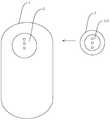
- FIG. 1is a schematic structural diagram of a protective cover of an electronic device 5 of a replaceable function module 4 according to an embodiment of the present invention.
- a protective cover for an electronic device 5 of a replaceable functional module 4 according to an embodiment of the present inventionincludes a protective cover body 1 , and further includes: a protective cover body 1 disposed on the protective cover body 1 for use with the electronic device 5 electrically connected connection contacts 2, a universal carrier module 3 and a functional module 4 detachably arranged on the universal carrier module 3, said functional module 4 being connected to the connection contact 2.
- the technical solution provided by the embodiment of the present inventiononly needs to replace the functional module 4 or the sensor on the universal carrier module 3 and then connect to the connection contact 2 by providing the contact connection 2 of the electric shock type connection on the protective cover body 1.
- the function of the function module 4can be realized by connecting the contacts 2 to realize the docking and operation of the various functional modules 4 and the electronic device 5.
- connection contact 2is arranged through a protective sleeve, one end of the connection contact 2 is for connecting the electronic device 5, and the other end of the connection contact 2 is for connecting a functional module 4.
- the function of the functional module 4is realized by the connection of the connection contact 2 that is electrically connected to the electronic device 5 in the protective cover body 1 and the connection of the connection contact 2 to the functional module 4 .
- the function module 4can be replaced as needed to achieve the desired function.
- the connecting contacts 2are respectively disposed on the inner side and the outer side of the protective cover, the connecting contact 2 disposed near the inner side of the protective cover and the connecting contact 2 disposed near the outer side of the protective cover Electrical connection.
- FIG. 2is a schematic structural diagram of the functional module 4 being a protective cover of the LED lamp module 410.
- the function module 4is an LED lamp module 410.
- the rear LED light module 410can emit various flashes to remind the user of the incoming call display. For example, the red indicator light is the father, the green indicator light is the mother, and the yellow indicator light is the SMS reminder.
- FIG. 3is a schematic structural diagram of the functional module 4 being a protective cover of the gravity sensing module 420.
- the function module 4is a gravity sensing module 420 .
- the gravity sensing module 420is added to be connected to the electronic device 5 through the connection contact 2, thereby implementing an electronic scale-like function, and then the weighing experience operation can be simulated after replacing the module (for example, after the child replaces the module)
- the weighing experiencecan be simulated by an adult, and the specific weighing index is displayed on the screen of the electronic device 5 protected by the protective cover.
- FIG. 4is a schematic structural diagram of the functional module 4 being a protective cover of the temperature sensing module 430.
- the function module 4is a temperature sensing module 430.
- the temperature sensing module 430is added to connect to the electronic device 5 through the connection contact 2 to realize the function of measuring the body temperature.
- the displaycan be displayed on the machine screen. Child's temperature and / or normal body temperature indicators.
- FIG. 5is a schematic structural view of the protective module of the small fan 440 of the function module 4.
- the function module 4is a small fan 440.
- the power supply of the electronic device 5 protected in the protective coveris powered by the power supply.
- the small fan functioncan be realized, and the certain playability is increased.
- FIG. 6is a schematic structural view of the functional module 4 as a protective cover of the clip 450.
- the function module 4is a clip 450.
- the electronic device 5can be a learning machine or a dot reading machine. Of course, it can also be other mobile intelligent electronic devices 5 such as IPAD.
Landscapes
- Engineering & Computer Science (AREA)
- Microelectronics & Electronic Packaging (AREA)
- Casings For Electric Apparatus (AREA)
Abstract
Description
Translated fromChinese本专利申请要求于2015年1月12日提交的,申请号为201510014664.8,申请人为广东小天才科技有限公司,发明名称为“一种可更换功能模块的电子设备保护套”的中国专利申请的优先权,该申请的全文以引用的方式并入本申请中。This patent application is filed on January 12, 2015, and the application number is 201510014664.8. The applicant is Guangdong Xiaotiancai Technology Co., Ltd., and the Chinese patent application titled “Electronic Equipment Cover for Replaceable Function Modules” is preferred. The entire contents of this application are incorporated herein by reference.
本发明涉及电子设备技术领域,尤其涉及一种可更换功能模块的电子设备保护套。The present invention relates to the field of electronic device technologies, and in particular, to an electronic device protective cover for a replaceable functional module.
目前市面上的电子设备(例如电动玩具)往往具有多配件,但是,这些电子设备不能基于多配件形式形成多种不同的功能。Electronic devices currently on the market (such as electric toys) tend to have multiple accessories, but these electronic devices cannot form many different functions based on multiple accessory forms.
发明内容Summary of the invention
本发明的目的在于提供一种可更换功能模块的电子设备保护套,通过增加保护套上的设备模块,实现多种功能。It is an object of the present invention to provide an electronic device protective cover for a replaceable functional module, which realizes various functions by adding a device module on the protective cover.
为达此目的,本发明实施例采用以下技术方案:To achieve this goal, the embodiment of the present invention adopts the following technical solutions:
一种可更换功能模块的电子设备保护套,包括保护套本体,还包括:设置在保护套本体上用于与所述电子设备电性连接的连接触点、通用载体模块以及设置在通用载体模块上的可拆卸功能模块,所述功能模块与连接触点连接。An electronic device protective cover for a replaceable functional module, comprising a protective cover body, further comprising: a connecting contact disposed on the protective cover body for electrically connecting with the electronic device, a universal carrier module, and a universal carrier module The detachable function module is connected to the connection contact.
所述连接触点贯穿保护套设置,所述连接触点的一端用于连接所述电子设备,所述连接触点的另一端用于连接功能模块。The connecting contact is disposed through the protective sleeve, one end of the connecting contact is used to connect the electronic device, and the other end of the connecting contact is used to connect the functional module.
所述连接触点分别设置在保护套的内侧面与外侧面,靠近保护套内侧面设置的连接触点与靠近保护套外侧面设置的连接触点电性连接。The connecting contacts are respectively disposed on the inner side and the outer side of the protective sleeve, and the connecting contacts disposed near the inner side of the protective sleeve are electrically connected to the connecting contacts disposed near the outer side of the protective sleeve.
所述功能模块可以为发光二极管(LED,Light Emitting Diode)灯模块。The function module can be a light emitting diode (LED) light module.
所述功能模块可以为重力感应模块。The function module can be a gravity sensing module.
所述功能模块可以为温度感应模块。The function module can be a temperature sensing module.
所述功能模块可以为小型风扇。The functional module can be a small fan.
所述功能模块可以为夹子。The functional module can be a clip.
所述电子设备可以为学习机或者点读机。The electronic device can be a learning machine or a dot reading machine.
本发明实施例提供一种可更换功能模块的电子设备保护套,包括保护套本体,还包括:设置在保护套本体上用于与所述电子设备电性连接的连接触点、通用载体模块以及设置在通用载体模块上的可拆卸功能模块,所述功能模块与连接触点连接。通过在保护套本体上设置触电式连通的连接触点,只需要更换通用载体模块上的功能模块或感应器,然后连接到连接触点,通过连接触点实现各种功能模块与所述电子设备的对接与操作,即可实现此功能模块的所属功能。An embodiment of the present invention provides an electronic device protective cover for a replaceable functional module, including a protective cover body, and further comprising: a connecting contact disposed on the protective cover body for electrically connecting with the electronic device, a universal carrier module, and A detachable function module disposed on the universal carrier module, the functional module being coupled to the connection contact. By providing an electrically-connected connection contact on the cover body, only the function module or the sensor on the universal carrier module needs to be replaced, and then connected to the connection contact, and various functional modules and the electronic device are realized by the connection contact. The docking and operation can realize the function of this function module.
图1是本发明实施例提供的一种可更换功能模块的电子设备保护套的结构示意图。FIG. 1 is a schematic structural diagram of an electronic device protective cover of a replaceable function module according to an embodiment of the present invention.
图2是功能模块为LED灯模块的保护套的结构示意图。2 is a schematic structural view of a protective cover of the LED lamp module.
图3是功能模块为重力感应模块的保护套的结构示意图。FIG. 3 is a schematic structural diagram of a protective cover of a gravity sensing module.
图4是功能模块为温度感应模块的保护套的结构示意图。4 is a schematic structural view of a protective cover of a temperature sensing module.
图5是功能模块为小型风扇的保护套的结构示意图。FIG. 5 is a schematic structural view of a protective cover of a small fan.
图6是功能模块为夹子的保护套的结构示意图。FIG. 6 is a schematic structural view of a protective cover of a functional module as a clip.
图中:In the picture:
1-保护套本体;2-连接触点;3-通用载体模块;4-功能模块;5-电子设备;410-LED灯模块;420-重力感应模块;430-温度感应模块;440-小型风扇;450-夹子。1- protective cover body; 2-connection contact; 3-general carrier module; 4-function module; 5-electronic device; 410-LED lamp module; 420-gravity sensing module; 430-temperature sensing module; 440-small fan ;450-clip.
下面结合附图并通过具体实施方式来进一步说明本发明的技术方案。The technical solution of the present invention will be further described below with reference to the accompanying drawings and specific embodiments.
图1是本发明实施例提供的一种可更换功能模块4的电子设备5的保护套的结构示意图。如图1所示,本发明实施例提供的一种可更换功能模块4的电子设备5的保护套,包括保护套本体1,还包括:设置在保护套本体1上用于与所述电子设备5电性连接的连接触点2、通用载体模块3以及可拆卸设置在通用载体模块3上的功能模块4,所述功能模块4与连接触点2连接。FIG. 1 is a schematic structural diagram of a protective cover of an
可见,本发明实施例提供的技术方案通过在保护套本体1上设置触电式连通的连接触点2,只需要更换通用载体模块3上的功能模块4或感应器,然后连接到连接触点2,通过连接触点2实现各种功能模块4与所述电子设备5的对接与操作,即可实现此功能模块4的所属功能。It can be seen that the technical solution provided by the embodiment of the present invention only needs to replace the functional module 4 or the sensor on the
作为一种优选地实施方式,所述连接触点2贯穿保护套设置,所述连接触点2的一端用于连接所述电子设备5,所述连接触点2的另一端用于连接功能模块4。通过在保护套本体1内置与所述电子设备5触电式连接的连接触点2,并使连接触点2与功能模块4连接,以实现所述功能模块4的所属功能。并且,可以根据需要,更换功能模块4以达到所需的功能。As a preferred embodiment, the
作为另一种优选的实施方式,所述连接触点2分别设置在保护套的内侧面与外侧面,靠近保护套内侧面设置的连接触点2与靠近保护套外侧面设置的连接触点2电性连接。As another preferred embodiment, the connecting
图2是功能模块4为LED灯模块410的保护套的结构示意图。如图2所示,所述功能模块4为LED灯模块410。当保护套所保护的电子设备5有来电时,后置的LED灯模块410可发出各种闪光,以提醒用户来电显示。例如红色指示灯亮为父亲,绿色指示灯为母亲,黄色指示灯为短信提醒等。FIG. 2 is a schematic structural diagram of the functional module 4 being a protective cover of the
图3是功能模块4为重力感应模块420的保护套的结构示意图。如图3所示,所述功能模块4为重力感应模块420。增加重力感应模块420,使之通过连接触点2与所述电子设备5连接,从而实现类似电子称的功能,进而在更换此模块后可以模拟称重体验操作(例如,儿童在更换此模块后可以模拟大人进行称重体验操作),在保护套所保护的电子设备5的屏幕上显示具体称重指数。FIG. 3 is a schematic structural diagram of the functional module 4 being a protective cover of the
图4是功能模块4为温度感应模块430的保护套的结构示意图。如图4所示,所述功能模块4为温度感应模块430。增加温度感应模块430,使之通过连接触点2与所述电子设备5连接后实现测量身体温度功能,当温度感应模块430紧贴额头一定的时间后,譬如3分钟,可在机器屏幕显示检测儿童的体温和/或正常身体温度指标。FIG. 4 is a schematic structural diagram of the functional module 4 being a protective cover of the
图5是功能模块4为小型风扇440的保护套的结构示意图。如图5所示,所述功能模块4为小型风扇440。增加小型风扇440后,通过保护套内所保护的电子设备5电源为其供电,在保护套后置触点连通后,可实现小风扇功能,增加一定可玩性。FIG. 5 is a schematic structural view of the protective module of the
图6是功能模块4为夹子450的保护套的结构示意图。如图6所示,所述功能模块4为夹子450。通过增加夹子450,能方便地实现电子设备5在适当地方的简单挂置,方便携带。FIG. 6 is a schematic structural view of the functional module 4 as a protective cover of the
在本方案中,所述电子设备5可以为学习机或者点读机。当然,也可以为IPAD等其他可移动智能电子设备5。In the present solution, the
需要说明的是,本发明技术方案的延展性较高,可根据不同的感应器和各种功能模块4实现不同的功能操作,以满足用户在针对不同场景时的不同需求。It should be noted that the technical solution of the present invention has high scalability, and different functional operations can be implemented according to different sensors and various functional modules 4 to meet different needs of users in different scenarios.
以上所述,仅为本发明较佳的具体实施方式,但本发明的保护范围并不局限于此,任何熟悉本技术领域的技术人员在本发明揭露的技术范围内,根据本发明的技术方案及其发明构思加以等同替换或改变,都应涵盖在本发明的保护范围之内。The above is only a preferred embodiment of the present invention, but the scope of the present invention is not limited thereto, and any technical person skilled in the art within the technical scope disclosed by the present invention, the technical solution according to the present invention Equivalent substitutions or modifications of the inventive concept are intended to be included within the scope of the invention.
Claims (9)
Translated fromChineseApplications Claiming Priority (2)
| Application Number | Priority Date | Filing Date | Title |
|---|---|---|---|
| CN201510014664.8ACN104544852A (en) | 2015-01-12 | 2015-01-12 | Electronic equipment protective sleeve with replaceable functional module |
| CN201510014664.8 | 2015-01-12 |
Publications (1)
| Publication Number | Publication Date |
|---|---|
| WO2016112872A1true WO2016112872A1 (en) | 2016-07-21 |
Family
ID=53062754
Family Applications (1)
| Application Number | Title | Priority Date | Filing Date |
|---|---|---|---|
| PCT/CN2016/074071CeasedWO2016112872A1 (en) | 2015-01-12 | 2016-02-18 | Electronic device protective case capable of changing function modules |
Country Status (2)
| Country | Link |
|---|---|
| CN (1) | CN104544852A (en) |
| WO (1) | WO2016112872A1 (en) |
Families Citing this family (1)
| Publication number | Priority date | Publication date | Assignee | Title |
|---|---|---|---|---|
| CN104544852A (en)* | 2015-01-12 | 2015-04-29 | 广东小天才科技有限公司 | Electronic equipment protective sleeve with replaceable functional module |
Citations (5)
| Publication number | Priority date | Publication date | Assignee | Title |
|---|---|---|---|---|
| US20090268402A1 (en)* | 2001-11-21 | 2009-10-29 | William Robert Hanson | Multifunctional cover integrated into sub-panel of portable electronic device |
| CN103491207A (en)* | 2013-08-15 | 2014-01-01 | 金硕澳门离岸商业服务有限公司 | Mobile terminal protective device |
| CN203524035U (en)* | 2013-11-16 | 2014-04-09 | 郑瑛 | Mobile terminal device protecting sleeve |
| CN204031641U (en)* | 2014-05-21 | 2014-12-17 | 深圳市非凡创新实业有限公司 | Multi-functional protective shell |
| CN104544852A (en)* | 2015-01-12 | 2015-04-29 | 广东小天才科技有限公司 | Electronic equipment protective sleeve with replaceable functional module |
Family Cites Families (5)
| Publication number | Priority date | Publication date | Assignee | Title |
|---|---|---|---|---|
| CN101278775A (en)* | 2007-04-04 | 2008-10-08 | 黄国书 | Notebook computer protection bag |
| CN201248451Y (en)* | 2008-07-22 | 2009-06-03 | 文峰 | Buckle for a detachable protective sleeve |
| CN103198340B (en)* | 2012-09-30 | 2017-06-06 | 理康互联科技(北京)有限公司 | Reading/writing of information equipment |
| CN203028382U (en)* | 2012-12-20 | 2013-07-03 | 中国计量学院 | Lighting sheath of remote control |
| US20140233181A1 (en)* | 2013-02-21 | 2014-08-21 | Donn K. Harms | Protective Case Device with Interchangeable Faceplate System |
- 2015
- 2015-01-12CNCN201510014664.8Apatent/CN104544852A/enactivePending
- 2016
- 2016-02-18WOPCT/CN2016/074071patent/WO2016112872A1/ennot_activeCeased
Patent Citations (5)
| Publication number | Priority date | Publication date | Assignee | Title |
|---|---|---|---|---|
| US20090268402A1 (en)* | 2001-11-21 | 2009-10-29 | William Robert Hanson | Multifunctional cover integrated into sub-panel of portable electronic device |
| CN103491207A (en)* | 2013-08-15 | 2014-01-01 | 金硕澳门离岸商业服务有限公司 | Mobile terminal protective device |
| CN203524035U (en)* | 2013-11-16 | 2014-04-09 | 郑瑛 | Mobile terminal device protecting sleeve |
| CN204031641U (en)* | 2014-05-21 | 2014-12-17 | 深圳市非凡创新实业有限公司 | Multi-functional protective shell |
| CN104544852A (en)* | 2015-01-12 | 2015-04-29 | 广东小天才科技有限公司 | Electronic equipment protective sleeve with replaceable functional module |
Also Published As
| Publication number | Publication date |
|---|---|
| CN104544852A (en) | 2015-04-29 |
Similar Documents
| Publication | Publication Date | Title |
|---|---|---|
| US20180368564A1 (en) | Toothbrush base and tooth brushing monitoring system | |
| US20150187187A1 (en) | Wireless visual notification device for mobile device | |
| CN204631389U (en) | A smart glasses with heart rate monitoring function | |
| WO2016112872A1 (en) | Electronic device protective case capable of changing function modules | |
| CN105996370A (en) | Intelligent motion mobile phone sleeve | |
| CN206773311U (en) | With being reminded with eye the intelligent glasses guided are trained with eye movement | |
| CN204218892U (en) | A kind of body temperature monitor | |
| CN202306220U (en) | Vision nursing robot | |
| US10073081B2 (en) | Multi-function alcohol tester | |
| CN202712891U (en) | Electric torch type mobile charger | |
| CN203762512U (en) | Toothbrush | |
| EP3141168B1 (en) | Stir bar for food processor | |
| TWI618891B (en) | A device with detachable lightsource lightguide | |
| CN205175525U (en) | Automatic weigh tealeaves spoon | |
| CN204562982U (en) | A kind of Multifunctional intelligent milk bottle of USB power source heating | |
| CN204274421U (en) | Electronic clinical thermometer | |
| CN207352812U (en) | A kind of changeable colour laser pen | |
| CN103544801A (en) | Maternal-infant safety electronic bracelet | |
| CN205506120U (en) | A multi -functional monitor terminal for colliery | |
| CN203567409U (en) | Pen | |
| CN204838909U (en) | A smart water cup holder | |
| CN216645605U (en) | An infrared and temperature sensing integrated detection pen | |
| KR20130007104U (en) | Wireless Microphone Battery Indicator | |
| CN203954629U (en) | Luminous badminton | |
| CN204179696U (en) | The charging device that a kind of blind person is suitable for |
Legal Events
| Date | Code | Title | Description |
|---|---|---|---|
| 121 | Ep: the epo has been informed by wipo that ep was designated in this application | Ref document number:16737097 Country of ref document:EP Kind code of ref document:A1 | |
| NENP | Non-entry into the national phase | Ref country code:DE | |
| 122 | Ep: pct application non-entry in european phase | Ref document number:16737097 Country of ref document:EP Kind code of ref document:A1 |