WO2016111062A1 - Touch panel and operation determining method - Google Patents
Touch panel and operation determining methodDownload PDFInfo
- Publication number
- WO2016111062A1 WO2016111062A1PCT/JP2015/078406JP2015078406WWO2016111062A1WO 2016111062 A1WO2016111062 A1WO 2016111062A1JP 2015078406 WJP2015078406 WJP 2015078406WWO 2016111062 A1WO2016111062 A1WO 2016111062A1
- Authority
- WO
- WIPO (PCT)
- Prior art keywords
- range
- input
- input point
- erasing
- unit
- Prior art date
- Legal status (The legal status is an assumption and is not a legal conclusion. Google has not performed a legal analysis and makes no representation as to the accuracy of the status listed.)
- Ceased
Links
Images


Classifications
- G—PHYSICS
- G06—COMPUTING OR CALCULATING; COUNTING
- G06F—ELECTRIC DIGITAL DATA PROCESSING
- G06F3/00—Input arrangements for transferring data to be processed into a form capable of being handled by the computer; Output arrangements for transferring data from processing unit to output unit, e.g. interface arrangements
- G06F3/01—Input arrangements or combined input and output arrangements for interaction between user and computer
- G06F3/03—Arrangements for converting the position or the displacement of a member into a coded form
- G06F3/041—Digitisers, e.g. for touch screens or touch pads, characterised by the transducing means
- G06F3/044—Digitisers, e.g. for touch screens or touch pads, characterised by the transducing means by capacitive means
- G06F3/0446—Digitisers, e.g. for touch screens or touch pads, characterised by the transducing means by capacitive means using a grid-like structure of electrodes in at least two directions, e.g. using row and column electrodes
Definitions
- the present inventionrelates to a touch panel having a function of erasing a part of an image displayed on a display screen in response to a user's touch operation.
- Patent Document 1two coordinate indicating units are provided in a rectangular parallelepiped eraser (input tool dedicated to erasing operation) for instructing deletion of the image displayed on the display screen, and the eraser contacts the display screen.
- a technique for erasing an image of an area corresponding to a movement locus of an eraserby making a rectangular area with the two coordinate designation parts at both ends of a diagonal as an erasable area when moving the lens continuously and moving it. .
- Japanese Patent PublicationJapanese Patent Application Laid-Open No. 8-263212 (October 11, 1996).
- Patent Document 1there is a problem that usability is poor because it is necessary to use an input device dedicated to the erasing operation when the user performs the erasing operation on the display screen.
- the present inventionhas been made in view of the above-described problems, and an object thereof is to provide a touch panel which can easily perform an erasing operation.
- a touch panelincludes a large number of detection points arranged on a display screen, and detects a touch operation of a user on the display screen by detecting contact or proximity of an object to each detection point.
- An input point detection unitfor detecting a touch-operated detection point as an input point; and an erasing operation for erasing an image displayed on the display screen by a user operation according to the degree of density of the input points.
- an erasing operation determination unitthat determines whether or not.
- the userchanges the area of the touch operation on the display screen to change the density of the input points, thereby determining whether the user's operation is the erasing operation or an operation other than the erasing operation. It can be determined automatically. Therefore, as in the prior art, when performing the erasing operation, it is not necessary to perform in advance an operation specifying that the touch operation to be performed next is the erasing operation, or to use an input device dedicated to the erasing operation. The erasing operation can be easily performed.
- Embodiment 1One embodiment of the present invention will be described.
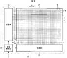
- FIG. 1is an explanatory view showing the overall configuration of a drawing apparatus 100 according to the present embodiment.
- the drawing device 100includes a display device 1, a touch panel 2, and an information processing device 3.
- the information processing device 3outputs image data to be displayed to the display device 1, and acquires, from the touch panel 2, information corresponding to a user's touch operation (operation input) on the display screen on which the image data is displayed. Further, the information processing device 3 updates the image data to be output to the display device 1 based on the information according to the touch operation of the user acquired from the touch panel 2 or performs various processing according to the touch operation of the user .
- the configuration of the information processing device 3is not particularly limited, and may be, for example, a personal computer.
- the display device 1includes a display unit 11, a display drive unit 12, and a display control unit 13.
- the display unit 11displays an image according to the image data acquired from the information processing device 3 on the display screen, and may use, for example, a liquid crystal display, an organic EL (electro luminescence) display, a plasma display, a projector, etc. it can.
- the resolution and size of the display unit 11are not particularly limited, and may be, for example, a full high-vision size of 1920 pixels ⁇ 1080 pixels, or a 4K size of 3840 pixels ⁇ 2160 pixels.
- the display driving unit 12drives each pixel of the display unit 11 according to an instruction from the display control unit 13.
- the display control unit 13controls the operation of the display drive unit 12 according to the image data to be displayed, and causes the display unit 11 to display an image according to the image data.
- the touch panel 2includes a panel unit 21, a panel drive unit 22, and a touch panel control unit 23.
- FIG. 2is an explanatory view showing the configuration of the panel unit 21 and the panel drive unit 22. As shown in FIG. 2
- the panel unit 21is disposed so as to overlap the display screen of the display device 1 and has a function of outputting to the panel drive unit 22 a signal corresponding to an instruction input from the user on the image displayed on the display unit 11.
- the panel unit 21has a plurality of drive lines (drive lines) DL arranged in parallel to one another and a plurality of sense lines (sense lines) SL arranged in parallel to one another.
- the drive line DLextends in the X direction (horizontal direction in the drawing)
- the sense line SLextends in the Y direction (vertical direction in the drawing) orthogonal to the X direction
- the drive line DL and the sense line SLthree-dimensionally intersect. Are arranged (arranged in a matrix).
- the number of drive lines DL and sense lines SLis not particularly limited, but in the present embodiment, 4096 drive lines DL and 2160 sense lines SL are provided, and each of 4096 ⁇ 2160 coordinate positions is provided. Is designed to detect changes in capacitance. Further, the configuration of the panel unit 21 is not limited to the above-described configuration, and various panel units conventionally used in a capacitive touch panel can be used.
- the panel drive unit 22includes a transmission unit 24, a reception unit 25, and a drive control unit 26.
- the drive control unit 26controls operation timings of the transmission unit 24 and the reception unit 25.
- the transmission unit 24sequentially applies the drive signal Ds to each drive line DL at a timing according to a predetermined frame rate at a timing according to an instruction of the drive control unit 26.
- the receiving unit 25acquires the sense signal Ss, which is a response signal generated in each sense line SL in response to the application of the drive signal Ds to each drive line DL, at a timing synchronized with the application of the drive signal Ds to each drive line DL. Do.
- the receiving unit 25outputs a signal corresponding to the capacitance of each intersection of the drive line DL and the sense line SL and a signal indicating the position of each intersection to the touch panel control unit 23 (input point detection unit 31).
- the touch panel control unit 23includes an input point detection unit 31, an erasing operation determination unit 32, and an input information output unit 33.
- the input point detection unit 31generates electrostatics based on a signal corresponding to the capacitance of each intersection of the drive line DL and the sense line SL acquired from the panel drive unit 22 and a signal indicating the position of each intersection.
- An intersection where the capacitance differs from another intersection by a predetermined value or moreis detected as a touch operation position (input point) on the panel unit 21 by the user.
- detection of the touch operation position for one screen of the display screenis processing of one frame, processing of each frame is performed at a predetermined cycle, and the touch operation position is detected for each frame. Thereby, movement of the touch operation position between consecutive frames is detected for each frame.
- the erasing operation determining unit 32includes an area setting unit 34, an input point counting unit 35, a mode determining unit 36, and an erasing range setting unit 37, and based on the input points detected by the input point detecting unit 31, the user It is determined whether the performed touch operation is an erasing operation (an operation for erasing an image in a range corresponding to the touch operation in the image displayed on the display unit 11). Further, when determining that the touch operation performed by the user is the erasing operation, the erasing operation determination unit 32 sets the erasing range according to the touch operation of the user. The details of these processes in the erasing operation determination unit 32 will be described later.
- the input information output unit 33outputs, to the information processing apparatus 3, information according to the touch operation by the user detected by the input point detection unit 31 and the determination result of the deletion operation determination unit 32.
- the erasing operation determination unit 32determines that the erasing operation is performed, the information indicating that the erasing operation is performed and the information indicating the erasing range are output to the information processing device 3. Further, when the erasing operation determination unit 32 determines that the erasing operation is not performed, the information indicating that the erasing operation is not performed and the information indicating the touch operation position of the user are output to the information processing device 3.
- the information processing device 3changes an image to be displayed on the display device 1 according to the touch operation of the user, or performs various processing according to the touch operation.
- the information processing device 3erases the image in the erasing range.
- the information processing apparatus 3may display an image (for example, a frame image) indicating the shape of the erase range at a position corresponding to the user's touch operation. .
- the information processing device 3executes menu processing according to the touch operation.
- the touch operation by the useris not the erasing operation and the touch operation position is the drawing area
- the information processing device 3executes the drawing process.
- drawing processfor example, drawing is performed by connecting the coordinates of the touch operation position detected for each frame with a straight line or a curve.
- a storage unit(not shown) included in the display device 1.
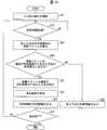
- FIG. 3is a flowchart showing a flow of detection processing of an instruction input from the user on the touch panel 2.
- the input point detection unit 31receives an input point (by the user)
- the touch operation positionis detected (S1).
- the input point detection unit 31detects, as an input point, an intersection where the capacitance differs from another intersection (or a predetermined reference value) by a predetermined value or more.
- the region setting unit 34sets one of the input points detected in S1 as a target input point (S2), and sets a region of a predetermined range centered on the target input point as a search range of the input point To do (S3).
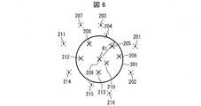
- the region setting unit 34is a circle 301 having a radius R1 (in the present embodiment, the radius R1 is 70 mm) centered on the target input point (the input point 209 in the example of FIG. 6). Is set as the search range.
- the size of the radius R1is not limited to 70 mm, and may be appropriately set according to, for example, the size of the user's hand.
- the radius R1may be set to an area smaller than the size of a standard user's palm (for example, 30 mm or more and 150 mm or less).
- the radius R1may be set to the radius of a circle including the user's index finger, middle finger, ring finger and little finger.
- the input point counting unit 35counts the number of input points included in the search range set in S3 (S4). For example, in the example of FIG. 6, six input points of the input points 205, 206, 208, 210, 212, and 213 are counted.
- the region setting unit 34determines, among all the input points detected in S1, whether or not there remain unprocessed input points not subjected to the processing of S2 to S4 with the input point as the target input point. If it is determined (S5) that there are unprocessed input points, one of the unprocessed input points is used as the target input point to perform the processing of S2 to S4.
- the mode determination unit 36determines whether the user's touch operation is an erasing operation according to the counting result in the process of S4 for each input point. It is determined (S6). That is, the mode determination unit 36 determines whether the user's touch operation is an erase operation according to the density of the input points.
- the mode determination unit 36determines that the delete operation is performed when the number of target input points whose number of input points included in the search range is equal to or greater than the first predetermined number N1 is equal to or greater than a predetermined threshold. If it is less than the threshold value, it is determined that the erasing operation is not performed.
- the first predetermined number N1is not particularly limited, the first predetermined number N1 is larger than the number of fingers in order to appropriately distinguish between touch operations with a finger or a pen and touch operations with a palm or back of a hand. It is preferable to set it as the above.
- the threshold valueis not particularly limited, and may be set appropriately in consideration of the actual size of the panel unit 21, the size of the user's hand, and the like.
- the erase range setting unit 37sets an integrated determination range of the input points (S7).
- the erasing range setting unit 27sets the input point at which the value counted in the process of S4 is the maximum (reference position) as a center (reference position) to determine whether or not the erasing operation is performed.
- a range which is the same as the search range (circle 301) or wider than the search range (circle 301)is set as the integrated determination range.
- the size of the radius R2is not limited to 150 mm, and may be appropriately set according to, for example, the size of the user's hand.
- the radius R2may be set to be a circle that covers the entire palm (or back) of the user. Also, it may be set to about twice the search range. By setting the integrated determination range wider than the search range, the influence of noise can be reduced when setting the deletion range, and the deletion range can be set stably.
- the input point at which the count value in S4 is the largestis set as the center (reference position) of the integrated determination range (circle 401), but the present invention is not limited to this.
- the center of gravity (average value of coordinate values) of each input point determined that the number of input points included in the search range at S6 is the first predetermined number N1 or more, or the input point closest to the centeris integrated judgment range It may be used as the center (reference position) of
- the erasing range setting unit 27determines an input point included in the integrated determination range set in S7 among the input points detected in S1 as an input point (an input point included in the erasing range) to be integrated into the erasing range. (S8).
- the erasure range setting unit 27sets the erasure range based on each input point determined in S8 (S9).
- the X coordinate maximum value, the X coordinate minimum value, the Y coordinate maximum value, and the Y coordinate minimum valueare extracted from the coordinates of each input point determined in S8, and are specified by the extracted coordinate values.
- Rectangular area[x coordinate minimum value, y coordinate minimum value], [x coordinate minimum value, y coordinate maximum value], [x coordinate maximum value, y coordinate minimum value], [x coordinate maximum value, y coordinate maximum value]
- the area of the rectangle 501(rectangle 501 circumscribing the area 402) including the area (closed curve area) 402 formed by connecting the input points determined in S8 is erased. Set as a range.
- the width 503 in the X-axis direction of the rectangle 501is represented by the difference between the X-coordinate maximum value and the X-coordinate minimum value
- the width 504 in the Y-axis directionis represented by the difference between the Y-coordinate maximum value and the Y-coordinate minimum value.
- coordinates 502 shown in FIG. 8indicate center coordinates of the rectangle 501 or barycentric coordinates of the area 402.
- the center coordinates of the rectangle 501can be determined by ((X coordinate minimum value + X coordinate maximum value) / 2, (Y coordinate minimum value + Y coordinate maximum value) / 2), and the barycentric coordinates of the area 402 are determined in S8. It can be determined from the average value of the coordinate values of each input point.
- the input information output unit 33outputs, to the information processing device 3, the information indicating that the erasing operation is performed and the information indicating the erasing range (S10).
- the reference position (for example, the center coordinates) of the rectangle 501, the width 503 in the X axis direction, and the width 504 in the Y axis directionare output.
- the X coordinate maximum value, the X coordinate minimum value, the Y coordinate maximum value, and the Y coordinate minimum value of the deletion range of the rectangular shapemay be output.
- the coordinates of each corner of the rectangular shaped erasing rangemay be output.
- the shape of the erasing rangeis a rectangular shape. This makes it possible to simplify the calculation process of the erasure range in the information processing device 3.
- the shape of the erasing rangeis not limited to this, and may be set to, for example, a circle or an ellipse including the above-mentioned region (closed curve region) 402, and a closed curve formed by connecting each input point determined in S8.
- An area(area 402 shown in FIGS. 7 and 8) may be set as the erasing range.
- the input information output unit 33converts the information indicating the deletion range into coordinate values of the coordinate system according to the resolution of the display unit 11. It may be output to the device 3.
- the input information output unit 33outputs the information indicating the deletion range to the information processing device 3 as the coordinate value of the coordinate system according to the resolution of the panel unit 21, and the information processing device 3 outputs the resolution of the display unit 11 as necessary. It may be converted to a coordinate system according to.
- the touch panel control unit 23determines whether or not the touch operation detection process is ended (S12) If not, the process returns to S1.
- the method of determining whether to end the touch operation detection processis not particularly limited. For example, it may be determined according to whether the user has received a touch operation end instruction or a power off instruction. Alternatively, the determination may be made according to whether or not the state in which the touch operation on the touch panel 2 is not performed has continued for a predetermined time or more.
- the input information output unit 33When it is determined in the process of S6 that the operation is not the erasing operation, the input information output unit 33 outputs the position information of the input point detected in S1 to the information processing device 3 (S11). At this time, information indicating that it is not an erasing operation may be output together with the position information of the input point. Further, when the resolution of the display unit 11 and the resolution of the panel unit 21 are different, the input information output unit 33 converts the position information of the input point into coordinate values of the coordinate system according to the resolution of the display unit 11. It may be output to the device 3.
- the input information output unit 33outputs the position information of the input point to the information processing device 3 as the coordinate value of the coordinate system according to the resolution of the panel unit 21 and the information processing device 3 may resolve the resolution of the display unit 11 as necessary It may be converted to a coordinate system according to.
- the process of S2 to S6is omitted and S11 is omitted. Processing may be performed. This makes it possible to simplify arithmetic processing in the case of not being an erasing operation.
- the touch panel control unit 23determines whether the detection process of the touch operation is ended (S12), and in the case of not ending the process, the process of S1. Return.
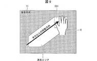
- the erasing operation determination unit 32checks the density of the input points detected as the position touched by the user, and the operation is an erasing operation or an operation other than the erasing operation according to the result. Determine if it is. Further, as shown in FIG. 9, when the user touches the display screen of the display unit 11 (the panel unit 21 of the touch panel 2) with equal hand and moves it on the display screen, the locus of the erasing range is detected for each frame. The information processing apparatus 3 performs the erasing process of the image of the area (erasing area) corresponding to the locus.
- the usercan equalize the hand without performing in advance an operation specifying that the touch operation to be performed next is the deletion instruction as in the above-described prior art or using an input device dedicated to the deletion instruction.
- the erase operationcan be easily input simply by touching the display screen and moving it.
- the size of the erasure rangeis reset in the process of S9 for each frame.
- the range of contact with the display screen (panel unit 21)can be changed according to the range that the user wants to erase, and the range of erasure can be easily adjusted.
- the present inventionis not limited to this, and the size of the erasing range set when it is first determined to be the erasing operation may be maintained constant also in the subsequent erasing operation.
- the number of other input points included in the search range of a predetermined size centered on the input pointcounts the number of input points whose number is equal to or greater than the first predetermined number N1.
- the configurationhas been described in which it is determined whether or not the deletion operation is performed depending on whether or not the number of input points having a first predetermined number N1 or more is a predetermined threshold or more.
- a weighting coefficient according to the distance from the centeris given to the other input points included in the search range of a predetermined size centered on the input point, The sum of the weighting coefficients assigned to each input point is calculated, and whether or not the deletion operation is performed depending on whether or not the number of input points whose calculated value is the first predetermined value V1 or more is the predetermined threshold or more.
- the region setting unit 34sets, as the search range, a circle 301 having a radius R1 centered on the target input point (the input point 209 in the example of FIG. 6) in the process of S3.
- the radius R1is equally divided into N (N is an integer of 2 or more).
- Nis an integer of 2 or more.
- the area closest to the center of the circle 301 (input point 209)is N, and the area closest to the next is N.
- a weighting factoris assigned to the next closest area such as -1, N-2, etc. Note that a weighting factor of 1 is assigned to the farthest area, and a weighting factor of 0 is assigned to an area farther than the radius R1.
- the input point counting unit 35assigns, to each input point, a weighting factor according to the area to which the input point belongs, and calculates a total value of weighting factors assigned to each input point. .
- the mode determination unit 36Whether or not the user's touch operation is an erasing operation is determined according to whether or not the number of input points whose values are greater than or equal to a first predetermined value V1 is greater than or equal to a predetermined threshold. The subsequent processing is the same as that of the first embodiment. That is, the mode determination unit 36 determines whether the user's touch operation is an erase operation according to the density of the input points.
- the size of the search range (circle 301) of the input point set in the process of S3is constant.
- the size of the search range of the input pointis set larger than the search range (circle 301) before it is determined to be the deletion operation during the period in which the deletion operation continues. Do. For example, while the erasing operation continues, the radius of the circle serving as the search range of the input point is twice or more the radius of the original search range (circle 301) before it is determined to be the erasing operation.
- the above-mentioned threshold value for determining whether or not the erasing operation is performed in S6may be set to a value (for example, 1) smaller than the initial threshold value.
- the first predetermined number N1 for evaluating the degree of concentration of the input points in S6is set to a value (for example, 1) smaller than the first predetermined number N1. It may be set.
- the erasing processcan be performed stably.
- Embodiment 4Another embodiment of the present invention will be described.
- symbolis attached
- the size of the integrated determination range (circle 401) set in the process of S8is constant, and the input point included in the integrated determination range in the process of S9 is included in the deletion range.
- the erasing range setting unit 37sets the erasing range of the current (nth frame) during the period in which the erasing operation is continued, the previous (n-1th frame)
- the moving direction of the integrated determination range (circle 401) from the time of setting the deletion rangeis detected, and this is an input point outside the current integrated determination range (circle 401) with respect to the current integrated determination range (circle 401).
- An input point present at a position along the movement directionis included in the current erasure range (rectangle 501).
- the moving direction of the integrated determination rangecan be determined based on, for example, the locus of the reference position of the integrated determination range.
- the input points that exist in the equal movement direction of the user's hand and exist less than a predetermined distance from the integrated determination rangeare S9. While being added to the erasure range in the process of (1), an input point separated by a predetermined distance or more from the integrated determination range may not be included in the erasure range.
- the size of the integrated determination range (circle 401) set in the process of S8is constant, and the input point included in the integrated determination range in the process of S9 is included in the deletion range. Further, the input information output unit 33 outputs the position information of the input point to the information processing device 3 for the input point not included in the integrated determination range.
- Embodiment 4 and the present embodimentare combined, and the input point existing in the uniform movement direction of the user's hand with respect to the integrated determination range is added to the deletion range and the user's equal movement with respect to the integrated determination range Among input points present in directions other than the direction, input points present within a predetermined distance from the integrated determination range may be excluded from the input points and position information may not be output.
- FIG. 11is an explanatory view showing the concept of the method of setting the erasure range in the present embodiment.
- movement vectors(see arrows in the drawing) of each detected input point for each predetermined time are calculated, and each input point whose movement vector is within a predetermined deviation. (Refer to the input point surrounded by a broken line in the figure) is treated as one object, and an area including each of the input points is set as the deletion range.
- FIG. 12is a flowchart showing a flow of detection processing of an instruction input from the user in the present embodiment.
- an input pointtouch operation position
- a signal indicating an electrostatic capacitance at each intersection (detection point) of the drive line DL and the sense line SLwhich is input from the panel drive unit 22.
- the detectionis started every predetermined period (for example, 5 milliseconds) of (S21).
- the detection result of the input pointis temporarily stored in a storage unit (not shown).
- the area setting unit 34monitors that a predetermined time (for example, 0.1 second) has elapsed since the detection process of the input point is started (or since the movement vector was previously calculated) (S22). If it is determined that the movement vector has been determined, the movement vector for each predetermined time (the movement vector from the coordinates of each input point before the elapse of the predetermined time to the coordinates of the input point after the predetermined time has elapsed) is calculated (S23).
- a predetermined timefor example, 0.1 second
- the mode determination unit 36determines whether there is a second predetermined number N 2 or more (for example, two or more) of input points at which the deviation of the movement vector is within a predetermined range (for example, within ⁇ 3 mm in the x direction and y direction) by the mode determination unit 36 It is determined whether or not it is (S24). Then, if it is determined in S24 that the number is the second predetermined number N2 or more, the mode determination unit 36 determines that it is the erasing operation, and if it is determined that it is less than the second predetermined number N2, it is not the erasing operation. Do.
- the erasure range setting unit 37selects input points whose deviation of movement vector is within the predetermined range. Integration (grouping) is performed (S25).
- FIG. 13is an explanatory diagram for describing determination processing as to whether or not it is an erasing operation and setting processing of an erasing range.
- the mode determination unit 36sorts (searches) the x-coordinates and extracts a group of input points having a deviation of 0.3 mm. Thereby, in the example of FIG. 13, the group "P1, P3" and the group “P2, P3, P4, P5" are extracted.
- the mode determination unit 36sorts the y-coordinates for each of the groups extracted based on the x-coordinates, and extracts a group of input points within a deviation of 0.3 mm as in the case of the x-coordinates.
- the group (group 1) of "P1, P3" and the group (group 2) of "P2, P3, P4"are extracted.
- the mode determination unit 36compares, for each group extracted based on the x coordinate and the y coordinate, the number of input points included in each group, and extracts a group having a large number of input points.
- the group 2 having a large number of input pointsis extracted from the groups 1 and 2.
- the mode determination unit 36determines whether the number of input points included in the extracted group (group 2 in the example of FIG. 13) is equal to or greater than the second predetermined number N2, and determines whether the number is equal to or greater than the second predetermined number N2.
- the deletion range setting unit 37integrates the input points included in the group.
- the mode determination unit 36calculates the movement vector of the group based on the average value of the input points included in the group, and as one object You may handle it.
- the newly added input pointis compared with the movement vector of the existing input point (or the movement vector of the integrated group), and the new input It may be determined whether to add the points to the integrated group.
- the movement vector of group 2is GP2. Assuming (1.7, 1.4), P1 and P5 are excluded because they are not within the deviation of ⁇ 0.3 mm, and P6 is within the deviation of ⁇ 0.3 mm for both x and y coordinates. Because it is included in group 2.
- the input points P1 and P5 not included in the group 2are considered as inputs other than the erasing operation.
- the movement vector of the integrated groupis calculated based on, for example, the average value of the coordinate values of the input points included in the group.
- the erasing range setting unit 37After integrating the input points whose deviation of the movement vector is within the predetermined range in S25, the erasing range setting unit 37 sets the erasing range based on the integrated input points (S26).
- the erasure range setting unit 37extracts the X coordinate maximum value, the X coordinate minimum value, the Y coordinate maximum value, and the Y coordinate minimum value from the coordinates of each input point integrated in S25, and extracts these The rectangular area specified by the coordinate values of is set as the deletion range.
- the input information output unit 33outputs, to the information processing device 3, information indicating that the deletion operation is performed and information indicating the deletion range (S27).
- the reference position (for example, the center coordinates) of the rectangle 501, the width 503 in the X axis direction, and the width 504 in the Y axis directionare output.
- the X coordinate maximum value, the X coordinate minimum value, the Y coordinate maximum value, and the Y coordinate minimum value of the deletion range of the rectangular shapemay be output.
- the coordinates of each corner of the rectangular shaped erasing rangemay be output.
- the touch panel control unit 23determines whether the touch operation detection process is to be ended (S29), and if it is not to be ended, the process returns to the process of S22.
- the method of determining whether to end the touch operation detection processis not particularly limited. For example, it may be determined according to whether the user has received a touch operation end instruction or a power off instruction. It may be determined that the touch operation is not performed on the touch panel 2 (when the touch-up is performed), and the state where the touch operation on the touch panel 2 is not performed continues for a predetermined time or more. You may judge according to whether you did.
- the input information output unit 33detects each input point detected in each predetermined cycle.
- the position information ofis output to the information processing apparatus 3 (S28), and the process proceeds to the process of S29.
- an area including each input point whose movement vector for each input point calculated at each predetermined time is within a predetermined deviationis set as the deletion range of the image.
- the input point to be included in the erasing rangecan be determined according to the movement of the input point. Therefore, for example, even when an input operation (such as a drawing operation) different from the erase operation is performed near the erase range, the erase operation and an operation other than the erase operation are appropriately identified to cause an erroneous determination. It can prevent.
- an input operationsuch as a drawing operation
- FIG. 14is an explanatory view showing the concept of the method of setting the erasure range in the present embodiment. As shown in this figure, in this embodiment, a change in distance between adjacent input points in a predetermined period is calculated for each detected input point, and the amount of change in distance is within a second predetermined value V2. Treat input points as one object, and set an area including each input point as an erasing range.
- FIG. 15is a flowchart showing a flow of detection processing of an instruction input from the user in the present embodiment.
- the input point detection unit 31generates a signal for each predetermined period (for example, based on a signal indicating electrostatic capacitance at each intersection (detection point) between the drive line DL and the sense line SL) input from the panel drive unit 22.
- An input point (touch operation position)is detected every 5 milliseconds (S31).
- the detection results of the input pointare sequentially stored in a storage unit (not shown).
- the mode determination unit 36calculates the distance between adjacent input points (see the arrow in FIG. 14) for each input point detected in S31 this time (S32).
- the calculation result of the distanceis sequentially stored in a storage unit (not shown).
- the mode determination unit 36excludes, from the determination processing whether or not the input point whose distance to the adjacent input point is a predetermined determination value (for example, 15 cm) or more is the erasing operation (S33).
- a predetermined determination valuefor example, 15 cm
- the mode determination unit 36determines whether a predetermined period (for example, 50 milliseconds) has elapsed since the detection of the input point is continuously started (S34). When it is determined that the predetermined period has not elapsed, the process returns to the process of S31.
- a predetermined periodfor example, 50 milliseconds
- the mode determination unit 36sets the third input point whose fluctuation range of the distance to the adjacent input point in the predetermined period is equal to or less than the second predetermined value V2 (for example, 2 mm). It is determined whether there is a predetermined number N3 (for example, two) or more (S35). Then, if it is determined in S35 that the number is the third predetermined number N3 or more, the mode determination unit 36 determines that the deletion operation is performed, and if it is determined that the third predetermined number N3 is less than N3, it is not the deletion operation. to decide.
- the erasure range setting unit 37determines each input for which the fluctuation range of the distance to the adjacent input point is less than or equal to the second predetermined value V2. Integrate the points (S36).
- FIG. 16is an explanatory view for explaining determination processing of whether or not an erasing operation and setting processing of an erasing range, where (a) is a coordinate detection value for each predetermined cycle of each input point, and (b) is a predetermined cycle. The distance between each adjacent input point, and (c) indicates the deletion range set based on each input point.
- the mode determination unit 36determines, for each predetermined cycle, whether there is an input point whose distance to an adjacent input point is equal to or greater than a predetermined determination value (for example, 15 cm). If there is an input point, the input point is erased. It is excluded from the judgment processing of the operation.
- a predetermined determination valuefor example, 15 cm
- the mode determination unit 36sorts (searches) each input point based on the x-coordinate value.
- P 3, P 1, P 5, P 2, P 6 and P 4are in ascending order of x-coordinate value. Since the difference between the x-coordinate values of the input point P3 having the smallest x-coordinate value and the input point P4 having the largest x-coordinate value does not exceed the predetermined determination value (15 cm), there is nothing excluded from the determination processing of the erasing operation.
- P2, P4, P1, P3, P6, and P5are arranged in ascending order of y coordinate value, and there is no input point where the difference of y coordinate value exceeds a predetermined judgment value (15 cm) Therefore, there is nothing excluded from the determination processing of the erasing operation.
- the mode determination unit 36determines the distance between adjacent input points (a distance between P3-P1, P1-P5, P5-P2, P2-P6, P6-P4. Calculate).
- the calculation of the distance between the adjacent input pointsis continued during time t1 to t10, while the fluctuation range of the calculated distance (the difference between the minimum value min and the maximum value max) ⁇ max is a second predetermined value V2 (for example, 2 mm) If there is an input point that exceeds the above, the input point is excluded and recalculation is performed. Thereby, in the example of FIG. 16, the input point P2 is excluded.
- the erasing range setting unit 37integrates the input points whose fluctuation range of the distance is equal to or less than the second predetermined value V2 (S36).
- the erasing range setting unit 37integrates the input points whose fluctuation range of the distance is equal to or less than the second predetermined value V2 (S36).
- the deletion range setting unit 37sets the deletion range based on the coordinates of each integrated input point (S37). Specifically, from the coordinates of each integrated input point, the X coordinate maximum value, the X coordinate minimum value, the Y coordinate maximum value, and the Y coordinate minimum value are extracted, and a rectangular area specified by these extracted coordinate values Set to the erase range.
- the input information output unit 33outputs, to the information processing device 3, information indicating that the deletion operation is performed and information indicating the deletion range (S38).
- the touch panel control unit 23determines whether or not the touch operation detection process is to be ended (S40), and if it is not to be ended, the process returns to the process of S31.
- the input information output unit 33When it is determined in the process of S35 that the number of input points whose fluctuation range is less than the second predetermined value V2 is less than the third predetermined number N3 (when it is determined not to be the erasing operation), the input information output unit 33 The position information of the input point detected in S31 is output to the information processing device 3 (S39), and the process proceeds to S40.
- the coordinate of the deletion rangeis calculated based on the coordinate value of each integrated input point detected every predetermined cycle, and the X coordinate maximum at the integrated input point
- the area of the rectangular area specified by the value, the X coordinate minimum value, the Y coordinate maximum value, and the Y coordinate minimum valueis continuously monitored, and the area has changed by a predetermined ratio or more with respect to the area of the erasing range initially set.
- the integration process of the input points and the setting process of the erasure rangemay be performed again.
- the deletion rangecan be appropriately set according to the touch operation.
- the area of the rectangular area A specified by each of the input points P1 and P3 to P6is monitored, and when the change amount of the area of the rectangular area from time t0 becomes equal to or more than a predetermined condition, It is determined that there is an input point at which the distance of the lens greatly fluctuates, and the input point to be integrated is reset.
- the input point P3gradually separates from the other input points, and the area of the rectangular area A gradually increases from the rectangular area A (t0) at time t0 to the rectangular area A (t10) at time t10. Grow in size.
- at least one of the difference between the maximum value and the minimum value of the x coordinate of the integrated input point and the difference between the maximum value and the minimum value of the y coordinateis at least a predetermined value (for example 5 mm) than at time t0.
- the input point to be integratedis recalculated when it becomes large, and the input point P3 is excluded from the integration target.
- the excluded input point P3may not be the input point of the erasing operation but the input point of the drawing operation.
- an area including each input point whose amount of change in the distance between the input points in the predetermined period is within the second predetermined value V2is set as the erasing range.
- the input point to be included in the erasing rangeaccording to the change in the distance between the input points for each predetermined period. Therefore, for example, even when an operation other than the erasing operation is performed near the area subjected to the erasing operation, the erasing operation and the operation other than the erasing operation can be appropriately identified to prevent an erroneous determination. In addition, even when the area subjected to the erasing operation moves in a curved manner instead of a linear movement, an input point to be integrated can be appropriately detected.
- the method of integrating input points according to the above-described sixth embodiment(a method of integrating each input point whose movement vector for each predetermined time of each detected input point is within a predetermined deviation);
- Combining the integration method according to the seventh embodiment(a method of integrating input points whose fluctuation range of distance between adjacent input points within a predetermined period is within a second predetermined value V2 for each detected input point) Use.
- FIG. 18is an explanatory view for explaining determination processing of whether or not it is an erasing operation and setting processing of the erasing range, in which (a) is a coordinate detection value for each predetermined cycle of each input point, and (b) is a predetermined cycle The distance between each adjacent input point, (c) indicates the detected coordinates of each input point, and (d) indicates the movement vector of each input point.
- the input point detection unit 31detects an input point every predetermined cycle (5 milliseconds in the present embodiment). Then, the region setting unit 34 calculates the movement vector of each input point every predetermined time (30 milliseconds which is a period from t1 to t7 in this embodiment), and the mode determination unit 36 determines the deviation of the movement vector within a predetermined range Input points that are outside (for example, outside the range of ⁇ 3 mm in the x direction and y direction, respectively) are excluded from the targets of integration processing. Thereby, in the example of FIG. 18, since the movement vector of the input point P2 is out of the predetermined range as shown in (a), the input point at time t7 as shown in (c) and (d) P2 is excluded from integration processing.
- the mode determination unit 36determines that the deletion operation is not performed when the input point whose deviation of the movement vector is within the predetermined range is less than the second predetermined number N2 (for example, two).
- the mode determination unit 36determines that the predetermined period (50 milliseconds, which is a period from t1 to t10 in this embodiment), is equal to or greater than the second predetermined number N2. Every time e.g. passes, a change in the distance between adjacent input points in the predetermined period is calculated.
- the mode determination unit 36determines that the erasing operation is not performed when the input point whose fluctuation range is equal to or less than the second predetermined value V2 (for example, 2 mm) is less than the third predetermined number N3 (for example, two).
- the mode determination unit 36determines that the erasing operation is performed.
- the erasure range setting unit 37sets, as the erasure range, a region including each input point whose fluctuation range of the distance is within the second predetermined value V2.
- the narrowed input pointsare determined based on the change in the distance between the input points. It is determined whether each input point should be integrated.
- a method of integrating input points according to the sixth embodiment(a method of integrating each input point whose movement vector for each predetermined time of each detected input point is within a predetermined deviation) according to the seventh embodiment. While the calculation is simpler than the integration method (a method of integrating input points in which the fluctuation range of the distance between adjacent input points within a predetermined period for each detected input point is within the second predetermined value V2), The accuracy of the erasure range setting is higher in the integration method according to the seventh embodiment. Therefore, according to the method of the present embodiment, the advantages of both the method of integrating input points according to the sixth embodiment and the method of integration according to the seventh embodiment can be used, and setting of the erasing range is accurately performed by simple calculation. It can be carried out.
- the input pointsare narrowed down by the method of integrating the input points according to the sixth embodiment (a method of integrating the input points whose movement vector for each predetermined time of each detected input point is within a predetermined deviation). After that, the distance between the input points may be calculated, and the input point whose calculated distance is equal to or greater than a predetermined determination value may be excluded from the integration processing target at that time.
- the distance between the input point by the sleeve or the like and the input point by the erasing operationis for the erasing operation Since the distance between the input points is longer than the distance between the input points, it is possible to exclude the input point by the sleeve or the like from the target of integration processing.
- the touch panel control unit 23 of the touch panel 2may be realized by a logic circuit (hardware) formed in an integrated circuit (IC chip) or the like, or software using a CPU (central processing unit) It may be realized by
- the touch panel control unit 23is a CPU that executes an instruction of a program that is software that realizes each function, a ROM (Read Only Memory) in which the program and various data are readably recorded by a computer (or CPU).
- a storage device(these are referred to as “recording media”), a RAM (Random Access Memory) for developing the program, and the like are provided.
- the object of the present inventionis achieved by the computer (or CPU) reading the program from the recording medium and executing the program.
- the recording mediuma “non-transitory tangible medium”, for example, a tape, a disk, a card, a semiconductor memory, a programmable logic circuit or the like can be used.
- the programmay be supplied to the computer via any transmission medium (communication network, broadcast wave, etc.) capable of transmitting the program.
- the present inventioncan also be realized in the form of a data signal embedded in a carrier wave, in which the program is embodied by electronic transmission.
- the touch panel 2includes a large number of detection points arranged on the display screen, and detects a touch operation of the user on the display screen by detecting contact or proximity of an object to each detection point.
- An input point detection unit 31that detects a touch-operated detection point as an input point, and the user operation erases the image displayed on the display screen according to the density of the input points.
- an erase operation determination unit 32that determines whether or not the erase operation is performed.
- the userchanges the area of the touch operation on the display screen to change the density of the input points, whereby the user's operation is an erase operation or an operation other than the erase operation (for example, a drawing operation) Or menu selection operation etc.) can be automatically determined. Therefore, as in the prior art, when performing the erasing operation, it is not necessary to perform in advance an operation specifying that the touch operation to be performed next is the erasing operation, or to use an input device dedicated to the erasing operation. It is possible to easily input the erasing operation.
- the erasing operation determination unit 32sequentially selects and selects the input points detected by the input point detection unit 31 one by one as the target input point.
- An area setting unit 34that sets an area of a predetermined range centered on the target input point as a search range for the target input point, and an input point count that counts the number of input points present in the search range for each target input point.
- the number of other input points present in the predetermined range with respect to the input pointis counted, and the first predetermined number N1 or more of the other input points exist in the predetermined range. If the number of input points to be input is equal to or greater than a threshold value, it is determined that the deletion operation is performed. Thereby, it is possible to appropriately determine whether or not the user's operation is the erasing operation according to the density of the input points.
- the erasing operation determination unit 32sequentially selects and selects the input points detected by the input point detection unit 31 one by one as the target input point.
- An area setting unit 34for setting an area of a predetermined range centered on the target input point as a search range for the target input point, and an input point and a target input point for each input point existing in the search range
- An input point counting unit 35that assigns a weighting factor that decreases as the distance increases and counts the sum of the weighting factors assigned for each input point for each target input point, and the total number counted by the input point counting unit 35
- a mode determination unit 36which determines that the user's operation is the deletion operation when the number of target input points whose number is a first predetermined value V1 or more is equal to or more than a predetermined threshold value. It is configured to have.
- a weighting coefficient that decreases as the distance from the input point to the other input pointincreases with respect to the other input points existing within the predetermined range with respect to the input point. Is determined, and the number of input points whose sum value obtained by summing them is equal to or greater than the first predetermined value V1 is equal to or greater than the value. Thereby, it is possible to appropriately determine whether or not the user's operation is the erasing operation according to the density of the input points.
- the input point among the input points detected by the input point detection part 31 when the mode determination part 36 determines that the deletion operationis performed.
- An area including each input point included in the integrated determination range of a predetermined size having the input point at which the value counted by the point counting unit 35 is maximum as a reference positionis set as an erasing range which is a target range of the image erasing process.
- the configurationis provided with an erasure range setting unit 37.
- the range corresponding to the touch operation of the usercan be set as the deletion range by setting the deletion range according to the input point included in the integrated determination range.
- the input point among the input points detected by the input point detection unit 31 when the mode determination unit 36 determines that the operation is an erasing operationAn area including each input point included in the integrated determination range of a predetermined size having the input point at which the total value counted by the counting unit 35 is maximum is set as an erasing range which is a target range of the image erasing process
- the configurationis provided with an erasure range setting unit 37.
- the range corresponding to the touch operation of the usercan be set as the deletion range by setting the deletion range according to the input point included in the integrated determination range.
- the input point to be included in the deletion rangeis selected based on the result weighted according to the distance between the input points, the change in the input point due to the change of the contact degree with the display screen etc. Even if it occurs, the erasure range can be set appropriately.
- the deletion range setting unit 37sets the size of the integrated determination range to a range wider than the size of the search range.
- the size of the search range for determining whether or not the deletion operation is performedis smaller than the size of the integrated determination range for setting the deletion range when it is determined that the deletion operation is performed.
- the erasing range setting unit 37is a closed curve region surrounded by a closed curve connecting each input point included in the integrated determination range A rectangular, circular, or elliptical area including a closed curve area is set as the erasing range.
- the range corresponding to the touch operation of the usercan be set as the deletion range by setting the deletion range according to the input point included in the integrated determination range.
- the erasing operation determination unit 32determines whether or not the user's operation is an erasing operation at predetermined intervals.
- the area setting unit 34is configured to make the size of the search range larger than the size before the determination that the user first performs the erasing operation after the first determination that the user's operation is the erasing operation. It is.
- the size of the search range to be applied to the process of determining whether or not the operation is a subsequent erasing operationis wider than before it is determined that the operation is an erasing operation. Do. As a result, even when part of the portion (for example, the same hand) touched during the erasing operation temporarily floats from the display screen, the erasing operation can be performed stably.
- the erasing rangeis stabilized even when floating or blurring of the contact position occurs between the input means (for example, a user's hand or an input tool for erasing operation) and the display screen at the time of touch operation. It can be done.
- the deletion operation determination unit 32calculates, for each of the plurality of input points detected by the input point detection unit 31, every input point If there is a second predetermined number N2 or more of input points whose movement vector is within a predetermined deviation, it is determined that the user's operation is an erasing operation, and the erasing operation determination unit 32 determines that the operation is an erasing operation And an erasing range setting unit 37 configured to set an area including the input points whose movement vector is within a predetermined deviation as an erasing range to be an image erasing process. is there.
- the input pointit is possible to determine the input point to be included in the deletion range according to the movement of the input point (the touch point touched by the user). Therefore, for example, even when an input operation (such as a drawing operation) different from the erase operation is performed near the erase range, the erase operation and an operation other than the erase operation are appropriately identified to prevent an erroneous determination from occurring. it can.
- an input operationsuch as a drawing operation
- the erasing operation determination unit 32determines a distance between input points among a plurality of input points detected by the input point detection unit 31 within a predetermined period. When there is a third predetermined number N3 or more of input points whose fluctuation range in the second is within the second predetermined value V2, it is determined that the user operation is the erasing operation, and the erasing operation determination unit 32 determines that the operation is the erasing operation When the area between the input points is within the second predetermined value V2 within the predetermined period, the area including the input points is set as the erasing range which is the target range of the image erasing process.
- the configurationincludes a range setting unit 37.
- the input pointit is possible to determine the input point to be included in the deletion range according to the movement of the input point (the touch point touched by the user). Therefore, for example, even when an input operation (such as a drawing operation) different from the erase operation is performed near the erase range, the erase operation and an operation other than the erase operation are appropriately identified to prevent an erroneous determination from occurring. it can.
- an input operationsuch as a drawing operation
- the erasing operation determination unit 32calculates, for each of the plurality of input points detected by the input point detection unit 31, each input point calculated for each predetermined time.
- a second predetermined number N2 or more of input points whose movement vectors are within a predetermined deviation exist, and an input point whose variation width within a predetermined period of the distance between the input points is within a second predetermined value V2is 3
- the predetermined number N3 or more existsit is determined that the user's operation is an erasing operation, and when the erasing operation determination unit 32 determines that the operation is an erasing operation, the movement vector is within a predetermined deviation.
- an area including each of the input points whose fluctuation range within the predetermined period of the distance between the input points is within the second predetermined value V2is set as the erasing range which is a target range of the image erasing process
- the input pointit is possible to determine the input point to be included in the deletion range according to the movement of the input point (the touch point touched by the user). Therefore, for example, even when an input operation (such as a drawing operation) different from the erase operation is performed near the erase range, the erase operation and an operation other than the erase operation are appropriately identified to prevent an erroneous determination from occurring. it can.
- an input operationsuch as a drawing operation
- the touch panel according to aspect 13 of the present inventionincludes an input information output unit 33 that outputs information according to a user's operation input to the information processing device 3 in any one of the above aspects 4 to 12, and the input information output unit 33.
- the erase operation determination unit 32determines that the erase operation is performed, the information indicating the erase range is output, and when the erase operation determination unit 32 determines that the erase operation is not performed, the input is performed.
- the position information of the input point detected by the point detection unit 31is output.
- the input information output unit 33is detected by the input point detection unit 31 when the erasure operation determination unit 32 determines that the operation is an erasure operation.
- the erasure operation determination unit 32determines that the operation is an erasure operation.
- position information of an input point whose distance from the erasure range is a predetermined distance or moreis output, and position information of an input point less than the predetermined distance is not output. .
- the operation determination methodincludes a large number of detection points arranged on a display screen, and detects a touch operation of a user on the display screen by detecting contact or proximity of an object to each detection point. And an input point detection step of detecting a touch-operated detection point as an input point, and a user operation displayed on the display screen according to the density of the input points. And an erase operation determination step of determining whether the image is an erase operation for erasing the image.
- the userchanges the area of the touch operation on the display screen to change the density of the input points, and thereby the user's operation is an erase operation or an operation other than the erase operation (for example, a drawing operation) Or menu selection operation etc.) can be automatically determined. Therefore, as in the prior art, when performing the erasing operation, it is not necessary to perform in advance an operation specifying that the touch operation to be performed next is the erasing operation, or to use an input device dedicated to the erasing operation. It is possible to easily input the erasing operation.
- the touch panel 2may be realized by a computer.
- the computeris operated as the erasing operation determination unit (software element) included in the touch panel 2 to cause the computer to operate the touch panel.
- the control program of the touch panel realized by the embodiment and the computer readable recording medium recording the sameare also included in the scope of the present invention.
- the present inventioncan be applied to a touch panel having a function of erasing part of an image displayed on a display screen in response to a user's touch operation.
Landscapes
- Engineering & Computer Science (AREA)
- General Engineering & Computer Science (AREA)
- Theoretical Computer Science (AREA)
- Human Computer Interaction (AREA)
- Physics & Mathematics (AREA)
- General Physics & Mathematics (AREA)
- User Interface Of Digital Computer (AREA)
- Position Input By Displaying (AREA)
Abstract
Description
Translated fromJapanese本発明は、表示画面に表示された画像の一部をユーザのタッチ操作に応じて消去する機能を有するタッチパネルに関するものである。The present invention relates to a touch panel having a function of erasing a part of an image displayed on a display screen in response to a user's touch operation.
従来、タッチパネルに対してユーザが表示画面に描画された画像の消去操作を行う方法として、次に行うタッチ操作が消去操作であることを指定する操作を予め行ってから消去操作のためのタッチ操作を行う方法や、消去操作専用の入力器具を用いる方法などが知られている。Conventionally, as a method of performing an erase operation of an image drawn on a display screen by a user on a touch panel, a touch operation for an erase operation after performing in advance an operation specifying that the touch operation to be performed next is an erase operation Are known, and methods using an input device dedicated to the erasing operation are known.
例えば、特許文献1には、表示画面に表示された画像を消去指示するための直方体形状のイレーサ(消去操作専用の入力器具)に2つの座標指示部を設けておき、イレーサを表示画面に接触させて連続的に移動させたときに、上記2つの座標指示部を対角線の両端とした矩形領域を消去可能領域とし、イレーサの移動軌跡に対応する領域の画像を消去する技術が開示されている。For example, in
しかしながら、上記特許文献1の技術では、ユーザが表示画面に対する消去操作を行う際に消去操作専用の入力器具を使用する必要があるので、使い勝手が悪いという問題がある。However, in the technique of
また、次に行うタッチ操作が消去操作であることを指定する操作を予め行ってから消去操作のためのタッチ操作を行う方法では、2段階の操作が必要になるので、手間がかかるという問題がある。In addition, in the method of performing the touch operation for the erasing operation after performing in advance the operation for designating that the touch operation to be performed next is the erasing operation, the operation of two steps is required, and therefore, there is a problem that it takes time and effort. is there.
本発明は、上記の問題点に鑑みて成されたものであり、その目的は、消去操作を容易に行うことができるタッチパネルを提供することにある。The present invention has been made in view of the above-described problems, and an object thereof is to provide a touch panel which can easily perform an erasing operation.
本発明の一態様にかかるタッチパネルは、表示画面上に配置された多数の検知点を備え、各検知点に対する物体の接触または近接を検知することにより前記表示画面に対するユーザのタッチ操作を検出するタッチパネルであって、タッチ操作された検知点を入力点として検出する入力点検出部と、前記入力点の密集度合に応じてユーザの操作が前記表示画面に表示された画像を消去するための消去操作であるか否かを判定する消去操作判定部とを備えていることを特徴としている。A touch panel according to an aspect of the present invention includes a large number of detection points arranged on a display screen, and detects a touch operation of a user on the display screen by detecting contact or proximity of an object to each detection point. An input point detection unit for detecting a touch-operated detection point as an input point; and an erasing operation for erasing an image displayed on the display screen by a user operation according to the degree of density of the input points. And an erasing operation determination unit that determines whether or not.
上記の構成によれば、ユーザが表示画面に対するタッチ操作の面積を異ならせることで入力点の密集度合を変化させ、それによってユーザの操作が消去操作であるのか消去操作以外の操作であるのかを自動的に判定させることができる。したがって、従来技術のように、消去操作を行う場合に、次に行うタッチ操作が消去操作であることを指定する操作を予め行ったり、消去操作専用の入力器具を用いたりする必要がないので、消去操作を容易に行うことができる。According to the above configuration, the user changes the area of the touch operation on the display screen to change the density of the input points, thereby determining whether the user's operation is the erasing operation or an operation other than the erasing operation. It can be determined automatically. Therefore, as in the prior art, when performing the erasing operation, it is not necessary to perform in advance an operation specifying that the touch operation to be performed next is the erasing operation, or to use an input device dedicated to the erasing operation. The erasing operation can be easily performed.
〔実施形態1〕
本発明の一実施形態について説明する。
One embodiment of the present invention will be described.
(1-1.タッチパネルの全体構成)
図1は、本実施形態にかかる描画装置100の全体構成を示す説明図である。図1に示すように、描画装置100は、表示装置1、タッチパネル2、および情報処理装置3を備えている。(1-1. Overall configuration of touch panel)
FIG. 1 is an explanatory view showing the overall configuration of a
情報処理装置3は、表示装置1に表示対象の画像データを出力するとともに、上記画像データが表示された表示画面に対するユーザのタッチ操作(操作入力)に応じた情報をタッチパネル2から取得する。また、情報処理装置3は、タッチパネル2から取得したユーザのタッチ操作に応じた情報に基づいて表示装置1に出力する画像データを更新したり、ユーザのタッチ操作に応じた各種処理を行ったりする。なお、情報処理装置3の構成は特に限定されるものではなく、例えば、パーソナルコンピュータなどであってもよい。The
表示装置1は、表示部11、表示駆動部12、および表示制御部13を備えている。The
表示部11は、情報処理装置3から取得した画像データに応じた画像を表示画面に表示させるものであり、例えば液晶ディスプレイ、有機EL(エレクトロルミネセンス)ディスプレイ、プラズマディスプレイ、プロジェクタなどを用いることができる。表示部11の解像度やサイズは特に限定されるものではなく、例えば、1920画素×1080画素のフルハイビジョンサイズであってもよく、3840画素×2160画素の4Kサイズであってもよい。The
表示駆動部12は、表示制御部13からの指示に応じて表示部11の各画素を駆動する。The
表示制御部13は、表示対象の画像データに応じて表示駆動部12の動作を制御し、表示部11に画像データに応じた画像を表示させる。The
タッチパネル2は、パネル部21、パネル駆動部22、およびタッチパネル制御部23を備えている。The
図2は、パネル部21およびパネル駆動部22の構成を示す説明図である。FIG. 2 is an explanatory view showing the configuration of the
パネル部21は、表示装置1の表示画面に重ねて配置され、表示部11に表示された画像に対するユーザからの指示入力に応じた信号をパネル駆動部22に出力する機能を有している。The
図2に示したように、パネル部21は、互いに平行に配置された複数の駆動線(ドライブライン)DLと、互いに平行に配置された複数のセンス線(センスライン)SLとを有している。駆動線DLはX方向(紙面横方向)に延伸し、センス線SLはX方向と直交するY方向(紙面縦方向)に延伸しており、駆動線DLとセンス線SLとは立体交差するように配置(マトリクス状に配置)されている。As shown in FIG. 2, the
なお、駆動線DLおよびセンス線SLの数は特に限定されるものではないが、本実施形態では、駆動線DLを4096本、センス線SLを2160本備え、4096×2160個の座標位置のそれぞれについて静電容量の変化を検出するようになっている。また、パネル部21の構成は上述した構成に限るものではなく、従来から静電容量方式のタッチパネルで用いられている種々のパネル部を用いることができる。The number of drive lines DL and sense lines SL is not particularly limited, but in the present embodiment, 4096 drive lines DL and 2160 sense lines SL are provided, and each of 4096 × 2160 coordinate positions is provided. Is designed to detect changes in capacitance. Further, the configuration of the
パネル駆動部22は、送信部24、受信部25、および駆動制御部26を備えている。駆動制御部26は、送信部24および受信部25の動作タイミングを制御する。送信部24は、駆動制御部26の指示に応じたタイミングで各駆動線DLに駆動信号Dsを所定のフレームレートに応じたタイミングで順次印加する。受信部25は、各駆動線DLへの駆動信号Dsの印加に応じて各センス線SLに生じる応答信号であるセンス信号Ssを各駆動線DLへの駆動信号Dsの印加と同期したタイミングで取得する。The
導電性を有する物体(例えばユーザの指やタッチパネル専用のペンなど)がパネル部21に近接すると、駆動線DLとセンス線SLとの交差部(検知点)の静電容量が変化する。受信部25は駆動線DLとセンス線SLとの各交差部の静電容量に応じた信号と各交差部の位置を示す信号とをタッチパネル制御部23(入力点検出部31)に出力する。When an object having conductivity (for example, a finger of a user or a pen dedicated to a touch panel) approaches the
タッチパネル制御部23は、入力点検出部31、消去操作判定部32、および入力情報出力部33を備えている。The touch
入力点検出部31は、パネル駆動部22から取得した駆動線DLとセンス線SLとの各交差部の静電容量に応じた信号と各交差部の位置を示す信号とに基づいて、静電容量が他の交差部と所定値以上異なる交差部をユーザによるパネル部21に対するタッチ操作位置(入力点)として検出する。なお、本実施形態では、表示画面1画面分のタッチ操作位置の検出を1フレームの処理として、各フレームの処理を所定周期毎に行い、フレーム毎にタッチ操作位置を検出する。これにより、連続するフレーム間におけるタッチ操作位置の移動がフレーム毎に検出される。The input
消去操作判定部32は、領域設定部34、入力点計数部35、モード判定部36、および消去範囲設定部37を備えており、入力点検出部31が検出した入力点に基づいて、ユーザが行ったタッチ操作が消去操作(表示部11に表示された画像におけるタッチ操作に応じた範囲の画像を消去させるための操作)であるか否かを判定する。また、消去操作判定部32は、ユーザが行ったタッチ操作が消去操作であると判断した場合、ユーザのタッチ操作に応じて消去範囲を設定する。なお、消去操作判定部32におけるこれらの処理の詳細については後述する。The erasing
入力情報出力部33は、入力点検出部31が検出したユーザによるタッチ操作と消去操作判定部32の判定結果とに応じた情報を情報処理装置3に出力する。The input
具体的には、消去操作判定部32が消去操作であると判定した場合には、消去操作であることを示す情報と消去範囲を示す情報とを情報処理装置3に出力する。また、消去操作判定部32が消去操作ではないと判定した場合には、消去操作ではないことを示す情報とユーザのタッチ操作位置を示す情報とを情報処理装置3に出力する。あるいは、消去操作であると判定した場合には消去範囲を示す情報(面積情報)を出力し、消去操作ではないと判定した場合にはタッチ操作に対応する入力点の位置情報(点情報)を出力し、情報処理装置3が消去範囲に示す情報(面積情報)であるか入力点の位置情報(点情報)であるか否かに応じて消去操作であるか否かを判断するようにしてもよい。なお、ユーザが行う消去操作以外の操作としては、例えば、線、点、文字、図形などを入力するための描画指示や、表示部11に表示されたメニュー項目の中から所望の項目を選択するための選択指示などが挙げられる。Specifically, when the erasing
これにより、情報処理装置3は、ユーザのタッチ操作に応じて表示装置1に表示させる画像を変化させたり、タッチ操作に応じた各種処理を行ったりする。Thereby, the
例えば、情報処理装置3は、ユーザのタッチ操作が消去操作である場合には、消去範囲の画像を消去する。なお、ユーザのタッチ操作が消去操作である場合に、情報処理装置3が、消去範囲の形状を示す画像(例えば枠画像など)をユーザのタッチ操作に応じた位置に表示させるようにしてもよい。For example, when the user's touch operation is an erasing operation, the
また、情報処理装置3は、ユーザのタッチ操作が消去操作ではなく、かつ、タッチ操作位置がメニュー選択画面に対応する位置であった場合には、タッチ操作に応じたメニュー処理を実行する。また、情報処理装置3は、ユーザのタッチ操作が消去操作ではなく、かつ、タッチ操作位置が描画領域であった場合には、描画処理を実行する。描画処理では、例えば、フレーム毎に検出されたタッチ操作位置の座標を直線または曲線でつなぐことにより描画が行われる。In addition, when the user's touch operation is not the delete operation and the touch operation position is a position corresponding to the menu selection screen, the
なお、情報処理装置3が、表示装置1に備えられる記憶部(図示せず)に、手書きされた情報やグラフ情報等の描画情報と、一時的に描画情報にオーバーラップして表示させるメニュー情報とを別レイヤーとして記憶させておき、ユーザのタッチ操作に応じて上記記憶部の記憶情報を更新するようにしてもよい。Note that menu information that causes the
(1-2.タッチ操作による指示入力の検出処理)
図3は、タッチパネル2に対するユーザからの指示入力の検出処理の流れを示すフローチャートである。(1-2. Detection process of instruction input by touch operation)
FIG. 3 is a flowchart showing a flow of detection processing of an instruction input from the user on the
まず、入力点検出部31が、パネル駆動部22から入力される、駆動線DLとセンス線SLとの各交差部(検知点)の静電容量を示す信号に基づいて、入力点(ユーザによるタッチ操作位置)を検出する(S1)。例えば、入力点検出部31は、静電容量が他の交差部(あるいは所定の基準値)と所定値以上異なる交差部を入力点として検出する。First, based on a signal indicating the capacitance of each intersection (detection point) of the drive line DL and the sense line SL, the input
なお、例えば、図4に示すようにパネル部21にユーザが手の平Hで触れてタッチ操作を行うと、手の平Hとパネル部21とが接触した位置に対応する複数の入力点(例えば図5に×印で示した入力点201~216)が入力点として検出される。For example, as shown in FIG. 4, when the user touches the
次に、領域設定部34は、S1で検出した入力点のうちの1つを注目入力点として設定し(S2)、注目入力点を中心とする所定範囲の領域を入力点の探索範囲として設定する(S3)。Next, the
具体的には、領域設定部34は、図6に示すように、注目入力点(図6の例では入力点209)を中心とする半径R1(本実施形態では半径R1は70mm)の円301を探索範囲として設定する。なお、半径R1のサイズは70mmに限定されるものではなく、例えばユーザの手の大きさ等に応じて適宜設定してもよい。例えば、半径R1を、標準的なユーザの手の平のサイズよりも小さい領域(例えば30mm以上150mm以下)に設定してもよい。あるいは、上記半径R1を、ユーザの人差し指、中指、薬指、および小指が含まれる円の半径に設定してもよい。Specifically, as shown in FIG. 6, the
次に、入力点計数部35は、S3で設定した探索範囲に含まれる入力点の数を計数する(S4)。例えば、図6の例では、入力点205,206,208,210,212,213の6個の入力点が計数される。Next, the input
次に、領域設定部34は、S1で検出された全ての入力点のうち、当該入力点を注目入力点としてS2~S4の処理を行っていない未処理の入力点が残っているか否かを判断し(S5)、未処理の入力点が残っている場合には未処理の入力点のうちの1つを注目入力点としてS2~S4の処理を行う。Next, the
一方、S5において未処理の入力点が残っていないと判断した場合、モード判定部36は、各入力点についてのS4の処理における計数結果に応じて、ユーザのタッチ操作が消去操作であるか否かを判断する(S6)。すなわち、モード判定部36は、ユーザのタッチ操作が消去操作であるか否かを入力点の密集度合に応じて判断する。On the other hand, if it is determined in S5 that no unprocessed input point remains, the
本実施形態では、モード判定部36は、探索範囲に含まれる入力点の数が第1所定数N1以上であった注目入力点の数が所定の閾値以上である場合に消去操作であると判断し、閾値未満であった場合に消去操作ではないと判断する。なお、上記第1所定数N1は、特に限定されるものではないが、指やペンによるタッチ操作と手の平や手の甲等によるタッチ操作との区別を適切に行うために、指の本数よりも多い6以上とすることが好ましい。また、上記閾値は、特に限定されるものではなく、パネル部21の実際の大きさやユーザの手の大きさ等を考慮して適宜設定すればよい。In the present embodiment, the
S6においてモード判定部36が消去操作であると判断した場合、消去範囲設定部37は、入力点の統合判定範囲を設定する(S7)。If the
具体的には、消去範囲設定部27は、S4の処理に置いて計数した値が最大であった入力点を中心(基準位置)とし、消去操作であるか否かの判定のために設定した探索範囲(円301)と同じか、あるいは探索範囲(円301)よりも広い範囲を統合判定範囲として設定する。本実施形態では、図7に示すように、半径R2(R2=150mm)の円401を統合判定範囲として設定している。ただし、半径R2のサイズは150mmに限定されるものではなく、例えばユーザの手の大きさ等に応じて適宜設定してもよい。例えば、上記半径R2を、ユーザの手の平(あるいは手の甲)全体を覆う円になるように設定してもよい。また、探索範囲の2倍程度に設定してもよい。統合判定範囲を探索範囲よりも広く設定することにより、消去範囲を設定する際にノイズの影響を低減し、消去範囲を安定して設定することができる。Specifically, the erasing range setting unit 27 sets the input point at which the value counted in the process of S4 is the maximum (reference position) as a center (reference position) to determine whether or not the erasing operation is performed. A range which is the same as the search range (circle 301) or wider than the search range (circle 301) is set as the integrated determination range. In the present embodiment, as shown in FIG. 7, a
また、本実施形態では、S4における計数値が最も大きかった入力点を統合判定範囲(円401)の中心(基準位置)としているが、これに限るものではない。例えば、S6において探索範囲に含まれる入力点の数が第1所定数N1以上であると判定された各入力点の重心(座標値の平均値)、あるいは重心に最も近い入力点を統合判定範囲の中心(基準位置)としてもよい。Further, in the present embodiment, the input point at which the count value in S4 is the largest is set as the center (reference position) of the integrated determination range (circle 401), but the present invention is not limited to this. For example, the center of gravity (average value of coordinate values) of each input point determined that the number of input points included in the search range at S6 is the first predetermined number N1 or more, or the input point closest to the center is integrated judgment range It may be used as the center (reference position) of
次に、消去範囲設定部27は、S1で検出した入力点のうち、S7で設定した統合判定範囲に含まれる入力点を消去範囲に統合する入力点(消去範囲に含める入力点)として決定する(S8)。Next, the erasing range setting unit 27 determines an input point included in the integrated determination range set in S7 among the input points detected in S1 as an input point (an input point included in the erasing range) to be integrated into the erasing range. (S8).
次に、消去範囲設定部27は、S8で決定した各入力点に基づいて消去範囲を設定する(S9)。Next, the erasure range setting unit 27 sets the erasure range based on each input point determined in S8 (S9).
本実施形態では、S8で決定した各入力点の座標から、X座標最大値、X座標最小値、Y座標最大値、およびY座標最小値を抽出し、抽出したこれらの座標値によって特定される矩形領域(〔x座標最小値,y座標最小値〕、〔x座標最小値,y座標最大値〕、〔x座標最大値,y座標最小値〕、〔x座標最大値,y座標最大値〕を4隅とする矩形領域)を消去範囲に設定する。これにより、図7および図8に示したように、S8で決定した各入力点を接続してなる領域(閉曲線領域)402を内包する矩形501(領域402に外接する矩形501)の領域が消去範囲として設定される。In the present embodiment, the X coordinate maximum value, the X coordinate minimum value, the Y coordinate maximum value, and the Y coordinate minimum value are extracted from the coordinates of each input point determined in S8, and are specified by the extracted coordinate values. Rectangular area ([x coordinate minimum value, y coordinate minimum value], [x coordinate minimum value, y coordinate maximum value], [x coordinate maximum value, y coordinate minimum value], [x coordinate maximum value, y coordinate maximum value] Set a rectangular area with four corners as the erasing range. Thus, as shown in FIGS. 7 and 8, the area of the rectangle 501 (
なお、矩形501のX軸方向の幅503はX座標最大値とX座標最小値との差分で表され、Y軸方向の幅504はY座標最大値とY座標最小値との差分で表される。また、図8に示した座標502は、矩形501の中心座標または領域402の重心座標を示している。また、矩形501の中心座標は((X座標最小値+X座標最大値)÷2、(Y座標最小値+Y座標最大値)÷2)で求めることができ、領域402の重心座標はS8で決定した各入力点の座標値の平均値から求めることができる。The
S9の処理の後、入力情報出力部33が、消去操作であることを示す情報と消去範囲を示す情報とを情報処理装置3に出力する(S10)。After the process of S9, the input
消去範囲を示す情報としては、例えば、矩形501の基準位置(例えば中心座標)と、X軸方向の幅503と、Y軸方向の幅504とを出力する。あるいは、矩形形状の消去範囲のX座標最大値、X座標最小値、Y座標最大値、およびY座標最小値を出力してもよい。また、矩形形状の消去範囲の各角部の座標を出力してもよい。As information indicating the deletion range, for example, the reference position (for example, the center coordinates) of the
なお、本実施形態では、消去範囲の形状を矩形形状としている。これにより、情報処理装置3における消去範囲の演算処理を簡略化することができる。ただし、消去範囲の形状はこれに限るものではなく、例えば、上記領域(閉曲線領域)402を内包する円形あるいは楕円形に設定してもよく、S8で決定した各入力点を接続してなる閉曲線領域(図7および図8に示した領域402)を消去範囲として設定してもよい。In the present embodiment, the shape of the erasing range is a rectangular shape. This makes it possible to simplify the calculation process of the erasure range in the
また、表示部11の解像度とパネル部21の解像度とが異なる場合、入力情報出力部33が消去範囲を示す情報を表示部11の解像度に応じた座標系の座標値に変換してから情報処理装置3に出力してもよい。あるいは、入力情報出力部33が消去範囲を示す情報をパネル部21の解像度に応じた座標系の座標値で情報処理装置3に出力し、情報処理装置3が必要に応じて表示部11の解像度に応じた座標系に変換するようにしてもよい。In addition, when the resolution of the
S10で消去操作であることを示す情報と消去範囲を示す情報とを情報処理装置3に出力した後、タッチパネル制御部23は、タッチ操作の検出処理を終了するか否かを判断し(S12)、終了しない場合にはS1の処理に戻る。なお、タッチ操作の検出処理を終了するか否かの判断方法は特に限定されるものではなく、例えば、ユーザからのタッチ操作の終了指示あるいは電源オフ指示を受け付けたか否かに応じて判断してもよく、タッチパネル2に対するタッチ操作が行われていない状態が所定時間以上継続したか否かに応じて判断してもよい。After the information indicating the erasing operation and the information indicating the erasing range are output to the
また、S6の処理において消去操作ではないと判断した場合、入力情報出力部33は、S1で検出した入力点の位置情報を情報処理装置3に出力する(S11)。この際、消去操作ではないことを示す情報を入力点の位置情報とともに出力してもよい。また、表示部11の解像度とパネル部21の解像度とが異なる場合、入力情報出力部33が入力点の位置情報を表示部11の解像度に応じた座標系の座標値に変換してから情報処理装置3に出力してもよい。あるいは、入力情報出力部33が入力点の位置情報をパネル部21の解像度に応じた座標系の座標値で情報処理装置3に出力し、情報処理装置3が必要に応じて表示部11の解像度に応じた座標系に変換するようにしてもよい。When it is determined in the process of S6 that the operation is not the erasing operation, the input
なお、S1の処理において検出された入力点の数が上記閾値未満であった場合(あるいは上記閾値未満に設定される所定値以下であった場合)に、S2~S6の処理を省略してS11の処理を行うようにしてもよい。これにより、消去操作ではない場合の演算処理を簡略化することができる。If the number of input points detected in the process of S1 is less than the above threshold (or if it is less than or equal to the predetermined value set below the above threshold), the process of S2 to S6 is omitted and S11 is omitted. Processing may be performed. This makes it possible to simplify arithmetic processing in the case of not being an erasing operation.
S11で入力点の位置情報を情報処理装置3に出力した後、タッチパネル制御部23は、タッチ操作の検出処理を終了するか否かを判断し(S12)、終了しない場合にはS1の処理に戻る。After the position information of the input point is output to the
以上のように、本実施形態では、消去操作判定部32が、ユーザがタッチ操作した位置として検出された入力点の密集具合を調べ、その結果に応じて消去操作であるか消去操作以外の操作であるかを判断する。また、図9に示すように、ユーザが表示部11の表示画面(タッチパネル2のパネル部21)に手の平等で触れて表示画面上で移動させることにより、フレーム毎に消去範囲の軌跡が検出され、情報処理装置3によって上記軌跡に対応する領域(消去領域)の画像の消去処理が行われる。As described above, in the present embodiment, the erasing
これにより、ユーザは、上述した従来技術のように、次に行うタッチ操作が消去指示であることを指定する操作を予め行ったり、消去指示専用の入力器具を用いたりすることなく、手の平等を表示画面に接触させて移動させるだけで消去操作を容易に入力することができる。As a result, the user can equalize the hand without performing in advance an operation specifying that the touch operation to be performed next is the deletion instruction as in the above-described prior art or using an input device dedicated to the deletion instruction. The erase operation can be easily input simply by touching the display screen and moving it.
なお、本実施形態では、1フレーム毎にS9の処理で消去範囲のサイズを再設定している。これにより、ユーザが消去したい範囲に応じて表示画面(パネル部21)に対する接触範囲を変化させ、消去範囲を容易に調整することができる。ただし、これに限らず、初めに消去操作であると判定したときに設定した消去範囲のサイズをその後の消去操作においても一定に維持するようにしてもよい。In the present embodiment, the size of the erasure range is reset in the process of S9 for each frame. As a result, the range of contact with the display screen (panel unit 21) can be changed according to the range that the user wants to erase, and the range of erasure can be easily adjusted. However, the present invention is not limited to this, and the size of the erasing range set when it is first determined to be the erasing operation may be maintained constant also in the subsequent erasing operation.
〔実施形態2〕
本発明の他の実施形態について説明する。なお、説明の便宜上、実施形態1と同じ機能を有する部材については同じ符号を付し、その説明を省略する。Second Embodiment
Another embodiment of the present invention will be described. In addition, about the member which has the same function as
実施形態1では、各入力点について、当該入力点を中心とする所定サイズの探索範囲に含まれる他の入力点の数が第1所定数N1以上である入力点の数を計数し、計数結果が第1所定数N1以上である入力点の数が所定の閾値以上であるか否かに応じて消去操作であるか否かを判定する構成について説明した。In the first embodiment, for each input point, the number of other input points included in the search range of a predetermined size centered on the input point counts the number of input points whose number is equal to or greater than the first predetermined number N1. The configuration has been described in which it is determined whether or not the deletion operation is performed depending on whether or not the number of input points having a first predetermined number N1 or more is a predetermined threshold or more.
これに対して、本実施形態では、各入力点について、当該入力点を中心とする所定サイズの探索範囲に含まれる他の入力点に対して中心からの距離に応じた重み付け係数を付与し、各入力点に付与した重み付け係数の総和を算出し、算出した値が第1所定値V1以上である入力点の数が所定の閾値以上であるか否かに応じて消去操作であるか否かを判定する。On the other hand, in the present embodiment, for each input point, a weighting coefficient according to the distance from the center is given to the other input points included in the search range of a predetermined size centered on the input point, The sum of the weighting coefficients assigned to each input point is calculated, and whether or not the deletion operation is performed depending on whether or not the number of input points whose calculated value is the first predetermined value V1 or more is the predetermined threshold or more. Determine
具体的には、領域設定部34は、S3の処理において、図6に示すように注目入力点(図6の例では入力点209)を中心とする半径R1の円301を探索範囲として設定した後、図10に示すように半径R1をN等分する(Nは2以上の整数)。そして、図10に示すように、半径R1をN等分して得られたN個の区域に対して、円301の中心(入力点209)に最も近い区域にN、次に近い区域にN-1、次に近い区域にN-2というように、中心から離れるほど順次小さくなる重み付け係数を割り当てる。なお、最も遠い区域には重み付け係数1を割り当て、半径R1より遠い領域には重み付け係数0を割り当てる。Specifically, as shown in FIG. 6, the
次に、S4の処理において、入力点計数部35は、各入力点に対して当該入力点が属する区域に応じた重み付け係数を付与し、各入力点に付与した重み付け係数の合計値を算出する。Next, in the process of S4, the input
そして、S2~S5の処理を全ての入力点について行い、各入力点を注目入力点とした場合の上記合計値を入力点毎に算出した後、S6の処理において、モード判定部36が、合計値が第1所定値V1以上である入力点の数が所定の閾値以上であるか否かに応じて、ユーザのタッチ操作が消去操作であるか否かを判断する。その後の処理は実施形態1と同様である。すなわち、モード判定部36は、ユーザのタッチ操作が消去操作であるか否かを入力点の密集度合に応じて判断する。Then, after the processing of S2 to S5 is performed on all the input points and the total value when each input point is the target input point is calculated for each input point, in the processing of S6, the
これにより、ユーザが消去操作のために手の平等を表示画面上で移動させる際に、例えば、腕時計、ブレスレット、衣類、ボタン等が表示画面に接触した場合でも、それらに起因して不適切な入力点が消去範囲に含まれることを抑制し、消去範囲を安定させることができる。As a result, when the user moves the equal hand on the display screen for the erasing operation, for example, even when a watch, a bracelet, clothes, a button or the like touches the display screen, incorrect input is caused due to them. It is possible to suppress that the point is included in the erasing range and to stabilize the erasing range.
〔実施形態3〕
本発明のさらに他の実施形態について説明する。なお、説明の便宜上、上述した実施形態と同じ機能を有する部材については同じ符号を付し、その説明を省略する。Third Embodiment
Another embodiment of the present invention will be described. In addition, about the member which has the same function as embodiment mentioned above for convenience of explanation, the same code | symbol is attached | subjected and the description is abbreviate | omitted.
実施形態1では、S3の処理において設定する入力点の探索範囲(円301)の大きさを一定としていた。In the first embodiment, the size of the search range (circle 301) of the input point set in the process of S3 is constant.
これに対して、本実施形態では、消去操作が継続している期間中に、入力点の探索範囲の大きさを消去操作であると判定される前の探索範囲(円301)よりも大きく設定する。例えば、消去操作が継続している期間中、入力点の探索範囲とする円の半径を、消去操作であると判定される前の当初の探索範囲(円301)の半径の2倍以上の大きさに設定する。On the other hand, in the present embodiment, the size of the search range of the input point is set larger than the search range (circle 301) before it is determined to be the deletion operation during the period in which the deletion operation continues. Do. For example, while the erasing operation continues, the radius of the circle serving as the search range of the input point is twice or more the radius of the original search range (circle 301) before it is determined to be the erasing operation. Set to
これにより、例えば、消去操作中にユーザの手の平等の一部が表示画面(パネル部21)から一時的に浮いたりした場合であっても、消去操作がユーザの意図に反して解除されることを抑制し、消去処理を安定して行うことができる。Thereby, for example, even if part of the user's hand temporarily floats off the display screen (panel unit 21) during the erasing operation, the erasing operation is canceled against the user's intention. Can be suppressed, and the erasing process can be performed stably.
なお、消去操作が継続している期間中に、S6において消去操作であるか否かを判定するための上記閾値を、当初の閾値よりも小さい値(例えば1)に設定してもよい。また、消去操作が継続している期間中に、S6において入力点の密集の程度を評価するための上記第1所定数N1を、当初の第1所定数N1よりも小さい値(例えば1)に設定してもよい。Note that while the erasing operation continues, the above-mentioned threshold value for determining whether or not the erasing operation is performed in S6 may be set to a value (for example, 1) smaller than the initial threshold value. In addition, while the erasing operation continues, the first predetermined number N1 for evaluating the degree of concentration of the input points in S6 is set to a value (for example, 1) smaller than the first predetermined number N1. It may be set.
これにより、例えば、消去操作中にユーザの手の平等の一部が表示画面(パネル部21)から一時的に浮いたりした場合でも、消去処理を安定して行うことができる。Thus, for example, even when part of the user's hand temporarily floats from the display screen (panel unit 21) during the erasing operation, the erasing process can be performed stably.
〔実施形態4〕
本発明のさらに他の実施形態について説明する。なお、説明の便宜上、上述した実施形態と同じ機能を有する部材については同じ符号を付し、その説明を省略する。
Another embodiment of the present invention will be described. In addition, about the member which has the same function as embodiment mentioned above for convenience of explanation, the same code | symbol is attached | subjected and the description is abbreviate | omitted.
実施形態1では、S8の処理において設定する統合判定範囲(円401)の大きさを一定とし、S9の処理において統合判定範囲に含まれる入力点を消去範囲に含める入力点としていた。In the first embodiment, the size of the integrated determination range (circle 401) set in the process of S8 is constant, and the input point included in the integrated determination range in the process of S9 is included in the deletion range.
これに対して、本実施形態では、消去操作が継続している期間中、消去範囲設定部37が、今回(第nフレーム)の消去範囲を設定する際に、前回(第n-1フレーム)の消去範囲設定時からの統合判定範囲(円401)の移動方向を検出し、今回の統合判定範囲(円401)の外部の入力点であって今回の統合判定範囲(円401)に対して前記移動方向に沿った位置に存在する入力点を今回の消去範囲(矩形501)に含める。なお、統合判定範囲の移動方向は、例えば、統合判定範囲の基準位置の軌跡に基づいて判定することができる。On the other hand, in the present embodiment, when the erasing
これにより、ユーザが消去操作のために手の平等を表示画面上で移動させる際に表示画面に対する浮きや指のぶれ等が生じた場合でも、それらに起因して消去範囲に含める入力点数の増減が生じることを抑制し、消去範囲を安定させることができる。As a result, even when the user moves an equal hand on the display screen for the erasing operation, even if floating or finger blurring occurs on the display screen, the number of input points included in the erasing range increases or decreases due to them. It is possible to suppress the occurrence and to stabilize the erasing range.
なお、消去操作が継続している期間中に、統合判定範囲の外部の入力点のうち、ユーザの手の平等の移動方向に存在し、かつ統合判定範囲から所定距離未満に存在する入力点をS9の処理において消去範囲に加える一方、統合判定範囲から所定距離以上離れている入力点については消去範囲に含めないようにしてもよい。It should be noted that while the erasing operation is continuing, among the input points outside the integrated determination range, the input points that exist in the equal movement direction of the user's hand and exist less than a predetermined distance from the integrated determination range are S9. While being added to the erasure range in the process of (1), an input point separated by a predetermined distance or more from the integrated determination range may not be included in the erasure range.
〔実施形態5〕
本発明のさらに他の実施形態について説明する。なお、説明の便宜上、上述した実施形態と同じ機能を有する部材については同じ符号を付し、その説明を省略する。Fifth Embodiment
Another embodiment of the present invention will be described. In addition, about the member which has the same function as embodiment mentioned above for convenience of explanation, the same code | symbol is attached | subjected and the description is abbreviate | omitted.
実施形態1では、S8の処理において設定する統合判定範囲(円401)の大きさを一定とし、S9の処理において統合判定範囲に含まれる入力点を消去範囲に含める入力点としていた。また、統合判定範囲に含まれない入力点については入力情報出力部33が当該入力点の位置情報を情報処理装置3に出力していた。In the first embodiment, the size of the integrated determination range (circle 401) set in the process of S8 is constant, and the input point included in the integrated determination range in the process of S9 is included in the deletion range. Further, the input
これに対して、本実施形態では、消去操作が継続している期間中に、消去範囲(矩形501)の周辺(例えば消去範囲の外縁から所定距離以内)に存在する入力点を入力点から除外(消去)し、当該入力点の位置情報を情報処理装置3に出力しない。On the other hand, in the present embodiment, during the period in which the erasing operation is continued, input points present around the erasing range (rectangle 501) (for example, within a predetermined distance from the outer edge of the erasing range) are excluded from the input points (Erase) and do not output the position information of the input point to the
これにより、ユーザが消去操作のために手の平等を表示画面上で移動させる際に、例えば、腕時計、ブレスレット、衣類、ボタン等が表示画面に接触した場合でも、それらに起因して不適切な入力点がユーザからの操作入力(例えば描画操作、メニュー選択操作など)として検出されることを抑制できる。As a result, when the user moves the equal hand on the display screen for the erasing operation, for example, even when a watch, a bracelet, clothes, a button or the like touches the display screen, incorrect input is caused due to them. It can be suppressed that a point is detected as an operation input (for example, a drawing operation, a menu selection operation, etc.) from the user.
なお、実施形態4と本実施形態とを組み合わせ、統合判定範囲に対してユーザの手の平等の移動方向に存在する入力点については消去範囲に加え、統合判定範囲に対してユーザの手の平等の移動方向以外の方向に存在する入力点のうち統合判定範囲から所定距離以内に存在する入力点については入力点から除外して位置情報を出力しないようにしてもよい。Note that
〔実施形態6〕
本発明のさらに他の実施形態について説明する。なお、説明の便宜上、上述した実施形態と同じ機能を有する部材については同じ符号を付し、その説明を省略する。Sixth Embodiment
Another embodiment of the present invention will be described. In addition, about the member which has the same function as embodiment mentioned above for convenience of explanation, the same code | symbol is attached | subjected and the description is abbreviate | omitted.
図11は、本実施形態における消去範囲の設定方法の概念を示す説明図である。この図に示すように、本実施形態では、検出された各入力点の所定時間毎の移動ベクトル(図中の矢印参照)を算出し、移動ベクトルが予め定められた偏差内である各入力点(図中の破線で囲った入力点参照)を1つのオブジェクトとして取り扱い、それら各入力点を含む領域を消去範囲として設定する。FIG. 11 is an explanatory view showing the concept of the method of setting the erasure range in the present embodiment. As shown in this figure, in this embodiment, movement vectors (see arrows in the drawing) of each detected input point for each predetermined time are calculated, and each input point whose movement vector is within a predetermined deviation. (Refer to the input point surrounded by a broken line in the figure) is treated as one object, and an area including each of the input points is set as the deletion range.
図12は、本実施形態におけるユーザからの指示入力の検出処理の流れを示すフローチャートである。FIG. 12 is a flowchart showing a flow of detection processing of an instruction input from the user in the present embodiment.
まず、入力点検出部31が、パネル駆動部22から入力される、駆動線DLとセンス線SLとの各交差部(検知点)の静電容量を示す信号に基づく入力点(タッチ操作位置)の所定周期(例えば5ミリ秒)毎の検出を開始する(S21)。入力点の検出結果は、図示しない記憶部に一時的に記憶される。First, an input point (touch operation position) based on a signal indicating an electrostatic capacitance at each intersection (detection point) of the drive line DL and the sense line SL, which is input from the
また、領域設定部34は、入力点の検出処理を開始してから(あるいは移動ベクトルを前回算出したときから)所定時間(例えば0.1秒)が経過することを監視し(S22)、経過したと判断した場合には所定時間毎の移動ベクトル(所定時間経過前の各入力点の座標から所定時間経過後の当該各入力点の座標までの移動ベクトル)を算出する(S23)。Further, the
そして、モード判定部36が、移動ベクトルの偏差が所定範囲内(例えばx方向およびy方向についてそれぞれ±3mmの範囲内)である入力点が第2所定数N2以上(例えば2個以上)あるか否かを判断する(S24)。そして、S24において第2所定数N2以上であると判断した場合、モード判定部36は消去操作であると判断し、第2所定数N2未満であると判断した場合には消去操作ではないと判断する。Then, whether there is a second
S24において移動ベクトルの偏差が所定範囲内である入力点の数が第2所定数N2以上であると判断した場合、消去範囲設定部37は、移動ベクトルの偏差が所定範囲内である入力点を統合(グループ化)する(S25)。If it is determined in S24 that the number of input points whose deviation of movement vector is within the predetermined range is the second predetermined number N2 or more, the erasure
図13は、消去操作か否かの判定処理および消去範囲の設定処理を説明するための説明図である。図13に示す例は、時刻t0=0秒から時刻t1=0.1秒の期間中に入力点P1~P5が検出され、それら入力点P1~P5の時刻t0からt1までの移動ベクトル(x,y)がP1=(2.2,1.4)、P2=(1.8,1.3)、P3=(1.9,1.6)、P4=(1.7,1.5)、P5=(1.6,3.8)であった場合を示している。FIG. 13 is an explanatory diagram for describing determination processing as to whether or not it is an erasing operation and setting processing of an erasing range. In the example shown in FIG. 13, the input points P1 to P5 are detected in the period from time t0 = 0 seconds to time t1 = 0.1 seconds, and the movement vector (x of these input points P1 to P5 from time t0 to t1 , Y) are P1 = (2.2, 1.4), P2 = (1.8, 1.3), P3 = (1.9, 1.6), P4 = (1.7, 1.5) , P5 = (1.6, 3.8).
モード判定部36は、まず、x座標についてソート(探索)し、0.3mmの偏差に入っている入力点のグループを抽出する。これにより、図13の例では、「P1,P3」のグループと「P2,P3,P4,P5」グループとが抽出される。First, the
次に、モード判定部36は、x座標に基づいて抽出した上記各グループについてy座標のソートを行い、x座標の場合と同様に0.3mmの偏差内である入力点のグループを抽出する。図13の例では、「P1,P3」のグループ(グループ1)と「P2,P3,P4」のグループ(グループ2)とが抽出される。Next, the
次に、モード判定部36は、x座標およびy座標に基づいて抽出した各グループについて、それぞれのグループに含まれる入力点の数を比較し、入力点の数が多いグループを抽出する。図13の例では、グループ1,2のうち、入力点の数が多いグループ2が抽出される。その後、モード判定部36は、抽出したグループ(図13の例ではグループ2)に含まれる入力点の数が第2所定数N2以上であるか否かを判断し、第2所定数N2以上である場合には消去範囲設定部37が当該グループに含まれる入力点を統合する。Next, the
なお、移動ベクトルの偏差が所定範囲内である入力点を統合した後、モード判定部36が当該グループの移動ベクトルを当該グループに含まれる入力点の平均値に基づいて算出し、1つのオブジェクトとして取り扱うようにてもよい。In addition, after integrating the input points whose deviation of movement vector is within the predetermined range, the
また、新規で入力点(タッチ点)が追加された場合に、その新規に追加された入力点と既存の入力点の移動ベクトル(あるいは統合したグループの移動ベクトル)とを比較し、新規の入力点を統合したグループに追加するか否かを判断するようにしてもよい。Also, when a new input point (touch point) is added, the newly added input point is compared with the movement vector of the existing input point (or the movement vector of the integrated group), and the new input It may be determined whether to add the points to the integrated group.
例えば、上記の図13の例において、時刻t2に移動ベクトルがP6=(1.7,1.6)である入力点P6(図示せず)が出現した場合、グループ2の移動ベクトルをGP2=(1.7,1.4)とすると、P1,P5は±0.3mmの偏差内に入っていないので除外され、P6はx座標・y座標ともに±0.3mmの偏差内に入っているのでグループ2に含められる。グループ2に含まれていない入力点P1,P5は、消去操作以外の入力と考えられる。統合したグループの移動ベクトルは、例えば当該グループに含まれる入力点の座標値の平均値に基づいて算出する。For example, in the example of FIG. 13 described above, when an input point P6 (not shown) whose movement vector is P6 = (1.7, 1.6) appears at time t2, the movement vector of
S25において移動ベクトルの偏差が所定範囲内である入力点を統合した後、消去範囲設定部37は、統合した各入力点に基づいて消去範囲を設定する(S26)。After integrating the input points whose deviation of the movement vector is within the predetermined range in S25, the erasing
具体的には、消去範囲設定部37は、S25で統合した各入力点の座標から、X座標最大値、X座標最小値、Y座標最大値、およびY座標最小値を抽出し、抽出したこれらの座標値によって特定される矩形領域を消去範囲に設定する。Specifically, the erasure
次に、入力情報出力部33が、消去操作であることを示す情報と消去範囲を示す情報とを情報処理装置3に出力する(S27)。Next, the input
消去範囲を示す情報としては、例えば、矩形501の基準位置(例えば中心座標)と、X軸方向の幅503と、Y軸方向の幅504とを出力する。あるいは、矩形形状の消去範囲のX座標最大値、X座標最小値、Y座標最大値、およびY座標最小値を出力してもよい。また、矩形形状の消去範囲の各角部の座標を出力してもよい。As information indicating the deletion range, for example, the reference position (for example, the center coordinates) of the
その後、タッチパネル制御部23は、タッチ操作の検出処理を終了するか否かを判断し(S29)、終了しない場合にはS22の処理に戻る。なお、タッチ操作の検出処理を終了するか否かの判断方法は特に限定されるものではなく、例えば、ユーザからのタッチ操作の終了指示あるいは電源オフ指示を受け付けたか否かに応じて判断してもよく、タッチパネル2に対するタッチ操作が行われていない状態になったとき(タッチアップされたとき)に終了すると判断してもよく、タッチパネル2に対するタッチ操作が行われていない状態が所定時間以上継続したか否かに応じて判断してもよい。Thereafter, the touch
また、S24の処理においてモード判定部36が第2所定数N2未満であると判断した場合(消去操作ではないと判断した場合)、入力情報出力部33は、所定周期毎に検出した各入力点の位置情報を情報処理装置3に出力し(S28)、S29の処理に進む。When the
以上のように、本実施形態では、所定時間毎に算出する入力点毎の移動ベクトルが予め定められた偏差内である各入力点を含む領域を画像の消去範囲として設定する。As described above, in the present embodiment, an area including each input point whose movement vector for each input point calculated at each predetermined time is within a predetermined deviation is set as the deletion range of the image.
これにより、入力点の動き方に応じて消去範囲に含める入力点を決定することができる。このため、例えば、消去範囲の近くで消去操作とは異なる入力操作(描画操作等)が行われた場合でも、消去操作と消去操作以外の操作とを適切に識別し、誤判定が生じることを防止できる。Thereby, the input point to be included in the erasing range can be determined according to the movement of the input point. Therefore, for example, even when an input operation (such as a drawing operation) different from the erase operation is performed near the erase range, the erase operation and an operation other than the erase operation are appropriately identified to cause an erroneous determination. It can prevent.
〔実施形態7〕
本発明のさらに他の実施形態について説明する。なお、説明の便宜上、上述した実施形態と同じ機能を有する部材については同じ符号を付し、その説明を省略する。Seventh Embodiment
Another embodiment of the present invention will be described. In addition, about the member which has the same function as embodiment mentioned above for convenience of explanation, the same code | symbol is attached | subjected and the description is abbreviate | omitted.
図14は、本実施形態における消去範囲の設定方法の概念を示す説明図である。この図に示すように、本実施形態では、検出された各入力点について所定期間内における隣接する入力点同士の距離の変化を算出し、距離の変化量が第2所定値V2以内である各入力点を1つのオブジェクトとして取り扱い、それら各入力点を含む領域を消去範囲として設定する。FIG. 14 is an explanatory view showing the concept of the method of setting the erasure range in the present embodiment. As shown in this figure, in this embodiment, a change in distance between adjacent input points in a predetermined period is calculated for each detected input point, and the amount of change in distance is within a second predetermined value V2. Treat input points as one object, and set an area including each input point as an erasing range.
図15は、本実施形態におけるユーザからの指示入力の検出処理の流れを示すフローチャートである。FIG. 15 is a flowchart showing a flow of detection processing of an instruction input from the user in the present embodiment.
まず、入力点検出部31が、パネル駆動部22から入力される、駆動線DLとセンス線SLとの各交差部(検知点)の静電容量を示す信号に基づいて、所定周期毎(例えば5ミリ秒毎)に入力点(タッチ操作位置)を検出する(S31)。入力点の検出結果は、図示しない記憶部に順次記憶される。First, the input
次に、モード判定部36は、S31で今回検出した各入力点について、隣接する入力点同士の距離(図14の矢印参照)を算出する(S32)。距離の算出結果は、図示しない記憶部に順次記憶される。Next, the
次に、モード判定部36は、隣接する入力点との距離が所定の判定値(例えば15cm)以上である入力点を消去操作であるか否かの判定処理から除外する(S33)。Next, the
次に、モード判定部36は、入力点が継続的に検出開始されてから所定期間(例えば50ミリ秒)が経過したか否かを判断する(S34)。そして、所定期間が経過していないと判断した場合、S31の処理に戻る。Next, the
一方、所定期間が経過したと判断した場合、モード判定部36は、所定期間内における隣接する入力点との距離の変動幅が第2所定値V2(例えば2mm)以下である入力点が第3所定数N3(例えば2個)以上あるか否かを判断する(S35)。そして、S35においてが第3所定数N3以上であると判断した場合、モード判定部36は消去操作であると判断し、第3所定数N3未満であると判断した場合には消去操作ではないと判断する。On the other hand, if it is determined that the predetermined period has elapsed, the
また、S35においてモード判定部36が第3所定数N3以上であると判断した場合、消去範囲設定部37は、隣接する入力点との距離の変動幅が第2所定値V2以下である各入力点を統合する(S36)。When the
図16は、消去操作か否かの判定処理および消去範囲の設定処理を説明するための説明図であり、(a)は各入力点の所定周期毎の座標検出値、(b)は所定周期毎の隣接する入力点同士の距離、(c)は各入力点に基づいて設定される消去範囲を示している。なお、図16に示す例は、時刻t0=0秒から時刻t10=50ミリ秒の期間中に入力点P1~P6が検出された場合を示している。FIG. 16 is an explanatory view for explaining determination processing of whether or not an erasing operation and setting processing of an erasing range, where (a) is a coordinate detection value for each predetermined cycle of each input point, and (b) is a predetermined cycle. The distance between each adjacent input point, and (c) indicates the deletion range set based on each input point. The example shown in FIG. 16 shows the case where the input points P1 to P6 are detected in a period from time t0 = 0 seconds to time t10 = 50 milliseconds.
モード判定部36は、所定周期毎に、隣接する入力点との距離が所定の判定値(例えば15cm)以上である入力点が存在するかを判断し、存在する場合には当該入力点を消去操作の判定処理から除外する。The
具体的には、モード判定部36は、各入力点をx座標値に基づいてソート(探索)する。図16の例では、x座標値が小さい順に、P3,P1,P5,P2,P6,P4となる。x座標値が最も小さい入力点P3と最も大きい入力点P4のx座標値の差は所定の判定値(15cm)を超えていないので、消去操作の判定処理から除外されるものはいない。同様に、y座標でソートすると、y座標値が小さい順に、P2,P4,P1,P3,P6,P5となり、y座標値の差が所定の判定値(15cm)を超えている入力点はないので、消去操作の判定処理から除外されるものはいない。Specifically, the
次に、モード判定部36は、x座標値に基づいてソートした結果から、隣接する入力点間の距離(P3-P1,P1-P5,P5-P2,P2-P6,P6-P4間の距離)を算出する。この隣接する入力点間の距離の算出を時刻t1~t10の間続け、その間に、算出した距離の変動幅(最小値minと最大値maxとの差)Δmaxが第2所定値V2(例えば2mm)以上になる入力点があった場合、当該入力点を除外して再計算を行う。これにより、図16の例では、入力点P2が除外される。Next, based on the result of sorting based on the x-coordinate value, the
その後、消去範囲設定部37が、距離の変動幅が第2所定値V2以下であった各入力点を統合する(S36)。なお、距離の変動幅が第2所定値V2以下であった入力点のグループが複数存在する場合、入力点の数が多いグループを選択して統合する。Thereafter, the erasing
次に、消去範囲設定部37は、統合した各入力点の座標に基づいて消去範囲を設定する(S37)。具体的には、統合した各入力点の座標から、X座標最大値、X座標最小値、Y座標最大値、およびY座標最小値を抽出し、抽出したこれらの座標値によって特定される矩形領域を消去範囲に設定する。Next, the deletion
次に、入力情報出力部33が、消去操作であることを示す情報と消去範囲を示す情報とを情報処理装置3に出力する(S38)。Next, the input
その後、タッチパネル制御部23は、タッチ操作の検出処理を終了するか否かを判断し(S40)、終了しない場合にはS31の処理に戻る。Thereafter, the touch
また、S35の処理において変動幅が第2所定値V2未満である入力点の数が第3所定数N3未満であると判断した場合(消去操作ではないと判断した場合)、入力情報出力部33は、S31で検出した入力点の位置情報を情報処理装置3に出力し(S39)、S40の処理に進む。When it is determined in the process of S35 that the number of input points whose fluctuation range is less than the second predetermined value V2 is less than the third predetermined number N3 (when it is determined not to be the erasing operation), the input
なお、入力点を統合して消去範囲を設定した後、所定周期毎に検出される統合した各入力点の座標値に基づいて消去範囲の座標を算出するとともに、統合した入力点におけるX座標最大値、X座標最小値、Y座標最大値、およびY座標最小値によって特定される矩形領域の面積を継続的に監視し、その面積が当初設定した消去範囲の面積に対して所定割合以上変化した場合に入力点の統合処理および消去範囲の設定処理をやり直すようにしてもよい。これにより、消去範囲を設定した後に統合すべき入力点が増減した場合であっても、タッチ操作に応じて消去範囲を適切に設定することができる。また、この方法では、上記面積が所定条件以上大きくなるまでは統合した各入力点の座標に基づいて消去範囲の位置を設定するだけでよく、入力点間の距離の算出等の処理を省略できるので、演算処理を簡略化することができる。In addition, after the input point is integrated and the deletion range is set, the coordinate of the deletion range is calculated based on the coordinate value of each integrated input point detected every predetermined cycle, and the X coordinate maximum at the integrated input point The area of the rectangular area specified by the value, the X coordinate minimum value, the Y coordinate maximum value, and the Y coordinate minimum value is continuously monitored, and the area has changed by a predetermined ratio or more with respect to the area of the erasing range initially set. In this case, the integration process of the input points and the setting process of the erasure range may be performed again. As a result, even if the number of input points to be integrated increases or decreases after setting the deletion range, the deletion range can be appropriately set according to the touch operation. Further, in this method, it is only necessary to set the position of the erasing range based on the coordinates of the integrated input points until the area becomes larger than the predetermined condition, and processing such as calculation of the distance between the input points can be omitted. Therefore, the arithmetic processing can be simplified.
例えば、図17に示すように、時刻t0において統合された入力点P1(t0),P3(t0),P4(t0),P5(t0),P6(t0)がある場合、これら各入力点のX座標最大値、X座標最小値、Y座標最大値、およびY座標最小値によって特定される矩形領域A(t0)の面積を算出して図示しない記憶部に記憶させておく。For example, as shown in FIG. 17, if there are input points P1 (t0), P3 (t0), P4 (t0), P5 (t0), P6 (t0) integrated at time t0, these input points The area of the rectangular area A (t0) specified by the X coordinate maximum value, the X coordinate minimum value, the Y coordinate maximum value, and the Y coordinate minimum value is calculated and stored in a storage unit (not shown).
その後、これら各入力点P1,P3~P6によって特定される矩形領域Aの面積を監視し、時刻t0からの矩形領域の面積の変化量が所定条件以上になった場合に、他の入力点からの距離が大きく変動する入力点があると判断し、統合する入力点の再設定を行う。Thereafter, the area of the rectangular area A specified by each of the input points P1 and P3 to P6 is monitored, and when the change amount of the area of the rectangular area from time t0 becomes equal to or more than a predetermined condition, It is determined that there is an input point at which the distance of the lens greatly fluctuates, and the input point to be integrated is reset.
図17の場合、入力点P3が他の入力点から徐々に離れていっており、矩形領域Aの面積が、時刻t0における矩形領域A(t0)から時刻t10における矩形領域A(t10)にかけて徐々に大きくなっていく。この場合、統合された入力点のx座標の最大値と最小値との差、およびy座標の最大値と最小値との差の少なくとも一方が時刻t0のときよりも所定値(例えば5mm)以上大きくなった時点で統合する入力点の再計算を行い、入力点P3を統合対象から除外する。なお、除外した入力点P3を消去操作の入力点ではなく描画操作の入力点とするようにしてもよい。In the case of FIG. 17, the input point P3 gradually separates from the other input points, and the area of the rectangular area A gradually increases from the rectangular area A (t0) at time t0 to the rectangular area A (t10) at time t10. Grow in size. In this case, at least one of the difference between the maximum value and the minimum value of the x coordinate of the integrated input point and the difference between the maximum value and the minimum value of the y coordinate is at least a predetermined value (for example 5 mm) than at time t0. The input point to be integrated is recalculated when it becomes large, and the input point P3 is excluded from the integration target. The excluded input point P3 may not be the input point of the erasing operation but the input point of the drawing operation.
以上のように、本実施形態では、入力点同士の距離の所定期間内における変化量が第2所定値V2以内である各入力点を含む領域を消去範囲として設定する。As described above, in the present embodiment, an area including each input point whose amount of change in the distance between the input points in the predetermined period is within the second predetermined value V2 is set as the erasing range.
これにより、入力点同士の所定期間毎の距離の変化に応じて消去範囲に含める入力点を決定することができる。このため、例えば、消去操作された領域の近くで消去操作以外の操作が行われた場合でも、消去操作と消去操作以外の操作とを適切に識別し、誤判定が生じることを防止できる。また、消去操作された領域が直線的移動ではなく曲線的に移動した場合であっても、統合すべき入力点を適切に検出することができる。Thus, it is possible to determine the input point to be included in the erasing range according to the change in the distance between the input points for each predetermined period. Therefore, for example, even when an operation other than the erasing operation is performed near the area subjected to the erasing operation, the erasing operation and the operation other than the erasing operation can be appropriately identified to prevent an erroneous determination. In addition, even when the area subjected to the erasing operation moves in a curved manner instead of a linear movement, an input point to be integrated can be appropriately detected.
〔実施形態8〕
本発明のさらに他の実施形態について説明する。なお、説明の便宜上、上述した実施形態と同じ機能を有する部材については同じ符号を付し、その説明を省略する。[Embodiment 8]
Another embodiment of the present invention will be described. In addition, about the member which has the same function as embodiment mentioned above for convenience of explanation, the same code | symbol is attached | subjected and the description is abbreviate | omitted.
本実施形態では、上述した実施形態6にかかる入力点の統合方法(検出された各入力点の所定時間毎の移動ベクトルが予め定められた偏差内である各入力点を統合する方法)と、実施形態7にかかる統合方法(検出された各入力点について所定期間内における隣接する入力点同士の距離の変動幅が第2所定値V2以内である各入力点を統合する方法)とを組み合わせて用いる。In the present embodiment, the method of integrating input points according to the above-described sixth embodiment (a method of integrating each input point whose movement vector for each predetermined time of each detected input point is within a predetermined deviation); Combining the integration method according to the seventh embodiment (a method of integrating input points whose fluctuation range of distance between adjacent input points within a predetermined period is within a second predetermined value V2 for each detected input point) Use.
図18は、消去操作か否かの判定処理および消去範囲の設定処理を説明するための説明図であり、(a)は各入力点の所定周期毎の座標検出値、(b)は所定周期毎の隣接する入力点同士の距離、(c)は各入力点の検出座標、(d)は各入力点の移動ベクトルを示している。なお、図18に示す例は、図15と同様の測定データに基づくものであり、時刻t0=0秒から時刻t10=50ミリ秒の期間中に入力点P1~P6が検出された場合を示している。FIG. 18 is an explanatory view for explaining determination processing of whether or not it is an erasing operation and setting processing of the erasing range, in which (a) is a coordinate detection value for each predetermined cycle of each input point, and (b) is a predetermined cycle The distance between each adjacent input point, (c) indicates the detected coordinates of each input point, and (d) indicates the movement vector of each input point. The example shown in FIG. 18 is based on measurement data similar to that of FIG. 15, and shows the case where input points P1 to P6 are detected in a period from time t0 = 0 seconds to time t10 = 50 milliseconds. ing.
まず、入力点検出部31が、所定周期(本実施形態では5ミリ秒)毎に入力点を検出する。そして、領域設定部34が所定時間(本実施形態ではt1からt7までの期間である30ミリ秒)毎に各入力点の移動ベクトルを算出し、モード判定部36が移動ベクトルの偏差が所定範囲外(例えばx方向およびy方向についてそれぞれ±3mmの範囲外)である入力点を統合処理の対象から除外する。これにより、図18の例では、(a)に示したように入力点P2の移動ベクトルが所定範囲外であるので、(c),(d)に示したように時刻t7の時点で入力点P2が統合処理の対象から除外される。First, the input
そして、モード判定部36は、移動ベクトルの偏差が所定範囲内である入力点が第2所定数N2(例えば2個)未満である場合には消去操作ではないと判断する。Then, the
一方、モード判定部36は、移動ベクトルの偏差が所定範囲内である入力点が第2所定数N2以上である場合、所定期間(本実施形態ではt1からt10までの期間である50ミリ秒)が経過する毎に当該所定期間内における隣接する入力点同士の距離の変化を算出する。On the other hand, when the deviation of the movement vector is within the predetermined range, the
そして、モード判定部36は、変動幅が第2所定値V2(例えば2mm)以下である入力点が第3所定数N3(例えば2個)未満である場合には消去操作ではないと判断する。Then, the
一方、モード判定部36は、変動幅が第2所定値V2以下である入力点が第3所定数N3以上である場合、消去操作であると判断する。この場合、消去範囲設定部37が、距離の変動幅が第2所定値V2以内である各入力点を含む領域を消去範囲として設定する。On the other hand, when the input point whose fluctuation range is equal to or less than the second predetermined value V2 is equal to or more than the third predetermined number N3, the
このように、本実施形態では、入力点毎の移動ベクトルの偏差に基づいて統合処理の対象とする入力点を絞り込んだ後に、絞り込まれた入力点について入力点同士の距離の変化に基づいて当該各入力点を統合するか否かを判断する。As described above, in this embodiment, after narrowing down the input points to be integrated, based on the deviation of the movement vector for each input point, the narrowed input points are determined based on the change in the distance between the input points. It is determined whether each input point should be integrated.
このため、入力点同士の距離の変化に基づいて入力点を統合するための演算処理を簡略化することができる。For this reason, it is possible to simplify the arithmetic processing for integrating the input points based on the change in the distance between the input points.
例えば、図18の場合、時刻t7の時点で入力点P2が除外されるので、時刻t10で入力点同士の距離の変化に基づいて当該各入力点を統合するか否かを判断するときには入力点P2を除外した入力点P1,P3~P6についてのみ演算を行えばよく、演算処理を簡略化できる。For example, in the case of FIG. 18, since the input point P2 is excluded at time t7, when it is determined whether or not the respective input points are integrated based on a change in distance between the input points at time t10 The calculation process can be simplified by performing the calculation only for the input points P1 and P3 to P6 excluding P2.
なお、実施形態6にかかる入力点の統合方法(検出された各入力点の所定時間毎の移動ベクトルが予め定められた偏差内である各入力点を統合する方法)は、実施形態7にかかる統合方法(検出された各入力点について所定期間内における隣接する入力点同士の距離の変動幅が第2所定値V2以内である各入力点を統合する方法)よりも演算が簡易である一方、消去範囲設定の正確性は実施形態7にかかる統合方法の方が高い。したがって、本実施形態の方法によれば、実施形態6にかかる入力点の統合方法および実施形態7にかかる統合方法の両者の利点を活かすことができ、消去範囲の設定を簡易な演算により正確に行うことができる。A method of integrating input points according to the sixth embodiment (a method of integrating each input point whose movement vector for each predetermined time of each detected input point is within a predetermined deviation) according to the seventh embodiment. While the calculation is simpler than the integration method (a method of integrating input points in which the fluctuation range of the distance between adjacent input points within a predetermined period for each detected input point is within the second predetermined value V2), The accuracy of the erasure range setting is higher in the integration method according to the seventh embodiment. Therefore, according to the method of the present embodiment, the advantages of both the method of integrating input points according to the sixth embodiment and the method of integration according to the seventh embodiment can be used, and setting of the erasing range is accurately performed by simple calculation. It can be carried out.
なお、実施形態6にかかる入力点の統合方法(検出された各入力点の所定時間毎の移動ベクトルが予め定められた偏差内である各入力点を統合する方法)により入力点の絞り込みを行った後、入力点間の距離を算出し、算出した距離が所定の判定値以上である入力点についてはその時点で統合処理の対象から除外するようにしてもよい。これにより、例えば、消去操作を行う際、ユーザの衣服の袖等がパネル部21に接触した場合であっても、袖等による入力点と消去操作による入力点との距離は、消去操作のための入力点同士の距離よりも長くなるので、袖等による入力点を統合処理の対象から除外することができる。The input points are narrowed down by the method of integrating the input points according to the sixth embodiment (a method of integrating the input points whose movement vector for each predetermined time of each detected input point is within a predetermined deviation). After that, the distance between the input points may be calculated, and the input point whose calculated distance is equal to or greater than a predetermined determination value may be excluded from the integration processing target at that time. Thus, for example, even when the sleeve or the like of the user's clothes touches the
〔実施形態9〕
上記各実施形態において、タッチパネル2のタッチパネル制御部23は、集積回路(ICチップ)等に形成された論理回路(ハードウェア)によって実現してもよいし、CPU(Central Processing Unit)を用いてソフトウェアによって実現してもよい。[Embodiment 9]
In each of the above embodiments, the touch
後者の場合、タッチパネル制御部23は、各機能を実現するソフトウェアであるプログラムの命令を実行するCPU、上記プログラムおよび各種データがコンピュータ(またはCPU)で読み取り可能に記録されたROM(Read Only Memory)または記憶装置(これらを「記録媒体」と称する)、上記プログラムを展開するRAM(Random Access Memory)などを備えている。そして、コンピュータ(またはCPU)が上記プログラムを上記記録媒体から読み取って実行することにより、本発明の目的が達成される。上記記録媒体としては、「一時的でない有形の媒体」、例えば、テープ、ディスク、カード、半導体メモリ、プログラマブルな論理回路などを用いることができる。また、上記プログラムは、該プログラムを伝送可能な任意の伝送媒体(通信ネットワークや放送波等)を介して上記コンピュータに供給されてもよい。なお、本発明は、上記プログラムが電子的な伝送によって具現化された、搬送波に埋め込まれたデータ信号の形態でも実現され得る。In the latter case, the touch
〔まとめ〕
本発明の態様1にかかるタッチパネル2は、表示画面上に配置された多数の検知点を備え、各検知点に対する物体の接触または近接を検知することにより前記表示画面に対するユーザのタッチ操作を検出するタッチパネル2であって、タッチ操作された検知点を入力点として検出する入力点検出部31と、前記入力点の密集度合に応じてユーザの操作が前記表示画面に表示された画像を消去するための消去操作であるか否かを判定する消去操作判定部32とを備えていることを特徴としている。[Summary]
The
上記の構成によれば、ユーザが表示画面に対するタッチ操作の面積を異ならせることで入力点の密集度合を変化させ、それによってユーザの操作が消去操作であるのか消去操作以外の操作(例えば描画操作やメニュー選択操作など)であるのかを自動的に判定させることができる。したがって、従来技術のように、消去操作を行う場合に、次に行うタッチ操作が消去操作であることを指定する操作を予め行ったり、消去操作専用の入力器具を用いたりする必要がないので、消去操作の入力を容易に行うことができる。According to the above configuration, the user changes the area of the touch operation on the display screen to change the density of the input points, whereby the user's operation is an erase operation or an operation other than the erase operation (for example, a drawing operation) Or menu selection operation etc.) can be automatically determined. Therefore, as in the prior art, when performing the erasing operation, it is not necessary to perform in advance an operation specifying that the touch operation to be performed next is the erasing operation, or to use an input device dedicated to the erasing operation. It is possible to easily input the erasing operation.
本発明の態様2にかかるタッチパネル2は、上記態様1において、前記消去操作判定部32は、前記入力点検出部31によって検出された入力点を注目入力点として1つずつ順次選択し、選択した注目入力点を中心とする所定範囲の領域を当該注目入力点についての探索範囲として設定する領域設定部34と、前記探索範囲に存在する入力点の数を注目入力点毎に計数する入力点計数部35と、前記入力点計数部35の計数した数が第1所定数N1以上である注目入力点の数が所定の閾値以上である場合に、ユーザの操作を前記消去操作であると判定するモード判定部36とを備えている構成である。In the
上記の構成によれば、各入力点について、当該入力点に対して所定範囲内に存在する他の入力点の数を計数し、所定範囲内に他の入力点が第1所定数N1以上存在する入力点の数が閾値以上である場合に消去操作であると判定する。これにより、入力点の密集度合に応じてユーザの操作が消去操作であるか否かを適切に判定することができる。According to the above configuration, for each input point, the number of other input points present in the predetermined range with respect to the input point is counted, and the first predetermined number N1 or more of the other input points exist in the predetermined range. If the number of input points to be input is equal to or greater than a threshold value, it is determined that the deletion operation is performed. Thereby, it is possible to appropriately determine whether or not the user's operation is the erasing operation according to the density of the input points.
本発明の態様3にかかるタッチパネル2は、上記態様1において、前記消去操作判定部32は、前記入力点検出部31によって検出された入力点を注目入力点として1つずつ順次選択し、選択した注目入力点を中心とする所定範囲の領域を当該注目入力点についての探索範囲として設定する領域設定部34と、前記探索範囲に存在する各入力点に対して当該入力点と注目入力点との距離が長くなるほど小さくなる重み付け係数を割り当て、各入力点について割り当てた重み付け係数を合計した合計値を注目入力点毎に計数する入力点計数部35と、前記入力点計数部35の計数した合計数が第1所定値V1以上である注目入力点の数が所定の閾値以上である場合に、ユーザの操作を前記消去操作であると判定するモード判定部36とを備えている構成である。In the
上記の構成によれば、各入力点について、当該入力点に対して所定範囲内に存在する他の入力点に対して当該入力点から前記他の入力点までの距離が長くなるほど小さくなる重み付け係数を割り当て、それを合計した合計値が第1所定値V1以上である入力点の数が値以上である場合に消去操作であると判定する。これにより、入力点の密集度合に応じてユーザの操作が消去操作であるか否かを適切に判定することができる。According to the above configuration, for each input point, a weighting coefficient that decreases as the distance from the input point to the other input point increases with respect to the other input points existing within the predetermined range with respect to the input point. Is determined, and the number of input points whose sum value obtained by summing them is equal to or greater than the first predetermined value V1 is equal to or greater than the value. Thereby, it is possible to appropriately determine whether or not the user's operation is the erasing operation according to the density of the input points.
本発明の態様4にかかるタッチパネル2は、上記態様2において、前記モード判定部36によって消去操作であると判定された場合に、前記入力点検出部31によって検出された入力点のうち、前記入力点計数部35によって計数された値が最大である入力点を基準位置とする所定サイズの統合判定範囲に含まれる各入力点を含む領域を画像の消去処理の対象範囲である消去範囲として設定する消去範囲設定部37を備えている構成である。In the
上記の構成によれば、統合判定範囲に含まれる入力点に応じて消去範囲を設定することにより、ユーザのタッチ操作に応じた範囲を消去範囲として設定することができる。According to the above configuration, the range corresponding to the touch operation of the user can be set as the deletion range by setting the deletion range according to the input point included in the integrated determination range.
本発明の態様5にかかるタッチパネルは、上記態様3において、前記モード判定部36によって消去操作であると判定された場合に、前記入力点検出部31によって検出された入力点のうち、前記入力点計数部35によって計数された合計値が最大である入力点を基準位置とする所定サイズの統合判定範囲に含まれる各入力点を含む領域を画像の消去処理の対象範囲である消去範囲として設定する消去範囲設定部37を備えている構成である。In the touch panel according to
上記の構成によれば、統合判定範囲に含まれる入力点に応じて消去範囲を設定することにより、ユーザのタッチ操作に応じた範囲を消去範囲として設定することができる。また、入力点同士の距離に応じて重み付けされた結果に基づいて消去範囲に含める入力点が選択されるので、ユーザのタッチ操作の際に表示画面に対する接触度合の変化等により入力点の変動が生じた場合でも、消去範囲を適切に設定することができる。According to the above configuration, the range corresponding to the touch operation of the user can be set as the deletion range by setting the deletion range according to the input point included in the integrated determination range. In addition, since the input point to be included in the deletion range is selected based on the result weighted according to the distance between the input points, the change in the input point due to the change of the contact degree with the display screen etc. Even if it occurs, the erasure range can be set appropriately.
本発明の態様6にかかるタッチパネルは、上記態様4または5において、前記消去範囲設定部37は、前記統合判定範囲のサイズを前記探索範囲のサイズよりも広い範囲に設定する構成である。In the touch panel according to the sixth aspect of the present invention, in the fourth or fifth aspect, the deletion
上記の構成によれば、消去操作であるか否かの判定を行うための探索範囲のサイズを、消去操作であると判定した場合に消去範囲を設定するための統合判定範囲のサイズよりも小さく設定する。これにより、消去操作であるか否かの判定を行う際にノイズの影響等を除去して精度の高い判定を行うことができる。また、消去範囲を適切に設定することができる。According to the above configuration, the size of the search range for determining whether or not the deletion operation is performed is smaller than the size of the integrated determination range for setting the deletion range when it is determined that the deletion operation is performed. Set As a result, when the determination as to the erasing operation is performed, it is possible to perform the determination with high accuracy by removing the influence of noise and the like. In addition, the erasure range can be set appropriately.
本発明の態様7にかかるタッチパネルは、上記態様4から6のいずれかにおいて、前記消去範囲設定部37は、前記統合判定範囲に含まれる各入力点を接続した閉曲線によって囲まれる閉曲線領域、または前記閉曲線領域を内包する矩形、円形、または楕円形の領域を前記消去範囲として設定する構成である。In the touch panel according to
上記の構成によれば、統合判定範囲に含まれる入力点に応じて消去範囲を設定することにより、ユーザのタッチ操作に応じた範囲を消去範囲として設定することができる。According to the above configuration, the range corresponding to the touch operation of the user can be set as the deletion range by setting the deletion range according to the input point included in the integrated determination range.
本発明の態様8にかかるタッチパネル2は、上記態様4から7のいずれかにおいて、前記消去操作判定部32は、ユーザの操作が消去操作であるか否かの判定を所定周期毎に行い、前記領域設定部34は、ユーザの操作が消去操作であると最初に判定した後、次回以降の判定時に、前記探索範囲のサイズを最初に消去操作であると判定する前のサイズよりも広くする構成である。In the
上記の構成によれば、消去操作であると判定された場合に、その後の消去操作であるか否かの判定処理に適用する探索範囲のサイズを消去操作であると判定される前よりも広くする。これにより、消去操作中にタッチ操作している部分(例えば手の平等)の一部が表示画面から一時的に浮いてしまうなどした場合でも、消去操作を安定して行うことができる。According to the above configuration, when it is determined that the operation is an erasing operation, the size of the search range to be applied to the process of determining whether or not the operation is a subsequent erasing operation is wider than before it is determined that the operation is an erasing operation. Do. As a result, even when part of the portion (for example, the same hand) touched during the erasing operation temporarily floats from the display screen, the erasing operation can be performed stably.
本発明の態様9にかかるタッチパネルは、上記態様4から8のいずれか1において、前記消去範囲設定部37は、前記消去範囲の設定を所定周期毎に更新し、今回の消去範囲を設定する際、前回の消去範囲設定時からの統合判定範囲の移動方向を検出し、今回の統合判定範囲の外部の入力点であって今回の統合判定範囲に対して前記移動方向に沿った位置に存在する入力点を今回の消去範囲に含める構成である。In the touch panel according to
上記の構成によれば、タッチ操作時に入力手段(例えばユーザの手や消去操作用の入力具など)と表示画面との間に浮きや接触位置のぶれ等が生じた場合でも、消去範囲を安定させることができる。According to the above configuration, the erasing range is stabilized even when floating or blurring of the contact position occurs between the input means (for example, a user's hand or an input tool for erasing operation) and the display screen at the time of touch operation. It can be done.
本発明の態様10にかかるタッチパネル2は、上記態様1において、前記消去操作判定部32は、前記入力点検出部31によって検出された複数の入力点のうち、所定時間毎に算出する入力点毎の移動ベクトルが予め定められた偏差内である入力点が第2所定数N2以上存在する場合にユーザの操作が消去操作であると判定し、前記消去操作判定部32によって消去操作であると判定された場合に、前記移動ベクトルが予め定められた偏差内である前記各入力点を含む領域を画像の消去処理の対象範囲である消去範囲として設定する消去範囲設定部37を備えている構成である。In the
上記の構成によれば、入力点(ユーザがタッチ操作したタッチ点)の動き方に応じて消去範囲に含める入力点を決定することができる。このため、例えば、消去範囲の近くで消去操作とは異なる入力操作(描画操作等)を行った場合でも、消去操作と消去操作以外の操作とを適切に識別し、誤判定が生じることを防止できる。According to the above configuration, it is possible to determine the input point to be included in the deletion range according to the movement of the input point (the touch point touched by the user). Therefore, for example, even when an input operation (such as a drawing operation) different from the erase operation is performed near the erase range, the erase operation and an operation other than the erase operation are appropriately identified to prevent an erroneous determination from occurring. it can.
本発明の態様11にかかるタッチパネル2は、上記態様1において、前記消去操作判定部32は、前記入力点検出部31によって検出された複数の入力点のうち、入力点同士の距離の所定期間内における変動幅が第2所定値V2以内である入力点が第3所定数N3以上存在する場合にユーザの操作が消去操作であると判定し、前記消去操作判定部32によって消去操作であると判定された場合に、前記入力点同士の距離の所定期間内における変動幅が第2所定値V2以内である前記各入力点を含む領域を画像の消去処理の対象範囲である消去範囲として設定する消去範囲設定部37を備えている構成である。In the
上記の構成によれば、入力点(ユーザがタッチ操作したタッチ点)の動き方に応じて消去範囲に含める入力点を決定することができる。このため、例えば、消去範囲の近くで消去操作とは異なる入力操作(描画操作等)を行った場合でも、消去操作と消去操作以外の操作とを適切に識別し、誤判定が生じることを防止できる。According to the above configuration, it is possible to determine the input point to be included in the deletion range according to the movement of the input point (the touch point touched by the user). Therefore, for example, even when an input operation (such as a drawing operation) different from the erase operation is performed near the erase range, the erase operation and an operation other than the erase operation are appropriately identified to prevent an erroneous determination from occurring. it can.
本発明の態様12にかかるタッチパネル2は、上記態様1において、前記消去操作判定部32は、前記入力点検出部31によって検出された複数の入力点のうち、所定時間毎に算出する入力点毎の移動ベクトルが予め定められた偏差内である入力点が第2所定数N2以上存在し、かつ入力点同士の距離の所定期間内における変動幅が第2所定値V2以内である入力点が第3所定数N3以上存在する場合にユーザの操作が消去操作であると判定し、前記消去操作判定部32によって消去操作であると判定された場合に、前記移動ベクトルが予め定められた偏差内であり、かつ前記入力点同士の距離の所定期間内における変動幅が第2所定値V2以内である前記各入力点を含む領域を画像の消去処理の対象範囲である消去範囲として設定する消去範囲設定部37を備えている構成である。In the
上記の構成によれば、入力点(ユーザがタッチ操作したタッチ点)の動き方に応じて消去範囲に含める入力点を決定することができる。このため、例えば、消去範囲の近くで消去操作とは異なる入力操作(描画操作等)を行った場合でも、消去操作と消去操作以外の操作とを適切に識別し、誤判定が生じることを防止できる。According to the above configuration, it is possible to determine the input point to be included in the deletion range according to the movement of the input point (the touch point touched by the user). Therefore, for example, even when an input operation (such as a drawing operation) different from the erase operation is performed near the erase range, the erase operation and an operation other than the erase operation are appropriately identified to prevent an erroneous determination from occurring. it can.
本発明の態様13にかかるタッチパネルは、上記態様4から12のいずれかにおいて、ユーザの操作入力に応じた情報を情報処理装置3に出力する入力情報出力部33を備え、前記入力情報出力部33は、前記消去操作判定部32によって消去操作であると判定された場合には前記消去範囲を示す情報を出力し、前記消去操作判定部32によって消去操作ではないと判定された場合には前記入力点検出部31によって検出された入力点の位置情報を出力する構成である。The touch panel according to
上記の構成によれば、ユーザの操作入力に応じて当該操作入力が消去操作であるか消去操作以外の操作であるかを判定し、判定結果に応じた情報を出力することができる。したがって、ユーザが多様な操作入力を容易に行うことができる。According to the above configuration, it is possible to determine whether the operation input is the erasing operation or an operation other than the erasing operation according to the user's operation input, and output information according to the determination result. Therefore, the user can easily perform various operation inputs.
本発明の態様14にかかるタッチパネルは、上記態様13において、前記入力情報出力部33は、前記消去操作判定部32によって消去操作であると判定された場合に、前記入力点検出部31によって検出された前記消去範囲の外部の入力点のうち、前記消去範囲からの距離が所定距離以上である入力点の位置情報を出力し、所定距離未満である入力点の位置情報については出力しない構成である。In the touch panel according to aspect 14 of the present invention, in the
上記の構成によれば、消去操作の際の誤入力(例えば、腕時計、ブレスレット、衣類、ボタン等の接触など)に起因する余分な入力に基づく位置情報が出力されることを防止できる。According to the above configuration, it is possible to prevent the output of position information based on an extra input caused by an erroneous input (for example, a touch of a watch, a bracelet, clothes, a button or the like) in the erasing operation.
本発明の態様15にかかる操作判定方法は、表示画面上に配置された多数の検知点を備え、各検知点に対する物体の接触または近接を検知することにより前記表示画面に対するユーザのタッチ操作を検出するタッチパネル2における消去操作判定方法であって、タッチ操作された検知点を入力点として検出する入力点検出工程と、前記入力点の密集度合に応じてユーザの操作が前記表示画面に表示された画像を消去するための消去操作であるか否かを判定する消去操作判定工程とを含むことを特徴としている。The operation determination method according to aspect 15 of the present invention includes a large number of detection points arranged on a display screen, and detects a touch operation of a user on the display screen by detecting contact or proximity of an object to each detection point. And an input point detection step of detecting a touch-operated detection point as an input point, and a user operation displayed on the display screen according to the density of the input points. And an erase operation determination step of determining whether the image is an erase operation for erasing the image.
上記の方法によれば、ユーザが表示画面に対するタッチ操作の面積を異ならせることで入力点の密集度合を変化させ、それによってユーザの操作が消去操作であるのか消去操作以外の操作(例えば描画操作やメニュー選択操作など)であるのかを自動的に判定させることができる。したがって、従来技術のように、消去操作を行う場合に、次に行うタッチ操作が消去操作であることを指定する操作を予め行ったり、消去操作専用の入力器具を用いたりする必要がないので、消去操作の入力を容易に行うことができる。According to the above-described method, the user changes the area of the touch operation on the display screen to change the density of the input points, and thereby the user's operation is an erase operation or an operation other than the erase operation (for example, a drawing operation) Or menu selection operation etc.) can be automatically determined. Therefore, as in the prior art, when performing the erasing operation, it is not necessary to perform in advance an operation specifying that the touch operation to be performed next is the erasing operation, or to use an input device dedicated to the erasing operation. It is possible to easily input the erasing operation.
本発明の各態様に係るタッチパネル2は、コンピュータによって実現してもよく、この場合には、コンピュータを前記タッチパネル2が備える前記消去操作判定部(ソフトウェア要素)として動作させることにより前記タッチパネルをコンピュータにて実現させるタッチパネルの制御プログラム、およびそれを記録したコンピュータ読み取り可能な記録媒体も、本発明の範疇に含まれる。The
本発明は、上述した各実施形態に限定されるものではなく、請求項に示した範囲で種々の変更が可能であり、異なる実施形態にそれぞれ開示された技術的手段を適宜組み合わせて得られる実施形態についても本発明の技術的範囲に含まれる。さらに、各実施形態にそれぞれ開示された技術的手段を組み合わせることにより、新しい技術的特徴を形成することもできる。The present invention is not limited to the above-described embodiments, and various modifications are possible within the scope of the claims, and an embodiment obtained by appropriately combining the technical means disclosed in the different embodiments. The form is also included in the technical scope of the present invention. Furthermore, new technical features can be formed by combining the technical means disclosed in each embodiment.
本発明は、表示画面に表示された画像の一部をユーザのタッチ操作に応じて消去する機能を有するタッチパネルに適用できる。The present invention can be applied to a touch panel having a function of erasing part of an image displayed on a display screen in response to a user's touch operation.
1 表示装置
2 タッチパネル
3 情報処理装置
11 表示部
12 表示駆動部
13 表示制御部
21 パネル部
22 パネル駆動部
23 タッチパネル制御部
24 送信部
25 受信部
26 駆動制御部
27 消去範囲設定部
31 入力点検出部
32 消去操作判定部
33 入力情報出力部
34 領域設定部
35 入力点計数部
36 モード判定部
37 消去範囲設定部
100 描画装置
205,206,208,210,212,213 入力点
301 円(探索範囲)
401 円(統合判定範囲)
402 領域(閉曲線領域)
501 矩形(消去範囲)
401 yen (Integrated judgment range)
402 area (closed curve area)
501 rectangle (erasing range)
Claims (16)
Translated fromJapaneseタッチ操作された検知点を入力点として検出する入力点検出部と、
前記入力点の密集度合に応じてユーザの操作が前記表示画面に表示された画像を消去するための消去操作であるか否かを判定する消去操作判定部とを備えていることを特徴とするタッチパネル。A touch panel including a plurality of detection points arranged on a display screen, and detecting touch or proximity of an object to each detection point to detect a touch operation of a user on the display screen,
An input point detection unit that detects a touch-operated detection point as an input point;
The apparatus is characterized by comprising: an erasing operation determination unit that determines whether or not the user's operation is an erasing operation for erasing the image displayed on the display screen according to the density of the input points. Touch panel.
前記入力点検出部によって検出された入力点を注目入力点として1つずつ順次選択し、選択した注目入力点を中心とする所定範囲の領域を当該注目入力点についての探索範囲として設定する領域設定部と、
前記探索範囲に存在する入力点の数を注目入力点毎に計数する入力点計数部と、
前記入力点計数部の計数した数が第1所定数以上である注目入力点の数が所定の閾値以上である場合に、ユーザの操作を前記消去操作であると判定するモード判定部とを備えていることを特徴とする請求項1に記載のタッチパネル。The erasing operation determination unit
An area setting in which an input point detected by the input point detection unit is sequentially selected one by one as a target input point, and an area of a predetermined range centered on the selected target input point is set as a search range for the target input point Department,
An input point counting unit that counts the number of input points present in the search range for each target input point;
And a mode determination unit that determines that the user's operation is the deletion operation when the number of the target input points whose number counted by the input point counting unit is the first predetermined number or more is a predetermined threshold or more. The touch panel according to claim 1, characterized in that:
前記入力点検出部によって検出された入力点を注目入力点として1つずつ順次選択し、選択した注目入力点を中心とする所定範囲の領域を当該注目入力点についての探索範囲として設定する領域設定部と、
前記探索範囲に存在する各入力点に対して当該入力点と注目入力点との距離が長くなるほど小さくなる重み付け係数を割り当て、各入力点について割り当てた重み付け係数を合計した合計値を注目入力点毎に計数する入力点計数部と、
前記入力点計数部の計数した合計数が第1所定値以上である注目入力点の数が所定の閾値以上である場合に、ユーザの操作を前記消去操作であると判定するモード判定部とを備えていることを特徴とする請求項1に記載のタッチパネル。The erasing operation determination unit
An area setting in which an input point detected by the input point detection unit is sequentially selected one by one as a target input point, and an area of a predetermined range centered on the selected target input point is set as a search range for the target input point Department,
A weighting factor that decreases with increasing distance between the input point and the target input point is assigned to each input point existing in the search range, and a total value obtained by summing the weighting factors assigned for each input point is provided for each target input point An input point counting unit that counts
A mode determining unit that determines that the user's operation is the erasing operation when the number of focused input points whose total number counted by the input point counting unit is equal to or greater than a first predetermined value is equal to or greater than a predetermined threshold value; The touch panel according to claim 1, comprising the touch panel.
前記統合判定範囲に含まれる各入力点を接続した閉曲線によって囲まれる閉曲線領域、または前記閉曲線領域を内包する矩形、円形、または楕円形の領域を前記消去範囲として設定することを特徴とする請求項4に記載のタッチパネル。The erasure range setting unit is
A closed curve area surrounded by a closed curve connecting each input point included in the integrated judgment range, or a rectangular, circular or elliptical area including the closed curve area is set as the deletion range. The touch panel described in 4.
前記領域設定部は、ユーザの操作が消去操作であると最初に判定した後、次回以降の判定時に、前記探索範囲のサイズを最初に消去操作であると判定する前のサイズよりも広くすることを特徴とする請求項4に記載のタッチパネル。The erasing operation determination unit determines whether or not the user's operation is an erasing operation at predetermined intervals,
After the area setting unit first determines that the user's operation is an erasing operation, the size of the search range is made wider than the size before the first determination that the erasing operation is performed at the next and subsequent determinations. The touch panel according to claim 4, characterized in that
前記消去範囲の設定を所定周期毎に更新し、
今回の消去範囲を設定する際、前回の消去範囲設定時からの統合判定範囲の移動方向を検出し、今回の統合判定範囲の外部の入力点であって今回の統合判定範囲に対して前記移動方向に沿った位置に存在する入力点を今回の消去範囲に含めることを特徴とする請求項4に記載のタッチパネル。The erasure range setting unit is
Updating the setting of the erase range at predetermined intervals;
When setting the current erasure range, the movement direction of the integrated judgment range from the previous erasure range setting is detected, and the movement is the input point outside the current integrated judgment range with respect to the current integrated judgment range. 5. The touch panel according to claim 4, wherein an input point present at a position along the direction is included in the current erasure range.
前記入力点検出部によって検出された複数の入力点のうち、所定時間毎に算出する入力点毎の移動ベクトルが予め定められた偏差内である入力点が第2所定数以上存在する場合にユーザの操作が消去操作であると判定するモード判定部と、
前記モード判定部によって消去操作であると判定された場合に、前記移動ベクトルが予め定められた偏差内である前記各入力点を含む領域を画像の消去処理の対象範囲である消去範囲として設定する消去範囲設定部を備えていることを特徴とする請求項1に記載のタッチパネル。The erasing operation determination unit
Among the plurality of input points detected by the input point detection unit, the user may receive a second predetermined number or more of input points whose movement vector for each input point calculated for each predetermined time is within a predetermined deviation. A mode determination unit that determines that the operation of
When it is determined by the mode determination unit that the operation is an erasing operation, an area including the input points whose movement vector is within a predetermined deviation is set as an erasing range which is a target range of the image erasing process. The touch panel according to claim 1, further comprising an erasing range setting unit.
前記入力点検出部によって検出された複数の入力点のうち、入力点同士の距離の所定期間内における変動幅が第2所定値以内である入力点が第3所定数以上存在する場合にユーザの操作が消去操作であると判定するモード判定部と、
前記モード判定部によって消去操作であると判定された場合に、前記入力点同士の距離の所定期間内における変動幅が第2所定値以内である前記各入力点を含む領域を画像の消去処理の対象範囲である消去範囲として設定する消去範囲設定部とを備えていることを特徴とする請求項1に記載のタッチパネル。The erasing operation determination unit
Among the plurality of input points detected by the input point detection unit, when there is a third predetermined number or more of input points whose fluctuation width within the predetermined period of the distance between the input points is within the second predetermined value A mode determination unit that determines that the operation is an erasing operation;
When the mode determination unit determines that the operation is an erasing operation, an area including the input points whose variation width within a predetermined period between the input points is within the second predetermined value is an image erasing process The touch panel according to claim 1, further comprising: an erasing range setting unit configured to set the erasing range as the target range.
前記入力点検出部によって検出された複数の入力点のうち、所定時間毎に算出する入力点毎の移動ベクトルが予め定められた偏差内である入力点が第2所定数以上存在し、かつ入力点同士の距離の所定期間内における変動幅が第2所定値以内である入力点が第3所定数以上存在する場合にユーザの操作が消去操作であると判定するモード判定部と、
前記モード判定部によって消去操作であると判定された場合に、前記移動ベクトルが予め定められた偏差内であり、かつ前記入力点同士の距離の所定期間内における変動幅が第2所定値以内である前記各入力点を含む領域を画像の消去処理の対象範囲である消去範囲として設定する消去範囲設定部とを備えていることを特徴とする請求項1に記載のタッチパネル。The erasing operation determination unit
Among the plurality of input points detected by the input point detection unit, there are a second predetermined number or more of input points for which the movement vector for each input point calculated for each predetermined time is within a predetermined deviation, and input A mode determination unit that determines that the user's operation is an erasure operation when there is a third predetermined number or more of input points whose fluctuation range within a predetermined period of the distance between points is within a second predetermined value;
When it is determined by the mode determination unit that the operation is an erasing operation, the movement vector is within a predetermined deviation, and the fluctuation range of the distance between the input points within a predetermined period is within a second predetermined value. The touch panel according to claim 1, further comprising: an erasing range setting unit configured to set an area including each of the input points as an erasing range which is a target range of image erasing processing.
前記入力情報出力部は、
前記消去操作判定部によって消去操作であると判定された場合には前記消去範囲を示す情報を出力し、
前記消去操作判定部によって消去操作ではないと判定された場合には前記入力点検出部によって検出された入力点の位置情報を出力することを特徴とする請求項4に記載のタッチパネル。An input information output unit that outputs information corresponding to a user's operation input to the information processing apparatus;
The input information output unit is
When the erasing operation determination unit determines that the erasing operation is performed, the information indicating the erasing range is output;
5. The touch panel according to claim 4, wherein when the erasing operation determination unit determines that the input operation is not an erasing operation, positional information of the input point detected by the input point detecting unit is output.
前記消去操作判定部によって消去操作であると判定された場合に、前記入力点検出部によって検出された前記消去範囲の外部の入力点のうち、前記消去範囲からの距離が所定距離以上である入力点の位置情報を出力し、所定距離未満である入力点の位置情報については出力しないことを特徴とする請求項13に記載のタッチパネル。The input information output unit is
Among the input points outside the erasing range detected by the input point detecting unit when the erasing operation determining unit determines that the erasing operation is performed, an input whose distance from the erasing range is a predetermined distance or more The touch panel according to claim 13, wherein position information of the point is output, and position information of the input point which is less than a predetermined distance is not output.
タッチ操作された検知点を入力点として検出する入力点検出工程と、
前記入力点の密集度合に応じてユーザの操作が前記表示画面に表示された画像を消去するための消去操作であるか否かを判定する消去操作判定工程とを含むことを特徴とする方法。A method of operation determination on a touch panel, comprising a large number of detection points arranged on a display screen, and detecting a touch operation of a user on the display screen by detecting contact or proximity of an object to each detection point,
An input point detection step of detecting a touch-operated detection point as an input point;
And an erase operation determining step of determining whether or not the user's operation is an erase operation for erasing the image displayed on the display screen according to the density of the input points.
Priority Applications (2)
| Application Number | Priority Date | Filing Date | Title |
|---|---|---|---|
| US15/539,705US10452213B2 (en) | 2015-01-09 | 2015-10-06 | Touch panel and operation determining method |
| CN201580072843.5ACN107111405B (en) | 2015-01-09 | 2015-10-06 | Touch panel and operation judgment method |
Applications Claiming Priority (4)
| Application Number | Priority Date | Filing Date | Title |
|---|---|---|---|
| JP2015-003550 | 2015-01-09 | ||
| JP2015003550 | 2015-01-09 | ||
| JP2015119595AJP6564249B2 (en) | 2015-01-09 | 2015-06-12 | Touch panel and operation determination method |
| JP2015-119595 | 2015-06-12 |
Publications (1)
| Publication Number | Publication Date |
|---|---|
| WO2016111062A1true WO2016111062A1 (en) | 2016-07-14 |
Family
ID=56355769
Family Applications (1)
| Application Number | Title | Priority Date | Filing Date |
|---|---|---|---|
| PCT/JP2015/078406CeasedWO2016111062A1 (en) | 2015-01-09 | 2015-10-06 | Touch panel and operation determining method |
Country Status (1)
| Country | Link |
|---|---|
| WO (1) | WO2016111062A1 (en) |
Cited By (1)
| Publication number | Priority date | Publication date | Assignee | Title |
|---|---|---|---|---|
| US10521108B2 (en) | 2016-10-10 | 2019-12-31 | Samsung Electronics Co., Ltd. | Electronic apparatus for detecting touch, method of controlling the same, and display apparatus including touch controller |
Citations (3)
| Publication number | Priority date | Publication date | Assignee | Title |
|---|---|---|---|---|
| JP2011118919A (en)* | 2007-01-03 | 2011-06-16 | Apple Inc | Multi-touch input discrimination |
| JP2013200835A (en)* | 2012-03-26 | 2013-10-03 | Brother Ind Ltd | Electronic writing device |
| JP2014206933A (en)* | 2013-04-15 | 2014-10-30 | シャープ株式会社 | Touch panel controller |
- 2015
- 2015-10-06WOPCT/JP2015/078406patent/WO2016111062A1/ennot_activeCeased
Patent Citations (3)
| Publication number | Priority date | Publication date | Assignee | Title |
|---|---|---|---|---|
| JP2011118919A (en)* | 2007-01-03 | 2011-06-16 | Apple Inc | Multi-touch input discrimination |
| JP2013200835A (en)* | 2012-03-26 | 2013-10-03 | Brother Ind Ltd | Electronic writing device |
| JP2014206933A (en)* | 2013-04-15 | 2014-10-30 | シャープ株式会社 | Touch panel controller |
Cited By (1)
| Publication number | Priority date | Publication date | Assignee | Title |
|---|---|---|---|---|
| US10521108B2 (en) | 2016-10-10 | 2019-12-31 | Samsung Electronics Co., Ltd. | Electronic apparatus for detecting touch, method of controlling the same, and display apparatus including touch controller |
Similar Documents
| Publication | Publication Date | Title |
|---|---|---|
| US9310457B2 (en) | Baseline management for sensing device | |
| JP6564249B2 (en) | Touch panel and operation determination method | |
| US9746975B2 (en) | Capacitive measurement processing for mode changes | |
| CN107231814B (en) | Method and apparatus for detecting false boundary touch input | |
| US10318152B2 (en) | Modifying key size on a touch screen based on fingertip location | |
| US10620758B2 (en) | Glove touch detection | |
| US10365748B2 (en) | Smart touch location predictor based on direction vector | |
| JP6546455B2 (en) | Eraser device and instruction input system | |
| CN110597414B (en) | Touch detection method of touch screen and related equipment | |
| KR20150083651A (en) | Electronic apparatus and data displaying method thereof | |
| CN107943381A (en) | Hot-zone method of adjustment and device, client | |
| JP2016110518A (en) | Information processing equipment, control method thereof, program, and storage medium | |
| CN104238724B (en) | Motion-based input method and system for electronic device | |
| KR101549213B1 (en) | Apparatus for detecting touch points in touch screen and method thereof | |
| US20100245266A1 (en) | Handwriting processing apparatus, computer program product, and method | |
| WO2016111062A1 (en) | Touch panel and operation determining method | |
| TWI719591B (en) | Method and computer system for object tracking | |
| CN108345403B (en) | Multi-threshold motion tolerance for filtering coordinate jitter in touch sensing | |
| JP2014203204A (en) | Scanning type touch panel device | |
| JP6373664B2 (en) | Electronic device, method and program | |
| KR102550541B1 (en) | Method for adjusting touch area of object to improve user visibility and an electronic device using the same | |
| KR20150060475A (en) | Method and apparatus for controlling an input on a touch-screen | |
| EP4073624B1 (en) | Systems and methods for grid-aligned inking |
Legal Events
| Date | Code | Title | Description |
|---|---|---|---|
| 121 | Ep: the epo has been informed by wipo that ep was designated in this application | Ref document number:15876935 Country of ref document:EP Kind code of ref document:A1 | |
| WWE | Wipo information: entry into national phase | Ref document number:15539705 Country of ref document:US | |
| NENP | Non-entry into the national phase | Ref country code:DE | |
| 122 | Ep: pct application non-entry in european phase | Ref document number:15876935 Country of ref document:EP Kind code of ref document:A1 |