WO2016109932A1 - Atomisation assembly and electronic cigarette - Google Patents
Atomisation assembly and electronic cigaretteDownload PDFInfo
- Publication number
- WO2016109932A1 WO2016109932A1PCT/CN2015/070159CN2015070159WWO2016109932A1WO 2016109932 A1WO2016109932 A1WO 2016109932A1CN 2015070159 WCN2015070159 WCN 2015070159WWO 2016109932 A1WO2016109932 A1WO 2016109932A1
- Authority
- WO
- WIPO (PCT)
- Prior art keywords
- oil
- assembly
- atomizing
- sleeve
- nozzle
- Prior art date
- Legal status (The legal status is an assumption and is not a legal conclusion. Google has not performed a legal analysis and makes no representation as to the accuracy of the status listed.)
- Ceased
Links
Images


Classifications
- A—HUMAN NECESSITIES
- A24—TOBACCO; CIGARS; CIGARETTES; SIMULATED SMOKING DEVICES; SMOKERS' REQUISITES
- A24F—SMOKERS' REQUISITES; MATCH BOXES; SIMULATED SMOKING DEVICES
- A24F40/00—Electrically operated smoking devices; Component parts thereof; Manufacture thereof; Maintenance or testing thereof; Charging means specially adapted therefor
- A24F40/40—Constructional details, e.g. connection of cartridges and battery parts
- A24F40/44—Wicks
- A—HUMAN NECESSITIES
- A24—TOBACCO; CIGARS; CIGARETTES; SIMULATED SMOKING DEVICES; SMOKERS' REQUISITES
- A24F—SMOKERS' REQUISITES; MATCH BOXES; SIMULATED SMOKING DEVICES
- A24F40/00—Electrically operated smoking devices; Component parts thereof; Manufacture thereof; Maintenance or testing thereof; Charging means specially adapted therefor
- A24F40/40—Constructional details, e.g. connection of cartridges and battery parts
- A24F40/42—Cartridges or containers for inhalable precursors
- A—HUMAN NECESSITIES
- A24—TOBACCO; CIGARS; CIGARETTES; SIMULATED SMOKING DEVICES; SMOKERS' REQUISITES
- A24F—SMOKERS' REQUISITES; MATCH BOXES; SIMULATED SMOKING DEVICES
- A24F40/00—Electrically operated smoking devices; Component parts thereof; Manufacture thereof; Maintenance or testing thereof; Charging means specially adapted therefor
- A24F40/40—Constructional details, e.g. connection of cartridges and battery parts
- A24F40/48—Fluid transfer means, e.g. pumps
- A24F40/485—Valves; Apertures
- A—HUMAN NECESSITIES
- A24—TOBACCO; CIGARS; CIGARETTES; SIMULATED SMOKING DEVICES; SMOKERS' REQUISITES
- A24F—SMOKERS' REQUISITES; MATCH BOXES; SIMULATED SMOKING DEVICES
- A24F15/00—Receptacles or boxes specially adapted for cigars, cigarettes, simulated smoking devices or cigarettes therefor
- A24F15/01—Receptacles or boxes specially adapted for cigars, cigarettes, simulated smoking devices or cigarettes therefor specially adapted for simulated smoking devices or cigarettes therefor
- A24F15/015—Receptacles or boxes specially adapted for cigars, cigarettes, simulated smoking devices or cigarettes therefor specially adapted for simulated smoking devices or cigarettes therefor with means for refilling of liquid inhalable precursors
- A—HUMAN NECESSITIES
- A24—TOBACCO; CIGARS; CIGARETTES; SIMULATED SMOKING DEVICES; SMOKERS' REQUISITES
- A24F—SMOKERS' REQUISITES; MATCH BOXES; SIMULATED SMOKING DEVICES
- A24F40/00—Electrically operated smoking devices; Component parts thereof; Manufacture thereof; Maintenance or testing thereof; Charging means specially adapted therefor
- A24F40/10—Devices using liquid inhalable precursors
Definitions
- the present inventionrelates to the field of electronic cigarettes, and in particular to an atomizing assembly and an electronic cigarette.
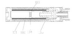
- FIG. 1The structure of the prior art atomizing assembly is shown in FIG. 1.
- the atomizing assemblyis used to atomize the smoke oil to form a smoke for the user to take.
- the specific arrangementis the inside of the atomizing sleeve 105.
- a fiberglass tube 102is disposed, and the exterior of the fiberglass tube 102 is surrounded by a reservoir cotton 101 for storing smoke oil.
- the fiberglass tube 102is internally provided with a glass fiber line 103, the end of the glass fiber line 103 passes through the fiberglass tube 102, and is inserted into the oil storage cotton 101, and the glass fiber line 103 is wound
- a columnar heating wire 104 for atomizing the smoke oilis provided. Passing the fiberglass tube 102 and the glass fiber line 103 such that the oil in the oil storage cotton 101 can be conducted to the heating wire 104 to atomize the heating wire 104 to form smoke. .
- the glass fiber line 103is disposed in a central portion of the atomizing assembly, and both ends of the oil storage cotton 101 for storing the oil smoke extend to both ends of the atomizing sleeve 105. That is, the glass fiber line 103 is located in the central portion of the oil-storage cotton 101, and the smoke oil is easily accumulated in the position of the oil-storage cotton 101 away from the central portion of the atomizing assembly due to gravity during smoking, thereby The smoke oil stored in the oil storage cotton 101 cannot be sufficiently atomized, thereby causing considerable waste of waste oil, and the problem of dry burning of the conductive wire 104 is easy, and the atomizing component cannot be grasped by the user of the prior art atomizing assembly.
- the amount of smoke oil remaining thereinmakes it impossible to determine the length of time that the atomizing assembly can be used, thereby causing inconvenience to the user, and if the atomizing component of the prior art hits or falls, it is extremely easy to be broken, thereby causing fog.
- the chemical componentis cracked, the smoke oil is easily leaked from the atomization sleeve 105; in addition, the existing atomization assembly is not easy to distinguish whether it has been used or not, thereby causing a health hazard to the user.
- the inventionprovides an atomization assembly and an electronic cigarette.
- An atomizing assemblyfor combining with a battery rod assembly to form an electronic cigarette, wherein
- the atomizing assemblyincludes a nozzle assembly, an oil cup assembly and an atomizing core assembly;
- the nozzle assemblyincludes a nozzle and a transparent atomizing sleeve, the atomizing sleeve is provided with the nozzle at one end and the atomizing core assembly at the other end;
- the oil cup assemblyincludes a transparent oil storage sleeve for storing smoke oil in the atomization sleeve, and a gap between an outer circumferential surface of the oil storage sleeve and an inner circumferential surface of the atomization sleeve forms a cylinder a smoke passage, the end of the oil storage sleeve facing the nozzle is a closed end, and an end surface of the oil storage sleeve facing the nozzle and the nozzle is formed with the smoke passage and a first condensed soot storage space in which the air outlet of the nozzle communicates; an end of the oil storage sleeve facing away from the nozzle is provided with an open end for adding smoke oil;
- One end of the atomizing core assemblyis inserted into an end of the nozzle assembly and the oil cup assembly adjacent to the battery rod assembly and is detachably connected to the nozzle assembly and the oil cup assembly
- the end of the atomizing core assembly facing away from the nozzleis detachably connected to the battery rod assembly, and an end of the atomizing core assembly remote from the nozzle is provided for electrically connecting with the battery rod assembly.
- An atomizing electrode assemblywherein the atomizing core assembly is provided with an atomizing chamber communicating with the smoke passage and an electric heating wire assembly for atomizing the tobacco oil in the atomizing chamber, the electric heating wire assembly and The atomizing electrode assembly is electrically connected.
- the oil storage sleeveis movably sleeved in the atomization sleeve to release the mist after the atomization core assembly is removed from the nozzle assembly together with the oil cup assembly
- the connection of the core assembly to the oil cup assemblyadds soot to the oil reservoir.
- a peripheral surface of the orifice of the air outlet facing the one end of the oil reservoiris convexly disposed on a side close to the atomizing core assembly for blocking the entry of the oil into the air outlet.
- an end surface of the oil storage sleeve facing the nozzleis a convex surface convex toward the nozzle so that if the condensed smoke oil is stored in the first condensed soot storage space, The smoky oil flows back along the convex surface into the smoke passage.
- a sidewall of the atomizing core assemblyis provided with a smoke exhausting hole communicating with the smoke passage and the atomizing chamber, between the sidewall of the atomizing core assembly and the atomizing sleeve Forming a second condensed soot storage space, the second condensed soot storage space and the smoke passage are respectively located on opposite sides of the exhaust hole, and the second condensed soot storage space and the smoke
- the passagesare in communication with each other such that the condensed soot in the smoke passage can flow into the second condensed soot storage space when the atomizing assembly is placed vertically.
- the atomizing core assemblyfurther includes a grease barrier cover embedded at the open end, the heating wire assembly is located between the atomizing electrode assembly and the grease barrier, the oil barrier cover
- the atomizing electrode assemblyis plugged and detachably connected to the oil cup assembly so that when the atomizing core assembly is clamped
- the oil cup assemblyis disassembled for adding smoke oil
- the oil separation coveris provided with an oil guiding hole communicating with an oil storage space of the oil storage sleeve
- the electric heating wire assemblyis provided with a material for adsorbing the oil guiding hole.
- the atomizing core assemblyfurther comprises an oil absorbing sleeve made of a fiber material, the outer peripheral surface of the oil absorbing sleeve is formed with a bonding layer, the oil guiding rope is erected on the oil absorbing sleeve, and the oil absorbing The inner cavity of the sleeve is formed with the atomization chamber, and after the oil guiding hole introduces the oil into the oil absorbing sleeve, the oil guiding rope adsorbs the oil from the oil absorbing sleeve to atomize the heating wire. .
- a side of the oil-shielding cover facing away from the nozzleis provided with a buffer plate made of an oil-absorbing material, and one end of the oil-absorbing sleeve abuts against a side of the buffer plate facing away from the oil-repellent cover side.
- the oil absorbing sleeveis provided with two guiding slots that are opposite to each other and extend to an end surface of the oil absorbing sleeve facing the one end of the oil absorbing cover, and two ends of the oil guiding rope are respectively inserted in the guiding groove on.
- the outer peripheral surface of the oil absorbing sleeveis formed by heating and melting.
- the atomizing core assemblyfurther includes an atomizing seat, the oil guiding rope is disposed on the atomizing seat, and the inner cavity of the atomizing seat is formed with the atomizing cavity, the oil guiding hole The oil is introduced into the oil guiding rope in the atomizing seat to atomize the heating wire.
- the outer peripheral surface of one end of the atomizing sleeveis sleeved with a first fastening ring made of a metal material
- the atomizing electrode assemblyincludes inner electrodes, insulating members and outer parts which are sequentially connected from the inside to the outside.
- An electrode, the two ends of the heating wireare electrically connected to the inner electrode and the outer electrode, respectively, the outer electrode is detachably connected to the first fastening ring and the battery rod assembly, and the oil barrier cover The one end of the outer electrode facing away from the battery rod assembly is connected and connected;
- the outer peripheral surface of the open end of the oil storage sleeveis sleeved with a second fastening ring made of a metal material, and the oil storage sleeve is tightly coupled with the second fastening ring, and the second fastening is
- the ringis detachably coupled to the atomizing core assembly.
- the inner wall of the atomization sleeveis provided with a groove
- the outer wall of the oil cup assemblyis provided with a convex bone that cooperates with the groove, and the atomization sleeve and the oil cup assembly pass the convex The joint of the bone and the groove is detachably connected.
- the structure of the detachable connection between the oil cup assembly and the atomizing core assemblyis a threaded connection structure; or/and
- the atomizing electrode assemblyis detachably coupled to the nozzle assembly, and the detachably connected structure is a threaded connection structure.
- the oil-repellent coveris provided with a plurality of oil guiding holes surrounded by an annular shape or an arc shape, and the oil guiding holes are equally spaced between each other.
- the oil guiding holehas a pore diameter of less than 1.5 mm.
- the nozzleis integrally or detachably connected to the atomization sleeve, wherein the nozzle is a transparent material member.
- the present inventionalso discloses an electronic cigarette comprising an interconnected battery rod assembly and an atomizing assembly, such as the atomizing assembly of any of the above.
- the usercan check the remaining amount of smoke oil at any time through the transparent oil storage sleeve, so that the user can estimate the atomization assembly can also be used according to the remaining amount of smoke oil.
- the length of time, and the cleaning of the oil storage sleeve according to the amount of remaining oil and the addition of new oilthere will be no burning of the atomizing component due to insufficient residual oil, and the condensed smoke will be more sticky when smoking.
- the usercan observe whether the atomizing component is used by observing whether the atomizing component is used by observing the smoke passage of the atomizing component through the transparent oil storage sleeve, so that it is convenient to distinguish whether the atomizing component is sanitary. Effectively protects the health of users using e-cigarettes;
- the gap between the outer circumferential surface of the oil storage sleeve and the inner circumferential surface of the atomization sleeveforms a cylindrical smoke passage, the area of the smoke passage is large, so that the contact area between the smoke and the inner wall of the smoke passage is large,
- the smoke atomized by the heating wire assemblycan be cooled to a suitable temperature when flowing through a large-area smoke passage, thereby improving the comfort of the user during the smoke suction, preventing the user from sucking the high temperature smoke and scalding
- the atomizing sleevewill protect the oil storage sleeve, so that the oil storage sleeve will not be broken, thereby effectively avoiding oil leakage due to dropping or collision, effectively extending the fog.
- the storagemay be stored without atomization or atomization.
- the smoky oil, or the condensed smoky oilcan effectively prevent the smoky oil in the smoke passage from entering the user's mouth, and preferably avoids the user from smoking the smoky oil;
- Figure 1is a cross-sectional view of a prior art atomizing assembly
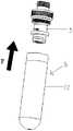
- FIG. 2is a cross-sectional view of an atomizing assembly according to an embodiment of the present invention.
- FIG. 3is another cross-sectional view of the atomizing assembly provided by the embodiment of the present invention.
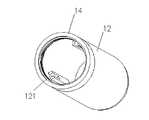
- FIG. 4ais a schematic structural view of a nozzle assembly according to an embodiment of the present invention.
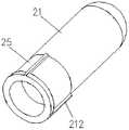
- FIG. 4bis a schematic structural view of an oil cup assembly according to an embodiment of the present invention.
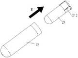
- 4c to 4dare schematic views showing the installation of the nozzle assembly, the oil cup assembly and the atomizing core assembly;
- FIG. 5is a cross-sectional structural view of the atomization sleeve and the nozzle according to an embodiment of the present invention
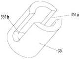
- FIG. 6is a schematic structural view of an oil absorbing sleeve provided by an embodiment of the present invention.
- FIG. 7is an exploded view of an atomizing assembly provided by an embodiment of the present invention.
- An embodiment of the present inventionprovides an atomizing assembly, and an electronic cigarette is also provided. Please refer to FIG. 1 to FIG. 7 , which will be described in detail below with specific embodiments.
- Embodiments of the present inventionprovide an atomization assembly for combining with a battery rod assembly to form an electronic cigarette, and an atomization assembly for atomizing the smoke oil to form a smoke.
- FIG. 2 and FIG. 3are both cross-sectional views of the atomizing assembly provided by the embodiment of the present invention, and FIG. 2 and FIG. 3 are the same fog.
- the atomizing assemblycan include a nozzle assembly 1, an oil cup assembly 2, and an atomizing core assembly 3.
- the nozzle assembly 1includes a suction nozzle 11 and a transparent atomizing sleeve 12, and the atomizing sleeve 12 is provided with the suction nozzle 11 at one end and the atomizing core assembly 3 at the other end.
- the degree of transparency of the atomizing sleeve 12 and the specific materialare not limited. As long as the user can view the remaining amount of smoke oil of the atomizing assembly through the atomizing sleeve 12, the transparent oil storage sleeve can be viewed at any time. The amount of remaining soot oil, so that the user can estimate the length of time that the atomizing assembly can be used according to the remaining amount of the soot oil, and clean the oil storage sleeve or add new oil according to the amount of remaining oil, which does not appear.
- the atomizing componentis burned out due to insufficient remaining amount of smoke oil, and the condensed smoke oil is more likely to adhere to the smoke passage when smoking, so the user can observe the smoke passage of the atomizing assembly through the transparent oil storage sleeve. Whether there is condensed liquid smoke to infer whether the atomizing component has been used, thereby making it easier to distinguish whether the atomizing component is hygienic, and effectively protecting the health of the user using the electronic cigarette.
- One end of the atomizing sleeve 12is provided with a suction nozzle 11 so that the user can suck the mist atomized by the atomizing core assembly 3 through the suction nozzle 11.
- the specific setting manner of the suction nozzle 11 and the atomizing sleeve 12is not used in this embodiment. Qualified, the two can be integrally formed or detachable. This will be described in detail in the following embodiments, and details are not described herein again.
- the oil cup assembly 2includes a transparent oil storage jacket 21 for storing the oil in the atomization sleeve 12.
- the oil storage jacket 21is internally provided with an oil storage space for storing the oil, which can be stored inside the oil storage jacket 21.
- the amount of the soot oilis used to effectively increase the length of use of the atomizing assembly.
- the liquid smoke stored in the oil storage jacket 21is taken as an example for description.
- a gap between the outer circumferential surface of the oil storage jacket 21 and the inner circumferential surface of the atomizing sleeve 12forms a cylindrical smoke passage 22.
- a smoke passage 22 communicating with the suction nozzle 11is formed between the oil storage jacket 21 and the atomization sleeve 12, so that the mist atomized by the atomization core assembly 3 passes through the oil storage jacket 21.
- the smoke passage 22 between the atomizing sleeve 12 and the mist passage 22flows to the air outlet 111 of the suction nozzle 11 to allow the user to draw through the air outlet 111.
- Smoking fogin which the specific flow of smoke is shown in the direction of the arrow shown in Figure 3.
- the advantage of the arrangement of the smoke passages 22 shown in this embodimentis that the area of the smoke passages 22 is greatly improved relative to the prior art, so that the contact area between the smoke and the inner wall of the smoke passage 22 is large.
- the smoke atomized by the heating wire assemblycan be cooled to a suitable temperature when flowing through the large-area smoke passage 22, thereby improving the comfort of the user during the smoke suction, and preventing the user from sucking the high temperature smoke.
- the atomizing sleeve 12functions to protect the oil storage sleeve 21, so that the oil storage sleeve 21 does not break, thereby effectively preventing oil leakage due to dropping or collision, and effectively The extension of the life of the atomizing component and the cost of replacing the atomizing component by the user.
- the cross section of the smoke passage 22 shown in this embodimenthas an annular structure, and the smoke passage 22 having a ring-shaped cross section has an advantage in that the external temperature is not easily transmitted to the oil in the oil storage casing 21. Therefore, it is better to avoid the problem that the smoke oil is easily deteriorated when the external environment temperature is high during storage or transportation, and the smoke oil leaks when it is expanded at a high temperature. It can be understood that, in the transportation or storage process, in order to prevent the external temperature from affecting the oil in the oil storage jacket 21, the air outlet 111 can be sealed by a sealing sleeve.
- An end of the oil storage sleeve 21 facing away from the suction nozzle 11is provided with an open end for adding the smoke oil, and one end of the oil storage sleeve 21 facing the suction nozzle 11 is a closed end, and an end surface of the oil storage sleeve 21 facing the suction nozzle 11 and the suction nozzle 11 A first condensed soot storage space 23 communicating with the smoke passage 22 and the air outlet 111 of the suction nozzle 11 is formed therebetween.
- the advantage of providing the first condensed smoky oil storage space 23 in the embodiment of the present inventionis that in the first condensed smoky oil storage space 23, the smoky oil which is not atomized or atomized sufficiently, or the condensed smoky oil can be stored. It can effectively prevent the smoke oil in the smoke passage from entering the user's mouth, and better avoid the user from absorbing the condensed smoke oil.
- the other end of the atomizing sleeve 12is provided with an atomizing core assembly 3, as shown in FIG. 2 or 3.
- An end of the atomizing core assembly 3 remote from the nozzle 11is provided with an atomizing electrode for electrically connecting with the battery rod assembly.
- the assembly 31, the atomizing core assembly 3is provided with an atomizing chamber 32 communicating with the smoke passage 22 and an electric heating wire assembly 33 for atomizing the tobacco oil in the atomizing chamber 32, the heating wire assembly 33 and the atomizing electrode assembly 31 electrical connection.
- the atomizing core assembly 3is inserted into the atomizing sleeve 12, which can facilitate assembly and effectively improve the efficiency of assembling the atomizing assembly.
- the heating wire assembly 33can be fixed on the atomizing seat, and the inner cavity of the atomizing seat is formed with an atomizing cavity 32, and the heating wire assembly 33 is stably received in the atomizing cavity 32, so that the heating wire assembly 33 can be stabilized. Atomize the smoke oil to create a uniform smoke, which enhances the user's suction taste.
- the heating wire assembly 33can be fixed on the oil suction sleeve, and the inner cavity of the oil suction sleeve is formed with an atomization chamber 32, and the heating wire assembly 33 is stably received in the atomization chamber 32. It should be noted that the specific implementation of the atomization base and the oil suction sleeve will be described in detail in the following embodiments, and details are not described herein again.
- One end of the atomizing core assembly 3is inserted into one end of the nozzle assembly 1 and the oil cup assembly 2 adjacent to the battery rod assembly and is detachably connected to the nozzle assembly 1 and the oil cup assembly 2, and the atomizing core assembly 3 is One end facing away from the suction nozzle 11 is detachably connected to the battery rod assembly.
- the detachable connection manner of the atomizing core assembly 3 and the nozzle assembly 1 and the oil cup assembly 2is not specifically limited in this embodiment.
- the detachable connection manner of the atomizing core assembly 3 and the battery rod assemblyis not specifically limited.
- the nozzle assembly 1, the oil cup assembly 2 and the atomizing core assembly 3are detachably connected to each other, and the detachable connection between them makes it convenient for the user to add the oil and according to the atomization.
- the amount of condensed soot in the sleeveis replaced or the oil reservoir is cleaned, thereby ensuring the health of the user using the atomizing assembly.
- the methodmay mainly include: the oil storage sleeve 21 is movably sleeved in the atomization sleeve 12, then the atomization core assembly 3 is After the oil cup assembly 2 is detached from the nozzle assembly 1, the connection of the atomizing core assembly 3 and the oil cup assembly 2 is released, and the oil can be added to the oil storage jacket 21.
- the transparent atomizing sleeve and the oil storage sleeveprovided by the embodiments of the present invention are convenient for the user to check the amount of remaining oil, thereby protecting the atomizing component and ensuring the health of the user;
- the tubular smoke passageincreases the smoke.
- the contact area, effective cooling of the smokeavoids problems such as burns to the user;
- the first condensed soot storage spacecan further ensure that the user does not smoke the condensed smoke oil;
- the atomizing core assemblyis detachably connected to the nozzle assembly and the oil cup assembly It is easy to add or replace smoke oil and clean the oil storage sleeve to further ensure the health of the user.
- FIG. 4 ais the structure of the nozzle assembly.
- FIG. 4bis a schematic view of the structure of the oil cup assembly
- FIG. 4cis a schematic view of the installation of the nozzle assembly and the oil cup assembly
- FIG. 4dis the atomizing core assembly and the nozzle assembly and the oil cup assembly that have been installed together in FIG. 4c.
- FIG. 5is a schematic cross-sectional structural view of the suction nozzle and the atomization sleeve
- FIG. 6is a schematic structural view of the oil suction sleeve
- FIG. 7is an exploded view of the atomization assembly.
- the oil storage sleeve 21can be actively disposed in the atomization sleeve 12, and then the atomization core assembly 3 is After the oil cup assembly 2 is detached from the nozzle assembly 1, the connection of the atomizing core assembly 3 and the oil cup assembly 2 is released, and the oil can be added to the oil storage jacket 21.
- oil storage sleeve 21being slidably disposed in the atomization sleeve 12 may include at least the following three embodiments:
- the inner wall of the atomization sleeve 12is provided with a groove 121.
- the outer wall of the oil cup assembly 2is provided with a convex bone 212, wherein the convex bone 212 and the groove 121 are provided. Can match each other.
- the atomizing sleeve 12can first be sleeved with the oil storage sleeve 21 in the direction of the arrow E, that is, the detachable connection is made by the cooperation of the convex bone 212 and the groove 121, so that the oil storage sleeve 21 is movable.
- the ground coveris set in the atomization sleeve 12, and the installation diagram thereof is shown in Fig. 4c. Then, the mounting completion member 5 formed by combining the atomizing sleeve 12 and the oil storage sleeve 21 is assembled with the atomizing core assembly 3 in the direction of the arrow F in the figure to complete the assembly of the atomizing assembly, wherein the atomizing sleeve 12 and the oil storage portion are completed.
- the mounting member 5 formed by the combination of the sleeves 21is detachably connected to the atomizing core assembly, and the mounting diagram thereof can be referred to FIG. 4d.
- the mounting completion 5 and the detachable connection structure of the atomizing core assembly formed by the combination of the atomizing sleeve 12 and the oil storage sleeve 21are not limited, and may be, for example, a screw connection or a snap connection.
- the detachable connection between the mounting member 5 and the atomizing core assemblycan be realized by the detachable connection of the atomizing electrode assembly 31 and the oil storage sleeve 21, and the detachable connecting structure can be a threaded connection, etc.
- the inventionis not limited.
- a sealing sleeve or a sealing ringmay be provided at the connection between the atomizing electrode assembly 31 and the oil storage sleeve 21, thereby increasing the sealing.
- the reliabilityguarantees the reliability of the installation.
- the structure of the detachable connection between the atomization sleeve 12 and the oil storage sleeve 21is a threaded connection structure, and the detachable connection structure between the installation completion member 5 and the atomization core assembly may also be through the atomization electrode.
- the assembly 31is detachably connected to the oil storage sleeve 21, and the detachable connection structure may be a threaded connection or the like, which is not limited in the present invention.
- the oil storage sleeve 21is matched with the atomization sleeve 12 and sleeved in the atomization sleeve 12, and the oil storage sleeve 21 and the atomization core assembly 3 are tightly matched.
- the detachable connectionis made by means of a thread or a snap, and the atomizing sleeve 12 is detachably connected to the atomizing core assembly 3 by means of a tension fit, a thread or a snap.
- connection manner of the atomizing sleeve 12 and the oil storage sleeve 21 in this embodimentis merely described as an example and is not limited.
- the nozzle assembly 1includes a suction nozzle 11 and a transparent atomization sleeve 12.
- the nozzle 11is made of a transparent material, so that the user can check whether the smoke oil is accumulated at the nozzle 11 at any time.
- a detachable connecting structureis formed between the suction nozzle 11 and the atomizing sleeve 12.
- the detachable connecting structureis not limited in this embodiment, for example, the suction nozzle 11 and the atomizing sleeve 12
- the structure of the detachable connectionis a screw connection structure or a snap connection structure.
- the screw connection between the suction nozzle 11 and the atomization sleeve 12is exemplified, for example, the inner circumferential surface of the suction nozzle 11 can be used.
- An internal thread 601is provided, and an external thread 602 matching the internal thread 601 is disposed at a position corresponding to the internal thread 601 of the atomizing sleeve 12, so that the suction nozzle 11 and the atomizing sleeve 12 pass through the internal thread 601 and the external thread 602. Screw-on and detachable connection.
- the detachable connection between the suction nozzle 11 and the atomizing sleeve 12has the advantages that the user can change the suction nozzle 11 at any time, so that the user can clean or periodically replace the suction nozzle 11 at any time, thereby effectively ensuring that the user uses the suction nozzle 11 to perform the cleaning. Hygiene of the smoke extraction process.
- the suction nozzle 11 and the atomizing sleeve 12are integrally formed, thereby effectively ensuring the stability of the connection between the atomizing sleeve 12 and the suction nozzle 11.
- the end surface of the oil-storing sleeve 21 facing the one end of the suction nozzle 11is a circular arc-shaped convex surface which is convex toward the suction nozzle 11, and the end face of the oil-storing sleeve 21 facing the suction nozzle 11
- the smoky oilflows back along the end surface of the arc-shaped oil storage casing 21 to the atomization chamber 32 to make the electric heating wire assembly. 33 can atomize the smoke oil that is re-flowed back into the atomization chamber 32, further effectively preventing the user from absorbing the condensed smoke oil.
- a peripheral edge of the air outlet 111 facing the one end of the oil storage sleeve 21is convexly disposed on a side close to the atomizing core assembly 3 for blocking the smoke oil from entering the air outlet 111. Taiwan 13, Thereby further preventing the user from pumping the smoke oil.
- the outer end surface of the suction nozzle 11is a spherical surface, and the spherical suction nozzle 11 can be easily deformed when being subjected to the clamping force of the oral cavity, and more closely matches the mouth shape of the user, thereby allowing the user to smoke the smoke. It is more comfortable and more convenient for the user to clean the nozzle 11.
- the side wall of the atomizing core assembly 3is provided with a smoke exhausting hole 321 communicating with the smoke passage 22 and the atomizing chamber 32.
- the side wall of the atomizing core assembly 3 and the atomizing sleeve 12are formed with a second condensed soot storage space 24, the second condensed soot storage space 24 and the smoke passage 22 are respectively located on opposite sides of the exhaust hole 321 , and the second condensed soot storage space 24 and the smoke passage The 22 are in communication with each other such that the condensed soot in the smoke passage 22 can flow into the second condensed soot storage space 24 when the atomizing assembly is placed vertically.
- the second condensed smoky oil storage space 24can further store the smoky oil which is not completely atomized or atomized or is condensed, and can effectively prevent the smoky oil in the smoke passage from entering the user's mouth, and better avoids the user absorbing the condensation.
- Smoke oilSince the second condensed soot storage space 24 and the smoke passage 22 are respectively located on opposite sides of the exhaust hole 321 , the smoke oil can be prevented from flowing into the battery rod assembly through the exhaust hole 321 , thereby avoiding the smoke.
- the problem of oil flowing into the battery rod assemblycauses a short circuit.
- the smoke atomized by the heating wire assembly 33flows into the smoke passage 22 through the exhaust hole 321 in the atomizing chamber 32 until it flows to the suction nozzle 11.
- the specific flow direction of the smokeis shown by the arrow in FIG. direction.
- the exhaust holes 321are two, and the two exhaust holes 321 are opposite in position. It should be noted that the specific number is not limited in the present invention, as long as it is greater than or equal to 1.
- the atomizing core assembly 3further includes an oil-repellent cover 34 embedded at the open end, the electric heating wire assembly 33 is located between the atomizing electrode assembly 31 and the oil-repellent cover 34, and the oil-repellent cover 34 and the mist
- the electrode assembly 31is detachably connected and detachably connected to the oil cup assembly 2, so that the oil cup assembly 2 can be detached for adding the smoke oil when the atomizing core assembly 3 is clamped, thereby facilitating the use of the user and improving the user.
- the oil-discharging cover 34is provided with an oil guiding hole 341 communicating with the oil storage space of the oil storage jacket 21, and the heating wire assembly 33 is provided with an oil guiding rope for adsorbing the oil smoke derived from the oil guiding hole 341 and wound around the oil guiding rope.
- the electric heating wireis electrically connected to the atomizing electrode assembly 31.
- the oil guiding ropecan also be replaced with an oil guiding sleeve, and the electric heating wire is sleeved in the oil guiding sleeve; or the oil guiding rope is replaced with an oil guiding plate, the electric heating wire It is provided in a disk shape and fitted to one side of the oil guide plate. Therefore, the structure of the heating wire assembly 33 is not particularly limited as long as the smoke oil can be atomized.
- the oil in the oil storage sleeve 21can be conducted to the oil guiding rope through the oil guiding hole 341 on the oil separating cover 34, so that the oil oil on the oil guiding rope is enough to supply the electric heating wire wound around the oil guiding rope. Therefore, the concentration of the atomized smoke of the heating wire is effectively ensured, and the phenomenon of scorching due to the shortage of the smoke oil on the oil guiding rope is prevented, and due to the setting of the oil separating cover 34, the excessive transportation of the oil is effectively avoided. Give the heating wire to avoid leakage of smoke oil.
- the oil-removal cover 34is provided with a plurality of oil-conducting holes 341 which are formed in an annular shape or an arc shape, and the respective oil-conducting holes 341 are disposed at equal intervals.
- the specific number of the oil guiding holes 341is not limited, as long as it is equal to or greater than two.
- the oil guide hole 341has a diameter of less than 1.5 mm. More preferably, it is 1 mm, so that the tobacco oil is conveyed reasonably to avoid dry burning or excessive transportation of the oil.
- the atomizing core assembly 3further includes an atomizing seat 37.
- the oil guiding ropeis disposed on the atomizing seat 37.
- the inner cavity of the atomizing seat 37is formed with an atomizing chamber 32, and the oil guiding hole 341 introduces the oil and smoke.
- the oil guiding ropeis used to atomize the heating wire.
- the specific arrangement of the atomizing seat 37is not limited in this embodiment, as long as the atomizing seat 37 can firmly set the heating wire assembly 33.
- the side wall of the atomizing seat 37is provided with a retaining groove in communication with the atomizing chamber 32, so that the end of the heating wire assembly 33 away from the suction nozzle 11 is fixed by the holding groove to the atomizing seat 37. It is placed in the atomization chamber 32.
- the present embodimentdiffers from FIG. 3 in that the atomizing core assembly 3 replaces the atomizing seat 37 with an oil suction jacket 35. That is, the atomizing core assembly 3 further includes an oil absorbing sleeve 35 made of a fiber material. The outer peripheral surface of the oil absorbing sleeve 35 is formed with an adhesive layer. The oil guiding rope is disposed on the oil absorbing sleeve 35, and the inner cavity of the oil sucking sleeve 35 is formed with fog. After the oil passage hole 341 introduces the smoke oil into the oil suction jacket 35, the oil guide rope adsorbs the smoke oil from the oil suction jacket 35 to the electric heating wire for atomization.
- a side of the oil-shielding cover 34 facing away from the suction nozzle 11is provided with a buffer plate 36 made of an oil absorbing material, and one end of the oil suction sleeve 35 abuts against the oil-repellent cover of the buffer plate 36.
- a buffer plate 36made of an oil absorbing material
- the oil guiding hole 341 on the oil separating cover 34can transfer the oil in the oil storage casing 21 to the buffer plate 36, and the buffering plate 36 can transfer the adsorbed oil to the oil suction jacket 35 to ensure that the oil suction jacket 35 can
- the smoky oilis transferred to the oil guiding rope erected thereon, and the smoky oil is atomized by the electric heating wire, so that the smoky oil which is led away from the oil guiding hole 341 of the oil absorbing sleeve 35 can also pass through the buffering plate 36. Conducted to the oil absorption In the sleeve 35, it is avoided that the problem that the end face of the oil suction jacket 35 may not cover the oil guiding hole 341 is easily caused when only the oil storage jacket 21 is provided.
- the oil suction sleeve 35is provided with two guiding slots 351a, 351b opposite to each other and extending to the end surface of the oil suction sleeve 35 facing the oil-removal cover 34, and the two ends of the oil guiding rope 331 are respectively inserted.
- the guide groove 351is provided, and the outer peripheral surface of the oil suction jacket 35 is formed by heating and melting to form an adhesive layer, so that the oil suction jacket 35 can securely fix the heating wire assembly 33. By heating and melting to form the adhesive layer, it is possible to easily cause harmful atomization when bonding by glue, and the user's health is well protected.
- the atomizing component 3releases heat during the process of atomizing the smoke oil, and the released heat is extremely easy to cause the atomizing sleeve 12 to be deformed by thermal expansion, thereby causing the atomizing sleeve 12 and the atomizing core assembly 3 to be deformed.
- the loosening of the atomizing componentaffects the service life of the atomizing component.
- the outer peripheral surface of the atomizing sleeve 12 of the embodimentis provided with a first fastening ring 14 made of a metal material, specifically The first fastening ring 14 for restricting the radial expansion of the atomizing sleeve 12 is sleeved at a position where the atomizing sleeve 12 is connected to the atomizing core assembly 3.
- FIG. 7is an exploded view of the atomizing assembly, in which the gasket and the sealing ring are not shown.
- the outer peripheral surface of one end of the atomizing sleeve 12is sleeved with a first fastening ring 14 made of a metal material, and the atomizing electrode assembly 31 includes an inner electrode 311, an insulating member 312 and an outer electrode 313 which are sequentially connected from the inside to the outside.
- the two ends of the heating wireare electrically connected to the inner electrode 311 and the outer electrode 313, respectively, and the outer electrode 313 is detachably connected to the first fastening ring 14 and the battery rod assembly, and the oil-shielding cover 34 and the outer electrode 313 are away from the battery rod assembly.
- One endis connected and connected;
- the first fastening ring 14is made of a metal material, which can increase the connection strength between the atomization sleeve 12 and the atomization core assembly 3.
- the first fastening ring 14can realize the atomization core assembly 3.
- the detachable connection with the nozzle assembly 1facilitates the user to add the smoke oil and replace or clean the oil storage sleeve according to the amount of the condensed smoke oil in the atomization sleeve, thereby ensuring the health of the user using the atomization assembly process.
- the outer peripheral surface of the open end of the oil storage sleeve 21is sleeved with a second fastening ring 25 made of a metal material, and the oil storage sleeve 21 is fixedly connected with the second fastening ring 25, and the second fastening ring 25 and the mist
- the core assembly 3is detachably connected.
- the second fastening ring 25 in the embodiment of the present inventioncan realize the detachable connection between the oil cup assembly 2 and the atomizing core assembly 3, so that the user can add the oil and replace or clean the oil according to the amount of the condensed oil in the atomizing sleeve.
- the sleevethus protects the health of the user using the atomizing assembly process.
- the second fastening ring 25is provided with the convex bone 212.
- the convex bone 212may also be disposed on the oil storage sleeve 21, which is not specifically limited herein.
- the atomizing electrode assembly 31includes an inner electrode 311, an insulating member 312, and an outer electrode 313 which are sequentially connected from the inside to the outside.
- the detachable connection between the atomizing electrode assembly and the oil storage sleevecan be achieved by a detachable connection between the outer electrode 313 and the oil storage sleeve 21, and the detachable connection structure can be a threaded connection structure.
- the two ends of the heating wireare electrically connected to the inner electrode 311 and the outer electrode 313, respectively, and the oil-shielding cover 34 is connected to the end of the outer electrode 313 facing away from the battery rod assembly, so that the battery rod assembly can supply power to the heating wire assembly 33, so that The heating wire assembly 33 atomizes the smoke oil to generate smoke.
- the transparent atomizing sleeve and the oil storage sleeveprovided by the embodiments of the present invention are convenient for the user to check the amount of remaining oil, thereby protecting the atomizing component and ensuring the health of the user;
- the tubular smoke passageincreases the smoke.
- the contact area, effective cooling of the smokeavoids problems such as scalding the user;
- the first condensed soot storage spacecan further ensure that the user does not smoke the condensed smoke oil;
- the atomizing core assemblyis detachably connected with the nozzle assembly and the oil cup assembly, It is easy to add or replace smoke oil and clean the oil storage sleeve to further ensure the health of the user.
- Embodiments of the present inventionprovide an electronic cigarette including a detachably connected atomizing assembly and a battery rod assembly, and the battery rod assembly is configured to supply power to the atomizing assembly to atomize the atomizing assembly to form a smoke oil to form The smoke that can be used by the user, wherein the battery rod assembly is not described in the prior art.
- the battery rod assemblyis not described in the prior art.
Landscapes
- Disinfection, Sterilisation Or Deodorisation Of Air (AREA)
- Electrostatic Spraying Apparatus (AREA)
Abstract
Description
Translated fromChinese本发明涉及电子烟领域,尤其涉及一种雾化组件及电子烟。The present invention relates to the field of electronic cigarettes, and in particular to an atomizing assembly and an electronic cigarette.
现有技术的雾化组件的结构请参见图1所示,由图1可知,该雾化组件用以雾化烟油以形成可供用户吸食的烟雾,具体的设置方式为雾化套105内部设置有玻纤管102,所述玻纤管102外部围绕包覆设置有用于存储烟油的储油棉101。所述玻纤管102内部设置有玻纤线103,所述玻纤线103的端部穿过所述玻纤管102,并插入所述储油棉101,且所述玻纤线103上缠绕设置有用于雾化烟油的呈柱状的电热丝104。通过所述玻纤管102和所述玻纤线103以使得所述储油棉101内的烟油可传导到所述电热丝104上,以使所述电热丝104雾化烟油以形成烟雾。The structure of the prior art atomizing assembly is shown in FIG. 1. As can be seen from FIG. 1, the atomizing assembly is used to atomize the smoke oil to form a smoke for the user to take. The specific arrangement is the inside of the atomizing
可见,现有技术中将所述玻纤线103设置在所述雾化组件的中部区域,而用于存储烟油的储油棉101的两端延伸至所述雾化套105的两端,即所述玻纤线103位于所述储油油棉101的中部区域,由于吸烟时在重力的作用下烟油容易积存在储油棉101远离所述雾化组件的中部区域的位置,从而使得所述储油棉101所存储的烟油不能充分的雾化,进而造成相当的烟油浪费,而且容易误导电热丝104干烧的问题,而且采用现有技术雾化组件用户无法掌握雾化组件内剩余的烟油量,从而无法确定该雾化组件还能够使用的时长,从而为用户带来了不便,而且现有技术中的雾化组件若撞击或跌落,则极容易破裂,进而导致雾化组件有裂痕时烟油容易从所述雾化套105泄露出来;此外,现有的雾化组件不易于辨别是否被使用过,因而给用户造成卫生隐患。It can be seen that, in the prior art, the
发明内容Summary of the invention
本发明提供了一种雾化组件及电子烟。The invention provides an atomization assembly and an electronic cigarette.
一种雾化组件,用于与电池杆组件组合形成电子烟,其中,An atomizing assembly for combining with a battery rod assembly to form an electronic cigarette, wherein
所述雾化组件包括吸嘴组件、油杯组件和雾化芯组件;The atomizing assembly includes a nozzle assembly, an oil cup assembly and an atomizing core assembly;
所述吸嘴组件包括吸嘴和透明的雾化套,所述雾化套的一端设置有所述吸嘴,另一端插设有所述雾化芯组件;The nozzle assembly includes a nozzle and a transparent atomizing sleeve, the atomizing sleeve is provided with the nozzle at one end and the atomizing core assembly at the other end;
所述油杯组件包括位于所述雾化套内的用于储备烟油的透明的储油套,所述储油套的外周面与所述雾化套的内周面之间的间隙形成筒状的烟雾通道,所述储油套的面向所述吸嘴的一端为封闭端,所述储油套的面向所述吸嘴的端面与所述吸嘴之间形成有与所述烟雾通道及所述吸嘴的出气孔相连通的第一冷凝烟油存储空间,所述储油套背离所述吸嘴的一端设置有用于添加烟油的开口端;The oil cup assembly includes a transparent oil storage sleeve for storing smoke oil in the atomization sleeve, and a gap between an outer circumferential surface of the oil storage sleeve and an inner circumferential surface of the atomization sleeve forms a cylinder a smoke passage, the end of the oil storage sleeve facing the nozzle is a closed end, and an end surface of the oil storage sleeve facing the nozzle and the nozzle is formed with the smoke passage and a first condensed soot storage space in which the air outlet of the nozzle communicates; an end of the oil storage sleeve facing away from the nozzle is provided with an open end for adding smoke oil;
所述雾化芯组件的一端插设在所述吸嘴组件及所述油杯组件的与所述电池杆组件相邻的一端内并与所述吸嘴组件及所述油杯组件可拆卸连接,所述雾化芯组件的背离所述吸嘴一端与所述电池杆组件可拆卸连接,所述雾化芯组件的远离所述吸嘴的一端设置有用于与所述电池杆组件电连接的雾化电极组件,所述雾化芯组件内设置有与所述烟雾通道相连通的雾化腔及位于所述雾化腔内用于雾化烟油的电热丝组件,所述电热丝组件与所述雾化电极组件电连接。One end of the atomizing core assembly is inserted into an end of the nozzle assembly and the oil cup assembly adjacent to the battery rod assembly and is detachably connected to the nozzle assembly and the oil cup assembly The end of the atomizing core assembly facing away from the nozzle is detachably connected to the battery rod assembly, and an end of the atomizing core assembly remote from the nozzle is provided for electrically connecting with the battery rod assembly. An atomizing electrode assembly, wherein the atomizing core assembly is provided with an atomizing chamber communicating with the smoke passage and an electric heating wire assembly for atomizing the tobacco oil in the atomizing chamber, the electric heating wire assembly and The atomizing electrode assembly is electrically connected.
优选地,所述储油套活动地套设于所述雾化套内,以使将所述雾化芯组件连同所述油杯组件一起从所述吸嘴组件拆出后,解除所述雾化芯组件与所述油杯组件的连接便可向所述储油套内添加烟油。Preferably, the oil storage sleeve is movably sleeved in the atomization sleeve to release the mist after the atomization core assembly is removed from the nozzle assembly together with the oil cup assembly The connection of the core assembly to the oil cup assembly adds soot to the oil reservoir.
优选地,所述出气孔的面向所述储油套一端的孔口周缘朝靠近所述雾化芯组件的一侧凸设有用于阻隔烟油进入出气孔的筒形凸台。Preferably, a peripheral surface of the orifice of the air outlet facing the one end of the oil reservoir is convexly disposed on a side close to the atomizing core assembly for blocking the entry of the oil into the air outlet.
优选地,所述储油套的面向所述吸嘴的端面为朝所述吸嘴方向凸起的凸面,以使若所述第一冷凝烟油存储空间内存储有冷凝的烟油时,则烟油沿所述凸面回流至所述烟雾通道中。Preferably, an end surface of the oil storage sleeve facing the nozzle is a convex surface convex toward the nozzle so that if the condensed smoke oil is stored in the first condensed soot storage space, The smoky oil flows back along the convex surface into the smoke passage.
优选地,所述雾化芯组件的侧壁处设置有与所述烟雾通道及所述雾化腔相连通的排烟孔,所述雾化芯组件的侧壁与所述雾化套之间形成有第二冷凝烟油存储空间,所述第二冷凝烟油存储空间与所述烟雾通道分别位于所述排烟孔的相对两侧,且所述第二冷凝烟油存储空间与所述烟雾通道相互连通,以使雾化组件竖直放置时所述烟雾通道中冷凝的烟油能够流入所述第二冷凝烟油存储空间内。Preferably, a sidewall of the atomizing core assembly is provided with a smoke exhausting hole communicating with the smoke passage and the atomizing chamber, between the sidewall of the atomizing core assembly and the atomizing sleeve Forming a second condensed soot storage space, the second condensed soot storage space and the smoke passage are respectively located on opposite sides of the exhaust hole, and the second condensed soot storage space and the smoke The passages are in communication with each other such that the condensed soot in the smoke passage can flow into the second condensed soot storage space when the atomizing assembly is placed vertically.
优选地,所述雾化芯组件还包括嵌设在所述开口端处的隔油盖,所述电热丝组件位于所述雾化电极组件及隔油盖之间,所述隔油盖与所述雾化电极组件插接相连并与所述油杯组件可拆卸连接,以使在夹住所述雾化芯组件时能够将所述油杯组件拆卸下来进行添加烟油,所述隔油盖设置有与所述储油套的储油空间相连通的导油孔,所述电热丝组件设置有用于吸附导油孔导出的烟油的导油绳及缠绕在所述导油绳上的电热丝,所述电热丝与所述雾化电极组件电连接。Preferably, the atomizing core assembly further includes a grease barrier cover embedded at the open end, the heating wire assembly is located between the atomizing electrode assembly and the grease barrier, the oil barrier cover The atomizing electrode assembly is plugged and detachably connected to the oil cup assembly so that when the atomizing core assembly is clampedThe oil cup assembly is disassembled for adding smoke oil, and the oil separation cover is provided with an oil guiding hole communicating with an oil storage space of the oil storage sleeve, and the electric heating wire assembly is provided with a material for adsorbing the oil guiding hole. An oil guiding rope of the oil and a heating wire wound around the oil guiding wire, the heating wire being electrically connected to the atomizing electrode assembly.
优选地,所述雾化芯组件还包括由纤维材料制成的吸油套,所述吸油套的外周面形成有一层粘接层,所述导油绳架设在所述吸油套上,所述吸油套的内腔形成有所述雾化腔,所述导油孔将烟油导入所述吸油套中后,所述导油绳从所述吸油套中吸附烟油给所述电热丝进行雾化。Preferably, the atomizing core assembly further comprises an oil absorbing sleeve made of a fiber material, the outer peripheral surface of the oil absorbing sleeve is formed with a bonding layer, the oil guiding rope is erected on the oil absorbing sleeve, and the oil absorbing The inner cavity of the sleeve is formed with the atomization chamber, and after the oil guiding hole introduces the oil into the oil absorbing sleeve, the oil guiding rope adsorbs the oil from the oil absorbing sleeve to atomize the heating wire. .
优选地,所述隔油盖背离所述吸嘴的一侧盖设有由吸油材料制成的缓冲板,所述吸油套的一端抵持在所述缓冲板的背离所述隔油盖的一侧。Preferably, a side of the oil-shielding cover facing away from the nozzle is provided with a buffer plate made of an oil-absorbing material, and one end of the oil-absorbing sleeve abuts against a side of the buffer plate facing away from the oil-repellent cover side.
优选地,所述吸油套设置有两个位置相对并延伸至所述吸油套的面向所述隔油盖的一端端面的导向槽,所述导油绳的两端分别插设在所述导向槽上。Preferably, the oil absorbing sleeve is provided with two guiding slots that are opposite to each other and extend to an end surface of the oil absorbing sleeve facing the one end of the oil absorbing cover, and two ends of the oil guiding rope are respectively inserted in the guiding groove on.
优选地,所述吸油套的外周面通过加热熔化的方式形成所述粘接层。Preferably, the outer peripheral surface of the oil absorbing sleeve is formed by heating and melting.
优选地,所述雾化芯组件还包括雾化座,所述导油绳架设在所述雾化座上,所述雾化座的内腔形成有所述雾化腔,所述导油孔将烟油导入雾化座中的所述导油绳以给所述电热丝进行雾化。Preferably, the atomizing core assembly further includes an atomizing seat, the oil guiding rope is disposed on the atomizing seat, and the inner cavity of the atomizing seat is formed with the atomizing cavity, the oil guiding hole The oil is introduced into the oil guiding rope in the atomizing seat to atomize the heating wire.
优选地,所述雾化套的一端外周面套设有由金属材料制成的第一紧固环,所述雾化电极组件包括由内到外依次套设相连的内电极、绝缘件和外电极,所述电热丝的两端分别与所述内电极和外电极电连接,所述外电极与所述第一紧固环及所述电池杆组件可拆卸连接,所述隔油盖与所述外电极的背离所述电池杆组件的一端插接相连;Preferably, the outer peripheral surface of one end of the atomizing sleeve is sleeved with a first fastening ring made of a metal material, and the atomizing electrode assembly includes inner electrodes, insulating members and outer parts which are sequentially connected from the inside to the outside. An electrode, the two ends of the heating wire are electrically connected to the inner electrode and the outer electrode, respectively, the outer electrode is detachably connected to the first fastening ring and the battery rod assembly, and the oil barrier cover The one end of the outer electrode facing away from the battery rod assembly is connected and connected;
所述储油套的开口端外周面套设有由金属材料制成的第二紧固环,所述储油套与所述第二紧固环涨紧配合固定连接,所述第二紧固环与所述雾化芯组件可拆卸连接。The outer peripheral surface of the open end of the oil storage sleeve is sleeved with a second fastening ring made of a metal material, and the oil storage sleeve is tightly coupled with the second fastening ring, and the second fastening is The ring is detachably coupled to the atomizing core assembly.
优选地,所述雾化套内壁上设有凹槽,所述油杯组件外壁上设有与所述凹槽相配合的凸骨,所述雾化套与所述油杯组件通过所述凸骨与凹槽的配合可拆卸连接。Preferably, the inner wall of the atomization sleeve is provided with a groove, and the outer wall of the oil cup assembly is provided with a convex bone that cooperates with the groove, and the atomization sleeve and the oil cup assembly pass the convex The joint of the bone and the groove is detachably connected.
优选地,所述油杯组件和雾化芯组件之间的可拆卸连接的结构为螺纹连接结构;或/和Preferably, the structure of the detachable connection between the oil cup assembly and the atomizing core assembly is a threaded connection structure; or/and
所述雾化电极组件与所述吸嘴组件可拆卸连接,所述可拆卸连接的结构为螺纹连接结构。The atomizing electrode assembly is detachably coupled to the nozzle assembly, and the detachably connected structure is a threaded connection structure.
优选地,所述隔油盖上设有多个围成环形或弧形的所述导油孔,各个导油孔之间等间距设置。Preferably, the oil-repellent cover is provided with a plurality of oil guiding holes surrounded by an annular shape or an arc shape, and the oil guiding holes are equally spaced between each other.
优选地,所述导油孔的孔径小于1.5mm。Preferably, the oil guiding hole has a pore diameter of less than 1.5 mm.
优选地,所述吸嘴与所述雾化套一体成型或可拆卸连接,其中,所述吸嘴为透明材料制件。Preferably, the nozzle is integrally or detachably connected to the atomization sleeve, wherein the nozzle is a transparent material member.
本发明还公开了一种电子烟,包括相互连接的电池杆组件和雾化组件,所述雾化组件如上述任一项所述的雾化组件。The present invention also discloses an electronic cigarette comprising an interconnected battery rod assembly and an atomizing assembly, such as the atomizing assembly of any of the above.
综上所述,实施本发明的一种雾化组件及电子烟,具有以下有益效果:In summary, the implementation of an atomizing assembly and an electronic cigarette of the present invention has the following beneficial effects:
a、由于雾化套和储油套均透明,用户通过该透明的储油套能够随时查看剩余的烟油量,从而使得用户根据剩余的烟油量能够预估该雾化组件还能够使用的时长,及根据剩余烟油量对储油套进行清洗或添加新的烟油,不会出现因剩余烟油量不足而烧坏雾化组件的情况,并且,吸烟时冷凝的烟油较为容易粘附在烟雾通道上,因此,用户可以通过透明的储油套观察该雾化组件的烟雾通道是否有冷凝烟液来推断该雾化组件是否被使用过,从而较方便辨别雾化组件是否卫生,有效的保护了用户使用电子烟的健康;a. Since the atomization sleeve and the oil storage sleeve are transparent, the user can check the remaining amount of smoke oil at any time through the transparent oil storage sleeve, so that the user can estimate the atomization assembly can also be used according to the remaining amount of smoke oil. The length of time, and the cleaning of the oil storage sleeve according to the amount of remaining oil and the addition of new oil, there will be no burning of the atomizing component due to insufficient residual oil, and the condensed smoke will be more sticky when smoking. Attached to the smoke passage, the user can observe whether the atomizing component is used by observing whether the atomizing component is used by observing the smoke passage of the atomizing component through the transparent oil storage sleeve, so that it is convenient to distinguish whether the atomizing component is sanitary. Effectively protects the health of users using e-cigarettes;
b、由于储油套的外周面与雾化套的内周面之间的间隙形成筒状的烟雾通道,烟雾通道的面积较大,从而使得烟雾与烟雾通道的内壁之间接触面积大,可以使得电热丝组件所雾化的烟雾能够在流经大面积设置的烟雾通道时冷却至适宜的温度,从而提升了用户抽吸烟雾过程中的舒适度,防止用户抽吸到温度高的烟雾而烫伤用户,且即便雾化组件碰撞或跌落,雾化套会起到保护储油套的作用,进而使得储油套不会破裂,从而有效的避免因跌落或碰撞发生漏油,有效的延长了雾化组件的使用寿命和降低用户更换雾化组件的使用成本;b. Since the gap between the outer circumferential surface of the oil storage sleeve and the inner circumferential surface of the atomization sleeve forms a cylindrical smoke passage, the area of the smoke passage is large, so that the contact area between the smoke and the inner wall of the smoke passage is large, The smoke atomized by the heating wire assembly can be cooled to a suitable temperature when flowing through a large-area smoke passage, thereby improving the comfort of the user during the smoke suction, preventing the user from sucking the high temperature smoke and scalding The user, and even if the atomizing component collides or falls, the atomizing sleeve will protect the oil storage sleeve, so that the oil storage sleeve will not be broken, thereby effectively avoiding oil leakage due to dropping or collision, effectively extending the fog. The service life of the components and the cost of reducing the user's replacement of the atomizing components;
c、由于储油套的面向吸嘴的端面与吸嘴之间形成有与烟雾通道及吸嘴的出气孔相连通的第一冷凝烟油存储空间,可以存储未经雾化或雾化不够彻底的烟油,或者是冷凝的烟油,因而可有效阻止烟雾通道内的烟油进入用户口腔,较好地避免用户吸食到烟油;c. Since the first condensed soot storage space which is connected with the smoke passage and the air outlet of the suction nozzle is formed between the end surface of the oil storage sleeve facing the nozzle and the suction nozzle, the storage may be stored without atomization or atomization. The smoky oil, or the condensed smoky oil, can effectively prevent the smoky oil in the smoke passage from entering the user's mouth, and preferably avoids the user from smoking the smoky oil;
d、由于雾化芯组件的一端插设在吸嘴组件及油杯组件的与电池杆组件相邻的一端内并与吸嘴组件及油杯组件可拆卸连接,从而使得便于用户添加烟油及根据雾化套内冷凝烟油的多少更换或清洗储油套,从而保障了用户使用该雾化组件过程的健康。d, because one end of the atomizing core assembly is inserted into the nozzle assembly and the oil cup assembly and the battery rod assemblyThe adjacent one end is detachably connected with the nozzle assembly and the oil cup assembly, thereby facilitating the user to add the oil and replacing or cleaning the oil storage sleeve according to the amount of the condensed oil in the atomization sleeve, thereby ensuring the user to use the atomization. The health of the component process.
e、由于所述储油套位于所述雾化套内,所述储油套的外周面与所述雾化套的内周面之间形成有环绕所述储油套的间隙,因而外部温度不容易传导至储油套中的烟油内,因而较好地避免在存储或运输过程中等外部环境温度较高时导致烟油容易变质以及烟油在高温下膨胀时泄露出来的问题。e. Since the oil storage sleeve is located in the atomization sleeve, a gap surrounding the oil storage sleeve is formed between the outer circumferential surface of the oil storage sleeve and the inner circumferential surface of the atomization sleeve, and thus the external temperature It is not easy to be conducted into the smoke oil in the oil storage jacket, so that it is better to avoid the problem that the smoke oil is easily deteriorated when the external environment temperature is high during storage or transportation, and the smoke oil leaks when it is expanded at a high temperature.
为了更清楚地说明本发明实施例的技术方案,下面将对实施例描述中所需要使用的附图作简单地介绍,显而易见地,下面描述中的附图仅仅是本发明的一些实施例,对于本领域技术人员来讲,在不付出创造性劳动的前提下,还可以根据这些附图获得其他的附图。In order to more clearly illustrate the technical solutions of the embodiments of the present invention, the drawings used in the description of the embodiments will be briefly described below. It is obvious that the drawings in the following description are only some embodiments of the present invention, Those skilled in the art can also obtain other drawings according to these drawings without paying any creative work.
图1是现有技术中雾化组件的一个剖视图;Figure 1 is a cross-sectional view of a prior art atomizing assembly;
图2是本发明实施例提供的雾化组件的一个剖视图;2 is a cross-sectional view of an atomizing assembly according to an embodiment of the present invention;
图3是本发明实施例提供的雾化组件的另一个剖视图;3 is another cross-sectional view of the atomizing assembly provided by the embodiment of the present invention;
图4a是本发明实施例提供的吸嘴组件的结构示意图;4a is a schematic structural view of a nozzle assembly according to an embodiment of the present invention;
图4b是本发明实施例提供的油杯组件的结构示意图;4b is a schematic structural view of an oil cup assembly according to an embodiment of the present invention;
图4c至图4d是吸嘴组件、油杯组件和雾化芯组件的安装示意图;4c to 4d are schematic views showing the installation of the nozzle assembly, the oil cup assembly and the atomizing core assembly;
图5是本发明实施例提供的雾化套与吸嘴配合时的剖视结构示意图;FIG. 5 is a cross-sectional structural view of the atomization sleeve and the nozzle according to an embodiment of the present invention; FIG.
图6是本发明实施例提供的吸油套的结构示意图;6 is a schematic structural view of an oil absorbing sleeve provided by an embodiment of the present invention;
图7是本发明实施例提供的雾化组件的爆炸图。7 is an exploded view of an atomizing assembly provided by an embodiment of the present invention.
下面将结合本发明实施例中的附图,对本发明实施例中的技术方案进行清楚、完整地描述,显然,所描述的实施例仅仅是本发明一部分实施例,而不是全部的实施例。基于本发明中的实施例,本领域技术人员在没有做出创造性劳动前提下所获得的所有其他实施例,都属于本发明保护的范围。The technical solutions in the embodiments of the present invention are clearly and completely described in the following with reference to the accompanying drawings in the embodiments of the present invention. It is obvious that the described embodiments are only a part of the embodiments of the present invention, but not all embodiments. All other embodiments obtained by a person skilled in the art based on the embodiments of the present invention without creative efforts are within the scope of the present invention.
本发明实施例提供了一种雾化组件,还提供了一种电子烟,请参阅图1至图7,下面将以具体的实施例分别进行详细描述。An embodiment of the present invention provides an atomizing assembly, and an electronic cigarette is also provided. Please refer to FIG. 1 to FIG. 7 , which will be described in detail below with specific embodiments.
实施例一Embodiment 1
本发明实施例提供了一种雾化组件,该雾化组件用于与电池杆组件组合形成电子烟,且雾化组件用于雾化烟油以形成烟雾。Embodiments of the present invention provide an atomization assembly for combining with a battery rod assembly to form an electronic cigarette, and an atomization assembly for atomizing the smoke oil to form a smoke.
本实施例将结合图2和图3对雾化组件的具体结构进行详细说明,其中,图2和图3均是本发明实施例提供的雾化组件的剖视图,图2和图3为同一雾化组件在同一状态下的不同剖面的剖视图。其中,图3所示箭头为用户吸食电子烟时烟雾的具体走向示意。The embodiment of the present invention will be described in detail with reference to FIG. 2 and FIG. 3 . FIG. 2 and FIG. 3 are both cross-sectional views of the atomizing assembly provided by the embodiment of the present invention, and FIG. 2 and FIG. 3 are the same fog. A cross-sectional view of different sections of the assembly in the same state. Among them, the arrow shown in Figure 3 is a schematic representation of the specific direction of the smoke when the user smokes the electronic cigarette.
该雾化组件可包括:吸嘴组件1、油杯组件2和雾化芯组件3。该吸嘴组件1包括吸嘴11和透明的雾化套12,雾化套12的一端设置有所述吸嘴11,另一端插设有雾化芯组件3。The atomizing assembly can include a nozzle assembly 1, an
本实施例对雾化套12的透明程度以及具体材质不作限定,只要用户能够通过雾化套12随时查看该雾化组件的剩余的烟油量即可,通过该透明的储油套能够随时查看剩余的烟油量,从而使得用户根据剩余的烟油量能够预估该雾化组件还能够使用的时长,及根据剩余烟油量对储油套进行清洗或添加新的烟油,不会出现因剩余烟油量不足而烧坏雾化组件的情况,并且,吸烟时冷凝的烟油较为容易粘附在烟雾通道上,因此,用户可以通过透明的储油套观察该雾化组件的烟雾通道是否有冷凝烟液来推断该雾化组件是否被使用过,从而较方便辨别雾化组件是否卫生,有效的保护了用户使用电子烟的健康。In this embodiment, the degree of transparency of the
雾化套12的一端设置有吸嘴11,使得用户通过吸嘴11能够抽吸到雾化芯组件3所雾化的烟雾,本实施例对吸嘴11和雾化套12的具体设置方式不作限定,两者之间可以是一体成型或可拆卸连接。对此将在后续实施例中进行详细说明,此处不再赘述。One end of the
油杯组件2包括位于雾化套12内的用于储备烟油的透明的储油套21,储油套21内部为储油空间,可以存储烟油,为提升储油套21内部可存储的烟油量,以有效的提升雾化组件的使用时长,则本实施例中,以储油套21内部所存储的为液态的烟油为例进行说明。The
储油套21的外周面与雾化套12的内周面之间的间隙形成筒状的烟雾通道22。如图2或图3所示,储油套21和雾化套12之间形成有与吸嘴11相连通的烟雾通道22,以使得雾化芯组件3所雾化的烟雾经由储油套21和雾化套12之间的烟雾通道22流通至吸嘴11的出气孔111,以使用户通过出气孔111抽吸烟雾,其中,烟雾的具体流向请见图3所示的箭头所示的方向。A gap between the outer circumferential surface of the
采用本实施例所示的烟雾通道22的设置方式的优势在于,烟雾通道22的面积相对于现有技术有了较大的提升,从而使得烟雾与烟雾通道22的内壁之间接触面积大,可以使得电热丝组件所雾化的烟雾能够在流经大面积设置的烟雾通道22时冷却至适宜的温度,从而提升了用户抽吸烟雾过程中的舒适度,防止用户抽吸到温度高的烟雾而烫伤用户,且即便雾化组件碰撞或跌落,雾化套12会起到保护储油套21的作用,进而使得储油套21不会破裂,从而有效的避免因跌落或碰撞发生漏油,有效的延长了雾化组件的使用寿命和降低用户更换雾化组件的使用成本。The advantage of the arrangement of the
较佳的,本实施例所示的烟雾通道22的横截面呈环形结构,采用横截面呈环形结构的烟雾通道22的优势在于,使得外部温度不容易传导至储油套21中的烟油内,因而较好地避免在存储或运输过程中等外部环境温度较高时导致烟油容易变质以及烟油在高温下膨胀时泄露出来的问题。可以理解的是,在运输或存储过程中,为了阻碍外部温度影响所述储油套21内的烟油,可通过密封套密封所述出气孔111。Preferably, the cross section of the
储油套21背离吸嘴11的一端设置有用于添加烟油的开口端,储油套21的面向吸嘴11的一端为封闭端,储油套21的面向吸嘴11的端面与吸嘴11之间形成有与烟雾通道22及吸嘴11的出气孔111相连通的第一冷凝烟油存储空间23。An end of the
本发明实施例设置第一冷凝烟油存储空间23的优势在于,在该第一冷凝烟油存储空间23内可以存储未经雾化或雾化不够彻底的烟油,或者是冷凝的烟油,可以有效阻止烟雾通道内的烟油进入用户口腔,较好地避免用户吸食到冷凝的烟油。The advantage of providing the first condensed smoky
雾化套12的另一端插设有雾化芯组件3,如图2或3所示,该雾化芯组件3的远离吸嘴11的一端设置有用于与电池杆组件电连接的雾化电极组件31,雾化芯组件3内设置有与烟雾通道22相连通的雾化腔32及位于雾化腔32内用于雾化烟油的电热丝组件33,电热丝组件33与雾化电极组件31电连接。The other end of the
本实施例中,将雾化芯组件3插设入雾化套12内,可以便于装配,有效的提升了装配雾化组件的效率。In this embodiment, the
其中,电热丝组件33可以固定在雾化座上,则雾化座的内腔形成有雾化腔32,电热丝组件33稳固容置在雾化腔32内,使得电热丝组件33能够稳定的雾化烟油以生成均匀的烟雾,提升用户的抽吸口感。除此之外,电热丝组件33可以固定在吸油套上,吸油套的内腔形成有雾化腔32,电热丝组件33稳固容置在雾化腔32内。需说明的是,对于雾化座及吸油套的具体实施将在后续实施例中进行详细描述,此处不再赘述。Wherein, the
雾化芯组件3的一端插设在吸嘴组件1及油杯组件2的与电池杆组件相邻的一端内并与吸嘴组件1及油杯组件2可拆卸连接,雾化芯组件3的背离吸嘴11一端与电池杆组件可拆卸连接。One end of the
本实施例对雾化芯组件3与吸嘴组件1及油杯组件2的可拆卸连接方式不做具体限定。此外,对雾化芯组件3与电池杆组件的可拆卸连接方式不做具体限定。The detachable connection manner of the
本发明实施例中吸嘴组件1、油杯组件2和雾化芯组件3三者之间相互均可拆卸连接,由于它们之间的可拆卸连接,从而使得便于用户添加烟油及根据雾化套内冷凝烟油的多少更换或清洗储油套,从而保障了用户使用该雾化组件过程的健康。In the embodiment of the invention, the nozzle assembly 1, the
一种实施方式中,在吸嘴组件1和油杯组件2的可拆卸连接中,主要可包括:储油套21活动地套设于雾化套12内,那么,将雾化芯组件3连同油杯组件2一起从吸嘴组件1拆出后,解除雾化芯组件3与油杯组件2的连接便可向储油套21内添加烟油。In an embodiment, in the detachable connection of the nozzle assembly 1 and the
由上可知,本发明实施例提供的透明的雾化套和储油套方便用户查看剩余烟油量,既保护了雾化组件又保证了用户的健康;筒状的烟雾通道加大了烟雾的接触面积,有效冷却烟雾避免了烫伤用户等问题;第一冷凝烟油存储空间可以进一步保证用户不会吸食到冷凝的烟油;而雾化芯组件与与吸嘴组件及油杯组件可拆卸连接,便于添加或更换烟油,以及清洗储油套,进一步保证了用户了健康。It can be seen from the above that the transparent atomizing sleeve and the oil storage sleeve provided by the embodiments of the present invention are convenient for the user to check the amount of remaining oil, thereby protecting the atomizing component and ensuring the health of the user; the tubular smoke passage increases the smoke. The contact area, effective cooling of the smoke avoids problems such as burns to the user; the first condensed soot storage space can further ensure that the user does not smoke the condensed smoke oil; and the atomizing core assembly is detachably connected to the nozzle assembly and the oil cup assembly It is easy to add or replace smoke oil and clean the oil storage sleeve to further ensure the health of the user.
实施例二
本实施例对实施例一所提供的雾化组件的具体结构进行进一步的详细说明,将结合图2至图7:对雾化组件的具体结构进行详细说明,其中,图2和图3均是本发明实施例提供的雾化组件的剖视图,图4a是吸嘴组件的结构示意图,图4b是油杯组件的结构示意图,图4c是吸嘴组件和油杯组件的安装示意图,图4d是雾化芯组件与图4c中已安装在一起的吸嘴组件和油杯组件的安装示意图,图5是吸嘴与雾化套配合时的剖视结构示意图,图6是吸油套的结构示意图,图7是雾化组件的爆炸图。This embodiment further details the specific structure of the atomization assembly provided in the first embodiment.The specific structure of the atomization assembly will be described in detail with reference to FIG. 2 to FIG. 7 , wherein both FIG. 2 and FIG. 3 are cross-sectional views of the atomization assembly provided by the embodiment of the present invention, and FIG. 4 a is the structure of the nozzle assembly. Schematic, FIG. 4b is a schematic view of the structure of the oil cup assembly, FIG. 4c is a schematic view of the installation of the nozzle assembly and the oil cup assembly, and FIG. 4d is the atomizing core assembly and the nozzle assembly and the oil cup assembly that have been installed together in FIG. 4c. FIG. 5 is a schematic cross-sectional structural view of the suction nozzle and the atomization sleeve, FIG. 6 is a schematic structural view of the oil suction sleeve, and FIG. 7 is an exploded view of the atomization assembly.
由上述实施例可知,在吸嘴组件1和油杯组件2的可拆卸连接中,主要可包括:储油套21活动地套设于雾化套12内,那么,将雾化芯组件3连同油杯组件2一起从吸嘴组件1拆出后,解除雾化芯组件3与油杯组件2的连接便可向储油套21内添加烟油。It can be seen from the above embodiment that in the detachable connection of the nozzle assembly 1 and the
更进一步地,储油套21活动地套设于雾化套12内的具体实施至少可包括如下三种实施方式:Further, the specific implementation of the
一种实施方式中,请参阅图4a,雾化套12内壁上设有凹槽121,请参阅图4b,油杯组件2外壁上设有凸骨212,其中,该凸骨212与凹槽121可相互匹配。在组装雾化组件的过程中,首先可将雾化套12沿箭头E方向与储油套21套接,即通过凸骨212与凹槽121相互的配合可拆卸连接,使得储油套21活动地套设于雾化套12内,其安装示意图看参阅图4c。然后,将雾化套12与储油套21组合形成的安装完成件5沿图中箭头F的方向与雾化芯组件3组装即完成雾化组件的装配,其中,雾化套12与储油套21组合形成的安装完成件5与雾化芯组件可拆卸连接,其安装示意图可参阅图4d。In one embodiment, referring to FIG. 4a, the inner wall of the
本发明实施例对雾化套12与储油套21组合形成的安装完成件5与雾化芯组件可拆卸连接结构不做限定,例如可以是螺纹连接或卡扣连接等。一种实现方式中,安装完成件5与雾化芯组件的可拆卸连接可通过雾化电极组件31与储油套21可拆卸连接来实现,其可拆卸连接结构可以为螺纹连接等,具体本发明不做限定。其中,为了保证雾化组件的密封性,储油套内的烟油不会外泄,可以在雾化电极组件31与储油套21的连接处设有密封套或密封圈,既增加了密封性又保证了安装的可靠性。In the embodiment of the present invention, the mounting
一种实施方式中,雾化套12与储油套21之间的可拆卸连接的结构为螺纹连接结构,安装完成件5与雾化芯组件可拆卸连接结构也可以是通过雾化电极组件31与储油套21可拆卸连接来实现,其可拆卸连接结构可以为螺纹连接等,具体本发明不做限定。In one embodiment, the structure of the detachable connection between the
一种实施方式中,所述储油套21与所述雾化套12间隙配合并套设于雾化套12内,所述储油套21与所述雾化芯组件3通过涨紧配合、螺纹或卡扣的方式进行可拆卸连接,所述雾化套12与所述雾化芯组件3通过涨紧配合、螺纹或卡扣的方式进行可拆卸连接。In an embodiment, the
需说明的是,本实施例对雾化套12与储油套21的连接方式仅仅有举例进行说明,不作限定。It should be noted that the connection manner of the
吸嘴组件1包括吸嘴11和透明的雾化套12,可选的,吸嘴11为透明材料制件,便于用户随时查看吸嘴11处是否积存有烟油。The nozzle assembly 1 includes a
一种实施方式中,请参阅图5,吸嘴11和雾化套12之间为可拆卸的连接结构,本实施例对该可拆卸的连接结构不作限定,例如吸嘴11和雾化套12之间的可拆卸连接的结构为螺纹连接结构或卡扣连接结构,本实施例以吸嘴11和雾化套12之间通过螺纹连接为例进行说明,例如可在吸嘴11的内周面设置有内螺纹601,在雾化套12与内螺纹601对应的位置处设置有与内螺纹601匹配的外螺纹602,以使吸嘴11和雾化套12通过内螺纹601与外螺纹602的螺合而可拆卸的连接。In an embodiment, referring to FIG. 5, a detachable connecting structure is formed between the
吸嘴11和雾化套12之间可拆卸连接的优势在于,便于用户随时更换吸嘴11,从而便于用户随时对吸嘴11进行清洗或定期更换,从而有效的保障了用户使用吸嘴11进行抽吸烟雾过程的卫生。The detachable connection between the
一种实施方式中,吸嘴11与雾化套12为一体成型设置,从而有效的保障了雾化套12和吸嘴11之间连接的稳固。In one embodiment, the
请参阅图2,图3或图5,储油套21面向吸嘴11的一端的端面呈朝吸嘴11方向凸起的圆弧形凸面,因储油套21面向吸嘴11的一端的端面呈圆弧形,则第一冷凝烟油存储空间23内存储有冷凝的烟油时,则烟油沿呈圆弧形的储油套21的端面回流至雾化腔32,以使电热丝组件33能够雾化重新回流入雾化腔32的烟油,进一步有效的避免用户吸食到冷凝的烟油。Referring to FIG. 2, FIG. 3 or FIG. 5, the end surface of the oil-storing
请参阅图2,图3或图5,出气孔111的面向储油套21一端的孔口周缘朝靠近雾化芯组件3的一侧凸设有用于阻隔烟油进入出气孔111的筒形凸台13,从而进一步的防止用户抽吸到烟油。Referring to FIG. 2, FIG. 3 or FIG. 5, a peripheral edge of the
较佳的,吸嘴11的外端面为球面,因球面的吸嘴11能够在受口腔的夹持力时不容易变形,且更为匹配用户的嘴型,从而使得用户抽吸烟雾的过程中更为舒适,而且更便于用户清洁吸嘴11。Preferably, the outer end surface of the
请参阅图3,雾化芯组件3的侧壁处设置有与烟雾通道22及雾化腔32相连通的排烟孔321,雾化芯组件3的侧壁与雾化套12之间形成有第二冷凝烟油存储空间24,所述第二冷凝烟油存储空间24与烟雾通道22分别位于排烟孔321的相对两侧,且所述第二冷凝烟油存储空间24与所述烟雾通道22相互连通,以使雾化组件竖直放置时所述烟雾通道22中冷凝的烟油能够流入所述第二冷凝烟油存储空间24内。第二冷凝烟油存储空间24可进一步对未经雾化或雾化不够彻底或者是冷凝的烟油进行存储,可以有效阻止烟雾通道内的烟油进入用户口腔,较好地避免用户吸食到冷凝的烟油。由于所述第二冷凝烟油存储空间24与烟雾通道22分别位于排烟孔321的相对两侧,因而可阻碍烟油通过所述排烟孔321流入电池杆组件中,较好地避免因烟油流入电池杆组件中而导致短路的问题。其中,经电热丝组件33雾化的烟雾在雾化腔32内经由排烟孔321流通至烟雾通道22内,直至流通至吸嘴11,烟雾的具体的流动方向请参阅图3中箭头所示方向。Referring to FIG. 3, the side wall of the
本实施例排烟孔321为两个,且该两个排烟孔321位置相对,需说明的是,本发明中对其具体数目不作限定,只要大于或等于1即可。In this embodiment, the exhaust holes 321 are two, and the two
请参阅图3,雾化芯组件3还包括嵌设在开口端处的隔油盖34,所述电热丝组件33位于雾化电极组件31及隔油盖34之间,隔油盖34与雾化电极组件31插接相连并与油杯组件2可拆卸连接,以使在夹住雾化芯组件3时能够将油杯组件2拆卸下来进行添加烟油,方便了用户的使用,提高了用户体验。Referring to FIG. 3, the
隔油盖34设置有与储油套21的储油空间相连通的导油孔341,电热丝组件33设置有用于吸附导油孔341导出的烟油的导油绳及缠绕在导油绳上的电热丝,电热丝与雾化电极组件31电连接。可以理解的是,也可以将所述导油绳替换成导油套,所述电热丝套设在所述导油套内;或者将所述导油绳替换成导油板,所述电热丝为盘状并贴合设置在所述导油板的一侧。因此,所述电热丝组件33的结构不作具体限定,只要能够雾化烟油即可。The oil-discharging
即通过隔油盖34上的导油孔341可以将储油套21中的烟油传导至导油绳,以使导油绳上的烟油足够供给缠绕在导油绳上的电热丝雾化,从而有效的保障了电热丝所雾化烟雾的浓度,防止因导油绳上的烟油不足而产生烧焦的现象,而且因隔油盖34的设置,有效的避免了烟油过量的输送给电热丝,从而避免烟油的泄漏。That is, the oil in the
隔油盖34上设有多个围成环形或弧形的导油孔341,各个导油孔341之间等间距设置。本实施例中对导油孔341的具体数目不作限定,只要大于等于2个即可。The oil-
导油孔341的孔径小于1.5mm。,较优选为1mm,以使烟油较为合理的输送,以避免干烧或过度地输送烟油。The
请参阅图3,雾化芯组件3还包括雾化座37,导油绳架设在雾化座37上,雾化座37的内腔形成有雾化腔32,导油孔341将烟油导入导油绳以给电热丝进行雾化。Referring to FIG. 3, the
本实施例对雾化座37的具体设置方式不作限定,只要雾化座37能够将电热丝组件33稳固的设置即可。例如,雾化座37的侧壁上,与雾化腔32连通设置有卡持凹槽,以使电热丝组件33远离吸嘴11的端部通过卡持凹槽卡持固定在雾化座37上,且收容在雾化腔32内。The specific arrangement of the atomizing
或者,or,
请参阅图6并结合图3,本实施例与图3不同的是,雾化芯组件3以吸油套35代替雾化座37。即雾化芯组件3还包括由纤维材料制成的吸油套35,吸油套35的外周面形成有一层粘接层,导油绳架设在吸油套35上,吸油套35的内腔形成有雾化腔32,导油孔341将烟油导入吸油套35中后,导油绳从吸油套35中吸附烟油给电热丝进行雾化。Referring to FIG. 6 and in conjunction with FIG. 3, the present embodiment differs from FIG. 3 in that the
请参阅图6,并结合图3,隔油盖34背离吸嘴11的一侧盖设有由吸油材料制成的缓冲板36,吸油套35的一端抵持在缓冲板36的背离隔油盖34的一侧。那么,隔油盖34上的导油孔341可以将储油套21中的烟油传递至缓冲板36,缓冲板36可将吸附的烟油传递给吸油套35,以保证吸油套35可以将烟油传递给架设在其上的导油绳,由电热丝对烟油进行雾化,较好地使远离所述吸油套35的导油孔341导出的烟油也能够通过所述缓冲板36传导至所述吸油套35中,避免了仅设置有储油套21时容易导致吸油套35的端面有可能覆盖不到所述导油孔341上的问题。Referring to FIG. 6 and in conjunction with FIG. 3, a side of the oil-shielding
请参阅图6,并结合图3,吸油套35设置有两个位置相对并延伸至吸油套35的面向隔油盖34的一端端面的导向槽351a,351b,导油绳331的两端分别插设在导向槽351上,并且,吸油套35的外周面通过加热熔化的方式使其形成粘接层,使得吸油套35可以稳固固定电热丝组件33。通过加热熔化形成所述粘接层的方式,可以通过胶水进行粘接时容易带人有害雾化的问题,较好地保障了用户健康。Referring to FIG. 6 and in conjunction with FIG. 3, the
其中,因雾化组件3在雾化烟油的过程中,会释放热量,该释放的热量极容易使得雾化套12受热膨胀而变形,从而使得雾化套12与雾化芯组件3之间出现松动,影响了雾化组件的使用寿命,为解决该技术问题,本实施例所示的雾化套12的一端外周面套设有由金属材料制成的第一紧固环14,具体为雾化套12与雾化芯组件3插接相连的位置处套设有用于限制雾化套12径向膨胀的第一紧固环14。Wherein, the
请参阅图3,可一并参阅图7,图7是雾化组件的爆炸图,其中,密封垫和密封圈未在图中示出。雾化套12的一端外周面套设有由金属材料制成的第一紧固环14,雾化电极组件31包括由内到外依次套设相连的内电极311、绝缘件312和外电极313,电热丝的两端分别与内电极311和外电极313电连接,外电极313与第一紧固环14及电池杆组件可拆卸连接,隔油盖34与外电极313的背离电池杆组件的一端插接相连;Referring to FIG. 3, reference may be made to FIG. 7, which is an exploded view of the atomizing assembly, in which the gasket and the sealing ring are not shown. The outer peripheral surface of one end of the
本发明实施例中第一紧固环14为金属材料制成,可以增加雾化套12与雾化芯组件3之间的连接强度,此外,第一紧固环14可以实现雾化芯组件3与吸嘴组件1的可拆卸连接,便于用户添加烟油及根据雾化套内冷凝烟油的多少更换或清洗储油套,从而保障了用户使用该雾化组件过程的健康。In the embodiment of the present invention, the
进一步地,储油套21的开口端外周面套设有由金属材料制成的第二紧固环25,储油套21与第二紧固环25固定连接,第二紧固环25与雾化芯组件3可拆卸连接。本发明实施例中的第二紧固环25可以实现油杯组件2与雾化芯组件3的可拆卸连接,便于用户添加烟油及根据雾化套内冷凝烟油的多少更换或清洗储油套,从而保障了用户使用该雾化组件过程的健康。其中,在本实施例中,所述第二紧固环25设置有所述凸骨212,当然,所述凸骨212也可以设置在所述储油套21上,在此不作具体限定。Further, the outer peripheral surface of the open end of the
雾化电极组件31包括由内到外依次套设相连的内电极311、绝缘件312和外电极313。本实施例中,雾化电极组件与储油套的可拆卸连接可通过外电极313与储油套21之间的可拆卸连接来实现,其可拆卸连接结构可以为螺纹连接结构。The atomizing
电热丝的两端分别与内电极311和外电极313电连接,隔油盖34与外电极313的背离电池杆组件的一端插接相连,使得电池杆组件能够为电热丝组件33供电,以使电热丝组件33雾化烟油以生成烟雾。The two ends of the heating wire are electrically connected to the
由上可知,本发明实施例提供的透明的雾化套和储油套方便用户查看剩余烟油量,既保护了雾化组件又保证了用户的健康;筒状的烟雾通道加大了烟雾的接触面积,有效冷却烟雾避免了烫伤用户等问题;第一冷凝烟油存储空间可以进一步保证用户不会吸食到冷凝的烟油;而雾化芯组件与吸嘴组件及油杯组件可拆卸连接,便于添加或更换烟油,以及清洗储油套,进一步保证了用户了健康。It can be seen from the above that the transparent atomizing sleeve and the oil storage sleeve provided by the embodiments of the present invention are convenient for the user to check the amount of remaining oil, thereby protecting the atomizing component and ensuring the health of the user; the tubular smoke passage increases the smoke. The contact area, effective cooling of the smoke avoids problems such as scalding the user; the first condensed soot storage space can further ensure that the user does not smoke the condensed smoke oil; and the atomizing core assembly is detachably connected with the nozzle assembly and the oil cup assembly, It is easy to add or replace smoke oil and clean the oil storage sleeve to further ensure the health of the user.
实施例三
本发明实施例提供了一种电子烟,该电子烟包括可拆卸连接的雾化组件以及电池杆组件,且电池杆组件用于为雾化组件供电,以使雾化组件雾化烟油以形成可供用户吸食的烟雾,其中,电池杆组件为现有技术在此不再赘述。雾化组件的具体结构请参见上述实施例一和实施例二所示,具体不再赘述。Embodiments of the present invention provide an electronic cigarette including a detachably connected atomizing assembly and a battery rod assembly, and the battery rod assembly is configured to supply power to the atomizing assembly to atomize the atomizing assembly to form a smoke oil to form The smoke that can be used by the user, wherein the battery rod assembly is not described in the prior art. For the specific structure of the atomizing component, refer to the first embodiment and the second embodiment, and details are not described herein.
在上述实施例中,对各个实施例的描述都各有侧重,某个实施例中没有详述的部分,可以参见其他实施例的相关描述。In the above embodiments, the descriptions of the various embodiments are different, and the details that are not detailed in a certain embodiment can be referred to the related descriptions of other embodiments.
对所公开的实施例的上述说明,使本领域专业技术人员能够实现或使用本发明。对这些实施例的多种修改对本领域的专业技术人员来说将是显而易见的,本文中所定义的一般原理可以在不脱离本发明的精神或范围的情况下,在其它实施例中实现。因此,本发明将不会被限制于本文所示的这些实施例,而是要符合与本文所公开的原理和新颖特点相一致的最宽的范围。The above description of the disclosed embodiments enables those skilled in the art to make or use the invention. Various modifications to these embodiments are obvious to those skilled in the art, and the general principles defined herein may be implemented in other embodiments without departing from the spirit or scope of the invention. Therefore, the present invention is not to be limited to the embodiments shown herein, but the scope of the invention is to be accorded
所属领域的技术人员可以清楚地了解到,为描述的方便和简洁,上述描述的系统,装置和单元的具体工作过程,可以参考前述方法实施例中的对应过程,在此不再赘述。It will be apparent to those skilled in the art that the above description is convenient and concise for the description.For the specific working process of the system, the device and the unit, reference may be made to the corresponding process in the foregoing method embodiment, and details are not described herein again.
以上实施例仅用以说明本发明的技术方案,而非对其限制;尽管参照前述实施例对本发明进行了详细的说明,本领域的普通技术人员应当理解:其依然可以对前述各实施例所记载的技术方案进行修改,或者对其中部分技术特征进行等同替换;而这些修改或者替换,并不使相应技术方案的本质脱离本发明各实施例技术方案的精神和范围。The above embodiments are only used to illustrate the technical solutions of the present invention, and are not intended to be limiting; although the present invention has been described in detail with reference to the foregoing embodiments, it will be understood by those of ordinary skill in the art that The technical solutions are described as being modified, or equivalent to some of the technical features, and the modifications and substitutions do not depart from the spirit and scope of the technical solutions of the embodiments of the present invention.
Claims (18)
Translated fromChinesePriority Applications (2)
| Application Number | Priority Date | Filing Date | Title |
|---|---|---|---|
| CN201590001223.8UCN207653563U (en) | 2015-01-06 | 2015-01-06 | A kind of atomizing component and electronic cigarette |
| PCT/CN2015/070159WO2016109932A1 (en) | 2015-01-06 | 2015-01-06 | Atomisation assembly and electronic cigarette |
Applications Claiming Priority (1)
| Application Number | Priority Date | Filing Date | Title |
|---|---|---|---|
| PCT/CN2015/070159WO2016109932A1 (en) | 2015-01-06 | 2015-01-06 | Atomisation assembly and electronic cigarette |
Publications (1)
| Publication Number | Publication Date |
|---|---|
| WO2016109932A1true WO2016109932A1 (en) | 2016-07-14 |
Family
ID=56355396
Family Applications (1)
| Application Number | Title | Priority Date | Filing Date |
|---|---|---|---|
| PCT/CN2015/070159CeasedWO2016109932A1 (en) | 2015-01-06 | 2015-01-06 | Atomisation assembly and electronic cigarette |
Country Status (2)
| Country | Link |
|---|---|
| CN (1) | CN207653563U (en) |
| WO (1) | WO2016109932A1 (en) |
Cited By (24)
| Publication number | Priority date | Publication date | Assignee | Title |
|---|---|---|---|---|
| CN106418718A (en)* | 2016-11-07 | 2017-02-22 | 深圳市卓力能电子有限公司 | Electronic cigarette atomizer with top reverse air admission function |
| USD825102S1 (en) | 2016-07-28 | 2018-08-07 | Juul Labs, Inc. | Vaporizer device with cartridge |
| US10045568B2 (en) | 2013-12-23 | 2018-08-14 | Juul Labs, Inc. | Vaporization device systems and methods |
| US10045567B2 (en) | 2013-12-23 | 2018-08-14 | Juul Labs, Inc. | Vaporization device systems and methods |
| US10058130B2 (en) | 2013-12-23 | 2018-08-28 | Juul Labs, Inc. | Cartridge for use with a vaporizer device |
| US10076139B2 (en) | 2013-12-23 | 2018-09-18 | Juul Labs, Inc. | Vaporizer apparatus |
| CN108669653A (en)* | 2018-07-23 | 2018-10-19 | 重庆中烟工业有限责任公司 | Low-temperature bake is atomized smoking set |
| US10104915B2 (en) | 2013-12-23 | 2018-10-23 | Juul Labs, Inc. | Securely attaching cartridges for vaporizer devices |
| US10111470B2 (en) | 2013-12-23 | 2018-10-30 | Juul Labs, Inc. | Vaporizer apparatus |
| USD836541S1 (en) | 2016-06-23 | 2018-12-25 | Pax Labs, Inc. | Charging device |
| USD842536S1 (en) | 2016-07-28 | 2019-03-05 | Juul Labs, Inc. | Vaporizer cartridge |
| US10244793B2 (en) | 2005-07-19 | 2019-04-02 | Juul Labs, Inc. | Devices for vaporization of a substance |
| US10279934B2 (en) | 2013-03-15 | 2019-05-07 | Juul Labs, Inc. | Fillable vaporizer cartridge and method of filling |
| USD849996S1 (en) | 2016-06-16 | 2019-05-28 | Pax Labs, Inc. | Vaporizer cartridge |
| USD851830S1 (en) | 2016-06-23 | 2019-06-18 | Pax Labs, Inc. | Combined vaporizer tamp and pick tool |
| US10405582B2 (en) | 2016-03-10 | 2019-09-10 | Pax Labs, Inc. | Vaporization device with lip sensing |
| US10512282B2 (en) | 2014-12-05 | 2019-12-24 | Juul Labs, Inc. | Calibrated dose control |
| USD887632S1 (en) | 2017-09-14 | 2020-06-16 | Pax Labs, Inc. | Vaporizer cartridge |
| US10701976B2 (en) | 2016-12-12 | 2020-07-07 | VMR Products, LLC | Vaporizer cartridge |
| CN111972715A (en)* | 2020-08-12 | 2020-11-24 | 同济大学 | Anti-condensation and anti-scalding electronic cigarette |
| US10865001B2 (en) | 2016-02-11 | 2020-12-15 | Juul Labs, Inc. | Fillable vaporizer cartridge and method of filling |
| US11123502B2 (en)* | 2018-09-27 | 2021-09-21 | JJ & J Industries LLC | Vaporizer cartridge system |
| US11553734B2 (en) | 2018-11-08 | 2023-01-17 | Juul Labs, Inc. | Cartridges for vaporizer devices |
| US12178250B2 (en) | 2019-04-05 | 2024-12-31 | Nicoventures Trading Limited | Aerosol provision system and a method of providing an aerosol |
Families Citing this family (6)
| Publication number | Priority date | Publication date | Assignee | Title |
|---|---|---|---|---|
| CN109043676B (en)* | 2018-09-29 | 2024-09-13 | 惠州市新泓威科技有限公司 | Electronic cigarette atomizer capable of preventing condensate from being sucked out and electronic cigarette thereof |
| CN109330029B (en)* | 2018-11-02 | 2024-03-26 | 惠州市新泓威科技有限公司 | Electronic cigarette atomizer |
| KR102353864B1 (en)* | 2019-04-23 | 2022-01-20 | 주식회사 케이티앤지 | Cartridge and aerosol generating device comprising thereof |
| CN110353319A (en)* | 2019-08-27 | 2019-10-22 | 伍平娥 | A kind of electronic smoke atomizer and electronic cigarette |
| CN112914164B (en)* | 2021-04-14 | 2025-09-12 | 深圳市艾溹技术研究有限公司 | Electronic atomization device |
| CN113820813B (en)* | 2021-11-24 | 2022-02-08 | 华海通信技术有限公司 | Tensioning mechanism and internal unit for submarine optical cable system |
Citations (6)
| Publication number | Priority date | Publication date | Assignee | Title |
|---|---|---|---|---|
| CN201104488Y (en)* | 2007-09-30 | 2008-08-27 | 深圳市康尔科技有限公司 | Non-ignitability atomizing electric cigarette |
| CN201900065U (en)* | 2010-11-18 | 2011-07-20 | 龙功运 | Electronic cigarette atomizer and electronic cigarette |
| CN202168452U (en)* | 2011-08-02 | 2012-03-21 | 刘翔 | Electronic cigarette |
| CN202714191U (en)* | 2012-06-04 | 2013-02-06 | 深圳市康泓威科技有限公司 | Cotton-free electronic cigarette atomizer |
| US20130087160A1 (en)* | 2011-10-06 | 2013-04-11 | Alexandru Gherghe | Electronic pipe personal vaporizer with concealed removable atomizer/ cartomizer |
| CN103750569A (en)* | 2013-12-28 | 2014-04-30 | 惠州市凯尔文科技有限公司 | Electronic cigarette atomizer and electronic cigarette comprising the same |
- 2015
- 2015-01-06WOPCT/CN2015/070159patent/WO2016109932A1/ennot_activeCeased
- 2015-01-06CNCN201590001223.8Upatent/CN207653563U/ennot_activeExpired - Fee Related
Patent Citations (6)
| Publication number | Priority date | Publication date | Assignee | Title |
|---|---|---|---|---|
| CN201104488Y (en)* | 2007-09-30 | 2008-08-27 | 深圳市康尔科技有限公司 | Non-ignitability atomizing electric cigarette |
| CN201900065U (en)* | 2010-11-18 | 2011-07-20 | 龙功运 | Electronic cigarette atomizer and electronic cigarette |
| CN202168452U (en)* | 2011-08-02 | 2012-03-21 | 刘翔 | Electronic cigarette |
| US20130087160A1 (en)* | 2011-10-06 | 2013-04-11 | Alexandru Gherghe | Electronic pipe personal vaporizer with concealed removable atomizer/ cartomizer |
| CN202714191U (en)* | 2012-06-04 | 2013-02-06 | 深圳市康泓威科技有限公司 | Cotton-free electronic cigarette atomizer |
| CN103750569A (en)* | 2013-12-28 | 2014-04-30 | 惠州市凯尔文科技有限公司 | Electronic cigarette atomizer and electronic cigarette comprising the same |
Cited By (41)
| Publication number | Priority date | Publication date | Assignee | Title |
|---|---|---|---|---|
| US10244793B2 (en) | 2005-07-19 | 2019-04-02 | Juul Labs, Inc. | Devices for vaporization of a substance |
| US10638792B2 (en) | 2013-03-15 | 2020-05-05 | Juul Labs, Inc. | Securely attaching cartridges for vaporizer devices |
| US10279934B2 (en) | 2013-03-15 | 2019-05-07 | Juul Labs, Inc. | Fillable vaporizer cartridge and method of filling |
| US10104915B2 (en) | 2013-12-23 | 2018-10-23 | Juul Labs, Inc. | Securely attaching cartridges for vaporizer devices |
| US10701975B2 (en) | 2013-12-23 | 2020-07-07 | Juul Labs, Inc. | Vaporization device systems and methods |
| US10058130B2 (en) | 2013-12-23 | 2018-08-28 | Juul Labs, Inc. | Cartridge for use with a vaporizer device |
| US10058129B2 (en) | 2013-12-23 | 2018-08-28 | Juul Labs, Inc. | Vaporization device systems and methods |
| US10070669B2 (en) | 2013-12-23 | 2018-09-11 | Juul Labs, Inc. | Cartridge for use with a vaporizer device |
| US10076139B2 (en) | 2013-12-23 | 2018-09-18 | Juul Labs, Inc. | Vaporizer apparatus |
| US11752283B2 (en) | 2013-12-23 | 2023-09-12 | Juul Labs, Inc. | Vaporization device systems and methods |
| US10912331B2 (en) | 2013-12-23 | 2021-02-09 | Juul Labs, Inc. | Vaporization device systems and methods |
| US10111470B2 (en) | 2013-12-23 | 2018-10-30 | Juul Labs, Inc. | Vaporizer apparatus |
| US10117465B2 (en) | 2013-12-23 | 2018-11-06 | Juul Labs, Inc. | Vaporization device systems and methods |
| US10117466B2 (en) | 2013-12-23 | 2018-11-06 | Juul Labs, Inc. | Vaporization device systems and methods |
| US10159282B2 (en) | 2013-12-23 | 2018-12-25 | Juul Labs, Inc. | Cartridge for use with a vaporizer device |
| US10667560B2 (en) | 2013-12-23 | 2020-06-02 | Juul Labs, Inc. | Vaporizer apparatus |
| US10201190B2 (en) | 2013-12-23 | 2019-02-12 | Juul Labs, Inc. | Cartridge for use with a vaporizer device |
| US10058124B2 (en) | 2013-12-23 | 2018-08-28 | Juul Labs, Inc. | Vaporization device systems and methods |
| US10045567B2 (en) | 2013-12-23 | 2018-08-14 | Juul Labs, Inc. | Vaporization device systems and methods |
| US10264823B2 (en) | 2013-12-23 | 2019-04-23 | Juul Labs, Inc. | Vaporization device systems and methods |
| US10045568B2 (en) | 2013-12-23 | 2018-08-14 | Juul Labs, Inc. | Vaporization device systems and methods |
| US10512282B2 (en) | 2014-12-05 | 2019-12-24 | Juul Labs, Inc. | Calibrated dose control |
| US10865001B2 (en) | 2016-02-11 | 2020-12-15 | Juul Labs, Inc. | Fillable vaporizer cartridge and method of filling |
| US10405582B2 (en) | 2016-03-10 | 2019-09-10 | Pax Labs, Inc. | Vaporization device with lip sensing |
| USD929036S1 (en) | 2016-06-16 | 2021-08-24 | Pax Labs, Inc. | Vaporizer cartridge and device assembly |
| USD849996S1 (en) | 2016-06-16 | 2019-05-28 | Pax Labs, Inc. | Vaporizer cartridge |
| USD913583S1 (en) | 2016-06-16 | 2021-03-16 | Pax Labs, Inc. | Vaporizer device |
| USD836541S1 (en) | 2016-06-23 | 2018-12-25 | Pax Labs, Inc. | Charging device |
| USD851830S1 (en) | 2016-06-23 | 2019-06-18 | Pax Labs, Inc. | Combined vaporizer tamp and pick tool |
| USD842536S1 (en) | 2016-07-28 | 2019-03-05 | Juul Labs, Inc. | Vaporizer cartridge |
| USD825102S1 (en) | 2016-07-28 | 2018-08-07 | Juul Labs, Inc. | Vaporizer device with cartridge |
| CN106418718B (en)* | 2016-11-07 | 2023-05-09 | 深圳市卓力能技术有限公司 | Electronic cigarette atomizer with top reverse air inlet |
| CN106418718A (en)* | 2016-11-07 | 2017-02-22 | 深圳市卓力能电子有限公司 | Electronic cigarette atomizer with top reverse air admission function |
| US10701976B2 (en) | 2016-12-12 | 2020-07-07 | VMR Products, LLC | Vaporizer cartridge |
| USD887632S1 (en) | 2017-09-14 | 2020-06-16 | Pax Labs, Inc. | Vaporizer cartridge |
| CN108669653A (en)* | 2018-07-23 | 2018-10-19 | 重庆中烟工业有限责任公司 | Low-temperature bake is atomized smoking set |
| CN108669653B (en)* | 2018-07-23 | 2024-04-09 | 重庆中烟工业有限责任公司 | Low temperature baking atomizer |
| US11123502B2 (en)* | 2018-09-27 | 2021-09-21 | JJ & J Industries LLC | Vaporizer cartridge system |
| US11553734B2 (en) | 2018-11-08 | 2023-01-17 | Juul Labs, Inc. | Cartridges for vaporizer devices |
| US12178250B2 (en) | 2019-04-05 | 2024-12-31 | Nicoventures Trading Limited | Aerosol provision system and a method of providing an aerosol |
| CN111972715A (en)* | 2020-08-12 | 2020-11-24 | 同济大学 | Anti-condensation and anti-scalding electronic cigarette |
Also Published As
| Publication number | Publication date |
|---|---|
| CN207653563U (en) | 2018-07-27 |
Similar Documents
| Publication | Publication Date | Title |
|---|---|---|
| WO2016109932A1 (en) | Atomisation assembly and electronic cigarette | |
| CN106061298B (en) | Electronic cigarette | |
| WO2016109929A1 (en) | Atomisation assembly and electronic cigarette | |
| WO2016109931A1 (en) | Atomisation assembly and electronic cigarette | |
| WO2015144057A1 (en) | Electronic cigarette and tobacco oil bottle thereof | |
| WO2016123780A1 (en) | Vaporization assembly and electronic cigarette | |
| WO2016109933A1 (en) | Atomisation assembly and electronic cigarette | |
| CN204169066U (en) | A kind of electronic cigarette | |
| US10004267B2 (en) | Atomization assembly and electronic cigarette | |
| US9113659B2 (en) | Electronic cigarette and its nozzle | |
| WO2016134544A1 (en) | Atomization assembly and electronic cigarette | |
| WO2016109942A1 (en) | Atomisation assembly and electronic cigarette | |
| WO2016119101A1 (en) | Atomization assembly and electronic cigarette | |
| WO2016109964A1 (en) | Electronic cigarette | |
| WO2016082179A1 (en) | Atomizing component and electronic cigarette | |
| WO2015196332A1 (en) | Electronic cigarette | |
| WO2015161553A1 (en) | Electronic cigarette | |
| WO2016172954A1 (en) | Vaporizer and electronic cigarette | |
| WO2016115691A1 (en) | Vaporization assembly and electronic cigarette | |
| WO2016138665A1 (en) | Vaporization assembly and electronic cigarette | |
| WO2016041209A1 (en) | Electronic cigarette and vaporizer thereof | |
| WO2016023211A1 (en) | Atomizer and electronic cigarette | |
| WO2016154792A1 (en) | Electronic cigarette | |
| WO2016119163A1 (en) | Electronic cigarette | |
| CN204070549U (en) | Electronic atomized cigarette |
Legal Events
| Date | Code | Title | Description |
|---|---|---|---|
| 121 | Ep: the epo has been informed by wipo that ep was designated in this application | Ref document number:15876443 Country of ref document:EP Kind code of ref document:A1 | |
| NENP | Non-entry into the national phase | Ref country code:DE | |
| 32PN | Ep: public notification in the ep bulletin as address of the adressee cannot be established | Free format text:NOTING OF LOSS OF RIGHTS PURSUANT TO RULE 112(1) EPC (EPO FORM 1205N DATED 12.09.2017) | |
| 122 | Ep: pct application non-entry in european phase | Ref document number:15876443 Country of ref document:EP Kind code of ref document:A1 |