WO2016107585A1 - Nail head assembly and suturing and cutting apparatus for endoscopic surgery - Google Patents
Nail head assembly and suturing and cutting apparatus for endoscopic surgeryDownload PDFInfo
- Publication number
- WO2016107585A1 WO2016107585A1PCT/CN2015/099936CN2015099936WWO2016107585A1WO 2016107585 A1WO2016107585 A1WO 2016107585A1CN 2015099936 WCN2015099936 WCN 2015099936WWO 2016107585 A1WO2016107585 A1WO 2016107585A1
- Authority
- WO
- WIPO (PCT)
- Prior art keywords
- cutter
- block
- safety
- head assembly
- safety block
- Prior art date
Links
- 241000587161GomphocarpusSpecies0.000titleclaimsabstractdescription59
- 238000005520cutting processMethods0.000titleclaimsabstractdescription16
- 238000002674endoscopic surgeryMethods0.000titledescription2
- 230000007246mechanismEffects0.000claimsabstractdescription22
- 238000010304firingMethods0.000claimsdescription71
- 230000009471actionEffects0.000claimsdescription4
- 238000004891communicationMethods0.000claimsdescription2
- 230000001960triggered effectEffects0.000abstract1
- 238000000034methodMethods0.000description9
- 230000008569processEffects0.000description8
- 238000002324minimally invasive surgeryMethods0.000description6
- 238000001356surgical procedureMethods0.000description6
- 238000009958sewingMethods0.000description3
- 230000000903blocking effectEffects0.000description2
- 208000014674injuryDiseases0.000description2
- 230000008733traumaEffects0.000description2
- 208000027418Wounds and injuryDiseases0.000description1
- 230000004888barrier functionEffects0.000description1
- 230000006835compressionEffects0.000description1
- 238000007906compressionMethods0.000description1
- 238000011161developmentMethods0.000description1
- 230000005489elastic deformationEffects0.000description1
- 238000001839endoscopyMethods0.000description1
- 238000003780insertionMethods0.000description1
- 230000037431insertionEffects0.000description1
- 230000003993interactionEffects0.000description1
- 238000002357laparoscopic surgeryMethods0.000description1
- 238000012986modificationMethods0.000description1
- 230000004048modificationEffects0.000description1
- 230000008520organizationEffects0.000description1
- 238000002271resectionMethods0.000description1
Images


Classifications
- A—HUMAN NECESSITIES
- A61—MEDICAL OR VETERINARY SCIENCE; HYGIENE
- A61B—DIAGNOSIS; SURGERY; IDENTIFICATION
- A61B17/00—Surgical instruments, devices or methods
- A61B17/068—Surgical staplers, e.g. containing multiple staples or clamps
- A61B17/072—Surgical staplers, e.g. containing multiple staples or clamps for applying a row of staples in a single action, e.g. the staples being applied simultaneously
- A61B17/07207—Surgical staplers, e.g. containing multiple staples or clamps for applying a row of staples in a single action, e.g. the staples being applied simultaneously the staples being applied sequentially
- A—HUMAN NECESSITIES
- A61—MEDICAL OR VETERINARY SCIENCE; HYGIENE
- A61B—DIAGNOSIS; SURGERY; IDENTIFICATION
- A61B17/00—Surgical instruments, devices or methods
- A61B2017/0046—Surgical instruments, devices or methods with a releasable handle; with handle and operating part separable
- A61B2017/00473—Distal part, e.g. tip or head
- A—HUMAN NECESSITIES
- A61—MEDICAL OR VETERINARY SCIENCE; HYGIENE
- A61B—DIAGNOSIS; SURGERY; IDENTIFICATION
- A61B17/00—Surgical instruments, devices or methods
- A61B17/068—Surgical staplers, e.g. containing multiple staples or clamps
- A61B17/072—Surgical staplers, e.g. containing multiple staples or clamps for applying a row of staples in a single action, e.g. the staples being applied simultaneously
- A61B2017/07214—Stapler heads
- A61B2017/07271—Stapler heads characterised by its cartridge
- A—HUMAN NECESSITIES
- A61—MEDICAL OR VETERINARY SCIENCE; HYGIENE
- A61B—DIAGNOSIS; SURGERY; IDENTIFICATION
- A61B17/00—Surgical instruments, devices or methods
- A61B17/068—Surgical staplers, e.g. containing multiple staples or clamps
- A61B17/072—Surgical staplers, e.g. containing multiple staples or clamps for applying a row of staples in a single action, e.g. the staples being applied simultaneously
- A61B2017/07214—Stapler heads
- A61B2017/07278—Stapler heads characterised by its sled or its staple holder
- A—HUMAN NECESSITIES
- A61—MEDICAL OR VETERINARY SCIENCE; HYGIENE
- A61B—DIAGNOSIS; SURGERY; IDENTIFICATION
- A61B17/00—Surgical instruments, devices or methods
- A61B17/068—Surgical staplers, e.g. containing multiple staples or clamps
- A61B17/072—Surgical staplers, e.g. containing multiple staples or clamps for applying a row of staples in a single action, e.g. the staples being applied simultaneously
- A61B2017/07214—Stapler heads
- A61B2017/07285—Stapler heads characterised by its cutter
- A—HUMAN NECESSITIES
- A61—MEDICAL OR VETERINARY SCIENCE; HYGIENE
- A61B—DIAGNOSIS; SURGERY; IDENTIFICATION
- A61B90/00—Instruments, implements or accessories specially adapted for surgery or diagnosis and not covered by any of the groups A61B1/00 - A61B50/00, e.g. for luxation treatment or for protecting wound edges
- A61B90/03—Automatic limiting or abutting means, e.g. for safety
- A61B2090/033—Abutting means, stops, e.g. abutting on tissue or skin
- A61B2090/034—Abutting means, stops, e.g. abutting on tissue or skin abutting on parts of the device itself
- A—HUMAN NECESSITIES
- A61—MEDICAL OR VETERINARY SCIENCE; HYGIENE
- A61B—DIAGNOSIS; SURGERY; IDENTIFICATION
- A61B90/00—Instruments, implements or accessories specially adapted for surgery or diagnosis and not covered by any of the groups A61B1/00 - A61B50/00, e.g. for luxation treatment or for protecting wound edges
- A61B90/08—Accessories or related features not otherwise provided for
- A61B2090/0814—Preventing re-use
Definitions
- the present inventionrelates to the field of medical devices, and in particular to a nail head assembly having a safety mechanism for preventing secondary firing and a lenticular surgical slitting device having the same.
- the slitting deviceis widely used for wound suturing, internal tissue suturing and cutting in surgery. Since the development of surgery, it has become more and more inclined to minimally invasive surgery. Broadly speaking, surgery that reduces trauma is called minimally invasive surgery; in a narrow sense, minimally invasive surgery refers to surgery performed under endoscopy. Endoscopic surgery generally requires only a few small holes in the patient's body to remove the resected, sutured tissue and auxiliary instruments from the small hole into the patient for surgery. Minimally invasive surgery brings little trauma to the patient, and the patient can recover in a short period of time, so minimally invasive surgery is increasingly favored by people.
- a linear slitting device for laparoscopic surgery for minimally invasive surgeryincludes a device body, and the instrument body includes a housing and a firing handle pivotally disposed on the housing, wherein the housing is provided with a firing handle A relatively movable firing bar that urges the nail head assembly at the front end of the housing for stitching and cutting.
- the nail head assemblyincludes a staple cartridge holder and an anvil pivotally coupled to the staple cartridge holder.
- the staple cartridge frameis detachably provided with a staple cartridge, and the staple cartridge is provided with a set of nailing holes provided with push nails and staples, generally 4 rows or 6 rows of nail holes.
- the anvilis provided with a nail forming groove at a position opposite to the nailing hole.
- the nail head assemblyfurther includes a pusher bar movably disposed in the socket of the nail head assembly and coupled to the firing rod, the distal end of the pusher bar is fixed with an I-shaped cutter, the type The cutter cuts the staple cartridge and the anvil during the advancement process.
- the distal end of the cutteris provided with a cutting edge that cuts tissue between the staple cartridge and the anvil during advancement.
- the I-shaped cutterdrives the firing block to push the pusher pieces out of the staple cartridge in turn, and then pushes the staples to push the staples out of the staple cartridge. And contracted in the organization.
- the inventionprovides a nail head assembly and a lenticular surgical suture cutting device, which can effectively prevent the sewing device from being secondarily fired without replacing the staple cartridge.
- a nail head assemblycomprising: a staple cartridge holder detachably provided with a staple cartridge; an anvil pivotally closed relative to the staple cartridge; a firing block movable Positioned in the staple cartridge, the firing block is provided with an unlocking member; a cutter that is movable at least relative to the cartridge holder in a longitudinal direction thereof between a first position and a second position, a proximal end of the cutter is provided with a pusher bar, the distal end of the cutter is provided with a blade, and the cutter pushes the firing block to move under the pushing of the pusher bar; the insurance mechanism, the insurance mechanism
- the utility modelcomprises: a safety block, the safety block is disposed in the magazine frame, and is movable between a third position and a fourth position along a lateral direction of the magazine frame relative to the magazine frame; elastic component, setting Between the magazine holder and the safety block, driving the safety block to move from the third position to the fourth position; before the firing
- the magazine holderhas a first limiting slot disposed along a longitudinal direction thereof, and the cutter and the firing block are movable along the first limiting slot.
- the magazine framefurther has a second limiting slot disposed along a lateral direction thereof, the second limiting slot is in communication with the first limiting slot, and the insurance mechanism is disposed on the In the second limiting slot, the safety block moves in the second limiting slot, and the third position is further away from the first limiting slot than the fourth position.
- the safety blockprotrudes into the first limiting slot by the elastic component, and reaches the fourth position.
- the cutteris located on a distal end side of the safety block; after the cutter is pulled back to the proximal end of the staple cartridge, The safety block is held in the fourth position by the elastic member, and the cutter is located on the proximal side of the safety block.
- the elastic memberis a spring block, and the elastic block is farther away from the first limiting slot than the safety block, one end of which is connected to the inner wall of the nail cartridge frame, and the other end is connected to the insurance. Piece.
- the unlocking componentis a protrusion protruding from a bottom of the proximal end of the firing block.
- a second limiting slotis disposed on each side of the first limiting slot, and the nail head assembly includes two securing mechanisms respectively disposed in the two second limiting slots.
- the cutteris an I-shaped cutter having an I-shaped longitudinal section, and the top of the I-shaped cutter causes the top of the I-shaped cutter to move the cutter to the distal end during the movement of the cutter
- An anvilis closed toward the staple cartridge; a first position of the cutter is closer to the cartridge holder than the firing block when the anvil and staple cartridge are closed and the safety block is in a third position Near end.
- the safety blockhas a first guiding portion, and when the cutter moves from the second position to the first position, guiding the safety block from the fourth position to the first position Move in the three position direction.
- the first guiding portionis a first inclined surface
- the first inclined surfaceis disposed on the safety block
- the distal endis convexly inclined from the distal end toward the first limiting slot.
- the safety blockhas a third guiding portion, and when the staple cartridge is installed, the safety block is guided to move from the fourth position to the third position.
- the third guiding portionis a third inclined surface
- the third inclined surfaceis disposed on the upper surface of the safety block, and is convexly inclined from the upper surface toward the first limiting groove.
- the insurance mechanismfurther includes a safety fixing cover, and the safety block and the elastic member are covered between the safety fixing cover and the magazine holder.
- the safety fixing coverhas a concave portion
- the safety blockis further provided with a convex portion
- the convex portionis disposed on the upper surface of the safety block and correspondingly extends into the concave portion
- a laparoscopic surgical slitting deviceis further included, comprising the above-described nail head assembly.
- the inventionprovides a nail head assembly and a laparoscopic surgical suture cutting device, which can effectively prevent the doctor from performing the next operation without replacing the fired staple cartridge, avoiding the occurrence of a medical accident, and the slitting
- the device structureis simple and effective.
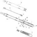
- Figure 1is a perspective view of a nail head assembly of the present invention
- Figure 2ais an exploded view of the nail head assembly of the present invention
- Figure 2bis a front elevational view of the firing block of the nail head assembly of the present invention.
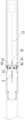
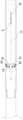
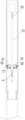
- FIG. 3is a schematic structural view of a longitudinal section of a nail head assembly prior to firing according to the present invention
- FIG. 4is a schematic structural view of the A-A cross section before the nail head assembly of FIG. 3 is fired;
- Figure 5is a schematic view showing the structure of the B-B section before the nail head assembly of Figure 3 is fired;
- Figure 6is a schematic view showing the structure of the A-A section when the nail head assembly of Figure 3 is fired;
- Figure 7is a schematic view showing the structure of the B-B section when the nail head assembly of Figure 3 is fired;
- FIG. 8ais a schematic structural view of a B-B cross section during a knife reset process after the nail head assembly of FIG. 3 is fired;
- Figure 8bis a partial enlarged view of the portion D in Figure 8a;
- FIG. 9is a structural schematic view of a B-B cross section of the nail head assembly of FIG. 3 after the cutter is reset.
- Both the proximal end and the distal end described in the present inventionare referenced by the operator of the instrument, with one end near the operator being the proximal end and one end remote from the operator being the distal end.
- the longitudinal direction in the present inventionrefers to the longitudinal direction of the member, generally from the distal end to the proximal end.
- the transverse directionrefers to the direction perpendicular to the longitudinal direction.
- the description of the direction or position of the upper/upper, lower/lower, vertical, horizontal, etc. in the present inventionis described by taking the drawings as an example, but changes may be made as needed, and the changes are included. It is within the scope of the invention.
- the terms first, second, third, fourth, etc.are used for descriptive purposes only and are not to be understood as indicating or implying a relative importance or implicitly indicating the number of technical features indicated.
- a nail head assemblyincludes a staple cartridge holder, an anvil, a staple cartridge, a firing block, a pusher bar, a cutter, and a safety mechanism.
- the staple cartridge frameis detachably provided with a staple cartridge; the anvil is pivotally closed relative to the staple cartridge; the firing block is movably disposed in the staple cartridge, the firing block is provided with an unlocking member; the cutter is at least Moving relative to the magazine frame in a longitudinal direction thereof between a first position and a second position, a proximal end of the cutter is provided with a pusher bar, and a distal end of the cutter is provided with a blade at the pusher The cutter pushes the firing block to move under the push of the rod; the safety mechanism includes: a safety block, the safety block is disposed in the staple cartridge frame, and the nail can be along the staple cartridge frame The lateral direction of the magazine rack moves between the third position and the fourth position; an elastic member is disposed between the magazine holder and the
- the nail head assemblycomprises: a magazine holder 1, an anvil (not shown), a staple cartridge 2, a firing block 3, a pusher bar 4, a cutter 5, a connecting tube 7, and a safety mechanism .
- the anvilis attached above the cartridge holder 1, preferably the proximal end of the anvil is pivotally coupled to the proximal end 11 of the cartridge holder 1.
- the magazine frame 1is provided with a first limiting groove (feeding groove) 13 and a second limiting groove 14.
- the first limiting slot 13is disposed along the proximal end 11 to the distal end 12 of the cartridge holder 1.
- the second limiting slot 14is disposed at a side of the first limiting slot 13 and communicates with the first limiting slot 13 .
- a second limiting slot 14is defined on both sides of the first limiting slot 13, and the two second limiting slots 14 are symmetrically disposed with respect to the first limiting slot 13.
- the staple cartridge 2is disposed between the staple cartridge holder 1 and the anvil and is detachably coupled to the staple cartridge holder 1. More specifically, the staple cartridge 2 is provided with a nailing hole for accommodating a pusher piece and a staple, generally 4 rows or 6 rows of nail holes, and the anvil is provided with a corresponding nail hole in the staple cartridge The slot is formed for stitching.
- the distal end 71 of the connecting tube 7is connected to the proximal end 11 of the cartridge holder 1.
- the connecting tube 7is formed by splicing the upper connecting member 72 and the lower connecting member 73.
- the pusher bar 4is movably disposed in the connecting tube 7, and the distal end 41 of the pusher bar 4 is connected to the cutter 5.
- the distal end 52 of the cutter 5is also provided with a cutting edge.
- the bladecan cut off the tissue between the anvil and the staple cartridge 2, while the cutter 5 can push the firing block 3 to move, thereby
- the pusher tabsare sequentially pushed out of the staple cartridge 2, which in turn pushes the staples out of the staple cartridge 2 and fits over the tissue.
- the longitudinal section of the cutter 5In the shape of an I-shape, the I-shaped cutter 5 can close the anvil toward the staple cartridge 2 during the process in which the pusher bar 4 pushes the cutter 5 to the distal end.
- the cutter 5is moved along the first limiting slot 13, and the cutter 5 is movable at least relative to the cartridge holder 1 in the longitudinal direction thereof between the first position and the second position, the first position and The second position is two positions along the longitudinal direction of the magazine frame 1, and the first position is closer to the proximal end 11 of the magazine frame 1 relative to the second position.
- the position of the cutter 5 in FIG. 5is the first position, that is, after the staple cartridge 2 is mounted on the magazine holder 1, the cutter 5 is located at the initial position of the proximal end of the magazine holder 1; the position of the cutter 5 in FIG.
- the second positionthat is, the position at which the cutter 5 is moved by the pusher bar 4 to the distal end of the cartridge holder 1 and can no longer continue to move distally.
- the firing block 3is movably disposed within the staple cartridge 2.
- the firing block 3is provided with an unlocking member which is located in the first limiting slot 13. As shown in FIG. 2b, the unlocking member is a protrusion 32 protruding from the bottom of the proximal end 31 of the firing block 3.
- the specific function of the bumps 32can be seen in detail below.
- the insurance mechanismis disposed in the second limiting slot 14, and the insurance mechanism includes a safety block 61 and an elastic member.
- the safety block 61is disposed in the magazine frame 1 and movable between the third position and the fourth position relative to the magazine frame 1.
- the cutter 5can be the first The position is moved to the second position, and when the safety block 61 is in the fourth position, the safety block 61 blocks the cutter 5 from moving from the first position to the second position.
- the upper surface of the safety block 61is provided with a third guiding portion.
- the third guiding portionis a third inclined surface 612 that is inclined on the upper surface of the safety block 61, and from the upper surface thereof A limiting slot 13 is convexly inclined. It can cooperate with the projections 32 on the firing block 3 to facilitate the insertion of the firing block 3 when the staple cartridge 2 is installed.
- the safety block 61moves in the second limiting slot 14, the fourth position is closer to the first limiting slot 13 than the third position, and the position of the safety block 61 in FIG. 4 and FIG.
- the position of the safety block 61is the third position; the position of the safety block 61 in FIG.
- the nail head assemblyincludes two securing mechanisms respectively disposed in the two second limiting slots 14 on both sides of the first limiting slot 13.
- the elastic memberis disposed in the magazine holder 1, and the driving safety block 61 is moved from the third position to the fourth position. As shown in FIG. 5 , the elastic member is further away from the first limiting slot 13 with respect to the safety block 61 , one end of which is connected to the second limiting slot 14 , and the other end is connected to the safety block 61 .
- the resilient memberis preferably a spring 62.
- the spring block 62is disposed in the second limiting slot 14, and one end of the spring block 62 is connected to the inner wall of the magazine frame 1 and the other end is connected to the safety block 61. It is understood by those skilled in the art that in some embodiments, the elastic component can be changed. For example, the elastic component can be disposed in the second limiting slot 14 and protected. The spring between the blocks 61. I will not repeat them here.
- the securing mechanismfurther includes a securing cover 63, the securing member 61 and the resilient member (i.e., the latch 62) are covered by the securing cover 63, located in the second of the securing cover 63 and the cartridge holder 1. Between the limit slots 14.
- the safety fixing cover 63may be provided with a hole through which the screw is fixed in the second limiting groove 14. Further, in the preferred embodiment shown in FIG. 4, the safety fixing cover 63 has a concave portion, and the safety block 61 is further provided with a convex portion 613 which is disposed on the upper surface of the safety block 61 and the convex portion. 613 corresponds.
- the convex portion 613extends upward into the concave portion of the safety fixing cover 63.
- the convex portion 613can effectively prevent the third inclined surface 612 from being reversely disposed due to the assembly of the safety block 61, thereby causing the third inclined surface 612 to be lost. Its guiding function may cause the staple cartridge 2 to be installed in place smoothly.
- FIG. 6 to FIG. 9Please refer to FIG. 6 to FIG. 9 together.
- FIG. 6 and 7are schematic views showing the structures of the cross sections of A-A and B-B when the nail head assembly of Fig. 3 is fired, respectively.
- the cutter 5pushes the firing block 3 under the action of the pusher bar 4
- the firing block 3moves along the first limiting slot 13 toward the distal end 12 of the cartridge holder 1 and is separated from the safety block. 61.
- the cutter 5is moved from the first position to the second position, and the safety block 61 loses lateral compression due to the removal of the unlocking member (ie, the projection 32) on the firing block 3, and thus the elastic member (the elastic member)
- the spring force of 62)is moved to the fourth position (for example, the safety block 61 on both sides is closed, and the gap is smaller than the lateral thickness of the cutter 5).
- the position where the cutter 5 shown in Fig. 7 is locatedis the second position.
- the position of the safety block 61 shown in FIGS. 6 and 7is the fourth position. As shown in FIG. 7, when the safety block 61 is in the fourth position, a portion of the safety block 61 extends into the first limiting groove 13 between the first position and the second position of the cutter 5.
- the nail head assemblyincludes two securing mechanisms disposed on both sides of the first limiting slot 13. Therefore, in this embodiment, the position of the safety block 61 in the fourth position means that the two safety blocks 61 are located in the fourth position, that is, the partial structure of the two safety blocks 61 extends into the first limiting slot 13 and is located at the fourth position. Between a position and a second position. As shown in FIG. 6, when both of the safety blocks 61 are in the fourth position, the spacing between the two safety blocks 61 is smaller than the lateral thickness of the cutter 5.
- the transverse thickness of the cutter 5is less than or equal to the lateral thickness of the projection 32 of the firing block 3, which is more advantageous for the cutter 5 to be moved by the third position at the safety block 61 after the projection 32 of the firing block 3 is removed. Moving from the first position to the second position before the fourth position.
- FIG. 8a and 8bare schematic views showing the structure of the B-B section during the knife reset process after the nail head assembly is fired, and FIG. 8b is a partially enlarged view of the portion D of FIG. 8a.
- the safety block 61has a first guiding portion for guiding the cutter 5 when it is moved from the second position to the first position. The dangerous block 61 is moved from the fourth position to the third position. In the embodiment shown in FIG.
- the first guiding portionis a first inclined surface 611
- the first inclined surface 611is located at the distal end of the safety block 61
- the first inclined surface 611is convex from the distal end toward the first limiting groove 13.
- the slanting typefor example, the safety block 61 has a trapezoidal cross section, and extends from the distal end of the safety block 61 to a side of the safety block 61 close to the first limiting groove 13.
- the safety block 61is moved in the third position direction, and the elastic member (i.e., the spring block 62) is again in a compressed state.
- the safety block 61is completely located on both sides of the cutter 5, the safety block 61 is in the fifth position.
- the transverse thickness of the cutter 5is less than or equal to the lateral thickness of the projection 32 of the firing block 3, and therefore, the fifth position is between the third position and the fourth position.
- the lateral thickness of the cutter 5is the same as the lateral thickness of the projection 32 of the firing block 3, the fifth position is at the same position as the third position.
- the proximal end 51 of the cutter 5may further have a second guiding portion that cooperates with the first guiding portion to guide the movement of the safety block 61 from the fourth position toward the third position.
- the second guiding portionmay be a second inclined surface that is adapted to the first slope 611.
- the second bevelis correspondingly disposed on both sides of the proximal end 51 of the cutter 5. The arrangement of the second bevel is more advantageous for the proximal end 51 of the cutter 5 to laterally press the safety block 61 to move to the third position.
- Fig. 9is a view showing the structure of the B-B section after the cutter is reset.
- the cutter 5in the process of returning the cutter 5 to the first position, when the cutter 5 is moved to a position where the interaction force with the safety block 61 is no longer generated, the cutter 5 is lost between the two safety blocks 61.
- the lateral pressingis again moved to the fourth position by the elastic force of the elastic member (the spring block 62), blocking between the first position and the second position. Since the spacing between the two safety blocks 61 is smaller than the lateral thickness of the cutter 5, and the proximal end of the safety block 61 does not have the guide portion, the safety block 61 blocks the cutter 5 from being the first if a secondary firing is to be performed.
- the positionmoves to the second position, so that the device cannot perform the second firing, and the normal firing can be performed only after replacing the new staple cartridge.
- the projection 32 of the firing block of the new staple cartridgecan be squeezed between the two safety blocks 61 by the guidance of the third inclined surface 612 from above the interval between the two safety blocks 61.
- the safety block 61is forced to return to the third position again, that is, returning to the state shown in FIG. Therefore, if the new staple cartridge 2 is not replaced, the safety block 61 cannot be laterally pressed into the second limit groove 14, the cutter 5 is blocked by the safety block 61, and cannot be moved to the second position again, thereby preventing the nail from being prevented.
- the head assemblyperforms a secondary firing without replacing the staple cartridge.
- the anti-secondary firing structure of the present embodimentmainly utilizes the force of the elastic member (the spring block 62) disposed on both sides of the first limiting slot 13 to the safety block 61, and the unlocking member of the firing block 3 is lost in the safety block 61. After the lateral pressing of the (bumps 32), the safety blocks 61 on both sides are close to each other, thereby preventing the firing of the cutter 5 after being pulled back.
- the nail head assemblycan also function to prevent secondary firing by one of the safety mechanisms.
- one side of the first limiting slot 13is provided with a second limiting slot 14 , and the securing mechanism is disposed in the second limiting slot 14 .
- the safety block 61is oriented.
- the inner wall direction of the corresponding one side of the first limiting groove 13protrudes from the second limiting groove 14 , and the protruding portion of the safety block 61 is located on the moving path of the cutter 5 moving from the first position to the second position, thereby The movement of the cutter 5 to the distal end is restricted.
- one of the insurance mechanismscan also function to prevent secondary firing, which will not be described herein.
- the inventionalso provides a laparoscopic surgical suture cutting device.
- the seam cutting deviceincludes a body and a nail head assembly. among them,
- the bodyincludes a housing and a firing handle disposed within the housing, the nail head assembly being the nail head assembly illustrated in Figures 1-9.
- the connecting tube 7 of the nail head assembly and the pusher bar 4are connected to the body.
- the firing handlecan push the pusher bar 4 to move the cutter 5 toward the distal end 12 of the cartridge holder 1.
- the nail head assembly and the endoscopic surgical slitting deviceprovided by the present invention can effectively prevent the doctor from replacing the stapled cartridge that has been fired. In the case of the next operation, the occurrence of a medical accident is avoided, and the structure of the sewing device is simple and effective.
Landscapes
- Health & Medical Sciences (AREA)
- Life Sciences & Earth Sciences (AREA)
- Surgery (AREA)
- Heart & Thoracic Surgery (AREA)
- Engineering & Computer Science (AREA)
- Biomedical Technology (AREA)
- Nuclear Medicine, Radiotherapy & Molecular Imaging (AREA)
- Medical Informatics (AREA)
- Molecular Biology (AREA)
- Animal Behavior & Ethology (AREA)
- General Health & Medical Sciences (AREA)
- Public Health (AREA)
- Veterinary Medicine (AREA)
- Surgical Instruments (AREA)
- Endoscopes (AREA)
Abstract
Description
本发明涉及医疗器械领域,具体地,涉及一种具有防二次击发的保险机构的钉头组件以及具有该钉头组件的腔镜外科手术缝切装置。The present invention relates to the field of medical devices, and in particular to a nail head assembly having a safety mechanism for preventing secondary firing and a lenticular surgical slitting device having the same.
缝切装置被广泛用于外科手术中的伤口缝合、内部组织缝合与切割。外科手术发展至今,已经越来越倾向于微创手术。广义来讲,能够减少创伤的手术都称为微创手术;狭义来讲,微创手术是指在内窥镜下进行的手术。内窥镜下的手术一般只需要在病人的身体上开几个小孔,将切除、缝合组织及辅助的器械从小孔中深入病人体内进行手术。微创手术给病人带来的创伤小,病人可以在很短的时间内恢复,因此微创手术越来越受到人们的青睐。The slitting device is widely used for wound suturing, internal tissue suturing and cutting in surgery. Since the development of surgery, it has become more and more inclined to minimally invasive surgery. Broadly speaking, surgery that reduces trauma is called minimally invasive surgery; in a narrow sense, minimally invasive surgery refers to surgery performed under endoscopy. Endoscopic surgery generally requires only a few small holes in the patient's body to remove the resected, sutured tissue and auxiliary instruments from the small hole into the patient for surgery. Minimally invasive surgery brings little trauma to the patient, and the patient can recover in a short period of time, so minimally invasive surgery is increasingly favored by people.
现有技术中用于微创手术的腔镜外科手术用直线缝切装置,包括一器械本体,所述器械本体包括壳体及一枢轴设于壳体上的击发把手,该壳体内设有一个可相对移动的击发杆,所述击发杆能推动位于壳体前端的钉头组件进行缝合和切除。具体的,所述钉头组件包括一钉仓架,及一与钉仓架枢轴连接的钉砧。所述钉仓架上可拆卸地设有钉仓,钉仓内设有一组内设有推钉片、吻合钉的置钉孔,一般为4排或6排的置钉孔。所述钉砧在与所述置钉孔相对的位置上设有钉成型槽。所述钉头组件还包括一个可移动地设置在钉头组件的接管内的、与击发杆配接的推刀杆,所述推刀杆的远端固定一工字型切刀,该工字型切刀在前进的过程中将钉仓和钉砧闭合。所述切刀的远端中心设有刀刃,其在前进的过程中将位于钉仓和钉砧间的组织切断。钉仓内设有击发块,在工字型切刀前进的过程中,工字型切刀驱动击发块将推钉片依次推出于钉仓外,进而推钉片将吻合钉推出于钉仓外并订合在组织上。现有技术中,医生完成上述的缝切动作后,首先需要将器械复位,继而更换钉仓,以便腔镜外科手术用缝切装置进行下一次的缝切手术。A linear slitting device for laparoscopic surgery for minimally invasive surgery includes a device body, and the instrument body includes a housing and a firing handle pivotally disposed on the housing, wherein the housing is provided with a firing handle A relatively movable firing bar that urges the nail head assembly at the front end of the housing for stitching and cutting. Specifically, the nail head assembly includes a staple cartridge holder and an anvil pivotally coupled to the staple cartridge holder. The staple cartridge frame is detachably provided with a staple cartridge, and the staple cartridge is provided with a set of nailing holes provided with push nails and staples, generally 4 rows or 6 rows of nail holes. The anvil is provided with a nail forming groove at a position opposite to the nailing hole. The nail head assembly further includes a pusher bar movably disposed in the socket of the nail head assembly and coupled to the firing rod, the distal end of the pusher bar is fixed with an I-shaped cutter, the type The cutter cuts the staple cartridge and the anvil during the advancement process. The distal end of the cutter is provided with a cutting edge that cuts tissue between the staple cartridge and the anvil during advancement. There is a firing block in the staple cartridge. During the advancement of the I-shaped cutter, the I-shaped cutter drives the firing block to push the pusher pieces out of the staple cartridge in turn, and then pushes the staples to push the staples out of the staple cartridge. And contracted in the organization. In the prior art, after the doctor completes the above-mentioned suture cutting operation, it is first necessary to reset the instrument and then replace the staple cartridge, so that the suture surgery device can perform the next suture cutting operation.
但是由于一些粗心的医生或者经验不足的医生,会在未更换已击发的钉仓的情况下进行下一次的缝切手术,这样会导致医疗事故的产生,即进行了切除却没有缝合。为了防止此类事故的发生,提出了使用二次保险防二次击发的理论,即在未更换已击发的钉仓的情况下,击发把手不能被按动。这样,从根本上防止了由于医生误操作而产生的医疗事故。However, because some careless doctors or inexperienced doctors will perform the next suture operation without replacing the stapled staples, this will lead to a medical accident, that is, the resection is performed without suturing. In order to prevent such accidents from occurring, the theory of using secondary insurance against secondary firing is proposed, that is, the firing handle cannot be pressed without replacing the fired staple cartridge. In this way, medical accidents caused by doctors' misoperations are fundamentally prevented.
发明内容Summary of the invention
本发明提供一种钉头组件以及腔镜外科手术缝切装置,可以有效防止缝切装置在未更换钉仓的情况下被二次击发。The invention provides a nail head assembly and a lenticular surgical suture cutting device, which can effectively prevent the sewing device from being secondarily fired without replacing the staple cartridge.
根据本发明的一个方面,提供一种钉头组件,所述钉头组件包括:钉仓架,可拆卸地设有钉仓;钉砧,可相对于钉仓枢转闭合;击发块,可移动地设置于所述钉仓内,所述击发块设有一解锁部件;切刀,所述切刀至少可相对所述钉仓架沿其纵向在第一位置与第二位置之间移动,所述切刀的近端设置有推刀杆,所述切刀的远端设有刀刃,在所述推刀杆的推动下,所述切刀推动所述击发块移动;保险机构,所述保险机构包括:保险块,所述保险块设置于所述钉仓架内,且可相对所述钉仓架沿所述钉仓架的横向在第三位置与第四位置之间移动;弹性部件,设置于所述钉仓架与所述保险块之间,驱动所述保险块由所述第三位置向所述第四位置移动;在所述击发块被所述切刀击发移动前,所述解锁部件横向挤压所述保险块处于所述第三位置,所述弹性部件处于压缩状态,所述切刀可由所述第一位置移动至所述第二位置;在所述击发块被所述切刀击发移动后,所述保险块在所述弹性部件的作用下移动至所述第四位置,所述保险块阻挡所述切刀由所述第一位置移动至所述第二位置。According to an aspect of the invention, a nail head assembly is provided, the nail head assembly comprising: a staple cartridge holder detachably provided with a staple cartridge; an anvil pivotally closed relative to the staple cartridge; a firing block movable Positioned in the staple cartridge, the firing block is provided with an unlocking member; a cutter that is movable at least relative to the cartridge holder in a longitudinal direction thereof between a first position and a second position, a proximal end of the cutter is provided with a pusher bar, the distal end of the cutter is provided with a blade, and the cutter pushes the firing block to move under the pushing of the pusher bar; the insurance mechanism, the insurance mechanism The utility model comprises: a safety block, the safety block is disposed in the magazine frame, and is movable between a third position and a fourth position along a lateral direction of the magazine frame relative to the magazine frame; elastic component, setting Between the magazine holder and the safety block, driving the safety block to move from the third position to the fourth position; before the firing block is fired by the cutter, the unlocking The member laterally squeezing the safety block in the third position, the elastic member In a compressed state, the cutter is movable from the first position to the second position; after the firing block is moved by the cutter, the safety block is moved by the elastic member to the In the fourth position, the safety block blocks the cutter from moving from the first position to the second position.
本发明实施例中,所述钉仓架具有一沿其纵向设置的第一限位槽,所述切刀以及所述击发块可沿所述第一限位槽移动。In the embodiment of the invention, the magazine holder has a first limiting slot disposed along a longitudinal direction thereof, and the cutter and the firing block are movable along the first limiting slot.
本发明实施例中,所述钉仓架还具有一沿其横向设置的第二限位槽,所述第二限位槽与所述第一限位槽相通,所述保险机构设置于所述第二限位槽内,所述保险块于所述第二限位槽内移动,所述第三位置相对所述第四位置更远离所述第一限位槽。In the embodiment of the present invention, the magazine frame further has a second limiting slot disposed along a lateral direction thereof, the second limiting slot is in communication with the first limiting slot, and the insurance mechanism is disposed on the In the second limiting slot, the safety block moves in the second limiting slot, and the third position is further away from the first limiting slot than the fourth position.
本发明实施例中,在所述击发块被所述切刀击发移动后,所述保险块在所述弹性部件的作用下伸入所述第一限位槽,到达所述第四位置,介于所述切刀的第一位置与第二位置之间,并且所述切刀位于所述保险块的远端侧;在所述切刀被拉回至所述钉仓的近端后,所述保险块在所述弹性部件的作用下保持在所述第四位置,所述切刀位于所述保险块的近端侧。In the embodiment of the present invention, after the firing block is shot and moved by the cutter, the safety block protrudes into the first limiting slot by the elastic component, and reaches the fourth position. Between the first position and the second position of the cutter, and the cutter is located on a distal end side of the safety block; after the cutter is pulled back to the proximal end of the staple cartridge, The safety block is held in the fourth position by the elastic member, and the cutter is located on the proximal side of the safety block.
本发明实施例中,所述弹性部件为一弹块,所述弹块相对所述保险块更远离所述第一限位槽,其一端连接所述钉仓架内壁,另一端连接所述保险块。In the embodiment of the present invention, the elastic member is a spring block, and the elastic block is farther away from the first limiting slot than the safety block, one end of which is connected to the inner wall of the nail cartridge frame, and the other end is connected to the insurance. Piece.
本发明实施例中,所述解锁部件为一凸设于所述击发块近端的底部的凸块。In the embodiment of the invention, the unlocking component is a protrusion protruding from a bottom of the proximal end of the firing block.
本发明实施例中,所述第一限位槽的两侧各设有一第二限位槽,所述钉头组件包括两个保险机构,分别设置于两个所述第二限位槽内,当两个所述保险块均位于第四位置时,两个所述保险块之间的间距小于所述切刀的横向厚度。In the embodiment of the present invention, a second limiting slot is disposed on each side of the first limiting slot, and the nail head assembly includes two securing mechanisms respectively disposed in the two second limiting slots. When both of the safety blocks are in the fourth position, the spacing between the two safety blocks is smaller than the lateral thickness of the cutter.
本发明实施例中,所述切刀为纵截面呈工字形的工字刀,在所述推刀杆推动所述切刀往远端移动的过程中,所述工字刀的顶部使所述钉砧朝向所述钉仓闭合;当所述钉砧和钉仓闭合且所述保险块位于第三位置时,所述切刀的第一位置比所述击发块更靠近所述钉仓架的近端。In the embodiment of the present invention, the cutter is an I-shaped cutter having an I-shaped longitudinal section, and the top of the I-shaped cutter causes the top of the I-shaped cutter to move the cutter to the distal end during the movement of the cutter An anvil is closed toward the staple cartridge; a first position of the cutter is closer to the cartridge holder than the firing block when the anvil and staple cartridge are closed and the safety block is in a third position Near end.
本发明实施例中,所述保险块具有一第一引导部,当所述切刀由所述第二位置移动至所述第一位置时,引导所述保险块由所述第四位置向第三位置方向移动。In the embodiment of the present invention, the safety block has a first guiding portion, and when the cutter moves from the second position to the first position, guiding the safety block from the fourth position to the first position Move in the three position direction.
本发明实施例中,所述第一引导部为一第一斜面,所述第一斜面设置于所述保险块的远端,且自远端朝向第一限位槽方向凸出式倾斜。In the embodiment of the present invention, the first guiding portion is a first inclined surface, and the first inclined surface is disposed on the safety blockThe distal end is convexly inclined from the distal end toward the first limiting slot.
本发明实施例中,所述保险块具有一第三引导部,当所述钉仓安装时,引导所述保险块由所述第四位置向第三位置方向移动。In the embodiment of the present invention, the safety block has a third guiding portion, and when the staple cartridge is installed, the safety block is guided to move from the fourth position to the third position.
本发明实施例中,所述第三引导部为一第三斜面,所述第三斜面设置于所述保险块的上表面上,且自上表面朝向第一限位槽方向凸出式倾斜。In the embodiment of the present invention, the third guiding portion is a third inclined surface, and the third inclined surface is disposed on the upper surface of the safety block, and is convexly inclined from the upper surface toward the first limiting groove.
本发明实施例中,所述保险机构还包括保险固定盖,所述保险块和所述弹性部件被覆盖于所述保险固定盖与所述钉仓架之间。In an embodiment of the invention, the insurance mechanism further includes a safety fixing cover, and the safety block and the elastic member are covered between the safety fixing cover and the magazine holder.
本发明实施例中,所述保险固定盖具有一凹部,所述保险块还设有一凸起部,所述凸起部设置于所述保险块的上表面,对应延伸入所述凹部中。In the embodiment of the present invention, the safety fixing cover has a concave portion, and the safety block is further provided with a convex portion, and the convex portion is disposed on the upper surface of the safety block and correspondingly extends into the concave portion.
根据本发明的另一个方面,还包括一种腔镜外科手术缝切装置,其特征在于,包括上述的钉头组件。According to another aspect of the present invention, a laparoscopic surgical slitting device is further included, comprising the above-described nail head assembly.
本发明通过提供一种钉头组件以及腔镜外科手术缝切装置,可以有效地防止医生在未更换已击发的钉仓的情况下进行下一次的手术,避免医疗事故的产生,并且该缝切装置结构简单有效。The invention provides a nail head assembly and a laparoscopic surgical suture cutting device, which can effectively prevent the doctor from performing the next operation without replacing the fired staple cartridge, avoiding the occurrence of a medical accident, and the slitting The device structure is simple and effective.
通过阅读参照以下附图对非限制性实施例所作的详细描述,本发明的其它特征、目的和优点将会变得更明显:Other features, objects, and advantages of the present invention will become apparent from the Detailed Description of Description
图1为本发明的钉头组件的立体图;Figure 1 is a perspective view of a nail head assembly of the present invention;
图2a为本发明的钉头组件的爆炸图;Figure 2a is an exploded view of the nail head assembly of the present invention;
图2b为本发明的钉头组件的击发块的主视图;Figure 2b is a front elevational view of the firing block of the nail head assembly of the present invention;
图3为本发明的钉头组件击发前的纵截面的结构示意图;3 is a schematic structural view of a longitudinal section of a nail head assembly prior to firing according to the present invention;
图4为图3中的钉头组件击发前的A-A截面的结构示意图;4 is a schematic structural view of the A-A cross section before the nail head assembly of FIG. 3 is fired;
图5为图3中的钉头组件击发前的B-B截面的结构示意图;Figure 5 is a schematic view showing the structure of the B-B section before the nail head assembly of Figure 3 is fired;
图6为图3中的钉头组件击发时的A-A截面的结构示意图;Figure 6 is a schematic view showing the structure of the A-A section when the nail head assembly of Figure 3 is fired;
图7为图3中的钉头组件击发时的B-B截面的结构示意图;Figure 7 is a schematic view showing the structure of the B-B section when the nail head assembly of Figure 3 is fired;
图8a为图3中的钉头组件击发后切刀复位过程中的B-B横截面的结构示意图;8a is a schematic structural view of a B-B cross section during a knife reset process after the nail head assembly of FIG. 3 is fired;
图8b为图8a中D处的局部放大示意图;以及Figure 8b is a partial enlarged view of the portion D in Figure 8a;
图9为图3中的钉头组件的切刀复位后的B-B横截面的结构示意图。9 is a structural schematic view of a B-B cross section of the nail head assembly of FIG. 3 after the cutter is reset.
本发明内所描述的近端和远端,均是以器械操作者作为参照,靠近操作者的一端为近端,远离操作者的一端为远端。本发明中的纵向是指部件长度方向,大致从远端到近端的方向。横向是指垂直所述纵向的方向。本发明中的上方/上、下方/下、竖直、水平等对方向或位置的描述是以附图为例进行的说明,但根据需要也可以做出改变,所做改变均包含在本发明保护范围内。此外,术语第一、第二、第三、第四等仅用于描述目的,而不能理解为指示或暗示相对重要性或者隐含指明所指示的技术特征的数量。Both the proximal end and the distal end described in the present invention are referenced by the operator of the instrument, with one end near the operator being the proximal end and one end remote from the operator being the distal end. The longitudinal direction in the present invention refers to the longitudinal direction of the member, generally from the distal end to the proximal end. The transverse direction refers to the direction perpendicular to the longitudinal direction. The description of the direction or position of the upper/upper, lower/lower, vertical, horizontal, etc. in the present invention is described by taking the drawings as an example, but changes may be made as needed, and the changes are included.It is within the scope of the invention. Moreover, the terms first, second, third, fourth, etc. are used for descriptive purposes only and are not to be understood as indicating or implying a relative importance or implicitly indicating the number of technical features indicated.
依据本发明主旨构思,钉头组件包括钉仓架、钉砧、钉仓、击发块、推刀杆、切刀以及保险机构。钉仓架可拆卸地设有钉仓;钉砧可相对于钉仓枢转闭合;击发块可移动地设置于所述钉仓内,所述击发块设有一解锁部件;所述切刀至少可相对所述钉仓架沿其纵向在第一位置与第二位置之间移动,所述切刀的近端设置有推刀杆,所述切刀的远端设有刀刃,在所述推刀杆的推动下,所述切刀推动所述击发块移动;所述保险机构包括:保险块,所述保险块设置于所述钉仓架内,且可相对所述钉仓架沿所述钉仓架的横向在第三位置与第四位置之间移动;弹性部件,设置于所述钉仓架与所述保险块之间,驱动所述保险块由所述第三位置向所述第四位置移动;在所述击发块被所述切刀击发移动前,所述解锁部件横向挤压所述保险块使其处于所述第三位置,所述弹性部件处于压缩状态,所述切刀可由所述第一位置移动至所述第二位置;在所述击发块被所述切刀击发移动后,所述保险块在所述弹性部件的作用下移动至所述第四位置,所述保险块阻挡所述切刀由所述第一位置移动至所述第二位置。In accordance with the teachings of the present invention, a nail head assembly includes a staple cartridge holder, an anvil, a staple cartridge, a firing block, a pusher bar, a cutter, and a safety mechanism. The staple cartridge frame is detachably provided with a staple cartridge; the anvil is pivotally closed relative to the staple cartridge; the firing block is movably disposed in the staple cartridge, the firing block is provided with an unlocking member; the cutter is at least Moving relative to the magazine frame in a longitudinal direction thereof between a first position and a second position, a proximal end of the cutter is provided with a pusher bar, and a distal end of the cutter is provided with a blade at the pusher The cutter pushes the firing block to move under the push of the rod; the safety mechanism includes: a safety block, the safety block is disposed in the staple cartridge frame, and the nail can be along the staple cartridge frame The lateral direction of the magazine rack moves between the third position and the fourth position; an elastic member is disposed between the magazine holder and the safety block, and drives the safety block from the third position to the fourth position a positional movement; the unlocking member laterally presses the safety block to be in the third position, the elastic member is in a compressed state, and the cutter may be in a compressed state before the firing block is moved by the cutter The first position is moved to the second position; the firing block is cut After firing movement, under the action of the resilient member of the safety block is moved to the fourth position, the second safety block position blocking the movement of said cutter from said first position to.
下面结合附图和实施例对本发明的技术内容进行进一步地说明:The technical content of the present invention will be further described below with reference to the accompanying drawings and embodiments:
请一并参见图1至图5,其分别示出了本发明的钉头组件的立体图、爆炸图以及击发前钉头组件的各截面处的结构示意图。其中,由于钉头组件的钉砧不是本发明的创新部分,因此,为了更清楚地显示钉头组件的结构,附图中均省略了钉头组件的钉砧。在本发明的优选实施例中,钉头组件包括:钉仓架1、钉砧(未示出)、钉仓2、击发块3、推刀杆4、切刀5、连接管7以及保险机构。其中,所述钉砧连接于钉仓架1的上方,优选地,钉砧的近端与钉仓架1的近端11枢轴连接。1 to 5, which respectively show a perspective view, an exploded view of the nail head assembly of the present invention, and a structural schematic view of each section of the nail head assembly before firing. Wherein, since the anvil of the nail head assembly is not an innovative part of the present invention, the anvil of the nail head assembly is omitted in the drawings in order to more clearly show the structure of the nail head assembly. In a preferred embodiment of the invention, the nail head assembly comprises: amagazine holder 1, an anvil (not shown), astaple cartridge 2, afiring block 3, apusher bar 4, acutter 5, a connectingtube 7, and a safety mechanism . Wherein the anvil is attached above thecartridge holder 1, preferably the proximal end of the anvil is pivotally coupled to theproximal end 11 of thecartridge holder 1.
如图2a和图5所示,钉仓架1设有第一限位槽(走刀槽)13和第二限位槽14。第一限位槽13沿钉仓架1近端11至远端12设置。第二限位槽14设置于第一限位槽13的侧部,且与第一限位槽13相通。在图2a所示的优选实施例中,第一限位槽13的两侧均设有一第二限位槽14,两个第二限位槽14相对第一限位槽13对称设置。As shown in FIG. 2a and FIG. 5, themagazine frame 1 is provided with a first limiting groove (feeding groove) 13 and a second limitinggroove 14. The first limitingslot 13 is disposed along theproximal end 11 to thedistal end 12 of thecartridge holder 1. The second limitingslot 14 is disposed at a side of the first limitingslot 13 and communicates with the first limitingslot 13 . In the preferred embodiment shown in FIG. 2a, a second limitingslot 14 is defined on both sides of the first limitingslot 13, and the two second limitingslots 14 are symmetrically disposed with respect to the first limitingslot 13.
钉仓2设置于钉仓架1与所述钉砧之间,且可拆卸地连接钉仓架1。更具体地,钉仓2内设有容纳推钉片和吻合钉的置钉孔,一般为4排或6排置钉孔,所述钉砧上设有与钉仓内的置钉孔对应的钉成型槽,以便进行缝合。Thestaple cartridge 2 is disposed between thestaple cartridge holder 1 and the anvil and is detachably coupled to thestaple cartridge holder 1. More specifically, thestaple cartridge 2 is provided with a nailing hole for accommodating a pusher piece and a staple, generally 4 rows or 6 rows of nail holes, and the anvil is provided with a corresponding nail hole in the staple cartridge The slot is formed for stitching.
连接管7的远端71连接钉仓架1的近端11。如图2a所示,优选地,连接管7由上连接件72和下连接件73拼接而成。Thedistal end 71 of the connectingtube 7 is connected to theproximal end 11 of thecartridge holder 1. As shown in Fig. 2a, preferably, the connectingtube 7 is formed by splicing the upper connectingmember 72 and the lower connectingmember 73.
推刀杆4可移动地设置于连接管7内,推刀杆4的远端41连接有切刀5。切刀5远端52还设有刀刃。在所述推刀杆4推动切刀5向远端移动的过程中,刀刃可以切断位于钉砧和钉仓2之间的组织,与此同时,切刀5可以推动击发块3移动,从而将推钉片依次推出钉仓2,进而将吻合钉推出钉仓2并订合于组织上。在本实施例中,切刀5的纵截面呈工字形,在所述推刀杆4推动切刀5往远端移动的过程中,工字形的切刀5可使钉砧朝向钉仓2闭合。Thepusher bar 4 is movably disposed in the connectingtube 7, and thedistal end 41 of thepusher bar 4 is connected to thecutter 5. Thedistal end 52 of thecutter 5 is also provided with a cutting edge. During the pushing of thecutter bar 4 to move thecutter 5 to the distal end, the blade can cut off the tissue between the anvil and thestaple cartridge 2, while thecutter 5 can push thefiring block 3 to move, thereby The pusher tabs are sequentially pushed out of thestaple cartridge 2, which in turn pushes the staples out of thestaple cartridge 2 and fits over the tissue. In the present embodiment, the longitudinal section of thecutter 5In the shape of an I-shape, the I-shapedcutter 5 can close the anvil toward thestaple cartridge 2 during the process in which thepusher bar 4 pushes thecutter 5 to the distal end.
如图3和图5所示,切刀5沿第一限位槽13移动,切刀5至少可相对钉仓架1沿其纵向在第一位置与第二位置之间移动,第一位置和第二位置为沿钉仓架1纵向上的两个位置,且第一位置相对于第二位置更靠近钉仓架1的近端11。图5中的切刀5所在位置为第一位置,即将钉仓2安装于钉仓架1上后,切刀5位于钉仓架1近端的初始位置;图7中的切刀5所在位置为第二位置,也即切刀5在推刀杆4的作用下移动至钉仓架1的远端且不能再继续向远端移动时的位置。As shown in FIG. 3 and FIG. 5, thecutter 5 is moved along the first limitingslot 13, and thecutter 5 is movable at least relative to thecartridge holder 1 in the longitudinal direction thereof between the first position and the second position, the first position and The second position is two positions along the longitudinal direction of themagazine frame 1, and the first position is closer to theproximal end 11 of themagazine frame 1 relative to the second position. The position of thecutter 5 in FIG. 5 is the first position, that is, after thestaple cartridge 2 is mounted on themagazine holder 1, thecutter 5 is located at the initial position of the proximal end of themagazine holder 1; the position of thecutter 5 in FIG. The second position, that is, the position at which thecutter 5 is moved by thepusher bar 4 to the distal end of thecartridge holder 1 and can no longer continue to move distally.
击发块3可移动地设置于钉仓2内。击发块3设有一解锁部件,所述解锁部件位于第一限位槽13内。如图2b所示,所述解锁部件为一凸设于击发块3近端31的底部的凸块32。凸块32的具体作用可详见下文。Thefiring block 3 is movably disposed within thestaple cartridge 2. Thefiring block 3 is provided with an unlocking member which is located in the first limitingslot 13. As shown in FIG. 2b, the unlocking member is aprotrusion 32 protruding from the bottom of theproximal end 31 of thefiring block 3. The specific function of thebumps 32 can be seen in detail below.
保险机构设置于第二限位槽14内,所述保险机构包括保险块61以及弹性部件。The insurance mechanism is disposed in the second limitingslot 14, and the insurance mechanism includes asafety block 61 and an elastic member.
保险块61设置于钉仓架1内,且可相对钉仓架1在第三位置与第四位置之间移动,在保险块61处于所述第三位置时,切刀5可由所述第一位置移动至所述第二位置,在保险块61处于所述第四位置时,保险块61阻挡切刀5由所述第一位置移动至所述第二位置。Thesafety block 61 is disposed in themagazine frame 1 and movable between the third position and the fourth position relative to themagazine frame 1. When thesafety block 61 is in the third position, thecutter 5 can be the first The position is moved to the second position, and when thesafety block 61 is in the fourth position, thesafety block 61 blocks thecutter 5 from moving from the first position to the second position.
更具体地,保险块61的上表面设有第三引导部,在本实施例中,第三引导部为在保险块61的上表面上倾斜设置的第三斜面612,且自其上表面第一限位槽13方向凸出式倾斜。其可与击发块3上的凸块32相配合,便于钉仓2安装时击发块3的插入。保险块61于第二限位槽14内移动,所述第四位置相对所述第三位置更靠近第一限位槽13,图4和图5中保险块61所在位置为第三位置,也即将钉仓2安装于钉仓架1的过程中,位于钉仓2近端的击发块3上的凸块32沿着第三斜面612横向挤压保险块61,保险块61进而挤压弹性部件发生弹性形变,最终使保险块61避开切刀5自第一位置移动至第二位置时的移动路线,此时保险块61所在位置即为第三位置;图7中保险块61所在位置为第四位置,具体地,在推动推刀杆4带动切刀5自第一位置向第二位置移动的过程中,切刀5推动击发块3同时向钉仓2的远端移动,使得击发块3逐渐解除对保险块61的挤压作用,当击发块3和切刀5继续向远端运动至不再与保险块61产生相互作用后,保险块61不再受到任何限制,在弹性部件的作用下沿着第二限位槽14移动,且部分保险块61进入第一限位槽13,使得保险块61阻挡于切刀5在第一位置与第二位置之间的移动路线上。如图4和图5所示,优选地,所述钉头组件包括两个保险机构,分别设置于第一限位槽13的两侧的两个第二限位槽14内。More specifically, the upper surface of thesafety block 61 is provided with a third guiding portion. In the present embodiment, the third guiding portion is a thirdinclined surface 612 that is inclined on the upper surface of thesafety block 61, and from the upper surface thereof A limitingslot 13 is convexly inclined. It can cooperate with theprojections 32 on thefiring block 3 to facilitate the insertion of thefiring block 3 when thestaple cartridge 2 is installed. Thesafety block 61 moves in the second limitingslot 14, the fourth position is closer to the first limitingslot 13 than the third position, and the position of thesafety block 61 in FIG. 4 and FIG. 5 is the third position, In the process of installing thestaple cartridge 2 in thestaple cartridge holder 1, theprojection 32 on thefiring block 3 at the proximal end of thestaple cartridge 2 laterally presses thesafety block 61 along the thirdinclined surface 612, and thesafety block 61 further presses the elastic member. The elastic deformation occurs, and finally thesafety block 61 avoids the movement route when thecutter 5 is moved from the first position to the second position. At this time, the position of thesafety block 61 is the third position; the position of thesafety block 61 in FIG. 7 is The fourth position, specifically, in the process of pushing thepusher bar 4 to move thecutter 5 from the first position to the second position, thecutter 5 pushes thefiring block 3 while moving toward the distal end of thestaple cartridge 2, so that thefiring block 3 gradually releasing the pressing action on thesafety block 61. When thefiring block 3 and thecutting blade 5 continue to move distally until no longer interact with thesafety block 61, thesafety block 61 is no longer subject to any restrictions on the elastic member. Moving along the second limitingslot 14 and a portion of thesafety block 61 entering the first limitingslot 13 Such that thesafety barrier 61 on thecutter block 5 is moved in a path between a first position and a second position. As shown in FIG. 4 and FIG. 5, the nail head assembly includes two securing mechanisms respectively disposed in the two second limitingslots 14 on both sides of the first limitingslot 13.
弹性部件设置于钉仓架1内,驱动保险块61由第三位置向第四位置移动。如图5所示,所述弹性部件相对保险块61更远离第一限位槽13,其一端连接第二限位槽14,另一端连接保险块61。弹性部件优选地为一弹块62。弹块62设置于第二限位槽14内,弹块62的一端连接钉仓架1内壁,另一端连接保险块61。本领域技术人员理解,在一些实施例中,弹性部件是可以进行变化的,例如,弹性部件可以是一设置于第二限位槽14与保险块61之间的弹簧。在此不予赘述。The elastic member is disposed in themagazine holder 1, and the drivingsafety block 61 is moved from the third position to the fourth position. As shown in FIG. 5 , the elastic member is further away from the first limitingslot 13 with respect to thesafety block 61 , one end of which is connected to the second limitingslot 14 , and the other end is connected to thesafety block 61 . The resilient member is preferably aspring 62. Thespring block 62 is disposed in the second limitingslot 14, and one end of thespring block 62 is connected to the inner wall of themagazine frame 1 and the other end is connected to thesafety block 61. It is understood by those skilled in the art that in some embodiments, the elastic component can be changed. For example, the elastic component can be disposed in the second limitingslot 14 and protected.The spring between theblocks 61. I will not repeat them here.
在图2a的优选实施例中,保险机构还包括保险固定盖63,保险块61和弹性部件(即弹块62)被保险固定盖63覆盖,位于保险固定盖63与钉仓架1的第二限位槽14之间。保险固定盖63上可以设有孔,供螺丝穿过所述孔而固定于第二限位槽14中。进一步地,在图4所示的优选实施例中,保险固定盖63具有一凹部,保险块61还设有一凸起部613,凸起部613设置于保险块61的上表面,与凸起部613相对应。凸起部613向上延伸入保险固定盖63的凹部中,凸起部613可有效地避免因保险块61装配时装反,而使其第三斜面612随之反向设置,造成第三斜面612丧失其引导功能,有可能导致钉仓2无法顺利地被安装到位的情况发生。In the preferred embodiment of Fig. 2a, the securing mechanism further includes a securingcover 63, the securingmember 61 and the resilient member (i.e., the latch 62) are covered by the securingcover 63, located in the second of the securingcover 63 and thecartridge holder 1. Between thelimit slots 14. Thesafety fixing cover 63 may be provided with a hole through which the screw is fixed in the second limitinggroove 14. Further, in the preferred embodiment shown in FIG. 4, thesafety fixing cover 63 has a concave portion, and thesafety block 61 is further provided with aconvex portion 613 which is disposed on the upper surface of thesafety block 61 and the convex portion. 613 corresponds. Theconvex portion 613 extends upward into the concave portion of thesafety fixing cover 63. Theconvex portion 613 can effectively prevent the thirdinclined surface 612 from being reversely disposed due to the assembly of thesafety block 61, thereby causing the thirdinclined surface 612 to be lost. Its guiding function may cause thestaple cartridge 2 to be installed in place smoothly.
进一步地,请参见图4和图5,当将钉仓2安装于钉仓架1上后且钉头组件击发前,切刀5位于第一位置,位于钉仓2近端的击发块3的解锁部件(即凸块32)横向挤压保险块61使其位于所述第三位置,保险块61受到凸块32的止挡进而使弹性部件(即弹块62)处于压缩状态,此时,推动推刀杆4可驱动切刀5和击发块3向远端移动,以便对组织进行切割和缝合。Further, referring to FIG. 4 and FIG. 5, when thestaple cartridge 2 is mounted on thecartridge holder 1 and before the nail head assembly is fired, thecutter 5 is located at the first position, and thefiring block 3 at the proximal end of thestaple cartridge 2 is The unlocking member (ie, the projection 32) laterally presses thesafety block 61 to be in the third position, and thesafety block 61 is stopped by theprojection 32 to further compress the elastic member (ie, the spring block 62). Pushing thepusher bar 4 can drive thecutter 5 and thefiring block 3 to move distally to cut and stitch the tissue.
更进一步地,请一并参见图6至图9。Further, please refer to FIG. 6 to FIG. 9 together.
图6和图7分别示出了图3中的钉头组件击发时的A-A和B-B的截面的结构示意图。如图6和图7所示,当切刀5在推刀杆4作用下推动击发块3后,击发块3沿第一限位槽13向钉仓架1的远端12移动并脱离保险块61。在此过程中,切刀5由第一位置移动至第二位置,保险块61由于击发块3上的解锁部件(即凸块32)移开而失去横向挤压,进而在弹性部件(弹块62)的弹力作用下移动至第四位置(例如两侧的保险块61闭合,间隙小于切刀5的横向厚度)。图7中所示的切刀5所在的位置即为第二位置。同时,图6和图7中所示的保险块61的位置即为第四位置。如图7所示,当保险块61位于第四位置时,部分保险块61伸入第一限位槽13,位于切刀5的第一位置与第二位置之间。6 and 7 are schematic views showing the structures of the cross sections of A-A and B-B when the nail head assembly of Fig. 3 is fired, respectively. As shown in FIG. 6 and FIG. 7, when thecutter 5 pushes thefiring block 3 under the action of thepusher bar 4, thefiring block 3 moves along the first limitingslot 13 toward thedistal end 12 of thecartridge holder 1 and is separated from the safety block. 61. During this process, thecutter 5 is moved from the first position to the second position, and thesafety block 61 loses lateral compression due to the removal of the unlocking member (ie, the projection 32) on thefiring block 3, and thus the elastic member (the elastic member) The spring force of 62) is moved to the fourth position (for example, thesafety block 61 on both sides is closed, and the gap is smaller than the lateral thickness of the cutter 5). The position where thecutter 5 shown in Fig. 7 is located is the second position. Meanwhile, the position of thesafety block 61 shown in FIGS. 6 and 7 is the fourth position. As shown in FIG. 7, when thesafety block 61 is in the fourth position, a portion of thesafety block 61 extends into the first limitinggroove 13 between the first position and the second position of thecutter 5.
进一步地,由于本发明的优选实施例中,所述钉头组件包括了设置于第一限位槽13两侧的两个保险机构。因此,在此实施例中,保险块61位于第四位置是指两个保险块61均位于第四位置,即两个保险块61的部分结构伸入第一限位槽13且位于所述第一位置与第二位置之间。如图6所示,当两个保险块61均位于第四位置时,两个保险块61之间的间距小于切刀5的横向厚度。Further, in a preferred embodiment of the present invention, the nail head assembly includes two securing mechanisms disposed on both sides of the first limitingslot 13. Therefore, in this embodiment, the position of thesafety block 61 in the fourth position means that the twosafety blocks 61 are located in the fourth position, that is, the partial structure of the twosafety blocks 61 extends into the first limitingslot 13 and is located at the fourth position. Between a position and a second position. As shown in FIG. 6, when both of the safety blocks 61 are in the fourth position, the spacing between the twosafety blocks 61 is smaller than the lateral thickness of thecutter 5.
优选地,切刀5的横向厚度小于等于击发块3的凸块32的横向厚度,更有利于当击发块3的凸块32移开后,切刀5能够在保险块61由第三位置移动至第四位置之前由第一位置移动至第二位置。Preferably, the transverse thickness of thecutter 5 is less than or equal to the lateral thickness of theprojection 32 of thefiring block 3, which is more advantageous for thecutter 5 to be moved by the third position at thesafety block 61 after theprojection 32 of thefiring block 3 is removed. Moving from the first position to the second position before the fourth position.
进一步地,当完成对组织的切割、缝合后,切刀5需进行复位返回击发前的第一位置,击发块3停留在钉仓的远端。图8a和图8b示出了钉头组件击发后切刀复位过程中的B-B截面的结构示意图,图8b为图8a的D处的局部放大示意图。如图8a和8b所示,保险块61具有一第一引导部,第一引导部用于当切刀5由第二位置移动至第一位置时,引导保险块61由第四位置向第三位置方向移动。在图8b所示实施例中,所述第一引导部为一第一斜面611,第一斜面611位于保险块61的远端,第一斜面611自远端朝向第一限位槽13方向凸出式倾斜,例如保险块61的横截面为梯形,以保险块61的远端为起点延伸至保险块61靠近第一限位槽13的一侧面。当切刀5由第二位置向第一位置方向移动至保险块61的远端位置时,切刀5推动第一斜面611,第一斜面611产生的沿第二限位槽14方向的分力使保险块61向第三位置方向移动,弹性部件(即弹块62)再次处于压缩状态。当保险块61完全位于切刀5的两侧时,保险块61处于第五位置。可以理解的是,切刀5的横向厚度小于等于击发块3的凸块32的横向厚度,因此,第五位置位于第三位置与第四位置之间。当切刀5的横向厚度与击发块3的凸块32的横向厚度相同时,第五位置与第三位置为同一位置。Further, when the cutting and sewing of the tissue is completed, thecutter 5 needs to be reset to return to the first position before the firing, and thefiring block 3 stays at the distal end of the staple cartridge. 8a and 8b are schematic views showing the structure of the B-B section during the knife reset process after the nail head assembly is fired, and FIG. 8b is a partially enlarged view of the portion D of FIG. 8a. As shown in Figures 8a and 8b, thesafety block 61 has a first guiding portion for guiding thecutter 5 when it is moved from the second position to the first position.Thedangerous block 61 is moved from the fourth position to the third position. In the embodiment shown in FIG. 8b, the first guiding portion is a firstinclined surface 611, the firstinclined surface 611 is located at the distal end of thesafety block 61, and the firstinclined surface 611 is convex from the distal end toward the first limitinggroove 13. The slanting type, for example, thesafety block 61 has a trapezoidal cross section, and extends from the distal end of thesafety block 61 to a side of thesafety block 61 close to the first limitinggroove 13. When thecutter 5 is moved from the second position to the first position to the distal end position of thesafety block 61, thecutter 5 pushes the firstinclined surface 611, and the firstinclined surface 611 generates a component force in the direction of the second limitinggroove 14. Thesafety block 61 is moved in the third position direction, and the elastic member (i.e., the spring block 62) is again in a compressed state. When thesafety block 61 is completely located on both sides of thecutter 5, thesafety block 61 is in the fifth position. It can be understood that the transverse thickness of thecutter 5 is less than or equal to the lateral thickness of theprojection 32 of thefiring block 3, and therefore, the fifth position is between the third position and the fourth position. When the lateral thickness of thecutter 5 is the same as the lateral thickness of theprojection 32 of thefiring block 3, the fifth position is at the same position as the third position.
进一步,优选地,切刀5的近端51还可以具有第二引导部,所述第二引导部配合第一引导部,引导保险块61由第四位置向第三位置方向移动。所述第二引导部可以是与第一斜面611相适应的第二斜面。所述第二斜面相应地设置于切刀5的近端51的两侧。第二斜面的设置更有利于切刀5的近端51横向挤压保险块61移动至第三位置。Further, preferably, theproximal end 51 of thecutter 5 may further have a second guiding portion that cooperates with the first guiding portion to guide the movement of thesafety block 61 from the fourth position toward the third position. The second guiding portion may be a second inclined surface that is adapted to thefirst slope 611. The second bevel is correspondingly disposed on both sides of theproximal end 51 of thecutter 5. The arrangement of the second bevel is more advantageous for theproximal end 51 of thecutter 5 to laterally press thesafety block 61 to move to the third position.
图9示出了切刀复位后的B-B截面的结构示意图。如图9所示,在切刀5返回至第一位置的过程中,当切刀5移动至与保险块61不再产生相互作用力的位置后,两块保险块61之间失去切刀5的横向挤压,在弹性部件(弹块62)的弹力作用下再次移动至第四位置,阻挡于所述第一位置与第二位置之间。由于两个保险块61之间的间距小于切刀5的横向厚度,且保险块61的近端不具有引导部,因此,如果要进行二次击发,保险块61会阻挡切刀5由第一位置向第二位置移动,使得器械无法进行二次击发,只有更换新的钉仓后才能进行正常击发。而当更换新的钉仓时,新的钉仓的击发块的凸块32可以从两块保险块61之间的间距上方通过第三斜面612的引导挤入两块保险块61之间,同时迫使保险块61再次返回第三位置,即返回至如图5所示状态。因此,若未更换新的钉仓2,保险块61无法被横向挤压入第二限位槽14,则切刀5被保险块61阻挡,无法再次向第二位置移动,从而起到防止钉头组件在未更换钉仓的情况下进行二次击发的作用。Fig. 9 is a view showing the structure of the B-B section after the cutter is reset. As shown in FIG. 9, in the process of returning thecutter 5 to the first position, when thecutter 5 is moved to a position where the interaction force with thesafety block 61 is no longer generated, thecutter 5 is lost between the two safety blocks 61. The lateral pressing is again moved to the fourth position by the elastic force of the elastic member (the spring block 62), blocking between the first position and the second position. Since the spacing between the twosafety blocks 61 is smaller than the lateral thickness of thecutter 5, and the proximal end of thesafety block 61 does not have the guide portion, thesafety block 61 blocks thecutter 5 from being the first if a secondary firing is to be performed. The position moves to the second position, so that the device cannot perform the second firing, and the normal firing can be performed only after replacing the new staple cartridge. When the new staple cartridge is replaced, theprojection 32 of the firing block of the new staple cartridge can be squeezed between the twosafety blocks 61 by the guidance of the thirdinclined surface 612 from above the interval between the two safety blocks 61. Thesafety block 61 is forced to return to the third position again, that is, returning to the state shown in FIG. Therefore, if thenew staple cartridge 2 is not replaced, thesafety block 61 cannot be laterally pressed into thesecond limit groove 14, thecutter 5 is blocked by thesafety block 61, and cannot be moved to the second position again, thereby preventing the nail from being prevented. The head assembly performs a secondary firing without replacing the staple cartridge.
本实施例的防二次击发结构主要是利用分别设置于第一限位槽13两侧的弹性部件(弹块62)对保险块61的作用力,在保险块61失去击发块3的解锁部件(凸块32)横向挤压后,两侧的保险块61彼此靠近,从而阻止切刀5被拉回后的再次击发。The anti-secondary firing structure of the present embodiment mainly utilizes the force of the elastic member (the spring block 62) disposed on both sides of the first limitingslot 13 to thesafety block 61, and the unlocking member of thefiring block 3 is lost in thesafety block 61. After the lateral pressing of the (bumps 32), the safety blocks 61 on both sides are close to each other, thereby preventing the firing of thecutter 5 after being pulled back.
本领域技术人员理解,在本发明的变化例中,钉头组件通过一个所述保险机构也可以起到防止二次击发的作用。在此变化例中,第一限位槽13的一侧设置一个第二限位槽14,保险机构设置于第二限位槽14中,当保险块61位于第四位置时,保险块61向第一限位槽13对应一侧的内壁方向自第二限位槽14内伸出,且保险块61伸出的部分位于切刀5自第一位置运动至第二位置的移动路线上,从而限制切刀5向远端的移动,此时,一个所述保险机构同样可以起到防止二次击发的作用,在此不予赘述。It will be understood by those skilled in the art that in a variation of the present invention, the nail head assembly can also function to prevent secondary firing by one of the safety mechanisms. In this variation, one side of the first limitingslot 13 is provided with a second limitingslot 14 , and the securing mechanism is disposed in the second limitingslot 14 . When thesafety block 61 is in the fourth position, thesafety block 61 is oriented. The inner wall direction of the corresponding one side of the first limitinggroove 13 protrudes from the second limitinggroove 14 , and the protruding portion of thesafety block 61 is located on the moving path of thecutter 5 moving from the first position to the second position, thereby The movement of thecutter 5 to the distal end is restricted. At this time, one of the insurance mechanisms can also function to prevent secondary firing, which will not be described herein.
本发明还提供一种腔镜外科手术缝切装置。该缝切装置包括本体以及钉头组件。其中,本体包括壳体和设于壳体内的击发手柄,钉头组件为图1至图9中所示的钉头组件。钉头组件的连接管7以及推刀杆4与本体相连接。击发手柄可以推动推刀杆4,使切刀5向钉仓架1的远端12方向移动。The invention also provides a laparoscopic surgical suture cutting device. The seam cutting device includes a body and a nail head assembly. among them,The body includes a housing and a firing handle disposed within the housing, the nail head assembly being the nail head assembly illustrated in Figures 1-9. The connectingtube 7 of the nail head assembly and thepusher bar 4 are connected to the body. The firing handle can push thepusher bar 4 to move thecutter 5 toward thedistal end 12 of thecartridge holder 1.
综合上述图1至图9所示的实施例,本领域技术人员理解,本发明所提供的钉头组件以及腔镜外科手术缝切装置,可以有效地防止医生在未更换已击发的钉仓的情况下进行下一次的手术,避免医疗事故的产生,并且该缝切装置结构简单有效。In combination with the embodiments shown in FIG. 1 to FIG. 9 above, those skilled in the art understand that the nail head assembly and the endoscopic surgical slitting device provided by the present invention can effectively prevent the doctor from replacing the stapled cartridge that has been fired. In the case of the next operation, the occurrence of a medical accident is avoided, and the structure of the sewing device is simple and effective.
以上对本发明的具体实施例进行了描述。需要理解的是,本发明并不局限于上述特定实施方式,本领域技术人员可以在权利要求的范围内做出各种变形或修改,这并不影响本发明的实质内容。The specific embodiments of the present invention have been described above. It is to be understood that the invention is not limited to the specific embodiments described above, and various modifications and changes may be made by those skilled in the art without departing from the scope of the invention.
Claims (15)
- 一种钉头组件,所述钉头组件包括:A nail head assembly, the nail head assembly comprising:钉仓架,可拆卸地设有钉仓;a staple holder, detachably provided with a staple cartridge;钉砧,可相对于钉仓枢转闭合;An anvil that is pivotally closed relative to the staple cartridge;击发块,可移动地设置于所述钉仓内,所述击发块设有一解锁部件;a firing block disposed movably in the staple cartridge, the firing block being provided with an unlocking member;切刀,所述切刀至少可相对所述钉仓架沿其纵向在第一位置与第二位置之间移动,所述切刀的近端设置有推刀杆,所述切刀的远端设有刀刃,在所述推刀杆的推动下,所述切刀推动所述击发块移动;a cutter moving at least between the first position and the second position in a longitudinal direction thereof relative to the cartridge holder, the proximal end of the cutter being provided with a pusher bar, the distal end of the cutter Providing a cutting edge, the cutter pushing the firing block to move under the pushing of the pushing knife bar;保险机构,所述保险机构包括:An insurance institution, which includes:保险块,所述保险块设置于所述钉仓架内,且可相对所述钉仓架沿所述钉仓架的横向在第三位置与第四位置之间移动;a safety block, the safety block is disposed in the magazine frame, and is movable between a third position and a fourth position along a lateral direction of the magazine frame relative to the magazine frame;弹性部件,设置于所述钉仓架与所述保险块之间,驱动所述保险块由所述第三位置向所述第四位置移动;An elastic member disposed between the cartridge holder and the safety block to drive the safety block to move from the third position to the fourth position;在所述击发块被所述切刀击发移动前,所述解锁部件横向挤压所述保险块处于所述第三位置,所述弹性部件处于压缩状态,所述切刀可由所述第一位置移动至所述第二位置;The unlocking member laterally presses the safety block in the third position, the elastic member is in a compressed state, and the cutter may be in the first position before the firing block is moved by the cutter Moving to the second position;在所述击发块被所述切刀击发移动后,所述保险块在所述弹性部件的作用下移动至所述第四位置,所述保险块阻挡所述切刀由所述第一位置移动至所述第二位置。After the firing block is moved by the cutter, the safety block is moved to the fourth position by the elastic member, and the safety block blocks the cutter from being moved by the first position To the second position.
- 根据权利要求1所述的钉头组件,其特征在于,所述钉仓架具有一沿其纵向设置的第一限位槽,所述切刀以及所述击发块可沿所述第一限位槽移动。The nail head assembly of claim 1 wherein said cartridge holder has a first limit slot disposed along a longitudinal direction thereof, said cutter and said firing block being movable along said first limit The slot moves.
- 根据权利要求2所述的钉头组件,其特征在于,所述钉仓架还具有一沿其横向设置的第二限位槽,所述第二限位槽与所述第一限位槽相通,所述保险机构设置于所述第二限位槽内,所述保险块于所述第二限位槽内移动,所述第三位置相对所述第四位置更远离所述第一限位槽。The nail head assembly according to claim 2, wherein the magazine holder further has a second limiting slot disposed along a lateral direction thereof, and the second limiting slot is in communication with the first limiting slot The safety mechanism is disposed in the second limiting slot, the safety block moves in the second limiting slot, and the third position is further away from the first limiting position than the fourth position groove.
- 根据权利要求3所述的钉头组件,其特征在于,在所述击发块被所述切刀击发移动后,所述保险块在所述弹性部件的作用下伸入所述第一限位槽,到达所述第四位置,介于所述切刀的第一位置与第二位置之间,并且所述切刀位于所述保险块的远端侧;The nail head assembly according to claim 3, wherein the safety block projects into the first limiting slot under the action of the elastic member after the firing block is moved by the cutter Reaching the fourth position between the first position and the second position of the cutter, and the cutter is located at a distal end side of the safety block;在所述切刀被拉回至所述钉仓的近端后,所述保险块在所述弹性部件的作用下保持在所述第四位置,所述切刀位于所述保险块的近端侧。After the cutter is pulled back to the proximal end of the staple cartridge, the safety block is held in the fourth position by the elastic member, the cutter being located at the proximal end of the safety block side.
- 根据权利要求2至4中任一项所述的钉头组件,其特征在于,所述弹性部件为一弹块,所述弹块相对所述保险块更远离所述第一限位槽,其一端连接所述钉仓架内壁,另一端连接所述保险块。The nail head assembly according to any one of claims 2 to 4, wherein the elastic member is a spring block, and the spring block is farther from the first limit groove than the safety block, One end is connected to the inner wall of the magazine frame, and the other end is connected to the safety block.
- 根据权利要求1至4中任一项所述的钉头组件,其特征在于,所述解锁部件为一凸设于所述击发块近端的底部的凸块。A nail head assembly according to any one of claims 1 to 4, wherein the unlocking member is a projection projecting from the bottom of the proximal end of the firing block.
- 根据权利要求2至4中任一项所述的钉头组件,其特征在于,所述第一限位槽的两侧各设有一第二限位槽,所述钉头组件包括两个保险机构,分别设置于两个所述第二限位槽内,当两个所述保险块均位于第四位置时,两个所述保险块之间的间距小于所述切刀的横向厚度。A nail head assembly according to any one of claims 2 to 4, wherein the first limit grooveEach of the two sides is provided with a second limiting slot. The nail head assembly includes two securing mechanisms respectively disposed in the two second limiting slots. When the two securing blocks are located in the fourth position, The spacing between the two panels is less than the transverse thickness of the cutter.
- 根据权利要求2至4中任一项所述的钉头组件,其特征在于,所述切刀为纵截面呈工字形的工字刀,在所述推刀杆推动所述切刀往远端移动的过程中,所述工字刀的顶部使所述钉砧朝向所述钉仓闭合;当所述钉砧和钉仓闭合且所述保险块位于第三位置时,所述切刀的第一位置比所述击发块更靠近所述钉仓架的近端。A nail head assembly according to any one of claims 2 to 4, wherein the cutter is an I-shaped knife having a longitudinal section in an I-shape, and the cutter bar pushes the cutter distally During the movement, the top of the I-cutting knife closes the anvil to the staple cartridge; when the anvil and the staple cartridge are closed and the safety block is in the third position, the cutter is A position is closer to the proximal end of the cartridge holder than the firing block.
- 根据权利要求8所述的钉头组件,其特征在于,所述保险块具有一第一引导部,当所述切刀由所述第二位置移动至所述第一位置时,引导所述保险块由所述第四位置向第三位置方向移动。A nail head assembly according to claim 8 wherein said safety block has a first guide portion for guiding said insurance when said cutter is moved from said second position to said first position The block moves from the fourth position toward the third position.
- 根据权利要求9所述的钉头组件,其特征在于,所述第一引导部为一第一斜面,所述第一斜面设置于所述保险块的远端,且自远端朝向第一限位槽方向凸出式倾斜。The nail head assembly according to claim 9, wherein the first guiding portion is a first inclined surface, the first inclined surface is disposed at a distal end of the safety block, and from the distal end toward the first limit The bit groove direction is convexly inclined.
- 根据权利要求8所述的钉头组件,其特征在于,所述保险块具有一第三引导部,当所述钉仓安装时,引导所述保险块由所述第四位置向第三位置方向移动。A nail head assembly according to claim 8, wherein said safety block has a third guiding portion for guiding said safety block from said fourth position to said third position when said staple cartridge is mounted mobile.
- 根据权利要求11所述的钉头组件,其特征在于,所述第三引导部为一第三斜面,所述第三斜面设置于所述保险块的上表面上,且自上表面朝向第一限位槽方向凸出式倾斜。The nail head assembly according to claim 11, wherein the third guiding portion is a third inclined surface, the third inclined surface is disposed on an upper surface of the safety block, and faces from the upper surface toward the first surface The limit groove direction is convexly inclined.
- 根据权利要求1至4中任一项所述的钉头组件,其特征在于,所述保险机构还包括保险固定盖,所述保险块和所述弹性部件被覆盖于所述保险固定盖与所述钉仓架之间。The nail head assembly according to any one of claims 1 to 4, wherein the safety mechanism further comprises a safety fixing cover, the safety block and the elastic member being covered by the safety fixing cover and the cover Between the nail racks.
- 根据权利要求13所述的钉头组件,其特征在于,所述保险固定盖具有一凹部,所述保险块还设有一凸起部,所述凸起部设置于所述保险块的上表面,对应延伸入所述凹部中。The nail head assembly according to claim 13, wherein the safety fixing cover has a recess, and the safety block is further provided with a convex portion, and the convex portion is disposed on an upper surface of the safety block. Correspondingly extending into the recess.
- 一种腔镜外科手术缝切装置,其特征在于,包括上述权利要求1至14中任一项所述的钉头组件。A lenticular surgical suture device comprising the nail head assembly of any of the preceding claims 1-14.
Priority Applications (5)
| Application Number | Priority Date | Filing Date | Title |
|---|---|---|---|
| BR112017014068ABR112017014068A2 (en) | 2014-12-30 | 2015-12-30 | endoscopic surgery stitching and cutting head set |
| ES15875261TES2949098T3 (en) | 2014-12-30 | 2015-12-30 | Stapler Head Assembly and Suturing and Cutting Apparatus for Endoscopic Surgery |
| EP15875261.8AEP3241502B1 (en) | 2014-12-30 | 2015-12-30 | Stapling head assembly and suturing and cutting apparatus for endoscopic surgery |
| US15/541,064US20170354413A1 (en) | 2014-12-30 | 2015-12-30 | Stapling head assembly and suturing and cutting apparatus for endoscopic surgery |
| JP2017600084UJP3213928U (en) | 2014-12-30 | 2015-12-30 | Stapling head assembly and endoscopic surgical suture cutting device |
Applications Claiming Priority (4)
| Application Number | Priority Date | Filing Date | Title |
|---|---|---|---|
| CN201420858544.7UCN204364049U (en) | 2014-12-30 | 2014-12-30 | A kind of nail-head component and chamber mirror surgical operation seaming and cutting device |
| CN201420858544.7 | 2014-12-30 | ||
| CN201410843332.6 | 2014-12-30 | ||
| CN201410843332.6ACN105796145B (en) | 2014-12-30 | 2014-12-30 | A kind of nail-head component and hysteroscope surgical operation seaming and cutting device |
Publications (1)
| Publication Number | Publication Date |
|---|---|
| WO2016107585A1true WO2016107585A1 (en) | 2016-07-07 |
Family
ID=56284303
Family Applications (1)
| Application Number | Title | Priority Date | Filing Date |
|---|---|---|---|
| PCT/CN2015/099936WO2016107585A1 (en) | 2014-12-30 | 2015-12-30 | Nail head assembly and suturing and cutting apparatus for endoscopic surgery |
Country Status (6)
| Country | Link |
|---|---|
| US (1) | US20170354413A1 (en) |
| EP (1) | EP3241502B1 (en) |
| JP (1) | JP3213928U (en) |
| BR (1) | BR112017014068A2 (en) |
| ES (1) | ES2949098T3 (en) |
| WO (1) | WO2016107585A1 (en) |
Cited By (1)
| Publication number | Priority date | Publication date | Assignee | Title |
|---|---|---|---|---|
| EP3338650A1 (en)* | 2016-12-21 | 2018-06-27 | Ethicon LLC | No-cartridge and spent cartridge lockout arrangements for surgical staplers |
Families Citing this family (397)
| Publication number | Priority date | Publication date | Assignee | Title |
|---|---|---|---|---|
| US20070084897A1 (en) | 2003-05-20 | 2007-04-19 | Shelton Frederick E Iv | Articulating surgical stapling instrument incorporating a two-piece e-beam firing mechanism |
| US9060770B2 (en) | 2003-05-20 | 2015-06-23 | Ethicon Endo-Surgery, Inc. | Robotically-driven surgical instrument with E-beam driver |
| US11890012B2 (en) | 2004-07-28 | 2024-02-06 | Cilag Gmbh International | Staple cartridge comprising cartridge body and attached support |
| US9072535B2 (en) | 2011-05-27 | 2015-07-07 | Ethicon Endo-Surgery, Inc. | Surgical stapling instruments with rotatable staple deployment arrangements |
| US8215531B2 (en) | 2004-07-28 | 2012-07-10 | Ethicon Endo-Surgery, Inc. | Surgical stapling instrument having a medical substance dispenser |
| US11998198B2 (en) | 2004-07-28 | 2024-06-04 | Cilag Gmbh International | Surgical stapling instrument incorporating a two-piece E-beam firing mechanism |
| US7669746B2 (en) | 2005-08-31 | 2010-03-02 | Ethicon Endo-Surgery, Inc. | Staple cartridges for forming staples having differing formed staple heights |
| US9237891B2 (en) | 2005-08-31 | 2016-01-19 | Ethicon Endo-Surgery, Inc. | Robotically-controlled surgical stapling devices that produce formed staples having different lengths |
| US10159482B2 (en) | 2005-08-31 | 2018-12-25 | Ethicon Llc | Fastener cartridge assembly comprising a fixed anvil and different staple heights |
| US11484312B2 (en) | 2005-08-31 | 2022-11-01 | Cilag Gmbh International | Staple cartridge comprising a staple driver arrangement |
| US11246590B2 (en) | 2005-08-31 | 2022-02-15 | Cilag Gmbh International | Staple cartridge including staple drivers having different unfired heights |
| US7934630B2 (en) | 2005-08-31 | 2011-05-03 | Ethicon Endo-Surgery, Inc. | Staple cartridges for forming staples having differing formed staple heights |
| US20070106317A1 (en) | 2005-11-09 | 2007-05-10 | Shelton Frederick E Iv | Hydraulically and electrically actuated articulation joints for surgical instruments |
| US20110024477A1 (en) | 2009-02-06 | 2011-02-03 | Hall Steven G | Driven Surgical Stapler Improvements |
| US11278279B2 (en) | 2006-01-31 | 2022-03-22 | Cilag Gmbh International | Surgical instrument assembly |
| US7753904B2 (en) | 2006-01-31 | 2010-07-13 | Ethicon Endo-Surgery, Inc. | Endoscopic surgical instrument with a handle that can articulate with respect to the shaft |
| US11793518B2 (en) | 2006-01-31 | 2023-10-24 | Cilag Gmbh International | Powered surgical instruments with firing system lockout arrangements |
| US20110295295A1 (en) | 2006-01-31 | 2011-12-01 | Ethicon Endo-Surgery, Inc. | Robotically-controlled surgical instrument having recording capabilities |
| US8708213B2 (en) | 2006-01-31 | 2014-04-29 | Ethicon Endo-Surgery, Inc. | Surgical instrument having a feedback system |
| US11224427B2 (en) | 2006-01-31 | 2022-01-18 | Cilag Gmbh International | Surgical stapling system including a console and retraction assembly |
| US20120292367A1 (en) | 2006-01-31 | 2012-11-22 | Ethicon Endo-Surgery, Inc. | Robotically-controlled end effector |
| US8186555B2 (en) | 2006-01-31 | 2012-05-29 | Ethicon Endo-Surgery, Inc. | Motor-driven surgical cutting and fastening instrument with mechanical closure system |
| US8820603B2 (en) | 2006-01-31 | 2014-09-02 | Ethicon Endo-Surgery, Inc. | Accessing data stored in a memory of a surgical instrument |
| US7845537B2 (en) | 2006-01-31 | 2010-12-07 | Ethicon Endo-Surgery, Inc. | Surgical instrument having recording capabilities |
| US8992422B2 (en) | 2006-03-23 | 2015-03-31 | Ethicon Endo-Surgery, Inc. | Robotically-controlled endoscopic accessory channel |
| US8322455B2 (en) | 2006-06-27 | 2012-12-04 | Ethicon Endo-Surgery, Inc. | Manually driven surgical cutting and fastening instrument |
| US10568652B2 (en) | 2006-09-29 | 2020-02-25 | Ethicon Llc | Surgical staples having attached drivers of different heights and stapling instruments for deploying the same |
| US11980366B2 (en) | 2006-10-03 | 2024-05-14 | Cilag Gmbh International | Surgical instrument |
| US8684253B2 (en) | 2007-01-10 | 2014-04-01 | Ethicon Endo-Surgery, Inc. | Surgical instrument with wireless communication between a control unit of a robotic system and remote sensor |
| US11291441B2 (en) | 2007-01-10 | 2022-04-05 | Cilag Gmbh International | Surgical instrument with wireless communication between control unit and remote sensor |
| US8632535B2 (en) | 2007-01-10 | 2014-01-21 | Ethicon Endo-Surgery, Inc. | Interlock and surgical instrument including same |
| US20080169333A1 (en) | 2007-01-11 | 2008-07-17 | Shelton Frederick E | Surgical stapler end effector with tapered distal end |
| US11039836B2 (en) | 2007-01-11 | 2021-06-22 | Cilag Gmbh International | Staple cartridge for use with a surgical stapling instrument |
| US7673782B2 (en) | 2007-03-15 | 2010-03-09 | Ethicon Endo-Surgery, Inc. | Surgical stapling instrument having a releasable buttress material |
| US11564682B2 (en) | 2007-06-04 | 2023-01-31 | Cilag Gmbh International | Surgical stapler device |
| US8931682B2 (en) | 2007-06-04 | 2015-01-13 | Ethicon Endo-Surgery, Inc. | Robotically-controlled shaft based rotary drive systems for surgical instruments |
| US7753245B2 (en) | 2007-06-22 | 2010-07-13 | Ethicon Endo-Surgery, Inc. | Surgical stapling instruments |
| US11849941B2 (en) | 2007-06-29 | 2023-12-26 | Cilag Gmbh International | Staple cartridge having staple cavities extending at a transverse angle relative to a longitudinal cartridge axis |
| US8636736B2 (en) | 2008-02-14 | 2014-01-28 | Ethicon Endo-Surgery, Inc. | Motorized surgical cutting and fastening instrument |
| US8573465B2 (en) | 2008-02-14 | 2013-11-05 | Ethicon Endo-Surgery, Inc. | Robotically-controlled surgical end effector system with rotary actuated closure systems |
| US9179912B2 (en) | 2008-02-14 | 2015-11-10 | Ethicon Endo-Surgery, Inc. | Robotically-controlled motorized surgical cutting and fastening instrument |
| US8758391B2 (en) | 2008-02-14 | 2014-06-24 | Ethicon Endo-Surgery, Inc. | Interchangeable tools for surgical instruments |
| US11986183B2 (en) | 2008-02-14 | 2024-05-21 | Cilag Gmbh International | Surgical cutting and fastening instrument comprising a plurality of sensors to measure an electrical parameter |
| JP5410110B2 (en) | 2008-02-14 | 2014-02-05 | エシコン・エンド−サージェリィ・インコーポレイテッド | Surgical cutting / fixing instrument with RF electrode |
| US7819298B2 (en) | 2008-02-14 | 2010-10-26 | Ethicon Endo-Surgery, Inc. | Surgical stapling apparatus with control features operable with one hand |
| US7866527B2 (en) | 2008-02-14 | 2011-01-11 | Ethicon Endo-Surgery, Inc. | Surgical stapling apparatus with interlockable firing system |
| US9585657B2 (en) | 2008-02-15 | 2017-03-07 | Ethicon Endo-Surgery, Llc | Actuator for releasing a layer of material from a surgical end effector |
| US11648005B2 (en) | 2008-09-23 | 2023-05-16 | Cilag Gmbh International | Robotically-controlled motorized surgical instrument with an end effector |
| US9005230B2 (en) | 2008-09-23 | 2015-04-14 | Ethicon Endo-Surgery, Inc. | Motorized surgical instrument |
| US8210411B2 (en) | 2008-09-23 | 2012-07-03 | Ethicon Endo-Surgery, Inc. | Motor-driven surgical cutting instrument |
| US9386983B2 (en) | 2008-09-23 | 2016-07-12 | Ethicon Endo-Surgery, Llc | Robotically-controlled motorized surgical instrument |
| US8608045B2 (en) | 2008-10-10 | 2013-12-17 | Ethicon Endo-Sugery, Inc. | Powered surgical cutting and stapling apparatus with manually retractable firing system |
| US8517239B2 (en) | 2009-02-05 | 2013-08-27 | Ethicon Endo-Surgery, Inc. | Surgical stapling instrument comprising a magnetic element driver |
| RU2525225C2 (en) | 2009-02-06 | 2014-08-10 | Этикон Эндо-Серджери, Инк. | Improvement of drive surgical suturing instrument |
| US8851354B2 (en) | 2009-12-24 | 2014-10-07 | Ethicon Endo-Surgery, Inc. | Surgical cutting instrument that analyzes tissue thickness |
| US8220688B2 (en) | 2009-12-24 | 2012-07-17 | Ethicon Endo-Surgery, Inc. | Motor-driven surgical cutting instrument with electric actuator directional control assembly |
| US8783543B2 (en) | 2010-07-30 | 2014-07-22 | Ethicon Endo-Surgery, Inc. | Tissue acquisition arrangements and methods for surgical stapling devices |
| US11925354B2 (en) | 2010-09-30 | 2024-03-12 | Cilag Gmbh International | Staple cartridge comprising staples positioned within a compressible portion thereof |
| US12213666B2 (en) | 2010-09-30 | 2025-02-04 | Cilag Gmbh International | Tissue thickness compensator comprising layers |
| US9386988B2 (en) | 2010-09-30 | 2016-07-12 | Ethicon End-Surgery, LLC | Retainer assembly including a tissue thickness compensator |
| US9016542B2 (en) | 2010-09-30 | 2015-04-28 | Ethicon Endo-Surgery, Inc. | Staple cartridge comprising compressible distortion resistant components |
| US9788834B2 (en) | 2010-09-30 | 2017-10-17 | Ethicon Llc | Layer comprising deployable attachment members |
| US11812965B2 (en) | 2010-09-30 | 2023-11-14 | Cilag Gmbh International | Layer of material for a surgical end effector |
| US9629814B2 (en) | 2010-09-30 | 2017-04-25 | Ethicon Endo-Surgery, Llc | Tissue thickness compensator configured to redistribute compressive forces |
| US11298125B2 (en) | 2010-09-30 | 2022-04-12 | Cilag Gmbh International | Tissue stapler having a thickness compensator |
| US9351730B2 (en) | 2011-04-29 | 2016-05-31 | Ethicon Endo-Surgery, Llc | Tissue thickness compensator comprising channels |
| US10945731B2 (en) | 2010-09-30 | 2021-03-16 | Ethicon Llc | Tissue thickness compensator comprising controlled release and expansion |
| US8695866B2 (en) | 2010-10-01 | 2014-04-15 | Ethicon Endo-Surgery, Inc. | Surgical instrument having a power control circuit |
| AU2012250197B2 (en) | 2011-04-29 | 2017-08-10 | Ethicon Endo-Surgery, Inc. | Staple cartridge comprising staples positioned within a compressible portion thereof |
| US11207064B2 (en) | 2011-05-27 | 2021-12-28 | Cilag Gmbh International | Automated end effector component reloading system for use with a robotic system |
| US9044230B2 (en) | 2012-02-13 | 2015-06-02 | Ethicon Endo-Surgery, Inc. | Surgical cutting and fastening instrument with apparatus for determining cartridge and firing motion status |
| BR112014024098B1 (en) | 2012-03-28 | 2021-05-25 | Ethicon Endo-Surgery, Inc. | staple cartridge |
| MX358135B (en) | 2012-03-28 | 2018-08-06 | Ethicon Endo Surgery Inc | Tissue thickness compensator comprising a plurality of layers. |
| JP6224070B2 (en) | 2012-03-28 | 2017-11-01 | エシコン・エンド−サージェリィ・インコーポレイテッドEthicon Endo−Surgery,Inc. | Retainer assembly including tissue thickness compensator |
| US9101358B2 (en) | 2012-06-15 | 2015-08-11 | Ethicon Endo-Surgery, Inc. | Articulatable surgical instrument comprising a firing drive |
| US9408606B2 (en) | 2012-06-28 | 2016-08-09 | Ethicon Endo-Surgery, Llc | Robotically powered surgical device with manually-actuatable reversing system |
| JP6290201B2 (en) | 2012-06-28 | 2018-03-07 | エシコン・エンド−サージェリィ・インコーポレイテッドEthicon Endo−Surgery,Inc. | Lockout for empty clip cartridge |
| BR112014032776B1 (en) | 2012-06-28 | 2021-09-08 | Ethicon Endo-Surgery, Inc | SURGICAL INSTRUMENT SYSTEM AND SURGICAL KIT FOR USE WITH A SURGICAL INSTRUMENT SYSTEM |
| US9289256B2 (en) | 2012-06-28 | 2016-03-22 | Ethicon Endo-Surgery, Llc | Surgical end effectors having angled tissue-contacting surfaces |
| US20140005718A1 (en) | 2012-06-28 | 2014-01-02 | Ethicon Endo-Surgery, Inc. | Multi-functional powered surgical device with external dissection features |
| US9282974B2 (en) | 2012-06-28 | 2016-03-15 | Ethicon Endo-Surgery, Llc | Empty clip cartridge lockout |
| US11278284B2 (en) | 2012-06-28 | 2022-03-22 | Cilag Gmbh International | Rotary drive arrangements for surgical instruments |
| US12383267B2 (en) | 2012-06-28 | 2025-08-12 | Cilag Gmbh International | Robotically powered surgical device with manually-actuatable reversing system |
| US20140001231A1 (en) | 2012-06-28 | 2014-01-02 | Ethicon Endo-Surgery, Inc. | Firing system lockout arrangements for surgical instruments |
| RU2672520C2 (en) | 2013-03-01 | 2018-11-15 | Этикон Эндо-Серджери, Инк. | Hingedly turnable surgical instruments with conducting ways for signal transfer |
| BR112015021082B1 (en) | 2013-03-01 | 2022-05-10 | Ethicon Endo-Surgery, Inc | surgical instrument |
| US9808244B2 (en) | 2013-03-14 | 2017-11-07 | Ethicon Llc | Sensor arrangements for absolute positioning system for surgical instruments |
| US9629629B2 (en) | 2013-03-14 | 2017-04-25 | Ethicon Endo-Surgey, LLC | Control systems for surgical instruments |
| US9826976B2 (en) | 2013-04-16 | 2017-11-28 | Ethicon Llc | Motor driven surgical instruments with lockable dual drive shafts |
| BR112015026109B1 (en) | 2013-04-16 | 2022-02-22 | Ethicon Endo-Surgery, Inc | surgical instrument |
| US9775609B2 (en) | 2013-08-23 | 2017-10-03 | Ethicon Llc | Tamper proof circuit for surgical instrument battery pack |
| MX369362B (en) | 2013-08-23 | 2019-11-06 | Ethicon Endo Surgery Llc | Firing member retraction devices for powered surgical instruments. |
| US9962161B2 (en) | 2014-02-12 | 2018-05-08 | Ethicon Llc | Deliverable surgical instrument |
| BR112016021943B1 (en) | 2014-03-26 | 2022-06-14 | Ethicon Endo-Surgery, Llc | SURGICAL INSTRUMENT FOR USE BY AN OPERATOR IN A SURGICAL PROCEDURE |
| US10004497B2 (en) | 2014-03-26 | 2018-06-26 | Ethicon Llc | Interface systems for use with surgical instruments |
| US10013049B2 (en) | 2014-03-26 | 2018-07-03 | Ethicon Llc | Power management through sleep options of segmented circuit and wake up control |
| US20150272580A1 (en) | 2014-03-26 | 2015-10-01 | Ethicon Endo-Surgery, Inc. | Verification of number of battery exchanges/procedure count |
| US12232723B2 (en) | 2014-03-26 | 2025-02-25 | Cilag Gmbh International | Systems and methods for controlling a segmented circuit |
| US10327764B2 (en) | 2014-09-26 | 2019-06-25 | Ethicon Llc | Method for creating a flexible staple line |
| CN106456176B (en) | 2014-04-16 | 2019-06-28 | 伊西康内外科有限责任公司 | Fastener Cartridge Including Extensions With Different Configurations |
| BR112016023825B1 (en) | 2014-04-16 | 2022-08-02 | Ethicon Endo-Surgery, Llc | STAPLE CARTRIDGE FOR USE WITH A SURGICAL STAPLER AND STAPLE CARTRIDGE FOR USE WITH A SURGICAL INSTRUMENT |
| US10470768B2 (en) | 2014-04-16 | 2019-11-12 | Ethicon Llc | Fastener cartridge including a layer attached thereto |
| US20150297225A1 (en) | 2014-04-16 | 2015-10-22 | Ethicon Endo-Surgery, Inc. | Fastener cartridges including extensions having different configurations |
| CN106456159B (en) | 2014-04-16 | 2019-03-08 | 伊西康内外科有限责任公司 | Fastener Cartridge Assembly and Nail Retainer Cover Arrangement |
| US10135242B2 (en) | 2014-09-05 | 2018-11-20 | Ethicon Llc | Smart cartridge wake up operation and data retention |
| US11311294B2 (en) | 2014-09-05 | 2022-04-26 | Cilag Gmbh International | Powered medical device including measurement of closure state of jaws |
| BR112017004361B1 (en) | 2014-09-05 | 2023-04-11 | Ethicon Llc | ELECTRONIC SYSTEM FOR A SURGICAL INSTRUMENT |
| US10105142B2 (en) | 2014-09-18 | 2018-10-23 | Ethicon Llc | Surgical stapler with plurality of cutting elements |
| CN107427300B (en) | 2014-09-26 | 2020-12-04 | 伊西康有限责任公司 | Surgical suture buttresses and auxiliary materials |
| US11523821B2 (en) | 2014-09-26 | 2022-12-13 | Cilag Gmbh International | Method for creating a flexible staple line |
| US10076325B2 (en) | 2014-10-13 | 2018-09-18 | Ethicon Llc | Surgical stapling apparatus comprising a tissue stop |
| US9924944B2 (en) | 2014-10-16 | 2018-03-27 | Ethicon Llc | Staple cartridge comprising an adjunct material |
| US11141153B2 (en) | 2014-10-29 | 2021-10-12 | Cilag Gmbh International | Staple cartridges comprising driver arrangements |
| US10517594B2 (en) | 2014-10-29 | 2019-12-31 | Ethicon Llc | Cartridge assemblies for surgical staplers |
| US9844376B2 (en) | 2014-11-06 | 2017-12-19 | Ethicon Llc | Staple cartridge comprising a releasable adjunct material |
| US10736636B2 (en) | 2014-12-10 | 2020-08-11 | Ethicon Llc | Articulatable surgical instrument system |
| MX389118B (en) | 2014-12-18 | 2025-03-20 | Ethicon Llc | SURGICAL INSTRUMENT WITH AN ANVIL THAT CAN BE SELECTIVELY MOVED ON A DISCRETE, NON-MOBILE AXIS RELATIVE TO A STAPLE CARTRIDGE. |
| US9844374B2 (en) | 2014-12-18 | 2017-12-19 | Ethicon Llc | Surgical instrument systems comprising an articulatable end effector and means for adjusting the firing stroke of a firing member |
| US10085748B2 (en) | 2014-12-18 | 2018-10-02 | Ethicon Llc | Locking arrangements for detachable shaft assemblies with articulatable surgical end effectors |
| US9987000B2 (en) | 2014-12-18 | 2018-06-05 | Ethicon Llc | Surgical instrument assembly comprising a flexible articulation system |
| US9943309B2 (en) | 2014-12-18 | 2018-04-17 | Ethicon Llc | Surgical instruments with articulatable end effectors and movable firing beam support arrangements |
| US9844375B2 (en) | 2014-12-18 | 2017-12-19 | Ethicon Llc | Drive arrangements for articulatable surgical instruments |
| US10285698B2 (en)* | 2015-02-26 | 2019-05-14 | Covidien Lp | Surgical apparatus |
| US11154301B2 (en) | 2015-02-27 | 2021-10-26 | Cilag Gmbh International | Modular stapling assembly |
| US10548504B2 (en) | 2015-03-06 | 2020-02-04 | Ethicon Llc | Overlaid multi sensor radio frequency (RF) electrode system to measure tissue compression |
| US10687806B2 (en) | 2015-03-06 | 2020-06-23 | Ethicon Llc | Adaptive tissue compression techniques to adjust closure rates for multiple tissue types |
| US9924961B2 (en) | 2015-03-06 | 2018-03-27 | Ethicon Endo-Surgery, Llc | Interactive feedback system for powered surgical instruments |
| US9901342B2 (en) | 2015-03-06 | 2018-02-27 | Ethicon Endo-Surgery, Llc | Signal and power communication system positioned on a rotatable shaft |
| US10617412B2 (en) | 2015-03-06 | 2020-04-14 | Ethicon Llc | System for detecting the mis-insertion of a staple cartridge into a surgical stapler |
| US10245033B2 (en) | 2015-03-06 | 2019-04-02 | Ethicon Llc | Surgical instrument comprising a lockable battery housing |
| US9993248B2 (en) | 2015-03-06 | 2018-06-12 | Ethicon Endo-Surgery, Llc | Smart sensors with local signal processing |
| US10441279B2 (en) | 2015-03-06 | 2019-10-15 | Ethicon Llc | Multiple level thresholds to modify operation of powered surgical instruments |
| JP2020121162A (en) | 2015-03-06 | 2020-08-13 | エシコン エルエルシーEthicon LLC | Time dependent evaluation of sensor data to determine stability element, creep element and viscoelastic element of measurement |
| US10433844B2 (en) | 2015-03-31 | 2019-10-08 | Ethicon Llc | Surgical instrument with selectively disengageable threaded drive systems |
| US10835249B2 (en) | 2015-08-17 | 2020-11-17 | Ethicon Llc | Implantable layers for a surgical instrument |
| US10238386B2 (en) | 2015-09-23 | 2019-03-26 | Ethicon Llc | Surgical stapler having motor control based on an electrical parameter related to a motor current |
| US10105139B2 (en) | 2015-09-23 | 2018-10-23 | Ethicon Llc | Surgical stapler having downstream current-based motor control |
| US10299878B2 (en) | 2015-09-25 | 2019-05-28 | Ethicon Llc | Implantable adjunct systems for determining adjunct skew |
| US10478188B2 (en) | 2015-09-30 | 2019-11-19 | Ethicon Llc | Implantable layer comprising a constricted configuration |
| US11890015B2 (en) | 2015-09-30 | 2024-02-06 | Cilag Gmbh International | Compressible adjunct with crossing spacer fibers |
| US10433846B2 (en) | 2015-09-30 | 2019-10-08 | Ethicon Llc | Compressible adjunct with crossing spacer fibers |
| US10980539B2 (en) | 2015-09-30 | 2021-04-20 | Ethicon Llc | Implantable adjunct comprising bonded layers |
| US10265068B2 (en) | 2015-12-30 | 2019-04-23 | Ethicon Llc | Surgical instruments with separable motors and motor control circuits |
| US10368865B2 (en) | 2015-12-30 | 2019-08-06 | Ethicon Llc | Mechanisms for compensating for drivetrain failure in powered surgical instruments |
| US10292704B2 (en) | 2015-12-30 | 2019-05-21 | Ethicon Llc | Mechanisms for compensating for battery pack failure in powered surgical instruments |
| US11213293B2 (en) | 2016-02-09 | 2022-01-04 | Cilag Gmbh International | Articulatable surgical instruments with single articulation link arrangements |
| BR112018016098B1 (en) | 2016-02-09 | 2023-02-23 | Ethicon Llc | SURGICAL INSTRUMENT |
| US10413291B2 (en) | 2016-02-09 | 2019-09-17 | Ethicon Llc | Surgical instrument articulation mechanism with slotted secondary constraint |
| US10448948B2 (en) | 2016-02-12 | 2019-10-22 | Ethicon Llc | Mechanisms for compensating for drivetrain failure in powered surgical instruments |
| US11224426B2 (en) | 2016-02-12 | 2022-01-18 | Cilag Gmbh International | Mechanisms for compensating for drivetrain failure in powered surgical instruments |
| US10617413B2 (en) | 2016-04-01 | 2020-04-14 | Ethicon Llc | Closure system arrangements for surgical cutting and stapling devices with separate and distinct firing shafts |
| US10828028B2 (en) | 2016-04-15 | 2020-11-10 | Ethicon Llc | Surgical instrument with multiple program responses during a firing motion |
| US10357247B2 (en) | 2016-04-15 | 2019-07-23 | Ethicon Llc | Surgical instrument with multiple program responses during a firing motion |
| US10456137B2 (en) | 2016-04-15 | 2019-10-29 | Ethicon Llc | Staple formation detection mechanisms |
| US10335145B2 (en) | 2016-04-15 | 2019-07-02 | Ethicon Llc | Modular surgical instrument with configurable operating mode |
| US11179150B2 (en) | 2016-04-15 | 2021-11-23 | Cilag Gmbh International | Systems and methods for controlling a surgical stapling and cutting instrument |
| US11607239B2 (en) | 2016-04-15 | 2023-03-21 | Cilag Gmbh International | Systems and methods for controlling a surgical stapling and cutting instrument |
| US10492783B2 (en) | 2016-04-15 | 2019-12-03 | Ethicon, Llc | Surgical instrument with improved stop/start control during a firing motion |
| US10426467B2 (en) | 2016-04-15 | 2019-10-01 | Ethicon Llc | Surgical instrument with detection sensors |
| US20170296173A1 (en) | 2016-04-18 | 2017-10-19 | Ethicon Endo-Surgery, Llc | Method for operating a surgical instrument |
| US11317917B2 (en) | 2016-04-18 | 2022-05-03 | Cilag Gmbh International | Surgical stapling system comprising a lockable firing assembly |
| US10363037B2 (en) | 2016-04-18 | 2019-07-30 | Ethicon Llc | Surgical instrument system comprising a magnetic lockout |
| US10500000B2 (en) | 2016-08-16 | 2019-12-10 | Ethicon Llc | Surgical tool with manual control of end effector jaws |
| JP2020501815A (en) | 2016-12-21 | 2020-01-23 | エシコン エルエルシーEthicon LLC | Surgical stapling system |
| US11090048B2 (en) | 2016-12-21 | 2021-08-17 | Cilag Gmbh International | Method for resetting a fuse of a surgical instrument shaft |
| US20180168625A1 (en) | 2016-12-21 | 2018-06-21 | Ethicon Endo-Surgery, Llc | Surgical stapling instruments with smart staple cartridges |
| US10695055B2 (en) | 2016-12-21 | 2020-06-30 | Ethicon Llc | Firing assembly comprising a lockout |
| US10485543B2 (en) | 2016-12-21 | 2019-11-26 | Ethicon Llc | Anvil having a knife slot width |
| US11134942B2 (en) | 2016-12-21 | 2021-10-05 | Cilag Gmbh International | Surgical stapling instruments and staple-forming anvils |
| US20180168615A1 (en) | 2016-12-21 | 2018-06-21 | Ethicon Endo-Surgery, Llc | Method of deforming staples from two different types of staple cartridges with the same surgical stapling instrument |
| US11419606B2 (en) | 2016-12-21 | 2022-08-23 | Cilag Gmbh International | Shaft assembly comprising a clutch configured to adapt the output of a rotary firing member to two different systems |
| US10582928B2 (en) | 2016-12-21 | 2020-03-10 | Ethicon Llc | Articulation lock arrangements for locking an end effector in an articulated position in response to actuation of a jaw closure system |
| US10758229B2 (en) | 2016-12-21 | 2020-09-01 | Ethicon Llc | Surgical instrument comprising improved jaw control |
| US10542982B2 (en) | 2016-12-21 | 2020-01-28 | Ethicon Llc | Shaft assembly comprising first and second articulation lockouts |
| JP6983893B2 (en) | 2016-12-21 | 2021-12-17 | エシコン エルエルシーEthicon LLC | Lockout configuration for surgical end effectors and replaceable tool assemblies |
| US10898186B2 (en) | 2016-12-21 | 2021-01-26 | Ethicon Llc | Staple forming pocket arrangements comprising primary sidewalls and pocket sidewalls |
| JP7010956B2 (en) | 2016-12-21 | 2022-01-26 | エシコン エルエルシー | How to staple tissue |
| US10568625B2 (en) | 2016-12-21 | 2020-02-25 | Ethicon Llc | Staple cartridges and arrangements of staples and staple cavities therein |
| US10813638B2 (en) | 2016-12-21 | 2020-10-27 | Ethicon Llc | Surgical end effectors with expandable tissue stop arrangements |
| MX2019007295A (en) | 2016-12-21 | 2019-10-15 | Ethicon Llc | Surgical instrument system comprising an end effector lockout and a firing assembly lockout. |
| JP7010957B2 (en) | 2016-12-21 | 2022-01-26 | エシコン エルエルシー | Shaft assembly with lockout |
| CN110087565A (en) | 2016-12-21 | 2019-08-02 | 爱惜康有限责任公司 | Surgical stapling system |
| US10973516B2 (en) | 2016-12-21 | 2021-04-13 | Ethicon Llc | Surgical end effectors and adaptable firing members therefor |
| USD879809S1 (en) | 2017-06-20 | 2020-03-31 | Ethicon Llc | Display panel with changeable graphical user interface |
| US10779820B2 (en) | 2017-06-20 | 2020-09-22 | Ethicon Llc | Systems and methods for controlling motor speed according to user input for a surgical instrument |
| US11382638B2 (en) | 2017-06-20 | 2022-07-12 | Cilag Gmbh International | Closed loop feedback control of motor velocity of a surgical stapling and cutting instrument based on measured time over a specified displacement distance |
| USD890784S1 (en) | 2017-06-20 | 2020-07-21 | Ethicon Llc | Display panel with changeable graphical user interface |
| US10980537B2 (en) | 2017-06-20 | 2021-04-20 | Ethicon Llc | Closed loop feedback control of motor velocity of a surgical stapling and cutting instrument based on measured time over a specified number of shaft rotations |
| US10881399B2 (en) | 2017-06-20 | 2021-01-05 | Ethicon Llc | Techniques for adaptive control of motor velocity of a surgical stapling and cutting instrument |
| US11071554B2 (en) | 2017-06-20 | 2021-07-27 | Cilag Gmbh International | Closed loop feedback control of motor velocity of a surgical stapling and cutting instrument based on magnitude of velocity error measurements |
| USD879808S1 (en) | 2017-06-20 | 2020-03-31 | Ethicon Llc | Display panel with graphical user interface |
| US10307170B2 (en) | 2017-06-20 | 2019-06-04 | Ethicon Llc | Method for closed loop control of motor velocity of a surgical stapling and cutting instrument |
| US11653914B2 (en) | 2017-06-20 | 2023-05-23 | Cilag Gmbh International | Systems and methods for controlling motor velocity of a surgical stapling and cutting instrument according to articulation angle of end effector |
| US10624633B2 (en) | 2017-06-20 | 2020-04-21 | Ethicon Llc | Systems and methods for controlling motor velocity of a surgical stapling and cutting instrument |
| US10813639B2 (en) | 2017-06-20 | 2020-10-27 | Ethicon Llc | Closed loop feedback control of motor velocity of a surgical stapling and cutting instrument based on system conditions |
| US11090046B2 (en) | 2017-06-20 | 2021-08-17 | Cilag Gmbh International | Systems and methods for controlling displacement member motion of a surgical stapling and cutting instrument |
| US10888321B2 (en) | 2017-06-20 | 2021-01-12 | Ethicon Llc | Systems and methods for controlling velocity of a displacement member of a surgical stapling and cutting instrument |
| US10881396B2 (en) | 2017-06-20 | 2021-01-05 | Ethicon Llc | Surgical instrument with variable duration trigger arrangement |
| US10646220B2 (en) | 2017-06-20 | 2020-05-12 | Ethicon Llc | Systems and methods for controlling displacement member velocity for a surgical instrument |
| US11517325B2 (en) | 2017-06-20 | 2022-12-06 | Cilag Gmbh International | Closed loop feedback control of motor velocity of a surgical stapling and cutting instrument based on measured displacement distance traveled over a specified time interval |
| US10993716B2 (en) | 2017-06-27 | 2021-05-04 | Ethicon Llc | Surgical anvil arrangements |
| US11090049B2 (en) | 2017-06-27 | 2021-08-17 | Cilag Gmbh International | Staple forming pocket arrangements |
| US10856869B2 (en) | 2017-06-27 | 2020-12-08 | Ethicon Llc | Surgical anvil arrangements |
| US11324503B2 (en) | 2017-06-27 | 2022-05-10 | Cilag Gmbh International | Surgical firing member arrangements |
| US10772629B2 (en) | 2017-06-27 | 2020-09-15 | Ethicon Llc | Surgical anvil arrangements |
| US11266405B2 (en) | 2017-06-27 | 2022-03-08 | Cilag Gmbh International | Surgical anvil manufacturing methods |
| US10758232B2 (en) | 2017-06-28 | 2020-09-01 | Ethicon Llc | Surgical instrument with positive jaw opening features |
| US11564686B2 (en) | 2017-06-28 | 2023-01-31 | Cilag Gmbh International | Surgical shaft assemblies with flexible interfaces |
| US10765427B2 (en) | 2017-06-28 | 2020-09-08 | Ethicon Llc | Method for articulating a surgical instrument |
| US11484310B2 (en) | 2017-06-28 | 2022-11-01 | Cilag Gmbh International | Surgical instrument comprising a shaft including a closure tube profile |
| EP3420947B1 (en) | 2017-06-28 | 2022-05-25 | Cilag GmbH International | Surgical instrument comprising selectively actuatable rotatable couplers |
| US11259805B2 (en) | 2017-06-28 | 2022-03-01 | Cilag Gmbh International | Surgical instrument comprising firing member supports |
| US10716614B2 (en) | 2017-06-28 | 2020-07-21 | Ethicon Llc | Surgical shaft assemblies with slip ring assemblies with increased contact pressure |
| US11246592B2 (en) | 2017-06-28 | 2022-02-15 | Cilag Gmbh International | Surgical instrument comprising an articulation system lockable to a frame |
| US10903685B2 (en) | 2017-06-28 | 2021-01-26 | Ethicon Llc | Surgical shaft assemblies with slip ring assemblies forming capacitive channels |
| USD906355S1 (en) | 2017-06-28 | 2020-12-29 | Ethicon Llc | Display screen or portion thereof with a graphical user interface for a surgical instrument |
| US10898183B2 (en) | 2017-06-29 | 2021-01-26 | Ethicon Llc | Robotic surgical instrument with closed loop feedback techniques for advancement of closure member during firing |
| US10932772B2 (en) | 2017-06-29 | 2021-03-02 | Ethicon Llc | Methods for closed loop velocity control for robotic surgical instrument |
| US11007022B2 (en) | 2017-06-29 | 2021-05-18 | Ethicon Llc | Closed loop velocity control techniques based on sensed tissue parameters for robotic surgical instrument |
| US11944300B2 (en) | 2017-08-03 | 2024-04-02 | Cilag Gmbh International | Method for operating a surgical system bailout |
| US11471155B2 (en) | 2017-08-03 | 2022-10-18 | Cilag Gmbh International | Surgical system bailout |
| US11304695B2 (en) | 2017-08-03 | 2022-04-19 | Cilag Gmbh International | Surgical system shaft interconnection |
| US11974742B2 (en) | 2017-08-03 | 2024-05-07 | Cilag Gmbh International | Surgical system comprising an articulation bailout |
| US10743872B2 (en) | 2017-09-29 | 2020-08-18 | Ethicon Llc | System and methods for controlling a display of a surgical instrument |
| USD907648S1 (en) | 2017-09-29 | 2021-01-12 | Ethicon Llc | Display screen or portion thereof with animated graphical user interface |
| US10765429B2 (en) | 2017-09-29 | 2020-09-08 | Ethicon Llc | Systems and methods for providing alerts according to the operational state of a surgical instrument |
| USD907647S1 (en) | 2017-09-29 | 2021-01-12 | Ethicon Llc | Display screen or portion thereof with animated graphical user interface |
| US10729501B2 (en) | 2017-09-29 | 2020-08-04 | Ethicon Llc | Systems and methods for language selection of a surgical instrument |
| USD917500S1 (en) | 2017-09-29 | 2021-04-27 | Ethicon Llc | Display screen or portion thereof with graphical user interface |
| US11399829B2 (en) | 2017-09-29 | 2022-08-02 | Cilag Gmbh International | Systems and methods of initiating a power shutdown mode for a surgical instrument |
| US11134944B2 (en) | 2017-10-30 | 2021-10-05 | Cilag Gmbh International | Surgical stapler knife motion controls |
| US11090075B2 (en) | 2017-10-30 | 2021-08-17 | Cilag Gmbh International | Articulation features for surgical end effector |
| US10779903B2 (en) | 2017-10-31 | 2020-09-22 | Ethicon Llc | Positive shaft rotation lock activated by jaw closure |
| US10842490B2 (en) | 2017-10-31 | 2020-11-24 | Ethicon Llc | Cartridge body design with force reduction based on firing completion |
| US10743874B2 (en) | 2017-12-15 | 2020-08-18 | Ethicon Llc | Sealed adapters for use with electromechanical surgical instruments |
| US10743875B2 (en) | 2017-12-15 | 2020-08-18 | Ethicon Llc | Surgical end effectors with jaw stiffener arrangements configured to permit monitoring of firing member |
| US11033267B2 (en) | 2017-12-15 | 2021-06-15 | Ethicon Llc | Systems and methods of controlling a clamping member firing rate of a surgical instrument |
| US11071543B2 (en) | 2017-12-15 | 2021-07-27 | Cilag Gmbh International | Surgical end effectors with clamping assemblies configured to increase jaw aperture ranges |
| US10687813B2 (en) | 2017-12-15 | 2020-06-23 | Ethicon Llc | Adapters with firing stroke sensing arrangements for use in connection with electromechanical surgical instruments |
| US11006955B2 (en) | 2017-12-15 | 2021-05-18 | Ethicon Llc | End effectors with positive jaw opening features for use with adapters for electromechanical surgical instruments |
| US10779826B2 (en) | 2017-12-15 | 2020-09-22 | Ethicon Llc | Methods of operating surgical end effectors |
| US10869666B2 (en) | 2017-12-15 | 2020-12-22 | Ethicon Llc | Adapters with control systems for controlling multiple motors of an electromechanical surgical instrument |
| US11197670B2 (en) | 2017-12-15 | 2021-12-14 | Cilag Gmbh International | Surgical end effectors with pivotal jaws configured to touch at their respective distal ends when fully closed |
| US10828033B2 (en) | 2017-12-15 | 2020-11-10 | Ethicon Llc | Handheld electromechanical surgical instruments with improved motor control arrangements for positioning components of an adapter coupled thereto |
| US10779825B2 (en) | 2017-12-15 | 2020-09-22 | Ethicon Llc | Adapters with end effector position sensing and control arrangements for use in connection with electromechanical surgical instruments |
| US10966718B2 (en) | 2017-12-15 | 2021-04-06 | Ethicon Llc | Dynamic clamping assemblies with improved wear characteristics for use in connection with electromechanical surgical instruments |
| USD910847S1 (en) | 2017-12-19 | 2021-02-16 | Ethicon Llc | Surgical instrument assembly |
| US10835330B2 (en) | 2017-12-19 | 2020-11-17 | Ethicon Llc | Method for determining the position of a rotatable jaw of a surgical instrument attachment assembly |
| US10716565B2 (en) | 2017-12-19 | 2020-07-21 | Ethicon Llc | Surgical instruments with dual articulation drivers |
| US10729509B2 (en) | 2017-12-19 | 2020-08-04 | Ethicon Llc | Surgical instrument comprising closure and firing locking mechanism |
| US11045270B2 (en) | 2017-12-19 | 2021-06-29 | Cilag Gmbh International | Robotic attachment comprising exterior drive actuator |
| US11020112B2 (en) | 2017-12-19 | 2021-06-01 | Ethicon Llc | Surgical tools configured for interchangeable use with different controller interfaces |
| US11311290B2 (en) | 2017-12-21 | 2022-04-26 | Cilag Gmbh International | Surgical instrument comprising an end effector dampener |
| US11129680B2 (en) | 2017-12-21 | 2021-09-28 | Cilag Gmbh International | Surgical instrument comprising a projector |
| US11179151B2 (en) | 2017-12-21 | 2021-11-23 | Cilag Gmbh International | Surgical instrument comprising a display |
| US12336705B2 (en) | 2017-12-21 | 2025-06-24 | Cilag Gmbh International | Continuous use self-propelled stapling instrument |
| US11076853B2 (en) | 2017-12-21 | 2021-08-03 | Cilag Gmbh International | Systems and methods of displaying a knife position during transection for a surgical instrument |
| CA3090020A1 (en)* | 2018-03-02 | 2019-09-06 | Covidien Lp | Surgical stapling instrument |
| US10842492B2 (en) | 2018-08-20 | 2020-11-24 | Ethicon Llc | Powered articulatable surgical instruments with clutching and locking arrangements for linking an articulation drive system to a firing drive system |
| US11207065B2 (en) | 2018-08-20 | 2021-12-28 | Cilag Gmbh International | Method for fabricating surgical stapler anvils |
| US11045192B2 (en) | 2018-08-20 | 2021-06-29 | Cilag Gmbh International | Fabricating techniques for surgical stapler anvils |
| USD914878S1 (en) | 2018-08-20 | 2021-03-30 | Ethicon Llc | Surgical instrument anvil |
| US11291440B2 (en) | 2018-08-20 | 2022-04-05 | Cilag Gmbh International | Method for operating a powered articulatable surgical instrument |
| US11083458B2 (en) | 2018-08-20 | 2021-08-10 | Cilag Gmbh International | Powered surgical instruments with clutching arrangements to convert linear drive motions to rotary drive motions |
| US10856870B2 (en) | 2018-08-20 | 2020-12-08 | Ethicon Llc | Switching arrangements for motor powered articulatable surgical instruments |
| US20200054321A1 (en) | 2018-08-20 | 2020-02-20 | Ethicon Llc | Surgical instruments with progressive jaw closure arrangements |
| US10779821B2 (en) | 2018-08-20 | 2020-09-22 | Ethicon Llc | Surgical stapler anvils with tissue stop features configured to avoid tissue pinch |
| US11324501B2 (en) | 2018-08-20 | 2022-05-10 | Cilag Gmbh International | Surgical stapling devices with improved closure members |
| US11253256B2 (en) | 2018-08-20 | 2022-02-22 | Cilag Gmbh International | Articulatable motor powered surgical instruments with dedicated articulation motor arrangements |
| US10912559B2 (en) | 2018-08-20 | 2021-02-09 | Ethicon Llc | Reinforced deformable anvil tip for surgical stapler anvil |
| US11039834B2 (en) | 2018-08-20 | 2021-06-22 | Cilag Gmbh International | Surgical stapler anvils with staple directing protrusions and tissue stability features |
| US11147551B2 (en) | 2019-03-25 | 2021-10-19 | Cilag Gmbh International | Firing drive arrangements for surgical systems |
| US11172929B2 (en) | 2019-03-25 | 2021-11-16 | Cilag Gmbh International | Articulation drive arrangements for surgical systems |
| US11696761B2 (en) | 2019-03-25 | 2023-07-11 | Cilag Gmbh International | Firing drive arrangements for surgical systems |
| US11147553B2 (en) | 2019-03-25 | 2021-10-19 | Cilag Gmbh International | Firing drive arrangements for surgical systems |
| US11426251B2 (en) | 2019-04-30 | 2022-08-30 | Cilag Gmbh International | Articulation directional lights on a surgical instrument |
| US11648009B2 (en) | 2019-04-30 | 2023-05-16 | Cilag Gmbh International | Rotatable jaw tip for a surgical instrument |
| US11903581B2 (en) | 2019-04-30 | 2024-02-20 | Cilag Gmbh International | Methods for stapling tissue using a surgical instrument |
| US11452528B2 (en) | 2019-04-30 | 2022-09-27 | Cilag Gmbh International | Articulation actuators for a surgical instrument |
| US11471157B2 (en) | 2019-04-30 | 2022-10-18 | Cilag Gmbh International | Articulation control mapping for a surgical instrument |
| US11432816B2 (en) | 2019-04-30 | 2022-09-06 | Cilag Gmbh International | Articulation pin for a surgical instrument |
| US11253254B2 (en) | 2019-04-30 | 2022-02-22 | Cilag Gmbh International | Shaft rotation actuator on a surgical instrument |
| US11376098B2 (en) | 2019-06-28 | 2022-07-05 | Cilag Gmbh International | Surgical instrument system comprising an RFID system |
| US11298127B2 (en) | 2019-06-28 | 2022-04-12 | Cilag GmbH Interational | Surgical stapling system having a lockout mechanism for an incompatible cartridge |
| US11771419B2 (en) | 2019-06-28 | 2023-10-03 | Cilag Gmbh International | Packaging for a replaceable component of a surgical stapling system |
| US11684434B2 (en) | 2019-06-28 | 2023-06-27 | Cilag Gmbh International | Surgical RFID assemblies for instrument operational setting control |
| US11246678B2 (en) | 2019-06-28 | 2022-02-15 | Cilag Gmbh International | Surgical stapling system having a frangible RFID tag |
| US11399837B2 (en) | 2019-06-28 | 2022-08-02 | Cilag Gmbh International | Mechanisms for motor control adjustments of a motorized surgical instrument |
| US11478241B2 (en) | 2019-06-28 | 2022-10-25 | Cilag Gmbh International | Staple cartridge including projections |
| US11464601B2 (en) | 2019-06-28 | 2022-10-11 | Cilag Gmbh International | Surgical instrument comprising an RFID system for tracking a movable component |
| US11627959B2 (en) | 2019-06-28 | 2023-04-18 | Cilag Gmbh International | Surgical instruments including manual and powered system lockouts |
| US11660163B2 (en) | 2019-06-28 | 2023-05-30 | Cilag Gmbh International | Surgical system with RFID tags for updating motor assembly parameters |
| US11523822B2 (en) | 2019-06-28 | 2022-12-13 | Cilag Gmbh International | Battery pack including a circuit interrupter |
| US11291451B2 (en) | 2019-06-28 | 2022-04-05 | Cilag Gmbh International | Surgical instrument with battery compatibility verification functionality |
| US11224497B2 (en) | 2019-06-28 | 2022-01-18 | Cilag Gmbh International | Surgical systems with multiple RFID tags |
| US11298132B2 (en) | 2019-06-28 | 2022-04-12 | Cilag GmbH Inlernational | Staple cartridge including a honeycomb extension |
| US11638587B2 (en) | 2019-06-28 | 2023-05-02 | Cilag Gmbh International | RFID identification systems for surgical instruments |
| US12004740B2 (en) | 2019-06-28 | 2024-06-11 | Cilag Gmbh International | Surgical stapling system having an information decryption protocol |
| US11051807B2 (en) | 2019-06-28 | 2021-07-06 | Cilag Gmbh International | Packaging assembly including a particulate trap |
| US11497492B2 (en) | 2019-06-28 | 2022-11-15 | Cilag Gmbh International | Surgical instrument including an articulation lock |
| US11259803B2 (en) | 2019-06-28 | 2022-03-01 | Cilag Gmbh International | Surgical stapling system having an information encryption protocol |
| US11553971B2 (en) | 2019-06-28 | 2023-01-17 | Cilag Gmbh International | Surgical RFID assemblies for display and communication |
| US11426167B2 (en) | 2019-06-28 | 2022-08-30 | Cilag Gmbh International | Mechanisms for proper anvil attachment surgical stapling head assembly |
| US11241235B2 (en) | 2019-06-28 | 2022-02-08 | Cilag Gmbh International | Method of using multiple RFID chips with a surgical assembly |
| US11219455B2 (en) | 2019-06-28 | 2022-01-11 | Cilag Gmbh International | Surgical instrument including a lockout key |
| CN110292410B (en)* | 2019-07-30 | 2024-04-09 | 舒拓 | Connection safety device for disposable endoscope cutting anastomat |
| CN110477963B (en)* | 2019-08-09 | 2024-08-02 | 上海长征医院 | Puncture biopsy trepan |
| US12035913B2 (en) | 2019-12-19 | 2024-07-16 | Cilag Gmbh International | Staple cartridge comprising a deployable knife |
| US11931033B2 (en) | 2019-12-19 | 2024-03-19 | Cilag Gmbh International | Staple cartridge comprising a latch lockout |
| US11234698B2 (en) | 2019-12-19 | 2022-02-01 | Cilag Gmbh International | Stapling system comprising a clamp lockout and a firing lockout |
| US11529139B2 (en) | 2019-12-19 | 2022-12-20 | Cilag Gmbh International | Motor driven surgical instrument |
| US11291447B2 (en) | 2019-12-19 | 2022-04-05 | Cilag Gmbh International | Stapling instrument comprising independent jaw closing and staple firing systems |
| US11576672B2 (en) | 2019-12-19 | 2023-02-14 | Cilag Gmbh International | Surgical instrument comprising a closure system including a closure member and an opening member driven by a drive screw |
| US11304696B2 (en) | 2019-12-19 | 2022-04-19 | Cilag Gmbh International | Surgical instrument comprising a powered articulation system |
| US11607219B2 (en) | 2019-12-19 | 2023-03-21 | Cilag Gmbh International | Staple cartridge comprising a detachable tissue cutting knife |
| US11464512B2 (en) | 2019-12-19 | 2022-10-11 | Cilag Gmbh International | Staple cartridge comprising a curved deck surface |
| US11504122B2 (en) | 2019-12-19 | 2022-11-22 | Cilag Gmbh International | Surgical instrument comprising a nested firing member |
| US11529137B2 (en) | 2019-12-19 | 2022-12-20 | Cilag Gmbh International | Staple cartridge comprising driver retention members |
| US11559304B2 (en) | 2019-12-19 | 2023-01-24 | Cilag Gmbh International | Surgical instrument comprising a rapid closure mechanism |
| US11844520B2 (en) | 2019-12-19 | 2023-12-19 | Cilag Gmbh International | Staple cartridge comprising driver retention members |
| US11911032B2 (en) | 2019-12-19 | 2024-02-27 | Cilag Gmbh International | Staple cartridge comprising a seating cam |
| US11701111B2 (en) | 2019-12-19 | 2023-07-18 | Cilag Gmbh International | Method for operating a surgical stapling instrument |
| US11446029B2 (en) | 2019-12-19 | 2022-09-20 | Cilag Gmbh International | Staple cartridge comprising projections extending from a curved deck surface |
| USD975851S1 (en) | 2020-06-02 | 2023-01-17 | Cilag Gmbh International | Staple cartridge |
| USD975278S1 (en) | 2020-06-02 | 2023-01-10 | Cilag Gmbh International | Staple cartridge |
| USD974560S1 (en) | 2020-06-02 | 2023-01-03 | Cilag Gmbh International | Staple cartridge |
| USD967421S1 (en) | 2020-06-02 | 2022-10-18 | Cilag Gmbh International | Staple cartridge |
| USD976401S1 (en) | 2020-06-02 | 2023-01-24 | Cilag Gmbh International | Staple cartridge |
| USD966512S1 (en) | 2020-06-02 | 2022-10-11 | Cilag Gmbh International | Staple cartridge |
| USD975850S1 (en) | 2020-06-02 | 2023-01-17 | Cilag Gmbh International | Staple cartridge |
| US11871925B2 (en) | 2020-07-28 | 2024-01-16 | Cilag Gmbh International | Surgical instruments with dual spherical articulation joint arrangements |
| US12053175B2 (en) | 2020-10-29 | 2024-08-06 | Cilag Gmbh International | Surgical instrument comprising a stowed closure actuator stop |
| US11517390B2 (en) | 2020-10-29 | 2022-12-06 | Cilag Gmbh International | Surgical instrument comprising a limited travel switch |
| US11534259B2 (en) | 2020-10-29 | 2022-12-27 | Cilag Gmbh International | Surgical instrument comprising an articulation indicator |
| USD980425S1 (en) | 2020-10-29 | 2023-03-07 | Cilag Gmbh International | Surgical instrument assembly |
| US11931025B2 (en) | 2020-10-29 | 2024-03-19 | Cilag Gmbh International | Surgical instrument comprising a releasable closure drive lock |
| US11844518B2 (en) | 2020-10-29 | 2023-12-19 | Cilag Gmbh International | Method for operating a surgical instrument |
| US11717289B2 (en) | 2020-10-29 | 2023-08-08 | Cilag Gmbh International | Surgical instrument comprising an indicator which indicates that an articulation drive is actuatable |
| US11452526B2 (en) | 2020-10-29 | 2022-09-27 | Cilag Gmbh International | Surgical instrument comprising a staged voltage regulation start-up system |
| US11896217B2 (en) | 2020-10-29 | 2024-02-13 | Cilag Gmbh International | Surgical instrument comprising an articulation lock |
| USD1013170S1 (en) | 2020-10-29 | 2024-01-30 | Cilag Gmbh International | Surgical instrument assembly |
| US11617577B2 (en) | 2020-10-29 | 2023-04-04 | Cilag Gmbh International | Surgical instrument comprising a sensor configured to sense whether an articulation drive of the surgical instrument is actuatable |
| US11779330B2 (en) | 2020-10-29 | 2023-10-10 | Cilag Gmbh International | Surgical instrument comprising a jaw alignment system |
| US11678882B2 (en) | 2020-12-02 | 2023-06-20 | Cilag Gmbh International | Surgical instruments with interactive features to remedy incidental sled movements |
| US11849943B2 (en) | 2020-12-02 | 2023-12-26 | Cilag Gmbh International | Surgical instrument with cartridge release mechanisms |
| US11944296B2 (en) | 2020-12-02 | 2024-04-02 | Cilag Gmbh International | Powered surgical instruments with external connectors |
| US11737751B2 (en) | 2020-12-02 | 2023-08-29 | Cilag Gmbh International | Devices and methods of managing energy dissipated within sterile barriers of surgical instrument housings |
| US11890010B2 (en) | 2020-12-02 | 2024-02-06 | Cllag GmbH International | Dual-sided reinforced reload for surgical instruments |
| US11653915B2 (en) | 2020-12-02 | 2023-05-23 | Cilag Gmbh International | Surgical instruments with sled location detection and adjustment features |
| US11627960B2 (en) | 2020-12-02 | 2023-04-18 | Cilag Gmbh International | Powered surgical instruments with smart reload with separately attachable exteriorly mounted wiring connections |
| US11653920B2 (en) | 2020-12-02 | 2023-05-23 | Cilag Gmbh International | Powered surgical instruments with communication interfaces through sterile barrier |
| US11744581B2 (en) | 2020-12-02 | 2023-09-05 | Cilag Gmbh International | Powered surgical instruments with multi-phase tissue treatment |
| CN114795345B (en)* | 2021-01-28 | 2025-03-21 | 上海特普优医疗科技有限公司 | Double squeezing structure of electric linear cutting stapler for laparoscopy |
| US11701113B2 (en) | 2021-02-26 | 2023-07-18 | Cilag Gmbh International | Stapling instrument comprising a separate power antenna and a data transfer antenna |
| US11749877B2 (en) | 2021-02-26 | 2023-09-05 | Cilag Gmbh International | Stapling instrument comprising a signal antenna |
| US11793514B2 (en) | 2021-02-26 | 2023-10-24 | Cilag Gmbh International | Staple cartridge comprising sensor array which may be embedded in cartridge body |
| US11744583B2 (en) | 2021-02-26 | 2023-09-05 | Cilag Gmbh International | Distal communication array to tune frequency of RF systems |
| US11980362B2 (en) | 2021-02-26 | 2024-05-14 | Cilag Gmbh International | Surgical instrument system comprising a power transfer coil |
| US12108951B2 (en) | 2021-02-26 | 2024-10-08 | Cilag Gmbh International | Staple cartridge comprising a sensing array and a temperature control system |
| US11925349B2 (en) | 2021-02-26 | 2024-03-12 | Cilag Gmbh International | Adjustment to transfer parameters to improve available power |
| US11950777B2 (en) | 2021-02-26 | 2024-04-09 | Cilag Gmbh International | Staple cartridge comprising an information access control system |
| US11730473B2 (en) | 2021-02-26 | 2023-08-22 | Cilag Gmbh International | Monitoring of manufacturing life-cycle |
| US11812964B2 (en) | 2021-02-26 | 2023-11-14 | Cilag Gmbh International | Staple cartridge comprising a power management circuit |
| US11723657B2 (en) | 2021-02-26 | 2023-08-15 | Cilag Gmbh International | Adjustable communication based on available bandwidth and power capacity |
| US12324580B2 (en) | 2021-02-26 | 2025-06-10 | Cilag Gmbh International | Method of powering and communicating with a staple cartridge |
| US11950779B2 (en) | 2021-02-26 | 2024-04-09 | Cilag Gmbh International | Method of powering and communicating with a staple cartridge |
| US11751869B2 (en) | 2021-02-26 | 2023-09-12 | Cilag Gmbh International | Monitoring of multiple sensors over time to detect moving characteristics of tissue |
| US11696757B2 (en) | 2021-02-26 | 2023-07-11 | Cilag Gmbh International | Monitoring of internal systems to detect and track cartridge motion status |
| US11826012B2 (en) | 2021-03-22 | 2023-11-28 | Cilag Gmbh International | Stapling instrument comprising a pulsed motor-driven firing rack |
| US11723658B2 (en) | 2021-03-22 | 2023-08-15 | Cilag Gmbh International | Staple cartridge comprising a firing lockout |
| US11759202B2 (en) | 2021-03-22 | 2023-09-19 | Cilag Gmbh International | Staple cartridge comprising an implantable layer |
| US11826042B2 (en) | 2021-03-22 | 2023-11-28 | Cilag Gmbh International | Surgical instrument comprising a firing drive including a selectable leverage mechanism |
| US11806011B2 (en) | 2021-03-22 | 2023-11-07 | Cilag Gmbh International | Stapling instrument comprising tissue compression systems |
| US11717291B2 (en) | 2021-03-22 | 2023-08-08 | Cilag Gmbh International | Staple cartridge comprising staples configured to apply different tissue compression |
| US11737749B2 (en) | 2021-03-22 | 2023-08-29 | Cilag Gmbh International | Surgical stapling instrument comprising a retraction system |
| US11786239B2 (en) | 2021-03-24 | 2023-10-17 | Cilag Gmbh International | Surgical instrument articulation joint arrangements comprising multiple moving linkage features |
| US11944336B2 (en) | 2021-03-24 | 2024-04-02 | Cilag Gmbh International | Joint arrangements for multi-planar alignment and support of operational drive shafts in articulatable surgical instruments |
| US11849945B2 (en) | 2021-03-24 | 2023-12-26 | Cilag Gmbh International | Rotary-driven surgical stapling assembly comprising eccentrically driven firing member |
| US11786243B2 (en) | 2021-03-24 | 2023-10-17 | Cilag Gmbh International | Firing members having flexible portions for adapting to a load during a surgical firing stroke |
| US11832816B2 (en) | 2021-03-24 | 2023-12-05 | Cilag Gmbh International | Surgical stapling assembly comprising nonplanar staples and planar staples |
| US11849944B2 (en) | 2021-03-24 | 2023-12-26 | Cilag Gmbh International | Drivers for fastener cartridge assemblies having rotary drive screws |
| US11896219B2 (en) | 2021-03-24 | 2024-02-13 | Cilag Gmbh International | Mating features between drivers and underside of a cartridge deck |
| US11793516B2 (en) | 2021-03-24 | 2023-10-24 | Cilag Gmbh International | Surgical staple cartridge comprising longitudinal support beam |
| US11903582B2 (en) | 2021-03-24 | 2024-02-20 | Cilag Gmbh International | Leveraging surfaces for cartridge installation |
| US11744603B2 (en) | 2021-03-24 | 2023-09-05 | Cilag Gmbh International | Multi-axis pivot joints for surgical instruments and methods for manufacturing same |
| US11896218B2 (en) | 2021-03-24 | 2024-02-13 | Cilag Gmbh International | Method of using a powered stapling device |
| US11857183B2 (en) | 2021-03-24 | 2024-01-02 | Cilag Gmbh International | Stapling assembly components having metal substrates and plastic bodies |
| US12102323B2 (en) | 2021-03-24 | 2024-10-01 | Cilag Gmbh International | Rotary-driven surgical stapling assembly comprising a floatable component |
| US11826047B2 (en) | 2021-05-28 | 2023-11-28 | Cilag Gmbh International | Stapling instrument comprising jaw mounts |
| US11957337B2 (en) | 2021-10-18 | 2024-04-16 | Cilag Gmbh International | Surgical stapling assembly with offset ramped drive surfaces |
| US11980363B2 (en) | 2021-10-18 | 2024-05-14 | Cilag Gmbh International | Row-to-row staple array variations |
| US11877745B2 (en) | 2021-10-18 | 2024-01-23 | Cilag Gmbh International | Surgical stapling assembly having longitudinally-repeating staple leg clusters |
| US12239317B2 (en) | 2021-10-18 | 2025-03-04 | Cilag Gmbh International | Anvil comprising an arrangement of forming pockets proximal to tissue stop |
| US12089841B2 (en) | 2021-10-28 | 2024-09-17 | Cilag CmbH International | Staple cartridge identification systems |
| US12432790B2 (en) | 2021-10-28 | 2025-09-30 | Cilag Gmbh International | Method and device for transmitting UART communications over a security short range wireless communication |
| US11937816B2 (en) | 2021-10-28 | 2024-03-26 | Cilag Gmbh International | Electrical lead arrangements for surgical instruments |
| CN115349906B (en)* | 2022-07-29 | 2025-08-05 | 常州安康医疗器械有限公司 | Endoscopic cutting stapler assembly |
Citations (6)
| Publication number | Priority date | Publication date | Assignee | Title |
|---|---|---|---|---|
| US5485947A (en)* | 1992-07-20 | 1996-01-23 | Ethicon, Inc. | Linear stapling mechanism with cutting means |
| CN1957854A (en)* | 2005-11-04 | 2007-05-09 | 伊西康内外科公司 | Lockout mechanism and surgical instruments including same |
| US20080179375A1 (en)* | 2007-01-31 | 2008-07-31 | Tyco Healthcare Group Lp | Surgical instrument with replaceable loading unit |
| CN102743201A (en)* | 2011-04-20 | 2012-10-24 | 苏州天臣国际医疗科技有限公司 | Linear cutting suturing device |
| CN103860225A (en)* | 2012-12-18 | 2014-06-18 | 苏州天臣国际医疗科技有限公司 | Linear type suturing and excising device |
| CN204364049U (en)* | 2014-12-30 | 2015-06-03 | 苏州天臣国际医疗科技有限公司 | A kind of nail-head component and chamber mirror surgical operation seaming and cutting device |
Family Cites Families (14)
| Publication number | Priority date | Publication date | Assignee | Title |
|---|---|---|---|---|
| US5413267A (en)* | 1991-05-14 | 1995-05-09 | United States Surgical Corporation | Surgical stapler with spent cartridge sensing and lockout means |
| EP2292151B1 (en)* | 2002-05-10 | 2014-08-27 | Covidien LP | Surgical stapling apparatus having a wound closure material applicator assembly |
| US6988649B2 (en)* | 2003-05-20 | 2006-01-24 | Ethicon Endo-Surgery, Inc. | Surgical stapling instrument having a spent cartridge lockout |
| US7044352B2 (en)* | 2003-05-20 | 2006-05-16 | Ethicon Endo-Surgery, Inc. | Surgical stapling instrument having a single lockout mechanism for prevention of firing |
| US7140528B2 (en)* | 2003-05-20 | 2006-11-28 | Ethicon Endo-Surgery, Inc. | Surgical stapling instrument having an electroactive polymer actuated single lockout mechanism for prevention of firing |
| KR101567593B1 (en)* | 2007-09-25 | 2015-11-09 | 신세스 게엠바하 | transconnector |
| US9190544B2 (en)* | 2010-10-06 | 2015-11-17 | Sumitomo Electric Industries, Ltd. | Photodiode, optical sensor device, and photodiode manufacturing method |
| CN101991452B (en)* | 2010-12-10 | 2012-07-04 | 苏州天臣国际医疗科技有限公司 | Linear type surgical stapling apparatus |
| US9820741B2 (en)* | 2011-05-12 | 2017-11-21 | Covidien Lp | Replaceable staple cartridge |
| US9016539B2 (en)* | 2011-10-25 | 2015-04-28 | Covidien Lp | Multi-use loading unit |
| CA2795323C (en)* | 2012-11-09 | 2019-09-24 | Covidien Lp | Multi-use loading unit |
| US9668729B2 (en)* | 2013-03-13 | 2017-06-06 | Covidien Lp | Surgical stapling apparatus |
| US9717498B2 (en)* | 2013-03-13 | 2017-08-01 | Covidien Lp | Surgical stapling apparatus |
| US9757126B2 (en)* | 2014-03-31 | 2017-09-12 | Covidien Lp | Surgical stapling apparatus with firing lockout mechanism |
- 2015
- 2015-12-30WOPCT/CN2015/099936patent/WO2016107585A1/enactiveApplication Filing
- 2015-12-30USUS15/541,064patent/US20170354413A1/ennot_activeAbandoned
- 2015-12-30BRBR112017014068Apatent/BR112017014068A2/ennot_activeApplication Discontinuation
- 2015-12-30ESES15875261Tpatent/ES2949098T3/enactiveActive
- 2015-12-30JPJP2017600084Upatent/JP3213928U/enactiveActive
- 2015-12-30EPEP15875261.8Apatent/EP3241502B1/enactiveActive
Patent Citations (6)
| Publication number | Priority date | Publication date | Assignee | Title |
|---|---|---|---|---|
| US5485947A (en)* | 1992-07-20 | 1996-01-23 | Ethicon, Inc. | Linear stapling mechanism with cutting means |
| CN1957854A (en)* | 2005-11-04 | 2007-05-09 | 伊西康内外科公司 | Lockout mechanism and surgical instruments including same |
| US20080179375A1 (en)* | 2007-01-31 | 2008-07-31 | Tyco Healthcare Group Lp | Surgical instrument with replaceable loading unit |
| CN102743201A (en)* | 2011-04-20 | 2012-10-24 | 苏州天臣国际医疗科技有限公司 | Linear cutting suturing device |
| CN103860225A (en)* | 2012-12-18 | 2014-06-18 | 苏州天臣国际医疗科技有限公司 | Linear type suturing and excising device |
| CN204364049U (en)* | 2014-12-30 | 2015-06-03 | 苏州天臣国际医疗科技有限公司 | A kind of nail-head component and chamber mirror surgical operation seaming and cutting device |
Cited By (2)
| Publication number | Priority date | Publication date | Assignee | Title |
|---|---|---|---|---|
| EP3338650A1 (en)* | 2016-12-21 | 2018-06-27 | Ethicon LLC | No-cartridge and spent cartridge lockout arrangements for surgical staplers |
| WO2018118406A1 (en)* | 2016-12-21 | 2018-06-28 | Ethicon Llc | No-cartridge and spent cartridge lockout arrangements for surgical staplers |
Also Published As
| Publication number | Publication date |
|---|---|
| EP3241502A4 (en) | 2017-12-13 |
| ES2949098T3 (en) | 2023-09-25 |
| EP3241502C0 (en) | 2023-06-07 |
| US20170354413A1 (en) | 2017-12-14 |
| EP3241502A1 (en) | 2017-11-08 |
| EP3241502B1 (en) | 2023-06-07 |
| JP3213928U (en) | 2017-12-14 |
| BR112017014068A2 (en) | 2018-07-17 |
Similar Documents
| Publication | Publication Date | Title |
|---|---|---|
| WO2016107585A1 (en) | Nail head assembly and suturing and cutting apparatus for endoscopic surgery | |
| CN204364049U (en) | A kind of nail-head component and chamber mirror surgical operation seaming and cutting device | |
| WO2016107586A1 (en) | Nail head assembly and suturing and cutting apparatus for endoscopic surgery | |
| CN103860225B (en) | Linear seam cutting device | |
| CN105796143B (en) | A kind of nail-head component and hysteroscope surgical operation seaming and cutting device | |
| EP2896373A1 (en) | Linear stitching and cutting apparatus | |
| CN111466976B (en) | Staple cartridge for a surgical instrument and surgical instrument | |
| JP2014505508A (en) | Linear cutter stapler | |
| WO2012142872A1 (en) | Straight cutting and stitching device | |
| CN105796145B (en) | A kind of nail-head component and hysteroscope surgical operation seaming and cutting device | |
| US10265070B2 (en) | Linear cutting stapler | |
| WO2019114495A1 (en) | Staple cartridge assembly and medical stapler using same | |
| EP2937042A1 (en) | Nail head assembly and straight stitching and cutting device applying nail head assembly | |
| US20220061949A1 (en) | Safety device for surgical instrument | |
| CN112089462A (en) | Cutting knife safety mechanism and intracavity cutting anastomat using same | |
| CN103860226B (en) | Linear stapling cutter and anti-secondary firing lock thereof | |
| CN202982103U (en) | Straight-line sewing and cutting device | |
| CN203634231U (en) | Linear suture cutting device | |
| CN105796144B (en) | A kind of nail-head component and hysteroscope surgical operation seaming and cutting device | |
| CN202982105U (en) | Nail head assembly of straight stitching and cutting device | |
| CN204364051U (en) | A kind of nail-head component and chamber mirror surgical operation seaming and cutting device | |
| CN103860220B (en) | Chamber mirror surgical operation straight line seaming and cutting device | |
| CN103720499B (en) | Straight line stitching instrument cutter sweep | |
| CN217853125U (en) | Nail head and medical anastomat | |
| CN216854745U (en) | Jaw assembly and anastomat |
Legal Events
| Date | Code | Title | Description |
|---|---|---|---|
| 121 | Ep: the epo has been informed by wipo that ep was designated in this application | Ref document number:15875261 Country of ref document:EP Kind code of ref document:A1 | |
| ENP | Entry into the national phase | Ref document number:2017600084 Country of ref document:JP Kind code of ref document:A | |
| REEP | Request for entry into the european phase | Ref document number:2015875261 Country of ref document:EP | |
| WWE | Wipo information: entry into national phase | Ref document number:15541064 Country of ref document:US | |
| NENP | Non-entry into the national phase | Ref country code:DE | |
| REG | Reference to national code | Ref country code:BR Ref legal event code:B01A Ref document number:112017014068 Country of ref document:BR | |
| ENP | Entry into the national phase | Ref document number:112017014068 Country of ref document:BR Kind code of ref document:A2 Effective date:20170628 |