WO2016107449A1 - Staple cartridge assembly and medical anastomat using same - Google Patents
Staple cartridge assembly and medical anastomat using sameDownload PDFInfo
- Publication number
- WO2016107449A1 WO2016107449A1PCT/CN2015/098180CN2015098180WWO2016107449A1WO 2016107449 A1WO2016107449 A1WO 2016107449A1CN 2015098180 WCN2015098180 WCN 2015098180WWO 2016107449 A1WO2016107449 A1WO 2016107449A1
- Authority
- WO
- WIPO (PCT)
- Prior art keywords
- cartridge assembly
- staple cartridge
- pusher bar
- slot
- elastic piece
- Prior art date
Links
- 238000000034methodMethods0.000claimsabstractdescription7
- 238000010304firingMethods0.000claimsdescription31
- 238000013459approachMethods0.000claimsdescription4
- 238000003475laminationMethods0.000abstract2
- 230000005540biological transmissionEffects0.000description5
- 230000000903blocking effectEffects0.000description2
- 238000005516engineering processMethods0.000description2
- 206010028980NeoplasmDiseases0.000description1
- 230000003872anastomosisEffects0.000description1
- 230000009286beneficial effectEffects0.000description1
- 230000000694effectsEffects0.000description1
- 210000000936intestineAnatomy0.000description1
- 230000003902lesionEffects0.000description1
- 238000004519manufacturing processMethods0.000description1
- 230000013011matingEffects0.000description1
- 238000001356surgical procedureMethods0.000description1
Images


Classifications
- A—HUMAN NECESSITIES
- A61—MEDICAL OR VETERINARY SCIENCE; HYGIENE
- A61B—DIAGNOSIS; SURGERY; IDENTIFICATION
- A61B17/00—Surgical instruments, devices or methods
- A61B17/068—Surgical staplers, e.g. containing multiple staples or clamps
- A61B17/072—Surgical staplers, e.g. containing multiple staples or clamps for applying a row of staples in a single action, e.g. the staples being applied simultaneously
- A61B17/07207—Surgical staplers, e.g. containing multiple staples or clamps for applying a row of staples in a single action, e.g. the staples being applied simultaneously the staples being applied sequentially
- A—HUMAN NECESSITIES
- A61—MEDICAL OR VETERINARY SCIENCE; HYGIENE
- A61B—DIAGNOSIS; SURGERY; IDENTIFICATION
- A61B17/00—Surgical instruments, devices or methods
- A61B17/068—Surgical staplers, e.g. containing multiple staples or clamps
- A61B17/072—Surgical staplers, e.g. containing multiple staples or clamps for applying a row of staples in a single action, e.g. the staples being applied simultaneously
- A—HUMAN NECESSITIES
- A61—MEDICAL OR VETERINARY SCIENCE; HYGIENE
- A61B—DIAGNOSIS; SURGERY; IDENTIFICATION
- A61B17/00—Surgical instruments, devices or methods
- A61B2017/0046—Surgical instruments, devices or methods with a releasable handle; with handle and operating part separable
- A—HUMAN NECESSITIES
- A61—MEDICAL OR VETERINARY SCIENCE; HYGIENE
- A61B—DIAGNOSIS; SURGERY; IDENTIFICATION
- A61B17/00—Surgical instruments, devices or methods
- A61B2017/00477—Coupling
- A—HUMAN NECESSITIES
- A61—MEDICAL OR VETERINARY SCIENCE; HYGIENE
- A61B—DIAGNOSIS; SURGERY; IDENTIFICATION
- A61B17/00—Surgical instruments, devices or methods
- A61B2017/00831—Material properties
- A61B2017/00862—Material properties elastic or resilient
- A—HUMAN NECESSITIES
- A61—MEDICAL OR VETERINARY SCIENCE; HYGIENE
- A61B—DIAGNOSIS; SURGERY; IDENTIFICATION
- A61B17/00—Surgical instruments, devices or methods
- A61B17/068—Surgical staplers, e.g. containing multiple staples or clamps
- A61B17/072—Surgical staplers, e.g. containing multiple staples or clamps for applying a row of staples in a single action, e.g. the staples being applied simultaneously
- A61B2017/07214—Stapler heads
- A61B2017/07257—Stapler heads characterised by its anvil
- A—HUMAN NECESSITIES
- A61—MEDICAL OR VETERINARY SCIENCE; HYGIENE
- A61B—DIAGNOSIS; SURGERY; IDENTIFICATION
- A61B17/00—Surgical instruments, devices or methods
- A61B17/068—Surgical staplers, e.g. containing multiple staples or clamps
- A61B17/072—Surgical staplers, e.g. containing multiple staples or clamps for applying a row of staples in a single action, e.g. the staples being applied simultaneously
- A61B2017/07214—Stapler heads
- A61B2017/07271—Stapler heads characterised by its cartridge
- A—HUMAN NECESSITIES
- A61—MEDICAL OR VETERINARY SCIENCE; HYGIENE
- A61B—DIAGNOSIS; SURGERY; IDENTIFICATION
- A61B17/00—Surgical instruments, devices or methods
- A61B17/068—Surgical staplers, e.g. containing multiple staples or clamps
- A61B17/072—Surgical staplers, e.g. containing multiple staples or clamps for applying a row of staples in a single action, e.g. the staples being applied simultaneously
- A61B2017/07214—Stapler heads
- A61B2017/07278—Stapler heads characterised by its sled or its staple holder
- A—HUMAN NECESSITIES
- A61—MEDICAL OR VETERINARY SCIENCE; HYGIENE
- A61B—DIAGNOSIS; SURGERY; IDENTIFICATION
- A61B17/00—Surgical instruments, devices or methods
- A61B17/068—Surgical staplers, e.g. containing multiple staples or clamps
- A61B17/072—Surgical staplers, e.g. containing multiple staples or clamps for applying a row of staples in a single action, e.g. the staples being applied simultaneously
- A61B2017/07214—Stapler heads
- A61B2017/07285—Stapler heads characterised by its cutter
- A—HUMAN NECESSITIES
- A61—MEDICAL OR VETERINARY SCIENCE; HYGIENE
- A61B—DIAGNOSIS; SURGERY; IDENTIFICATION
- A61B90/00—Instruments, implements or accessories specially adapted for surgery or diagnosis and not covered by any of the groups A61B1/00 - A61B50/00, e.g. for luxation treatment or for protecting wound edges
- A61B90/03—Automatic limiting or abutting means, e.g. for safety
- A61B2090/033—Abutting means, stops, e.g. abutting on tissue or skin
- A61B2090/034—Abutting means, stops, e.g. abutting on tissue or skin abutting on parts of the device itself
Definitions
- the inventionbelongs to the field of medical instruments, and in particular relates to a staple cartridge assembly and a medical stapler using the same.
- the medical stapleris a medical device that is often used in the surgical operation of the intestines and other physiological tissues. It is a medical alternative to the traditional manual suture device. Due to the development of modern technology and the improvement of the production technology, it is currently used clinically.
- the medical stapleris reliable in quality, easy to use, and suitable for tightness and tightness, especially its quick suturing, easy operation, few side effects and surgical complications, and sometimes the tumor surgery that could not be removed in the past can be removed by the lesion.
- the difference in performance of the instrumentplays a crucial role in the overall surgical outcome.
- the pusher bar of the medical staplercan be composed of a plurality of thin slices, each of which has a thickness of about 0.25 mm. Since the slice is thin and elastic, the pusher bar composed of a plurality of slices acts externally. The bottom can be bent and deformed. In practical application, when the medical stapler is fired and the pusher bar is bent, the plurality of slices are subjected to a great external force, so that the plurality of slices are easily deformed or separated from each other in the stacking direction of the plurality of slices, thereby causing the medical stapler to be fired. Did not do well.
- an embodiment of the present inventionprovides a staple cartridge assembly, comprising a staple cartridge connector and a pusher bar, the cartridge assembly further comprising a spring piece, wherein the elastic piece is provided with a first through groove;
- the pusher baris composed of a plurality of sheets stacked; wherein, when the cartridge assembly is in an initial state and a closed state, the pusher bar portion is located in the first through slot, and the first through slot is The plurality of sheets are superimposed to restrict the plurality of sheets from being separated from each other; during the firing of the cartridge assembly, the pusher rod is moved toward the distal end of the cartridge assembly to press the elastic piece. Deformation of the shrapnel, the pusher bar gradually disengages from the first through slot; when the staple cartridge assembly is fired, the pusher bar is disengaged from the first through slot.
- the pusher barincludes a first end surface formed by superposing the plurality of sheets and a second end surface facing away from the first end surface, when the cartridge assembly is initially a state and a closed state, a distance between a highest point of the elastic piece and the first end surface is greater than a distance between the highest point and the second end surface; During the firing of the assembly, the highest point gradually moves away from the second end surface and gradually approaches the first end surface; when the staple cartridge assembly is fired, the spring piece is separated from the pusher bar.
- the elastic pieceincludes a first end and a second end movably coupled to the staple cartridge connector, the first end being located at a distal end of the second end, at the staple During firing of the cartridge assembly, the first end moves toward the distal end of the cartridge assembly while the second end moves toward the proximal end of the cartridge assembly.
- the elastic pieceincludes a first end movably coupled to the staple cartridge connector and a second end fixedly coupled to the staple cartridge connector, the first end being located at the The distal end of the second end moves the distal end toward the distal end of the cartridge assembly during firing of the cartridge assembly.
- the cartridge assemblyfurther includes a limiting member, a second through slot is disposed between the first end and the first through slot, and the second through slot passes through the
- the limiting memberis movably connected to the staple cartridge connecting member, and the second through slot is relatively stationary with the limiting member when the cartridge assembly is in an initial state and a closed state; at the cartridge assembly During the firing, the limiting member is slidable within the second through slot, and the second through slot moves relative to the limiting member toward the distal end of the cartridge assembly.
- the limiting memberis a limiting nail, and the limiting nail is fixedly connected to the staple cartridge connecting member.
- the pusher barincludes a pusher bar body and a tail end, the tail end is located at a proximal end of the pusher bar body, and the proximal end of the first through slot is Between the second ends is a resisting portion that presses the abutting portion to deform the elastic piece when the pusher bar moves toward the distal end of the cartridge assembly.
- the elastic pieceis located intermediate the length of the proximal end to the proximal end of the staple cartridge connector.
- an embodiment of the present inventionprovides a medical stapler comprising the cartridge assembly as described above.
- the medical staplerfurther includes a firing rod that abuts the elastic piece when the medical stapler is in the completion of firing.
- the present inventionhas the beneficial effects that the present invention limits the plurality of sheets by the first through grooves on the elastic sheets, so that the plurality of sheets are not separated from each other in the stacking direction of the plurality of sheets, and By the deformation of the elastic piece, the pusher bar can be smoothly moved toward the distal end or the proximal end of the medical stapler to prevent the elastic piece from blocking the movement of the pusher bar.
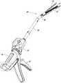
- FIG. 1is a schematic structural view of a medical stapler according to an embodiment of the present invention.
- FIG. 2is a top plan view of a staple cartridge assembly in accordance with an embodiment of the present invention.
- FIG. 3is a schematic view showing a partial exploded structure of a staple cartridge assembly according to an embodiment of the present invention
- FIG. 4is a schematic structural view showing the staple cartridge assembly in an initial state according to an embodiment of the present invention.
- FIG. 5is a schematic structural view of a spring piece when the staple cartridge assembly is in an initial state according to an embodiment of the present invention
- FIG. 6is a schematic structural view of a firing process of a staple cartridge assembly according to an embodiment of the present invention.
- FIG. 7is a schematic structural view showing completion of firing of a staple cartridge assembly according to an embodiment of the present invention.
- FIG. 8is a schematic view showing the structure of the elastic piece when the nail cartridge assembly is in the completion of firing according to an embodiment of the present invention.
- the medical stapler of the present inventionis specifically explained by taking a laparoscopic surgical cutting stapler as an example, but it should be noted that the technical spirit involved in the following embodiments may be alternatively utilized. Go to other forms of stapler.
- the medical stapleris used to apply a plurality of staples to the physiological tissue of the human body while correspondingly cutting the physiological tissue.
- the medical staplerincludes an instrument body 10, a coil 20 coupled to the instrument body 10, and a firing handle 30 pivotally coupled to the instrument body 10.
- the distal end of the instrument body 10is further provided with a staple cartridge assembly 40, which includes a staple cartridge 41, an anvil 42, a cartridge holder 43, a staple cartridge connector 44, an I-shaped cutter 45, and a nail
- a staple cartridge assembly 40which includes a staple cartridge 41, an anvil 42, a cartridge holder 43, a staple cartridge connector 44, an I-shaped cutter 45, and a nail
- the joint 46 at the distal end of the cartridge connector 44by controlling the direction of rotation and the angle of rotation of the joint 46, allows the region defined by the staple cartridge 41 and the anvil 42 to rotate relative to the cartridge attachment member 44 to accommodate multi-angle anastomosis procedures.
- the cartridge holder 43defines a support channel for mounting the staple cartridge 41 therein, the cartridge holder 43 for attaching the staple cartridge 41 to the staple cartridge connector 44.
- the staple cartridge 41 and the anvil 42are arranged to be relatively rotatable, and when the two are rotated to the open state, the operated target physiological tissue can be placed between the two, and then, The two are rotated to a closed state, and the target physiological tissue between the two is clamped for subsequent cutting and stitching operations.
- the proximal anvil of the anvil 42is subjected to an external force to keep the anvil 42 and the staple cartridge 41 open.
- the knife 45is located near the cartridge assembly 40 end.
- the medical stapler/spin assembly 40When the medical stapler/spin assembly 40 is in the closed state, driven by the I-knife 45, the anvil 42 and the staple cartridge 41 are closed, during which the target physiological tissue can be clamped, the I-knife 45 Relative to the initial state, the distal end of the medical stapler/snap cartridge assembly 40 is moved a distance, but is still generally located at the proximal end of the cartridge assembly 40.
- the anvil 42 and staple cartridge 41remain closed, and the I-knife 45 is moved distally from the proximal end of the cartridge assembly 40.
- the clamped physiological tissueis cut and can be stopped at the distal end of the cartridge assembly 40 to stop moving.
- the cartridge holder 43includes a first abutment surface 432 remote from the anvil 42 and mating with one end 451 of the I-knife 45; the anvil 42 includes a face opposite the anvil surface and A second abutting surface that cooperates with the other end 452 of the I-knife 45.
- the magazines 41, 421, and 431 that match the I-knife 45are formed in the staple cartridge 41, the anvil 42, and the cartridge holder 43.
- the cutter grooves 411, 421, 431extend from the proximal end of the staple cartridge 41, the anvil 42, and the cartridge holder 43 to the distal end thereof, respectively.
- the knife pockets 411, 421, 431can be cooperatively formed to allow the I-knife 45 to be oriented from the proximal end of the cartridge assembly 40 toward the distal end. Or a channel whose distal end moves toward the proximal direction.
- the cartridge assembly 40further includes a pusher bar 47 coupled to the proximal end of the I-knife 45, the pusher bar 47 driving the I-knife 45 from the paddles 411, 421, 431
- the proximal endis moved distally, or the distal end is moved proximally.
- the cutting grooves 411, 421, 431provide a moving path to the I-knife 45 and the push-rod bar 47 during the process and simultaneously guide the same, and the regions defined by the anvil 42 and the staple cartridge 41 are rotated relative to the staple cartridge connecting member 44.
- the pusher bar 47is also bent at a certain angle so that the I-knife 45 can smoothly move toward the distal end of the medical stapler.
- the cartridge assembly 40further includes a elastic piece 50 , and the elastic piece 50 is provided with a first through groove 55; as shown in FIG. 3 , the push tool bar 47 is composed of a plurality of slices; As shown in FIG. 4 and FIG. 5, when the cartridge assembly 40 is in an initial state and a closed state, the pusher bar 47 is partially located in the first through slot 55, and the first through slot 55 is in the The plurality of sheets are superimposed to limit the plurality of sheets from being separated from each other; as shown in FIG. 6, during the firing of the cartridge assembly 40, the pusher bar 47 is moved toward the distal end of the cartridge assembly 40 to be squeezed.
- the elastic piece 50is deformed, and the pusher bar 47 is gradually separated from the first through groove 55; as shown in FIG. 7, when the nail cartridge assembly 40 is fired, the I-shaped blade 45 is The distal end of the cartridge assembly 40 is stopped by a limit, and the pusher bar 47 is completely disengaged from the first through slot 55.
- the width of the first through groove 55 in the stacking direction of the plurality of sheetsis equal to or slightly larger than the thickness of the plurality of sheets, so that the first through groove 55 can be better.
- Multi-sheet stacking directionThe plurality of sheets constituting the pusher bar 47 are restricted from being separated from each other.
- the elastic piece 50includes a first end 51 and a second end 52 connected to the staple cartridge connecting member 44, and the first end 51 is located in the first At the distal end of the two ends 52, at least one of the first end 51 and the second end 52 is movably coupled to the staple cartridge connector 44.
- the first end 51is movably connected to the cartridge connector 44 and the second end 52 is fixedly coupled to the cartridge connector 44.
- the first end 51is oriented. The distal end of the cartridge assembly 40 is moved, but not limited thereto.
- the second end 52is movably coupled to the cartridge connector 44 and the first end 51 is fixedly coupled to the cartridge connector 44.
- the second end 52moves toward the proximal end of the cartridge assembly 40 during firing of the cartridge assembly 40; in another example, the first end 51 and the second end 52 are both The staple cartridge connector 44 is movably coupled, the first end 51 moving toward the distal end of the cartridge assembly 40 during firing of the cartridge assembly 40 while the second end 52 is toward the cartridge assembly 40 Moved proximally.
- the first end 51is movably connected to the staple cartridge connecting member 44, and the first end 51 is disposed between the distal end of the first through slot 55.
- There is a second through slot 56and the second through slot 56 is connected to the cartridge connecting member 44 through the limiting member 53, and the limiting member 53 and the cartridge connecting member 44 are fixed to each other when the cartridge assembly 40 is in an initial state.
- the second through slot 56is relatively stationary with the limiting member 53; during the firing of the cartridge assembly 40, the limiting member 53 can be in the second through slot 56.
- the inner through slot 56moves relative to the stop member 53 toward the distal end of the cartridge assembly 40.
- the limiting member 53can be a limiting nail 53.
- the maximum diameter of the top cover of the limiting nail 53is greater than the width of the second through groove 56 in the direction in which the plurality of sheets are stacked to prevent the second through groove 56 from being released from the limiting nail. 53.
- the second end 52is fixedly coupled to the staple cartridge connector 44.
- the pusher bar 47includes a pusher bar body 473 and a trailing end 474, and the tail end 474 is located at the pusher blade. a proximal end of the rod body 473, and a tail end 474 protruding from the pusher bar body 473 toward the second end 52.
- the proximal end of the first through slot 55 and the second end 52are The abutting portion 57 presses the elastic piece 50 when the tail end 474 and the abutting portion 57 interfere with each other, so that the elastic piece 50 is deformed.
- the first through groove 55 and the second through groove 56penetrate the elastic piece 50 in the thickness direction of the elastic piece 50 , and the abutting portion 57 does not penetrate the elastic piece 50 , and the abutting portion 57 It is essentially a part of the shrapnel 50.
- the proximal end of the pusher bar 47is coupled to the firing bar 70 by a transmission block 60 that controls the pusher bar 47 to move toward the distal and proximal ends of the cartridge assembly 40.
- the cartridge unit 40is horizontally placed and the magazine 41 is located below the anvil 42 as an example.
- the description of the positionis based on the above description.
- the area of the lower portion of the staple cartridge connecting member 44is the area of the lower portion of the staple cartridge connecting member 44, but not limited thereto.
- the elastic piece 50can be disposed in other areas.
- the pusher bar 47includes a first end face 471 formed by superposing the plurality of sheets and a second end face 472 facing away from the first end face 471.
- the distance between the highest point 54 of the elastic piece 50 and the first end surface 471is greater than the highest point 54 and the The distance of the second end face 472, preferably, the highest point 54 is higher than the second end face 472.
- the tail end 474 of the pusher bar 47is away from the abutting portion 57 of the elastic piece 50, the second through groove 56 is relatively stationary with the limiting member 53, and the pushing bar 47 is partially located at the first In the through groove 55, the first through groove 55 restricts the plurality of sheets from being separated from each other in the stacking direction of the plurality of sheets.
- the highest point 54gradually moves away from the second end surface 472 and gradually approaches the first end surface 471.
- the trailing end 474 of the pusher bar 47gradually approaches and presses the abutment portion 57, and the elastic piece 50 deforms.
- the second through slot 56moves relative to the limiting member 53 toward the distal end of the cartridge assembly 40.
- the pusher bar 47is still partially located in the first through slot 55, and the first through slot 55
- the plurality of sheetsare restricted from being separated from each other in the stacking direction of the plurality of sheets.
- the spring piece 50is separated from the pusher bar 47 when the staple cartridge assembly 40 is fired.
- the tail end 474 of the pusher bar 47is away from the abutting portion 57 of the elastic piece 50.
- the second through groove 56is relatively stationary with the limiting member 53.
- the elastic piece 50is located at the pusher bar 47 and the transmission block. 60 and below the firing bar 70, such that the pusher bar 47, the transmission block 60, and the firing bar 70 can move over the shrapnel 50 as the pusher bar 47 moves toward the proximal end of the cartridge assembly 40. As shown in FIG.
- the elastic piece 50is disposed at an intermediate position close to the length from the proximal end to the distal end of the staple cartridge connecting member 44, where the plurality of thin slices are most likely to be mutually inclined when the corresponding pushing rod 47 is bent at a corresponding angle. Separated location.
- the pusher bar 47when the region defined by the anvil 42 and the staple cartridge 41 is rotated by a certain angle with respect to the staple cartridge connecting member 44, the pusher bar 47 also needs to be bent at a corresponding angle, and the distal end of the pusher bar 47 is clamped at the first end.
- the inner end of the pusher bar 47is clamped in the first through groove 55, and the pusher bar 47 pushes the I-knife 45 forward, due to the first through groove 55.
- the restricting action of the proximal end of the pusher bar 47causes the plurality of sheets forming the pusher bar 47 not to be separated from each other, so that the pusher bar 47 can stably advance the I-knife 45.
- the present inventionlimits the plurality of sheets through the first through groove 55 on the elastic piece 50, so that the plurality of sheets The plurality of sheets are not separated from each other in the stacking direction, and the deformation of the elastic piece 50 allows the pusher bar 47 to smoothly move toward the distal end or the proximal end of the cartridge assembly 40, preventing the elastic piece 50 from blocking the pusher bar. 47 moves.
Landscapes
- Health & Medical Sciences (AREA)
- Life Sciences & Earth Sciences (AREA)
- Surgery (AREA)
- Heart & Thoracic Surgery (AREA)
- Engineering & Computer Science (AREA)
- Biomedical Technology (AREA)
- Nuclear Medicine, Radiotherapy & Molecular Imaging (AREA)
- Medical Informatics (AREA)
- Molecular Biology (AREA)
- Animal Behavior & Ethology (AREA)
- General Health & Medical Sciences (AREA)
- Public Health (AREA)
- Veterinary Medicine (AREA)
- Surgical Instruments (AREA)
Abstract
Description
Translated fromChinese本申请要求了申请日为2014年12月30日,申请号为201410841670.6,发明名称为“钉仓组件及使用该钉仓组件的医用吻合器”的中国专利申请的优先权,其全部内容通过引用结合在本申请中。The present application claims priority to Chinese Patent Application No. 201410841670.6, filed on Dec. 30, 2014, entitled "Staple cartridge assembly and medical stapler using the cartridge assembly", the entire contents of which are incorporated by reference. Combined in this application.
本发明属于医疗器械领域,具体涉及一种钉仓组件及使用该钉仓组件的医用吻合器。The invention belongs to the field of medical instruments, and in particular relates to a staple cartridge assembly and a medical stapler using the same.
医用吻合器是对肠道等生理组织进行外科手术时经常使用的一种医疗器械,它是医学上使用的替代传统手工缝合的设备,由于现代科技的发展和制作技术的改进,目前临床上使用的医用吻合器质量可靠,使用方便,严密、松紧合适,尤其是其缝合快速、操作简便及很少有副作用和手术并发症等优点,有时还使得过去无法切除的肿瘤手术得以病灶切除,很受国内外临床外科医生的青睐和推崇。该仪器性能的差异对于整个手术效果起着至关重要的作用。The medical stapler is a medical device that is often used in the surgical operation of the intestines and other physiological tissues. It is a medical alternative to the traditional manual suture device. Due to the development of modern technology and the improvement of the production technology, it is currently used clinically. The medical stapler is reliable in quality, easy to use, and suitable for tightness and tightness, especially its quick suturing, easy operation, few side effects and surgical complications, and sometimes the tumor surgery that could not be removed in the past can be removed by the lesion. The favor and respect of clinical surgeons at home and abroad. The difference in performance of the instrument plays a crucial role in the overall surgical outcome.
目前,医用吻合器的推刀杆可由多片较薄的薄片组成,每片薄片的厚度约为0.25mm,由于薄片较薄且具有弹性,因此,由多片薄片组成的推刀杆在外力作用下可弯曲形变。实际运用中,医用吻合器击发过程中及推刀杆弯曲时,多片薄片受到极大的外力作用,使得多片薄片于多片薄片叠加方向上易形变或相互分离,从而导致医用吻合器击发不到位。At present, the pusher bar of the medical stapler can be composed of a plurality of thin slices, each of which has a thickness of about 0.25 mm. Since the slice is thin and elastic, the pusher bar composed of a plurality of slices acts externally. The bottom can be bent and deformed. In practical application, when the medical stapler is fired and the pusher bar is bent, the plurality of slices are subjected to a great external force, so that the plurality of slices are easily deformed or separated from each other in the stacking direction of the plurality of slices, thereby causing the medical stapler to be fired. Did not do well.
发明内容Summary of the invention
本发明的目的在于提供一种钉仓组件及使用该钉仓组件的医用吻合器。It is an object of the present invention to provide a staple cartridge assembly and a medical stapler using the same.
为实现上述发明目的之一,本发明一实施方式提供一种钉仓组件,包括钉仓连接件及推刀杆,所述钉仓组件还包括弹片,所述弹片上设有第一贯穿槽;所述推刀杆由多片薄片叠加组成;其中,当所述钉仓组件处于初始状态及闭合状态时,所述推刀杆部分位于所述第一贯穿槽内,所述第一贯穿槽于所述多片薄片叠加方向上限制所述多片薄片相互分离;在所述钉仓组件的击发过程中,所述推刀杆朝向所述钉仓组件远端移动而挤压所述弹片,所述弹片发生形变,所述推刀杆逐渐脱离所述第一贯穿槽;当所述钉仓组件击发完成时,所述推刀杆脱离所述第一贯穿槽。In order to achieve the above object, an embodiment of the present invention provides a staple cartridge assembly, comprising a staple cartridge connector and a pusher bar, the cartridge assembly further comprising a spring piece, wherein the elastic piece is provided with a first through groove; The pusher bar is composed of a plurality of sheets stacked; wherein, when the cartridge assembly is in an initial state and a closed state, the pusher bar portion is located in the first through slot, and the first through slot is The plurality of sheets are superimposed to restrict the plurality of sheets from being separated from each other; during the firing of the cartridge assembly, the pusher rod is moved toward the distal end of the cartridge assembly to press the elastic piece. Deformation of the shrapnel, the pusher bar gradually disengages from the first through slot; when the staple cartridge assembly is fired, the pusher bar is disengaged from the first through slot.
作为本发明一实施方式的进一步改进,所述推刀杆包括由所述多片薄片叠加形成的第一端面及与所述第一端面相背离的第二端面,当所述钉仓组件处于初始状态及闭合状态时,所述弹片的最高点与所述第一端面的距离大于所述最高点与所述第二端面的距离;在所述钉仓组件的击发过程中,所述最高点逐渐远离所述第二端面并逐渐靠近所述第一端面;当所述钉仓组件击发完成时,所述弹片与所述推刀杆相分离。According to a further improvement of an embodiment of the present invention, the pusher bar includes a first end surface formed by superposing the plurality of sheets and a second end surface facing away from the first end surface, when the cartridge assembly is initially a state and a closed state, a distance between a highest point of the elastic piece and the first end surface is greater than a distance between the highest point and the second end surface;During the firing of the assembly, the highest point gradually moves away from the second end surface and gradually approaches the first end surface; when the staple cartridge assembly is fired, the spring piece is separated from the pusher bar.
作为本发明一实施方式的进一步改进,所述弹片包括与所述钉仓连接件活动连接的第一端及第二端,所述第一端位于所述第二端的远端,在所述钉仓组件的击发过程中,所述第一端朝向所述钉仓组件的远端移动,同时所述第二端朝向所述钉仓组件的近端移动。As a further improvement of an embodiment of the present invention, the elastic piece includes a first end and a second end movably coupled to the staple cartridge connector, the first end being located at a distal end of the second end, at the staple During firing of the cartridge assembly, the first end moves toward the distal end of the cartridge assembly while the second end moves toward the proximal end of the cartridge assembly.
作为本发明一实施方式的进一步改进,所述弹片包括与所述钉仓连接件活动连接的第一端及与所述钉仓连接件固定连接的第二端,所述第一端位于所述第二端的远端,在所述钉仓组件的击发过程中,所述第一端朝向所述钉仓组件的远端移动。In a further improvement of an embodiment of the present invention, the elastic piece includes a first end movably coupled to the staple cartridge connector and a second end fixedly coupled to the staple cartridge connector, the first end being located at the The distal end of the second end moves the distal end toward the distal end of the cartridge assembly during firing of the cartridge assembly.
作为本发明一实施方式的进一步改进,所述钉仓组件还包括限位件,所述第一端与所述第一贯穿槽之间设有第二贯穿槽,所述第二贯穿槽通过所述限位件与所述钉仓连接件活动连接,当所述钉仓组件处于初始状态及闭合状态时,所述第二贯穿槽与所述限位件相对静止;在所述钉仓组件的击发过程中,所述限位件可在所述第二贯穿槽内滑动,所述第二贯穿槽相对所述限位件朝向所述钉仓组件的远端移动。As a further improvement of an embodiment of the present invention, the cartridge assembly further includes a limiting member, a second through slot is disposed between the first end and the first through slot, and the second through slot passes through the The limiting member is movably connected to the staple cartridge connecting member, and the second through slot is relatively stationary with the limiting member when the cartridge assembly is in an initial state and a closed state; at the cartridge assembly During the firing, the limiting member is slidable within the second through slot, and the second through slot moves relative to the limiting member toward the distal end of the cartridge assembly.
作为本发明一实施方式的进一步改进,所述限位件为限位钉,所述限位钉与所述钉仓连接件固定连接。As a further improvement of an embodiment of the present invention, the limiting member is a limiting nail, and the limiting nail is fixedly connected to the staple cartridge connecting member.
作为本发明一实施方式的进一步改进,所述推刀杆包括推刀杆本体及尾端,所述尾端位于所述推刀杆本体的近端,所述第一贯穿槽的近端与所述第二端之间为抵持部,当所述推刀杆朝向所述钉仓组件远端移动时,所述尾端挤压所述抵持部以使得所述弹片形变。According to a further improvement of an embodiment of the present invention, the pusher bar includes a pusher bar body and a tail end, the tail end is located at a proximal end of the pusher bar body, and the proximal end of the first through slot is Between the second ends is a resisting portion that presses the abutting portion to deform the elastic piece when the pusher bar moves toward the distal end of the cartridge assembly.
作为本发明一实施方式的进一步改进,所述弹片位于所述钉仓连接件的近端至近端长度的中间位置。As a further improvement of an embodiment of the invention, the elastic piece is located intermediate the length of the proximal end to the proximal end of the staple cartridge connector.
为实现上述发明目的之一,本发明一实施方式提供一种医用吻合器,所述医用吻合器包括如上所述的钉仓组件。To achieve one of the above objects, an embodiment of the present invention provides a medical stapler comprising the cartridge assembly as described above.
作为本发明一实施方式的进一步改进,所述医用吻合器还包括击发杆,当所述医用吻合器处于击发完成时,所述击发杆抵接所述弹片。As a further improvement of an embodiment of the present invention, the medical stapler further includes a firing rod that abuts the elastic piece when the medical stapler is in the completion of firing.
与现有技术相比,本发明的有益效果在于:本发明通过弹片上的第一贯穿槽对多片薄片进行限位,使得多片薄片于所述多片薄片叠加方向上相互不分离,且通过弹片的形变,使得推刀杆可以顺利地朝向所述医用吻合器的远端或近端移动,避免弹片阻挡推刀杆的移动。Compared with the prior art, the present invention has the beneficial effects that the present invention limits the plurality of sheets by the first through grooves on the elastic sheets, so that the plurality of sheets are not separated from each other in the stacking direction of the plurality of sheets, and By the deformation of the elastic piece, the pusher bar can be smoothly moved toward the distal end or the proximal end of the medical stapler to prevent the elastic piece from blocking the movement of the pusher bar.
图1是本发明一实施方式的医用吻合器结构示意图;1 is a schematic structural view of a medical stapler according to an embodiment of the present invention;
图2是本发明一实施方式中钉仓组件俯视图;2 is a top plan view of a staple cartridge assembly in accordance with an embodiment of the present invention;
图3是本发明一实施方式中钉仓组件部分爆炸结构示意图;3 is a schematic view showing a partial exploded structure of a staple cartridge assembly according to an embodiment of the present invention;
图4是本发明一实施方式中钉仓组件处于初始状态的结构示意图;4 is a schematic structural view showing the staple cartridge assembly in an initial state according to an embodiment of the present invention;
图5是本发明一实施方式中钉仓组件处于初始状态时的弹片结构示意图;5 is a schematic structural view of a spring piece when the staple cartridge assembly is in an initial state according to an embodiment of the present invention;
图6是本发明一实施方式中钉仓组件击发过程的结构示意图;6 is a schematic structural view of a firing process of a staple cartridge assembly according to an embodiment of the present invention;
图7是本发明一实施方式中钉仓组件击发完成的结构示意图;7 is a schematic structural view showing completion of firing of a staple cartridge assembly according to an embodiment of the present invention;
图8是本发明一实施方式中钉仓组件处于击发完成时的弹片结构示意图。FIG. 8 is a schematic view showing the structure of the elastic piece when the nail cartridge assembly is in the completion of firing according to an embodiment of the present invention.
以下将结合附图所示的具体实施方式对本发明进行详细描述。但这些实施方式并不限制本发明,本领域的普通技术人员根据这些实施方式所做出的结构、方法、或功能上的变换均包含在本发明的保护范围内。The invention will be described in detail below in conjunction with the specific embodiments shown in the drawings. However, the embodiments are not intended to limit the invention, and the structural, method, or functional changes made by those skilled in the art in accordance with the embodiments are included in the scope of the present invention.
本发明内所描述的表达位置与方向的词,均是以器械操作者作为参照,靠近操作者的一端为近端,远离操作者的一端为远端。The words expressing position and orientation described in the present invention are referenced by the operator of the device, with one end near the operator being the proximal end and one end remote from the operator being the distal end.
在本发明的实施方式中,以腔镜外科切割吻合器为示例对本发明的医用吻合器做具体的阐释,但应当说明的是,在下述的实施方式中所涉及的技艺精神可以被替换地利用到其它形式的吻合器上。In the embodiment of the present invention, the medical stapler of the present invention is specifically explained by taking a laparoscopic surgical cutting stapler as an example, but it should be noted that the technical spirit involved in the following embodiments may be alternatively utilized. Go to other forms of stapler.
如图1-图3所示,医用吻合器用于将多个缝合钉施加到人体的生理组织上,同时相应的对生理组织实施切割。所述医用吻合器包括器械本体10、与器械本体10配接的旋圈20,以及枢轴连接所述器械本体10的击发把手30。As shown in Figures 1-3, the medical stapler is used to apply a plurality of staples to the physiological tissue of the human body while correspondingly cutting the physiological tissue. The medical stapler includes an
所述器械本体10的远端还设有钉仓组件40,所述钉仓组件40包括钉仓41、钉砧42、钉仓架43、钉仓连接件44、工字刀45以及设置于钉仓连接件44远端的关节46,通过控制关节46的转动方向及转动角度,可使得钉仓41及钉砧42所限定区域相对钉仓连接件44转动,以适应多角度切割吻合手术。The distal end of the
所述钉仓架43限定了一支撑通道,以将钉仓41可安装地容纳在其中,所述钉仓架43用于将所述钉仓41连接至所述钉仓连接件44。The
在本实施方式中,钉仓41和钉砧42被设置为可以相对地转动,当两者转动至打开状态时,被操作的目标生理组织可被置放于两者之间,随后,通过将两者转动至闭合状态,位于两者之间的目标生理组织被夹紧,以进行后续的切割及缝合操作。In the present embodiment, the
当所述医用吻合器/钉仓组件40处于初始状态时,所述钉砧42的近端的钉砧尾受到外力作用,以保持所述钉砧42和钉仓41呈打开状,所述工字刀45位于所述钉仓组件40的近端。When the medical stapler/
当所述医用吻合器/钉仓组件40处于闭合状态时,受所述工字刀45驱动,所述钉砧42和钉仓41闭合,其间可夹紧目标生理组织,所述工字刀45相对于所述初始状态而言,向所述医用吻合器/钉仓组件40的远端移动了一定距离,但总体而言仍然位于所述钉仓组件40的近端。When the medical stapler/
当所述医用吻合器/钉仓组件40处于击发状态时,所述钉砧42和钉仓41仍然保持闭合,所述工字刀45由所述钉仓组件40的近端向远端移动,切割夹紧的生理组织,并可在所述钉仓组件40的远端受到限位停止移动。When the medical stapler/
如图3所示,所述钉仓架43包括远离所述钉砧42且与所述工字刀45的一端451配合的第一抵触面432;所述钉砧42包括与钉砧面相背且与所述工字刀45的另一端452配合的第二抵触面。As shown in FIG. 3, the
钉仓41、钉砧42、钉仓架43上形成有配合所述工字刀45的走刀槽411、421、431。所述走刀槽411、421、431分别从所述钉仓41、钉砧42、钉仓架43的近端向其远端延伸。当所述钉仓41和所述钉砧42闭合后,所述走刀槽411、421、431可配合形成允许所述工字刀45由所述钉仓组件40的近端朝向远端方向,或远端朝向近端方向移动的通道。The
所述钉仓组件40还包括连接于所述工字刀45近端的推刀杆47,所述推刀杆47可驱动所述工字刀45由所述走刀槽411、421、431的近端向远端,或远端向近端移动。走刀槽411、421、431在此过程中对工字刀45及推刀杆47提供运动路径且同时对其进行导向,当钉砧42及钉仓41所限定区域相对钉仓连接件44转动一定角度时,推刀杆47也随之弯曲一定的角度,以使得工字刀45可以顺利地朝向医用吻合器的远端移动。The
如图4至图8所示,钉仓组件40还包括弹片50,所述弹片50上设有第一贯穿槽55;如图3所示,所述推刀杆47由多片薄片组成;其中,如图4及图5所示,当钉仓组件40处于初始状态及闭合状态时,所述推刀杆47部分位于所述第一贯穿槽55内,所述第一贯穿槽55于所述多片薄片叠加方向上限制所述多片薄片相互分离;如图6所示,在钉仓组件40的击发过程中,所述推刀杆47朝向所述钉仓组件40远端移动而挤压所述弹片50,所述弹片50发生形变,所述推刀杆47逐渐脱离所述第一贯穿槽55;如图7所示,当钉仓组件40击发完成后,所述工字刀45在所述钉仓组件40的远端受到限位停止,所述推刀杆47完全脱离所述第一贯穿槽55。As shown in FIG. 4 to FIG. 8 , the
在本实施方式中,所述第一贯穿槽55于所述多片薄片叠加方向上的宽度等于或略大于所述多片薄片叠加的厚度,从而使得第一贯穿槽55可以更好地于所述多片薄片叠加方向上限制组成推刀杆47的多片薄片相互分离。In this embodiment, the width of the first through
在本实施方式中,如图4及图5所示,所述弹片50包括与所述钉仓连接件44连接的第一端51及第二端52,所述第一端51位于所述第二端52的远端,所述第一端51及所述第二端52的至少其中之一与所述钉仓连接件44活动连接。本实施方式中以第一端51与钉仓连接件44活动连接且第二端52与钉仓连接件44固定连接为例,在钉仓组件40的击发过程中,所述第一端51朝向所述钉仓组件40的远端移动,但不以此为限,在一示例中,所述第二端52与钉仓连接件44活动连接且第一端51与钉仓连接件44固定连接,在钉仓组件40的击发过程中,所述第二端52朝向所述钉仓组件40的近端移动;在另一示例中,所述第一端51及所述第二端52均与钉仓连接件44活动连接,在钉仓组件40击发过程中,所述第一端51朝向所述钉仓组件40的远端移动,同时所述第二端52朝向所述钉仓组件40的近端移动。In the present embodiment, as shown in FIG. 4 and FIG. 5, the
在本实施方式中,如图4及图5所示,所述第一端51与钉仓连接件44活动连接,所述第一端51与所述第一贯穿槽55的远端之间设有第二贯穿槽56,所述第二贯穿槽56通过限位件53与所述钉仓连接件44连接,限位件53与钉仓连接件44相互固定,当钉仓组件40为初始状态、闭合状态及击发完成时,所述第二贯穿槽56与所述限位件53相对静止;在钉仓组件40的击发过程中,所述限位件53可在所述第二贯穿槽56内滑动,所述第二贯穿槽56相对所述限位件53朝向所述钉仓组件40的远端移动。所述限位件53可为限位钉53,限位钉53的顶盖的最大直径大于第二贯穿槽56于多片薄片叠加方向上的宽度,以防止第二贯穿槽56脱离限位钉53。In the present embodiment, as shown in FIG. 4 and FIG. 5, the
在本实施方式中,所述第二端52与所述钉仓连接件44固定连接,所述推刀杆47包括推刀杆本体473及尾端474,所述尾端474位于所述推刀杆本体473的近端,且尾端474朝向所述第二端52方向凸伸出所述推刀杆本体473,所述第一贯穿槽55的近端与所述第二端52之间为抵持部57,当所述尾端474与所述抵持部57相互干涉时,所述尾端474挤压所述弹片50,使得所述弹片50形变。In the present embodiment, the
在本实施方式中,所述第一贯穿槽55及第二贯穿槽56均于弹片50的厚度方向上贯穿所述弹片50,所述抵持部57不贯穿弹片50,所述抵持部57实质为弹片50的一部分。In the present embodiment, the first through
在本实施方式中,所述推刀杆47的近端通过传动块60与击发杆70连接,击发杆70控制所述推刀杆47朝向所述钉仓组件40的远端及近端移动。In the present embodiment, the proximal end of the
本实施方式的钉仓组件40的具体工作流程如下:The specific workflow of the
在本实施方式中,以钉仓组件40水平放置且钉仓41位于钉砧42下方为例,其他的方位性描述语均以上述说明为依据。另外,本实施方式以弹片50设置于钉仓连接件44的下方区域为例,钉仓连接件44的下方区域为邻近钉仓41的区域,但不以此为限,在其他实施方式中,弹片50可以设置于其他区域。所述推刀杆47包括由所述多片薄片叠加形成的第一端面471及与所述第一端面471相背离的第二端面472。In the present embodiment, the
如图4及图5所示,当所述钉仓组件40处于初始状态及闭合状态时,所述弹片50的最高点54与所述第一端面471的距离大于所述最高点54与所述第二端面472的距离,较佳的,所述最高点54高于所述第二端面472。所述推刀杆47的尾端474远离所述弹片50的抵持部57,所述第二贯穿槽56与所述限位件53相对静止,所述推刀杆47部分位于所述第一贯穿槽55内,第一贯穿槽55于所述多片薄片叠加方向上限制所述多片薄片相互分离。As shown in FIG. 4 and FIG. 5, when the
如图6所示,在钉仓组件40的击发过程中,所述最高点54逐渐远离所述第二端面472并逐渐靠近所述第一端面471。当所述推刀杆47朝向所述钉仓组件40的远端移动时,所述推刀杆47的尾端474逐渐靠近并挤压所述抵持部57,所述弹片50形变,所述第二贯穿槽56相对所述限位件53朝向所述钉仓组件40的远端移动,此时,所述推刀杆47仍然部分位于所述第一贯穿槽55内,第一贯穿槽55于所述多片薄片叠加方向上限制所述多片薄片相互分离。当最高点54逐渐下降至邻近所述第一端面471时,所述推刀杆47的尾端474逐渐脱离所述抵持部57,击发杆70逐渐抵接弹片50,此时,推刀杆47、传动块60及击发杆70均可于所述弹片50的上方移动,推刀杆47、传动块60及击发杆70可于弹片50上方继续挤压弹片50,直至推刀杆47到达钉仓组件40的最远端。As shown in FIG. 6, during firing of the
如图7及图8所示,在钉仓组件40击发完成时,所述弹片50与所述推刀杆47相分离。所述推刀杆47的尾端474远离所述弹片50的抵持部57,所述第二贯穿槽56与所述限位件53相对静止,所述弹片50位于推刀杆47、传动块60及击发杆70下方,以便于当所述推刀杆47朝向钉仓组件40近端移动时,所述推刀杆47、传动块60及击发杆70均可于所述弹片50上方移动。如图4所示,所述弹片50设置于接近所述钉仓连接件44近端至远端长度的中间位置处,此处是推刀杆47在弯曲相应的角度时多片薄片最易相互分离的位置。As shown in FIGS. 7 and 8, the
在本实施方式中,当钉砧42及钉仓41所限定区域相对钉仓连接件44转动一定角度时,推刀杆47也需弯曲相应的角度,推刀杆47的远端夹持于第一走刀槽411及第二走刀槽421内,推刀杆47的近端夹持于第一贯穿槽55内,当推刀杆47推动工字刀45前进时,由于第一贯穿槽55对推刀杆47近端的限制作用,形成推刀杆47的多片薄片相互不分离,使得推刀杆47可以稳定的推动工字刀45前进。In the present embodiment, when the region defined by the
综上所述,本发明通过弹片50上的第一贯穿槽55对多片薄片进行限位,使得多片薄片于所述多片薄片叠加方向上相互不分离,且通过弹片50的形变,使得推刀杆47可以顺利地朝向所述钉仓组件40的远端或近端移动,避免弹片50阻挡推刀杆47的移动。In summary, the present invention limits the plurality of sheets through the first through
应当理解,虽然本说明书按照实施方式加以描述,但并非每个实施方式仅包含一个独立的技术方案,说明书的这种叙述方式仅仅是为清楚起见,本领域技术人员应当将说明书作为一个整体,各实施方式中的技术方案也可以经适当组合,形成本领域技术人员可以理解的其他实施方式。It should be understood that, although the description is described in terms of embodiments, the embodiments are not intended to be construed as a single. The technical solutions in the embodiments may also be combined as appropriate to form other embodiments that can be understood by those skilled in the art.
上文所列出的一系列的详细说明仅仅是针对本发明的可行性实施方式的具体说明,它们并非用以限制本发明的保护范围,凡未脱离本发明技艺精神所作的等效实施方式或变更均应包含在本发明的保护范围之内。The series of detailed descriptions set forth above are merely illustrative of the possible embodiments of the present invention, and are not intended to limit the scope of the present invention. Changes are intended to be included within the scope of the invention.
Claims (10)
Translated fromChinesePriority Applications (5)
| Application Number | Priority Date | Filing Date | Title |
|---|---|---|---|
| US15/540,959US10772628B2 (en) | 2014-12-30 | 2015-12-22 | Staple cartridge assembly and medical stapler using the staple cartridge assembly |
| BR112017013859-0ABR112017013859B1 (en) | 2014-12-30 | 2015-12-22 | Staple cartridge assembly and medical stapler using the staple cartridge assembly |
| EP15875127.1AEP3241503B8 (en) | 2014-12-30 | 2015-12-22 | Staple cartridge assembly and medical anastomat using same |
| ES15875127TES2821738T3 (en) | 2014-12-30 | 2015-12-22 | Staple cartridge assembly and medical anastomat using the same |
| JP2017531738AJP6389007B2 (en) | 2014-12-30 | 2015-12-22 | Staple cartridge unit and medical stapler using the staple cartridge unit |
Applications Claiming Priority (2)
| Application Number | Priority Date | Filing Date | Title |
|---|---|---|---|
| CN201410841670.6ACN104434250B (en) | 2014-12-30 | 2014-12-30 | Reload unit and medical stapler using same |
| CN201410841670.6 | 2014-12-30 |
Publications (1)
| Publication Number | Publication Date |
|---|---|
| WO2016107449A1true WO2016107449A1 (en) | 2016-07-07 |
Family
ID=52881545
Family Applications (1)
| Application Number | Title | Priority Date | Filing Date |
|---|---|---|---|
| PCT/CN2015/098180WO2016107449A1 (en) | 2014-12-30 | 2015-12-22 | Staple cartridge assembly and medical anastomat using same |
Country Status (7)
| Country | Link |
|---|---|
| US (1) | US10772628B2 (en) |
| EP (1) | EP3241503B8 (en) |
| JP (1) | JP6389007B2 (en) |
| CN (1) | CN104434250B (en) |
| BR (1) | BR112017013859B1 (en) |
| ES (1) | ES2821738T3 (en) |
| WO (1) | WO2016107449A1 (en) |
Cited By (3)
| Publication number | Priority date | Publication date | Assignee | Title |
|---|---|---|---|---|
| CN112438764A (en)* | 2019-08-29 | 2021-03-05 | 苏州天臣国际医疗科技有限公司 | Closing driving mechanism and medical anastomat comprising same |
| CN112716548A (en)* | 2021-01-18 | 2021-04-30 | 苏州法兰克曼医疗器械有限公司 | Linear type cutting anastomat with turn mechanism |
| CN119423880A (en)* | 2023-08-04 | 2025-02-14 | 湖南思捷泰克医疗科技有限公司 | A segmented differential propulsion system for staplers |
Families Citing this family (321)
| Publication number | Priority date | Publication date | Assignee | Title |
|---|---|---|---|---|
| US20070084897A1 (en) | 2003-05-20 | 2007-04-19 | Shelton Frederick E Iv | Articulating surgical stapling instrument incorporating a two-piece e-beam firing mechanism |
| US9060770B2 (en) | 2003-05-20 | 2015-06-23 | Ethicon Endo-Surgery, Inc. | Robotically-driven surgical instrument with E-beam driver |
| US11998198B2 (en) | 2004-07-28 | 2024-06-04 | Cilag Gmbh International | Surgical stapling instrument incorporating a two-piece E-beam firing mechanism |
| US9072535B2 (en) | 2011-05-27 | 2015-07-07 | Ethicon Endo-Surgery, Inc. | Surgical stapling instruments with rotatable staple deployment arrangements |
| US11890012B2 (en) | 2004-07-28 | 2024-02-06 | Cilag Gmbh International | Staple cartridge comprising cartridge body and attached support |
| US8215531B2 (en) | 2004-07-28 | 2012-07-10 | Ethicon Endo-Surgery, Inc. | Surgical stapling instrument having a medical substance dispenser |
| US11484312B2 (en) | 2005-08-31 | 2022-11-01 | Cilag Gmbh International | Staple cartridge comprising a staple driver arrangement |
| US7934630B2 (en) | 2005-08-31 | 2011-05-03 | Ethicon Endo-Surgery, Inc. | Staple cartridges for forming staples having differing formed staple heights |
| US10159482B2 (en) | 2005-08-31 | 2018-12-25 | Ethicon Llc | Fastener cartridge assembly comprising a fixed anvil and different staple heights |
| US9237891B2 (en) | 2005-08-31 | 2016-01-19 | Ethicon Endo-Surgery, Inc. | Robotically-controlled surgical stapling devices that produce formed staples having different lengths |
| US11246590B2 (en) | 2005-08-31 | 2022-02-15 | Cilag Gmbh International | Staple cartridge including staple drivers having different unfired heights |
| US7669746B2 (en) | 2005-08-31 | 2010-03-02 | Ethicon Endo-Surgery, Inc. | Staple cartridges for forming staples having differing formed staple heights |
| US20070106317A1 (en) | 2005-11-09 | 2007-05-10 | Shelton Frederick E Iv | Hydraulically and electrically actuated articulation joints for surgical instruments |
| US20110295295A1 (en) | 2006-01-31 | 2011-12-01 | Ethicon Endo-Surgery, Inc. | Robotically-controlled surgical instrument having recording capabilities |
| US8820603B2 (en) | 2006-01-31 | 2014-09-02 | Ethicon Endo-Surgery, Inc. | Accessing data stored in a memory of a surgical instrument |
| US11224427B2 (en) | 2006-01-31 | 2022-01-18 | Cilag Gmbh International | Surgical stapling system including a console and retraction assembly |
| US7845537B2 (en) | 2006-01-31 | 2010-12-07 | Ethicon Endo-Surgery, Inc. | Surgical instrument having recording capabilities |
| US8186555B2 (en) | 2006-01-31 | 2012-05-29 | Ethicon Endo-Surgery, Inc. | Motor-driven surgical cutting and fastening instrument with mechanical closure system |
| US11278279B2 (en) | 2006-01-31 | 2022-03-22 | Cilag Gmbh International | Surgical instrument assembly |
| US20120292367A1 (en) | 2006-01-31 | 2012-11-22 | Ethicon Endo-Surgery, Inc. | Robotically-controlled end effector |
| US7753904B2 (en) | 2006-01-31 | 2010-07-13 | Ethicon Endo-Surgery, Inc. | Endoscopic surgical instrument with a handle that can articulate with respect to the shaft |
| US8708213B2 (en) | 2006-01-31 | 2014-04-29 | Ethicon Endo-Surgery, Inc. | Surgical instrument having a feedback system |
| US11793518B2 (en) | 2006-01-31 | 2023-10-24 | Cilag Gmbh International | Powered surgical instruments with firing system lockout arrangements |
| US8992422B2 (en) | 2006-03-23 | 2015-03-31 | Ethicon Endo-Surgery, Inc. | Robotically-controlled endoscopic accessory channel |
| US8322455B2 (en) | 2006-06-27 | 2012-12-04 | Ethicon Endo-Surgery, Inc. | Manually driven surgical cutting and fastening instrument |
| US10568652B2 (en) | 2006-09-29 | 2020-02-25 | Ethicon Llc | Surgical staples having attached drivers of different heights and stapling instruments for deploying the same |
| US11980366B2 (en) | 2006-10-03 | 2024-05-14 | Cilag Gmbh International | Surgical instrument |
| US8632535B2 (en) | 2007-01-10 | 2014-01-21 | Ethicon Endo-Surgery, Inc. | Interlock and surgical instrument including same |
| US11291441B2 (en) | 2007-01-10 | 2022-04-05 | Cilag Gmbh International | Surgical instrument with wireless communication between control unit and remote sensor |
| US8684253B2 (en) | 2007-01-10 | 2014-04-01 | Ethicon Endo-Surgery, Inc. | Surgical instrument with wireless communication between a control unit of a robotic system and remote sensor |
| US20080169333A1 (en) | 2007-01-11 | 2008-07-17 | Shelton Frederick E | Surgical stapler end effector with tapered distal end |
| US7673782B2 (en) | 2007-03-15 | 2010-03-09 | Ethicon Endo-Surgery, Inc. | Surgical stapling instrument having a releasable buttress material |
| US11564682B2 (en) | 2007-06-04 | 2023-01-31 | Cilag Gmbh International | Surgical stapler device |
| US8931682B2 (en) | 2007-06-04 | 2015-01-13 | Ethicon Endo-Surgery, Inc. | Robotically-controlled shaft based rotary drive systems for surgical instruments |
| US7753245B2 (en) | 2007-06-22 | 2010-07-13 | Ethicon Endo-Surgery, Inc. | Surgical stapling instruments |
| US11849941B2 (en) | 2007-06-29 | 2023-12-26 | Cilag Gmbh International | Staple cartridge having staple cavities extending at a transverse angle relative to a longitudinal cartridge axis |
| US8573465B2 (en) | 2008-02-14 | 2013-11-05 | Ethicon Endo-Surgery, Inc. | Robotically-controlled surgical end effector system with rotary actuated closure systems |
| US11986183B2 (en) | 2008-02-14 | 2024-05-21 | Cilag Gmbh International | Surgical cutting and fastening instrument comprising a plurality of sensors to measure an electrical parameter |
| US9179912B2 (en) | 2008-02-14 | 2015-11-10 | Ethicon Endo-Surgery, Inc. | Robotically-controlled motorized surgical cutting and fastening instrument |
| US8636736B2 (en) | 2008-02-14 | 2014-01-28 | Ethicon Endo-Surgery, Inc. | Motorized surgical cutting and fastening instrument |
| US7819298B2 (en) | 2008-02-14 | 2010-10-26 | Ethicon Endo-Surgery, Inc. | Surgical stapling apparatus with control features operable with one hand |
| JP5410110B2 (en) | 2008-02-14 | 2014-02-05 | エシコン・エンド−サージェリィ・インコーポレイテッド | Surgical cutting / fixing instrument with RF electrode |
| US7866527B2 (en) | 2008-02-14 | 2011-01-11 | Ethicon Endo-Surgery, Inc. | Surgical stapling apparatus with interlockable firing system |
| US9585657B2 (en) | 2008-02-15 | 2017-03-07 | Ethicon Endo-Surgery, Llc | Actuator for releasing a layer of material from a surgical end effector |
| US9005230B2 (en) | 2008-09-23 | 2015-04-14 | Ethicon Endo-Surgery, Inc. | Motorized surgical instrument |
| US9386983B2 (en) | 2008-09-23 | 2016-07-12 | Ethicon Endo-Surgery, Llc | Robotically-controlled motorized surgical instrument |
| US11648005B2 (en) | 2008-09-23 | 2023-05-16 | Cilag Gmbh International | Robotically-controlled motorized surgical instrument with an end effector |
| US8210411B2 (en) | 2008-09-23 | 2012-07-03 | Ethicon Endo-Surgery, Inc. | Motor-driven surgical cutting instrument |
| US8608045B2 (en) | 2008-10-10 | 2013-12-17 | Ethicon Endo-Sugery, Inc. | Powered surgical cutting and stapling apparatus with manually retractable firing system |
| US8517239B2 (en) | 2009-02-05 | 2013-08-27 | Ethicon Endo-Surgery, Inc. | Surgical stapling instrument comprising a magnetic element driver |
| US8220688B2 (en) | 2009-12-24 | 2012-07-17 | Ethicon Endo-Surgery, Inc. | Motor-driven surgical cutting instrument with electric actuator directional control assembly |
| US8851354B2 (en) | 2009-12-24 | 2014-10-07 | Ethicon Endo-Surgery, Inc. | Surgical cutting instrument that analyzes tissue thickness |
| US8783543B2 (en) | 2010-07-30 | 2014-07-22 | Ethicon Endo-Surgery, Inc. | Tissue acquisition arrangements and methods for surgical stapling devices |
| US9788834B2 (en) | 2010-09-30 | 2017-10-17 | Ethicon Llc | Layer comprising deployable attachment members |
| US9629814B2 (en) | 2010-09-30 | 2017-04-25 | Ethicon Endo-Surgery, Llc | Tissue thickness compensator configured to redistribute compressive forces |
| US9016542B2 (en) | 2010-09-30 | 2015-04-28 | Ethicon Endo-Surgery, Inc. | Staple cartridge comprising compressible distortion resistant components |
| US11925354B2 (en) | 2010-09-30 | 2024-03-12 | Cilag Gmbh International | Staple cartridge comprising staples positioned within a compressible portion thereof |
| US9351730B2 (en) | 2011-04-29 | 2016-05-31 | Ethicon Endo-Surgery, Llc | Tissue thickness compensator comprising channels |
| US11298125B2 (en) | 2010-09-30 | 2022-04-12 | Cilag Gmbh International | Tissue stapler having a thickness compensator |
| US12213666B2 (en) | 2010-09-30 | 2025-02-04 | Cilag Gmbh International | Tissue thickness compensator comprising layers |
| US10945731B2 (en) | 2010-09-30 | 2021-03-16 | Ethicon Llc | Tissue thickness compensator comprising controlled release and expansion |
| US9386988B2 (en) | 2010-09-30 | 2016-07-12 | Ethicon End-Surgery, LLC | Retainer assembly including a tissue thickness compensator |
| US11812965B2 (en) | 2010-09-30 | 2023-11-14 | Cilag Gmbh International | Layer of material for a surgical end effector |
| US8695866B2 (en) | 2010-10-01 | 2014-04-15 | Ethicon Endo-Surgery, Inc. | Surgical instrument having a power control circuit |
| AU2012250197B2 (en) | 2011-04-29 | 2017-08-10 | Ethicon Endo-Surgery, Inc. | Staple cartridge comprising staples positioned within a compressible portion thereof |
| US11207064B2 (en) | 2011-05-27 | 2021-12-28 | Cilag Gmbh International | Automated end effector component reloading system for use with a robotic system |
| BR112014024098B1 (en) | 2012-03-28 | 2021-05-25 | Ethicon Endo-Surgery, Inc. | staple cartridge |
| MX358135B (en) | 2012-03-28 | 2018-08-06 | Ethicon Endo Surgery Inc | Tissue thickness compensator comprising a plurality of layers. |
| US9101358B2 (en) | 2012-06-15 | 2015-08-11 | Ethicon Endo-Surgery, Inc. | Articulatable surgical instrument comprising a firing drive |
| US9408606B2 (en) | 2012-06-28 | 2016-08-09 | Ethicon Endo-Surgery, Llc | Robotically powered surgical device with manually-actuatable reversing system |
| JP6290201B2 (en) | 2012-06-28 | 2018-03-07 | エシコン・エンド−サージェリィ・インコーポレイテッドEthicon Endo−Surgery,Inc. | Lockout for empty clip cartridge |
| US9289256B2 (en) | 2012-06-28 | 2016-03-22 | Ethicon Endo-Surgery, Llc | Surgical end effectors having angled tissue-contacting surfaces |
| US11278284B2 (en) | 2012-06-28 | 2022-03-22 | Cilag Gmbh International | Rotary drive arrangements for surgical instruments |
| BR112014032776B1 (en) | 2012-06-28 | 2021-09-08 | Ethicon Endo-Surgery, Inc | SURGICAL INSTRUMENT SYSTEM AND SURGICAL KIT FOR USE WITH A SURGICAL INSTRUMENT SYSTEM |
| US20140001231A1 (en) | 2012-06-28 | 2014-01-02 | Ethicon Endo-Surgery, Inc. | Firing system lockout arrangements for surgical instruments |
| US12383267B2 (en) | 2012-06-28 | 2025-08-12 | Cilag Gmbh International | Robotically powered surgical device with manually-actuatable reversing system |
| US9282974B2 (en) | 2012-06-28 | 2016-03-15 | Ethicon Endo-Surgery, Llc | Empty clip cartridge lockout |
| BR112015021082B1 (en) | 2013-03-01 | 2022-05-10 | Ethicon Endo-Surgery, Inc | surgical instrument |
| RU2672520C2 (en) | 2013-03-01 | 2018-11-15 | Этикон Эндо-Серджери, Инк. | Hingedly turnable surgical instruments with conducting ways for signal transfer |
| US9629629B2 (en) | 2013-03-14 | 2017-04-25 | Ethicon Endo-Surgey, LLC | Control systems for surgical instruments |
| US9826976B2 (en) | 2013-04-16 | 2017-11-28 | Ethicon Llc | Motor driven surgical instruments with lockable dual drive shafts |
| BR112015026109B1 (en) | 2013-04-16 | 2022-02-22 | Ethicon Endo-Surgery, Inc | surgical instrument |
| MX369362B (en) | 2013-08-23 | 2019-11-06 | Ethicon Endo Surgery Llc | Firing member retraction devices for powered surgical instruments. |
| US9775609B2 (en) | 2013-08-23 | 2017-10-03 | Ethicon Llc | Tamper proof circuit for surgical instrument battery pack |
| BR112016021943B1 (en) | 2014-03-26 | 2022-06-14 | Ethicon Endo-Surgery, Llc | SURGICAL INSTRUMENT FOR USE BY AN OPERATOR IN A SURGICAL PROCEDURE |
| US12232723B2 (en) | 2014-03-26 | 2025-02-25 | Cilag Gmbh International | Systems and methods for controlling a segmented circuit |
| US20150272580A1 (en) | 2014-03-26 | 2015-10-01 | Ethicon Endo-Surgery, Inc. | Verification of number of battery exchanges/procedure count |
| US10013049B2 (en) | 2014-03-26 | 2018-07-03 | Ethicon Llc | Power management through sleep options of segmented circuit and wake up control |
| US10327764B2 (en) | 2014-09-26 | 2019-06-25 | Ethicon Llc | Method for creating a flexible staple line |
| CN106456176B (en) | 2014-04-16 | 2019-06-28 | 伊西康内外科有限责任公司 | Fastener Cartridge Including Extensions With Different Configurations |
| BR112016023825B1 (en) | 2014-04-16 | 2022-08-02 | Ethicon Endo-Surgery, Llc | STAPLE CARTRIDGE FOR USE WITH A SURGICAL STAPLER AND STAPLE CARTRIDGE FOR USE WITH A SURGICAL INSTRUMENT |
| US20150297225A1 (en) | 2014-04-16 | 2015-10-22 | Ethicon Endo-Surgery, Inc. | Fastener cartridges including extensions having different configurations |
| CN106456159B (en) | 2014-04-16 | 2019-03-08 | 伊西康内外科有限责任公司 | Fastener Cartridge Assembly and Nail Retainer Cover Arrangement |
| US10135242B2 (en) | 2014-09-05 | 2018-11-20 | Ethicon Llc | Smart cartridge wake up operation and data retention |
| BR112017004361B1 (en) | 2014-09-05 | 2023-04-11 | Ethicon Llc | ELECTRONIC SYSTEM FOR A SURGICAL INSTRUMENT |
| US11311294B2 (en) | 2014-09-05 | 2022-04-26 | Cilag Gmbh International | Powered medical device including measurement of closure state of jaws |
| US10105142B2 (en) | 2014-09-18 | 2018-10-23 | Ethicon Llc | Surgical stapler with plurality of cutting elements |
| CN107427300B (en) | 2014-09-26 | 2020-12-04 | 伊西康有限责任公司 | Surgical suture buttresses and auxiliary materials |
| US11523821B2 (en) | 2014-09-26 | 2022-12-13 | Cilag Gmbh International | Method for creating a flexible staple line |
| US9924944B2 (en) | 2014-10-16 | 2018-03-27 | Ethicon Llc | Staple cartridge comprising an adjunct material |
| US10517594B2 (en) | 2014-10-29 | 2019-12-31 | Ethicon Llc | Cartridge assemblies for surgical staplers |
| US11141153B2 (en) | 2014-10-29 | 2021-10-12 | Cilag Gmbh International | Staple cartridges comprising driver arrangements |
| US9844376B2 (en) | 2014-11-06 | 2017-12-19 | Ethicon Llc | Staple cartridge comprising a releasable adjunct material |
| US10736636B2 (en) | 2014-12-10 | 2020-08-11 | Ethicon Llc | Articulatable surgical instrument system |
| MX389118B (en) | 2014-12-18 | 2025-03-20 | Ethicon Llc | SURGICAL INSTRUMENT WITH AN ANVIL THAT CAN BE SELECTIVELY MOVED ON A DISCRETE, NON-MOBILE AXIS RELATIVE TO A STAPLE CARTRIDGE. |
| US10085748B2 (en) | 2014-12-18 | 2018-10-02 | Ethicon Llc | Locking arrangements for detachable shaft assemblies with articulatable surgical end effectors |
| US9987000B2 (en) | 2014-12-18 | 2018-06-05 | Ethicon Llc | Surgical instrument assembly comprising a flexible articulation system |
| US9943309B2 (en) | 2014-12-18 | 2018-04-17 | Ethicon Llc | Surgical instruments with articulatable end effectors and movable firing beam support arrangements |
| US9844374B2 (en) | 2014-12-18 | 2017-12-19 | Ethicon Llc | Surgical instrument systems comprising an articulatable end effector and means for adjusting the firing stroke of a firing member |
| US9844375B2 (en) | 2014-12-18 | 2017-12-19 | Ethicon Llc | Drive arrangements for articulatable surgical instruments |
| CN104434250B (en) | 2014-12-30 | 2017-01-18 | 苏州天臣国际医疗科技有限公司 | Reload unit and medical stapler using same |
| US11154301B2 (en) | 2015-02-27 | 2021-10-26 | Cilag Gmbh International | Modular stapling assembly |
| US10441279B2 (en) | 2015-03-06 | 2019-10-15 | Ethicon Llc | Multiple level thresholds to modify operation of powered surgical instruments |
| US9993248B2 (en) | 2015-03-06 | 2018-06-12 | Ethicon Endo-Surgery, Llc | Smart sensors with local signal processing |
| US10548504B2 (en) | 2015-03-06 | 2020-02-04 | Ethicon Llc | Overlaid multi sensor radio frequency (RF) electrode system to measure tissue compression |
| JP2020121162A (en) | 2015-03-06 | 2020-08-13 | エシコン エルエルシーEthicon LLC | Time dependent evaluation of sensor data to determine stability element, creep element and viscoelastic element of measurement |
| US10433844B2 (en) | 2015-03-31 | 2019-10-08 | Ethicon Llc | Surgical instrument with selectively disengageable threaded drive systems |
| CN104856734B (en)* | 2015-05-12 | 2017-03-29 | 上海源研生物医学工程有限公司 | The bindiny mechanism of Endo-GIA |
| US11154300B2 (en) | 2015-07-30 | 2021-10-26 | Cilag Gmbh International | Surgical instrument comprising separate tissue securing and tissue cutting systems |
| US10194913B2 (en)* | 2015-07-30 | 2019-02-05 | Ethicon Llc | Surgical instrument comprising systems for assuring the proper sequential operation of the surgical instrument |
| US10238386B2 (en) | 2015-09-23 | 2019-03-26 | Ethicon Llc | Surgical stapler having motor control based on an electrical parameter related to a motor current |
| US10105139B2 (en) | 2015-09-23 | 2018-10-23 | Ethicon Llc | Surgical stapler having downstream current-based motor control |
| US10299878B2 (en) | 2015-09-25 | 2019-05-28 | Ethicon Llc | Implantable adjunct systems for determining adjunct skew |
| US11890015B2 (en) | 2015-09-30 | 2024-02-06 | Cilag Gmbh International | Compressible adjunct with crossing spacer fibers |
| US10478188B2 (en) | 2015-09-30 | 2019-11-19 | Ethicon Llc | Implantable layer comprising a constricted configuration |
| US10433846B2 (en) | 2015-09-30 | 2019-10-08 | Ethicon Llc | Compressible adjunct with crossing spacer fibers |
| US10265068B2 (en) | 2015-12-30 | 2019-04-23 | Ethicon Llc | Surgical instruments with separable motors and motor control circuits |
| US10292704B2 (en) | 2015-12-30 | 2019-05-21 | Ethicon Llc | Mechanisms for compensating for battery pack failure in powered surgical instruments |
| US11213293B2 (en) | 2016-02-09 | 2022-01-04 | Cilag Gmbh International | Articulatable surgical instruments with single articulation link arrangements |
| BR112018016098B1 (en) | 2016-02-09 | 2023-02-23 | Ethicon Llc | SURGICAL INSTRUMENT |
| US11224426B2 (en) | 2016-02-12 | 2022-01-18 | Cilag Gmbh International | Mechanisms for compensating for drivetrain failure in powered surgical instruments |
| US10448948B2 (en) | 2016-02-12 | 2019-10-22 | Ethicon Llc | Mechanisms for compensating for drivetrain failure in powered surgical instruments |
| US11607239B2 (en) | 2016-04-15 | 2023-03-21 | Cilag Gmbh International | Systems and methods for controlling a surgical stapling and cutting instrument |
| US10828028B2 (en) | 2016-04-15 | 2020-11-10 | Ethicon Llc | Surgical instrument with multiple program responses during a firing motion |
| US11179150B2 (en) | 2016-04-15 | 2021-11-23 | Cilag Gmbh International | Systems and methods for controlling a surgical stapling and cutting instrument |
| US10456137B2 (en) | 2016-04-15 | 2019-10-29 | Ethicon Llc | Staple formation detection mechanisms |
| US10426467B2 (en) | 2016-04-15 | 2019-10-01 | Ethicon Llc | Surgical instrument with detection sensors |
| US10357247B2 (en) | 2016-04-15 | 2019-07-23 | Ethicon Llc | Surgical instrument with multiple program responses during a firing motion |
| US10492783B2 (en) | 2016-04-15 | 2019-12-03 | Ethicon, Llc | Surgical instrument with improved stop/start control during a firing motion |
| US11317917B2 (en) | 2016-04-18 | 2022-05-03 | Cilag Gmbh International | Surgical stapling system comprising a lockable firing assembly |
| US20170296173A1 (en) | 2016-04-18 | 2017-10-19 | Ethicon Endo-Surgery, Llc | Method for operating a surgical instrument |
| US10363037B2 (en) | 2016-04-18 | 2019-07-30 | Ethicon Llc | Surgical instrument system comprising a magnetic lockout |
| US10500000B2 (en) | 2016-08-16 | 2019-12-10 | Ethicon Llc | Surgical tool with manual control of end effector jaws |
| JP7010957B2 (en) | 2016-12-21 | 2022-01-26 | エシコン エルエルシー | Shaft assembly with lockout |
| US11090048B2 (en) | 2016-12-21 | 2021-08-17 | Cilag Gmbh International | Method for resetting a fuse of a surgical instrument shaft |
| US11419606B2 (en) | 2016-12-21 | 2022-08-23 | Cilag Gmbh International | Shaft assembly comprising a clutch configured to adapt the output of a rotary firing member to two different systems |
| US20180168625A1 (en) | 2016-12-21 | 2018-06-21 | Ethicon Endo-Surgery, Llc | Surgical stapling instruments with smart staple cartridges |
| US20180168615A1 (en) | 2016-12-21 | 2018-06-21 | Ethicon Endo-Surgery, Llc | Method of deforming staples from two different types of staple cartridges with the same surgical stapling instrument |
| CN110087565A (en) | 2016-12-21 | 2019-08-02 | 爱惜康有限责任公司 | Surgical stapling system |
| JP7010956B2 (en) | 2016-12-21 | 2022-01-26 | エシコン エルエルシー | How to staple tissue |
| MX2019007295A (en) | 2016-12-21 | 2019-10-15 | Ethicon Llc | Surgical instrument system comprising an end effector lockout and a firing assembly lockout. |
| JP6983893B2 (en) | 2016-12-21 | 2021-12-17 | エシコン エルエルシーEthicon LLC | Lockout configuration for surgical end effectors and replaceable tool assemblies |
| JP2020501815A (en) | 2016-12-21 | 2020-01-23 | エシコン エルエルシーEthicon LLC | Surgical stapling system |
| US10980536B2 (en) | 2016-12-21 | 2021-04-20 | Ethicon Llc | No-cartridge and spent cartridge lockout arrangements for surgical staplers |
| US10813638B2 (en) | 2016-12-21 | 2020-10-27 | Ethicon Llc | Surgical end effectors with expandable tissue stop arrangements |
| US10973516B2 (en) | 2016-12-21 | 2021-04-13 | Ethicon Llc | Surgical end effectors and adaptable firing members therefor |
| US10582928B2 (en) | 2016-12-21 | 2020-03-10 | Ethicon Llc | Articulation lock arrangements for locking an end effector in an articulated position in response to actuation of a jaw closure system |
| US10542982B2 (en) | 2016-12-21 | 2020-01-28 | Ethicon Llc | Shaft assembly comprising first and second articulation lockouts |
| US10307170B2 (en) | 2017-06-20 | 2019-06-04 | Ethicon Llc | Method for closed loop control of motor velocity of a surgical stapling and cutting instrument |
| US10779820B2 (en) | 2017-06-20 | 2020-09-22 | Ethicon Llc | Systems and methods for controlling motor speed according to user input for a surgical instrument |
| US11517325B2 (en) | 2017-06-20 | 2022-12-06 | Cilag Gmbh International | Closed loop feedback control of motor velocity of a surgical stapling and cutting instrument based on measured displacement distance traveled over a specified time interval |
| US10881399B2 (en) | 2017-06-20 | 2021-01-05 | Ethicon Llc | Techniques for adaptive control of motor velocity of a surgical stapling and cutting instrument |
| US11653914B2 (en) | 2017-06-20 | 2023-05-23 | Cilag Gmbh International | Systems and methods for controlling motor velocity of a surgical stapling and cutting instrument according to articulation angle of end effector |
| US11382638B2 (en) | 2017-06-20 | 2022-07-12 | Cilag Gmbh International | Closed loop feedback control of motor velocity of a surgical stapling and cutting instrument based on measured time over a specified displacement distance |
| US11324503B2 (en) | 2017-06-27 | 2022-05-10 | Cilag Gmbh International | Surgical firing member arrangements |
| US10993716B2 (en) | 2017-06-27 | 2021-05-04 | Ethicon Llc | Surgical anvil arrangements |
| US11266405B2 (en) | 2017-06-27 | 2022-03-08 | Cilag Gmbh International | Surgical anvil manufacturing methods |
| US11090049B2 (en) | 2017-06-27 | 2021-08-17 | Cilag Gmbh International | Staple forming pocket arrangements |
| EP3420947B1 (en) | 2017-06-28 | 2022-05-25 | Cilag GmbH International | Surgical instrument comprising selectively actuatable rotatable couplers |
| US11246592B2 (en) | 2017-06-28 | 2022-02-15 | Cilag Gmbh International | Surgical instrument comprising an articulation system lockable to a frame |
| US10758232B2 (en) | 2017-06-28 | 2020-09-01 | Ethicon Llc | Surgical instrument with positive jaw opening features |
| US11564686B2 (en) | 2017-06-28 | 2023-01-31 | Cilag Gmbh International | Surgical shaft assemblies with flexible interfaces |
| US11259805B2 (en) | 2017-06-28 | 2022-03-01 | Cilag Gmbh International | Surgical instrument comprising firing member supports |
| US11484310B2 (en) | 2017-06-28 | 2022-11-01 | Cilag Gmbh International | Surgical instrument comprising a shaft including a closure tube profile |
| US10765427B2 (en) | 2017-06-28 | 2020-09-08 | Ethicon Llc | Method for articulating a surgical instrument |
| USD906355S1 (en) | 2017-06-28 | 2020-12-29 | Ethicon Llc | Display screen or portion thereof with a graphical user interface for a surgical instrument |
| US10932772B2 (en) | 2017-06-29 | 2021-03-02 | Ethicon Llc | Methods for closed loop velocity control for robotic surgical instrument |
| US11471155B2 (en) | 2017-08-03 | 2022-10-18 | Cilag Gmbh International | Surgical system bailout |
| US11944300B2 (en) | 2017-08-03 | 2024-04-02 | Cilag Gmbh International | Method for operating a surgical system bailout |
| US11304695B2 (en) | 2017-08-03 | 2022-04-19 | Cilag Gmbh International | Surgical system shaft interconnection |
| US11974742B2 (en) | 2017-08-03 | 2024-05-07 | Cilag Gmbh International | Surgical system comprising an articulation bailout |
| US11399829B2 (en) | 2017-09-29 | 2022-08-02 | Cilag Gmbh International | Systems and methods of initiating a power shutdown mode for a surgical instrument |
| US10743872B2 (en) | 2017-09-29 | 2020-08-18 | Ethicon Llc | System and methods for controlling a display of a surgical instrument |
| US11134944B2 (en) | 2017-10-30 | 2021-10-05 | Cilag Gmbh International | Surgical stapler knife motion controls |
| US11090075B2 (en) | 2017-10-30 | 2021-08-17 | Cilag Gmbh International | Articulation features for surgical end effector |
| US10842490B2 (en) | 2017-10-31 | 2020-11-24 | Ethicon Llc | Cartridge body design with force reduction based on firing completion |
| US10779826B2 (en) | 2017-12-15 | 2020-09-22 | Ethicon Llc | Methods of operating surgical end effectors |
| US10835330B2 (en) | 2017-12-19 | 2020-11-17 | Ethicon Llc | Method for determining the position of a rotatable jaw of a surgical instrument attachment assembly |
| US12336705B2 (en) | 2017-12-21 | 2025-06-24 | Cilag Gmbh International | Continuous use self-propelled stapling instrument |
| US11179151B2 (en) | 2017-12-21 | 2021-11-23 | Cilag Gmbh International | Surgical instrument comprising a display |
| US11311290B2 (en) | 2017-12-21 | 2022-04-26 | Cilag Gmbh International | Surgical instrument comprising an end effector dampener |
| US11253256B2 (en) | 2018-08-20 | 2022-02-22 | Cilag Gmbh International | Articulatable motor powered surgical instruments with dedicated articulation motor arrangements |
| US20200054321A1 (en) | 2018-08-20 | 2020-02-20 | Ethicon Llc | Surgical instruments with progressive jaw closure arrangements |
| US11324501B2 (en) | 2018-08-20 | 2022-05-10 | Cilag Gmbh International | Surgical stapling devices with improved closure members |
| US11291440B2 (en) | 2018-08-20 | 2022-04-05 | Cilag Gmbh International | Method for operating a powered articulatable surgical instrument |
| US11207065B2 (en) | 2018-08-20 | 2021-12-28 | Cilag Gmbh International | Method for fabricating surgical stapler anvils |
| US11147553B2 (en) | 2019-03-25 | 2021-10-19 | Cilag Gmbh International | Firing drive arrangements for surgical systems |
| US11172929B2 (en) | 2019-03-25 | 2021-11-16 | Cilag Gmbh International | Articulation drive arrangements for surgical systems |
| US11696761B2 (en) | 2019-03-25 | 2023-07-11 | Cilag Gmbh International | Firing drive arrangements for surgical systems |
| US11432816B2 (en) | 2019-04-30 | 2022-09-06 | Cilag Gmbh International | Articulation pin for a surgical instrument |
| US11903581B2 (en) | 2019-04-30 | 2024-02-20 | Cilag Gmbh International | Methods for stapling tissue using a surgical instrument |
| US11471157B2 (en) | 2019-04-30 | 2022-10-18 | Cilag Gmbh International | Articulation control mapping for a surgical instrument |
| US11452528B2 (en) | 2019-04-30 | 2022-09-27 | Cilag Gmbh International | Articulation actuators for a surgical instrument |
| US11426251B2 (en) | 2019-04-30 | 2022-08-30 | Cilag Gmbh International | Articulation directional lights on a surgical instrument |
| US11648009B2 (en) | 2019-04-30 | 2023-05-16 | Cilag Gmbh International | Rotatable jaw tip for a surgical instrument |
| US11253254B2 (en) | 2019-04-30 | 2022-02-22 | Cilag Gmbh International | Shaft rotation actuator on a surgical instrument |
| US11241235B2 (en) | 2019-06-28 | 2022-02-08 | Cilag Gmbh International | Method of using multiple RFID chips with a surgical assembly |
| US12004740B2 (en) | 2019-06-28 | 2024-06-11 | Cilag Gmbh International | Surgical stapling system having an information decryption protocol |
| US11684434B2 (en) | 2019-06-28 | 2023-06-27 | Cilag Gmbh International | Surgical RFID assemblies for instrument operational setting control |
| US11246678B2 (en) | 2019-06-28 | 2022-02-15 | Cilag Gmbh International | Surgical stapling system having a frangible RFID tag |
| US11426167B2 (en) | 2019-06-28 | 2022-08-30 | Cilag Gmbh International | Mechanisms for proper anvil attachment surgical stapling head assembly |
| US11361176B2 (en) | 2019-06-28 | 2022-06-14 | Cilag Gmbh International | Surgical RFID assemblies for compatibility detection |
| US11464601B2 (en) | 2019-06-28 | 2022-10-11 | Cilag Gmbh International | Surgical instrument comprising an RFID system for tracking a movable component |
| US11853835B2 (en) | 2019-06-28 | 2023-12-26 | Cilag Gmbh International | RFID identification systems for surgical instruments |
| US11478241B2 (en) | 2019-06-28 | 2022-10-25 | Cilag Gmbh International | Staple cartridge including projections |
| US11298132B2 (en) | 2019-06-28 | 2022-04-12 | Cilag GmbH Inlernational | Staple cartridge including a honeycomb extension |
| US11298127B2 (en) | 2019-06-28 | 2022-04-12 | Cilag GmbH Interational | Surgical stapling system having a lockout mechanism for an incompatible cartridge |
| US11553971B2 (en) | 2019-06-28 | 2023-01-17 | Cilag Gmbh International | Surgical RFID assemblies for display and communication |
| US11259803B2 (en) | 2019-06-28 | 2022-03-01 | Cilag Gmbh International | Surgical stapling system having an information encryption protocol |
| US11627959B2 (en) | 2019-06-28 | 2023-04-18 | Cilag Gmbh International | Surgical instruments including manual and powered system lockouts |
| US11376098B2 (en) | 2019-06-28 | 2022-07-05 | Cilag Gmbh International | Surgical instrument system comprising an RFID system |
| US11224497B2 (en) | 2019-06-28 | 2022-01-18 | Cilag Gmbh International | Surgical systems with multiple RFID tags |
| US11771419B2 (en) | 2019-06-28 | 2023-10-03 | Cilag Gmbh International | Packaging for a replaceable component of a surgical stapling system |
| US11291451B2 (en) | 2019-06-28 | 2022-04-05 | Cilag Gmbh International | Surgical instrument with battery compatibility verification functionality |
| US11638587B2 (en) | 2019-06-28 | 2023-05-02 | Cilag Gmbh International | RFID identification systems for surgical instruments |
| US11523822B2 (en) | 2019-06-28 | 2022-12-13 | Cilag Gmbh International | Battery pack including a circuit interrupter |
| US11660163B2 (en) | 2019-06-28 | 2023-05-30 | Cilag Gmbh International | Surgical system with RFID tags for updating motor assembly parameters |
| US11497492B2 (en) | 2019-06-28 | 2022-11-15 | Cilag Gmbh International | Surgical instrument including an articulation lock |
| US11399837B2 (en) | 2019-06-28 | 2022-08-02 | Cilag Gmbh International | Mechanisms for motor control adjustments of a motorized surgical instrument |
| US11234698B2 (en) | 2019-12-19 | 2022-02-01 | Cilag Gmbh International | Stapling system comprising a clamp lockout and a firing lockout |
| US11304696B2 (en) | 2019-12-19 | 2022-04-19 | Cilag Gmbh International | Surgical instrument comprising a powered articulation system |
| US11529139B2 (en) | 2019-12-19 | 2022-12-20 | Cilag Gmbh International | Motor driven surgical instrument |
| US11464512B2 (en) | 2019-12-19 | 2022-10-11 | Cilag Gmbh International | Staple cartridge comprising a curved deck surface |
| US11844520B2 (en) | 2019-12-19 | 2023-12-19 | Cilag Gmbh International | Staple cartridge comprising driver retention members |
| US11291447B2 (en) | 2019-12-19 | 2022-04-05 | Cilag Gmbh International | Stapling instrument comprising independent jaw closing and staple firing systems |
| US11911032B2 (en) | 2019-12-19 | 2024-02-27 | Cilag Gmbh International | Staple cartridge comprising a seating cam |
| US11504122B2 (en) | 2019-12-19 | 2022-11-22 | Cilag Gmbh International | Surgical instrument comprising a nested firing member |
| US11559304B2 (en) | 2019-12-19 | 2023-01-24 | Cilag Gmbh International | Surgical instrument comprising a rapid closure mechanism |
| US12035913B2 (en) | 2019-12-19 | 2024-07-16 | Cilag Gmbh International | Staple cartridge comprising a deployable knife |
| US11446029B2 (en) | 2019-12-19 | 2022-09-20 | Cilag Gmbh International | Staple cartridge comprising projections extending from a curved deck surface |
| US11701111B2 (en) | 2019-12-19 | 2023-07-18 | Cilag Gmbh International | Method for operating a surgical stapling instrument |
| US11576672B2 (en) | 2019-12-19 | 2023-02-14 | Cilag Gmbh International | Surgical instrument comprising a closure system including a closure member and an opening member driven by a drive screw |
| US11529137B2 (en) | 2019-12-19 | 2022-12-20 | Cilag Gmbh International | Staple cartridge comprising driver retention members |
| US11931033B2 (en) | 2019-12-19 | 2024-03-19 | Cilag Gmbh International | Staple cartridge comprising a latch lockout |
| US11607219B2 (en) | 2019-12-19 | 2023-03-21 | Cilag Gmbh International | Staple cartridge comprising a detachable tissue cutting knife |
| USD974560S1 (en) | 2020-06-02 | 2023-01-03 | Cilag Gmbh International | Staple cartridge |
| USD975850S1 (en) | 2020-06-02 | 2023-01-17 | Cilag Gmbh International | Staple cartridge |
| USD967421S1 (en) | 2020-06-02 | 2022-10-18 | Cilag Gmbh International | Staple cartridge |
| USD975851S1 (en) | 2020-06-02 | 2023-01-17 | Cilag Gmbh International | Staple cartridge |
| USD976401S1 (en) | 2020-06-02 | 2023-01-24 | Cilag Gmbh International | Staple cartridge |
| USD966512S1 (en) | 2020-06-02 | 2022-10-11 | Cilag Gmbh International | Staple cartridge |
| USD975278S1 (en) | 2020-06-02 | 2023-01-10 | Cilag Gmbh International | Staple cartridge |
| US11871925B2 (en) | 2020-07-28 | 2024-01-16 | Cilag Gmbh International | Surgical instruments with dual spherical articulation joint arrangements |
| US11617577B2 (en) | 2020-10-29 | 2023-04-04 | Cilag Gmbh International | Surgical instrument comprising a sensor configured to sense whether an articulation drive of the surgical instrument is actuatable |
| US11779330B2 (en) | 2020-10-29 | 2023-10-10 | Cilag Gmbh International | Surgical instrument comprising a jaw alignment system |
| US11717289B2 (en) | 2020-10-29 | 2023-08-08 | Cilag Gmbh International | Surgical instrument comprising an indicator which indicates that an articulation drive is actuatable |
| US11534259B2 (en) | 2020-10-29 | 2022-12-27 | Cilag Gmbh International | Surgical instrument comprising an articulation indicator |
| US11844518B2 (en) | 2020-10-29 | 2023-12-19 | Cilag Gmbh International | Method for operating a surgical instrument |
| US11931025B2 (en) | 2020-10-29 | 2024-03-19 | Cilag Gmbh International | Surgical instrument comprising a releasable closure drive lock |
| USD1013170S1 (en) | 2020-10-29 | 2024-01-30 | Cilag Gmbh International | Surgical instrument assembly |
| US11452526B2 (en) | 2020-10-29 | 2022-09-27 | Cilag Gmbh International | Surgical instrument comprising a staged voltage regulation start-up system |
| US11517390B2 (en) | 2020-10-29 | 2022-12-06 | Cilag Gmbh International | Surgical instrument comprising a limited travel switch |
| US12053175B2 (en) | 2020-10-29 | 2024-08-06 | Cilag Gmbh International | Surgical instrument comprising a stowed closure actuator stop |
| US11896217B2 (en) | 2020-10-29 | 2024-02-13 | Cilag Gmbh International | Surgical instrument comprising an articulation lock |
| USD980425S1 (en) | 2020-10-29 | 2023-03-07 | Cilag Gmbh International | Surgical instrument assembly |
| US11653915B2 (en) | 2020-12-02 | 2023-05-23 | Cilag Gmbh International | Surgical instruments with sled location detection and adjustment features |
| US11653920B2 (en) | 2020-12-02 | 2023-05-23 | Cilag Gmbh International | Powered surgical instruments with communication interfaces through sterile barrier |
| US11744581B2 (en) | 2020-12-02 | 2023-09-05 | Cilag Gmbh International | Powered surgical instruments with multi-phase tissue treatment |
| US11890010B2 (en) | 2020-12-02 | 2024-02-06 | Cllag GmbH International | Dual-sided reinforced reload for surgical instruments |
| US11627960B2 (en) | 2020-12-02 | 2023-04-18 | Cilag Gmbh International | Powered surgical instruments with smart reload with separately attachable exteriorly mounted wiring connections |
| US11849943B2 (en) | 2020-12-02 | 2023-12-26 | Cilag Gmbh International | Surgical instrument with cartridge release mechanisms |
| US11944296B2 (en) | 2020-12-02 | 2024-04-02 | Cilag Gmbh International | Powered surgical instruments with external connectors |
| US11678882B2 (en) | 2020-12-02 | 2023-06-20 | Cilag Gmbh International | Surgical instruments with interactive features to remedy incidental sled movements |
| US11737751B2 (en) | 2020-12-02 | 2023-08-29 | Cilag Gmbh International | Devices and methods of managing energy dissipated within sterile barriers of surgical instrument housings |
| US11980362B2 (en) | 2021-02-26 | 2024-05-14 | Cilag Gmbh International | Surgical instrument system comprising a power transfer coil |
| US11950777B2 (en) | 2021-02-26 | 2024-04-09 | Cilag Gmbh International | Staple cartridge comprising an information access control system |
| US12108951B2 (en) | 2021-02-26 | 2024-10-08 | Cilag Gmbh International | Staple cartridge comprising a sensing array and a temperature control system |
| US11793514B2 (en) | 2021-02-26 | 2023-10-24 | Cilag Gmbh International | Staple cartridge comprising sensor array which may be embedded in cartridge body |
| US12324580B2 (en) | 2021-02-26 | 2025-06-10 | Cilag Gmbh International | Method of powering and communicating with a staple cartridge |
| US11950779B2 (en) | 2021-02-26 | 2024-04-09 | Cilag Gmbh International | Method of powering and communicating with a staple cartridge |
| US11696757B2 (en) | 2021-02-26 | 2023-07-11 | Cilag Gmbh International | Monitoring of internal systems to detect and track cartridge motion status |
| US11701113B2 (en) | 2021-02-26 | 2023-07-18 | Cilag Gmbh International | Stapling instrument comprising a separate power antenna and a data transfer antenna |
| US11751869B2 (en) | 2021-02-26 | 2023-09-12 | Cilag Gmbh International | Monitoring of multiple sensors over time to detect moving characteristics of tissue |
| US11744583B2 (en) | 2021-02-26 | 2023-09-05 | Cilag Gmbh International | Distal communication array to tune frequency of RF systems |
| US11723657B2 (en) | 2021-02-26 | 2023-08-15 | Cilag Gmbh International | Adjustable communication based on available bandwidth and power capacity |
| US11925349B2 (en) | 2021-02-26 | 2024-03-12 | Cilag Gmbh International | Adjustment to transfer parameters to improve available power |
| US11749877B2 (en) | 2021-02-26 | 2023-09-05 | Cilag Gmbh International | Stapling instrument comprising a signal antenna |
| US11730473B2 (en) | 2021-02-26 | 2023-08-22 | Cilag Gmbh International | Monitoring of manufacturing life-cycle |
| US11812964B2 (en) | 2021-02-26 | 2023-11-14 | Cilag Gmbh International | Staple cartridge comprising a power management circuit |
| US11826012B2 (en) | 2021-03-22 | 2023-11-28 | Cilag Gmbh International | Stapling instrument comprising a pulsed motor-driven firing rack |
| US11723658B2 (en) | 2021-03-22 | 2023-08-15 | Cilag Gmbh International | Staple cartridge comprising a firing lockout |
| US11826042B2 (en) | 2021-03-22 | 2023-11-28 | Cilag Gmbh International | Surgical instrument comprising a firing drive including a selectable leverage mechanism |
| US11806011B2 (en) | 2021-03-22 | 2023-11-07 | Cilag Gmbh International | Stapling instrument comprising tissue compression systems |
| US11717291B2 (en) | 2021-03-22 | 2023-08-08 | Cilag Gmbh International | Staple cartridge comprising staples configured to apply different tissue compression |
| US11737749B2 (en) | 2021-03-22 | 2023-08-29 | Cilag Gmbh International | Surgical stapling instrument comprising a retraction system |
| US11759202B2 (en) | 2021-03-22 | 2023-09-19 | Cilag Gmbh International | Staple cartridge comprising an implantable layer |
| US11849944B2 (en) | 2021-03-24 | 2023-12-26 | Cilag Gmbh International | Drivers for fastener cartridge assemblies having rotary drive screws |
| US12102323B2 (en) | 2021-03-24 | 2024-10-01 | Cilag Gmbh International | Rotary-driven surgical stapling assembly comprising a floatable component |
| US11744603B2 (en) | 2021-03-24 | 2023-09-05 | Cilag Gmbh International | Multi-axis pivot joints for surgical instruments and methods for manufacturing same |
| US11849945B2 (en) | 2021-03-24 | 2023-12-26 | Cilag Gmbh International | Rotary-driven surgical stapling assembly comprising eccentrically driven firing member |
| US11896218B2 (en) | 2021-03-24 | 2024-02-13 | Cilag Gmbh International | Method of using a powered stapling device |
| US11832816B2 (en) | 2021-03-24 | 2023-12-05 | Cilag Gmbh International | Surgical stapling assembly comprising nonplanar staples and planar staples |
| US11903582B2 (en) | 2021-03-24 | 2024-02-20 | Cilag Gmbh International | Leveraging surfaces for cartridge installation |
| US11896219B2 (en) | 2021-03-24 | 2024-02-13 | Cilag Gmbh International | Mating features between drivers and underside of a cartridge deck |
| US11793516B2 (en) | 2021-03-24 | 2023-10-24 | Cilag Gmbh International | Surgical staple cartridge comprising longitudinal support beam |
| US11857183B2 (en) | 2021-03-24 | 2024-01-02 | Cilag Gmbh International | Stapling assembly components having metal substrates and plastic bodies |
| US11786239B2 (en) | 2021-03-24 | 2023-10-17 | Cilag Gmbh International | Surgical instrument articulation joint arrangements comprising multiple moving linkage features |
| US11786243B2 (en) | 2021-03-24 | 2023-10-17 | Cilag Gmbh International | Firing members having flexible portions for adapting to a load during a surgical firing stroke |
| US11944336B2 (en) | 2021-03-24 | 2024-04-02 | Cilag Gmbh International | Joint arrangements for multi-planar alignment and support of operational drive shafts in articulatable surgical instruments |
| CN113288273B (en)* | 2021-05-25 | 2025-01-10 | 常州安康医疗器械有限公司 | Laparoscopic cutting stapler stapler assembly |
| US11826047B2 (en) | 2021-05-28 | 2023-11-28 | Cilag Gmbh International | Stapling instrument comprising jaw mounts |
| US11957337B2 (en) | 2021-10-18 | 2024-04-16 | Cilag Gmbh International | Surgical stapling assembly with offset ramped drive surfaces |
| US11980363B2 (en) | 2021-10-18 | 2024-05-14 | Cilag Gmbh International | Row-to-row staple array variations |
| US12239317B2 (en) | 2021-10-18 | 2025-03-04 | Cilag Gmbh International | Anvil comprising an arrangement of forming pockets proximal to tissue stop |
| US11877745B2 (en) | 2021-10-18 | 2024-01-23 | Cilag Gmbh International | Surgical stapling assembly having longitudinally-repeating staple leg clusters |
| US12432790B2 (en) | 2021-10-28 | 2025-09-30 | Cilag Gmbh International | Method and device for transmitting UART communications over a security short range wireless communication |
| US12089841B2 (en) | 2021-10-28 | 2024-09-17 | Cilag CmbH International | Staple cartridge identification systems |
| US11937816B2 (en) | 2021-10-28 | 2024-03-26 | Cilag Gmbh International | Electrical lead arrangements for surgical instruments |
| CN116269574A (en)* | 2021-12-21 | 2023-06-23 | 天臣国际医疗科技股份有限公司 | Nail heads and medical staplers |
| CN118806361B (en)* | 2024-09-14 | 2024-12-06 | 北京博辉瑞进生物科技有限公司 | Nail cartridge assembly and stapler |
| CN119138952B (en)* | 2024-09-26 | 2025-07-15 | 苏州勤灏精密机械有限公司 | A stapler cartridge assembly in a laparoscopic stapler with an independent limiting track |
Citations (6)
| Publication number | Priority date | Publication date | Assignee | Title |
|---|---|---|---|---|
| US20090114701A1 (en)* | 2007-11-06 | 2009-05-07 | Tyco Healthcare Group Lp | Coated Surgical Staples and an Illuminated Staple Cartridge for a Surgical Stapling Instrument |
| CN101966093A (en)* | 2010-09-28 | 2011-02-09 | 常州市康迪医用吻合器有限公司 | Cavity mirror surgical incision anastomat with replaceable nail bin |
| US20130214030A1 (en)* | 2010-09-30 | 2013-08-22 | Ethicon Endo-Surgery, Inc. | Actuator for releasing a tissue thickness compensator from a fastener cartridge |
| CN103654898A (en)* | 2012-09-14 | 2014-03-26 | 苏州天臣国际医疗科技有限公司 | Straight-line stitching and cutting device |
| CN104434250A (en)* | 2014-12-30 | 2015-03-25 | 苏州天臣国际医疗科技有限公司 | Reload unit and medical stapler using same |
| CN204379338U (en)* | 2014-12-30 | 2015-06-10 | 苏州天臣国际医疗科技有限公司 | Nail bin groupware and use the Medical stapler of this nail bin groupware |
Family Cites Families (21)
| Publication number | Priority date | Publication date | Assignee | Title |
|---|---|---|---|---|
| EP1432358B1 (en)* | 2001-10-05 | 2015-08-12 | Covidien LP | Surgical stapling device |
| US8579176B2 (en)* | 2005-07-26 | 2013-11-12 | Ethicon Endo-Surgery, Inc. | Surgical stapling and cutting device and method for using the device |
| JP4336386B2 (en)* | 2005-07-26 | 2009-09-30 | エシコン エンド−サージェリー,インク. | Surgical stapling and cutting device and method of using the device |
| US20110087276A1 (en)* | 2009-10-09 | 2011-04-14 | Ethicon Endo-Surgery, Inc. | Method for forming a staple |
| US8584921B2 (en)* | 2006-10-06 | 2013-11-19 | Covidien Lp | Surgical instrument with articulating tool assembly |
| US20080169333A1 (en)* | 2007-01-11 | 2008-07-17 | Shelton Frederick E | Surgical stapler end effector with tapered distal end |
| US7866527B2 (en)* | 2008-02-14 | 2011-01-11 | Ethicon Endo-Surgery, Inc. | Surgical stapling apparatus with interlockable firing system |
| US9585657B2 (en)* | 2008-02-15 | 2017-03-07 | Ethicon Endo-Surgery, Llc | Actuator for releasing a layer of material from a surgical end effector |
| US20090206131A1 (en)* | 2008-02-15 | 2009-08-20 | Ethicon Endo-Surgery, Inc. | End effector coupling arrangements for a surgical cutting and stapling instrument |
| US8628544B2 (en)* | 2008-09-23 | 2014-01-14 | Covidien Lp | Knife bar for surgical instrument |
| US9713471B2 (en)* | 2009-01-26 | 2017-07-25 | Ethicon Endo-Surgery, Inc. | Surgical device with tandem fasteners |
| US8517239B2 (en)* | 2009-02-05 | 2013-08-27 | Ethicon Endo-Surgery, Inc. | Surgical stapling instrument comprising a magnetic element driver |
| US8132706B2 (en)* | 2009-06-05 | 2012-03-13 | Tyco Healthcare Group Lp | Surgical stapling apparatus having articulation mechanism |
| US8348124B2 (en)* | 2011-02-08 | 2013-01-08 | Covidien Lp | Knife bar with geared overdrive |
| US9820741B2 (en)* | 2011-05-12 | 2017-11-21 | Covidien Lp | Replaceable staple cartridge |
| US8985429B2 (en)* | 2011-09-23 | 2015-03-24 | Ethicon Endo-Surgery, Inc. | Surgical stapling device with adjunct material application feature |
| US9775609B2 (en)* | 2013-08-23 | 2017-10-03 | Ethicon Llc | Tamper proof circuit for surgical instrument battery pack |
| US10314577B2 (en)* | 2014-06-25 | 2019-06-11 | Ethicon Llc | Lockout engagement features for surgical stapler |
| US10335147B2 (en)* | 2014-06-25 | 2019-07-02 | Ethicon Llc | Method of using lockout features for surgical stapler cartridge |
| US9943312B2 (en)* | 2014-09-02 | 2018-04-17 | Ethicon Llc | Methods and devices for locking a surgical device based on loading of a fastener cartridge in the surgical device |
| US10004500B2 (en)* | 2014-09-02 | 2018-06-26 | Ethicon Llc | Devices and methods for manually retracting a drive shaft, drive beam, and associated components of a surgical fastening device |
- 2014
- 2014-12-30CNCN201410841670.6Apatent/CN104434250B/enactiveActive
- 2015
- 2015-12-22ESES15875127Tpatent/ES2821738T3/enactiveActive
- 2015-12-22USUS15/540,959patent/US10772628B2/enactiveActive
- 2015-12-22BRBR112017013859-0Apatent/BR112017013859B1/enactiveIP Right Grant
- 2015-12-22WOPCT/CN2015/098180patent/WO2016107449A1/enactiveApplication Filing
- 2015-12-22JPJP2017531738Apatent/JP6389007B2/enactiveActive
- 2015-12-22EPEP15875127.1Apatent/EP3241503B8/enactiveActive
Patent Citations (6)
| Publication number | Priority date | Publication date | Assignee | Title |
|---|---|---|---|---|
| US20090114701A1 (en)* | 2007-11-06 | 2009-05-07 | Tyco Healthcare Group Lp | Coated Surgical Staples and an Illuminated Staple Cartridge for a Surgical Stapling Instrument |
| CN101966093A (en)* | 2010-09-28 | 2011-02-09 | 常州市康迪医用吻合器有限公司 | Cavity mirror surgical incision anastomat with replaceable nail bin |
| US20130214030A1 (en)* | 2010-09-30 | 2013-08-22 | Ethicon Endo-Surgery, Inc. | Actuator for releasing a tissue thickness compensator from a fastener cartridge |
| CN103654898A (en)* | 2012-09-14 | 2014-03-26 | 苏州天臣国际医疗科技有限公司 | Straight-line stitching and cutting device |
| CN104434250A (en)* | 2014-12-30 | 2015-03-25 | 苏州天臣国际医疗科技有限公司 | Reload unit and medical stapler using same |
| CN204379338U (en)* | 2014-12-30 | 2015-06-10 | 苏州天臣国际医疗科技有限公司 | Nail bin groupware and use the Medical stapler of this nail bin groupware |
Cited By (4)
| Publication number | Priority date | Publication date | Assignee | Title |
|---|---|---|---|---|
| CN112438764A (en)* | 2019-08-29 | 2021-03-05 | 苏州天臣国际医疗科技有限公司 | Closing driving mechanism and medical anastomat comprising same |
| CN112716548A (en)* | 2021-01-18 | 2021-04-30 | 苏州法兰克曼医疗器械有限公司 | Linear type cutting anastomat with turn mechanism |
| CN112716548B (en)* | 2021-01-18 | 2022-03-25 | 苏州法兰克曼医疗器械有限公司 | Linear type cutting anastomat with turn mechanism |
| CN119423880A (en)* | 2023-08-04 | 2025-02-14 | 湖南思捷泰克医疗科技有限公司 | A segmented differential propulsion system for staplers |
Also Published As
| Publication number | Publication date |
|---|---|
| US10772628B2 (en) | 2020-09-15 |
| CN104434250A (en) | 2015-03-25 |
| BR112017013859A2 (en) | 2018-02-27 |
| EP3241503B8 (en) | 2020-08-26 |
| BR112017013859B1 (en) | 2022-04-12 |
| EP3241503B1 (en) | 2020-06-24 |
| EP3241503A1 (en) | 2017-11-08 |
| CN104434250B (en) | 2017-01-18 |
| EP3241503A4 (en) | 2018-08-01 |
| ES2821738T3 (en) | 2021-04-27 |
| JP6389007B2 (en) | 2018-09-12 |
| JP2018502628A (en) | 2018-02-01 |
| US20170348003A1 (en) | 2017-12-07 |
Similar Documents
| Publication | Publication Date | Title |
|---|---|---|
| WO2016107449A1 (en) | Staple cartridge assembly and medical anastomat using same | |
| EP1767156B2 (en) | Surgical stapling instrument having force controlled spacing end effector | |
| US12070209B2 (en) | Medical device | |
| WO2016107450A1 (en) | Staple cartridge assembly and medical anastomat using same | |
| TWI428112B (en) | Surgical stapling instrument incorporating an e-beam firing mechanism | |
| CN103767751B (en) | A kind of surgical instruments of one-hand operation | |
| WO2019114495A1 (en) | Staple cartridge assembly and medical stapler using same | |
| CN105411640B (en) | Nail bin groupware and the Medical stapler using the nail bin groupware | |
| EP3492022A1 (en) | Closed staple height adjusting mechanism for stapler and stapler comprising said adjusting mechanism | |
| CN109953786A (en) | Nail cartridge assembly and medical stapler using the same | |
| CN104434245B (en) | End effector, surgical operating instrument and purse-string forceps | |
| CN104490438B (en) | Nail cartridge assembly and medical stapler using the same | |
| CN210903169U (en) | Medical instrument | |
| CN204379338U (en) | Nail bin groupware and use the Medical stapler of this nail bin groupware | |
| CN110680436A (en) | Anastomat and joint-cutting assembly and fixing assembly thereof | |
| CN104490437B (en) | Staple bin assembly and medical stapler using staple bin assembly | |
| CN104434241B (en) | End effector, surgical operating instrument and purse-string forceps | |
| CN204379344U (en) | Nail bin groupware and apply the Medical stapler of this nail bin groupware | |
| CN211049481U (en) | Anvil and medical stapler including the same | |
| CN104434242B (en) | End effector, surgical operating instrument and purse-string forceps | |
| CN211270935U (en) | A stapler and its slitting component and fixing component | |
| CN205198060U (en) | Reload unit and medical stapler using same | |
| CN208435697U (en) | Nail cartridge assembly and medical stapler using the same | |
| CN209996388U (en) | Anvil and medical stapler including the same |
Legal Events
| Date | Code | Title | Description |
|---|---|---|---|
| 121 | Ep: the epo has been informed by wipo that ep was designated in this application | Ref document number:15875127 Country of ref document:EP Kind code of ref document:A1 | |
| ENP | Entry into the national phase | Ref document number:2017531738 Country of ref document:JP Kind code of ref document:A | |
| REEP | Request for entry into the european phase | Ref document number:2015875127 Country of ref document:EP | |
| WWE | Wipo information: entry into national phase | Ref document number:15540959 Country of ref document:US | |
| NENP | Non-entry into the national phase | Ref country code:DE | |
| REG | Reference to national code | Ref country code:BR Ref legal event code:B01A Ref document number:112017013859 Country of ref document:BR | |
| ENP | Entry into the national phase | Ref document number:112017013859 Country of ref document:BR Kind code of ref document:A2 Effective date:20170626 |