WO2016093389A1 - Solar panel device included in flight vehicle wing, and flight vehicle wing and flight vehicle including same - Google Patents
Solar panel device included in flight vehicle wing, and flight vehicle wing and flight vehicle including sameDownload PDFInfo
- Publication number
- WO2016093389A1 WO2016093389A1PCT/KR2014/012130KR2014012130WWO2016093389A1WO 2016093389 A1WO2016093389 A1WO 2016093389A1KR 2014012130 WKR2014012130 WKR 2014012130WWO 2016093389 A1WO2016093389 A1WO 2016093389A1
- Authority
- WO
- WIPO (PCT)
- Prior art keywords
- wing
- solar panel
- panel device
- solar
- aircraft
- Prior art date
Links
Images


Classifications
- B—PERFORMING OPERATIONS; TRANSPORTING
- B64—AIRCRAFT; AVIATION; COSMONAUTICS
- B64C—AEROPLANES; HELICOPTERS
- B64C3/00—Wings
- B64C3/26—Construction, shape, or attachment of separate skins, e.g. panels
- H—ELECTRICITY
- H02—GENERATION; CONVERSION OR DISTRIBUTION OF ELECTRIC POWER
- H02S—GENERATION OF ELECTRIC POWER BY CONVERSION OF INFRARED RADIATION, VISIBLE LIGHT OR ULTRAVIOLET LIGHT, e.g. USING PHOTOVOLTAIC [PV] MODULES
- H02S30/00—Structural details of PV modules other than those related to light conversion
- B—PERFORMING OPERATIONS; TRANSPORTING
- B64—AIRCRAFT; AVIATION; COSMONAUTICS
- B64C—AEROPLANES; HELICOPTERS
- B64C3/00—Wings
- B64C3/18—Spars; Ribs; Stringers
- B64C3/185—Spars
- B—PERFORMING OPERATIONS; TRANSPORTING
- B64—AIRCRAFT; AVIATION; COSMONAUTICS
- B64C—AEROPLANES; HELICOPTERS
- B64C3/00—Wings
- B64C3/18—Spars; Ribs; Stringers
- B64C3/187—Ribs
- B—PERFORMING OPERATIONS; TRANSPORTING
- B64—AIRCRAFT; AVIATION; COSMONAUTICS
- B64C—AEROPLANES; HELICOPTERS
- B64C39/00—Aircraft not otherwise provided for
- B64C39/02—Aircraft not otherwise provided for characterised by special use
- B—PERFORMING OPERATIONS; TRANSPORTING
- B64—AIRCRAFT; AVIATION; COSMONAUTICS
- B64D—EQUIPMENT FOR FITTING IN OR TO AIRCRAFT; FLIGHT SUITS; PARACHUTES; ARRANGEMENT OR MOUNTING OF POWER PLANTS OR PROPULSION TRANSMISSIONS IN AIRCRAFT
- B64D27/00—Arrangement or mounting of power plants in aircraft; Aircraft characterised by the type or position of power plants
- B64D27/02—Aircraft characterised by the type or position of power plants
- B64D27/30—Aircraft characterised by electric power plants
- B64D27/35—Arrangements for on-board electric energy production, distribution, recovery or storage
- B64D27/353—Arrangements for on-board electric energy production, distribution, recovery or storage using solar cells
- B—PERFORMING OPERATIONS; TRANSPORTING
- B64—AIRCRAFT; AVIATION; COSMONAUTICS
- B64D—EQUIPMENT FOR FITTING IN OR TO AIRCRAFT; FLIGHT SUITS; PARACHUTES; ARRANGEMENT OR MOUNTING OF POWER PLANTS OR PROPULSION TRANSMISSIONS IN AIRCRAFT
- B64D47/00—Equipment not otherwise provided for
- H—ELECTRICITY
- H02—GENERATION; CONVERSION OR DISTRIBUTION OF ELECTRIC POWER
- H02S—GENERATION OF ELECTRIC POWER BY CONVERSION OF INFRARED RADIATION, VISIBLE LIGHT OR ULTRAVIOLET LIGHT, e.g. USING PHOTOVOLTAIC [PV] MODULES
- H02S20/00—Supporting structures for PV modules
- H—ELECTRICITY
- H10—SEMICONDUCTOR DEVICES; ELECTRIC SOLID-STATE DEVICES NOT OTHERWISE PROVIDED FOR
- H10F—INORGANIC SEMICONDUCTOR DEVICES SENSITIVE TO INFRARED RADIATION, LIGHT, ELECTROMAGNETIC RADIATION OF SHORTER WAVELENGTH OR CORPUSCULAR RADIATION
- H10F19/00—Integrated devices, or assemblies of multiple devices, comprising at least one photovoltaic cell covered by group H10F10/00, e.g. photovoltaic modules
- Y—GENERAL TAGGING OF NEW TECHNOLOGICAL DEVELOPMENTS; GENERAL TAGGING OF CROSS-SECTIONAL TECHNOLOGIES SPANNING OVER SEVERAL SECTIONS OF THE IPC; TECHNICAL SUBJECTS COVERED BY FORMER USPC CROSS-REFERENCE ART COLLECTIONS [XRACs] AND DIGESTS
- Y02—TECHNOLOGIES OR APPLICATIONS FOR MITIGATION OR ADAPTATION AGAINST CLIMATE CHANGE
- Y02E—REDUCTION OF GREENHOUSE GAS [GHG] EMISSIONS, RELATED TO ENERGY GENERATION, TRANSMISSION OR DISTRIBUTION
- Y02E10/00—Energy generation through renewable energy sources
- Y02E10/40—Solar thermal energy, e.g. solar towers
- Y02E10/47—Mountings or tracking
- Y—GENERAL TAGGING OF NEW TECHNOLOGICAL DEVELOPMENTS; GENERAL TAGGING OF CROSS-SECTIONAL TECHNOLOGIES SPANNING OVER SEVERAL SECTIONS OF THE IPC; TECHNICAL SUBJECTS COVERED BY FORMER USPC CROSS-REFERENCE ART COLLECTIONS [XRACs] AND DIGESTS
- Y02—TECHNOLOGIES OR APPLICATIONS FOR MITIGATION OR ADAPTATION AGAINST CLIMATE CHANGE
- Y02E—REDUCTION OF GREENHOUSE GAS [GHG] EMISSIONS, RELATED TO ENERGY GENERATION, TRANSMISSION OR DISTRIBUTION
- Y02E10/00—Energy generation through renewable energy sources
- Y02E10/50—Photovoltaic [PV] energy
- Y—GENERAL TAGGING OF NEW TECHNOLOGICAL DEVELOPMENTS; GENERAL TAGGING OF CROSS-SECTIONAL TECHNOLOGIES SPANNING OVER SEVERAL SECTIONS OF THE IPC; TECHNICAL SUBJECTS COVERED BY FORMER USPC CROSS-REFERENCE ART COLLECTIONS [XRACs] AND DIGESTS
- Y02—TECHNOLOGIES OR APPLICATIONS FOR MITIGATION OR ADAPTATION AGAINST CLIMATE CHANGE
- Y02T—CLIMATE CHANGE MITIGATION TECHNOLOGIES RELATED TO TRANSPORTATION
- Y02T50/00—Aeronautics or air transport
- Y02T50/50—On board measures aiming to increase energy efficiency
Definitions
- the present inventionrelates to a solar panel device provided on the wing of the aircraft, the wing and the aircraft having the same, and more particularly, having a panel capable of converting sunlight into energy, while bending load or behavior of the wing, etc.
- the present inventionrelates to a solar panel device provided on a wing of an aircraft for preventing the panel from being destroyed, and a wing and an aircraft having the same.
- a devicesuch as a solar panel capable of converting sunlight into electrical energy is required, and it is preferable to be mounted on a wing that can easily secure sunlight.
- the solar panelis made of a material such as brittle wafer or glass, there is a problem that it can be easily destroyed with only a small bending.
- the wingis difficult to use because the wing is subjected to a load such as bending by aerodynamic or gravity during the flight of the aircraft and thereby the bending load may be applied to the solar panel.
- Korean Patent Publication No. 10-1275883discloses a flexible solar panel wing structure.
- a wing structure with a conventional solar panelhas a problem that the aerodynamic resistance is large because a large step exists due to the arc structure on the wing surface.
- the present inventionwas devised to solve the above problems, and an object of the present invention is to provide a panel capable of converting sunlight into energy, and to prevent the panel from being destroyed by the bending load or behavior of the wing. It is to provide a solar panel device provided on the wing and the wing and the aircraft with the same.
- the present inventionis a solar panel device which is mounted on the wing of the aircraft, while forming a solar module while being spaced apart from each other in the longitudinal direction intersecting the longitudinal direction of the wing, A plurality of solar panels constituting the solar structure while the solar modules are spaced apart from each other in the horizontal direction; It provides a solar panel device provided on the wing of the aircraft, characterized in that it comprises a joint film connecting the solar panels.
- the solar structureis characterized in that it further comprises a base film is fixed.
- the joint film according to the present inventionincludes a base portion in which a plurality of hollows to which the solar panel is coupled are formed, and a plurality of vertical sections positioned between the solar modules are formed; And a plurality of fastening portions that form the periphery of each hollow and bind the solar panel, wherein the plurality of fastening portions are formed to extend vertically from the periphery of the hollow, respectively, and are fixed to the side of the solar panel Vertical plate; And a horizontal plate extending inwardly from the vertical plate and fixed to an upper surface or a lower surface of the solar panel.
- a frame including a plurality of ribsare formed in both ends extending in the longitudinal direction, spaced apart from each other in the horizontal direction, and a plurality of ribs are formed in both ends extending in the horizontal direction connecting the plurality of ribs; And an outer shell surrounding the lower portion of the frame and an upper outer shell surrounding the upper portion of the frame, wherein the solar panel device forms the upper outer shell.
- the base unit according to the present inventionis located in the center between the upper and lower parts of the solar panel,
- the vertical plateis formed extending in the vertical direction from the circumference forming the hollow, the horizontal plate is bent inward from the upper and lower ends of the vertical plate to form a pair of upper and lower parts of the solar panel
- the solar panel devicemay be mounted on the frame while a vertical section corresponding to the wing beam of the plurality of vertical sections is seated and fixed to the wing beam, and the solar advertisement is separated from the frame. It features.
- the frame according to the present inventionfurther includes a plurality of support bars having both ends extending in a longitudinal direction, and having an upper surface positioned on the same surface as the upper surface of the wind beam and supporting the solar panel device.
- the optical panel deviceis characterized in that the plurality of longitudinal sections are respectively seated and fixed to the plurality of vanes and the plurality of support bars.
- a frame including a plurality of ribsare formed in both ends extending in the longitudinal direction, spaced apart from each other in the horizontal direction, and a plurality of ribs extending in both ends in the horizontal direction and connecting the plurality of ribs; And an outer shell surrounding the lower portion of the frame and an upper outer shell surrounding the upper portion of the frame, wherein the solar panel device is mounted on an upper surface of the upper outer shell.
- the lower surfaceis located below or on the same surface than the lower surface of the photovoltaic structure
- the vertical plateis formed extending in the upward direction from the circumference forming the hollow
- the horizontal plateis And extending inwardly from an upper portion of the vertical plate to be fixed to an upper portion of the solar panel
- the solar panel devicecorresponds to the plurality of wing beams among the plurality of longitudinal sections on an upper surface of the upper envelope.
- the vertical sectionis seated and fixed so as to be positioned on the wing, and the solar advertisement stagnate is mounted while being separated from the upper shell.
- the frame according to the present inventionfurther includes a plurality of support bars having both ends extending in a longitudinal direction, and having an upper surface positioned on the same surface as the upper surface of the wind beam and supporting the solar panel device.
- the optical panel devicemay be seated and fixed so that the plurality of vertical sections are positioned on the plurality of vanes and the plurality of support bars, respectively.
- the photovoltaic panel devicefurther includes a base film to which the solar structure and the base portion are fixed, and the base film has a vertical line on which a plurality of vertical sections are fixed to an upper surface of the upper envelope. It is characterized in that it is fixed to be located in each of the plurality of vanes and the plurality of support bars.
- a frame including a plurality of ribsare formed in both ends extending in the longitudinal direction, spaced apart from each other in the horizontal direction, and a plurality of ribs extending in both ends in the horizontal direction and connecting the plurality of ribs; And an outer shell surrounding the lower portion of the frame and an upper outer shell surrounding the upper portion of the frame, wherein the solar panel device is mounted on a lower surface of the upper outer shell.
- the upper surfaceis located above the upper surface of the photovoltaic structure, or is located on the same surface, the vertical plate is formed to extend downward from the circumference forming the hollow, the horizontal plate Is formed extending inwardly from a lower portion of the vertical plate and fixed to a lower portion of the solar panel.
- an upper portion of the plurality of vertical sectionsis fixed to a lower surface of the upper sheath,
- the lower portion of the vertical section corresponding to the plurality of wing beams of the vertical section of the seatingis fixed to the wing beam, characterized in that the solar advertising stagnation is mounted on the lower surface of the upper jacket while being separated from the upper jacket. .
- the frame according to the present inventionfurther includes a plurality of support bars having both ends extending in a longitudinal direction, and having an upper surface positioned on the same surface as the upper surface of the wind beam and supporting the solar panel device.
- the optical panel deviceis characterized in that the lower portion of the plurality of longitudinal sections are respectively seated and fixed to the plurality of wind beams and the plurality of support bars.
- each end portionis formed extending in the longitudinal direction, the joint plate forming an airfoil form; And upper and lower flanges extending in a horizontal direction from upper and lower portions of the joint plate, wherein the joint plate has a plurality of coupling holes formed along a longitudinal direction, and the plurality of vanes are respectively coupled to the plurality of vanes. It is characterized in that it is coupled to any one of the coupling holes of the ball.
- the plurality of coupling holes according to the present inventionis characterized in that the diameter decreases from the front portion to the rear portion along the longitudinal direction of the joint plate.
- the plurality of support bars according to the present inventionare located between the wing beams, and each of the plurality of wing beams is characterized in that a plurality of coupling grooves to which the support bars are coupled are formed along the longitudinal direction.
- the solar panelcan be mounted on the wing of the aircraft, and the panel can be prevented from being destroyed by bending load or behavior of the wing.
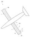
- FIG 1 and 2are a plan view and a state diagram showing the solar panel device provided on the wing of the aircraft according to the present invention.
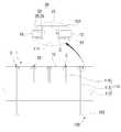
- Figure 3is a perspective view of the wing in the solar panel device provided in the wing of the aircraft according to the present invention.
- 4 to 7is a conceptual diagram showing a state in which the solar panel device provided on the wing of the aircraft according to the invention mounted on the wing.
- a solar panel device (hereinafter referred to as a "panel device") 1 provided on a wing of a vehicle according to the present invention 1is a panel mounted on the wing 100 of the vehicle 200.
- the photovoltaic module (A)while forming the photovoltaic module (A) while being spaced apart from each other in the longitudinal direction crossing the longitudinal direction of the blade (100) on the wing (100), the photovoltaic module (A) is mutually
- a plurality of solar panels 10 constituting the photovoltaic structure (B) and spaced apart from each otherincludes a joint film 20 connecting the solar panels 10.
- the horizontal direction in which the solar panel 10 is disposedis understood as the longitudinal direction of the wing 110 and the longitudinal direction is the front and rear direction intersecting with the longitudinal direction of the wing 110. Therefore, the horizontal and vertical directions to be described later are preferably understood as the direction crossing the longitudinal direction of the wing 100 and the longitudinal direction of the wing 100.
- the solar module Arefers to a state in which the plurality of solar panels 10 are arranged in the vertical direction, and the solar structure B is arranged in the horizontal direction of the plurality of solar modules A. It is to be understood to refer to a state in which it is made.
- the aircraft 200may be formed of an unmanned aircraft for reconnaissance, a wired or wireless aircraft, as well as an aircraft on which a person boards.
- the plurality of solar panels 10are provided in the wing 100 to convert the solar energy to supply the electrical energy required for the vehicle 200.
- the plurality of photovoltaic panels 10each have a rectangular shape and form the photovoltaic structure B while being spaced apart at regular intervals in the horizontal and vertical directions between adjacent photovoltaic panels 10.
- the panel device 1may perform a function of generating an air force by mounting the photovoltaic structure (B) on the wing (100).
- the joint film 20is made of a thin polymer plastic film, so that each solar panel 10 constituting the solar structure (B) can be connected to be spaced apart from each other.
- the joint film 20allows the solar structure (B) to be mounted in a separated state without being adhered to the wing (100).
- the panel device 1may further include a reinforcing plate 30 provided on each lower surface of the plurality of solar panels 10 as shown in FIG. 1.
- the reinforcing plate 30may be made of a metal material or a composite material, and prevents the solar panel 10 from being damaged by the behavior of the wing 100.
- the wing 100has both ends extending in a horizontal direction, and one end includes a frame 110 connected to the vehicle 200 and an outer shell 120 surrounding the frame 110.
- the frame 110has both ends extending in the vertical direction, while the plurality of ribs 111 and both ends extending in the horizontal direction are formed to be spaced apart from each other in the horizontal direction, and the plurality of ribs are formed in the frame 110. It includes a plurality of vanes 112 connecting the 111.
- Each of the plurality of ribs 111extends in a vertical direction from both ends thereof, and the upper and lower portions of the plurality of ribs 111 extend in the horizontal direction from the upper and lower portions of the joint plate 113 and the upper and lower portions of the joint plate 113.
- the upper and lower flanges 114 and 115are formed.
- the rib 111has a longitudinal section 'I' shape as the joint plate 113 and the upper and lower flanges 114 and 115 are connected, and the outer shell 120 is in contact with the upper and lower flanges 114 and 115. While wrapping the frame 110.
- the joint plate 113is formed with a plurality of coupling holes 113a along the longitudinal direction.
- the plurality of coupling holes 113areduces the weight of the joint plate 113 so that the weight of the wing 100 is reduced, and the wing beam 112 may be stably coupled.
- the annulus 112is understood to be coupled to the plurality of ribs 111 while passing through any one of the plurality of coupling holes 113a formed in the plurality of ribs 111, respectively. Should be.
- the winghead 112is preferably made of a pair, it is preferable that the winghead located in the front of the pair of winghead 112 is larger in diameter than the winghead located in the rear.
- the plurality of coupling holes 113amay be smaller in diameter from the front part to the rear part in the longitudinal direction of the joint plate 113.
- the outer shell 120includes an upper outer shell 121 surrounding the upper portion of the frame 110 and a lower outer shell 122 surrounding the lower portion of the frame 110.
- Both ends of the frame 110are formed to extend in the vertical direction, and the upper surface of the frame 110 is positioned on the same surface as the upper surface of the wing beam 122 to support the upper shell 121.
- a plurality of support bar 116may be further included.
- the plurality of support bars 116are located between the wing beams 112, and a plurality of coupling grooves 112a to which the support bars 116 are coupled are formed in the plurality of wing beams 112 along the length direction, respectively. Can be.
- the joint film 20connects the plurality of photovoltaic panels 10 while the pair of films formed with a plurality of hollows 22 to which the photovoltaic panel 10 is coupled is adhered in an up and down direction. Can be.
- the joint film 20is formed with a plurality of hollows 22 to which the solar panel 10 is coupled, and a plurality of vertical sections C positioned between the solar modules A are formed. It may be composed of a plurality of fastening portions 23 that form the base portion 21 and the respective hollows 22 and bind the solar panel 10.
- the plurality of fastening portions 23may be formed to extend inward from the vertical plate 24 and the vertical plate 24, which are vertically extended from the circumference of the hollow 22, respectively.
- a flat plate 25may be formed to extend inward from the vertical plate 24 and the vertical plate 24, which are vertically extended from the circumference of the hollow 22, respectively.
- the panel device 1may form the upper shell 121 as shown in FIG. 4.
- the vertical plate 24extends upward and downward from a circumference of the hollow 22, and the horizontal plate 25 is formed of the vertical plate 24. It is bent inward from the upper and lower ends to form a pair.
- the fastening part 23forms a 'c' shape in which the longitudinal section is opened while the vertical plate 24 and the horizontal plate 25 are integrally connected.
- the plurality of vertical sections Care respectively seated on the plurality of wind beams 112 and the plurality of support bars 116, and an adhesive agent. Or the like.
- the photovoltaic structure Bis separated without being bonded to the frame 110.
- the panel device 1may generate an air force by the photovoltaic structure B, as well as the photovoltaic structure B while being separated from the frame 110. ) Can be prevented from being destroyed by the bending load transmitted from the blade 100.
- the panel device 1may be mounted on the upper shell 121 as shown in FIG. 5.
- the vertical plate 24extends upward from the circumference of the hollow 22 as shown in FIG. 5, and the horizontal plate 25 is formed from the top of the vertical plate 24. It is bent inward.
- the fastening part 23forms a '-' shape in which the vertical section 24 and the horizontal plate 25 are integrally connected, and the inner and lower ends thereof are opened.
- the base portion 21has a lower surface located below or on the same surface as the lower surface of the photovoltaic structure (B).
- the panel device 1is adhesive such that the plurality of longitudinal sections C are positioned on the plurality of vanes 112 and the plurality of support bars 116, respectively, when mounted on the upper surface of the upper shell 121. Or the like.
- the photovoltaic structure (B)is separated without being adhered to the upper shell (121).
- the panel device 1may further include a base film 40 to which the photovoltaic structure B and the base portion 21 are fixed as shown in FIG. 6.
- the base film 40may be modularized by connecting the photovoltaic structure (B), each of the adhesive section (D) corresponding to the plurality of vertical section (C) when mounted on the upper shell 121 It is fixed by an adhesive or the like so as to be positioned on the plurality of vanes 112 and the plurality of support bars 116.
- the base film 40is separated without the lower portion corresponding to the photovoltaic structure (B) is adhered to the upper outer shell 121.
- the panel device 1may be broken by the bending load transmitted from each of the solar panels 10 from the vanes 100 while the solar structure B is separated from the upper shell 121. You can prevent it.
- the panel device 1may be mounted on the lower surface of the upper sheath 121 as shown in FIG.
- the vertical plate 24extends downward from the circumference of the hollow 22 as shown in FIG. 7, and the horizontal plate 25 is formed from the bottom of the vertical plate 24. It is bent inward.
- the fastening portion 23forms a 'b' shape in which the vertical section 24 and the horizontal plate 25 are integrally connected and the longitudinal section is opened on the inside and the top.
- the base portion 21has an upper surface located above or on the same surface as the upper surface of the photovoltaic structure (B).
- the plurality of vertical sections Care attached to the plurality of wing beams 112 and the plurality of support bars 116 by adhesives or the like. While being fixed, it is fixed to the lower surface of the upper shell 121.
- the photovoltaic structure (B)is prevented from being broken by a bending load transmitted to each solar panel 10 while being separated without being adhered to the upper shell 121.
- the panel device 1may be provided with the plurality of panels 10 capable of converting sunlight into energy, as well as the respective panels (eg, by bending load or behavior of the blade 100). 10) can be prevented from being destroyed.
- wing 110frame
- Aphotovoltaic module B: photovoltaic structure
Landscapes
- Engineering & Computer Science (AREA)
- Aviation & Aerospace Engineering (AREA)
- Mechanical Engineering (AREA)
- Photovoltaic Devices (AREA)
Abstract
Description
Translated fromKorean본 발명은 비행체의 날개에 구비되는 태양광 패널장치와 이를 구비한 비행체 날개 및 비행체에 관한 것으로서, 더욱 상세하게는 태양광을 에너지로 변환할 수 있는 패널을 갖는 한편, 날개의 굽힘 하중이나 거동 등에 의해 패널이 파괴되지 않도록 하기 위한 비행체의 날개에 구비되는 태양광 패널장치와 이를 구비한 비행체 날개 및 비행체에 관한 것이다.The present invention relates to a solar panel device provided on the wing of the aircraft, the wing and the aircraft having the same, and more particularly, having a panel capable of converting sunlight into energy, while bending load or behavior of the wing, etc. The present invention relates to a solar panel device provided on a wing of an aircraft for preventing the panel from being destroyed, and a wing and an aircraft having the same.
최근 항공분야에서는 비행을 위한 추진에너지로 태양광을 전기에너지로 변환하여 사용하려 하고 있다.Recently, the aviation field is trying to convert sunlight into electrical energy as a propulsion energy for flight.
이를 위해서는 태양광을 전기에너지로 변환시킬 수 있는 태양광 패널 같은 장치가 필요하고, 태양광의 확보가 용이한 날개 위에 장착되는 것이 바람직하다.To this end, a device such as a solar panel capable of converting sunlight into electrical energy is required, and it is preferable to be mounted on a wing that can easily secure sunlight.
그러나, 일반적으로 태양광 패널은 취성이 강한 Wafer나 Glass등의 재료로 만들어지기 때문에 적은 굽힘만으로도 쉽게 파괴될 수 있는 문제점이 있다.However, in general, since the solar panel is made of a material such as brittle wafer or glass, there is a problem that it can be easily destroyed with only a small bending.
특히, 날개는 항공기 운항시 공력 혹은 중력에 의해 굽힘과 같은 하중을 받게 되고 이에 의하여 태양광 패널에도 굽힘 하중이 작용될 수 있기 때문에 사용이 어렵다는 문제점이 있다.In particular, there is a problem that the wing is difficult to use because the wing is subjected to a load such as bending by aerodynamic or gravity during the flight of the aircraft and thereby the bending load may be applied to the solar panel.
한편, 대한민국 등록특허공보 제10-1275883호에는 유연성을 갖는 태양광 패널 날개구조가 개시되어 있다.On the other hand, Korean Patent Publication No. 10-1275883 discloses a flexible solar panel wing structure.
그러나, 종래의 태양광 패널이 부착된 날개구조는 날개 표면에 호형 구조에 의해 큰 단차가 존재하므로 공력 저항이 크다는 문제점이 있다.However, a wing structure with a conventional solar panel has a problem that the aerodynamic resistance is large because a large step exists due to the arc structure on the wing surface.
본 발명은 상술한 문제점을 해결하기 위해 창안된 것으로서, 본 발명의 목적은 태양광을 에너지로 변환할 수 있는 패널을 갖는 한편, 날개의 굽힘 하중이나 거동 등에 의해 패널이 파괴되지 않도록 하기 위한 비행체의 날개에 구비되는 태양광 패널장치와 이를 구비한 비행체 날개 및 비행체를 제공하는 것이다.The present invention was devised to solve the above problems, and an object of the present invention is to provide a panel capable of converting sunlight into energy, and to prevent the panel from being destroyed by the bending load or behavior of the wing. It is to provide a solar panel device provided on the wing and the wing and the aircraft with the same.
본 발명의 해결하고자 하는 과제는 이상에서 언급된 것들에 한정되지 않으며, 언급되지 아니한 다른 해결과제들은 아래의 기재로부터 당업자에게 명확하게 이해되어 질 수 있을 것이다.The problem to be solved of the present invention is not limited to those mentioned above, other problems not mentioned will be clearly understood by those skilled in the art from the following description.
상술한 목적을 달성하기 위하여, 본 발명은 비행체의 날개에 장착되는 태양광 패널장치로서, 상기 날개에 그 날개의 길이방향과 교차되는 세로방향으로 서로 이격되도록 배치되면서 태양광모듈을 이루는 한편, 그 태양광모듈이 가로방향으로 서로 이격되도록 배치되면서 태양광구조체를 이루는 다수의 태양광패널; 상기 태양광패널 간을 연결하는 이음필름을 포함하는 것을 특징으로 하는 비행체의 날개에 구비되는 태양광 패널장치를 제공한다.In order to achieve the above object, the present invention is a solar panel device which is mounted on the wing of the aircraft, while forming a solar module while being spaced apart from each other in the longitudinal direction intersecting the longitudinal direction of the wing, A plurality of solar panels constituting the solar structure while the solar modules are spaced apart from each other in the horizontal direction; It provides a solar panel device provided on the wing of the aircraft, characterized in that it comprises a joint film connecting the solar panels.
또한, 상기 다수의 태양광 패널의 각 하부면에 구비되는 보강플레이트를 더 포함하는 것을 특징으로 한다.In addition, it characterized in that it further comprises a reinforcing plate provided on each lower surface of the plurality of solar panels.
또한, 상기 태양광구조체가 고정되는 베이스필름을 더 포함하는 것을 특징으로 한다.In addition, the solar structure is characterized in that it further comprises a base film is fixed.
본 발명에 따른 상기 이음필름은, 상기 태양광 패널이 결합되는 다수의 중공이 형성되며, 상기 태양광모듈 간에 위치되는 다수의 세로구간이 형성되는 베이스부; 및 상기 각 중공의 둘레를 이루며, 상기 태양광 패널을 결속하는 다수의 체결부로 이루어지며, 상기 다수의 체결부는, 각각 상기 중공을 이루는 둘레로부터 수직으로 연장 형성되고, 상기 태양광 패널의 측면에 고정되는 수직판; 및 상기 수직판으로부터 내측으로 연장 형성되며, 상기 태양광 패널의 상부면 또는 하부면에 고정되는 수평판을 포함하는 것을 특징으로 한다.The joint film according to the present invention includes a base portion in which a plurality of hollows to which the solar panel is coupled are formed, and a plurality of vertical sections positioned between the solar modules are formed; And a plurality of fastening portions that form the periphery of each hollow and bind the solar panel, wherein the plurality of fastening portions are formed to extend vertically from the periphery of the hollow, respectively, and are fixed to the side of the solar panel Vertical plate; And a horizontal plate extending inwardly from the vertical plate and fixed to an upper surface or a lower surface of the solar panel.
본 발명에 따른 태양광 패널장치를 구비하는 것을 특징으로 하는 비행체의 날개를 제공한다.It provides a wing of the aircraft, characterized in that provided with a solar panel device according to the present invention.
또한, 양단부가 세로 방향으로 연장 형성되는 한편, 가로방향으로 서로 이격되도록 배치되는 복수의 리브와, 양단부가 가로방향으로 연장 형성되며 상기 복수의 리브를 연결하는 복수의 날개보를 포함하는 프레임; 및 상기 프레임의 하부를 감싸는 하부외피와, 상기 프레임의 상부를 감싸는 상부외피를 구비하는 외피를 더 포함하며, 상기 태양광 패널장치는, 상기 상부외피를 이루는 것을 특징으로 한다.In addition, a frame including a plurality of ribs are formed in both ends extending in the longitudinal direction, spaced apart from each other in the horizontal direction, and a plurality of ribs are formed in both ends extending in the horizontal direction connecting the plurality of ribs; And an outer shell surrounding the lower portion of the frame and an upper outer shell surrounding the upper portion of the frame, wherein the solar panel device forms the upper outer shell.
본 발명에 따른 상기 베이스부는, 상기 태양광 패널의 상,하부 사이 중앙부에 위치되며,상기 수직판은, 상기 중공을 이루는 둘레로부터 상,하 방향으로 연장 형성되고, 상기 수평판은, 상기 수직판의 상,하단부로부터 내측으로 절곡되어 한 쌍을 이루면서 상기 태양광 패널의 상,하부에 고정되며, 상기 태양광 패널장치는, 상기 프레임에 상기 다수의 세로구간 중 상기 날개보에 대응되는 세로구간이 그 날개보에 안착, 고정되고, 상기 태양광고정체가 그 프레임과 분리되면서 장착되는 것을 특징으로 한다.The base unit according to the present invention is located in the center between the upper and lower parts of the solar panel, The vertical plate is formed extending in the vertical direction from the circumference forming the hollow, the horizontal plate is bent inward from the upper and lower ends of the vertical plate to form a pair of upper and lower parts of the solar panel The solar panel device may be mounted on the frame while a vertical section corresponding to the wing beam of the plurality of vertical sections is seated and fixed to the wing beam, and the solar advertisement is separated from the frame. It features.
본 발명에 따른 상기 프레임은, 양단부가 세로방향으로 연장 형성되고, 상부면이 상기 날개보의 상부면과 동일면상에 위치되면서 상기 태양광 패널장치를 지지하는 복수의 지지바를 더 포함하며, 상기 태양광 패널장치는, 상기 다수의 세로구간이 각각 상기 복수의 날개보 및 상기 복수의 지지바에 안착, 고정되는 것을 특징으로 한다.The frame according to the present invention further includes a plurality of support bars having both ends extending in a longitudinal direction, and having an upper surface positioned on the same surface as the upper surface of the wind beam and supporting the solar panel device. The optical panel device is characterized in that the plurality of longitudinal sections are respectively seated and fixed to the plurality of vanes and the plurality of support bars.
또한, 양단부가 세로방향으로 연장 형성되는 한편, 가로방향으로 서로 이격되도록 배치되는 복수의 리브와, 양단부가 가로방향으로 연장 형성되며 상기 복수의 리브를 연결하는 복수의 날개보를 포함하는 프레임; 및 상기 프레임의 하부를 감싸는 하부외피와, 상기 프레임의 상부를 감싸는 상부외피를 구비하는 외피를 포함하고, 상기 태양광 패널장치는, 상기 상부외피의 상부면에 장착되는 것을 특징으로 한다.In addition, a frame including a plurality of ribs are formed in both ends extending in the longitudinal direction, spaced apart from each other in the horizontal direction, and a plurality of ribs extending in both ends in the horizontal direction and connecting the plurality of ribs; And an outer shell surrounding the lower portion of the frame and an upper outer shell surrounding the upper portion of the frame, wherein the solar panel device is mounted on an upper surface of the upper outer shell.
본 발명에 따른 상기 베이스부는, 하부면이 상기 태양광구조체의 하부면보다 하측에 위치되거나 동일면 상에 위치되고, 상기 수직판은, 상기 중공을 이루는 둘레로부터 상방향으로 연장 형성되며, 상기 수평판은, 상기 수직판의 상부로부터 내측으로 연장 형성되어 상기 태양광 패널의 상부에 고정되고, 상기 태양광 패널장치는, 상기 상부외피의 상부면에 상기 다수의 세로구간 중 상기 복수의 날개보와 대응되는 세로구간이 그 날개보에 위치되도록 안착, 고정되고, 상기 태양광고정체가 그 상부외피와 분리되면서 장착되는 것을 특징으로 한다.The base portion according to the invention, the lower surface is located below or on the same surface than the lower surface of the photovoltaic structure, the vertical plate is formed extending in the upward direction from the circumference forming the hollow, the horizontal plate is And extending inwardly from an upper portion of the vertical plate to be fixed to an upper portion of the solar panel, wherein the solar panel device corresponds to the plurality of wing beams among the plurality of longitudinal sections on an upper surface of the upper envelope. The vertical section is seated and fixed so as to be positioned on the wing, and the solar advertisement stagnate is mounted while being separated from the upper shell.
본 발명에 따른 상기 프레임은, 양단부가 세로방향으로 연장 형성되고, 상부면이 상기 날개보의 상부면과 동일면상에 위치되면서 상기 태양광 패널장치를 지지하는 복수의 지지바를 더 포함하며, 상기 태양광 패널장치는, 상기 다수의 세로구간이 각각 상기 복수의 날개보 및 상기 복수의 지지바에 위치되도록 안착, 고정되는 것을 특징으로 한다.The frame according to the present invention further includes a plurality of support bars having both ends extending in a longitudinal direction, and having an upper surface positioned on the same surface as the upper surface of the wind beam and supporting the solar panel device. The optical panel device may be seated and fixed so that the plurality of vertical sections are positioned on the plurality of vanes and the plurality of support bars, respectively.
본 발명에 따른 상기 태양광 패널장치는, 상기 태양광구조체 및 상기 베이스부가 고정되는 베이스필름을 더 포함하며, 상기 베이스필름은, 상기 상부외피의 상부면에 상기 다수의 세로구간이 고정되는 세로라인이 각각 상기 복수의 날개보 및 상기 복수의 지지바에 위치되도록 고정되는 것을 특징으로 한다.The photovoltaic panel device according to the present invention further includes a base film to which the solar structure and the base portion are fixed, and the base film has a vertical line on which a plurality of vertical sections are fixed to an upper surface of the upper envelope. It is characterized in that it is fixed to be located in each of the plurality of vanes and the plurality of support bars.
또한, 양단부가 세로방향으로 연장 형성되는 한편, 가로방향으로 서로 이격되도록 배치되는 복수의 리브와, 양단부가 가로방향으로 연장 형성되며 상기 복수의 리브를 연결하는 복수의 날개보를 포함하는 프레임; 및 상기 프레임의 하부를 감싸는 하부외피와, 상기 프레임의 상부를 감싸는 상부외피를 구비하는 외피를 포함하고, 상기 태양광 패널장치는, 상기 상부외피의 하부면에 장착되는 것을 특징으로 한다.In addition, a frame including a plurality of ribs are formed in both ends extending in the longitudinal direction, spaced apart from each other in the horizontal direction, and a plurality of ribs extending in both ends in the horizontal direction and connecting the plurality of ribs; And an outer shell surrounding the lower portion of the frame and an upper outer shell surrounding the upper portion of the frame, wherein the solar panel device is mounted on a lower surface of the upper outer shell.
본 발명에 따른 상기 베이스부는, 상부면이 상기 태양광구조체의 상부면보다 상측에 위치되거나, 동일면 상에 위치되며, 상기 수직판은, 상기 중공을 이루는 둘레로부터 하방향으로 연장 형성되고, 상기 수평판은, 상기 수직판의 하부로부터 내측으로 연장 형성되어 상기 태양광 패널의 하부에 고정되며, 상기 태양광 패널장치는, 상기 다수의 세로구간의 상부가 상기 상부외피의 하부면에 고정되고, 그 다수의 세로구간 중 상기 복수의 날개보와 대응되는 세로구간의 하부가 그 날개보에 안착, 고정되며, 상기 태양광고정체가 그 상부외피와 분리되면서 상기 상부외피의 하부면에 장착되는 것을 특징으로 한다.The base portion according to the present invention, the upper surface is located above the upper surface of the photovoltaic structure, or is located on the same surface, the vertical plate is formed to extend downward from the circumference forming the hollow, the horizontal plate Is formed extending inwardly from a lower portion of the vertical plate and fixed to a lower portion of the solar panel. In the solar panel apparatus, an upper portion of the plurality of vertical sections is fixed to a lower surface of the upper sheath, The lower portion of the vertical section corresponding to the plurality of wing beams of the vertical section of the seating is fixed to the wing beam, characterized in that the solar advertising stagnation is mounted on the lower surface of the upper jacket while being separated from the upper jacket. .
본 발명에 따른 상기 프레임은, 양단부가 세로방향으로 연장 형성되고, 상부면이 상기 날개보의 상부면과 동일면상에 위치되면서 상기 태양광 패널장치를 지지하는 복수의 지지바를 더 포함하며, 상기 태양광 패널장치는, 상기 다수의 세로구간의 하부가 각각 상기 복수의 날개보 및 상기 복수의 지지바에 안착, 고정되는 것을 특징으로 한다.The frame according to the present invention further includes a plurality of support bars having both ends extending in a longitudinal direction, and having an upper surface positioned on the same surface as the upper surface of the wind beam and supporting the solar panel device. The optical panel device is characterized in that the lower portion of the plurality of longitudinal sections are respectively seated and fixed to the plurality of wind beams and the plurality of support bars.
본 발명에 따른 상기 복수의 리브는, 각각 양단부가 세로방향으로 연장 형성되며, 에어포일 형태를 이루는 이음판; 및 상기 이음판의 상,하부로부터 가로방향으로 연장 형성되는 상,하부플랜지를 포함하며, 상기 이음판에는, 길이방향을 따라 복수의 결합공이 형성되고, 상기 복수의 날개보는, 각각 상기 복수의 결합공 중 어느 하나의 결합공에 결합되는 것을 특징으로 한다.The plurality of ribs according to the present invention, each end portion is formed extending in the longitudinal direction, the joint plate forming an airfoil form; And upper and lower flanges extending in a horizontal direction from upper and lower portions of the joint plate, wherein the joint plate has a plurality of coupling holes formed along a longitudinal direction, and the plurality of vanes are respectively coupled to the plurality of vanes. It is characterized in that it is coupled to any one of the coupling holes of the ball.
본 발명에 따른 상기 복수의 결합공은, 상기 이음판의 길이방향을 따라 전방부로부터 후방부로 갈수록 직경이 작아지는 것을 특징으로 한다.The plurality of coupling holes according to the present invention is characterized in that the diameter decreases from the front portion to the rear portion along the longitudinal direction of the joint plate.
본 발명에 따른 상기 복수의 지지바는, 상기 날개보 간에 위치되며, 상기 복수의 날개보에는, 각각 상기 지지바가 결합되는 결합홈이 길이방향을 따라 복수 형성되는 것을 특징으로 한다.The plurality of support bars according to the present invention are located between the wing beams, and each of the plurality of wing beams is characterized in that a plurality of coupling grooves to which the support bars are coupled are formed along the longitudinal direction.
또한, 상기 다수의 태양광 패널의 각 하부면에 구비되는 보강플레이트를 더 포함하는 것을 특징으로 한다.In addition, it characterized in that it further comprises a reinforcing plate provided on each lower surface of the plurality of solar panels.
본 발명에 따른 비행체의 날개를 포함하는 것을 특징으로 하는 비행체를 제공한다.It provides a vehicle comprising a wing of the vehicle according to the invention.
본 발명에 따르면, 항공기의 날개에 태양광 패널을 장착할 수 있는 것은 물론, 그 날개의 굽힘 하중이나 거동 등에 의해 패널이 파괴되지 않도록 할 수 있는 효과가 있다.According to the present invention, the solar panel can be mounted on the wing of the aircraft, and the panel can be prevented from being destroyed by bending load or behavior of the wing.
본 발명의 효과는 이상에서 언급된 것들에 한정되지 않으며, 언급되지 아니한 다른 해결과제들은 아래의 기재로부터 당업자에게 명확하게 이해되어 질 수 있을 것이다.The effects of the present invention are not limited to those mentioned above, and other problems not mentioned will be clearly understood by those skilled in the art from the following description.
도 1 및 도 2는 본 발명에 따른 비행체의 날개에 구비되는 태양광 패널장치를 나타낸 평면도 및 사용 상태도이다.1 and 2 are a plan view and a state diagram showing the solar panel device provided on the wing of the aircraft according to the present invention.
도 3은 본 발명에 따른 비행체의 날개에 구비되는 태양광 패널장치에서 날개를 나타낸 사시도이다.Figure 3 is a perspective view of the wing in the solar panel device provided in the wing of the aircraft according to the present invention.
도 4 내지 도 7은 본 발명에 따른 비행체의 날개에 구비되는 태양광 패널장치가 날개에 장착되는 상태를 나타낸 개념도이다.4 to 7 is a conceptual diagram showing a state in which the solar panel device provided on the wing of the aircraft according to the invention mounted on the wing.
이하, 첨부된 도면에 의하여 본 발명의 바람직한 실시예를 보다 상세하게 설명한다.Hereinafter, with reference to the accompanying drawings will be described in detail a preferred embodiment of the present invention.
도 1 내지 도 7을 참조하여 보면, 본 발명에 따른 비행체의 날개에 구비되는 태양광 패널장치(이하 "패널장치"라 한다)(1)는 비행체(200)의 날개(100)에 장착되는 패널장치로서, 상기 날개(100)에 그 날개(100)의 길이방향과 교차되는 세로방향으로 서로 이격되도록 배치되면서 태양광모듈(A)을 이루는 한편, 그 태양광모듈(A)이 가로방향으로 서로 이격되도록 배치되면서 태양광구조체(B)를 이루는 다수의 태양광패널(10) 및 상기 태양광 패널(10) 간을 연결하는 이음필름(20)을 포함한다.1 to 7, a solar panel device (hereinafter referred to as a "panel device") 1 provided on a wing of a vehicle according to the
여기서, 상기 태양광 패널(10)이 배치되는 가로방향은 상기 날개(110)의 길이방향으로 그리고, 세로방향은 그 날개(110)의 길이방향과 교차되는 전후방향으로 이해되는 것이 바람직하다. 따라서, 후술되는 가로,세로방향은 이와 같이 날개(100)의 길이방향과 그 날개(100)의 길이방향과 교차되는 방향으로 이해되는 것이 바람직하다.Here, it is preferable that the horizontal direction in which the
상기 태양광모듈(A)은 복수의 상기 태양광 패널(10)이 세로방향으로 배치된 상태 지칭하는 것이고, 상기 태양광구조체(B)는 복수의 상기 태양광모듈(A)이 가로방향으로 배치된 상태를 지칭하는 것으로 이해되어야 한다.The solar module A refers to a state in which the plurality of
상기 비행체(200)는 도 2에 도시된 바와 같이 사람이 탑승하는 항공기는 물론, 정찰 등을 위한 무인 항공기 및 유,무선 항공기 등으로 이루어질 수 있다.As shown in FIG. 2, the
상기 다수의 태양광 패널(10)은 상기 날개(100)에 구비되어 태양광 에너지를 변환시켜 상기 비행체(200)에 필요로 하는 전기에너지를 공급한다.The plurality of
상기 다수의 태양광 패널(10)은 각각 사각 형태를 이루며, 서로 인접하는 태양광 패널(10) 간에 가로, 세로방향으로 일정한 간격으로 이격되면서 상기 태양광구조체(B)를 이룬다.The plurality of
상기 패널장치(1)는 상기 날개(100)에 상기 태양광구조체(B)가 장착됨으로써 공기력을 발생시키는 기능을 수행할 수 있다.The
상기 이음필름(20)은 얇은 고분자 플라스틱 필름으로 이루어지며, 상기 태양광구조체(B)를 이루는 각 태양광 패널(10) 간이 서로 이격된 상태로 연결될 수 있도록 한다.The
또한, 상기 이음필름(20)은 상기 태양광구조체(B)가 상기 날개(100)에 접착됨이 없이 분리된 상태로 장착될 수 있도록 한다.In addition, the
이는, 상기 날개(100)로부터 전달되는 굽힘 하중 등에 의해 각 태양광 패널(10) 간이 휘면서 파손이 방지되도록 하는 한편, 그 날개(100)로부터 전달되는 굽힘 하중 등이 그 각 태양광 패널(10)로 전달되지 못하도록 하기 위함이다.This prevents damage between the
상기 패널장치(1)는 도 1에 도시된 바와 같이 상기 다수의 태양광 패널(10)의 각 하부면에 구비되는 보강플레이트(30)를 더 포함할 수 있다.The
상기 보강플레이트(30)는 금속재 또는 복합재 등으로 이루어질 수 있으며, 상기 날개(100)의 거동 등에 의해 상기 태양광 패널(10)이 파손되는 것을 방지한다.The reinforcing
상기 날개(100)는 양단부가 가로방향으로 연장 형성되고, 일단부가 상기 비행체(200)에 연결되는 프레임(110) 및 상기 프레임(110)을 감싸는 외피(120)를 포함한다.The
상기 프레임(110)은 도 3에 도시된 바와 같이 양단부가 세로방향으로 연장 형성되는 한편, 가로방향으로 서로 이격되도록 배치되는 복수의 리브(111) 및 양단부가 가로방향으로 연장 형성되며 상기 복수의 리브(111)를 연결하는 복수의 날개보(112)를 포함한다.As shown in FIG. 3, the
상기 복수의 리브(111)는 각각 양단부가 세로방향으로 연장 형성되며 상,하부가 곡면을 이루면서 에어포일 형태를 이루는 이음판(113) 및 상기 이음판(113)의 상,하부로부터 가로방향으로 연장 형성되는 상,하부플랜지(114,115)를 포함한다.Each of the plurality of
상기 리브(111)는 상기 이음판(113) 및 상기 상,하부플랜지(114,115)가 연결되면서 종단면이 'I'자 형태를 이루며, 상기 외피(120)는 상기 상,하부플랜지(114,115)와 접하면서 상기 프레임(110)을 감싼다.The
상기 이음판(113)에는 길이방향을 따라 복수의 결합공(113a)이 형성된다.The
상기 복수의 결합공(113a)은 상기 이음판(113)의 무게를 감소시켜 상기 날개(100)의 중량이 감속되도록 하는 한편, 상기 날개보(112)가 안정적으로 결합될 수 있도록 한다. 이때의, 상기 날개보(112)는 상기 복수의 리브(111)에 각각 형성되는 상기 복수의 결합공(113a) 중 어느 하나의 결합공을 통과하면서 그 복수의 리브(111)에 결합되는 것으로 이해되어야 한다.The plurality of
상기 날개보(112)는 한 쌍으로 이루어지는 것이 바람직하며, 그 한 쌍의 날개보(112) 중 전방에 위치되는 날개보가 후방에 위치되는 날개보 보다 직경이 크게 형성되는 것이 바람직하다.The
이에 더하여, 상기 복수의 결합공(113a)은 상기 이음판(113)의 길이방향을 따라 전방부로부터 후방부로 갈수록 직경이 작아지는 것이 바람직하다.In addition, the plurality of
상기 외피(120)는 상기 프레임(110)의 상부를 감싸는 상부외피(121) 및 상기 프레임(110)의 하부를 감싸는 하부외피(122)를 포함한다.The
상기 프레임(110)은 양단부가 세로방향으로 연장 형성되고, 상부면이 상기 날개보(122)의 상부면과 동일면상에 위치되면서 상기 상부외피(121)를 지지하는복수의 지지바(116)를 더 포함할 수 있다.Both ends of the
상기 복수의 지지바(116)는 상기 날개보(112) 간에 위치되며, 상기 복수의 날개보(112)에는 각각 상기 지지바(116)가 결합되는 결합홈(112a)이 길이방향을 따라 복수 형성될 수 있다.The plurality of support bars 116 are located between the wing beams 112, and a plurality of
상기 이음필름(20)은 상기 태양광 패널(10)이 결합되는 다수의 중공(22)이 형성되는 한 쌍의 필름이 상,하 방향으로 점착되면서 상기 다수의 태양광 패널(10) 간을 연결할 수 있다.The
이에 의해, 상기 이음필름(20)은 상기 태양광 패널(10)이 결합되는 다수의 중공(22)이 형성되며, 상기 태양광모듈(A) 간에 위치되는 다수의 세로구간(C)이 형성되는 베이스부(21) 및 상기 각 중공(22)의 둘레를 이루며 상기 태양광 패널(10)을 결속하는 다수의 체결부(23)로 이루어질 수 있다.As a result, the
상기 다수의 체결부(23)는 도 1에 도시된 바와 같이 각각 상기 중공(22)을 이루는 둘레로부터 수직으로 연장형성되는 수직판(24) 및 상기 수직판(24)으로부터 내측으로 연장 형성되는 수평판(25)을 포함한다.As shown in FIG. 1, the plurality of
상기 패널장치(1)는 도 4에 도시된 바와 같이 상기 상부외피(121)를 이룰 수 있다.The
예를 들면, 상기 수직판(24)은 도 4에 도시된 바와 같이 상기 중공(22)을 이루는 둘레로부터 상,하 방향으로 연장 형성되며, 상기 수평판(25)은 그 수직판(24)의 상,하단부로부터 내측으로 절곡되면서 한 쌍을 이룬다.For example, as shown in FIG. 4, the
즉, 상기 체결부(23)는 상기 수직판(24) 및 상기 수평판(25)이 일체로 연결되면서 종단면이 내측이 개방되는 'ㄷ'자 형태를 이룬다.That is, the
상기 패널장치(1)는 상기 프레임(110)의 상부에 장착시 상기 다수의 세로구간(C)이 각각 상기 복수의 날개보(112) 및 상기 복수의 지지바(116)에 안착되는 한편, 접착제 등에 의해 고정된다.When the
상기 태양광구조체(B)는 상기 프레임(110)과 접착됨이 없이 분리된다.The photovoltaic structure B is separated without being bonded to the
이로 인해, 상기 패널장치(1)는 상기 태양광구조체(B)에 의해 공기력을 발생시킬 수 있는 것은 물론, 그 태양광구조체(B)가 상기 프레임(110)과 분리되면서 각 태양광 패널(10)이 상기 날개(100)로부터 전달되는 굽힘 하중 등에 의해 파괴되는 것을 방지할 수 있다.As a result, the
상기 패널장치(1)는 도 5에 도시된 바와 같이 상기 상부외피(121)에 장착될 수 있다.The
예를 들면, 상기 수직판(24)은 도 5에 도시된 바와 같이 상기 중공(22)을 이루는 둘레로부터 상방향으로 연장 형성되며, 상기 수평판(25)은 그 수직판(24)의 상부로부터 내측으로 절곡된다.For example, the
즉, 상기 체결부(23)는 상기 수직판(24) 및 상기 수평판(25)이 일체로 연결되면서 종단면이 내측 및 하부가 개방되는 'ㄱ'자 형태를 이룬다.That is, the
상기 베이스부(21)는 하부면이 상기 태양광구조체(B)의 하부면보다 하측에 위치되거나 동일면 상에 위치된다.The
상기 패널장치(1)는 상기 상부외피(121)의 상부면에 장착시 상기 다수의 세로구간(C)이 각각 상기 복수의 날개보(112) 및 상기 복수의 지지바(116)에 위치되도록 접착제 등에 의해 고정된다.The
상기 태양광구조체(B)는 상기 상부외피(121)와 접착됨이 없이 분리된다.The photovoltaic structure (B) is separated without being adhered to the upper shell (121).
상기 패널장치(1)는 도 6에 도시된 바와 같이 상기 태양광구조체(B) 및 상기 베이스부(21)가 고정되는 베이스필름(40)을 더 포함할 수 있다.The
상기 베이스필름(40)은 상기 태양광구조체(B)를 연결하여 모듈화될 수 있도록 하며, 상기 상부외피(121)에 장착시 상기 다수의 세로구간(C)과 대응되는 접착구간(D)이 각각 상기 복수의 날개보(112) 및 상기 복수의 지지바(116)에 위치되도록 접착제 등에 의해 고정된다.The
상기 베이스필름(40)은 상기 태양광구조체(B)와 대응되는 하부가 상기 상부외피(121)와 접착됨이 없이 분리된다.The
이로 인해, 상기 패널장치(1)는 상기 태양광구조체(B)가 상기 상부외피(121)와 분리되면서 각 태양광 패널(10)이 상기 날개(100)로부터 전달되는 굽힘 하중 등에 의해 파괴되는 것을 방지할 수 있다.As a result, the
상기 패널장치(1)는 도 7에 도시된 바와 같이 상기 상부외피(121)의 하부면에 장착될 수 있다. The
예를 들면, 상기 수직판(24)은 도 7에 도시된 바와 같이 상기 중공(22)을 이루는 둘레로부터 하방향으로 연장 형성되며, 상기 수평판(25)은 그 수직판(24)의 하부로부터 내측으로 절곡된다.For example, the
즉, 상기 체결부(23)는 상기 수직판(24) 및 상기 수평판(25)이 일체로 연결되면서 종단면이 내측 및 상부가 개방되는 'ㄴ'자 형태를 이룬다.That is, the
상기 베이스부(21)는 상부면이 상기 태양광구조체(B)의 상부면보다 상측에 위치되거나 동일면 상에 위치된다.The
상기 패널장치(1)는 상기 상부외피(121)의 하부면에 장착시 상기 다수의 세로구간(C)이 각각 상기 복수의 날개보(112) 및 상기 복수의 지지바(116)에 접착제 등에 의해 고정되는 한편, 상기 상부외피(121)의 하부면에 고정된다.When the
상기 태양광구조체(B)는 상기 상부외피(121)와 접착됨이 없이 분리되면서 각 태양열 패널(10)로 전달되는 굽힙 하중 등에 의해 파괴되는 것이 방지된다.The photovoltaic structure (B) is prevented from being broken by a bending load transmitted to each
이로 인해, 상기 패널장치(1)는 태양광을 에너지로 변환할 수 있는 상기 다수의 패널(10)을 구비할 수 있는 것은 물론, 상기 날개(100)의 굽힘 하중이나 거동 등에 의해 그 각 패널(10)이 파괴되는 것을 방지할 수 있다.For this reason, the
이상에서 설명한 것은 본 발명에 따른 비행체의 날개에 구비되는 태양광 패널장치와 이를 구비한 비행체 날개 및 비행체를 실시하기 위한 실시 예에 불과한 것으로서, 본 발명은 상기한 실시 예에 한정되지 않고, 이하의 특허청구범위에서 청구하는 바와 같이 본 발명의 요지를 벗어남이 없이 당해 발명이 속하는 분야에서 통상의 지식을 가진 자라면 누구든지 다양한 변경 실시가 가능한 범위까지 본 발명의 기술적 정신이 있다고 할 것이다.What has been described above is only an embodiment for carrying out the solar panel device provided on the wing of the aircraft according to the present invention, the wing and the aircraft having the same, the present invention is not limited to the above embodiments, As claimed in the claims, any person having ordinary skill in the art without departing from the gist of the present invention will have the technical spirit of the present invention to the extent that various modifications can be made.
(부호의 설명)(Explanation of the sign)
1 : 태양광 패널장치 10 : 태양광 패널1: solar panel device 10: solar panel
20 : 이음필름 21 : 베이스부20: joint film 21: the base portion
22 : 중공 23 : 체결부22: hollow 23: fastening part
24 : 수직판 25 : 수평판24: vertical plate 25: horizontal plate
30 : 보강플레이트 40 : 베이스필름30: reinforcing plate 40: base film
100 : 날개 110 : 프레임100: wing 110: frame
111 : 리브 112 : 날개보111: rib 112: wing beam
112a : 결합홈 113 : 이음판112a: coupling groove 113: joint plate
113a : 결합공 114 : 상부플랜지113a: coupling hole 114: upper flange
115 : 하부플랜지 116 : 지지바115: lower flange 116: support bar
120 : 외피 121 : 상부외피120: jacket 121: upper jacket
122 : 하부외피 200 : 비행체122: lower jacket 200: aircraft
A : 태양광모듈 B : 태양광구조체A: photovoltaic module B: photovoltaic structure
C : 세로구간 D : 접착구간C: vertical section D: adhesive section
Claims (20)
Translated fromKoreanPriority Applications (1)
| Application Number | Priority Date | Filing Date | Title |
|---|---|---|---|
| US14/892,642US20160325819A1 (en) | 2014-12-08 | 2014-12-10 | Solar panel device provided on aircraft wing, aircraft wing having solar panel device, and aircraft |
Applications Claiming Priority (2)
| Application Number | Priority Date | Filing Date | Title |
|---|---|---|---|
| KR10-2014-0174682 | 2014-12-08 | ||
| KR1020140174682AKR101634877B1 (en) | 2014-12-08 | 2014-12-08 | Solar power pannel apparatus having wing of plane, wing of plane and plane |
Publications (1)
| Publication Number | Publication Date |
|---|---|
| WO2016093389A1true WO2016093389A1 (en) | 2016-06-16 |
Family
ID=56107560
Family Applications (1)
| Application Number | Title | Priority Date | Filing Date |
|---|---|---|---|
| PCT/KR2014/012130WO2016093389A1 (en) | 2014-12-08 | 2014-12-10 | Solar panel device included in flight vehicle wing, and flight vehicle wing and flight vehicle including same |
Country Status (3)
| Country | Link |
|---|---|
| US (1) | US20160325819A1 (en) |
| KR (1) | KR101634877B1 (en) |
| WO (1) | WO2016093389A1 (en) |
Cited By (1)
| Publication number | Priority date | Publication date | Assignee | Title |
|---|---|---|---|---|
| CN114614183A (en)* | 2022-03-04 | 2022-06-10 | 上海沃兰特航空技术有限责任公司 | Battery package mounting structure and electric aircraft |
Families Citing this family (2)
| Publication number | Priority date | Publication date | Assignee | Title |
|---|---|---|---|---|
| US10954005B1 (en)* | 2016-07-25 | 2021-03-23 | Space Systems/Loral, Llc | Power train for deep space solar electric propulsion |
| CN110576963B (en)* | 2019-09-19 | 2023-03-24 | 西北工业大学 | Solar unmanned aerial vehicle wing structure |
Citations (5)
| Publication number | Priority date | Publication date | Assignee | Title |
|---|---|---|---|---|
| US5810284A (en)* | 1995-03-15 | 1998-09-22 | Hibbs; Bart D. | Aircraft |
| JP2006028803A (en)* | 2004-07-13 | 2006-02-02 | Tsutsunaka Plast Ind Co Ltd | Sheet waterproof type photovoltaic power generation panel set, and its construction method and construction structure |
| JP2010212405A (en)* | 2009-03-10 | 2010-09-24 | Taisei Corp | Solar power system |
| KR20130059022A (en)* | 2011-11-28 | 2013-06-05 | 한국과학기술연구원 | Wing structure having a solar battery and manufacturing method thereof |
| KR101275883B1 (en)* | 2011-12-27 | 2013-06-24 | 한국항공우주연구원 | Flexible solar panel wing structure |
Family Cites Families (2)
| Publication number | Priority date | Publication date | Assignee | Title |
|---|---|---|---|---|
| JP4325213B2 (en)* | 2003-02-18 | 2009-09-02 | 富士電機システムズ株式会社 | Portable solar panel |
| US20150203187A1 (en)* | 2013-04-02 | 2015-07-23 | The Boeing Company | Continuously Curved Spar and Method of Manufacturing |
- 2014
- 2014-12-08KRKR1020140174682Apatent/KR101634877B1/enactiveActive
- 2014-12-10USUS14/892,642patent/US20160325819A1/ennot_activeAbandoned
- 2014-12-10WOPCT/KR2014/012130patent/WO2016093389A1/enactiveApplication Filing
Patent Citations (5)
| Publication number | Priority date | Publication date | Assignee | Title |
|---|---|---|---|---|
| US5810284A (en)* | 1995-03-15 | 1998-09-22 | Hibbs; Bart D. | Aircraft |
| JP2006028803A (en)* | 2004-07-13 | 2006-02-02 | Tsutsunaka Plast Ind Co Ltd | Sheet waterproof type photovoltaic power generation panel set, and its construction method and construction structure |
| JP2010212405A (en)* | 2009-03-10 | 2010-09-24 | Taisei Corp | Solar power system |
| KR20130059022A (en)* | 2011-11-28 | 2013-06-05 | 한국과학기술연구원 | Wing structure having a solar battery and manufacturing method thereof |
| KR101275883B1 (en)* | 2011-12-27 | 2013-06-24 | 한국항공우주연구원 | Flexible solar panel wing structure |
Cited By (1)
| Publication number | Priority date | Publication date | Assignee | Title |
|---|---|---|---|---|
| CN114614183A (en)* | 2022-03-04 | 2022-06-10 | 上海沃兰特航空技术有限责任公司 | Battery package mounting structure and electric aircraft |
Also Published As
| Publication number | Publication date |
|---|---|
| US20160325819A1 (en) | 2016-11-10 |
| KR20160069540A (en) | 2016-06-17 |
| KR101634877B1 (en) | 2016-06-30 |
Similar Documents
| Publication | Publication Date | Title |
|---|---|---|
| WO2014129800A1 (en) | Supporting system for solar panel array | |
| WO2018155752A1 (en) | Solar cell module | |
| CN107078685A (en) | Solar panel and method of manufacturing solar power generation device | |
| WO2016093389A1 (en) | Solar panel device included in flight vehicle wing, and flight vehicle wing and flight vehicle including same | |
| WO2013008986A1 (en) | Offshore wind power generator, lifting jig for transferring the offshore wind power generator, and method and system for installing the offshore wind power generator using the lifting jig | |
| WO2014107090A1 (en) | Thermal pad for secondary battery and battery module comprising same | |
| WO2013032193A2 (en) | Battery system and method for connecting a battery cell assembly to a non-conductive base material member | |
| WO2011062380A2 (en) | Solar photovoltaic device | |
| WO2015026035A1 (en) | Display device | |
| WO2011040784A2 (en) | Solar photovoltaic device | |
| WO2010053301A2 (en) | Functional sheet and solar cell module including same | |
| CN207099024U (en) | Photovoltaic module array | |
| WO2013100283A1 (en) | Round and polyhedral segment solar energy and wind power generation system | |
| JPH0669527A (en) | Solar cell module | |
| WO2019107793A1 (en) | Solar panel support | |
| WO2012157964A1 (en) | Solar power generation system in the form of blinds, and light and heat emitting apparatus for greenhouse using photovoltaic power generation system in the form of blinds | |
| WO2012165683A1 (en) | Signboard using solar cells | |
| WO2019091031A1 (en) | Method for forming integral solar support power generation column | |
| WO2016017865A1 (en) | Floating solar power generation system | |
| WO2018034403A1 (en) | Structure for installing photovoltaic module by using wire | |
| WO2020032361A1 (en) | Photovoltaic panel assembly and photovoltaic panel device comprising same | |
| WO2025005603A1 (en) | Cylindrical photovoltaic apparatus | |
| WO2014034976A1 (en) | Dye-sensitized solar cell module connection frame and window provided with dye-sensitized solar cell module including same | |
| CN207956093U (en) | A kind of unmanned plane dismounting portable type optical zoom high definition video camera | |
| WO2021162225A1 (en) | Floating solar energy generation device |
Legal Events
| Date | Code | Title | Description |
|---|---|---|---|
| WWE | Wipo information: entry into national phase | Ref document number:14892642 Country of ref document:US | |
| 121 | Ep: the epo has been informed by wipo that ep was designated in this application | Ref document number:14907979 Country of ref document:EP Kind code of ref document:A1 | |
| NENP | Non-entry into the national phase | Ref country code:DE | |
| 122 | Ep: pct application non-entry in european phase | Ref document number:14907979 Country of ref document:EP Kind code of ref document:A1 |