WO2016078517A1 - Self-moving robot - Google Patents
Self-moving robotDownload PDFInfo
- Publication number
- WO2016078517A1 WO2016078517A1PCT/CN2015/094050CN2015094050WWO2016078517A1WO 2016078517 A1WO2016078517 A1WO 2016078517A1CN 2015094050 WCN2015094050 WCN 2015094050WWO 2016078517 A1WO2016078517 A1WO 2016078517A1
- Authority
- WO
- WIPO (PCT)
- Prior art keywords
- module
- unit
- interface
- energy
- self
- Prior art date
Links
- 238000001514detection methodMethods0.000claimsdescription19
- 238000012546transferMethods0.000claimsdescription7
- 241001417527PempheridaeSpecies0.000claimsdescription5
- 239000003337fertilizerSubstances0.000claimsdescription5
- 239000007788liquidSubstances0.000description119
- 238000004140cleaningMethods0.000description71
- 238000003032molecular dockingMethods0.000description62
- 244000025254Cannabis sativaSpecies0.000description29
- 230000013011matingEffects0.000description21
- 238000000034methodMethods0.000description21
- 230000006870functionEffects0.000description19
- 238000005520cutting processMethods0.000description18
- 238000007664blowingMethods0.000description12
- 238000010408sweepingMethods0.000description12
- 238000012544monitoring processMethods0.000description11
- 238000010586diagramMethods0.000description10
- 238000005507sprayingMethods0.000description10
- 238000007599dischargingMethods0.000description8
- 239000000428dustSubstances0.000description8
- XLYOFNOQVPJJNP-UHFFFAOYSA-NwaterSubstancesOXLYOFNOQVPJJNP-UHFFFAOYSA-N0.000description5
- 238000004891communicationMethods0.000description4
- 238000013461designMethods0.000description4
- 239000002184metalSubstances0.000description4
- 238000013459approachMethods0.000description3
- 230000009286beneficial effectEffects0.000description3
- 238000009826distributionMethods0.000description3
- 239000000463materialSubstances0.000description3
- 230000002093peripheral effectEffects0.000description3
- 239000003086colorantSubstances0.000description2
- 230000000694effectsEffects0.000description2
- 238000004146energy storageMethods0.000description2
- 239000000284extractSubstances0.000description2
- 230000004720fertilizationEffects0.000description2
- 230000006698inductionEffects0.000description2
- 238000003780insertionMethods0.000description2
- 230000037431insertionEffects0.000description2
- 238000004519manufacturing processMethods0.000description2
- 230000015654memoryEffects0.000description2
- 230000008054signal transmissionEffects0.000description2
- 239000013589supplementSubstances0.000description2
- 244000292693Poa annuaSpecies0.000description1
- 230000003466anti-cipated effectEffects0.000description1
- 230000007812deficiencyEffects0.000description1
- 238000005265energy consumptionMethods0.000description1
- 230000007613environmental effectEffects0.000description1
- 239000012530fluidSubstances0.000description1
- 239000012634fragmentSubstances0.000description1
- 238000012423maintenanceMethods0.000description1
- 239000000575pesticideSubstances0.000description1
- 239000000047productSubstances0.000description1
- 230000011218segmentationEffects0.000description1
- 239000002689soilSubstances0.000description1
- 239000007921spraySubstances0.000description1
- 239000011232storage materialSubstances0.000description1
- 238000006467substitution reactionMethods0.000description1
Images


Classifications
- A—HUMAN NECESSITIES
- A01—AGRICULTURE; FORESTRY; ANIMAL HUSBANDRY; HUNTING; TRAPPING; FISHING
- A01D—HARVESTING; MOWING
- A01D34/00—Mowers; Mowing apparatus of harvesters
- A01D34/006—Control or measuring arrangements
- A01D34/008—Control or measuring arrangements for automated or remotely controlled operation
- B—PERFORMING OPERATIONS; TRANSPORTING
- B25—HAND TOOLS; PORTABLE POWER-DRIVEN TOOLS; MANIPULATORS
- B25J—MANIPULATORS; CHAMBERS PROVIDED WITH MANIPULATION DEVICES
- B25J5/00—Manipulators mounted on wheels or on carriages
- A—HUMAN NECESSITIES
- A01—AGRICULTURE; FORESTRY; ANIMAL HUSBANDRY; HUNTING; TRAPPING; FISHING
- A01D—HARVESTING; MOWING
- A01D42/00—Mowers convertible to apparatus for purposes other than mowing; Mowers capable of performing operations other than mowing
- A—HUMAN NECESSITIES
- A01—AGRICULTURE; FORESTRY; ANIMAL HUSBANDRY; HUNTING; TRAPPING; FISHING
- A01G—HORTICULTURE; CULTIVATION OF VEGETABLES, FLOWERS, RICE, FRUIT, VINES, HOPS OR SEAWEED; FORESTRY; WATERING
- A01G25/00—Watering gardens, fields, sports grounds or the like
- A01G25/09—Watering arrangements making use of movable installations on wheels or the like
- A—HUMAN NECESSITIES
- A47—FURNITURE; DOMESTIC ARTICLES OR APPLIANCES; COFFEE MILLS; SPICE MILLS; SUCTION CLEANERS IN GENERAL
- A47L—DOMESTIC WASHING OR CLEANING; SUCTION CLEANERS IN GENERAL
- A47L7/00—Suction cleaners adapted for additional purposes; Tables with suction openings for cleaning purposes; Containers for cleaning articles by suction; Suction cleaners adapted to cleaning of brushes; Suction cleaners adapted to taking-up liquids
- A47L7/0085—Suction cleaners adapted for additional purposes; Tables with suction openings for cleaning purposes; Containers for cleaning articles by suction; Suction cleaners adapted to cleaning of brushes; Suction cleaners adapted to taking-up liquids adapted for special purposes not related to cleaning
- A—HUMAN NECESSITIES
- A47—FURNITURE; DOMESTIC ARTICLES OR APPLIANCES; COFFEE MILLS; SPICE MILLS; SUCTION CLEANERS IN GENERAL
- A47L—DOMESTIC WASHING OR CLEANING; SUCTION CLEANERS IN GENERAL
- A47L9/00—Details or accessories of suction cleaners, e.g. mechanical means for controlling the suction or for effecting pulsating action; Storing devices specially adapted to suction cleaners or parts thereof; Carrying-vehicles specially adapted for suction cleaners
- A47L9/009—Carrying-vehicles; Arrangements of trollies or wheels; Means for avoiding mechanical obstacles
- B—PERFORMING OPERATIONS; TRANSPORTING
- B25—HAND TOOLS; PORTABLE POWER-DRIVEN TOOLS; MANIPULATORS
- B25J—MANIPULATORS; CHAMBERS PROVIDED WITH MANIPULATION DEVICES
- B25J19/00—Accessories fitted to manipulators, e.g. for monitoring, for viewing; Safety devices combined with or specially adapted for use in connection with manipulators
- B25J19/005—Accessories fitted to manipulators, e.g. for monitoring, for viewing; Safety devices combined with or specially adapted for use in connection with manipulators using batteries, e.g. as a back-up power source
- B—PERFORMING OPERATIONS; TRANSPORTING
- B25—HAND TOOLS; PORTABLE POWER-DRIVEN TOOLS; MANIPULATORS
- B25J—MANIPULATORS; CHAMBERS PROVIDED WITH MANIPULATION DEVICES
- B25J9/00—Programme-controlled manipulators
- B25J9/08—Programme-controlled manipulators characterised by modular constructions
- B—PERFORMING OPERATIONS; TRANSPORTING
- B60—VEHICLES IN GENERAL
- B60L—PROPULSION OF ELECTRICALLY-PROPELLED VEHICLES; SUPPLYING ELECTRIC POWER FOR AUXILIARY EQUIPMENT OF ELECTRICALLY-PROPELLED VEHICLES; ELECTRODYNAMIC BRAKE SYSTEMS FOR VEHICLES IN GENERAL; MAGNETIC SUSPENSION OR LEVITATION FOR VEHICLES; MONITORING OPERATING VARIABLES OF ELECTRICALLY-PROPELLED VEHICLES; ELECTRIC SAFETY DEVICES FOR ELECTRICALLY-PROPELLED VEHICLES
- B60L1/00—Supplying electric power to auxiliary equipment of vehicles
- B60L1/003—Supplying electric power to auxiliary equipment of vehicles to auxiliary motors, e.g. for pumps, compressors
- B—PERFORMING OPERATIONS; TRANSPORTING
- B60—VEHICLES IN GENERAL
- B60L—PROPULSION OF ELECTRICALLY-PROPELLED VEHICLES; SUPPLYING ELECTRIC POWER FOR AUXILIARY EQUIPMENT OF ELECTRICALLY-PROPELLED VEHICLES; ELECTRODYNAMIC BRAKE SYSTEMS FOR VEHICLES IN GENERAL; MAGNETIC SUSPENSION OR LEVITATION FOR VEHICLES; MONITORING OPERATING VARIABLES OF ELECTRICALLY-PROPELLED VEHICLES; ELECTRIC SAFETY DEVICES FOR ELECTRICALLY-PROPELLED VEHICLES
- B60L53/00—Methods of charging batteries, specially adapted for electric vehicles; Charging stations or on-board charging equipment therefor; Exchange of energy storage elements in electric vehicles
- B60L53/10—Methods of charging batteries, specially adapted for electric vehicles; Charging stations or on-board charging equipment therefor; Exchange of energy storage elements in electric vehicles characterised by the energy transfer between the charging station and the vehicle
- B60L53/14—Conductive energy transfer
- B60L53/16—Connectors, e.g. plugs or sockets, specially adapted for charging electric vehicles
- B—PERFORMING OPERATIONS; TRANSPORTING
- B60—VEHICLES IN GENERAL
- B60L—PROPULSION OF ELECTRICALLY-PROPELLED VEHICLES; SUPPLYING ELECTRIC POWER FOR AUXILIARY EQUIPMENT OF ELECTRICALLY-PROPELLED VEHICLES; ELECTRODYNAMIC BRAKE SYSTEMS FOR VEHICLES IN GENERAL; MAGNETIC SUSPENSION OR LEVITATION FOR VEHICLES; MONITORING OPERATING VARIABLES OF ELECTRICALLY-PROPELLED VEHICLES; ELECTRIC SAFETY DEVICES FOR ELECTRICALLY-PROPELLED VEHICLES
- B60L53/00—Methods of charging batteries, specially adapted for electric vehicles; Charging stations or on-board charging equipment therefor; Exchange of energy storage elements in electric vehicles
- B60L53/10—Methods of charging batteries, specially adapted for electric vehicles; Charging stations or on-board charging equipment therefor; Exchange of energy storage elements in electric vehicles characterised by the energy transfer between the charging station and the vehicle
- B60L53/14—Conductive energy transfer
- B60L53/18—Cables specially adapted for charging electric vehicles
- G—PHYSICS
- G05—CONTROLLING; REGULATING
- G05D—SYSTEMS FOR CONTROLLING OR REGULATING NON-ELECTRIC VARIABLES
- G05D1/00—Control of position, course, altitude or attitude of land, water, air or space vehicles, e.g. using automatic pilots
- G05D1/20—Control system inputs
- G05D1/24—Arrangements for determining position or orientation
- G05D1/244—Arrangements for determining position or orientation using passive navigation aids external to the vehicle, e.g. markers, reflectors or magnetic means
- G—PHYSICS
- G05—CONTROLLING; REGULATING
- G05D—SYSTEMS FOR CONTROLLING OR REGULATING NON-ELECTRIC VARIABLES
- G05D1/00—Control of position, course, altitude or attitude of land, water, air or space vehicles, e.g. using automatic pilots
- G05D1/60—Intended control result
- G05D1/656—Interaction with payloads or external entities
- G05D1/661—Docking at a base station
- A—HUMAN NECESSITIES
- A47—FURNITURE; DOMESTIC ARTICLES OR APPLIANCES; COFFEE MILLS; SPICE MILLS; SUCTION CLEANERS IN GENERAL
- A47L—DOMESTIC WASHING OR CLEANING; SUCTION CLEANERS IN GENERAL
- A47L2201/00—Robotic cleaning machines, i.e. with automatic control of the travelling movement or the cleaning operation
- A47L2201/02—Docking stations; Docking operations
- A47L2201/026—Refilling cleaning liquid containers
- G—PHYSICS
- G05—CONTROLLING; REGULATING
- G05D—SYSTEMS FOR CONTROLLING OR REGULATING NON-ELECTRIC VARIABLES
- G05D2105/00—Specific applications of the controlled vehicles
- G05D2105/15—Specific applications of the controlled vehicles for harvesting, sowing or mowing in agriculture or forestry
- G—PHYSICS
- G05—CONTROLLING; REGULATING
- G05D—SYSTEMS FOR CONTROLLING OR REGULATING NON-ELECTRIC VARIABLES
- G05D2107/00—Specific environments of the controlled vehicles
- G05D2107/20—Land use
- G05D2107/23—Gardens or lawns
- G—PHYSICS
- G05—CONTROLLING; REGULATING
- G05D—SYSTEMS FOR CONTROLLING OR REGULATING NON-ELECTRIC VARIABLES
- G05D2109/00—Types of controlled vehicles
- G05D2109/10—Land vehicles
- G—PHYSICS
- G05—CONTROLLING; REGULATING
- G05D—SYSTEMS FOR CONTROLLING OR REGULATING NON-ELECTRIC VARIABLES
- G05D2111/00—Details of signals used for control of position, course, altitude or attitude of land, water, air or space vehicles
- G05D2111/10—Optical signals
- G—PHYSICS
- G05—CONTROLLING; REGULATING
- G05D—SYSTEMS FOR CONTROLLING OR REGULATING NON-ELECTRIC VARIABLES
- G05D2111/00—Details of signals used for control of position, course, altitude or attitude of land, water, air or space vehicles
- G05D2111/30—Radio signals
- G05D2111/34—Radio signals generated by transmitters powered by energy received from an external transceiver, e.g. generated by passive radio-frequency identification [RFID] tags
Definitions
- the inventionrelates to a self-mobile robot. More particularly, the present invention relates to a modular self-mobile robot.
- Automated home devicessuch as automatic vacuum cleaners
- This automated home deviceis also called automatic work equipment, automatic robots, and the like.
- a variety of specialized automatic robotssuch as automatic vacuum cleaners, automatic security robots, automatic lawn mowers, and automatic watering machines have emerged for various needs of home users.
- the problem that arisesis that users need to purchase different automatic devices for different needs. For example, a user may have an automatic vacuum cleaner and a security robot in the room, and an automatic lawn mower, automatic watering machine, automatic hair dryer, etc. Wait. This is first of all expensive, and secondly it leads to a messy family environment.
- each type of automatic equipmentneeds to separately arrange the charging station and related lines.
- the outdoor machinealso needs to arrange different boundary signal lines for different systems, and these boundary signal lines may also interfere with each other.
- the object of the present inventionis to provide a low-cost, multi-function self-mobile robot system. System.
- a self-mobile robotcomprising at least one of a self-moving module and a plurality of work modules connected to the self-moving module;
- the self-moving moduleincludes a control unit, a first energy unit, a first walking unit, and a first interface unit, the control unit executing a predetermined instruction to control operation from the mobile robot;
- the first energy unitincluding a rechargeable battery, a self-moving module or a self-moving
- the robotprovides energy;
- the first walking unitassists walking from the moving module;
- the working moduleincludes a first working unit, a second walking unit, and a second interface unit, the first working unit performing a specific type of work,
- the second walking unitassists the working module to walk;
- the first interface unit and the second interface unitcan be correspondingly coupled to connect the working module to the self-moving module, the working module further comprising a second energy unit, the first
- the energy unitincludes a rechargeable battery, and the second energy unit provides energy to the working module or the self
- the self-moving modulefurther comprises a second working unit, the second working unit performing a specific type of work.
- the working moduleis provided with a charging interface, and the charging interface can be connected with an external power interface to receive charging power.
- the charging interface and the power interfaceare both wireless charging interfaces.
- the first interface unitincludes a first energy interface, a first control interface, and a first mechanical interface
- the second interface unitincludes a second energy interface, a second control interface, and a second mechanical interface
- the first energy interface and the second energy interfaceare docked to transfer energy between the mobile module and the working module
- the first control interface and the second control interfaceare docked to be in the self-moving module.
- a signalis transmitted between the working module and the second mechanical interface to connect the self-moving module and the working module together.
- the self-moving modulecomprises a charging interface
- the working moduleis connected to an external power interface through a second energy interface, a first energy interface and the charging interface to receive charging electrical energy.
- the charging interfaceincludes a first charging pole piece group and a second charging pole piece group, the first charging pole piece group is connected to the first energy unit to charge thereto, and the second charging pole piece group passes A first energy interface, a second energy interface is coupled to the second energy unit to charge thereto.
- the self-moving modulefurther includes a detecting unit, and the detecting unit detects the working module and Sending the detection result to the control unit; the control unit determines whether the working module to be connected is detected according to the detection result, and when the determination result is YES, the control unit controls the first walking unit to walk to make the self-moving module and the The working module connections that need to be connected.
- the working moduleis at least one of a lawn mower module, a sweeper module, a snow sweeper module, a blower module, a fertilizer applicator module, and a sprinkler module.
- control unitmonitors energy levels of the first energy unit and the second energy unit, and when the energy level of the second energy unit is greater than the first threshold, controlling the second energy unit to provide energy to the working module;
- the first energy unitis controlled to provide energy to the working module when the energy level of the unit is less than the first threshold and the energy level of the first energy unit is greater than the second threshold.
- the self-moving modulefurther includes a detecting unit, the detecting unit detects the working module and sends the detection result to the control unit; and the control unit determines, according to the detection result, whether the working module to be connected is detected, when the determination result is In the case of YES, the control unit controls the first walking unit to walk to connect the self-moving module to the working module to be connected.
- the working module or the working moduleis provided with a working module identifier corresponding to the working module, and the detecting module detects the working module by detecting the working module identifier.
- the working moduleis identified as an RFID tag
- the detecting moduleis an RFI D reader.
- the working moduleis identified as an image identifier
- the detecting moduleis an image capturing device.
- the imageis identified as a barcode or a two-dimensional code.
- the control unitwalks along the guiding unit according to the received detection result to approach the working module.
- the guiding unitis an electrical signal line or a metal rail; and the guiding detecting unit corresponds to an electrical signal sensing unit or a metal sensing unit.
- the first interface unitincludes a first energy interface, a first control interface, and a first mechanical interface
- the second interface unitincludes a second energy interface, a second control interface, and a second mechanical interface
- the first energy interface and the second energy interfaceare docked to transfer energy between the mobile module and the working module
- the first control interface and the second control interfaceare docked to be in the self-moving module. Passing a signal between the working module, the first mechanical interface and the second mechanical interface Connect the self-moving module and the working module together.
- control moduleselectively controls the first mechanical interface and the second mechanical interface to establish or disconnect.
- one of the first mechanical interface and the second mechanical interfaceis provided with an electromagnet, wherein the other is provided with a material that can be attracted to the electromagnet, and the control module controls the polarity of the electromagnet.
- the first mechanical interface and the second mechanical interfaceare connected or disconnected.
- the beneficial effects of the present inventionare: the self-moving robot realizes unattended execution of various types of work tasks in the work area by setting the self-moving module and the interchangeable work module,
- the moduleis provided with a separate energy unit, which has sufficient energy and long battery life.
- the present inventionalso provides a self-mobile robot comprising at least one of a self-moving module and a plurality of work modules that are interchangeably connected to the self-moving module;
- the self-moving modulecomprising a control unit, a first energy unit, and a a walking unit and a first interface unit, the control unit executing a predetermined instruction to control operation from the mobile robot;
- the first energy unitincludes a rechargeable battery to provide energy to the self-moving module or the self-mobile robot;
- the walking unitassists Walking from the mobile module;
- the work moduleincludes a first work unit, a second work unit, and a second interface unit, the first work unit performs a specific type of work, and the second travel unit assists the work module to walk;
- the first interface unit and the second interface unitcan be correspondingly coupled to connect the working module to the self-moving module, the self-moving module further comprising a detecting unit, the detecting unit detecting the working module and transmitting the detection result to the control unit;
- the working module or the working moduleis provided with a working module identifier corresponding to the working module, and the detecting module detects the working module by detecting the working module identifier.
- the working moduleis identified as an RFID tag
- the detecting moduleis an RFI D reader.
- the working moduleis identified as an image identifier
- the detecting moduleis an image capturing device.
- the imageis identified as a barcode or a two-dimensional code.
- the self-moving modulefurther comprising a guiding sensing unit, the guiding detecting unit detecting a position of the guiding unit and transmitting the detection result
- the control unitfollows the received detection result
- the guiding unitwalks to approach the working module.
- the guiding unitis an electrical signal line or a metal rail; and the guiding detecting unit corresponds to an electrical signal sensing unit or a metal sensing unit.
- the first interface unitincludes a first energy interface, a first control interface, and a first mechanical interface
- the second interface unitincludes a second energy interface, a second control interface, and a second mechanical interface
- the first energy interface and the second energy interfaceare docked to transfer energy between the mobile module and the working module
- the first control interface and the second control interfaceare docked to be in the self-moving module.
- a signalis transmitted between the working module and the first mechanical interface and the second mechanical interface to connect the self-moving module and the working module together.
- control moduleselectively controls the first mechanical interface and the second mechanical interface to establish or disconnect.
- one of the first mechanical interface and the second mechanical interfaceis provided with an electromagnet, wherein the other is provided with a material that can be attracted to the electromagnet, and the control module controls the polarity of the electromagnet.
- the first mechanical interface and the second mechanical interfaceare connected or disconnected.
- the working modulefurther comprises a second energy unit
- the first energy unitcomprises a rechargeable battery
- the second energy unitprovides energy to the working module or the self-mobile robot system.
- the self-moving modulefurther comprises a second working unit, the second working unit performing a specific type of work.
- the working moduleis provided with a charging interface, and the charging interface can be connected with an external power interface to receive charging power.
- the charging interface and the power interfaceare both wireless charging interfaces.
- the self-moving modulecomprises a charging interface
- the working moduleis connected to an external power interface through a second energy interface, a first energy interface and the charging interface to receive charging electrical energy.
- the charging interfaceincludes a first charging pole piece group and a second charging pole piece group, the first charging pole piece group is connected to the first energy unit to charge thereto, and the second charging pole piece group passes A first energy interface, a second energy interface is coupled to the second energy unit to charge thereto.
- the self-moving modulefurther includes a detecting unit, the detecting unit detects the working module and sends the detection result to the control unit; and the control unit determines, according to the detection result, whether the working module to be connected is detected, when the determination result is When yes, the control unit controls the first walking unit row Walking to connect the self-moving module to the work module to be connected.
- the working moduleis at least one of a lawn mower module, a sweeper module, a snow sweeper module, a blower module, a fertilizer applicator module, and a sprinkler module.
- control unitmonitors energy levels of the first energy unit and the second energy unit, and when the energy level of the second energy unit is greater than the first threshold, controlling the second energy unit to provide energy to the working module;
- the first energy unitis controlled to provide energy to the working module when the energy level of the unit is less than the first threshold and the energy level of the first energy unit is greater than the second threshold.
- the beneficial effects of the present inventionare: the self-moving robot realizes unattended execution in the work area by setting the self-moving module and the interchangeable working module, and automatically finding the working module required for the connection.
- Various types of work tasks, machine functionshave many functions, high flexibility and simple operation.
- Another object of the present inventionis to provide a self-moving robot that is multifunctional in one.
- a self-moving robotincludes: a housing; a driving module that drives the self-moving robot to move on the ground; a mowing module to perform mowing work; an energy module that provides energy to the self-moving robot; and a control module that controls self-moving The robot automatically moves and performs work; wherein the self-mobile robot further includes a cleaning module that performs ground cleaning work; the self-mobile robot has a mowing mode and a cleaning mode, and in the mowing mode, the control module controls the mowing operation from the mobile robot, In the cleaning mode, the control module controls the cleaning work performed by the mobile robot.
- the self-mobile robotfurther includes a ground recognition unit that collects ground information of the target area and determines that the ground of the target area is grass or road surface.
- the modulecontrols the self-mobile robot to remain on the grass in the mowing mode to perform the mowing work in the mowing mode, and to remain on the road surface in the cleaning mode to perform the cleaning work according to the recognition result of the target recognition area by the ground recognition unit.
- the moduleswitches from the mowing mode to the cleaning mode when the self-mobile robot moves from the grass to the road surface according to the recognition result of the ground recognition unit to the target area; when the self-mobile robot moves from the road surface to the grass, the cleaning is performed.
- the modeswitches to mowing mode.
- control modulecontrols the mowing mode when the self-mobile robot is located on the grass according to the recognition result of the ground recognition unit on the target area, and controls the self-moving robot when it is located on the road surface. In the cleaning mode.
- the ground recognition unitcomprises a camera and an identification component connected to the camera; the camera captures a ground image of the target area and transmits the image to the identification component, and the recognition component is preset with a ground type determination algorithm, and the recognition component extracts the image feature and inputs the image into the ground.
- the type judgment algorithmit is determined that the target area is grass or road surface.
- the ground recognition unitcomprises a ground hardness sensor and an identification component connected to the ground hardness sensor; the ground hardness sensor collects the ground hardness information of the target area and transmits the information to the identification component, and the identification component is preset with a ground type determination algorithm, and the identification component will The ground hardness information is input into the ground type judging algorithm to determine that the target area is a grassland or a road surface.
- control modulecomprises a mode control unit, and the mode control unit controls the self-mobile robot to switch between the mowing mode and the cleaning mode according to a preset program.
- the mode control unitassigns the time from the mobile robot in the mowing mode and the time in the cleaning mode according to the date or season information.
- the cleaning moduleis a leaf cleaning module for cleaning fallen leaves
- the leaf cleaning moduleis a blowing module, a suction module or a sweeping module.
- the cleaning moduleis detachably mounted on the housing.
- the inventionhas the beneficial effects that the self-moving robot has a mowing module, can realize the function of automatic mowing, and has a cleaning module, which can realize the function of automatically cleaning the ground. Users can use more than one machine to reduce costs.
- the mobile robotdetermines whether the target area is grass or road surface through the ground recognition unit, so that the mowing work mode or the cleaning mode can be automatically switched to improve the use efficiency of the machine.
- the problem to be solved by the present inventionis to provide an intelligent lawn mower system which has an automatic liquid sprinkling function in addition to automatic mowing, so that the user can be freed from the lawn care labor.
- a smart lawn mower systemcomprising a docking station and a smart lawn mower for automatically walking and mowing on the ground
- the smart lawn mowercomprising: a housing a housing cavity is formed in the housing, the housing includes a bottom portion of the housing and an opposite housing top; a traveling motor mounted in the receiving cavity; a cutting motor mounted in the receiving cavity; and a bottom mounted on the bottom of the housing a wheel set driven by a smart mower; a cutting piece mounted on the bottom of the casing and driven by the cutting motor to perform cutting work; an energy unit for supplying energy to the intelligent mower; installed in the receiving cavity, A controller for controlling automatic walking and mowing of the intelligent lawn mower; a sprinkler device controlled by the controller for spraying work.
- the sprinkling devicecomprises a liquid tank installed in the receiving cavity for containing liquid, a pipe communicating with the liquid tank, the pipe extending from the receiving cavity to the outside of the casing, and the controller is used for controlling the The liquid in the tank enters and exits the pipe.
- the intelligent lawn mowercomprises a liquid amount monitoring module, wherein the liquid amount monitoring module is configured to monitor the content of the liquid in the liquid tank, and the controller determines whether the liquid tank needs to be replenished according to the content of the liquid. liquid.
- the docking stationis connected with a liquid supply pipe for replenishing the liquid tank.
- the ductincludes a first duct for influent and a second duct for sprinkling, the drip tube being interfaced with the first duct.
- the first ductextends from the rear of the housing, and the second duct extends from above the housing.
- the intelligent lawn mowerfurther comprises a liquid pump installed in the receiving cavity, the liquid pump being controlled by the controller to selectively discharge the liquid in the liquid tank from the pipe.
- the intelligent lawn mowerincludes an image capturing module that captures a front area of the smart lawn mower and generates a picture corresponding to the front area; the controller analyzes the picture to determine the smart lawn mower The location and path.
- the intelligent lawn mowerincludes a positioning device that records walking coordinates of the intelligent lawn mower when performing a spraying operation, and the controller analyzes the coordinates and determines whether the coordinates have been sprinkled, if not, The controller controls the intelligent lawn mower to perform a spraying operation.
- the intelligent lawn mowerprovided by the invention integrates the functions of automatic mowing and sprinkling, expands the function of the intelligent lawn mower, and simplifies people's lives.
- the problem to be solved by the present inventionis to provide an intelligent lawn mower that has an automatic liquid sprinkling function in addition to automatic mowing, so that the user can be freed from the lawn care labor.
- an intelligent lawn mowerfor automatically walking and mowing on the ground, comprising: a casing, the casing is hollow to form a receiving cavity, and the casing comprises a bottom of the casing and a top of the opposite housing; a traveling motor mounted in the receiving cavity; a cutting motor mounted in the receiving cavity; a wheel set mounted on the bottom of the housing, driven by the traveling motor to drive the intelligent lawn mower; a bottom part of the body, a cutting piece driven by the cutting motor to perform cutting work; an energy unit for supplying energy to the intelligent mower; a controller installed in the receiving cavity to control automatic walking and mowing of the intelligent mower; The controller controls the sprinkler device for spraying work.
- the intelligent lawn mower of the present inventionhas a basic function such as automatic walking mowing and automatic return charging, and a liquid sprinkling device is also arranged in the housing cavity of the housing.
- the intelligent cutting machineThe grass machine can complete the sprinkling work autonomously, without the need for human direct control and operation, greatly reducing the manual operation, saving time and effort, thus truly allowing the user to completely free from the labor of the lawn care.
- FIG. 1is a schematic diagram of a self-mobile robot system in accordance with an embodiment of the present invention.
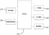
- FIG. 2is a block diagram of a self-mobile robot according to an embodiment of the present invention.
- FIG. 3is a schematic view of a first specific scheme of the first mechanical interface and the second mechanical interface of FIG. 2.
- FIG. 4is a schematic view showing the connection end and the mating end in the connected state of the solution of FIG. 3.
- Figure 5is a second specific schematic view of the first mechanical interface and the second mechanical interface of Figure 2.
- Figure 6is a schematic view showing the connection end and the mating end of the arrangement of Figure 5 in a connected state.
- Fig. 7is a schematic view showing the disconnected connection state of the connecting end and the mating end in the embodiment of Fig. 5.
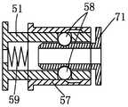
- Figure 8is a schematic view of a third embodiment of the first mechanical interface and the second mechanical interface of Figure 2.
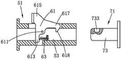
- Figure 9is a schematic view showing the connection end and the mating end of the arrangement of Figure 8 from the non-connected state to the connected state.
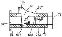
- Figure 10is a schematic view showing the connection end and the mating end of the arrangement of Figure 8 in a connected state.
- Figure 11is a schematic view showing the disconnected connection state of the connecting end and the mating end in the embodiment of Figure 8.
- FIG. 12is a schematic diagram of an automatic search and connection working module of a self-moving module according to an embodiment of the present invention.
- FIG. 13is a schematic diagram of a self-moving module automatically finding and connecting a working module according to another embodiment of the present invention.
- Figure 14is a schematic diagram of a self-mobile robot system of a second embodiment of the present invention.
- FIG. 15is a block diagram of the self-mobile robot of FIG. 14.
- Fig. 16is a front elevational view showing the flank of the self-moving robot of Fig. 14 in a folded state.
- Fig. 17is a front elevational view showing the state in which the flanking of the mobile robot of Fig. 16 is dropped.
- FIG. 18is a bottom plan view of the self-moving robot of FIG. 14.
- Figure 19is a schematic illustration of a smart lawn mower system in accordance with a third embodiment of the present invention.
- Figure 20is a schematic view of the intelligent lawn mower of the intelligent lawn mower system of Figure 19 in a liquid-spraying operation
- Figure 21is a block diagram of the intelligent lawn mower of Figure 20;
- Figure 22is a flow chart of the intelligent lawn mower spraying liquid of Figure 20.
- Detection unit 211RFID reader 213, image acquisition device
- Image identification 51connection end 71, mating end
- first arm 615first arm 615, second arm 617, third arm
- 201Intelligent lawn mower system; 202. ground; 204. docking station;
- the self-mobile robot systemincludes a self-mobile robot and a docking station 5.
- the self-moving robotincludes at least one of a self-moving module 1 and a plurality of work modules 3 that are interchangeably connected to the self-moving module 1. Since the mobile robot is automated to cruise and perform work in the work area 7, the stop station 5 is for parking from the mobile robot.
- the docking station 5is provided for the mobile robot to park when it is not in operation, and the docking station 5 is further provided with a working module 3 parking position for docking the plurality of working modules 3.
- the self-moving robotcan remove the work module 3, connect the work module 3 or replace the work module 3 in the docking station 5.
- the docking station 5is provided with a power interface for charging the mobile robot.
- the self-moving module 1includes a control unit 11, a first energy unit 13, a first traveling unit 15, and a first interface unit 17, and further includes a housing in which the aforementioned units are mounted.
- the specific physical form of the control unit 11is a control circuit board in which one or more processors, memories, other related components, and corresponding peripheral circuits are disposed.
- the control unithas a built-in control program to execute predetermined commands, control the operation of the mobile robot, cruise and work in the work area 7, and return to the work station 3 required to replenish energy and connect the stop station 5.
- the first energy unit 13includes a rechargeable battery pack, and the first energy unit 13 supplies energy to the self-moving module 1 or from the mobile robot.
- the first traveling unit 15includes a traveling motor and a traveling member, and the traveling motor drives the traveling member to move relative to the ground, thereby driving the self-moving module 1 or walking from the mobile robot relative to the ground.
- the traveling motoris set to one or more, and the traveling components are well-known structures in the industry such as a wheel set and a crawler belt, and details are not described herein.
- the self-moving module 1includes a second work unit 19 for performing a particular type of work, such as mowing work. In one embodiment, the self-moving module 1 does not have a second working unit 19.
- the work module 3has a number of different types, and a particular type of work module 3 performs a specific work task. For example, if the type of the working module 3 is a mowing module, the working module 3 performs a mowing work; if it is a snow sweeping module, the working module 3 performs a snow cleaning work; if it is a leaf collecting module, the working module 3 performs Fragment collection work; if it is a blower module, the work module 3 performs a blower work, and the like, and is not exemplified.
- a variety of different types of work modules 3are interchangeably connected to the aforementioned self-moving module 1.
- the work module 3includes a first work unit 39, a second travel unit 35, and a second interface unit 37, and further includes a housing in which the aforementioned respective units are mounted.
- the first work unit 39performs the aforementioned specific work tasks,
- the specific structurediffers depending on the type of the work module 3, that is, it varies depending on the work task.
- the first working unit 39 of the mowing moduleis a mowing work head, and the mowing work head comprises at least a mowing blade;
- the first working unit 39 of the snow sweeping moduleis a snow cleaning working head;
- the first working unit of the leaf collecting module 39is a leaf collecting unit, the collecting unit includes at least a suction assembly for sucking the broken leaves and a collecting chamber for storing the broken leaves, the suction assembly comprising a suction tube and a rotatable blade forming a negative pressure at the suction nozzle;
- the first working unit 39 of the moduleis a blowing unit, and includes at least a blowing unit, a blowing unit, a specific blowing tube, and a blade for forming an outward airflow at the blowing nozzle.
- the first working unit 39 of the working module 3includes a working motor to output the power required for operation; in another alternative embodiment, the first working unit 39 does not include a working motor, and The motor is shared with the working module 3 or other units of
- the second walking unit 35includes a running member that is driven to move relative to the ground to drive the self-moving module or the self-moving robot to walk relative to the ground.
- the traveling componentsare well-known structures in the industry such as wheel sets and crawlers, and will not be described in detail.
- the second travel unit 35further includes a travel motor that drives the travel component to move.
- the second traveling unit 35does not include a traveling motor, and the traveling member is only a follower such as a driven wheel or the like, and is driven by the moving module 3 to assist the working module 3 to move.
- the working module 3comprises a second energy unit 33 comprising a rechargeable battery pack, the second energy unit 33 providing energy to the working module 3 or from the mobile robot.
- the control unit 11monitors the energy levels of the first energy unit 13 and the second energy unit 33, and controls the second energy unit 33 to the working module 3 when the energy level of the second energy unit 13 is greater than the first threshold. Energy is provided; when the energy level of the second energy unit 33 is less than the first threshold and the energy level of the first energy unit 13 is greater than the second threshold, the first energy unit 13 is controlled to provide energy to the working module 3.
- the working module 3may not include the second energy unit 33, and the energy required for the working module 3 to operate is derived from the self-moving module 1.
- the first interface unit 17 of the mobile module 1 and the second interface unit 37 of the working module 3can be mated to connect the working module 3 to the self-moving module 1.
- the first interface unit 17includes a first mechanical interface 175, a first control interface 173, and a first energy interface 171;
- the second interface unit 37is correspondingly provided with a second mechanical interface 375, a second control interface 373, and a second energy interface. 371.
- the first interface unit 17 and the second interface unit 37are connected, the first mechanical interface 175 and the second machine The mechanical interface 375 is connected, the first energy interface 171 is connected to the second energy interface 371, and the first control interface 173 is connected to the second control interface 373.
- the first mechanical interface 175 and the second mechanical interface 375are connected for connecting the optional interlocks of the self-moving module 1 and the working module 3 together for common movement.
- the first control interface 173 and the second control interface 373are connected to implement signal transmission between the self-moving module and the working module, so that the self-moving module 1 can control the working module 3 to work through the first control interface 173 and the second control interface 373.
- the working module 3can feed back various operating parameters and environmental information to the self-moving module 1.
- the first energy interface 171 and the second energy interface 371are connected for realizing energy transfer between the self-moving module 1 and the working module 3, for example, transferring energy from the moving module 1 to the working module 3, or conversely, the working module 3 is self-contained
- the mobile module 1delivers energy.
- the working module 3receives charging energy by connecting to the external power interface from the mobile module 1. That is, the charging interface of the mobile module 1 is connected to the power interface to receive the charging power, and then at least part of the charging power is transmitted to the second energy unit 33 of the working module 3 through the first energy interface 171 and the second energy interface 371.
- the charging interface of the self-moving moduleincludes a first charging pole set and a second charging pole set, the first charging pole set being connected to the first energy unit 13 to Charging, the second charging pole piece group is connected to the second energy unit 33 through the first energy interface 171 and the second energy interface 373 to charge it.
- the charging interface of the self-moving moduleincludes only one set of charging pole pieces, the charging pole piece group is connected to the first energy unit 13 to charge thereto, and can pass the first energy The interface 171, the second energy interface 373 is connected to the second energy unit 33 to charge it.
- the working module 3is directly connected to an external power interface to receive charging energy. That is, the working module 3 has a charging interface and a power interface.
- the charging interface and the external power interfacecan both be wireless charging interfaces. Since it is not necessary to equip each working module 3 with a dedicated charging position and charging line, the wireless charging interface scheme can greatly reduce the charging cost when multiple working modules 3 are present at the same time.
- the working module 3can function as both charging by the self-moving module and direct connection to the external power interface.
- the working module 3has a separate charging interface and a second energy interface 371 for directly connecting the power interface and connecting the first energy interface 171.
- the working module 3can only have a second energy interface 371, and the second energy interface 371 can be connected to the first energy interface 171. To directly connect to an external power connector.
- the first mechanical interface 175includes at least one connecting end 51
- the second mechanical interface 375includes at least one mating end 71.
- the connecting end 51 and the mating end 71are in one-to-one correspondence. The same amount.
- the connecting end 51includes a receiving hole 53.
- the mating end 71includes a latching pin 73.
- the receiving hole 53is shaped to receive the latching pin 73.
- An electromagnet 55is disposed in the receiving hole, preferably at the bottom of the receiving hole.
- the electromagnet 55After the energization, the electromagnet 55 generates a magnetic force.
- a material that can be attracted to the electromagnet 55is disposed on the plug 73, preferably at the top of the plug.
- Itis a permanent magnet 75.
- the latch 73is inserted into the receiving hole 53, the permanent magnet 75 and the electromagnet 55 are also in contact with each other, and by changing the magnetic pole direction of the electromagnet 55, the magnetic poles of the two end portions that are in contact with each other are opposite or the same.
- the self-moving modulecan connect or unload the working module 3 by controlling the magnetic pole direction of the electromagnet 55.
- the magnetic pole direction of the electromagnet 55can also be fixed, and the two end magnetic poles that are always in contact with each other are opposite when energized, and the connection or the corresponding connection is made by selectively energizing or de-energizing the electromagnet 55 or Uninstall the work module.
- the number of the connecting end 51 and the mating end 71are two, which can be matched one by one to achieve better connection stability.
- the specific arrangement of the connecting end 51 and the mating end 71 in Figures 3 and 4is merely exemplary, and there are many variations in its concept.
- the arrangement positions of the electromagnet 55 and the permanent magnet 75are interchanged, or the receiving hole 53 is disposed on the second mechanical interface 375 and the plug 73 is disposed on the first mechanical interface 175.
- the receiving hole 53is designed as a tapered hole, and the plug 73 is designed to be tapered.
- the receiving hole 53 and the latch 73are eliminated, and they are directly connected to each other by electromagnetic force.
- the first mechanical interface 175includes at least one connecting end 51
- the second mechanical interface 375includes at least one mating end 71
- the connecting end 51 and The mating ends 71are in one-to-one correspondence and the same number.
- the connecting end 51includes a receiving hole 53
- the mating end 71includes a latch 73.
- the present embodimentis not connected to the self-moving module 1 and the working module 3 by electromagnetic force, but is connected to the self-moving module 1 and the working module 3 through a card slot matching structure.
- the side wall of the receiving hole 53has a plurality of through holes, and each of the through holes is detachably received with a card ball 58.
- the diameter of the card ball 58is slightly larger than the thickness of the through hole, and can be along the through hole. Move through the direction of the through.
- a sliding sleeve 57is sleeved on the side wall of the receiving hole 53.
- a plurality of receiving slots 571are disposed on the sliding sleeve 57 corresponding to the position of the through hole.
- the card 58can be partially received in the receiving slot 571 and enters
- the receiving groove 571can be detached from the receiving hole, and can be detached from the receiving groove 571 when entering the receiving hole 53.
- the sliding sleeve 57can move back and forth along the side wall of the receiving hole 53, and a spring 59 abuts against the sliding sleeve 57, so that the receiving groove 571 is separated from the through hole.
- the side wall of the latch 73is provided with a card slot 731 having the same number of through holes.
- the latch 73enters the receiving hole 53 , the card ball 53 falls into the receiving hole 53 and is caught in the slot 731 , and the spring 59 forces the sliding sleeve 57 to be located at the position where the receiving slot 571 is away from the through hole.
- the side wall of the sliding sleeve 57presses the card ball 58 into the card slot 731, thereby realizing the interlocking connection of the connecting end 51 and the mating end 71, thereby realizing the interlocking connection of the self-moving module 1 and the working module 3.
- the sliding sleeveis driven to overcome the force of the spring 59, the receiving groove 571 and the through hole are aligned, and the sliding sleeve 57 is in the unlocking position.
- the card ball 58is pushed into the receiving groove 571 and away from the receiving hole 53, and the interlocking connection between the moving module 1 and the working module 3 is released.
- the establishing connection and the disconnection of the self-moving module 1 and the working module 3may be automatic.
- a permanent magnetmay be disposed on the sliding sleeve 57, and an electromagnet is disposed from the matching position on the moving module 1.
- the electromagnet attracting sliding sleeve 57When disconnected, similarly, the electromagnet attracting sliding sleeve 57 is moved to the unlocking position, and after the moving module 1 is moved away from the connection, the electromagnet is de-energized, and the sliding sleeve 57 is restored to the locked position.
- the first mechanical interface 175includes at least one connecting end 51
- the second mechanical interface 375includes at least one mating end 71, connected
- the end 51 and the mating end 71are in one-to-one correspondence and the same number.
- the connecting end 51includes a receiving hole 53.
- the mating end 71includes a latching pin 73.
- the receiving hole 53is shaped to receive the latching pin 73.
- the connecting end 71is provided with a pivotable latching member 61.
- the latching member 61is disposed through the side wall of the receiving hole 53 of the portion, and has a first rotating arm 613, one The second arm 615, a third arm 617, and a pivot shaft 611 between the arms.
- the first rotating arm and the third rotating armare at least partially located in the receiving hole, the first rotating arm is connected with the elastic member 63, and the third rotating arm end is provided with a hook 618.
- the second rotating arm 615is located outside the receiving hole 53.
- the elastic member 63biases the first rotating arm 613 in a direction in which the third rotating arm is in a latching position.
- the hook 618is at least partially located inside the inner wall of the receiving hole 53.
- the elastic member 63includes a spring seat and a spring, one end of the spring is mounted on The spring seat has the other end connected to the first rotating arm 613.
- the latch 73is provided with a bayonet 733 which mates with the aforementioned hook 618.
- the first rotating arm 613, the elastic member 63, and the pivoting shaft 611are substantially located in the receiving hole 53, and the hook 618 forms a slope toward the side wall of the receiving hole 53.
- the end of the latch 73presses the slope of the hook 618 to cause the hook 618 to move from the latched position to the unlocked position against the biasing force of the elastic member 63.
- the hook 618In the unlocked position, the hook 618 completely leaves the inner wall of the receiving hole 53, and then the latch 73 Continue to insert the receiving hole 53 until the bayonet 733 advances to the position where the hook 618 is located. At this time, the elastic member 63 presses the hook 618 to return to the latching position, and the hook 618 and the bayonet 733 are locked, thereby the self-moving module 1 and The working modules 3 are connected together.
- the second rotating arm 615is located substantially outside the receiving hole 53.
- the second rotating arm 615is only required to be overcome against the biasing force of the elastic member 63, and the hook 618 is pulled from the bayonet.
- the working module 3can be removed.
- the establishing connection and the disconnection of the self-moving module 1 and the working module 3may be automatic.
- a permanent magnetmay be disposed on the second rotating arm 615, and an electromagnet is disposed from the matching position on the moving module 1.
- the self-moving module 1energizes the electromagnet, and attracts the second rotating arm 615 to move the unlocking position against the spring force.
- the electromagnetis powered off from the moving module 1, and the latching member 61 bounces back, and the hook 618 Hook the bayonet 733 to establish an interlocking connection.
- the electromagnetattracts the second arm 615 to the unlocked position.
- the electromagnetis de-energized and the second arm 615 returns to the locked position.
- the number of the connecting end 51 and the mating end 71are two, which can be matched one by one to achieve better connection stability.
- the positions of the first control interface 173 and the second control interface 373are respectively correspondingly arranged, so that when the first mechanical interface 175 and the second mechanical interface 375 are successfully docked, the first control interface 173 and the second control interface 373 are also docked at the same time. . Since the first mechanical interface 175 and the second mechanical interface 375 already have a latching function, the first control interface 173 and the second control interface 373 may not be provided with a latching function related structure, and may be simply inserted and removed with each other.
- the first control interface 173 and the second control interface 373may be a wired communication structure or a wireless communication structure, and can implement signal transmission.
- the positions of the first energy interface 171 and the second energy interface 371are respectively correspondingly arranged, so that when the first mechanical interface 175 and the second mechanical interface 375 are successfully docked, the first energy interface 171 and the second energy interface 371 are also docked at the same time. . Since the first mechanical interface 175 and the second mechanical interface 375 already have a latching function, the first energy interface 171 and the second energy interface 371 may not be provided with a latching function related structure, and may be simply inserted and removed with each other. The energy interface is used to transfer energy between the mobile module 1 and the working module 3. The specific structure and implementation principle are well known to those skilled in the art, and are not described herein again.
- the self-moving module 1drives the working module 3 to cruise in the working area 7 through the connection of the first mechanical interface 175 and the second mechanical interface 375, and passes through the first control interface.
- the connection control work module 3 of the 173 and the second control interfaceperforms a specific work.
- electrical energycan also be transferred between the self-moving module 1 and the working module 3 through the first energy interface 171 and the second energy interface 371.
- the self-moving module 1automatically interfaces with a specific working module 3 according to a preset program, and automatically cruises and performs a specific work task in the work area 7.
- the self-moving module 1has a detecting unit to detect the target working module 3 to be sought.
- the detecting unit 21detects the working module 3 and transmits the detection result to the control unit 11.
- the control unit 11determines whether the working module 3 to be connected is detected according to the detection result. When the determination result is YES, the control unit 11 controls the first walking unit 15 to walk to make the self-moving module 1 and the working module to be connected. 3 connections.
- the detecting unit 21is an RFID reader 211
- the working module 3is provided with an RFID tag 411, and the contents of the RFID tag 411 on different working modules 3 are different.
- the RFID reader 211can read its RFID tag 211, and the control unit 11 knows the working module 3 that is currently approaching according to the detection result sent by the RFID reader.
- the specific typewhen the self-moving module recognizes that the current working module 3 is the type it is looking for, enters the docking program, docks the first interface unit 17 and the second interface unit 37, and connects the target working module 3 to the self. Move module 1.
- the self-moving module 11travels in the docking direction, and the docking direction is a direction in which the first interface unit 17 and the second interface unit 37 are aligned with each other.
- the self-moving module 1can correspondingly determine the approximate orientation and distance of the target working module 3 when the specific RFID tag is recognized, and the self-moving module 1 is based on The estimated information adjusts its orientation to the docking direction, and moves the direction in which the first interface unit 17 and the second interface unit 37 are brought close to each other and connected to each other to achieve docking.
- the self-moving module 1travels in the docking direction by identifying the guiding unit 43 in the docking station 3, which may be a guide wire, a magnetic strip or the like carrying a specific electrical signal, along which the guiding unit 43 Arranged in the docking direction, the self-moving module 1 uses the corresponding guiding sensing unit to identify the guiding line and the magnetic strip.
- the mooring position of the working module 3is provided with guide rails that will guide the moving module 1 into the exact docking direction to assist in its docking.
- the guide railmay be a narrow eight-shaped guide side edge in the outer width, and the wheel of the moving module 1 enters the guide rail and is restrained by the side edge to gradually enter the accurate docking direction; the guide rail may also be a guide groove arranged in a width equal to the wheel. The slot will be guided from the mobile module to the exact docking direction.
- the foregoing manners of confirming the docking directionmay be combined and used in various combinations and combinations to increase the docking accuracy, such as the direction estimation of the RFID tag and the arrangement of the guiding unit 43 and the like, and details are not described herein.
- the self-moving module 1monitors whether the docking is successful, and if the docking succeeds, the docking program is exited, and the working program or other programs are entered.
- the manner of monitoring whether the docking is successfulis to monitor whether a specific voltage, current or signal appears at the first control interface 173 or the first energy interface 171, and details are not described herein.
- the self-moving robotleaves the docking station 5, cruising and performing a specific work task in the work area 7.
- the self-moving robotalso brings the connected working module 3 back to the charging station according to an external command or its own plan, and is detached from the working module 3.
- the self-moving robotfirst returns to the docking station 5, and the returning method has been disclosed in the prior art, such as regression along the boundary line, etc., and will not be described again. After returning to the stop station 5, the connection from the mobile module 1 and the work module 3 is disconnected from the mobile robot.
- the self-moving robotdisengages the connection between the mobile module 1 and the working module 3 after the working module 3 is placed in the docking direction, and the docking direction is as described above, and can be confirmed by the guide rail or the guide line. .
- the parking positionThere are a plurality of parking positions and there is no one-to-one correspondence between the working modules 3, and the working module 3 can be placed in any empty parking position at will; in another embodiment, the parking position There is a one-to-one correspondence between the working module 3 and the working module 3, and the mobile robot 1 is disconnected from the mobile module 1 and the working module 3 after the working module 3 is placed in a specific corresponding parking position.
- the manner of disconnecting the connectiondiffers depending on the type of connection. For example, in the electromagnetic force docking method described above, the self-moving module 1 realizes the disconnection by cancelling the electromagnetic force on the electromagnet.
- the detecting unit 21is an image collecting device 213, and the working module 3 is provided with a specific image identifier 413, and the contents of the image identifier 413 on different working modules 3 are different.
- the image identification 413may be a two-dimensional code, a barcode, or other standardized pattern, and the image identification 413 may also be in other forms such as a combination of specific colors or a specific shape or the like.
- the self-moving module 1simultaneously performs pattern acquisition and recognition when approaching each working module 3, and when identifying a specific image identifier 413 corresponding to the target working module 3, such as a specific two-dimensional code, barcode or other pattern, it is judged to carry the
- the working module 3 of the image identificationis the target working module 3, and then enters the docking program, docks the first interface unit 17 and the second interface unit 37, and connects the target working module 3 to the self-moving module 1.
- the self-moving module 1also travels in the docking direction. Specifically, according to the size of the identified image identifier 413, the arrangement manner of the image identifier 413, and the like, the self-moving module 1 can estimate the approximate orientation and distance of the target working module 3 when the specific image identifier 413 is recognized.
- the mobile module 1adjusts its own orientation to the docking direction according to the estimated information, and moves the direction in which the first interface unit 17 and the second interface unit 37 are brought close to each other and connected to each other to achieve docking.
- the self-moving module 1facilitates travel in the docking direction by identifying the guiding unit 43 in the docking station 5, or assists docking by rails.
- the specific methodis the same as before and will not be described again.
- the foregoing various ways of confirming the docking directioncan be combined and used in various combinations and combinations to increase the docking accuracy.
- the self-moving module 1monitors whether the docking is successful, and the specific manner is the same as before, and will not be described again.
- the self-moving robotalso brings the connected working module 3 back to the charging station according to an external command or its own plan, and is detached from the working module 3.
- the specific methodis the same as before and will not be described again.
- the detecting unitis an image collecting device. Unlike the previous embodiment, there is no specific image identifier on the working module 3, and the moving module 1 recognizes the shape of the working module 3 itself. Color, texture, or a combination thereof to determine whether it is the target work module 3.
- the self-moving module 1also has a detecting unit 23, but unlike the foregoing various embodiments, the detecting unit 23 identifies a feature or logo in the external environment in which the working module 3 has a corresponding relationship, instead of directly recognizing The feature or work module identification on the work module 3.
- each specific working module 3is docked at a specific parking position of the docking station 5, and a working module identifier corresponding to the specific working module 3 is provided at the specific parking position.
- the mobile module 1is looking for a specific target working module 3, it only needs to find a working module located at a specific location corresponding to the target working module 3.
- the target working module 3can be located, then transferred to the docking program, the first interface unit 17 and the second interface unit 37 are docked, and the target working module 3 is connected to the self-moving module 1.
- the detecting unit 23also identifies the feature or the working module identifier on the working module 3, and the specific implementation and the corresponding setting on the working module 3 are as described in the previous embodiment, and are no longer Narration.
- the docking station 5has a plurality of parking locations, each of which is used to park different specific working modules 3, each having a respective specific RFID tag 411.
- the detecting unit 23 on the self-moving module 1is an RFID reader 211.
- the self-moving module 1can read its RFID tag 211 when it is close to each working module 3, and then know the specific type of the working module 3 that is currently approaching, when the current working module is recognized by the mobile module 1 3 is the type it is looking for, then enters the docking program, docks the first interface unit 17 and the second interface unit 37, and connects the target working module 3 to the self-moving module 1.
- the docking station 5has a plurality of parking positions to park different specific working modules 3, except that the detecting unit 23 is an image collecting device.
- a specific image identifier 413is provided at the parking position, and the content of the image identifier 413 on the parking space where the specific working module 3 is located is different.
- the image identification 413may be a two-dimensional code, a barcode, or other standardized pattern, and the image identification may also be in other forms such as a combination of specific colors or a specific shape.
- the image identification 413may be located on the bottom surface at the entrance of the parking position, or may be located on the rear wall or the side wall of the parking space, and may of course be other suitable locations for the image acquisition device 213 to recognize.
- the self-moving module 1performs pattern acquisition and recognition when approaching each working module 3, and when the specific image identifier 413 corresponding to the target working module 3 is recognized, such as a specific two-dimensional code, barcode or other pattern, it is judged to carry the image.
- the working module of the identifier 413is the target working module 3, and then enters the docking program, docks the first interface unit 17 and the second interface unit 37, and connects the target working module 3 to the self-moving module 1.
- the docking station 5has a plurality of parking positions to park different specific working modules 3, except that the work identification at the parking position has both a guiding self-moving module and a working module. Docking boot logo.
- the guiding identifieris a guiding line carrying an electrical signal, and electrical signals corresponding to different guiding lines of the specific working module 3 are different, for example, different current frequencies, or different electrical signal waveforms carried, etc. Wait, no longer repeat them.
- the packet corresponding to the detecting unit 23Inductance of the electromagnetic signal generated by the induction guide line in the environment.
- the guiding lineis arranged on the bottom surface of the parking position and extends outside the parking position. After the mobile module 1 recognizes the electrical signal corresponding to the target working module 3, the walking along the guiding line where the electrical signal is generated can be accurately approached in the parking position.
- the target working module 3, and the guiding lineis arranged to correspond to the docking trajectory, and can be accurately docked with the working module 3 as long as the moving module 1 walks along the guiding line. Walking along the guide line can walk across the guide line or at a distance from the guide line.
- the docking station 5has a plurality of parking positions to park different specific working modules 3, and the specific identification at the parking position is a guiding identifier that simultaneously guides the docking of the mobile module 1 and the working module 3. .
- the guiding identifieris a magnetic track
- different specific working moduleshave different magnetic track parameters, such as different magnetic field strengths
- the detecting unit 23corresponds to a magnetic induction sensor for identifying the magnetic track.
- the self-mobile robothas a set working period and a non-working period.
- the self-moving robotperforms various types of work tasks and automatically returns to the docking station 5 after the energy is exhausted, and the self-moving robot does not work during the non-working period. , docked at the stop 5 .
- the usercan set the working hours from 8:00 to 18:00 Monday to Friday, and the other hours are non-working hours.
- the self-moving module 1sequentially carries the respective working modules 3 to operate according to the set timing. For example, when each working module 3 includes a mowing module, a fertilizing module and a sprinkling module, the self-moving module 3 first connects the mowing module for 3 hours of mowing work, and then connects the fertilizing module for 3 hours of fertilization work, and finally connects the sprinkling module. 3 hours of watering work. During mowing work, the self-moving module 1 and the mowing module periodically enter the work area to cut the lawn and return to the charging station to replenish energy, as well as during fertilization and watering.
- the self-mobile robot system of FIG. 14includes a self-mobile robot 101 and a docking station 5. From the mobile robot automation, the work area 103 is cruised and performs work, and the stop station 5 is provided for parking from the mobile robot.
- the work area 103includes a grassland 131 and a road surface 133.
- the grass 131has a turf above it. There is no turf above the road surface 133 for people and vehicles to walk.
- the road surface 133includes not only a narrow path but also a wide non-stop or activity. Grass areas, such as courtyards without grass, stadiums, etc.
- the self-mobile robot systemfurther includes a virtual boundary, such as around the work area 3 arranging boundary wires, infrared walls, RFI D tags, etc.; in one embodiment, the virtual boundary divides the work area 3 into a plurality of sub-areas, such as at least one grass area and at least one road area.
- a virtual boundarysuch as around the work area 3 arranging boundary wires, infrared walls, RFI D tags, etc.; in one embodiment, the virtual boundary divides the work area 3 into a plurality of sub-areas, such as at least one grass area and at least one road area.
- the docking station 5is provided for parking from the mobile robot 101 when not in operation.
- the docking station 5is provided with a power interface that is charged from the mobile robot 101.
- the self-mobile robot 101includes a control module 111, an energy module 113, a drive module 115, a mowing module 117, and a cleaning module 119, and further includes a housing in which the aforementioned units are mounted.
- the specific physical form of the control module 111is a control circuit board in which one or more processors, memories, other related components, and corresponding peripheral circuits are disposed.
- the control unithas a built-in control program to execute predetermined commands, control operation from the mobile robot 101, cruise and work in the work area 103, return to the stop station 5, and the like.
- the energy module 113provides working energy to the mobile robot 101, and may be a suitable energy storage material such as a rechargeable battery pack, a solar energy storage device, or the like.
- the driving module 115drives the mobile robot 101 to move on the ground, usually including a wheel set, and may also include a crawler belt, a mechanical foot, etc.; the driving module 115 may include a dedicated power source, such as a driving motor, etc., and may also share a power source with other modules. .
- the mowing module 117is used to perform a mowing work, including a cutting element such as a cutter head, a knife blade or a mowing rope carrying a rake blade; the mowing module 117 may include a dedicated power source such as a cutting motor, etc., and other modules. Shared power source.
- the cleaning module 119is used to perform ground cleaning work, such as sweeping, vacuuming, blowing leaves, sucking leaves, etc.; the cleaning module 119 may include a floor cleaning module, a suction module, a blowing module or a blowing module, etc.; the cleaning module 119 may include a dedicated Power sources, such as cleaning motors, can also share power sources with other modules.
- the self-mobile robot 101has a mowing mode and a cleaning mode.
- the self-mobile robot 101can automatically cruise on the grass 131 and perform a mowing work.
- the cleaning modethe self-mobile robot 1 can automatically cruise and perform cleaning. jobs.
- the mowing workis performed, the mowing module of the mobile robot 101 is started, and the cleaning module is stopped; otherwise, when the cleaning work is performed, the mowing module is stopped and the cleaning module is started.
- the self-moving robotperforms the cleaning work only on the grass; in other embodiments, the self-moving robot performs the cleaning work only on the road surface; in other implementations
- the cleaning robotperforms cleaning work on the grass and the road surface; in other embodiments, the self-moving robot can selectively perform cleaning work only on the grass, or only on the road surface, or on the grass and the road surface.
- the cleaning modulemainly performs the road sweeping work
- the self-moving robotperforms the cleaning work only on the road surface in the cleaning mode; The cleaning robot performs cleaning work on the road surface and on the grass when the leaf removal work is mainly performed and the fallen leaves are scattered on the grass.
- the self-mobile robot 101further includes a ground recognition unit 121 to identify that the type of the ground is a grass or a road surface.
- the ground recognition unit 121transmits the recognition result of the target area to the control module 111, and the control module 111 controls the self-mobile robot from the mowing mode. Switch to clean mode, ie the mowing module stops and the cleaning module starts.
- the ground recognition unit 121transmits its target recognition result to the control module 111, and the control module 111 controls the self-mobile robot to switch from the cleaning mode to the mowing mode, that is, the cleaning module. Stop and mowing the module to start.
- the ground recognition unit 121includes a camera and an identification component coupled to the camera.
- the cameracaptures the ground image of the target area and transmits it to the identification component.
- the identification componentis preset with a ground type determination algorithm, and the recognition component extracts the image feature and inputs it into the ground type algorithm to determine that the target area is grass or road surface.
- the image featuresmay vary according to the ground type determination algorithm.
- the image featureincludes a color pixel value of the image of the target area, and the ground type algorithm forms a color distribution map of the acquired pixel value, and compares the peak area with the largest color area in the distribution map with the preset area value.
- the ground preset algorithmmay also employ other image-based grass recognition algorithms, which will not be explained here.
- the ground recognition unit 121includes a ground hardness sensor and an identification element coupled to the ground hardness sensor.
- the ground hardness sensorcollects the ground hardness information of the target area and transmits it to the identification component.
- the identification componentis preset with a ground type judgment algorithm, and the identification component inputs the ground hardness information into the ground type algorithm to determine that the target area is grass or road surface.
- the ground hardness sensorcan be placed at different locations from the mobile robot.
- the ground hardness sensormay be disposed on the wheel of the self-moving robot for detecting the ground hardness value in real time. In other embodiments, the ground hardness sensor can also be disposed on the housing of the self-mobile robot.
- the ground type judging algorithmjudges the ground type of the target area according to the ground hardness value given by the ground hardness sensor. When the local surface hardness value is greater than the learned value equals the preset value, the target area is judged as the road surface, otherwise the target area is determined as the grassland.
- the ground preset algorithmmay also use other hardness based signals. Pavement recognition algorithm.
- the ground hardness sensormay also be disposed at the junction of the grassland 131 and the road surface 133.
- the ground hardness sensormay transmit a notification signal to the self-mobile robot when the mobile robot approaches the junction of the grass 131 and the road surface 133.
- the ground type segmentation algorithmdetermines whether the mobile robot enters the grassland or enters the road surface according to the difference of the received notification signal.
- control module 111further includes a mode control unit.
- the mode control unitcontrols the self-moving robot to switch between the mowing mode and the cleaning mode according to a preset program.
- the mode control unitassigns the time from when the mobile robot is in the mowing mode and the time in the cleaning mode based on the date or season information.
- the preset programmay store a time ratio table of the mowing mode and the cleaning mode of the mobile robot according to the growth rule of the grass in each region of the world in a year, and the rules may be obtained by meteorological statistical data. know. For example, grass in China has the fastest growth rate in summer, followed by spring and autumn, and the slowest growth of winter grass.
- the time ratio in the preset programis shown in Table 1:
- the table onegives the percentage data of an embodiment, the specific time ratio of the mowing mode and the cleaning mode in a specific time, and the user can set according to his own location or his own preference.
- the cleaning module 119is a leaf cleaning module.
- the leaf cleaning moduleis a blower module or a suction module or a sweeping module.
- the cleaning module 119can be located below or to the side of the housing of the mobile robot.
- a movable side flap 12is provided on the side of the housing of the mobile robot 101, and a cleaning module 119 is mounted on the side flap 12.
- FIG. 16when in the mowing mode, the side flaps 12 are folded against the side of the housing; as shown in FIG. 17, when in the cleaning mode, the side flaps 12 are dropped, and the cleaning module operates under the driving of the driving module. .
- the cleaning module 119is a blowing module.
- the air blowing modulemay include a fan 1191, and the fan moves the airflow to blow off or blow up the piles of garbage such as leaves or dust scattered on the road surface.
- the blowing moduleincludes a fan 1191 and a duct 1193 communicating with the fan 1191.
- the fan 1191is located below the housing of the mobile robot 101.
- the driving moduledrives the fan 1191 to generate airflow, and the airflow is blown to the road surface through the air duct 1193.
- the garbagesuch as fallen leaves or dust around the air passage is blown off or blown up.
- the blower modulecan also be displaced from the side of the housing of the mobile robot.
- the cleaning module 119is a suction module.
- the suction moduleincludes a fan, a duct and a dust collecting device, and the airflow generated by the fan is used to suck the garbage such as leaves or dust on the road surface into the dust collecting device.
- the suction modulecan be located below the housing of the mobile robot or on the side of the housing. In an embodiment, the suction module may not include a dust collecting device, and garbage collected such as leaves or dust is directly discharged through the dust exhaust port.
- the cleaning module 119is a floor cleaning module.
- the sweeping modulecan be a sweeping brush or a sweeping roller.
- the sweeping modulecan be displaced from below the housing of the mobile robot or on the side of the housing.
- the sweeping moduleis located below the housing.
- the cleaning module 119is detachably mounted to the housing. When the cleaning module is damaged or dirty, the user can remove it for replacement or cleaning.
- the detachable structureincludes common fastener connection structures such as bolt and nut connections, screw connections, etc.; the detachable structure also includes fastenerless connections, such as snap-fit connections, and shape connections.
- the present inventionis not limited to the specific embodiment structures, and the structures based on the inventive concept are all within the scope of the present invention.
- FIG. 19shows a self-mobile robot system according to an embodiment of the present invention, in particular, an intelligent lawn mower system 201, which is disposed on the ground 202.
- the ground 202is divided into a work area (not shown) and a non-work area (not shown), and a boundary line between the work area and the non-work area forms a boundary.
- the intelligent lawn mower system 201includes a docking station 204 and a smart lawn mower 210 for automatically walking and mowing on the ground 202, the docking station 204 generally being disposed on a peripheral boundary of the work area.
- FIG. 20is a schematic diagram of the intelligent lawn mower 210 in a state of sprinkling
- FIG. 21is a block diagram of the intelligent lawn mower of FIG.
- the intelligent lawn mower 210includes a housing 212, a housing 212 that is hollow to form a receiving cavity, a controller 214 installed in the receiving cavity to control the intelligent lawn mower 210 to automatically walk and mowing, and a sprinkler controlled by the controller 214 for spraying work.
- Liquid device 216Liquid device 216.
- the intelligent lawn mower 210further includes a working module 218, a walking module 220, and an energy module 222.
- the controller 214is connected to the sprinkling device 216, the working module 218, the walking module 220, and the energy module 222.
- Work module 218is used to perform specific tasks.
- the working module 218is specifically a cutting module including a cutting member (not shown) for performing a cutting operation and a cutting motor (not shown) for driving the cutting member.
- the housing 212includes a housing bottom portion 2122 and an opposite housing top portion 2121. The cutting member is mounted to the housing bottom portion 2122, and the cutting motor is mounted in the housing 212 housing cavity.
- the walking module 220includes a wheel set 2201 for driving the intelligent lawn mower 210 to travel and a traveling motor (not shown) for driving the wheel set 2201.
- the wheel set 2201is mounted on the bottom portion 2122 of the housing, and the traveling motor is mounted in the housing cavity of the housing 212.
- the wheel setincludes a drive wheel driven by a travel motor and an auxiliary wheel that assists the support housing.
- the number of drive wheelscan be one, two or more.
- the energy module 222is used to power the operation of the intelligent lawn mower 210.
- the energy source of the energy module 222may be gasoline, a battery pack, etc., and in this embodiment the energy module 222 includes a rechargeable battery pack (not shown) disposed within the housing 212.
- the battery packreleases electrical energy to maintain the smart mower 210 in operation.
- the batterycan be connected to an external power source to supplement the power.
- the controller 214detects that the battery is low, the smart mower 210 will find the docking station 204 to charge itself to supplement the power.
- the sprinkler device 216is controlled by the controller 214 and can perform a sprinkling operation autonomously.
- the sprinkling device 216includes a liquid tank 2161 and a pipe communicating with the liquid tank 2161.
- the liquid tank 2161is installed in the receiving cavity for holding the liquid; one end of the pipe communicates with the liquid tank 2161, and the other end extends from the receiving cavity to the outside of the housing 212.
- the controller 214is used to control the liquid in the tank 2161 to enter and exit the pipeline.
- the liquidhere can be water, liquid fertilizer or pesticides.
- the ductincludes a first duct 2163 for influent and a second duct 2165 for sprinkling, the first duct 2163 is in communication with the tank 2161 at one end and extends from the rear of the casing 212 at the other end; One end of the pipe 2165 communicates with the liquid tank 2161, and the other end extends from above the casing 212.
- the intelligent lawn mower 210further includes a liquid amount monitoring module 224 for monitoring the liquid content in the liquid tank 2161, and the liquid
- the content information of the liquid in the tank 2161is converted into an electric signal recognizable by the controller 214 to the controller 214, and the controller 214 determines whether it is necessary to replenish the liquid tank 2161 based on the content of the liquid.
- the docking station 204is connected to a supply pipe 226 for replenishing the liquid tank 2161 of the sprinkling device 216.
- the controller 214detects that it is necessary to replenish the liquid tank 2161, the controller 214 controls the intelligent lawn mower 210 to return to the stopping station 204, at which time the first pipe 2163 is docked with the liquid supply pipe 226, and the controller 214 opens the first conduit 2163, and the water in the supply conduit 226 enters the tank 2161 through the first conduit 2163.
- the liquid amount monitoring module 224detects the liquid content in the liquid tank 2161 in real time, and when the liquid content in the liquid tank 2161 is in the preset liquid amount range, the controller 214 controls The intelligent lawn mower 210 continues to perform the liquid discharging operation; and when the liquid content is lower than the preset liquid amount range, the controller 214 controls the liquid discharging device 216 to stop the liquid discharging, and at the same time, the controller 214 controls the walking module 220 to make the smart The lawn mower 210 returns to the docking station 204 to refill the tank 2161.
- the intelligent lawn mower 210further includes a liquid pump 228 installed in the receiving chamber.
- the controller 214controls the liquid pump 228, and the liquid pump 228 selectively selects the liquid in the liquid tank 2161. Spilled from the second conduit 2165.
- the intelligent lawn mower 210further includes a path planning system, thereby improving work efficiency and quality.
- the path planning systemis the image acquisition module 230.
- the intelligent lawn mower 210includes an image acquisition module 230 for capturing an area in front of the intelligent lawn mower 210 and generating a picture corresponding to the front area, and the controller 214 parses the picture to determine the position and path of the intelligent lawn mower 210. . In this way, the intelligent lawn mower 210 can perform mowing or sprinkling work without repeating or leaking in the work area according to a certain rule.
- the intelligent lawn mower 210when the intelligent lawn mower 210 needs to charge or refill in the middle of mowing or sprinkling, it can also be combined with the image capturing module 230 to return to the position where the mowing or sprinkling is stopped last time, thereby improving the intelligent lawn mower 210. Work efficiency.
- the path planning systemcan also be a positioning device.
- the intelligent lawn mowerincludes a positioning device (not shown) for recording the walking coordinates of the intelligent lawn mower during the spraying work, the controller analyzing the coordinates to determine the position and path of the intelligent lawn mower, and determining the coordinate position Whether the liquid has been sprinkled, and if not, the controller controls the intelligent mower to perform the spraying work.
- the intelligent lawn mower 210automatically performs the liquid discharging operation in conjunction with the block diagram of FIG. 3 and the flowchart of FIG.
- step S0the intelligent lawn mower 210 receives the automatic liquid discharge command; and proceeds to step S2, the liquid amount monitoring module 224 detects the liquid content in the liquid tank 2161, and converts the detected liquid content information into a controller.
- the identifiable electrical signalis passed to controller 214, which determines if the level of liquid in the tank is within a predetermined range of fluid.
- step S4it is determined whether the liquid amount in the liquid tank is lower than the lower limit of the preset liquid amount range. If the determination result is yes, the controller 214 controls the walking module 220 to return the intelligent lawn mower 210 to the docking station 204 for rehydration. Specifically, as shown in step S6, specifically, the first pipe 2163 of the sprinkling device 216 is in communication with the liquid supply pipe 226, the first pipe 2163 has a switch, and the controller 214 opens the switch, and the liquid supply pipe 226 The liquid in the flow flows from the first pipe 2163 into the tank 2161.
- the liquid amount monitoring module 224detects the content of the liquid in the liquid tank 2161 in real time, as shown in step S8, and determines whether the liquid amount in the liquid tank 2161 reaches the upper limit of the preset liquid amount range. . If not, repeat S6 to continue refilling the liquid tank; if yes, indicating that the liquid tank 2161 has been filled with full liquid, proceed to step S12, the controller 214 closes the switch of the first pipe 2163, and the intelligent mower 210 stops rehydration. Leave the stop 204. Then, proceeding to step S14, the intelligent lawn mower 210 combines the path planning system to regularly perform the liquid spraying operation on the working area. Specifically, the controller 214 controls the liquid pump 228 so that the liquid in the liquid tank 2161 is from the second pipe 2165. Spray out in the middle.
- step S4if the result of the determination is negative, that is, the liquid amount in the liquid tank is higher than the lower limit of the preset liquid amount range, the process proceeds to step S14.
- step S14that is, during the sprinkling process of the intelligent mower 210, the liquid amount monitoring module 224 monitors the content of the liquid in the liquid tank 2161 in real time, as shown in step S16, and determines whether the liquid content in the liquid tank is in advance. Set the liquid volume range.
- step S18it is determined whether the liquid amount in the liquid tank is lower than the lower limit of the preset liquid amount range. If the determination result is yes, then the process proceeds to step S20, then the controller 214 controls the intelligent lawn mower 210 to return to the stop station 204. Rehydration, the specific rehydration process has been introduced before, and will not be repeated here. Meanwhile, as shown in step S22, during the rehydration process, the liquid amount monitoring module 224 detects the liquid content in the liquid tank 2161 in real time, and determines whether the liquid amount in the liquid tank 2161 reaches the upper limit of the preset liquid amount range. , as shown in step S24.
- step S20If not, repeat S20 to continue refilling the liquid tank; if so, it indicates that the liquid tank 2161 has been filled with full liquid, then the process proceeds to step S26, and the intelligent mower 210 stops refilling and leaves the docking station 204. Then, proceeding to step S28, the intelligent mower 210 is combined with the path planning system to return to the position where the liquid discharge was stopped last time, and the liquid discharge operation is continued. Then it proceeds to step S16.
- step S18if the result of the determination is no, the process proceeds to step S30, in which it is determined by the route planning system whether the smart mower has completed the liquid discharge operation of all the work areas. If the result of the determination is YES, that is, the intelligent lawn mower has completed all the liquid discharging work, the process proceeds to step S32, and the controller 214 controls the intelligent lawn mower 210 to stop the liquid discharging operation; if the determination result is negative, the step S14 is repeated.
- the intelligent lawn mower provided by the inventionnot only integrates the basic functions, but also integrates the automatic liquid sprinkling function, and expands the application of the intelligent lawn mower to meet the user's various needs.
Landscapes
- Engineering & Computer Science (AREA)
- Mechanical Engineering (AREA)
- Life Sciences & Earth Sciences (AREA)
- Environmental Sciences (AREA)
- Robotics (AREA)
- Power Engineering (AREA)
- Transportation (AREA)
- Water Supply & Treatment (AREA)
- Aviation & Aerospace Engineering (AREA)
- Radar, Positioning & Navigation (AREA)
- Remote Sensing (AREA)
- Physics & Mathematics (AREA)
- General Physics & Mathematics (AREA)
- Automation & Control Theory (AREA)
- Harvester Elements (AREA)
- Control Of Position, Course, Altitude, Or Attitude Of Moving Bodies (AREA)
- Manipulator (AREA)
Abstract
Description
Translated fromChinese本发明涉及一种自移动机器人。本发明尤其涉及一种模块化的自移动机器人。The invention relates to a self-mobile robot. More particularly, the present invention relates to a modular self-mobile robot.
自动化的家庭设备,例如自动吸尘器等具有自动工作程序,可以自行工作,不需要人工始终操控。借助这些自动化的家庭设备,人们可以从繁琐费时的家庭任务中解脱出来,得到更多的休闲时光。这种自动化的家庭设备也称自动工作设备、自动机器人等。针对家庭用户的各种需求,目前涌现了各种专门化的自动机器人,如自动吸尘器,自动安防机器人、自动割草机、自动浇灌机等。随之出现的问题是用户需要为不同的需求购买不同的自动设备,例如一个用户可能在室内同时布置有自动吸尘器和安防机器人,在室外同时布置有自动割草机、自动浇灌机、自动吹风机等等。这样首先是费用高昂,其次是导致家庭环境杂乱。通常每一种自动设备都需要单独的布置充电站和相关线路,室外机器还需要为不同的系统布置不同的边界信号线,这些边界信号线还可能会产生相互干扰。Automated home devices, such as automatic vacuum cleaners, have automated working procedures that work on their own and do not require manual control. With these automated home devices, people can free themselves from the tedious and time-consuming family tasks and get more leisure time. This automated home device is also called automatic work equipment, automatic robots, and the like. A variety of specialized automatic robots such as automatic vacuum cleaners, automatic security robots, automatic lawn mowers, and automatic watering machines have emerged for various needs of home users. The problem that arises is that users need to purchase different automatic devices for different needs. For example, a user may have an automatic vacuum cleaner and a security robot in the room, and an automatic lawn mower, automatic watering machine, automatic hair dryer, etc. Wait. This is first of all expensive, and secondly it leads to a messy family environment. Usually, each type of automatic equipment needs to separately arrange the charging station and related lines. The outdoor machine also needs to arrange different boundary signal lines for different systems, and these boundary signal lines may also interfere with each other.
在炎热的夏季,草坪中的水分会快速蒸发,导致泥土边干,草木缺水,智能割草机对之也束手无策,用户需要花费时间和人力来进行洒水,苦不堪言;又比如草坪需要施加液体肥料的时候,用户还是得亲自来完成。因此,除自动割草功能之外还具备其他功能从而可以进一步降低用户劳务的智能割草机很受期待。In the hot summer, the water in the lawn will evaporate quickly, causing the soil to dry, the grass is short of water, and the intelligent mower is helpless. The user needs time and manpower to sprinkle water, which is miserable; When liquid fertilizer is used, the user still has to do it himself. Therefore, intelligent lawn mowers that have other functions in addition to the automatic mowing function and can further reduce user labor are highly anticipated.
为此,有些厂商开始尝试设计制造集成多种功能的自动工作设备,将完成各类工作需要的不同的工作模块集成到一个机身中。然而集成化的自动工作设备也存在很多弊端。首先,机器设计和制造困难,故障率高,后期的维护成本大;其次,机器成本高、售价贵,影响产品普及;第三,机器体积大、重量重,导致能耗增大,单次充电后的工作时间短,影响工作效率。第四,用户可能需要为自己可能并不需要的某些功能买单。To this end, some manufacturers have begun to design and manufacture automated work equipment that integrates multiple functions, integrating different work modules required for various types of work into one body. However, integrated automated work equipment also has many drawbacks. First of all, the design and manufacture of the machine is difficult, the failure rate is high, and the maintenance cost is large in the later stage. Secondly, the machine cost is high and the price is expensive, which affects the popularity of the product. Third, the machine is bulky and heavy, resulting in increased energy consumption. The working time after charging is short, which affects work efficiency. Fourth, users may need to pay for certain features that they may not need.
发明内容Summary of the invention
有鉴于此,本发明的目的在于提供一种成本低,功能多的自移动机器人系统。In view of this, the object of the present invention is to provide a low-cost, multi-function self-mobile robot system.System.
本发明解决现有技术问题所采用的技术方案是:The technical solution adopted by the present invention to solve the prior art problem is:
本发明解决现有技术问题所采用的技术方案是:一种自移动机器人,包括自移动模块和多个可互换的连接于自移动模块的工作模块中的至少一个;所述自移动模块包括控制单元、第一能量单元、第一行走单元和第一接口单元,所述控制单元执行预定指令以控制自移动机器人运行;所述第一能量单元包括可充电电池,向自移动模块或自移动机器人提供能量;所述第一行走单元辅助自移动模块行走;所述工作模块包括第一工作单元、第二行走单元和第二接口单元,所述第一工作单元执行特定类型的工作,所述第二行走单元辅助工作模块行走;所述第一接口单元和第二接口单元能够对应配接以将工作模块连接到自移动模块上,所述工作模块还包括第二能量单元,所述第一能量单元包括可充电电池,所述第二能量单元向工作模块或自移动机器人系统提供能量。The technical solution adopted by the present invention to solve the prior art problem is: a self-mobile robot comprising at least one of a self-moving module and a plurality of work modules connected to the self-moving module; the self-moving module includes a control unit, a first energy unit, a first walking unit, and a first interface unit, the control unit executing a predetermined instruction to control operation from the mobile robot; the first energy unit including a rechargeable battery, a self-moving module or a self-moving The robot provides energy; the first walking unit assists walking from the moving module; the working module includes a first working unit, a second walking unit, and a second interface unit, the first working unit performing a specific type of work, The second walking unit assists the working module to walk; the first interface unit and the second interface unit can be correspondingly coupled to connect the working module to the self-moving module, the working module further comprising a second energy unit, the first The energy unit includes a rechargeable battery, and the second energy unit provides energy to the working module or the self-mobile robot system .
优选的,所述自移动模块还包括第二工作单元,所述第二工作单元执行特定类型的工作。Preferably, the self-moving module further comprises a second working unit, the second working unit performing a specific type of work.
优选的,所述工作模块上设有充电接口,所述充电接口能够和外部的电源接口连接以接收充电电能。Preferably, the working module is provided with a charging interface, and the charging interface can be connected with an external power interface to receive charging power.
优选的,所述充电接口和所述电源接口均为无线充电接口。Preferably, the charging interface and the power interface are both wireless charging interfaces.
优选的,所述第一接口单元包括第一能量接口、第一控制接口和第一机械接口,所述第二接口单元包括第二能量接口、第二控制接口和第二机械接口,所述第一接口单元和第二接口单元配接时,第一能量接口和第二能量接口对接以在自移动模块和工作模块之间传递能量,第一控制接口和第二控制接口对接以在自移动模块和工作模块之间传递信号,第一机械接口和第二机械接口对接以将自移动模块和工作模块连接在一起。Preferably, the first interface unit includes a first energy interface, a first control interface, and a first mechanical interface, and the second interface unit includes a second energy interface, a second control interface, and a second mechanical interface, where the When the interface unit and the second interface unit are mated, the first energy interface and the second energy interface are docked to transfer energy between the mobile module and the working module, and the first control interface and the second control interface are docked to be in the self-moving module. A signal is transmitted between the working module and the second mechanical interface to connect the self-moving module and the working module together.
优选的,所述自移动模块包括充电接口,所述工作模块通过第二能量接口、第一能量接口和所述充电接口连接到外部的电源接口以接收充电电能。Preferably, the self-moving module comprises a charging interface, and the working module is connected to an external power interface through a second energy interface, a first energy interface and the charging interface to receive charging electrical energy.
优选的,所述充电接口包括第一充电极片组和第二充电极片组,所述第一充电极片组连接到第一能量单元以向其充电,所述第二充电极片组通过第一能量接口、第二能量接口连接到所述第二能量单元以向其充电。Preferably, the charging interface includes a first charging pole piece group and a second charging pole piece group, the first charging pole piece group is connected to the first energy unit to charge thereto, and the second charging pole piece group passes A first energy interface, a second energy interface is coupled to the second energy unit to charge thereto.
优选的,所述自移动模块还包括探测单元,所述探测单元探测工作模块并将探测结果发送给控制单元;所述控制单元根据探测结果判定是否探测到了所需要连接的工作模块,当判定结果为是时,所述控制单元控制第一行走单元行走以使自移动模块与所述所需要连接的工作模块连接。Preferably, the self-moving module further includes a detecting unit, and the detecting unit detects the working module andSending the detection result to the control unit; the control unit determines whether the working module to be connected is detected according to the detection result, and when the determination result is YES, the control unit controls the first walking unit to walk to make the self-moving module and the The working module connections that need to be connected.
优选的,所述工作模块为割草机模块、扫地机模块、扫雪机模块、吹吸机模块、施肥机模块、洒水机模块的至少一个。Preferably, the working module is at least one of a lawn mower module, a sweeper module, a snow sweeper module, a blower module, a fertilizer applicator module, and a sprinkler module.
优选的,所述控制单元监控第一能量单元和第二能量单元的能量水平,当第二能量单元的能量水平大于第一阈值时,控制第二能量单元向工作模块提供能量;当第二能量单元的能量水平小于所述第一阈值且第一能量单元的能量水平大于第二阈值时,控制第一能量单元向工作模块提供能量。Preferably, the control unit monitors energy levels of the first energy unit and the second energy unit, and when the energy level of the second energy unit is greater than the first threshold, controlling the second energy unit to provide energy to the working module; The first energy unit is controlled to provide energy to the working module when the energy level of the unit is less than the first threshold and the energy level of the first energy unit is greater than the second threshold.
优选的,所述自移动模块还包括探测单元,所述探测单元探测工作模块并将探测结果发送给控制单元;所述控制单元根据探测结果判定是否探测到了所需要连接的工作模块,当判定结果为是时,所述控制单元控制第一行走单元行走以使自移动模块与所述所需要连接的工作模块连接。Preferably, the self-moving module further includes a detecting unit, the detecting unit detects the working module and sends the detection result to the control unit; and the control unit determines, according to the detection result, whether the working module to be connected is detected, when the determination result is In the case of YES, the control unit controls the first walking unit to walk to connect the self-moving module to the working module to be connected.
优选的,所述工作模块上或工作模块的停泊位置设置有和工作模块对应的工作模块标识,所述探测模块通过探测工作模块标识来探测工作模块。Preferably, the working module or the working module is provided with a working module identifier corresponding to the working module, and the detecting module detects the working module by detecting the working module identifier.
优选的,所述工作模块标识为RFID标签,所述探测模块为RFI D阅读器。Preferably, the working module is identified as an RFID tag, and the detecting module is an RFI D reader.
优选的,所述工作模块标识为图像标识,所述探测模块为图像采集装置。Preferably, the working module is identified as an image identifier, and the detecting module is an image capturing device.
优选的,所述图像标识为条形码或二维码。Preferably, the image is identified as a barcode or a two-dimensional code.
优选的,还包括引导单元,所述引导单元从工作模块的停泊位置向外延伸,所述自移动模块还包括引导感应单元,所述引导检测单元检测所述引导单元的位置并将检测结果发送给控制单元,所述控制单元根据接收到的检测结果沿引导单元行走,以接近所述工作模块。Preferably, further comprising a guiding unit extending outward from a parking position of the working module, the self-moving module further comprising a guiding sensing unit, the guiding detecting unit detecting a position of the guiding unit and transmitting the detection result To the control unit, the control unit walks along the guiding unit according to the received detection result to approach the working module.
优选的,所述引导单元为电信号线或者金属导轨;所述引导检测单元对应的为电信号感应单元或金属感应单元。Preferably, the guiding unit is an electrical signal line or a metal rail; and the guiding detecting unit corresponds to an electrical signal sensing unit or a metal sensing unit.
优选的,所述第一接口单元包括第一能量接口、第一控制接口和第一机械接口,所述第二接口单元包括第二能量接口、第二控制接口和第二机械接口,所述第一接口单元和第二接口单元配接时,第一能量接口和第二能量接口对接以在自移动模块和工作模块之间传递能量、第一控制接口和第二控制接口对接以在自移动模块和工作模块之间传递信号、第一机械接口和第二机械接口对接以将自移动模块和工作模块连接在一起。Preferably, the first interface unit includes a first energy interface, a first control interface, and a first mechanical interface, and the second interface unit includes a second energy interface, a second control interface, and a second mechanical interface, where the When the interface unit and the second interface unit are mated, the first energy interface and the second energy interface are docked to transfer energy between the mobile module and the working module, and the first control interface and the second control interface are docked to be in the self-moving module. Passing a signal between the working module, the first mechanical interface and the second mechanical interfaceConnect the self-moving module and the working module together.
优选的,所述控制模块可选择的控制第一机械接口和第二机械接口建立或解除连接。Preferably, the control module selectively controls the first mechanical interface and the second mechanical interface to establish or disconnect.
优选的,所述第一机械接口和第二机械接口的其中之一上设有电磁铁,其中另一上设有可与电磁铁吸合的材料,所述控制模块通过控制电磁铁的极性来可选择的控制第一机械接口和第二机械接口连接或解除连接。Preferably, one of the first mechanical interface and the second mechanical interface is provided with an electromagnet, wherein the other is provided with a material that can be attracted to the electromagnet, and the control module controls the polarity of the electromagnet. Optionally, the first mechanical interface and the second mechanical interface are connected or disconnected.
与现有技术相比,本发明的有益效果为:自移动机器人通过设置自移动模块和可互换的工作模块,实现无人值守的在工作区域中执行各种类型的工作任务,通过为工作模块设置单独的能量单元,工作模块能量充足、续航时间长。Compared with the prior art, the beneficial effects of the present invention are: the self-moving robot realizes unattended execution of various types of work tasks in the work area by setting the self-moving module and the interchangeable work module, The module is provided with a separate energy unit, which has sufficient energy and long battery life.
本发明还提供了一种自移动机器人,包括自移动模块和多个可互换的连接于自移动模块的工作模块中的至少一个;所述自移动模块包括控制单元、第一能量单元、第一行走单元和第一接口单元,所述控制单元执行预定指令以控制自移动机器人运行;所述第一能量单元包括可充电电池,向自移动模块或自移动机器人提供能量;所述行走单元辅助自移动模块行走;所述工作模块包括第一工作单元、第二行走单元和第二接口单元,所述第一工作单元执行特定类型的工作,所述第二行走单元辅助工作模块行走;所述第一接口单元和第二接口单元能够对应配接以将工作模块连接到自移动模块上,所述自移动模块还包括探测单元,所述探测单元探测工作模块并将探测结果发送给控制单元;所述控制单元根据探测结果判定是否探测到了所需要连接的工作模块,当判定结果为是时,所述控制单元控制第一行走单元行走以使自移动模块与所述所需要连接的工作模块连接。The present invention also provides a self-mobile robot comprising at least one of a self-moving module and a plurality of work modules that are interchangeably connected to the self-moving module; the self-moving module comprising a control unit, a first energy unit, and a a walking unit and a first interface unit, the control unit executing a predetermined instruction to control operation from the mobile robot; the first energy unit includes a rechargeable battery to provide energy to the self-moving module or the self-mobile robot; the walking unit assists Walking from the mobile module; the work module includes a first work unit, a second work unit, and a second interface unit, the first work unit performs a specific type of work, and the second travel unit assists the work module to walk; The first interface unit and the second interface unit can be correspondingly coupled to connect the working module to the self-moving module, the self-moving module further comprising a detecting unit, the detecting unit detecting the working module and transmitting the detection result to the control unit; The control unit determines, according to the detection result, whether the working module to be connected is detected, and When the result is YES, the control unit controls the first walking unit to walk to connect the self-moving module to the working module to be connected.
优选的,所述工作模块上或工作模块的停泊位置设置有和工作模块对应的工作模块标识,所述探测模块通过探测工作模块标识来探测工作模块。Preferably, the working module or the working module is provided with a working module identifier corresponding to the working module, and the detecting module detects the working module by detecting the working module identifier.
优选的,所述工作模块标识为RFID标签,所述探测模块为RFI D阅读器。Preferably, the working module is identified as an RFID tag, and the detecting module is an RFI D reader.
优选的,所述工作模块标识为图像标识,所述探测模块为图像采集装置。Preferably, the working module is identified as an image identifier, and the detecting module is an image capturing device.
优选的,所述图像标识为条形码或二维码。Preferably, the image is identified as a barcode or a two-dimensional code.
优选的,还包括引导单元,所述引导单元从工作模块的停泊位置向外延伸,所述自移动模块还包括引导感应单元,所述引导检测单元检测所述引导单元的位置并将检测结果发送给控制单元,所述控制单元根据接收到的检测结果沿引导单元行走,以接近所述工作模块。Preferably, further comprising a guiding unit extending outward from a parking position of the working module, the self-moving module further comprising a guiding sensing unit, the guiding detecting unit detecting a position of the guiding unit and transmitting the detection result To the control unit, the control unit follows the received detection resultThe guiding unit walks to approach the working module.
优选的,所述引导单元为电信号线或者金属导轨;所述引导检测单元对应的为电信号感应单元或金属感应单元。Preferably, the guiding unit is an electrical signal line or a metal rail; and the guiding detecting unit corresponds to an electrical signal sensing unit or a metal sensing unit.
优选的,所述第一接口单元包括第一能量接口、第一控制接口和第一机械接口,所述第二接口单元包括第二能量接口、第二控制接口和第二机械接口,所述第一接口单元和第二接口单元配接时,第一能量接口和第二能量接口对接以在自移动模块和工作模块之间传递能量、第一控制接口和第二控制接口对接以在自移动模块和工作模块之间传递信号、第一机械接口和第二机械接口对接以将自移动模块和工作模块连接在一起。Preferably, the first interface unit includes a first energy interface, a first control interface, and a first mechanical interface, and the second interface unit includes a second energy interface, a second control interface, and a second mechanical interface, where the When the interface unit and the second interface unit are mated, the first energy interface and the second energy interface are docked to transfer energy between the mobile module and the working module, and the first control interface and the second control interface are docked to be in the self-moving module. A signal is transmitted between the working module and the first mechanical interface and the second mechanical interface to connect the self-moving module and the working module together.
优选的,所述控制模块可选择的控制第一机械接口和第二机械接口建立或解除连接。Preferably, the control module selectively controls the first mechanical interface and the second mechanical interface to establish or disconnect.
优选的,所述第一机械接口和第二机械接口的其中之一上设有电磁铁,其中另一上设有可与电磁铁吸合的材料,所述控制模块通过控制电磁铁的极性来可选择的控制第一机械接口和第二机械接口连接或解除连接。Preferably, one of the first mechanical interface and the second mechanical interface is provided with an electromagnet, wherein the other is provided with a material that can be attracted to the electromagnet, and the control module controls the polarity of the electromagnet. Optionally, the first mechanical interface and the second mechanical interface are connected or disconnected.
优选的,所述工作模块还包括第二能量单元,所述第一能量单元包括可充电电池,所述第二能量单元向工作模块或自移动机器人系统提供能量。Preferably, the working module further comprises a second energy unit, the first energy unit comprises a rechargeable battery, and the second energy unit provides energy to the working module or the self-mobile robot system.
优选的,所述自移动模块还包括第二工作单元,所述第二工作单元执行特定类型的工作。Preferably, the self-moving module further comprises a second working unit, the second working unit performing a specific type of work.
优选的,所述工作模块上设有充电接口,所述充电接口能够和外部的电源接口连接以接收充电电能。Preferably, the working module is provided with a charging interface, and the charging interface can be connected with an external power interface to receive charging power.
优选的,所述充电接口和所述电源接口均为无线充电接口。Preferably, the charging interface and the power interface are both wireless charging interfaces.
优选的,所述自移动模块包括充电接口,所述工作模块通过第二能量接口、第一能量接口和所述充电接口连接到外部的电源接口以接收充电电能。Preferably, the self-moving module comprises a charging interface, and the working module is connected to an external power interface through a second energy interface, a first energy interface and the charging interface to receive charging electrical energy.
优选的,所述充电接口包括第一充电极片组和第二充电极片组,所述第一充电极片组连接到第一能量单元以向其充电,所述第二充电极片组通过第一能量接口、第二能量接口连接到所述第二能量单元以向其充电。Preferably, the charging interface includes a first charging pole piece group and a second charging pole piece group, the first charging pole piece group is connected to the first energy unit to charge thereto, and the second charging pole piece group passes A first energy interface, a second energy interface is coupled to the second energy unit to charge thereto.
优选的,所述自移动模块还包括探测单元,所述探测单元探测工作模块并将探测结果发送给控制单元;所述控制单元根据探测结果判定是否探测到了所需要连接的工作模块,当判定结果为是时,所述控制单元控制第一行走单元行走以使自移动模块与所述所需要连接的工作模块连接。Preferably, the self-moving module further includes a detecting unit, the detecting unit detects the working module and sends the detection result to the control unit; and the control unit determines, according to the detection result, whether the working module to be connected is detected, when the determination result is When yes, the control unit controls the first walking unit rowWalking to connect the self-moving module to the work module to be connected.
优选的,所述工作模块为割草机模块、扫地机模块、扫雪机模块、吹吸机模块、施肥机模块、洒水机模块的至少一个。Preferably, the working module is at least one of a lawn mower module, a sweeper module, a snow sweeper module, a blower module, a fertilizer applicator module, and a sprinkler module.
优选的,所述控制单元监控第一能量单元和第二能量单元的能量水平,当第二能量单元的能量水平大于第一阈值时,控制第二能量单元向工作模块提供能量;当第二能量单元的能量水平小于所述第一阈值且第一能量单元的能量水平大于第二阈值时,控制第一能量单元向工作模块提供能量。Preferably, the control unit monitors energy levels of the first energy unit and the second energy unit, and when the energy level of the second energy unit is greater than the first threshold, controlling the second energy unit to provide energy to the working module; The first energy unit is controlled to provide energy to the working module when the energy level of the unit is less than the first threshold and the energy level of the first energy unit is greater than the second threshold.
与现有技术相比,本发明的有益效果为:自移动机器人通过设置自移动模块和可互换的工作模块,并自动寻找连接所需的工作模块,实现无人值守的在工作区域中执行各种类型的工作任务,机器功能的功能多、灵活性高并且操作简单。Compared with the prior art, the beneficial effects of the present invention are: the self-moving robot realizes unattended execution in the work area by setting the self-moving module and the interchangeable working module, and automatically finding the working module required for the connection. Various types of work tasks, machine functions have many functions, high flexibility and simple operation.
本发明的另一目的在于提供一种多功能于一体的自移动机器人。Another object of the present invention is to provide a self-moving robot that is multifunctional in one.
本发明解决现有技术问题所采用的技术方案是:The technical solution adopted by the present invention to solve the prior art problem is:
一种自移动机器人,包括:壳体;驱动模块,带动所述自移动机器人在地面上移动;割草模块,执行割草工作;能量模块,向自移动机器人提供能量;控制模块,控制自移动机器人自动移动和执行工作;其中,自移动机器人还包括执行地面清洁工作的清洁模块;自移动机器人具有割草模式和清洁模式,在割草模式下,控制模块控制自移动机器人执行割草工作,在清洁模式下,控制模块控制自移动机器人执行清洁工作。A self-moving robot includes: a housing; a driving module that drives the self-moving robot to move on the ground; a mowing module to perform mowing work; an energy module that provides energy to the self-moving robot; and a control module that controls self-moving The robot automatically moves and performs work; wherein the self-mobile robot further includes a cleaning module that performs ground cleaning work; the self-mobile robot has a mowing mode and a cleaning mode, and in the mowing mode, the control module controls the mowing operation from the mobile robot, In the cleaning mode, the control module controls the cleaning work performed by the mobile robot.
优选的,自移动机器人还包括地面识别单元,地面识别单元采集目标区域的地面信息并判断目标区域地面为草地或路面。Preferably, the self-mobile robot further includes a ground recognition unit that collects ground information of the target area and determines that the ground of the target area is grass or road surface.
优选的,模块根据地面识别单元对目标区域的识别结果,控制自移动机器人在割草模式下保持位于草地上以执行割草工作、在清洁模式下保持位于路面上以执行清洁工作。Preferably, the module controls the self-mobile robot to remain on the grass in the mowing mode to perform the mowing work in the mowing mode, and to remain on the road surface in the cleaning mode to perform the cleaning work according to the recognition result of the target recognition area by the ground recognition unit.
优选的,模块根据地面识别单元对目标区域的识别结果,在自移动机器人从草地移动到路面上时,从割草模式切换到清洁模式;在自移动机器人从路面移动到草地上时,从清洁模式切换到割草模式。Preferably, the module switches from the mowing mode to the cleaning mode when the self-mobile robot moves from the grass to the road surface according to the recognition result of the ground recognition unit to the target area; when the self-mobile robot moves from the road surface to the grass, the cleaning is performed. The mode switches to mowing mode.
优选的,控制模块根据地面识别单元对目标区域的识别结果,在自移动机器人位于草地上时控制其处于割草模式,在自移动机器人位于路面上时控制其处于清洁模式。Preferably, the control module controls the mowing mode when the self-mobile robot is located on the grass according to the recognition result of the ground recognition unit on the target area, and controls the self-moving robot when it is located on the road surface.In the cleaning mode.
优选的,地面识别单元包括摄像头和与摄像头连接的识别元件;摄像头采集目标区域的地面图像并传递给识别元件,识别元件内预置有地面类型判断算法,识别元件提取图像特征并将其输入地面类型判断算法中,以判断目标区域为草地或路面。Preferably, the ground recognition unit comprises a camera and an identification component connected to the camera; the camera captures a ground image of the target area and transmits the image to the identification component, and the recognition component is preset with a ground type determination algorithm, and the recognition component extracts the image feature and inputs the image into the ground. In the type judgment algorithm, it is determined that the target area is grass or road surface.
优选的,地面识别单元包括地面硬度传感器和与地面硬度传感器连接的识别元件;地面硬度传感器采集目标区域的地面硬度信息并传递给识别元件,识别元件内预置有地面类型判断算法,识别元件将地面硬度信息输入所述地面类型判断算法中,以判断目标区域为草地或路面。Preferably, the ground recognition unit comprises a ground hardness sensor and an identification component connected to the ground hardness sensor; the ground hardness sensor collects the ground hardness information of the target area and transmits the information to the identification component, and the identification component is preset with a ground type determination algorithm, and the identification component will The ground hardness information is input into the ground type judging algorithm to determine that the target area is a grassland or a road surface.
优选的,控制模块包括模式控制单元,模式控制单元按照预设程序控制自移动机器人在割草模式和清洁模式之间切换。Preferably, the control module comprises a mode control unit, and the mode control unit controls the self-mobile robot to switch between the mowing mode and the cleaning mode according to a preset program.
优选的,模式控制单元根据日期或季节信息分配自移动机器人处于割草模式的时间和处于清洁模式的时间。Preferably, the mode control unit assigns the time from the mobile robot in the mowing mode and the time in the cleaning mode according to the date or season information.
优选的,清洁模块为用于清洁落叶的树叶清洁模块Preferably, the cleaning module is a leaf cleaning module for cleaning fallen leaves
优选的,树叶清洁模块为吹风模块,吸风模块或扫地模块。Preferably, the leaf cleaning module is a blowing module, a suction module or a sweeping module.
优选的,清洁模块可拆卸的安装在所述壳体上。Preferably, the cleaning module is detachably mounted on the housing.
与现有技术相比,本发明的有益效果为:自移动机器人具有割草模块,可以实现自动割草的功能,还具有清洁模块,能够实现自动清洁地面的功能。用户能够一机多用,降低费用。自移动机器人通过地面识别单元判断目标区域为草地或是路面,从而能够自动切换割草工作模式或者清洁模式,提高机器的使用效率。Compared with the prior art, the invention has the beneficial effects that the self-moving robot has a mowing module, can realize the function of automatic mowing, and has a cleaning module, which can realize the function of automatically cleaning the ground. Users can use more than one machine to reduce costs. The mobile robot determines whether the target area is grass or road surface through the ground recognition unit, so that the mowing work mode or the cleaning mode can be automatically switched to improve the use efficiency of the machine.
为克服现有技术的缺陷,本发明所要解决的问题是提供一种除自动割草之外还具备自动洒液功能的智能割草机系统,让用户能从草坪护理劳务中解脱出来。In order to overcome the deficiencies of the prior art, the problem to be solved by the present invention is to provide an intelligent lawn mower system which has an automatic liquid sprinkling function in addition to automatic mowing, so that the user can be freed from the lawn care labor.
为解决上述问题,本发明的技术方案是:一种智能割草机系统,包括停靠站和用于在地面上自动行走和割草的智能割草机,所述智能割草机包括:壳体,壳体内中空形成收容腔,壳体包括壳体底部和相对的壳体顶部;安装在收容腔中的行走马达;安装在收容腔中的切割马达;安装于壳体底部,被所述行走马达驱动,带动智能割草机行走的轮组;安装于壳体底部,被所述切割马达驱动,进行切割工作的切割件;为智能割草机提供能量的能量单元;安装在收容腔中,控制智能割草机自动行走和割草的控制器;被所述控制器控制,进行喷洒工作的洒液装置。In order to solve the above problems, the technical solution of the present invention is: a smart lawn mower system comprising a docking station and a smart lawn mower for automatically walking and mowing on the ground, the smart lawn mower comprising: a housing a housing cavity is formed in the housing, the housing includes a bottom portion of the housing and an opposite housing top; a traveling motor mounted in the receiving cavity; a cutting motor mounted in the receiving cavity; and a bottom mounted on the bottom of the housing a wheel set driven by a smart mower; a cutting piece mounted on the bottom of the casing and driven by the cutting motor to perform cutting work; an energy unit for supplying energy to the intelligent mower; installed in the receiving cavity,A controller for controlling automatic walking and mowing of the intelligent lawn mower; a sprinkler device controlled by the controller for spraying work.
优选的,所述洒液装置包括安装在收容腔中用于盛装液的液箱,与所述液箱连通的管道,所述管道从收容腔中延伸至壳体外,所述控制器用于控制所述液箱中的液体从所述管道中进出。Preferably, the sprinkling device comprises a liquid tank installed in the receiving cavity for containing liquid, a pipe communicating with the liquid tank, the pipe extending from the receiving cavity to the outside of the casing, and the controller is used for controlling the The liquid in the tank enters and exits the pipe.
优选的,所述智能割草机包括液量监测模块,所述液量监测模块用于监测所述液箱中液体的含量,所述控制器根据液体的含量判断是否需要对所述液箱补充液体。Preferably, the intelligent lawn mower comprises a liquid amount monitoring module, wherein the liquid amount monitoring module is configured to monitor the content of the liquid in the liquid tank, and the controller determines whether the liquid tank needs to be replenished according to the content of the liquid. liquid.
优选的,所述停靠站连接有用于对所述液箱补充液体的供液管。Preferably, the docking station is connected with a liquid supply pipe for replenishing the liquid tank.
优选的,所述管道包括用于进液的第一管道和用于洒液的第二管道,所述供液管与所述第一管道对接。Preferably, the duct includes a first duct for influent and a second duct for sprinkling, the drip tube being interfaced with the first duct.
优选的,所述第一管道从所述壳体的后方延伸而出,所述第二管道从所述壳体的上方延伸而出。Preferably, the first duct extends from the rear of the housing, and the second duct extends from above the housing.
优选的,所述智能割草机还包括安装在收容腔中的液泵,所述液泵被所述控制器控制、可选择的将液箱中的液体从所述管道排出。Preferably, the intelligent lawn mower further comprises a liquid pump installed in the receiving cavity, the liquid pump being controlled by the controller to selectively discharge the liquid in the liquid tank from the pipe.
优选的,所述智能割草机包括图像采集模块,拍摄所述智能割草机前方区域并生成与所述前方区域对应的图片;所述控制器解析所述图片以确定所述智能割草机的位置和路径。Preferably, the intelligent lawn mower includes an image capturing module that captures a front area of the smart lawn mower and generates a picture corresponding to the front area; the controller analyzes the picture to determine the smart lawn mower The location and path.
优选的,所述智能割草机包括定位装置,记录所述智能割草机进行喷洒工作时的行走坐标,所述控制器解析所述坐标并判断所述坐标是否已洒过液,若否,所述控制器控制所述智能割草机进行喷洒工作。Preferably, the intelligent lawn mower includes a positioning device that records walking coordinates of the intelligent lawn mower when performing a spraying operation, and the controller analyzes the coordinates and determines whether the coordinates have been sprinkled, if not, The controller controls the intelligent lawn mower to perform a spraying operation.
本发明提供的智能割草机,集成了自动割草和洒液的功能,扩充了智能割草机的功能,简化了人们的生活。The intelligent lawn mower provided by the invention integrates the functions of automatic mowing and sprinkling, expands the function of the intelligent lawn mower, and simplifies people's lives.
本发明所要解决的问题是提供一种除自动割草之外还具备自动洒液功能的智能割草机,让用户能从草坪护理劳务中解脱出来。The problem to be solved by the present invention is to provide an intelligent lawn mower that has an automatic liquid sprinkling function in addition to automatic mowing, so that the user can be freed from the lawn care labor.
为解决上述技术问题,本发明的技术方案是:一种智能割草机,用于在地面上自动行走和割草,包括:壳体,壳体内中空形成收容腔,壳体包括壳体底部和相对的壳体顶部;安装在收容腔中的行走马达;安装在收容腔中的切割马达;安装于壳体底部,被所述行走马达驱动,带动智能割草机行走的轮组;安装于壳体底部,被所述切割马达驱动,进行切割工作的切割件;为智能割草机提供能量的能量单元;安装在收容腔中,控制智能割草机自动行走和割草的控制器;被所述控制器控制,进行喷洒工作的洒液装置。In order to solve the above technical problem, the technical solution of the present invention is: an intelligent lawn mower for automatically walking and mowing on the ground, comprising: a casing, the casing is hollow to form a receiving cavity, and the casing comprises a bottom of the casing and a top of the opposite housing; a traveling motor mounted in the receiving cavity; a cutting motor mounted in the receiving cavity; a wheel set mounted on the bottom of the housing, driven by the traveling motor to drive the intelligent lawn mower; a bottom part of the body, a cutting piece driven by the cutting motor to perform cutting work; an energy unit for supplying energy to the intelligent mower; a controller installed in the receiving cavity to control automatic walking and mowing of the intelligent mower; The controller controls the sprinkler device for spraying work.
与现有技术相比,本发明的智能割草机除具备自动行走割草、自动返回充电等基础功能外,还在壳体的收容腔内设置有洒液装置,在这过程中,智能割草机能够自主的完成洒液工作,无须人为直接控制和操作,大幅度降低人工操作,省时省力,从而真正让用户能完全从草坪护理的劳务中解脱出来。Compared with the prior art, the intelligent lawn mower of the present invention has a basic function such as automatic walking mowing and automatic return charging, and a liquid sprinkling device is also arranged in the housing cavity of the housing. In the process, the intelligent cutting machine The grass machine can complete the sprinkling work autonomously, without the need for human direct control and operation, greatly reducing the manual operation, saving time and effort, thus truly allowing the user to completely free from the labor of the lawn care.
以上所述的本发明的目的、技术方案以及有益效果可以通过下面的能够实现本发明的具体实施例的详细描述。The above described objects, technical solutions, and advantageous effects of the present invention can be made by the following detailed description of specific embodiments of the present invention.
附图以及说明书中的相同的标号和符号用于代表相同的或者等同的元件。The same numbers and symbols in the drawings and the description are used to represent the same or equivalent elements.
图1是本发明的一种实施方式的自移动机器人系统示意图。1 is a schematic diagram of a self-mobile robot system in accordance with an embodiment of the present invention.
图2是本发明的一种实施方式的自移动机器人的模块图。2 is a block diagram of a self-mobile robot according to an embodiment of the present invention.
图3是图2中第一机械接口和第二机械接口的第一种具体方案示意图。3 is a schematic view of a first specific scheme of the first mechanical interface and the second mechanical interface of FIG. 2.
图4是图3的方案中连接端和配接端处于连接状态的示意图。4 is a schematic view showing the connection end and the mating end in the connected state of the solution of FIG. 3.
图5是图2中第一机械接口和第二机械接口的第二种具体方案示意图。Figure 5 is a second specific schematic view of the first mechanical interface and the second mechanical interface of Figure 2.
图6是图5的方案中连接端和配接端处于连接状态的示意图。Figure 6 is a schematic view showing the connection end and the mating end of the arrangement of Figure 5 in a connected state.
图7是图5的方案中连接端和配接端脱离连接状态的示意图。Fig. 7 is a schematic view showing the disconnected connection state of the connecting end and the mating end in the embodiment of Fig. 5.
图8是图2中第一机械接口和第二机械接口的第三种具体方案示意图。Figure 8 is a schematic view of a third embodiment of the first mechanical interface and the second mechanical interface of Figure 2.
图9是图8的方案中连接端和配接端从非连接状态转入连接状态的示意图。Figure 9 is a schematic view showing the connection end and the mating end of the arrangement of Figure 8 from the non-connected state to the connected state.
图10是图8的方案中连接端和配接端处于连接状态的示意图。Figure 10 is a schematic view showing the connection end and the mating end of the arrangement of Figure 8 in a connected state.
图11是图8的方案中连接端和配接端脱离连接状态的示意图。Figure 11 is a schematic view showing the disconnected connection state of the connecting end and the mating end in the embodiment of Figure 8.
图12是本发明的一种实施方式的自移动模块自动寻找和连接工作模块的示意图。FIG. 12 is a schematic diagram of an automatic search and connection working module of a self-moving module according to an embodiment of the present invention.
图13是本发明的另一种实施方式的自移动模块自动寻找和连接工作模块的示意图。FIG. 13 is a schematic diagram of a self-moving module automatically finding and connecting a working module according to another embodiment of the present invention.
图14是本发明的第二实施例的自移动机器人系统示意图。Figure 14 is a schematic diagram of a self-mobile robot system of a second embodiment of the present invention.
图15是图14的自移动机器人的模块图。15 is a block diagram of the self-mobile robot of FIG. 14.
图16是图14的自移动机器人的侧翼折起状态前视示意图。Fig. 16 is a front elevational view showing the flank of the self-moving robot of Fig. 14 in a folded state.
图17是图16中自移动机器人的侧翼落下状态前视示意图。Fig. 17 is a front elevational view showing the state in which the flanking of the mobile robot of Fig. 16 is dropped.
图18是图14的自移动机器人的仰视示意图。18 is a bottom plan view of the self-moving robot of FIG. 14.
图19是本发明第三实施例的智能割草机系统的示意图;Figure 19 is a schematic illustration of a smart lawn mower system in accordance with a third embodiment of the present invention;
图20是图19中智能割草机系统中智能割草机处于洒液工作时的示意图;Figure 20 is a schematic view of the intelligent lawn mower of the intelligent lawn mower system of Figure 19 in a liquid-spraying operation;
图21是图20中智能割草机的模块图;Figure 21 is a block diagram of the intelligent lawn mower of Figure 20;
图22是图20中智能割草机洒液流程图。Figure 22 is a flow chart of the intelligent lawn mower spraying liquid of Figure 20.
1、自移动模块 3、工作模块 5、停靠站1. Self-moving
7、工作区域 11、控制单元 13、第一能量单元7. Working area 11.
15、第一行走单元 17、第一接口单元 19、第二工作单元15. The
21、探测单元 211、RFID阅读器 213、图像采集装置21.
171、第一能量接口 173、第一控制接口 175、第一机械接口171. The first energy interface 173, the
33、第二能量单元 35、第二行走单元 37、第二接口单元33. The
39、第一工作单元 371、第二能量接口 373、第二控制接口39. The
375、第二机械接口 43、引导单元 411、RFID标签375, second
413、图像标识 51、连接端 71、配接端413.
53、收容孔 55、电磁铁 57、滑套53, receiving
58、卡球 59、弹簧 61、卡扣件58.
63、弹性件 73、插销 75、永磁铁63,
571、收容槽 731、卡槽 611、枢转轴571, receiving
613、第一转臂 615、第二转臂 617、第三转臂613,
733、卡口 618、卡勾 12、侧翼733,
101、自移动机器人 103、工作区域 131、草地101, self-
133、路面 111、控制模块 113、能量模块133.
115、驱动模块 117、割草模块 119、清洁模块115,
121、地面识别单元 191、风扇 193、风道121, ground recognition unit 191, fan 193, air duct
201.智能割草机系统; 202.地面; 204.停靠站;201. Intelligent lawn mower system; 202. ground; 204. docking station;
210.智能割草机; 212.壳体 2121.壳体顶部210. Intelligent lawn mower; 212.
2122.壳体底部 214.控制器; 216.洒液装置;2122. Bottom of the
2161.液箱 2163.第一管道 2165.第二管道2161.
218.工作模块; 220.行走模块; 2201.轮组218. Working module; 220. Walking module; 2201. Wheel set
222.能量模块; 224.液量监测模块 226.供液管222. Energy module; 224. Liquid
228.液泵 230.图像采集装置228.
如图1,在本发明的第一实施例中,自移动机器人系统包括自移动机器人和停靠站5。自移动机器人包括自移动模块1和多个可互换的连接于自移动模块1的工作模块3中的至少一个。自移动机器人自动化的在工作区域7中巡航并执行工作,停靠站5供自移动机器人停泊。As shown in Fig. 1, in the first embodiment of the present invention, the self-mobile robot system includes a self-mobile robot and a
继续参照图1,停靠站5供自移动机器人在不工作时停泊,停靠站5上还设有工作模块3停泊位置,用于停靠多个工作模块3。自移动机器人能够在停靠站5中卸下工作模块3、连接工作模块3或者更换工作模块3。在一种实施例中,停靠站5上设置有电源接口,电源接口为自移动机器人充电。With continued reference to FIG. 1, the
如图2,自移动模块1包括控制单元11、第一能量单元13、第一行走单元15和第一接口单元17,还包括安装前述各个单元的壳体。控制单元11的具体物理形式为布置有一个或多个处理器、存储器、其他相关元器件以及相应外围电路的控制电路板。控制单元内置有控制程序,以执行预定的指令,控制自移动机器人运行,在工作区域7中巡航和工作,返回停靠站5补充能量和连接所需的工作模块3。第一能量单元13包括可充电电池包,第一能量单元13向自移动模块1或者自移动机器人提供能量。第一行走单元15包括行走马达和行走部件,行走马达驱动行走部件相对地面移动,从而带动自移动模块1或者自移动机器人相对地面行走。行走马达设置为一个或者多个,行走部件为轮组、履带等业内所习知的结构,具体不再赘述。As shown in Fig. 2, the self-moving
在一种实施例中,自移动模块1中包括第二工作单元19,第二工作单元19用于执行特定类型的工作,例如割草工作等。在一种实施例中,自移动模块1不具有第二工作单元19。In one embodiment, the self-moving
工作模块3具有多种不同的类型,特定类型的工作模块3执行特定的工作任务。例如,工作模块3的类型为割草模块,则该工作模块3执行割草工作;若为扫雪模块,则该工作模块3执行扫雪工作;若为集叶模块,则该工作模块3执行碎叶收集工作;若为吹风模块,则该工作模块3执行吹风工作,诸如此类,不再例举。各种不同类型的工作模块3可互换的连接在前述的自移动模块1上。The
工作模块3包括第一工作单元39、第二行走单元35和第二接口单元37,还包括安装前述各个单元的壳体。第一工作单元39执行前述的特定的工作任务,其具体结构根据工作模块3的类型不同而不同,也就是根据工作任务的不同而不同。例如,割草模块的第一工作单元39为割草工作头,割草工作头至少包括割草刀片;扫雪模块的第一工作单元39为扫雪工作头;集叶模块的第一工作单元39为集叶单元,集叶单元至少包括吸取碎叶的抽吸组件和存储碎叶的集叶仓,抽吸组件包括抽吸管和在抽吸管口形成负压的可旋转叶片等;吹风模块的第一工作单元39为吹风单元,至少包括吹风组件,吹风组件具体吹风管和在吹风管口形成向外的气流的叶片等。在一种实施例中,工作模块3的第一工作单元39包括工作马达,以输出工作所需的动力;在另一种可选的实施例中,第一工作单元39不包括工作马达,而是和工作模块3或者自移动模块1的其他单元共用马达。The
第二行走单元35包括行走部件,行走部件被驱动相对地面移动,从而带动自移动模块或者自移动机器人相对地面行走。行走部件为轮组、履带等业内所习知的结构,具体不再赘述。在可选的实施例中,第二行走单元35还包括行走马达,行走马达驱动行走部件移动。在其他可选的实施例中,第二行走单元35不包括行走马达,其行走部件仅为从动件如从动轮等,被自移动模块3带动而辅助工作模块3移动。The
在一种实施方式中,工作模块3包括第二能量单元33,第二能量单元33包括可充电电池包,第二能量单元33向工作模块3或者自移动机器人提供能量。在该实施例中,控制单元11监控第一能量单元13和第二能量单元33的能量水平,当第二能量单元13的能量水平大于第一阈值时,控制第二能量单元33向工作模块3提供能量;当第二能量单元33的能量水平小于所述第一阈值且第一能量单元13的能量水平大于第二阈值时,控制第一能量单元13向工作模块3提供能量。在其他可选的实施方式中,工作模块3也可以不包括第二能量单元33,工作模块3工作所需的能量来自于自移动模块1。In one embodiment, the working
继续参照图2,自移动模块1的第一接口单元17和工作模块3的第二接口单元37能够对应配接,以将工作模块3连接到自移动模块1上。第一接口单元17包括第一机械接口175、第一控制接口173和第一能量接口171;第二接口单元37上对应的设置有第二机械接口375、第二控制接口373和第二能量接口371。第一接口单元17和第二接口单元37连接时,第一机械接口175和第二机械接口375连接,第一能量接口171和第二能量接口371连接,第一控制接口173和第二控制接口373连接。第一机械接口175和第二机械接口375连接用于将自移动模块1和工作模块3可选的互锁连接在一起,共同移动。第一控制接口173和第二控制接口373连接用于实现自移动模块和工作模块之间的信号传递,使得自移动模块1能够通过第一控制接口173和第二控制接口373控制工作模块3工作,工作模块3能够将各种运行参数和环境信息反馈给自移动模块1。第一能量接口171和第二能量接口371连接用于实现自移动模块1和工作模块3之间的能量传递,例如自移动模块1向工作模块3传递能量,或者相反的,工作模块3向自移动模块1传递能量。With continued reference to FIG. 2, the
在一种可选的实施例中,工作模块3通过自移动模块1连接到外部的电源接口,接收充电能量。即自移动模块1的充电接口连接到电源接口接收充电电能,然后将至少部分充电电能通过第一能量接口171和第二能量接口371传递到工作模块3的第二能量单元33。在该实施例的一种设计方案中,自移动模块的充电接口包括第一充电极片组和第二充电极片组,所述第一充电极片组连接到第一能量单元13以向其充电,所述第二充电极片组通过第一能量接口171、第二能量接口373连接到所述第二能量单元33以向其充电。在该实施例的另一种设计方案中,自移动模块的充电接口仅包括一组充电极片组,该充电极片组连接到第一能量单元13以向其充电,并可以通过第一能量接口171、第二能量接口373连接到所述第二能量单元33以向其充电。In an alternative embodiment, the working
在一种可选的实施例中,工作模块3直接连接到外部的电源接口,接收充电能量。即工作模块3具有充电接口和电源接口配接。该充电接口和外部的电源接口可以均为无线充电接口。由于不必为每个工作模块3配备专门的充电位置和充电线路,无线充电接口方案可以大大降低多个工作模块3同时存在时的充电成本。In an alternative embodiment, the working
在一种可选的实施例中,工作模块3可以兼具通过自移动模块充电和直接连接到外部电源接口充电的功能。在该实施例的一种设计方案中,工作模块3具有独立的充电接口和第二能量接口371,分别用于直接连接电源接口和连接第一能量接口171。在该实施例的另一种设计方案中,工作模块3可以仅具有第二能量接口371,第二能量接口371除可以连接第一能量接口171外,也可以直接连接外部的电源接口。In an alternative embodiment, the working
如图3和图4,在一种实施例中,第一机械接口175包括至少一个连接端51,第二机械接口375包括至少一个配接端71,连接端51和配接端71一一对应、数量相同。连接端51和配接端71一一对应的连接起来时,第一机械接口175和第二机械接口375实现连接。连接端51包括一个收容孔53,配接端71包括一个插销73,收容孔53形状相配的收容插销73。在收容孔中、优选为收容孔底部布置有一个电磁铁55,通电后电磁铁55产生磁力,在插销73上、优选为插销顶部布置有可与电磁铁55吸合的材料,本实施例中为永磁铁75。插销73插入收容孔53后,永磁铁75和电磁铁55也相抵接,通过变换电磁铁55的磁极方向,相抵接的两个端部磁极相反或者相同。这样自移动模块可以通过控制电磁铁55的磁极方向来连接或者卸载工作模块3。在其他实施例中,电磁铁55的磁极方向也可以固定的,在通电时始终保持相抵接的两个端部磁极相反,通过可选择的给电磁铁55通电或者断电来相应的实现连接或者卸载工作模块。As shown in FIG. 3 and FIG. 4, in an embodiment, the first
在一种实施例中,连接端51和配接端71的数量各为两个,能够同时一一配接,达到较好的连接稳定性。In one embodiment, the number of the connecting
图3和图4中连接端51和配接端71的具体布置形式仅仅为示例性的,在其思路下可有多种变换形式。例如,电磁铁55和永磁铁75的布置位置互换、或者收容孔53布置在第二机械接口375上而插销73布置在第一机械接口175上。又如,为了引导对接方向,将收容孔53设计为锥形孔,将插销73设计成锥形。又如,取消收容孔53和插销73,直接依靠电磁力相互连接等。The specific arrangement of the connecting
如图7、图8、图9,在另一种实施例中,类似的,第一机械接口175包括至少一个连接端51,第二机械接口375包括至少一个配接端71,连接端51和配接端71一一对应、数量相同。连接端51包括一个收容孔53,配接端71包括一个插销73。其不同之处在于,本实施例不是通过电磁力连接自移动模块1和工作模块3,而是通过卡球卡槽配接结构连接自移动模块1和工作模块3。As shown in FIG. 7, FIG. 8, and FIG. 9, in another embodiment, similarly, the first
具体如图7,收容孔53的侧壁上具有多个通孔,每个通孔内不可脱离的容纳有一个卡球58,卡球58的直径略大于通孔的厚度,可以沿通孔的贯通方向来回移动。收容孔53的侧壁上还套接有一个滑套57,滑套57上和通孔位置对应的布置有多个收容槽571,卡球58可以部分容纳于收容槽571中,且其进入收容槽571后可以从收容孔中脱离,其进入收容孔53中时可以从收容槽571中脱离。滑套57可以沿收容孔53的侧壁前后移动,且一个弹簧59抵接滑套57,使收容槽571离开通孔。插销73的侧壁上设有和通孔数量一致的卡槽731。Specifically, as shown in FIG. 7, the side wall of the receiving
如图8,在连接状态下,插销73进入收容孔53中,卡球53落入收容孔53内且卡在卡槽731中,弹簧59迫使滑套57位于收容槽571离开通孔的位置,滑套57侧壁将卡球58压迫在卡槽731中,从而实现了连接端51和配接端71的互锁连接,也就实现了自移动模块1和工作模块3的互锁连接。As shown in FIG. 8 , in the connected state, the
如图9,当需要自移动模块1和工作模块3脱离连接时,只需驱使滑套克服弹簧59的力移动,使收容槽571和通孔对齐,滑套57位于解锁位置,此时自移动模块1和工作模块3彼此脱离的相对移动,则卡球58会被挤入收容槽571而离开收容孔53内,解除自移动模块1和工作模块3的互锁连接。As shown in FIG. 9, when the
在本实施例中,自移动模块1和工作模块3的建立连接和脱离连接可以为自动的。滑套57上可以设置永磁铁,自移动模块1上的相配位置设置电磁铁,则在建立连接时,当第一接口单元17和第二接口单元37对准且相互靠近,自移动模块1给电磁铁通电,吸引滑套57克服弹簧力移动,收容槽571和通孔对齐,待插销73进入收容孔53且到位后,自移动模块1给电磁铁断电,滑套57弹回而建立互锁连接。脱离连接时,类似的,电磁铁吸引滑套57移动到解锁位置,自移动模块1移动而脱离连接后,电磁铁断电,滑套57恢复到锁定位置。In this embodiment, the establishing connection and the disconnection of the self-moving
如图10、图11、图12、图13,在另一种实施例中,类似的,第一机械接口175包括至少一个连接端51,第二机械接口375包括至少一个配接端71,连接端51和配接端71一一对应、数量相同。连接端51包括一个收容孔53,配接端71包括一个插销73,收容孔53形状相配的收容插销73。与前一实施例不同的是,连接端71上设置有一个可枢转的卡扣件61,卡扣件61穿过部分的收容孔53的侧壁布置,具有一个第一转臂613,一个第二转臂615,一个第三转臂617,以及位于各个转臂之间的枢转轴611。第一转臂和第三转臂都至少部分位于收容孔内,第一转臂连接有弹性件63,第三转臂末端设有一个卡勾618。第二转臂615位于收容孔53外。弹性件63向使第三转臂处于一卡锁位置的方向偏压第一转臂613,在卡锁位置,卡勾618至少部分位于收容孔53的内壁以内。在本实施例中,弹性件63包括一个弹簧座和一个弹簧,弹簧的一端安装在弹簧座上,另一端连接到第一转臂613上。插销73上设有一个卡口733,卡口733和前述的卡勾618相配。具体的,第一转臂613、弹性件63、枢转轴611均基本位于收容孔53内,卡勾618朝向收容孔53外的侧壁形成一个斜坡,在插销73插入收容孔53的过程中,插销73的末端压迫卡勾618的斜坡而使卡勾618克服弹性件63的偏压力、从卡锁位置移动到解锁位置,在解锁位置,卡勾618完全离开收容孔53的内壁,随后插销73继续插入收容孔53直到卡口733前进到卡勾618所在的位置,此时弹性件63迫卡勾618回复到卡锁位置,卡勾618和卡口733锁合,从而将自移动模块1和工作模块3连接在一起。10, FIG. 11, FIG. 12, FIG. 13, in another embodiment, similarly, the first
第二转臂615基本位于收容孔53外,当需要工作模块3从自移动模块1上脱离时,只需克服弹性件63的偏压力拨动第二转臂615,则卡勾618从卡口733中脱离,工作模块3即可取下。The second
在本实施例中,自移动模块1和工作模块3的建立连接和脱离连接可以为自动的。第二转臂615上可以设置永磁铁,自移动模块1上的相配位置设置电磁铁,则在建立连接时,当第一接口单元17和第二接口单元37对准且相互靠近,自移动模块1给电磁铁通电,吸引第二转臂615克服弹簧力移动解锁位置,待插销73进入收容孔53且到位后,自移动模块1给电磁铁断电,卡扣件61弹回,卡勾618勾住卡口733而建立互锁连接。脱离连接时,类似的,电磁铁吸引第二转臂615移动到解锁位置,自移动模块1移动而脱离连接后,电磁铁断电,第二转臂615恢复到锁定位置。In this embodiment, the establishing connection and the disconnection of the self-moving
类似的,在一种实施例中,连接端51和配接端71的数量各为两个,能够同时一一配接,达到较好的连接稳定性。Similarly, in one embodiment, the number of the connecting
类似的,本实施例中的各个元件的布置方式可有多种变换,例如收容孔51和插销73的位置互换等,不再赘述。Similarly, the arrangement of the various components in this embodiment may be variously changed, for example, the position of the receiving
第一控制接口173和第二控制接口373的位置分别对应的设置,使得当第一机械接口175和第二机械接口375成功对接时,第一控制接口173和第二控制接口373也同时对接上。由于第一机械接口175和第二机械接口375已经具有卡锁功能,所以第一控制接173口和第二控制接口373可以不设置卡锁功能相关结构,可以相互简单的插拔配合。第一控制接口173和第二控制接口373可以为有线通信结构或者无线通信结构,能够实现信号传递即可。The positions of the first control interface 173 and the
第一能量接口171和第二能量接口371的位置分别对应的设置,使得当第一机械接口175和第二机械接口375成功对接时,第一能量接口171和第二能量接口371也同时对接上。由于第一机械接口175和第二机械接口375已经具有卡锁功能,所以第一能量接口171和第二能量接口371可以不设置卡锁功能相关结构,可以相互简单的插拔配合。能量接口用于在自移动模块1和工作模块3之间传递能量,其具体结构和实现原理为本领域技术人员所熟知,在此不再赘述。The positions of the
在第一接口单元17和第二接口单元37对接后,自移动模块1通过第一机械接口175和第二机械接口375的连接带动工作模块3在工作区域7中巡航,并通过第一控制接口173和第二控制接口的连接控制工作模块3执行特定工作。在一些实施例中,自移动模块1和工作模块3之间还能够通过第一能量接口171和第二能量接口371来传递电能。After the
在一种实施例中,自移动模块1按照预设的程序,自动与特定的工作模块3对接,并自动在工作区域7中巡航、执行特定工作任务。In an embodiment, the self-moving
自移动模块1具有探测单元以探测所要寻找的目标工作模块3。探测单元21探测工作模块3并将探测结果发送给控制单元11。控制单元11根据探测结果判定是否探测到了所需要连接的工作模块3,当判定结果为是时,所述控制单元11控制第一行走单元15行走以使自移动模块1与所需要连接的工作模块3连接。例如,探测单元21为RFID阅读器211,而工作模块3上设有RFID标签411,不同的工作模块3上的RFID标签411的内容不同。通过这种方式,自移动模块1在靠近各个工作模块3时,RFID阅读器211都能够读取到其RFID标签211,控制单元11根据RFID阅读器发送的探测结果知晓当前靠近的工作模块3的具体类型,当自移动模块识1别到当前的工作模块3是其所寻找的类型时,则进入对接程序,对接第一接口单元17和第二接口单元37,将目标工作模块3连接到自移动模块1上。The self-moving
在对接程序中,自移动模块11沿着对接方向行进,对接方向为第一接口单元17和第二接口单元37彼此对准能够连接上的方向。具体的,根据RFID阅读器211和RFID标签411的设置位置,自移动模块1能够对应的判断当识别到特定的RFID标签时目标工作模块3的大概方位和距离,自移动模块1根据预估的信息调整自身的朝向到对接方向,向使第一接口单元17和第二接口单元37彼此靠近、连接的方向移动,实现对接。In the docking procedure, the self-moving module 11 travels in the docking direction, and the docking direction is a direction in which the
在替换的实施例中,自移动模块1通过识别停靠站3中的引导单元43实现沿着对接方向行进,引导单元43可以为携带有特定电信号的引导线、磁条等,引导单元43沿着对接方向布置,自移动模块1使用对应的引导感应单元识别引导线和磁条。在替换的实施例的实施例中,工作模块3的停泊位置上设置有导轨,导轨将自移动模块1引导到精确的对接方向中,辅助其对接。导轨可以为外宽内窄的八字形导向侧边,自移动模块1的轮子进入导轨后被侧边限位而逐步进入准确的对接方向;导轨还可以为和轮子等宽布置的导槽,导槽将自移动模块引导向准确的对接方向。当然,前述的各个确认对接方向的方式可以以各种排列组合方式来组合使用,以增加对接准确度,如RFID标签的方向预估和引导单元43布置组合使用等等,不再赘述。In an alternative embodiment, the self-moving
对接程序中,自移动模块1监测对接是否成功,对接成功则退出对接程序,进入工作程序或者其他程序。监测对接是否成功的方式为监测第一控制接口173或者第一能量接口171处是否出现了特定的电压、电流或者信号等,不再赘述。在工作程序中,自移动机器人离开停靠站5,在工作区域7中巡航和执行特定工作任务。In the docking program, the self-moving
自移动机器人还根据外部指令或者自身计划将所连接的工作模块3带回到充电站中,和工作模块3脱离对接。自移动机器人首先返回停靠站5,返回方式现有技术已有揭示,如沿边界线回归等,不再赘述。返回停靠站5后,自移动机器人脱开自移动模块1和工作模块3的连接。在替换的实施例中,自移动机器人沿着对接方向将工作模块3安放到停泊位后脱开自移动模块1和工作模块3的连接,对接方向如前所述,可以由导轨或者引导线确认。在一种实施例中,停泊位置具有多个并且和工作模块3之间不存在一一对应的关系,工作模块3可以随意安放在任意空停泊位置中;在另一种实施例中,停泊位置和工作模块3之间存在一一对应关系,自移动机器人将携带的工作模块3安放到特定的对应停泊位置后,脱开自移动模块1和工作模块3的连接。脱开连接的方式根据连接形式的不同而不同,例如在前述的电磁力对接方式中,自移动模块1通过取消电磁铁上的电磁力实现脱开连接。The self-moving robot also brings the connected working
在另一种实施例中,探测单元21为图像采集装置213,而工作模块3上设有特定的图像标识413,不同的工作模块3上的图像标识413的内容各不相同。图像标识413可以为二维码、条形码或者其他标准化图案,图像标识413也可以为其他形式如特定色彩的组合或者特定的形状等。自移动模块1在靠近各个工作模块3时,同时进行图形采集和识别,当识别到和目标工作模块3对应的特定图像标识413,如特定的二维码,条形码或者其他图案时,判断携带该图像标识的工作模块3为目标工作模块3,随之进入对接程序,对接第一接口单元17和第二接口单元37,将目标工作模块3连接到自移动模块1上。In another embodiment, the detecting
在对接程序中,自移动模块1同样沿着对接方向行进。具体的,根据识别到的图像标识413的大小、图像标识413的布置方式等,自移动模块1能够对应的预估当识别到特定的图像标识413时目标工作模块3的大概方位和距离,自移动模块1根据预估的信息调整自身的朝向到对接方向,向使第一接口单元17和第二接口单元37彼此靠近、连接的方向移动,实现对接。In the docking procedure, the self-moving
类似的,在替换的实施例中,自移动模块1通过识别停靠站5中的引导单元43实现沿着对接方向行进,或通过导轨辅助对接。具体方式同前,不再赘述。当然,前述的各个确认对接方向的方式可以以各种排列组合方式来组合使用,以增加对接准确度。Similarly, in an alternative embodiment, the self-moving
对接程序中,自移动模块1监测对接是否成功,具体方式同前,不再赘述。In the docking procedure, the self-moving
自移动机器人还根据外部指令或者自身计划将所连接的工作模块3带回到充电站中,和工作模块3脱离对接。具体方式同前,不再赘述。The self-moving robot also brings the connected working
在另一种实施例中,类似的,探测单元为图像采集装置,与前一实施例不同的是,工作模块3上没有特定的图像标识,自移动模块1通过识别工作模块3自身的形状、颜色、纹理或者其组合来判断是否为目标工作模块3。In another embodiment, similarly, the detecting unit is an image collecting device. Unlike the previous embodiment, there is no specific image identifier on the working
在其他实施例中,自移动模块1同样具有探测单元23,但与前述各个实施例不同的是,探测单元23识别和工作模块3存在对应关系的外部环境中的特征或者标识,而不是直接识别工作模块3上的特征或者工作模块标识。例如,各个特定的工作模块3停靠在停靠站5的特定停泊位置上,特定停泊位置处设有和特定的工作模块3对应的工作模块标识。自移动模块1在寻找特定的目标工作模块3时,只需要寻找和目标工作模块3对应的、位于特定位置的工作模块标识,即可定位目标工作模块3,随后转入对接程序,对接第一接口单元17和第二接口单元37,将目标工作模块3连接到自移动模块1上。在这些实施例中,可选的,探测单元23也识别工作模块3上的特征或者工作模块标识,其具体实现方式和工作模块3上的对应设置如前面的实施例所述,在此不再赘述。In other embodiments, the self-moving
例如,在可选的实施例中,停靠站5上具有多个停泊位置,各个停泊位置分别用于停泊不同的特定工作模块3,各个停泊位置上布置有各自特定的RFID标签411。而自移动模块1上的探测单元23为RFID阅读器211。通过这种方式,自移动模块1在靠近各个工作模块3时,都能够读取到其RFID标签211,进而知晓当前靠近的工作模块3的具体类型,当自移动模块1识别到当前的工作模块3是其所寻找的类型时,则进入对接程序,对接第一接口单元17和第二接口单元37,将目标工作模块3连接到自移动模块1上。For example, in an alternative embodiment, the
又例如,在另一种可选的实施例中,类似的,停靠站5上具有多个停泊位置以停泊不同的特定工作模块3,不同之处在于,探测单元23为为图像采集装置,而停泊位置上设有特定的图像标识413,不同特定工作模块3所处的停泊位上的图像标识413的内容各不相同。图像标识413可以为二维码、条形码或者其他标准化图案,图像标识也可以为其他形式如特定色彩的组合或者特定的形状等。图像标识413可以位于停泊位置入口处的底面上,也可以位于停泊位后方或者侧面的立壁上,当然也可以为其他适合图像采集装置213识别的位置。自移动模块1在靠近各个工作模块3时,进行图形采集和识别,当识别到和目标工作模块3对应的特定图像标识413,如特定的二维码,条形码或者其他图案时,判断携带该图像标识413的工作模块为目标工作模块3,随之进入对接程序,对接第一接口单元17和第二接口单元37,将目标工作模块3连接到自移动模块1上。For another example, in another alternative embodiment, similarly, the
在另一种实施例中,类似的,停靠站5上具有多个停泊位置以停泊不同的特定工作模块3,不同之处在于,停泊位置处的工作标识为同时具有引导自移动模块和工作模块对接的引导标识。在这种实施例中,停靠站中不必单独设置前面实施例中引导单元43。在一种可替换的实施例中,引导标识为携带有电信号的引导线,对应于不同的特定工作模块3的引导线的电信号不同,例如电流频率不同,或者携带的电信号波形不同等等,不再赘述。探测单元23对应的包括感应引导线在环境中产生的电磁信号的电感。引导线布置在停泊位置的底面,延伸到停泊位置外,自移动模块1识别到对应于目标工作模块3的电信号后,沿着发生电信号的引导线行走就可以准确的靠近停泊位置中的目标工作模块3,并且引导线布置得和对接轨迹对应,只要自移动模块1沿引导线行走,就可以和工作模块3准确对接。沿引导线行走可以为跨引导线行走、或者靠着引导线一定距离行走。In another embodiment, similarly, the
在另一实施例中,类似的,停靠站5上具有多个停泊位置以停泊不同的特定工作模块3,停泊位置处的特定标识为同时具有引导自移动模块1和工作模块3对接的引导标识。和上一实施例不同之处在于,引导标识为磁轨,不同的特定工作模块对应的磁轨参数不同,例如磁场强度不同等,探测单元23对应的为识别磁轨的磁感应传感器。其他与上一实施例类似,在此不再赘述。In another embodiment, similarly, the
以下介绍自移动机器人的工作规划方式。The following describes the work planning method for mobile robots.
首先,自移动机器人具有设定好的工作时段和非工作时段,工作时段中自移动机器人执行各类工作任务并在能量耗尽后自动返回停靠站5充电,在非工作时段自移动机器人不工作,停靠在停靠站5中。典型的,用户可以设定周一至周五的8:00至18:00为工作时段,其他时间为非工作时段。Firstly, the self-mobile robot has a set working period and a non-working period. During the working period, the self-moving robot performs various types of work tasks and automatically returns to the
在工作时段中,自移动模块1按照设定的时序依次携带各个工作模块3进行工作。例如,各个工作模块3包括割草模块,施肥模块和洒水模块时,自移动模块3首先连接割草模块进行3小时的割草工作,随后连接施肥模块进行3小时的施肥工作,最后连接洒水模块进行3小时的洒水工作。在割草工作时,自移动模块1和割草模块周期性的进入工作区域切割草坪和返回充电站补充能量,在施肥工作和洒水工作时同样如此。During the working period, the self-moving
以下结合图14至图18介绍本发明的第二实施例。Next, a second embodiment of the present invention will be described with reference to Figs. 14 to 18.
如图14自移动机器人系统包括自移动机器人101和停靠站5。自移动机器人自动化的在工作区域103中巡航并执行工作,停靠站5供自移动机器人停泊。工作区域103包括草地131和路面133,草地131上方长有草皮,路面133上方没有草皮,可供人和车辆行走,路面133不仅包括狭长形式的路径,也包括宽阔的供人停留或活动的非草区域,如没有草的庭院、体育场地等。The self-mobile robot system of FIG. 14 includes a self-
在一种实施例中,自移动机器人系统还包括虚拟边界,例如围绕工作区域3布置的边界电线、红外墙、RFI D标签等;在一种实施例中,虚拟边界将工作区域3划分为多个子区域,例如至少一个草地区域和至少一个路面区域。In an embodiment, the self-mobile robot system further includes a virtual boundary, such as around the
继续参照图14,停靠站5供自移动机器人101在不工作时停泊,在一种实施例中,停靠站5上设置有电源接口,电源接口为自移动机器人101充电。With continued reference to Figure 14, the
如图15,自移动机器人101包括控制模块111、能量模块113、驱动模块115、割草模块117和清洁模块119,还包括安装前述各个单元的壳体。As shown in Fig. 15, the self-
控制模块111的具体物理形式为布置有一个或多个处理器、存储器、其他相关元器件以及相应外围电路的控制电路板。控制单元内置有控制程序,以执行预定的指令,控制自移动机器人101运行,在工作区域103中巡航和工作,返回停靠站5等等。能量模块113向自移动机器人101提供工作能量,可以为可充电电池包,太阳能收集储存装置等合适的储能物。驱动模块115带动自移动机器人101在地面上移动,通常包括轮组,也可以包括履带、机械足等;驱动模块115可以包括专用的动力源,如驱动马达等,也可以和其他模块共用动力源。割草模块117用于执行割草工作,包括切割元件如携带甩刀片的刀盘、刀条或割草绳;割草模块117可以包括专用的动力源,如切割马达等,也可以和其他模块共用动力源。清洁模块119用于执行地面清洁工作,例如扫地、吸尘、吹落叶、吸落叶等;清洁模块119可以包括扫地模块、吸风模块、吹风模块或吹吸模块等;清洁模块119可以包括专用的动力源,如清洁马达等,也可以和其他模块共用动力源。The specific physical form of the
自移动机器人101具有割草模式和清洁模式,在割草模式下,自移动机器人101能够在草地131上自动巡航并执行割草工作,在清洁模式下,自移动机器人1能够自动巡航并执行清洁工作。在执行割草工作时,自移动机器人101的割草模块启动、清洁模块停止;反之,在执行清洁工作时,割草模块停止、清洁模块启动。在清洁模式下,根据应用场景的不同,在一些实施例中,自移动机器人仅在草地上执行清洁工作;在其他一些实施例中,自移动机器人仅在路面上执行清洁工作;在另一些实施例中,自移动机器人在草地和路面上执行清洁工作;在另一些实施例中,自移动机器人可选择的仅在草地、或者仅在路面、或者在草地和路面上执行清洁工作。例如,在清洁模块主要执行路面扫地工作时,则在清洁模式下自移动机器人仅在路面上执行清洁工作;在清洁模块主要执行落叶清除工作时,并且落叶会散落在草地上时,自移动机器人在路面和草地上执行清洁工作。The self-
在本发明的一实施例中,自移动机器人101还包括地面识别单元121,以识别地面的类型为草地或者路面。在一实施例中,当自移动机器人从草地131区域移动到路面133区域时,地面识别单元121会将其目标区域的识别结果传给控制模块111,控制模块111控制自移动机器人从割草模式转换成清洁模式,即割草模块停止、清洁模块启动。当自移动机器人从路面133区域移动到草地131区域时,地面识别单元121会将其目标识别结果传给控制模块111,控制模块111控制自移动机器人从清洁模式转换成割草模式,即清洁模块停止、割草模块启动。In an embodiment of the invention, the self-
在一种实施例中,地面识别单元121包括摄像头和与摄像头连接的识别元件。摄像头采集目标区域的地面图像并且传递给识别元件,识别元件内预置有地面类型判断算法,识别元件提取图像特征并将其输入地面类型算法中,以判断目标区域为草地或路面。其中图像特征可以根据地面类型判断算法的不同而不同。在一实施例中,图像特征包括目标区域图像的彩色像素值,地面类型算法为将获取的像素值形成色彩分布图,根据分布图中颜色区域最多的峰值区域与预设的区域值进行比较,若分布图中的峰值区域处于预设区域值之间,则判断地面类型为草地,否则判断地面类型为路面。在一些实施例中,地面预设算法也可以采用其他基于图像的草地识别算法,在此就不一一阐述。In one embodiment, the ground recognition unit 121 includes a camera and an identification component coupled to the camera. The camera captures the ground image of the target area and transmits it to the identification component. The identification component is preset with a ground type determination algorithm, and the recognition component extracts the image feature and inputs it into the ground type algorithm to determine that the target area is grass or road surface. The image features may vary according to the ground type determination algorithm. In an embodiment, the image feature includes a color pixel value of the image of the target area, and the ground type algorithm forms a color distribution map of the acquired pixel value, and compares the peak area with the largest color area in the distribution map with the preset area value. If the peak area in the distribution map is between the preset area values, it is judged that the ground type is grassland, otherwise the ground type is judged as road surface. In some embodiments, the ground preset algorithm may also employ other image-based grass recognition algorithms, which will not be explained here.
在一种实施例中,地面识别单元121包括地面硬度传感器和与地面硬度传感器连接的识别元件。地面硬度传感器采集目标区域的地面硬度信息并传递给识别元件,识别元件内预置有地面类型判断算法,识别元件将地面硬度信息输入地面类型算法中,以判断目标区域为草地或路面。根据所采用的硬度传感器不同,地面硬度传感器可以设置在自移动机器人的不同位置。在一实施例中,地面硬度传感器可以设置在自移动机器人的轮子上,用于实时地检测地面硬度值。在其他实施例中,地面硬度传感器也可设置在自移动机器人的壳体上。地面类型判断算法根据地面硬度传感器给出的地面硬度值来判断目标区域的地面类型,当地面硬度值大于获知等于预设值时,判断目标区域为路面,否则判断目标区域为草地。在一些实施例中,地面预设算法也可以采用其他基于硬度信息的路面识别算法。In one embodiment, the ground recognition unit 121 includes a ground hardness sensor and an identification element coupled to the ground hardness sensor. The ground hardness sensor collects the ground hardness information of the target area and transmits it to the identification component. The identification component is preset with a ground type judgment algorithm, and the identification component inputs the ground hardness information into the ground type algorithm to determine that the target area is grass or road surface. Depending on the hardness sensor used, the ground hardness sensor can be placed at different locations from the mobile robot. In an embodiment, the ground hardness sensor may be disposed on the wheel of the self-moving robot for detecting the ground hardness value in real time. In other embodiments, the ground hardness sensor can also be disposed on the housing of the self-mobile robot. The ground type judging algorithm judges the ground type of the target area according to the ground hardness value given by the ground hardness sensor. When the local surface hardness value is greater than the learned value equals the preset value, the target area is judged as the road surface, otherwise the target area is determined as the grassland. In some embodiments, the ground preset algorithm may also use other hardness based signals.Pavement recognition algorithm.
在一实施例中,地面硬度传感器也可以设置在草地131与路面133交界处。当自移动机器人接近草地131与路面133的交界处时,地面硬度传感器可以向自移动机器人发射通知信号。地面类型判段算法根据所接到通知信号的不同,判断自移动机器人是进入草地还是进入路面。In an embodiment, the ground hardness sensor may also be disposed at the junction of the
在一实施例中,控制模块111还包括模式控制单元。模式控制单元按照预设的程序控制自移动机器人在割草模式和清洁模式之间进行切换。模式控制单元根据日期或者季节信息分配自移动机器人处于割草模式的时间和处于清洁模式的时间。在一实施例中,预设程序可以根据全球各个地区的草在一年里的生长规律存储着自移动机器人所处割草模式与清洁模式的时间比表,这些规律可以通过气象统计学数据得知。例如,中国地区的草,生长速度最快是在夏季,接下来是春季、秋季,冬天草生长最慢,则在预设程序中的时间比表如表一所示:In an embodiment, the
表一Table I
表一只是给出一个实施例的百分比数据,割草模式与清洁模式在具体时间内的具体时间比,用户可以根据自己所处位置或者自己喜好进行设定。The table one gives the percentage data of an embodiment, the specific time ratio of the mowing mode and the cleaning mode in a specific time, and the user can set according to his own location or his own preference.
在本发明的实施例中,清洁模块119为树叶清洁模块。树叶清洁模块为吹风模块或者吸风模块或者扫地模块。清洁模块119可以位于自移动机器人的壳体下方或者侧方。在一实施例中,如图16和图17所示,自移动机器人101的壳体侧方设有可活动的侧翼12,在侧翼12上安装有清洁模块119。如图16所示,当处于割草模式时,侧翼12折起靠在壳体侧边;如图17所示,当处于清洁模式时,侧翼12落下,清洁模块在驱动模块的驱动下运转工作。In an embodiment of the invention, the
在一实施例中清洁模块119为吹风模块。吹风模块可以包括一风扇1191,通过风扇带动气流运动将散落在路面上的树叶或灰尘等垃圾进行吹散或者吹拢聚堆。在一实施例中,如图18所示,吹风模块包括一风扇1191和与风扇1191连通的风道1193,风扇1191位于自移动机器人101的壳体下方。当清洁模式启动时,驱动模块驱动风扇1191产生气流,气流经过风道1193吹向路面,从而将风道口周边的落叶或者灰尘等垃圾吹散或者吹拢聚堆。在其他实施例中,吹风模块也可以位移自移动机器人的壳体侧边。In an embodiment the
在一实施例中,清洁模块119为吸风模块。吸风模块包括一风扇、风道和集尘装置,通过风扇产生吸气气流将路面上的树叶或灰尘等垃圾吸入集尘装置。吸风模块可以位于自移动机器人的壳体下方或者壳体侧边。在一实施例中,吸风模块可以不包括集尘装置,收集的树叶或灰尘等垃圾直接通过排尘口排出。In an embodiment, the
在一实施例中,清洁模块119为扫地模块。具体的,扫地模块可以为扫地刷或者扫地滚轮。扫地模块可以位移自移动机器人的壳体下方或者壳体侧边。在一实施例中,扫地模块位于壳体下方,当处于清洁模式启动时,驱动模块驱动扫地模块运转对路面进行清扫。In an embodiment, the
在一实施例中,清洁模块119可拆卸地安装在壳体上。在清洁模块损坏或者过脏时,用户可以将其拆卸下来,进行替换或者清洗。可拆卸结构包括常见的紧固件连接结构,如螺栓螺母连接、螺钉连接等;可拆卸结构还包括无紧固件连接,如卡扣结构连接、通过形状连接。In an embodiment, the
本发明不局限于所举的具体实施例结构,基于本发明构思的结构均属于本发明保护范围。The present invention is not limited to the specific embodiment structures, and the structures based on the inventive concept are all within the scope of the present invention.
下面结合附图19-22对本发明的第三具体实施例作进一步的详细说明。The third embodiment of the present invention will be further described in detail below with reference to FIGS. 19-22.
图19所示为本发明一实施例的自移动机器人系统,具体为一种智能割草机系统201,智能割草机系统201设置在地面202上。通常的,地面202划分为工作区域(未示出)和非工作区域(未示出),工作区域和非工作区域的交界线形成边界。FIG. 19 shows a self-mobile robot system according to an embodiment of the present invention, in particular, an intelligent
智能割草机系统201包括停靠站204和用于在地面202上自动行走和割草的智能割草机210,停靠站204一般设置在工作区域的外围边界上。The intelligent
请一并参阅图19到图21所示,图20为智能割草机210处于洒液状态时的示意图;图21是图20中智能割草机的模块图。Referring to FIG. 19 to FIG. 21 together, FIG. 20 is a schematic diagram of the
智能割草机210包括壳体212、壳体212内中空形成收容腔,安装在收容腔中控制智能割草机210自动行走和割草的控制器214和被控制器214控制进行喷洒工作的洒液装置216。The
智能割草机210还包括工作模块218、行走模块220、能量模块222。控制器214与洒液装置216、工作模块218、行走模块220和能量模块222均相连。The
工作模块218用于执行特定的工作。本实施例中,工作模块218具体为切割模块,包括用于进行切割工作的切割件(未示出)和驱动切割件的切割马达(未示出)。具体的,壳体212包括壳体底部2122和相对的壳体顶部2121,切割件安装于壳体底部2122,切割马达安装在壳体212收容腔中。
行走模块220包括用于带动智能割草机210行走的轮组2201和用于驱动轮组2201的行走马达(未示出)。具体的,轮组2201安装于壳体底部2122,行走马达安装在壳体212收容腔中。轮组可以有多种设置方法。通常轮组包括由行走马达驱动的驱动轮和辅助支撑壳体的辅助轮,驱动轮的数量可以为1个,2个或者更多。The
能量模块222用于给智能割草机210的运行提供能量。能量模块222的能源可以为汽油、电池包等,在本实施例中能量模块222包括在壳体212内设置的可充电电池包(未示出)。在工作的时候,电池包释放电能以维持智能割草机210工作。在非工作的时候,电池可以连接到外部电源以补充电能。特别地,出于更人性化的设计,当控制器214探测到电池的电量不足时,智能割草机210会自行的寻找停靠站204进行充电以补充电能。The
洒液装置216由控制器214控制,可以自主的进行洒液工作。具体的,洒液装置216包括液箱2161和与液箱2161连通的管道。液箱2161安装在收容腔中、用于盛装液体;管道一端与液箱2161连通,另一端从收容腔中延伸至壳体212外。控制器214用于控制液箱2161中的液体从管道中进出。当然,这里的液体可以是水、液体肥料或农药等。The
优选的,管道包括用于进液的第一管道2163和用于洒液的第二管道2165,第一管道2163一端与液箱2161连通,另一端从壳体212的后方延伸而出;第二管道2165一端与液箱2161连通,另一端从壳体212的上方延伸而出。Preferably, the duct includes a
为了能够更好的了解液箱2161中液体量的情况,优选的,智能割草机210还包括液量监测模块224,液量监测模块224用于监测液箱2161中液体的含量,并且把液箱2161中液体的含量信息转换成控制器214能够识别的电信号传递给控制器214,控制器214根据液体的含量判断是否需要对液箱2161补充液体。In order to better understand the amount of liquid in the
除了对智能割草机210进行充电以外,停靠站204连接有用于对洒液装置216的液箱2161补充液体的供液管226。以洒水为例,当控制器214检测到需要对液箱2161进行补充水时,控制器214控制智能割草机210返回停靠站204,此时第一管道2163与供液管226对接,控制器214开启第一管道2163,供液管226中的水通过第一管道2163进入到液箱2161中。In addition to charging the
具体的,智能割草机210进行洒液工作时,液量监测模块224会实时检测液箱2161中液体的含量,当液箱2161中液体的含量处于预设液量范围时,控制器214控制智能割草机210继续进行洒液工作;而当液体的含量低于预设液量范围时,控制器214控制洒液装置216使其停止洒液,同时,控制器214控制行走模块220使智能割草机210返回停靠站204对液箱2161进行补液。Specifically, when the
智能割草机210还包括安装在收容腔中的液泵228,当智能割草机210进行洒液工作时,控制器214控制液泵228,液泵228可选择的使液箱2161中的液体从第二管道2165中洒出。The
优选的,为了提高智能割草机210行走的规律性,避免智能割草机210的重复工作或遗漏工作,智能割草机210还包括路径规划系统,从而提高其工作效率和质量。Preferably, in order to improve the regularity of the walking of the
具体到本实施例中,路径规划系统为图像采集模块230。智能割草机210包括图像采集模块230,图像采集模块230用于拍摄智能割草机210前方区域并生成与前方区域对应的图片,控制器214解析图片以确定智能割草机210的位置和路径。这样,智能割草机210能够按照一定规律在工作区域内不重复、不遗漏的进行割草或洒液工作。同时,当智能割草机210在割草或洒液时,中途需要充电或补液,还可以结合图像采集模块230回归到上一次停止割草或洒液的位置,提高了智能割草机210的工作效率。Specifically, in this embodiment, the path planning system is the
在另一个实施例中,路径规划系统还可以是定位装置。智能割草机包括定位装置(未示出),定位装置用于记录智能割草机进行喷洒工作时的行走坐标,控制器解析坐标以确定智能割草机的位置和路径,并判断该坐标位置是否已洒过液体,若否,控制器控制智能割草机进行喷洒工作。In another embodiment, the path planning system can also be a positioning device. The intelligent lawn mower includes a positioning device (not shown) for recording the walking coordinates of the intelligent lawn mower during the spraying work, the controller analyzing the coordinates to determine the position and path of the intelligent lawn mower, and determining the coordinate position Whether the liquid has been sprinkled, and if not, the controller controls the intelligent mower to perform the spraying work.
下面结合图3的模块图及图22的流程图详细介绍智能割草机210如何自动进行洒液工作。The
首先,如步骤S0所示,智能割草机210接收自动洒液命令;进入步骤S2,液量监测模块224检测液箱2161中液体的含量,同时将检测到的液体的含量信息转换成控制器214能够识别的电信号传递给控制器214,控制器214判断液箱中液体的含量是否处于预设液量范围。First, as shown in step S0, the
在步骤S4中,即判断液箱中的液量是否低于预设液量范围下限,若判断结果为是,那么控制器214控制行走模块220,使智能割草机210返回停靠站204进行补液,如步骤S6所示,具体的,洒液装置216的第一管道2163与供液管226连通,第一管道2163具有开关,控制器214打开开关,供液管226中的液体从第一管道2163流入到液箱2161中。在智能割草机210进行补液的过程中,液量监测模块224实时检测液箱2161中液体的含量,如步骤S8所示,并判断液箱2161中液量是否达到预设液量范围的上限。若否,则重复S6,继续对液箱进行补液;若是,即表明液箱2161中已补给满液体,则进入步骤S12,控制器214关闭第一管道2163的开关,智能割草机210停止补液,离开停靠站204。随后,进入步骤S14,智能割草机210结合路径规划系统,有规律的对工作区域进行洒液工作,具体的,控制器214控制液泵228,使得液箱2161中的液体从第二管道2165中向外喷洒。In step S4, it is determined whether the liquid amount in the liquid tank is lower than the lower limit of the preset liquid amount range. If the determination result is yes, the
在步骤S4中,若判断结果为否,即液箱中的液量高于预设液量范围下限,则进入步骤S14。In step S4, if the result of the determination is negative, that is, the liquid amount in the liquid tank is higher than the lower limit of the preset liquid amount range, the process proceeds to step S14.
在步骤S14中,即在智能割草机210洒液过程中,液量监测模块224实时监测液箱2161中液体的含量,如步骤S16所示,并判断液箱中的液体的含量是否处于预设液量范围。In step S14, that is, during the sprinkling process of the
在步骤S18中,即判断液箱中的液量是否低于预设液量范围下限,若判断结果为是,则进入步骤S20,那么控制器214控制智能割草机210回归到停靠站204进行补液,具体的补液过程前面已介绍,这里就不再赘述。同时,如步骤S22所示,智能割草机210在补液过程中,液量监测模块224实时检测液箱2161中液体的含量,并判断液箱2161中液量是否达到预设液量范围的上限,如步骤S24所示。若否,则重复S20,继续对液箱进行补液;若是,即表明液箱2161中已补给满液体,则进入步骤S26,智能割草机210停止补液,离开停靠站204。随后进入步骤S28,智能割草机210结合路径规划系统,回归到上一次停止洒液的位置,继续进行洒液工作。随后进入步骤S16。In step S18, it is determined whether the liquid amount in the liquid tank is lower than the lower limit of the preset liquid amount range. If the determination result is yes, then the process proceeds to step S20, then the
在步骤S18中,若判断结果为否,则进入步骤S30,即通过路径规划系统判断智能割草机是否已完成全部工作区域的洒液工作。若判断结果为是,即智能割草机已完成所有洒液工作,则进入步骤S32,控制器214控制智能割草机210使其停止洒液工作;若判断结果为否,则重复步骤S14。In step S18, if the result of the determination is no, the process proceeds to step S30, in which it is determined by the route planning system whether the smart mower has completed the liquid discharge operation of all the work areas. If the result of the determination is YES, that is, the intelligent lawn mower has completed all the liquid discharging work, the process proceeds to step S32, and the
本发明提供的智能割草机,除了基本功能自动割草以外,还集成了自动洒液功能,扩展了智能割草机的应用,满足了用户多方面的使用需求。The intelligent lawn mower provided by the invention not only integrates the basic functions, but also integrates the automatic liquid sprinkling function, and expands the application of the intelligent lawn mower to meet the user's various needs.
本领域技术人员可以想到的是,本发明还可以有其他的实现方式,但只要其采用的技术精髓与本发明相同或相近似,或者任何基于本发明做出的变化和替换都在本发明的保护范围之内。It will be appreciated by those skilled in the art that the present invention may have other implementations, but as long as the technical essence employed is the same or similar to the present invention, or any changes and substitutions made based on the present invention are in the present invention. Within the scope of protection.
Claims (10)
Translated fromChinesePriority Applications (5)
| Application Number | Priority Date | Filing Date | Title |
|---|---|---|---|
| EP20163341.9AEP3707986B1 (en) | 2014-11-19 | 2015-11-06 | Self-moving robot |
| US15/528,261US10377035B2 (en) | 2014-11-19 | 2015-11-06 | Self-moving robot |
| EP15860332.4AEP3222391B1 (en) | 2014-11-19 | 2015-11-06 | Self-moving robot |
| US16/459,237US11161235B2 (en) | 2014-11-19 | 2019-07-01 | Self-moving robot |
| US17/488,976US11780077B2 (en) | 2014-11-19 | 2021-09-29 | Self-moving robot |
Applications Claiming Priority (4)
| Application Number | Priority Date | Filing Date | Title |
|---|---|---|---|
| CN201410663077.7ACN105660039A (en) | 2014-11-19 | 2014-11-19 | Intelligent mower system and intelligent mower |
| CN201410663077.7 | 2014-11-19 | ||
| CN201510459244.0 | 2015-07-30 | ||
| CN201510459244.0ACN106393094A (en) | 2015-07-30 | 2015-07-30 | Automatic moving robot |
Related Child Applications (2)
| Application Number | Title | Priority Date | Filing Date |
|---|---|---|---|
| US15/528,261A-371-Of-InternationalUS10377035B2 (en) | 2014-11-19 | 2015-11-06 | Self-moving robot |
| US16/459,237ContinuationUS11161235B2 (en) | 2014-11-19 | 2019-07-01 | Self-moving robot |
Publications (1)
| Publication Number | Publication Date |
|---|---|
| WO2016078517A1true WO2016078517A1 (en) | 2016-05-26 |
Family
ID=56013273
Family Applications (1)
| Application Number | Title | Priority Date | Filing Date |
|---|---|---|---|
| PCT/CN2015/094050WO2016078517A1 (en) | 2014-11-19 | 2015-11-06 | Self-moving robot |
Country Status (3)
| Country | Link |
|---|---|
| US (3) | US10377035B2 (en) |
| EP (2) | EP3222391B1 (en) |
| WO (1) | WO2016078517A1 (en) |
Cited By (6)
| Publication number | Priority date | Publication date | Assignee | Title |
|---|---|---|---|---|
| CN108541308A (en)* | 2016-07-19 | 2018-09-14 | 苏州宝时得电动工具有限公司 | Self-moving gardening robot and its system |
| CN111034450A (en)* | 2018-10-11 | 2020-04-21 | 苏州宝时得电动工具有限公司 | Self-moving equipment and auxiliary working module |
| EP3858127A1 (en)* | 2016-06-30 | 2021-08-04 | Techtronic Cordless GP | An autonomous lawn mower and a system for navigating thereof |
| US11172608B2 (en) | 2016-06-30 | 2021-11-16 | Tti (Macao Commercial Offshore) Limited | Autonomous lawn mower and a system for navigating thereof |
| SE2250370A1 (en)* | 2022-03-24 | 2023-09-25 | Husqvarna Ab | Refill system for an outdoor robotic work tool |
| WO2024255180A1 (en)* | 2023-06-16 | 2024-12-19 | 深圳汉阳科技有限公司 | Robot |
Families Citing this family (23)
| Publication number | Priority date | Publication date | Assignee | Title |
|---|---|---|---|---|
| DE102016211842B4 (en)* | 2016-06-30 | 2024-04-25 | Robert Bosch Gmbh | Soil tillage equipment |
| SE541243C2 (en)* | 2017-02-21 | 2019-05-14 | Husqvarna Ab | Autonomous self-propelled robotic lawnmower comprising cambered wheels |
| US11160222B2 (en)* | 2017-06-14 | 2021-11-02 | Grow Solutions Tech Llc | Devices, systems, and methods for providing and using one or more pumps in an assembly line grow pod |
| WO2019080943A1 (en)* | 2017-10-27 | 2019-05-02 | 苏州宝时得电动工具有限公司 | Self-moving apparatus, charging station, automatic working system and insect inhibition device |
| CN109955282B (en)* | 2017-12-26 | 2022-01-18 | 沈阳新松机器人自动化股份有限公司 | Mobile robot chassis and goods shelves butt-joint structural |
| US11687092B2 (en)* | 2018-04-23 | 2023-06-27 | Sharkninja Operating Llc | Techniques for bounding cleaning operations of a robotic surface cleaning device within a region of interest |
| AU2018442762A1 (en)* | 2018-09-28 | 2021-04-22 | Techtronic Cordless Gp | A grass maintenance system |
| US11331818B2 (en)* | 2018-10-11 | 2022-05-17 | Foster-Miller, Inc. | Remotely controlled packable robot |
| WO2020125489A1 (en)* | 2018-12-21 | 2020-06-25 | 苏州宝时得电动工具有限公司 | Robot cleaner and control method therefor, and floor treating system |
| CN110011393B (en)* | 2019-04-22 | 2024-08-13 | 佛山职业技术学院 | Wireless charging control method and system based on photovoltaic operation and maintenance |
| CN110506488A (en) | 2019-09-19 | 2019-11-29 | 常州格力博有限公司 | multifunctional smart device |
| CN111010773A (en)* | 2019-12-04 | 2020-04-14 | 西安世锐软件有限责任公司 | Self-induction intelligent household lighting inductor |
| CN113068501A (en)* | 2020-01-06 | 2021-07-06 | 苏州宝时得电动工具有限公司 | Intelligent mower |
| CN113519485A (en)* | 2020-04-21 | 2021-10-22 | 苏州宝时得电动工具有限公司 | Insect suppression device and self-moving equipment |
| CN111601435B (en)* | 2020-06-02 | 2021-04-02 | 山东华方智联科技股份有限公司 | Energy-conserving power consumption control system of public lighting facility subregion in wisdom community |
| EP3994977A1 (en) | 2020-11-06 | 2022-05-11 | Husqvarna Ab | Watering robot and associated watering system |
| US12296694B2 (en) | 2021-03-10 | 2025-05-13 | Techtronic Cordless Gp | Lawnmowers |
| EP4083488A1 (en)* | 2021-04-30 | 2022-11-02 | Husqvarna Ab | Method for automated coupling a device to a water supply, device and system |
| WO2023018947A1 (en) | 2021-08-13 | 2023-02-16 | Sharkninja Operating Llc | Robotic cleaner |
| EP4310621B1 (en) | 2022-07-19 | 2025-02-12 | Techtronic Cordless GP | Display for controlling robotic tool |
| EP4340296B1 (en) | 2022-07-29 | 2025-04-09 | Techtronic Cordless GP | Generation of a cryptography key for a robotic garden tool |
| CN117707128A (en)* | 2022-09-07 | 2024-03-15 | 苏州宝时得电动工具有限公司 | Control system, map building method, docking station entering method and docking station exiting method of self-moving robot |
| CN116449833A (en)* | 2023-03-27 | 2023-07-18 | 深圳市正浩创新科技股份有限公司 | Method for controlling operation of self-mobile device, and storage medium |
Citations (4)
| Publication number | Priority date | Publication date | Assignee | Title |
|---|---|---|---|---|
| WO1997049528A1 (en)* | 1996-06-23 | 1997-12-31 | Friendly Machines Ltd. | Multiple module appliance |
| US5921338A (en)* | 1997-08-11 | 1999-07-13 | Robin L. Edmondson | Personal transporter having multiple independent wheel drive |
| CN101100058A (en)* | 2006-07-07 | 2008-01-09 | 南京理工大学 | Intelligent lawn mowing robot |
| CN103813918A (en)* | 2011-07-14 | 2014-05-21 | 胡斯华纳有限公司 | Riding lawn mower including distributed battery system |
Family Cites Families (57)
| Publication number | Priority date | Publication date | Assignee | Title |
|---|---|---|---|---|
| US3882615A (en) | 1973-06-12 | 1975-05-13 | Larry W Williams | Combined snow-mower |
| ES2098367T3 (en)* | 1990-09-24 | 1997-05-01 | Andre Colens | CONTINUOUS AND AUTONOMOUS MOWING SYSTEM. |
| US5204814A (en) | 1990-11-13 | 1993-04-20 | Mobot, Inc. | Autonomous lawn mower |
| US5163273A (en) | 1991-04-01 | 1992-11-17 | Wojtkowski David J | Automatic lawn mower vehicle |
| US5573078A (en) | 1994-08-18 | 1996-11-12 | Stringer; Calvin R. | Steerable, self-powered shopping cart towing apparatus and method for making same |
| CA2228601C (en) | 1995-08-17 | 2003-12-23 | Thomas B. Burch | Apparatus and method for cutting and treating vegetation |
| WO1998041081A1 (en) | 1997-03-18 | 1998-09-24 | Solar And Robotics S.A. | Improvements to self-propelled lawn mower |
| US5992134A (en) | 1998-01-07 | 1999-11-30 | Blide; Daniel J. | Walk behind lawn mower with broadcast spreader attachment |
| SE511254C2 (en) | 1998-01-08 | 1999-09-06 | Electrolux Ab | Electronic search system for work tools |
| GB9812933D0 (en) | 1998-06-16 | 1998-08-12 | Black & Decker Inc | Tool system |
| US6338013B1 (en) | 1999-03-19 | 2002-01-08 | Bryan John Ruffner | Multifunctional mobile appliance |
| US6571542B1 (en) | 1999-03-25 | 2003-06-03 | Textron Inc. | Electric drive mower with interchangeable power sources |
| AU3950400A (en) | 1999-04-12 | 2000-11-14 | Solar & Robotics S.A. | Improvements to a self-propelled lawn mower |
| US6611738B2 (en) | 1999-07-12 | 2003-08-26 | Bryan J. Ruffner | Multifunctional mobile appliance |
| SE0004465D0 (en)* | 2000-12-04 | 2000-12-04 | Abb Ab | Robot system |
| GB2386972B (en) | 2002-03-26 | 2005-07-20 | Mcmurtry Ltd | Autonomous land maintenance equipement |
| GB2386969A (en)* | 2002-03-26 | 2003-10-01 | Mcmurtry Ltd | Autonomous vehicle for ground maintenance with a ground marking means |
| US7133746B2 (en) | 2003-07-11 | 2006-11-07 | F Robotics Acquistions, Ltd. | Autonomous machine for docking with a docking station and method for docking |
| US7729801B2 (en) | 2004-02-03 | 2010-06-01 | F Robotics Acquisitions Ltd. | Robot docking station and robot for use therewith |
| ITVR20040018U1 (en) | 2004-05-11 | 2004-08-11 | Comac S P A | MACHINE TO PERFORM THE CLEANING OF FLOORS PARTICULARLY FOR INDUSTRIAL USE |
| IT1363355B1 (en) | 2005-07-22 | 2009-07-03 | Fabrizio Bernini | AUTOMATIC LAWN MOWER |
| CN101297267B (en) | 2005-09-02 | 2012-01-11 | Neato机器人技术公司 | Multi-function robotic device |
| KR100749579B1 (en)* | 2005-09-05 | 2007-08-16 | 삼성광주전자 주식회사 | Mobile robot system having a plurality of replaceable work modules and control method thereof |
| AU2006306522B9 (en) | 2005-10-21 | 2011-12-08 | Deere & Company | Networked multi-role robotic vehicle |
| EP3067771B1 (en)* | 2006-03-17 | 2017-11-08 | iRobot Corporation | Robot confinement |
| US7600593B2 (en) | 2007-01-05 | 2009-10-13 | Irobot Corporation | Robotic vehicle with dynamic range actuators |
| AU2007347733B2 (en) | 2006-10-06 | 2012-05-03 | Irobot Corporation | Robotic vehicle |
| US9858712B2 (en) | 2007-04-09 | 2018-01-02 | Sam Stathis | System and method capable of navigating and/or mapping any multi-dimensional space |
| ES2571739T3 (en) | 2007-05-09 | 2016-05-26 | Irobot Corp | Autonomous compact covering robot |
| CN104248395B (en) | 2008-04-24 | 2018-06-22 | 艾罗伯特公司 | The positioning of mobile product, position control and the application of navigation system enabled for robot |
| US8386090B1 (en)* | 2009-02-13 | 2013-02-26 | Brinly-Hardy Company | System and method for wireless remote operation of an accessory associated with a vehicle |
| US8706297B2 (en)* | 2009-06-18 | 2014-04-22 | Michael Todd Letsky | Method for establishing a desired area of confinement for an autonomous robot and autonomous robot implementing a control system for executing the same |
| IT1394979B1 (en) | 2009-07-30 | 2012-08-07 | Bernini | VARIABLE CONTACT WHEEL |
| TWI419671B (en) | 2009-08-25 | 2013-12-21 | Ind Tech Res Inst | Cleaning dev ice with sweeping and vacuuming functions |
| EP2571344B1 (en) | 2010-05-19 | 2017-09-13 | Husqvarna AB | Effective charging by multiple contact points |
| GB2487529A (en) | 2011-01-19 | 2012-08-01 | Automotive Robotic Industry Ltd | Security system for controlling a plurality of unmanned ground vehicles |
| US20120189507A1 (en) | 2011-01-24 | 2012-07-26 | Ko Joseph Y | Modular automatic traveling apparatus |
| CN201932015U (en) | 2011-02-15 | 2011-08-17 | 张荣辉 | Double-electric-energy multipurpose electric atomizing tender |
| US8805579B2 (en) | 2011-02-19 | 2014-08-12 | Richard Arthur Skrinde | Submersible robotically operable vehicle system for infrastructure maintenance and inspection |
| US20120256752A1 (en) | 2011-04-06 | 2012-10-11 | James William Musser | System and method to extend operating life of rechargable batteries using battery charge management |
| KR101842460B1 (en) | 2011-04-12 | 2018-03-27 | 엘지전자 주식회사 | Robot cleaner, and remote monitoring system and method of the same |
| EP3876068B1 (en)* | 2011-04-28 | 2024-10-09 | Positec Power Tools (Suzhou) Co., Ltd | Automatic working system, automatic walking device and steering method thereof |
| WO2012154990A2 (en)* | 2011-05-10 | 2012-11-15 | Johnsen Stephen G | Mobile variable power system and method |
| US9096106B2 (en) | 2011-05-12 | 2015-08-04 | Unmanned Innovations, Inc | Multi-role unmanned vehicle system and associated methods |
| JP2013048614A (en)* | 2011-08-31 | 2013-03-14 | Mamiya Op Co Ltd | Harvesting collection and discharge device |
| US9480379B2 (en) | 2011-10-21 | 2016-11-01 | Samsung Electronics Co., Ltd. | Robot cleaner and control method for the same |
| US20130125778A1 (en)* | 2011-11-07 | 2013-05-23 | Keith Andrew LaCabe | Automated vehicle conveyance apparatus transportation system |
| EP2797401B1 (en) | 2011-12-30 | 2018-01-31 | Husqvarna AB | Contact assembly of a robotic garden tool charging device |
| EP2656718B1 (en) | 2012-04-24 | 2018-07-04 | Robert Bosch Gmbh | A ground care apparatus and a charging station apparatus therefor |
| GB2501747A (en) | 2012-05-03 | 2013-11-06 | Dowding & Plummer Ltd | An apparatus for cleaning a floor surface |
| US9491904B2 (en) | 2012-07-05 | 2016-11-15 | Husqvarna Ab | Modular robotic vehicle |
| US9241442B2 (en) | 2012-10-23 | 2016-01-26 | Daniel A. DIAZDELCASTILLO | Autonomous and remote control all purpose machine (ARCAPM) |
| CA2906934C (en)* | 2013-03-15 | 2021-11-16 | Mtd Products Inc | Autonomous mobile work system comprising a variable reflectivity base station |
| CN104111651A (en) | 2013-04-22 | 2014-10-22 | 苏州宝时得电动工具有限公司 | Automatic walking equipment and method for automatic walking equipment to return to stop station |
| CN203261744U (en) | 2013-05-07 | 2013-11-06 | 昆山瑞恒峰技术咨询有限公司 | Multifunctional mower |
| CN103430707B (en) | 2013-09-16 | 2015-12-16 | 中国科学院遗传与发育生物学研究所 | A kind of spray method of straw decomposition agent and equipment |
| US20180199506A1 (en)* | 2015-09-24 | 2018-07-19 | Hitachi Koki Co., Ltd. | Self-propelled grass mower and self-propelled wheeled apparatus |
- 2015
- 2015-11-06WOPCT/CN2015/094050patent/WO2016078517A1/enactiveApplication Filing
- 2015-11-06EPEP15860332.4Apatent/EP3222391B1/enactiveActive
- 2015-11-06USUS15/528,261patent/US10377035B2/enactiveActive
- 2015-11-06EPEP20163341.9Apatent/EP3707986B1/enactiveActive
- 2019
- 2019-07-01USUS16/459,237patent/US11161235B2/enactiveActive
- 2021
- 2021-09-29USUS17/488,976patent/US11780077B2/enactiveActive
Patent Citations (4)
| Publication number | Priority date | Publication date | Assignee | Title |
|---|---|---|---|---|
| WO1997049528A1 (en)* | 1996-06-23 | 1997-12-31 | Friendly Machines Ltd. | Multiple module appliance |
| US5921338A (en)* | 1997-08-11 | 1999-07-13 | Robin L. Edmondson | Personal transporter having multiple independent wheel drive |
| CN101100058A (en)* | 2006-07-07 | 2008-01-09 | 南京理工大学 | Intelligent lawn mowing robot |
| CN103813918A (en)* | 2011-07-14 | 2014-05-21 | 胡斯华纳有限公司 | Riding lawn mower including distributed battery system |
Cited By (10)
| Publication number | Priority date | Publication date | Assignee | Title |
|---|---|---|---|---|
| EP3858127A1 (en)* | 2016-06-30 | 2021-08-04 | Techtronic Cordless GP | An autonomous lawn mower and a system for navigating thereof |
| US11172609B2 (en) | 2016-06-30 | 2021-11-16 | Tti (Macao Commercial Offshore) Limited | Autonomous lawn mower and a system for navigating thereof |
| US11172608B2 (en) | 2016-06-30 | 2021-11-16 | Tti (Macao Commercial Offshore) Limited | Autonomous lawn mower and a system for navigating thereof |
| US11357166B2 (en) | 2016-06-30 | 2022-06-14 | Techtronic Outdoor Products Technology Limited | Autonomous lawn mower and a system for navigating thereof |
| CN108541308A (en)* | 2016-07-19 | 2018-09-14 | 苏州宝时得电动工具有限公司 | Self-moving gardening robot and its system |
| EP3489784A4 (en)* | 2016-07-19 | 2020-01-08 | Positec Power Tools (Suzhou) Co., Ltd | SELF-MOVING GARDENING ROBOT AND SYSTEM FOR IT |
| US11256255B2 (en) | 2016-07-19 | 2022-02-22 | Positec Power Tools (Suzhou) Co., Ltd. | Self-moving gardening robot and system thereof |
| CN111034450A (en)* | 2018-10-11 | 2020-04-21 | 苏州宝时得电动工具有限公司 | Self-moving equipment and auxiliary working module |
| SE2250370A1 (en)* | 2022-03-24 | 2023-09-25 | Husqvarna Ab | Refill system for an outdoor robotic work tool |
| WO2024255180A1 (en)* | 2023-06-16 | 2024-12-19 | 深圳汉阳科技有限公司 | Robot |
Also Published As
| Publication number | Publication date |
|---|---|
| US11161235B2 (en) | 2021-11-02 |
| EP3222391A1 (en) | 2017-09-27 |
| US11780077B2 (en) | 2023-10-10 |
| US20170361456A1 (en) | 2017-12-21 |
| EP3222391A4 (en) | 2018-06-27 |
| US20220016754A1 (en) | 2022-01-20 |
| EP3222391B1 (en) | 2020-04-22 |
| EP3707986A1 (en) | 2020-09-16 |
| EP3707986B1 (en) | 2022-08-10 |
| US10377035B2 (en) | 2019-08-13 |
| US20190321964A1 (en) | 2019-10-24 |
Similar Documents
| Publication | Publication Date | Title |
|---|---|---|
| WO2016078517A1 (en) | Self-moving robot | |
| US10602898B2 (en) | Autonomous floor cleaning system | |
| CN205989678U (en) | A kind of unpiloted sweeper | |
| CN111345745A (en) | Cleaning robot and control method | |
| CN105573311A (en) | Self-movement robot | |
| CN104221575A (en) | Processing machine for autonomous processing of dedicated working range | |
| CN217827730U (en) | Drying equipment, base stations and cleaning robot systems | |
| CN109960253B (en) | Automatic working system | |
| CN204539960U (en) | Intelligent grass-removing system and intelligent grass-removing | |
| US11576548B2 (en) | Artificial barrier for autonomous floor cleaner | |
| CN219289354U (en) | Cleaning robot system | |
| CN112604247A (en) | Robot is collected to tennis | |
| AU2022335390B2 (en) | Base station and cleaning robot system | |
| CN215838851U (en) | Base station and cleaning robot system | |
| CN114343509A (en) | Unmanned ground washing machine supply station and unmanned ground washing machine system | |
| CN115328108A (en) | Intelligent lawn mowing equipment and its operation control method | |
| CN219502155U (en) | Filter device, base station and cleaning robot system | |
| KR20230105063A (en) | Lawn mower system with markers to set working areas outdoors | |
| CN219331541U (en) | Cleaning base station and cleaning robot system | |
| US20250127359A1 (en) | Base station and cleaning robot system | |
| CN220024924U (en) | Base station and cleaning robot system | |
| CN217792900U (en) | Base station and cleaning robot system | |
| CN116942038A (en) | Drying equipment, base stations and cleaning robot systems | |
| CN120732320A (en) | Base station, cleaning robot and control method thereof, and cleaning system |
Legal Events
| Date | Code | Title | Description |
|---|---|---|---|
| 121 | Ep: the epo has been informed by wipo that ep was designated in this application | Ref document number:15860332 Country of ref document:EP Kind code of ref document:A1 | |
| NENP | Non-entry into the national phase | Ref country code:DE | |
| REEP | Request for entry into the european phase | Ref document number:2015860332 Country of ref document:EP | |
| WWE | Wipo information: entry into national phase | Ref document number:15528261 Country of ref document:US |