WO2016074270A1 - Cutting device - Google Patents
Cutting deviceDownload PDFInfo
- Publication number
- WO2016074270A1 WO2016074270A1PCT/CN2014/091756CN2014091756WWO2016074270A1WO 2016074270 A1WO2016074270 A1WO 2016074270A1CN 2014091756 WCN2014091756 WCN 2014091756WWO 2016074270 A1WO2016074270 A1WO 2016074270A1
- Authority
- WO
- WIPO (PCT)
- Prior art keywords
- blade
- cutting
- cutting device
- drive shaft
- groove
- Prior art date
Links
- 238000005265energy consumptionMethods0.000abstractdescription8
- 241000196324EmbryophytaSpecies0.000description14
- 244000025254Cannabis sativaSpecies0.000description6
- 238000000034methodMethods0.000description6
- 238000004519manufacturing processMethods0.000description2
- 241001494496LeersiaSpecies0.000description1
- 230000009286beneficial effectEffects0.000description1
- 238000009434installationMethods0.000description1
Images


Classifications
- A—HUMAN NECESSITIES
- A01—AGRICULTURE; FORESTRY; ANIMAL HUSBANDRY; HUNTING; TRAPPING; FISHING
- A01D—HARVESTING; MOWING
- A01D34/00—Mowers; Mowing apparatus of harvesters
- A01D34/01—Mowers; Mowing apparatus of harvesters characterised by features relating to the type of cutting apparatus
- A01D34/412—Mowers; Mowing apparatus of harvesters characterised by features relating to the type of cutting apparatus having rotating cutters
- A01D34/42—Mowers; Mowing apparatus of harvesters characterised by features relating to the type of cutting apparatus having rotating cutters having cutters rotating about a horizontal axis, e.g. cutting-cylinders
- A01D34/52—Cutting apparatus
- A01D34/53—Helically shaped cutting members
- A—HUMAN NECESSITIES
- A01—AGRICULTURE; FORESTRY; ANIMAL HUSBANDRY; HUNTING; TRAPPING; FISHING
- A01D—HARVESTING; MOWING
- A01D34/00—Mowers; Mowing apparatus of harvesters
- A01D34/01—Mowers; Mowing apparatus of harvesters characterised by features relating to the type of cutting apparatus
- A01D34/412—Mowers; Mowing apparatus of harvesters characterised by features relating to the type of cutting apparatus having rotating cutters
- A01D34/42—Mowers; Mowing apparatus of harvesters characterised by features relating to the type of cutting apparatus having rotating cutters having cutters rotating about a horizontal axis, e.g. cutting-cylinders
- A01D34/52—Cutting apparatus
- A—HUMAN NECESSITIES
- A01—AGRICULTURE; FORESTRY; ANIMAL HUSBANDRY; HUNTING; TRAPPING; FISHING
- A01D—HARVESTING; MOWING
- A01D34/00—Mowers; Mowing apparatus of harvesters
- A01D34/01—Mowers; Mowing apparatus of harvesters characterised by features relating to the type of cutting apparatus
- A01D34/412—Mowers; Mowing apparatus of harvesters characterised by features relating to the type of cutting apparatus having rotating cutters
- A01D34/42—Mowers; Mowing apparatus of harvesters characterised by features relating to the type of cutting apparatus having rotating cutters having cutters rotating about a horizontal axis, e.g. cutting-cylinders
- A01D34/62—Other details
- A—HUMAN NECESSITIES
- A01—AGRICULTURE; FORESTRY; ANIMAL HUSBANDRY; HUNTING; TRAPPING; FISHING
- A01D—HARVESTING; MOWING
- A01D2101/00—Lawn-mowers
Definitions
- the inventionrelates to a cutting device.
- the lawn moweris a mechanical tool for mowing lawns, vegetation, etc., and is composed of a cutter head, an engine, a traveling wheel, a traveling mechanism, a blade, an armrest, and a control portion.
- the cutting devices in the lawn mowercan be divided into the following categories: 1.
- a cutting bar or a ropeis installed on the driving shaft, such as patent number: CN201210002402.6, patent name: a mower combined tool to drive
- the rapid rotation of the shaftdrives the cutting strip or rope for mowing.
- the use of such a mowing methodrequires a large driving force, high energy consumption, uneven cutting surface and easy damage to plants. 2.
- a cutting knife on the drive shaftsuch as patent number: CN201210496286.8, patent name: cutting device of the lawn mower and installation method of the cutting device, and drive the cutting knife to cut grass with the rapid rotation of the driving shaft.
- the use of such a mowing methodalso has a large driving force, high energy consumption, uneven cutting surface and easy damage to plants.
- Scissor cuttingsuch as patent number: CN201310256866.4, patent name: a double-layer blade mower; cut by two-piece cutting blade. With this cutting method, the cut pieces after cutting are difficult to collect, and the two blades have gaps and are easily damaged. 4.
- Roller type cuttingsuch as patent number: CN201110431994.9, patent name: a hob type mowing mechanism, which is cut by a drum cutter.
- the use of such a cutting methodhas high manufacturing cost, high manufacturing precision, and the cutting length is limited by the height of the drum cutter, and the plant cannot be cut too long.
- the object of the present inventionis to provide a cutting device which has a simple structure, greatly reduces the driving force in the same cutting area, reduces the energy consumption, and has convenient and labor-saving operation, high cutting efficiency, neat cutting section, easy to cut plants, and easy to cut. The cut cuts are collected.
- a cutting devicecomprising a first blade and a blade supporting mechanism for circular movement relative to the first blade, the blade supporting mechanism is mounted with a second blade; the first blade is provided with a cutting groove, the second A cut surface is formed on the blade and/or the cutting groove.
- the blade support mechanismincludes a drive shaft on which one or more blade support frames are mounted, and a second blade is mounted on the blade support frame.
- the blade support frameincludes a support shaft on which a blade mount is mounted, a second blade is mounted on the blade mount, and a clip between the blade mounts on two adjacent support racks
- the angleis 0-60°.
- Three blade mountsare mounted equidistantly on the support shaft.
- the angle between the extension of the radius of the drive shaft and the second bladeis 10 - 45 degrees.
- the second bladeadopts a second blade in the shape of an arc, and the first blade is provided with an arc-shaped cutting groove.
- the second bladeadopts a triangular second blade, and the first blade is provided with a triangular cutting groove.
- the second bladeadopts a second blade having a rectangular shape, and the first blade is provided with a rectangular cutting groove.
- the utility modelhas the beneficial effects that the cutting device has a simple structure, the driving force is greatly reduced in the same cutting area, the energy consumption is reduced, the operation is convenient and labor-saving, the cutting efficiency is high, the cutting section is neat, the cutting plant is not easily injured, and It is convenient to collect the cut pieces after cutting.
- Embodiment 1is a schematic structural view of Embodiment 1;
- Figure 2is a schematic view showing the cutting of the cutting device of Figure 1;
- Embodiment 2is a schematic structural view of Embodiment 2;
- Figure 4is a schematic view showing the cutting of the cutting device of Figure 3;
- Figure 5is a schematic structural view of Embodiment 3.
- Figure 6is a schematic view showing the cutting of the cutting device of Figure 5.
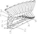
- a cutting device as shown in Figs. 1 and 2includes a drive shaft 1, a first blade 2, and the drive shaft 1 and the first blade 2 are respectively mounted on a cutter. Mounted on the drive shaft 1 There are more than 8 blade support frames 3 on which the second blade 4 is mounted, and the first blade 2 is provided with a cutting groove 5, the second blade 4 and the cutting groove 5 Cut surfaces 6 are respectively opened.
- the second blade 4adopts a second blade of an arc shape, and the first blade 2 is provided with an arc-shaped cutting groove for use in cooperation with a second blade of an arc shape.
- the blade support frame 3includes a support shaft 7 on which a blade mount 8 is mounted, on which the second blade 4 is mounted, and on the adjacent two support frames 3
- the angle between the blade mounts 8is ⁇ , and the value of ⁇ is 12°.
- Three blade mounts 8are mounted equidistantly on the support shaft 7.
- the angle between the extension of the radius of the drive shaft 1 and the second blade 4is ⁇ , and the value of ⁇ is 10°.
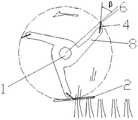
- the cutting deviceis in the arc-shaped cutting groove 5 when the grass or the plant is cut, the drive shaft 1 drives the blade support frame 3 to perform a circular motion, and the arc-shaped second blade mounted on the blade mounting frame 8 4 sliding from the arc-shaped cutting groove 5, cutting the grass or the plant by the clamping force between the cutting groove 5 and the second blade 4.
- the cutting device of the embodimenthas a simple structure, the driving force is greatly reduced in the same cutting area, the energy consumption is reduced, the operation is convenient and labor-saving, the cutting efficiency is high, the cutting section is neat, the cutting plant is not easy to be injured, and the cutting and cutting are convenient. After the cut.
- a cutting device as shown in Fig. 3includes a drive shaft 1, a first blade 2, and the drive shaft 1, the first blade 2 are respectively mounted on a cutter.
- the drive shaft 1is mounted with more than 8 blade support frames 3, and the blade support frame 3 is mounted with a second blade 4, and the first blade 2 is provided with a cutting groove 5, the second blade 4 is provided with a cut surface 6.
- the second blade 4adopts a triangular second blade, and the first blade 2 is provided with a triangular cutting groove for use with an arc-shaped second blade.
- the blade support frame 3includes a support shaft 7 on which a blade mount 8 is mounted, on which the second blade 4 is mounted, and on the adjacent two support frames 3
- the angle between the blade mounts 8is ⁇ , and the value of ⁇ is 30°.
- Three blade mounts 8are mounted equidistantly on the support shaft 7.
- the angle between the extension of the radius of the drive shaft 1 and the second blade 4is ⁇ , and the value of ⁇ is 35°.
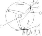
- the cutting device of the embodimentis a triangular cutting groove of grass or plant when cutting 5, the drive shaft 1 drives the blade support frame 3 to perform a circular motion, and the triangular second blade 4 mounted on the blade mount 8 slides from the triangular-shaped cutting groove 5 through the cutting groove 5 and the second blade The force between 4 cuts off grass or plants.
- the cutting device of the embodimenthas a simple structure, the driving force is greatly reduced in the same cutting area, the energy consumption is reduced, the operation is convenient and labor-saving, the cutting efficiency is high, the cutting section is neat, the cutting plant is not easy to be injured, and the cutting and cutting are convenient. After the cut.
- a cutting device as shown in Fig. 4includes a drive shaft 1, a first blade 2, and the drive shaft 1, the first blade 2 are respectively mounted on a cutter.
- the drive shaft 1is mounted with more than 8 blade support frames 3, and the blade support frame 3 is mounted with a second blade 4, and the first blade 2 is provided with a cutting groove 5, the cutting groove 5 is provided with a cut surface 6.
- the second blade 4is a second blade having a rectangular shape, and the first blade 2 is provided with a rectangular cutting groove for use with a rectangular second blade.
- the blade support frame 3includes a support shaft 7 on which a blade mount 8 is mounted, on which the second blade 4 is mounted, and on the adjacent two support frames 3
- the angle between the blade mounts 8is ⁇ , and the value of ⁇ is 60°.
- Three blade mounts 8are mounted equidistantly on the support shaft 7.
- the angle between the extension of the radius of the drive shaft 1 and the second blade 4is ⁇ , and the value of ⁇ is 45°.
- the cutting deviceis in the rectangular cutting groove 5 when the grass or the plant is cut, the drive shaft 1 drives the blade support frame 3 to perform circular motion, and the rectangular second blade is mounted on the blade mounting frame 8. 4 is slid from the rectangular cutting groove 5, and the grass or the plant is cut by the clamping force between the cutting groove 5 and the second blade 4.
- the cutting device of the embodimenthas a simple structure, the driving force is greatly reduced in the same cutting area, the energy consumption is reduced, the operation is convenient and labor-saving, the cutting efficiency is high, the cutting section is neat, the cutting plant is not easy to be injured, and the cutting and cutting are convenient. After the cut.
Landscapes
- Life Sciences & Earth Sciences (AREA)
- Environmental Sciences (AREA)
- Harvester Elements (AREA)
Abstract
Description
本发明涉及一种切割装置。The invention relates to a cutting device.
割草机是一种用于修剪草坪、植被等的机械工具,它是由刀盘、发动机、行走轮、行走机构、刀片、扶手、控制部分组成。目前市场上割草机中的切割装置可分为以下几类:1、在驱动轴上安装切割条或绳,如专利号:CN201210002402.6,专利名称:一种割草机组合刀具,以驱动轴的快速转动带动切割条或绳进行割草。采用此种割草方式需驱动力大,能耗高,切割面不齐且易损伤植物。2、在驱动轴上安装切割刀,如专利号:CN201210496286.8,专利名称:割草机的切割装置以及切割装置的安装方法,以驱动轴的快速转动带动切割刀进行割草。采用此种割草方式同样存在需驱动力大,能耗高,切割面不齐且易损伤植物。3、剪刀式切割,如专利号:CN201310256866.4,专利名称:一种双层刀片割草机;通过两片叠合式的切割刀片切割。采用此种切割方式存在切割后的切割物不易收集,两片刀片存在间隙,易于损坏。4、滚筒式切割,如专利号:CN201110431994.9,专利名称:一种滚刀式割草机构,通过滚筒切刀切割。采用此种切割方式存在制造成本高,制造精度要求高,切割长度受滚筒切刀高度的限制,无法切割过长的植物。The lawn mower is a mechanical tool for mowing lawns, vegetation, etc., and is composed of a cutter head, an engine, a traveling wheel, a traveling mechanism, a blade, an armrest, and a control portion. At present, the cutting devices in the lawn mower can be divided into the following categories: 1. A cutting bar or a rope is installed on the driving shaft, such as patent number: CN201210002402.6, patent name: a mower combined tool to drive The rapid rotation of the shaft drives the cutting strip or rope for mowing. The use of such a mowing method requires a large driving force, high energy consumption, uneven cutting surface and easy damage to plants. 2. Install a cutting knife on the drive shaft, such as patent number: CN201210496286.8, patent name: cutting device of the lawn mower and installation method of the cutting device, and drive the cutting knife to cut grass with the rapid rotation of the driving shaft. The use of such a mowing method also has a large driving force, high energy consumption, uneven cutting surface and easy damage to plants. 3. Scissor cutting, such as patent number: CN201310256866.4, patent name:a double-layer blade mower; cut by two-piece cutting blade. With this cutting method, the cut pieces after cutting are difficult to collect, and the two blades have gaps and are easily damaged. 4. Roller type cutting, such as patent number: CN201110431994.9, patent name: a hob type mowing mechanism, which is cut by a drum cutter. The use of such a cutting method has high manufacturing cost, high manufacturing precision, and the cutting length is limited by the height of the drum cutter, and the plant cannot be cut too long.
发明的公开Disclosure of invention
本发明的目的在于提供一种切割装置,其结构简单,在相同的切割面积其驱动力大大降低,降低能耗的同时操作方便省力,切割效率高,切割断面整齐,切割植物不易受伤,且便于收集切割后的切割物。The object of the present invention is to provide a cutting device which has a simple structure, greatly reduces the driving force in the same cutting area, reduces the energy consumption, and has convenient and labor-saving operation, high cutting efficiency, neat cutting section, easy to cut plants, and easy to cut. The cut cuts are collected.
为了达到上述目的,本发明的技术方案是:In order to achieve the above object, the technical solution of the present invention is:
一种切割装置,包括第一刀片和相对第一刀片做圆周运动的刀片支撑机构,所述刀片支撑机构上安装有第二刀片;所述第一刀片上开设有切割凹槽,所述第二刀片和/或切割凹槽上开设有切面。A cutting device comprising a first blade and a blade supporting mechanism for circular movement relative to the first blade, the blade supporting mechanism is mounted with a second blade; the first blade is provided with a cutting groove, the second A cut surface is formed on the blade and/or the cutting groove.
所述刀片支撑机构包括驱动轴,所述驱动轴上安装有1个以上的刀片支撑架,所述刀片支撑架上安装有第二刀片。The blade support mechanism includes a drive shaft on which one or more blade support frames are mounted, and a second blade is mounted on the blade support frame.
所述刀片支撑架包括支撑轴,所述支撑轴上安装有刀片安装架,所述刀片安装架上安装有第二刀片,且相邻2个所述支撑架上的刀片安装架之间的夹角为0—60°。The blade support frame includes a support shaft on which a blade mount is mounted, a second blade is mounted on the blade mount, and a clip between the blade mounts on two adjacent support racks The angle is 0-60°.
所述支撑轴上等距安装有3个刀片安装架。Three blade mounts are mounted equidistantly on the support shaft.
所述驱动轴的半径延长线与第二刀片之间的夹角为10—45°。The angle between the extension of the radius of the drive shaft and the second blade is 10 - 45 degrees.
所述第二刀片采用弧形状的第二刀片,所述第一刀片上开设有弧形状的切割凹槽。The second blade adopts a second blade in the shape of an arc, and the first blade is provided with an arc-shaped cutting groove.
所述第二刀片采用三角状的第二刀片,所述第一刀片上开设有三角状的切割凹槽。The second blade adopts a triangular second blade, and the first blade is provided with a triangular cutting groove.
所述第二刀片采用矩形状的第二刀片,所述第一刀片上开设有矩形状的切割凹槽。The second blade adopts a second blade having a rectangular shape, and the first blade is provided with a rectangular cutting groove.
本发明的有益效果是:一种切割装置,其结构简单,在相同的切割面积其驱动力大大降低,降低能耗的同时操作方便省力,切割效率高,切割断面整齐,切割植物不易受伤,且便于收集切割后的切割物。The utility model has the beneficial effects that the cutting device has a simple structure, the driving force is greatly reduced in the same cutting area, the energy consumption is reduced, the operation is convenient and labor-saving, the cutting efficiency is high, the cutting section is neat, the cutting plant is not easily injured, and It is convenient to collect the cut pieces after cutting.
附图的简要说明BRIEF DESCRIPTION OF THE DRAWINGS
图1为实施例一的结构示意图;1 is a schematic structural view ofEmbodiment 1;
图2为图1中切割装置的切割示意图;Figure 2 is a schematic view showing the cutting of the cutting device of Figure 1;
图3为实施例二的结构示意图;3 is a schematic structural view ofEmbodiment 2;
图4为图3中切割装置的切割示意图;Figure 4 is a schematic view showing the cutting of the cutting device of Figure 3;
图5为实施例三的结构示意图;Figure 5 is a schematic structural view ofEmbodiment 3;
图6为图5中切割装置的切割示意图。Figure 6 is a schematic view showing the cutting of the cutting device of Figure 5.
实现本发明的最佳方式The best way to implement the invention
实施例1Example 1
如图1、图2所示一种切割装置,包括驱动轴1、第一刀片2,所述驱动轴1、第一刀片2分别安装在切割机上。所述驱动轴1上安装有8个以上的刀片支撑架3,所述刀片支撑架3上安装有第二刀片4,所述第一刀片2上开设有切割凹槽5,所述第二刀片4和切割凹槽5上分别开设有切面6。所述第二刀片4采用弧形状的第二刀片,所述第一刀片2上开设有与弧形状的第二刀片配合使用的弧形状的切割凹槽。A cutting device as shown in Figs. 1 and 2 includes adrive shaft 1, afirst blade 2, and thedrive shaft 1 and thefirst blade 2 are respectively mounted on a cutter. Mounted on thedrive shaft 1There are more than 8blade support frames 3 on which thesecond blade 4 is mounted, and thefirst blade 2 is provided with a cutting groove 5, thesecond blade 4 and the cutting groove 5Cut surfaces 6 are respectively opened. Thesecond blade 4 adopts a second blade of an arc shape, and thefirst blade 2 is provided with an arc-shaped cutting groove for use in cooperation with a second blade of an arc shape.
所述刀片支撑架3包括支撑轴7,所述支撑轴7上安装有刀片安装架8,所述刀片安装架8上安装有第二刀片4,且所述相邻2个支撑架3上的刀片安装架8之间的夹角为ɑ,ɑ的值为12°。所述支撑轴7上等距安装有3个刀片安装架8。所述驱动轴1的半径延长线与第二刀片4之间的夹角为β,β的值为10°。Theblade support frame 3 includes asupport shaft 7 on which ablade mount 8 is mounted, on which thesecond blade 4 is mounted, and on the adjacent twosupport frames 3 The angle between theblade mounts 8 is ɑ, and the value of ɑ is 12°. Threeblade mounts 8 are mounted equidistantly on thesupport shaft 7. The angle between the extension of the radius of thedrive shaft 1 and thesecond blade 4 is β, and the value of β is 10°.
本实施例所述的切割装置在切割时草或植物在弧形状的切割凹槽5内,驱动轴1驱动刀片支撑架3做圆周运动,安装在刀片安装架8上的弧形状的第二刀片4从弧形状的切割凹槽5内滑动,通过切割凹槽5与第二刀片4之间的夹力切断草或植物。The cutting device according to the embodiment is in the arc-shaped cutting groove 5 when the grass or the plant is cut, thedrive shaft 1 drives theblade support frame 3 to perform a circular motion, and the arc-shaped second blade mounted on theblade mounting frame 8 4 sliding from the arc-shaped cutting groove 5, cutting the grass or the plant by the clamping force between the cutting groove 5 and thesecond blade 4.
本实施例的一种切割装置,其结构简单,在相同的切割面积其驱动力大大降低,降低能耗的同时操作方便省力,切割效率高,切割断面整齐,切割植物不易受伤,且便于收集切割后的切割物。The cutting device of the embodiment has a simple structure, the driving force is greatly reduced in the same cutting area, the energy consumption is reduced, the operation is convenient and labor-saving, the cutting efficiency is high, the cutting section is neat, the cutting plant is not easy to be injured, and the cutting and cutting are convenient. After the cut.
实施例2Example 2
如图3所示一种切割装置,包括驱动轴1、第一刀片2,所述驱动轴1、第一刀片2分别安装在切割机上。所述驱动轴1上安装有8个以上的刀片支撑架3,所述刀片支撑架3上安装有第二刀片4,所述第一刀片2上开设有切割凹槽5,所述第二刀片4上开设有切面6。所述第二刀片4采用三角状的第二刀片,所述第一刀片2上开设有与弧形状的第二刀片配合使用的三角状的切割凹槽。A cutting device as shown in Fig. 3 includes adrive shaft 1, afirst blade 2, and thedrive shaft 1, thefirst blade 2 are respectively mounted on a cutter. Thedrive shaft 1 is mounted with more than 8blade support frames 3, and theblade support frame 3 is mounted with asecond blade 4, and thefirst blade 2 is provided with a cutting groove 5, thesecond blade 4 is provided with acut surface 6. Thesecond blade 4 adopts a triangular second blade, and thefirst blade 2 is provided with a triangular cutting groove for use with an arc-shaped second blade.
所述刀片支撑架3包括支撑轴7,所述支撑轴7上安装有刀片安装架8,所述刀片安装架8上安装有第二刀片4,且所述相邻2个支撑架3上的刀片安装架8之间的夹角为ɑ,ɑ的值为30°。所述支撑轴7上等距安装有3个刀片安装架8。所述驱动轴1的半径延长线与第二刀片4之间的夹角为β,β的值为35°。Theblade support frame 3 includes asupport shaft 7 on which ablade mount 8 is mounted, on which thesecond blade 4 is mounted, and on the adjacent twosupport frames 3 The angle between theblade mounts 8 is ɑ, and the value of ɑ is 30°. Threeblade mounts 8 are mounted equidistantly on thesupport shaft 7. The angle between the extension of the radius of thedrive shaft 1 and thesecond blade 4 is β, and the value of β is 35°.
本实施例所述的切割装置在切割时草或植物在三角状的切割凹槽5内,驱动轴1驱动刀片支撑架3做圆周运动,安装在刀片安装架8上的三角状的第二刀片4从三角状的切割凹槽5内滑动,通过切割凹槽5与第二刀片4之间的夹力切断草或植物。The cutting device of the embodiment is a triangular cutting groove of grass or plant when cutting5, thedrive shaft 1 drives theblade support frame 3 to perform a circular motion, and the triangularsecond blade 4 mounted on theblade mount 8 slides from the triangular-shaped cutting groove 5 through the cutting groove 5 and the second blade The force between 4 cuts off grass or plants.
本实施例的一种切割装置,其结构简单,在相同的切割面积其驱动力大大降低,降低能耗的同时操作方便省力,切割效率高,切割断面整齐,切割植物不易受伤,且便于收集切割后的切割物。The cutting device of the embodiment has a simple structure, the driving force is greatly reduced in the same cutting area, the energy consumption is reduced, the operation is convenient and labor-saving, the cutting efficiency is high, the cutting section is neat, the cutting plant is not easy to be injured, and the cutting and cutting are convenient. After the cut.
实施例3Example 3
如图4所示一种切割装置,包括驱动轴1、第一刀片2,所述驱动轴1、第一刀片2分别安装在切割机上。所述驱动轴1上安装有8个以上的刀片支撑架3,所述刀片支撑架3上安装有第二刀片4,所述第一刀片2上开设有切割凹槽5,所述切割凹槽5上开设有切面6。所述第二刀片4采用矩形状的第二刀片,所述第一刀片2上开设有与矩形状的第二刀片配合使用的矩形状的切割凹槽。A cutting device as shown in Fig. 4 includes adrive shaft 1, afirst blade 2, and thedrive shaft 1, thefirst blade 2 are respectively mounted on a cutter. Thedrive shaft 1 is mounted with more than 8blade support frames 3, and theblade support frame 3 is mounted with asecond blade 4, and thefirst blade 2 is provided with a cutting groove 5, the cutting groove 5 is provided with acut surface 6. Thesecond blade 4 is a second blade having a rectangular shape, and thefirst blade 2 is provided with a rectangular cutting groove for use with a rectangular second blade.
所述刀片支撑架3包括支撑轴7,所述支撑轴7上安装有刀片安装架8,所述刀片安装架8上安装有第二刀片4,且所述相邻2个支撑架3上的刀片安装架8之间的夹角为ɑ,ɑ的值为60°。所述支撑轴7上等距安装有3个刀片安装架8。所述驱动轴1的半径延长线与第二刀片4之间的夹角为β,β的值为45°。Theblade support frame 3 includes asupport shaft 7 on which ablade mount 8 is mounted, on which thesecond blade 4 is mounted, and on the adjacent twosupport frames 3 The angle between theblade mounts 8 is ɑ, and the value of ɑ is 60°. Threeblade mounts 8 are mounted equidistantly on thesupport shaft 7. The angle between the extension of the radius of thedrive shaft 1 and thesecond blade 4 is β, and the value of β is 45°.
本实施例所述的切割装置在切割时草或植物在矩形状的切割凹槽5内,驱动轴1驱动刀片支撑架3做圆周运动,安装在刀片安装架8上的矩形状的第二刀片4从矩形状的切割凹槽5内滑动,通过切割凹槽5与第二刀片4之间的夹力切断草或植物。The cutting device according to the embodiment is in the rectangular cutting groove 5 when the grass or the plant is cut, thedrive shaft 1 drives theblade support frame 3 to perform circular motion, and the rectangular second blade is mounted on theblade mounting frame 8. 4 is slid from the rectangular cutting groove 5, and the grass or the plant is cut by the clamping force between the cutting groove 5 and thesecond blade 4.
本实施例的一种切割装置,其结构简单,在相同的切割面积其驱动力大大降低,降低能耗的同时操作方便省力,切割效率高,切割断面整齐,切割植物不易受伤,且便于收集切割后的切割物。The cutting device of the embodiment has a simple structure, the driving force is greatly reduced in the same cutting area, the energy consumption is reduced, the operation is convenient and labor-saving, the cutting efficiency is high, the cutting section is neat, the cutting plant is not easy to be injured, and the cutting and cutting are convenient. After the cut.
Claims (8)
- 一种切割装置,其特征在于:包括第一刀片(2)和相对第一刀片(2)做圆周运动的刀片支撑机构,所述刀片支撑机构上安装有第二刀片(4);所述第一刀片(2)上开设有切割凹槽(5),所述第二刀片(4)和/或切割凹槽(5)上开设有切面(6)。A cutting device, comprising: a first blade (2) and a blade supporting mechanism for circular movement relative to the first blade (2), wherein the blade supporting mechanism is mounted with a second blade (4); A blade (2) is provided with a cutting groove (5), and the second blade (4) and/or the cutting groove (5) is provided with a cutting surface (6).
- 根据权利要求1所述的一种切割装置,其特征在于:所述刀片支撑机构包括驱动轴(1),所述驱动轴(1)上安装有1个以上的刀片支撑架(3),所述刀片支撑架(3)上安装有第二刀片(4)。A cutting device according to claim 1, wherein said blade supporting mechanism comprises a drive shaft (1), and said drive shaft (1) is mounted with more than one blade support frame (3). A second blade (4) is mounted on the blade support frame (3).
- 根据权利要求2所述的一种切割装置,其特征在于:所述刀片支撑架(3)包括支撑轴(7),所述支撑轴(7)上安装有刀片安装架(8),所述刀片安装架(8)上安装有第二刀片(4),且相邻2个所述支撑架(3)上的刀片安装架(8)之间的夹角为0—60°。A cutting device according to claim 2, wherein said blade support frame (3) comprises a support shaft (7), and said support shaft (7) is mounted with a blade mount (8), said A second blade (4) is mounted on the blade mount (8), and an angle between the blade mounts (8) on two adjacent support frames (3) is 0-60.
- 根据权利要求3所述的一种切割装置,其特征在于:所述支撑轴(7)上等距安装有3个刀片安装架(8)。A cutting device according to claim 3, characterized in that the support shaft (7) is equidistantly mounted with three blade mounts (8).
- 根据权利要求2所述的一种切割装置,其特征在于:所述驱动轴(1)的半径延长线与第二刀片(4)之间的夹角为10—45°。A cutting device according to claim 2, characterized in that the angle between the radius extension of the drive shaft (1) and the second blade (4) is between 10 and 45 degrees.
- 根据权利要求1所述的一种切割装置,其特征在于:所述第二刀片(4)采用弧形状的第二刀片,所述第一刀片(2)上开设有弧形状的切割凹槽。A cutting device according to claim 1, characterized in that the second blade (4) adopts a second blade of an arc shape, and the first blade (2) is provided with an arc-shaped cutting groove.
- 根据权利要求1所述的一种切割装置,其特征在于:所述第二刀片(4)采用三角状的第二刀片,所述第一刀片(2)上开设有三角状的切割凹槽。A cutting device according to claim 1, characterized in that the second blade (4) adopts a triangular second blade, and the first blade (2) is provided with a triangular cutting groove.
- 根据权利要求1所述的一种切割装置,其特征在于:所述第二刀片(4)采用矩形状的第二刀片,所述第一刀片(2)上开设有矩形状的切割凹槽。A cutting device according to claim 1, characterized in that the second blade (4) adopts a rectangular second blade, and the first blade (2) is provided with a rectangular cutting groove.
Priority Applications (4)
| Application Number | Priority Date | Filing Date | Title |
|---|---|---|---|
| AU2014411113AAU2014411113B2 (en) | 2014-11-14 | 2014-11-20 | Cutting device |
| US14/786,538US20160345494A1 (en) | 2014-11-14 | 2014-11-20 | A cutting device |
| EP14889784.6AEP3033934A4 (en) | 2014-11-14 | 2014-11-20 | CUTTING DEVICE |
| JP2016576002AJP6553659B2 (en) | 2014-11-14 | 2014-11-20 | Cutting device |
Applications Claiming Priority (2)
| Application Number | Priority Date | Filing Date | Title |
|---|---|---|---|
| CN201410641849.7 | 2014-11-14 | ||
| CN201410641849.7ACN104365268B (en) | 2014-11-14 | 2014-11-14 | A kind of cutter sweep |
Publications (1)
| Publication Number | Publication Date |
|---|---|
| WO2016074270A1true WO2016074270A1 (en) | 2016-05-19 |
Family
ID=52544671
Family Applications (1)
| Application Number | Title | Priority Date | Filing Date |
|---|---|---|---|
| PCT/CN2014/091756WO2016074270A1 (en) | 2014-11-14 | 2014-11-20 | Cutting device |
Country Status (6)
| Country | Link |
|---|---|
| US (1) | US20160345494A1 (en) |
| EP (1) | EP3033934A4 (en) |
| JP (1) | JP6553659B2 (en) |
| CN (1) | CN104365268B (en) |
| AU (1) | AU2014411113B2 (en) |
| WO (1) | WO2016074270A1 (en) |
Families Citing this family (1)
| Publication number | Priority date | Publication date | Assignee | Title |
|---|---|---|---|---|
| CN107094516A (en)* | 2016-02-23 | 2017-08-29 | 朱培池 | A kind of greenbelt pruning shear |
Citations (4)
| Publication number | Priority date | Publication date | Assignee | Title |
|---|---|---|---|---|
| WO2011152719A1 (en)* | 2010-05-31 | 2011-12-08 | Maredo B.V. | Device for removing weeds from lawns |
| WO2013009238A1 (en)* | 2011-07-08 | 2013-01-17 | Mats Fischier i Båstad AB | Device for mowing |
| CN202799651U (en)* | 2012-10-08 | 2013-03-20 | 金华市赛格五金注塑有限公司 | Hob assembly of lawn mower |
| CN103314702A (en)* | 2013-07-03 | 2013-09-25 | 南通普乐工具有限公司 | Rotary drum type mower |
Family Cites Families (29)
| Publication number | Priority date | Publication date | Assignee | Title |
|---|---|---|---|---|
| US1370352A (en)* | 1920-06-15 | 1921-03-01 | Lemuel D Parmley | Cutter for harvesters |
| US2762187A (en)* | 1954-01-26 | 1956-09-11 | John C Fortis | Lawnmower clipper attachment |
| US2772533A (en)* | 1955-01-17 | 1956-12-04 | Jr Harry B Shibley | Mower having ledger plate with cooperating wobble plate cutter |
| US2790293A (en)* | 1956-03-30 | 1957-04-30 | John V Crotty | Rotary cutting mechanism including cooperating toothed stationary cutter bar |
| GB981895A (en)* | 1962-02-21 | 1965-01-27 | Edward Thomas & Co Oswestry Lt | Improvements in or relating to motor lawn mowers |
| JPS4863389U (en)* | 1971-11-15 | 1973-08-11 | ||
| JPS4987864U (en)* | 1972-11-20 | 1974-07-30 | ||
| JPS5964624U (en)* | 1982-10-25 | 1984-04-28 | カワサキ機工株式会社 | Rotor type rotary blade of tea leaf plucking machine |
| EP0238827A1 (en)* | 1986-02-17 | 1987-09-30 | Klöckner-Humboldt-Deutz Aktiengesellschaft | Moving implement |
| DE3701668A1 (en)* | 1986-10-22 | 1988-08-04 | Wieneke Franz | MOWING SNAIL |
| GB2203623A (en)* | 1987-04-16 | 1988-10-26 | Raymond Hugh Kerr | Forage harvester |
| US5107591A (en)* | 1991-04-01 | 1992-04-28 | Hikari Corporation | Thinning scissors |
| US5402629A (en)* | 1991-08-30 | 1995-04-04 | Masaru; Tsuda | Mowing machine and structure for discharged mowed grass |
| JPH0746102Y2 (en)* | 1992-04-14 | 1995-10-25 | 株式会社共栄社 | Lawn mower |
| US5553380A (en)* | 1994-07-18 | 1996-09-10 | Rice; James | Mower head roller assembly |
| JPH0837870A (en)* | 1994-08-01 | 1996-02-13 | Masaru Tsuda | Reel type lawn mower or weeder |
| JPH0853250A (en)* | 1994-08-11 | 1996-02-27 | Toshiba Mach Co Ltd | Paper cutter |
| US5678396A (en)* | 1995-08-23 | 1997-10-21 | Deere & Company | Sectioned grooved roller scraper |
| CN2272186Y (en)* | 1996-11-26 | 1998-01-14 | 刘念先 | Harvester for crops by cutting |
| FR2784852B1 (en)* | 1998-10-26 | 2001-02-16 | Emmanuelle Masson | PLANT CUTTING DEVICE |
| US20050102843A1 (en)* | 2003-11-17 | 2005-05-19 | Yuning Jiang | Cutting device with spiral blades |
| ITRM20060268A1 (en)* | 2006-05-18 | 2007-11-19 | Bimek S R L | TRINCIATORE DEVICE IN PARTICULAR FOR AGRICULTURAL MACHINES |
| US7644568B2 (en)* | 2008-05-16 | 2010-01-12 | Textron Inc. | Serrated edge bed knife |
| CN202722033U (en)* | 2012-07-06 | 2013-02-13 | 浙江省华贸实业有限公司 | Cutter disk structure of mower |
| GB201219124D0 (en)* | 2012-10-24 | 2012-12-05 | Richard Campey Ltd | Turf treatment implement |
| US9119344B2 (en)* | 2013-02-05 | 2015-09-01 | The Toro Company | Reel mower having quick change grooming attachments |
| US9402350B2 (en)* | 2013-05-23 | 2016-08-02 | Limb Beaver, LLC | Cutter apparatus |
| CN204259404U (en)* | 2014-11-14 | 2015-04-15 | 上虞市冠业电器有限公司 | A kind of cutting mechanism |
| CN204259406U (en)* | 2014-11-14 | 2015-04-15 | 上虞市冠业电器有限公司 | A kind of cutter sweep |
- 2014
- 2014-11-14CNCN201410641849.7Apatent/CN104365268B/enactiveActive
- 2014-11-20WOPCT/CN2014/091756patent/WO2016074270A1/enactiveApplication Filing
- 2014-11-20AUAU2014411113Apatent/AU2014411113B2/ennot_activeCeased
- 2014-11-20JPJP2016576002Apatent/JP6553659B2/enactiveActive
- 2014-11-20USUS14/786,538patent/US20160345494A1/ennot_activeAbandoned
- 2014-11-20EPEP14889784.6Apatent/EP3033934A4/ennot_activeCeased
Patent Citations (4)
| Publication number | Priority date | Publication date | Assignee | Title |
|---|---|---|---|---|
| WO2011152719A1 (en)* | 2010-05-31 | 2011-12-08 | Maredo B.V. | Device for removing weeds from lawns |
| WO2013009238A1 (en)* | 2011-07-08 | 2013-01-17 | Mats Fischier i Båstad AB | Device for mowing |
| CN202799651U (en)* | 2012-10-08 | 2013-03-20 | 金华市赛格五金注塑有限公司 | Hob assembly of lawn mower |
| CN103314702A (en)* | 2013-07-03 | 2013-09-25 | 南通普乐工具有限公司 | Rotary drum type mower |
Non-Patent Citations (1)
| Title |
|---|
| See also references ofEP3033934A4 |
Also Published As
| Publication number | Publication date |
|---|---|
| AU2014411113A1 (en) | 2017-01-12 |
| JP6553659B2 (en) | 2019-07-31 |
| JP2017522020A (en) | 2017-08-10 |
| AU2014411113B2 (en) | 2017-10-05 |
| US20160345494A1 (en) | 2016-12-01 |
| EP3033934A4 (en) | 2016-11-23 |
| CN104365268A (en) | 2015-02-25 |
| EP3033934A1 (en) | 2016-06-22 |
| CN104365268B (en) | 2016-09-28 |
Similar Documents
| Publication | Publication Date | Title |
|---|---|---|
| CN103355054B (en) | Anti-winding shaft and fastening device for harvester cutting disc | |
| WO2016074270A1 (en) | Cutting device | |
| CN104412770A (en) | Lawn repairer | |
| CN204259404U (en) | A kind of cutting mechanism | |
| CN204259406U (en) | A kind of cutter sweep | |
| CN202697249U (en) | Lawn mower | |
| CN202225249U (en) | Plastic film rim charge cutting device | |
| CN205232891U (en) | Shaping blade of pruning of electronic hedgeclipper of hand -held type | |
| CN203423970U (en) | Lawn mower flail knife | |
| CN203537851U (en) | Novel mower | |
| CN203541386U (en) | Reinforcing steel bar cutting device with cutter position adjustable | |
| CN205566991U (en) | A gear sword structure for citrus orchard loosens soil | |
| CN104186101A (en) | Lawn mower for bidirectional rotary shearing and automatic blade protection | |
| CN203818650U (en) | Line pressing mechanism of line pressing and longitudinally-cutting machine for paperboard | |
| CN218851342U (en) | Gardens maintenance of equipment | |
| CN205614747U (en) | A cutting machine for discontinuous material | |
| CN204616504U (en) | Plane topiaries machine | |
| CN210641442U (en) | Cutting equipment for greening | |
| CN217694483U (en) | Double-layer crawler-type tobacco topping device | |
| CN204994257U (en) | Lawn mower is used in gardens | |
| CN204888035U (en) | Material cutting separator is planted in gardens | |
| CN203279554U (en) | Saw-web-type branch chopping machine | |
| CN221576115U (en) | Weeding equipment for weeding crops | |
| CN214545687U (en) | An easy-to-operate green lawn mower | |
| CN202998786U (en) | Rotary cultivation device of rotary cultivator |
Legal Events
| Date | Code | Title | Description |
|---|---|---|---|
| WWE | Wipo information: entry into national phase | Ref document number:14786538 Country of ref document:US | |
| REEP | Request for entry into the european phase | Ref document number:2014889784 Country of ref document:EP | |
| WWE | Wipo information: entry into national phase | Ref document number:2014889784 Country of ref document:EP | |
| ENP | Entry into the national phase | Ref document number:2016576002 Country of ref document:JP Kind code of ref document:A | |
| ENP | Entry into the national phase | Ref document number:2014411113 Country of ref document:AU Date of ref document:20141120 Kind code of ref document:A | |
| NENP | Non-entry into the national phase | Ref country code:DE |