WO2016042926A1 - Image processing device, image processing method, and program - Google Patents
Image processing device, image processing method, and programDownload PDFInfo
- Publication number
- WO2016042926A1 WO2016042926A1PCT/JP2015/071750JP2015071750WWO2016042926A1WO 2016042926 A1WO2016042926 A1WO 2016042926A1JP 2015071750 WJP2015071750 WJP 2015071750WWO 2016042926 A1WO2016042926 A1WO 2016042926A1
- Authority
- WO
- WIPO (PCT)
- Prior art keywords
- image
- camera
- captured image
- image processing
- target object
- Prior art date
Links
Images


Classifications
- G—PHYSICS
- G08—SIGNALLING
- G08B—SIGNALLING OR CALLING SYSTEMS; ORDER TELEGRAPHS; ALARM SYSTEMS
- G08B13/00—Burglar, theft or intruder alarms
- G08B13/18—Actuation by interference with heat, light, or radiation of shorter wavelength; Actuation by intruding sources of heat, light, or radiation of shorter wavelength
- G08B13/189—Actuation by interference with heat, light, or radiation of shorter wavelength; Actuation by intruding sources of heat, light, or radiation of shorter wavelength using passive radiation detection systems
- G08B13/194—Actuation by interference with heat, light, or radiation of shorter wavelength; Actuation by intruding sources of heat, light, or radiation of shorter wavelength using passive radiation detection systems using image scanning and comparing systems
- G08B13/196—Actuation by interference with heat, light, or radiation of shorter wavelength; Actuation by intruding sources of heat, light, or radiation of shorter wavelength using passive radiation detection systems using image scanning and comparing systems using television cameras
- G08B13/19678—User interface
- G—PHYSICS
- G06—COMPUTING OR CALCULATING; COUNTING
- G06T—IMAGE DATA PROCESSING OR GENERATION, IN GENERAL
- G06T1/00—General purpose image data processing
- G—PHYSICS
- G06—COMPUTING OR CALCULATING; COUNTING
- G06T—IMAGE DATA PROCESSING OR GENERATION, IN GENERAL
- G06T19/00—Manipulating 3D models or images for computer graphics
- G—PHYSICS
- G06—COMPUTING OR CALCULATING; COUNTING
- G06T—IMAGE DATA PROCESSING OR GENERATION, IN GENERAL
- G06T19/00—Manipulating 3D models or images for computer graphics
- G06T19/006—Mixed reality
- G—PHYSICS
- G06—COMPUTING OR CALCULATING; COUNTING
- G06T—IMAGE DATA PROCESSING OR GENERATION, IN GENERAL
- G06T7/00—Image analysis
- G06T7/80—Analysis of captured images to determine intrinsic or extrinsic camera parameters, i.e. camera calibration
- G—PHYSICS
- G08—SIGNALLING
- G08B—SIGNALLING OR CALLING SYSTEMS; ORDER TELEGRAPHS; ALARM SYSTEMS
- G08B25/00—Alarm systems in which the location of the alarm condition is signalled to a central station, e.g. fire or police telegraphic systems
- G08B25/01—Alarm systems in which the location of the alarm condition is signalled to a central station, e.g. fire or police telegraphic systems characterised by the transmission medium
- G08B25/08—Alarm systems in which the location of the alarm condition is signalled to a central station, e.g. fire or police telegraphic systems characterised by the transmission medium using communication transmission lines
- H—ELECTRICITY
- H04—ELECTRIC COMMUNICATION TECHNIQUE
- H04N—PICTORIAL COMMUNICATION, e.g. TELEVISION
- H04N17/00—Diagnosis, testing or measuring for television systems or their details
- H04N17/002—Diagnosis, testing or measuring for television systems or their details for television cameras
- H—ELECTRICITY
- H04—ELECTRIC COMMUNICATION TECHNIQUE
- H04N—PICTORIAL COMMUNICATION, e.g. TELEVISION
- H04N23/00—Cameras or camera modules comprising electronic image sensors; Control thereof
- H04N23/60—Control of cameras or camera modules
- H04N23/63—Control of cameras or camera modules by using electronic viewfinders
- H—ELECTRICITY
- H04—ELECTRIC COMMUNICATION TECHNIQUE
- H04N—PICTORIAL COMMUNICATION, e.g. TELEVISION
- H04N5/00—Details of television systems
- H04N5/76—Television signal recording
- H—ELECTRICITY
- H04—ELECTRIC COMMUNICATION TECHNIQUE
- H04N—PICTORIAL COMMUNICATION, e.g. TELEVISION
- H04N5/00—Details of television systems
- H04N5/76—Television signal recording
- H04N5/765—Interface circuits between an apparatus for recording and another apparatus
- H04N5/77—Interface circuits between an apparatus for recording and another apparatus between a recording apparatus and a television camera
- H—ELECTRICITY
- H04—ELECTRIC COMMUNICATION TECHNIQUE
- H04N—PICTORIAL COMMUNICATION, e.g. TELEVISION
- H04N9/00—Details of colour television systems
- H04N9/79—Processing of colour television signals in connection with recording
- H04N9/87—Regeneration of colour television signals
- H04N9/8715—Regeneration of colour television signals involving the mixing of the reproduced video signal with a non-recorded signal, e.g. a text signal
- G—PHYSICS
- G06—COMPUTING OR CALCULATING; COUNTING
- G06T—IMAGE DATA PROCESSING OR GENERATION, IN GENERAL
- G06T2207/00—Indexing scheme for image analysis or image enhancement
- G06T2207/10—Image acquisition modality
- G06T2207/10016—Video; Image sequence
- G—PHYSICS
- G06—COMPUTING OR CALCULATING; COUNTING
- G06T—IMAGE DATA PROCESSING OR GENERATION, IN GENERAL
- G06T2207/00—Indexing scheme for image analysis or image enhancement
- G06T2207/20—Special algorithmic details
- G06T2207/20092—Interactive image processing based on input by user
- G06T2207/20096—Interactive definition of curve of interest
- G—PHYSICS
- G06—COMPUTING OR CALCULATING; COUNTING
- G06T—IMAGE DATA PROCESSING OR GENERATION, IN GENERAL
- G06T2207/00—Indexing scheme for image analysis or image enhancement
- G06T2207/20—Special algorithmic details
- G06T2207/20092—Interactive image processing based on input by user
- G06T2207/20101—Interactive definition of point of interest, landmark or seed
- G—PHYSICS
- G06—COMPUTING OR CALCULATING; COUNTING
- G06T—IMAGE DATA PROCESSING OR GENERATION, IN GENERAL
- G06T2207/00—Indexing scheme for image analysis or image enhancement
- G06T2207/30—Subject of image; Context of image processing
- G06T2207/30196—Human being; Person
- G—PHYSICS
- G06—COMPUTING OR CALCULATING; COUNTING
- G06T—IMAGE DATA PROCESSING OR GENERATION, IN GENERAL
- G06T2207/00—Indexing scheme for image analysis or image enhancement
- G06T2207/30—Subject of image; Context of image processing
- G06T2207/30232—Surveillance
- G—PHYSICS
- G06—COMPUTING OR CALCULATING; COUNTING
- G06V—IMAGE OR VIDEO RECOGNITION OR UNDERSTANDING
- G06V20/00—Scenes; Scene-specific elements
- G06V20/50—Context or environment of the image
- G06V20/52—Surveillance or monitoring of activities, e.g. for recognising suspicious objects
Definitions
- the present inventionrelates to image processing technology.
- the actual size or position of a person or thing shown in the video of the surveillance camerais information on the position and orientation of the camera (hereinafter referred to as camera parameters) and the image of the person or thing shown in the video (image). It can be calculated using the size and position above. With this calculation, for example, when an important person (such as a criminal of an incident) is shown in the video of the surveillance camera, the height of the person can be grasped using the video of the surveillance camera.
- Non-Patent Document 1captures a calibration pattern with a camera. From the correspondence between the three-dimensional coordinates of the calibration pattern in the real world and the two-dimensional coordinates of the calibration pattern on the captured image, the position and orientation of the camera are described. Discloses a method for estimating camera parameters (camera rotation and translation).
- estimated camera parametersare obtained and used. For example, obtain camera parameters that have been calculated by calibrating the target camera in the past, or obtain camera parameters defined based on information such as position and orientation when the camera was installed There are things to do.
- Camera parametersdo not always represent the position and orientation of the target camera.
- camera parameters representing positions and orientations different from the actual camera positions or orientationsmay be calculated due to input errors of corresponding points, lens distortion, and the like.
- the camera parametersdo not correctly represent the position and orientation of the target camera, for example, when calculating the height of an important person shown in the video of the monitoring camera described above, there is a problem that an error occurs in the calculation result.
- the object of the present inventionhas been made in view of the above problems.
- the objective of this inventionis providing the technique which can confirm easily whether a camera parameter is appropriate.
- a first image processing apparatusincludes a predetermined shape in real space superimposed on a captured image captured by a camera based on predetermined camera parameters representing the position and orientation of the camera, and Corresponding to the position on the captured image after the movement based on the input means for receiving the input of the movement operation on the captured image with respect to the first image representing the target object having a predetermined size.
- Presenting meansfor presenting a first image representing the target object in a visible manner.
- a second image processing apparatusincludes a display unit that displays a captured image captured by a camera, a parameter acquisition unit that acquires a camera parameter indicating the position and orientation of the camera, and a second unit on the captured image.
- the target object Presenting meansfor presenting, at the first position on the captured image, a first image representing the target object on the captured image captured by the camera parameter determined by the camera parameter when placed at the second position; .
- a third image processing apparatusincludes a first display unit that displays a captured image captured by a camera, a parameter acquisition unit that acquires a camera parameter that represents the position and orientation of the camera, and the captured image A plane parallel to the ground surface based on input means for receiving the input of a point or line, the camera parameter, the position of the point or line on the captured image, and the height information of the point or line in real space Second display means for displaying a first image representing the point or line when mapped on top.
- the first image processing method provided by the present inventionis executed by a computer.
- the image processing methodis an object in which a predetermined shape and a predetermined size in a real space are superimposed on a captured image captured by a camera based on predetermined camera parameters representing the position and orientation of the camera.
- the second image processing method provided by the present inventionis executed by a computer.
- the image processing methodincludes a display step for displaying a captured image captured by a camera, a parameter acquisition step for acquiring a camera parameter representing the position and orientation of the camera, and an input for receiving designation of a first position on the captured image.
- the target objectis placed at the second position based on the step, the camera parameter, the predetermined shape and size of the target object in the real space, and the second position in the real space corresponding to the first position.
- the third image processing method provided by the present inventionis executed by a computer.
- the image processing methodreceives a first display step for displaying a captured image captured by a camera, a parameter acquisition step for acquiring a camera parameter representing the position and orientation of the camera, and input of a point or a line with respect to the captured image. Based on the input step, the camera parameter, the position of the point or line on the captured image, and the height information of the point or line in real space, the mapping is performed on a plane parallel to the ground surface. And a second display step for displaying a first image representing a point or line.
- the program provided by the present inventioncauses a computer to operate as the first image processing apparatus, the second image processing apparatus, or the third image processing apparatus provided by the present invention.
- a technique for easily confirming whether or not a camera parameter is appropriateis provided.
- FIG. 1is a block diagram illustrating an image processing apparatus according to a first embodiment. It is a figure which illustrates a mode that the image processing apparatus presented the predetermined object on the captured image.
- 3is a flowchart illustrating a flow of processing executed by the image processing apparatus according to the first embodiment. It is a figure which illustrates the picked-up image by which the 1st image was shown by the presentation part. It is a block diagram which illustrates the hardware constitutions of an image processing apparatus. It is a figure which illustrates a mode that the 1st image showing the planar-shaped target object is shown on the captured image.
- FIG. 4is a block diagram illustrating an image processing apparatus according to a second embodiment.
- FIG. 6is a flowchart illustrating a flow of processing executed by the image processing apparatus according to the second embodiment. It is a figure which illustrates a mode that error information is shown on a captured image. It is a figure which illustrates a mode that a user moves a target object on a captured image.
- FIG. 6is a block diagram illustrating an image processing apparatus according to a third embodiment.
- 10is a flowchart illustrating the flow of processing executed by the image processing apparatus according to the third embodiment. It is a figure which illustrates the projection line of the target object shown on the picked-up image on the plane showing the ground surface demonstrated in Fig.9 (a).
- FIG. 1is a block diagram illustrating an image processing apparatus 2000 according to the first embodiment.
- arrowsindicate the flow of information.
- each blockrepresents a functional unit configuration, not a hardware unit configuration.
- the image processing apparatus 2000includes a display unit 2020, a parameter acquisition unit 2040, an input unit 2060, and a presentation unit 2080.
- Display unit 2020displays a captured image captured by the camera.
- the parameter acquisition unit 2040acquires camera parameters representing the camera position and orientation.
- the camera parametersmay include parameters other than the camera position and orientation. Camera parameters other than the camera position and orientation will be described later.
- the input unit 2060accepts designation of the first position on the captured image.
- the presentation unit 2080generates a first image representing the target object on the captured image that is captured by the camera determined by the camera parameter when the target object is placed at the second position in the real space corresponding to the first position.
- the first imageis an image representing how the target object looks from the viewpoint of the camera determined by the camera parameters.
- the second position in the real spacecan be obtained from the camera parameters, the height information of the first position, and the second position.
- “place the target object at the second position”means that the target object is assumed to exist at a position (second position) in the real space corresponding to the first position on the captured image.
- the presentation unit 2080generates a first image using the camera parameter, the predetermined shape and size of the target object in the real space, and the second position. Furthermore, the presentation unit 2080 presents the generated first image at the first position on the captured image.
- the target objectis a virtual object having a planar shape or a three-dimensional shape.
- the predetermined size and the predetermined shape set for the target objectare sizes and shapes that assume the real world. The predetermined size and the predetermined shape may be input by the user, or may be stored in advance or inside the image processing apparatus 2000.
- FIG. 2is a diagram illustrating a state in which the image processing apparatus 2000 presents a predetermined object on a captured image.
- the predetermined objectis a rectangular parallelepiped 20.
- FIG. 2Ashows a state in which the rectangular parallelepiped 20 is viewed from an appropriate angle.
- the cuboid 20has a horizontal and vertical length of 30 cm and a height of 170 cm.
- the rectangular parallelepiped 20 in this exampleis an object that simplifies the shape and size of an average person.
- FIG. 2Bis a diagram in which the image processing device 2000 presents the rectangular parallelepiped 20 on the captured image 10.
- the first position 30represents the first position input to the input unit 2060.
- the presentation unit 2080presents the first image 40 at the first position 30.
- the first image 40is an image that artificially represents the rectangular parallelepiped 20 captured by the camera.
- FIG. 3is a flowchart illustrating the flow of processing executed by the image processing apparatus 2000 according to the first embodiment.
- the display unit 2020displays a captured image captured by the camera.
- the input unit 2060accepts designation of the first position on the captured image.
- the parameter acquisition unit 2040acquires camera parameters representing the position and orientation of the camera.
- the presentation unit 2080generates a first image. As described above, the first image represents the target object on the captured image when it is captured by the camera determined by the camera parameter when placed at the second position.
- the presentation unit 2080presents the generated first image at the first position on the captured image.
- a process (step S106) of acquiring camera parametersmay be performed prior to a process of receiving an input of the first position (step S104).
- a camerathat captures a captured image displayed by the display unit 2020 when the user of the image processing apparatus 2000 views an object presented by the presentation unit 2080 (hereinafter, an actual camera). It is possible to easily confirm whether or not the position and posture of the camera are properly represented. Hereinafter, this will be described in detail with reference to FIG.
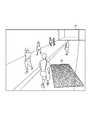
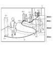
- FIG. 4is a diagram illustrating a captured image in which the first image is presented by the presentation unit 2080.
- FIG. 4Ais a diagram in a case where the camera parameters acquired by the parameter acquisition unit 2040 represent positions and orientations that approximate the actual camera positions and orientations.
- FIG. 4Bis a diagram when the camera parameter acquired by the parameter acquisition unit 2040 represents a position and orientation different from the actual camera position and orientation.
- the target object in FIG. 4is a rectangular parallelepiped having a height of 170 cm and both vertical and horizontal lengths of 30 cm as in the case of FIG.
- the first image presented by the presentation unit 2080is captured as if the target object placed at the location shown in the captured image was captured by the camera installed at the position and orientation represented by the camera parameters. Presented on the image. Therefore, when the camera parameter represents a position and orientation that approximates the position and orientation of the real camera, when the first image is compared with a person or an object shown on the captured image, the appearance by size and angle There is no sense of incongruity. For example, since the height of the target object is 170 cm, it is considered that when the target object is compared with a person, the height is approximately the same.
- FIG. 4since the side of the person shown in the captured image 10 is designated as the first position, the first image 40 is presented beside the person.
- FIG. 4Athe size of the person and the rectangular parallelepiped represented by the first image 40 is almost the same at any position, and there is no sense of incongruity.
- FIG. 4 (a)the rectangular parallelepiped represented by each first image 40 seems to be looked down from the front diagonally in the same manner as a person or a wall is seen from the front diagonally upward. There is no sense of incongruity about how each rectangular parallelepiped looks.
- FIG. 4Bthere is a sense of incongruity regarding how the rectangular parallelepiped represented by the first image 40 looks depending on the size and angle.
- the height of the rectangular parallelepiped represented by the first image 40-10is nearly twice as high as that of a person, and the first image 40-10 is the height placed at the place shown in the captured image 10-2. It cannot be said that it represents a 170 cm square object (cuboid 20).
- the upper surface of all the rectangular parallelepipedsis visible in the captured image 10-2, and the appearance is as if looking down from the vicinity. Yes.
- the depression angle in the camera viewing direction represented by the camera parameters in FIG. 4Bis larger than the depression angle in the viewing direction of the real camera. It can be expected that it has become.
- the usercan designate a plurality of first positions and place a plurality of target objects in one captured image.
- the user who uses the image processing apparatus 2000compares the first image presented by the presentation unit 2080 with the captured image, and is acquired by the parameter acquisition unit 2040. It is possible to easily grasp whether or not the obtained camera parameter represents a position and orientation that approximates the position and orientation of the camera that captured the captured image. If it can be confirmed that the position and orientation approximate to the position and orientation of the camera that captured the captured image can be confirmed, the user can determine that the combination of the camera parameter and the video of the monitoring camera may be used. Conversely, if it can be confirmed that it does not represent a position and orientation that approximates the position and orientation of the camera that captured the captured image, the camera parameters are estimated again, the position and orientation of the actual camera are corrected, etc. You can take action.
- Each functional component of the image processing apparatus 2000may be realized by a hardware component (eg, a hard-wired electronic circuit) that implements each functional component, or a hardware component and a software component. (For example, a combination of an electronic circuit and a program for controlling the electronic circuit).
- a hardware componenteg, a hard-wired electronic circuit
- a hardware component and a software componentfor example, a combination of an electronic circuit and a program for controlling the electronic circuit.
- FIG. 5is a block diagram illustrating a hardware configuration of the image processing apparatus 2000.
- the image processing apparatus 2000includes a bus 1020, a processor 1040, a memory 1060, a storage 1080, and an input / output interface 1100.
- the bus 1020is a data transmission path through which the processor 1040, the memory 1060, the storage 1080, and the input / output interface 1100 transmit / receive data to / from each other.
- the method of connecting the processors 1040 and the likeis not limited to bus connection.
- the processor 1040is an arithmetic processing device such as a CPU (Central Processing Unit) and a GPU (Graphics Processing Unit).
- the memory 1060is a memory such as a RAM (Random Access Memory) or a ROM (Read Only Memory).
- the storage 1080is a storage device such as a hard disk, SSD (Solid State Drive), or memory card.
- the storage 1080may be a memory such as a RAM or a ROM.
- the input / output interface 1100is an input / output interface for the image processing apparatus 2000 to transmit / receive data to / from an input device, an external apparatus, or the like.
- the image processing apparatus 2000acquires a captured image, a first position, and the like via the input / output interface 1100. Further, for example, the image processing apparatus 2000 outputs a captured image presenting the first image via the input / output interface.
- the storage 1080stores a program for realizing the functions of the image processing apparatus 2000.
- achieves the function of the display part 2020, the parameter acquisition part 2040, the input part 2060, and the presentation part 2080is memorize
- the processor 1040implements the functions of the display unit 2020, the parameter acquisition unit 2040, the input unit 2060, and the presentation unit 2080 by executing these program modules.
- the processor 1040may execute the modules after reading them onto the memory 1060 or without reading them onto the memory 1060.
- each program modulemay be stored in the memory 1060.
- the image processing apparatus 2000may not include the storage 1080.
- the camera parametersmay include parameters other than the position and orientation of the camera.
- the camera parametersinclude internal parameters representing internal characteristics of the camera, such as focal length, lens distortion, or image center coordinates.
- the position and orientation of the cameraare external parameters that represent the external characteristics of the camera.
- the camera parametercan be calculated by associating the two-dimensional coordinates on the captured image with the three-dimensional coordinates on the real space.
- the three-dimensional coordinates in the real space corresponding to the two-dimensional coordinatesare not uniquely determined only by the two-dimensional coordinates on the captured image.
- the second position in the real space corresponding to the first position on the captured imageis uniquely identified by specifying the height information (z coordinate) of the second position in the real space. It is stipulated in.
- the origin in the real spaceis set on the ground surface directly below the camera, the horizontal and vertical directions parallel to the ground surface are set as x and y coordinates, and the z coordinate is set in the direction perpendicular to the ground surface.
- the technique of mutually converting the coordinates on the image and the coordinates on the real space using the camera parametersis a known technique, and is described in Non-Patent Document 1, for example. Therefore, further detailed explanation regarding this technique is omitted.
- the parameter acquisition unit 2040acquires camera parameters.
- the parameter acquisition unit 2040receives camera parameters transmitted from an external device.
- the parameter acquisition unit 2040accepts manual camera parameter input.
- the parameter acquisition unit 2040reads camera parameters from a storage device that stores camera parameters.
- the display unit 2020displays the captured image on a display screen such as a display.
- the display screenmay be a stationary display or a portable display provided in a mobile terminal or the like.
- the input unit 2060can accept the designation of the first position by various methods capable of specifying the position on the captured image. For example, the input unit 2060 receives an operation (such as a click operation) for designating an arbitrary position on the captured image with an input device such as a mouse. When the captured image is displayed on the touch panel, the input unit 2060 accepts a touch input or the like for an arbitrary position on the captured image. The input unit 2060 may accept input of coordinates representing a position on the captured image.
- the target objectis, for example, an object having a predetermined size and shape in real space.
- the above-described information defining a predetermined target object “a rectangular parallelepiped having a height of 170 cm and a vertical and horizontal length of 30 cm”is stored in advance or inside the image processing apparatus 2000.
- the presentation unit 2080uses this predetermined countermeasure object.
- the image processing apparatus 2000may have a function of accepting input of information that defines the target object.
- information representing both the shape and size of the target object in the real spacemay be received, or information representing only either the shape or the size may be received.
- the shape of the target objectis determined in advance as a rectangular parallelepiped shape, and designation of size (vertical and horizontal lengths and heights) is received from the user.
- the shape of the target objectis not limited to a rectangular parallelepiped.
- the target objectmay be a cone or a sphere.
- the target objectmay be an object representing a shape of a person or an animal such as an avatar.
- the target objectmay be a planar shape.
- FIG. 6is a diagram illustrating a state in which the first image 40 representing the planar target object is presented on the captured image 10.
- the userspecifies the vertical and horizontal lengths of the plane.
- the camera parameterappropriately represents the position and orientation of the real camera
- the first image presented by the presentation unit 2080is parallel to the ground surface.
- the usercompares the first image 40 presented by the presentation unit 2080 with the ground surface reflected in the captured image 10, and determines whether or not the plane represented by the first image 40 is parallel to the ground surface. It is possible to easily confirm whether or not the camera parameters appropriately represent the position and orientation of the actual camera.
- the camera parameterscan be determined by comparing the appearance and size on the image with an object of a known size that appears in the captured image, so that the camera parameters It is possible to easily confirm whether or not the posture is appropriately represented.
- the presentation unit 2080generates an image representing the target object on the captured image when the target object when placed at the second position appears in the camera determined by the camera parameter. For example, the presentation unit 2080 performs the following processing.
- the presentation unit 2080calculates a second position in the real space corresponding to the first position on the target image.
- the second position (three-dimensional coordinates) in the real space corresponding to the first positionis not uniquely determined only by the first position (two-dimensional coordinates) on the target image. Therefore, the presentation unit 2080 acquires information indicating the height of the second position (the z coordinate of the second position).
- the position in the real space corresponding to the first position on the target imageis uniquely determined.
- the presentation unit 2080calculates the three-dimensional coordinates of the second position by using the two-dimensional coordinates representing the first position, the height information of the second position, and the camera parameters. As described above, by using these pieces of information, the two-dimensional coordinates on the captured image can be converted into the three-dimensional coordinates on the real space.
- the height information of the second positionmay be given in advance to the presentation unit 2080 or may be input from the outside. Alternatively, the height information of the second position may be set as a different height for each of a plurality of regions in the target image.
- the presentation unit 2080generates a first image representing the target object to be presented on the captured image. For example, when the target object is a rectangular parallelepiped or a cone, the presentation unit 2080 calculates the coordinates of each vertex of the target object to be presented on the captured image in order to generate the first image. Specifically, using the camera parameters, the presentation unit 2080 converts the three-dimensional coordinates of each vertex when the target object is placed at the second position in the real space into the two-dimensional coordinates of each vertex on the captured image. Convert. Then, the presentation unit 2080 generates a first image by connecting each vertex with a straight line or the like.
- the angle of the target object placed in the real spaceis arbitrary.
- the presentation unit 2080has the horizontal side of the target object parallel to the x axis, the vertical side parallel to the y axis, and the side in the height direction parallel to the z axis.
- the target objectis placed at the second position.
- the directions of these sidesmay be determined in advance or may be designated by the user. For example, when using a planar target object in the captured image 10 of FIG. 6, whether or not the target object and the ground surface are parallel by aligning the vertical side with a line on the ground surface. This makes it easier to make such decisions.
- the image processing apparatus 2000enables the user to rotate the target object presented on the captured image 10 using a mouse or the like. For example, when the target object or its periphery presented on the captured image 10 is dragged with a mouse or the like, the image processing apparatus 2000 determines the direction in which the target object is rotated according to the drag direction.
- the rotation direction when dragged in the left directionis clockwise
- the rotation direction when dragged in the right directionis counterclockwise.
- the image processing apparatus 2000determines an angle for rotating the target object according to the drag distance. In this case, the relationship between the drag distance and the rotation angle is defined in advance. Then, the image processing apparatus 2000 rotates the target object with the determined direction and angle using a straight line passing through the second position (for example, a straight line parallel to the z axis) as a rotation axis. The user then compares the target object on the captured image 10 with the ground surface after the vertical sides of the target object are along the line on the ground surface.
- the second positionis not limited to a point inside the target object, and may be outside.
- the presentation unit 2080may accept an operation for moving the target object on the captured image 10.
- the usermoves the target object on the captured image 10 by an operation such as “drag the captured image 10 with the right mouse button”.
- the input unit 2060repeatedly acquires the position of the moving mouse pointer as the first position described above. For example, this acquisition is performed at predetermined time intervals.
- the presentation unit 2080newly generates the first position on the captured image 10 newly acquired by the input unit 2060 based on the first position, the camera parameter obtained in a fixed manner, and the height information of the second position.
- Presented first image 40is presented.
- the presentation unit 2080deletes the first image 40 presented at the first position acquired before the first position from the captured image 10. By doing so, it appears that the target object is moving in the space shown in the captured image 10 from the viewpoint of the user.
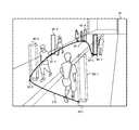
- FIG. 13is a diagram illustrating a state in which the user moves the target object on the captured image 10.
- a trajectory 170represents a trajectory in which the user has moved the target object.
- Each of the first position 30-1 to the first position 30-5represents a position on the trajectory 170.
- the first image 40-1 to the first image 40-5represent the first image 40 presented at the first position 30-1 to the first position 30-5, respectively.
- the first image 40 drawn with a dotted linerepresents the first image 40 that has already disappeared from the captured image 10
- the first image 40 drawn with a solid lineis the first image that is currently presented.
- An image 40is represented.
- the currently designated first position 30is the first position 30-5
- the first image 40-5is presented, and the first image 40-1 to the first image 40-4 are displayed. Disappeared.
- the usermoves the target object so as to pass next to a person or the like shown on the captured image 10 to determine whether or not the target object looks uncomfortable.
- Checkif there is no sense of incongruity about the size and orientation of the target object even if the target object is moved beside any person, the camera parameter acquired by the parameter acquisition unit 2040 indicates the position of the camera that captured the captured image 10 and It is considered that the position and posture approximate to the posture are represented.
- the usercan easily verify whether there is no sense of incongruity in the appearance of the target object at various positions on the captured image 10. In particular, by providing a way to see the target object by moving continuously, the legitimacy and discomfort of human vision are more emphasized and function effectively for verification.
- height informationmay be set for each stepped region in a photographed image showing a stepped region such as a staircase.
- the usercan easily verify whether there is no sense of incongruity in the appearance of the target object seamlessly including the step by moving the target object on the image as shown in the locus in FIG.
- FIG. 7is a block diagram illustrating an image processing apparatus 2000 according to the second embodiment.
- arrowsindicate the flow of information.
- each blockrepresents a functional unit configuration, not a hardware unit configuration.
- the image processing apparatus 2000includes a display unit 2020, a parameter acquisition unit 2040, a second input unit 2100, and a second display unit 2120.
- the functions of the display unit 2020 and the parameter acquisition unit 2040 of the present embodimentare the same as the functions of the display unit 2020 and the parameter acquisition unit 2040 described in the first embodiment, respectively.
- the second input unit 2100receives a point or line input for the captured image displayed by the display unit 2020.
- the second display unit 2120is arranged on a plane parallel to the ground surface based on the camera parameters, the position of the input point or line on the captured image, and the height information of the input point or line in real space.
- An image representing the point or line when mappedis displayed.
- the second display unit 2120is assumed to exist in the field of view of the camera when it is assumed that a point or line in the input captured image exists in the field of view of the camera that captured the captured image.
- An image in which the dots or lines are mapped to a plane parallel to the ground surfaceis displayed.
- the second display unit 2120may display on the same display or the like on which the captured image is displayed by the display unit 2020, or may display on a different display or the like.
- the height information of the input point or line in real spacemay be given to the second display unit 2120 in advance, or may be input to the second input unit 2100 together with these points or lines.
- the second display unit 2120maps the points or lines on the captured image onto a plane parallel to the ground surface in real space.
- a point mapping methodwill be described.
- the second display unit 2120converts the two-dimensional coordinates of the points on the captured image into three-dimensional coordinates on the real space.
- the three-dimensional coordinates on the real space corresponding to the two-dimensional coordinates on the captured imageare not uniquely determined. Therefore, the second display unit 2120 uses the input point height information. Specifically, the height information of the input point in the real space is assumed to be given height information. Accordingly, the second display unit 2120 can uniquely convert the two-dimensional coordinates on the captured image into the three-dimensional coordinates on the real space.
- the position of the input point on the plane parallel to the ground surface in the real spaceis the horizontal coordinate and the vertical coordinate (excluding the z coordinate indicating the height, x (y coordinate).
- the technique for calculating the coordinatesis a known technique. Therefore, detailed description regarding this technique is omitted.
- the principle of the process of mapping the line input on the captured image onto a plane parallel to the ground surface in real spaceis the same as the principle of the process of mapping the points described above.
- the second display unit 2120maps two or more points (for example, points at both ends) on the input line on a plane parallel to the ground surface in the real space.
- the second display unit 2120connects these mapped points with a line such as a straight line. By doing in this way, the line input on the captured image is mapped on a plane parallel to the ground surface in real space.
- FIG. 8is a diagram illustrating the captured image 10 in which a line is input via the second input unit 2100.
- a dotted line 90represents a line input to the second input unit 2100.
- the pattern 100is a line drawn on the ground surface in the real world shown in the captured image.
- the pattern 100-1 and the pattern 100-2are lines parallel to each other in the real world.
- the boundary 110is a boundary between the wall and the ground surface in the real world shown in the captured image.
- the boundary 110-1 and the boundary 110-2intersect each other vertically in the real world.
- the second display unit 2120maps the dotted line 90 on a plane parallel to the ground surface. Then, second display unit 2120 displays a state in which dotted line 90 mapped on a plane parallel to the ground surface is viewed from a direction perpendicular to the plane.
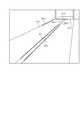
- FIG. 9is a diagram illustrating an image representing a state in which a dotted line 90 mapped to a plane representing the ground surface is viewed from a direction perpendicular to the plane.
- FIG. 9Ais a diagram in the case where the camera parameters represent positions and orientations that approximate the actual camera positions and orientations.
- the pattern 100-1 and the pattern 100-2are lines drawn parallel to each other. For this reason, in FIG.
- a projection line 120-1 in which a dotted line 90-1 is mapped on a plane representing the ground surface, and a dotted line Projection lines 120-2 in which 90-2 is mapped on the plane representing the ground surfaceare parallel or close to each other. Further, as described above, in the real world (in a place shown in the captured image), the boundary 110-3 and the boundary 110-4 intersect each other vertically. Therefore, in FIG.
- the projection line 120-3 in which the dotted line 90-3 is mapped onto the plane representing the ground surface and the projection line 120-4 in which the dotted line 90-4 is mapped onto the plane representing the ground surfaceare , Intersect each other at an angle close to or perpendicular to each other.
- FIG. 9Bis a diagram in the case where the camera parameters represent positions and orientations different from the actual camera positions and orientations.
- the projection line 120-1 and the projection line 120-2are not parallel or nearly parallel, or the projection line 120-3 and the projection line 120-4 are not perpendicular or nearly perpendicular. To do.
- the user who uses the captured image shown in FIG. 8uses the pattern 100, the boundary 110, or the like whose relation in the real world is known or easy to predict, and displays the results displayed by the second display unit 2120. By looking, it can be easily confirmed whether or not the camera parameters appropriately represent the position and orientation of the actual camera.
- the method of using the pattern on the ground surfaceis not limited to the above-described method.
- a method of inputting a plurality of points on the pattern 100-1 and confirming whether or not these plurality of points are arranged on a straight linecan be considered.
- FIG. 17is a diagram illustrating the projection line 180 of the target object presented on the captured image on the plane representing the ground surface described with reference to FIG.
- FIG. 17Ashows a case where the projection line 180 of the target object is presented when the first image representing the stationary target object is presented on the captured image (eg, FIG. 2B). It is.
- FIG. 17Bshows that when an operation for moving the target object is performed (for example, FIG. 13), the projection line 180 of the target object is moved in accordance with the movement of the target object on the captured image.
- the trajectory 190represents a trajectory of movement of the projection line 180.
- a line tracing the shapemay be input to the second input unit 2100.
- the shape of the line displayed by the second display unit 2120represents a shape close to the original shape of the traced object.
- the shape of the line displayed by the second display unit 2120is a perfect circle or a shape close to a perfect circle.
- the shape of the line presented by the second display unit 2120is a shape (for example, an ellipse) different from a perfect circle.
- FIG. 10is a diagram illustrating an image in which the position and field of view of the camera are presented together with the projection line shown in FIG.
- a camera position 150represents the position of the camera
- a field of view 160represents the field of view of the camera.
- the system setting person who handles the image processing apparatus 2000 according to the second embodimentappropriately determines the position and orientation of the actual camera by checking the positional relationship between the points and lines mapped on the plane parallel to the ground surface. Check whether it is expressed in Here, as shown in FIG. 10, when the camera position and field of view are presented together with the points and lines mapped on a plane parallel to the ground surface, the system setter etc. It becomes possible to further grasp the positional relationship with the field of view. Therefore, a system setter or the like can more easily and accurately confirm whether or not the camera parameter appropriately represents the position and orientation of the actual camera.
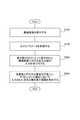
- FIG. 11is a flowchart illustrating the flow of processing executed by the image processing apparatus 2000 according to the second embodiment.
- the processes performed in steps S102 and S106are the same as the processes performed in steps S102 and S106 in FIG.
- step S ⁇ b> 202the second input unit 2100 receives a point or line input for the captured image displayed by the display unit 2020.
- step S204the second display unit 2120 displays an image representing the point or line when mapped on a plane parallel to the ground surface.
- the userinputs a line or the like in which the original shape or positional relationship can be easily specified with respect to the captured image, and the line or the like displayed by the second display unit 2120 By checking whether or not the positional relationship is satisfied, it can be easily confirmed whether or not the camera parameter appropriately represents the position and orientation of the actual camera.
- FIG. 15is a block diagram illustrating an image processing device 3000 according to the third embodiment.
- arrowsindicate the flow of information.
- each blockrepresents a functional unit configuration, not a hardware unit configuration.
- the image processing apparatus 3000includes an input unit 3020 and a presentation unit 3040.
- the input unit 3020receives an input of an operation for moving the first image presented on the captured image captured by the camera.
- the first imageis an image in which a target object having a predetermined shape and a predetermined size in real space is superimposed on a captured image based on predetermined camera parameters representing the position and orientation of the camera. For example, if the position on the captured image where the first image is presented is a position A, the first image is displayed when the position A is designated as the first position in the image processing apparatus 2000 of the first embodiment. This corresponds to the first image presented by 2080.
- the target object in the third embodimentis the same as the target object described in the first embodiment.
- the predetermined camera parameters in the third embodimentare the same as the camera parameters described in the first embodiment.
- the presenting unit 3040presents a first image representing the target object in a manner corresponding to the position on the captured image after movement based on the camera parameters.
- the method of presenting the first image corresponding to the target object to which the presenting unit 3040 is movedis the same as that described in the first embodiment “the first image 40 corresponding to the target object to which the presenting unit 2080 is moved on the captured image 10. It is the same as the “method for presenting”.
- the hardware configuration of the image processing apparatus 3000is the same as the hardware configuration of the image processing apparatus 2000.
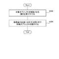
- FIG. 16is a flowchart illustrating the flow of processing executed by the image processing apparatus 3000 according to the third embodiment.
- the input unit 3020receives an input of a movement operation for the first image superimposed on the captured image.
- the presentation unit 3040presents a first image that represents the target object in a manner corresponding to the position on the captured image after movement based on the camera parameters.
- the usermoves the target object so as to pass next to a person or the like shown on the captured image 10, thereby causing the target object to move.
- the legitimacy and sense of incongruity of human visionare more emphasized and function effectively for verification.
- the image processing apparatus 2000may have the following functions.
- An image processing apparatus 2000 having the following functionsis referred to as an image processing apparatus 2000 according to the first modification.
- Note that the image processing apparatus 2000 according to the first modificationmay or may not have the functions of the image processing apparatus 2000 according to the first and second embodiments described above.
- the estimation of the camera parameteris performed by “taking a calibration pattern or its equivalent with a camera and capturing the three-dimensional coordinates of the calibration pattern in the real world and the two-dimensional calibration pattern on the captured image.
- a method of “estimating based on correspondence with coordinates”is used (Non-Patent Document 1). Specifically, the two-dimensional coordinates when the three-dimensional coordinates of the calibration pattern in the real world are projected on the captured image using the estimated camera parameters, and the two-dimensional coordinates of the calibration pattern reflected in the captured image
- the camera parametersare calculated so as to reduce the error (reprojection error) between the two. For example, there is a method of calculating an estimated value of a camera parameter so that the sum of squares of errors is minimized.
- the system setting person or the likesees only a camera parameter that is an estimation result. You will not see the above error, which is a lapse.
- the accuracy of camera parameter estimationcan be improved by showing the above-mentioned error that is in the middle of progress to the system setter or the like. For example, when the position where the error is large is concentrated toward the edge of the captured image, it is considered that the error is large due to the input error of the corresponding point or the lens distortion.
- the accuracy of the camera parametercan be improved by changing the method of selecting the calibration pattern so that the calibration pattern captured at a position within a predetermined distance from the edge of the image is not used for camera parameter estimation. it can.
- FIG. 12is a diagram illustrating a state in which information indicating an error (error information 140) is presented on the captured image.
- error information 140information indicating an error
- a personis used to obtain a calibration pattern.
- a line 130that connects the feet and heads of a substantially upright person is used as a calibration pattern.
- the error information 140 presented beside the line 130indicates a reprojection error corresponding to the line 130.
- the image processing apparatus 2000may map the calibration pattern on the ground surface and display the error in association with the calibration pattern mapped on the ground surface by the method described in the second embodiment.
- Input meansfor receiving an input of a movement operation on the captured image,
- Presenting meansfor presenting a first image representing the target object in a manner corresponding to a position on the captured image after the movement based on the camera parameter;
- An image processing apparatus2.
- the input meansreceives the movement operation by repeatedly receiving the designation of the first position on the captured image,
- the presenting meanssets the camera parameter, a predetermined shape and a predetermined size in the real space of the target object, and a second position in the real space corresponding to the first position. Based on this, when the target object is placed at the second position, a first image representing the target object on the captured image captured by the camera determined by the camera parameter is generated, and the first image on the captured image is generated.
- the presenting meansis Obtaining height information of the second position; 1. calculating the second position based on height information of the camera parameter, the first position, and the second position; An image processing apparatus according to 1. 4). 2.
- the presenting meansacquires information indicating the height of the ground surface in real space as the height information of the second position.
- the presenting meansobtains information on different heights for each of a plurality of regions on the captured image as height information on the second position.
- the target objecthas a planar shape.
- Second input meansfor receiving an input of a point or a line with respect to the captured image; Based on the camera parameter, the position of the point or line on the captured image, and the height information of the point or line in real space, the point or line when mapped on a plane parallel to the ground surface
- Second display meansfor displaying a second image to be represented; Having 1. To 6.
- Input meansfor accepting designation of the first position on the captured image; Based on predetermined camera parameters representing the position and orientation of the camera, a predetermined shape and size in the real space of the target object, and a second position in the real space corresponding to the first position, the target object is Presenting means for presenting, at the first position on the captured image, a first image representing the target object on the captured image captured by the camera determined by the camera parameters when placed at two positions; An image processing apparatus. 9.
- the input meansaccepts designation of a plurality of first positions,
- the presenting meanspresents a first image representing a plurality of target objects corresponding to the plurality of first positions at a corresponding first position on the captured image.
- An image processing apparatusaccording to 1. 10.
- the input meansrepeatedly receives the designation of the first position.
- the presentation meansis the object placed at the second position in the real space corresponding to the first position.
- 7.Generate a first image representing the object and present it at the first position on the captured image.
- An image processing apparatusaccording to 1.
- Display meansfor displaying a first image representing the point or line when An image processing apparatus.
- An image processing method executed by a computerA first image representing a target object having a predetermined shape and a predetermined size in real space superimposed on a captured image captured by a camera based on predetermined camera parameters indicating the position and orientation of the camera.
- An image processing methodexecuted by a computer, A first image representing a target object having a predetermined shape and a predetermined size in real space superimposed on a captured image captured by a camera based on predetermined camera parameters indicating the position and orientation of the camera.
- the input stepaccepts the movement operation by repeatedly accepting designation of the first position on the captured image
- the camera parameter, a predetermined shape and a predetermined size in the real space of the target object, and a second position in the real space corresponding to the first positionare set. Based on this, when the target object is placed at the second position, a first image representing the target object on the captured image captured by the camera determined by the camera parameter is generated, and the first image on the captured image is generated.
- An image processing method described in 1. 14includes Obtaining height information of the second position; 12. Calculate the second position based on height information of the camera parameter, the first position, and the second position.
- the presenting stepinformation indicating the height of the ground surface in real space is acquired as the height information of the second position.
- An image processing method described in 1. 16information on different heights for each of a plurality of regions on the captured image is acquired as height information on the second position.
- the target objecthas a planar shape. To 16. The image processing method according to any one of the above. 18.
- a second input stepfor receiving an input of a point or a line with respect to the captured image; Based on the camera parameter, the position of the point or line on the captured image, and the height information of the point or line in real space, the point or line when mapped on a plane parallel to the ground surface
- An image processing method executed by a computerAn input step for accepting designation of the first position on the captured image; Based on predetermined camera parameters representing the position and orientation of the camera, a predetermined shape and size in the real space of the target object, and a second position in the real space corresponding to the first position, the target object is A presenting step of presenting, at the first position on the captured image, a first image representing the target object on the captured image captured by the camera parameter determined by the camera parameter when placed at two positions; An image processing method. 20.
- the input stepaccepts designation of a plurality of first positions;
- the presenting steppresents a first image representing a plurality of target objects corresponding to the plurality of first positions at a corresponding first position on the captured image.
- the input steprepeatedly receives the designation of the first position.
- the presentation stepwhen a certain first position is designated, is the object placed at the second position in the real space corresponding to the first position. 18.
- An image processing method executed by a computerAn input step for receiving an input of a point or a line with respect to a captured image captured by the camera; Mapping on a plane parallel to the ground surface based on predetermined camera parameters representing the position and orientation of the camera, the position of the point or line on the captured image, and the height information of the point or line in real space
Landscapes
- Engineering & Computer Science (AREA)
- Physics & Mathematics (AREA)
- General Physics & Mathematics (AREA)
- Multimedia (AREA)
- Signal Processing (AREA)
- Theoretical Computer Science (AREA)
- Computer Hardware Design (AREA)
- Computer Graphics (AREA)
- General Engineering & Computer Science (AREA)
- Software Systems (AREA)
- Business, Economics & Management (AREA)
- Emergency Management (AREA)
- Human Computer Interaction (AREA)
- Computer Vision & Pattern Recognition (AREA)
- Health & Medical Sciences (AREA)
- Biomedical Technology (AREA)
- General Health & Medical Sciences (AREA)
- Studio Devices (AREA)
- Closed-Circuit Television Systems (AREA)
- Image Processing (AREA)
- Processing Or Creating Images (AREA)
- Image Analysis (AREA)
Abstract
Description
Translated fromJapanese本発明は画像処理技術に関する。The present invention relates to image processing technology.
施設等を監視する方法の一つとして、その施設等に設置された監視カメラの映像を利用する方法がある。ここで、監視カメラの映像に写っている人又は物の実際のサイズや位置は、カメラの位置及び姿勢に関する情報(以下、カメラパラメータ)とその映像(画像)に写っている人又は物の画像上のサイズや位置を用いて計算することができる。このような計算により、例えば監視カメラの映像に重要人物(事件の犯人など)が写っている場合に、監視カメラの映像を用いてその人物の身長などを把握することが可能となる。As one method of monitoring facilities, there is a method of using images from surveillance cameras installed in the facilities. Here, the actual size or position of a person or thing shown in the video of the surveillance camera is information on the position and orientation of the camera (hereinafter referred to as camera parameters) and the image of the person or thing shown in the video (image). It can be calculated using the size and position above. With this calculation, for example, when an important person (such as a criminal of an incident) is shown in the video of the surveillance camera, the height of the person can be grasped using the video of the surveillance camera.
上述の目的等で利用するカメラパラメータは、例えばキャリブレーションによって推定される。非特許文献1は、カメラでキャリブレーションパターンを撮影し、実世界におけるキャリブレーションパターンの3次元座標と、撮像した画像上におけるキャリブレーションパターンの2次元座標との対応関係から、カメラの位置及び姿勢を示すカメラパラメータ(カメラの回転と並進)を推定する方法を開示している。The camera parameters used for the above-mentioned purposes are estimated by calibration, for example. Non-Patent Document 1 captures a calibration pattern with a camera. From the correspondence between the three-dimensional coordinates of the calibration pattern in the real world and the two-dimensional coordinates of the calibration pattern on the captured image, the position and orientation of the camera are described. Discloses a method for estimating camera parameters (camera rotation and translation).
また、推定済みのカメラパラメータを入手して利用する場合もある。例えば、過去に対象のカメラについてキャリブレーションを行って算出しておいたカメラパラメータを入手したり、そのカメラを設置した際の位置及び姿勢などの情報に基づいて定義されたカメラパラメータを入手したりすることがある。In some cases, estimated camera parameters are obtained and used. For example, obtain camera parameters that have been calculated by calibrating the target camera in the past, or obtain camera parameters defined based on information such as position and orientation when the camera was installed There are things to do.
カメラパラメータが対象のカメラの位置及び姿勢などを適切に表せているとは限らない。例えばキャリブレーションによってカメラパラメータを算出する方法では、対応点の入力誤差やレンズ歪み等の原因により、実際のカメラの位置又は姿勢とは異なる位置及び姿勢を表すカメラパラメータが算出されうる。また推定済みのカメラパラメータを入手する場合も、そのカメラパラメータが適切なものであるか否かは分からない。例えば、時間の経過に伴ってカメラの位置や姿勢が変化してしまう可能性があるため、過去に推定したカメラパラメータと現在のカメラの位置又は姿勢とは異なっている場合がある。* Camera parameters do not always represent the position and orientation of the target camera. For example, in the method of calculating camera parameters by calibration, camera parameters representing positions and orientations different from the actual camera positions or orientations may be calculated due to input errors of corresponding points, lens distortion, and the like. Also, when obtaining estimated camera parameters, it is not known whether the camera parameters are appropriate. For example, since the position and orientation of the camera may change with time, the camera parameter estimated in the past may be different from the current position or orientation of the camera.
カメラパラメータが対象のカメラの位置及び姿勢などを正しく表せていないと、例えば前述した監視カメラの映像に写っている重要人物の身長などを算出する場合に算出結果に誤りが生じるといった問題がある。If the camera parameters do not correctly represent the position and orientation of the target camera, for example, when calculating the height of an important person shown in the video of the monitoring camera described above, there is a problem that an error occurs in the calculation result.
本発明の目的は、以上の課題に鑑みてなされたものである。本発明の目的は、カメラパラメータが適切であるか否かを容易に確認できる技術を提供することである。The object of the present invention has been made in view of the above problems. The objective of this invention is providing the technique which can confirm easily whether a camera parameter is appropriate.
本発明が提供する第1の画像処理装置は、カメラによって撮影された撮像画像に対して、当該カメラの位置及び姿勢を表す所定のカメラパラメータの基で重畳された、実空間上における所定形状及び所定サイズが定められた対象オブジェクトを表す第1画像に対する、前記撮像画像上における移動の操作の入力を受け付ける入力手段と、前記カメラパラメータの基で、前記移動後の前記撮像画像上の位置に対応する見え方で前記対象オブジェクトを表す第1画像を提示する提示手段と、を有する。A first image processing apparatus provided by the present invention includes a predetermined shape in real space superimposed on a captured image captured by a camera based on predetermined camera parameters representing the position and orientation of the camera, and Corresponding to the position on the captured image after the movement based on the input means for receiving the input of the movement operation on the captured image with respect to the first image representing the target object having a predetermined size. Presenting means for presenting a first image representing the target object in a visible manner.
本発明が提供する第2の画像処理装置は、カメラによって撮像された撮像画像を表示する表示手段と、カメラの位置及び姿勢を表すカメラパラメータを取得するパラメータ取得手段と、前記撮像画像上の第1位置の指定を受け付ける入力手段と、前記カメラパラメータ、対象オブジェクトの実空間上における所定形状及び所定サイズ、並びに前記第1位置に対応する実空間上の第2位置に基づいて、前記対象オブジェクトを前記第2位置に置いた場合に前記カメラパラメータによって定まるカメラに写る前記撮像画像上の前記対象オブジェクトを表す第1画像を、前記撮像画像上の前記第1位置に提示する提示手段と、を有する。A second image processing apparatus provided by the present invention includes a display unit that displays a captured image captured by a camera, a parameter acquisition unit that acquires a camera parameter indicating the position and orientation of the camera, and a second unit on the captured image. Based on an input means for receiving designation of one position, the camera parameter, a predetermined shape and a predetermined size in the real space of the target object, and a second position in the real space corresponding to the first position, the target object Presenting means for presenting, at the first position on the captured image, a first image representing the target object on the captured image captured by the camera parameter determined by the camera parameter when placed at the second position; .
本発明が提供する第3の画像処理装置は、カメラによって撮像された撮像画像を表示する第1表示手段と、カメラの位置及び姿勢を表すカメラパラメータを取得するパラメータ取得手段と、前記撮像画像に対する点又は線の入力を受け付ける入力手段と、前記カメラパラメータ、前記点又は線の前記撮像画像上の位置、及び前記点又は線の実空間上の高さ情報に基づいて、地表面と平行な面上にマッピングした場合の前記点又は線を表す第1画像を表示する第2表示手段と、を有する。A third image processing apparatus provided by the present invention includes a first display unit that displays a captured image captured by a camera, a parameter acquisition unit that acquires a camera parameter that represents the position and orientation of the camera, and the captured image A plane parallel to the ground surface based on input means for receiving the input of a point or line, the camera parameter, the position of the point or line on the captured image, and the height information of the point or line in real space Second display means for displaying a first image representing the point or line when mapped on top.
本発明が提供する第1の画像処理方法は、コンピュータによって実行される。当該画像処理方法は、カメラによって撮影された撮像画像に対して、当該カメラの位置及び姿勢を表す所定のカメラパラメータの基で重畳された、実空間上における所定形状及び所定サイズが定められた対象オブジェクトを表す第1画像に対する、前記撮像画像上における移動の操作の入力を受け付ける入力ステップと、前記カメラパラメータの基で、前記移動後の前記撮像画像上の位置に対応する見え方で前記対象オブジェクトを表す第1画像を提示する提示ステップと、を有する。The first image processing method provided by the present invention is executed by a computer. The image processing method is an object in which a predetermined shape and a predetermined size in a real space are superimposed on a captured image captured by a camera based on predetermined camera parameters representing the position and orientation of the camera. An input step for receiving an input of a movement operation on the captured image with respect to the first image representing the object, and the target object in a manner corresponding to the position on the captured image after the movement based on the camera parameter Presenting a first image representing the first image.
本発明が提供する第2の画像処理方法は、コンピュータによって実行される。当該画像処理方法は、カメラによって撮像された撮像画像を表示する表示ステップと、カメラの位置及び姿勢を表すカメラパラメータを取得するパラメータ取得ステップと、前記撮像画像上の第1位置の指定を受け付ける入力ステップと、前記カメラパラメータ、対象オブジェクトの実空間上の所定形状及び所定サイズ、並びに前記第1位置に対応する実空間上の第2位置に基づいて、前記対象オブジェクトを前記第2位置に置いた場合に前記カメラパラメータによって定まるカメラに写る前記撮像画像上の前記対象オブジェクトを表す第1画像を、前記撮像画像上の前記第1位置に提示する提示ステップと、を有する。The second image processing method provided by the present invention is executed by a computer. The image processing method includes a display step for displaying a captured image captured by a camera, a parameter acquisition step for acquiring a camera parameter representing the position and orientation of the camera, and an input for receiving designation of a first position on the captured image. The target object is placed at the second position based on the step, the camera parameter, the predetermined shape and size of the target object in the real space, and the second position in the real space corresponding to the first position. A presentation step of presenting a first image representing the target object on the captured image captured by the camera determined by the camera parameter at the first position on the captured image.
本発明が提供する第3の画像処理方法は、コンピュータによって実行される。当該画像処理方法は、カメラによって撮像された撮像画像を表示する第1表示ステップと、カメラの位置及び姿勢を表すカメラパラメータを取得するパラメータ取得ステップと、前記撮像画像に対する点又は線の入力を受け付ける入力ステップと、前記カメラパラメータ、前記点又は線の前記撮像画像上の位置、及び前記点又は線の実空間上の高さ情報に基づいて、地表面と平行な面上にマッピングした場合の前記点又は線を表す第1画像を表示する第2表示ステップと、を有する。The third image processing method provided by the present invention is executed by a computer. The image processing method receives a first display step for displaying a captured image captured by a camera, a parameter acquisition step for acquiring a camera parameter representing the position and orientation of the camera, and input of a point or a line with respect to the captured image. Based on the input step, the camera parameter, the position of the point or line on the captured image, and the height information of the point or line in real space, the mapping is performed on a plane parallel to the ground surface. And a second display step for displaying a first image representing a point or line.
本発明が提供するプログラムは、コンピュータを、本発明が提供する第1の画像処理装置、第2の画像処理装置、又は第3の画像処理装置として動作させる。The program provided by the present invention causes a computer to operate as the first image processing apparatus, the second image processing apparatus, or the third image processing apparatus provided by the present invention.
本発明によれば、カメラパラメータが適切であるか否かを容易に確認できる技術が提供される。According to the present invention, a technique for easily confirming whether or not a camera parameter is appropriate is provided.
上述した目的、およびその他の目的、特徴および利点は、以下に述べる好適な実施の形態、およびそれに付随する以下の図面によってさらに明らかになる。The above-described object and other objects, features, and advantages will be further clarified by a preferred embodiment described below and the following drawings attached thereto.
以下、本発明の実施の形態について、図面を用いて説明する。尚、すべての図面において、同様な構成要素には同様の符号を付し、適宜説明を省略する。Hereinafter, embodiments of the present invention will be described with reference to the drawings. In all the drawings, the same reference numerals are given to the same components, and the description will be omitted as appropriate.
[実施形態1]
図1は、実施形態1に係る画像処理装置2000を例示するブロック図である。図1において、矢印は情報の流れを表している。さらに、図1において、各ブロックは、ハードウエア単位の構成ではなく、機能単位の構成を表している。[Embodiment 1]
FIG. 1 is a block diagram illustrating an
画像処理装置2000は、表示部2020、パラメータ取得部2040、入力部2060、及び提示部2080を有する。The
表示部2020は、カメラによって撮像された撮像画像を表示する。パラメータ取得部2040は、カメラの位置及び姿勢などを表すカメラパラメータを取得する。なお、カメラパラメータにはカメラの位置及び姿勢以外のパラメータが含まれてもよい。カメラの位置及び姿勢以外のカメラパラメータについては後述する。
入力部2060は、撮像画像上の第1位置の指定を受け付ける。提示部2080は、第1位置に対応する実空間上の第2位置に対象オブジェクトを置いた場合に上記カメラパラメータによって定まるカメラに写る、撮像画像上の対象オブジェクトを表す第1画像を生成する。言い換えれば、第1画像は、上記カメラパラメータによって定まるカメラの視点から見て、対象オブジェクトがどのように見えるのかを表す画像である。また、実空間上の第2位置は、カメラパラメータと第1位置と第2位置の高さ情報から求めることができる。ここで、「対象オブジェクトを第2位置に置く」とは、対象オブジェクトが、撮像画像上の第1位置に対応する実空間上の位置(第2位置)に存在すると仮定することを意味する。提示部2080は、上記カメラパラメータ、対象オブジェクトの実空間上における所定形状及び所定サイズ、並びに第2位置を用いて第1画像を生成する。さらに、提示部2080は、生成した第1画像を撮像画像上の第1位置に提示する。対象オブジェクトは、平面形状又は立体形状を有する仮想物である。対象オブジェクトに設定される所定サイズ及び所定形状は、現実世界を想定したサイズ及び形状である。これら所定サイズ及び所定形状は、ユーザにより入力されてもよいし、予め画像処理装置2000の内部又は外部に記憶されていてもよい。The
図2を用いて具体的に説明する。図2は、画像処理装置2000が所定オブジェクトを撮像画像上に提示した様子を例示する図である。図2において、所定オブジェクトは直方体20である。図2(a)は、直方体20を適当な角度から見た様子を表している。図2(a)に示すように、直方体20のサイズは、横及び縦の長さが 30cm であり、高さが 170cm である。本例における直方体20は、平均的な人の形状及びサイズを簡略化したオブジェクトである。This will be specifically described with reference to FIG. FIG. 2 is a diagram illustrating a state in which the
図2(b)は、画像処理装置2000が直方体20を撮像画像10上に提示した図である。第1位置30は、入力部2060に対して入力された第1位置を表す。提示部2080は、第1位置30に第1画像40を提示する。第1画像40は、実世界における第1位置30に相当する位置に置かれた直方体20をカメラパラメータによって定まるカメラによって撮像した場合に、そのカメラに写る直方体20を擬似的に表す画像である。FIG. 2B is a diagram in which the
<処理の流れ>
図3は、実施形態1の画像処理装置2000が実行する処理の流れを例示するフローチャートである。ステップS102において、表示部2020は、カメラによって撮像された撮像画像を表示する。ステップS104において、入力部2060は、撮像画像上の第1位置の指定を受け付ける。ステップS106において、パラメータ取得部2040は、カメラの位置及び姿勢などを表すカメラパラメータを取得する。ステップS108において、提示部2080は第1画像を生成する。前述したように、第1画像は、第2位置に置いた場合に上記カメラパラメータによって定まるカメラに写るときの、撮像画像上における対象オブジェクトを表す。そしてステップS110において、提示部2080は、生成した第1画像を撮像画像上の第1位置に提示する。<Process flow>
FIG. 3 is a flowchart illustrating the flow of processing executed by the
なお、図3に示した処理の流れは一例であり、画像処理装置2000が実行する処理の流れは図3に示した流れに限定されない。例えば、第1位置の入力を受け付ける処理(ステップS104)よりも先にカメラパラメータを取得する処理(ステップS106)が行われてもよい。Note that the flow of processing shown in FIG. 3 is an example, and the flow of processing executed by the
<作用・効果>
本実施形態によれば、提示部2080によって提示されるオブジェクトを画像処理装置2000のユーザが見ることにより、カメラパラメータが、表示部2020よって表示される撮像画像を撮像したカメラ(以下、実カメラ)の位置及び姿勢などを適切に表しているか否かを容易に確かめることができる。以下、図4を用いて詳しく説明する。<Action and effect>
According to the present embodiment, a camera that captures a captured image displayed by the
図4は、提示部2080によって第1画像が提示された撮像画像を例示する図である。図4(a)は、パラメータ取得部2040によって取得されたカメラパラメータが実カメラの位置及び姿勢と近似する位置及び姿勢を表している場合の図である。一方、図4(b)は、パラメータ取得部2040によって取得されたカメラパラメータが実カメラの位置及び姿勢と異なる位置及び姿勢を表している場合の図である。なお図4における対象オブジェクトは、図2の場合と同様に、高さが 170cm、かつ縦及び横の長さがいずれも 30cm である直方体である。FIG. 4 is a diagram illustrating a captured image in which the first image is presented by the
提示部2080によって提示される第1画像は、撮像画像に写っている場所に置かれた対象オブジェクトが、カメラパラメータによって表される位置及び姿勢で設置されているカメラによって撮像されたかのように、撮像画像上に提示される。そのため、カメラパラメータが実カメラの位置及び姿勢と近似する位置及び姿勢を表している場合、撮像画像上に写っている人や物などと第1画像を見比べた場合に、大きさや角度による見え方などに違和感がない。例えば、対象オブジェクトの高さは 170cm であるため、対象オブジェクトと人とを比較した場合に、大体同じ程度の高さになると考えられる。The first image presented by the
図4では、撮像画像10に写っている人の横が第1位置として指定されているため、人の横に第1画像40が提示されている。そして、図4(a)では、いずれの位置においても、人と第1画像40が表す直方体とのサイズがほぼ同じであり、違和感がない。また、図4(a)では、人や壁などが、正面斜め上から見下ろされて写っているのと同様に、各第1画像40によって表される直方体も正面斜め上から見下ろされているようになっており、各直方体の角度による見え方についても違和感が無い。In FIG. 4, since the side of the person shown in the captured
これに対し、図4(b)では、第1画像40によって表される直方体のサイズや角度による見え方について違和感がある。例えば、第1画像40-10が表す直方体の高さは人の2倍近い高さになっており、第1画像40-10は撮像画像10-2に写っている場所に置かれた高さ 170cm のオブジェクト(直方体20)を表しているとは言えない。また、撮像画像10-1に提示されている各第1画像40が表す直方体と異なり、撮像画像10-2では全ての直方体について上面が見えており、近くから見下ろしたような見え方となっている。このように、第1画像40によって表される各直方体のサイズ及び角度から、図4(b)におけるカメラパラメータによって表されるカメラの視線方向の俯角は、実カメラの視線方向の俯角よりも大きくなってしまっていると予想できる。On the other hand, in FIG. 4B, there is a sense of incongruity regarding how the rectangular parallelepiped represented by the
なお、図4に示すように、ユーザは複数の第1位置を指定して、複数の対象オブジェクトを一つの撮像画像内に配置することができる。As shown in FIG. 4, the user can designate a plurality of first positions and place a plurality of target objects in one captured image.
以上のように、本実施形態の画像処理装置2000によれば、画像処理装置2000を利用するユーザが提示部2080によって提示された第1画像と撮像画像を見比べることにより、パラメータ取得部2040によって取得されたカメラパラメータが、撮像画像を撮像したカメラの位置及び姿勢と近似する位置及び姿勢を表しているか否かを容易に把握することができる。撮像画像を撮像したカメラの位置及び姿勢と近似する位置及び姿勢を表していることが確認できれば、ユーザは、そのカメラパラメータと監視カメラの映像との組み合わせを利用してよいと判断できる。逆に、撮像画像を撮像したカメラの位置及び姿勢と近似する位置及び姿勢を表していないことが確認できれば、カメラパラメータの推定を再度行ったり、実カメラの位置や姿勢を修正したりするなどといった対処を行うことができる。As described above, according to the
以下、本実施形態の画像処理装置2000について、さらに詳細に説明する。Hereinafter, the
<ハードウエア構成例>
画像処理装置2000の各機能構成部は、各機能構成部を実現するハードウエア構成要素(例:ハードワイヤードされた電子回路など)で実現されてもよいし、ハードウエア構成要素とソフトウエア構成要素との組み合わせ(例:電子回路とそれを制御するプログラムの組み合わせなど)で実現されてもよい。<Hardware configuration example>
Each functional component of the
図5は、画像処理装置2000のハードウエア構成を例示するブロック図である。画像処理装置2000は、バス1020、プロセッサ1040、メモリ1060、ストレージ1080、及び入出力インタフェース1100を有する。バス1020は、プロセッサ1040、メモリ1060、ストレージ1080、及び入出力インタフェース1100が、相互にデータを送受信するためのデータ伝送路である。ただし、プロセッサ1040などを互いに接続する方法は、バス接続に限定されない。プロセッサ1040は、例えば CPU (Central Processing Unit) や GPU (Graphics Processing Unit) などの演算処理装置である。メモリ1060は、例えば RAM (Random Access Memory) や ROM (Read Only Memory) などのメモリである。ストレージ1080は、例えばハードディスク、SSD (Solid State Drive)、又はメモリカードなどの記憶装置である。また、ストレージ1080は、RAM や ROM 等のメモリであってもよい。入出力インタフェース1100は、画像処理装置2000が入力デバイスや外部の装置等との間でデータを送受信するための入出力インタフェースである。例えば画像処理装置2000は、入出力インタフェース1100を介して、撮像画像や第1位置などを取得する。また例えば画像処理装置2000は、入出力インタフェースを介して、第1画像を提示した撮像画像を出力する。FIG. 5 is a block diagram illustrating a hardware configuration of the
ストレージ1080は、画像処理装置2000の機能を実現するためのプログラムを記憶している。具体的には、表示部2020、パラメータ取得部2040、入力部2060、及び提示部2080の機能をそれぞれ実現するプログラムモジュールを記憶している。プロセッサ1040は、これら各プログラムモジュールを実行することで、表示部2020、パラメータ取得部2040、入力部2060、及び提示部2080の機能をそれぞれ実現する。ここでプロセッサ1040は、上記各モジュールを実行する際、これらのモジュールをメモリ1060上に読み出してから実行してもよいし、メモリ1060上に読み出さずに実行してもよい。The
画像処理装置2000のハードウエア構成は図5に示した構成に限定されない。例えば、各プログラムモジュールはメモリ1060に格納されてもよい。この場合、画像処理装置2000は、ストレージ1080を備えていなくてもよい。The hardware configuration of the
<カメラパラメータの詳細>
前述したように、カメラパラメータは、カメラの位置及び姿勢以外のパラメータを含んでもよい。例えばカメラパラメータには、焦点距離、レンズ歪み、又は画像中心の座標など、カメラの内部的な特徴を表す内部パラメータが含まれる。なお、カメラの位置及び姿勢は、カメラの外部的な特徴を表す外部パラメータである。カメラパラメータは、撮像画像上の2次元座標と、実空間上の3次元座標とを対応づけることにより算出できる。<Details of camera parameters>
As described above, the camera parameters may include parameters other than the position and orientation of the camera. For example, the camera parameters include internal parameters representing internal characteristics of the camera, such as focal length, lens distortion, or image center coordinates. The position and orientation of the camera are external parameters that represent the external characteristics of the camera. The camera parameter can be calculated by associating the two-dimensional coordinates on the captured image with the three-dimensional coordinates on the real space.
カメラパラメータを用いることにより、撮像画像上の2次元座標と、実空間上の3次元座標とを相互に変換することができる。ただし、撮像画像上の2次元座標だけでは、その2次元座標に対応する実空間上の3次元座標が一意に定まらない。撮像画像上の2次元座標に対応する実空間上の3次元座標を一意に定めるためには、例えばこの3次元座標の x 座標、y 座標、又は z 座標のいずれかを特定する必要がある。本実施形態の画像処理装置2000では、実空間上の第2位置の高さ情報( z 座標)を特定することにより、撮像画像上の第1位置に対応する実空間上の第2位置を一意に定めている。なお本実施形態では、カメラ真下の地表面に実空間上の原点を設定し、地表面と並行な横方向、縦方向に x 座標、y 座標を設定し、地表面と垂直な方向に z 座標を設定して説明を進めている。ここで、カメラパラメータを用いて画像上の座標と実空間上の座標とを相互に変換する技術は既知の技術であり、例えば非特許文献1に記載されている。そのため、この技術に関するこれ以上の詳細な説明は省略する。By using camera parameters, two-dimensional coordinates on the captured image and three-dimensional coordinates on the real space can be mutually converted. However, the three-dimensional coordinates in the real space corresponding to the two-dimensional coordinates are not uniquely determined only by the two-dimensional coordinates on the captured image. In order to uniquely determine the three-dimensional coordinate in the real space corresponding to the two-dimensional coordinate on the captured image, it is necessary to specify, for example, one of the x coordinate, y coordinate, or z coordinate of the three-dimensional coordinate. In the
なお、パラメータ取得部2040がカメラパラメータを取得する方法は様々である。例えばパラメータ取得部2040は、外部の装置から送信されるカメラパラメータを受信する。また例えば、パラメータ取得部2040は、手動によるカメラパラメータの入力を受け付ける。さらに例えば、パラメータ取得部2040は、カメラパラメータを記憶している記憶装置からカメラパラメータを読み出す。Note that there are various methods by which the
<表示部2020の詳細>
表示部2020は、ディスプレイ等の表示画面に撮像画像を表示する。ここで、この表示画面は据え置き型のディスプレイであってもよいし、携帯端末等に備えられている可搬型のディスプレイであってもよい。<Details of
The
<第1位置の入力方法の詳細>
入力部2060は、撮像画像上の位置を特定できる様々な方法で、第1位置の指定を受け付けることができる。例えば、入力部2060は、マウス等の入力デバイスによって撮像画像上の任意の位置を指定する操作(クリック操作など)を受け付ける。また、撮像画像がタッチパネル上に表示されている場合、入力部2060は、撮像画像上の任意の位置に対するタッチ入力等を受け付ける。また入力部2060は、撮像画像上の位置を表す座標の入力を受け付けてもよい。<Details of the first position input method>
The
<対象オブジェクトの詳細>
対象オブジェクトは、例えば予め定められた実空間上のサイズ及び形状を持つオブジェクトである。例えば前述した、「高さ 170cm、かつ縦及び横の長さが 30cm である直方体」という所定の対象オブジェクトを定義する情報が画像処理装置2000の内部又は外部に予め格納されている。この場合、提示部2080は、この所定の対処オブジェクトを利用する。<Details of the target object>
The target object is, for example, an object having a predetermined size and shape in real space. For example, the above-described information defining a predetermined target object “a rectangular parallelepiped having a height of 170 cm and a vertical and horizontal length of 30 cm” is stored in advance or inside the
また画像処理装置2000は、対象オブジェクトを定義する情報の入力を受け付ける機能を有していてもよい。この場合、対象オブジェクトの実空間上の形状及びサイズの双方を表す情報を受け付けてもよいし、形状又はサイズのいずれかのみを表す情報を受け付けてもよい。後者の場合、例えば対象オブジェクトの形状は予め直方体という形状に定めておき、サイズ(縦及び横の長さ、並びに高さ)の指定をユーザから受け付ける。Also, the
なお対象オブジェクトの形状は、直方体に限定されない。例えば対象オブジェクトは錐体や球体であってもよい。また対象オブジェクトは、アバタなど、人や動物などの形状を表すオブジェクトであってもよい。Note that the shape of the target object is not limited to a rectangular parallelepiped. For example, the target object may be a cone or a sphere. The target object may be an object representing a shape of a person or an animal such as an avatar.
また、対象オブジェクトは平面形状でもよい。図6は、平面形状の対象オブジェクトを表す第1画像40を撮像画像10上に提示する様子を例示する図である。この場合、例えばユーザは、平面の縦及び横の長さを指定する。カメラパラメータが実カメラの位置及び姿勢などを適切に表している場合、提示部2080によって提示される第1画像は地表面と平行になる。ユーザは、提示部2080によって提示される第1画像40と撮像画像10に写っている地表面とを比較し、第1画像40によって表されている平面が地表面と平行になっているか否かを見ることで、カメラパラメータが実カメラの位置及び姿勢などを適切に表しているか否かを容易に確認できる。また、平面のサイズを指定している為、撮影画像内に写り込む既知のサイズの物体等と、画像上の見えやサイズを比較して違和感を確かめることで、カメラパラメータが実カメラの位置及び姿勢などを適切に表しているか否かを容易に確認できる。Also, the target object may be a planar shape. FIG. 6 is a diagram illustrating a state in which the
<提示部2080の詳細>
前述したように、提示部2080は、第2位置に置いた場合の対象オブジェクトが、上記カメラパラメータによって定まるカメラに写るときの、撮像画像上の対象オブジェクトを表す画像を生成する。例えば提示部2080は、以下のような処理を行う。<Details of the
As described above, the
まず提示部2080は、対象画像上の第1位置に対応する、実空間上の第2位置を算出する。ここで前述したように、対象画像上の第1位置(2次元座標)だけでは、第1位置に対応する実空間上の第2位置(3次元座標)が一意に定まらない。そこで提示部2080は、第2位置の高さを表す情報(第2位置の z 座標)を取得する。例えば第2位置の高さ情報は、実空間上における地表面の高さ(z = 0)を表す。このように第2位置の高さ情報を特定することで、対象画像上の第1位置に対応する実空間上の位置が一意に定まる。ここで、提示部2080は、第1位置を表す2次元座標、第2位置の高さ情報、及びカメラパラメータを用いることで、第2位置の3次元座標を算出する。前述したように、これらの情報を用いることで、撮像画像上の2次元座標を実空間上の3次元座標に変換することができる。なお、第2位置の高さ情報は、予め提示部2080に与えられていてもよいし、外部から入力されてもよい。または、第2位置の高さ情報は、対象画像内における複数の領域毎に異なる高さとして設定されてもよい。First, the
次に提示部2080は、撮像画像上に提示する対象オブジェクトを表す第1画像を生成する。例えば対象オブジェクトが直方体や錐体の場合、提示部2080は、第1画像を生成するために、撮像画像上に提示する対象オブジェクトの各頂点の座標を算出する。具体的には、提示部2080は、カメラパラメータを用いて、対象オブジェクトを実空間上の第2位置に置いた場合における各頂点の3次元座標を、撮像画像上における各頂点の2次元座標に変換する。そして、提示部2080は、各頂点を直線などで結ぶことにより、第1画像を生成する。Next, the
なお、実空間に置く対象オブジェクトの角度は任意である。例えば提示部2080は、実空間を表す xyz 空間において、対象オブジェクトの横の辺が x 軸と平行であり、縦の辺が y 軸と平行であり、高さ方向の辺が z 軸と平行であるように、対象オブジェクトが第2位置に置かれたとみなす。これらの辺の方向は、予め定められていてもよいし、ユーザによる指定を受け付けてもよい。例えば、図6の撮像画像10において、平面形状の対象オブジェクトを利用する場合、縦方向の辺を地表面上のラインに合わせるようにすることで、対象オブジェクトと地表面とが平行であるか否かの判断をより容易に行えるようになる。このほか、例えば、対象オブジェクトに実空間上における所定幅の格子が描かれている場合、対象オブジェクトの縦方向の辺を大きさが既知な床面のタイルのラインなどに合わせることでタイルの大きさを測ることができる。大きさを確認することで判断をより容易に行えるようになる。そこで例えば、画像処理装置2000は、ユーザが、マウス等を用いて撮像画像10上に提示している対象オブジェクトを回転できるようにする。例えば画像処理装置2000は、撮像画像10上に提示されている対象オブジェクト又はその周辺がマウス等でドラッグされた場合、そのドラッグの向きに応じて、対象オブジェクトを回転させる向きを決定する。例えば左方向にドラッグされた場合の回転方向を時計回りとし、右方向にドラッグされた場合の回転方向を反時計回りとする。また画像処理装置2000は、そのドラッグの距離に応じて、対象オブジェクトを回転させる角度を決定する。この場合、ドラッグの距離と回転させる角度との関係を予め定義しておく。そして、画像処理装置2000は、第2位置を通る直線(例えば z 軸に平行な直線)を回転軸とし、決定した向き及び角度で対象オブジェクトを回転させる。そしてユーザは、対象オブジェクトの縦の辺が地表面上のラインに沿うようにした後、撮像画像10上の対象オブジェクトと地表面とを比較する。なお、第2位置は、対象オブジェクトの内部の点に限定されず、外部にあってもよい。Note that the angle of the target object placed in the real space is arbitrary. For example, in the xyz space representing the real space, the
さらに提示部2080は、対象オブジェクトを撮像画像10上で移動させる操作を受け付けてもよい。例えばユーザは、「マウスの右ボタンで撮像画像10上をドラッグする」などの操作により、撮像画像10上で対象オブジェクトを移動させる。このとき入力部2060は、移動するマウスポインタの位置を、前述の第1位置として繰り返し取得する。例えばこの取得は、所定の時間間隔で行われる。提示部2080は、入力部2060によって新たに取得された撮像画像10上の第1位置に、その第1位置及び固定的に得られるカメラパラメータ及び第2位置の高さ情報に基づいて新たに生成された第1画像40を提示する。さらに提示部2080は、この第1位置よりも前に取得された第1位置に提示していた第1画像40を撮像画像10上から削除する。こうすることでユーザの視点からは、撮像画像10に写っている空間上を対象オブジェクトが移動しているように見える。Further, the
図13は、ユーザが撮像画像10上で対象オブジェクトを移動させる様子を例示する図である。図13において、軌跡170は、ユーザが対象オブジェクトを移動させた軌跡を表す。第1位置30-1から第1位置30-5はそれぞれ、軌跡170上の位置を表す。第1画像40-1から第1画像40-5はそれぞれ、第1位置30-1から第1位置30-5において提示される第1画像40を表す。ここで、点線で描かれている第1画像40は、既に撮像画像10上から消えている第1画像40を表し、実線で描かれている第1画像40は、現在提示されている第1画像40を表す。図13において、現在指定されている第1位置30は第1位置30-5であるため、第1画像40-5が提示されており、第1画像40-1から第1画像40-4は消えている。FIG. 13 is a diagram illustrating a state in which the user moves the target object on the captured
例えば図13に表されているように、ユーザは、撮像画像10上に写っている人物などの横を通るように対象オブジェクトを移動させることで、対象オブジェクトの見え方に違和感がないかどうかを確認する。図13の場合、どの人物の横に対象オブジェクトを移動させても対象オブジェクトの大きさや向きについて違和感がなければ、パラメータ取得部2040によって取得されたカメラパラメータが撮像画像10を撮像したカメラの位置及び姿勢と近似する位置及び姿勢を表していると考えられる。このような移動操作が提供されることにより、ユーザは、対象オブジェクトの見え方に違和感がないかどうかを、撮像画像10上の様々な位置について容易に検証できる。特に連続的に移動して対象オブジェクトの見え方を提供することにより、人間の視覚による正当性や違和感がより強調され、検証に対して有効に機能する。For example, as shown in FIG. 13, the user moves the target object so as to pass next to a person or the like shown on the captured
また、例えば図14に表されているように、階段のように段差のある領域を映した撮影画像において、段差のある領域毎に高さ情報を設定してもよい。その場合、図14に軌跡を示すように、画像上で対象オブジェクトを移動させることで、ユーザは、段差を含めてシームレスに対象オブジェクトの見え方に違和感がないかどうかを、容易に検証できる。For example, as shown in FIG. 14, height information may be set for each stepped region in a photographed image showing a stepped region such as a staircase. In that case, the user can easily verify whether there is no sense of incongruity in the appearance of the target object seamlessly including the step by moving the target object on the image as shown in the locus in FIG.
[実施形態2]
図7は、実施形態2に係る画像処理装置2000を例示するブロック図である。図7において、矢印は情報の流れを表している。さらに図7において、各ブロックは、ハードウエア単位の構成ではなく、機能単位の構成を表している。[Embodiment 2]
FIG. 7 is a block diagram illustrating an
実施形態2の画像処理装置2000は、表示部2020、パラメータ取得部2040、第2入力部2100、及び第2表示部2120を有する。本実施形態の表示部2020、パラメータ取得部2040が持つ機能はそれぞれ、実施形態1で説明した表示部2020、パラメータ取得部2040が持つ機能と同様である。The
第2入力部2100は、表示部2020によって表示された撮像画像に対する点又は線の入力を受け付ける。第2表示部2120は、カメラパラメータ、入力された点又は線の撮像画像上の位置、及び入力された点又は線の実空間上の高さ情報に基づいて、地表面と平行な平面上にマッピングした場合における上記点又は線を表す画像を表示する。言い換えれば、第2表示部2120は、その入力された撮像画像内の点又は線がその撮像画像を撮像したカメラの視界内に存在すると仮定した場合に、そのカメラの視界内に存在すると仮定された点又は線を地表面と平行な平面にマッピングした画像を表示する。第2表示部2120は、表示部2020によって撮像画像が表示されているディスプレイ等と同じディスプレイ等に対して表示を行ってもよいし、異なるディスプレイ等に対して表示を行ってもよい。The
入力された点又は線の実空間上の高さ情報は、予め第2表示部2120に与えられていてもよいし、これら点又は線と共に第2入力部2100に対して入力されてもよい。入力された点又は線の実空間上の高さ情報を予め第2表示部2120に与えておく場合、例えばこの高さ情報を実空間上における地面の高さ(例えば、高さ情報( z 座標)=0)とする。The height information of the input point or line in real space may be given to the
前述したように、第2表示部2120は、撮像画像上における点又は線を、実空間上における地表面と平行な平面上にマッピングする。まず、点のマッピング方法について説明する。第2表示部2120は、撮像画像上の点の2次元座標を、実空間上の3次元座標に変換する。ここで前述したように、撮像画像上の2次元座標に対応する実空間上の3次元座標は一意に定まらない。そこで第2表示部2120は、入力された点の高さ情報を利用する。具体的には、入力された点の実空間上における高さ情報を、与えられた高さ情報であるとする。これにより、第2表示部2120は、撮像画像上の2次元座標を、実空間上の3次元座標に一意に変換できる。実空間上における地表面と平行な平面上における入力された点の位置は、算出した3次元座標のうち、横方向の座標と縦方向の座標(高さを示す z 座標を除く、x 座標とy 座標)で表される。As described above, the
なお実施形態1で説明したように、カメラパラメータ、撮像画像上の点の2次元座標、及びその点の実空間上における高さ情報に基づいてその2次元座標に対応する実空間上の3次元座標を算出する技術は、既知の技術である。そのため、この技術に関する詳細な説明は省略する。As described in the first embodiment, based on the camera parameters, the two-dimensional coordinates of the point on the captured image, and the height information of the point in the real space, the three-dimensional in the real space corresponding to the two-dimensional coordinate. The technique for calculating the coordinates is a known technique. Therefore, detailed description regarding this technique is omitted.
撮像画像上に入力された線を、実空間上における地表面と平行な平面上にマッピングする処理の原理は、上述した点をマッピングする処理の原理と同様である。例えば第2表示部2120は、入力された線上にある2つ以上の点(例えば両端の点)をそれぞれ、実空間上における地表面と平行な平面上にマッピングする。そして、第2表示部2120は、マッピングされたこれらの点を直線などの線で結ぶ。このようにすることで、撮像画像上に入力された線が、実空間上における地表面と平行な平面上にマッピングされる。The principle of the process of mapping the line input on the captured image onto a plane parallel to the ground surface in real space is the same as the principle of the process of mapping the points described above. For example, the
以下、実施形態2の画像処理装置2000の利用方法を説明する。Hereinafter, a method of using the
例えば画像処理装置2000のユーザは、実世界上における模様や、壁と地表面との境目などをなぞった線を第2入力部2100に対して入力する。図8は、第2入力部2100を介して線が入力された撮像画像10を例示する図である。点線90は、第2入力部2100に対して入力された線を表す。模様100は、撮像画像に写っている実世界上において地表面に引かれているラインである。模様100-1と模様100-2は、実世界上において互いに平行なラインである。境目110は、撮像画像に写っている実世界上における壁と地表面との境目である。境目110-1と境目110-2は、実世界上において互いに垂直に交わっている。For example, the user of the
第2表示部2120は、点線90を地表面と平行な平面上にマッピングする。そして、第2表示部2120は、地表面と平行な平面上にマッピングした点線90を、その平面に対して垂直な方向から見た様子を表示する。図9は、地表面を表す平面にマッピングした点線90をその平面に対して垂直な方向から見た様子を表す画像を例示する図である。ここで、図9(a)は、カメラパラメータが実カメラの位置及び姿勢と近似する位置及び姿勢を表している場合の図である。ここで前述したように、実世界において(撮像画像に写っている場所において)、模様100-1と模様100-2は互いに平行に引かれたラインである。そのため、カメラパラメータが実カメラの位置及び姿勢と近似する位置及び姿勢を表している図9(a)において、点線90-1を地表面を表す平面上にマッピングした投影線120-1と、点線90-2を地表面を表す平面上にマッピングした投影線120-2とは、互いに平行又は平行に近くなる。また前述したように、実世界において(撮像画像に写っている場所において)、境目110-3と境目110-4は互いに垂直に交わる。そのため図9(a)において、点線90-3を地表面を表す平面上にマッピングした投影線120-3と、点線90-4を地表面を表す平面上にマッピングした投影線120-4とは、互いに垂直又は垂直に近い角度で交わる。The
一方、図9(b)は、カメラパラメータが実カメラの位置及び姿勢と異なる位置及び姿勢を表している場合の図である。この場合、投影線120-1と投影線120-2とが平行又は平行に近い関係にならなかったり、投影線120-3と投影線120-4とが垂直又は垂直に近い関係にならなかったりする。On the other hand, FIG. 9B is a diagram in the case where the camera parameters represent positions and orientations different from the actual camera positions and orientations. In this case, the projection line 120-1 and the projection line 120-2 are not parallel or nearly parallel, or the projection line 120-3 and the projection line 120-4 are not perpendicular or nearly perpendicular. To do.
このように、図8に示した撮像画像を用いるユーザは、実世界上における関係が既知又は予測しやすい模様100や境目110などを利用し、これらが第2表示部2120によって表示された結果を見ることで、カメラパラメータが実カメラの位置及び姿勢などを適切に表しているか否かを容易に確認することができる。As described above, the user who uses the captured image shown in FIG. 8 uses the pattern 100, the boundary 110, or the like whose relation in the real world is known or easy to predict, and displays the results displayed by the
なお、地表面上の模様などを利用する方法は、上述の方法に限定されない。例えば、模様100-1上に複数の点を入力し、これら複数の点が直線上に配置されているか否かを確認したりする方法が考えられる。In addition, the method of using the pattern on the ground surface is not limited to the above-described method. For example, a method of inputting a plurality of points on the pattern 100-1 and confirming whether or not these plurality of points are arranged on a straight line can be considered.
また、本実施形態の画像処理装置2000は、実施形態1において撮像画像上に提示されている対象オブジェクトを、上記平面上にマッピングして提示してもよい。図17は、図9(a)で説明した地表面を表す平面上に、撮像画像上に提示された対象オブジェクトの投影線180を例示する図である。図17(a)は、静止している対象オブジェクトを表す第1画像が撮像画像上に提示されている場合(例:図2(b))に、その対象オブジェクトの投影線180を提示するケースである。一方、図17(b)は、対象オブジェクトを移動させる操作が行われている場合(例:図13)において、撮像画像上における対象オブジェクトの移動に合わせて、その対象オブジェクトの投影線180を移動させるケースである。ここで、軌跡190は、投影線180の移動の軌跡を表している。Further, the
さらに、撮像画像の地表面に本来の形状が分かるもの(マンホールなど)が写っている場合、第2入力部2100に対してその形状をなぞる線を入力してもよい。カメラパラメータが実カメラの位置及び姿勢と近似する位置及び姿勢を表している場合、第2表示部2120によって表示される線の形状は、なぞった物の本来の形状に近い形状を表す。例えば撮像画像上に写っているマンホールをなぞるように線を入力した場合、第2表示部2120によって表示される線の形状は正円又は正円に近い形状となる。一方、カメラパラメータが実カメラの位置及び姿勢と異なる位置及び姿勢を表している場合、第2表示部2120によって提示される線の形状は、正円とは異なる形状(例えば楕円形)になる。In addition, when a ground surface of the captured image shows an original shape (manhole or the like), a line tracing the shape may be input to the
また、第2表示部2120は、地表面と平行な平面上にマッピングされた点や線と共に、カメラの位置や視界を画像上に提示してもよい。図10は、図9(a)で示した投影線と共にカメラの位置及び視界が提示された画像を例示する図である。図10において、カメラ位置150はカメラの位置を表しており、視界160はカメラの視界を表している。Further, the
実施形態2の画像処理装置2000を扱うシステム設定者等は、地表面と平行な平面上にマッピングされた点や線の位置関係を見ることで、カメラパラメータが実カメラの位置及び姿勢などを適切に表しているか否かを確認する。ここで、図10のように、地表面と平行な平面上にマッピングされた点や線と共にカメラの位置や視界を提示すると、システム設定者等は、マッピングされた点や線とカメラの位置や視界との位置関係とをさらに把握できるようになる。そのため、システム設定者等は、カメラパラメータが実カメラの位置及び姿勢などを適切に表しているか否かをより容易かつ正確に確認できるようになる。The system setting person who handles the
<処理の流れ>
図11は、実施形態2の画像処理装置2000が実行する処理の流れを例示するフローチャートである。なお、ステップS102及びS106で行われる処理は、図3のステップS102及びS106で行われる処理と同様の処理である。ステップS202において、第2入力部2100は、表示部2020によって表示された撮像画像に対する点又は線の入力を受け付ける。ステップS204において、第2表示部2120は、地表面と平行な平面上にマッピングした場合における上記点又は線を表す画像を表示する。<Process flow>
FIG. 11 is a flowchart illustrating the flow of processing executed by the
<作用・効果>
本実施形態の画像処理装置2000によれば、ユーザは撮像画像に対して本来の形状や位置関係が特定しやすい線などを入力し、第2表示部2120によって表示される線などが本来の形状や位置関係を満たしているか否かを見ることで、カメラパラメータが実カメラの位置及び姿勢などを適切に表しているか否かを容易に確認することができる。<Action and effect>
According to the
[実施形態3]
図15は、実施形態3に係る画像処理装置3000を例示するブロック図である。図15において、矢印は情報の流れを表している。さらに図15において、各ブロックは、ハードウエア単位の構成ではなく、機能単位の構成を表している。[Embodiment 3]
FIG. 15 is a block diagram illustrating an
実施形態3の画像処理装置3000は、入力部3020及び提示部3040を有する。入力部3020は、カメラによって撮像された撮像画像上に提示されている第1画像を移動させる操作の入力を受け付ける。第1画像は、上記カメラの位置及び姿勢を表す所定のカメラパラメータに基づき、実空間上における所定形状及び所定サイズが定められた対象オブジェクトを撮像画像上に重畳した画像である。例えば第1画像が提示されている撮像画像上の位置を位置Aとおくと、この第1画像は、実施形態1の画像処理装置2000において、位置Aを第1位置として指定した場合に提示部2080によって提示される第1画像に相当する。なお、実施形態3における対象オブジェクトは、実施形態1で説明した対象オブジェクトと同様である。また、実施形態3における所定のカメラパラメータは、実施形態1で説明したカメラパラメータと同様である。The
提示部3040は、上記カメラパラメータの基で、移動後の撮像画像上の位置に対応する見え方で、対象オブジェクトを表す第1画像を提示する。提示部3040が移動される対象オブジェクトに対応する第1画像を提示する方法は、実施形態1で説明した「提示部2080が、撮像画像10上で移動される対象オブジェクトに対応する第1画像40を提示する方法」と同様である。The presenting
画像処理装置3000のハードウエア構成は、画像処理装置2000のハードウエア構成と同様である。The hardware configuration of the
<処理の流れ>
図16は、実施形態3の画像処理装置3000が実行する処理の流れを例示するフローチャートである。ステップS302において、入力部3020は、撮像画像上に重畳された第1画像に対する移動の操作の入力を受け付ける。ステップS304において、提示部3040は、カメラパラメータの基で、移動後の撮像画像上の位置に対応する見え方で前記対象オブジェクトを表す第1画像を提示する。<Process flow>
FIG. 16 is a flowchart illustrating the flow of processing executed by the
なお、図16に示した処理の流れは一例であり、画像処理装置3000が実行する処理の流れは図16に示した流れに限定されない。Note that the flow of processing shown in FIG. 16 is an example, and the flow of processing executed by the
<作用・効果>
本実施形態によれば、例えば図13や図14に表されているように、ユーザは、撮像画像10上に写っている人物などの横を通るように対象オブジェクトを移動させることで、対象オブジェクトの見え方に違和感がないかどうかを容易に確認できる。特に、連続的に移動して対象オブジェクトの見え方を提供することにより、人間の視覚による正当性や違和感がより強調され、検証に対して有効に機能する。<Action and effect>
According to the present embodiment, for example, as shown in FIGS. 13 and 14, the user moves the target object so as to pass next to a person or the like shown on the captured
[変形例]
画像処理装置2000は、次のような機能を有していてもよい。以下の機能を有する画像処理装置2000を変形例1の画像処理装置2000と表記する。なお、変形例1の画像処理装置2000は、上述した実施形態1や2の画像処理装置2000が有する機能を有していてもよいし、有していなくてもよい。[Modification]
The
前述したように、カメラパラメータの推定には、「カメラでキャリブレーションパターン又はそれに相当するものを撮影し、実世界におけるキャリブレーションパターンの3次元座標と、撮像した画像上におけるキャリブレーションパターンの2次元座標との対応関係に基づいて推定する」といった手法が利用される(非特許文献1)。具体的には、推定したカメラパラメータを用いて実世界におけるキャリブレーションパターンの3次元座標を撮像画像上に投影した場合の2次元座標と、撮像画像に写っているキャリブレーションパターンの2次元座標との間の誤差(再投影誤差)を小さくするように、カメラパラメータを算出する。例えば、誤差の二乗和が最小になるようにカメラパラメータの推定値を算出する方法などがある。As described above, the estimation of the camera parameter is performed by “taking a calibration pattern or its equivalent with a camera and capturing the three-dimensional coordinates of the calibration pattern in the real world and the two-dimensional calibration pattern on the captured image. A method of “estimating based on correspondence with coordinates” is used (Non-Patent Document 1). Specifically, the two-dimensional coordinates when the three-dimensional coordinates of the calibration pattern in the real world are projected on the captured image using the estimated camera parameters, and the two-dimensional coordinates of the calibration pattern reflected in the captured image The camera parameters are calculated so as to reduce the error (reprojection error) between the two. For example, there is a method of calculating an estimated value of a camera parameter so that the sum of squares of errors is minimized.
通常、画像処理装置2000を扱うシステム設定者等が上述のキャリブレーションを利用してカメラパラメータを推定する作業を行う場合、システム設定者等が見るのは推定結果であるカメラパラメータのみであり、途中経過である上記誤差を見ることはない。しかし、途中経過である上記誤差をシステム設定者等に見せることで、カメラパラメータの推定の精度を高めることができると考えられる。例えば誤差が大きい位置が撮像画像の端の方に集中している場合、対応点の入力誤差やレンズ歪みが原因で誤差が大きくなっていると考えられる。このような場合、画像の端から所定距離以内の位置で撮像されたキャリブレーションパターンをカメラパラメータの推定に利用しないようにキャリブレーションパターンの選び方を変更することで、カメラパラメータの精度を上げることができる。Normally, when a system setting person or the like that handles the
そこで画像処理装置2000は、キャリブレーションパターンを撮像した位置それぞれについて、その位置に対応する撮像画像上の位置の周辺に、その位置で撮像したキャリブレーションパターンについての上記誤差を提示する。図12は、撮像画像上に誤差を表す情報(誤差情報140)が提示される様子を例示する図である。図12では、キャリブレーションパターンを得るために人が利用されている。具体的には、ほぼ直立した人の足下と頭を結ぶ線130がキャリブレーションパターンとして用いられている。そして、線130の横に提示されている誤差情報140は、その線130に対応する再投影誤差を示している。Therefore, the
なお画像処理装置2000は、実施形態2で説明した手法により、上記キャリブレーションパターンを地表面上にマッピングし、地表面上にマッピングしたキャリブレーションパターンに対応付けて上記誤差を表示してもよい。Note that the
以上、図面を参照して本発明の実施形態について述べたが、これらは本発明の例示であり、上記以外の様々な構成を採用することもできる。As described above, the embodiments of the present invention have been described with reference to the drawings. However, these are exemplifications of the present invention, and various configurations other than the above can be adopted.
以下、参考形態の例を付記する。
1. カメラによって撮影された撮像画像に対して、当該カメラの位置及び姿勢を表す所定のカメラパラメータの基で重畳された、実空間上における所定形状及び所定サイズが定められた対象オブジェクトを表す第1画像に対する、前記撮像画像上における移動の操作の入力を受け付ける入力手段と、
前記カメラパラメータの基で、前記移動後の前記撮像画像上の位置に対応する見え方で前記対象オブジェクトを表す第1画像を提示する提示手段と、
を有する画像処理装置。
2. 前記入力手段は、前記撮像画像上の第1位置の指定を繰り返し受け付けることで前記移動の操作を受け付け、
前記提示手段は、或る第1位置が指定された際、前記カメラパラメータ、前記対象オブジェクトの実空間上における所定形状及び所定サイズ、並びに前記第1位置に対応する実空間上の第2位置に基づいて、前記対象オブジェクトを前記第2位置に置いた場合に前記カメラパラメータによって定まるカメラに写る前記撮像画像上の前記対象オブジェクトを表す第1画像を生成して、前記撮像画像上の前記第1位置に提示する1.に記載の画像処理装置。
3. 前記提示手段は、
前記第2位置の高さ情報を取得し、
前記カメラパラメータ、前記第1位置、及び前記第2位置の高さ情報に基づいて、前記第2位置を算出する2.に記載の画像処理装置。
4. 前記提示手段は、前記第2位置の高さ情報として、実空間における地表面の高さを示す情報を取得する3.に記載の画像処理装置。
5. 前記提示手段は、前記第2位置の高さ情報として、前記撮像画像上における複数の領域毎に異なる高さの情報を取得する3.に記載の画像処理装置。
6. 前記対象オブジェクトは、平面形状である1.乃至5.いずれか一つに記載の画像処理装置。
7. 前記撮像画像に対する点又は線の入力を受け付ける第2入力手段と、
前記カメラパラメータ、前記点又は線の前記撮像画像上の位置、及び前記点又は線の実空間上の高さ情報に基づいて、地表面と平行な面上にマッピングした場合の前記点又は線を表す第2画像を表示する第2表示手段と、
を有する1.乃至6.いずれか一つに記載の画像処理装置。
8. 撮像画像上の第1位置の指定を受け付ける入力手段と、
カメラの位置及び姿勢を表す所定のカメラパラメータ、対象オブジェクトの実空間上における所定形状及び所定サイズ、並びに前記第1位置に対応する実空間上の第2位置に基づいて、前記対象オブジェクトを前記第2位置に置いた場合に前記カメラパラメータによって定まるカメラに写る前記撮像画像上の前記対象オブジェクトを表す第1画像を、前記撮像画像上の前記第1位置に提示する提示手段と、
を有する画像処理装置。
9. 前記入力手段は、複数の第1位置の指定を受け付け、
前記提示手段は、前記複数の第1位置に対応する複数の対象オブジェクトを表す第1画像を、前記撮像画像上で各々対応する第1位置に提示する8.に記載の画像処理装置。
10. 前記入力手段は、前記第1位置の指定を繰り返し受け付け
前記提示手段は、或る第1位置が指定された時、その第1位置に対応する実空間上の第2位置に置かれた前記対象オブジェクトを表す第1画像を生成して、前記撮像画像上のその第1位置に提示する8.又は9.に記載の画像処理装置。
11. カメラによって撮影された撮像画像に対する点又は線の入力を受け付ける入力手段と、
カメラの位置及び姿勢を表す所定のカメラパラメータ、前記点又は線の前記撮像画像上の位置、及び前記点又は線の実空間上の高さ情報に基づいて、地表面と平行な面上にマッピングした場合の前記点又は線を表す第1画像を表示する表示手段と、
を有する画像処理装置。
12. コンピュータによって実行される画像処理方法であって、
カメラによって撮影された撮像画像に対して、当該カメラの位置及び姿勢を表す所定のカメラパラメータの基で重畳された、実空間上における所定形状及び所定サイズが定められた対象オブジェクトを表す第1画像に対する、前記撮像画像上における移動の操作の入力を受け付ける入力ステップと、
前記カメラパラメータの基で、前記移動後の前記撮像画像上の位置に対応する見え方で前記対象オブジェクトを表す第1画像を提示する提示ステップと、
を有する画像処理方法。
13. 前記入力ステップは、前記撮像画像上の第1位置の指定を繰り返し受け付けることで前記移動の操作を受け付け、
前記提示ステップは、或る第1位置が指定された際、前記カメラパラメータ、前記対象オブジェクトの実空間上における所定形状及び所定サイズ、並びに前記第1位置に対応する実空間上の第2位置に基づいて、前記対象オブジェクトを前記第2位置に置いた場合に前記カメラパラメータによって定まるカメラに写る前記撮像画像上の前記対象オブジェクトを表す第1画像を生成して、前記撮像画像上の前記第1位置に提示する12.に記載の画像処理方法。
14. 前記提示ステップは、
前記第2位置の高さ情報を取得し、
前記カメラパラメータ、前記第1位置、及び前記第2位置の高さ情報に基づいて、前記第2位置を算出する13.に記載の画像処理方法。
15. 前記提示ステップは、前記第2位置の高さ情報として、実空間における地表面の高さを示す情報を取得する14.に記載の画像処理方法。
16. 前記提示ステップは、前記第2位置の高さ情報として、前記撮像画像上における複数の領域毎に異なる高さの情報を取得する14.に記載の画像処理方法。
17. 前記対象オブジェクトは、平面形状である12.乃至16.いずれか一つに記載の画像処理方法。
18. 前記撮像画像に対する点又は線の入力を受け付ける第2入力ステップと、
前記カメラパラメータ、前記点又は線の前記撮像画像上の位置、及び前記点又は線の実空間上の高さ情報に基づいて、地表面と平行な面上にマッピングした場合の前記点又は線を表す第2画像を表示する第2表示ステップと、
を有する12.乃至17.いずれか一つに記載の画像処理方法。
19. コンピュータによって実行される画像処理方法であって、
撮像画像上の第1位置の指定を受け付ける入力ステップと、
カメラの位置及び姿勢を表す所定のカメラパラメータ、対象オブジェクトの実空間上における所定形状及び所定サイズ、並びに前記第1位置に対応する実空間上の第2位置に基づいて、前記対象オブジェクトを前記第2位置に置いた場合に前記カメラパラメータによって定まるカメラに写る前記撮像画像上の前記対象オブジェクトを表す第1画像を、前記撮像画像上の前記第1位置に提示する提示ステップと、
を有する画像処理方法。
20. 前記入力ステップは、複数の第1位置の指定を受け付け、
前記提示ステップは、前記複数の第1位置に対応する複数の対象オブジェクトを表す第1画像を、前記撮像画像上で各々対応する第1位置に提示する19.に記載の画像処理方法。
21. 前記入力ステップは、前記第1位置の指定を繰り返し受け付け
前記提示ステップは、或る第1位置が指定された時、その第1位置に対応する実空間上の第2位置に置かれた前記対象オブジェクトを表す第1画像を生成して、前記撮像画像上のその第1位置に提示する19.又は20.に記載の画像処理方法。
22. コンピュータによって実行される画像処理方法であって、
カメラによって撮影された撮像画像に対する点又は線の入力を受け付ける入力ステップと、
カメラの位置及び姿勢を表す所定のカメラパラメータ、前記点又は線の前記撮像画像上の位置、及び前記点又は線の実空間上の高さ情報に基づいて、地表面と平行な面上にマッピングした場合の前記点又は線を表す第1画像を表示する表示ステップと、
を有する画像処理方法。
23. コンピュータを、1.乃至11.いずれか一つに記載の画像処理装置として動作させるプログラム。Hereinafter, examples of the reference form will be added.
1. A first image representing a target object having a predetermined shape and a predetermined size in real space superimposed on a captured image captured by a camera based on predetermined camera parameters indicating the position and orientation of the camera. Input means for receiving an input of a movement operation on the captured image,
Presenting means for presenting a first image representing the target object in a manner corresponding to a position on the captured image after the movement based on the camera parameter;
An image processing apparatus.
2. The input means receives the movement operation by repeatedly receiving the designation of the first position on the captured image,
When a certain first position is designated, the presenting means sets the camera parameter, a predetermined shape and a predetermined size in the real space of the target object, and a second position in the real space corresponding to the first position. Based on this, when the target object is placed at the second position, a first image representing the target object on the captured image captured by the camera determined by the camera parameter is generated, and the first image on the captured image is generated. Present to position An image processing apparatus according to 1.
3. The presenting means is
Obtaining height information of the second position;
1. calculating the second position based on height information of the camera parameter, the first position, and the second position; An image processing apparatus according to 1.
4). 2. The presenting means acquires information indicating the height of the ground surface in real space as the height information of the second position. An image processing apparatus according to 1.
5. 2. The presenting means obtains information on different heights for each of a plurality of regions on the captured image as height information on the second position. An image processing apparatus according to 1.
6). The target object has a planar shape. To 5. The image processing apparatus according to any one of the above.
7). Second input means for receiving an input of a point or a line with respect to the captured image;
Based on the camera parameter, the position of the point or line on the captured image, and the height information of the point or line in real space, the point or line when mapped on a plane parallel to the ground surface Second display means for displaying a second image to be represented;
Having 1. To 6. The image processing apparatus according to any one of the above.
8). Input means for accepting designation of the first position on the captured image;
Based on predetermined camera parameters representing the position and orientation of the camera, a predetermined shape and size in the real space of the target object, and a second position in the real space corresponding to the first position, the target object is Presenting means for presenting, at the first position on the captured image, a first image representing the target object on the captured image captured by the camera determined by the camera parameters when placed at two positions;
An image processing apparatus.
9. The input means accepts designation of a plurality of first positions,
The presenting means presents a first image representing a plurality of target objects corresponding to the plurality of first positions at a corresponding first position on the captured image. An image processing apparatus according to 1.
10. The input means repeatedly receives the designation of the first position. When the certain first position is designated, the presentation means is the object placed at the second position in the real space corresponding to the first position. 7. Generate a first image representing the object and present it at the first position on the captured image. Or 9. An image processing apparatus according to 1.
11. An input means for receiving an input of a point or a line with respect to a captured image captured by the camera;
Mapping on a plane parallel to the ground surface based on predetermined camera parameters representing the position and orientation of the camera, the position of the point or line on the captured image, and the height information of the point or line in real space Display means for displaying a first image representing the point or line when
An image processing apparatus.
12 An image processing method executed by a computer,
A first image representing a target object having a predetermined shape and a predetermined size in real space superimposed on a captured image captured by a camera based on predetermined camera parameters indicating the position and orientation of the camera. An input step of receiving an input of a movement operation on the captured image;
A presenting step of presenting a first image representing the target object in a manner corresponding to a position on the captured image after the movement based on the camera parameter;
An image processing method.
13 The input step accepts the movement operation by repeatedly accepting designation of the first position on the captured image,
In the presenting step, when a certain first position is designated, the camera parameter, a predetermined shape and a predetermined size in the real space of the target object, and a second position in the real space corresponding to the first position are set. Based on this, when the target object is placed at the second position, a first image representing the target object on the captured image captured by the camera determined by the camera parameter is generated, and the first image on the captured image is generated. Present to position 12. An image processing method described in 1.
14 The presenting step includes
Obtaining height information of the second position;
12. Calculate the second position based on height information of the camera parameter, the first position, and the second position. An image processing method described in 1.
15. In the presenting step, information indicating the height of the ground surface in real space is acquired as the height information of the second position. An image processing method described in 1.
16. In the presenting step, information on different heights for each of a plurality of regions on the captured image is acquired as height information on the second position. An image processing method described in 1.
17. The target object has a planar shape. To 16. The image processing method according to any one of the above.
18. A second input step for receiving an input of a point or a line with respect to the captured image;
Based on the camera parameter, the position of the point or line on the captured image, and the height information of the point or line in real space, the point or line when mapped on a plane parallel to the ground surface A second display step for displaying a second image to be represented;
Having 12. To 17. The image processing method according to any one of the above.
19. An image processing method executed by a computer,
An input step for accepting designation of the first position on the captured image;
Based on predetermined camera parameters representing the position and orientation of the camera, a predetermined shape and size in the real space of the target object, and a second position in the real space corresponding to the first position, the target object is A presenting step of presenting, at the first position on the captured image, a first image representing the target object on the captured image captured by the camera parameter determined by the camera parameter when placed at two positions;
An image processing method.
20. The input step accepts designation of a plurality of first positions;
The presenting step presents a first image representing a plurality of target objects corresponding to the plurality of first positions at a corresponding first position on the captured image. An image processing method described in 1.
21. The input step repeatedly receives the designation of the first position. The presentation step, when a certain first position is designated, is the object placed at the second position in the real space corresponding to the first position. 18. Generate a first image representing the object and present it at its first position on the captured image Or 20. An image processing method described in 1.
22. An image processing method executed by a computer,
An input step for receiving an input of a point or a line with respect to a captured image captured by the camera;
Mapping on a plane parallel to the ground surface based on predetermined camera parameters representing the position and orientation of the camera, the position of the point or line on the captured image, and the height information of the point or line in real space A display step of displaying a first image representing the point or line when
An image processing method.
23. Computer. To 11. A program for operating as the image processing apparatus according to any one of the above.
この出願は、2014年9月19日に出願された日本出願特願2014-191480号、及び2014年12月19日に出願された日本出願特願2014-257137号を基礎とする優先権を主張し、その開示の全てをここに取り込む。This application claims priority based on Japanese Patent Application No. 2014-191480 filed on September 19, 2014 and Japanese Patent Application No. 2014-257137 filed on December 19, 2014 The entire disclosure of which is incorporated herein.
Claims (15)
Translated fromJapanese前記カメラパラメータの基で、前記移動後の前記撮像画像上の位置に対応する見え方で前記対象オブジェクトを表す第1画像を提示する提示手段と、
を有する画像処理装置。A first image representing a target object having a predetermined shape and a predetermined size in real space superimposed on a captured image captured by a camera based on predetermined camera parameters indicating the position and orientation of the camera. Input means for receiving an input of a movement operation on the captured image,
Presenting means for presenting a first image representing the target object in a manner corresponding to a position on the captured image after the movement based on the camera parameter;
An image processing apparatus.
前記提示手段は、或る第1位置が指定された際、前記カメラパラメータ、前記対象オブジェクトの実空間上における所定形状及び所定サイズ、並びに前記第1位置に対応する実空間上の第2位置に基づいて、前記対象オブジェクトを前記第2位置に置いた場合に前記カメラパラメータによって定まるカメラに写る前記撮像画像上の前記対象オブジェクトを表す第1画像を生成して、前記撮像画像上の前記第1位置に提示する請求項1に記載の画像処理装置。The input means receives the movement operation by repeatedly receiving the designation of the first position on the captured image,
When a certain first position is designated, the presenting means sets the camera parameter, a predetermined shape and a predetermined size in the real space of the target object, and a second position in the real space corresponding to the first position. Based on this, when the target object is placed at the second position, a first image representing the target object on the captured image captured by the camera determined by the camera parameter is generated, and the first image on the captured image is generated. The image processing apparatus according to claim 1, wherein the image processing apparatus is presented at a position.
前記第2位置の高さ情報を取得し、
前記カメラパラメータ、前記第1位置、及び前記第2位置の高さ情報に基づいて、前記第2位置を算出する請求項2に記載の画像処理装置。The presenting means is
Obtaining height information of the second position;
The image processing apparatus according to claim 2, wherein the second position is calculated based on height information of the camera parameter, the first position, and the second position.
前記カメラパラメータ、前記点又は線の前記撮像画像上の位置、及び前記点又は線の実空間上の高さ情報に基づいて、地表面と平行な面上にマッピングした場合の前記点又は線を表す第2画像を表示する第2表示手段と、
を有する請求項1乃至6いずれか一項に記載の画像処理装置。Second input means for receiving an input of a point or a line with respect to the captured image;
Based on the camera parameter, the position of the point or line on the captured image, and the height information of the point or line in real space, the point or line when mapped on a plane parallel to the ground surface Second display means for displaying a second image to be represented;
An image processing apparatus according to any one of claims 1 to 6.
カメラの位置及び姿勢を表す所定のカメラパラメータ、対象オブジェクトの実空間上における所定形状及び所定サイズ、並びに前記第1位置に対応する実空間上の第2位置に基づいて、前記対象オブジェクトを前記第2位置に置いた場合に前記カメラパラメータによって定まるカメラに写る前記撮像画像上の前記対象オブジェクトを表す第1画像を、前記撮像画像上の前記第1位置に提示する提示手段と、
を有する画像処理装置。Input means for accepting designation of the first position on the captured image;
Based on predetermined camera parameters representing the position and orientation of the camera, a predetermined shape and size in the real space of the target object, and a second position in the real space corresponding to the first position, the target object is Presenting means for presenting, at the first position on the captured image, a first image representing the target object on the captured image captured by the camera determined by the camera parameters when placed at two positions;
An image processing apparatus.
前記提示手段は、前記複数の第1位置に対応する複数の対象オブジェクトを表す第1画像を、前記撮像画像上で各々対応する第1位置に提示する請求項8に記載の画像処理装置。The input means accepts designation of a plurality of first positions,
The image processing apparatus according to claim 8, wherein the presenting unit presents a first image representing a plurality of target objects corresponding to the plurality of first positions at a corresponding first position on the captured image.
前記提示手段は、或る第1位置が指定された時、その第1位置に対応する実空間上の第2位置に置かれた前記対象オブジェクトを表す第1画像を生成して、前記撮像画像上のその第1位置に提示する請求項8又は9に記載の画像処理装置。The input means repeatedly receives the designation of the first position. When the certain first position is designated, the presentation means is the object placed at the second position in the real space corresponding to the first position. The image processing apparatus according to claim 8, wherein a first image representing an object is generated and presented at the first position on the captured image.
カメラの位置及び姿勢を表す所定のカメラパラメータ、前記点又は線の前記撮像画像上の位置、及び前記点又は線の実空間上の高さ情報に基づいて、地表面と平行な面上にマッピングした場合の前記点又は線を表す第1画像を表示する表示手段と、
を有する画像処理装置。An input means for receiving an input of a point or a line with respect to a captured image captured by the camera;
Mapping on a plane parallel to the ground surface based on predetermined camera parameters representing the position and orientation of the camera, the position of the point or line on the captured image, and the height information of the point or line in real space Display means for displaying a first image representing the point or line when
An image processing apparatus.
カメラによって撮影された撮像画像に対して、当該カメラの位置及び姿勢を表す所定のカメラパラメータの基で重畳された、実空間上における所定形状及び所定サイズが定められた対象オブジェクトを表す第1画像に対する、前記撮像画像上における移動の操作の入力を受け付ける入力ステップと、
前記カメラパラメータの基で、前記移動後の前記撮像画像上の位置に対応する見え方で前記対象オブジェクトを表す第1画像を提示する提示ステップと、
を有する画像処理方法。An image processing method executed by a computer,
A first image representing a target object having a predetermined shape and a predetermined size in real space superimposed on a captured image captured by a camera based on predetermined camera parameters indicating the position and orientation of the camera. An input step of receiving an input of a movement operation on the captured image;
A presenting step of presenting a first image representing the target object in a manner corresponding to a position on the captured image after the movement based on the camera parameter;
An image processing method.
撮像画像上の第1位置の指定を受け付ける入力ステップと、
カメラの位置及び姿勢を表す所定のカメラパラメータ、対象オブジェクトの実空間上における所定形状及び所定サイズ、並びに前記第1位置に対応する実空間上の第2位置に基づいて、前記対象オブジェクトを前記第2位置に置いた場合に前記カメラパラメータによって定まるカメラに写る前記撮像画像上の前記対象オブジェクトを表す第1画像を、前記撮像画像上の前記第1位置に提示する提示ステップと、
を有する画像処理方法。An image processing method executed by a computer,
An input step for accepting designation of the first position on the captured image;
Based on predetermined camera parameters representing the position and orientation of the camera, a predetermined shape and size in the real space of the target object, and a second position in the real space corresponding to the first position, the target object is A presenting step of presenting, at the first position on the captured image, a first image representing the target object on the captured image captured by the camera parameter determined by the camera parameter when placed at two positions;
An image processing method.
カメラによって撮影された撮像画像に対する点又は線の入力を受け付ける入力ステップと、
カメラの位置及び姿勢を表す所定のカメラパラメータ、前記点又は線の前記撮像画像上の位置、及び前記点又は線の実空間上の高さ情報に基づいて、地表面と平行な面上にマッピングした場合の前記点又は線を表す第1画像を表示する表示ステップと、
を有する画像処理方法。An image processing method executed by a computer,
An input step for receiving an input of a point or a line with respect to a captured image captured by the camera;
Mapping on a plane parallel to the ground surface based on predetermined camera parameters representing the position and orientation of the camera, the position of the point or line on the captured image, and the height information of the point or line in real space A display step of displaying a first image representing the point or line when
An image processing method.
Priority Applications (7)
| Application Number | Priority Date | Filing Date | Title |
|---|---|---|---|
| US15/512,340US10911645B2 (en) | 2014-09-19 | 2015-07-31 | Image processing device, image processing method, and recording medium |
| JP2016548769AJP6747292B2 (en) | 2014-09-19 | 2015-07-31 | Image processing apparatus, image processing method, and program |
| US16/409,320US20190268509A1 (en) | 2014-09-19 | 2019-05-10 | Image processing device, image processing method, and recording medium |
| US17/131,306US20210112181A1 (en) | 2014-09-19 | 2020-12-22 | Image processing device, image processing method, and recording medium |
| US18/241,301US12363255B2 (en) | 2014-09-19 | 2023-09-01 | Image processing device, image processing method, and recording medium |
| US18/241,299US12177543B2 (en) | 2014-09-19 | 2023-09-01 | Image processing device, image processing method, and recording medium |
| US18/783,806US20240380954A1 (en) | 2014-09-19 | 2024-07-25 | Image processing device, image processing method, and recording medium |
Applications Claiming Priority (4)
| Application Number | Priority Date | Filing Date | Title |
|---|---|---|---|
| JP2014-191480 | 2014-09-19 | ||
| JP2014191480 | 2014-09-19 | ||
| JP2014-257137 | 2014-12-19 | ||
| JP2014257137 | 2014-12-19 |
Related Child Applications (3)
| Application Number | Title | Priority Date | Filing Date |
|---|---|---|---|
| US15/512,340A-371-Of-InternationalUS10911645B2 (en) | 2014-09-19 | 2015-07-31 | Image processing device, image processing method, and recording medium |
| US16/409,320ContinuationUS20190268509A1 (en) | 2014-09-19 | 2019-05-10 | Image processing device, image processing method, and recording medium |
| US17/131,306ContinuationUS20210112181A1 (en) | 2014-09-19 | 2020-12-22 | Image processing device, image processing method, and recording medium |
Publications (1)
| Publication Number | Publication Date |
|---|---|
| WO2016042926A1true WO2016042926A1 (en) | 2016-03-24 |
Family
ID=55532970
Family Applications (1)
| Application Number | Title | Priority Date | Filing Date |
|---|---|---|---|
| PCT/JP2015/071750WO2016042926A1 (en) | 2014-09-19 | 2015-07-31 | Image processing device, image processing method, and program |
Country Status (3)
| Country | Link |
|---|---|
| US (6) | US10911645B2 (en) |
| JP (5) | JP6747292B2 (en) |
| WO (1) | WO2016042926A1 (en) |
Cited By (14)
| Publication number | Priority date | Publication date | Assignee | Title |
|---|---|---|---|---|
| JP2021152919A (en)* | 2016-09-23 | 2021-09-30 | アップル インコーポレイテッドApple Inc. | Creation and editing of avatar |
| JP2022504444A (en)* | 2018-10-29 | 2022-01-13 | 日本電気株式会社 | Camera calibration method, camera and program |
| US11380077B2 (en) | 2018-05-07 | 2022-07-05 | Apple Inc. | Avatar creation user interface |
| US11442414B2 (en) | 2020-05-11 | 2022-09-13 | Apple Inc. | User interfaces related to time |
| US11481988B2 (en) | 2010-04-07 | 2022-10-25 | Apple Inc. | Avatar editing environment |
| US11681408B2 (en) | 2016-06-12 | 2023-06-20 | Apple Inc. | User interfaces for retrieving contextually relevant media content |
| US11714536B2 (en) | 2021-05-21 | 2023-08-01 | Apple Inc. | Avatar sticker editor user interfaces |
| US11722764B2 (en) | 2018-05-07 | 2023-08-08 | Apple Inc. | Creative camera |
| US11776190B2 (en) | 2021-06-04 | 2023-10-03 | Apple Inc. | Techniques for managing an avatar on a lock screen |
| US11921998B2 (en) | 2020-05-11 | 2024-03-05 | Apple Inc. | Editing features of an avatar |
| US12033296B2 (en) | 2018-05-07 | 2024-07-09 | Apple Inc. | Avatar creation user interface |
| US12147655B2 (en) | 2021-05-21 | 2024-11-19 | Apple Inc. | Avatar sticker editor user interfaces |
| US12287913B2 (en) | 2022-09-06 | 2025-04-29 | Apple Inc. | Devices, methods, and graphical user interfaces for controlling avatars within three-dimensional environments |
| US12417596B2 (en) | 2022-09-23 | 2025-09-16 | Apple Inc. | User interfaces for managing live communication sessions |
Families Citing this family (3)
| Publication number | Priority date | Publication date | Assignee | Title |
|---|---|---|---|---|
| JP2016213674A (en)* | 2015-05-08 | 2016-12-15 | キヤノン株式会社 | Display control system, display control apparatus, display control method, and program |
| JP7277187B2 (en)* | 2019-03-13 | 2023-05-18 | キヤノン株式会社 | Image processing device, imaging device, image processing method, and program |
| JP7310252B2 (en)* | 2019-04-19 | 2023-07-19 | 株式会社リコー | MOVIE GENERATOR, MOVIE GENERATION METHOD, PROGRAM, STORAGE MEDIUM |
Citations (3)
| Publication number | Priority date | Publication date | Assignee | Title |
|---|---|---|---|---|
| JP2001209827A (en)* | 1999-11-19 | 2001-08-03 | Matsushita Electric Ind Co Ltd | Image processing apparatus, image processing service providing method, and order processing method |
| JP2005142938A (en)* | 2003-11-07 | 2005-06-02 | Casio Comput Co Ltd | Electronic camera, control program |
| JP2013021733A (en)* | 2012-10-29 | 2013-01-31 | Fujitsu Mobile Communications Ltd | Portable information apparatus |
Family Cites Families (31)
| Publication number | Priority date | Publication date | Assignee | Title |
|---|---|---|---|---|
| JP2622620B2 (en) | 1989-11-07 | 1997-06-18 | プロクシマ コーポレイション | Computer input system for altering a computer generated display visible image |
| US6463121B1 (en)* | 1999-10-13 | 2002-10-08 | General Electric Company | Interactive x-ray position and exposure control using image data as reference information |
| EP1102211A3 (en)* | 1999-11-19 | 2006-09-13 | Matsushita Electric Industrial Co., Ltd. | Image processor, method of providing image processing services and order processing method |
| WO2002073955A1 (en)* | 2001-03-13 | 2002-09-19 | Canon Kabushiki Kaisha | Image processing apparatus, image processing method, studio apparatus, storage medium, and program |
| US7307654B2 (en)* | 2002-10-31 | 2007-12-11 | Hewlett-Packard Development Company, L.P. | Image capture and viewing system and method for generating a synthesized image |
| JP4217100B2 (en) | 2003-04-17 | 2009-01-28 | 本田技研工業株式会社 | Image composition method, apparatus, and program, and stereo model rendering method, apparatus, and program |
| JP2005301492A (en)* | 2004-04-08 | 2005-10-27 | Olympus Corp | Image history processing program, image history processing method, image history processing device, and recording medium |
| JP4767578B2 (en) | 2005-02-14 | 2011-09-07 | 株式会社岩根研究所 | High-precision CV calculation device, CV-type three-dimensional map generation device and CV-type navigation device equipped with this high-precision CV calculation device |
| JP4244040B2 (en)* | 2005-03-10 | 2009-03-25 | 任天堂株式会社 | Input processing program and input processing apparatus |
| US7801330B2 (en) | 2005-06-24 | 2010-09-21 | Objectvideo, Inc. | Target detection and tracking from video streams |
| KR100723490B1 (en) | 2005-07-12 | 2007-06-04 | 삼성전자주식회사 | Tape wiring board with pattern with improved electromagnetic interference |
| JP4730141B2 (en)* | 2006-03-06 | 2011-07-20 | ソニー株式会社 | Image processing apparatus and method, recording medium, and program |
| US8406457B2 (en)* | 2006-03-15 | 2013-03-26 | Omron Corporation | Monitoring device, monitoring method, control device, control method, and program |
| EP1862969A1 (en)* | 2006-06-02 | 2007-12-05 | Eidgenössische Technische Hochschule Zürich | Method and system for generating a representation of a dynamically changing 3D scene |
| JP4863922B2 (en)* | 2007-04-18 | 2012-01-25 | 三洋電機株式会社 | Driving support system and vehicle |
| JP5223318B2 (en)* | 2007-12-07 | 2013-06-26 | ソニー株式会社 | Image processing apparatus, image processing method, and program |
| KR100920225B1 (en) | 2007-12-17 | 2009-10-05 | 한국전자통신연구원 | Method and apparatus for accuracy measuring of?3d graphical model by using image |
| JP5040734B2 (en)* | 2008-03-05 | 2012-10-03 | ソニー株式会社 | Image processing apparatus, image recording method, and program |
| GB2465793A (en)* | 2008-11-28 | 2010-06-02 | Sony Corp | Estimating camera angle using extrapolated corner locations from a calibration pattern |
| US20110187703A1 (en) | 2010-01-29 | 2011-08-04 | Kedar Anil Patwardhan | Method and system for object tracking using appearance model |
| JP5656567B2 (en) | 2010-11-05 | 2015-01-21 | キヤノン株式会社 | Video processing apparatus and method |
| JP6121647B2 (en)* | 2011-11-11 | 2017-04-26 | ソニー株式会社 | Information processing apparatus, information processing method, and program |
| JP2013110551A (en)* | 2011-11-21 | 2013-06-06 | Sony Corp | Information processing device, imaging device, information processing method, and program |
| JP2013165366A (en)* | 2012-02-10 | 2013-08-22 | Sony Corp | Image processing device, image processing method, and program |
| EP2704096A1 (en) | 2012-08-29 | 2014-03-05 | Delphi Technologies, Inc. | Method for calibrating an image capturing device |
| US8836768B1 (en) | 2012-09-04 | 2014-09-16 | Aquifi, Inc. | Method and system enabling natural user interface gestures with user wearable glasses |
| JP2014149712A (en)* | 2013-02-01 | 2014-08-21 | Sony Corp | Information processing device, terminal device, information processing method, and program |
| DE102013211492B4 (en) | 2013-06-19 | 2020-10-15 | Trimble Jena Gmbh | Determination of a measurement error |
| JP6036601B2 (en)* | 2013-08-09 | 2016-11-30 | 株式会社デンソー | Image processing apparatus and image processing method |
| US10453046B2 (en)* | 2014-06-13 | 2019-10-22 | Conduent Business Services, Llc | Store shelf imaging system |
| JP2017093803A (en)* | 2015-11-24 | 2017-06-01 | 富士通株式会社 | Evaluation program, evaluation method, and evaluation apparatus |
- 2015
- 2015-07-31WOPCT/JP2015/071750patent/WO2016042926A1/enactiveApplication Filing
- 2015-07-31JPJP2016548769Apatent/JP6747292B2/enactiveActive
- 2015-07-31USUS15/512,340patent/US10911645B2/enactiveActive
- 2019
- 2019-05-10USUS16/409,320patent/US20190268509A1/ennot_activeAbandoned
- 2020
- 2020-07-31JPJP2020129925Apatent/JP6996594B2/enactiveActive
- 2020-12-22USUS17/131,306patent/US20210112181A1/ennot_activeAbandoned
- 2021
- 2021-12-13JPJP2021201328Apatent/JP7294396B2/enactiveActive
- 2023
- 2023-06-07JPJP2023093623Apatent/JP7632518B2/enactiveActive
- 2023-09-01USUS18/241,301patent/US12363255B2/enactiveActive
- 2023-09-01USUS18/241,299patent/US12177543B2/enactiveActive
- 2024
- 2024-07-25USUS18/783,806patent/US20240380954A1/enactivePending
- 2025
- 2025-02-06JPJP2025018214Apatent/JP2025062124A/enactivePending
Patent Citations (3)
| Publication number | Priority date | Publication date | Assignee | Title |
|---|---|---|---|---|
| JP2001209827A (en)* | 1999-11-19 | 2001-08-03 | Matsushita Electric Ind Co Ltd | Image processing apparatus, image processing service providing method, and order processing method |
| JP2005142938A (en)* | 2003-11-07 | 2005-06-02 | Casio Comput Co Ltd | Electronic camera, control program |
| JP2013021733A (en)* | 2012-10-29 | 2013-01-31 | Fujitsu Mobile Communications Ltd | Portable information apparatus |
Cited By (28)
| Publication number | Priority date | Publication date | Assignee | Title |
|---|---|---|---|---|
| US11481988B2 (en) | 2010-04-07 | 2022-10-25 | Apple Inc. | Avatar editing environment |
| US12223612B2 (en) | 2010-04-07 | 2025-02-11 | Apple Inc. | Avatar editing environment |
| US11869165B2 (en) | 2010-04-07 | 2024-01-09 | Apple Inc. | Avatar editing environment |
| US11941223B2 (en) | 2016-06-12 | 2024-03-26 | Apple Inc. | User interfaces for retrieving contextually relevant media content |
| US11681408B2 (en) | 2016-06-12 | 2023-06-20 | Apple Inc. | User interfaces for retrieving contextually relevant media content |
| US12184969B2 (en) | 2016-09-23 | 2024-12-31 | Apple Inc. | Avatar creation and editing |
| JP7166391B2 (en) | 2016-09-23 | 2022-11-07 | アップル インコーポレイテッド | Create and edit avatars |
| JP2021152919A (en)* | 2016-09-23 | 2021-09-30 | アップル インコーポレイテッドApple Inc. | Creation and editing of avatar |
| US12340481B2 (en) | 2018-05-07 | 2025-06-24 | Apple Inc. | Avatar creation user interface |
| US11682182B2 (en) | 2018-05-07 | 2023-06-20 | Apple Inc. | Avatar creation user interface |
| US11722764B2 (en) | 2018-05-07 | 2023-08-08 | Apple Inc. | Creative camera |
| US12170834B2 (en) | 2018-05-07 | 2024-12-17 | Apple Inc. | Creative camera |
| US12033296B2 (en) | 2018-05-07 | 2024-07-09 | Apple Inc. | Avatar creation user interface |
| US11380077B2 (en) | 2018-05-07 | 2022-07-05 | Apple Inc. | Avatar creation user interface |
| JP2022504444A (en)* | 2018-10-29 | 2022-01-13 | 日本電気株式会社 | Camera calibration method, camera and program |
| JP7136344B2 (en) | 2018-10-29 | 2022-09-13 | 日本電気株式会社 | Camera calibration method, camera and program |
| US12008230B2 (en) | 2020-05-11 | 2024-06-11 | Apple Inc. | User interfaces related to time with an editable background |
| US11921998B2 (en) | 2020-05-11 | 2024-03-05 | Apple Inc. | Editing features of an avatar |
| US12099713B2 (en) | 2020-05-11 | 2024-09-24 | Apple Inc. | User interfaces related to time |
| US11822778B2 (en) | 2020-05-11 | 2023-11-21 | Apple Inc. | User interfaces related to time |
| US11442414B2 (en) | 2020-05-11 | 2022-09-13 | Apple Inc. | User interfaces related to time |
| US12379834B2 (en) | 2020-05-11 | 2025-08-05 | Apple Inc. | Editing features of an avatar |
| US12422977B2 (en) | 2020-05-11 | 2025-09-23 | Apple Inc. | User interfaces with a character having a visual state based on device activity state and an indication of time |
| US12147655B2 (en) | 2021-05-21 | 2024-11-19 | Apple Inc. | Avatar sticker editor user interfaces |
| US11714536B2 (en) | 2021-05-21 | 2023-08-01 | Apple Inc. | Avatar sticker editor user interfaces |
| US11776190B2 (en) | 2021-06-04 | 2023-10-03 | Apple Inc. | Techniques for managing an avatar on a lock screen |
| US12287913B2 (en) | 2022-09-06 | 2025-04-29 | Apple Inc. | Devices, methods, and graphical user interfaces for controlling avatars within three-dimensional environments |
| US12417596B2 (en) | 2022-09-23 | 2025-09-16 | Apple Inc. | User interfaces for managing live communication sessions |
Also Published As
| Publication number | Publication date |
|---|---|
| JP6747292B2 (en) | 2020-08-26 |
| US20230412903A1 (en) | 2023-12-21 |
| US20210112181A1 (en) | 2021-04-15 |
| US20240380954A1 (en) | 2024-11-14 |
| US12363255B2 (en) | 2025-07-15 |
| US20170289411A1 (en) | 2017-10-05 |
| US10911645B2 (en) | 2021-02-02 |
| JP7294396B2 (en) | 2023-06-20 |
| JP2025062124A (en) | 2025-04-11 |
| JP2023111962A (en) | 2023-08-10 |
| JPWO2016042926A1 (en) | 2017-07-20 |
| JP6996594B2 (en) | 2022-01-17 |
| JP7632518B2 (en) | 2025-02-19 |
| JP2022022434A (en) | 2022-02-03 |
| US20230412902A1 (en) | 2023-12-21 |
| US20190268509A1 (en) | 2019-08-29 |
| US12177543B2 (en) | 2024-12-24 |
| JP2020182251A (en) | 2020-11-05 |
Similar Documents
| Publication | Publication Date | Title |
|---|---|---|
| JP7632518B2 (en) | Image processing device, image processing method, and program | |
| US11232593B2 (en) | Calibration apparatus, calibration system, and calibration method | |
| JP6344050B2 (en) | Image processing system, image processing apparatus, and program | |
| US20200177866A1 (en) | Calibration apparatus, chart for calibration, chart pattern generation apparatus, and calibration method | |
| CN110312111B (en) | Apparatus, system, and method for automatic calibration of image devices | |
| JP6174968B2 (en) | Imaging simulation device | |
| JP2014529727A (en) | Automatic scene calibration | |
| JP2004062758A (en) | Information processing apparatus and method | |
| US12223607B2 (en) | Mixed reality system, program, mobile terminal device, and method | |
| CN107950019A (en) | Information processor, information processing method and program | |
| US11924561B2 (en) | Determining a camera control point for virtual production | |
| CN112669392A (en) | Map positioning method and system applied to indoor video monitoring system | |
| JPWO2018167918A1 (en) | Projector, mapping data creation method, program, and projection mapping system | |
| JP2017116280A (en) | Camera calibration system, camera calibration program, and camera calibration method | |
| CN113961068B (en) | Close-range real object eye movement interaction method based on augmented reality helmet | |
| JP6124863B2 (en) | Method, computer, and computer program for recognizing pointing gesture position | |
| JP6984583B2 (en) | Information processing equipment and information processing method | |
| CN117640904A (en) | Projection control method, device, projection equipment and storage medium | |
| JP2020057430A (en) | Mixed reality system, program, mobile terminal device, and method | |
| HK40045179A (en) | Mixed reality system, program, mobile terminal device, and method |
Legal Events
| Date | Code | Title | Description |
|---|---|---|---|
| 121 | Ep: the epo has been informed by wipo that ep was designated in this application | Ref document number:15842350 Country of ref document:EP Kind code of ref document:A1 | |
| ENP | Entry into the national phase | Ref document number:2016548769 Country of ref document:JP Kind code of ref document:A | |
| WWE | Wipo information: entry into national phase | Ref document number:15512340 Country of ref document:US | |
| NENP | Non-entry into the national phase | Ref country code:DE | |
| 122 | Ep: pct application non-entry in european phase | Ref document number:15842350 Country of ref document:EP Kind code of ref document:A1 |