WO2016031482A1 - Lead frame and production method therefor - Google Patents
Lead frame and production method thereforDownload PDFInfo
- Publication number
- WO2016031482A1 WO2016031482A1PCT/JP2015/071644JP2015071644WWO2016031482A1WO 2016031482 A1WO2016031482 A1WO 2016031482A1JP 2015071644 WJP2015071644 WJP 2015071644WWO 2016031482 A1WO2016031482 A1WO 2016031482A1
- Authority
- WO
- WIPO (PCT)
- Prior art keywords
- plating
- alloy
- lead frame
- resin
- metal plate
- Prior art date
Links
- 238000004519manufacturing processMethods0.000titleclaimsdescription7
- 238000007747platingMethods0.000claimsabstractdescription116
- 229910052751metalInorganic materials0.000claimsabstractdescription69
- 239000002184metalSubstances0.000claimsabstractdescription69
- 229910052718tinInorganic materials0.000claimsabstractdescription48
- 229910052725zincInorganic materials0.000claimsabstractdescription48
- 229910045601alloyInorganic materials0.000claimsabstractdescription42
- 239000000956alloySubstances0.000claimsabstractdescription42
- 150000002739metalsChemical class0.000claimsabstractdescription33
- 239000004065semiconductorSubstances0.000claimsabstractdescription11
- 229910000510noble metalInorganic materials0.000claimsabstractdescription6
- 238000000034methodMethods0.000claimsdescription31
- 238000005530etchingMethods0.000claimsdescription30
- 239000000463materialSubstances0.000claimsdescription23
- 229910000881Cu alloyInorganic materials0.000claimsdescription10
- 229910000990Ni alloyInorganic materials0.000claimsdescription10
- 229910001252Pd alloyInorganic materials0.000claimsdescription8
- 229910001316Ag alloyInorganic materials0.000claimsdescription6
- 229910001020Au alloyInorganic materials0.000claimsdescription6
- 230000000149penetrating effectEffects0.000claimsdescription3
- 229910008433SnCUInorganic materials0.000claimsdescription2
- 239000011701zincSubstances0.000description60
- 229920005989resinPolymers0.000description44
- 239000011347resinSubstances0.000description44
- 239000010949copperSubstances0.000description21
- RYGMFSIKBFXOCR-UHFFFAOYSA-NCopperChemical compound[Cu]RYGMFSIKBFXOCR-UHFFFAOYSA-N0.000description20
- 229910052802copperInorganic materials0.000description20
- 238000011282treatmentMethods0.000description20
- 239000010410layerSubstances0.000description19
- HEMHJVSKTPXQMS-UHFFFAOYSA-MSodium hydroxideChemical compound[OH-].[Na+]HEMHJVSKTPXQMS-UHFFFAOYSA-M0.000description15
- PXHVJJICTQNCMI-UHFFFAOYSA-NnickelSubstances[Ni]PXHVJJICTQNCMI-UHFFFAOYSA-N0.000description13
- 230000000052comparative effectEffects0.000description11
- 238000007788rougheningMethods0.000description11
- 239000000243solutionSubstances0.000description9
- QAOWNCQODCNURD-UHFFFAOYSA-NSulfuric acidChemical compoundOS(O)(=O)=OQAOWNCQODCNURD-UHFFFAOYSA-N0.000description8
- 238000010586diagramMethods0.000description8
- 238000009713electroplatingMethods0.000description7
- -1aminosilane compoundChemical class0.000description5
- 238000010438heat treatmentMethods0.000description5
- 238000007789sealingMethods0.000description5
- 238000004090dissolutionMethods0.000description4
- 238000011156evaluationMethods0.000description4
- 239000011521glassSubstances0.000description4
- 230000017525heat dissipationEffects0.000description4
- 239000007788liquidSubstances0.000description4
- 229920002120photoresistant polymerPolymers0.000description4
- 238000005507sprayingMethods0.000description4
- 238000012360testing methodMethods0.000description4
- 229910021578Iron(III) chlorideInorganic materials0.000description3
- 238000011161developmentMethods0.000description3
- 230000018109developmental processEffects0.000description3
- 230000000694effectsEffects0.000description3
- RBTARNINKXHZNM-UHFFFAOYSA-Kiron trichlorideChemical compoundCl[Fe](Cl)ClRBTARNINKXHZNM-UHFFFAOYSA-K0.000description3
- 229910052759nickelInorganic materials0.000description3
- 238000000206photolithographyMethods0.000description3
- 229910000077silaneInorganic materials0.000description3
- JWAZRIHNYRIHIV-UHFFFAOYSA-N2-naphtholChemical compoundC1=CC=CC2=CC(O)=CC=C21JWAZRIHNYRIHIV-UHFFFAOYSA-N0.000description2
- VEXZGXHMUGYJMC-UHFFFAOYSA-NHydrochloric acidChemical compoundClVEXZGXHMUGYJMC-UHFFFAOYSA-N0.000description2
- WCUXLLCKKVVCTQ-UHFFFAOYSA-MPotassium chlorideChemical compound[Cl-].[K+]WCUXLLCKKVVCTQ-UHFFFAOYSA-M0.000description2
- 239000006087Silane Coupling AgentSubstances0.000description2
- 239000000853adhesiveSubstances0.000description2
- 230000001070adhesive effectEffects0.000description2
- 239000007864aqueous solutionSubstances0.000description2
- 229910052737goldInorganic materials0.000description2
- 230000005484gravityEffects0.000description2
- 239000007769metal materialSubstances0.000description2
- QELJHCBNGDEXLD-UHFFFAOYSA-Nnickel zincChemical compound[Ni].[Zn]QELJHCBNGDEXLD-UHFFFAOYSA-N0.000description2
- 230000003647oxidationEffects0.000description2
- 238000007254oxidation reactionMethods0.000description2
- 229910052709silverInorganic materials0.000description2
- 239000007921spraySubstances0.000description2
- 239000000126substanceSubstances0.000description2
- 238000005406washingMethods0.000description2
- JIAARYAFYJHUJI-UHFFFAOYSA-Lzinc dichlorideChemical compound[Cl-].[Cl-].[Zn+2]JIAARYAFYJHUJI-UHFFFAOYSA-L0.000description2
- BZOVBIIWPDQIHF-UHFFFAOYSA-N3-hydroxy-2-methylbenzenesulfonic acidChemical compoundCC1=C(O)C=CC=C1S(O)(=O)=OBZOVBIIWPDQIHF-UHFFFAOYSA-N0.000description1
- 108010010803GelatinProteins0.000description1
- 229910021586Nickel(II) chlorideInorganic materials0.000description1
- 229920002125Sokalan®Polymers0.000description1
- 238000010306acid treatmentMethods0.000description1
- 239000000654additiveSubstances0.000description1
- 230000000996additive effectEffects0.000description1
- 239000004840adhesive resinSubstances0.000description1
- 229920006223adhesive resinPolymers0.000description1
- 230000032683agingEffects0.000description1
- 229910002064alloy oxideInorganic materials0.000description1
- 239000002585baseSubstances0.000description1
- 239000003637basic solutionSubstances0.000description1
- KGBXLFKZBHKPEV-UHFFFAOYSA-Nboric acidChemical compoundOB(O)OKGBXLFKZBHKPEV-UHFFFAOYSA-N0.000description1
- 239000004327boric acidSubstances0.000description1
- 239000011248coating agentSubstances0.000description1
- 239000011247coating layerSubstances0.000description1
- 238000000576coating methodMethods0.000description1
- 239000013078crystalSubstances0.000description1
- 238000000151depositionMethods0.000description1
- 230000008021depositionEffects0.000description1
- 238000013461designMethods0.000description1
- 238000009792diffusion processMethods0.000description1
- 239000003822epoxy resinSubstances0.000description1
- 229920000159gelatinPolymers0.000description1
- 239000008273gelatinSubstances0.000description1
- 235000019322gelatineNutrition0.000description1
- 235000011852gelatine dessertsNutrition0.000description1
- 238000002347injectionMethods0.000description1
- 239000007924injectionSubstances0.000description1
- 230000000873masking effectEffects0.000description1
- LAIZPRYFQUWUBN-UHFFFAOYSA-Lnickel chloride hexahydrateChemical compoundO.O.O.O.O.O.[Cl-].[Cl-].[Ni+2]LAIZPRYFQUWUBN-UHFFFAOYSA-L0.000description1
- QMMRZOWCJAIUJA-UHFFFAOYSA-Lnickel dichlorideChemical compoundCl[Ni]ClQMMRZOWCJAIUJA-UHFFFAOYSA-L0.000description1
- LGQLOGILCSXPEA-UHFFFAOYSA-Lnickel sulfateChemical compound[Ni+2].[O-]S([O-])(=O)=OLGQLOGILCSXPEA-UHFFFAOYSA-L0.000description1
- 229910000363nickel(II) sulfateInorganic materials0.000description1
- 230000002572peristaltic effectEffects0.000description1
- 239000004584polyacrylic acidSubstances0.000description1
- 229920000647polyepoxidePolymers0.000description1
- 239000001103potassium chlorideSubstances0.000description1
- 235000011164potassium chlorideNutrition0.000description1
- 238000003825pressingMethods0.000description1
- 238000012545processingMethods0.000description1
- LFAGQMCIGQNPJG-UHFFFAOYSA-Nsilver cyanideChemical compound[Ag+].N#[C-]LFAGQMCIGQNPJG-UHFFFAOYSA-N0.000description1
- MNWBNISUBARLIT-UHFFFAOYSA-Nsodium cyanideChemical compound[Na+].N#[C-]MNWBNISUBARLIT-UHFFFAOYSA-N0.000description1
- RCIVOBGSMSSVTR-UHFFFAOYSA-Lstannous sulfateChemical compound[SnH2+2].[O-]S([O-])(=O)=ORCIVOBGSMSSVTR-UHFFFAOYSA-L0.000description1
- 239000000758substrateSubstances0.000description1
- 230000003746surface roughnessEffects0.000description1
- 238000004381surface treatmentMethods0.000description1
- 229910000375tin(II) sulfateInorganic materials0.000description1
- 238000012546transferMethods0.000description1
- 238000001771vacuum depositionMethods0.000description1
- 235000005074zinc chlorideNutrition0.000description1
- 239000011592zinc chlorideSubstances0.000description1
Images
Classifications
- H—ELECTRICITY
- H01—ELECTRIC ELEMENTS
- H01L—SEMICONDUCTOR DEVICES NOT COVERED BY CLASS H10
- H01L23/00—Details of semiconductor or other solid state devices
- H01L23/48—Arrangements for conducting electric current to or from the solid state body in operation, e.g. leads, terminal arrangements ; Selection of materials therefor
- H01L23/488—Arrangements for conducting electric current to or from the solid state body in operation, e.g. leads, terminal arrangements ; Selection of materials therefor consisting of soldered or bonded constructions
- H01L23/495—Lead-frames or other flat leads
- H01L23/49579—Lead-frames or other flat leads characterised by the materials of the lead frames or layers thereon
- H01L23/49582—Metallic layers on lead frames
- H—ELECTRICITY
- H01—ELECTRIC ELEMENTS
- H01L—SEMICONDUCTOR DEVICES NOT COVERED BY CLASS H10
- H01L21/00—Processes or apparatus adapted for the manufacture or treatment of semiconductor or solid state devices or of parts thereof
- H01L21/02—Manufacture or treatment of semiconductor devices or of parts thereof
- H01L21/04—Manufacture or treatment of semiconductor devices or of parts thereof the devices having potential barriers, e.g. a PN junction, depletion layer or carrier concentration layer
- H01L21/48—Manufacture or treatment of parts, e.g. containers, prior to assembly of the devices, using processes not provided for in a single one of the groups H01L21/18 - H01L21/326 or H10D48/04 - H10D48/07
- H01L21/4814—Conductive parts
- H01L21/4821—Flat leads, e.g. lead frames with or without insulating supports
- H01L21/4828—Etching
- H—ELECTRICITY
- H01—ELECTRIC ELEMENTS
- H01L—SEMICONDUCTOR DEVICES NOT COVERED BY CLASS H10
- H01L23/00—Details of semiconductor or other solid state devices
- H01L23/48—Arrangements for conducting electric current to or from the solid state body in operation, e.g. leads, terminal arrangements ; Selection of materials therefor
- H01L23/488—Arrangements for conducting electric current to or from the solid state body in operation, e.g. leads, terminal arrangements ; Selection of materials therefor consisting of soldered or bonded constructions
- H01L23/495—Lead-frames or other flat leads
- H01L23/49503—Lead-frames or other flat leads characterised by the die pad
- H—ELECTRICITY
- H01—ELECTRIC ELEMENTS
- H01L—SEMICONDUCTOR DEVICES NOT COVERED BY CLASS H10
- H01L23/00—Details of semiconductor or other solid state devices
- H01L23/48—Arrangements for conducting electric current to or from the solid state body in operation, e.g. leads, terminal arrangements ; Selection of materials therefor
- H01L23/488—Arrangements for conducting electric current to or from the solid state body in operation, e.g. leads, terminal arrangements ; Selection of materials therefor consisting of soldered or bonded constructions
- H01L23/495—Lead-frames or other flat leads
- H01L23/49541—Geometry of the lead-frame
- H01L23/49548—Cross section geometry
- H—ELECTRICITY
- H01—ELECTRIC ELEMENTS
- H01L—SEMICONDUCTOR DEVICES NOT COVERED BY CLASS H10
- H01L23/00—Details of semiconductor or other solid state devices
- H01L23/48—Arrangements for conducting electric current to or from the solid state body in operation, e.g. leads, terminal arrangements ; Selection of materials therefor
- H01L23/50—Arrangements for conducting electric current to or from the solid state body in operation, e.g. leads, terminal arrangements ; Selection of materials therefor for integrated circuit devices, e.g. power bus, number of leads
- H—ELECTRICITY
- H10—SEMICONDUCTOR DEVICES; ELECTRIC SOLID-STATE DEVICES NOT OTHERWISE PROVIDED FOR
- H10H—INORGANIC LIGHT-EMITTING SEMICONDUCTOR DEVICES HAVING POTENTIAL BARRIERS
- H10H20/00—Individual inorganic light-emitting semiconductor devices having potential barriers, e.g. light-emitting diodes [LED]
- H10H20/80—Constructional details
- H10H20/85—Packages
- H10H20/857—Interconnections, e.g. lead-frames, bond wires or solder balls
Definitions
- the present inventionrelates to a lead frame and a method for manufacturing the same, and particularly to a lead frame having excellent adhesion to a resin.
- the semiconductor packagemainly uses a metal lead frame and a sealing resin.
- the lead frameis often made of a copper alloy, and the sealing resin is mainly an epoxy resin.
- a copper plate or a copper alloy platemay be used as a component material called a heat spreader for heat dissipation of the semiconductor package, and the lead frame and the heat spreader are fixed with a sealing resin.
- connection terminalis exposed on the lower surface of the sealing resin, and the resin material is roughened when the lower surface of the metal material is roughened. Leakage may be induced, and the leaked resin has the dilemma that it becomes difficult to peel off due to roughening. For this reason, methods of partially roughening have been proposed in the past, but these methods have the problem of increasing costs.
- the copper materialis roughened by heating the copper material at a high temperature, so that the copper oxidation of the roughened surface proceeds and the oxide film is easily peeled off, and the resin adhesion is lower than before the heating.
- sufficient reliability as a semiconductor packagehas not been obtained.
- Patent Document 1Patent Document 1
- Patent Document 2Patent Document 2
- Patent Document 3Conventionally, the techniques shown in Patent Document 1, Patent Document 2, and Patent Document 3 have been disclosed as alternatives to these roughening treatments.
- Patent Document 1as a method for improving the adhesion between a heat dissipation plate and a resin adhesive in a heat dissipation plate of an electronic component such as a semiconductor device, Ni or Ni in a solution containing 0.001% or more of an aminosilane compound is disclosed. It has been disclosed that an aminosilane compound film is formed on the outermost surface of a portion where a metal plate or strip with alloy plating is immersed and bonded to a resin with an adhesive.
- Patent Document 2a nickel plating layer is formed using a copper plate as a substrate, and a silane coupling agent coating layer or a polyacrylic acid film is formed thereon to form a semiconductor heat dissipation plate. It is disclosed that a semiconductor element is sealed with a transfer mold resin to obtain a semiconductor heat sink having excellent adhesion to the adhesive resin.
- Patent Document 3discloses a copper or copper alloy plate in which a silane compound film having a Si equivalent deposition amount of 0.5 mg / m 2 or more is formed on the outermost surface, and an oxide film having a thickness of 1000 to 2000 mm is formed on the lower layer.
- a strip material, an aqueous solution of a silane coupling agent at 40 ° C. to 60 ° C.is applied to the surface of a copper or copper alloy plate or strip to form a silane compound film on the surface, which is then heat-treated, It is disclosed that the copper or copper alloy plate or strip-shaped oxide film is formed with a thickness of 1000 to 2000 mm below the silane compound film to obtain a copper alloy plate or strip having excellent adhesion to the resin. Has been.
- Japanese Unexamined Patent Publication No. 2001-342580Japanese Unexamined Patent Publication No. 2002-270740 Japanese Unexamined Patent Publication No. 2005-226096
- the surface of the copper materialas the material with Sn or its alloy plating, or Zn or its alloy plating.
- the entire surface of the materialis subjected to various alloy plating treatments including Sn, Zn, or a metal thereof, and then a desired lead frame is manufactured by performing etching after masking the plated surface with DFR.
- a desired lead frameis manufactured by performing etching after masking the plated surface with DFR.
- the material surface that is not melted by etchingis plated with various alloys containing Sn, Zn or their metals, and the etched molten surface is made of various alloys containing Sn, Zn or their metals.
- An unplated lead frameis formed.
- the lead frame formed by etching or pressingis subjected to various alloy plating treatments including Sn, Zn or their metals, and the entire frame is subjected to various alloy plating treatments including Sn, Zn or their metals.
- the etching dissolution surface and the cut surface of the pressare all subjected to various alloy plating treatments including Sn, Zn or their metals.
- the original material surfaceis plated with Sn, Zn, or various alloys containing these metals, so that the material surface needs to be glossy, such as LEDs for lighting applications.
- light diffusionoccurs on the material surface by plating the surface of the material with various kinds of alloys including Sn, Zn, or a metal thereof, so that the required glossiness cannot be ensured.
- the resin adhesion of the lead frameis improved by various alloy plating treatments including Sn, Zn or their metals, but compared with the material surface of the lead frame which is not subjected to various alloy plating treatments including Sn, Zn or their metals.
- the wire bonding propertyis significantly reduced.
- the present inventionfor example, in the case of a lead frame for an LED application that requires gloss on the surface of the material, does not impair the surface gloss even if various alloy plating processes including Sn, Zn or their metals are performed. And it aims at providing the lead frame which can improve adhesiveness with resin, and its manufacturing method, without reducing wire bonding property.
- various alloy plating layerssuch as ZnNi, SnBi, SnCu or SnB containing Sn, Zn or their metals are formed only on the side surface and half-etched surface of the lead frame. It is characterized by.
- the thickness of the various alloy plating layers containing Sn, Zn or their metalsis 0.02 to 2.0 ⁇ m.
- the noble metal plating layeris formed on the surface of the lead frame on which the semiconductor element or the LED element is mounted, and the metal plate is exposed on the other surface. To do.
- the noble metal plating layeris Ni (or Ni alloy) / Pd (or Pd alloy), Ni (or Ni alloy) / Pd (or Pd alloy) / Au (or Au alloy), Ni (or Ni alloy) / Pd (or Pd alloy) / Au (or Au alloy) / Ag (or Ag alloy), Ni (or Ni alloy) / Pd (or Pd alloy) / Ag (or Ag alloy) / Au (or Au alloy), Cu (Or Cu alloy) / Ag (or Ag alloy).
- the lead frame manufacturing methodincludes a step of forming a plating mask with a resist on a metal plate as a lead frame material, and a step of forming plating on a metal plate portion exposed from the plating mask. , A step of forming a mask for etching to cover the formed plated portion with a resist and obtaining a required lead frame shape, a step of performing a penetrating process and a half-etching process on a metal plate by an etching process, and an etching process And a step of applying various alloy platings containing Sn, Zn, or a metal thereof to the penetrating surface and the half-etched surface.
- Sn, Zn plating or various alloy plating containing Sn, Znis preferably electroplating, but any other plating that can form a film such as chemical plating or vacuum deposition may be used.
- the plating thicknessis suitably about 0.02 to 2.0 ⁇ m. This is because the effect is insufficient when the plating thickness is 0.02 ⁇ m or less, and conversely, when the thickness is 2.0 ⁇ m or more, the plating effect does not increase.
- the lead frameis formed by performing various plating treatments with Sn, Zn, or various alloys containing these metals, limited to only the etching dissolution surface (product side surface and half-etched portion).
- the adhesion between the resin and the resincan be further improved.
- a mask for various alloy platings containing Sn, Zn or their metalsis required. Since the mask is used as it is as a mask for plating various alloys containing Sn, Zn or their metals, it is possible to continuously perform various alloy plating treatments containing Sn, Zn or their metals from the etching process using the same apparatus. Therefore, even in the case of a lead frame that is subjected to various alloy plating processes including Sn, Zn, or these metals partially, it can be produced at low cost.
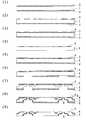
- FIG. 1is a diagram showing the steps of Example 1 of the lead frame manufacturing method according to the present invention, (1) is a diagram in which a resist layer is formed on a metal plate, (2) is a diagram in which a plating mask is formed, 3) is a diagram showing a plated layer, (4) is a diagram showing a plating mask removed, (5) is a diagram showing a resist layer formed on both sides of a metal plate on which plating is formed, and (6) is an etching mask. (7) is a diagram after etching, (8) is a diagram in which various etching processes using Sn, Zn or their metal are partially performed using an etching mask, and (9) is an etching mask. It is the figure which peeled.
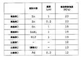
- FIG. 2is a table showing the evaluation results of the resin adhesion strength of the test pieces prepared in Examples and Comparative Examples.
- a photoresistis laminated on the front and back surfaces of the metal plate 1 to be a lead frame material, a photoresist layer 2 is provided, and a plating mask 3 on which a plating pattern is formed is placed thereon, and a photolithography step ( It is a process of drawing a plating pattern by transferring to a resist by exposure and development.
- a photoresistfor example, a dry film resist
- a glass mask on which a plating pattern is formedis transferred to the resist in a photolithography process (exposure and development), and a plating pattern is obtained.
- the plating mask 3 formed on both surfaces of the metal plate 1is peeled off with an aqueous sodium hydroxide solution (4), and then a photoresist is laminated on the metal plate 1 again (5) to form a lead frame pattern.
- the resulting glass maskis transferred to a resist by a photolithography process (6), and an excess metal portion is removed by etching using a ferric chloride solution to form a lead frame shape (7).
- Sn or Zn platingis performed by electrolytic plating (8). Thereby, Sn or Zn plating is performed with a thickness of 0.02 to 2.0 ⁇ m only on the etching melted surface (side surface of metal plate 1 and half-etched portion).
- the etching mask formed on both surfaces of the metal plate 1is peeled off with a sodium hydroxide aqueous solution, whereby the lead frame (9) according to the present invention is formed.
- the material of the metal plate 1is preferably a copper-based material, but is not limited thereto.
- a dry film resist(Asahi Kasei E-Materials Co., Ltd .: AQ-2058) was pasted on both sides to form a resist layer.
- a dry film resist(Asahi Kasei E-Materials Co., Ltd .: AQ-2058) was pasted on both sides to form a resist layer.
- exposure and developmentare performed to remove the resist in the portion where the plating is to be formed.
- a plating mask with the metal plate surface exposedwas formed.
- platingwas performed to form a plating on the exposed portion of the metal plate surface.
- three layers of platingwere formed by performing Ni plating with a set value of 1.0 ⁇ m, Pd plating with a set value of 0.02 ⁇ m, and Au plating with a set value of 0.007 ⁇ m in order from the metal plate side.
- the plating mask formed on both surfaces of the metal platewas peeled off with a 3% aqueous sodium hydroxide solution, and further washed with 3% sulfuric acid.
- a dry film resist(Asahi Kasei E-Materials Co., Ltd .: AQ-44096) is pasted on both surfaces of the metal plate on which the plating is formed to form a resist layer, and a glass mask in which the shape of the lead frame is formed is used. Both surfaces were exposed and developed to form an etching mask.
- Zn plating treatmentwas performed by an electrolytic plating method.
- This electric Zn plating bathis composed of NaOH 5 g / l, NaCN 35 g / l, and Zn (CN) 230 g / l, and is electroplated with a current density of 3 A / dm 2 to form a Zn plating with a film thickness of 1 ⁇ m. A layer was obtained.
- the residue of the Zn plating solution adhering to the Zn plating surfacewas removed by washing with hydrochloric acid by spraying, and then the etching mask was peeled off using an aqueous sodium hydroxide solution. Thereafter, acid treatment with sulfuric acid was performed to dry the surface, and the lead frame of Example 1 in which the product side surface and the etching-dissolved surface were partially plated with Zn was obtained.
- a lead frame of Example 2was obtained in the same manner as in Example 1 except that the thickness of the electro-Zn plating was changed to 0.2 ⁇ m.
- Example 3A lead frame of Example 3 was obtained in the same manner as in Example 1 except that Sn plating was applied instead of Zn.
- This electric Sn plating bathis composed of stannous sulfate 55 g / l, sulfuric acid 100 g / l, cresol sulfonic acid 60 g / l, gelatin 2 g / l, and ⁇ -naphthol 1 g / l, and the current density is 2 A / dm 2.
- the Sn plating layer having a film thickness of 1 ⁇ mwas obtained by electroplating with the electrode.
- Example 4The lead frame of Example 4 was formed in the same manner as in Example 1 except that Zn plating was applied to Jinny ST AF210 zinc-nickel alloy (Ni eutectoid rate of 12-15 wt%) manufactured by Atotech. Obtained.
- This ginny ST AF210 zinc-nickel alloy platingwas carried out in a basic solution of 213 g / l potassium chloride, 42 g / l zinc chloride and 121 g / l nickel chloride hexahydrate, 10 ml / l ginny ACAF211 as an additive, and ginny ACAF212.
- Example 5A lead frame of Example 5 was obtained in the same manner as in Example 1 except that NiP plating was applied instead of Ni.
- This electric NiP plating bathis composed of nickel sulfate 250 g / l, nickel chloride 50 g / l, boric acid 50 g / l, and Novoplate HS (Atotech Japan K.K.) 30 ml / l, with a current density of 2 A / dm. Then , electroplating with Sn was performed to obtain a 1 ⁇ m thick NiP plating layer.
- a lead frame of Comparative Example 1was obtained in the same manner as in Example 1 except that Zn plating was not applied after etching.
- a lead frame of Comparative Example 2was obtained in the same manner as in Example 1 except that copper roughening treatment was performed instead of Zn plating after etching.
- the copper roughening treatmentwas performed by spraying a roughening treatment liquid (MEC Co., Ltd .: CZ8100).
- This roughening treatment liquidwas prepared at a liquid temperature of 35 ° C., a specific gravity of 1.145, and a copper concentration of 35 g / L, and the roughening treatment was performed by spraying.
- the surface roughness of the roughened surfacewas SRa 0.2 to 0.4.
- a lead frame of Comparative Example 3was obtained in the same manner as in Example 1 except that Ag plating was applied instead of Zn plating.
- the Ag plating bathis composed of KCN 40 g / l, AgCN 35 g / l, K 2 CO 3 22 g / l, and electroplated with a current density of 3 A / dm 2 to obtain an Ag plating layer having a thickness of 0.2 ⁇ m. .
- the resin adhesion strengthwas evaluated by the following method. That is, four resins each having a diameter of 2 mm were formed on a metal base material under the conditions of a mold injection pressure of 100 kg / cm 2 and a mold temperature of 175 ° C. ⁇ 90 seconds, and were placed in an oven at 175 ° C. for 8 Curing treatment was performed over time to form four evaluation resin samples. Each of these evaluation resin samples was pushed from the side to measure the load when the resin was peeled off, and this value was divided by the adhesion area of the resin and converted into a load per unit area. The average of the four loads thus obtained was taken as the resin adhesion strength.
- the resin adhesion strengthis 23 MPa in the lead frame of Example 1.
- the lead frame of Example 2is 23 MPa
- the lead frame of Example 3is 19 MPa
- the lead frame of Example 4is 19 MPa
- the lead frame of Example 5is 19 MPa
- Comparative Example 1The lead frame was 10 MPa
- the lead frame of Comparative Example 2was 13 MPa
- the lead frame of Comparative Example 3was 12 MPa.
Landscapes
- Engineering & Computer Science (AREA)
- Physics & Mathematics (AREA)
- Condensed Matter Physics & Semiconductors (AREA)
- General Physics & Mathematics (AREA)
- Computer Hardware Design (AREA)
- Microelectronics & Electronic Packaging (AREA)
- Power Engineering (AREA)
- Manufacturing & Machinery (AREA)
- Geometry (AREA)
- Lead Frames For Integrated Circuits (AREA)
- Electroplating Methods And Accessories (AREA)
- Led Device Packages (AREA)
Abstract
Description
Translated fromJapanese本発明は、リードフレーム及びその製造方法に関し、特に樹脂との密着性に優れたリードフレームに関するものである。The present invention relates to a lead frame and a method for manufacturing the same, and particularly to a lead frame having excellent adhesion to a resin.
半導体パッケージは、金属製のリードフレームと封止用樹脂が主に使用されており、リードフレームは、銅合金が多用され、封止用樹脂は、エポキシ樹脂等が主流を占めている。The semiconductor package mainly uses a metal lead frame and a sealing resin. The lead frame is often made of a copper alloy, and the sealing resin is mainly an epoxy resin.
また、半導体パッケージの放熱用として、ヒートスプレッダと呼ばれる部品の材料は、銅板あるいは銅合金板が使用される場合があり、リードフレームとヒートスプレッダは封止用樹脂で固定されている。Also, a copper plate or a copper alloy plate may be used as a component material called a heat spreader for heat dissipation of the semiconductor package, and the lead frame and the heat spreader are fixed with a sealing resin.
このように、銅及び銅合金を用いた金属材料と樹脂とが接合している製品では、その密着性がしばしば問題になり、樹脂密着性を良好にする方策として、アンカー効果を得る為にリードフレーム及びヒートスプレッダの表面を粗化処理する方法が採用されている。As described above, in a product in which a metal material using copper and a copper alloy and a resin are bonded, the adhesion often becomes a problem. As a measure for improving the resin adhesion, a lead is used to obtain an anchor effect. A method of roughening the surface of the frame and the heat spreader is employed.
しかし、これらの方法の問題点としては、例えばQFN(Quad Flat Non-Lead)タイプの半導体パッケージでは、封止用樹脂の下面に接続端子が露出しており、金属材料の下面を粗化すると樹脂漏れを誘発する場合があり、その漏れた樹脂は、粗化によって剥離が難しくなるというジレンマを持っている。そのため、従来、部分的に粗化処理をする方法が提案されているが、これらの処理方法はコストアップにつながるという問題点をもっている。However, as a problem of these methods, for example, in a QFN (Quad Flat Non-Lead) type semiconductor package, the connection terminal is exposed on the lower surface of the sealing resin, and the resin material is roughened when the lower surface of the metal material is roughened. Leakage may be induced, and the leaked resin has the dilemma that it becomes difficult to peel off due to roughening. For this reason, methods of partially roughening have been proposed in the past, but these methods have the problem of increasing costs.
また、銅材の粗化処理は、銅材を高温加熱することで粗化面の銅酸化が進み酸化膜の剥離が起こりやすくなり、そして加熱前よりも樹脂密着性が低下することになるため、半導体パッケージとしての充分な信頼性を得るには至っていない。In addition, the copper material is roughened by heating the copper material at a high temperature, so that the copper oxidation of the roughened surface proceeds and the oxide film is easily peeled off, and the resin adhesion is lower than before the heating. However, sufficient reliability as a semiconductor package has not been obtained.
これらの粗化処理に代わる方策として、従来、特許文献1、特許文献2及び特許文献3に示す技術が開示されている。Conventionally, the techniques shown in
特許文献1には、半導体装置等の電子部品の放熱板において、放熱板と樹脂系接着剤との接着性を向上させる方法として、アミノシラン化合物を0.001%以上含む溶液中に、Ni又はNi合金メッキ付き金属板又は条材を浸漬し、接着剤にて樹脂と接着する部分の最表面にアミノシラン化合物皮膜を形成することが開示されている。In
特許文献2には、銅板を基板として、ニッケルめっき層を形成させ、その上にシランカップリング剤塗布層またはポリアクリル酸の皮膜を形成させて半導体用放熱板とし、これに半導体素子およびプリント基板を接着し、トランスファーモールド樹脂で半導体素子を封止し、接着樹脂との密着性に優れた半導体用放熱板を得ることが開示されている。In
特許文献3には、最表面にSi換算付着量で0.5mg/m2以上のシラン化合物被膜が形成され、その下層に厚さ1000~2000Åの酸化皮膜が形成された銅又は銅合金板又は条材であり、40℃~60℃のシランカップリング剤水溶液を、銅又は銅合金板又は条材の表面に塗布して該表面にシラン化合物被膜を形成した後、これを加熱処理し、前記シラン化合物皮膜の下層に前記銅又は銅合金板又は条状の酸化皮膜を厚さ1000~2000Åの厚さで形成し、樹脂との密着性に優れた銅合金板又は条材を得ることが開示されている。
これら従来の銅及び銅合金条材の化学的方法による表面処理では、樹脂との密着性を十分に向上させることは困難であり、依然としてリードフレームと樹脂との密着性を向上させる技術が求められている。In the conventional surface treatment of copper and copper alloy strips by a chemical method, it is difficult to sufficiently improve the adhesion between the resin and a technique for improving the adhesion between the lead frame and the resin is still required. ing.
ところで、樹脂との密着性を向上させるためのその他の方策として、素材となる銅材料表面をSnまたはその合金めっき、Znまたはその合金めっき処理する方法がある。
その場合、まず材料表面全体を、Sn,Zn又はそれら金属を含む各種の合金めっき処理をし、その後、めっき面をDFRによってマスキングした後に、エッチングを行うことにより所望のリードフレームを製造する。そして、結果的に、エッチング溶解されない材料面は、Sn,Zn又はそれらの金属を含む各種合金のめっき処理がなされ、エッチングされた溶解面については、Sn,Zn又はそれらの金属を含む各種合金のめっき処理されていないリードフレームが成形される。By the way, as another measure for improving the adhesiveness with the resin, there is a method of treating the surface of the copper material as the material with Sn or its alloy plating, or Zn or its alloy plating.
In this case, first, the entire surface of the material is subjected to various alloy plating treatments including Sn, Zn, or a metal thereof, and then a desired lead frame is manufactured by performing etching after masking the plated surface with DFR. As a result, the material surface that is not melted by etching is plated with various alloys containing Sn, Zn or their metals, and the etched molten surface is made of various alloys containing Sn, Zn or their metals. An unplated lead frame is formed.
或いは、エッチング、もしくはプレスにて成形されたリードフレームに、Sn,Zn又はそれらの金属を含む各種の合金めっき処理を施し、フレーム全体をSn,Zn又はそれらの金属を含む各種合金めっき処理する方法もある。この場合は、エッチング溶解面やプレスの切断面についても、全てSn,Zn又はそれらの金属を含む各種の合金めっき処理がされることになる。Alternatively, the lead frame formed by etching or pressing is subjected to various alloy plating treatments including Sn, Zn or their metals, and the entire frame is subjected to various alloy plating treatments including Sn, Zn or their metals. There is also. In this case, the etching dissolution surface and the cut surface of the press are all subjected to various alloy plating treatments including Sn, Zn or their metals.
このように、どちらの方法においても、元々の材料表面は、Sn,Zn又はそれらの金属を含む各種合金のめっきがなされるので、例えば材料表面に光沢が必要になるLED等の照明用途のリードフレームの場合は、材料表面をSn,Zn又はそれら金属を含む各種合金めっきをすることによって、材料表面に光の拡散が起きてしまうために、必要な光沢度を確保することができなくなる。Thus, in both methods, the original material surface is plated with Sn, Zn, or various alloys containing these metals, so that the material surface needs to be glossy, such as LEDs for lighting applications. In the case of a frame, light diffusion occurs on the material surface by plating the surface of the material with various kinds of alloys including Sn, Zn, or a metal thereof, so that the required glossiness cannot be ensured.
このためLED等の照明用途のリードフレームの場合は、樹脂の密着性を向上させたくとも、Sn,Zn又はそれらの金属を含む各種合金のめっき処理を行うことはできなかった。For this reason, in the case of lead frames for lighting applications such as LEDs, it was not possible to perform plating of Sn, Zn, or various alloys containing these metals, even if it was desired to improve the adhesion of the resin.
また、Sn,Zn又はそれらの金属を含む各種合金めっき処理によって、リードフレームの樹脂密着性は向上するが、Sn,Zn又はそれら金属を含む各種合金めっき処理していないリードフレームの材料表面と比べて、ワイヤーボンディング性が格段に低下してしまう。In addition, the resin adhesion of the lead frame is improved by various alloy plating treatments including Sn, Zn or their metals, but compared with the material surface of the lead frame which is not subjected to various alloy plating treatments including Sn, Zn or their metals. As a result, the wire bonding property is significantly reduced.
そのため、本来はSn,Zn又はそれらの金属を含む各種合金めっき処理を行った方が望ましいリードフレームであっても、Sn,Zn又はそれらの金属を含む各種合金めっき処理することの出来ないリードフレームも存在している。Therefore, even lead frames that are originally desirable to be plated with various alloys including Sn, Zn, or their metals, cannot be plated with various alloys including Sn, Zn, or their metals. Also exist.
上記実情に鑑み、本発明は、例えば素材面の光沢が必要なLED用途のリードフレームの場合において、Sn,Zn又はそれらの金属を含む各種合金めっき加工を行っても、表面光沢を損なうこと無く、且つ、ワイヤーボンディング性を低下させること無く、樹脂との密着性を向上させることができるリードフレームと、その製造方法を提供することを目的としている。In view of the above situation, the present invention, for example, in the case of a lead frame for an LED application that requires gloss on the surface of the material, does not impair the surface gloss even if various alloy plating processes including Sn, Zn or their metals are performed. And it aims at providing the lead frame which can improve adhesiveness with resin, and its manufacturing method, without reducing wire bonding property.
上記目的を達成するため、本発明のリードフレームは、リードフレームの側面及びハーフエッチング面にのみ、Sn,Zn又はそれらの金属を含むZnNi,SnBi,SnCu又はSnBの如き各種合金めっき層が形成されていることを特徴とする。In order to achieve the above object, in the lead frame of the present invention, various alloy plating layers such as ZnNi, SnBi, SnCu or SnB containing Sn, Zn or their metals are formed only on the side surface and half-etched surface of the lead frame. It is characterized by.
その場合、Sn,Zn又はそれらの金属を含む各種合金めっき層の厚さは、0.02~2.0μmであることを特徴とする。In that case, the thickness of the various alloy plating layers containing Sn, Zn or their metals is 0.02 to 2.0 μm.
また、本発明によれば、半導体素子またはLED素子が搭載される面となるリードフレームの表面には貴金属めっき層が形成され、それ以外の面には金属板が露出していることを特徴とする。According to the present invention, the noble metal plating layer is formed on the surface of the lead frame on which the semiconductor element or the LED element is mounted, and the metal plate is exposed on the other surface. To do.
その場合、貴金属めっき層は、Ni(又はNi合金)/Pd(又はPd合金)、Ni(又はNi合金)/Pd(又はPd合金)/Au(又はAu合金)、Ni(又はNi合金)/Pd(又はPd合金)/Au(又はAu合金)/Ag(又はAg合金)、Ni(又はNi合金)/Pd(又はPd合金)/Ag(又はAg合金)/Au(又はAu合金)、Cu(又はCu合金)/Ag(又はAg合金)の順に積層されていることを特徴とする。In that case, the noble metal plating layer is Ni (or Ni alloy) / Pd (or Pd alloy), Ni (or Ni alloy) / Pd (or Pd alloy) / Au (or Au alloy), Ni (or Ni alloy) / Pd (or Pd alloy) / Au (or Au alloy) / Ag (or Ag alloy), Ni (or Ni alloy) / Pd (or Pd alloy) / Ag (or Ag alloy) / Au (or Au alloy), Cu (Or Cu alloy) / Ag (or Ag alloy).
また、本発明に係るリードフレームの製造方法は、リードフレーム材料である金属板にレジストによるめっき用マスクを形成する工程と、めっき用マスクから露出している金属板部分にめっきを形成する工程と、レジストにより、形成されためっき部分を覆い、要求されるリードフレーム形状を得るためのエッチング用マスクを形成する工程と、エッチング加工により金属板に貫通加工およびハーフエッチング加工を施す工程と、エッチング加工をした貫通面およびハーフエッチング面にSn,Zn又はそれらの金属を含む各種合金めっきを施す工程と、を有することを特徴とする。The lead frame manufacturing method according to the present invention includes a step of forming a plating mask with a resist on a metal plate as a lead frame material, and a step of forming plating on a metal plate portion exposed from the plating mask. , A step of forming a mask for etching to cover the formed plated portion with a resist and obtaining a required lead frame shape, a step of performing a penetrating process and a half-etching process on a metal plate by an etching process, and an etching process And a step of applying various alloy platings containing Sn, Zn, or a metal thereof to the penetrating surface and the half-etched surface.
更に、本発明によれば、Sn,Znめっき又はSn,Znを含む各種合金めっきは、電気めっきが好ましいが、その他に、化学めっきや真空蒸着などの皮膜ができるめっきであれば如何なるめっきでもよく、また、本発明のリードフレームにおいては、めっき厚は、0.02~2.0μm程度が適当である。めっきの厚さが0.02μm以下の場合には効果が不十分であり、逆に、2.0μm以上の場合にはめっきの効果が増大しないからである。Furthermore, according to the present invention, Sn, Zn plating or various alloy plating containing Sn, Zn is preferably electroplating, but any other plating that can form a film such as chemical plating or vacuum deposition may be used. In the lead frame of the present invention, the plating thickness is suitably about 0.02 to 2.0 μm. This is because the effect is insufficient when the plating thickness is 0.02 μm or less, and conversely, when the thickness is 2.0 μm or more, the plating effect does not increase.
本発明によれば、エッチング溶解面(製品側面、及びハーフエッチング部分)のみに限定して、部分的にSn,Zn又はそれらの金属を含む各種合金によるめっき処理を行うようにしたから、リードフレームと樹脂との密着性を一段と向上させることができる。According to the present invention, the lead frame is formed by performing various plating treatments with Sn, Zn, or various alloys containing these metals, limited to only the etching dissolution surface (product side surface and half-etched portion). The adhesion between the resin and the resin can be further improved.
即ち、従来、表面光沢が必要なリードフレームにおいては、材料表面の全面にSn,Zn又はそれらの金属を含む各種合金めっきを行った場合は、Sn,Zn又はそれらの金属を含む各種合金をめっきしたことによる影響で、めっき後の表面光沢度を確保できないため、また、ワイヤーボンディング性が格段に低下するため、Sn,Zn又はそれらの金属を含む各種合金のめっき処理を行うことはできなかったが、本発明による部分的Sn,Zn又はそれらの金属を含む各種合金めっき法を適用することで、LED等の照明用途のリードフレームであっても、Sn,Zn又はそれら金属を含む各種合金めっきされるのはエッチング溶解面だけになるので、めっき後の光沢度に影響を及ぼすことなく、リードフレームとリフレクタ樹脂との密着性を向上させることが可能となる。That is, conventionally, in lead frames that require surface gloss, when various alloy platings containing Sn, Zn or their metals are performed on the entire surface of the material, plating of various alloys containing Sn, Zn or their metals is performed. As a result, the surface gloss after plating cannot be ensured, and the wire bonding property is remarkably lowered, so that it was not possible to perform the plating treatment of various alloys including Sn, Zn or their metals. However, by applying various alloy plating methods including partial Sn, Zn or their metals according to the present invention, various alloy plating including Sn, Zn or their metals can be used for lighting frames such as LEDs. Since only the melted surface is etched, the density of the lead frame and the reflector resin is not affected without affecting the glossiness after plating. It is possible to improve the resistance.
加えて、QFNタイプのリードフレームやその他IC用リードフレームにおいても、部分的なSn,Zn又はそれらの金属を含む各種合金めっきによる樹脂密着性の向上は可能であり、エッチング溶解面である製品側面へのSn,Zn又はそれらの金属を含む各種合金めっきはもちろんのこと、表面にハーフエッチング面を追加したり、既存のハーフエッチング面の面積を増やすことで、Sn,Zn又はそれらの金属を含む各種合金めっき面積は増加し樹脂密着性を向上させることができる。テープレスQFNについても、端子側面がSn,Zn又はそれら金属を含む各種合金めっき処理されるため、樹脂密着性を向上させることができる。In addition, even in QFN type lead frames and other IC lead frames, it is possible to improve resin adhesion by partial plating of Sn, Zn, or various alloys containing these metals, and the product side which is an etching dissolution surface In addition to various alloy plating containing Sn, Zn or their metals on the surface, adding a half-etched surface to the surface or increasing the area of the existing half-etched surface includes Sn, Zn or their metals Various alloy plating areas can be increased and resin adhesion can be improved. Also for tapeless QFN, since the terminal side surface is subjected to various alloy plating treatments including Sn, Zn or these metals, the resin adhesion can be improved.
また、従来、銅面の粗化処理等によって樹脂密着性の向上を図った場合には、経時変化やアッセンブリによる加熱処理等により、粗化面の銅酸化が進み酸化膜剥離が起こりやすくなり、樹脂密着性が劣化するケースが少なくないが、本発明方法による場合は、経時変化や加熱処理等により形成されるSn,Zn又はそれらの金属を含む各種合金酸化膜が樹脂との密着性を向上させ、また、これらの酸化膜は加熱等で樹脂密着性が劣化することはない。Also, conventionally, when resin adhesion is improved by roughening the copper surface, etc., the copper oxidation of the roughened surface proceeds due to changes over time or heat treatment by assembly, etc., and oxide film peeling tends to occur. There are many cases in which the resin adhesion deteriorates, but in the case of the method of the present invention, Sn, Zn or various alloy oxide films containing these metals formed by aging, heat treatment, etc. improve the adhesion to the resin. In addition, the resin adhesiveness of these oxide films is not deteriorated by heating or the like.
更に、部分的なSn,Zn又はそれら金属を含む各種合金めっきを行うためには、Sn,Zn又はそれらの金属を含む各種合金めっき用のマスクが必要になるが、本発明では、エッチング用のマスクをそのままSn,Zn又はそれらの金属を含む各種合金めっき用のマスクとして使用するので、エッチング加工からSn,Zn又はそれらの金属を含む各種合金めっき処理を同一装置により連続的に行うことが可能となり、部分的にSn,Zn又はそれら金属を含む各種合金めっき処理をするリードフレームの場合でも低コストで生産することが可能となる。Furthermore, in order to perform various alloy platings containing partial Sn, Zn or their metals, a mask for various alloy platings containing Sn, Zn or their metals is required. Since the mask is used as it is as a mask for plating various alloys containing Sn, Zn or their metals, it is possible to continuously perform various alloy plating treatments containing Sn, Zn or their metals from the etching process using the same apparatus. Therefore, even in the case of a lead frame that is subjected to various alloy plating processes including Sn, Zn, or these metals partially, it can be produced at low cost.
又、本発明方法により、リードフレームの形状やデザインにおいて、その用途(LED用、IC用)にかかわらず、部分的にハーフエッチング部分を追加したり、既存のハーフエッチング面積を増やしたりすることによって、Sn,Zn又はそれら金属を含む各種合金めっき処理面積は増大し、更に樹脂密着性を向上させることが可能となる。In addition, according to the method of the present invention, by partially adding a half-etched part or increasing the existing half-etched area in the shape and design of the lead frame regardless of its use (for LED, for IC) , Sn, Zn, or various alloy plating treatment areas containing these metals can be increased, and the resin adhesion can be further improved.
以下、図1を参照して本発明に係るリードフレームの製造方法を説明する。
最初の工程は、リードフレーム素材となるべき金属板1の表裏面にフォトレジストをラミネートしてフォトレジスト層2を設け、その上にめっきパターンの形成されためっきマスク3を被せ、フォトリソグラフィ工程(露光及び現像)でレジストに転写し、めっきパターンを描画する工程である。
その工程は、金属板1上にフォトレジスト(例えば、ドライフィルムレジスト)をラミネートし(1)、めっきパターンの形成されたガラスマスクをフォトリソグラフィ工程(露光及び現像)でレジストに転写し、めっきパターンを金属板1上に描画し(2)、次に、電解めっき法によってNi/Pd/AuあるいはAgめっき4を施し、Ni/Pd/AuあるいはAg被膜を形成する(3)。Hereinafter, a lead frame manufacturing method according to the present invention will be described with reference to FIG.
In the first step, a photoresist is laminated on the front and back surfaces of the
In this process, a photoresist (for example, a dry film resist) is laminated on the metal plate 1 (1), a glass mask on which a plating pattern is formed is transferred to the resist in a photolithography process (exposure and development), and a plating pattern is obtained. Is drawn on the metal plate 1 (2), and then Ni / Pd / Au or Ag plating 4 is applied by electrolytic plating to form a Ni / Pd / Au or Ag coating (3).
次に、金属板1の両面に形成されているめっきマスク3を水酸化ナトリウム水溶液により剥離し(4)、その後再度、金属板1上にフォトレジストをラミネートし(5)、リードフレームパターンの形成されたガラスマスクをフォトリソグラフィ工程でレジストに転写し(6)、塩化第二鉄液を用いたエッチングで余分な金属部分を除去してリードフレーム形状を形成する(7)。Next, the
次に、電解めっき法によって、SnまたはZnめっき処理を行う(8)。それにより、エッチング溶解面(金属板1の側面、及びハーフエッチング部分)のみに限定して、SnまたはZnめっきが0.02~2.0μmの厚みで施される。Next, Sn or Zn plating is performed by electrolytic plating (8). Thereby, Sn or Zn plating is performed with a thickness of 0.02 to 2.0 μm only on the etching melted surface (side surface of
最後に、金属板1の両面に形成されているエッチングマスクを水酸化ナトリウム水溶液により剥離することにより、本発明によるリードフレーム(9)が形成される。Finally, the etching mask formed on both surfaces of the
かくして、本発明によれば、封止樹脂との密着性が向上し、さらに、ワイヤーボンディング性も従来と同等のリードフレームを提供することができる。なお、本発明では、金属板1の材料としては、銅系の材料が好適であるが、これに限定されるものではない。Thus, according to the present invention, it is possible to provide a lead frame having improved adhesion to the sealing resin and having the same wire bonding property as that of the prior art. In the present invention, the material of the
金属板1として厚さが0.150mmの銅材を用いて、両面にドライフィルムレジスト(旭化成イーマテリアルズ株式会社:AQ-2058)を貼り付け、レジスト層を形成した。次に、めっきを形成するためのパターンが形成された上面側用と裏面側用のガラスマスクを用いて、露光及び現像を行うことで、めっきを形成する部分のレジストを除去し、部分的に金属板表面を露出させためっきマスクを形成した。Using a copper material having a thickness of 0.150 mm as the
次に、めっき加工を行なって金属板表面の露出部分にめっきを形成した。本実施例では、金属板側から順に、設定値1.0μmのNiめっき、設定値0.02μmのPdめっき、設定値0.007μmのAuめっきを施して、3層のめっきを形成した。Next, plating was performed to form a plating on the exposed portion of the metal plate surface. In this example, three layers of plating were formed by performing Ni plating with a set value of 1.0 μm, Pd plating with a set value of 0.02 μm, and Au plating with a set value of 0.007 μm in order from the metal plate side.
次に、金属板の両面に形成されているめっきマスクを3%の水酸化ナトリウム水溶液により剥離し、更に3%の硫酸による洗浄処理も行なった。Next, the plating mask formed on both surfaces of the metal plate was peeled off with a 3% aqueous sodium hydroxide solution, and further washed with 3% sulfuric acid.
次に、めっきが形成された金属板の両面にドライフィルムレジスト(旭化成イーマテリアルズ株式会社:AQ-44096)を貼り付けてレジスト層を形成し、リードフレームの形状が形成されたガラスマスクを用いて両面を露光し現像を行ってエッチングマスクを形成した。Next, a dry film resist (Asahi Kasei E-Materials Co., Ltd .: AQ-44096) is pasted on both surfaces of the metal plate on which the plating is formed to form a resist layer, and a glass mask in which the shape of the lead frame is formed is used. Both surfaces were exposed and developed to form an etching mask.
次に、塩化第二鉄液を用いてスプレーエッチング加工を行い、リードフレームの形成を行った。 エッチング加工は、液温70℃、比重1.47の塩化第二鉄液を用い、搖動するスプレーノズルによって0.3MPaの設定圧力で噴射させ、約160秒間の処理を行なった。Next, spray etching processing was performed using ferric chloride solution to form a lead frame. Etching was carried out using a ferric chloride solution having a liquid temperature of 70 ° C. and a specific gravity of 1.47, sprayed at a set pressure of 0.3 MPa by a peristaltic spray nozzle, and was processed for about 160 seconds.
次に、エッチング溶解面に付着した銅結晶をスプレー噴射による硫酸洗浄にて除去した後、電解めっき法によって、Znめっき処理を行った。この電気Znめっき浴は、NaOH 5g/l、NaCN 35g/l、および、Zn(CN)230g/lから構成され、電流密度を3A/dm2で電気Znめっきして、膜厚1μmのZnめっき層を得た。Next, after removing the copper crystal adhering to the etching dissolution surface by sulfuric acid washing by spraying, Zn plating treatment was performed by an electrolytic plating method. This electric Zn plating bath is composed of NaOH 5 g / l, NaCN 35 g / l, and Zn (CN) 230 g / l, and is electroplated with a current density of 3 A / dm2 to form a Zn plating with a film thickness of 1 μm. A layer was obtained.
次に、Znめっき面に付着したZnめっき処理液の残渣物をスプレー噴射による塩酸洗浄にて除去し、その後、水酸化ナトリウム水溶液を用いてエッチングマスクを剥離した。その後、硫酸による酸処理を行い表面を乾燥させ、製品側面およびエッチング溶解面が部分的にZnめっきされた、実施例1のリードフレームを得た。Next, the residue of the Zn plating solution adhering to the Zn plating surface was removed by washing with hydrochloric acid by spraying, and then the etching mask was peeled off using an aqueous sodium hydroxide solution. Thereafter, acid treatment with sulfuric acid was performed to dry the surface, and the lead frame of Example 1 in which the product side surface and the etching-dissolved surface were partially plated with Zn was obtained.
電気Znめっきの膜厚を0.2μmにしたことを除いて、実施例1で行ったのと同様の方法で実施例2のリードフレームを得た。A lead frame of Example 2 was obtained in the same manner as in Example 1 except that the thickness of the electro-Zn plating was changed to 0.2 μm.
Znの代わりにSnめっきを適用することを除いて、実施例1で行ったのと同様の方法で実施例3のリードフレームを得た。この電気Snめっき浴は、硫酸第一スズ55g/l、硫酸100g/l、クレゾールスルホン酸60g/l、ゼラチン2g/l、および、βナフトール1g/lから構成され、電流密度を2A/dm2で電気Snめっきして、膜厚1μmのSnめっき層を得た。A lead frame of Example 3 was obtained in the same manner as in Example 1 except that Sn plating was applied instead of Zn. This electric Sn plating bath is composed of stannous sulfate 55 g / l, sulfuric acid 100 g / l, cresol sulfonic acid 60 g / l, gelatin 2 g / l, and β-naphthol 1 g / l, and the current density is 2 A / dm2. The Sn plating layer having a film thickness of 1 μm was obtained by electroplating with the electrode.
ZnめっきをAtotech社製ジンニーST AF210亜鉛ニッケル合金(Ni共析率12-15wt%)めっきを適用することを除いて、実施例1で行ったのと同様の方法で実施例4のリードフレームを得た。このジンニーST AF210亜鉛ニッケル合金めっきは、塩化カリウム213g/l、塩化亜鉛42g/l、および、塩化ニッケル6水和物121g/lの基本液に、添加剤としてジンニーACAF211を10ml/l、ジンニーACAF212を20ml/l、ジンニーACAF214を20ml/l、ジンニーACAF216を70ml/lを添加しためっき液から構成され、電流密度を2A/dm2で電気めっきして、膜厚1μmのZnNi合金めっき層を得た。The lead frame of Example 4 was formed in the same manner as in Example 1 except that Zn plating was applied to Jinny ST AF210 zinc-nickel alloy (Ni eutectoid rate of 12-15 wt%) manufactured by Atotech. Obtained. This ginny ST AF210 zinc-nickel alloy plating was carried out in a basic solution of 213 g / l potassium chloride, 42 g / l zinc chloride and 121 g / l nickel chloride hexahydrate, 10 ml / l ginny ACAF211 as an additive, and ginny ACAF212. Is formed from a plating solution to which 20 ml / l of ginny ACAF214 and 20 ml / l of ginny ACAF214 are added, and electroplating at a current density of 2 A / dm2 to obtain a ZnNi alloy plating layer having a thickness of 1 μm. It was.
Niの代わりにNiPめっきを適用することを除いて、実施例1で行ったのと同様の方法で実施例5のリードフレームを得た。この電気NiPめっき浴は、硫酸ニッケル250g/l、塩化ニッケル50g/l、ホウ酸50g/l、および、ノボプレートHS(アトテックジャパン(株))30ml/lから構成され、電流密度を2A/dm2で電気Snめっきして、膜厚1μmのNiPめっき層を得た。A lead frame of Example 5 was obtained in the same manner as in Example 1 except that NiP plating was applied instead of Ni. This electric NiP plating bath is composed of nickel sulfate 250 g / l, nickel chloride 50 g / l, boric acid 50 g / l, and Novoplate HS (Atotech Japan K.K.) 30 ml / l, with a current density of 2 A / dm.Then , electroplating with Sn was performed to obtain a 1 μm thick NiP plating layer.
以上、実施例を説明したが、本発明はこれらの実施例によって限定されるものではない。Although the embodiments have been described above, the present invention is not limited to these embodiments.
エッチング後にZnめっきを適用しなかったことを除いて、実施例1で行ったのと同様の方法で比較例1のリードフレームを得た。A lead frame of Comparative Example 1 was obtained in the same manner as in Example 1 except that Zn plating was not applied after etching.
エッチング後にZnめっきの代わりに、銅粗化処理を行なったことを除いて、実施例1で行ったのと同様の方法で比較例2のリードフレームを得た。銅粗化処理は粗化処理液(メック株式会社:CZ8100)をスプレー噴射することにより行った。この粗化処理液は液温35℃、比重1.145、銅濃度35g/Lに調液し、スプレー噴射にて粗化処理を行った。粗化面の表面粗さはSRa0.2~0.4となった。A lead frame of Comparative Example 2 was obtained in the same manner as in Example 1 except that copper roughening treatment was performed instead of Zn plating after etching. The copper roughening treatment was performed by spraying a roughening treatment liquid (MEC Co., Ltd .: CZ8100). This roughening treatment liquid was prepared at a liquid temperature of 35 ° C., a specific gravity of 1.145, and a copper concentration of 35 g / L, and the roughening treatment was performed by spraying. The surface roughness of the roughened surface was SRa 0.2 to 0.4.
Znめっきの代わりにAgめっきを適用することを除いて、実施例1で行ったのと同様の方法で比較例3のリードフレームを得た。Agめっき浴は、KCN 40g/l、AgCN 35g/l、K2CO3 22g/lから構成され、電流密度3A/dm2で電気Agめっきして膜厚0.2μmのAgめっき層を得た。A lead frame of Comparative Example 3 was obtained in the same manner as in Example 1 except that Ag plating was applied instead of Zn plating. The Ag plating bath is composed of KCN 40 g / l, AgCN 35 g / l, K2 CO3 22 g / l, and electroplated with a current density of 3 A / dm2 to obtain an Ag plating layer having a thickness of 0.2 μm. .
このようにして形成されたリードフレームから樹脂密着性評価試験のための試験片を切り出し、
これら試験片の樹脂密着性を判断するために、下記の方法により樹脂密着強度を評価した。即ち、金属製基材の上に、金型注入圧力100kg/cm2、金型温度175℃×90秒の条件で直径2mmの大きさの樹脂を4つ形成し、175℃のオーブン中で8時間に亘って硬化処理して、4点の評価用樹脂見本を形成した。これら評価用樹脂見本をそれぞれ真横から押して樹脂が剥離したときの荷重を測定し、この値を樹脂の接着面積で割って単位面積あたりの荷重に換算した。このようにして得られた4点の荷重の平均をとって樹脂密着強度とした。Cut out a test piece for the resin adhesion evaluation test from the lead frame formed in this way,
In order to judge the resin adhesion of these test pieces, the resin adhesion strength was evaluated by the following method. That is, four resins each having a diameter of 2 mm were formed on a metal base material under the conditions of a mold injection pressure of 100 kg / cm2 and a mold temperature of 175 ° C. × 90 seconds, and were placed in an oven at 175 ° C. for 8 Curing treatment was performed over time to form four evaluation resin samples. Each of these evaluation resin samples was pushed from the side to measure the load when the resin was peeled off, and this value was divided by the adhesion area of the resin and converted into a load per unit area. The average of the four loads thus obtained was taken as the resin adhesion strength.
上記のようにして、実施例および比較例で作製したリードフレームのそれぞれに対して樹脂密着強度を評価した結果、図2に示したように、樹脂密着強度は、実施例1のリードフレームでは23MPaであり、実施例2のリードフレームでも23MPaであり、実施例3のリードフレームでは19MPaであり、実施例4のリードフレームでは19MPaであり、実施例5のリードフレームでは19MPaであり、比較例1のリードフレームでは10MPaであり、比較例2のリードフレームでは13MPaであり、比較例3のリードフレームでは12MPaであった。As described above, as a result of evaluating the resin adhesion strength for each of the lead frames produced in the example and the comparative example, as shown in FIG. 2, the resin adhesion strength is 23 MPa in the lead frame of Example 1. The lead frame of Example 2 is 23 MPa, the lead frame of Example 3 is 19 MPa, the lead frame of Example 4 is 19 MPa, the lead frame of Example 5 is 19 MPa, and Comparative Example 1 The lead frame was 10 MPa, the lead frame of Comparative Example 2 was 13 MPa, and the lead frame of Comparative Example 3 was 12 MPa.
これらの結果から、製品側面およびハーフエッチ面のみを薄くSnまたはZnめっきした場合には、SnまたはZnめっきしない場合の2倍程度の密着強度が得られることが確認された。また、Znのめっき厚は0.2~1μmの範囲では密着強度に変化はなく十分に高いレベルにあった。また、SnまたはZnめっきの代わりに、銅粗化処理を行った場合や、Agめっきを行った場合には、SnまたはZnめっきのような高い密着強度が得られないことがわかった。
一方、ZnNiめっきやNiPめっきを行った場合にも、SnまたはZnめっきと同等レベルの高い密着強度が得られることがわかった。
符号の説明 From these results, it was confirmed that when only the product side surface and the half-etched surface were thinly plated with Sn or Zn, the adhesion strength about twice that without Sn or Zn plating was obtained. The Zn plating thickness was in a sufficiently high level with no change in adhesion strength in the range of 0.2 to 1 μm. Further, it was found that high adhesion strength like Sn or Zn plating could not be obtained when copper roughening treatment was performed instead of Sn or Zn plating, or when Ag plating was performed.
On the other hand, it was found that high adhesion strength equivalent to that of Sn or Zn plating can be obtained even when ZnNi plating or NiP plating is performed.
Explanation of symbols
1・・・金属板
2・・・レジスト層
3・・・めっきマスク
4・・・めっき
5・・・エッチングマスク
6・・・SnまたはZnめっき処理面DESCRIPTION OF
Claims (6)
Translated fromJapanese前記めっき用マスクから露出している前記金属板にめっきを形成する工程と、
レジストにより、形成された前記めっき部分を覆い、要求されるリードフレーム形状を得るためのエッチング用マスクを形成する工程と、
エッチングにより金属板に貫通加工およびハーフエッチング加工を施す工程と、
エッチング加工をした貫通面およびハーフエッチング面にSn,Znめっき又はそれら金属を含む各種合金めっきを施す工程と、
を有することを特徴とするリードフレームの製造方法。Forming a resist plating mask on the metal plate of the lead frame material;
Forming a plating on the metal plate exposed from the plating mask;
A step of forming an etching mask for covering the formed plating portion with a resist and obtaining a required lead frame shape;
A process of penetrating and half-etching a metal plate by etching;
A process of performing Sn, Zn plating or various alloy platings containing these metals on the etched through surface and half-etched surface;
A method for manufacturing a lead frame, comprising:
Priority Applications (3)
| Application Number | Priority Date | Filing Date | Title |
|---|---|---|---|
| CN201580045865.2ACN106575646B (en) | 2014-08-26 | 2015-07-30 | Lead frame and method for manufacturing the same |
| US15/504,404US9735096B1 (en) | 2014-08-26 | 2015-07-30 | Lead frame and method for manufacturing the same |
| KR1020177005014AKR102333434B1 (en) | 2014-08-26 | 2015-07-30 | Lead frame and production method therefor |
Applications Claiming Priority (2)
| Application Number | Priority Date | Filing Date | Title |
|---|---|---|---|
| JP2014-171974 | 2014-08-26 | ||
| JP2014171974AJP6493952B2 (en) | 2014-08-26 | 2014-08-26 | Lead frame and manufacturing method thereof |
Publications (1)
| Publication Number | Publication Date |
|---|---|
| WO2016031482A1true WO2016031482A1 (en) | 2016-03-03 |
Family
ID=55399383
Family Applications (1)
| Application Number | Title | Priority Date | Filing Date |
|---|---|---|---|
| PCT/JP2015/071644WO2016031482A1 (en) | 2014-08-26 | 2015-07-30 | Lead frame and production method therefor |
Country Status (6)
| Country | Link |
|---|---|
| US (1) | US9735096B1 (en) |
| JP (1) | JP6493952B2 (en) |
| KR (1) | KR102333434B1 (en) |
| CN (1) | CN106575646B (en) |
| TW (1) | TWI653723B (en) |
| WO (1) | WO2016031482A1 (en) |
Cited By (4)
| Publication number | Priority date | Publication date | Assignee | Title |
|---|---|---|---|---|
| CN106521583A (en)* | 2016-11-22 | 2017-03-22 | 宁波康强电子股份有限公司 | Electroplating method of lead frame |
| JP2017168689A (en)* | 2016-03-16 | 2017-09-21 | Shマテリアル株式会社 | LED package, multi-row type LED lead frame and manufacturing method thereof |
| JP2017168691A (en)* | 2016-03-16 | 2017-09-21 | Shマテリアル株式会社 | Led package, and lead frame for multiple row type led and method for manufacturing the same |
| TWI733941B (en)* | 2016-11-15 | 2021-07-21 | 日商新光電氣工業股份有限公司 | Lead frame and a method of manufacturing a lead frame and a method of manufacturing an electronic component device |
Families Citing this family (6)
| Publication number | Priority date | Publication date | Assignee | Title |
|---|---|---|---|---|
| JP6551267B2 (en) | 2016-03-10 | 2019-07-31 | 信越化学工業株式会社 | Cement mortar composition |
| DE102017119344A1 (en)* | 2017-08-24 | 2019-02-28 | Osram Opto Semiconductors Gmbh | Carrier and component with buffer layer and method for producing a component |
| JP7256382B2 (en)* | 2019-04-26 | 2023-04-12 | 日亜化学工業株式会社 | Method for manufacturing light emitting device |
| CN111787706A (en)* | 2020-07-16 | 2020-10-16 | 田秋国 | Processing method of substrate-free circuit board |
| CN112151489B (en)* | 2020-09-01 | 2023-06-06 | 通富微电科技(南通)有限公司 | Lead frame, method for forming lead frame, and lead frame package |
| JP7343084B2 (en) | 2021-09-03 | 2023-09-12 | 大日本印刷株式会社 | Lead frame and its manufacturing method |
Citations (2)
| Publication number | Priority date | Publication date | Assignee | Title |
|---|---|---|---|---|
| JPH07503103A (en)* | 1992-01-17 | 1995-03-30 | オリン コーポレイション | package |
| JP2013153032A (en)* | 2012-01-25 | 2013-08-08 | Panasonic Corp | Manufacturing method of led package |
Family Cites Families (16)
| Publication number | Priority date | Publication date | Assignee | Title |
|---|---|---|---|---|
| JP2000031366A (en)* | 1998-07-14 | 2000-01-28 | Dainippon Printing Co Ltd | Resin-sealed semiconductor device, circuit member used for the same, and method of manufacturing the same |
| JP2000133763A (en)* | 1998-10-26 | 2000-05-12 | Dainippon Printing Co Ltd | Circuit member for resin-sealed semiconductor device and method of manufacturing the same |
| JP3765709B2 (en) | 2000-06-01 | 2006-04-12 | 株式会社神戸製鋼所 | Manufacturing method of plated metal plates and strips for heat sinks of electronic parts |
| JP3895570B2 (en)* | 2000-12-28 | 2007-03-22 | 株式会社ルネサステクノロジ | Semiconductor device |
| US6661083B2 (en)* | 2001-02-27 | 2003-12-09 | Chippac, Inc | Plastic semiconductor package |
| JP2002270740A (en) | 2001-03-09 | 2002-09-20 | Toyo Kohan Co Ltd | Heat dissipating plate for semiconductor and semiconductor device using the same |
| JP2005226096A (en) | 2004-02-10 | 2005-08-25 | Kobe Steel Ltd | Copper or copper alloy sheet/bar stock for electronic component, and production method therefor |
| CN100483707C (en)* | 2004-05-27 | 2009-04-29 | 新光电气工业株式会社 | Lead frame for semiconductor device |
| JP5428667B2 (en)* | 2009-09-07 | 2014-02-26 | 日立化成株式会社 | Manufacturing method of semiconductor chip mounting substrate |
| TW201250964A (en)* | 2011-01-27 | 2012-12-16 | Dainippon Printing Co Ltd | Resin-attached lead frame, method for manufacturing same, and lead frame |
| JP5813335B2 (en)* | 2011-02-08 | 2015-11-17 | 新光電気工業株式会社 | Lead frame, semiconductor device, lead frame manufacturing method, and semiconductor device manufacturing method |
| CN102222658B (en)* | 2011-06-30 | 2013-08-14 | 天水华天科技股份有限公司 | Multi-circle arranged IC (integrated circuit) chip packaging member and producing method thereof |
| CN202549829U (en)* | 2012-04-06 | 2012-11-21 | 天水华天科技股份有限公司 | Pin-free package with four flat sides |
| JP6057285B2 (en)* | 2012-10-26 | 2017-01-11 | Shマテリアル株式会社 | Semiconductor device mounting substrate |
| CN203103285U (en)* | 2012-12-15 | 2013-07-31 | 华天科技(西安)有限公司 | A High Density Etched Leadframe FCAAQFN Package |
| JP2014146827A (en)* | 2014-03-27 | 2014-08-14 | Dainippon Printing Co Ltd | Surface lamination structure of circuit member |
- 2014
- 2014-08-26JPJP2014171974Apatent/JP6493952B2/enactiveActive
- 2015
- 2015-07-30WOPCT/JP2015/071644patent/WO2016031482A1/enactiveApplication Filing
- 2015-07-30USUS15/504,404patent/US9735096B1/enactiveActive
- 2015-07-30KRKR1020177005014Apatent/KR102333434B1/enactiveActive
- 2015-07-30CNCN201580045865.2Apatent/CN106575646B/enactiveActive
- 2015-08-13TWTW104126382Apatent/TWI653723B/enactive
Patent Citations (2)
| Publication number | Priority date | Publication date | Assignee | Title |
|---|---|---|---|---|
| JPH07503103A (en)* | 1992-01-17 | 1995-03-30 | オリン コーポレイション | package |
| JP2013153032A (en)* | 2012-01-25 | 2013-08-08 | Panasonic Corp | Manufacturing method of led package |
Cited By (4)
| Publication number | Priority date | Publication date | Assignee | Title |
|---|---|---|---|---|
| JP2017168689A (en)* | 2016-03-16 | 2017-09-21 | Shマテリアル株式会社 | LED package, multi-row type LED lead frame and manufacturing method thereof |
| JP2017168691A (en)* | 2016-03-16 | 2017-09-21 | Shマテリアル株式会社 | Led package, and lead frame for multiple row type led and method for manufacturing the same |
| TWI733941B (en)* | 2016-11-15 | 2021-07-21 | 日商新光電氣工業股份有限公司 | Lead frame and a method of manufacturing a lead frame and a method of manufacturing an electronic component device |
| CN106521583A (en)* | 2016-11-22 | 2017-03-22 | 宁波康强电子股份有限公司 | Electroplating method of lead frame |
Also Published As
| Publication number | Publication date |
|---|---|
| CN106575646A (en) | 2017-04-19 |
| KR102333434B1 (en) | 2021-11-30 |
| CN106575646B (en) | 2021-01-05 |
| JP6493952B2 (en) | 2019-04-03 |
| JP2016046488A (en) | 2016-04-04 |
| TW201622090A (en) | 2016-06-16 |
| US9735096B1 (en) | 2017-08-15 |
| KR20170048351A (en) | 2017-05-08 |
| TWI653723B (en) | 2019-03-11 |
| US20170236775A1 (en) | 2017-08-17 |
Similar Documents
| Publication | Publication Date | Title |
|---|---|---|
| JP6493952B2 (en) | Lead frame and manufacturing method thereof | |
| US7190057B2 (en) | Packaging component and semiconductor package | |
| JP2010199166A (en) | Lead frame for optical semiconductor apparatus, and method of manufacturing the same | |
| JP2002100718A (en) | Lead frame for semiconductor device, method of manufacturing the same, and semiconductor device using the same | |
| TW201022484A (en) | Method for improving the adhesion between silver surfaces and resin materials | |
| CN209626210U (en) | Semiconductor devices and integrated circuit systems | |
| JP4698708B2 (en) | Package parts and semiconductor packages | |
| JP2006093559A (en) | Lead frame and its manufacturing method | |
| JP5264939B2 (en) | Package parts and semiconductor packages | |
| JPH09148508A (en) | Lead frame for semiconductor device and plastic molded type semiconductor device using the same | |
| US20090196999A1 (en) | Adhesion promotion | |
| TWI660068B (en) | Lead-frame structure, lead-frame, surface mount electronic device and methods of producing same | |
| TW201803065A (en) | Lead frame material and method for producing same | |
| KR100947921B1 (en) | Highly Flexible Au Surface Treatment Plating of Flexible Printed Circuit Boards | |
| JPH11121673A (en) | Lead frame | |
| JP5387374B2 (en) | Lead frame manufacturing method | |
| JP2009099871A (en) | Lead frame, manufacturing method thereof, resin-encapsulated semiconductor device, and manufacturing method thereof | |
| JP6805217B2 (en) | Conductive materials, molded products and electronic components | |
| US11990394B2 (en) | Semiconductor package and a method for manufacturing of a semiconductor package | |
| JP2000340733A (en) | Pre-processed lead frame for semiconductor device and manufacture thereof | |
| JP4628263B2 (en) | Package component, manufacturing method thereof, and semiconductor package | |
| KR101375192B1 (en) | Method for preventing epoxy bleed out of lead frame | |
| JPH03237750A (en) | Lead frame for semiconductor integrated circuit | |
| JP2017117985A (en) | Method for manufacturing lead frame | |
| JPH04174546A (en) | Manufacture of semiconductor lead frame |
Legal Events
| Date | Code | Title | Description |
|---|---|---|---|
| 121 | Ep: the epo has been informed by wipo that ep was designated in this application | Ref document number:15836912 Country of ref document:EP Kind code of ref document:A1 | |
| WWE | Wipo information: entry into national phase | Ref document number:15504404 Country of ref document:US | |
| ENP | Entry into the national phase | Ref document number:20177005014 Country of ref document:KR Kind code of ref document:A | |
| NENP | Non-entry into the national phase | Ref country code:DE | |
| 122 | Ep: pct application non-entry in european phase | Ref document number:15836912 Country of ref document:EP Kind code of ref document:A1 |