WO2016012546A1 - Energy store - Google Patents
Energy storeDownload PDFInfo
- Publication number
- WO2016012546A1 WO2016012546A1PCT/EP2015/066892EP2015066892WWO2016012546A1WO 2016012546 A1WO2016012546 A1WO 2016012546A1EP 2015066892 WEP2015066892 WEP 2015066892WWO 2016012546 A1WO2016012546 A1WO 2016012546A1
- Authority
- WO
- WIPO (PCT)
- Prior art keywords
- management system
- battery management
- energy store
- bms
- display device
- Prior art date
Links
- 238000004146energy storageMethods0.000claimsdescription21
- 239000008186active pharmaceutical agentSubstances0.000claimsdescription16
- 238000004891communicationMethods0.000description8
- 238000010586diagramMethods0.000description3
- 238000010304firingMethods0.000description2
- 239000003086colorantSubstances0.000description1
- 238000011161developmentMethods0.000description1
- 230000018109developmental processEffects0.000description1
- 230000000694effectsEffects0.000description1
- 210000003205muscleAnatomy0.000description1
- 238000000926separation methodMethods0.000description1
Images

Classifications
- H—ELECTRICITY
- H01—ELECTRIC ELEMENTS
- H01M—PROCESSES OR MEANS, e.g. BATTERIES, FOR THE DIRECT CONVERSION OF CHEMICAL ENERGY INTO ELECTRICAL ENERGY
- H01M10/00—Secondary cells; Manufacture thereof
- H01M10/42—Methods or arrangements for servicing or maintenance of secondary cells or secondary half-cells
- H01M10/425—Structural combination with electronic components, e.g. electronic circuits integrated to the outside of the casing
- H01M10/4257—Smart batteries, e.g. electronic circuits inside the housing of the cells or batteries
- H—ELECTRICITY
- H01—ELECTRIC ELEMENTS
- H01M—PROCESSES OR MEANS, e.g. BATTERIES, FOR THE DIRECT CONVERSION OF CHEMICAL ENERGY INTO ELECTRICAL ENERGY
- H01M10/00—Secondary cells; Manufacture thereof
- H01M10/42—Methods or arrangements for servicing or maintenance of secondary cells or secondary half-cells
- H01M10/48—Accumulators combined with arrangements for measuring, testing or indicating the condition of cells, e.g. the level or density of the electrolyte
- H01M10/488—Cells or batteries combined with indicating means for external visualization of the condition, e.g. by change of colour or of light density
- H—ELECTRICITY
- H01—ELECTRIC ELEMENTS
- H01M—PROCESSES OR MEANS, e.g. BATTERIES, FOR THE DIRECT CONVERSION OF CHEMICAL ENERGY INTO ELECTRICAL ENERGY
- H01M10/00—Secondary cells; Manufacture thereof
- H01M10/42—Methods or arrangements for servicing or maintenance of secondary cells or secondary half-cells
- H01M10/425—Structural combination with electronic components, e.g. electronic circuits integrated to the outside of the casing
- H—ELECTRICITY
- H01—ELECTRIC ELEMENTS
- H01M—PROCESSES OR MEANS, e.g. BATTERIES, FOR THE DIRECT CONVERSION OF CHEMICAL ENERGY INTO ELECTRICAL ENERGY
- H01M10/00—Secondary cells; Manufacture thereof
- H01M10/42—Methods or arrangements for servicing or maintenance of secondary cells or secondary half-cells
- H01M10/48—Accumulators combined with arrangements for measuring, testing or indicating the condition of cells, e.g. the level or density of the electrolyte
- H01M10/486—Accumulators combined with arrangements for measuring, testing or indicating the condition of cells, e.g. the level or density of the electrolyte for measuring temperature
- H—ELECTRICITY
- H01—ELECTRIC ELEMENTS
- H01M—PROCESSES OR MEANS, e.g. BATTERIES, FOR THE DIRECT CONVERSION OF CHEMICAL ENERGY INTO ELECTRICAL ENERGY
- H01M50/00—Constructional details or processes of manufacture of the non-active parts of electrochemical cells other than fuel cells, e.g. hybrid cells
- H01M50/20—Mountings; Secondary casings or frames; Racks, modules or packs; Suspension devices; Shock absorbers; Transport or carrying devices; Holders
- H01M50/204—Racks, modules or packs for multiple batteries or multiple cells
- H—ELECTRICITY
- H01—ELECTRIC ELEMENTS
- H01M—PROCESSES OR MEANS, e.g. BATTERIES, FOR THE DIRECT CONVERSION OF CHEMICAL ENERGY INTO ELECTRICAL ENERGY
- H01M50/00—Constructional details or processes of manufacture of the non-active parts of electrochemical cells other than fuel cells, e.g. hybrid cells
- H01M50/20—Mountings; Secondary casings or frames; Racks, modules or packs; Suspension devices; Shock absorbers; Transport or carrying devices; Holders
- H01M50/244—Secondary casings; Racks; Suspension devices; Carrying devices; Holders characterised by their mounting method
- H—ELECTRICITY
- H01—ELECTRIC ELEMENTS
- H01M—PROCESSES OR MEANS, e.g. BATTERIES, FOR THE DIRECT CONVERSION OF CHEMICAL ENERGY INTO ELECTRICAL ENERGY
- H01M50/00—Constructional details or processes of manufacture of the non-active parts of electrochemical cells other than fuel cells, e.g. hybrid cells
- H01M50/20—Mountings; Secondary casings or frames; Racks, modules or packs; Suspension devices; Shock absorbers; Transport or carrying devices; Holders
- H01M50/296—Mountings; Secondary casings or frames; Racks, modules or packs; Suspension devices; Shock absorbers; Transport or carrying devices; Holders characterised by terminals of battery packs
- H—ELECTRICITY
- H01—ELECTRIC ELEMENTS
- H01M—PROCESSES OR MEANS, e.g. BATTERIES, FOR THE DIRECT CONVERSION OF CHEMICAL ENERGY INTO ELECTRICAL ENERGY
- H01M50/00—Constructional details or processes of manufacture of the non-active parts of electrochemical cells other than fuel cells, e.g. hybrid cells
- H01M50/50—Current conducting connections for cells or batteries
- H01M50/572—Means for preventing undesired use or discharge
- H01M50/584—Means for preventing undesired use or discharge for preventing incorrect connections inside or outside the batteries
- H01M50/59—Means for preventing undesired use or discharge for preventing incorrect connections inside or outside the batteries characterised by the protection means
- H01M50/597—Protection against reversal of polarity
- H—ELECTRICITY
- H01—ELECTRIC ELEMENTS
- H01M—PROCESSES OR MEANS, e.g. BATTERIES, FOR THE DIRECT CONVERSION OF CHEMICAL ENERGY INTO ELECTRICAL ENERGY
- H01M10/00—Secondary cells; Manufacture thereof
- H01M10/42—Methods or arrangements for servicing or maintenance of secondary cells or secondary half-cells
- H01M10/425—Structural combination with electronic components, e.g. electronic circuits integrated to the outside of the casing
- H01M2010/4271—Battery management systems including electronic circuits, e.g. control of current or voltage to keep battery in healthy state, cell balancing
- H—ELECTRICITY
- H01—ELECTRIC ELEMENTS
- H01M—PROCESSES OR MEANS, e.g. BATTERIES, FOR THE DIRECT CONVERSION OF CHEMICAL ENERGY INTO ELECTRICAL ENERGY
- H01M2220/00—Batteries for particular applications
- H01M2220/20—Batteries in motive systems, e.g. vehicle, ship, plane
- Y—GENERAL TAGGING OF NEW TECHNOLOGICAL DEVELOPMENTS; GENERAL TAGGING OF CROSS-SECTIONAL TECHNOLOGIES SPANNING OVER SEVERAL SECTIONS OF THE IPC; TECHNICAL SUBJECTS COVERED BY FORMER USPC CROSS-REFERENCE ART COLLECTIONS [XRACs] AND DIGESTS
- Y02—TECHNOLOGIES OR APPLICATIONS FOR MITIGATION OR ADAPTATION AGAINST CLIMATE CHANGE
- Y02E—REDUCTION OF GREENHOUSE GAS [GHG] EMISSIONS, RELATED TO ENERGY GENERATION, TRANSMISSION OR DISTRIBUTION
- Y02E60/00—Enabling technologies; Technologies with a potential or indirect contribution to GHG emissions mitigation
- Y02E60/10—Energy storage using batteries
Definitions
- the inventionrelates to an intelligent energy storage device for mobile consumers.
- the field of application of the inventionare electrically driven vehicles, for example two-wheeled vehicles with electric auxiliary drive.
- a preferred field of applicationare bicycles with electric auxiliary drive, so-called pedelecs.
- Electric vehicle drivesrequire a power source in the form of a battery. From an economic and ecological point of view, only rechargeable versions are possible, which are either permanently installed in the vehicle or designed to be removable. The cheaper option depends mainly on the vehicle type and the required load capacity.
- An advantage of removable trained energy storageis that by simply replacing a discharged energy storage against a charged energy storage lower charging capacity and thus shorter charging times and lower mass are possible, so that the energy storage needs to be moved mass a smaller proportion of the power of the drive. This has an advantageous effect, for example, in bicycles with supporting electric drive even in muscle power operation, since lower mass to be moved is synonymous with easier kick.
- the inventionhas for its object to improve a removable trained energy storage for mobile consumers in terms of manageability and efficiency.
- an energy storage devicewhich comprises a cell unit with connected battery management system, a connected to the battery management system display device connected to the battery management system contact means for connection to the mobile consumer on the one hand and for loading the cell unit on the other hand at least in the form of high current contacts and an input device connected to the battery management system.
- Cell unit with battery management system, display device, input device and contact meansare arranged in a housing which is provided with fastening means for attachment to a consumer having mobile device.
- the attachmentis by means of a plurality of bayonet locks, which are asymmetrical in a housing bottom, i. is arranged on a pitch circle diameter under asymmetrical angular position or on at least two pitch diameters even at symmetrical angular position, resulting in both comfortable one-hand removal and correct contacting follow.
- the energy store according to the inventionis further developed in that the display device, the input device and the battery management system are connected to a serial bus system.
- the access management of the bus systemis advantageously carried out by synchronization and identification of the messages to be transmitted by each unit has a controller circuit, by means of which it is connected to the bus system.
- a preferred embodiment of the bus systemfor example, represents the CAN bus according to ISO 11898.
- the inventionis designed by the input device is designed as a selector switch.
- the selector switchcan be configured as an on-off switch and / or for stepless or discrete setting of an electrical parameter such as the battery current for setting the power of the mobile consumer by sending corresponding messages to the battery management system via a communication connection using the bus system.
- the display device and a suitable receiving device of the mobile consumerare transmitted.
- the display deviceis designed as a lighting means.
- a preferred embodiment of the display deviceis given in the form of a light ring, which is connected to one or more light sources.
- a further advantageous embodiment of the energy store according to the inventionconsists in that the contact means with respect to the high-current contacts comprise shorter pilot contacts, which are connected to the battery management system of the cell unit. Because the pilot contacts thus disconnect earlier than the high-current contacts when releasing the energy store from the mobile device, they are disconnected from voltage by the battery management system, whereby a switching arc with contact firing at the high-current contacts is avoided.
- the illustrated energy storagesupplies a mobile consumer in the form of a traction drive of a mobile device with energy.
- the drawingshows in
- Fig. 1shows an energy storage in half-section view
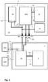
- Fig. 2is a block diagram of an energy storage in conjunction with a mobile consumer.
- a cell unit ZP suitable for this purposesupplies a rated voltage of preferably 48 V.
- the cell unit ZPis equipped with a battery management system BMS and arranged together with the latter in a housing G.
- a display device in the form of a light ring LRConnected to the housing G is a display device in the form of a light ring LR, which is fed by a light source connected in circuit terms to the battery management system BMS.
- the light ring LRcan serve as a display device for the selected engine power of the traction drive or the state of charge of the cell unit ZP.
- the light sourceis preferably a or, for example in the case of a light ring LR subdivided into several sections, a plurality of LEDs which may be selected in different colors.
- the housing Gis terminated at its ends on the one hand by a bottom plate GB and on the other hand by an input device in the form of a selector switch DS.
- the selector DSis used to adjust the engine power of the traction drive.
- the selector switch DSis designed as a detent rotary switch for three power levels.
- the selector DSalso has an off position or an on-off button.
- the bottom plate GBhas attachment means BJ, with which the energy storage is connected to a holding device on the mobile device, so the bike.
- the fastening means BJare three on a pitch circle with asymmetrical angular position to each other arranged bayonet bushings, so that the holding device of the mobile device has three arranged in a corresponding angular position and on the same pitch circle diameter bayonet pins.
- electrical contact meansare further arranged.
- the electrical contact meansconsist of a pair of high-current contacts HK, a pair of communication contacts KK and a pair of pilot contacts PK.
- the arrangement of the contact meansis exemplified and may be embodied in any suitable manner.
- the fastening means BJcan be designed both for the sole attachment of the energy store ES as well as further, then responsible for the attachment of the energy storage ES holding means exclusively for the position of the energy storage ES ES with respect to the electrical contact means.
- the mode of operation of the energy store ES according to FIG. 1will be explained with reference to the block diagram of FIG.
- the block diagram according to FIG. 2shows, in addition to the energy store ES according to the invention, a traction drive A which is connected to one another by means of the contact means for the high-current connection HK, the communication connection KK and the pilot connection PK.
- the drive-side pilot connection PKis formed as a short circuit of the pilot lines, whereby the separation of the contact means is detected when removing the energy storage ES. Because the pilot contacts PK disconnect due to their compared to the high-current contacts HK shorter length than the high-current contacts HK, they are disconnected from voltage by the battery management system BMS and a switching arc with contact firing at the high-current contacts HK avoided.
- the energy store EScomprises the cell unit ZP, which is connected to the battery management system BMS via a high-current line pair HS and a first sensor line S1. Via the sensor line S1, the voltage of the individual cells and the temperature of the cell unit are queried, and from this the charge state of the cell unit ZP is determined. With the battery management system BMS also the input device in the form of the detent rotary switch DS is connected. This connection is realized once by a second sensor line S2, which is connected to the part of the locking rotary switch DS of the on-off switch EA, and the second by the communication line pair by the locking rotary switch DS next to the actuator in the form of a Rotary knob has an electronic interface, which serves to connect the locking rotary switch DS to the communication line pair.
- the electronics of the locking rotary switch DSreceives the required operating voltage via a supply line V.
- the display device in the form of the light ring LRis connected to the battery management system BMS.
- the traction drive Aconsists, as far as is relevant to the invention, of a motor M and a control device SR, which are interconnected by means of phase current lines ME and a third sensor line S3.
- a torque sensor SDLis connected to the control device SR via a fourth sensor line S4 and a speed sensor SDR is connected via a fifth sensor line S5.
- the torque sensor SDLis arranged in the illustrated embodiment of the invention, an energy storage ES for a bicycle electric drive on a standard bottom bracket and receives via the supply line V from the controller SR its operating voltage, the speed sensor SDR may be coupled to the corresponding rear wheel.
- the communication connection usedis a serial bus system, preferably a CAN bus according to ISO 11898. Accordingly, the connected units battery management system BMS, snap-in rotary switch DS, light ring LR on the side of the energy storage ES and control device SR on the part of the traction drive A on the required for this purpose, known in the art standardized circuit and programmischen requirements.
- the userselects an assistance level, which is interpreted by the control device SR as a specification for the power consumption of the motor M, wherein the control device SR receives actual values from the connected sensors for torque SDL and speed SDR for controlling the parameters selected in the form of the selected assistance level crankshaft torque and engine speed.
- the energy store EScan be removed from the holder on the mobile device and positioned in a charging station corresponding to the contacting, which, moreover, can be configured in a known manner, in particular with respect to its electrical function.
- the energy store ESis characterized in that removal and use can be carried out with one hand and the delivery of the stored energy is controlled by means of an efficient, standardized data transfer.
- input device, display device, battery management system and cell unitare arranged in a housing and the attachment of the same is connected to a mobile consumer with little effort, the inventive energy storage is also suitable for retrofit kits or the like.
Landscapes
- Chemical & Material Sciences (AREA)
- Chemical Kinetics & Catalysis (AREA)
- Electrochemistry (AREA)
- General Chemical & Material Sciences (AREA)
- Engineering & Computer Science (AREA)
- Manufacturing & Machinery (AREA)
- Microelectronics & Electronic Packaging (AREA)
- Secondary Cells (AREA)
- Electric Propulsion And Braking For Vehicles (AREA)
- Charge And Discharge Circuits For Batteries Or The Like (AREA)
- Battery Mounting, Suspending (AREA)
Abstract
Description
Translated fromGermanEnergiespeicherenergy storage
Die Erfindung betrifft einen intelligenten Energiespeicher für mobile Verbraucher. Das Anwendungsgebiet der Erfindung sind elektrisch angetriebene Fahrzeuge, beispielsweise Zweiräder mit elektrischem Hilfsantrieb. Ein bevorzugtes Anwendungsgebiet sind Fahrräder mit elektrischem Hilfsantrieb, so genannte Pedelecs.The invention relates to an intelligent energy storage device for mobile consumers. The field of application of the invention are electrically driven vehicles, for example two-wheeled vehicles with electric auxiliary drive. A preferred field of application are bicycles with electric auxiliary drive, so-called pedelecs.
Elektrische Fahrzeugantriebe benötigen eine Energiequelle in Form einer Batterie. Aus ökonomischer und ökologischer Sicht kommen hierfür ausschließlich wieder aufladbare Ausführungen in Frage, die entweder fest im Fahrzeug verbaut oder abnehmbar ausgebildet sind. Die jeweils günstigere Variante hängt vor allem vom Fahrzeugtyp und der erforderlichen Ladekapazität ab. Ein Vorteil abnehmbar ausgebildeter Energiespeicher besteht darin, dass durch einfachen Austausch eines entladenen Energiespeichers gegen einen geladenen Energiespeicher geringere Ladekapazitäten und damit kürzere Ladezeiten und geringere Masse möglich sind, so dass der Energiespeicher als zu bewegende Masse einen geringeren Anteil der Leistung des Antriebs benötigt. Dies wirkt sich beispielsweise bei Fahrrädern mit unterstützendem Elektroantrieb auch im Muskelkraftbetrieb vorteilhaft aus, da geringere zu bewegende Masse gleichbedeutend mit leichterem Tritt ist.Electric vehicle drives require a power source in the form of a battery. From an economic and ecological point of view, only rechargeable versions are possible, which are either permanently installed in the vehicle or designed to be removable. The cheaper option depends mainly on the vehicle type and the required load capacity. An advantage of removable trained energy storage is that by simply replacing a discharged energy storage against a charged energy storage lower charging capacity and thus shorter charging times and lower mass are possible, so that the energy storage needs to be moved mass a smaller proportion of the power of the drive. This has an advantageous effect, for example, in bicycles with supporting electric drive even in muscle power operation, since lower mass to be moved is synonymous with easier kick.
Der Erfindung liegt die Aufgabe zugrunde, einen abnehmbar ausgebildeten Energiespeicher für mobile Verbraucher in Bezug auf Handhabbarkeit sowie Effizienz zu verbessern.The invention has for its object to improve a removable trained energy storage for mobile consumers in terms of manageability and efficiency.
Die Aufgabe wird mit einem Energiespeicher nach Patentanspruch 1 gelöst, der eine Zelleinheit mit angeschlossenem Batteriemanagement-System, eine mit dem Batteriemanagement-System verbundene Anzeigeeinrichtung, mit dem Batteriemanagement-System verbundene Kontaktmittel zur Verbindung mit dem mobilen Verbraucher einerseits und zum Laden der Zelleinheit andererseits wenigstens in Form von Hochstrom-Kontakten und eine mit dem Batteriemanagement-System verbundene Eingabeeinrichtung umfasst. Zelleinheit mit Batteriemanagement-System, Anzeigeeinrichtung, Eingabeeinrichtung und Kontaktmittel sind in einem Gehäuse angeordnet, das mit Befestigungsmitteln für die Befestigung an einem den Verbraucher aufweisenden Mobilgerät versehen ist. Die Befestigung erfolgt mittels einer Mehrzahl Bajonett-Verschlüsse, die in einem Gehäuseboden unsymmetrisch, d.h. auf einem Teilkreisdurchmesser unter unsymmetrischer Winkellage oder auf wenigstens zwei Teilkreisdurchmessern auch bei symmetrischer Winkellage angeordnet ist, woraus sowohl komfortable Einhand-Entnahme als auch korrekte Kontaktierung folgen.The object is achieved with an energy storage device according to claim 1, which comprises a cell unit with connected battery management system, a connected to the battery management system display device connected to the battery management system contact means for connection to the mobile consumer on the one hand and for loading the cell unit on the other hand at least in the form of high current contacts and an input device connected to the battery management system. Cell unit with battery management system, display device, input device and contact means are arranged in a housing which is provided with fastening means for attachment to a consumer having mobile device. The attachment is by means of a plurality of bayonet locks, which are asymmetrical in a housing bottom, i. is arranged on a pitch circle diameter under asymmetrical angular position or on at least two pitch diameters even at symmetrical angular position, resulting in both comfortable one-hand removal and correct contacting follow.
Vorteilhafte Weiterbildungen und Ausgestaltungen der Erfindung ergeben sich aus den Unteransprüchen. Der erfindungsgemäße Energiespeicher wird dadurch weitergebildet, dass die Anzeigeeinrichtung, die Eingabeeinrichtung und das Batteriemanagement-System an ein serielles Bussystem angeschlossen sind. Das Zugriffsmanagement des Bussystems erfolgt vorteilhaft durch Synchronisation und Identifikation der zu übertragenden Nachrichten, indem jede Einheit über eine Controllerschaltung verfügt, mittels der sie an das Bussystem angeschlossen ist. Eine bevorzugte Ausführung des Bussystems stellt beispielsweise der CAN-Bus gemäß ISO 11898 dar. Vorteilhaft ausgestaltet wird die Erfindung, indem die Eingabeeinrichtung als Wahlschalter ausgebildet ist. Dabei kann der Wahlschalter als Ein-Aus-Schalter und/oder zum stufenlosen oder diskreten Stellen eines elektrischen Parameters wie beispielsweise des Batteriestroms zum Stellen der Leistung des mobilen Verbrauchers ausgestaltet sein, indem entsprechende Nachrichten über eine das Bussystem nutzende Kommunikationsverbindung an das Batteriemanagement-System, die Anzeigeeinrichtung und eine geeignete Empfangseinrichtung des mobilen Verbrauchers übermittelt werden. Eine weitere vorteilhafte Ausgestaltung der Erfindung besteht darin, dass die Anzeigeeinrichtung als Leuchtmittel ausgebildet ist. Eine bevorzugte Ausbildung der Anzeigeeinrichtung ist dabei in Form eines Leuchtringes gegeben, der an eine oder mehrere Lichtquellen angeschlossen ist. So können bei Verwendung mehrerer Lichtquellen oder einer verschiedene Frequenzen erzeugenden Lichtquelle beispielsweise verschiedene Werte eines elektrischen Parameters, beispielsweise des Ladezustandes der Zelleinheit, oder verschiedene elektrische Parameter wie beispielsweise kritischer Ladezustand der Zelleinheit und vorgewählte Leistungsstufe symbolisch dargestellt werden. Eine weitere vorteilhafte Ausgestaltung des erfindungsgemäßen Energiespeichers besteht darin, dass die Kontaktmittel gegenüber den Hochstrom-Kontakten kürzere Pilot-Kontakte umfassen, die mit dem Batteriemanagement-System der Zelleinheit verbunden sind. Weil die Pilotkontakte somit beim Lösen des Energiespeichers vom Mobilgerät früher trennen als die Hochstromkontakte, werden diese durch das Batteriemanagement-System spannungsfrei geschaltet, wodurch ein Schaltlichtbogen mit Kontaktbrand an den Hochstrom-Kontakten vermieden wird.Advantageous developments and refinements of the invention emerge from the subclaims. The energy store according to the invention is further developed in that the display device, the input device and the battery management system are connected to a serial bus system. The access management of the bus system is advantageously carried out by synchronization and identification of the messages to be transmitted by each unit has a controller circuit, by means of which it is connected to the bus system. A preferred embodiment of the bus system, for example, represents the CAN bus according to ISO 11898. Advantageously, the invention is designed by the input device is designed as a selector switch. In this case, the selector switch can be configured as an on-off switch and / or for stepless or discrete setting of an electrical parameter such as the battery current for setting the power of the mobile consumer by sending corresponding messages to the battery management system via a communication connection using the bus system. the display device and a suitable receiving device of the mobile consumer are transmitted. A further advantageous embodiment of the invention is that the display device is designed as a lighting means. A preferred embodiment of the display device is given in the form of a light ring, which is connected to one or more light sources. Thus, when using multiple light sources or a different frequencies generating light source, for example, different values of an electrical parameter, such as the state of charge of the cell unit, or various electrical parameters such as critical state of charge of the cell unit and preselected power level can be represented symbolically. A further advantageous embodiment of the energy store according to the invention consists in that the contact means with respect to the high-current contacts comprise shorter pilot contacts, which are connected to the battery management system of the cell unit. Because the pilot contacts thus disconnect earlier than the high-current contacts when releasing the energy store from the mobile device, they are disconnected from voltage by the battery management system, whereby a switching arc with contact firing at the high-current contacts is avoided.
Ein Ausführungsbeispiel eines erfindungsgemäßen Energiespeichers wird nachfolgend anhand der Zeichnung näher erläutert. Der dargestellte Energiespeicher versorgt einen mobilen Verbraucher in Form eines Traktionsantriebes eines Mobilgerätes mit Energie. Die Zeichnung zeigt inAn embodiment of an energy storage device according to the invention will be explained in more detail with reference to the drawing. The illustrated energy storage supplies a mobile consumer in the form of a traction drive of a mobile device with energy. The drawing shows in
Fig. 1einen Energiespeicher in Halbschnittdarstellung undFig. 1 shows an energy storage in half-section view and
Fig. 2ein Blockschaltbild eines Energiespeichers in Verbindung mit einem mobilen Verbraucher.Fig. 2 is a block diagram of an energy storage in conjunction with a mobile consumer.
Fig. 1 zeigt einen Energiespeicher ES nach der Erfindung zur Energieversorgung eines Traktionsantriebes, beispielsweise eines elektrischen Fahrrad-Hilfsantriebes. Eine hierfür geeignete Zelleinheit ZP liefert eine Nennspannung von bevorzugt 48 V. Die Zelleinheit ZP ist mit einem Batteriemanagement-System BMS ausgestattet und zusammen mit diesem in einem Gehäuse G angeordnet. Mit dem Gehäuse G ist eine Anzeigeeinrichtung in Form eines Lichtrings LR verbunden, der von einer schaltungstechnisch mit dem Batteriemanagement-System BMS verbundenen Lichtquelle gespeist wird. Der Lichtring LR kann als Anzeigeeinrichtung für die gewählte Motorleistung des Traktionsantriebes oder den Ladezustand der Zelleinheit ZP dienen. Bei der Lichtquelle handelt es sich vorzugsweise um eine oder, beispielsweise im Falle eines in mehrere Abschnitte unterteilten Lichtringes LR, eine Mehrzahl LED, die verschiedenfarbig ausgewählt sein können. Das Gehäuse G ist an seinen Enden einerseits von einer Bodenplatte GB und andererseits von einer Eingabeeinrichtung in Form eines Wahlschalters DS abgeschlossen. Der Wahlschalter DS dient zur Einstellung der Motorleistung des Traktionsantriebes. Vorzugsweise ist der Wahlschalter DS als Rast-Drehschalter für drei Leistungsstufen ausgeführt. Der Wahlschalter DS verfügt zudem über eine Aus-Schaltstellung oder einen Ein-Aus-Schaltknopf. Die Bodenplatte GB weist Befestigungsmittel BJ auf, mit denen der Energiespeicher mit einer Haltevorrichtung am Mobilgerät, also dem Fahrrad, verbunden wird. Die Befestigungsmittel BJ sind drei auf einem Teilkreis mit unsymmetrischer Winkellage zueinander angeordnete Bajonettbuchsen, so dass die Haltevorrichtung des Mobilgerätes drei in entsprechender Winkellage und auf gleichem Teilkreisdurchmesser angeordnete Bajonettstifte aufweist. In der Bodenplatte GB sind weiterhin elektrische Kontaktmittel angeordnet. Die elektrischen Kontaktmittel bestehen aus einem Paar Hochstrom-Kontakten HK, einem Paar Kommunikations-Kontakten KK und einem Paar Pilot-Kontakten PK. Die Anordnung der Kontaktmittel ist beispielhaft dargestellt und kann in jeder geeigneten Weise ausgeführt sein. Die Befestigungsmittel BJ können sowohl zur alleinigen Befestigung des Energiespeichers ES ausgelegt sein als auch neben weiteren, dann für die Befestigung des Energiespeichers ES zuständigen Haltemitteln ausschließlich zur Lagedefinition des Energiespeichers ES bezüglich der elektrischen Kontaktmittel dienen.1 shows an energy store ES according to the invention for supplying energy to a traction drive, for example an electric bicycle auxiliary drive. A cell unit ZP suitable for this purpose supplies a rated voltage of preferably 48 V. The cell unit ZP is equipped with a battery management system BMS and arranged together with the latter in a housing G. Connected to the housing G is a display device in the form of a light ring LR, which is fed by a light source connected in circuit terms to the battery management system BMS. The light ring LR can serve as a display device for the selected engine power of the traction drive or the state of charge of the cell unit ZP. The light source is preferably a or, for example in the case of a light ring LR subdivided into several sections, a plurality of LEDs which may be selected in different colors. The housing G is terminated at its ends on the one hand by a bottom plate GB and on the other hand by an input device in the form of a selector switch DS. The selector DS is used to adjust the engine power of the traction drive. Preferably, the selector switch DS is designed as a detent rotary switch for three power levels. The selector DS also has an off position or an on-off button. The bottom plate GB has attachment means BJ, with which the energy storage is connected to a holding device on the mobile device, so the bike. The fastening means BJ are three on a pitch circle with asymmetrical angular position to each other arranged bayonet bushings, so that the holding device of the mobile device has three arranged in a corresponding angular position and on the same pitch circle diameter bayonet pins. In the bottom plate GB electrical contact means are further arranged. The electrical contact means consist of a pair of high-current contacts HK, a pair of communication contacts KK and a pair of pilot contacts PK. The arrangement of the contact means is exemplified and may be embodied in any suitable manner. The fastening means BJ can be designed both for the sole attachment of the energy store ES as well as further, then responsible for the attachment of the energy storage ES holding means exclusively for the position of the energy storage ES ES with respect to the electrical contact means.
Die Wirkungsweise des Energiespeichers ES gemäß Fig. 1 wird anhand des Blockschaltbildes nach Fig. 2 erläutert. Das Blockschaltbild nach Fig. 2 zeigt neben dem erfindungsgemäßen Energiespeicher ES einen Traktionsantrieb A, die mittels der Kontaktmittel für die Hochstrom-Verbindung HK, die Kommunikations-Verbindung KK und die Pilot-Verbindung PK miteinander verbunden sind. Die antriebsseitige Pilot-Verbindung PK ist als Kurzschluss der Pilotleitungen ausgebildet, wodurch beim Entnehmen des Energiespeichers ES das Trennen der Kontaktmittel erkannt wird. Weil die Pilot-Kontakte PK aufgrund ihrer gegenüber den Hochstrom-Kontakten HK geringeren Länge früher trennen als die Hochstrom-Kontakte HK, werden diese durch das Batteriemanagement-System BMS spannungsfrei geschaltet und ein Schaltlichtbogen mit Kontaktbrand an den Hochstrom-Kontakten HK vermieden.Der Energiespeicher ES umfasst die Zelleinheit ZP, die mit dem Batteriemanagement-System BMS über ein Hochstrom-Leitungspaar HS und eine erste Sensorleitung S1 verbunden ist. Über die Sensorleitung S1 werden Spannung der Einzelzellen und Temperatur der Zelleinheit abgefragt und daraus der Ladezustand der Zelleinheit ZP bestimmt. Mit dem Batteriemanagement-System BMS ist ferner die Eingabeeinrichtung in Form des Rast-Drehschalters DS verbunden. Diese Verbindung wird einmal durch eine zweite Sensorleitung S2, an die seitens des Rast-Drehschalters DS der Ein-Aus-Schalter EA angeschlossen ist, und zum zweiten durch das Kommunikations-Leitungspaar realisiert, indem der Rast-Drehschalter DS neben der Betätigungsvorrichtung in Form eines Drehknopfes über eine elektronische Schnittstelle verfügt, die dem Anschluss des Rast-Drehschalters DS an das Kommunikations-Leitungspaar dient. Die Elektronik des Rast-Drehschalters DS erhält über eine Versorgungsleitung V die erforderliche Betriebsspannung. In gleicher Weise, nämlich mittels des Kommunikations-Leitungspaares und einer Versorgungsleitung V ist die Anzeigeeinrichtung in Form des Lichtrings LR an das Batteriemanagement-System BMS angeschlossen. Der Traktionsantrieb A besteht, soweit dies für die Erfindung von Bedeutung ist, aus einem Motor M und einer Regeleinrichtung SR, die mittels Phasenstromleitungen ME und einer dritten Sensorleitung S3 miteinander verbunden sind. An die Regeleinrichtung SR sind ferner über eine vierte Sensorleitung S4 ein Drehmomentsensor SDL und über eine fünfte Sensorleitung S5 ein Drehzahlsensor SDR angeschlossen. Der Drehmomentsensor SDL ist in der dargestellten Ausführung der Erfindung, einem Energiespeicher ES für einen Fahrrad-Elektroantrieb, an einem Standard-Tretlager angeordnet und erhält über die Versorgungsleitung V von der Regeleinrichtung SR seine Betriebsspannung, der Drehzahlsensor SDR kann entsprechend mit dem Hinterrad gekoppelt sein. Als Kommunikations-Verbindung kommt ein serielles Bussystem, vorzugsweise ein CAN-Bus gemäß ISO 11898 zur Anwendung. Demgemäß verfügen die angeschlossenen Einheiten Batteriemanagement-System BMS, Rast-Drehschalter DS, Lichtring LR auf Seiten des Energiespeichers ES und Regeleinrichtung SR auf Seiten des Traktionsantriebs A über die hierfür erforderlichen, dem Fachmann bekannten standardisierten schaltungs- und programmtechnischen Voraussetzungen. Mittels des Rast-Drehschalters DS wählt der Benutzer eine Unterstützungsstufe aus,die von der Regeleinrichtung SR als Vorgabe für die Leistungsaufnahme des Motors M interpretiert wird, wobei die Regeleinrichtung SR zur Steuerung der in Form der gewählten Unterstützungsstufe gewählten Parameter Kurbelwellendrehmoment und Motordrehzahl Istwerte von den angeschlossenen Sensoren für Drehmoment SDL und Drehzahl SDR erhält. Zur Aufladung der Zelleinheit ZP kann der Energiespeicher ES aus der Halterung am Mobilgerät entnommen und in einer bezüglich der Kontaktierung entsprechenden Ladestation positioniert werden, die im Übrigen, insbesondere hinsichtlich ihrer elektrischen Funktion in bekannter Weise ausgebildet sein kann.The mode of operation of the energy store ES according to FIG. 1 will be explained with reference to the block diagram of FIG. The block diagram according to FIG. 2 shows, in addition to the energy store ES according to the invention, a traction drive A which is connected to one another by means of the contact means for the high-current connection HK, the communication connection KK and the pilot connection PK. The drive-side pilot connection PK is formed as a short circuit of the pilot lines, whereby the separation of the contact means is detected when removing the energy storage ES. Because the pilot contacts PK disconnect due to their compared to the high-current contacts HK shorter length than the high-current contacts HK, they are disconnected from voltage by the battery management system BMS and a switching arc with contact firing at the high-current contacts HK avoided. The energy store ES comprises the cell unit ZP, which is connected to the battery management system BMS via a high-current line pair HS and a first sensor line S1. Via the sensor line S1, the voltage of the individual cells and the temperature of the cell unit are queried, and from this the charge state of the cell unit ZP is determined. With the battery management system BMS also the input device in the form of the detent rotary switch DS is connected. This connection is realized once by a second sensor line S2, which is connected to the part of the locking rotary switch DS of the on-off switch EA, and the second by the communication line pair by the locking rotary switch DS next to the actuator in the form of a Rotary knob has an electronic interface, which serves to connect the locking rotary switch DS to the communication line pair. The electronics of the locking rotary switch DS receives the required operating voltage via a supply line V. In the same way, namely by means of the communication line pair and a supply line V, the display device in the form of the light ring LR is connected to the battery management system BMS. The traction drive A consists, as far as is relevant to the invention, of a motor M and a control device SR, which are interconnected by means of phase current lines ME and a third sensor line S3. Furthermore, a torque sensor SDL is connected to the control device SR via a fourth sensor line S4 and a speed sensor SDR is connected via a fifth sensor line S5. The torque sensor SDL is arranged in the illustrated embodiment of the invention, an energy storage ES for a bicycle electric drive on a standard bottom bracket and receives via the supply line V from the controller SR its operating voltage, the speed sensor SDR may be coupled to the corresponding rear wheel. The communication connection used is a serial bus system, preferably a CAN bus according to ISO 11898. Accordingly, the connected units battery management system BMS, snap-in rotary switch DS, light ring LR on the side of the energy storage ES and control device SR on the part of the traction drive A on the required for this purpose, known in the art standardized circuit and programmtechnischen requirements. By means of the detent rotary switch DS, the user selects an assistance level, which is interpreted by the control device SR as a specification for the power consumption of the motor M, wherein the control device SR receives actual values from the connected sensors for torque SDL and speed SDR for controlling the parameters selected in the form of the selected assistance level crankshaft torque and engine speed. In order to charge the cell unit ZP, the energy store ES can be removed from the holder on the mobile device and positioned in a charging station corresponding to the contacting, which, moreover, can be configured in a known manner, in particular with respect to its electrical function.
Der erfindungsgemäße Energiespeicher ES zeichnet sich dadurch aus, dass Entnahme und Einsatz einhändig erfolgen können und die Abgabe der gespeicherten Energie mittels eines effizienten, standardisierten Datentransfers gesteuert wird. Indem Eingabeeinrichtung, Anzeigeeinrichtung, Batteriemanagement-System und Zelleinheit in einem Gehäuse angeordnet sind und die Befestigung desselben an einem mobilen Verbraucher mit geringem Aufwand verbunden ist, eignet sich der erfindungsgemäße Energiespeicher zudem auch für Nachrüstbausätze oder ähnliches.The energy store ES according to the invention is characterized in that removal and use can be carried out with one hand and the delivery of the stored energy is controlled by means of an efficient, standardized data transfer. By input device, display device, battery management system and cell unit are arranged in a housing and the attachment of the same is connected to a mobile consumer with little effort, the inventive energy storage is also suitable for retrofit kits or the like.
BezugszeichenlisteLIST OF REFERENCE NUMBERS
ESEnergiespeicherES energy storage
LRAnzeigeeinrichtung, LichtringLR display, light ring
BMSBatteriemanagement-SystemBMS battery management system
ZPZelleinheitZP cell unit
DSEingabeeinrichtung, DrehschalterDS input device, rotary switch
GGehäuseG housing
GBGehäusebodenGB caseback
BJBajonettbuchsenBJ bayonet sockets
HKHochstrom-KontakteHK high-current contacts
KKKommunikations-KontakteKK communication contacts
PKPilot-KontaktePK pilot contacts
EAEin-Aus-SchalterEA on-off switch
SnSensorleitungSn sensor line
VBetriebsspannungsleitungV operating voltage line
HSHochstrom-LeitungenHS high current lines
AAntriebA drive
Mmobiler Verbraucher, MotorM mobile consumer, engine
SRRegeleinrichtungSR control device
SDLDrehmoment-SensorSDL torque sensor
SDRDrehzahl-SensorSDR speed sensor
MEPhasenstromleitungenME phase power lines
Claims (6)
Translated fromGermanPriority Applications (4)
| Application Number | Priority Date | Filing Date | Title |
|---|---|---|---|
| DK15744532.1TDK3172791T3 (en) | 2014-07-24 | 2015-07-23 | ENERGY STORAGE |
| US15/327,673US20170207502A1 (en) | 2014-07-24 | 2015-07-23 | Energy store |
| EP15744532.1AEP3172791B1 (en) | 2014-07-24 | 2015-07-23 | Energy storage device |
| CN201580046396.6ACN106663753B (en) | 2014-07-24 | 2015-07-23 | energy storage |
Applications Claiming Priority (2)
| Application Number | Priority Date | Filing Date | Title |
|---|---|---|---|
| DE102014110428.5 | 2014-07-24 | ||
| DE102014110428.5ADE102014110428A1 (en) | 2014-07-24 | 2014-07-24 | energy storage |
Publications (1)
| Publication Number | Publication Date |
|---|---|
| WO2016012546A1true WO2016012546A1 (en) | 2016-01-28 |
Family
ID=53762166
Family Applications (1)
| Application Number | Title | Priority Date | Filing Date |
|---|---|---|---|
| PCT/EP2015/066892WO2016012546A1 (en) | 2014-07-24 | 2015-07-23 | Energy store |
Country Status (7)
| Country | Link |
|---|---|
| US (1) | US20170207502A1 (en) |
| EP (1) | EP3172791B1 (en) |
| CN (1) | CN106663753B (en) |
| DE (1) | DE102014110428A1 (en) |
| DK (1) | DK3172791T3 (en) |
| TW (1) | TWI686980B (en) |
| WO (1) | WO2016012546A1 (en) |
Citations (9)
| Publication number | Priority date | Publication date | Assignee | Title |
|---|---|---|---|---|
| GB167231A (en)* | 1920-04-27 | 1921-07-27 | Robert Kessen Winning | Improvements in or relating to electric switches and locking devices therefor |
| US5773962A (en)* | 1995-01-17 | 1998-06-30 | Norvik Traction Inc. | Battery energy monitoring circuits |
| JPH1166941A (en)* | 1997-08-11 | 1999-03-09 | Matsushita Electric Works Ltd | Lighting fitting |
| DE202010013724U1 (en)* | 2010-09-29 | 2010-11-25 | Ips Integrated Power Solutions Ag | Battery pack for electric vehicles |
| DE102010007076A1 (en)* | 2010-02-06 | 2011-08-11 | Fraunhofer-Gesellschaft zur Förderung der angewandten Forschung e.V., 80686 | Electric energy storage |
| US20120326665A1 (en)* | 2009-11-27 | 2012-12-27 | Xuejun Yin | Method for quickly supplying electric energy to electric vehicle and power supply device thereof |
| WO2013164120A1 (en)* | 2012-04-30 | 2013-11-07 | Robert Bosch Gmbh | Method and device for triggering at least one safety function in the event of a safety-critical condition of an electrochemical energy store, and electrochemical energy store system |
| DE102012017190A1 (en)* | 2012-08-30 | 2014-03-06 | Daimler Ag | Electrochemical energy storage cell e.g. pouch cell, for use in lithium ion battery for supplying power to drive motor car, has measuring device detecting operational parameter and/or operational parameter alteration of functioning layer |
| CN103682482A (en)* | 2013-11-22 | 2014-03-26 | 超威电源有限公司 | Wireless intelligent battery |
Family Cites Families (10)
| Publication number | Priority date | Publication date | Assignee | Title |
|---|---|---|---|---|
| CN2295665Y (en)* | 1996-09-10 | 1998-10-28 | 上海新联电动车公司 | Mounting/dismounting device for battery box of electric bicycle |
| DE10110046A1 (en)* | 2001-03-02 | 2002-09-05 | Bosch Gmbh Robert | Switching controller for electrical equipment in vehicle, has detector for current passing through switches to determine their control |
| CN1814492A (en)* | 2005-02-03 | 2006-08-09 | 王树洲 | Bicycle power generating device and complete lamp and bell |
| WO2009035531A2 (en)* | 2007-09-07 | 2009-03-19 | Johnson Controls - Saft Advanced Power Solutions Llc | Battery charging system |
| CN102084517A (en)* | 2008-05-15 | 2011-06-01 | 江森自控帅福得先进能源动力系统有限责任公司 | Battery system |
| DE102010012154A1 (en)* | 2010-03-20 | 2011-09-22 | Audi Ag | Method for checking a state of a circuit of a motor vehicle |
| WO2012062255A2 (en)* | 2010-11-02 | 2012-05-18 | Voltabatterien Gmbh | Inherently safe modular battery for accident-prone applications |
| CN202333005U (en)* | 2011-11-25 | 2012-07-11 | 浙江诺力机械股份有限公司 | Anti-falling device capable of changing storage battery rapidly |
| CN202923825U (en)* | 2012-11-23 | 2013-05-08 | 深圳市喜德盛自行车有限公司 | Power supply installation device of electric bicycle |
| CN203312869U (en)* | 2013-06-18 | 2013-11-27 | 白明远 | Vehicle-mounted mobile power supply |
- 2014
- 2014-07-24DEDE102014110428.5Apatent/DE102014110428A1/enactivePending
- 2015
- 2015-07-23CNCN201580046396.6Apatent/CN106663753B/enactiveActive
- 2015-07-23DKDK15744532.1Tpatent/DK3172791T3/enactive
- 2015-07-23EPEP15744532.1Apatent/EP3172791B1/enactiveActive
- 2015-07-23WOPCT/EP2015/066892patent/WO2016012546A1/enactiveApplication Filing
- 2015-07-23USUS15/327,673patent/US20170207502A1/ennot_activeAbandoned
- 2015-07-24TWTW104124103Apatent/TWI686980B/enactive
Patent Citations (9)
| Publication number | Priority date | Publication date | Assignee | Title |
|---|---|---|---|---|
| GB167231A (en)* | 1920-04-27 | 1921-07-27 | Robert Kessen Winning | Improvements in or relating to electric switches and locking devices therefor |
| US5773962A (en)* | 1995-01-17 | 1998-06-30 | Norvik Traction Inc. | Battery energy monitoring circuits |
| JPH1166941A (en)* | 1997-08-11 | 1999-03-09 | Matsushita Electric Works Ltd | Lighting fitting |
| US20120326665A1 (en)* | 2009-11-27 | 2012-12-27 | Xuejun Yin | Method for quickly supplying electric energy to electric vehicle and power supply device thereof |
| DE102010007076A1 (en)* | 2010-02-06 | 2011-08-11 | Fraunhofer-Gesellschaft zur Förderung der angewandten Forschung e.V., 80686 | Electric energy storage |
| DE202010013724U1 (en)* | 2010-09-29 | 2010-11-25 | Ips Integrated Power Solutions Ag | Battery pack for electric vehicles |
| WO2013164120A1 (en)* | 2012-04-30 | 2013-11-07 | Robert Bosch Gmbh | Method and device for triggering at least one safety function in the event of a safety-critical condition of an electrochemical energy store, and electrochemical energy store system |
| DE102012017190A1 (en)* | 2012-08-30 | 2014-03-06 | Daimler Ag | Electrochemical energy storage cell e.g. pouch cell, for use in lithium ion battery for supplying power to drive motor car, has measuring device detecting operational parameter and/or operational parameter alteration of functioning layer |
| CN103682482A (en)* | 2013-11-22 | 2014-03-26 | 超威电源有限公司 | Wireless intelligent battery |
Also Published As
| Publication number | Publication date |
|---|---|
| DE102014110428A1 (en) | 2016-01-28 |
| TW201613169A (en) | 2016-04-01 |
| DK3172791T3 (en) | 2019-04-23 |
| EP3172791A1 (en) | 2017-05-31 |
| CN106663753B (en) | 2020-01-17 |
| EP3172791B1 (en) | 2019-01-16 |
| TWI686980B (en) | 2020-03-01 |
| CN106663753A (en) | 2017-05-10 |
| US20170207502A1 (en) | 2017-07-20 |
Similar Documents
| Publication | Publication Date | Title |
|---|---|---|
| EP3209518B1 (en) | Method for operating an energy storage device in a motor vehicle, and motor vehicle | |
| DE102014004790B4 (en) | Method for operating an energy storage device in a motor vehicle and motor vehicle | |
| DE102006061270B4 (en) | Battery pack and battery module | |
| EP3274217A1 (en) | Energy accumulator device | |
| DE102013200763A1 (en) | SYSTEM AND METHOD FOR VEHICLE ENERGY MANAGEMENT | |
| DE102016203427A1 (en) | Battery pack for a hand tool | |
| DE102013113182A1 (en) | Energy storage device | |
| DE102018210524A1 (en) | Process for charging battery packs for power tools and charger for carrying out the process | |
| EP3052337B1 (en) | Device for supplying a voltage to an electric vehicle comprising a permanent main battery and a replaceable auxiliary battery | |
| DE102017010998A1 (en) | Energy storage device and energy systems for a motor vehicle | |
| DE102012201827A1 (en) | Method and device for discharging a DC link of a voltage network | |
| DE102015214732A1 (en) | Method for operating an energy storage device and motor vehicle with an energy storage device | |
| DE10313752B4 (en) | Device and method for charging batteries of a multi-voltage electrical system of a motor vehicle | |
| DE102011077719A1 (en) | Power supply unit for power supply network used in motor vehicle, has connecting unit which is connected to tap so that sum of partial voltages between tap and terminal poles is measured | |
| DE102019207355A1 (en) | Battery for a motor vehicle, motor vehicle and method for operating a battery | |
| WO2011061002A1 (en) | Bicycle having an electrical auxiliary drive | |
| DE102018006691A1 (en) | battery system | |
| WO2019101443A1 (en) | Method for operating an electrical energy storage device for a motor vehicle, and corresponding energy storage device | |
| WO2019121418A1 (en) | Multiple-battery adapter for establishing an electrical connection between at least two traction batteries on the one hand and a drive unit of an electric bicycle on the other hand | |
| DE102010061477A1 (en) | Method and device for controlling a drive train of a hybrid vehicle | |
| DE102017123071A1 (en) | Supply of low-voltage on-board networks of vehicles with electric drive | |
| EP2789044B1 (en) | Method for operating a battery | |
| EP2977256B1 (en) | Method for controlling a lithium ion battery of an industrial truck | |
| EP3172791B1 (en) | Energy storage device | |
| DE102010017439A1 (en) | Energy balancing circuit configuration for, e.g. traction accumulator of vehicle, has chargers to perform charging process of cells of energy storage unit using balancing currents, with smaller load |
Legal Events
| Date | Code | Title | Description |
|---|---|---|---|
| 121 | Ep: the epo has been informed by wipo that ep was designated in this application | Ref document number:15744532 Country of ref document:EP Kind code of ref document:A1 | |
| WWE | Wipo information: entry into national phase | Ref document number:15327673 Country of ref document:US | |
| NENP | Non-entry into the national phase | Ref country code:DE | |
| REEP | Request for entry into the european phase | Ref document number:2015744532 Country of ref document:EP | |
| WWE | Wipo information: entry into national phase | Ref document number:2015744532 Country of ref document:EP |