WO2015190311A1 - Heads-up display device - Google Patents
Heads-up display deviceDownload PDFInfo
- Publication number
- WO2015190311A1 WO2015190311A1PCT/JP2015/065494JP2015065494WWO2015190311A1WO 2015190311 A1WO2015190311 A1WO 2015190311A1JP 2015065494 WJP2015065494 WJP 2015065494WWO 2015190311 A1WO2015190311 A1WO 2015190311A1
- Authority
- WO
- WIPO (PCT)
- Prior art keywords
- projection
- display device
- head
- unit
- light
- Prior art date
Links
Images


Classifications
- G—PHYSICS
- G02—OPTICS
- G02B—OPTICAL ELEMENTS, SYSTEMS OR APPARATUS
- G02B27/00—Optical systems or apparatus not provided for by any of the groups G02B1/00 - G02B26/00, G02B30/00
- G02B27/01—Head-up displays
- G02B27/0149—Head-up displays characterised by mechanical features
- B—PERFORMING OPERATIONS; TRANSPORTING
- B60—VEHICLES IN GENERAL
- B60K—ARRANGEMENT OR MOUNTING OF PROPULSION UNITS OR OF TRANSMISSIONS IN VEHICLES; ARRANGEMENT OR MOUNTING OF PLURAL DIVERSE PRIME-MOVERS IN VEHICLES; AUXILIARY DRIVES FOR VEHICLES; INSTRUMENTATION OR DASHBOARDS FOR VEHICLES; ARRANGEMENTS IN CONNECTION WITH COOLING, AIR INTAKE, GAS EXHAUST OR FUEL SUPPLY OF PROPULSION UNITS IN VEHICLES
- B60K35/00—Instruments specially adapted for vehicles; Arrangement of instruments in or on vehicles
- B60K35/10—Input arrangements, i.e. from user to vehicle, associated with vehicle functions or specially adapted therefor
- B—PERFORMING OPERATIONS; TRANSPORTING
- B60—VEHICLES IN GENERAL
- B60K—ARRANGEMENT OR MOUNTING OF PROPULSION UNITS OR OF TRANSMISSIONS IN VEHICLES; ARRANGEMENT OR MOUNTING OF PLURAL DIVERSE PRIME-MOVERS IN VEHICLES; AUXILIARY DRIVES FOR VEHICLES; INSTRUMENTATION OR DASHBOARDS FOR VEHICLES; ARRANGEMENTS IN CONNECTION WITH COOLING, AIR INTAKE, GAS EXHAUST OR FUEL SUPPLY OF PROPULSION UNITS IN VEHICLES
- B60K35/00—Instruments specially adapted for vehicles; Arrangement of instruments in or on vehicles
- B60K35/20—Output arrangements, i.e. from vehicle to user, associated with vehicle functions or specially adapted therefor
- B60K35/21—Output arrangements, i.e. from vehicle to user, associated with vehicle functions or specially adapted therefor using visual output, e.g. blinking lights or matrix displays
- B60K35/23—Head-up displays [HUD]
- B60K35/233—Head-up displays [HUD] controlling the size or position in display areas of virtual images depending on the condition of the vehicle or the driver
- B—PERFORMING OPERATIONS; TRANSPORTING
- B60—VEHICLES IN GENERAL
- B60K—ARRANGEMENT OR MOUNTING OF PROPULSION UNITS OR OF TRANSMISSIONS IN VEHICLES; ARRANGEMENT OR MOUNTING OF PLURAL DIVERSE PRIME-MOVERS IN VEHICLES; AUXILIARY DRIVES FOR VEHICLES; INSTRUMENTATION OR DASHBOARDS FOR VEHICLES; ARRANGEMENTS IN CONNECTION WITH COOLING, AIR INTAKE, GAS EXHAUST OR FUEL SUPPLY OF PROPULSION UNITS IN VEHICLES
- B60K35/00—Instruments specially adapted for vehicles; Arrangement of instruments in or on vehicles
- B60K35/80—Arrangements for controlling instruments
- B60K35/81—Arrangements for controlling instruments for controlling displays
- G—PHYSICS
- G02—OPTICS
- G02B—OPTICAL ELEMENTS, SYSTEMS OR APPARATUS
- G02B27/00—Optical systems or apparatus not provided for by any of the groups G02B1/00 - G02B26/00, G02B30/00
- G02B27/01—Head-up displays
- G02B27/0101—Head-up displays characterised by optical features
- G—PHYSICS
- G03—PHOTOGRAPHY; CINEMATOGRAPHY; ANALOGOUS TECHNIQUES USING WAVES OTHER THAN OPTICAL WAVES; ELECTROGRAPHY; HOLOGRAPHY
- G03B—APPARATUS OR ARRANGEMENTS FOR TAKING PHOTOGRAPHS OR FOR PROJECTING OR VIEWING THEM; APPARATUS OR ARRANGEMENTS EMPLOYING ANALOGOUS TECHNIQUES USING WAVES OTHER THAN OPTICAL WAVES; ACCESSORIES THEREFOR
- G03B21/00—Projectors or projection-type viewers; Accessories therefor
- G03B21/14—Details
- G03B21/142—Adjusting of projection optics
- G—PHYSICS
- G03—PHOTOGRAPHY; CINEMATOGRAPHY; ANALOGOUS TECHNIQUES USING WAVES OTHER THAN OPTICAL WAVES; ELECTROGRAPHY; HOLOGRAPHY
- G03B—APPARATUS OR ARRANGEMENTS FOR TAKING PHOTOGRAPHS OR FOR PROJECTING OR VIEWING THEM; APPARATUS OR ARRANGEMENTS EMPLOYING ANALOGOUS TECHNIQUES USING WAVES OTHER THAN OPTICAL WAVES; ACCESSORIES THEREFOR
- G03B21/00—Projectors or projection-type viewers; Accessories therefor
- G03B21/14—Details
- G03B21/28—Reflectors in projection beam
- G—PHYSICS
- G06—COMPUTING OR CALCULATING; COUNTING
- G06F—ELECTRIC DIGITAL DATA PROCESSING
- G06F3/00—Input arrangements for transferring data to be processed into a form capable of being handled by the computer; Output arrangements for transferring data from processing unit to output unit, e.g. interface arrangements
- G06F3/01—Input arrangements or combined input and output arrangements for interaction between user and computer
- G06F3/011—Arrangements for interaction with the human body, e.g. for user immersion in virtual reality
- G06F3/013—Eye tracking input arrangements
- G—PHYSICS
- G09—EDUCATION; CRYPTOGRAPHY; DISPLAY; ADVERTISING; SEALS
- G09G—ARRANGEMENTS OR CIRCUITS FOR CONTROL OF INDICATING DEVICES USING STATIC MEANS TO PRESENT VARIABLE INFORMATION
- G09G3/00—Control arrangements or circuits, of interest only in connection with visual indicators other than cathode-ray tubes
- G09G3/001—Control arrangements or circuits, of interest only in connection with visual indicators other than cathode-ray tubes using specific devices not provided for in groups G09G3/02 - G09G3/36, e.g. using an intermediate record carrier such as a film slide; Projection systems; Display of non-alphanumerical information, solely or in combination with alphanumerical information, e.g. digital display on projected diapositive as background
- G09G3/002—Control arrangements or circuits, of interest only in connection with visual indicators other than cathode-ray tubes using specific devices not provided for in groups G09G3/02 - G09G3/36, e.g. using an intermediate record carrier such as a film slide; Projection systems; Display of non-alphanumerical information, solely or in combination with alphanumerical information, e.g. digital display on projected diapositive as background to project the image of a two-dimensional display, such as an array of light emitting or modulating elements or a CRT
- G—PHYSICS
- G09—EDUCATION; CRYPTOGRAPHY; DISPLAY; ADVERTISING; SEALS
- G09G—ARRANGEMENTS OR CIRCUITS FOR CONTROL OF INDICATING DEVICES USING STATIC MEANS TO PRESENT VARIABLE INFORMATION
- G09G3/00—Control arrangements or circuits, of interest only in connection with visual indicators other than cathode-ray tubes
- G09G3/02—Control arrangements or circuits, of interest only in connection with visual indicators other than cathode-ray tubes by tracing or scanning a light beam on a screen
- B—PERFORMING OPERATIONS; TRANSPORTING
- B60—VEHICLES IN GENERAL
- B60K—ARRANGEMENT OR MOUNTING OF PROPULSION UNITS OR OF TRANSMISSIONS IN VEHICLES; ARRANGEMENT OR MOUNTING OF PLURAL DIVERSE PRIME-MOVERS IN VEHICLES; AUXILIARY DRIVES FOR VEHICLES; INSTRUMENTATION OR DASHBOARDS FOR VEHICLES; ARRANGEMENTS IN CONNECTION WITH COOLING, AIR INTAKE, GAS EXHAUST OR FUEL SUPPLY OF PROPULSION UNITS IN VEHICLES
- B60K2360/00—Indexing scheme associated with groups B60K35/00 or B60K37/00 relating to details of instruments or dashboards
- B60K2360/20—Optical features of instruments
- B60K2360/29—Holographic features
- B—PERFORMING OPERATIONS; TRANSPORTING
- B60—VEHICLES IN GENERAL
- B60K—ARRANGEMENT OR MOUNTING OF PROPULSION UNITS OR OF TRANSMISSIONS IN VEHICLES; ARRANGEMENT OR MOUNTING OF PLURAL DIVERSE PRIME-MOVERS IN VEHICLES; AUXILIARY DRIVES FOR VEHICLES; INSTRUMENTATION OR DASHBOARDS FOR VEHICLES; ARRANGEMENTS IN CONNECTION WITH COOLING, AIR INTAKE, GAS EXHAUST OR FUEL SUPPLY OF PROPULSION UNITS IN VEHICLES
- B60K2360/00—Indexing scheme associated with groups B60K35/00 or B60K37/00 relating to details of instruments or dashboards
- B60K2360/20—Optical features of instruments
- B60K2360/33—Illumination features
- B60K2360/334—Projection means
- B—PERFORMING OPERATIONS; TRANSPORTING
- B60—VEHICLES IN GENERAL
- B60K—ARRANGEMENT OR MOUNTING OF PROPULSION UNITS OR OF TRANSMISSIONS IN VEHICLES; ARRANGEMENT OR MOUNTING OF PLURAL DIVERSE PRIME-MOVERS IN VEHICLES; AUXILIARY DRIVES FOR VEHICLES; INSTRUMENTATION OR DASHBOARDS FOR VEHICLES; ARRANGEMENTS IN CONNECTION WITH COOLING, AIR INTAKE, GAS EXHAUST OR FUEL SUPPLY OF PROPULSION UNITS IN VEHICLES
- B60K2360/00—Indexing scheme associated with groups B60K35/00 or B60K37/00 relating to details of instruments or dashboards
- B60K2360/20—Optical features of instruments
- B60K2360/33—Illumination features
- B60K2360/347—Optical elements for superposition of display information
- G—PHYSICS
- G02—OPTICS
- G02B—OPTICAL ELEMENTS, SYSTEMS OR APPARATUS
- G02B27/00—Optical systems or apparatus not provided for by any of the groups G02B1/00 - G02B26/00, G02B30/00
- G02B27/01—Head-up displays
- G02B27/0101—Head-up displays characterised by optical features
- G02B2027/0127—Head-up displays characterised by optical features comprising devices increasing the depth of field
- G—PHYSICS
- G02—OPTICS
- G02B—OPTICAL ELEMENTS, SYSTEMS OR APPARATUS
- G02B27/00—Optical systems or apparatus not provided for by any of the groups G02B1/00 - G02B26/00, G02B30/00
- G02B27/01—Head-up displays
- G02B27/0101—Head-up displays characterised by optical features
- G02B2027/0145—Head-up displays characterised by optical features creating an intermediate image
- G—PHYSICS
- G02—OPTICS
- G02B—OPTICAL ELEMENTS, SYSTEMS OR APPARATUS
- G02B27/00—Optical systems or apparatus not provided for by any of the groups G02B1/00 - G02B26/00, G02B30/00
- G02B27/01—Head-up displays
- G02B27/0149—Head-up displays characterised by mechanical features
- G02B2027/0154—Head-up displays characterised by mechanical features with movable elements
- G02B2027/0159—Head-up displays characterised by mechanical features with movable elements with mechanical means other than scaning means for positioning the whole image
Definitions
- the present inventionrelates to a head-up display device that superimposes an image on a real scene for visual recognition.
- the head-up display devicegenerates an augmented reality (AR: Augmented Reality) with information added to the real scene by displaying a virtual image superimposed on the real scene ahead of the host vehicle, and moves the line of sight of the observer driving the vehicle. While providing as much information as possible to the observer while suppressing as much as possible, it contributes to safe and comfortable vehicle operation.
- ARAugmented Reality
- Patent Document 1includes a projection unit that projects a light beam at a predetermined projection position and visually recognizes the virtual image, and detects the viewpoint position of the observer.
- An image display deviceis disclosed in which the movable mirror is rotated based on the detected viewpoint position to direct the light beam emitted from the projection unit to the viewpoint position of the observer.
- Patent Document 2by adjusting the angle while moving the display and the reflecting portion along the arc, the image light emitted from the display is directed to the viewpoint position of the observer, and the display A display device is disclosed that allows an observer to visually recognize image light from the projector.
- each image light N directed toward an observer having a different viewpoint heightis light emitted in a different direction from the display surface 101 a of the display device 101.
- the light distribution characteristic of the image light N emitted from the display device 101it is necessary to make the light distribution characteristic of the image light N emitted from the display device 101 constant over a wide range. Therefore, it is necessary to increase the light distribution angle (diffusion angle) of the image light N emitted from the display device 101 (decrease the directivity), and the efficiency of the display device 101 decreases.
- Patent Document 2in order to direct the image light to the observer's viewpoint position, a complicated and large moving mechanism is required to move the display device, which is an electronic device, along the arc. Met.
- the present inventionhas been made in view of the above circumstances, and an object thereof is to provide a head-up display device that can direct image light efficiently to an observer with a simple configuration.
- a head-up display deviceprojects an image light onto a transmission / reflection surface so that a virtual image based on the image light can be visually recognized together with a real scene through the transmission / reflection surface.
- a projection unitthat emits projection light indicating a display image
- a transmission screenthat directs the image light that is transmitted and diffused through the projection light toward the transmission / reflection surface side, and between the projection unit and the transmission screen
- a first reflection partthat reflects the projection light emitted from the projection part
- a second reflection partthat reflects the projection light reflected by the first reflection part, the first reflection part, and the first reflection part.
- an optical axis adjustment unitthat adjusts the angle of the optical axis of the projection light incident on the transmission screen.
- image lightcan be efficiently directed to an observer with a simple configuration.
- FIG. 1is a schematic view of a head-up display device according to an embodiment of the present invention mounted on a vehicle. It is a schematic sectional drawing of the HUD apparatus of the said embodiment. It is a figure for demonstrating the structure of the projection part and optical axis adjustment part of the said embodiment. It is a figure for demonstrating the projection image distance of the projection lens of embodiment same as the above. It is a block diagram which shows the electrical structure of the HUD apparatus of the said embodiment. It is a flowchart for demonstrating the optical axis adjustment process of the said embodiment. It is a figure which shows the mode of the optical axis adjustment part at the time of directing image light to a comparatively high viewpoint position with the HUD apparatus in the said embodiment.
- FIG. 7AIt is a figure which shows the mode of the whole HUD apparatus at the time of directing image light to the comparatively high viewpoint position shown in FIG. 7A. It is a figure which shows the mode of the optical axis adjustment part at the time of directing image light to a comparatively low viewpoint position with the HUD apparatus in the said embodiment. It is a figure which shows the mode of the whole HUD apparatus at the time of directing image light to the comparatively low viewpoint position shown in FIG. 8A. It is a figure which shows the mode of the optical axis adjustment part at the time of directing image light to a comparatively low viewpoint position with the HUD apparatus in a modification. It is a figure for demonstrating the conventional head-up display apparatus.
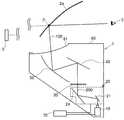
- FIG. 1shows an outline of a head-up display device (hereinafter referred to as a HUD device) 1 according to the present embodiment.
- the HUD device 1is typically installed in a dashboard of the host vehicle 2, but a part or all of the HUD device 1 may be arranged on a tash board.
- FIG. 2is a schematic cross-sectional view showing the configuration of the HUD device 1.
- the HUD device 1includes a projection unit 10, an optical axis adjustment unit 20, a transmission screen 30, a folding mirror 40, a concave mirror 50, a housing 60 that stores these, a HUD And a control unit 70 that performs electrical control of the device 1.
- the image light 100 emitted from the HUD device 1is projected onto a projection point P of a windshield (an example of a transmission / reflection surface) 2a and reflected by the windshield 2a, so that the front of the windshield 2a (for example, 10 to 20 m ahead) ) To make the virtual image V visible at an arbitrary position.
- a windshieldan example of a transmission / reflection surface
- FIG. 3is a diagram for explaining a specific configuration of the projection unit 10 and the optical axis adjustment unit 20 and an optical path of the projection light 200.
- the projection unit 10 in FIG. 3includes a light source 11 that emits illumination light 300, a light source mirror 12, a prism 13, a reflective display 14, and a projection lens 15, and displays a display image on a transmissive screen 30.
- the projection light 200 for forming(not shown) is emitted toward the optical axis adjustment unit 20.
- the display image formed on the transmissive screen 30may be generally called a real image.
- the light source 11 in FIG. 3has, for example, a plurality of LEDs that can output red, blue, and green light, respectively, and is illuminated with a desired color, light intensity, and timing under the control of the control unit 70 described later.
- Light 300is emitted.
- the projection unit 10 in this embodimentemploys a field sequential color driving method, and the light source 11 of each color emits the illumination light 300 in a time-sharing manner.
- the light source mirror 12 of FIG. 3is formed by forming a reflective film on the surface of a base material made of a synthetic resin material by means such as vapor deposition, and the reflective display 14 by reflecting the illumination light 300 from the light source 11. Is incident at an appropriate angle.
- the reflective display 3is disposed between the light source mirror 12 and the reflective display 14, and has an inclined surface 13a inclined at a predetermined angle with respect to the optical axis of the illumination light 300 incident from the light source mirror 12.
- the illumination light 300 from the light source mirror 12 incident on the inclined surface 13ais transmitted through the inclined surface 13a, incident on the reflective display 14, and the projection light 200 emitted from the reflective display 14 is again the prism 13. And is reflected toward the projection lens 15 by the inclined surface 13a.
- the control unit 70Under the control of the control unit 70, the light is converted into projection light 200 for displaying the virtual image V and reflected toward the prism 13.
- DMDDigital Micromirror Device
- LCoSLiquid Crystal On Silicon
- the projection lens 3is formed of, for example, a convex lens, and expands the projection light 200 incident from the prism 13 and emits it in the direction of the optical axis adjustment unit 20.
- the projection lens 15images the projection light 200 on the transmission screen 30.
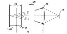
- the projection image distance 151 of the projection lens 15 in FIG. 3will be described with reference to FIG.
- the projection lens 15generates the display image in which the projection light 200 emitted from the reflective display 14 is imaged at a position away from the projection lens 15 by a predetermined projection image distance 151, and before and after the projection image distance 151.
- the display image substantially in focus by the projection light 200can be generated within the projection image plane depth 152 that is a predetermined range.
- the optical axis adjusting unit 20 described lateris disposed between the projection lens 15 and the transmissive screen 30, and adjusts the angle of the optical axis of the projection light 200 incident on the transmissive screen 30.
- the optical path length of the projection light 200 up to the axis adjustment unit 20is changed.
- the optical path length of the projection light 200 from the projection lens 15 to the optical axis adjustment unit 20is also referred to as a projection distance.
- the optical axis adjustment unit 20adjusts the angle of the optical axis of the projection light 200 within the range in which the projection distance of the projection light 200 falls within the projection image plane depth 152 of the projection lens 15, so The display image that is substantially in focus can be generated.
- the projection image plane depth 152includes a front projection image plane depth 152a on the projection lens 15 side from the projection image distance 151 and a rear projection image plane depth 152b on the opposite side of the projection lens 15 from the projection image distance 151.
- the projection image plane depth 152has a range of about 3.319 mm, for example, where the front projection image plane depth 152a is 1.641 mm and the rear projection image plane depth is 1.678 mm.
- the projected image distance 151 and the projected image plane depth 152may be referred to as a focal length and a focal depth, respectively.
- the optical axis adjustment unit 20 in FIG. 3receives the projection light 200 emitted from the projection unit 10, adjusts the optical axis of the projection light 200, and projects it onto the transmissive screen 30.
- the optical axis adjustment unit 20includes a first reflection unit 21 that receives and reflects the projection light 200 from the projection unit 10, and a first rotation unit that rotates the first reflection unit 21 about the first rotation shaft 23.
- An actuator 22, a second reflecting portion 24that receives the projection light 200 reflected by the first reflecting portion 21 and reflects it toward the transmissive screen 30, and the second reflecting portion 24 passes through the second rotating shaft 26.
- a second actuator 25that rotates about the center.
- the first actuator 22 shown in FIG. 3is, for example, a plane mirror, and reflects the projection light 200 emitted from the projection unit 10 toward the second reflection unit 24.
- the first actuator 22 shown in FIG. 3is formed of, for example, a stepping motor, and a gear is provided on the rotation shaft thereof.
- the first actuator 22is disposed in the housing 60, and the gear is meshed with the gear of the first reflecting portion 21.
- the 1st reflection part 21may be formed in a concave surface, a convex surface, and a free-form surface shape.
- the second reflection unit 24 illustrated in FIG. 3is, for example, a plane mirror, and reflects the projection light 200 reflected by the first reflection unit 21 toward the transmissive screen 30.
- the second reflection unit 24 illustrated in FIG. 3is formed of, for example, a stepping motor, and a gear is provided on the rotation shaft thereof.
- the second actuator 25is disposed in the housing 60, and the gear is meshed with the gear of the second reflecting portion 24. Thereby, with the rotational drive of the second actuator 25, the inclination angle of the second reflecting portion 24 is adjusted around the second rotation shaft 26, and the reflection direction of the projection light 200 can be adjusted.
- the first rotation shaft 23 that is the rotation center of the first reflection portion 21 and the second rotation shaft 26 that is the rotation center of the second reflection portion 24are arranged in parallel in the same direction.
- the optical axis adjustment unit 20is arranged so that the projection light 200 from the projection unit 10 is incident on the first rotation shaft 23 (second rotation shaft 26) perpendicularly. Thereby, even when the first reflecting portion 21 and the second reflecting portion 24 are rotated by “optical axis adjustment processing” to be described later, the first reflecting portion 21 always reflects from the projecting portion 10 to the second reflecting portion 24.
- the optical path of the projection light 200 and the optical path of the projection light 200 from the first reflecting part 21 reflected by the second reflecting part 24 to the transmissive screen 30pass on the same plane. That is, the optical path change of the projection light 200 due to the rotation of the first reflection unit 21 and the second reflection unit 24 is simplified, and the arrangement and mechanism of the optical axis adjustment unit 20 can be simplified.
- the 2nd reflection part 24may be formed in a concave surface, a convex surface, and a free-form surface shape.
- the optical axis adjustment unit 20 in FIG. 3adjusts the angles of the first reflection unit 21 and the second reflection unit 24 in association with each other, thereby allowing the incidence of the optical axis of the projection light 200 incident on the transmissive screen 30.
- the anglecan be adjusted.
- the “optical axis adjustment process” performed by the optical axis adjustment unit 20 for adjusting the angle of the optical axis of the projection light 200will be described in detail later.
- the HUD device 1 of the present inventioncan adjust the optical axis direction of the image light 100 emitted from the transmission screen 30 by the optical axis adjustment unit 20. That is, since the HUD device 1 of the present invention can adjust the position of the light distribution area E where the image light 100 is distributed, the image light 100 (light distribution area E) is efficiently applied to the observer's viewpoint position. Can be directed.
- the folding mirror (relay optical system) 40 shown in FIG. 2is a projection in which a reflective film is formed on the surface of a base material made of, for example, a synthetic resin material by means of vapor deposition or the like.
- the light 200is reflected toward a concave mirror 50 described later.
- the concave mirror (relay optical system) 50 in FIG. 2is obtained by forming a reflective film on the surface of a base material made of, for example, a synthetic resin material by means such as vapor deposition, and the curvature of the concave mirror 50 is a concave free-form surface.
- a base materialmade of, for example, a synthetic resin material by means such as vapor deposition
- the detailed surface shapeincludes the positional relationship among the transmission screen 30, the folding mirror 40, the windshield 2a, the movement range (eye box) of the observer's viewpoint, the curvature of the windshield 2a, and the required virtual image. It is calculated by optical design software based on the imaging distance of V and the angle of view of the HUD device 1 visually recognized by the observer.
- the concave mirror 50can be designed by optical design software so that the distortion of the virtual image V is minimized under the constraint that the position of the virtual image V does not change even if the viewpoint position of the observer moves.
- the projection light 200 reflected by the folding mirror 40is magnified and reflected toward the windshield 2a.
- the relay optical system that directs the image light 100 from the transmissive screen 30 toward the light distribution area Eis not limited to the reflective relay optical system such as the folding mirror 40 and the concave mirror 50, but a refractive relay optical system such as a lens. It may be a system.
- the housing 60 in FIG. 2is a substantially box-shaped member made of a metal material such as aluminum, and is provided with various mounting shapes (not shown) therein.
- the optical axis adjustment unit 20, the transmissive screen 30, and the folding mirror 40are held in a predetermined positional relationship.
- the inner surface of the housing 60is painted, for example, in black, so that stray light caused by the outside of the HUD device 1 or the projection unit 10 is hardly generated.
- a light transmitting portion 61 formed of a transparent resin material that transmits the image light 100 reflected by the concave mirror 50is provided on the upper surface of the housing 60.
- the control unit 70includes a processing unit 71 having one or a plurality of microprocessors, microcontrollers, ASICs, FPGAs, arbitrary other ICs, etc., a flash that is a ROM, an EEPROM, and a nonvolatile memory.
- a storage unit 72having one or a plurality of memories capable of storing a program such as a memory and data, and an input / output unit 73 connected to a network unit 80 to be described later are provided.
- the control unit 70is mounted on a printed circuit board (not shown) or the like that is provided inside or partially or entirely outside the housing 60.
- the network unit 80is, for example, a CAN (Controller Area Network) or the like, and allows the control unit 70 (input / output unit 73) to send and receive signals to a vehicle-side viewpoint position detection unit 91 and an operation input unit 92, which will be described later. Connecting.
- CANController Area Network
- the viewpoint position detection unit 91 in FIG. 5detects an observer's viewpoint position (at least the vertical position of the viewpoint in the vertical direction).
- an infrared camera(not shown) that images the observer;
- a viewpoint image analysis unit(not shown) for analyzing imaging data acquired by the infrared camera.
- the infrared cameracaptures the eyes of the observer, and the viewpoint image of the observer is obtained by performing image analysis on the imaging data acquired by the viewpoint image analysis unit with the infrared camera using a known image processing, pattern matching method, or the like.
- the positionis analyzed, and information on the viewpoint position of the observer (viewpoint position information B) is output to the control unit 70.
- the controller 70drives the first actuator 22 and the second actuator 25 to rotate the first reflector 21 and the second reflector 24 as described later. Move.
- the direction of the image light 100may be adjusted by the observer operating the operation input unit 92 so as to match his or her viewpoint position.
- the control unit 70inputs operation information from the operation input unit 92 via the input / output unit 73, and drives the first actuator 22 and the second actuator 25 based on this operation information as described later. Then, the first reflecting portion 21 and the second reflecting portion 24 are rotated.
- the input / output unit 73 in FIG. 5inputs the viewpoint position information B from the viewpoint position detection unit 91 and the operation information from the operation input unit 92 via the network unit 80.
- the processing unit 71reads out and executes a program for optical axis adjustment processing from the storage unit 72 based on the viewpoint position information B input from the input / output unit 73 or the operation information.
- the storage unit 72stores in advance table data in which the viewpoint position information B or the operation information is associated with the control data of the first actuator 22 and the second actuator 25.
- the processing unit 71uses the table data stored in the storage unit 72 to read the viewpoint position information B input from the input / output unit 73 or the control data associated with the operation information, and the first actuator 22 And the second actuator 25 is driven.
- the input / output unit 73 in this embodimentalso has functions as viewpoint position information acquisition means and operation information acquisition means described in the claims.
- the processing unit 71distorts the image generated by the reflective display 14 in advance and emits it as the projection light 200, whereby the angles of the first reflecting unit 21 and the second reflecting unit 24, the curvature of the concave mirror 50, It is possible to cancel or reduce image distortion caused by the curvature of the windshield 2a (reflection / transmission surface), the viewpoint position of the observer, and the like.
- the “optical axis adjustment process” in this embodimentwill be described with reference to FIGS.
- FIG. 6is a flowchart of the optical axis adjustment process of the present embodiment.
- the processing unit 71inputs current viewpoint position information B regarding the viewpoint position (including at least height) of the observer from the viewpoint position detection unit 91 via the input / output unit 73.
- the processing unit 71proceeds to step S2.
- step S2the processing unit 71 reads the previous (immediate) viewpoint position information A stored in the storage unit 72, and in step S3, the difference between the past viewpoint position information A and the current viewpoint position information B. C is calculated.
- step S4the processing unit 71 determines whether or not the absolute value of the difference C is greater than a predetermined threshold value x (
- a predetermined threshold value x
- step S5the processing unit 71 reads control data (correction values) of the first actuator 22 and the second actuator 25 corresponding to the current viewpoint position information B from the storage unit 72, and then in step S6, the control data is read. Output to the first actuator 22 and the second actuator 25.
- the control data of the first actuator 22 and the second actuator 25is stored in the storage unit 72 as table data associated with the viewpoint position information, for example.
- the first actuator 22is rotationally driven based on the input control data to adjust the tilt angle of the first reflecting portion 21, and the second actuator 25 is rotationally driven based on the input control data. Then, the inclination angle of the second reflecting portion 24 is adjusted.
- step S7the processing unit 71 stores the current viewpoint position information B as past viewpoint position information A in the general-purpose memory, and updates the past viewpoint position information A.
- the processing unit 71repeatedly executes the above-described control until the power is turned off, thereby operating the first actuator 22 and the second actuator 25 according to the latest viewpoint position information B of the observer to perform the first reflection.
- the projection angle of the image light 100can be adjusted according to the height of the observer's viewpoint position by adjusting the inclination angle of the part 21 and the inclination angle of the second reflection part 24.
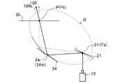
- FIG. 7Ais a diagram illustrating a state of the optical axis adjustment unit 20 when the image light 100a is directed to a relatively high viewpoint position 3a with respect to the reference viewpoint position 3.
- the processing unit 71executes the control method described above to control the first actuator 22 and the second actuator 25 in accordance with the latest viewpoint position information B input.
- the first actuator 22By rotating the first actuator 22 to rotate the first reflecting portion 21 in the clockwise direction in FIG. 7A and adjusting the tilt angle of the first reflecting portion 21 in a more rising direction, the projection light 200 received from the projection portion 10 is obtained. Is adjusted to the direction of reference numeral 200a shown in FIG. 7A.
- the second actuator 25to rotate the second reflecting portion 24 in the clockwise direction in FIG.
- the received projection light 200 ais reflected so as to pass through a predetermined point D on the transmissive screen 30.
- the transmissive screen 30receives the projection light 200a reflected from the second reflection unit 24 on the back surface, and emits image light 100a along the projection light 200a.
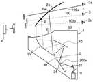
- FIG. 7Bshows the entire HUD device 1 when the image light 100a is directed to the viewpoint position 3a that is relatively higher than the reference viewpoint position 3 described in FIG. 7A.
- the image light 100a whose angle has been adjusted by the optical axis adjustment unit 20 in FIG. 7Ais viewed at a projection point Pa located above the projection point P of the image light 100 toward the reference viewpoint position 3 as shown in FIG. 7B. Reflected toward position 3a.
- the image light 100a directed to the observer's viewpoint position 3apasses through a predetermined point D on the transmission screen 30 in the same manner as the image lights 100 and 100b directed to the viewpoint positions 3 and 3b of FIG. 7B.
- the imaging position of the virtual image V visually recognized from the relatively high viewpoint position 3asubstantially matches the imaging position of the virtual image V visually recognized at the standard viewpoint position 3 and the relatively low point position 3b.
- the optical axis adjustment process of the optical axis adjustment unit 20can efficiently direct the image light 100 emitted from the transmission screen 30 to the relatively high viewpoint position 3a.
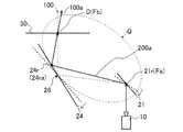
- FIG. 8Ais a diagram illustrating a state of the optical axis adjustment unit 20 when the image light 100b is directed to the viewpoint position 3b that is lower than the reference viewpoint position 3.
- the processing unit 71executes the control method described above to control the first actuator 22 and the second actuator 25 in accordance with the latest viewpoint position information B input.
- the first actuator 22By rotating the first actuator 22 to rotate the first reflecting portion 21 counterclockwise in FIG. 8A and adjusting the tilt angle of the first reflecting portion 21 in a more tilted direction, the projection received from the projection portion 10 is received.
- the reflection direction of the light 200is adjusted to the direction of the reference numeral 200b illustrated in FIG. 8A.
- the second reflecting portion 24is rotated counterclockwise in FIG.
- the projection light 200 b received from 21is reflected so as to pass through a predetermined point D on the transmission screen 30.
- the transmissive screen 30receives the projection light 200b reflected from the second reflection unit 24 on the back surface, and emits image light 100b along the projection light 200b.
- FIG. 8Bshows the entire HUD device 1 when the image light 100b is directed to the viewpoint position 3b that is relatively lower than the reference viewpoint position 3 described in FIG. 8A.
- the image light 100b whose angle has been adjusted by the optical axis adjustment unit 20 in FIG. 8Ahas a viewpoint at a projection point Pb located below the projection point P of the image light 100 toward the reference viewpoint position 3 as shown in FIG. 8B. Reflected toward position 3b.
- the image light 100b directed to the observer's viewpoint position 3bpasses through a predetermined point D on the transmission screen 30 in the same manner as the image lights 100 and 100a directed to the viewpoint positions 3 and 3a of FIG. 8B.
- the imaging position of the virtual image V visually recognized from the relatively low viewpoint position 3bsubstantially coincides with the imaging position of the virtual image V visually recognized at the standard viewpoint position 3 and the relatively high point position 3a.
- the optical axis adjustment processing of the optical axis adjustment unit 20can efficiently direct the image light 100 emitted from the transmission screen 30 to the relatively low viewpoint position 3b.
- the first reflection unit 21 and the transmission screen 30are respectively disposed at or near the focal points Fa and Fb of a predetermined ellipse Q as shown in FIGS. 7A and 8A, for example.
- the center point 21r on the reflection surface of the first reflection unit 21is disposed at one focal point Fa of the ellipse Q
- the center point of the transmissive screen 30is disposed at the other focal point Fb.
- the second reflection unit 24transmits the projection light 200 reflected by the first reflection unit 21 at the reflection position 24r (24ra, 24rb) near the locus of the ellipse Q indicated by the dotted line in FIGS. 7A and 8A. Reflects toward a predetermined point D on 30.
- the sum of the distance from one focal point Fa to the reflection position 24r and the distance from the reflection position 24r to the other focal point Fbis equal to the reflection position 24r if the reflection position 24r is on the locus of the ellipse Q. It is constant regardless of the position. In other words, if the light (projection light 200) from one focal point Fa (first reflection portion 21) is reflected on the locus of the ellipse Q toward the other focal point Fb (transmission screen 30), the one focal point Fa.
- the optical path length of the light (projection light 200) from the (first reflection portion 21) to the other focal point Fb (transmission type screen 30)can always be constant.
- the second reflecting portion 24since the second reflecting portion 24 rotates around the second rotating shaft 26, the second reflecting portion 24 reflects when the reflecting point 24r is arranged on the locus of the ellipse Q.
- the projection light 200does not pass through the predetermined point D on the transmissive screen 30. That is, when the angle of the second reflecting portion 24 is adjusted so that the reflection point 24 r of the second reflecting portion 24 is arranged on the locus of the predetermined ellipse Q, the display image formed on the transmissive screen 30 The position will shift.
- the transmissive screen 30is prevented from protruding from the transmissive screen 30. It is necessary to increase the size in advance.
- the second reflecting portion 24 of the present embodimenthas a position that is not on the locus of the ellipse Q so as to reflect the projection light 200 reflected by the first reflecting portion 21 toward the predetermined point D on the transmissive screen 30.
- the reflection positionis 24r (24ra, 24rb).
- the reflection point 24r of the second reflection unit 24is not arranged on the locus of the ellipse Q, the optical path of the projection light 200 from the first reflection unit 21 to the transmission screen 30 is performed by the optical axis adjustment process.
- the lengthis not always constant, the projection distance that is changed by the optical axis adjustment process is suppressed within the range of the projection image plane depth of the projection lens 15 so that the transmission screen 30 can be regarded as being in focus.
- a display imagecan be generated.
- the HUD device 1 described abovecauses the observer to visually recognize the virtual image V, and the projection unit 10 that emits the projection light 200 and the first reflection unit 21 that reflects the projection light 200 emitted from the projection unit 10.
- a first actuator 22that rotates the first reflecting portion 21, a second reflecting portion 24 that reflects the projection light 200 reflected by the first reflecting portion 21, and a second actuator that rotates the second reflecting portion 24.
- a control unit 70that controls the first actuator 22 and the second actuator 25, a transmission screen 30 that transmits and diffuses the projection light 200 reflected by the second reflection unit 24, and an image emitted from the transmission screen 30 Even when the light 100 is reflected toward the windshield 2a (transmission reflection surface) and the height of the viewpoint of the observer changes within a predetermined range, And a concave mirror 50 having a concave curved surface that suppresses this, and the control unit 70 drives the first actuator 22 and the second actuator 25 to adjust the optical axis of the projection light 200 incident on the transmissive screen 30. Adjust the angle. Accordingly, it is possible to direct the direction of the image light 100 emitted from the transmission screen 30 to the viewpoint position of the observer by a simple method of rotating the first reflecting portion 21 and the second reflecting portion 24.
- the optical axis adjustment unit 20sets the angle of the projection light 200 incident on the transmissive screen 30 to direct the image light 100 to the normally used viewpoint height range (viewpoint positions 3a to 3b) within a predetermined angle range.
- the projection distance from the projection unit 10 to the transmission screen 30 of the projection light 200 adjusted within the angle rangeis within the projection image plane depth of the projection lens 15, so that the optical axis adjustment process is performed. Even in such a case, the display image that can be regarded as being in focus can be formed on the transmissive screen 30.
- the optical axis adjustment unit 20also projects the projection light 200 into the first projection light 200 along the first optical axis and the second projection along the second optical axis, which are incident on the transmission screen 30 at different angles.
- the light 200acan be adjusted at least to the third projection light 200b along the third optical axis, and the first, second, and third image lights 200, 200a, and 200b are transmitted on the transmission screen 30.
- the predetermined point Dis arranged on the transmission screen 30, but it may not be on the transmission screen 30. Specifically, the position of the transmission screen 30 may be shifted from the position illustrated in FIG. 7B to the folding mirror 40 side or the projection unit 10 side.
- the concave mirror 50has a concave curved surface that suppresses a shift in the position where the virtual image V is viewed with respect to the real scene even when the height of the observer's viewpoint changes within a predetermined range.
- the 2nd reflection part 24only rotated centering on the 2nd rotation axis
- the projection light 200 incident from the first reflection unit 21can be directed to the predetermined point D while keeping the optical path length from the projection unit 10 to the transmission screen 30 constant.
- the 1st reflection part 21 and the 2nd reflection part 24were each rotated with the separate actuator, the 1st reflection part 21 and the 2nd reflection part 24 are carried out by the common actuator which is not shown in figure. May be rotated.
- the 1st reflection part 21 and the 2nd reflection part 24are different by changing gear ratios, such as a gearwheel which transmits motive power to the 1st reflection part 21 and the 2nd reflection part 24 from the said common actuator, respectively. As the actuator is driven, it rotates at a predetermined rotation ratio.
- the control unit 70corrects the distortion of the virtual image V according to the operating state of the first actuator 22 and / or the second actuator 25, that is, the incident angle of the projection light 200 on the transmission screen 30.
- the parametermay be changed.
- This correction parameteris a parameter for distorting and displaying the display image in advance in the direction opposite to the distortion in the windshield 2a in order to suppress the distortion of the virtual image V projected on the windshield 2a.
- a plurality of correction parametersare stored in the storage unit 72 as a data table in association with the control data of the first actuator 22 and / or the second actuator 25, and the processing unit 71 is determined by the control method described above.
- the correction parameteris determined according to the control data of the actuator 22 and / or the second actuator 25 and is output to the projection unit 10.
- the reflection / transmission surface on which the projection light 200 is projectedis not limited to the windshield 2 a of the host vehicle 2.
- the reflection / transmission surface onto which the projection light 200 is projectedmay be, for example, a dedicated combiner member.
- the projection unit 10may have a function of adjusting the projection image distance 151 by adjusting the position of the projection lens 15, for example.
- the present inventioncan be applied as a head-up display device mounted on a moving body such as a vehicle.
Landscapes
- Engineering & Computer Science (AREA)
- Physics & Mathematics (AREA)
- General Physics & Mathematics (AREA)
- Transportation (AREA)
- Mechanical Engineering (AREA)
- Chemical & Material Sciences (AREA)
- Combustion & Propulsion (AREA)
- Optics & Photonics (AREA)
- Theoretical Computer Science (AREA)
- Computer Hardware Design (AREA)
- General Engineering & Computer Science (AREA)
- Human Computer Interaction (AREA)
- Instrument Panels (AREA)
- Transforming Electric Information Into Light Information (AREA)
- Devices For Indicating Variable Information By Combining Individual Elements (AREA)
Abstract
Description
Translated fromJapanese本発明は、実景に画像を重ねて視認させるヘッドアップディスプレイ装置に関する。The present invention relates to a head-up display device that superimposes an image on a real scene for visual recognition.
ヘッドアップディスプレイ装置は、自車両前方の実景に虚像を重ねて表示することで、実景に情報などを付加した拡張現実(AR:Augmented Reality)を生成し、車両を運転する観察者の視線移動を極力抑えつつ、所望の情報を的確に観察者に対して提供することで、安全で快適な車両運行に寄与するものである。The head-up display device generates an augmented reality (AR: Augmented Reality) with information added to the real scene by displaying a virtual image superimposed on the real scene ahead of the host vehicle, and moves the line of sight of the observer driving the vehicle. While providing as much information as possible to the observer while suppressing as much as possible, it contributes to safe and comfortable vehicle operation.
このような観察者に虚像を視認させるものとして、例えば、特許文献1には、所定の投影位置に光束を投影し、虚像を観察者に視認させる投影部を備え、観察者の視点位置を検出し、この検出した視点位置に基づいて可動式ミラーを回動させることで、投影部が出射する光束を観察者の視点位置に向かわせる画像表示装置が開示されている。For example,
次に、例えば特許文献2には、表示器と反射部とを円弧に沿って移動させながら角度を調整することで、表示器から出射される画像光を観察者の視点位置に向け、表示器からの画像光を効率よく観察者に視認させる表示装置が開示されている。Next, for example, in
特許文献1のように、観察者の視点位置に合わせて可動式ミラーを回動させて光束の投影位置を調整する場合、例えば図10に示すように、画像光Nを出射する表示器101と、表示器101からの画像光Nを反射する反射部102と、反射部102が反射した画像光Nを透過反射面200に反射する凹面反射部(可動式ミラー)103と、を備え、凹面反射部103を回動させることで、画像光Nを投影する位置を調整する。When the projection position of the light beam is adjusted by rotating the movable mirror in accordance with the observer's viewpoint position as in
図10を参照すると、視点の高さが異なる観察者に向かうそれぞれの画像光Nは、表示器101の表示面101aからそれぞれ異なる方向へ出射された光である。視点の高さが違った場合でも視認される虚像の輝度が変化しないようにするには、表示器101が出射する画像光Nの配光特性を広い範囲で一定にする必要がある。従って、表示器101から出射される画像光Nの配光角(拡散角)を大きくする(指向性を低くする)必要があり、表示器101の効率が低下してしまう。Referring to FIG. 10, each image light N directed toward an observer having a different viewpoint height is light emitted in a different direction from the display surface 101 a of the
また、特許文献2に開示されているように、画像光を観察者の視点位置に向けるため、電子機器である表示器を円弧に沿って移動させるには、複雑で大掛かりな移動機構などが必要であった。Further, as disclosed in
したがって、本発明は、上記実情を鑑みてなされたものであり、簡易な構成で、観察者に効率よく画像光を向けることができるヘッドアップディスプレイ装置を提供することを目的とする。Therefore, the present invention has been made in view of the above circumstances, and an object thereof is to provide a head-up display device that can direct image light efficiently to an observer with a simple configuration.
上記目的を達成するため、本発明に係るヘッドアップディスプレイ装置は、画像光を透過反射面に投影することで、前記透過反射面を介した実景とともに前記画像光に基づく虚像を視認させるヘッドアップディスプレイ装置において、表示画像を示す投影光を出射する投影部と、前記投影光を透過拡散した前記画像光を前記透過反射面側に向ける透過型スクリーンと、前記投影部と前記透過型スクリーンとの間に配置され、前記投影部が出射した前記投影光を反射する第一反射部と、前記第一反射部が反射した前記投影光を反射する第二反射部と、前記第一反射部と前記第二反射部とを回動させるアクチュエータと、を有し、前記透過型スクリーンに入射する前記投影光の光軸の角度を調整する光軸調整部と、を備える。In order to achieve the above object, a head-up display device according to the present invention projects an image light onto a transmission / reflection surface so that a virtual image based on the image light can be visually recognized together with a real scene through the transmission / reflection surface. In the apparatus, a projection unit that emits projection light indicating a display image, a transmission screen that directs the image light that is transmitted and diffused through the projection light toward the transmission / reflection surface side, and between the projection unit and the transmission screen A first reflection part that reflects the projection light emitted from the projection part, a second reflection part that reflects the projection light reflected by the first reflection part, the first reflection part, and the first reflection part. And an optical axis adjustment unit that adjusts the angle of the optical axis of the projection light incident on the transmission screen.
本発明のヘッドアップディスプレイ装置によれば、簡易な構成で、観察者に効率よく画像光を向けることができる。According to the head-up display device of the present invention, image light can be efficiently directed to an observer with a simple configuration.
本発明の実施形態について、図面を参照して説明する。なお、以下に説明する画像光100,投影光200,照明光300などの光束は、あらゆる方向に無数に存在するが、図面の理解を容易にするため、各光束の中心となる光軸のみ図示するものとする。Embodiments of the present invention will be described with reference to the drawings. Note that there are an infinite number of light beams such as the
図1は、本実施形態に係るヘッドアップディスプレイ装置(以下、HUD装置と記載)1の概略を示す。図1に示すように、HUD装置1は、典型的には自車両2のダッシュボード内に設置されるが、HUD装置1の一部または全部がタッシュボード上に配置されてもよい。FIG. 1 shows an outline of a head-up display device (hereinafter referred to as a HUD device) 1 according to the present embodiment. As shown in FIG. 1, the
図2は、HUD装置1の構成を示す概略断面図である。
図2に示すように、HUD装置1は、投影部10と、光軸調整部20と、透過型スクリーン30と、折り返しミラー40と、凹面ミラー50と、これらを収納する筐体60と、HUD装置1の電気的な制御を行う制御部70と、を備える。HUD装置1が出射する画像光100は、ウインドシールド(透過反射面の一例)2aの投影点Pに投影され、ウインドシールド2aで反射されることで、ウインドシールド2aの前方(例えば10~20m前方)の任意の位置に虚像Vを視認させる。FIG. 2 is a schematic cross-sectional view showing the configuration of the
As shown in FIG. 2, the
(投影部10)
図3は、投影部10及び光軸調整部20の具体的な構成と、投影光200の光路を説明するための図である。
図3の投影部10は、照明光300を出射する光源11と、光源ミラー12と、プリズム13と、反射型表示器14と、投射レンズ15と、を備え、透過型スクリーン30上に表示画像(図示しない)を形成するための投影光200を光軸調整部20に向けて出射するものである。なお、透過型スクリーン30に形成される前記表示画像は、一般的に実像と言われてもよい。(Projector 10)
FIG. 3 is a diagram for explaining a specific configuration of the
The
図3の光源11は、例えば、赤色,青色,緑色の光をそれぞれ出力可能な複数のLEDを有し、後述する制御部70からの制御のもと、所望の色,光強度,タイミングで照明光300を出射する。また、本実施形態における投影部10は、フィールドシーケンシャルカラー(Field Sequential Color)駆動方式を採用しており、各色の光源11が時分割的に照明光300を出射する。The
図3の光源ミラー12は、例えば、合成樹脂材料からなる基材の表面に、蒸着等の手段により反射膜を形成したものであり、光源11からの照明光300を反射によって反射型表示器14へ適正な角度で入射させるものである。The
図3のプリズム13は、光源ミラー12と反射型表示器14との間に配置され、光源ミラー12から入射する照明光300の光軸に対して所定の角度で傾いた傾斜面13aを有する。傾斜面13aに入射した光源ミラー12からの照明光300は、傾斜面13aを透過し、反射型表示器14に入射し、そして、反射型表示器14から出射した投影光200は、再びプリズム13に入射し、傾斜面13aにより投射レンズ15の方向へ反射する。3 is disposed between the
図3の反射型表示器14は、例えば、DMD(Digital Micromirror Device)やLCoS(登録商標:Liquid Crystal On Silicon)などの反射型の表示デバイスであり、プリズム13から入射した照明光300を、後述する制御部70の制御のもと、虚像Vを表示するための投影光200に変換してプリズム13に向けて反射する。3 is a reflective display device such as DMD (Digital Micromirror Device) or LCoS (registered trademark: Liquid Crystal On Silicon), and the
図3の投射レンズ15は、例えば、凸レンズなどで形成され、プリズム13から入射する投影光200を拡大して、光軸調整部20の方向へ出射する。投射レンズ15は、透過型スクリーン30上に投影光200を結像させる。3 is formed of, for example, a convex lens, and expands the
図4を用いて、図3の投射レンズ15の投影像距離151について説明する。投射レンズ15は、投射レンズ15から所定の投影像距離151だけ離れた位置で反射型表示器14から出射された投影光200を結像した前記表示画像を生成し、投影像距離151の前後の所定の範囲である投影像面深度152内で投影光200による概ねピントのあった前記表示画像を生成することができる。後述する光軸調整部20は、投射レンズ15と透過型スクリーン30との間に配置され、透過型スクリーン30に入射する投影光200の光軸の角度を調整する際に、投射レンズ15から光軸調整部20までの投影光200の光路長を変化させる。以下、投射レンズ15から光軸調整部20までの投影光200の光路長を投射距離とも呼ぶ。光軸調整部20は、投影光200の前記投射距離が投射レンズ15の投影像面深度152内に収まる範囲内で投影光200の光軸の角度を調整することで、透過型スクリーン30上に概ねピントのあった前記表示画像を生成することができる。なお、投影像面深度152は、投影像距離151から投射レンズ15側の前方投影像面深度152aと、投影像距離151から投射レンズ15とは反対側の後方投影像面深度152bとからなる。投影像面深度152は、具体的に例えば、前方投影像面深度152aが1.641mm、後方投影像面深度が1.678mmからなる3.319mm程の範囲を有する。なお、投影像距離151,投影像面深度152は、それぞれ、焦点距離,焦点深度と呼ばれてもよい。The
(光軸調整部20)
図3の光軸調整部20は、投影部10が出射した投影光200を受光し、この投影光200の光軸を調整して、透過型スクリーン30に向けて投影する。光軸調整部20は、投影部10からの投影光200を入射して反射する第一反射部21と、この第一反射部21を第一の回動軸23を中心に回動させる第一アクチュエータ22と、第一反射部21が反射した投影光200を入射して透過型スクリーン30に向けて反射する第二反射部24と、この第二反射部24を第二の回動軸26を中心に回動させる第二アクチュエータ25と、を有する。(Optical axis adjustment unit 20)
The optical
図3の第一反射部21は、例えば、平面ミラーであり、投影部10が出射した投影光200を、第二反射部24に向けて反射させる。図3の第一アクチュエータ22は、例えばステッピングモータからなり、その回転軸に歯車が設けられている。第一アクチュエータ22は、筐体60内に配置され、前記歯車は第一反射部21の歯車と噛み合わされる。これにより、第一アクチュエータ22の回転駆動に伴って、第一反射部21の傾斜角が第一の回動軸23を中心に調整され、投影光200の反射方向を調整することができる。なお、第一反射部21は、凹面、凸面、自由曲面形状で形成されてもよい。3 is, for example, a plane mirror, and reflects the
図3の第二反射部24は、例えば、平面ミラーであり、第一反射部21が反射した投影光200を、透過型スクリーン30に向けて反射させる。図3の第二アクチュエータ25は、例えばステッピングモータからなり、その回転軸に歯車が設けられている。第二アクチュエータ25は、筐体60内に配置され、前記歯車は第二反射部24の歯車と噛み合わされる。これにより、第二アクチュエータ25の回転駆動に伴って、第二反射部24の傾斜角が第二の回動軸26を中心に調整され、投影光200の反射方向を調整することができる。なお、第一反射部21の回転中心となる第一の回動軸23と、第二反射部24の回転中心となる第二の回動軸26とは、同じ向きで平行に配置される。また、光軸調整部20は、投影部10からの投影光200を、第一の回動軸23(第二の回動軸26)に垂直に入射するように配置される。これによって、第一反射部21及び第二反射部24が後述する『光軸調整処理』によりそれぞれ回転した場合でも、常に、第一反射部21が反射する投影部10から第二反射部24までの投影光200の光路と、第二反射部24が反射する第一反射部21から透過型スクリーン30までの投影光200の光路とは、同一平面上を通る。すなわち、第一反射部21及び第二反射部24が回動による投影光200の光路変化が単純化され、光軸調整部20の配置や機構を簡素化することができる。なお、第二反射部24は、凹面、凸面、自由曲面形状で形成されてもよい。3 is, for example, a plane mirror, and reflects the
すなわち、図3の光軸調整部20は、第一反射部21及び第二反射部24それぞれの角度を連動して調整することで、透過型スクリーン30に入射する投影光200の光軸の入射角度を調整することができる。この光軸調整部20が行う投影光200の光軸の角度を調整する『光軸調整処理』については、後で詳述する。In other words, the optical
図3の透過型スクリーン30は、例えば、ホログラフィックディフューザ、マイクロレンズアレイ、拡散板等によって構成され、光軸調整部20(第二反射部24)からの投影光200を背面で受光し、図1の配光エリアEに向けて透過拡散させた画像光100を出射するものである。透過型スクリーン30は、投影光200を入射して拡散した光を折り返しミラー40に向かわせる。透過型スクリーン30は、観察者の視点位置が配光エリアE内であれば、視認される虚像Vの輝度が略均一に視認されるように画像光100を配向する。本発明のHUD装置1は、光軸調整部20により透過型スクリーン30から出射される画像光100の光軸方向を調整することができる。すなわち、本発明のHUD装置1は、画像光100が配光される配光エリアEの位置を調整することができるため、観察者の視点位置に効率よく画像光100(配光エリアE)を向けることができる。3 includes, for example, a holographic diffuser, a microlens array, a diffusing plate, and the like, and receives projection light 200 from the optical axis adjustment unit 20 (second reflection unit 24) on the back surface. The
図2の折り返しミラー(リレー光学系)40は、例えば合成樹脂材料からなる基材の表面に、蒸着等の手段により反射膜を形成したものであり、透過型スクリーン30により拡散・透過された投影光200を後述する凹面ミラー50に向けて反射させる。
図2の凹面ミラー(リレー光学系)50は、例えば合成樹脂材料からなる基材の表面に、蒸着等の手段により反射膜を形成したものであり、凹面ミラー50の曲率は凹状の自由曲面を有する。その詳細な表面形状は,透過型スクリーン30,折り返しミラー40,ウインドシールド2a,観察者の視点の移動範囲(アイボックス)との間の位置関係と、ウインドシールド2aの曲率と、要求される虚像Vの結像距離と、観察者が視認するHUD装置1の画角に基づいて、光学設計ソフトにより計算される。凹面ミラー50は、光学設計ソフトにより、観察者の視点位置が移動しても虚像Vの位置が変化しないという制約条件の下で、前記虚像Vの歪みが最小となるように設計することが可能であり、折り返しミラー40で反射された投影光200を拡大してウインドシールド2aに向けて反射する。なお、透過型スクリーン30からの画像光100を配光エリアEに向けるリレー光学系は、折り返しミラー40及び凹面ミラー50などの反射型のリレー光学系に限られず、レンズなどの屈折型のリレー光学系であってもよい。The folding mirror (relay optical system) 40 shown in FIG. 2 is a projection in which a reflective film is formed on the surface of a base material made of, for example, a synthetic resin material by means of vapor deposition or the like. The light 200 is reflected toward a
The concave mirror (relay optical system) 50 in FIG. 2 is obtained by forming a reflective film on the surface of a base material made of, for example, a synthetic resin material by means such as vapor deposition, and the curvature of the
図2の筐体60は、例えばアルミニウムなどの金属材料からなり略箱型の部材であって、内部に種々の取り付け形状(図示しない)が設けられ、本実施形態においては、投影部10と、光軸調整部20と、透過型スクリーン30と、折り返しミラー40と、を所定の位置関係で保持する。また、筐体60の内面は、例えば黒色に塗装されており、HUD装置1の外部や投影部10に起因する迷光を生じにくくする。また、筐体60の上面には、凹面ミラー50が反射する画像光100を透過する透明樹脂材料などで形成される透光部61が設けられる。The
図4を参照して、HUD装置1の電気的な構成について説明する。制御部70は、図4に示すように、1つもしくは複数のマイクロプロセッサ,マイクロコントローラ,ASIC,FPGA,任意の他のICなどを有する処理部71と、ROM,EEPROM,不揮発性メモリであるフラッシュメモリなどのプログラムやデータを記憶することができる1つまたは複数のメモリを有する記憶部72と、後述するネットワーク部80に接続された入出力部73と、を備える。なお、制御部70は、筐体60の内部もしくは一部または全部が外部に設けられた図示しないプリント回路基板などに実装されている。The electrical configuration of the
ネットワーク部80は、例えば、CAN(Controller Area Network)等であり、制御部70(入出力部73)を、後述する車両側の視点位置検出部91や操作入力部92などと信号を授受可能に接続する。The
図5の視点位置検出部91は、観察者の視点位置(少なくとも視点の鉛直方向の上下位置)を検出するものであり、本実施形態では、観察者を撮像する赤外線カメラ(図示しない)と、この赤外線カメラで取得された撮像データを解析する視点画像解析部(図示しない)と、を有する。
赤外線カメラは、観察者の目を撮像するものであり、前記視点画像解析部が赤外線カメラで取得した撮像データを、公知の画像処置、パターンマッチング法などにより画像解析することで、観察者の視点位置を解析して、観察者の視点位置に関する情報(視点位置情報B)を制御部70に出力する。制御部70は、視点位置検出部91からの視点位置情報Bに基づき、後述するように第一アクチュエータ22及び第二アクチュエータ25を駆動して、第一反射部21及び第二反射部24を回動させる。なお、観察者が操作入力部92を操作することで、自らの視点位置に合うように画像光100の向きを調整してもよい。このような場合、制御部70は、入出力部73を介して操作入力部92から操作情報を入力し、この操作情報に基づき、後述するように第一アクチュエータ22及び第二アクチュエータ25を駆動して、第一反射部21及び第二反射部24を回動させる。The viewpoint
The infrared camera captures the eyes of the observer, and the viewpoint image of the observer is obtained by performing image analysis on the imaging data acquired by the viewpoint image analysis unit with the infrared camera using a known image processing, pattern matching method, or the like. The position is analyzed, and information on the viewpoint position of the observer (viewpoint position information B) is output to the
図5の入出力部73は、ネットワーク部80を介して視点位置検出部91から視点位置情報B、操作入力部92から前記操作情報を入力する。処理部71は、入出力部73から入力した視点位置情報Bまたは前記操作情報に基づいて、記憶部72から光軸調整処理のプログラムを読み出し、実行する。
例えば、記憶部72は、視点位置情報Bまたは前記操作情報と、第一アクチュエータ22及び第二アクチュエータ25の制御データとを関連づけたテーブルデータを予め記憶する。そして、処理部71は、記憶部72に記憶されたテーブルデータを用いて、入出力部73から入力された視点位置情報Bまたは前記操作情報に対応づけられた制御データを読み出し、第一アクチュエータ22及び第二アクチュエータ25を駆動する。なお、第一反射部21及び第二反射部24は、一定の回転比で回動するため、前記制御データを個別に記憶する必要はない。従って、記憶部72の容量を削減することができる。なお、本実施形態における入出力部73は、特許請求の範囲に記載の視点位置情報取得手段、操作情報取得手段としての機能も有する。The input /
For example, the
また、処理部71は、反射型表示器14により生成する画像を予め歪ませて投影光200として出射することで、第一反射部21及び第二反射部24の角度,凹面ミラー50の曲率,ウインドシールド2a(反射透過面)の曲率,観察者の視点位置などによって生じる画像の歪みを相殺または軽減することができる。これより、本実施形態における『光軸調整処理』を、図6乃至8を用いて説明する。In addition, the processing unit 71 distorts the image generated by the
図6は、本実施形態の光軸調整処理のフローチャート図である。
ステップS1において、処理部71は、入出力部73を介して視点位置検出部91から観察者の視点位置(少なくとも高さを含む)に関する現在の視点位置情報Bを入力する。処理部71は、現在の視点位置情報Bを入力すると、ステップS2に移行する。FIG. 6 is a flowchart of the optical axis adjustment process of the present embodiment.
In step S <b> 1, the processing unit 71 inputs current viewpoint position information B regarding the viewpoint position (including at least height) of the observer from the viewpoint
ステップS2において、処理部71は、記憶部72に記憶される、過去の(直前の)視点位置情報Aを読み込み、ステップS3において、過去の視点位置情報Aと現在の視点位置情報Bとの差分Cを演算する。In step S2, the processing unit 71 reads the previous (immediate) viewpoint position information A stored in the
ステップS4において、処理部71は、差分Cの絶対値が、予め定められる閾値xより大きいか否か(|C|>x)を判定する。処理部71は、ステップS4において差分Cの絶対値が閾値xより大きい(|C|>x)場合(ステップS4でYES)、すなわち観察者の視点位置の変化(上下方向の変化)が所定の値よりも大きい場合には、ステップS5に移行する。また、処理部71は、ステップS4において差分Cの絶対値が閾値x以下である(|C|≦x)場合(ステップS4でNO)、再びステップS1に移行する。In step S4, the processing unit 71 determines whether or not the absolute value of the difference C is greater than a predetermined threshold value x (| C |> x). When the absolute value of the difference C is larger than the threshold value x (| C |> x) in step S4 (YES in step S4), the processing unit 71 changes the observer's viewpoint position (change in the vertical direction) to a predetermined value. If larger than the value, the process proceeds to step S5. Further, when the absolute value of the difference C is equal to or less than the threshold value x (| C | ≦ x) in step S4 (NO in step S4), the processing unit 71 proceeds to step S1 again.
ステップS5において、処理部71は、現在の視点位置情報Bに対応した第一アクチュエータ22及び第二アクチュエータ25の制御データ(補正値)を記憶部72から読み込み、次いでステップS6において、前記制御データを第一アクチュエータ22及び第二アクチュエータ25に出力する。なお、第一アクチュエータ22及び第二アクチュエータ25の前記制御データは、例えば、前記視点位置情報と対応付けたテーブルデータとして記憶部72に記憶される。第一アクチュエータ22は、入力される前記制御データに基づいて回転駆動して第一反射部21の傾斜角度を調整し、また、第二アクチュエータ25は、入力される前記制御データに基づいて回転駆動して第二反射部24の傾斜角度を調整する。In step S5, the processing unit 71 reads control data (correction values) of the
処理部71は、ステップS7において、現在の視点位置情報Bを過去の視点位置情報Aとして汎用メモリに記憶し、過去の視点位置情報Aを更新する。In step S7, the processing unit 71 stores the current viewpoint position information B as past viewpoint position information A in the general-purpose memory, and updates the past viewpoint position information A.
処理部71は、電源がオフされるまで上記の制御を繰り返し実行することによって、観察者の最新の視点位置情報Bに応じて、第一アクチュエータ22及び第二アクチュエータ25を動作させて第一反射部21の傾斜角度と、第二反射部24の傾斜角度を調整し、観察者の視点位置の高さに応じて画像光100の投影位置を調整することができる。The processing unit 71 repeatedly executes the above-described control until the power is turned off, thereby operating the
図7Aは、基準となる視点位置3に対して比較的高い視点位置3aに画像光100aを向ける際の光軸調整部20の様子を示した図である。
処理部71は、前述の制御方法を実行して最新の視点位置情報Bの入力に応じて第一アクチュエータ22及び第二アクチュエータ25を制御する。第一アクチュエータ22の回転駆動によって第一反射部21を図7Aにおける時計回りに回転させ、第一反射部21の傾斜角度をより立ち上がる方向に調整することで、投影部10から受光する投影光200の反射方向を図7Aに図示した符号200aの方向に調整する。また同時に、第二アクチュエータ25の回転駆動によって第二反射部24を図7Aにおける時計回りに回転させ、第二反射部24の傾斜角度をより立ち上がる方向に調整することで、第一反射部21から受光する投影光200aを透過型スクリーン30上の所定の点Dを通るように反射する。透過型スクリーン30は、第二反射部24から反射された投影光200aを背面で受光し、この投影光200aに沿った画像光100aを出射する。FIG. 7A is a diagram illustrating a state of the optical
The processing unit 71 executes the control method described above to control the
図7Bは、図7Aで説明した基準となる視点位置3に対して比較的高い視点位置3aに画像光100aを向ける際のHUD装置1全体の様子を示す。図7Aの光軸調整部20で角度調整された画像光100aは、図7Bに示すように基準となる視点位置3に向かう画像光100の投影点Pよりも上方に位置する投影点Paで視点位置3aに向けて反射される。観察者の視点位置3aに向けられた画像光100aは、図7Bの視点位置3,3bに向けられた画像光100,100bと同様に透過型スクリーン30上の所定の点Dを通る。このため、比較的高い視点位置3aから視認される虚像Vの結像位置は、標準的な視点位置3,比較的低い地点位置3bで視認される虚像Vの結像位置と概ね一致する。また、光軸調整部20の光軸調整処理によって、透過型スクリーン30から出射される画像光100を比較的高い視点位置3aに効率よく向けることができる。FIG. 7B shows the
図8Aは、基準となる視点位置3に対して低い視点位置3bに画像光100bを向ける際の光軸調整部20の様子を示した図である。
処理部71は、前述の制御方法を実行して最新の視点位置情報Bの入力に応じて第一アクチュエータ22及び第二アクチュエータ25を制御する。第一アクチュエータ22の回転駆動によって第一反射部21を図8Aにおける反時計回りに回転させ、第一反射部21の傾斜角度をより倒れた方向に調整することで、投影部10から受光する投影光200の反射方向を図8Aに図示した符号200bの方向に調整する。また同時に、第二アクチュエータ25の回転駆動によって第二反射部24を図8Aにおける反時計回りに回転させ、第二反射部24の傾斜角度をより倒れた方向に調整することで、第一反射部21から受光する投影光200bを透過型スクリーン30上の所定の点Dを通るように反射する。透過型スクリーン30は、第二反射部24から反射された投影光200bを背面で受光し、この投影光200bに沿った画像光100bを出射する。FIG. 8A is a diagram illustrating a state of the optical
The processing unit 71 executes the control method described above to control the
図8Bは、図8Aで説明した基準となる視点位置3に対して比較的低い視点位置3bに画像光100bを向ける際のHUD装置1全体の様子を示す。図8Aの光軸調整部20で角度調整された画像光100bは、図8Bに示すように基準となる視点位置3に向かう画像光100の投影点Pよりも下方に位置する投影点Pbで視点位置3bに向けて反射される。観察者の視点位置3bに向けられた画像光100bは、図8Bの視点位置3,3aに向けられた画像光100,100aと同様に透過型スクリーン30上の所定の点Dを通る。このため、比較的低い視点位置3bから視認される虚像Vの結像位置は、標準的な視点位置3,比較的高い地点位置3aで視認される虚像Vの結像位置と概ね一致する。また、光軸調整部20の光軸調整処理によって、透過型スクリーン30から出射される画像光100を比較的低い視点位置3bに効率よく向けることができる。FIG. 8B shows the
第一反射部21及び透過型スクリーン30は、例えば、図7A及び図8Aに示すように、所定の楕円Qの焦点Fa,Fbの位置またはその近傍にそれぞれ配置される。具体的に例えば、第一反射部21の反射面における中心点21rが楕円Qの一方の焦点Faに配置され、透過型スクリーン30の中心点が他方の焦点Fbに配置される。第二反射部24は、図7A及び図8Aの点線で示した楕円Qの軌跡の近傍となる反射位置24r(24ra,24rb)で第一反射部21が反射した投影光200を、透過型スクリーン30上の所定の点Dに向けて反射する。The
楕円の性質上、一方の焦点Faから反射位置24rまでの距離と、反射位置24rから他方の焦点Fbまでの距離との和は、反射位置24rが楕円Qの軌跡上であれば反射位置24rの位置によらず一定となる。言い換えれば、一方の焦点Fa(第一反射部21)からの光(投影光200)を他方の焦点Fb(透過型スクリーン30)に向けて楕円Qの軌跡上で反射すれば、一方の焦点Fa(第一反射部21)から他方の焦点Fb(透過型スクリーン30)までの光(投影光200)の光路長は常に一定にすることができる。しかしながら、本実施形態において第二反射部24は、第二の回動軸26を中心に回動するため、反射点24rを楕円Qの軌跡上に配置した場合、第二反射部24が反射した投影光200が透過型スクリーン30上の所定の点Dを通らなくなってしまう。すなわち、第二反射部24の反射点24rが所定の楕円Qの軌跡上に配置されるように第二反射部24の角度を調整した場合、透過型スクリーン30上に形成される前記表示画像の位置がずれてしまう。透過型スクリーン30上に形成される前記表示画像が光軸調整部20の光軸調整でずれてしまう場合、形成される前記表示画像が透過型スクリーン30からはみ出さないように透過型スクリーン30のサイズを予め大きくする必要がある。Due to the nature of the ellipse, the sum of the distance from one focal point Fa to the
本実施形態の第二反射部24は、第一反射部21が反射した投影光200を透過型スクリーン30上の所定の点Dに向けて反射するように、楕円Qの軌跡上ではない位置を反射位置24r(24ra,24rb)とする。これにより、第二反射部24の角度調整により透過型スクリーン30上に形成される前記表示画像のずれが抑制され、透過型スクリーン30を小型化することができる。なお、本実施形態では、第二反射部24の反射点24rが楕円Qの軌跡上に配置されないため、光軸調整処理により、第一反射部21から透過型スクリーン30までの投影光200の光路長は常には一定にならないが、光軸調整処理により変化する前記投射距離が投射レンズ15の投影像面深度の範囲内に抑えることで、透過型スクリーン30上にピントが合っているとみなせる前記表示画像を生成することができる。The second reflecting
以上に説明したHUD装置1は、観察者に虚像Vを視認させるものであって、投影光200を出射する投影部10と、投影部10が出射した投影光200を反射する第一反射部21と、第一反射部21を回動させる第一アクチュエータ22と、第一反射部21が反射した投影光200を反射する第二反射部24と、第二反射部24を回動させる第二アクチュエータ25と、第一アクチュエータ22と第二アクチュエータ25とを制御する制御部70と、第二反射部24が反射した投影光200を透過拡散させる透過型スクリーン30と、透過型スクリーン30から出射した画像光100をウインドシールド2a(透過反射面)に向けて反射し、観察者の視点の高さが所定の範囲内で変わった場合でも実景に対する虚像Vの視認される位置のずれを抑制する凹状の曲面を有する凹面ミラー50と、を備え、制御部70は、第一アクチュエータ22及び第二アクチュエータ25とを駆動し、透過型スクリーン30に入射する投影光200の光軸の角度を調整する。したがって、第一反射部21及び第二反射部24を回動させる簡易な方法で、透過型スクリーン30から出射される画像光100の方向を観察者の視点位置に向けることが可能となる。The
また、光軸調整部20は、通常使用される視点の高さ範囲(視点位置3a~3b)に画像光100を向けるために透過型スクリーン30に入射する投影光200の角度を所定の角度範囲内で調整し、この角度範囲内で調整される投影光200の投影部10から透過型スクリーン30までの前記投射距離を、投射レンズ15の投影像面深度内に収めるため、光軸調整処理がなされた場合でも透過型スクリーン30上にピントが合っているとみなせる前記表示画像を形成することができる。Further, the optical
また、光軸調整部20は、投影光200を、透過型スクリーン30に入射する角度がそれぞれ異なる第一の光軸に沿う第一の投影光200、第二の光軸に沿う第二の投影光200a、第三の光軸に沿う第三の投影光200bに少なくとも調整可能であり、そして、これら第一,第二,第三の画像光200,200a、200bを、透過型スクリーン30上の所定の点Dに向ける。したがって、光軸調整処理がされた場合であっても透過型スクリーン30上の概ね同じ領域に前記表示画像が形成されるため透過型スクリーン30を小型化することができる。また、光軸調整処理がされた画像光200(200a、200b)が所定の点Dを通るため、視点位置が異なる観察者にも実景に対して同じ位置に虚像Vを視認させることができる。なお、上記実施形態では、所定の点Dが透過型スクリーン30上に配置されていたが、透過型スクリーン30上になくてもよい。具体的には、透過型スクリーン30の位置を、図7Bで記載されている位置よりも折り返しミラー40側もしくは投影部10側にシフトして配置してもよい。The optical
また、凹面ミラー50は、観察者の視点の高さが所定の範囲内で変わった場合でも実景に対する虚像Vの視認される位置のずれを抑制する凹状の曲面を有するため、筐体60の内部で第一反射部21と第二反射部24とが回動する簡易な構成で、観察者の視点位置(高さ)が異なっても、実景に対して視認される相対的な位置が変化いない一定の輝度を有する虚像Vを視認させることができる。In addition, the
また、上記実施形態において、第二反射部24は、第二の回動軸26を中心に回動するのみであったが、図9に示すように、移動しながら回動するものであってもよい。斯かる構成により、第一反射部21から入射される投影光200を、投影部10から透過型スクリーン30までの光路長を一定に保ちながら所定の点Dに向けることができる。Moreover, in the said embodiment, although the
また、上記実施形態においては、第一反射部21と第二反射部24とをそれぞれ別々のアクチュエータで回転させていたが、図示しない共通のアクチュエータにより第一反射部21と第二反射部24とを回動させてもよい。なお、第一反射部21と第二反射部24は、前記共通のアクチュエータから第一反射部21と第二反射部24それぞれに動力を伝達する歯車などのギア比を異ならせることで、共通のアクチュエータの駆動に伴い所定の回転比で回転する。Moreover, in the said embodiment, although the
また、曲面であるウインドシールド2aにおいて投影光200の投影位置が異なる場合には、投影位置によって虚像Vの歪みが異なる場合がある。これに対し、制御部70は、第一アクチュエータ22及び/または第二アクチュエータ25の動作状態、すなわち、投影光200の透過型スクリーン30への入射角度に応じて、虚像Vの歪みを補正する補正パラメータを変更してもよい。この補正パラメータは、ウインドシールド2aに投影された虚像Vの歪みを抑制するべく、ウインドシールド2aにおける歪みと逆方向に前記表示画像を予め歪めて表示するためのパラメータである。例えば、第一アクチュエータ22及び/または第二アクチュエータ25の制御データに対応付けて複数の補正パラメータを記憶部72にデータテーブルとして記憶し、処理部71は、前述の制御方法によって決定される第一アクチュエータ22及び/または第二アクチュエータ25の前記制御データに応じて前記補正パラメータを決定し、投影部10に出力する。これによって、投影光200のウインドシールド2aにおける投影位置が調整される場合であっても虚像Vの歪みを抑制することができる。Further, when the projection position of the
また、投影光200が投影される反射透過面は、自車両2のウインドシールド2aに限定されない。投影光200が投影される反射透過面は、例えば、専用に設けられるコンバイナ部材であってもよい。Further, the reflection / transmission surface on which the
なお、投影部10は、例えば、投射レンズ15の位置を調整することで、投影像距離151を調整する機能を有していてもよい。Note that the
以上の説明では、本発明の理解を容易にするために、重要でない公知の技術的事項の説明を適宜省略した。In the above description, in order to facilitate the understanding of the present invention, explanations of known unimportant technical matters are appropriately omitted.
本発明は、車両などの移動体に搭載されるヘッドアップディスプレイ装置として適用可能である。The present invention can be applied as a head-up display device mounted on a moving body such as a vehicle.
1 HUD装置(ヘッドアップディスプレイ装置)
2 自車両
2a ウインドシールド(透過反射面)
3 観察者
10 投影部
11 光源
12 光源ミラー
13 プリズム
14 反射型表示器
15 投射レンズ
20 光軸調整部
21 第一反射部
22 第一アクチュエータ
24 第二反射部
25 第二アクチュエータ
30 透過型スクリーン
40 折り返しミラー
50 凹面ミラー
60 筐体
70 制御部
71 処理部
72 記憶部
73 入出力部(視点位置情報取得手段、操作情報取得手段)
80 ネットワーク部
91 視点位置検出部
92 操作入力部
100 画像光
200 投影光
300 照明光1 HUD device (head-up display device)
2
DESCRIPTION OF
80
100 image light 200 projection light 300 illumination light
Claims (10)
Translated fromJapanese表示画像を示す投影光を出射する投影部と、
前記投影光を透過拡散した前記画像光を前記透過反射面側に向ける透過型スクリーンと、
前記投影部と前記透過型スクリーンとの間に配置され、前記投影部が出射した前記投影光を反射する第一反射部と、前記第一反射部が反射した前記投影光を反射する第二反射部と、前記第一反射部と前記第二反射部とを回動させるアクチュエータと、を有し、前記透過型スクリーンに入射する前記投影光の光軸の角度を調整する光軸調整部と、を備える、
ことを特徴とするヘッドアップディスプレイ装置。In a head-up display device for visually recognizing a virtual image based on the image light together with a real scene through the transmission / reflection surface by projecting image light onto the transmission / reflection surface,
A projection unit that emits projection light indicating a display image;
A transmissive screen for directing the image light, which is transmitted and diffused from the projection light, toward the transmissive reflecting surface;
A first reflection unit that is disposed between the projection unit and the transmission screen and reflects the projection light emitted from the projection unit, and a second reflection that reflects the projection light reflected by the first reflection unit. An optical axis adjustment unit that adjusts an angle of an optical axis of the projection light incident on the transmission screen, and an actuator that rotates the first reflection unit and the second reflection unit. Comprising
A head-up display device.
前記光軸調整部は、所定の角度範囲内で調整される前記投影光の前記投影部から前記透過型スクリーンまでの投影像距離を、前記投射レンズの投影像面深度内に収める、
ことを特徴とする請求項1に記載のヘッドアップディスプレイ装置。The projection unit includes a projection lens that forms an image of the projection light on the transmission screen,
The optical axis adjustment unit stores a projection image distance of the projection light adjusted within a predetermined angle range from the projection unit to the transmission screen within a projection image plane depth of the projection lens.
The head-up display device according to claim 1.
ことを特徴とする請求項1または請求項2に記載のヘッドアップディスプレイ装置。The optical axis adjustment unit includes a first projection light along a first optical axis, a second projection light along a second optical axis, and a second projection light that are incident on the transmission screen at different angles. At least adjustable to the third projection light along the three optical axes, the first, second and third projection light intersect at a predetermined point;
The head-up display device according to claim 1, wherein the head-up display device is a head-up display device.
ことを特徴とする請求項3に記載のヘッドアップディスプレイ装置。The transmission screen has a surface including the predetermined point.
The head-up display device according to claim 3.
ことを特徴とする請求項1乃至4のいずれかに記載のヘッドアップディスプレイ装置。The actuator includes the same actuator that rotates the first reflecting portion and the second reflecting portion, and rotates the first reflecting portion and the second reflecting portion at a predetermined rotation ratio.
The head-up display device according to claim 1, wherein the head-up display device is a head-up display device.
ことを特徴とする請求項1乃至4のいずれかに記載のヘッドアップディスプレイ装置。The actuator rotates the second reflecting portion while moving on the locus of the predetermined ellipse.
The head-up display device according to claim 1, wherein the head-up display device is a head-up display device.
ことを特徴とする請求項1乃至7のいずれかに記載のヘッドアップディスプレイ装置。The optical path of the projection light from the projection unit to the second reflection unit reflected by the first reflection unit, and the projection light from the first reflection unit to the transmissive screen reflected by the second reflection unit. The optical path passes on the same plane,
The head-up display device according to claim 1, wherein the head-up display device is a head-up display device.
ことを特徴とする請求項1乃至7のいずれかに記載のヘッドアップディスプレイ装置。The projection unit changes the projection light so as to correct distortion of the virtual image according to the operation of the optical axis adjustment unit.
The head-up display device according to claim 1, wherein the head-up display device is a head-up display device.
前記視点位置情報取得手段からの入力される前記視点位置情報に基づき、前記アクチュエータを駆動する、
ことを特徴とする請求項1乃至8のいずれかに記載のヘッドアップディスプレイ装置。It further comprises viewpoint position information acquisition means for acquiring viewpoint position information regarding the viewpoint position of the observer,
Driving the actuator based on the viewpoint position information input from the viewpoint position information acquisition means;
The head-up display device according to claim 1, wherein the head-up display device is a head-up display device.
ことを特徴とする請求項1乃至9のいずれかに記載のヘッドアップディスプレイ装置。Further comprising operation information acquisition means for acquiring operation information operated by an observer, and driving the actuator based on the operation information input from the operation information acquisition means;
The head-up display device according to any one of claims 1 to 9.
Priority Applications (3)
| Application Number | Priority Date | Filing Date | Title |
|---|---|---|---|
| CN201580030417.5ACN106461948B (en) | 2014-06-09 | 2015-05-29 | HUD |
| EP15805960.0AEP3153907A4 (en) | 2014-06-09 | 2015-05-29 | Heads-up display device |
| US15/316,959US10120189B2 (en) | 2014-06-09 | 2015-05-29 | Heads-up display device |
Applications Claiming Priority (4)
| Application Number | Priority Date | Filing Date | Title |
|---|---|---|---|
| JP2014118822 | 2014-06-09 | ||
| JP2014-118822 | 2014-06-09 | ||
| JP2015036227AJP6540988B2 (en) | 2014-06-09 | 2015-02-26 | Head-up display device |
| JP2015-036227 | 2015-02-26 |
Publications (1)
| Publication Number | Publication Date |
|---|---|
| WO2015190311A1true WO2015190311A1 (en) | 2015-12-17 |
Family
ID=54833412
Family Applications (1)
| Application Number | Title | Priority Date | Filing Date |
|---|---|---|---|
| PCT/JP2015/065494WO2015190311A1 (en) | 2014-06-09 | 2015-05-29 | Heads-up display device |
Country Status (5)
| Country | Link |
|---|---|
| US (1) | US10120189B2 (en) |
| EP (1) | EP3153907A4 (en) |
| JP (1) | JP6540988B2 (en) |
| CN (1) | CN106461948B (en) |
| WO (1) | WO2015190311A1 (en) |
Cited By (41)
| Publication number | Priority date | Publication date | Assignee | Title |
|---|---|---|---|---|
| WO2016117312A1 (en)* | 2015-01-22 | 2016-07-28 | 株式会社デンソー | Head-up display device |
| CN106790881A (en)* | 2017-03-28 | 2017-05-31 | 王金锁 | A kind of projection mobile phone shell |
| US20170192234A1 (en)* | 2015-12-30 | 2017-07-06 | Lite-On Technology Corp. | Head-up display |
| WO2017156985A1 (en)* | 2016-03-18 | 2017-09-21 | Boe Technology Group Co., Ltd. | Display apparatus, display system having the same, and image display method thereof |
| EP3264159A4 (en)* | 2016-03-24 | 2018-05-16 | Panasonic Intellectual Property Management Co., Ltd. | Headup display device and vehicle |
| CN108107575A (en)* | 2016-11-25 | 2018-06-01 | 矽创电子股份有限公司 | Optical imaging device |
| FR3064374A1 (en)* | 2017-03-27 | 2018-09-28 | Valeo Comfort And Driving Assistance | HIGH HEAD DISPLAY |
| US20190033590A1 (en)* | 2016-01-27 | 2019-01-31 | Nippon Seiki Co., Ltd. | Head-up display device |
| EP3458897A4 (en)* | 2016-05-19 | 2019-11-06 | RealD Spark, LLC | DIRECTIONALLY WIDE IMAGING IMAGING BACKLIGHTS |
| US10712608B2 (en) | 2018-01-25 | 2020-07-14 | Reald Spark, Llc | Reflective optical stack for privacy display |
| US10935714B2 (en) | 2018-03-22 | 2021-03-02 | Reald Spark, Llc | Optical waveguide for directional backlight |
| US10948648B2 (en) | 2017-09-29 | 2021-03-16 | Reald Spark, Llc | Backlights having stacked waveguide and optical components with different coefficients of friction |
| US10955715B2 (en) | 2018-06-29 | 2021-03-23 | Reald Spark, Llc | Optical stack for privacy display |
| US11016318B2 (en) | 2017-05-08 | 2021-05-25 | Reald Spark, Llc | Optical stack for switchable directional display |
| US11029566B2 (en) | 2019-02-12 | 2021-06-08 | Reald Spark, Llc | Diffuser for privacy display |
| US11030981B2 (en) | 2015-10-26 | 2021-06-08 | Reald Spark, Llc | Intelligent privacy system, apparatus, and method thereof |
| US11070791B2 (en) | 2017-11-06 | 2021-07-20 | Reald Spark, Llc | Privacy display apparatus |
| US11073735B2 (en) | 2018-07-18 | 2021-07-27 | Reald Spark, Llc | Optical stack for switchable directional display |
| US11079646B2 (en) | 2019-11-13 | 2021-08-03 | Reald Spark, Llc | Display device off-axis luminance reduction uniformity |
| US11092851B2 (en) | 2017-09-15 | 2021-08-17 | Reald Spark, Llc | Optical stack for switchable directional display |
| US11092852B2 (en) | 2018-11-07 | 2021-08-17 | Reald Spark, Llc | Directional display apparatus |
| US11099447B2 (en) | 2019-08-02 | 2021-08-24 | Reald Spark, Llc | Optical stack for privacy display |
| US11106103B2 (en) | 2018-10-03 | 2021-08-31 | Reald Spark, Llc | Privacy display apparatus controlled in response to environment of apparatus |
| US11114063B2 (en) | 2019-10-02 | 2021-09-07 | Reald Spark, Llc | Privacy display apparatus |
| US11191146B2 (en) | 2019-12-18 | 2021-11-30 | Reald Spark, Llc | Control of ambient light for a privacy display |
| US11187945B2 (en) | 2018-01-25 | 2021-11-30 | Reald Spark, Llc | Touch screen for privacy display |
| US11237417B2 (en) | 2020-04-30 | 2022-02-01 | Reald Spark, Llc | Directional display apparatus |
| US11287677B2 (en) | 2019-01-07 | 2022-03-29 | Reald Spark, Llc | Optical stack for privacy display |
| US11327358B2 (en) | 2017-05-08 | 2022-05-10 | Reald Spark, Llc | Optical stack for directional display |
| US11340482B2 (en) | 2020-07-29 | 2022-05-24 | Reald Spark, Llc | Pupillated illumination apparatus |
| US11353752B2 (en) | 2020-04-30 | 2022-06-07 | Reald Spark, Llc | Directional display apparatus |
| US11506939B2 (en) | 2020-04-30 | 2022-11-22 | Reald Spark, Llc | Directional display apparatus |
| US11573437B2 (en) | 2019-07-02 | 2023-02-07 | Reald Spark, Llc | Directional display apparatus |
| US11624944B2 (en) | 2020-07-29 | 2023-04-11 | Reald Spark, Llc | Backlight for switchable directional display |
| US11796828B2 (en) | 2019-12-10 | 2023-10-24 | Reald Spark, Llc | Control of reflections of a display device |
| US11892717B2 (en) | 2021-09-30 | 2024-02-06 | Reald Spark, Llc | Marks for privacy display |
| US11892718B2 (en) | 2022-04-07 | 2024-02-06 | Reald Spark, Llc | Directional display apparatus |
| US11977286B2 (en) | 2022-02-09 | 2024-05-07 | Reald Spark, Llc | Observer-tracked privacy display |
| US12253748B2 (en) | 2023-04-25 | 2025-03-18 | Reald Spark, Llc | Switchable privacy display |
| US12366701B2 (en) | 2017-05-08 | 2025-07-22 | Reald Spark, Llc | Optical stack for imaging directional backlights |
| US12393066B2 (en) | 2023-08-03 | 2025-08-19 | Reald Spark, Llc | Privacy displays |
Families Citing this family (51)
| Publication number | Priority date | Publication date | Assignee | Title |
|---|---|---|---|---|
| US9740004B2 (en)* | 2014-06-05 | 2017-08-22 | Making Virtual Solid—California LLC. | Pupil-expanded biocular volumetric display |
| US20170017305A1 (en)* | 2015-07-15 | 2017-01-19 | Samsung Electronics Co., Ltd. | Electronic device and method for controlling the same |
| FR3039655B1 (en)* | 2015-07-27 | 2018-08-17 | Valeo Comfort And Driving Assistance | HEAD-HIGH COMPACT DISPLAY |
| US9958677B2 (en) | 2015-12-25 | 2018-05-01 | Panasonic Intellectual Property Management Co., Ltd. | Head-up display and mobile object equipped with head-up display |
| DE102016106953A1 (en)* | 2016-04-14 | 2017-10-19 | Arnold & Richter Cine Technik Gmbh & Co. Betriebs Kg | camera viewfinder |
| JP6604910B2 (en)* | 2016-06-20 | 2019-11-13 | アルプスアルパイン株式会社 | Image display device and head-up display device |
| JP6830222B2 (en)* | 2016-06-30 | 2021-02-17 | パナソニックIpマネジメント株式会社 | Head-up display |
| CN110073271A (en)* | 2016-12-15 | 2019-07-30 | 阿尔卑斯阿尔派株式会社 | Image display device |
| JP6857800B2 (en)* | 2016-12-21 | 2021-04-14 | パナソニックIpマネジメント株式会社 | Virtual image display device |
| JP6650624B2 (en)* | 2016-12-27 | 2020-02-19 | パナソニックIpマネジメント株式会社 | Display device and moving object including display device |
| JP6646844B2 (en)* | 2016-12-27 | 2020-02-14 | パナソニックIpマネジメント株式会社 | Display device, control method of display device, and moving object including display device |
| DE102017002229A1 (en)* | 2017-03-08 | 2018-09-13 | Mf Real Estate Unternehmergesellschaft (Haftungsbeschränkt) | Display device and method for the projection of display information in a vehicle |
| JP6775197B2 (en)* | 2017-03-23 | 2020-10-28 | パナソニックIpマネジメント株式会社 | Display device and display method |
| JP6510578B2 (en) | 2017-03-28 | 2019-05-08 | 本田技研工業株式会社 | Head-up display device |
| WO2018181233A1 (en)* | 2017-03-30 | 2018-10-04 | 三菱電機株式会社 | Display device for displaying virtual image |
| KR102015497B1 (en)* | 2017-10-26 | 2019-08-28 | 엘지전자 주식회사 | Display device and vehicle comprising the same |
| US11709369B2 (en) | 2017-11-24 | 2023-07-25 | Maxell, Ltd. | Head up display apparatus |
| US11378800B2 (en) | 2018-01-11 | 2022-07-05 | Samsung Electronics Co., Ltd. | Image display apparatus |
| JP6888785B2 (en)* | 2018-02-01 | 2021-06-16 | アルパイン株式会社 | In-vehicle display device |
| JP7140504B2 (en)* | 2018-02-14 | 2022-09-21 | 矢崎総業株式会社 | projection display |
| JP2019144415A (en)* | 2018-02-21 | 2019-08-29 | 矢崎総業株式会社 | Projection device and display device for vehicle |
| JP2019147439A (en)* | 2018-02-26 | 2019-09-05 | テイ・エス テック株式会社 | Illumination device |
| JP6793344B2 (en)* | 2018-02-28 | 2020-12-02 | パナソニックIpマネジメント株式会社 | Display system, mobile |
| CN108508607A (en) | 2018-03-30 | 2018-09-07 | 京东方科技集团股份有限公司 | Car-mounted display equipment |
| JP7069862B2 (en)* | 2018-03-12 | 2022-05-18 | 株式会社Jvcケンウッド | Image display device |
| KR20200121348A (en)* | 2018-03-19 | 2020-10-23 | 가부시키가이샤 리코 | Image display device, image projection device and moving object |
| JP7202539B2 (en)* | 2018-03-19 | 2023-01-12 | 株式会社リコー | Image display device, image projection device and moving body |
| US11280999B2 (en) | 2018-07-23 | 2022-03-22 | Maxell, Ltd. | Head-up display |
| JP7165532B2 (en)* | 2018-08-07 | 2022-11-04 | 本田技研工業株式会社 | Display device, display control method, and program |
| CN109435849A (en)* | 2018-10-10 | 2019-03-08 | 浙江零跑科技有限公司 | A kind of Vehicular head-up display system |
| JP7149192B2 (en) | 2019-01-25 | 2022-10-06 | マクセル株式会社 | head-up display device |
| JP7451083B2 (en)* | 2019-01-31 | 2024-03-18 | 株式会社Jvcケンウッド | heads up display device |
| US11137597B2 (en) | 2019-03-28 | 2021-10-05 | Samsung Electronics Co., Ltd. | Image display apparatus |
| TWI705910B (en)* | 2019-05-16 | 2020-10-01 | 怡利電子工業股份有限公司 | Target reflection type diffuser head-up display device |
| JP7115443B2 (en)* | 2019-08-23 | 2022-08-09 | 株式会社デンソー | Viewpoint Position Determination Device, Viewpoint Position Determination Method, and Viewpoint Position Determination Program |
| CN110531519A (en)* | 2019-08-30 | 2019-12-03 | 重庆矢崎仪表有限公司 | A kind of light path system of head-up display |
| JP7448361B2 (en)* | 2020-01-27 | 2024-03-12 | 株式会社小糸製作所 | image display device |
| CN111176066A (en)* | 2020-02-28 | 2020-05-19 | 华域视觉科技(上海)有限公司 | Projection position adjustment device, projection equipment and vehicle |
| JP7424888B2 (en)* | 2020-03-27 | 2024-01-30 | 株式会社小糸製作所 | image display device |
| JP7435169B2 (en) | 2020-03-31 | 2024-02-21 | セイコーエプソン株式会社 | virtual image display device |
| JP7463806B2 (en)* | 2020-03-31 | 2024-04-09 | セイコーエプソン株式会社 | Virtual Image Display |
| JP7447628B2 (en)* | 2020-03-31 | 2024-03-12 | セイコーエプソン株式会社 | Virtual image display device and optical unit |
| JP7443891B2 (en)* | 2020-03-31 | 2024-03-06 | セイコーエプソン株式会社 | Virtual image display device and optical unit |
| KR102823579B1 (en)* | 2020-05-19 | 2025-06-19 | 현대모비스 주식회사 | Head up display apparatus having external light blocking function |
| CN116224597A (en)* | 2021-05-19 | 2023-06-06 | 上海天马微电子有限公司 | A head-up display system and vehicle |
| CN115857165A (en)* | 2021-06-30 | 2023-03-28 | 上海天马微电子有限公司 | Head-up display |
| DE102021119272A1 (en) | 2021-07-26 | 2023-01-26 | Bayerische Motoren Werke Aktiengesellschaft | Head-up display with a consistent orientation of the virtual image plane during eyebox adjustment |
| JP7732301B2 (en)* | 2021-09-17 | 2025-09-02 | 日本精機株式会社 | Head-up display device |
| JP7538165B2 (en) | 2022-03-07 | 2024-08-21 | 矢崎総業株式会社 | Vehicle display device |
| JP2023158275A (en) | 2022-04-18 | 2023-10-30 | 矢崎総業株式会社 | Vehicle display device |
| JP7539541B1 (en)* | 2023-09-25 | 2024-08-23 | 怡利電子工業股▲ふん▼有限公司 | Head-up display with backlit toroidal mirror for eyebox adjustment |
Citations (6)
| Publication number | Priority date | Publication date | Assignee | Title |
|---|---|---|---|---|
| JP2010078860A (en)* | 2008-09-25 | 2010-04-08 | Toshiba Corp | Optical member, display device, and moving object |
| JP2010221830A (en)* | 2009-03-23 | 2010-10-07 | Toshiba Corp | In-vehicle display system, display method, and vehicle |
| WO2012042744A1 (en)* | 2010-10-01 | 2012-04-05 | パナソニック株式会社 | Display device, mobile body, and control device |
| JP2013130832A (en)* | 2011-12-22 | 2013-07-04 | Nippon Seiki Co Ltd | Display device |
| JP2014021392A (en)* | 2012-07-20 | 2014-02-03 | Jvc Kenwood Corp | Display control device |
| JP2014059431A (en)* | 2012-09-18 | 2014-04-03 | Ricoh Co Ltd | Image display device and image display method |
Family Cites Families (11)
| Publication number | Priority date | Publication date | Assignee | Title |
|---|---|---|---|---|
| JPH07329603A (en) | 1994-06-13 | 1995-12-19 | Nippondenso Co Ltd | Display device for vehicle |
| JP4057839B2 (en)* | 2002-05-15 | 2008-03-05 | 矢崎総業株式会社 | Vehicle display device |
| DE10333745A1 (en)* | 2003-07-23 | 2005-03-31 | Volkswagen Ag | Display device for a motor vehicle |
| JP4895324B2 (en)* | 2006-11-27 | 2012-03-14 | 日本精機株式会社 | Head-up display device |
| DE102007007162A1 (en)* | 2007-02-09 | 2008-08-14 | GM Global Technology Operations, Inc., Detroit | Holographic information display |
| JP2009246505A (en) | 2008-03-28 | 2009-10-22 | Toshiba Corp | Image display apparatus and image display method |
| WO2009154134A1 (en)* | 2008-06-18 | 2009-12-23 | 株式会社日立製作所 | Light beam scanning type image projection device |
| JP2010072255A (en)* | 2008-09-17 | 2010-04-02 | Toshiba Corp | Display device and mobile body |
| US20120086917A1 (en)* | 2009-09-29 | 2012-04-12 | Sanyo Electric Co., Ltd. | Optical unit, projection display apparatus, and optical diffuser |
| CN103140791B (en)* | 2010-10-01 | 2016-03-30 | 松下知识产权经营株式会社 | The vehicle of perspective display device and lift-launch perspective display device |
| WO2014023322A1 (en)* | 2012-08-06 | 2014-02-13 | Lemoptix Sa | A projection device and a method of manufacturing a projection device |
- 2015
- 2015-02-26JPJP2015036227Apatent/JP6540988B2/enactiveActive
- 2015-05-29CNCN201580030417.5Apatent/CN106461948B/enactiveActive
- 2015-05-29USUS15/316,959patent/US10120189B2/enactiveActive
- 2015-05-29WOPCT/JP2015/065494patent/WO2015190311A1/enactiveApplication Filing
- 2015-05-29EPEP15805960.0Apatent/EP3153907A4/ennot_activeWithdrawn
Patent Citations (6)
| Publication number | Priority date | Publication date | Assignee | Title |
|---|---|---|---|---|
| JP2010078860A (en)* | 2008-09-25 | 2010-04-08 | Toshiba Corp | Optical member, display device, and moving object |
| JP2010221830A (en)* | 2009-03-23 | 2010-10-07 | Toshiba Corp | In-vehicle display system, display method, and vehicle |
| WO2012042744A1 (en)* | 2010-10-01 | 2012-04-05 | パナソニック株式会社 | Display device, mobile body, and control device |
| JP2013130832A (en)* | 2011-12-22 | 2013-07-04 | Nippon Seiki Co Ltd | Display device |
| JP2014021392A (en)* | 2012-07-20 | 2014-02-03 | Jvc Kenwood Corp | Display control device |
| JP2014059431A (en)* | 2012-09-18 | 2014-04-03 | Ricoh Co Ltd | Image display device and image display method |
Non-Patent Citations (1)
| Title |
|---|
| See also references ofEP3153907A4* |
Cited By (86)
| Publication number | Priority date | Publication date | Assignee | Title |
|---|---|---|---|---|
| DE112016000439B4 (en) | 2015-01-22 | 2024-04-18 | Denso Corporation | Head-up display device |
| WO2016117312A1 (en)* | 2015-01-22 | 2016-07-28 | 株式会社デンソー | Head-up display device |
| US10642037B2 (en) | 2015-01-22 | 2020-05-05 | Denso Corporation | Head-up display device |
| US11030981B2 (en) | 2015-10-26 | 2021-06-08 | Reald Spark, Llc | Intelligent privacy system, apparatus, and method thereof |
| US20170192234A1 (en)* | 2015-12-30 | 2017-07-06 | Lite-On Technology Corp. | Head-up display |
| CN106932898A (en)* | 2015-12-30 | 2017-07-07 | 光宝科技股份有限公司 | Head-up display device |
| US20190033590A1 (en)* | 2016-01-27 | 2019-01-31 | Nippon Seiki Co., Ltd. | Head-up display device |
| US10302992B2 (en) | 2016-03-18 | 2019-05-28 | Boe Technology Group Co., Ltd. | Display apparatus, display system having the same, and image display method thereof |
| WO2017156985A1 (en)* | 2016-03-18 | 2017-09-21 | Boe Technology Group Co., Ltd. | Display apparatus, display system having the same, and image display method thereof |
| US10782554B2 (en) | 2016-03-18 | 2020-09-22 | Boe Technology Group Co., Ltd. | Display apparatus, display system having the same, and image display method thereof |
| EP3264159A4 (en)* | 2016-03-24 | 2018-05-16 | Panasonic Intellectual Property Management Co., Ltd. | Headup display device and vehicle |
| EP3458897A4 (en)* | 2016-05-19 | 2019-11-06 | RealD Spark, LLC | DIRECTIONALLY WIDE IMAGING IMAGING BACKLIGHTS |
| US12392949B2 (en) | 2016-05-19 | 2025-08-19 | Reald Spark, Llc | Wide angle imaging directional backlights |
| US11079619B2 (en) | 2016-05-19 | 2021-08-03 | Reald Spark, Llc | Wide angle imaging directional backlights |
| CN108107575A (en)* | 2016-11-25 | 2018-06-01 | 矽创电子股份有限公司 | Optical imaging device |
| FR3064374A1 (en)* | 2017-03-27 | 2018-09-28 | Valeo Comfort And Driving Assistance | HIGH HEAD DISPLAY |
| CN106790881A (en)* | 2017-03-28 | 2017-05-31 | 王金锁 | A kind of projection mobile phone shell |
| US11016318B2 (en) | 2017-05-08 | 2021-05-25 | Reald Spark, Llc | Optical stack for switchable directional display |
| US12366701B2 (en) | 2017-05-08 | 2025-07-22 | Reald Spark, Llc | Optical stack for imaging directional backlights |
| US11327358B2 (en) | 2017-05-08 | 2022-05-10 | Reald Spark, Llc | Optical stack for directional display |
| US11092851B2 (en) | 2017-09-15 | 2021-08-17 | Reald Spark, Llc | Optical stack for switchable directional display |
| US11474396B2 (en) | 2017-09-15 | 2022-10-18 | Reald Spark, Llc | Optical stack for switchable directional display |
| US12066717B2 (en) | 2017-09-15 | 2024-08-20 | Reald Spark, Llc | Optical stack for switchable directional display |
| US11181780B2 (en) | 2017-09-15 | 2021-11-23 | Reald Spark, Llc | Optical stack for switchable directional display |
| US11474397B2 (en) | 2017-09-15 | 2022-10-18 | Reald Spark, Llc | Optical stack for switchable directional display |
| US11099433B2 (en) | 2017-09-15 | 2021-08-24 | Reald Spark, Llc | Switchable directional display apparatus |
| US10948648B2 (en) | 2017-09-29 | 2021-03-16 | Reald Spark, Llc | Backlights having stacked waveguide and optical components with different coefficients of friction |
| US11070791B2 (en) | 2017-11-06 | 2021-07-20 | Reald Spark, Llc | Privacy display apparatus |
| US11109014B2 (en) | 2017-11-06 | 2021-08-31 | Reald Spark, Llc | Privacy display apparatus |
| US11431960B2 (en) | 2017-11-06 | 2022-08-30 | Reald Spark, Llc | Privacy display apparatus |
| US11115647B2 (en) | 2017-11-06 | 2021-09-07 | Reald Spark, Llc | Privacy display apparatus |
| US11630336B2 (en) | 2018-01-25 | 2023-04-18 | Reald Spark, Llc | Reflective optical stack for privacy display |
| US11187945B2 (en) | 2018-01-25 | 2021-11-30 | Reald Spark, Llc | Touch screen for privacy display |
| US10976578B2 (en) | 2018-01-25 | 2021-04-13 | Reald Spark, Llc | Reflective optical stack for privacy display |
| US12169339B2 (en) | 2018-01-25 | 2024-12-17 | Reald Spark, Llc | Touch screen for privacy display |
| US12038633B2 (en) | 2018-01-25 | 2024-07-16 | Reald Spark, Llc | Reflective optical stack for privacy display |
| US10712608B2 (en) | 2018-01-25 | 2020-07-14 | Reald Spark, Llc | Reflective optical stack for privacy display |
| US11320575B2 (en) | 2018-03-22 | 2022-05-03 | Reald Spark, Llc | Optical waveguide for directional backlight |
| US10935714B2 (en) | 2018-03-22 | 2021-03-02 | Reald Spark, Llc | Optical waveguide for directional backlight |
| US11808965B2 (en) | 2018-03-22 | 2023-11-07 | Reald Spark, Llc | Optical waveguide for directional backlight |
| US11604311B2 (en) | 2018-03-22 | 2023-03-14 | Reald Spark, Llc | Optical waveguide for directional backlight |
| US11079645B2 (en) | 2018-06-29 | 2021-08-03 | Reald Spark, Llc | Stabilization for privacy display |
| US11287713B2 (en) | 2018-06-29 | 2022-03-29 | Reald Spark, Llc | Optical stack for privacy display |
| US11809052B2 (en) | 2018-06-29 | 2023-11-07 | Reald Spark, Llc | Stabilization for privacy display |
| US10955715B2 (en) | 2018-06-29 | 2021-03-23 | Reald Spark, Llc | Optical stack for privacy display |
| US11874576B2 (en) | 2018-06-29 | 2024-01-16 | Reald Spark, Llc | Optical stack for privacy display |
| US12174504B2 (en) | 2018-07-18 | 2024-12-24 | Reald Spark, Llc | Optical stack for switchable directional display |
| US11073735B2 (en) | 2018-07-18 | 2021-07-27 | Reald Spark, Llc | Optical stack for switchable directional display |
| US11747693B2 (en) | 2018-07-18 | 2023-09-05 | Reald Spark, Llc | Optical stack for switchable directional display |
| US11106103B2 (en) | 2018-10-03 | 2021-08-31 | Reald Spark, Llc | Privacy display apparatus controlled in response to environment of apparatus |
| US12140847B2 (en) | 2018-10-03 | 2024-11-12 | ReaID Spark, LLC | Display apparatus using application software context for privacy control |
| US12038649B2 (en) | 2018-11-07 | 2024-07-16 | Reald Spark, Llc | Directional display apparatus |
| US11092852B2 (en) | 2018-11-07 | 2021-08-17 | Reald Spark, Llc | Directional display apparatus |
| US11287677B2 (en) | 2019-01-07 | 2022-03-29 | Reald Spark, Llc | Optical stack for privacy display |
| US11573439B2 (en) | 2019-01-07 | 2023-02-07 | Reald Spark, Llc | Optical stack for privacy display |
| US11029566B2 (en) | 2019-02-12 | 2021-06-08 | Reald Spark, Llc | Diffuser for privacy display |
| US11586073B2 (en) | 2019-02-12 | 2023-02-21 | Reald Spark, Llc | Diffuser for privacy display |
| US11243437B2 (en) | 2019-02-12 | 2022-02-08 | Reald Spark, Llc | Diffuser for privacy display |
| US11573437B2 (en) | 2019-07-02 | 2023-02-07 | Reald Spark, Llc | Directional display apparatus |
| US11874541B2 (en) | 2019-07-02 | 2024-01-16 | Reald Spark, Llc | Directional display apparatus |
| US11099447B2 (en) | 2019-08-02 | 2021-08-24 | Reald Spark, Llc | Optical stack for privacy display |
| US11462193B2 (en) | 2019-10-02 | 2022-10-04 | Reald Spark, Llc | Privacy display apparatus |
| US11114063B2 (en) | 2019-10-02 | 2021-09-07 | Reald Spark, Llc | Privacy display apparatus |
| US11099448B2 (en) | 2019-11-13 | 2021-08-24 | Reald Spark, Llc | Off-axis display device |
| US11733578B2 (en) | 2019-11-13 | 2023-08-22 | ReaID Spark, LLC | Display device with uniform off-axis luminance reduction |
| US12228835B2 (en) | 2019-11-13 | 2025-02-18 | ReaID Spark, LLC | Display device with uniform off-axis luminance reduction |
| US11079646B2 (en) | 2019-11-13 | 2021-08-03 | Reald Spark, Llc | Display device off-axis luminance reduction uniformity |
| US12117621B2 (en) | 2019-12-10 | 2024-10-15 | RealD Spark | Control of reflections of a display device |
| US11796828B2 (en) | 2019-12-10 | 2023-10-24 | Reald Spark, Llc | Control of reflections of a display device |
| US11191146B2 (en) | 2019-12-18 | 2021-11-30 | Reald Spark, Llc | Control of ambient light for a privacy display |
| US11506939B2 (en) | 2020-04-30 | 2022-11-22 | Reald Spark, Llc | Directional display apparatus |
| US11353752B2 (en) | 2020-04-30 | 2022-06-07 | Reald Spark, Llc | Directional display apparatus |
| US11442316B2 (en) | 2020-04-30 | 2022-09-13 | Reald Spark, Llc | Directional display apparatus |
| US11237417B2 (en) | 2020-04-30 | 2022-02-01 | Reald Spark, Llc | Directional display apparatus |
| US11668963B2 (en) | 2020-04-30 | 2023-06-06 | Reald Spark, Llc | Directional display apparatus |
| US11624944B2 (en) | 2020-07-29 | 2023-04-11 | Reald Spark, Llc | Backlight for switchable directional display |
| US12013603B2 (en) | 2020-07-29 | 2024-06-18 | ReaID Spark, LLC | Pupillated illumination apparatus |
| US11340482B2 (en) | 2020-07-29 | 2022-05-24 | Reald Spark, Llc | Pupillated illumination apparatus |
| US11740496B2 (en) | 2020-07-29 | 2023-08-29 | Reald Spark, Llc | Pupillated illumination apparatus |
| US11921367B2 (en) | 2021-09-30 | 2024-03-05 | Reald Spark, Llc | Marks for privacy display |
| US11892717B2 (en) | 2021-09-30 | 2024-02-06 | Reald Spark, Llc | Marks for privacy display |
| US11977286B2 (en) | 2022-02-09 | 2024-05-07 | Reald Spark, Llc | Observer-tracked privacy display |
| US12259608B2 (en) | 2022-02-09 | 2025-03-25 | Reald Spark, Llc | Observer-tracked privacy display |
| US11892718B2 (en) | 2022-04-07 | 2024-02-06 | Reald Spark, Llc | Directional display apparatus |
| US12253748B2 (en) | 2023-04-25 | 2025-03-18 | Reald Spark, Llc | Switchable privacy display |
| US12393066B2 (en) | 2023-08-03 | 2025-08-19 | Reald Spark, Llc | Privacy displays |
Also Published As
| Publication number | Publication date |
|---|---|
| EP3153907A1 (en) | 2017-04-12 |
| JP6540988B2 (en) | 2019-07-10 |
| CN106461948B (en) | 2018-12-07 |
| JP2016014861A (en) | 2016-01-28 |
| US10120189B2 (en) | 2018-11-06 |
| CN106461948A (en) | 2017-02-22 |
| US20170115485A1 (en) | 2017-04-27 |
| EP3153907A4 (en) | 2017-12-13 |
Similar Documents
| Publication | Publication Date | Title |
|---|---|---|
| JP6540988B2 (en) | Head-up display device | |
| JP5392276B2 (en) | Virtual image display device | |
| US10549637B2 (en) | Head-up display device | |
| JP6207850B2 (en) | Virtual image display device | |
| JP5772841B2 (en) | Vehicle display device | |
| US10031403B2 (en) | Device for projecting an image into a display area, having a screen for displaying an intermediate image | |
| US10634909B2 (en) | Display device and head-up display | |
| JP2010256867A (en) | Head-up display and image display method | |
| JP2017015776A (en) | Screen device and head-up display device | |
| WO2020166268A1 (en) | Virtual image display device | |
| JP2020016675A (en) | Virtual image display | |
| JP6323747B2 (en) | Light irradiation device and image display device | |
| JP2016061978A (en) | Head-up display device | |
| US10770030B2 (en) | Projection display device, projection control method, and projection control program | |
| KR20160080817A (en) | Holographic display using curved mirror | |
| WO2018124299A1 (en) | Virtual image display device and method | |
| KR101550606B1 (en) | Curved display apparatus for vehicle | |
| JP7205704B2 (en) | head-up display device | |
| JP2015063223A (en) | Vehicle display device | |
| US20230014232A1 (en) | Image displaying device | |
| JP2017227681A (en) | Head-up display device | |
| JP2020148950A (en) | Head-up display device | |
| WO2020080007A1 (en) | Display apparatus | |
| WO2019220767A1 (en) | Virtual image projection optical system and display device |
Legal Events
| Date | Code | Title | Description |
|---|---|---|---|
| 121 | Ep: the epo has been informed by wipo that ep was designated in this application | Ref document number:15805960 Country of ref document:EP Kind code of ref document:A1 | |
| WWE | Wipo information: entry into national phase | Ref document number:15316959 Country of ref document:US | |
| NENP | Non-entry into the national phase | Ref country code:DE | |
| REEP | Request for entry into the european phase | Ref document number:2015805960 Country of ref document:EP | |
| WWE | Wipo information: entry into national phase | Ref document number:2015805960 Country of ref document:EP |