WO2015178534A1 - Apparatus for improving image quality, digital photography apparatus having same, and method for improving image quality - Google Patents
Apparatus for improving image quality, digital photography apparatus having same, and method for improving image qualityDownload PDFInfo
- Publication number
- WO2015178534A1 WO2015178534A1PCT/KR2014/006631KR2014006631WWO2015178534A1WO 2015178534 A1WO2015178534 A1WO 2015178534A1KR 2014006631 WKR2014006631 WKR 2014006631WWO 2015178534 A1WO2015178534 A1WO 2015178534A1
- Authority
- WO
- WIPO (PCT)
- Prior art keywords
- image
- light
- area
- image sensor
- zrf
- Prior art date
Links
- 238000000034methodMethods0.000titleclaimsabstractdescription45
- 230000009467reductionEffects0.000claimsabstractdescription14
- 239000004973liquid crystal related substanceSubstances0.000claimsabstractdescription5
- 238000002834transmittanceMethods0.000claimsdescription47
- 230000002950deficientEffects0.000claimsdescription22
- 230000010287polarizationEffects0.000claimsdescription15
- 239000011521glassSubstances0.000claimsdescription12
- 230000006872improvementEffects0.000claimsdescription11
- 230000008569processEffects0.000claimsdescription11
- 230000015572biosynthetic processEffects0.000claimsdescription10
- 239000000758substrateSubstances0.000claimsdescription7
- 229910001361White metalInorganic materials0.000claimsdescription6
- 239000010969white metalSubstances0.000claimsdescription6
- 229920000642polymerPolymers0.000claimsdescription5
- 239000000463materialSubstances0.000claimsdescription3
- 238000007689inspectionMethods0.000claims1
- 239000012780transparent materialSubstances0.000claims1
- 230000035515penetrationEffects0.000abstract3
- 239000000284extractSubstances0.000description5
- 230000007812deficiencyEffects0.000description3
- 239000004065semiconductorSubstances0.000description3
- 230000000903blocking effectEffects0.000description2
- 230000000295complement effectEffects0.000description2
- 238000010586diagramMethods0.000description2
- 239000003989dielectric materialSubstances0.000description2
- 230000006870functionEffects0.000description2
- 229910044991metal oxideInorganic materials0.000description2
- 150000004706metal oxidesChemical class0.000description2
- 229910052782aluminiumInorganic materials0.000description1
- XAGFODPZIPBFFR-UHFFFAOYSA-NaluminiumChemical compound[Al]XAGFODPZIPBFFR-UHFFFAOYSA-N0.000description1
- 238000003491arrayMethods0.000description1
- 230000008859changeEffects0.000description1
- 230000007547defectEffects0.000description1
- 230000006866deteriorationEffects0.000description1
- 230000000694effectsEffects0.000description1
- 238000005516engineering processMethods0.000description1
- 238000005530etchingMethods0.000description1
- 238000004519manufacturing processMethods0.000description1
- 238000012986modificationMethods0.000description1
- 230000004048modificationEffects0.000description1
- 230000003287optical effectEffects0.000description1
- 238000005192partitionMethods0.000description1
- 238000000059patterningMethods0.000description1
- 229920003217poly(methylsilsesquioxane)Polymers0.000description1
- 230000011514reflexEffects0.000description1
- 230000035945sensitivityEffects0.000description1
- 229910052709silverInorganic materials0.000description1
- 239000004332silverSubstances0.000description1
- 229920003002synthetic resinPolymers0.000description1
- 239000000057synthetic resinSubstances0.000description1
- 238000004148unit processMethods0.000description1
Images


Classifications
- H—ELECTRICITY
- H04—ELECTRIC COMMUNICATION TECHNIQUE
- H04N—PICTORIAL COMMUNICATION, e.g. TELEVISION
- H04N23/00—Cameras or camera modules comprising electronic image sensors; Control thereof
- H04N23/80—Camera processing pipelines; Components thereof
- H—ELECTRICITY
- H04—ELECTRIC COMMUNICATION TECHNIQUE
- H04N—PICTORIAL COMMUNICATION, e.g. TELEVISION
- H04N23/00—Cameras or camera modules comprising electronic image sensors; Control thereof
- H04N23/80—Camera processing pipelines; Components thereof
- H04N23/81—Camera processing pipelines; Components thereof for suppressing or minimising disturbance in the image signal generation
- H—ELECTRICITY
- H04—ELECTRIC COMMUNICATION TECHNIQUE
- H04N—PICTORIAL COMMUNICATION, e.g. TELEVISION
- H04N25/00—Circuitry of solid-state image sensors [SSIS]; Control thereof
- H04N25/60—Noise processing, e.g. detecting, correcting, reducing or removing noise
Definitions
- the present inventionrelates to an image quality improving apparatus, a digital photographing apparatus having the same, and a method for improving image quality, and more particularly, an image having excellent sharpness and color reproducibility even when there is an excessive brightness difference due to light saturation or lack of light in each region within a screen.
- the present inventionrelates to a device for improving image quality, a digital photographing device having the same, and a method for improving image quality.
- a digital cameraprojects an image onto an image sensor, which is a Charge Coupled Device (CCD) or a Complementary Metal Oxide Semiconductor (CMOS), not a film, and captures a photo on a digital storage medium such as a memory card. Record it.
- CCDCharge Coupled Device
- CMOSComplementary Metal Oxide Semiconductor
- Such a digital cameraprovides an auto white balance (AWB) function to the entire screen when there is a light saturation due to excessive brightness of light or vice versa due to excessive brightness of the light on the image sensor. We are trying to improve it. At this time, the saturation or lack of light in each area causes problems in the sharpness and color reproduction of the screen.
- AOBauto white balance
- the digital camerawhen a difference occurs between the visible light region and the sensor sensitivity region, the digital camera operates as a noise of light outside the actual visible region in one entire screen.
- the bandBy adjusting the band appropriately to adjust the brightness of the light to increase the sharpness of the screen, and to distribute the color to take a picture or record a video.
- the present inventionis a ZRF (Zone collected Reduction Filter) installed between the lens unit and the image sensor when there is an excessive brightness difference due to light saturation or lack of light in each area in one screen
- ZRFZero collected Reduction Filter
- Zone collected Reduction Filterhaving an LCD (Liquid Crystal Display) in which light transmittance is adjusted for each area divided into a plurality of regions by driving an active array and driving a unit cell;
- An image processorwhich processes an image acquired by the image sensor as data;
- a ZRF controllerconfigured to calculate brightness of a plurality of divided regions of the image from the data processed by the image processor, and to control light transmittance of the region of the LCD to reduce the brightness difference between the regions in the image.
- the ZRFmay be installed to be biased toward the image sensor between the IR cut filter installed between the lens unit and the image sensor and the image sensor.
- the ZRFincludes glass attached to both sides of the LCD, and first and second polarizing plates for polarizing light in a direction orthogonal to each other on the exposed surfaces of the glass, respectively, and are normally white.
- the ZRF controlleris configured to minimize the control of the light transmittance of the area of the LCD when the brightness difference of a plurality of areas divided in the image from the data processed by the image processor is within a normal range, It is possible to avoid performing control of the transmittance.
- the LCDmay have an area corresponding to a plurality of pixels as one unit in the image sensor.
- polarization regionsmay be uniformly or unevenly discontinuously formed in one direction, and a plurality of discontinuous arrangements of the polarization regions may be formed side by side.
- the first and second polarizersmay be formed of a wire grid polarizer.
- the first and second polarizing platesare formed on the substrate of the light transmissive material so that the uneven parts made of a light-transmissive dielectric material or polymer are patterned in the uneven shape in one direction and side by side, and are inclined in the same direction for each inside of the grooves of the uneven parts.
- White metalcan be deposited.
- the lens unitis incident light; An image sensor installed at the rear of the lens unit; A main control unit controlling the image acquired by the image sensor to be stored in a memory unit; And an image quality improvement unit installed to control the light transmittance irradiated to the image sensor so as to reduce the brightness difference between the regions in the image acquired by the image sensor.
- the image quality improvement unitmay further improve image quality according to an aspect of the present invention.
- a digital photographing apparatuswhich is an apparatus, is provided.
- the digital photographing apparatusmay be any one of a portable digital camera, a CCTV camera, a camera of a portable electronic device, a web camera, a camera module of a vision inspector, and a camera module of a black box.
- ZRFZone collected Reduction Filter
- the adjusting of the light transmittancemay include extracting a light defective area as an area deviating from a predetermined brightness difference from the overall brightness among the areas of the image, and correcting it as an area contributing to the formation of the light defective area from the area of the image sensor.
- An areamay be extracted, and an area for transmitting light irradiated to the correction area among the areas of the LCD may be extracted as an adjustment area, and the light transmittance of the adjustment area may be adjusted in inverse proportion to the brightness of the light defective area.
- the image quality improving apparatuswhen there is an excessive brightness difference due to light saturation or light deficiency for each region in one screen, a ZRF ( By adjusting the light transmittance for each part by Zone collected Reduction Filter, it is possible to obtain an image with excellent clarity and color reproducibility, and to reduce the resolution reduction effect of the digital photographing apparatus according to the screen brightness difference.
- a ZRFBy adjusting the light transmittance for each part by Zone collected Reduction Filter, it is possible to obtain an image with excellent clarity and color reproducibility, and to reduce the resolution reduction effect of the digital photographing apparatus according to the screen brightness difference.
- FIG. 1is a block diagram showing a digital photographing apparatus according to an embodiment of the present invention.
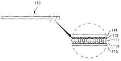
- FIG. 2is a cross-sectional view illustrating ZRF in a digital photographing apparatus according to an embodiment of the present invention.
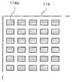
- FIG. 4is a plan view illustrating a second polarizing plate in a digital photographing apparatus according to an embodiment of the present invention.
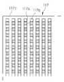
- FIG. 5is a plan view illustrating another example of the first flat plate in the digital photographing apparatus according to the exemplary embodiment.
- FIG. 6is a plan view illustrating another example of the second flat plate in the digital photographing apparatus according to the exemplary embodiment of the present invention.
- FIGS. 5 and 6are cross-sectional views of FIGS. 5 and 6.
- FIG 8 and 9are conceptual views for explaining the operation of the image quality improving apparatus according to an embodiment of the present invention.
- FIG. 10is a flowchart illustrating a method of improving image quality according to an embodiment of the present invention.
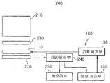
- FIG. 1is a block diagram showing a digital photographing apparatus according to an embodiment of the present invention.
- the lens unit 210collects light to form an image on the image sensor 120.
- the lens unit 210may include a single lens or a plurality of lenses.
- the image sensor 220is installed at the rear of the lens unit 210 and may be formed of a charge coupled device (CCD) or a complementary metal oxide semiconductor (CMOS), and an image focused on a chip surface is charged on an individual element. Accumulated in packets, these packets are output and converted into video for display. Meanwhile, an IR cut filter 230 may be installed at the front of the image sensor 220 to be positioned behind the lens unit 210.
- the IR cut filter 230is a filter for blocking the infrared rays to improve the color sensor because the image sensor recognizes not only visible light but also infrared light, and reacts with light.
- the main controller 240controls the image acquired by the image sensor 220 to be stored as data in the memory unit 250 according to an operation signal or a predetermined process by the operation unit, and outputs the data to the outside through the display unit as necessary. Can be controlled.
- the image quality improvement unitis installed to control the light transmittance irradiated to the image sensor 220 to reduce the brightness difference between the regions in the image obtained by the image sensor 220, which is an image quality improving apparatus according to an embodiment of the present invention ( 100). Therefore, the image quality improvement unit will be described instead with the image quality improvement apparatus 100 according to an embodiment of the present invention.
- the image quality improving apparatus 100may include a zone collected reduction filter (ZRF), an image processor 120, and a ZRF controller 130.
- ZRFzone collected reduction filter
- the ZRF 110is installed between the lens unit 210 and the image sensor 220, transmits the light passing through the lens unit 210 to the image sensor 220, and is configured in a pixel manner.
- an LCD (Liquid Crystal Display) 111(shown in FIG. 2) has an active array and an optical transmittance is adjusted for each area divided into a plurality of regions by unit cell driving.
- the LCD 111is composed of a plurality of pixels whose transmittance is adjusted.
- the active arrayis controlled by the ZRF control unit 130, and may be a power supply circuit for supplying the power required for driving to each of the unit cells consisting of a single or multiple pixels, the size of the voltage for each of the unit cells, The application time is adjusted. Therefore, the LCD 111 may adjust the light transmittance of the pixel by the magnitude of the voltage applied by the ZRF controller 130, the application time of the voltage, and the like.
- a regionmay be one unit in which light transmittance is adjusted by the ZRF controller 130, may be formed of one or a plurality of pixels, and a partition may be set by the ZRF controller 130.
- the ZRF 110moves toward the image sensor 220 between the IR cut filter 230 and the image sensor 220. Can be installed to strike.
- each area of the LCD 111may be configured to correspond to a plurality of pixels in the image sensor 220, which is just one example and may be configured to correspond to a single pixel in the image sensor 220.
- each of the first and second flat plate plates 114 and 115may be polarized in the X-axis and Y-axis directions, for example, but is not limited thereto. For example, it may have a polarization degree of 0.8 ⁇ 0.96.
- the first and second polarizing plates 114 and 115may be, for example, discontinuously formed in the polarization regions 114a and 115a, that is, regions in which light is polarized, in an equal width or length in one direction, and the polarization regions 114a and 115a. Discontinuous arrays of can be formed in plural alongside.
- the first and second polarizing plates 114 and 115may have uneven width or length in one direction, as well as a single polarization area as a whole.
- the patterning of the uneven parts 116a and 117amay be formed using a unit process for manufacturing a semiconductor, such as a photo process or an etching process.
- a plurality of rows of concave-convex shapes consisting of grooves and protrusions corresponding to the concave-convex portions 116a and 117aare formed in plural to correspond to the concave-convex portions 116a and 117a as in this embodiment, or as another example. It may be formed in a single side to be formed side by side so that a plurality of uneven parts 116a, 117a in the width direction.
- the image processor 120may process the image acquired by the image sensor 220 as data for calculating brightness for each of a plurality of divided regions, and output the data to the ZRF controller 130.
- the ZRF controller 130calculates the brightness of a plurality of divided regions of the image from the data processed by the image processor 120, and adjusts the light transmittance of the region of the LCD 111 to reduce the brightness difference between the regions in the image. To control.
- the ZRF 110is configured to be normally white, so that when no voltage is applied, light may be transmitted to have maximum luminance.
- the ZRF controller 130may be configured such that the brightness difference of the area divided into a plurality of regions by arbitrary setting from the data processed by the image processor 120 may be reduced to a normal range, for example, deterioration in image quality.
- the control of the light transmittance of the area of the LCD 111may be minimized, or the control of the light transmittance may not be performed.
- the minimum stepmay refer to a step of minimizing the change in the light transmittance when the light transmittance of the area of the LCD 111 is set to a plurality of steps. In this case, the brightness difference between the areas in the image may be generated. The area of the LCD 111 corresponding to the area may be performed.
- the ZRF controller 130extracts a light defective area from a region of an image acquired by the image sensor 220 and deviates from a predetermined brightness difference compared to the overall brightness.
- the correction regionis extracted as a region contributing to the formation of the light
- the region which transmits the light irradiated to the correction regionis extracted as the adjustment region
- the light transmittance of the adjustment regionis inversely proportional to the brightness of the light defective region.
- the overall brightnessis the brightness of the whole image by the grade or numerical value
- the brightness degree of each image areais determined by the grade or the numerical value and averaged, or other methods of calculating and determining the brightness difference.
- the predetermined brightness differencemay mean that an allowable range of the brightness difference between some or all areas and any one area is represented by a grade or a numerical value.
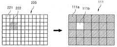
- the ZRF controller 130may include light corresponding to light saturation in an area of an image acquired by the image sensor 220, for example, an area that is excessively brighter than the overall brightness due to a subject emitting strong light. Defect area is extracted, and the correction area 222 is extracted as an area contributing to the formation of the light defective area from the areas 221 and 222 of the image sensor 220, and the correction area is selected from the areas 111a and 111b of the LCD 111. An area through which light irradiated at 222 is transmitted may be extracted as the adjustment area 111b, and the light transmittance of the adjustment area 111b may be adjusted to be lowered at a ratio set according to the brightness of the light defective area.
- the light defective area, the correction area 222, and the adjustment area 111bmay be composed of a single area or a plurality of areas among the areas partitioned by the setting in the corresponding object.
- the ZRF controller 130may have a light deficiency corresponding to a light shortage as an area that is excessively dark compared to the overall brightness due to a dark subject caused by backlight, for example, in an area of an image acquired by the image sensor 220.
- the regionis extracted, and the correction region 222 is extracted as an area contributing to the formation of the light defective region among the regions 221 and 222 of the image sensor 220, and the correction region (from the regions 111a and 111b of the LCD 111).
- the area for transmitting the light irradiated to 222may be extracted as the adjustment area 111b, and the light transmittance of the adjustment area 111b may be adjusted to be set at a ratio set according to the brightness of the light defective area.
- the image quality improving method according to an embodiment of the present inventionis a method using the image quality improving apparatus 100 according to an embodiment of the present invention, and the ZRF 110 and the image processing unit 120 of the image quality improving apparatus 100 described above. Since the configuration of the ZRF control unit 130 and the like and the embodiments thereof are applied in the same manner, a description of these configurations will be omitted.
- an imageis acquired from an image sensor 220 in which light is irradiated through the lens unit 210 and a zone collected reduction filter (ZRF) 110. (S11). Then, the image acquired by the image sensor 220 is processed by the image processor 120 as data (S12).
- the ZRF controller 130calculates the brightness of a plurality of divided regions of the image from the data processed by the image processor 120 (S13). When the CFR controller 130 calculates the brightness for each region of the image, the CFR controller 130 controls the light transmittance for a plurality of regions divided by the LCD 111 of the ZRF 110 to reduce the brightness difference between the regions in the image (S14).
- step S14the light transmittance is adjusted by the ZRF controller 130 to extract a light defective area from the area of the image acquired by the image sensor 220 as an area deviating from a predetermined brightness difference compared to the overall brightness.
- the correction regionis extracted from the region of the sensor 220 as a region contributing to the formation of the light defective region, and the region transmitting the light irradiated to the correction region from the region of the LCD 111 is extracted as the adjusting region.
- the light transmittancecan be adjusted in inverse proportion to the brightness of the light defective area. A detailed description thereof has been given above with reference to FIGS. 8 and 9.
- the imagecan be obtained again by the image sensor 220, before the light transmittance is corrected by the LCD 111 in advance, even in situations such as light saturation or light shortage At the same time, it is possible to obtain images with excellent color reproduction.
- the digital photographing apparatushaving the same, and the image quality improving method according to the present invention, if there is an excessive brightness difference due to light saturation or light deficiency for each region in one screen, it is installed between the camera lens and the image sensor.
- ZRFZero collected Reduction Filter
- the lightis installed between the lens unit and the image sensor and transmits the light passing through the lens unit to irradiate the image sensor, is configured in a pixel manner, the unit cell by placing an active array (active array) Zone collected Reduction Filter (ZRF) having an LCD (Liquid Crystal Display) in which light transmittance is adjusted for each area partitioned by driving;
- An image processorwhich processes an image acquired by the image sensor as data;
- a ZRF controllerconfigured to calculate brightness of a plurality of divided regions of the image from the data processed by the image processor, and to control light transmittance of the region of the LCD to reduce the brightness difference between the regions in the image.
- An image quality improving deviceis provided.
- the ZRFmay be installed to be biased toward the image sensor between the IR cut filter installed between the lens unit and the image sensor and the image sensor.
- the ZRFincludes glass attached to both sides of the LCD, and first and second polarizing plates for polarizing light in a direction orthogonal to each other on the exposed surfaces of the glass, respectively, and are normally white.
- the ZRF controlleris configured to minimize the control of the light transmittance of the area of the LCD when the brightness difference of a plurality of areas divided in the image from the data processed by the image processor is within a normal range, It is possible to avoid performing control of the transmittance.
- the LCDmay have an area corresponding to a plurality of pixels as one unit in the image sensor.
- polarization regionsmay be uniformly or unevenly discontinuously formed in one direction, and a plurality of discontinuous arrangements of the polarization regions may be formed side by side.
- the first and second polarizersmay be formed of a wire grid polarizer.
- the first and second polarizing platesare formed on the substrate of the light transmissive material so that the uneven parts made of a light-transmissive dielectric material or polymer are patterned in the uneven shape in one direction and side by side, and are inclined in the same direction for each inside of the grooves of the uneven parts.
- White metalcan be deposited.
- the ZRF controllerextracts a light failure region as a region that deviates from a predetermined brightness difference from the overall brightness among the regions of the image, and extracts a correction region as a region that contributes to the formation of the light failure region among the regions of the image sensor. And extracting, as an adjusting region, a region that transmits light irradiated to the correction region from the area of the LCD, and adjusting the light transmittance of the adjusting region to be inversely proportional to the brightness of the light defective region.
- the lens unitis incident light; An image sensor installed at the rear of the lens unit; A main control unit controlling the image acquired by the image sensor to be stored in a memory unit; And an image quality improvement unit installed to control the light transmittance irradiated to the image sensor so as to reduce the brightness difference between the regions in the image acquired by the image sensor.
- the image quality improvement unitmay further improve image quality according to an aspect of the present invention.
- a digital photographing apparatuswhich is an apparatus, is provided.
- the digital photographing apparatusmay be any one of a portable digital camera, a CCTV camera, a camera of a portable electronic device, a web camera, a camera module of a vision inspector, and a camera module of a black box.
- ZRFZone collected Reduction Filter
- the adjusting of the light transmittancemay include extracting a light defective area as an area deviating from a predetermined brightness difference from the overall brightness among the areas of the image, and correcting it as an area contributing to the formation of the light defective area from the area of the image sensor.
- An areamay be extracted, and an area for transmitting light irradiated to the correction area among the areas of the LCD may be extracted as an adjustment area, and the light transmittance of the adjustment area may be adjusted in inverse proportion to the brightness of the light defective area.
- the present inventionis industrially applicable to digital photographing apparatus.
- IR cut filter 240main control unit
Landscapes
- Engineering & Computer Science (AREA)
- Multimedia (AREA)
- Signal Processing (AREA)
- Blocking Light For Cameras (AREA)
- Studio Devices (AREA)
Abstract
Description
Translated fromKorean본 발명은 화질 개선 장치, 이를 가지는 디지털 촬영 장치 및 화질 개선 방법에 관한 것으로서, 보다 상세하게는 하나의 화면 내에서 영역별 광포화 또는 광부족으로 인해 과도한 밝기차가 존재하더라도 선명도와 색재현성이 우수한 영상을 획득하도록 하는 화질 개선 장치, 이를 가지는 디지털 촬영 장치 및 화질 개선 방법에 관한 것이다.The present invention relates to an image quality improving apparatus, a digital photographing apparatus having the same, and a method for improving image quality, and more particularly, an image having excellent sharpness and color reproducibility even when there is an excessive brightness difference due to light saturation or lack of light in each region within a screen. The present invention relates to a device for improving image quality, a digital photographing device having the same, and a method for improving image quality.
일반적으로, 디지털 카메라는 필름이 아닌 CCD(Charge Coupled Device)나 CMOS(Complementary Metal Oxide Semiconductor)인 이미지 센서(image sensor)에 영상을 투사하여 촬영하며, 메모리 카드 등의 디지털 방식의 저장 매체에 사진을 기록한다.In general, a digital camera projects an image onto an image sensor, which is a Charge Coupled Device (CCD) or a Complementary Metal Oxide Semiconductor (CMOS), not a film, and captures a photo on a digital storage medium such as a memory card. Record it.
이와 같은 디지털 카메라는 이미지센서에 맺는 면에서 광의 과도한 밝기로 인한 광포화 또는 그 반대로 광의 과도한 부족으로 인한 광부족 현상이 있을 경우, 오토 화이트 밸런스(Auto White Balance, AWB) 기능을 화면 전체에 부여하여, 이를 개선하도록 하고 있다. 이때, 영역별 광의 포화나 부족현상으로 화면의 선명도와 색재현성에 문제가 발생한다.Such a digital camera provides an auto white balance (AWB) function to the entire screen when there is a light saturation due to excessive brightness of light or vice versa due to excessive brightness of the light on the image sensor. We are trying to improve it. At this time, the saturation or lack of light in each area causes problems in the sharpness and color reproduction of the screen.
또한 디지털 카메라는 가시광영역과 센서감도영역에 차이가 발생한 경우, 하나의 화면 전체영역에서 실제 가시광영역 이외의 광이 노이즈로 작용하므로, 컬러필터를 사용하여 원하는 파장대역을 투과하도록 하고, 원치않는 파장대역을 적절히 조절하여 광의 밝기를 조절하는 방법으로 화면의 선명도를 증가시키고, 컬러를 배분하는 방법으로 사진을 촬영하거나 동영상을 기록하는 방법을 사용하고 있다.In addition, when a difference occurs between the visible light region and the sensor sensitivity region, the digital camera operates as a noise of light outside the actual visible region in one entire screen. By adjusting the band appropriately to adjust the brightness of the light to increase the sharpness of the screen, and to distribute the color to take a picture or record a video.
종래 디지털 카메라에서 화질을 개선시키기 위한 기술로는 한국공개실용신안 제20-2001-0002331호의 "광차단층으로서 적층된 칼라필터를 갖는 씨모스이미지센서", 한국공개특허 제10-2007-0078463호의 "이미지 센서 노이즈 저감 장치 및 방법" 등이 개시된 바 있다.As a technique for improving the image quality in a conventional digital camera, "seam image sensor having a color filter laminated as a light blocking layer" of Korean Utility Model Publication No. 20-2001-0002331, "Korean Patent No. 10-2007-0078463" Image sensor noise reduction apparatus and method "and the like.
그러나, 이러한 종래 기술들은 디지털 카메라로 촬영시, 하나의 화면 내에서 광포화나 광부족 현상으로 인해, 과도한 밝기차가 존재할 경우, 촬영 영상의 선명도와 색재현성을 확보하는데 한계를 가지는 문제점을 가지고 있었다.However, these conventional technologies have a problem in that when shooting with a digital camera, if there is an excessive brightness difference due to light saturation or light shortage in one screen, the sharpness and color reproducibility of the captured image are secured.
상기한 바와 같은 종래 기술의 문제점을 해결하기 위하여, 본 발명은 하나의 화면 내에서 영역별 광포화 또는 광부족으로 인해 과도한 밝기차가 존재할 경우, 렌즈유닛과 이미지센서 사이에 설치된 ZRF(Zone collected Reduction Filter)에 의해 부분별 광투과율을 조절함으로써, 선명도와 색재현성이 우수한 영상을 획득하도록 하는데 목적이 있다. 본 발명의 다른 목적들은 이하의 실시례에 대한 설명을 통해 쉽게 이해될 수 있을 것이다.In order to solve the problems of the prior art as described above, the present invention is a ZRF (Zone collected Reduction Filter) installed between the lens unit and the image sensor when there is an excessive brightness difference due to light saturation or lack of light in each area in one screen By adjusting the light transmittance for each part by), the purpose is to obtain an image with excellent clarity and color reproducibility. Other objects of the present invention will be readily understood through the following description of the embodiments.
상기한 바와 같은 목적을 달성하기 위해, 본 발명의 일측면에 따르면, 렌즈유닛과 이미지센서 사이에 설치되어 상기 렌즈유닛을 통과한 광을 상기 이미지센서에 조사하도록 투과시키고, 픽셀방식으로 구성되며, 액티브 어레이(active array)를 두어 단위 셀 구동에 의해, 다수로 구획되는 영역마다 광투과율이 조절되는 LCD(Liquid Crystal Display)를 가지는 ZRF(Zone collected Reduction Filter); 상기 이미지센서에 의해 획득되는 영상을 데이터로 처리하는 영상처리부; 및 상기 영상처리부에 의해 처리된 데이터로부터 상기 영상에서 다수로 구획된 영역의 밝기를 산출하고, 상기 영상에서 영역간의 밝기차를 줄이도록 상기 LCD의 영역에 대한 광투과율을 제어하는 ZRF제어부;를 포함하는, 화질 개선 장치가 제공된다.In order to achieve the object as described above, according to an aspect of the present invention, is installed between the lens unit and the image sensor and transmits the light passing through the lens unit to the image sensor, and configured in a pixel manner, Zone collected Reduction Filter (ZRF) having an LCD (Liquid Crystal Display) in which light transmittance is adjusted for each area divided into a plurality of regions by driving an active array and driving a unit cell; An image processor which processes an image acquired by the image sensor as data; And a ZRF controller configured to calculate brightness of a plurality of divided regions of the image from the data processed by the image processor, and to control light transmittance of the region of the LCD to reduce the brightness difference between the regions in the image. An image quality improving device is provided.
상기 ZRF는, 상기 렌즈유닛과 상기 이미지센서 사이에 설치되는 IR 컷 필터와 상기 이미지센서 사이에서 상기 이미지센서측으로 치우치도록 설치될 수 있다.The ZRF may be installed to be biased toward the image sensor between the IR cut filter installed between the lens unit and the image sensor and the image sensor.
상기 ZRF는, 상기 LCD의 양측면에 글래스가 각각 부착되고, 상기 글래스 각각의 노출면에 서로 직교하는 방향으로 광을 각각 편광시키는 제 1 및 제 2 편광판이 부착되며, 노멀리 화이트(nomally white)로 구성되고, 상기 ZRF제어부는, 상기 영상처리부에 의해 처리된 데이터로부터 상기 영상에서 다수로 구획된 영역의 밝기차가 정상 범위 내인 경우, 상기 LCD의 영역에 대한 광투과율의 제어를 최소 단계로 하거나, 광투과율의 제어를 수행하지 않도록 할 수 있다.The ZRF includes glass attached to both sides of the LCD, and first and second polarizing plates for polarizing light in a direction orthogonal to each other on the exposed surfaces of the glass, respectively, and are normally white. And the ZRF controller is configured to minimize the control of the light transmittance of the area of the LCD when the brightness difference of a plurality of areas divided in the image from the data processed by the image processor is within a normal range, It is possible to avoid performing control of the transmittance.
상기 LCD는, 상기 이미지센서에서 다수의 픽셀을 하나의 단위로서 대응하는 영역을 가질 수 있다.The LCD may have an area corresponding to a plurality of pixels as one unit in the image sensor.
상기 제 1 및 제 2 편광판은, 편광영역이 일방향으로 균등 또는 불균등하게 불연속적으로 형성되고, 상기 편광영역의 불연속적인 배열이 나란하게 다수로 형성될 수 있다.In the first and second polarizing plates, polarization regions may be uniformly or unevenly discontinuously formed in one direction, and a plurality of discontinuous arrangements of the polarization regions may be formed side by side.
상기 제 1 및 제 2 편광판은, 와이어 그리드 편광판(wire grid polarizer)으로 이루어질 수 있다.The first and second polarizers may be formed of a wire grid polarizer.
상기 제 1 및 제 2 편광판은, 광투과성 재질의 기판 상에 광투과성의 유전체나 폴리머로 이루어지는 요철부가 일방향으로 요철 형상으로 패터닝되어 나란하도록 다수로 형성되고, 상기 요철부의 홈 내측마다 동일한 방향으로 경사지게 백색금속이 증착될 수 있다.The first and second polarizing plates are formed on the substrate of the light transmissive material so that the uneven parts made of a light-transmissive dielectric material or polymer are patterned in the uneven shape in one direction and side by side, and are inclined in the same direction for each inside of the grooves of the uneven parts. White metal can be deposited.
상기 ZRF제어부는, 상기 영상의 영역 중에서 전체 밝기에 비하여 정해진 밝기차를 벗어나는 영역으로서 광불량영역을 추출하고, 상기 이미지센서의 영역 중에서 상기 광불량영역의 형성에 기여하는 영역으로서 보정영역을 추출하며, 상기 LCD의 영역 중에서 상기 보정영역에 조사되는 광을 투과시키는 영역을 조절영역으로서 추출하며, 상기 조절영역의 광투과율을 상기 광불량영역의 밝기에 반비례하도록 조절할 수 있다.The ZRF controller extracts a light failure region as a region that deviates from a predetermined brightness difference from the overall brightness among the regions of the image, and extracts a correction region as a region that contributes to the formation of the light failure region among the regions of the image sensor. And extracting, as an adjusting region, a region that transmits light irradiated to the correction region from the area of the LCD, and adjusting the light transmittance of the adjusting region to be inversely proportional to the brightness of the light defective region.
본 발명의 다른 측면에 따르면, 광이 입사되는 렌즈유닛; 상기 렌즈유닛의 후방에 설치되는 이미지센서; 상기 이미지센서에 의해 획득되는 영상을 메모리부에 저장되도록 제어하는 메인제어부; 및 상기 이미지센서에 의해 획득되는 영상에서 영역간의 밝기차를 줄이도록 상기 이미지센서에 조사되는 광투과율을 제어하도록 설치되는 화질개선부를 포함하고, 상기 화질개선부는, 본 발명의 일측면에 따른 화질 개선 장치인, 디지털 촬영 장치가 제공된다.According to another aspect of the invention, the lens unit is incident light; An image sensor installed at the rear of the lens unit; A main control unit controlling the image acquired by the image sensor to be stored in a memory unit; And an image quality improvement unit installed to control the light transmittance irradiated to the image sensor so as to reduce the brightness difference between the regions in the image acquired by the image sensor. The image quality improvement unit may further improve image quality according to an aspect of the present invention. A digital photographing apparatus, which is an apparatus, is provided.
상기 디지털 촬영장치는, 휴대용 디지털 카메라, CCTV용 카메라, 휴대용 전자기기의 카메라, 웹 카메라, 비젼검사기의 카메라모듈, 블랙박스의 카메라모듈 중 어느 하나일 수 있다.The digital photographing apparatus may be any one of a portable digital camera, a CCTV camera, a camera of a portable electronic device, a web camera, a camera module of a vision inspector, and a camera module of a black box.
본 발명의 또 다른 측면에 따르면, 광이 렌즈유닛과 ZRF(Zone collected Reduction Filter)를 통과하여 조사되는 이미지센서로부터 영상을 획득하는 단계; 상기 영상을 데이터로 처리하는 단계; 상기 데이터로부터 상기 영상에서 다수로 구획된 영역의 밝기를 산출하는 단계; 및 상기 영상에서 영역간의 밝기차를 줄이도록 상기 ZRF의 LCD에서 다수로 구획되는 영역에 대한 광투과율을 제어하는 단계;를 포함하는, 화질 개선 방법이 제공된다.According to another aspect of the invention, the step of obtaining an image from the image sensor irradiated with light passing through the lens unit and Zone collected Reduction Filter (ZRF); Processing the image into data; Calculating brightness of a plurality of divided regions of the image from the data; And controlling light transmittance for a plurality of divided regions in the LCD of the ZRF so as to reduce the brightness difference between the regions in the image.
상기 광투과율을 조절하는 단계는, 상기 영상의 영역 중에서 전체 밝기에 비하여 정해진 밝기차를 벗어나는 영역으로서 광불량영역을 추출하고, 상기 이미지센서의 영역 중에서 상기 광불량영역의 형성에 기여하는 영역으로서 보정영역을 추출하며, 상기 LCD의 영역 중에서 상기 보정영역에 조사되는 광을 투과시키는 영역을 조절영역으로서 추출하며, 상기 조절영역의 광투과율을 상기 광불량영역의 밝기에 반비례하도록 조절할 수 있다.The adjusting of the light transmittance may include extracting a light defective area as an area deviating from a predetermined brightness difference from the overall brightness among the areas of the image, and correcting it as an area contributing to the formation of the light defective area from the area of the image sensor. An area may be extracted, and an area for transmitting light irradiated to the correction area among the areas of the LCD may be extracted as an adjustment area, and the light transmittance of the adjustment area may be adjusted in inverse proportion to the brightness of the light defective area.
본 발명에 따른 화질 개선 장치, 이를 가지는 디지털 촬영 장치 및 화질 개선 방법에 의하면, 하나의 화면 내에서 영역별 광포화 또는 광부족으로 인해 과도한 밝기차가 존재할 경우, 렌즈유닛과 이미지센서 사이에 설치된 ZRF(Zone collected Reduction Filter)에 의해 부분별 광투과율을 조절함으로써, 선명도와 색재현성이 우수한 영상을 획득할 수 있고, 화면 밝기차에 따른 디지털 촬영장치의 분해능 저감 효과를 줄일 수 있다.According to the image quality improving apparatus, the digital photographing apparatus having the same, and the image quality improving method according to the present invention, when there is an excessive brightness difference due to light saturation or light deficiency for each region in one screen, a ZRF ( By adjusting the light transmittance for each part by Zone collected Reduction Filter, it is possible to obtain an image with excellent clarity and color reproducibility, and to reduce the resolution reduction effect of the digital photographing apparatus according to the screen brightness difference.
도 1은 본 발명의 일 실시례에 따른 디지털 촬영 장치를 도시한 구성도이다.1 is a block diagram showing a digital photographing apparatus according to an embodiment of the present invention.
도 2는 본 발명의 일 실시례에 따른 디지털 촬영 장치에서 ZRF를 도시한 단면도이다.2 is a cross-sectional view illustrating ZRF in a digital photographing apparatus according to an embodiment of the present invention.
도 3은 본 발명의 일 실시례에 따른 디지털 촬영 장치에서 제 1 평광판을 도시한 평면도이다.3 is a plan view illustrating a first flat plate in the digital photographing apparatus according to the exemplary embodiment of the present invention.
도 4는 본 발명의 일 실시례에 따른 디지털 촬영 장치에서 제 2 편광판을 도시한 평면도이다.4 is a plan view illustrating a second polarizing plate in a digital photographing apparatus according to an embodiment of the present invention.
도 5는 본 발명의 일 실시례에 따른 디지털 촬영 장치에서 제 1 평광판의 다른 예를 도시한 평면도이다.5 is a plan view illustrating another example of the first flat plate in the digital photographing apparatus according to the exemplary embodiment.
도 6은 본 발명의 일 실시례에 따른 디지털 촬영 장치에서 제 2 평광판의 다른 예를 도시한 평면도이다.6 is a plan view illustrating another example of the second flat plate in the digital photographing apparatus according to the exemplary embodiment of the present invention.
도 7은 도 5 및 도 6의 단면도이다.7 is a cross-sectional view of FIGS. 5 and 6.
도 8 및 도 9는 본 발명의 일 실시례에 따른 화질 개선 장치의 동작을 설명하기 위한 개념도이다.8 and 9 are conceptual views for explaining the operation of the image quality improving apparatus according to an embodiment of the present invention.
도 10은 본 발명의 일 실시례에 따른 화질 개선 방법을 도시한 흐름도이다.10 is a flowchart illustrating a method of improving image quality according to an embodiment of the present invention.
본 발명은 다양한 변경을 가할 수 있고, 여러 가지 실시례를 가질 수 있는 바, 특정 실시례들을 도면에 예시하고, 상세하게 설명하고자 한다. 그러나, 이는 본 발명을 특정한 실시 형태에 대해 한정하려는 것이 아니고, 본 발명의 기술 사상 및 기술 범위에 포함되는 모든 변경, 균등물 내지 대체물을 포함하는 식으로 이해되어야 하고, 여러 가지 다른 형태로 변형될 수 있으며, 본 발명의 범위가 하기 실시례에 한정되는 것은 아니다.As the inventive concept allows for various changes and numerous embodiments, particular embodiments will be illustrated in the drawings and described in detail in the written description. However, this is not intended to limit the present invention to the specific embodiments, but should be understood in a way that includes all changes, equivalents, and substitutes included in the spirit and scope of the present invention, and may be modified in various other forms. It is to be understood that the scope of the present invention is not limited to the following examples.
이하, 첨부된 도면을 참조하여 본 발명에 따른 실시례를 상세히 설명하며, 도면 부호에 관계없이 동일하거나 대응하는 구성요소에 대해서는 동일한 참조 번호를 부여하고, 이에 대해 중복되는 설명을 생략하기로 한다.Hereinafter, exemplary embodiments of the present invention will be described in detail with reference to the accompanying drawings, and like reference numerals denote the same or corresponding elements regardless of reference numerals, and redundant description thereof will be omitted.
도 1은 본 발명의 일 실시례에 따른 디지털 촬영 장치를 도시한 구성도이다.1 is a block diagram showing a digital photographing apparatus according to an embodiment of the present invention.
도 1을 참조하면, 본 발명의 일 실시례에 따른 디지털 촬영 장치(200)는 렌즈유닛(210), 이미지센서(220), 메인제어부(240) 및 화질개선부를 포함할 수 있으며, 휴대용 디지털 카메라, CCTV용 카메라, 휴대용 전자기기의 카메라, 웹 카메라, 비젼검사기의 카메라모듈, 블랙박스의 카메라모듈 중 어느 하나를 비롯하여, 다양한 디지털 촬영장치가 해당될 수 있으며, 사용 형태에 따라 카메라로서의 기능을 수행하기 위하여, 케이싱, 디스플레이부, 조작부, 배터리 등을 비롯하여, 필요한 부가구성이 추가될 수 있다. 여기서 휴대용 디지털 카메라는 컴팩트 디지털 카메라, DSLR(Digital Single Lens Reflex) 카메라, 미러리스 카메라를 비롯하여 휴대가 가능한 다양한 디지털 촬영장치를 포함할 수 있다.Referring to FIG. 1, the
렌즈유닛(210)은 이미지센서(120)에 상이 맺히도록 광을 모으는 역할을 하는데, 이를 위해 단일 또는 다수의 렌즈를 포함할 수 있다.The
이미지센서(220)는 렌즈유닛(210)의 후방에 설치되고, CCD(Charge Coupled Device)나 CMOS(Complementary Metal Oxide Semiconductor)로 이루어질 수 있으며, 칩 면에 초점을 맺은 영상이 개개의 요소상에 전하 패킷으로 축적되고, 이들 패킷이 출력되어 영상으로 변환 처리되어 표시되도록 한다. 한편, 이미지센서(220)의 전방에는 렌즈유닛(210)의 후방에 위치하도록 IR 컷 필터(IR cut fillter; 230)가 설치될 수 있다. 이러한 IR 컷 필터(230)는 이미지센서가 가시광선 뿐만 아니라, 적외선도 광으로 인식하여 반응하게 됨으로써, 눈으로 인식하는 색감과 다른 색감으로 나타내므로, 이를 개선하기 위하여 적외선을 차단하도록 하는 필터이다.The
메인제어부(240)는 조작부에 의한 조작신호나 미리 정해진 프로세스에 따라 이미지센서(220)에 의해 획득되는 영상을 메모리부(250)에 데이터로 저장되도록 제어하고, 필요에 따라 디스플레이부를 통해서 외부로 출력하도록 제어할 수 있다.The
화질개선부는 이미지센서(220)에 의해 획득되는 영상에서 영역간의 밝기차를 줄이도록 이미지센서(220)에 조사되는 광투과율을 제어하도록 설치되는데, 이는 본 발명의 일 실시례에 따른 화질 개선 장치(100)로 이루어질 수 있다. 따라서, 화질개선부에 대해서는 본 발명의 일 실시례에 따른 화질 개선 장치(100)로 대신 설명하기로 한다.The image quality improvement unit is installed to control the light transmittance irradiated to the
본 발명의 일 실시례에 따른 화질 개선 장치(100)는 ZRF(Zone collected Reduction Filter; 110), 영상처리부(120) 및 ZRF제어부(130)를 포함할 수 있다.The image
ZRF(110)는 렌즈유닛(210)과 이미지센서(220) 사이에 설치되어, 렌즈유닛(210)을 통과한 광을 이미지센서(220)에 조사하도록 투과시키고, 픽셀(pixel)방식으로 구성되며, 액티브 어레이(active array)를 두어 단위 셀 구동에 의해 다수로 구획되는 영역마다 광투과율이 조절되는 LCD(Liquid Crystal Display; 111)(도 2에 도시)를 가진다. LCD(111)는 투과율이 조절되는 다수의 픽셀로 이루어진다. 또한 액티브 어레이는 ZRF제어부(130)에 의해 제어되며, 단일 또는 다수의 픽셀로 이루어지는 단위 셀 각각에 구동에 필요한 전원을 공급하는 전원 공급 회로일 수 있는데, 단위 셀 각각에 대한 전압의 크기, 전압의 인가시간을 조절하게 된다. 따라서 LCD(111)는 픽셀의 광투광율이 ZRF제어부(130)에 의해 인가되는 전압의 크기, 전압의 인가시간 등에 의해 조절될 수 있다.The ZRF 110 is installed between the
LCD(111)에서 영역은 ZRF제어부(130)에 의해 광투과율이 조절되는 하나의 단위일 수 있으며, 하나 또는 다수의 픽셀로 이루어질 수 있고, ZRF제어부(130)에 의해 그 구획이 설정될 수 있다.In the
렌즈유닛(210)과 이미지센서(220) 사이에 IR 컷 필터(230)가 부가되는 경우, ZRF(110)는 IR 컷 필터(230)와 이미지센서(220) 사이에서 이미지센서(220) 측으로 치우치도록 설치될 수 있다.When the IR cut
도 2를 참조하면, ZRF(110)는 본 실시례에서처럼 LCD(111)의 양측면에 글래스(glass; 112,113)가 각각 부착될 수 있고, 글래스(112,113) 각각의 노출면에 서로 직교하는 방향으로 광을 각각 편광시키는 제 1 및 제 2 편광판(114,115)이 부착될 수 있다. 또한 LCD(111)에서 각 영역은 이미지센서(220)에서 다수의 픽셀에 대응하도록 구성될 수 있는데, 이는 하나의 예시일 뿐, 이미지센서(220)에서 단일 픽셀에 대응하도록 구성될 수 있다.Referring to FIG. 2, in the
도 3 및 도 4에 도시된 바와 같이, 제 1 및 제 2 평관판(114,115) 각각은 일례로 X축 및 Y축 방향으로 각각 편광시킬 수 있고, 이에 한하지 않고, 서로 직교하는 경사방향으로 편광시킬 수도 있으며, 예컨대 0.8~0.96의 편광도를 가질 수 있다. 또한 제 1 및 제 2 편광판(114,115)은 예컨대 편광영역(114a,115a), 즉 광을 편광시키는 영역이 일방향으로 폭이나 길이가 균등하게 불연속적으로 형성될 수 있고, 편광영역(114a,115a)의 불연속적인 배열이 나란하게 다수로 형성될 수 있다. 또한 제 1 및 제 2 편광판(114,115)은 본 실시례와 달리 ,편광영역이 일방향으로 폭이나 길이가 불균등하게 형성될 수 있으며, 이 뿐만 아니라, 편광영역이 전체적으로 단일로 형성될 수도 있다.As shown in FIGS. 3 and 4, each of the first and second
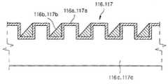
도 5 내지 도 6에 따르면, 제 1 및 제 2 편광판(116,117)은 다른 예로서, 서로 직교하는 방향으로 광을 편광시키는 와이어 그리드 편광판(wire grid polarizer)으로 각각 이루어질 수 있는데, 예컨대 유리나 합성수지 등과 같은 광투과성 재질의 기판(116c,117c) 상에 광투과성의 유전체나 폴리머로 이루어지는 요철부(116a,117a)가 일방향으로 요철 형상으로 패터닝(patterning)되어 나란하도록 다수로 형성될 수 있고, 요철부(116a,117a)의 홈 내측마다 동일한 방향으로 경사지게 은이나 알루미늄 등의 백색금속(116b,117b)이 증착될 수 있다. 요철부(116a,117a)의 패터닝은 포토공정, 에칭공정 등과 같은 반도체 제조용 단위 공정을 이용하여 형성될 수 있다. 기판(116c,117c)에서 요철부(116a,117a)에 대응하는 홈과 돌기로 이루어지는 요철 형상의 열은 본 실시례에서처럼 요철부(116a,117a) 각각에 대응되도록 다수로 형성되거나, 다른 예로서 단일로 형성되어 폭방향으로 요철부(116a,117a)가 다수로 이격되도록 나란하게 형성될 수 있다.5 to 6, the first and
영상처리부(120)는 이미지센서(220)에 의해 획득되는 영상을 다수로 구획된 영역마다 밝기를 산출할 수 있도록 하는 데이터로 처리하고, 이를 ZRF제어부(130)로 출력할 수 있다.The
ZRF제어부(130)는 영상처리부(120)에 의해 처리된 데이터로부터 영상에서 다수로 구획된 영역의 밝기를 산출하고, 영상에서 영역간의 밝기차를 줄이도록 LCD(111)의 영역에 대한 광투과율을 제어한다.The
한편 ZRF(110)는 노멀리 화이트(nomally white)로 구성됨으로써 전압이 인가되지 않았을 경우 광이 투과하여 최대 휘도를 가지도록 할 수 있다. 이 경우 ZRF제어부(130)는 영상처리부(120)에 의해 처리된 데이터로부터 이미지센서(220)에 의해 획득되는 영상에서 임의의 설정에 의해 다수로 구획된 영역의 밝기차가 정상 범위, 예컨대 화질 저하를 고려하지 않을 정도의 밝기차 범위 내인 경우, LCD(111)의 영역에 대한 광투과율의 제어를 최소 단계로 하거나, 광투과율의 제어를 수행하지 않도록 할 수 있다. 여기서 최소 단계는 LCD(111)의 영역에 대한 광투과율을 다수의 단계로 설정할 경우, 광투과율의 변화를 최소로 하는 단계를 의미할 수 있고, 이 경우, 상기한 영상에서 영역간 밝기차를 발생시키는 영역에 대응되는 LCD(111)의 영역에 대해서 수행할 수 있다.On the other hand, the
ZRF제어부(130)는 예컨대 이미지센서(220)에 의해 획득한 영상의 영역 중에서 전체 밝기에 비하여 정해진 밝기차를 벗어나는 영역으로서, 광불량영역을 추출하고, 이미지센서(220)의 영역 중에서 광불량영역의 형성에 기여하는 영역으로서 보정영역을 추출하며, LCD(111)의 영역 중에서 보정영역에 조사되는 광을 투과시키는 영역을 조절영역으로서 추출하며, 조절영역의 광투과율을 광불량영역의 밝기에 반비례하도록 조절할 수 있다. 여기서 전체밝기란 영상의 전체에 대한 밝기를 등급이나 수치별로 정한 것이거나, 영상의 영역별 밝기 정도를 등급이나 수치별로 정하여 이를 평균한 것이거나, 그 밖에 밝기차를 산출 및 판단할 수 있는 다양한 방식으로 정의될 수 있다. 또한 정해진 밝기차란 일부 또는 전체 영역과 어느 하나의 영역간 밝기차의 허용 범위를 등급이나 수치로 나타낼 것을 의미할 수 있다.For example, the
도 8을 참조하면, ZRF제어부(130)는 이미지센서(220)에 의해 획득한 영상의 영역 중에서, 예컨대 강한 광을 발산하는 피사체로 인해 전체 밝기에 비하여 과도하게 밝은 영역으로서 광포화에 해당하는 광불량영역을 추출하고, 이미지센서(220)의 영역(221,222) 중에서 광불량영역의 형성에 기여하는 영역으로서 보정영역(222)을 추출하며, LCD(111)의 영역(111a,111b) 중에서 보정영역(222)에 조사되는 광을 투과시키는 영역을 조절영역(111b)으로서 추출하며, 조절영역(111b)의 광투과율을 광불량영역의 밝기에 따라 설정된 비율로 낮추도록 조절할 수 있다. 이때 광불량영역, 보정영역(222), 조절영역(111b)은 해당하는 대상에서 설정에 의해 구획된 영역 중에서 단일 영역으로 이루어지거나, 다수의 영역으로 이루어질 수 있고, 본 실시례에서는 보정영역(222)이 4개의 영역으로 이루어짐을 나타내며, 조절영역(111b)이 1개의 영역으로 이루어짐을 예시적으로 나타낸다.Referring to FIG. 8, the
도 9를 참조하면, ZRF제어부(130)는 이미지센서(220)에 의해 획득한 영상의 영역 중에서, 예컨대 역광으로 인한 어두운 피사체로 인해 전체 밝기에 비하여 과도하게 어두운 영역으로서 광부족에 해당하는 광불량영역을 추출하고, 이미지센서(220)의 영역(221,222) 중에서 광불량영역의 형성에 기여하는 영역으로서 보정영역(222)을 추출하며, LCD(111)의 영역(111a,111b) 중에서 보정영역(222)에 조사되는 광을 투과시키는 영역을 조절영역(111b)으로서 추출하며, 조절영역(111b)의 광투과율을 광불량영역의 밝기에 따라 설정된 비율로 높이도록 조절할 수 있다.Referring to FIG. 9, the
도 10은 본 발명의 일 실시례에 따른 화질 개선 방법을 도시한 흐름도이다. 본 발명의 일 실시례에 따른 화질 개선 방법은 본 발명의 일 실시례에 따른 화질 개선 장치(100)를 이용한 방법으로서, 앞서 설명한 화질 개선 장치(100)의 ZRF(110), 영상처리부(120) 및 ZRF제어부(130) 등에 대한 구성과 그 실시례들이 동일하게 적용되므로, 이들 구성들에 대한 설명을 생략하기로 한다.10 is a flowchart illustrating a method of improving image quality according to an embodiment of the present invention. The image quality improving method according to an embodiment of the present invention is a method using the image
도 10을 참조하면, 본 발명의 일 실시례에 따른 화질 개선 방법은 광이 렌즈유닛(210)과 ZRF(Zone collected Reduction Filter; 110)를 통과하여 조사되는 이미지센서(220)로부터 영상을 획득한다(S11). 그런 다음, 이미지센서(220)에 의해 획득한 영상을 영상처리부(120)에 의해 데이터로 처리한다(S12). 영상처리부(120)에 의해 처리된 데이터로부터 영상에서 다수로 구획된 영역의 밝기를 ZRF제어부(130)가 산출하도록 한다(S13). CFR제어부(130)는 영상의 영역별 밝기를 산출하면, 영상에서 영역간의 밝기차를 줄이도록 ZRF(110)의 LCD(111)에서 다수로 구획되는 영역에 대한 광투과율을 제어한다(S14).Referring to FIG. 10, in the image quality improving method according to an embodiment of the present invention, an image is acquired from an
광투과율을 조절하는 단계(S14)는 ZRF제어부(130)에 의해, 이미지센서(220)에 의해 획득한 영상의 영역 중에서 전체 밝기에 비하여 정해진 밝기차를 벗어나는 영역으로서 광불량영역을 추출하고, 이미지센서(220)의 영역 중에서 광불량영역의 형성에 기여하는 영역으로서 보정영역을 추출하며, LCD(111)의 영역 중에서 보정영역에 조사되는 광을 투과시키는 영역을 조절영역으로서 추출하며, 조절영역의 광투과율을 광불량영역의 밝기에 반비례하도록 조절할 수 있다. 이에 대한 구체적인 설명은 앞서 도 8 및 도 9를 예로 들어 설명한 바와 같다.In step S14, the light transmittance is adjusted by the
상기한 단계(S11~S14)를 모두 마치면, 이미지센서(220)에 의해 영상을 재차 획득할 수 있고, 그 전에 LCD(111)에 의해 광투과율이 미리 보정됨으로써 광포화나 광부족 등과 같은 상황에서도 선명하면서도 색재현성이 뛰어난 영상을 얻을 수 있다.After completing the above steps (S11 to S14), the image can be obtained again by the
본 발명의 일 실시례에 따른 화질 개선 방법은, 일례로 사용자의 조작이나 정해진 프로세스에 따라, 화질 개선 과정을 수행하도록 하는 신호를 수신받아 수행할 수 있으며, 예컨대 촬영의 사전 절차로서, 오토 포커싱과 동시 또는 오토 포커싱 이후의 절차로서 수행될 수 있고, 다른 예로서, 사용자의 조작이나 정해진 프로세스에 따라, 촬영 과정을 수행하도록 하는 신호를 수신받아 촬영 전에 자동으로 수행될 수도 있다.The image quality improving method according to an embodiment of the present invention may be performed by receiving a signal for performing an image quality improving process according to, for example, a user's operation or a predetermined process. For example, as an advance procedure of shooting, It may be performed as a procedure after simultaneous or auto focusing. As another example, a signal for performing a photographing process may be received and automatically performed before photographing according to a user's manipulation or a predetermined process.
이와 같은 본 발명에 따른 화질 개선 장치, 이를 가지는 디지털 촬영 장치 및 화질 개선 방법에 따르면, 하나의 화면 내에서 영역별 광포화 또는 광부족으로 인해 과도한 밝기차가 존재할 경우, 카메라렌즈와 이미지센서 사이에 설치된 ZRF(Zone collected Reduction Filter)에 의해 부분별 광투과율을 조절함으로써 선명도와 색재현성이 우수한 영상을 획득할 수 있다.According to the image quality improving apparatus, the digital photographing apparatus having the same, and the image quality improving method according to the present invention, if there is an excessive brightness difference due to light saturation or light deficiency for each region in one screen, it is installed between the camera lens and the image sensor. By using the ZRF (Zone collected Reduction Filter) to adjust the light transmittance for each part, it is possible to obtain an image with excellent clarity and color reproducibility.
이와 같이 첨부된 도면을 참조하여 본 발명을 설명하였으나, 본 발명의 기술적 사상을 벗어나지 않는 범위 내에서 다양한 수정 및 변형이 이루어질 수 있음은 물론이다. 그러므로, 본 발명의 범위는 설명된 실시례에 한정되어서는 아니되며, 후술하는 특허청구범위뿐만 아니라 이러한 특허청구범위와 균등한 것들에 의해 정해져야 한다.As described above, the present invention has been described with reference to the accompanying drawings, but various modifications and changes can be made without departing from the spirit of the present invention. Therefore, the scope of the present invention should not be limited to the described embodiments, but should be defined by the claims below and equivalents thereof.
본 발명의 일측면에 따르면, 렌즈유닛과 이미지센서 사이에 설치되어 상기 렌즈유닛을 통과한 광을 상기 이미지센서에 조사하도록 투과시키고, 픽셀방식으로 구성되며, 액티브 어레이(active array)를 두어 단위 셀 구동에 의해, 다수로 구획되는 영역마다 광투과율이 조절되는 LCD(Liquid Crystal Display)를 가지는 ZRF(Zone collected Reduction Filter); 상기 이미지센서에 의해 획득되는 영상을 데이터로 처리하는 영상처리부; 및 상기 영상처리부에 의해 처리된 데이터로부터 상기 영상에서 다수로 구획된 영역의 밝기를 산출하고, 상기 영상에서 영역간의 밝기차를 줄이도록 상기 LCD의 영역에 대한 광투과율을 제어하는 ZRF제어부;를 포함하는, 화질 개선 장치가 제공된다.According to an aspect of the present invention, the light is installed between the lens unit and the image sensor and transmits the light passing through the lens unit to irradiate the image sensor, is configured in a pixel manner, the unit cell by placing an active array (active array) Zone collected Reduction Filter (ZRF) having an LCD (Liquid Crystal Display) in which light transmittance is adjusted for each area partitioned by driving; An image processor which processes an image acquired by the image sensor as data; And a ZRF controller configured to calculate brightness of a plurality of divided regions of the image from the data processed by the image processor, and to control light transmittance of the region of the LCD to reduce the brightness difference between the regions in the image. An image quality improving device is provided.
상기 ZRF는, 상기 렌즈유닛과 상기 이미지센서 사이에 설치되는 IR 컷 필터와 상기 이미지센서 사이에서 상기 이미지센서측으로 치우치도록 설치될 수 있다.The ZRF may be installed to be biased toward the image sensor between the IR cut filter installed between the lens unit and the image sensor and the image sensor.
상기 ZRF는, 상기 LCD의 양측면에 글래스가 각각 부착되고, 상기 글래스 각각의 노출면에 서로 직교하는 방향으로 광을 각각 편광시키는 제 1 및 제 2 편광판이 부착되며, 노멀리 화이트(nomally white)로 구성되고, 상기 ZRF제어부는, 상기 영상처리부에 의해 처리된 데이터로부터 상기 영상에서 다수로 구획된 영역의 밝기차가 정상 범위 내인 경우, 상기 LCD의 영역에 대한 광투과율의 제어를 최소 단계로 하거나, 광투과율의 제어를 수행하지 않도록 할 수 있다.The ZRF includes glass attached to both sides of the LCD, and first and second polarizing plates for polarizing light in a direction orthogonal to each other on the exposed surfaces of the glass, respectively, and are normally white. And the ZRF controller is configured to minimize the control of the light transmittance of the area of the LCD when the brightness difference of a plurality of areas divided in the image from the data processed by the image processor is within a normal range, It is possible to avoid performing control of the transmittance.
상기 LCD는, 상기 이미지센서에서 다수의 픽셀을 하나의 단위로서 대응하는 영역을 가질 수 있다.The LCD may have an area corresponding to a plurality of pixels as one unit in the image sensor.
상기 제 1 및 제 2 편광판은, 편광영역이 일방향으로 균등 또는 불균등하게 불연속적으로 형성되고, 상기 편광영역의 불연속적인 배열이 나란하게 다수로 형성될 수 있다.In the first and second polarizing plates, polarization regions may be uniformly or unevenly discontinuously formed in one direction, and a plurality of discontinuous arrangements of the polarization regions may be formed side by side.
상기 제 1 및 제 2 편광판은, 와이어 그리드 편광판(wire grid polarizer)으로 이루어질 수 있다.The first and second polarizers may be formed of a wire grid polarizer.
상기 제 1 및 제 2 편광판은, 광투과성 재질의 기판 상에 광투과성의 유전체나 폴리머로 이루어지는 요철부가 일방향으로 요철 형상으로 패터닝되어 나란하도록 다수로 형성되고, 상기 요철부의 홈 내측마다 동일한 방향으로 경사지게 백색금속이 증착될 수 있다.The first and second polarizing plates are formed on the substrate of the light transmissive material so that the uneven parts made of a light-transmissive dielectric material or polymer are patterned in the uneven shape in one direction and side by side, and are inclined in the same direction for each inside of the grooves of the uneven parts. White metal can be deposited.
상기 ZRF제어부는, 상기 영상의 영역 중에서 전체 밝기에 비하여 정해진 밝기차를 벗어나는 영역으로서 광불량영역을 추출하고, 상기 이미지센서의 영역 중에서 상기 광불량영역의 형성에 기여하는 영역으로서 보정영역을 추출하며, 상기 LCD의 영역 중에서 상기 보정영역에 조사되는 광을 투과시키는 영역을 조절영역으로서 추출하며, 상기 조절영역의 광투과율을 상기 광불량영역의 밝기에 반비례하도록 조절할 수 있다.The ZRF controller extracts a light failure region as a region that deviates from a predetermined brightness difference from the overall brightness among the regions of the image, and extracts a correction region as a region that contributes to the formation of the light failure region among the regions of the image sensor. And extracting, as an adjusting region, a region that transmits light irradiated to the correction region from the area of the LCD, and adjusting the light transmittance of the adjusting region to be inversely proportional to the brightness of the light defective region.
본 발명의 다른 측면에 따르면, 광이 입사되는 렌즈유닛; 상기 렌즈유닛의 후방에 설치되는 이미지센서; 상기 이미지센서에 의해 획득되는 영상을 메모리부에 저장되도록 제어하는 메인제어부; 및 상기 이미지센서에 의해 획득되는 영상에서 영역간의 밝기차를 줄이도록 상기 이미지센서에 조사되는 광투과율을 제어하도록 설치되는 화질개선부를 포함하고, 상기 화질개선부는, 본 발명의 일측면에 따른 화질 개선 장치인, 디지털 촬영 장치가 제공된다.According to another aspect of the invention, the lens unit is incident light; An image sensor installed at the rear of the lens unit; A main control unit controlling the image acquired by the image sensor to be stored in a memory unit; And an image quality improvement unit installed to control the light transmittance irradiated to the image sensor so as to reduce the brightness difference between the regions in the image acquired by the image sensor. The image quality improvement unit may further improve image quality according to an aspect of the present invention. A digital photographing apparatus, which is an apparatus, is provided.
상기 디지털 촬영장치는, 휴대용 디지털 카메라, CCTV용 카메라, 휴대용 전자기기의 카메라, 웹 카메라, 비젼검사기의 카메라모듈, 블랙박스의 카메라모듈 중 어느 하나일 수 있다.The digital photographing apparatus may be any one of a portable digital camera, a CCTV camera, a camera of a portable electronic device, a web camera, a camera module of a vision inspector, and a camera module of a black box.
본 발명의 또 다른 측면에 따르면, 광이 렌즈유닛과 ZRF(Zone collected Reduction Filter)를 통과하여 조사되는 이미지센서로부터 영상을 획득하는 단계; 상기 영상을 데이터로 처리하는 단계; 상기 데이터로부터 상기 영상에서 다수로 구획된 영역의 밝기를 산출하는 단계; 및 상기 영상에서 영역간의 밝기차를 줄이도록 상기 ZRF의 LCD에서 다수로 구획되는 영역에 대한 광투과율을 제어하는 단계;를 포함하는, 화질 개선 방법이 제공된다.According to another aspect of the invention, the step of obtaining an image from the image sensor irradiated with light passing through the lens unit and Zone collected Reduction Filter (ZRF); Processing the image into data; Calculating brightness of a plurality of divided regions of the image from the data; And controlling light transmittance for a plurality of divided regions in the LCD of the ZRF so as to reduce the brightness difference between the regions in the image.
상기 광투과율을 조절하는 단계는, 상기 영상의 영역 중에서 전체 밝기에 비하여 정해진 밝기차를 벗어나는 영역으로서 광불량영역을 추출하고, 상기 이미지센서의 영역 중에서 상기 광불량영역의 형성에 기여하는 영역으로서 보정영역을 추출하며, 상기 LCD의 영역 중에서 상기 보정영역에 조사되는 광을 투과시키는 영역을 조절영역으로서 추출하며, 상기 조절영역의 광투과율을 상기 광불량영역의 밝기에 반비례하도록 조절할 수 있다.The adjusting of the light transmittance may include extracting a light defective area as an area deviating from a predetermined brightness difference from the overall brightness among the areas of the image, and correcting it as an area contributing to the formation of the light defective area from the area of the image sensor. An area may be extracted, and an area for transmitting light irradiated to the correction area among the areas of the LCD may be extracted as an adjustment area, and the light transmittance of the adjustment area may be adjusted in inverse proportion to the brightness of the light defective area.
본 발명은 디지털 촬영장치에 산업상 이용가능하다.Industrial Applicability The present invention is industrially applicable to digital photographing apparatus.
110 : ZRF 111 : LCD110: ZRF 111: LCD
111a,111b : 영역 112,113 : 글래스111a, 111b: Area 112,113: Glass
114,116 : 제 1 편광판 114a : 편광영역114,116 first
115,117 : 제 2 편광판 115a : 편광영역115,117: second
116a,117a : 요철부 116b,117b : 백색금속116a, 117a:
116c,117c : 기판 120 : 영상처리부116c and
130 : ZRF제어부 210 : 렌즈유닛130: ZRF controller 210: lens unit
220 : 이미지센서 221,222 : 영역220: image sensor 221,222: area
230 : IR 컷 필터 240 : 메인제어부230: IR cut filter 240: main control unit
250 : 메모리부250: memory
Claims (16)
Translated fromKoreanApplications Claiming Priority (2)
| Application Number | Priority Date | Filing Date | Title |
|---|---|---|---|
| KR10-2014-0060776 | 2014-05-21 | ||
| KR1020140060776AKR101592407B1 (en) | 2014-05-21 | 2014-05-21 | Picture quality enhancement apparatus, digital photographing apparatus with the same and picture quality enhancement method thereof |
Publications (1)
| Publication Number | Publication Date |
|---|---|
| WO2015178534A1true WO2015178534A1 (en) | 2015-11-26 |
Family
ID=54554183
Family Applications (1)
| Application Number | Title | Priority Date | Filing Date |
|---|---|---|---|
| PCT/KR2014/006631WO2015178534A1 (en) | 2014-05-21 | 2014-07-22 | Apparatus for improving image quality, digital photography apparatus having same, and method for improving image quality |
Country Status (2)
| Country | Link |
|---|---|
| KR (1) | KR101592407B1 (en) |
| WO (1) | WO2015178534A1 (en) |
Cited By (2)
| Publication number | Priority date | Publication date | Assignee | Title |
|---|---|---|---|---|
| CN113596293A (en)* | 2021-07-08 | 2021-11-02 | 维沃移动通信(杭州)有限公司 | Camera module and electronic equipment |
| WO2022253300A1 (en)* | 2021-06-04 | 2022-12-08 | 简伟明 | Lcd liquid crystal apparatus-based image generation control apparatus and method |
Citations (5)
| Publication number | Priority date | Publication date | Assignee | Title |
|---|---|---|---|---|
| JP2000092383A (en)* | 1998-09-16 | 2000-03-31 | Konica Corp | Image input device, image input method, method for adjusting transmission filter, method for measuring transmission filter and image output method |
| JP2005167465A (en)* | 2003-12-01 | 2005-06-23 | Fuji Photo Film Co Ltd | Digital camera and imaging method of digital camera |
| KR100708938B1 (en)* | 2005-11-07 | 2007-04-17 | 삼성전기주식회사 | LCD light control device, camera module using same and camera using LCD light control device |
| JP2012095219A (en)* | 2010-10-28 | 2012-05-17 | Canon Inc | Imaging apparatus and control method of the same |
| US20130300986A1 (en)* | 2012-05-11 | 2013-11-14 | Industry-Academic Cooperation Foundation Yonsei University | Wire grid polarizer and method for fabricating thereof, liquid crystal display panel and liquid crystal display device having the same |
- 2014
- 2014-05-21KRKR1020140060776Apatent/KR101592407B1/enactiveActive
- 2014-07-22WOPCT/KR2014/006631patent/WO2015178534A1/enactiveApplication Filing
Patent Citations (5)
| Publication number | Priority date | Publication date | Assignee | Title |
|---|---|---|---|---|
| JP2000092383A (en)* | 1998-09-16 | 2000-03-31 | Konica Corp | Image input device, image input method, method for adjusting transmission filter, method for measuring transmission filter and image output method |
| JP2005167465A (en)* | 2003-12-01 | 2005-06-23 | Fuji Photo Film Co Ltd | Digital camera and imaging method of digital camera |
| KR100708938B1 (en)* | 2005-11-07 | 2007-04-17 | 삼성전기주식회사 | LCD light control device, camera module using same and camera using LCD light control device |
| JP2012095219A (en)* | 2010-10-28 | 2012-05-17 | Canon Inc | Imaging apparatus and control method of the same |
| US20130300986A1 (en)* | 2012-05-11 | 2013-11-14 | Industry-Academic Cooperation Foundation Yonsei University | Wire grid polarizer and method for fabricating thereof, liquid crystal display panel and liquid crystal display device having the same |
Cited By (2)
| Publication number | Priority date | Publication date | Assignee | Title |
|---|---|---|---|---|
| WO2022253300A1 (en)* | 2021-06-04 | 2022-12-08 | 简伟明 | Lcd liquid crystal apparatus-based image generation control apparatus and method |
| CN113596293A (en)* | 2021-07-08 | 2021-11-02 | 维沃移动通信(杭州)有限公司 | Camera module and electronic equipment |
Also Published As
| Publication number | Publication date |
|---|---|
| KR101592407B1 (en) | 2016-02-05 |
| KR20150134017A (en) | 2015-12-01 |
Similar Documents
| Publication | Publication Date | Title |
|---|---|---|
| US8049801B2 (en) | Image sensor and imaging apparatus | |
| WO2014189232A1 (en) | Electronic sensor and method for controlling the same | |
| WO2014115984A1 (en) | Photographing device and photographing method for taking picture by using a plurality of microlenses | |
| WO2015178536A1 (en) | Apparatus for improving image quality, digital photography apparatus having same, and method for improving image quality | |
| CN102348051A (en) | Image pickup apparatus | |
| WO2020155739A1 (en) | Image sensor, method for acquiring image data from image sensor, and camera device | |
| JP6760486B2 (en) | Imaging device | |
| TW202131671A (en) | Electronic device | |
| WO2015163653A1 (en) | Imaging device and photographing apparatus | |
| WO2019049193A1 (en) | Sensor module for fingerprint authentication, and fingerprint authentication device | |
| WO2015178534A1 (en) | Apparatus for improving image quality, digital photography apparatus having same, and method for improving image quality | |
| US10104285B2 (en) | Method and apparatus for high resolution digital photography from multiple image sensor frames | |
| KR101613433B1 (en) | Apparatus and method for improving picture quality of digital photographing device | |
| JP2013057769A (en) | Solid state imaging device, imaging device, focus control method and program | |
| US20140210954A1 (en) | Imaging device and imaging apparatus | |
| CN113055575A (en) | Image sensor, camera module and electronic equipment | |
| CN110266928A (en) | Cameras and Electronics | |
| CN114038350B (en) | Display device and imaging method thereof | |
| JP7398284B2 (en) | color image capture device | |
| WO2016003106A2 (en) | Sensor array for multi-aperture camera | |
| CN107197240B (en) | Color difference adjusting method and device of detection equipment | |
| CN115118859A (en) | Electronic device and processing method | |
| CN210016537U (en) | Lens module and imaging system | |
| KR100860699B1 (en) | Camera system with lens shading correction function using color temperature | |
| KR20150139812A (en) | Apparatus and method for improving picture quality of digital photographing device |
Legal Events
| Date | Code | Title | Description |
|---|---|---|---|
| 121 | Ep: the epo has been informed by wipo that ep was designated in this application | Ref document number:14892666 Country of ref document:EP Kind code of ref document:A1 | |
| NENP | Non-entry into the national phase | Ref country code:DE | |
| 122 | Ep: pct application non-entry in european phase | Ref document number:14892666 Country of ref document:EP Kind code of ref document:A1 |