WO2015137629A1 - System for sensing electromyography and motion and control method therefor - Google Patents
System for sensing electromyography and motion and control method thereforDownload PDFInfo
- Publication number
- WO2015137629A1 WO2015137629A1PCT/KR2015/001265KR2015001265WWO2015137629A1WO 2015137629 A1WO2015137629 A1WO 2015137629A1KR 2015001265 WKR2015001265 WKR 2015001265WWO 2015137629 A1WO2015137629 A1WO 2015137629A1
- Authority
- WO
- WIPO (PCT)
- Prior art keywords
- signal
- sensing device
- sensing
- emg
- angle
- Prior art date
- Legal status (The legal status is an assumption and is not a legal conclusion. Google has not performed a legal analysis and makes no representation as to the accuracy of the status listed.)
- Ceased
Links
Images


Classifications
- A—HUMAN NECESSITIES
- A61—MEDICAL OR VETERINARY SCIENCE; HYGIENE
- A61B—DIAGNOSIS; SURGERY; IDENTIFICATION
- A61B5/00—Measuring for diagnostic purposes; Identification of persons
- A61B5/45—For evaluating or diagnosing the musculoskeletal system or teeth
- A61B5/4519—Muscles
- A—HUMAN NECESSITIES
- A61—MEDICAL OR VETERINARY SCIENCE; HYGIENE
- A61B—DIAGNOSIS; SURGERY; IDENTIFICATION
- A61B5/00—Measuring for diagnostic purposes; Identification of persons
- A61B5/24—Detecting, measuring or recording bioelectric or biomagnetic signals of the body or parts thereof
- A61B5/316—Modalities, i.e. specific diagnostic methods
- A61B5/318—Heart-related electrical modalities, e.g. electrocardiography [ECG]
- A61B5/346—Analysis of electrocardiograms
- A61B5/349—Detecting specific parameters of the electrocardiograph cycle
- A61B5/352—Detecting R peaks, e.g. for synchronising diagnostic apparatus; Estimating R-R interval
- A—HUMAN NECESSITIES
- A61—MEDICAL OR VETERINARY SCIENCE; HYGIENE
- A61B—DIAGNOSIS; SURGERY; IDENTIFICATION
- A61B5/00—Measuring for diagnostic purposes; Identification of persons
- A61B5/24—Detecting, measuring or recording bioelectric or biomagnetic signals of the body or parts thereof
- A61B5/316—Modalities, i.e. specific diagnostic methods
- A61B5/389—Electromyography [EMG]
- A—HUMAN NECESSITIES
- A61—MEDICAL OR VETERINARY SCIENCE; HYGIENE
- A61B—DIAGNOSIS; SURGERY; IDENTIFICATION
- A61B2560/00—Constructional details of operational features of apparatus; Accessories for medical measuring apparatus
- A61B2560/04—Constructional details of apparatus
- A61B2560/0462—Apparatus with built-in sensors
- A61B2560/0468—Built-in electrodes
- A—HUMAN NECESSITIES
- A61—MEDICAL OR VETERINARY SCIENCE; HYGIENE
- A61B—DIAGNOSIS; SURGERY; IDENTIFICATION
- A61B5/00—Measuring for diagnostic purposes; Identification of persons
- A61B5/24—Detecting, measuring or recording bioelectric or biomagnetic signals of the body or parts thereof
- A61B5/25—Bioelectric electrodes therefor
- A61B5/279—Bioelectric electrodes therefor specially adapted for particular uses
- A61B5/296—Bioelectric electrodes therefor specially adapted for particular uses for electromyography [EMG]
Definitions
- the present inventionrelates to a system for detecting EMG and motion, and a control method thereof.
- EMGis a curve that records the action potential of muscles.
- needle electrode methodwhich detects activity of the exercise unit by drawing an action potential generated at a point in the muscle by inserting a needle electrode into the muscle.
- Korean Patent Publication No. 2013-0073361which is a prior art, discloses an apparatus and method for classifying EMG signals.
- the inertial sensormay include at least one of a gyro sensor, an acceleration sensor, and a geomagnetic field sensor.
- a motion measuring methodmay not only attach a plurality of sensors to the body, but also may cause inconvenience in measurement because the cables connected to the plurality of sensors are intricately intertwined. Therefore, no cable is required, and a portable EMG and body motion measuring device including an inertial sensor and an EMG sensor is required.
- An object of the present inventionis to provide a system for detecting EMG and motion that can estimate muscle strength during exercise and a control method thereof.
- An object of the present inventionis to provide a system and a control method for detecting EMG and motion that can confirm muscle fatigue.
- the present inventionprovides a system and a control method for detecting EMG and motion that can compare the correlation between the joint angle and muscle strength of a normal person and a patient group.
- an embodiment of the present inventionincludes a case including a groove for positioning the electrode on one side of the outer side of the case, the electrode located in the groove in contact with a portion of the object, the case of A sensing unit including an sensing unit located inside to sense an EMG and an operation of an object, transmitting an EMG signal and an operation signal corresponding to a sensing result to a receiving device, and a battery supplying power to the sensing unit;
- a sensing systemmay include a receiving device that receives an EMG signal and an operation signal and outputs sensing data corresponding to the received EMG signal and the operation signal.
- the sensing unitdetects the motion of the object through a plurality of motion sensors, and generates a motion signal based on the detection result, the EMG signal for generating the EMG signal of the object through the plurality of electrodes It may include a signal generator and a communication unit for transmitting the operation signal and the EMG signal to the receiving device.
- the sensing devicemay further include a button unit for turning on or off an operation of the sensing unit, a light generating unit for generating light related to the operation of the sensing unit, and a charging terminal unit for charging a battery.
- the communication unitmay transmit the EMG signal and the operation signal to the receiving device through wireless communication.
- the electrodehas a cylindrical rod shape, a portion of the center portion of the electrode is accommodated in the groove, and the other portion of the center portion is exposed to contact the portion of the object, the electrode is bent inwardly of the case from the center portion Including two extensions extending, each of the two extensions can be connected to the sensing unit.
- the caseincludes three grooves for positioning each of the first electrode, the second electrode, and the third electrode, and the sensing unit detects EMG through the first electrode, the second electrode, and the third electrode. can do.
- the motion sensormay include a gyro sensor, an acceleration sensor, and a geomagnetic field sensor.
- the sensing deviceis a first sensing device attached to a first position of the object
- the receiving deviceis first sensing data corresponding to the first EMG signal and the first operation signal received from the first sensing device.
- the receiving devicemay generate evaluation data associated with the posture of the object based on the first sensing data and the second sensing data, and output the generated evaluation data.
- the apparatusmay further include an evaluation data output device configured to generate evaluation data associated with the posture of the object based on the output first sensing data and output second sensing data, and output the generated evaluation data. have.
- the receiving devicereceives at least one or more of the first EMG signal, the first operation signal and the first sensing data through the first antenna, the second EMG signal, the second operation signal and the second sensing At least one of the data may be received through the second antenna.
- the evaluation dataincludes an angle with respect to the object, the angle being calculated based on the first motion signal and the second motion signal, wherein the first motion signal is a first gyro sensor signal, a first acceleration sensor.
- the signalmay be generated based on the signal and the first geomagnetic sensor signal, and the second operation signal may be generated based on the second gyro sensor signal, the second acceleration sensor signal, and the second geomagnetic sensor signal.
- the first operational signalcomprises a first orientation and the second operational signal comprises a second orientation, wherein the angle is based on a product between the inverse of the first orientation and the second orientation.
- Computed, where the first orientation is quaternion and the anglemay be Euler angle.
- the sensing devicemay determine at least one angle corresponding to the sensing device based on the gyro sensor signal of the sensing device, and generate the operation signal based on the at least one angle. have.
- the at least one anglemay include a roll angle, a pitch angle and a yaw angle corresponding to the sensing device.
- the sensing devicemay correct the at least one angle based on at least one of an acceleration sensor signal of the sensing device and a geomagnetic field sensor signal of the sensing device.
- the sensing devicedetermines the roll angle, the pitch angle and the yaw angle corresponding to the sensing device based on the gyro sensor signal of the sensing device, and uses the acceleration sensor signal of the sensing device. Correcting the roll angle and the pitch angle, correcting the yaw angle using the geomagnetic sensor signal of the sensing device, and based on the corrected roll angle, the corrected pitch angle and the corrected yaw angle An operation signal can be generated.
- An embodiment of the present inventionincludes a case including a groove for positioning the electrode on one side of the outer side of the case, the electrode is located in the groove in contact with a portion of the object, the inside of the case to detect the EMG and motion of the object
- the present inventionmay provide a sensing device including a sensing unit which transmits an EMG signal and an operation signal corresponding to a sensing result to a receiving apparatus, and a battery which supplies power to the sensing unit.
- the sensing unitdetects the motion of the object through a plurality of motion sensors, and generates a motion signal based on the detection result, the EMG signal for generating the EMG signal of the object through the plurality of electrodes It may include a signal generator and a communication unit for transmitting the operation signal and the EMG signal to the receiving device.
- a method of generating an EMG signal based on a sensing result through an electrode in a sensing devicegenerating an operation signal based on a sensing result through a motion sensor in a sensing device, an EMG signal in a sensing device, and
- the methodmay include transmitting an operation signal to a receiving device, wherein the electrode is located in a groove formed on one surface of the outside of the case of the sensing device and may contact a part of the object.
- any one of the problem solving means of the present invention described aboveit is possible to provide a system and a control method for detecting the EMG and motion that can estimate the muscle strength during exercise. According to any one of the problem solving means of the present invention described above, it is possible to provide a system for detecting EMG and motion that can confirm the fatigue of the muscle and a control method thereof. According to any one of the above-described means for solving the problems of the present invention, it is possible to provide a system and a control method for detecting the EMG and the motion that can compare the correlation between the joint angle and muscle power of the normal group and the patient group.
- any one of the above-described problem solving means of the present inventionby attaching a sensing device to the joints of the whole body, to provide a system and a control method for detecting the EMG and motion that enables analysis of various and complex motions Can be.
- FIG. 1is a diagram illustrating an EMG and a motion detection system according to an exemplary embodiment of the present invention.
- FIG. 2is a block diagram illustrating a sensing device according to an embodiment of the present invention.
- 3A to 3Cillustrate a sensing device according to an embodiment of the present invention.
- 4A to 4Bare diagrams for explaining an example of a process of determining an orientation.
- 5A to 5Billustrate a receiving apparatus according to an embodiment of the present invention.
- FIG. 6is a view illustrating evaluation data associated with a posture of an object according to an embodiment of the present invention.
- FIG. 7is a flowchart illustrating a method of controlling EMG and motion detection according to an embodiment of the present invention.
- the term 'unit'includes a unit realized by hardware, a unit realized by software, and a unit realized by both.
- one unitmay be realized using two or more pieces of hardware, and two or more units may be realized by one piece of hardware.
- the EMG and motion detection system 1is a diagram illustrating an EMG and a motion detection system according to an exemplary embodiment of the present invention.
- the EMG and motion detection system 1includes a control device 100, a reception device 200, and an evaluation data output device 300.
- the EMG and motion detection system 1may be configured differently from FIG. 1.
- the EMG and motion detection system 1may further include a plurality of sensors or may further include a separate communication device (not shown).
- the sensing device 100may be attached to a part of the object to detect the EMG and the motion of the object.
- the sensing device 100may be configured in plural and attached to a part of the object.
- the sensing device 100may simultaneously measure EMG and motion of 6 channels or more.
- the sensing device 100may detect the motion of the object through a plurality of motion sensors and generate an motion signal based on the detection result.
- the plurality of motion sensorsmay include, for example, an acceleration sensor, a gyro sensor, a geomagnetic field sensor, and the like.
- the sensing device 100may generate an EMG signal of the object through the plurality of electrodes.
- the electrodelargely includes a surface electrode for sensing the current of the skin through the skin contact surface and an insertion electrode for inserting a line or a needle, and is composed of a monopolar using one electrode and a bipolar using two electrodes. Can be.
- the electrode included in the sensing device 100may have a cylindrical rod shape, and a portion of the center portion of the electrode may be accommodated in the groove using the surface electrode, and the other portion of the center portion may be exposed to contact a portion of the object.
- Such an electrodemay be attached to the mitral muscle, deltoid muscle, waist portion, arm portion, lower leg portion and leg portion of the upper limb.
- the first sensing device 100amay be attached to the lower arm of the object, and the second sensing device 100b may be attached to the upper arm of the object.
- the first sensing device 100a and the second sensing device 100bmay move the EMG and the motion of the object. Can be detected.
- the sensing device 100may be attached to a portion where the spine is located to measure motion, but is attached to a part of a muscle, such as an arm or a leg, and when walking or taking an elbow, shoulder, knee, thigh. You can measure your back movement and muscle activity signals.
- the sensing device 100may generate an EMG signal and an operation signal corresponding to the sensing result.
- the first sensing device 100a and the second sensing device 100bmay generate an EMG signal and an operation signal corresponding to the sensing result.
- the first operation signalmay be generated based on the first gyro sensor signal, the first acceleration sensor signal, and the first geomagnetic field sensor signal, and the first operation signal may include a first orientation.
- the second operation signalmay be generated based on the second gyro sensor signal, the second acceleration sensor signal, and the second geomagnetic sensor signal, and the second operation signal may include a second orientation.
- the first orientationmay be a quaternion.
- the sensing device 100may transmit an EMG signal and an operation signal corresponding to the sensing result to the receiving device 200.
- each of the first sensing device 100a and the second sensing device 100bmay transmit an EMG signal and an operation signal corresponding to the sensing result to the receiving device 200.
- the sensing device 100may transmit the EMG signal and the operation signal to the receiving device 200 through wireless communication (for example, RF communication).
- the receiving device 200may receive an EMG signal and an operation signal from the sensing device 100.
- the receiving device 200receives at least one or more of the first EMG signal, the first operation signal, and the first sensing data through the first antenna, and the second EMG signal, the second operation signal, and the second sensing data. At least one may be received through the second antenna.
- the receiving device 200may output sensing data corresponding to the received EMG signal and the operation signal.
- the reception apparatus 200may include first sensing data corresponding to the first EMG signal and the first operation signal received from the first sensing apparatus 100a, and a second sensing apparatus attached to a second position of the object.
- the second sensing data corresponding to the second EMG signal and the second operation signal received from 100bmay be output.
- the receiving device 200may generate evaluation data associated with a posture of the object based on the first sensing data and the second sensing data, and output the generated evaluation data.
- the evaluation datamay be generated by the sensing device 100 and transmitted to the receiving device 200.
- the evaluation data output apparatus 300may receive and output evaluation data generated from the reception apparatus 200. In addition, the evaluation data output apparatus 300 may generate evaluation data associated with the posture of the object based on the output first sensing data and output second sensing data and output the generated evaluation data.
- the evaluation data output device 300displays evaluation data through a display, and the display may further include a touch panel for processing a user's touch input as well as a portion for displaying an image such as an LCD and an LED.
- the sensing apparatus 100may include a sensing unit 110, a battery (not shown), an electrode (not shown), and a case (not shown).
- the sensing device 100 shown in FIG. 2is just one implementation example of the present application, and may be modified in various forms based on the components shown in FIG. 2.
- anyone with knowledge ofcan understand. For example, components and functionality provided within those components may be combined into a smaller number of components or further separated into additional components.
- the case (not shown)includes a groove for locating the electrode on one surface of the outside of the case (not shown), and the electrode (not shown) may be positioned in the groove to contact a part of the object.
- the battery 120may supply power to the sensing device 100 or the sensing unit 110.
- Such a case (not shown), an electrode (not shown), and a battery (not shown)will be described below in more detail with reference to FIGS. 3A to 3C.
- the sensing unit 110is located inside the case (not shown) to detect the EMG and the motion of the object, generates an EMG signal and an operation signal corresponding to the detection result, and receives the generated EMG signal and the operation signal ( 200).
- the objectis the body.
- the detector 110may include an operation signal generator 111, an EMG signal generator 112, and a communicator 113.
- the sensing unit 110 illustrated in FIG. 2is just one embodiment of the present disclosure, and may be modified in various forms based on the components illustrated in FIG. 2.
- the motion signal generator 111may detect the motion of the object through a plurality of motion sensors and generate an motion signal corresponding to the detection result.
- the motion sensormay include at least one of a gyro sensor, an acceleration sensor, and a geomagnetic field sensor.
- at least one of the gyro sensor, the acceleration sensor and the geomagnetic field sensoris any one of the motion signal generator 111, the detector 110 or the sensing device 100 in the form of a hardware module, a software module or a combination of the two. Can be included.
- the operation signal generated by the operation signal generator 111may be an output signal of one sensor.
- the operation signalmay be a gyro sensor signal which is an output signal of the gyro sensor.
- the operation signal generated by the operation signal generator 111may be output signals of at least two sensors or a combination thereof.
- the operation signalmay be a combination of a gyro sensor signal that is an output signal of the gyro sensor and a geomagnetic sensor signal that is an output signal of the geomagnetic sensor.
- the operation signal generated by the operation signal generator 111may be a separate signal calculated or generated based on output signals of at least one or more sensors.
- the operation signalmay be an orientation signal generated based on a gyro sensor signal, an acceleration sensor signal, or a geomagnetic sensor signal. Basically, the operation signal may reflect the motion of the body detected by the sensing device 100.
- the EMG signal generator 112may detect EMG of the object.
- the EMG signalmay be an electrical signal generated along the muscle fibers from the muscle surface as the body moves, but is not limited to this definition.
- An example of the magnitude of the EMG signalis 10 mV or less, and an example of the frequency of the EMG signal is a frequency of less than 500 Hz.
- the EMG signal generator 112may detect EMG of the object through at least one electrode.
- the EMG signal generator 112may detect EMG of the object through three electrodes contacting different positions of the body.
- the three electrodesmay be three monopole electrodes that are independent of each other, or may be two bipolar electrodes and one monopole electrode.
- all three electrodesmay be used for one EMG sensor measurement channel.
- Each of the three electrodesmay also be used for each of the different EMG sensor measurement channels.
- the shape of the electrodemay be determined by one of various shapes such as a surface electrode, a needle electrode or a line electrode, and the shape thereof may also be determined by one of various shapes such as a cylindrical shape and a rod shape. If it is assumed that each of the plurality of electrodes has a cylindrical rod shape, a part of the center portion of the electrode is accommodated in the groove of the sensing device 100 or a case (not shown), and the other portion of the center portion of the electrode is used to contact a part of the object. May be exposed.
- the electrodeincludes two extension parts that extend from the center to the inner side of the case, and the EMG signal generator 112 may be connected to each of the two extension parts to detect EMG. For example, when the sensing device 100 is attached to the object, the EMG signal generator 112 may measure the EMG of the object through the first electrode, the second electrode, and the third electrode of the sensing device 100 in contact with the object. It can be detected.
- the communication unit 113may transmit an operation signal and an EMG signal to the receiving device 200. At this time, the communication unit 113 may transmit the EMG signal and the operation signal to the receiving device 200 through wireless communication, an example of a network capable of such wireless communication, Wi-Fi, Internet (Internet), LAN ( Local Area Network (WLAN), Wireless Local Area Network (WLAN), Wide Area Network (WAN), Personal Area Network (PAN), 3G, 4G, LTE, and the like, but are not limited thereto.
- a networkcapable of such wireless communication, Wi-Fi, Internet (Internet), LAN ( Local Area Network (WLAN), Wireless Local Area Network (WLAN), Wide Area Network (WAN), Personal Area Network (PAN), 3G, 4G, LTE, and the like, but are not limited thereto.
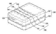
- the sensing device 100may include a sensing unit 110, a battery 120, a case 130, and an electrode 140.
- the sensing device 100 illustrated in FIGS. 3A to 3Cis just one embodiment of the present disclosure, and various modifications may be made based on the components illustrated in FIGS. 3A to 3C. Those skilled in the art can understand. For example, components and functionality provided within those components may be combined into a smaller number of components or further separated into additional components.
- the front part of the sensing device 100may include an upper case 131, a button part 121, and a light generator 122.
- the upper case 131serves to protect the internal circuit that controls the sensing device 100 in combination with the lower case 132 of the rear portion.
- the upper case 131may be made of a material such as plastic, PVC, synthetic resin.
- the button unit 121may turn on or off the operation of the sensing unit 110.
- the light generator 122may generate light related to the operation of the detector 110.
- the light generator 122may use a light emitting diode (LED) to generate light associated with the operation.
- LEDlight emitting diode
- the side of the sensing device 100includes a charging terminal 123, it is possible to charge the battery built in the sensing device 100 through the charging terminal 123.
- FIG. 3Bis a diagram illustrating a rear part and a side part of the sensing device 100.
- the rear surface of the sensing device 100may include a lower case 132, an electrode 140, and a groove 150.
- the lower case 132may include a groove 150 for positioning the electrode 140 on one surface of the outside of the case.
- the lower case 132may include three grooves for positioning each of the first electrode 141, the second electrode 142, and the third electrode 143.
- the lower case 132may be made of a material such as plastic, PVC, synthetic resin.
- Each of the first electrode 141, the second electrode 142, and the third electrode 143may be a conductive metal, and an example of the conductive metal is copper, silver, or an alloy of two or more metals, but is not limited thereto.
- the electrode 140may be positioned in the plurality of grooves 150 recessed in the lower case 132 to contact a part of the object.
- the electrode 140may include at least one electrode 140.
- the electrode 140has a cylindrical rod shape, a part of the center of the electrode is received in the groove 150, and the other part of the center is exposed to contact the part of the object, the electrode is bent inwardly extending from the center of the case It may include two extensions. In this case, each of the two extension parts may be connected to the sensing part 110.
- the lower case 132may include three grooves 150.
- the first electrode 141is connected to the sensing unit 110 through the first groove 151
- the second electrode 142is connected to the sensing unit 110 through the second groove 152.
- the third electrode 143may be connected to the sensing unit 110 through the third groove 153.
- the sensing device 100includes a sensing unit 110, a battery 120, a button unit 121, a light generating unit 122, a charging terminal unit 123, and an electrode 140. can do.
- the button unit 121, the light generating unit 122, the charging terminal unit 123, and the electrode 140are connected to the sensing unit 110, and have the same functions as those of FIGS. 3A to 3B. I'll skip it because it does.
- the sensing unit 110may be located inside the case 130 to detect EMG and motion of the object, and transmit an EMG signal and an operation signal corresponding to the detection result to the receiving device.
- the sensing unit 110may be configured of a circuit (or a circuit device) consisting of one or more electronic components.
- the sensing device 100 or the sensing unit 110may receive power through the battery 120 included in the sensing device 100, and the battery 120 may be disposed between the charging terminal unit 123 and the external power supply device. It can be charged via a connection (or connecting line).
- the first sensing device 100acalculates an angle with respect to an object by using the first operation signal generated by the operation signal generator 111 and the second operation signal received from the second sensing device 100b. I will explain the assumptions. However, as will be described below, according to another embodiment of the present invention, the angle with respect to the object may be calculated by the receiving device 200 or the evaluation data output device 300.
- the receiving device 200calculates an angle with respect to the object
- An angle with respect to the objectmay be calculated using the motion signal.
- the evaluation data output apparatus 300calculates an angle with respect to the object
- the second operation signalmay be received from the second operation signal
- the angle of the objectmay be calculated based on the received first operation signal and the second operation signal
- the first operation signal and the second operation signalmay be received from the receiving device 200. This may be used to calculate an angle with respect to the object.
- the first sensing device 100auses the first operation signal generated by the operation signal generator 111 and the second operation signal received from the second sensing device 100b.
- the following descriptionassumes a configuration for calculating an angle with respect to.
- the motion signal generator of the first sensing device 100a or the first sensing device 100amay detect the motion of the object through a plurality of motion sensors.
- the motion sensormay include a gyro sensor, an acceleration sensor, and a geomagnetic field sensor.
- each of the first sensing device 100a or the second sensing device 100bwill be described as performing an operation, but the operation signal generator or the second sensing device of the first sensing device 100a ( Each operation signal generator of 100b may perform the same operation.
- the first sensing device 100awhen the first sensing device 100a is attached to the upper arm of the body of the object and the second sensing device 100b is attached to the lower arm, the first sensing device 100a generates the first operation signal.
- the second sensing device 100bmay generate a second operation signal.
- the first operation signalmay be generated based on the first gyro sensor signal, the first acceleration sensor signal, and the first geomagnetic sensor signal
- the second operation signalmay be the second gyro sensor signal or the second acceleration sensor signal.
- a second earth magnetic field sensor signala second earth magnetic field sensor signal.
- the first sensing device 100amay calculate an angle with respect to the object based on the first operation signal and the second operation signal.
- the first sensing device 100amay include a roll angle of the first sensing device 100a corresponding to a roll rotation based on at least one of the first gyro sensor signal, the first acceleration sensor signal, and the first geomagnetic sensor signal.
- the pitch angle of the first sensing device 100a corresponding to the pitch rotation and the yaw angle of the first sensing device 100a corresponding to the yaw rotationmay be calculated.
- the rollmeans rotation about the x axis
- the pitchmeans rotation about the y axis
- the yawmeans rotation about the z axis.
- the second sensing device 100bmay further include a roll angle of the second sensing device 100b and a second sensing device based on at least one of a second gyro sensor signal, a second acceleration sensor signal, and a second geomagnetic sensor signal.
- the pitch angle of 100b and the yaw angle of the second sensing device 100bmay be calculated.
- the first sensing device 100amay calculate an angle with respect to the object based on the roll angle, the pitch angle and the yaw angle of the first sensing device 100a and the roll angle, the pitch angle and the yaw angle of the second sensing device 100b. Can be.
- the first sensing device 100aintegrates the angular velocity signal on the x axis of the first sensing device 100a, the angular velocity signal on the y axis of the first sensing device 100a, and the angular velocity signal on the z axis of the first sensing device 100a.
- the yaw angle of the device 100acan be calculated.
- the first sensing device 100acalculates the roll angle of the first sensing device 100a through integration of the angular velocity signal on the x axis of the first sensing device 100a, and the first sensing device 100a.
- the second sensing device 100bmay be configured for the angular velocity signal of the x axis of the second sensing device 100b, the angular velocity signal of the y axis of the second sensing device 100b, and the angular velocity signal of the z axis of the second sensing device 100b.
- the roll angle of the second sensing device 100b corresponding to the roll rotation through the integration, the pitch angle and the yaw rotation of the second sensing device 100b corresponding to the pitch rotation. 2 yaw angle of the sensing device (100b)can be calculated.
- the first sensing device 100auses the acceleration signal on the x axis of the first sensing device 100a, the acceleration signal on the y axis of the first sensing device 100a, and the acceleration signal on the z axis of the first sensing device 100a.
- the initial value of the roll angle of the first sensing device 100a and the initial value of the pitch angle of the first sensing device 100amay be determined.
- an example of determining the initial value of the roll angle and the initial value of the pitch angle by the first sensing device 100a through Equations 1 and 2will be described.
- the first sensing device (100a)is a pie (roll angle) ), The pitch angle theta ( )
- the transformation matrixMay refer to a navigation coordinate system indicating a transformation from a reference coordinate system to a fuselage coordinate system.
- the transformation matrixCan have a transformation of the roll angle, the pitch angle and the yaw angle as elements, and the roll angle, the pitch angle and yaw angle , , It can be expressed as.
- the first sensing device 100ahas a value of 1 (g: gravitational acceleration) in which the z-axis of the three axes of the x-axis, the y-axis, and the z-axis coincides with the middle acceleration direction. ) And each of the other two axes, x and y, is 0. ),
- the pitch angle thetaCan be calculated.
- the first sensing device 100ais a pie, which is a calculated roll angle. ),
- the pitch angle theta ( )Can be determined as the initial value of the roll angle and the initial value of the pitch angle.
- the yaw angleis Psi ( Can be expressed as
- the first sensing device 100areceives the geomagnetic field signal of the x axis of the first sensing device 100a, the geomagnetic field signal of the y axis of the first sensing device 100a, and the z magnetic field signal of the z axis of the first sensing device 100a.
- the initial value of the yaw angle of the first sensing device 100amay be determined.
- the first sensing device 100ais m x , which is the geomagnetic signal on the x-axis of the first sensing device 100a, m y , which is the y-axis signal on the y-axis of the first sensing device 100a, and 1 m z , the transformation matrix, which is the geomagnetic signal on the z-axis of the sensing device 100a And the earth angle Psi (m 1, m 2 , m 3 ) We can calculate the initial value of).
- Equation 1( ) Can be represented by C 1 associated with the roll angle and pitch angle and C 2 associated with the yaw angle, as shown in Equation 4, and Equation 1 is converted into Equation 5 and Equation 6.
- the first sensing device 100ahas a pie angle of roll in Equation 8 ) And the pitch angle theta ( )
- the initial value of yaw anglecan be obtained by substituting m x , m y and m z , which are the geomagnetic signals when each is 0, and m 1 , m 2 and m 3 , which are the values of the earth's geomagnetic vector.
- the first sensing device 100amay determine the initial value of the determined roll angle of the first sensing device 100a, the initial value of the pitch angle of the first sensing device 100a, and the initial value of the yaw angle of the first sensing device 100a. Based on the integration, the angular velocity signal on the x axis of the first sensing device 100a, the angular velocity signal on the y axis of the first sensing device 100a, and the angular velocity signal on the z axis of the first sensing device 100a may be integrated.
- the first sensing device 100aperforms the integration on the angular velocity signal of the x-axis of the first sensing device 100a based on the determined initial value of the roll angle of the first sensing device 100a, and determines the determined first value.
- the integration of the angular velocity signal on the y-axis of the first sensing device 100ais performed based on the initial value of the pitch angle of the first sensing device 100a, and based on the determined initial value of the yaw angle of the first sensing device 100a.
- the second sensing device 100buses the x-axis geomagnetic signal of the second sensing device 100b, the y-axis signal of the y-axis of the second sensing device 100b, and the z-axis geomagnetic signal of the second sensing device 100b.
- the initial value of the yaw angle of the second sensing device 100bmay be determined.
- the second sensing device 100buses an acceleration signal on the x axis of the second sensing device 100b, an acceleration signal on the y axis of the second sensing device 100b, and an acceleration signal on the z axis of the second sensing device 100b.
- the initial value of the roll angle of the second sensing device 100b and the initial value of the pitch angle of the second sensing device 100bmay be determined.
- the second sensing device 100bperforms integration on the angular velocity signal of the x-axis of the second sensing device 100b based on the determined initial value of the roll angle of the second sensing device 100b, and determines the determined second sensing.
- 2may integrate the angular velocity signal of the z-axis of the sensing device (100b).
- a method of measuring the angular velocity using a gyro sensor and calculating the angle by integrating the measured angular velocitymay cause a drift due to a cumulative error.
- the drift phenomenonmeans that the angle of the object gradually increases or decreases from the central axis even when the object is still.
- an acceleration sensorcan be used to correct this.
- the acceleration sensorcan also be used as a tilt sensor because gravity acceleration is always present.
- the first sensing device 100amay correct the roll angle and the pitch angle calculated using the acceleration signal. At this time, the first sensing device 100a receives the acceleration signal on the x axis of the first sensing device 100a, the acceleration signal on the y axis of the first sensing device 100a, and the acceleration signal on the z axis of the first sensing device 100a. The roll angle of the first sensing device 100a and the pitch angle of the first sensing device 100a may be corrected.
- the first sensing device 100amay be one of an acceleration signal on the x axis of the first sensing device 100a, an acceleration signal on the y axis of the first sensing device 100a, and an acceleration signal on the z axis of the first sensing device 100a.
- the first sensing device 100amay correct the roll angle and the pitch angle calculated using the acceleration signal in order to correct drift according to the time generated by the first sensing device 100a.
- the first sensing device 100ahas a gravity acceleration vector And the acceleration signal
- a correction equation using the gravity acceleration vectormay be derived as in Equation 9.
- the correction formula a x, a y, a zrepresents the value of the actual acceleration sensor, q 1, q 2, q 3, q 4 may indicate a quaternion value of the current angle. Also, of , , May mean the value of the acceleration sensor expected at the current angle.
- the second sensing device 100buses an acceleration signal on the x axis of the second sensing device 100b, an acceleration signal on the y axis of the second sensing device 100b, and an acceleration signal on the z axis of the second sensing device 100b. By doing so, the roll angle of the second sensing device 100b and the pitch angle of the second sensing device 100b may be corrected.
- the first sensing device 100amay correct the yaw angle calculated using the geomagnetic signal.
- the first sensing device 100amay include a geomagnetic field signal on the x-axis of the first sensing device 100a, a geomagnetic field signal on the y-axis of the first sensing device 100a, and a z-axis of the first sensing device 100a.
- the yaw angle of the first sensing device 100a calculated using the system signalmay be corrected.
- the first sensing device 100amay include a geomagnetic signal on the x axis of the first sensing device 100a, a geomagnetic signal on the y axis of the first sensing device 100a, and a geomagnetic field on the z axis of the first sensing device 100a.
- the yaw anglemay be first obtained using at least one of the signals, and the yaw angle of the first sensing device 100a calculated using the obtained yaw angle may be corrected.
- the first sensing device 100amay correct the yaw angle calculated by using the acceleration signal in order to correct drift with respect to time generated by the first sensing device 100a.
- the first sensing device 100ahas a geomagnetic vector And the geomagnetic signal
- the correction equation using the geomagnetic field vectorcan be derived as in Equation 10.
- m 1 , m 2 , m 3 of the correction equationrepresents the actual geomagnetic field sensor, and represents the quaternion value of the current angle. At this time, of , , Indicates the value of the geomagnetic sensor expected at the current angle.
- Equation 11a final correction equation such as Equation 11 may be derived using the acceleration sensor value and the geomagnetic field sensor value expected at the current angle.
- the second sensing device 100bmay include the x-axis geomagnetic signal of the second sensing device 100b, the y-axis signal of the y-axis of the second sensing device 100b, and the z-axis geomagnetic field of the second sensing device 100b.
- the yaw angle of the second sensing device 100bmay be corrected using the signal.
- the first sensing device 100ais configured based on the roll angle of the corrected first sensing device 100a, the pitch angle of the corrected first sensing device 100a, and the yaw angle of the corrected first sensing device 100a.
- the first orientation corresponding to the first sensing device 100amay be determined.
- the second sensing device 100bis based on the roll angle of the corrected second sensing device 100b, the pitch angle of the corrected second sensing device 100b, and the yaw angle of the corrected second sensing device 100b. As a result, a second orientation corresponding to the second sensing device 100b may be determined.
- 4A to 4Bare diagrams for explaining an example of a process of determining an orientation.
- the first sensing device 100amay include a gyro signal ( ) Is integrated. In this case, the first sensing device 100a may measure an angle change by integrating a signal value of the gyro sensor.
- the first sensing device 100afilters the signal of the geomagnetic field sensor, and as shown in S430 of FIG. 4A, the acceleration signal, which is actual sensor data ( ) And filtered geomagnetic signal ( ) Can be used to calculate the difference between the expected sensor values at the current angle.
- the first sensing device 100amay include a gyro signal ( ) May determine the orientation value S440 corresponding to the sensor using the difference between the integration result and the sensor value expected at the current angle.
- the gyro signal( The roll angle, pitch angle, yaw angle, which is an integral value of)
- the acceleration signal and the geomagnetic field signalso that the corrected roll angle, pitch angle, yaw angle corresponding to the sensor can be derived in the form of quaternion.
- the first sensing device 100amay determine orientation through a quaternion.
- the first sensing device 100amay express the first orientation corresponding to the first sensing device 100a as four quaternion elements q 1 , q 2 , q 3 , and q 4 .
- the four elementsmay be composed of x, y, z values and the rotation angle of the rotation axis.
- the first sensing device 100amay determine an angle with respect to the object based on the first orientation and the second orientation corresponding to the second sensing device 100b.
- the first orientation and the second orientationmay be quaternions.
- the first sensing device 100amay determine an angle with respect to the organ of the body based on the product between the first orientation of the first sensing device 100a and the second orientation of the second sensing device 100b. For example, quaternions from C to A ( ) Is the rotating quaternion (C to B) ) And quaternions from B to A ( Can be found as the product of In this case, the product of quaternions is It can be expressed as, and if it is developed, the result as shown in Equation 13 can be obtained.
- the inverse of the first orientationis It can be expressed as
- the first sensing device 100amay convert the result obtained from the product of the inverse of the first orientation and the second orientation from the quaternion to the Euler angle.
- the angle with respect to the objectmay be an Euler angle.
- the first sensing device 100acan convert the Euler angle into an angle that can be recognized by a human. For this purpose, the first sensing device 100a converts a quaternion into a rotation matrix. Can be converted to). At this time, And theta is 90 degrees ( ), , , Theta is -90 degrees ( ), , If theta is not 90 degrees or -90 degrees, , It can be calculated as
- any one of the first sensing device 100a, the second sensing device 100b, the receiving device 200, or the evaluation data output device 300may include an operation signal of each of at least one sensing device attached to the body. Or an orientation signal) or at least one or more other signals to calculate an angle to an organ of the body.
- 5A to 5Billustrate a receiving apparatus according to an embodiment of the present invention.
- 5Ais a diagram illustrating an external appearance of the reception device 200.
- 5Bis a view illustrating the inside of the receiving device 200 in which the upper case and the lower case are separated.
- the receiving device 200may include a case 500, an antenna 510, a power switch 520, a memory card 530, and a USB communication and charging terminal 540.
- the memory card 530is a MicroSD card.
- the case 500 of the receiver 200serves to protect an internal circuit in which the upper case is combined with the lower case to control the receiver 200.
- the case 500may be made of a material such as plastic, PVC, synthetic resin.
- the receiving device 200may receive an EMG signal and an operation signal from the sensing device 100 through the antenna 510.
- the receiving device 200may receive the sensing data corresponding to at least one of the EMG signal and the operation signal from the sensing device 100.
- the sensing datamay be an analog signal or a digital signal converted from at least one of an EMG signal and an operation signal.
- the receiving device 200is provided through the first antenna 511.
- One or more of the first EMG signal, the first operation signal, or the first sensing data for the first sensing device 100amay be received, and the receiving device 200 may receive the second sensing device ( One or more of the second EMG signal, the second operation signal, or the second sensing data for 100b) may be received.
- the receiving device 200may communicate with three sensing devices through the first antenna 511 and communicate with three other sensing devices through the second antenna 512.
- the power switch 520 of the receiver 200may turn on or off an operation of the receiver 500.
- the receiving device 200may output sensing data corresponding to the received EMG signal and the operation signal.
- the reception apparatus 200may include first sensing data corresponding to the first EMG signal and the first operation signal received from the first sensing apparatus 100a and a second sensing apparatus attached to a second position of the object. Second sensing data corresponding to the second EMG signal and the second operation signal received from 100b) may be output.
- the receiving device 200may directly generate evaluation data associated with the posture of the object based on the first and second sensing data and store it in the microSD card 530.
- the receiving device 200may receive evaluation data generated by the sensing device 100.
- the receiving device 200may generate evaluation data associated with the object by comparing the angle with a reference value.
- the evaluation datamay provide the angle at which the elbow of the user is bent as a result of the evaluation data through the relative angles of the first sensing device 100a and the second sensing device 100b.
- the evaluation datacan include an angle with respect to the object.
- the anglemay be calculated based on the first operating signal and the second operating signal.
- the first operation signalmay be generated based on the first gyro sensor signal, the first acceleration sensor signal, and the first geomagnetic field sensor signal for the first sensing device 100a. It may be generated based on the second gyro sensor signal, the second acceleration sensor signal and the second geomagnetic sensor signal for the second sensing device (100b).
- the first operation signalmay include a first orientation
- the second operation signalmay include a second orientation. In this case, the first orientation may be quaternion and the angle may be Euler angle.
- the receiving device 200may output the generated evaluation data.
- the reception device 200transmits the generated evaluation data to the evaluation data output device 300 connected to the USB communication and charging terminal 530, the reception device 200 may output the evaluation data received by the evaluation data output device 300.
- the evaluation data output apparatus 300may generate evaluation data based on a signal or data received from the sensing apparatus or the receiving apparatus.
- the evaluation datamay include elbow angle 610, biceps muscle electromyography 620, and forearm electromyography 630.
- the muscle mainly used by the subjectmay be biceps.
- the first sensing device 100amay be attached to the muscle abdominal region, which is the center of the biceps curl, and the second sensing device 100b may be attached to the lower arm of the object.
- the receiving device 200receives the first EMG signal, the first operation signal, and the first sensing data from the first sensing device 100a, and the second EMG signal, the second operating signal, and the second sensing device 100b.
- the evaluation datamay be generated by receiving the second sensed data.
- the evaluation datamay include an angle with respect to the object.
- the EMG and motion detection system 1may know the angle at which the arm of the object is bent by calculating a relative angle through the sensing device 100 and the receiving device 200.
- the EMG signalalso shows how active the biceps muscle is. For example, you know how active your muscles are when your elbows are bent at 30, 45, or 60 degrees. For another example, even if the angle of movement of the object is the same, if the weight of the dumbbell holding the object is different, it can be seen that the muscle activity signal may be greater.
- FIG. 7is a flowchart illustrating a method of controlling EMG and motion detection according to an embodiment of the present invention.
- the method for controlling EMG and motion detection shown in FIG. 7may include at least one of the EMG and motion detection system 1, the sensing device 100, the receiving device 200, and the evaluation data output device 300 described above. Is performed by. Therefore, although omitted below, at least one of the EMG and motion detection system 1, the sensing device 100, the receiving device 200, or the evaluation data output device 300 will be described with reference to FIGS. 1 to 6. The contents also apply to FIG. 6.
- the sensing device 100In operation S710, the sensing device 100 generates an EMG signal based on a sensing result through the electrode.
- the electrodemay be located in the groove 150 formed on one surface of the outside of the case 130 of the sensing device 100 and may contact a part of the object.
- the sensing device 100In operation S720, the sensing device 100 generates an operation signal based on the detection result by the motion sensor. In operation S730, the sensing device transmits the EMG signal and the operation signal to the receiving device.
- steps S710 to S730may be further divided into additional steps or combined into fewer steps, according to an embodiment of the present invention.
- some stepsmay be omitted as necessary, and the order between the steps may be changed.
- the above-described EMG and motion detection control methodmay be implemented in the form of a recording medium including instructions executable by a computer, such as a program module executed by the computer.
- Computer readable mediacan be any available media that can be accessed by a computer and includes both volatile and nonvolatile media, removable and non-removable media.
- Computer readable mediamay include both computer storage media and communication media.
- Computer storage mediaincludes both volatile and nonvolatile, removable and non-removable media implemented in any method or technology for storage of information such as computer readable instructions, data structures, program modules or other data.
- Communication mediatypically includes computer readable instructions, data structures, program modules, or other data in a modulated data signal such as a carrier wave, or other transmission mechanism, and includes any information delivery media.
Landscapes
- Health & Medical Sciences (AREA)
- Life Sciences & Earth Sciences (AREA)
- Molecular Biology (AREA)
- Surgery (AREA)
- Biophysics (AREA)
- Pathology (AREA)
- Engineering & Computer Science (AREA)
- Biomedical Technology (AREA)
- Heart & Thoracic Surgery (AREA)
- Medical Informatics (AREA)
- Veterinary Medicine (AREA)
- Physics & Mathematics (AREA)
- Animal Behavior & Ethology (AREA)
- General Health & Medical Sciences (AREA)
- Public Health (AREA)
- Cardiology (AREA)
- Dentistry (AREA)
- Oral & Maxillofacial Surgery (AREA)
- Orthopedic Medicine & Surgery (AREA)
- Rheumatology (AREA)
- Measurement And Recording Of Electrical Phenomena And Electrical Characteristics Of The Living Body (AREA)
- Measurement Of The Respiration, Hearing Ability, Form, And Blood Characteristics Of Living Organisms (AREA)
Abstract
Description
Translated fromKorean근전도 및 동작을 감지하는 시스템 및 그 제어 방법에 관한 것이다.The present invention relates to a system for detecting EMG and motion, and a control method thereof.
근전도란 근육의 활동전위를 기록한 곡선을 말한다. 근전도를 측정하기 위해서는 인체의 피부 표면에 전극을 부착하여 전위를 인도하는 표면도출법과 침상전극을 근육에 꽂아 넣고 근육 내의 한 지점에 생긴 활동전위를 이끌어내어 운동단위의 활동을 검출하는 바늘전극법이 있다. 이와 같이, 표면도출법과 바늘전극법을 이용하여 근전도를 측정하면, 운동기능의 이상 원인을 진찰할 수 있다. 이와 관련하여, 선행기술인 한국공개특허 제 2013-0073361호에는 근전도 신호의 패턴 분류 장치 및 방법에 대해 개시하고 있다.EMG is a curve that records the action potential of muscles. In order to measure electromyography, there are surface extraction method that attaches electrodes to the skin surface of the human body to guide potentials, and needle electrode method which detects activity of the exercise unit by drawing an action potential generated at a point in the muscle by inserting a needle electrode into the muscle. . Thus, by measuring the electromyography using the surface extraction method and the needle electrode method, it is possible to examine the cause of the abnormal motor function. In this regard, Korean Patent Publication No. 2013-0073361, which is a prior art, discloses an apparatus and method for classifying EMG signals.
사람의 동작을 측정하기 위해서는 근전도 센서와 관성 센서를 필요로 한다. 이 때, 관성 센서는 자이로센서, 가속도센서 및 지자계센서 중 적어도 하나 이상을 포함할 수 있다. 신체에 근전도 센서 및 관성 센서를 부착하고, 각각의 센서가 근전도 및 동작을 감지함으로써, 동작을 측정할 수 있게 된다. 다만, 이러한 동작 측정 방법은 다수의 센서를 신체에 부착해야 할 뿐만 아니라, 다수의 센서와 연결된 케이블이 복잡하게 얽혀 측정에 불편함을 초래할 수 있다. 따라서, 케이블이 필요하지 않으며, 관성 센서 및 근전도 센서를 포함하는 휴대용의 근전도 및 신체 동작 측정 장치가 요구되고 있다.EMG sensors and inertial sensors are needed to measure human motion. In this case, the inertial sensor may include at least one of a gyro sensor, an acceleration sensor, and a geomagnetic field sensor. By attaching an EMG sensor and an inertial sensor to the body, and each sensor detects EMG and motion, the motion can be measured. However, such a motion measuring method may not only attach a plurality of sensors to the body, but also may cause inconvenience in measurement because the cables connected to the plurality of sensors are intricately intertwined. Therefore, no cable is required, and a portable EMG and body motion measuring device including an inertial sensor and an EMG sensor is required.
운동시의 근력을 추정할 수 있는 근전도 및 동작을 감지하는 시스템 및 그 제어 방법을 제공하고자 한다. 근육의 피로를 확인할 수 있는 근전도 및 동작을 감지하는 시스템 및 그 제어 방법을 제공하고자 한다. 정상인과 환자군의 관절 각도와 근력의 상관관계를 비교할 수 있는 근전도 및 동작을 감지하는 시스템 및 그 제어 방법을 제공하고자 한다. 감지 장치를 신체 전신의 관절에 부착함으로써, 다양하고 복잡한 동작에 대한 분석을 가능하게 하는 근전도 및 동작을 감지하는 시스템 및 그 제어 방법을 제공하고자 한다.An object of the present invention is to provide a system for detecting EMG and motion that can estimate muscle strength during exercise and a control method thereof. An object of the present invention is to provide a system and a control method for detecting EMG and motion that can confirm muscle fatigue. The present invention provides a system and a control method for detecting EMG and motion that can compare the correlation between the joint angle and muscle strength of a normal person and a patient group. By attaching a sensing device to the joints of the entire body of the body, to provide a system and a control method for detecting the EMG and motion that enables the analysis of a variety of complex motion.
다만, 본 실시예가 이루고자 하는 기술적 과제는 상기된 바와 같은 기술적 과제들로 한정되지 않으며, 또 다른 기술적 과제들이 존재할 수 있다.However, the technical problem to be achieved by the present embodiment is not limited to the technical problems as described above, and other technical problems may exist.
상술한 기술적 과제를 달성하기 위한 기술적 수단으로서, 본 발명의 일 실시예는 케이스의 외측의 일면에 전극을 위치시키기 위한 홈을 포함하는 케이스, 홈에 위치하여 대상체의 일부와 접촉하는 전극, 케이스의 내부에 위치하여 대상체의 근전도 및 동작을 감지하고, 감지 결과에 대응하는 근전도 신호 및 동작 신호를 수신 장치로 전송하는 감지부, 및 감지부에 전원을 공급하는 배터리를 포함하는 감지 장치 및 감지 장치로부터 근전도 신호 및 동작 신호를 수신하고, 수신한 근전도 신호 및 동작 신호에 대응하는 감지 데이터를 출력하는 수신 장치를 포함하는 감지 시스템을 제공할 수 있다.As a technical means for achieving the above-described technical problem, an embodiment of the present invention includes a case including a groove for positioning the electrode on one side of the outer side of the case, the electrode located in the groove in contact with a portion of the object, the case of A sensing unit including an sensing unit located inside to sense an EMG and an operation of an object, transmitting an EMG signal and an operation signal corresponding to a sensing result to a receiving device, and a battery supplying power to the sensing unit; A sensing system may include a receiving device that receives an EMG signal and an operation signal and outputs sensing data corresponding to the received EMG signal and the operation signal.
본 실시예의 일례에 따르면, 감지부는 복수의 동작 센서를 통해 대상체의 동작을 감지하고, 감지 결과에 기초하여 동작 신호를 생성하는 동작 신호 생성부, 복수의 전극을 통해 대상체의 근전도 신호를 생성하는 근전도 신호 생성부 및 동작 신호 및 근전도 신호를 수신 장치로 전송하는 통신부를 포함할 수 있다.According to an example of this embodiment, the sensing unit detects the motion of the object through a plurality of motion sensors, and generates a motion signal based on the detection result, the EMG signal for generating the EMG signal of the object through the plurality of electrodes It may include a signal generator and a communication unit for transmitting the operation signal and the EMG signal to the receiving device.
본 실시예의 일례에 따르면, 감지 장치는 감지부의 동작을 온 또는 오프시키기 위한 버튼부, 감지부의 동작과 관련한 광을 발생시키는 광 발생부 및 배터리를 충전하기 위한 충전 단자부를 더 포함할 수 있다.According to an example of the present embodiment, the sensing device may further include a button unit for turning on or off an operation of the sensing unit, a light generating unit for generating light related to the operation of the sensing unit, and a charging terminal unit for charging a battery.
본 실시예의 일례에 따르면, 통신부는 무선 통신을 통해 근전도 신호 및 동작 신호를 수신 장치로 전송할 수 있다.According to an example of this embodiment, the communication unit may transmit the EMG signal and the operation signal to the receiving device through wireless communication.
본 실시예의 일례에 따르면, 전극은 원통형 막대 형상이되, 전극의 중앙부의 일부는 홈에 수용되고, 중앙부의 타부는 대상체의 일부와 접촉하기 위해 노출되되, 전극은 중앙부로부터 케이스의 내측방향으로 굽어 연장되는 두 개의 연장부를 포함하되, 두 개의 연장부 각각은 감지부에 연결될 수 있다.According to an example of this embodiment, the electrode has a cylindrical rod shape, a portion of the center portion of the electrode is accommodated in the groove, and the other portion of the center portion is exposed to contact the portion of the object, the electrode is bent inwardly of the case from the center portion Including two extensions extending, each of the two extensions can be connected to the sensing unit.
본 실시예의 일례에 따르면, 케이스는 제 1 전극, 제 2 전극 및 제 3 전극 각각을 위치시키기 위한 세 개의 홈을 포함하며, 감지부는 제 1 전극, 제 2 전극 및 제 3 전극을 통해 근전도를 감지할 수 있다.According to an example of this embodiment, the case includes three grooves for positioning each of the first electrode, the second electrode, and the third electrode, and the sensing unit detects EMG through the first electrode, the second electrode, and the third electrode. can do.
본 실시예의 일례에 따르면, 동작 센서는, 자이로센서, 가속도센서 및 지자계센서를 포함할 수 있다.According to an example of this embodiment, the motion sensor may include a gyro sensor, an acceleration sensor, and a geomagnetic field sensor.
본 실시예의 일례에 따르면, 감지 장치는 대상체의 제 1 위치에 부착된 제 1 감지 장치이되, 수신 장치는 제 1 감지 장치로부터 수신한 제 1 근전도 신호 및 제 1 동작 신호에 대응하는 제 1 감지 데이터와, 대상체의 제 2 위치에 부착된 제 2 감지 장치로부터 수신한 제 2 근전도 신호 및 제 2 동작 신호에 대응하는 제 2 감지 데이터를 출력할 수 있다.According to an example of this embodiment, the sensing device is a first sensing device attached to a first position of the object, and the receiving device is first sensing data corresponding to the first EMG signal and the first operation signal received from the first sensing device. And second sensing data corresponding to the second EMG signal and the second operation signal received from the second sensing device attached to the second position of the object.
본 실시예의 일례에 따르면, 수신 장치는 제 1 감지 데이터 및 제 2 감지 데이터에 기초하여 대상체의 자세와 연관된 평가 데이터를 생성하고, 생성한 평가 데이터를 출력할 수 있다.According to an example of this embodiment, the receiving device may generate evaluation data associated with the posture of the object based on the first sensing data and the second sensing data, and output the generated evaluation data.
본 실시예의 일례에 따르면, 출력한 제 1 감지 데이터 및 출력한 제 2 감지 데이터에 기초하여 대상체의 자세와 연관된 평가 데이터를 생성하고, 생성한 평가 데이터를 출력하는 평가 데이터 출력 장치를 더 포함할 수 있다.According to an example of the present embodiment, the apparatus may further include an evaluation data output device configured to generate evaluation data associated with the posture of the object based on the output first sensing data and output second sensing data, and output the generated evaluation data. have.
본 실시예의 일례에 따르면, 수신 장치는 제 1 근전도 신호, 제 1 동작 신호 및 제 1 감지 데이터 중 적어도 하나 이상을 제 1 안테나를 통해 수신하되, 제 2 근전도 신호, 제 2 동작 신호 및 제 2 감지 데이터 중 적어도 하나 이상을 제 2 안테나를 통해 수신할 수 있다.According to an example of this embodiment, the receiving device receives at least one or more of the first EMG signal, the first operation signal and the first sensing data through the first antenna, the second EMG signal, the second operation signal and the second sensing At least one of the data may be received through the second antenna.
본 실시예의 일례에 따르면, 평가 데이터는 대상체에 관한 각도를 포함하며, 각도는 제 1 동작 신호 및 제 2 동작 신호에 기초하여 계산되되, 제 1 동작 신호는 제 1 자이로센서 신호, 제 1 가속도센서 신호 및 제 1 지자계센서 신호에 기초하여 생성되되, 제 2 동작 신호는 제 2 자이로센서 신호, 제 2 가속도센서 신호 및 제 2 지자계센서 신호에 기초하여 생성될 수 있다.According to an example of this embodiment, the evaluation data includes an angle with respect to the object, the angle being calculated based on the first motion signal and the second motion signal, wherein the first motion signal is a first gyro sensor signal, a first acceleration sensor. The signal may be generated based on the signal and the first geomagnetic sensor signal, and the second operation signal may be generated based on the second gyro sensor signal, the second acceleration sensor signal, and the second geomagnetic sensor signal.
본 실시예의 일례에 따르면, 제 1 동작 신호는 제 1 오리엔테이션(Orientation)을 포함하고, 제 2 동작 신호는 제 2 오리엔테이션을 포함하되, 각도는 제 1 오리엔테이션의 역과 제 2 오리엔테이션 사이의 곱에 기초하여 계산되되, 제 1 오리엔테이션은 쿼터니언이고, 각도는 오일러 각일 수 있다.According to an example of this embodiment, the first operational signal comprises a first orientation and the second operational signal comprises a second orientation, wherein the angle is based on a product between the inverse of the first orientation and the second orientation. Computed, where the first orientation is quaternion and the angle may be Euler angle.
본 실시예의 일례에 따르면, 상기 감지 장치는 상기 감지 장치의 자이로센서 신호에 기초하여 상기 감지 장치에 대응하는 적어도 하나의 각도를 결정하고, 상기 적어도 하나의 각도에 기초하여 상기 동작 신호를 생성할 수 있다.According to an example of this embodiment, the sensing device may determine at least one angle corresponding to the sensing device based on the gyro sensor signal of the sensing device, and generate the operation signal based on the at least one angle. have.
본 실시예의 일례에 따르면, 상기 적어도 하나의 각도는 상기 감지 장치에 대응하는 롤 각도, 피치 각도 및 요 각도를 포함할 수 있다.According to an example of this embodiment, the at least one angle may include a roll angle, a pitch angle and a yaw angle corresponding to the sensing device.
본 실시예의 일례에 따르면, 상기 감지 장치는 상기 감지 장치의 가속도센서 신호 및 상기 감지 장치의 지자계센서 신호 중 적어도 하나에 기초하여 상기 적어도 하나의 각도를 보정할 수 있다.According to an example of the present embodiment, the sensing device may correct the at least one angle based on at least one of an acceleration sensor signal of the sensing device and a geomagnetic field sensor signal of the sensing device.
본 실시예의 일례에 따르면, 상기 감지 장치는, 상기 감지 장치의 자이로센서 신호에 기초하여 상기 감지 장치에 대응하는 롤 각도, 피치 각도 및 요 각도를 결정하고, 상기 감지 장치의 가속도센서 신호를 이용하여 상기 롤 각도 및 상기 피치 각도를 보정하고, 상기 감지 장치의 지자계센서 신호를 이용하여 상기 요 각도를 보정하고, 상기 보정된 롤 각도, 상기 보정된 피치 각도 및 상기 보정된 요 각도에 기초하여 상기 동작 신호를 생성할 수 있다.According to an example of this embodiment, the sensing device determines the roll angle, the pitch angle and the yaw angle corresponding to the sensing device based on the gyro sensor signal of the sensing device, and uses the acceleration sensor signal of the sensing device. Correcting the roll angle and the pitch angle, correcting the yaw angle using the geomagnetic sensor signal of the sensing device, and based on the corrected roll angle, the corrected pitch angle and the corrected yaw angle An operation signal can be generated.
본 발명의 일 실시예는 케이스의 외측의 일면에 전극을 위치시키기 위한 홈을 포함하는 케이스, 홈에 위치하여 대상체의 일부와 접촉하는 전극, 케이스의 내부에 위치하여 대상체의 근전도 및 동작을 감지하고, 감지 결과에 대응하는 근전도 신호 및 동작 신호를 수신 장치로 전송하는 감지부 및 감지부에 전원을 공급하는 배터리를 포함하는 감지 장치를 제공할 수 있다.An embodiment of the present invention includes a case including a groove for positioning the electrode on one side of the outer side of the case, the electrode is located in the groove in contact with a portion of the object, the inside of the case to detect the EMG and motion of the object The present invention may provide a sensing device including a sensing unit which transmits an EMG signal and an operation signal corresponding to a sensing result to a receiving apparatus, and a battery which supplies power to the sensing unit.
본 실시예의 일례에 따르면, 감지부는 복수의 동작 센서를 통해 대상체의 동작을 감지하고, 감지 결과에 기초하여 동작 신호를 생성하는 동작 신호 생성부, 복수의 전극을 통해 대상체의 근전도 신호를 생성하는 근전도 신호 생성부 및 동작 신호 및 근전도 신호를 수신 장치로 전송하는 통신부를 포함할 수 있다.According to an example of this embodiment, the sensing unit detects the motion of the object through a plurality of motion sensors, and generates a motion signal based on the detection result, the EMG signal for generating the EMG signal of the object through the plurality of electrodes It may include a signal generator and a communication unit for transmitting the operation signal and the EMG signal to the receiving device.
본 발명의 일 실시예는 감지 장치에서 전극을 통한 감지 결과에 기초하여 근전도 신호를 생성하는 단계, 감지 장치에서 동작 센서를 통한 감지 결과에 기초하여 동작 신호를 생성하는 단계, 감지 장치에서 근전도 신호 및 동작 신호를 수신 장치로 전송하는 단계를 포함하되, 전극은 감지 장치의 케이스의 외측의 일면에 형성된 홈에 위치하며, 대상체의 일부와 접촉하는 것을 특징으로 하는 제어 방법을 제공할 수 있다.According to an embodiment of the present invention, there is provided a method of generating an EMG signal based on a sensing result through an electrode in a sensing device, generating an operation signal based on a sensing result through a motion sensor in a sensing device, an EMG signal in a sensing device, and The method may include transmitting an operation signal to a receiving device, wherein the electrode is located in a groove formed on one surface of the outside of the case of the sensing device and may contact a part of the object.
상술한 과제 해결 수단은 단지 예시적인 것으로서, 본 발명을 제한하려는 의도로 해석되지 않아야 한다. 상술한 예시적인 실시예 외에도, 도면 및 발명의 상세한 설명에 기재된 추가적인 실시예가 존재할 수 있다.The above-mentioned means for solving the problems are merely exemplary, and should not be construed to limit the present invention. In addition to the exemplary embodiments described above, there may be additional embodiments described in the drawings and detailed description of the invention.
전술한 본 발명의 과제 해결 수단 중 어느 하나에 의하면, 운동시의 근력을 추정할 수 있는 근전도 및 동작을 감지하는 시스템 및 그 제어 방법을 제공할 수 있다. 전술한 본 발명의 과제 해결 수단 중 어느 하나에 의하면, 근육의 피로를 확인할 수 있는 근전도 및 동작을 감지하는 시스템 및 그 제어 방법을 제공할 수 있다. 전술한 본 발명의 과제 해결 수단 중 어느 하나에 의하면, 정상인과 환자군의 관절 각도와 근력의 상관관계를 비교할 수 있는 근전도 및 동작을 감지하는 시스템 및 그 제어 방법을 제공할 수 있다. 전술한 본 발명의 과제 해결 수단 중 어느 하나에 의하면, 감지 장치를 신체 전신의 관절에 부착함으로써, 다양하고 복잡한 동작에 대한 분석을 가능하게 하는 근전도 및 동작을 감지하는 시스템 및 그 제어 방법을 제공할 수 있다.According to any one of the problem solving means of the present invention described above, it is possible to provide a system and a control method for detecting the EMG and motion that can estimate the muscle strength during exercise. According to any one of the problem solving means of the present invention described above, it is possible to provide a system for detecting EMG and motion that can confirm the fatigue of the muscle and a control method thereof. According to any one of the above-described means for solving the problems of the present invention, it is possible to provide a system and a control method for detecting the EMG and the motion that can compare the correlation between the joint angle and muscle power of the normal group and the patient group. According to any one of the above-described problem solving means of the present invention, by attaching a sensing device to the joints of the whole body, to provide a system and a control method for detecting the EMG and motion that enables analysis of various and complex motions Can be.
도 1은 본 발명의 일 실시예에 따른 근전도 및 동작 감지 시스템을 나타낸 도면이다.1 is a diagram illustrating an EMG and a motion detection system according to an exemplary embodiment of the present invention.
도 2는 본 발명의 일 실시예에 따른 감지 장치를 설명하기 위한 구성도이다.2 is a block diagram illustrating a sensing device according to an embodiment of the present invention.
도 3a 내지 도 3c는 본 발명의 일 실시예에 따른 감지 장치를 도시한 도면이다.3A to 3C illustrate a sensing device according to an embodiment of the present invention.
도 4a 내지 4b는 오리엔테이션을 결정하는 과정의 일 예를 설명하기 위한 도면이다.4A to 4B are diagrams for explaining an example of a process of determining an orientation.
도 5a 내지 도 5b는 본 발명의 일 실시예에 따른 수신 장치를 도시한 도면이다.5A to 5B illustrate a receiving apparatus according to an embodiment of the present invention.
도 6은 본 발명의 일 실시예에 따른 대상체의 자세와 연관된 평가 데이터를 도시한 도면이다.6 is a view illustrating evaluation data associated with a posture of an object according to an embodiment of the present invention.
도 7은 본 발명의 일 실시예에 따른 근전도 및 동작 감지 제어 방법을 나타낸 흐름도이다.7 is a flowchart illustrating a method of controlling EMG and motion detection according to an embodiment of the present invention.
이하 첨부된 도면을 참조하여 본 발명의 실시예를 상세히 설명한다. 이하에서 개시되는 실시예에서는 삼차원 영상 생성 시스템, 디바이스 및 방법 각각을 실시예로 하여 설명한다. 다만, 본 발명은 여러 가지 상이한 형태로 구현될 수 있으며 여기에서 설명하는 실시예에 한정되지 않는다. 그리고 도면에서 본 발명을 명확하게 설명하기 위해서 설명과 관계없는 부분은 생략하였으며, 명세서 전체를 통하여 유사한 부분에 대해서는 유사한 도면 부호를 붙였다.Hereinafter, exemplary embodiments of the present invention will be described in detail with reference to the accompanying drawings. In the embodiments disclosed below, each of the 3D image generating system, the device, and the method will be described as an embodiment. However, the present invention may be embodied in many different forms and should not be construed as limited to the embodiments set forth herein. In the drawings, parts irrelevant to the description are omitted in order to clearly describe the present invention, and like reference numerals designate like parts throughout the specification.
명세서 전체에서, 어떤 부분이 다른 부분과 "연결"되어 있다고 할 때, 이는 "직접적으로 연결"되어 있는 경우뿐 아니라, 그 중간에 다른 소자를 사이에 두고 "전기적으로 연결"되어 있는 경우도 포함한다. 또한, 어떤 부분이 어떤 구성요소를 "포함"한다고 할 때, 이는 특별히 반대되는 기재가 없는 한 다른 구성요소를 제외하는 것이 아니라 다른 구성요소를 더 포함할 수 있는 것을 의미한다. 또한, 어떤 부재가 다른 부재 "상에" 위치하고 있다고 할 때, 이는 어떤 부재가 다른 부재에 접해 있는 경우뿐 아니라 두 부재 사이에 또 다른 부재가 존재하는 경우도 포함한다.Throughout the specification, when a part is "connected" to another part, this includes not only "directly connected" but also "electrically connected" with another element in between. . In addition, when a part is said to "include" a certain component, this means that it may further include other components, except to exclude other components unless otherwise stated. Further, when a member is located "on" another member, this includes not only when one member is in contact with another member but also when another member exists between the two members.
본 명세서에 있어서 '부(部)'란, 하드웨어에 의해 실현되는 유닛(unit), 소프트웨어에 의해 실현되는 유닛, 양방을 이용하여 실현되는 유닛을 포함한다. 또한, 1 개의 유닛이 2 개 이상의 하드웨어를 이용하여 실현되어도 되고, 2 개 이상의 유닛이 1 개의 하드웨어에 의해 실현되어도 된다.In the present specification, the term 'unit' includes a unit realized by hardware, a unit realized by software, and a unit realized by both. In addition, one unit may be realized using two or more pieces of hardware, and two or more units may be realized by one piece of hardware.
도 1은 본 발명의 일 실시예에 따른 근전도 및 동작 감지 시스템을 나타낸 도면이다. 도 1을 참조하면, 본 발명의 일 실시예에 따른 근전도 및 동작 감지 시스템(1)은 제어 장치(100), 수신 장치(200) 및 평가 데이터 출력 장치(300)를 포함한다. 다만, 본 발명의 일부 실시예에서는 근전도 및 동작 감지 시스템(1)이 도 1과 다르게 구성될 수도 있다. 예를 들어, 근전도 및 동작 감지 시스템(1)은 복수의 센서들을 더 포함할 수도 있고, 별도의 통신 장치(미도시)를 더 포함할 수도 있다.1 is a diagram illustrating an EMG and a motion detection system according to an exemplary embodiment of the present invention. Referring to FIG. 1, the EMG and
감지 장치(100)는 대상체의 일부에 부착되어 대상체의 근전도 및 동작을 감지할 수 있다. 이 때, 감지 장치(100)는 복수개로 구성되어 대상체의 일부에 부착될 수 있으며, 예를 들어, 6채널 이상의 근전도와 동작을 동시에 측정할 수 있다. 감지 장치(100)는 복수의 동작 센서를 통해 대상체의 동작을 감지하고, 감지 결과에 기초하여 동작 신호를 생성할 수 있다. 복수의 동작 센서는 예를 들어, 가속도센서, 자이로센서 및 지자계센서 등을 포함할 수 있다.The
감지 장치(100)는 복수의 전극을 통해 대상체의 근전도 신호를 생성할 수 있다. 전극은 크게 피부 접촉면을 통해 피부의 전류를 감지하는 표면 전극과 선 또는 바늘을 삽입하는 삽입 전극을 포함하며, 하나의 전극을 이용하는 단극(monopolar)과 두 개의 전극을 이용하는 쌍극(bipolar)으로 구성될 수 있다. 이 때, 감지 장치(100)에 포함된 전극은 원통형 막대 형상이며, 표면 전극을 이용하여 전극의 중앙부의 일부는 홈에 수용되고, 중앙부의 타부는 대상체의 일부와 접촉하기 위해 노출될 수 있다. 이러한 전극은 상지 부분의 승모근, 삼각근, 허리 부분, 팔 부분, 하지 부분 및 다리 부분 등에 부착될 수 있다.The
예를 들어, 대상체의 아래팔에는 제 1 감지 장치(100a)가 부착되고, 대상체의 위팔에는 제 2 감지 장치(100b)가 부착될 수 있다. 이 때, 대상체가 아래팔을 제 1 위치(11)에서 제 2 위치(12)로 이동시키는 동작을 취한 경우, 제 1 감지 장치(100a) 및 제 2 감지 장치(100b)는 대상체의 근전도 및 동작을 감지할 수 있다. 이와 같이, 감지 장치(100)는 척추가 위치한 부분에 부착되어 동작을 측정할 수도 있지만, 팔, 다리 등과 같은 근육이 많은 부위에 부착되며, 보행을 하거나 동작을 취하는 경우 팔꿈치, 어깨, 무릎, 허벅지 등이 움직이는 각도와 근육의 활동 신호를 측정할 수 있다.For example, the
감지 장치(100)는 감지 결과에 대응하는 근전도 신호 및 동작 신호를 생성할 수 있다. 예를 들어, 제 1 감지 장치(100a) 및 제 2 감지 장치(100b)는 감지 결과에 대응하는 근전도 신호 및 동작 신호를 생성할 수 있다. 이 때, 제 1 동작 신호는 제 1 자이로센서 신호, 제 1 가속도센서 신호 및 제 1 지자계센서 신호에 기초하여 생성되고, 제 1 동작 신호는 제 1 오리엔테이션(Orientation)을 포함할 수 있다. 또한, 제 2 동작 신호는 제 2 자이로센서 신호, 제 2 가속도센서 신호 및 제 2 지자계센서 신호에 기초하여 생성되고, 제 2 동작 신호는 제 2 오리엔테이션을 포함할 수 있다. 이 때, 제 1 오리엔테이션은 쿼터니언일 수 있다.The
감지 장치(100)는 감지 결과에 대응하는 근전도 신호 및 동작 신호를 수신 장치(200)로 전송할 수 있다. 예를 들어, 제 1 감지 장치(100a) 및 제 2 감지 장치(100b) 각각은 감지 결과에 대응하는 근전도 신호 및 동작 신호를 수신 장치(200)로 전송할 수 있다. 이 때, 감지 장치(100)는 무선 통신(예를 들어, RF 통신)을 통해 근전도 신호 및 동작 신호를 수신 장치(200)로 전송할 수 있다.The
수신 장치(200)는 감지 장치(100)로부터 근전도 신호 및 동작 신호를 수신할 수 있다. 이 때, 수신 장치(200)는 제 1 근전도 신호, 제 1 동작 신호 및 제 1 감지 데이터 중 적어도 하나 이상을 제 1 안테나를 통해 수신하고, 제 2 근전도 신호, 제 2 동작 신호 및 제 2 감지 데이터 중 적어도 하나 이상을 제 2 안테나를 통해 수신할 수 있다.The receiving
수신 장치(200)는 수신한 근전도 신호 및 동작 신호에 대응하는 감지 데이터를 출력할 수 있다. 예를 들어, 수신 장치(200)는 제 1 감지 장치(100a)로부터 수신한 제 1 근전도 신호 및 제 1 동작 신호에 대응하는 제 1 감지 데이터와, 대상체의 제 2 위치에 부착된 제 2 감지 장치(100b)로부터 수신한 제 2 근전도 신호 및 제 2 동작 신호에 대응하는 제 2 감지 데이터를 출력할 수 있다.The receiving
수신 장치(200)는 제 1 감지 데이터 및 제 2 감지 데이터에 기초하여 대상체의 자세와 연관된 평가 데이터를 생성하고, 생성한 평가 데이터를 출력할 수 있다. 이 때, 평가 데이터는 감지 장치(100)에서 생성되어 수신 장치(200)로 전송될 수도 있다.The receiving
평가 데이터 출력 장치(300)는 수신 장치(200)로부터 생성된 평가 데이터를 수신하여 출력할 수 있다. 또한, 평가 데이터 출력 장치(300)는 출력한 제 1 감지 데이터 및 출력한 제 2 감지 데이터에 기초하여 대상체의 자세와 연관된 평가 데이터를 생성하고, 생성한 평가 데이터를 출력할 수도 있다. 평가 데이터 출력 장치(300)는 디스플레이를 통해 평가 데이터를 표시하며, 이러한 디스플레이는 LCD, LED 등 화상을 표시하는 부분뿐만 아니라 사용자의 터치 입력을 처리하는 터치 패널을 더 포함할 수도 있다.The evaluation
도 2는 본 발명의 일 실시예에 따른 감지 장치를 설명하기 위한 구성도이다. 도 2를 참조하면, 감지 장치(100)는 감지부(110), 배터리(미도시), 전극(미도시) 및 케이스(미도시)를 포함할 수 있다. 다만, 도 2에 도시된 감지 장치(100)는 본원의 하나의 구현 예에 불과하며, 도 2에 도시된 구성 요소들을 기초로 하여 여러 형태로 변형이 가능함은 본원의 실시예가 속하는 기술 분야에서 통상의 지식을 가진 자라면 이해할 수 있다. 예를 들어, 구성 요소들과 해당 구성 요소들 안에서 제공되는 기능은 더 작은 수의 구성 요소들로 결합되거나 추가적인 구성 요소들로 더 분리될 수 있다.2 is a block diagram illustrating a sensing device according to an embodiment of the present invention. Referring to FIG. 2, the
케이스(미도시)는 케이스(미도시)의 외측의 일면에 전극을 위치시키기 위한 홈을 포함하며, 전극(미도시)는 상기 홈에 위치하여 대상체의 일부와 접촉할 수 있다. 또한, 배터리(120)는 감지 장치(100) 또는 감지부(110)에 전원을 공급할 수 있다. 이와 같은 케이스(미도시), 전극(미도시) 및 배터리(미도시)에 대해서는 이하 도 3a 내지 3c를 통해 보다 상세하게 설명하도록 한다.The case (not shown) includes a groove for locating the electrode on one surface of the outside of the case (not shown), and the electrode (not shown) may be positioned in the groove to contact a part of the object. In addition, the
감지부(110)는 케이스(미도시)의 내부에 위치하여 대상체의 근전도 및 동작을 감지하고, 감지 결과에 대응하는 근전도 신호 및 동작 신호를 생성하고, 생성된 근전도 신호 및 동작 신호를 수신 장치(200)로 전송할 수 있다. 이 때, 대상체의 일 예를 신체이다.The
도 2를 참조하면, 감지부(110)는 동작 신호 생성부(111), 근전도 신호 생성부(112) 및 통신부(113)를 포함할 수 있다. 다만, 도 2에 도시된 감지부(110)는 본원의 하나의 구현 예에 불과하며, 도 2에 도시된 구성 요소들을 기초로 하여 여러 형태로 변형이 가능함은 본원의 실시예가 속하는 기술 분야에서 통상의 지식을 가진 자라면 이해할 수 있다.Referring to FIG. 2, the
동작 신호 생성부(111)는 복수의 동작 센서를 통해 대상체의 동작을 감지하고, 감지 결과에 대응하는 동작 신호를 생성할 수 있다. 이 때, 동작 센서는 자이로센서, 가속도센서 및 지자계센서 중 적어도 하나 이상을 포함할 수 있다. 또한, 자이로센서, 가속도센서 및 지자계센서 중 적어도 하나 이상은 하드웨어 모듈, 소프트웨어 모듈 또는 둘의 조합의 형식으로 동작 신호 생성부(111), 감지부(110) 또는 감지 장치(100) 중 어느 하나에 포함될 수 있다.The
동작 신호 생성부(111)가 생성한 동작 신호는 하나의 센서의 출력 신호일 수 있다. 예를 들어, 동작 신호는 자이로센서의 출력 신호인 자이로센서 신호일 수 있다. 또한, 동작 신호 생성부(111)가 생성한 동작 신호는 적어도 둘 이상의 센서의 출력 신호들 또는 그 조합일 수 있다. 예를 들어, 동작 신호는 자이로센서의 출력 신호인 자이로센서 신호와 지자계센서의 출력 신호인 지자계센서 신호의 조합일 수 있다. 또한, 동작 신호 생성부(111)가 생성한 동작 신호는 적어도 하나 이상의 센서의 출력 신호들에 기초하여 계산 또는 생성된 별도의 신호일 수도 있다. 예를 들어, 동작 신호는 자이로센서 신호, 가속도센서 신호 또는 지자계센서 신호에 기초하여 생성된 오리엔테이션 신호일 수 있다. 기본적으로, 동작 신호는 감지 장치(100)가 감지한 신체의 동작을 반영할 수 있다.The operation signal generated by the
근전도 신호 생성부(112)는 대상체의 근전도를 감지할 수 있다. 일반적으로, 근전도 신호는 신체의 움직임에 따라 근육 표면으로부터 근섬유를 따라 일어나는 전기적 신호일 수 있으나, 이러한 정의에 한정 해석되는 것은 아니다. 근전도 신호의 크기의 일 예는 10mV 이하이며, 근전도 신호의 주파수의 일 예는 500Hz 미만의 주파수이다.The
근전도 신호 생성부(112)는 적어도 하나 이상의 전극을 통해 대상체의 근전도를 감지할 수 있다. 예를 들어, 근전도 신호 생성부(112)는 신체의 서로 다른 위치에 접촉하는 세 개의 전극을 통해 대상체의 근전도를 감지할 수 있다. 이 때, 세 개의 전극은 서로 독립적은 세 개의 단극 전극일 수도 있고, 두 개의 쌍극 전극과 하나의 단극 전극일 수도 있다. 또한, 세 개의 전극 모두는 하나의 근전도 센서 측정 채널을 위해 사용될 수도 있다. 또한, 세 개의 전극 각각은 서로 다른 근전도 센서 측정 채널 각각을 위해 사용될 수도 있다.The
전극의 형태는 표면 전극, 바늘 전극 또는 선 전극 등 다양한 형태 중 하나로 결정될 수 있으며, 그 형상도 원통형, 막대형 등 다양한 형상 중 하나로 결정될 수 있다. 복수의 전극 각각이 원통형 막대 형상이라고 가정하여 설명하면, 전극의 중앙부의 일부는 감지 장치(100) 또는 케이스(미도시)의 홈에 수용되고, 전극의 중앙부의 타부는 대상체의 일부와 접촉하기 위해 노출될 수 있다. 또한, 전극은 중앙부로부터 케이스의 내측방향으로 굽어 연장되는 두 개의 연장부를 포함하며, 근전도 신호 생성부(112)는 두 개의 연장부 각각과 연결되어 근전도를 감지할 수 있다. 일 예로서, 대상체에 감지 장치(100)가 부착된 경우, 근전도 신호 생성부(112)는 대상체와 맞닿는 감지 장치(100)의 제 1 전극, 제 2 전극 및 제 3 전극을 통해 대상체의 근전도를 감지할 수 있다.The shape of the electrode may be determined by one of various shapes such as a surface electrode, a needle electrode or a line electrode, and the shape thereof may also be determined by one of various shapes such as a cylindrical shape and a rod shape. If it is assumed that each of the plurality of electrodes has a cylindrical rod shape, a part of the center portion of the electrode is accommodated in the groove of the
통신부(113)는 동작 신호 및 근전도 신호를 수신 장치(200)로 전송할 수 있다. 이 때, 통신부(113)는 무선 통신을 통해 근전도 신호 및 동작 신호를 수신 장치(200)로 전송할 수 있으며, 이러한 무선 통신이 가능한 네트워크의 일 예는, Wi-Fi, 인터넷(Internet), LAN(Local Area Network), Wireless LAN(Wireless Local Area Network), WAN(Wide Area Network), PAN(Personal Area Network), 3G, 4G, LTE 등이 포함되나 이에 한정되지는 않는다.The
도 3a 내지 도 3c는 본 발명의 일 실시예에 따른 감지 장치를 도시한 도면이다. 도 3a 내지 도 3c를 참조하면, 감지 장치(100)는 감지부(110), 배터리(120), 케이스(130) 및 전극(140)을 포함할 수 있다.3A to 3C illustrate a sensing device according to an embodiment of the present invention. 3A to 3C, the
다만, 도 3a 내지 도 3c에 도시된 감지 장치(100)는 본원의 하나의 구현 예에 불과하며, 도 3a 내지 도 3c에 도시된 구성 요소들을 기초로 하여 여러 형태로 변형이 가능함은 본원의 실시예가 속하는 기술 분야에서 통상의 지식을 가진 자라면 이해할 수 있다. 예를 들어, 구성 요소들과 해당 구성 요소들 안에서 제공되는 기능은 더 작은 수의 구성 요소들로 결합되거나 추가적인 구성 요소들로 더 분리될 수 있다.However, the
도 3a는 감지 장치(100)의 전면부 및 측면부를 도시한 도면이다. 도 3a를 참조하면, 감지 장치(100)의 전면부는 상부 케이스(131), 버튼부(121) 및 광 발생부(122)를 포함할 수 있다.3A is a diagram illustrating a front part and a side part of the
상부 케이스(131)는 후면부의 하부 케이스(132)와 결합하여 감지 장치(100)를 제어하는 내부 회로를 보호해주는 역할을 한다. 이러한 상부 케이스(131)는 플라스틱, PVC, 합성 수지 등의 재질로 구성될 수 있다.The
버튼부(121)는 감지부(110)의 동작을 온(on) 또는 오프(off)시킬 수 있다.The
광 발생부(122)는 감지부(110)의 동작과 관련한 광을 발생시킬 수 있다. 이 때, 광 발생부(122)는 동작과 관련한 광을 발생시키기 위해 LED(Light Emitting Diode)를 사용할 수 있다.The
이 때, 감지 장치(100)의 측면부에는 충전 단자부(123)를 포함하며, 충전 단자부(123)를 통해 감지 장치(100)에 내장된 배터리를 충전시킬 수 있다.At this time, the side of the
도 3b는 감지 장치(100)의 후면부 및 측면부를 도시한 도면이다. 도 3b를 참조하면, 감지 장치(100)의 후면부는 하부 케이스(132), 전극(140) 및 홈(150)을 포함할 수 있다.3B is a diagram illustrating a rear part and a side part of the
하부 케이스(132)는 케이스의 외측의 일면에 전극(140)을 위치시키기 위한 홈(150)을 포함할 수 있다. 이 때, 하부 케이스(132)는 제 1 전극(141), 제 2 전극(142) 및 제 3 전극(143) 각각을 위치시키기 위한 세 개의 홈을 포함할 수 있다. 이러한 하부 케이스(132)는 플라스틱, PVC, 합성 수지 등의 재질로 구성될 수 있다. 제 1 전극(141), 제 2 전극(142) 및 제 3 전극(143) 각각은 도전성 금속일 수 있으며, 도전성 금속의 일 예는 구리, 은 또는 둘 이상의 금속의 합금이나 이에 한정되는 것은 아니다.The
전극(140)은 하부 케이스(132)에 패여진 복수의 홈(150)에 위치하여 대상체의 일부와 접촉할 수 있다. 이 때, 전극(140)은 적어도 하나 이상의 전극(140)을 포함할 수 있다.The
전극(140)은 원통형 막대 형상이며, 전극의 중앙의 일부는 홈(150)에 수용되고, 중앙의 타부는 대상체의 일부와 접촉하기 위해 노출되되, 전극은 중앙부로부터 케이스의 내측방향으로 굽어 연장되는 두 개의 연장부를 포함할 수 있다. 이 때, 두 개의 연장부 각각은 감지부(110)에 연결될 수 있다. 예를 들어, 감지 장치(100)에서 세 개의 전극(140)을 이용하는 경우, 하부 케이스(132)는 세 개의 홈(150)을 포함할 수 있다. 이 때, 제 1 전극(141)은 제 1 홈(151)을 통해 감지부(110)와 연결되고, 제 2 전극(142)은 제 2 홈(152)을 통해 감지부(110)와 연결되고, 제 3 전극(143)은 제 3 홈(153)을 통해 감지부(110)와 연결될 수 있다.The
도 3c는 감지 장치(100)의 상부 케이스(131)와 하부 케이스(132)를 분리하여 감지 장치(100)의 내부를 도시한 도면이다. 도 3c를 참조하면, 감지 장치(100)의 내부에는 감지부(110), 배터리(120), 버튼부(121), 광 발생부(122), 충전 단자부(123) 및 전극(140)을 포함할 수 있다. 이 때, 버튼부(121), 광 발생부(122), 충전 단자부(123) 및 전극(140)은 감지부(110)와 연결되는 것으로, 앞서 설명한 도 3a 내지 도 3b의 기능과 동일한 기능을 수행하므로 생략하도록 하겠다.3C is a view illustrating the inside of the
감지부(110)는 케이스(130)의 내부에 위치하여 대상체의 근전도 및 동작을 감지하고, 감지 결과에 대응하는 근전도 신호 및 동작 신호를 수신 장치로 전송할 수 있다. 이와 같은 감지부(110)는 하나 이상의 전자 부품으로 이루어진 회로(또는 회로 장치)로 구성될 수 있다. 감지 장치(100) 또는 감지부(110)는 감지 장치(100)에 포함된 배터리(120)를 통해 전원을 공급받을 수 있으며, 배터리(120)는 충전 단자부(123)와 외부 전원공급 장치 사이의 연결(또는 연결선)에 통해 충전될 수 있다.The
이하에서는, 제 1 감지 장치(100a)가 동작 신호 생성부(111)에서 생성된 제 1 동작 신호와 제 2 감지 장치(100b)로부터 수신한 제 2 동작 신호를 이용하여 대상체에 관한 각도를 계산하는 구성을 가정하여 설명하도록 하겠다. 다만 이하에서도 설명하겠으나, 본 발명의 다른 실시예에 따르면, 대상체에 관한 각도는 수신 장치(200)가 계산할 수도 있으며, 평가 데이터 출력 장치(300)가 계산할 수도 있다.Hereinafter, the
만약, 수신 장치(200)가 대상체에 관한 각도를 계산하는 경우, 수신 장치(200)는 제 1 감지 장치(100a)로부터 수신한 제 1 동작 신호 및 제 2 감지 장치(100b)로부터 수신한 제 2 동작 신호를 이용하여 대상체에 관한 각도를 계산할 수 있다. 또한, 평가 데이터 출력 장치(300)가 대상체에 관한 각도를 계산하는 경우, 평가 데이터 출력 장치(300)는 제 1 감지 장치(100a)로부터 제 1 동작 신호를 수신하고, 제 2 감지 장치(100b)로부터 제 2 동작 신호를 수신하고, 수신한 제 1 동작 신호 및 제 2 동작 신호에 기초하여 대상체에 관한 각도를 계산할 수도 있고, 수신 장치(200)로부터 제 1 동작 신호 및 제 2 동작 신호를 전달받아 이를 이용하여 대상체에 관한 각도를 계산할 수도 있다.If the receiving
앞서 언급한 바와 같이, 이하에서는, 제 1 감지 장치(100a)가 동작 신호 생성부(111)에서 생성된 제 1 동작 신호와 제 2 감지 장치(100b)로부터 수신한 제 2 동작 신호를 이용하여 대상체에 관한 각도를 계산하는 구성을 가정하여 설명하도록 하겠다.As mentioned above, below, the
제 1 감지 장치(100a) 또는 제 1 감지 장치(100a)의 동작 신호 생성부는 복수의 동작 센서를 통해 대상체의 동작을 감지할 수 있다. 이 때, 동작 센서는 자이로센서, 가속도센서 및 지자계센서를 포함할 수 있다. 이하에서는 설명의 편의를 위해 제 1 감지 장치(100a) 또는 제 2 감지 장치(100b) 각각이 동작을 수행하는 것으로 설명하겠으나, 제 1 감지 장치(100a)의 동작 신호 생성부 또는 제 2 감지 장치(100b)의 동작 신호 생성부 각각이 동일한 동작을 수행할 수도 있다.The motion signal generator of the
일 예로, 대상체의 신체 중 위팔에 제 1 감지 장치(100a)가 부착되고, 아래팔에 제 2 감지 장치(100b)가 부착된 경우, 제 1 감지 장치(100a)는 제 1 동작 신호를 생성하고, 제 2 감지 장치(100b)는 제 2 동작 신호를 생성할 수 있다. 이 때, 제 1 동작 신호는 제 1 자이로센서 신호, 제 1 가속도센서 신호 및 제 1 지자계센서 신호에 기초하여 생성될 수 있고, 제 2 동작 신호는 제 2 자이로센서 신호, 제 2 가속도센서 신호 및 제 2 지자계센서 신호에 기초하여 생성될 수 있다.For example, when the
제 1 감지 장치(100a)는 제 1 동작 신호와 제 2 동작 신호에 기초하여 대상체에 관한 각도를 계산할 수 있다.The
제 1 감지 장치(100a)는 제 1 자이로센서 신호, 제 1 가속도센서 신호 및 제 1 지자계센서 신호 중 적어도 하나에 기초하여 롤(Roll) 회전에 대응하는 제 1 감지 장치(100a)의 롤 각도, 피치(Pitch) 회전에 대응하는 제 1 감지 장치(100a)의 피치 각도 및 요(Yaw) 회전에 대응하는 제 1 감지 장치(100a)의 요 각도를 계산할 수 있다. 이 때, 롤은 x축에 대한 회전, 피치는 y축에 대한 회전, 요는 z축에 대한 회전을 의미한다. 또한, 제 2 감지 장치(100b)는 제 2 자이로센서 신호, 제 2 가속도센서 신호 및 제 2 지자계센서 신호 중 적어도 하나에 기초하여 제 2 감지 장치(100b)의 롤 각도, 제 2 감지 장치(100b)의 피치 각도 및 제 2 감지 장치(100b)의 요 각도를 계산할 수 있다. 제 1 감지 장치(100a)는 제 1 감지 장치(100a)의 롤 각도, 피치 각도 및 요 각도와 제 2 감지 장치(100b)의 롤 각도, 피치 각도 및 요 각도에 기초하여 대상체에 관한 각도를 계산할 수 있다.The
제 1 감지 장치(100a)는 제 1 감지 장치(100a)의 x축의 각속도 신호, 제 1 감지 장치(100a)의 y축의 각속도 신호 및 제 1 감지 장치(100a)의 z축의 각속도 신호에 대한 적분을 통해 롤(Roll) 회전에 대응하는 제 1 감지 장치(100a)의 롤 각도, 피치(Pitch) 회전에 대응하는 제 1 감지 장치(100a)의 피치 각도 및 요(Yaw) 회전에 대응하는 제 1 감지 장치(100a)의 요 각도를 계산할 수 있다. 예를 들어, 제 1 감지 장치(100a)는 제 1 감지 장치(100a)의 x축의 각속도 신호에 대한 적분을 통해 제 1 감지 장치(100a)의 롤 각도를 계산하고, 제 1 감지 장치(100a)의 y축의 각속도 신호에 대한 적분을 통해 제 1 감지 장치(100a)의 피치 각도를 계산하고, 제 1 감지 장치(100a)의 z축의 각속도 신호에 대한 적분을 통해 제 1 감지 장치(100a)의 요 각도를 계산한다.The
또한, 제 2 감지 장치(100b)는 제 2 감지 장치(100b)의 x축의 각속도 신호, 제 2 감지 장치(100b)의 y축의 각속도 신호 및 제 2 감지 장치(100b)의 z축의 각속도 신호에 대한 적분을 통해 롤(Roll) 회전에 대응하는 제 2 감지 장치(100b)의 롤 각도, 피치(Pitch) 회전에 대응하는 제 2 감지 장치(100b)의 피치 각도 및 요(Yaw) 회전에 대응하는 제 2 감지 장치(100b)의 요 각도를 계산할 수 있다.In addition, the
제 1 감지 장치(100a)는 제 1 감지 장치(100a)의 x축의 가속도 신호, 제 1 감지 장치(100a)의 y축의 가속도 신호 및 제 1 감지 장치(100a)의 z축의 가속도 신호를 이용하여 제 1 감지 장치(100a)의 롤 각도의 초기값 및 제 1 감지 장치(100a)의 피치 각도의 초기값을 결정할 수 있다. 이하에서, 수학식 1 및 2를 통해 제 1 감지 장치(100a)에 의해 롤 각도의 초기값 및 피치 각도의 초기값을 결정하는 것의 일례를 설명한다.The
수학식 1
수학식 1을 참조하면, 제 1 감지 장치(100a)는 롤 각도인 파이(


수학식 2
수학식 2를 참조하면, 변환행렬인


수학식 1과 수학식 2를 참조하면, 제 1 감지 장치(100a)는 x축, y축 및 z축의 3축 중 z 축이 중렬 가속도 방향과 일치하여, 그 축의 값을 1(g: 중력 가속도)로 결정하고, 나머지 두 축인 x축, y축 각각은 0으로 결정함으로써, 롤 각도인 파이(


제 1 감지 장치(100a)는 제 1 감지 장치(100a)의 x축의 지자계 신호, 제 1 감지 장치(100a)의 y축의 지자계 신호 및 제 1 감지 장치(100a)의 z축의 지자계 신호를 이용하여 제 1 감지 장치(100a)의 요 각도의 초기값을 결정할 수 있다. 이하에서, 수학식 3 내지 8을 통해, 제 1 감지 장치(100a)에 의해 요 각도의 초기값을 결정하는 것의 일례를 설명한다.The
수학식 3을 참조하면, 제 1 감지 장치(100a)는 제 1 감지 장치(100a)의 x축의 지자계 신호인 mx, 제 1 감지 장치(100a)의 y축의 지자계 신호인 my 및 제 1 감지 장치(100a)의 z축의 지자계 신호인 mz, 변환행렬

수학식 3
한편,

수학식 4
수학식 5
수학식 6
수학식 6에 수학식 4에 나타난 C1과 C2를 대입하면, 수학식 7 및 수학식 8이 도출된다. 제 1 감지 장치(100a)는 수학식 8에 롤 각도인 파이(

수학식 7
수학식 8
제 1 감지 장치(100a)는 결정된 제 1 감지 장치(100a)의 롤 각도의 초기값, 제 1 감지 장치(100a)의 피치 각도의 초기값 및 제 1 감지 장치(100a)의 요 각도의 초기값에 기초하여 제 1 감지 장치(100a)의 x축의 각속도 신호, 제 1 감지 장치(100a)의 y축의 각속도 신호 및 제 1 감지 장치(100a)의 z축의 각속도 신호에 대한 적분을 수행할 수 있다. 예를 들어, 제 1 감지 장치(100a)는 결정된 제 1 감지 장치(100a)의 롤 각도의 초기값에 기초하여 제 1 감지 장치(100a)의 x축의 각속도 신호에 대한 적분을 수행하고, 결정된 제 1 감지 장치(100a)의 피치 각도의 초기값에 기초하여 제 1 감지 장치(100a)의 y축의 각속도 신호에 대한 적분을 수행하고, 결정된 제 1 감지 장치(100a)의 요 각도의 초기값에 기초하여 제 1 감지 장치(100a)의 z축의 각속도 신호에 대한 적분을 수행한다.The
제 2 감지 장치(100b)는 제 2 감지 장치(100b)의 x축의 지자계 신호, 제 2 감지 장치(100b)의 y축의 지자계 신호 및 제 2 감지 장치(100b)의 z축의 지자계 신호를 이용하여 제 2 감지 장치(100b)의 요 각도의 초기값을 결정할 수 있다. 또한, 제 2 감지 장치(100b)는 제 2 감지 장치(100b)의 x 축의 가속도 신호, 제 2 감지 장치(100b)의 y축의 가속도 신호 및 제 2 감지 장치(100b)의 z축의 가속도 신호를 이용하여 제 2 감지 장치(100b)의 롤 각도의 초기값 및 제 2 감지 장치(100b)의 피치 각도의 초기값을 결정할 수 있다. 또한, 제 2 감지 장치(100b)는 결정된 제 2 감지 장치(100b)의 롤 각도의 초기값에 기초하여 제 2 감지 장치(100b)의 x축의 각속도 신호에 대한 적분을 수행하고, 결정된 제 2 감지 장치(100b)의 피치 각도의 초기값에 기초하여 제 2 감지 장치(100b)의 y축의 각속도 신호에 대한 적분을 수행하고, 결정된 제 2 감지 장치(100b)의 요 각도의 초기값에 기초하여 제 2 감지 장치(100b)의 z축의 각속도 신호에 대한 적분을 수행할 수 있다.The
한편, 자이로센서를 이용하여 각속도를 측정하고, 측정된 각속도를 적분하여 각도를 계산하는 방법은 누적 오류로 인하여 드리프트(drift) 현상이 발생할 수 있다. 드리프트 현상이란, 물체가 가만히 있어도 물체의 각도가 중심축으로부터 점점 증가하거나 감소하는 것을 의미한다. 따라서, 이를 보정하기 위해 가속도센서를 이용할 수 있다. 가속도센서는 기울기 센서로도 활용이 가능한데, 그 이유는 중력 가속도가 항상 존재하기 때문이다.On the other hand, a method of measuring the angular velocity using a gyro sensor and calculating the angle by integrating the measured angular velocity may cause a drift due to a cumulative error. The drift phenomenon means that the angle of the object gradually increases or decreases from the central axis even when the object is still. Thus, an acceleration sensor can be used to correct this. The acceleration sensor can also be used as a tilt sensor because gravity acceleration is always present.
제 1 감지 장치(100a)는 가속도 신호를 이용하여 계산된 롤 각도 및 피치 각도를 보정할 수 있다. 이 때, 제 1 감지 장치(100a)는 제 1 감지 장치(100a)의 x축의 가속도 신호, 제 1 감지 장치(100a)의 y축의 가속도 신호 및 제 1 감지 장치(100a)의 z축의 가속도 신호를 이용하여 계산된 제 1 감지 장치(100a)의 롤 각도 및 제 1 감지 장치(100a)의 피치 각도를 보정할 수 있다.The
또한, 제 1 감지 장치(100a)는 제 1 감지 장치(100a)의 x축의 가속도 신호, 제 1 감지 장치(100a)의 y축의 가속도 신호 및 제 1 감지 장치(100a)의 z축의 가속도 신호 중 하나 이상을 이용하여 롤 각도 및 피치 각도를 먼저 구하고, 구해진 롤 각도 및 피치 각도를 이용하여 계산된 제 1 감지 장치(100a)의 롤 각도 및 제 1 감지 장치(100a)의 피치 각도를 보정할 수 있다.In addition, the
예를 들어, 제 1 감지 장치(100a)는 제 1 감지 장치(100a)에서 발생한 시간에 따른 드리프트(drift)를 보정하기 위해 가속도 신호를 이용하여 계산된 롤 각도 및 피치 각도를 보정할 수 있다. 예를 들어, 제 1 감지 장치(100a)는 중력가속도 벡터가

수학식 9
이 때, 보정식의 ax,ay,az 는 실제 가속도센서의 값을 나타내고, q1, q2, q3, q4는 현재 각도의 쿼터니언 값을 의미할 수 있다. 또한,


한편, 제 2 감지 장치(100b)는 제 2 감지 장치(100b)의 x축의 가속도 신호, 제 2 감지 장치(100b)의 y축의 가속도 신호 및 제 2 감지 장치(100b)의 z축의 가속도 신호를 이용하여 제 2 감지 장치(100b)의 롤 각도 및 제 2 감지 장치(100b)의 피치 각도를 보정할 수 있다.Meanwhile, the
제 1 감지 장치(100a)는 지자계 신호를 이용하여 계산된 요 각도를 보정할 수 있다. 이 때, 제 1 감지 장치(100a)는 제 1 감지 장치(100a)의 x축의 지자계 신호, 제 1 감지 장치(100a)의 y축의 지자계 신호 및 제 1 감지 장치(100a)의 z축의 지자계 신호를 이용하여 계산된 제 1 감지 장치(100a)의 요 각도를 보정할 수 있다.The
또한, 제 1 감지 장치(100a)는 제 1 감지 장치(100a)의 x축의 지자계 신호, 제 1 감지 장치(100a)의 y축의 지자계 신호 및 제 1 감지 장치(100a)의 z축의 지자계 신호 중 하나 이상을 이용하여 요 각도를 먼저 구하고, 구해진 요 각도를 이용하여 계산된 제 1 감지 장치(100a)의 요 각도를 보정할 수 있다.In addition, the
예를 들어, 제 1 감지 장치(100a)는 제 1 감지 장치(100a)에서 발생한 시간에 따른 드리프트(drift)를 보정하기 위해 가속도 신호를 이용하여 계산된 요 각도를 보정할 수 있다. 예를 들어, 제 1 감지 장치(100a)는 지자계 벡터가

수학식 10
수학식 10을 참조하면, 보정식의 m1, m2, m3는 실제 지자계센서의 값을 나타내고, 는 현재 각도의 쿼터니언 값을 나타낸다. 이 때,


이 때, 현재 각도에서 예상되는 가속도센서 값 및 지자계센서 값을 이용하여 수학식 11과 같은 최종 보정식이 도출될 수 있다.In this case, a final correction equation such as
수학식 11
또한, 제 2 감지 장치(100b)는 제 2 감지 장치(100b)의 x축의 지자계 신호, 제 2 감지 장치(100b)의 y축의 지자계 신호 및 제 2 감지 장치(100b)의 z축의 지자계 신호를 이용하여 제 2 감지 장치(100b)의 요 각도를 보정할 수 있다.In addition, the
제 1 감지 장치(100a)는 보정한 제 1 감지 장치(100a)의 롤 각도, 보정한 제 1 감지 장치(100a)의 피치 각도 및 보정한 제 1 감지 장치(100a)의 요 각도에 기초하여 제 1 감지 장치(100a)에 대응하는 제 1 오리엔테이션(Orientation)을 결정할 수 있다. 또한, 제 2 감지 장치(100b)는 보정한 제 2 감지 장치(100b)의 롤 각도, 보정한 제 2 감지 장치(100b)의 피치 각도 및 보정한 제 2 감지 장치(100b)의 요 각도에 기초하여 제 2 감지 장치(100b)에 대응하는 제 2 오리엔테이션(Orientation)을 결정할 수 있다.The
도 4a 내지 4b는 오리엔테이션을 결정하는 과정의 일 예를 설명하기 위한 도면이다.4A to 4B are diagrams for explaining an example of a process of determining an orientation.
도 4a의 도면부호 S410을 참조하면, 제 1 감지 장치(100a)는 자이로 신호(


도 4a를 참조하면, 제 1 감지 장치(100a)는 자이로 신호()이 적분 결과와, 현재 각도에서 예상되는 센서 값의 차이를 이용하여 센서에 대응하는 오리엔테이션 값(S440)을 결정할 수 있다. 이러한 제 1 감지 장치(100a)의 동작에 의하여 자이로 신호(
도 4b를 참조하면, 제 1 감지 장치(100a)는 쿼터니언을 통해서 오리엔테이션을 결정할 수 있다. 제 1 감지 장치(100a)는 제 1 감지 장치(100a)에 대응하는 제 1 오리엔테이션을 4개의 쿼터니언 요소(q1, q2, q3, q4)로 표현할 수 있다.Referring to FIG. 4B, the
수학식 12
수학식 12를 참조하면, 4개의 요소는 회전축의 x, y, z 값과 회전 각도로 구성될 수 있다.Referring to
제 1 감지 장치(100a)는 제 1 오리엔테이션 및 제 2 감지 장치(100b)에 대응하는 제 2 오리엔테이션에 기초하여 대상체에 관한 각도를 결정할 수 있다. 이 때, 제 1 오리엔테이션 및 제 2 오리엔테이션은 쿼터니언일 수 있다.The
제 1 감지 장치(100a)는 제 1 감지 장치(100a)의 제 1 오리엔테이션과 제 2 감지 장치(100b)의 제 2 오리엔테이션 사이의 곱에 기초하여 신체의 기관에 대한 각도를 결정할 수 있다. 예를 들어, C에서 A로 가는 쿼터니언(


수학식 13
여기서, 제 1 오리엔테이션과 제 2 오리엔테이션이 B지점을 중심축으로 하여 신체 기관에 각도를 결정한다고 가정하면, C에서 A로 가는 쿼터니언(


수학식 14
수학식 14를 참조하면, 제 1 오리엔테이션의 쿼터니언과 제 2 오리엔테이션의 쿼터니언의 곱 중 제 1 오리엔테이션의 쿼터니언은 회전 방향의 반대 방향으로 나타내야 하므로, 제 1 오리엔테이션의 역(

제 1 감지 장치(100a)는 제 1 오리엔테이션의 역과 제 2 오리엔테이션 사이의 곱을 통해 얻어진 결과를 쿼터니언에서 오일러 각으로 변환할 수 있다. 이 때, 대상체에 관한 각도는 오일러 각일 수 있다.The
수학식 15
수학식 15를 이용하여, 제 1 감지 장치(100a)는 사람이 알아 볼 수 있는 각도인 오일러 각으로 변환을 할 수 있으며, 이를 위해, 제 1 감지 장치(100a)는 쿼터니언을 회전 행렬(rotation matrix)로 변환할 수 있다. 이 때,


이와 같이, 제 1 감지 장치(100a), 제 2 감지 장치(100b), 수신 장치(200) 또는 평가 데이터 출력 장치(300) 중 어느 하나는 신체에 부착된 적어도 하나 이상의 감지 장치 각각의 동작 신호(또는 오리엔테이션 신호) 또는 적어도 하나 이상의 다른 신호 중 하나 이상에 신체의 기관에 대한 각도를 계산할 수 있다.As described above, any one of the
도 5a 내지 도 5b는 본 발명의 일 실시예에 따른 수신 장치를 도시한 도면이다.5A to 5B illustrate a receiving apparatus according to an embodiment of the present invention.
도 5a는 수신 장치(200)의 외형을 도시한 도면이다. 도 5b는 상부 케이스와 하부 케이스가 분리된 수신 장치(200)의 내부를 도시한 도면이다. 도 5a 내지 도 5b를 참조하면, 수신 장치(200)는 케이스(500), 안테나(510), 전원 스위치(520), 메모리 카드(530) 및 USB 통신 및 충전 단자(540)를 포함할 수 있다. 메모리 카드(530)의 일 예는 MicroSD 카드이다.5A is a diagram illustrating an external appearance of the
수신 장치(200)의 케이스(500)는 상부 케이스가 하부 케이스와 결합하여 수신 장치(200)를 제어하는 내부 회로를 보호해주는 역할을 한다. 이러한 케이스(500)는 플라스틱, PVC, 합성 수지 등의 재질로 구성될 수 있다.The
수신 장치(200)는 안테나(510)를 통해 감지 장치(100)로부터 근전도 신호 및 동작 신호를 수신할 수 있다. 또한, 수신 장치(200)는 감지 장치(100)로부터 근전도 신호 및 동작 신호 중 적어도 하나 이상에 대응하는 감지 데이터를 수신할 수도 있다. 이 때, 감지 데이터의 일 예는 근전도 신호 및 동작 신호 중 적어도 하나 이상으로부터 변환된 아날로그 신호 또는 디지털 신호일 수 있다.The receiving
일 예로, 대상체의 신체 중 위팔에 제 1 감지 장치(100a)가 부착되고, 아래팔에 제 2 감지 장치(100b)가 부착된 경우, 수신 장치(200)는 제 1 안테나(511)를 통해 제 1 감지 장치(100a)에 대한 제 1 근전도 신호, 제 1 동작 신호 또는 제 1 감지 데이터 중 하나 이상을 수신할 수 있으며, 수신 장치(200)는 제 2 안테나(512)를 통해 제 2 감지 장치(100b)에 대한 제 2 근전도 신호, 제 2 동작 신호 또는 제 2 감지 데이터 중 하나 이상을 수신할 수 있다. 다른 예로 수신 장치(200)는 제 1 안테나(511)를 통해 세 개의 감지 장치와 통신을 수행하고, 제 2 안테나(512)를 통해 또 다른 세 개의 감지 장치와 통신을 수행할 수 있다.For example, when the
수신 장치(200)의 전원 스위치(520)는 수신 장치(500)의 동작을 온(on) 또는 오프(off)시킬 수 있다.The
수신 장치(200)는 수신한 근전도 신호 및 동작 신호에 대응하는 감지 데이터를 출력할 수 있다. 예를 들어, 수신 장치(200)는 제 1 감지 장치(100a)로부터 수신한 제 1 근전도 신호 및 제 1 동작 신호에 대응하는 제 1 감지 데이터와 대상체의 제 2 위치에 부착된 제 2 감지 장치(100b)로부터 수신한 제 2 근전도 신호 및 제 2 동작 신호에 대응하는 제 2 감지 데이터를 출력할 수 있다.The receiving
수신 장치(200)는 제 1 감지 데이터 및 제 2 감지 데이터에 기초하여 대상체의 자세와 연관된 평가 데이터를 직접 생성하여 MicroSD 카드(530)에 저장할 수도 있다. 또한, 수신 장치(200)는 감지 장치(100)에서 생성된 평가 데이터를 수신할 수도 있다. 수신 장치(200)는 각도와 기준값을 비교함으로써, 대상체와 연관된 평가 데이터를 생성할 수 있다. 평가 데이터는 제 1 감지 장치(100a) 및 제 2 감지 장치(100b)의 상대 각도를 통해 이용자의 팔꿈치가 굽혀진 각도를 평가 데이터의 결과로 제공할 수 있다.The receiving
평가 데이터는 대상체에 관한 각도를 포함할 수 있다. 예를 들어, 각도는 제 1 동작 신호 및 제 2 동작 신호에 기초하여 계산될 수 있다. 이 때, 제 1 동작 신호는 제 1 감지 장치(100a)에 대한 제 1 자이로센서 신호, 제 1 가속도센서 신호 및 제 1 지자계센서 신호에 기초하여 생성된 것일 수 있으며, 제 2 동작 신호는 제 2 감지 장치(100b)에 대한 제 2 자이로센서 신호, 제 2 가속도센서 신호 및 제 2 지자계센서 신호에 기초하여 생성된 것일 수 있다. 또한, 제 1 동작 신호는 제 1 오리엔테이션(Orientation)을 포함하고, 제 2 동작 신호는 제 2 오리엔테이션을 포함할 수 있다. 이 때, 제 1 오리엔테이션은 쿼터니언이고, 각도는 오일러 각일 수 있다.The evaluation data can include an angle with respect to the object. For example, the angle may be calculated based on the first operating signal and the second operating signal. In this case, the first operation signal may be generated based on the first gyro sensor signal, the first acceleration sensor signal, and the first geomagnetic field sensor signal for the
수신 장치(200)는 생성한 평가 데이터를 출력할 수 있다. 또는, 수신 장치(200)는 생성한 평가 데이터를 USB 통신 및 충전 단자(530)와 연결된 평가 데이터 출력 장치(300)로 전송하면, 평가 데이터 출력 장치(300)가 수신한 평가 데이터를 출력할 수도 있다. 또한, 앞서 설명된 바와 같이, 평가 데이터 출력 장치(300)가 감지 장치 또는 수신 장치로부터 수신한 신호 또는 데이터에 기초하여 평가 데이터를 생성할 수도 있다.The receiving
도 6는 본 발명의 일 실시예에 따른 대상체의 자세와 연관된 평가 데이터를 도시한 도면이다. 도 6를 참조하면, 평가 데이터는 팔꿈치 각도(610), 이두박근 근전도(620) 및 아래팔 근전도(630)을 포함할 수 있다.6 illustrates evaluation data associated with a posture of an object according to an embodiment of the present invention. Referring to FIG. 6, the evaluation data may include
예를 들어, 대상체가 5kg의 아령을 들어올리는 운동을 한다고 가정하자. 이 때, 대상체가 주로 사용하는 근육은 이두박근일 수 있다. 이 때, 제 1 감지 장치(100a)는 대상체의 이두박근 중심부인 근복부위에 부착되고, 제 2 감지 장치(100b)는 대상체의 아래팔에 부착될 수 있다.For example, suppose the subject is exercising lifting a 5 kg dumbbell. At this time, the muscle mainly used by the subject may be biceps. At this time, the
수신 장치(200)는 제 1 감지 장치(100a)로부터 제 1 근전도 신호, 제 1 동작 신호 및 제 1 감지 데이터를 수신하고, 제 2 감지 장치(100b)로부터 제 2 근전도 신호, 제 2 동작 신호 및 제 2 감지 데이터를 수신하여 평가 데이터를 생성할 수 있다. 이 때, 평가 데이터는 대상체에 관한 각도를 포함할 수 있다.The receiving
근전도 및 동작 감지 시스템(1)은 감지 장치(100) 및 수신 장치(200)를 통해 상대 각도를 계산하여 대상체의 팔이 굽혀진 각도를 알 수 있다. 또한, 근전도 신호를 통해 이두박근이 얼만큼 활성화되었는지도 알 수 있다. 예를 들어, 팔꿈치의 각도가 30도, 45도, 60도로 굽혀졌을 때의 근육이 얼마나 활성화되었는지를 알 다. 다른 예를 들어, 대상체가 움직이는 각도가 동일하더라도 대상체가 들고 있는 아령의 무게가 달라진 경우, 근육활동신호가 더 크게 나올 수 있음을 알 수 있다.The EMG and
도 7은 본 발명의 일 실시예에 따른 근전도 및 동작 감지 제어 방법을 나타낸 흐름도이다. 도 7에 도시된 근전도 및 동작 감지 제어 방법은 앞선 도면들을 통해 설명된 근전도 및 동작 감지 시스템(1), 감지 장치(100), 수신 장치(200) 또는 평가 데이터 출력 장치(300) 중 적어도 하나 이상에 의하여 수행된다. 따라서, 이하 생략된 내용이라고 하더라도 도 1 내지 도 6을 통해 근전도 및 동작 감지 시스템(1), 감지 장치(100), 수신 장치(200) 또는 평가 데이터 출력 장치(300) 중 적어도 하나 이상에 대하여 설명된 내용은 도 6에도 적용된다.7 is a flowchart illustrating a method of controlling EMG and motion detection according to an embodiment of the present invention. The method for controlling EMG and motion detection shown in FIG. 7 may include at least one of the EMG and
단계 S710에서 감지 장치(100)는 전극을 통한 감지 결과에 기초하여 근전도 신호를 생성한다. 이 때, 전극은 감지 장치(100)의 케이스(130)의 외측의 일면에 형성된 홈(150)에 위치하며, 대상체의 일부와 접촉할 수 있다. 단계 S720에서 감지 장치(100)는 동작 센서를 통한 감지 결과에 기초하여 동작 신호를 생성한다. 단계 S730에서 감지 장치는 근전도 신호 및 동작 신호를 수신 장치로 전송한다.In operation S710, the
상술한 설명에서, 단계 S710 내지 S730은 본 발명의 구현예에 따라서, 추가적인 단계들로 더 분할되거나, 더 적은 단계들로 조합될 수 있다. 또한, 일부 단계는 필요에 따라 생략될 수도 있고, 단계 간의 순서가 변경될 수도 있다.In the above description, steps S710 to S730 may be further divided into additional steps or combined into fewer steps, according to an embodiment of the present invention. In addition, some steps may be omitted as necessary, and the order between the steps may be changed.
앞서 설명된 근전도 및 동작 감지 제어 방법은 컴퓨터에 의해 실행되는 프로그램 모듈과 같은 컴퓨터에 의해 실행 가능한 명령어를 포함하는 기록 매체의 형태로도 구현될 수 있다. 컴퓨터 판독 가능 매체는 컴퓨터에 의해 액세스될 수 있는 임의의 가용 매체일 수 있고, 휘발성 및 비휘발성 매체, 분리형 및 비분리형 매체를 모두 포함한다. 또한, 컴퓨터 판독가능 매체는 컴퓨터 저장 매체 및 통신 매체를 모두 포함할 수 있다. 컴퓨터 저장 매체는 컴퓨터 판독가능 명령어, 데이터 구조, 프로그램 모듈 또는 기타 데이터와 같은 정보의 저장을 위한 임의의 방법 또는 기술로 구현된 휘발성 및 비휘발성, 분리형 및 비분리형 매체를 모두 포함한다. 통신 매체는 전형적으로 컴퓨터 판독가능 명령어, 데이터 구조, 프로그램 모듈, 또는 반송파와 같은 변조된 데이터 신호의 기타 데이터, 또는 기타 전송 메커니즘을 포함하며, 임의의 정보 전달 매체를 포함한다.The above-described EMG and motion detection control method may be implemented in the form of a recording medium including instructions executable by a computer, such as a program module executed by the computer. Computer readable media can be any available media that can be accessed by a computer and includes both volatile and nonvolatile media, removable and non-removable media. In addition, computer readable media may include both computer storage media and communication media. Computer storage media includes both volatile and nonvolatile, removable and non-removable media implemented in any method or technology for storage of information such as computer readable instructions, data structures, program modules or other data. Communication media typically includes computer readable instructions, data structures, program modules, or other data in a modulated data signal such as a carrier wave, or other transmission mechanism, and includes any information delivery media.
전술한 본 발명의 설명은 예시를 위한 것이며, 본 발명이 속하는 기술분야의 통상의 지식을 가진 자는 본 발명의 기술적 사상이나 필수적인 특징을 변경하지 않고서 다른 구체적인 형태로 쉽게 변형이 가능하다는 것을 이해할 수 있을 것이다. 그러므로 이상에서 기술한 실시예들은 모든 면에서 예시적인 것이며 한정적이 아닌 것으로 이해해야만 한다. 예를 들어, 단일형으로 설명되어 있는 각 구성 요소는 분산되어 실시될 수도 있으며, 마찬가지로 분산된 것으로 설명되어 있는 구성 요소들도 결합된 형태로 실시될 수 있다.The foregoing description of the present invention is intended for illustration, and it will be understood by those skilled in the art that the present invention may be easily modified in other specific forms without changing the technical spirit or essential features of the present invention. will be. Therefore, it should be understood that the embodiments described above are exemplary in all respects and not restrictive. For example, each component described as a single type may be implemented in a distributed manner, and similarly, components described as distributed may be implemented in a combined form.
본 발명의 범위는 상기 상세한 설명 보다는 후술하는 특허청구범위에 의하여 나타내어지며, 특허청구범위의 의미 및 범위 그리고 그 균등 개념으로부터 도출되는 모든 변경 또는 변형된 형태가 본 발명의 범위에 포함되는 것으로 해석되어야 한다.The scope of the present invention is shown by the following claims rather than the above description, and all changes or modifications derived from the meaning and scope of the claims and their equivalents should be construed as being included in the scope of the present invention. do.
Claims (20)
Translated fromKoreanApplications Claiming Priority (2)
| Application Number | Priority Date | Filing Date | Title |
|---|---|---|---|
| KR10-2014-0030083 | 2014-03-14 | ||
| KR1020140030083AKR101563530B1 (en) | 2014-03-14 | 2014-03-14 | System for sensing electromyogram and motion, and controlling method thereof |
Publications (1)
| Publication Number | Publication Date |
|---|---|
| WO2015137629A1true WO2015137629A1 (en) | 2015-09-17 |
Family
ID=54072025
Family Applications (1)
| Application Number | Title | Priority Date | Filing Date |
|---|---|---|---|
| PCT/KR2015/001265CeasedWO2015137629A1 (en) | 2014-03-14 | 2015-02-09 | System for sensing electromyography and motion and control method therefor |
Country Status (2)
| Country | Link |
|---|---|
| KR (1) | KR101563530B1 (en) |
| WO (1) | WO2015137629A1 (en) |
Families Citing this family (5)
| Publication number | Priority date | Publication date | Assignee | Title |
|---|---|---|---|---|
| KR101718471B1 (en)* | 2016-06-20 | 2017-03-21 | 박순응 | Apparatus for measuring bending angle and rotation angle of knee joint and measuring method of thereof |
| KR20180058999A (en)* | 2016-11-25 | 2018-06-04 | 알바이오텍 주식회사 | System and method for gait analyzing and computer readable record medium thereof |
| KR101896660B1 (en)* | 2017-02-21 | 2018-09-07 | 한림대학교 산학협력단 | Apparatus and method fixing release point |
| KR102015553B1 (en) | 2017-12-28 | 2019-08-28 | (주)리라이브 | Structure for increasing contact area of system for smart electromyography sensor and motion, and controlling method thereof |
| KR102797174B1 (en) | 2022-05-24 | 2025-04-21 | 경북대학교 산학협력단 | Management device for activating exercise ability, exercise assisting system including same, and exercise assisting method |
Citations (4)
| Publication number | Priority date | Publication date | Assignee | Title |
|---|---|---|---|---|
| JP2000000232A (en)* | 1998-06-15 | 2000-01-07 | Toyota Central Res & Dev Lab Inc | Muscle fatigue judgment device |
| US20080287751A1 (en)* | 2002-08-22 | 2008-11-20 | Stivoric John M | Apparatus for detecting human physiological and contextual information |
| KR20120064921A (en)* | 2010-12-10 | 2012-06-20 | 숭실대학교산학협력단 | Portable electromyogram sensor and motion sensor with wireless data transmission |
| KR20120094870A (en)* | 2011-02-17 | 2012-08-27 | 주식회사 라이프사이언스테크놀로지 | System for measure of electromyogram by suit type electromyogram sensors and analisys method of rehabilitation using thereof |
- 2014
- 2014-03-14KRKR1020140030083Apatent/KR101563530B1/enactiveActive
- 2015
- 2015-02-09WOPCT/KR2015/001265patent/WO2015137629A1/ennot_activeCeased
Patent Citations (4)
| Publication number | Priority date | Publication date | Assignee | Title |
|---|---|---|---|---|
| JP2000000232A (en)* | 1998-06-15 | 2000-01-07 | Toyota Central Res & Dev Lab Inc | Muscle fatigue judgment device |
| US20080287751A1 (en)* | 2002-08-22 | 2008-11-20 | Stivoric John M | Apparatus for detecting human physiological and contextual information |
| KR20120064921A (en)* | 2010-12-10 | 2012-06-20 | 숭실대학교산학협력단 | Portable electromyogram sensor and motion sensor with wireless data transmission |
| KR20120094870A (en)* | 2011-02-17 | 2012-08-27 | 주식회사 라이프사이언스테크놀로지 | System for measure of electromyogram by suit type electromyogram sensors and analisys method of rehabilitation using thereof |
Also Published As
| Publication number | Publication date |
|---|---|
| KR101563530B1 (en) | 2015-10-27 |
| KR20150107342A (en) | 2015-09-23 |
Similar Documents
| Publication | Publication Date | Title |
|---|---|---|
| WO2019156518A1 (en) | Method for tracking hand pose and electronic device thereof | |
| WO2015137629A1 (en) | System for sensing electromyography and motion and control method therefor | |
| WO2016117758A1 (en) | Hand rehabilitation exercise system and method | |
| US9483123B2 (en) | Systems, articles, and methods for gesture identification in wearable electromyography devices | |
| WO2009123396A2 (en) | Training apparatus and method based on motion content | |
| WO2016182181A1 (en) | Wearable device and method for providing feedback of wearable device | |
| WO2016024829A1 (en) | System for guiding correction of walking gait and control method thereof | |
| WO2009112281A1 (en) | Garment integrated apparatus for online posture and body movement detection, analysis and feedback | |
| Harms et al. | Smash: A distributed sensing and processing garment for the classification of upper body postures | |
| Abdelhady et al. | A high-fidelity wearable system for measuring lower-limb kinetics and kinematics | |
| WO2018088612A1 (en) | Watch-type terminal | |
| WO2019093637A1 (en) | Electronic device and charging module system comprising same | |
| WO2020204469A1 (en) | Electronic device and system for guiding drop zone of ball | |
| Shenoy et al. | Design and validation of an IMU based full hand kinematic measurement system | |
| Saggio et al. | Evaluation of an integrated sensory glove at decreasing joint flexion degree | |
| WO2021162523A1 (en) | Electronic device and method for providing body component information by using same | |
| WO2020235982A1 (en) | Method and device for providing exercise information | |
| WO2022015081A1 (en) | Wearable device and method for measuring human body impedance | |
| KR20120064921A (en) | Portable electromyogram sensor and motion sensor with wireless data transmission | |
| WO2018044059A1 (en) | Fitness monitoring system. | |
| WO2022265456A1 (en) | Device for measuring finger movement | |
| WO2024190979A1 (en) | Wearable controller | |
| WO2020123988A1 (en) | System and method for motion based alignment of body parts | |
| US20220054045A1 (en) | Motion state monitoring system, training support system, motion state monitoring method, and program | |
| WO2019035586A1 (en) | Method and apparatus for providing posture guide |
Legal Events
| Date | Code | Title | Description |
|---|---|---|---|
| 121 | Ep: the epo has been informed by wipo that ep was designated in this application | Ref document number:15760780 Country of ref document:EP Kind code of ref document:A1 | |
| NENP | Non-entry into the national phase | Ref country code:DE | |
| 122 | Ep: pct application non-entry in european phase | Ref document number:15760780 Country of ref document:EP Kind code of ref document:A1 |