WO2015041463A1 - Solar battery module - Google Patents
Solar battery moduleDownload PDFInfo
- Publication number
- WO2015041463A1 WO2015041463A1PCT/KR2014/008658KR2014008658WWO2015041463A1WO 2015041463 A1WO2015041463 A1WO 2015041463A1KR 2014008658 WKR2014008658 WKR 2014008658WWO 2015041463 A1WO2015041463 A1WO 2015041463A1
- Authority
- WO
- WIPO (PCT)
- Prior art keywords
- solar cell
- bus bar
- support substrate
- cell module
- connection member
- Prior art date
Links
- 239000000758substrateSubstances0.000claimsabstractdescription75
- 230000001681protective effectEffects0.000claimsdescription17
- 238000000034methodMethods0.000claimsdescription15
- 239000004065semiconductorSubstances0.000claimsdescription5
- 150000001875compoundsChemical class0.000claimsdescription4
- XUIMIQQOPSSXEZ-UHFFFAOYSA-NSiliconChemical compound[Si]XUIMIQQOPSSXEZ-UHFFFAOYSA-N0.000claimsdescription2
- 229910052710siliconInorganic materials0.000claimsdescription2
- 239000010703siliconSubstances0.000claimsdescription2
- 239000000463materialSubstances0.000description4
- 238000005452bendingMethods0.000description3
- 239000012212insulatorSubstances0.000description3
- 238000012986modificationMethods0.000description3
- 230000004048modificationEffects0.000description3
- 230000000694effectsEffects0.000description2
- 239000005038ethylene vinyl acetateSubstances0.000description2
- 230000000149penetrating effectEffects0.000description2
- 229920001200poly(ethylene-vinyl acetate)Polymers0.000description2
- 229920005989resinPolymers0.000description2
- 239000011347resinSubstances0.000description2
- 230000035939shockEffects0.000description2
- 230000003313weakening effectEffects0.000description2
- RYGMFSIKBFXOCR-UHFFFAOYSA-NCopperChemical compound[Cu]RYGMFSIKBFXOCR-UHFFFAOYSA-N0.000description1
- BQCADISMDOOEFD-UHFFFAOYSA-NSilverChemical compound[Ag]BQCADISMDOOEFD-UHFFFAOYSA-N0.000description1
- 229910052782aluminiumInorganic materials0.000description1
- XAGFODPZIPBFFR-UHFFFAOYSA-NaluminiumChemical compound[Al]XAGFODPZIPBFFR-UHFFFAOYSA-N0.000description1
- PNEYBMLMFCGWSK-UHFFFAOYSA-Naluminium oxideInorganic materials[O-2].[O-2].[O-2].[Al+3].[Al+3]PNEYBMLMFCGWSK-UHFFFAOYSA-N0.000description1
- DQXBYHZEEUGOBF-UHFFFAOYSA-Nbut-3-enoic acid;etheneChemical compoundC=C.OC(=O)CC=CDQXBYHZEEUGOBF-UHFFFAOYSA-N0.000description1
- 239000000919ceramicSubstances0.000description1
- 239000003245coalSubstances0.000description1
- 229910052802copperInorganic materials0.000description1
- 239000010949copperSubstances0.000description1
- 230000005684electric fieldEffects0.000description1
- 230000005611electricityEffects0.000description1
- 229920005570flexible polymerPolymers0.000description1
- 239000011521glassSubstances0.000description1
- 239000011159matrix materialSubstances0.000description1
- 229910052751metalInorganic materials0.000description1
- 239000002184metalSubstances0.000description1
- 239000003921oilSubstances0.000description1
- 229920003023plasticPolymers0.000description1
- 239000004033plasticSubstances0.000description1
- 238000010248power generationMethods0.000description1
- 229910052709silverInorganic materials0.000description1
- 239000004332silverSubstances0.000description1
- 239000005361soda-lime glassSubstances0.000description1
- 229910001220stainless steelInorganic materials0.000description1
- 239000010935stainless steelSubstances0.000description1
- 239000000126substanceSubstances0.000description1
- 239000005341toughened glassSubstances0.000description1
Images


Classifications
- H—ELECTRICITY
- H02—GENERATION; CONVERSION OR DISTRIBUTION OF ELECTRIC POWER
- H02S—GENERATION OF ELECTRIC POWER BY CONVERSION OF INFRARED RADIATION, VISIBLE LIGHT OR ULTRAVIOLET LIGHT, e.g. USING PHOTOVOLTAIC [PV] MODULES
- H02S40/00—Components or accessories in combination with PV modules, not provided for in groups H02S10/00 - H02S30/00
- H02S40/30—Electrical components
- H02S40/34—Electrical components comprising specially adapted electrical connection means to be structurally associated with the PV module, e.g. junction boxes
- H—ELECTRICITY
- H10—SEMICONDUCTOR DEVICES; ELECTRIC SOLID-STATE DEVICES NOT OTHERWISE PROVIDED FOR
- H10F—INORGANIC SEMICONDUCTOR DEVICES SENSITIVE TO INFRARED RADIATION, LIGHT, ELECTROMAGNETIC RADIATION OF SHORTER WAVELENGTH OR CORPUSCULAR RADIATION
- H10F19/00—Integrated devices, or assemblies of multiple devices, comprising at least one photovoltaic cell covered by group H10F10/00, e.g. photovoltaic modules
- H10F19/90—Structures for connecting between photovoltaic cells, e.g. interconnections or insulating spacers
- H—ELECTRICITY
- H02—GENERATION; CONVERSION OR DISTRIBUTION OF ELECTRIC POWER
- H02S—GENERATION OF ELECTRIC POWER BY CONVERSION OF INFRARED RADIATION, VISIBLE LIGHT OR ULTRAVIOLET LIGHT, e.g. USING PHOTOVOLTAIC [PV] MODULES
- H02S40/00—Components or accessories in combination with PV modules, not provided for in groups H02S10/00 - H02S30/00
- H02S40/30—Electrical components
- H02S40/36—Electrical components characterised by special electrical interconnection means between two or more PV modules, e.g. electrical module-to-module connection
- H—ELECTRICITY
- H10—SEMICONDUCTOR DEVICES; ELECTRIC SOLID-STATE DEVICES NOT OTHERWISE PROVIDED FOR
- H10F—INORGANIC SEMICONDUCTOR DEVICES SENSITIVE TO INFRARED RADIATION, LIGHT, ELECTROMAGNETIC RADIATION OF SHORTER WAVELENGTH OR CORPUSCULAR RADIATION
- H10F19/00—Integrated devices, or assemblies of multiple devices, comprising at least one photovoltaic cell covered by group H10F10/00, e.g. photovoltaic modules
- H10F19/30—Integrated devices, or assemblies of multiple devices, comprising at least one photovoltaic cell covered by group H10F10/00, e.g. photovoltaic modules comprising thin-film photovoltaic cells
- H—ELECTRICITY
- H10—SEMICONDUCTOR DEVICES; ELECTRIC SOLID-STATE DEVICES NOT OTHERWISE PROVIDED FOR
- H10F—INORGANIC SEMICONDUCTOR DEVICES SENSITIVE TO INFRARED RADIATION, LIGHT, ELECTROMAGNETIC RADIATION OF SHORTER WAVELENGTH OR CORPUSCULAR RADIATION
- H10F19/00—Integrated devices, or assemblies of multiple devices, comprising at least one photovoltaic cell covered by group H10F10/00, e.g. photovoltaic modules
- H10F19/80—Encapsulations or containers for integrated devices, or assemblies of multiple devices, having photovoltaic cells
- H—ELECTRICITY
- H10—SEMICONDUCTOR DEVICES; ELECTRIC SOLID-STATE DEVICES NOT OTHERWISE PROVIDED FOR
- H10F—INORGANIC SEMICONDUCTOR DEVICES SENSITIVE TO INFRARED RADIATION, LIGHT, ELECTROMAGNETIC RADIATION OF SHORTER WAVELENGTH OR CORPUSCULAR RADIATION
- H10F77/00—Constructional details of devices covered by this subclass
- H10F77/93—Interconnections
- H10F77/933—Interconnections for devices having potential barriers
- H10F77/935—Interconnections for devices having potential barriers for photovoltaic devices or modules
- H10F77/937—Busbar structures for modules
- H—ELECTRICITY
- H10—SEMICONDUCTOR DEVICES; ELECTRIC SOLID-STATE DEVICES NOT OTHERWISE PROVIDED FOR
- H10F—INORGANIC SEMICONDUCTOR DEVICES SENSITIVE TO INFRARED RADIATION, LIGHT, ELECTROMAGNETIC RADIATION OF SHORTER WAVELENGTH OR CORPUSCULAR RADIATION
- H10F77/00—Constructional details of devices covered by this subclass
- H10F77/93—Interconnections
- H10F77/933—Interconnections for devices having potential barriers
- H10F77/935—Interconnections for devices having potential barriers for photovoltaic devices or modules
- H10F77/939—Output lead wires or elements
- Y—GENERAL TAGGING OF NEW TECHNOLOGICAL DEVELOPMENTS; GENERAL TAGGING OF CROSS-SECTIONAL TECHNOLOGIES SPANNING OVER SEVERAL SECTIONS OF THE IPC; TECHNICAL SUBJECTS COVERED BY FORMER USPC CROSS-REFERENCE ART COLLECTIONS [XRACs] AND DIGESTS
- Y02—TECHNOLOGIES OR APPLICATIONS FOR MITIGATION OR ADAPTATION AGAINST CLIMATE CHANGE
- Y02E—REDUCTION OF GREENHOUSE GAS [GHG] EMISSIONS, RELATED TO ENERGY GENERATION, TRANSMISSION OR DISTRIBUTION
- Y02E10/00—Energy generation through renewable energy sources
- Y02E10/50—Photovoltaic [PV] energy
Definitions
- An embodimentrelates to a solar cell module.
- Solar cells(Solar Cells or Photovoltaic Cells) are the key elements of photovoltaic power generation that convert sunlight directly into electricity.
- the current drawn from the solar cellis connected to the junction box through a bus bar.
- a bus baris formed in the front of the solar panel, and the hole of the panel is formed to pass the bus bar to the back of the panel through the junction to the junction. It is common to connect with a box.
- Embodimentscan be easily manufactured, and to provide a solar cell module having improved reliability and durability.
- the support substrateA plurality of solar cells disposed on the support substrate; At least one bus bar electrically connected to the solar cells, wherein the support substrate includes at least two cutting regions formed at corner portions thereof, and the bus bar is disposed at a front surface of the support substrate. It extends through the cutting area to the back of the support substrate.
- the solar cell module according to the embodimentmay extend the bus bar from the front side to the rear side of the solar cell panel through a cutting region formed in the corner region of the support substrate.
- the bus barcan be formed by extending directly from the front side of the solar cell panel to the rear side.
- a through hole penetrating a support substrateis formed, and the bus bar extends to the rear side of the support substrate through the through hole.
- the durability of the support substrateis weakened by such a through hole, and as the solar panel is large in area, various problems such as deformation and deformation due to weakening of durability occur.
- the solar cell module according to the embodimentextends from the front side to the rear side without forming the through hole in the support substrate, thereby improving durability of the solar cell module.
- the solar cell module according to the embodimentcan prevent the bending or damage of the solar cell module.
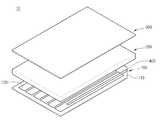
- FIG. 1is an exploded perspective view illustrating a solar cell module according to an embodiment.
- FIG. 2is a view showing a solar cell panel of the solar cell module according to the embodiment.
- FIG 3is a view showing a front surface of the solar cell module according to the embodiment.
- FIG. 4is a view illustrating a rear surface of the solar cell module according to the embodiment.
- FIG. 5is a side view of the portion A of FIG. 3.
- FIG. 6 to 11are views illustrating front and rear surfaces of a solar cell module according to various embodiments.
- each layer, region, pattern, or structuremay be “on” or “under” the substrate, each layer, region, pad, or pattern.
- Substrate formed inincludes all formed directly or through another layer. Criteria for the top / bottom or bottom / bottom of each layer will be described with reference to the drawings.
- each layer (film), region, pattern, or structuremay be modified for clarity and convenience of description, and thus do not necessarily reflect the actual size.
- FIG. 1is an exploded perspective view showing a solar cell module according to an embodiment
- Figure 2is a view showing a solar cell panel of the solar cell module according to the embodiment
- Figure 3is a front view of the solar cell module according to the embodiment 4 is a view illustrating a rear surface of a solar cell module according to an embodiment
- FIG. 5is a side view of a portion A of FIG. 3, and
- FIGS. 6 to 11are according to various embodiments. Figures showing the front and rear of the solar cell module.
- the solar cell module 10includes a solar cell panel 100, a buffer sheet 200, and a protective substrate 300.
- the solar cell panel 100may have a plate shape.
- the solar cell panel 100may include a support substrate 110 and a plurality of solar cells 120 disposed on the support substrate 110.
- the support substrate 110may be an insulator.
- the support substrate 110may be a glass substrate, a plastic substrate, or a metal substrate.
- the support substrate 110may be a soda lime glass substrate.
- a ceramic substratesuch as alumina, stainless steel, a flexible polymer, or the like may be used as the material of the support substrate 100.
- the support substrate 110may be transparent.
- the support substrate 110may be rigid or flexible.
- the support substrate 110may have at least two cutting regions CA formed at corners thereof.
- the support substrate 110may be formed by cutting two corner regions corresponding to each other to form a cutting region CA.
- the cutting area CAmay be formed in various shapes.
- the cutting area CAmay be formed in various shapes such as triangular, elliptical, or square.
- the solar cells 120may be, for example, a CIGS-based solar cell, a silicon-based solar cell, a fuel-sensitized solar cell, a III-IV compound semiconductor solar cell, or a III-V compound semiconductor solar cell.
- the solar cells 120may be arranged in a stripe shape. In addition, the solar cells 120 may be arranged in various forms such as a matrix form.
- the bus bar 400may be disposed on the solar cell panel 100.
- the bus bar 400may include a first bus bar 410 and a second bus bar 420.
- the first bus bar 410 and the second bus bar 420are connected to the solar cells 120.
- the first bus bar 410 and the second bus bar 420may be directly connected to the solar cells 120.
- the first bus bar 410 and the second bus bar 420may be electrically connected to the outermost solar cells 120, respectively.
- the first bus bar 410 and the second bus bar 420may include a conductive tape or a conductive paste.
- Examples of the material used as the first bus bar 410 and the second bus bar 420may include copper, silver, or aluminum.
- the bus bars 400are formed on the front and rear surfaces of the support substrate 111 and 112.
- the bus bars 400may extend along the edge of the support substrate front surface 111 to the edge of the support substrate rear surface 112.
- the first bus bar 410 and the second bus bar 420extend along the edge of the support substrate front surface 111 to the cutting area CA of the support substrate 100, and the cutting It may be formed extending to the edge of the back side 112 of the support substrate through the area (CA).
- first bus bar 410 and the second bus bar 420extend from the front surface 111 of the support substrate while passing through the cutting area CA to be formed on the back surface 112 of the support substrate. Can be.
- connection member 500may be disposed in the cutting area CA.
- connection member 500may be a junction box.
- connection member 500may be formed while surrounding the cutting area CA.
- the connection member 500may be formed while surrounding the support substrate 110 in the cutting area CA.
- connection member 500may surround the bus bars 400.
- the connection member 500may surround the first bus bar 410 and the second bus bar 420. That is, the connection member 500 may be disposed while surrounding the first bus bar 410 and the second bus bar 420 passing through the cutting area CA.
- the first bus bar 410 and the second bus bar 420may be connected to the cable 600 in the connection member 500.
- the first bus bar 410 and the second bus bar 420may be connected to the cable 600 by the junction part 700 in the connection member 500.
- the protective substrate 300is disposed on the solar cell panel 100.
- the protective substrate 300is disposed to face the solar cell panel 100.
- One side of the protective substrate 300may be disposed on the same plane as one side of the solar cell panel 100. That is, one side of the protective substrate 300 may not form a step with one side of the solar cell panel 100.
- the protective substrate 300is transparent and has high strength. Examples of the material used for the protective substrate 300 include tempered glass.
- the buffer sheet 200is interposed between the protective substrate 300 and the solar cell panel 100.
- the buffer sheet 200protects the solar cell panel 100 from an external physical shock.
- the buffer sheet 200prevents a direct collision between the protective substrate 300 and the solar cell panel 100.
- the buffer sheet 200may cover the solar cells 120.
- the buffer sheet 200may seal the solar cells 120 from the outside.
- the buffer sheet 200may protect the solar cells 120 from an external chemical shock.
- the buffer sheet 200may perform an anti-reflection function so that more light is incident on the solar cell panel 100.
- the buffer sheet 200may include an insulator.
- the buffer sheet 200may be made of an insulator.
- Examples of the material used as the buffer sheet 200include ethylene vinyl acetate resin (EVA resin). That is, the buffer sheet 200 is an insulating layer.
- EVA resinethylene vinyl acetate resin
- bus bars 400are formed on the front surface of the solar cell panel 100 and extend to the rear surface of the solar cell panel through a cutting area of a corner region.
- the bus bars 400may be wrapped by the connection member 500 in the corner region while extending from the front side to the rear side of the solar cell panel through the corner region. That is, the bus bars 400 extend from the front surface of the solar cell panel 100 to the rear surface of the solar cell panel 100 through the cutting region, and the bus bars 400 formed on the rear surface are connected members. It is wrapped by 500.
- connection member 500may be formed while surrounding side surfaces of the solar cell panel 100, the buffer sheet 200, and the protective substrate 300.
- the bus bars 400may be connected to the cable 600 by the junction part 700 in the connection member 500.
- the solar cell module according to the embodimentmay extend the bus bar from the front side to the rear side of the solar cell panel through a cutting region formed in the corner region of the support substrate.
- the bus barcan be formed by extending directly from the front side of the solar cell panel to the rear side.
- a through hole penetrating a support substrateis formed, and the bus bar extends to the rear side of the support substrate through the through hole.
- the durability of the support substrateis weakened by such a through hole, and as the solar panel is large in area, various problems such as deformation and deformation due to weakening of durability occur.
- the solar cell module according to the embodimentextends from the front side to the rear side without forming the through hole in the support substrate, thereby improving durability of the solar cell module.
- the solar cell module according to the embodimentcan prevent the bending or damage of the solar cell module.
- FIG. 6 to 11are views illustrating front and rear surfaces of a solar cell module according to various embodiments.
- 6 to 9are views illustrating a front surface of the solar cell module. 6 to 9, a cutting region is formed in a corner region of the solar cell panel, and the buffer sheet 200 and the protective substrate 300 are disposed covering the cutting region.
- connection member 500may be formed while surrounding the solar cell panel 100, the buffer sheet 200, and the protective substrate 300. That is, the connection member may extend from the rear side of the solar cell panel 100 and extend to the front side of the protective substrate. That is, the connection member may be formed on the front, side and back of the solar cell module.
- connection member 500may be formed in the same shape as the cut region or may be formed in a "-" shape.
- an edge of the connection member 500may be the same as the edge of the solar cell panel or protrude from the edge of the solar cell panel.
- connection member 500may be formed while surrounding the solar cell panel 100, the buffer sheet 200, and the protective substrate 300. That is, the connection member 500 may extend from the rear surface of the solar cell panel 100 to extend to the side surfaces of the solar cell panel 100, the buffer sheet 200, and the protective substrate 300. That is, the connection member may be formed only on the rear and side surfaces of the solar cell module.
- 10 and 11are views illustrating a rear surface of the solar cell module. That is, the back of the solar panel is a view showing. 10 and 11, the busbar is connected to a busbar at a connection member 500 formed in a cutting area, and the cable extends from the connection member to extend from the rear surface of the solar cell panel 100. Can be.
Landscapes
- Photovoltaic Devices (AREA)
- Life Sciences & Earth Sciences (AREA)
- Engineering & Computer Science (AREA)
- Sustainable Development (AREA)
- Sustainable Energy (AREA)
Abstract
Description
Translated fromKorean실시예는 태양전지 모듈에 관한 것이다.An embodiment relates to a solar cell module.
최근 석유나 석탄과 같은 기존 에너지 자원의 고갈이 예측되면서 이들을 대체할 대체 에너지에 대한 관심이 높아지면서, 태양 에너지로부터 전기 에너지를 생산하는 태양전지가 주목받고 있다.With the recent prediction of the depletion of existing energy resources such as oil and coal, increasing interest in alternative energy to replace them, solar cells that produce electrical energy from solar energy is attracting attention.
태양전지(Solar Cell 또는 Photovoltaic Cell)는 태양광을 직접 전기로 변환시키는 태양광발전의 핵심소자이다.Solar cells (Solar Cells or Photovoltaic Cells) are the key elements of photovoltaic power generation that convert sunlight directly into electricity.
예로서 반도체의 pn접합으로 만든 태양전지에 반도체의 금지대폭(Eg: Band-gap Energy)보다 큰 에너지를 가진 태양광이 입사되면 전자-정공 쌍이 생성되는데, 이들 전자-정공이 pn 접합부에 형성된 전기장에 의해 전자는 n층으로, 정공은 p층으로 모이게 됨에 따라 pn간에 기전력(광기전력: Photovoltage)이 발생하게 된다. 이때 양단의 전극에 부하를 연결하면 전류가 흐르게 되는 것이 동작원리이다.For example, when solar light having energy greater than the band-gap energy (Eg) is incident on a solar cell made of a pn junction of a semiconductor, electron-hole pairs are generated, and these electron-holes are formed in an electric field formed at a pn junction. As a result, electrons are gathered into the n-layer and holes are gathered into the p-layer, whereby electromotive force (photovoltage) is generated between pn. At this time, if the load is connected to the electrodes at both ends, the current flows.
태양전지에서 생선된 전류가 버스 바를 통해 정션박스와 연결되는데, 일반적으로 태양전지 패널의 전면에 버스바가 형성되고, 상기 패널의 홀을 형성하여 상기 홀을 통해 버스바를 패널의 후면에 버스바를 넘겨 정션박스와 연결하는 것이 일반적이다.The current drawn from the solar cell is connected to the junction box through a bus bar. In general, a bus bar is formed in the front of the solar panel, and the hole of the panel is formed to pass the bus bar to the back of the panel through the junction to the junction. It is common to connect with a box.
그러나, 패널에 홀을 형성함에 따라 패널의 내구성 및 신뢰성이 저하되고, 패널이 대면적화됨에 따라 이러한 문제점은 점점 커질 수 있다.However, as holes are formed in the panel, the durability and reliability of the panel may be degraded, and as the panel is enlarged, this problem may become larger.
이에 따라, 패널의 휨 또는 파손을 방지하기 위해 패널의 두께를 두껍게 하는 방법이 있으나, 이 경우, 태양전지 모듈의 무게가 증가하고 공정이 증가하는 문제점이 있다.Accordingly, there is a method of increasing the thickness of the panel to prevent bending or breakage of the panel, but in this case, there is a problem in that the weight of the solar cell module is increased and the process is increased.
따라서, 태양전지 패널에 버스바를 형성시 태양전지 패널의 내구성 및 신뢰성을 향상시킬 수 있는 새로운 구조의 태양전지 모듈의 필요성이 요구된다.Therefore, there is a need for a solar cell module having a new structure capable of improving durability and reliability of the solar cell panel when forming a bus bar in the solar cell panel.
실시예는 용이하게 제조될 수 있고, 향상된 신뢰성 및 내구성을 가지는 태양전지 모듈을 제공하고자 한다.Embodiments can be easily manufactured, and to provide a solar cell module having improved reliability and durability.
실시예에 따른 태양전지 모듈은, 지지기판; 상기 지지기판 상에 배치되는 복수 개의 태양전지 셀들; 상기 태양전지 셀들과 전기적으로 연결되는 적어도 하나의 버스바를 포함하고, 상기 지지기판은, 상기 지기기판은 모서리 영역에 형성되는 적어도 2개의 절단 영역을 포함하고, 상기 버스바는 상기 지지기판의 전면에서 상기 절단 영역을 통해 상기 지지기판의 후면으로 연장된다.Solar cell module according to an embodiment, the support substrate; A plurality of solar cells disposed on the support substrate; At least one bus bar electrically connected to the solar cells, wherein the support substrate includes at least two cutting regions formed at corner portions thereof, and the bus bar is disposed at a front surface of the support substrate. It extends through the cutting area to the back of the support substrate.
실시예에 따른 태양전지 모듈은, 지지기판의 모서리 영역에 형성되는 절단 영역을 통해 버스바를 태양전지 패널의 전면에서 후면으로 연장시킬 수 있다.The solar cell module according to the embodiment may extend the bus bar from the front side to the rear side of the solar cell panel through a cutting region formed in the corner region of the support substrate.
즉, 지지기판에 홀 등의 연결 통로를 형성하지 않고, 버스바를 바로 태양전지 패널의 전면에서 후면으로 연장하여 형성할 수 있다.That is, without forming a connection passage such as a hole in the support substrate, the bus bar can be formed by extending directly from the front side of the solar cell panel to the rear side.
종래에는 지지기판을 관통하는 관통홀을 형성하고, 이러한 관통홀을 통해 버스바를 지지기판의 후면으로 연장하였다. 그러나, 이러한 관통홀에 의해 지지기판의 내구성이 약해지는 문제점이 있었으며, 태양전지 패널이 대면적화됨에 따라 내구성 약화에 따른 파손 및 휨 등의 변형 등 다양한 문제점이 발생하였다.Conventionally, a through hole penetrating a support substrate is formed, and the bus bar extends to the rear side of the support substrate through the through hole. However, there is a problem in that the durability of the support substrate is weakened by such a through hole, and as the solar panel is large in area, various problems such as deformation and deformation due to weakening of durability occur.
이에 따라, 실시예에 따른 태양전지 모듈은 지지기판에 관통홀을 형성하지 않고, 바로 전면에서 후면으로 연장함으로써, 태양전지 모듈의 내구성을 향상시킬 수 있다.Accordingly, the solar cell module according to the embodiment extends from the front side to the rear side without forming the through hole in the support substrate, thereby improving durability of the solar cell module.
따라서, 실시예에 따른 태양전지 모듈은 태양전지 모듈의 휨 또는 파손 등을 방지할 수 있다.Therefore, the solar cell module according to the embodiment can prevent the bending or damage of the solar cell module.
도 1은 실시예에 따른 태양전지 모듈을 도시한 분해 사시도이다.1 is an exploded perspective view illustrating a solar cell module according to an embodiment.
도 2는 실시예에 따른 태양전지 모듈의 태양전지 패널을 도시한 도면이다.2 is a view showing a solar cell panel of the solar cell module according to the embodiment.
도 3은 실시예에 따른 태양전지 모듈의 전면을 도시한 도면이다.3 is a view showing a front surface of the solar cell module according to the embodiment.
도 4는 실시예에 따른 태양전지 모듈의 후면을 도시한 도면이다.4 is a view illustrating a rear surface of the solar cell module according to the embodiment.
도 5는 도 3의 A 부분의 측면도를 도시한 도면이다.5 is a side view of the portion A of FIG. 3.
도 6 내지 도 11은 다양한 실시예에 따른 태양전지 모듈의 전면 및 후면을 도시한 도면들이다.6 to 11 are views illustrating front and rear surfaces of a solar cell module according to various embodiments.
실시예들의 설명에 있어서, 각 층(막), 영역, 패턴 또는 구조물들이 기판, 각 층(막), 영역, 패드 또는 패턴들의 “상/위(on)”에 또는 “하/아래(under)”에 형성된다는 기재는, 직접(directly) 또는 다른 층을 개재하여 형성되는 것을 모두 포함한다. 각 층의 상/위 또는 하/아래에 대한 기준은 도면을 기준으로 설명한다.In the description of embodiments, each layer, region, pattern, or structure may be “on” or “under” the substrate, each layer, region, pad, or pattern. Substrate formed in ”includes all formed directly or through another layer. Criteria for the top / bottom or bottom / bottom of each layer will be described with reference to the drawings.
도면에서 각 층(막), 영역, 패턴 또는 구조물들의 두께나 크기는 설명의 명확성 및 편의를 위하여 변형될 수 있으므로, 실제 크기를 전적으로 반영하는 것은 아니다.In the drawings, the thickness or size of each layer (film), region, pattern, or structure may be modified for clarity and convenience of description, and thus do not necessarily reflect the actual size.
이하, 첨부한 도면을 참조하여 본 발명의 실시예를 상세하게 설명하면 다음과 같다.Hereinafter, exemplary embodiments of the present invention will be described in detail with reference to the accompanying drawings.
도 1 내지 도 11을 참조하여, 실시예에 따른 태양전지 모듈을 상세하게 설명한다. 도 1은 실시예에 따른 태양전지 모듈을 도시한 분해 사시도이고, 도 2는 실시예에 따른 태양전지 모듈의 태양전지 패널을 도시한 도면이며, 도 3은 실시예에 따른 태양전지 모듈의 전면을 도시한 도면이고, 도 4는 실시예에 따른 태양전지 모듈의 후면을 도시한 도면이며, 도 5는 도 3의 A 부분의 측면도를 도시한 도면이고, 도 6 내지 도 11은 다양한 실시예에 따른 태양전지 모듈의 전면 및 후면을 도시한 도면들이다.1 to 11, a solar cell module according to an embodiment will be described in detail. 1 is an exploded perspective view showing a solar cell module according to an embodiment, Figure 2 is a view showing a solar cell panel of the solar cell module according to the embodiment, Figure 3 is a front view of the solar cell module according to the embodiment 4 is a view illustrating a rear surface of a solar cell module according to an embodiment, FIG. 5 is a side view of a portion A of FIG. 3, and FIGS. 6 to 11 are according to various embodiments. Figures showing the front and rear of the solar cell module.
도 1 내지 도 11을 참조하면, 실시예에 따른 태양전지 모듈(10)은 태양전지 패널(100), 완충 시트(200) 및 보호기판(300)을 포함한다.1 to 11, the
상기 태양전지 패널(100)은 플레이트 형상을 가질 수 있다. 상기 태양전지 패널(100)은 지지기판(110) 및 상기 지지기판(110) 상에 배치되는 다수 개의 태양전지(120)들을 포함할 수 있다.The
상기 지지기판(110)은 절연체일 수 있다. 상기 지지기판(110)은 유리 기판, 플라스틱 기판 또는 금속 기판일 수 있다. 자세하게, 상기 지지기판(110)은 소다 라임 글래스(soda lime glass) 기판일 수 있다. 이와는 다르게, 상기 지지기판(100)의 재질로 알루미나와 같은 세라믹 기판, 스테인레스 스틸, 유연성이 있는 고분자 등이 사용될 수 있다. 상기 지지기판(110)은 투명할 수 있다. 상기 지지기판(110)은 리지드(rigid)하거나 또는 플렉서블(flexible)할 수 있다.The
도 2를 참조하면, 상기 지지기판(110)은 모서리에 적어도 2개의 절단 영역(CA)이 형성될 수 있다. 자세하게, 상기 지지기판(110)에는 서로 대응되는 2개의 모서리 영역이 절단되어 절단 영역(CA)이 형성될 수 있다.Referring to FIG. 2, the
상기 절단 영역(CA)은 다양한 형상으로 형성될 수 있다. 일례로, 상기 절단 영역(CA)은 삼각형, 타원형 또는 사각형 등 다양한 형상으로 형성될 수 있다.The cutting area CA may be formed in various shapes. For example, the cutting area CA may be formed in various shapes such as triangular, elliptical, or square.
상기 태양전지(120)들은 일례로, CIGS계 태양전지, 실리콘 계열 태양전지, 연료감응 계열 태양전지, Ⅲ-Ⅳ족 화합물 반도체 태양전지 또는 Ⅲ-Ⅴ족 화합물 반도체 태양전지일 수 있다.The
상기 태양전지(120)들은 스트라이프(stripe) 형태로 배치될 수 있다. 또한, 상기 태양전지(120)들은 매트릭스(matrix) 형태 등 다양한 형태로 배치될 수 있다.The
상기 태양전지 패널(100)에는 버스바(400)가 배치될 수 있다. 상기 버스바(400)는 제 1 버스바(410) 및 제 2 버스바(420)를 포함할 수 있다. 상기 제 1 버스바(410) 및 상기 제 2 버스바(420)는 상기 태양전지(120)들에 접속된다. 자세하게, 상기 제 1 버스바(410) 및 상기 제 2 버스바(420)는 상기 태양전지(120)들에 직접 접속될 수 있다. 더 자세하게, 상기 제 1 버스바(410) 및 상기 제 2 버스바(420)는 최외곽의 태양전지(120)들에 각각 전기적으로 접속될 수 있다.The
상기 제 1 버스바(410) 및 상기 제 2 버스바(420)는 도전 테이프 또는 도전성 페이스트를 포함할 수 있다. 상기 제 1 버스바(410) 및 상기 제 2 버스바(420)로 사용되는 물질의 예로는 구리, 은 또는 알루미늄 등을 들 수 있다.The first bus bar 410 and the second bus bar 420 may include a conductive tape or a conductive paste. Examples of the material used as the first bus bar 410 and the second bus bar 420 may include copper, silver, or aluminum.
도 3 및 도 4를 참조하면, 상기 버스바(400)들은 상기 지지기판 전면(111) 및 후면(112)에 형성된다. 자세하게 상기 버스바(400)들은 상기 지지기판 전면(111)의 가장자리를 따라 상기 지지기판 후면(112)의 가장자리로 연장될 수 있다. 더 자세하게, 상기 제 1 버스바(410) 및 상기 제 2 버스바(420)는 상기 지지기판 전면(111)의 가장자리를 따라서 상기 지지기판(100)의 절단 영역(CA)까지 연장되고, 상기 절단 영역(CA)을 통해 상기 지지기판 후면(112)의 가장자리로 연장되어 형성될 수 있다.3 and 4, the
이에 따라, 상기 제 1 버스바(410) 및 상기 제 2 버스바(420)는 상기 절단 영역(CA)을 통과하면서 상기 지지기판 전면(111)에서 연장되어 상기 지지기판 후면(112)에까지 형성될 수 있다.Accordingly, the first bus bar 410 and the second bus bar 420 extend from the front surface 111 of the support substrate while passing through the cutting area CA to be formed on the back surface 112 of the support substrate. Can be.
상기 절단 영역(CA)에는 접속 부재(500)가 배치될 수 있다. 일례로, 상기 접속 부재(500)는 정션 박스일 수 있다.The
상기 접속 부재(500)는 상기 절단 영역(CA)을 감싸면서 형성될 수 있다. 자세하게, 상기 접속 부재(500)는 상기 절단 영역(CA)에서 상기 지지기판(110)을 감싸면서 형성될 수 있다.The
상기 접속 부재(500)는 상기 버스바(400)들을 감쌀 수 있다. 자세하게, 상기 접속 부재(500)는 상기 제 1 버스바(410) 및 상기 제 2 버스바(420)를 감쌀 수 있다. 즉, 상기 접속 부재(500)는 상기 절단 영역(CA)을 통과하는 상기 제 1 버스바(410) 및 상기 제 2 버스바(420)를 감싸면서 배치될 수 있다.The
상기 제 1 버스바(410) 및 상기 제 2 버스바(420)는 상기 접속 부재(500)에서 케이블(600)과 연결될 수 있다. 자세하게, 상기 제 1 버스바(410) 및 상기 제 2 버스바(420)는 상기 접속 부재(500)에서 접합부(700)에 의해 상기 케이블(600)과 연결될 수 있다.The first bus bar 410 and the second bus bar 420 may be connected to the
상기 보호 기판(300)은 상기 태양전지 패널(100) 상에 배치된다. 더 자세하게, 상기 보호 기판(300)은 상기 태양전지 패널(100)에 대향되어 배치된다. 상기 보호 기판(300)의 일 측면은 상기 태양전지 패널(100)의 일 측면과 서로 동일한 평면에 배치될 수 있다. 즉, 상기 보호 기판(300)의 일 측면은 상기 태양전지 패널(100)의 일 측면과 단차를 형성하지 않을 수 있다.The
상기 보호 기판(300)은 투명하며, 높은 강도를 가진다. 상기 보호 기판(300)으로 사용되는 물질의 예로서는 강화 유리 등을 들 수 있다.The
상기 완충 시트(200)는 상기 보호 기판(300) 및 상기 태양전지 패널(100) 사이에 개재된다. 상기 완충 시트(200)는 상기 태양전지 패널(100)을 외부의 물리적인 충격으로부터 보호한다. 또한, 상기 완충 시트(200)는 상기 보호 기판(300) 및 상기 태양전지 패널(100) 사이의 직접적인 충돌을 방지한다.The
또한, 상기 완충 시트(200)는 상기 태양전지들(120)을 덮을 수 있다. 상기 완충 시트(200)는 상기 태양전지들(120)을 외부로부터 밀봉할 수 있다. 상기 완충 시트(200)는 상기 태양전지들(120)을 외부의 화학적인 충격으로부터 보호할 수 있다.In addition, the
상기 완충 시트(200)는 상기 태양전지 패널(100)에 보다 많은 광이 입사되도록 반사 방지 기능을 수행할 수 있다.The
상기 완충 시트(200)는 절연체를 포함할 수 있다. 더 자세하게, 상기 완충 시트(200)는 절연체로 이루어질 수 있다. 상기 완충 시트(200)로 사용되는 물질의 예로서는 에틸렌비닐아세테이트 수지(ethylenevinylacetate resin;EVA resin) 등을 들 수 있다. 즉, 상기 완충 시트(200)는 절연층이다.The
도 5는 도 3의 A 부분의 측면도를 도시한 도면이다. 도 4를 참조하면, 상기 버스바(400)들은 상기 태양전지 패널(100)의 전면에 형성되고, 모서리 영역의 절단 영역을 통해 태양전지 패널의 후면으로 연장된다.5 is a side view of the portion A of FIG. 3. Referring to FIG. 4, the bus bars 400 are formed on the front surface of the
상기 버스바(400)들은 상기 모서리 영역을 통해 태양전지 패널의 전면에서 후면으로 연장하면서 모서리 영역에서 접속 부재(500)에 의해 감싸질 수 있다. 즉, 상기 버스바(400)들은 상기 태양전지 패널(100)의 전면에서 상기 절단 영역을 통해 상기 태양전지 패널(100)의 후면으로 연장되면서 상기 후면에 형성되는 상기 버스바(400)들은 접속 부재(500)에 의해 감싸지게 된다.The bus bars 400 may be wrapped by the
상기 접속 부재(500)는 상기 태양전지 패널(100), 상기 완충 시트(200) 및 보호 기판(300)의 측면을 감싸면서 형성될 수 있다.The
상기 버스바(400)들은 상기 접속 부재(500)에서 접합부(700)에 의해 상기 케이블(600)과 연결될 수 있다.The bus bars 400 may be connected to the
실시예에 따른 태양전지 모듈은, 지지기판의 모서리 영역에 형성되는 절단 영역을 통해 버스바를 태양전지 패널의 전면에서 후면으로 연장시킬 수 있다.The solar cell module according to the embodiment may extend the bus bar from the front side to the rear side of the solar cell panel through a cutting region formed in the corner region of the support substrate.
즉, 지지기판에 홀 등의 연결 통로를 형성하지 않고, 버스바를 바로 태양전지 패널의 전면에서 후면으로 연장하여 형성할 수 있다.That is, without forming a connection passage such as a hole in the support substrate, the bus bar can be formed by extending directly from the front side of the solar cell panel to the rear side.
종래에는 지지기판을 관통하는 관통홀을 형성하고, 이러한 관통홀을 통해 버스바를 지지기판의 후면으로 연장하였다. 그러나, 이러한 관통홀에 의해 지지기판의 내구성이 약해지는 문제점이 있었으며, 태양전지 패널이 대면적화됨에 따라 내구성 약화에 따른 파손 및 휨 등의 변형 등 다양한 문제점이 발생하였다.Conventionally, a through hole penetrating a support substrate is formed, and the bus bar extends to the rear side of the support substrate through the through hole. However, there is a problem in that the durability of the support substrate is weakened by such a through hole, and as the solar panel is large in area, various problems such as deformation and deformation due to weakening of durability occur.
이에 따라, 실시예에 따른 태양전지 모듈은 지지기판에 관통홀을 형성하지 않고, 바로 전면에서 후면으로 연장함으로써, 태양전지 모듈의 내구성을 향상시킬 수 있다.Accordingly, the solar cell module according to the embodiment extends from the front side to the rear side without forming the through hole in the support substrate, thereby improving durability of the solar cell module.
따라서, 실시예에 따른 태양전지 모듈은 태양전지 모듈의 휨 또는 파손 등을 방지할 수 있다.Therefore, the solar cell module according to the embodiment can prevent the bending or damage of the solar cell module.
도 6 내지 도 11은 다양한 실시예에 따른 태양전지 모듈의 전면 및 후면을 도시한 도면들이다.6 to 11 are views illustrating front and rear surfaces of a solar cell module according to various embodiments.
도 6 내지 도 9는 태양전지 모듈의 전면을 도시한 도면들이다. 도 6 내지 도 9를 참조하면, 상기 태양전지 패널의 모서리 영역에는 절단 영역이 형성되고, 완충 시트(200) 및 보호기판(300)이 상기 절단 영역을 덮으면서 배치된다.6 to 9 are views illustrating a front surface of the solar cell module. 6 to 9, a cutting region is formed in a corner region of the solar cell panel, and the
도 6 내지 도 8을 참조하면, 태양전지 패널(100), 완충 시트(200) 및 보호기판(300)을 감싸면서 접속 부재(500)가 형성될 수 있다. 즉, 상기 접속 부재는 상기 태양전지 패널(100)의 후면에서 연장되어, 상기 보호기판의 전면까지 연장되어 형성될 수 있다. 즉, 상기 접속 부재는 상기 태양전지 모듈의 전면, 측면 및 후면에형성될 수 있다.6 to 8, the
상기 접속 부재(500)는 상기 절단 영역과 동일한 형상으로 형성되거나 또는 "ㄱ"자 형상으로 형성될 수 있다. 또한, 상기 접속 부재(500)의 가장자리는 상기 태양전지 패널의 가장자리와 동일하거나 또는 태양전지 패널의 가장자리에서 돌출되어 형성될 수 있다.The
또는, 도 9를 참조하면, 태양전지 패널(100), 완충 시트(200) 및 보호기판(300)을 감싸면서 접속 부재(500)가 형성될 수 있다. 즉, 상기 접속 부재(500)는 상기 태양전지 패널(100)의 후면에서 연장되어, 태양전지 패널(100), 완충 시트(200) 및 보호기판(300)의 측면까지 연장되어 형성될 수 있다. 즉, 상기 접속 부재는 상기 태양전지 모듈의 후면 및 측면에만 형성될 수 있다.Alternatively, referring to FIG. 9, the
도 10 및 도 11은 태양전지 모듈의 후면을 도시한 도면들이다. 즉, 태양전지 패널의 후면을 도시한 도면들이다. 도 10 및 도 11을 참조하면, 상기 버스바는 절단 영역에 형성된 접속 부재(500)에서 버스바가 케이블과 연결되고, 상기 케이블은 상기 접속 부재에서 연장되어 상기 태양전지 패널(100)의 후면에서 연장될 수 있다.10 and 11 are views illustrating a rear surface of the solar cell module. That is, the back of the solar panel is a view showing. 10 and 11, the busbar is connected to a busbar at a
상술한 실시예에 설명된 특징, 구조, 효과 등은 본 발명의 적어도 하나의 실시예에 포함되며, 반드시 하나의 실시예에만 한정되는 것은 아니다. 나아가, 각 실시예에서 예시된 특징, 구조, 효과 등은 실시예들이 속하는 분야의 통상의 지식을 가지는 자에 의하여 다른 실시예들에 대해서도 조합 또는 변형되어 실시 가능하다. 따라서 이러한 조합과 변형에 관계된 내용들은 본 발명의 범위에 포함되는 것으로 해석되어야 할 것이다.Features, structures, effects, and the like described in the above embodiments are included in at least one embodiment of the present invention, and are not necessarily limited to only one embodiment. In addition, the features, structures, effects, and the like illustrated in the embodiments may be combined or modified with respect to other embodiments by those skilled in the art to which the embodiments belong. Therefore, contents related to such combinations and modifications should be construed as being included in the scope of the present invention.
또한, 이상에서 실시예들을 중심으로 설명하였으나 이는 단지 예시일 뿐 본 발명을 한정하는 것이 아니며, 본 발명이 속하는 분야의 통상의 지식을 가진 자라면 본 실시예의 본질적인 특성을 벗어나지 않는 범위에서 이상에 예시되지 않은 여러 가지의 변형과 응용이 가능함을 알 수 있을 것이다. 예를 들어, 실시예들에 구체적으로 나타난 각 구성 요소는 변형하여 실시할 수 있는 것이다. 그리고 이러한 변형과 응용에 관계된 차이점들은 첨부한 청구 범위에서 규정하는 본 발명의 범위에 포함되는 것으로 해석되어야 할 것이다.In addition, the above description has been made with reference to the embodiments, which are merely examples and are not intended to limit the present invention, and those skilled in the art to which the present invention pertains may be illustrated as above without departing from the essential characteristics of the present embodiments. It will be appreciated that various modifications and applications are possible. For example, each component specifically shown in the embodiments may be modified. And differences relating to such modifications and applications will have to be construed as being included in the scope of the invention defined in the appended claims.
Claims (15)
Translated fromKoreanPriority Applications (2)
| Application Number | Priority Date | Filing Date | Title |
|---|---|---|---|
| CN201480051413.0ACN105556683B (en) | 2013-09-17 | 2014-09-17 | Solar module |
| US15/022,771US9954484B2 (en) | 2013-09-17 | 2014-09-17 | Solar battery module |
Applications Claiming Priority (2)
| Application Number | Priority Date | Filing Date | Title |
|---|---|---|---|
| KR10-2013-0111900 | 2013-09-17 | ||
| KR1020130111900AKR20150031975A (en) | 2013-09-17 | 2013-09-17 | Solar cell module |
Publications (1)
| Publication Number | Publication Date |
|---|---|
| WO2015041463A1true WO2015041463A1 (en) | 2015-03-26 |
Family
ID=52689072
Family Applications (1)
| Application Number | Title | Priority Date | Filing Date |
|---|---|---|---|
| PCT/KR2014/008658WO2015041463A1 (en) | 2013-09-17 | 2014-09-17 | Solar battery module |
Country Status (4)
| Country | Link |
|---|---|
| US (1) | US9954484B2 (en) |
| KR (1) | KR20150031975A (en) |
| CN (1) | CN105556683B (en) |
| WO (1) | WO2015041463A1 (en) |
Families Citing this family (3)
| Publication number | Priority date | Publication date | Assignee | Title |
|---|---|---|---|---|
| US20180006602A1 (en) | 2016-07-01 | 2018-01-04 | Sunpower Corporation | Photovoltaic module having an external electrical connector |
| KR20190085789A (en)* | 2018-01-11 | 2019-07-19 | 엘지전자 주식회사 | Compound semiconductor solar cell and module thereof |
| DE102020134996A1 (en)* | 2020-12-29 | 2022-06-30 | Heliatek Gmbh | Photovoltaic element having at least one photovoltaic cell and at least one folded busbar |
Citations (5)
| Publication number | Priority date | Publication date | Assignee | Title |
|---|---|---|---|---|
| US20050011551A1 (en)* | 2003-07-14 | 2005-01-20 | Simburger Edward J. | Thin film solar cell electrical contacts |
| US20100218805A1 (en)* | 2007-02-15 | 2010-09-02 | The Australian National University | Substrate, an assembly process, and an assembly apparatus |
| US20110155209A1 (en)* | 2008-08-29 | 2011-06-30 | Odersun Ag | Thin film solar cell and photovoltaic string assembly |
| US20110308562A1 (en)* | 2010-06-22 | 2011-12-22 | Miasole | Photovoltaic module electrical connectors |
| KR20120045633A (en)* | 2010-10-29 | 2012-05-09 | 엘지이노텍 주식회사 | Solar cell apparatus and method of fabricating the same |
Family Cites Families (5)
| Publication number | Priority date | Publication date | Assignee | Title |
|---|---|---|---|---|
| US20100043862A1 (en)* | 2008-05-15 | 2010-02-25 | Steven Thomas Croft | Solar Panel Interconnection System |
| DE102010016975A1 (en) | 2009-05-18 | 2011-01-05 | Solarion Ag | Arrangement and interconnection, and method for interconnecting planar solar cells |
| US20110271999A1 (en)* | 2010-05-05 | 2011-11-10 | Cogenra Solar, Inc. | Receiver for concentrating photovoltaic-thermal system |
| CN102820359A (en) | 2011-06-08 | 2012-12-12 | 茂迪股份有限公司 | Solar module with grating and manufacturing method thereof |
| US20130092216A1 (en)* | 2011-10-17 | 2013-04-18 | Array Power Inc. | Solar Cell Module Junction Box |
- 2013
- 2013-09-17KRKR1020130111900Apatent/KR20150031975A/ennot_activeCeased
- 2014
- 2014-09-17CNCN201480051413.0Apatent/CN105556683B/ennot_activeExpired - Fee Related
- 2014-09-17WOPCT/KR2014/008658patent/WO2015041463A1/enactiveApplication Filing
- 2014-09-17USUS15/022,771patent/US9954484B2/ennot_activeExpired - Fee Related
Patent Citations (5)
| Publication number | Priority date | Publication date | Assignee | Title |
|---|---|---|---|---|
| US20050011551A1 (en)* | 2003-07-14 | 2005-01-20 | Simburger Edward J. | Thin film solar cell electrical contacts |
| US20100218805A1 (en)* | 2007-02-15 | 2010-09-02 | The Australian National University | Substrate, an assembly process, and an assembly apparatus |
| US20110155209A1 (en)* | 2008-08-29 | 2011-06-30 | Odersun Ag | Thin film solar cell and photovoltaic string assembly |
| US20110308562A1 (en)* | 2010-06-22 | 2011-12-22 | Miasole | Photovoltaic module electrical connectors |
| KR20120045633A (en)* | 2010-10-29 | 2012-05-09 | 엘지이노텍 주식회사 | Solar cell apparatus and method of fabricating the same |
Also Published As
| Publication number | Publication date |
|---|---|
| US20160233345A1 (en) | 2016-08-11 |
| KR20150031975A (en) | 2015-03-25 |
| CN105556683B (en) | 2017-11-14 |
| CN105556683A (en) | 2016-05-04 |
| US9954484B2 (en) | 2018-04-24 |
Similar Documents
| Publication | Publication Date | Title |
|---|---|---|
| WO2015041437A1 (en) | Solar battery module | |
| WO2011037373A2 (en) | Solar cell module and method of manufacturing the same | |
| WO2011078630A2 (en) | Solar power generating apparatus | |
| WO2011037374A2 (en) | Solar cell module and method of manufacturing the same | |
| WO2013133634A1 (en) | Solar cell module | |
| WO2013100498A1 (en) | Connector and solar cell module comprising the same | |
| WO2015056934A1 (en) | Solar cell module | |
| EP2747151A2 (en) | Apparatus for photovoltaic power generation | |
| WO2013162302A1 (en) | Photovoltaic apparatus | |
| WO2013058457A1 (en) | Flexible solar cell apparatus and method of fabricating the same | |
| WO2013077674A1 (en) | Solar cell module and method of fabricating the same | |
| WO2015041463A1 (en) | Solar battery module | |
| WO2012046933A1 (en) | Solar photovoltaic device and a conveying device comprising the same | |
| WO2013058460A1 (en) | Flexible frame for solar cell module apparatus and solar cell module apparatus using the same | |
| WO2013055006A1 (en) | Solar cell module and method of fabricating the same | |
| WO2013066031A1 (en) | Solar cell module and method of fabricating the same | |
| WO2015053565A1 (en) | Solar cell module | |
| WO2013151388A1 (en) | Solar cell module | |
| WO2013081357A1 (en) | Solar cell module and method of fabricating the same | |
| WO2011071226A1 (en) | Solar cell module | |
| WO2013077673A1 (en) | Solar cell apparatus | |
| WO2013081356A1 (en) | Solar cell module and method of fabricating the same | |
| WO2013073863A1 (en) | Solar cell module | |
| WO2013180491A1 (en) | Solar cell module and manufacturing method thereof | |
| WO2013081354A1 (en) | Solar cell module |
Legal Events
| Date | Code | Title | Description |
|---|---|---|---|
| WWE | Wipo information: entry into national phase | Ref document number:201480051413.0 Country of ref document:CN | |
| 121 | Ep: the epo has been informed by wipo that ep was designated in this application | Ref document number:14846240 Country of ref document:EP Kind code of ref document:A1 | |
| NENP | Non-entry into the national phase | Ref country code:DE | |
| WWE | Wipo information: entry into national phase | Ref document number:15022771 Country of ref document:US | |
| 122 | Ep: pct application non-entry in european phase | Ref document number:14846240 Country of ref document:EP Kind code of ref document:A1 |