WO2014208538A1 - Communication system, apparatus, method and program - Google Patents
Communication system, apparatus, method and programDownload PDFInfo
- Publication number
- WO2014208538A1 WO2014208538A1PCT/JP2014/066668JP2014066668WWO2014208538A1WO 2014208538 A1WO2014208538 A1WO 2014208538A1JP 2014066668 WJP2014066668 WJP 2014066668WWO 2014208538 A1WO2014208538 A1WO 2014208538A1
- Authority
- WO
- WIPO (PCT)
- Prior art keywords
- packet
- communication
- network
- switch
- virtual machine
- Prior art date
Links
Images


Classifications
- G—PHYSICS
- G06—COMPUTING OR CALCULATING; COUNTING
- G06F—ELECTRIC DIGITAL DATA PROCESSING
- G06F9/00—Arrangements for program control, e.g. control units
- G06F9/06—Arrangements for program control, e.g. control units using stored programs, i.e. using an internal store of processing equipment to receive or retain programs
- G06F9/44—Arrangements for executing specific programs
- G06F9/455—Emulation; Interpretation; Software simulation, e.g. virtualisation or emulation of application or operating system execution engines
- G06F9/45533—Hypervisors; Virtual machine monitors
- G06F9/45558—Hypervisor-specific management and integration aspects
- H—ELECTRICITY
- H04—ELECTRIC COMMUNICATION TECHNIQUE
- H04L—TRANSMISSION OF DIGITAL INFORMATION, e.g. TELEGRAPHIC COMMUNICATION
- H04L12/00—Data switching networks
- H04L12/28—Data switching networks characterised by path configuration, e.g. LAN [Local Area Networks] or WAN [Wide Area Networks]
- H04L12/46—Interconnection of networks
- H04L12/4604—LAN interconnection over a backbone network, e.g. Internet, Frame Relay
- H04L12/462—LAN interconnection over a bridge based backbone
- H04L12/4625—Single bridge functionality, e.g. connection of two networks over a single bridge
- H—ELECTRICITY
- H04—ELECTRIC COMMUNICATION TECHNIQUE
- H04L—TRANSMISSION OF DIGITAL INFORMATION, e.g. TELEGRAPHIC COMMUNICATION
- H04L12/00—Data switching networks
- H04L12/28—Data switching networks characterised by path configuration, e.g. LAN [Local Area Networks] or WAN [Wide Area Networks]
- H04L12/46—Interconnection of networks
- H04L12/4641—Virtual LANs, VLANs, e.g. virtual private networks [VPN]
- H—ELECTRICITY
- H04—ELECTRIC COMMUNICATION TECHNIQUE
- H04L—TRANSMISSION OF DIGITAL INFORMATION, e.g. TELEGRAPHIC COMMUNICATION
- H04L45/00—Routing or path finding of packets in data switching networks
- H04L45/16—Multipoint routing
- H—ELECTRICITY
- H04—ELECTRIC COMMUNICATION TECHNIQUE
- H04L—TRANSMISSION OF DIGITAL INFORMATION, e.g. TELEGRAPHIC COMMUNICATION
- H04L45/00—Routing or path finding of packets in data switching networks
- H04L45/24—Multipath
- H—ELECTRICITY
- H04—ELECTRIC COMMUNICATION TECHNIQUE
- H04L—TRANSMISSION OF DIGITAL INFORMATION, e.g. TELEGRAPHIC COMMUNICATION
- H04L45/00—Routing or path finding of packets in data switching networks
- H04L45/58—Association of routers
- H04L45/586—Association of routers of virtual routers
- H—ELECTRICITY
- H04—ELECTRIC COMMUNICATION TECHNIQUE
- H04L—TRANSMISSION OF DIGITAL INFORMATION, e.g. TELEGRAPHIC COMMUNICATION
- H04L45/00—Routing or path finding of packets in data switching networks
- H04L45/64—Routing or path finding of packets in data switching networks using an overlay routing layer
- H—ELECTRICITY
- H04—ELECTRIC COMMUNICATION TECHNIQUE
- H04L—TRANSMISSION OF DIGITAL INFORMATION, e.g. TELEGRAPHIC COMMUNICATION
- H04L45/00—Routing or path finding of packets in data switching networks
- H04L45/74—Address processing for routing
- H04L45/745—Address table lookup; Address filtering
- H—ELECTRICITY
- H04—ELECTRIC COMMUNICATION TECHNIQUE
- H04L—TRANSMISSION OF DIGITAL INFORMATION, e.g. TELEGRAPHIC COMMUNICATION
- H04L67/00—Network arrangements or protocols for supporting network services or applications
- H04L67/01—Protocols
- H04L67/10—Protocols in which an application is distributed across nodes in the network
- H04L67/1001—Protocols in which an application is distributed across nodes in the network for accessing one among a plurality of replicated servers
- H04L67/1004—Server selection for load balancing
- H04L67/1017—Server selection for load balancing based on a round robin mechanism
- H—ELECTRICITY
- H04—ELECTRIC COMMUNICATION TECHNIQUE
- H04L—TRANSMISSION OF DIGITAL INFORMATION, e.g. TELEGRAPHIC COMMUNICATION
- H04L67/00—Network arrangements or protocols for supporting network services or applications
- H04L67/50—Network services
- H04L67/56—Provisioning of proxy services
- H04L67/563—Data redirection of data network streams
- H—ELECTRICITY
- H04—ELECTRIC COMMUNICATION TECHNIQUE
- H04L—TRANSMISSION OF DIGITAL INFORMATION, e.g. TELEGRAPHIC COMMUNICATION
- H04L67/00—Network arrangements or protocols for supporting network services or applications
- H04L67/50—Network services
- H04L67/56—Provisioning of proxy services
- H04L67/566—Grouping or aggregating service requests, e.g. for unified processing
- G—PHYSICS
- G06—COMPUTING OR CALCULATING; COUNTING
- G06F—ELECTRIC DIGITAL DATA PROCESSING
- G06F9/00—Arrangements for program control, e.g. control units
- G06F9/06—Arrangements for program control, e.g. control units using stored programs, i.e. using an internal store of processing equipment to receive or retain programs
- G06F9/44—Arrangements for executing specific programs
- G06F9/455—Emulation; Interpretation; Software simulation, e.g. virtualisation or emulation of application or operating system execution engines
- G06F9/45533—Hypervisors; Virtual machine monitors
- G06F9/45558—Hypervisor-specific management and integration aspects
- G06F2009/45595—Network integration; Enabling network access in virtual machine instances
Definitions
- the present inventionis based on the priority claim of Japanese patent application: Japanese Patent Application No. 2013-133050 (filed on June 25, 2013), the entire contents of which are incorporated herein by reference. Shall.
- the present inventionrelates to a communication system, an apparatus, a method, and a program.
- Various appliances included in the network of telecommunications carrierssuch as MME (Mobility Management Entity), S-GW (Serving-Gateway), P-GW (Packet Data Network-Gateway), router, large scale NAT (LSN: Large Scale Network address translation), HLR (Home Location Register), RNC (Radio Netwok Controller) / eNodeB, firewall, authentication server, and the like are each configured with dedicated devices.
- MMEMobility Management Entity
- S-GWServer-Gateway
- P-GWPacket Data Network-Gateway
- routerlarge scale NAT (LSN: Large Scale Network address translation)
- HLRHome Location Register
- RNCRadio Netwok Controller
- NFVaims to reduce equipment costs and operational costs by implementing network devices, etc., mounted on these dedicated devices, for example, with server virtualization technology using a general-purpose server. Moreover, it is possible to improve fault tolerance by adding resources to an increase in communication load such as a control signal.
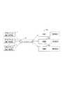
- FIG. 1is a diagram schematically illustrating a carrier network (carrier network). Since this provider network is also an example of a network to which an embodiment described later is applied, its related technology will be described.
- FIG. 1schematically shows an example of connection by PPPoE (Point to Point Protocol over Ethernet (registered trademark)).
- PPPoEPoint to Point Protocol over Ethernet
- Non-Patent Document 1is referred to.
- the terminals 11 1 to 11 n in the subscriber premises 1are connected to a DSLAM (Digital Subscriber Line Access Multiplexer) 21 in the station building via a router 10, an ADSL (Asymmetric Digital Subscriber Line) modem 12, and an ADSL line 15.
- a BAS (Broadband Access Server) 20is an access server having a router function, and performs switching of the provider 30 and bandwidth management in accordance with connection authentication from the user and a provider identifier.
- the DSLAM 21is a layer 2 (L2) concentrator that bundles a plurality of ADSL lines into one.
- L2layer 2
- the BASmay be a BRAS (Broadband Remote Access Server).
- BRASBroadband Remote Access Server
- FTTHFiber To The Home
- a modemis not required and the router is a FTTH router.
- the router 10in the subscriber premises and the access server BAS 20 are bridge-connected to perform PPP (Point-to-Point-Protocol) connection.
- the BAS 20recognizes which provider (ISP: InternetIService Provider) is connected to, for example, a user account of “user ID @ provider identifier”, authenticates the user, and transfers user data to a connection point with the provider.
- ISPInternetIService Provider
- From the router 10 to the DSLAM 21is tunneled by PPPoE, and between the DSLAM 21 and the BAS 20 is tunneled by L2TP (Layer 2 Tunneling Protocol).
- L2TPLayer 2 Tunneling Protocol
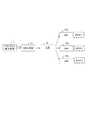
- FIG. 2is a diagram for explaining the sequence operation of the PPPoE discovery stage.
- the PPPoE sessionis started by transmitting a PADI (PPPoE Active Discovery Initiation) packet from the router side which is a PPPoE client.
- the PADI packetis a broadcast packet whose destination MAC address (48 bits) is all 1 as exemplified in the header format in FIG.
- the BASWhen the BAS receives a serviceable PADI, the BAS returns a response packet PADO (PPPoE Active Discovery Offer) to the router (10 in Fig. 1) that is the host that sent the PADI.
- PADOPPPoE Active Discovery Offer
- the routertransmits a PADR (PPPoE Active Discovery Request) by unicast to the BAS that is the source of the received PADO, and then starts a session with the BAS that sent the PADR.
- PADRPPPoE Active Discovery Request
- network appliance virtualizationis realized by mounting a network appliance of a communication carrier on a virtual machine on a virtualization platform of a general-purpose server.
- FIG. 3is a diagram illustrating a configuration (prototype) obtained by virtualizing BRAS / BAS, for example.
- the BRAS function(BRAS 1 , 2 , 3 ) is realized by software operating on virtual machines (VMs) 230 1 , 230 2 , 230 3 on the virtualization infrastructure of the server.
- VMsvirtual machines
- BRAS / BASwhen BRAS / BAS is virtualized, a general-purpose device (virtual machine on a general-purpose server) is used instead of a dedicated device that executes only the BRAS / BAS function. Compared with the case of using, the processing performance of BRAS / BAS is lowered.
- BRAS / BASwhen BRAS / BAS is virtualized, it is necessary to distribute the load of the number of sessions (number of clients) accommodated by each BRAS / BAS in consideration of the processing performance of BRAS / BAS.
- a sessionis established by a broadcast packet called PADI. That is, when a client sends PADI and a plurality of BRAS / BAS responds, the client selects one of them and establishes a session.
- an object of the present inventionis to provide a system, apparatus, method, and program that enable load distribution over the entire network system.
- a communication control apparatusin a communication system in which a virtual machine executes a communication function of a hardware device used in a communication network, the communication function and the communication function.
- a first means for selecting, from a plurality of the virtual machines, transfer destinations of packets to be transferred toward a plurality of paths to establish a session; and a second means for transferring the packets to the selected virtual machinesA communication control device is provided.
- viewpoint 2there is a communication control method in a communication system in which a virtual machine executes a communication function of a hardware device used in a communication network, and a plurality of methods are used to establish a communication session with the communication function. There is provided a communication control method for selecting a transfer destination of a packet to be transferred toward the path from a plurality of the virtual machines and transferring the packets to the selected virtual machine.
- a communication control device in a communication systemin which a virtual machine executes a communication function of a hardware device used in a communication network, a plurality of communication functions and a communication session are established in order to establish a communication session.
- a communication control programfor executing a process of selecting a transfer destination of a packet transferred toward a path from a plurality of the virtual machines and a process of transferring the packets to the selected virtual machine.
- a computer-readable mediumsemiconductor memory, magnetic / optical disk, etc. on which the program of viewpoint 3 is recorded is provided.
- a communication control device of a communication systemin which a virtual machine executes a communication function of a hardware device used in a communication network, and a plurality of paths are established to establish a communication session with the communication function.
- a communication control deviceis provided.
- a communication device in a communication systemin which a virtual machine executes a communication function of a hardware device used in a communication network, and is directed to a plurality of paths in order to establish a communication session with the communication function
- a communication apparatuscomprising: means for identifying the packets transferred in the above; and means for aggregating the identified packets in an apparatus for forwarding the packets to a virtual machine selected from a plurality of the virtual machines.
- an information processing apparatusin which a virtual machine that executes a communication function of a hardware device used in a communication network is arranged, and means for operating a virtual switch having a network switch function And the virtual switch has transfer means for transferring a packet transferred toward a plurality of paths to establish a communication session with the communication function to a virtual machine selected from the plurality of virtual machines.
- a processing deviceis provided.
- At least one forwarding destinationis selected for the packet, and the packet is forwarded to the selected forwarding destination.
- a communication system(method, program) provided with means (process, process) is provided.
- FIG. 1It is a schematic diagram which illustrates a PPPoE connection. It is a figure explaining a PPPoE discovery stage. It is a figure explaining a prototype example. It is a figure explaining embodiment. It is a figure which illustrates virtualization of the network function in Embodiment 1 of this invention. It is a figure which illustrates the structure of OFC of Embodiment 1 of this invention. It is explanatory drawing which illustrates typically operation
- Embodiment 6 of this inventiontypically. It is a figure which illustrates the structure of OFC of Embodiment 6 of this invention. It is a figure which illustrates the sequence operation
- a communication control apparatus (500) in a communication system in which a virtual machine executes a communication function of a hardware device used in a communication networkincludes the communication function and In order to establish a communication session, a transfer destination of a packet (503) transferred toward a plurality of paths (504 1 to 504 n , where n is a predetermined positive integer of 2 or more) is set as a plurality of virtual machines ( VM: 505 1 to 505 n ), and a second means (502) for transferring the packet (503) to the selected virtual machine (VM).
- the first means (501)may select a transfer destination of the packets collected in the communication control device (500) from a plurality of the virtual machines.
- the first means(501 or corresponding to, for example, the OFC 200 in FIG. 5) is a network switch (not shown in FIG. 30, for example, FIG. 5) having a function of consolidating the packets (503) in the communication control device (500).
- the OVS 220may receive the packet, and a transfer destination of the received packet may be selected from the plurality of virtual machines.
- the first means (501)may select the packet transfer destination so that the packet transfer destination is distributed among the plurality of virtual machines.
- the first means (501)may select a transfer destination of the packet according to an operation state of the plurality of virtual machines.
- the first means (501)receives the packet from a network switch (not shown in FIG. 30, for example, OVS 220 in FIG. 5) that operates in response to an instruction from the communication control device (500).
- a packet transfer destinationmay be selected from a plurality of virtual machines.
- the first means (501)receives an instruction request regarding the packet from the network switch (for example, the OVS 220 in FIG. 5), and receives the request. Accordingly, the transfer destination of the packet may be selected from a plurality of the virtual machines.
- the first means (501)receives the packet transferred from the network switch according to an instruction from the communication control device (500), and selects a transfer destination of the packet from a plurality of virtual switches. It may be.
- a communication control device (600) of a communication system in which a virtual machine executes a communication function of a hardware device used in a communication networkis communicated with the communication function.
- a transfer destination of a packet (603) transferred toward a plurality of paths (605 1 to 605 n , where n is a predetermined positive integer equal to or greater than 2)is defined as a plurality of virtual machines (VM : 606 1 to 606 n ) and a second means for instructing the network switch (604) to transfer the packet (603) to the selected virtual machine (VM) Means (602).
- a communication device in a communication system in which a virtual machine executes a communication function of a hardware device used in a communication networkhas a plurality of paths for establishing a communication session with the communication function. And means for aggregating the identified packets in a device for transferring the packets to a selected virtual machine from a plurality of virtual machines.
- At least one packet forwarded to a plurality of routes(route 1 to route n, where n is a predetermined positive integer equal to or greater than 2) is provided.
- means for narrowing down transfer destinationsselecting at least one transfer destination (path m, 1 ⁇ m ⁇ n) for the packet and selectively transferring the packet to the selected transfer destination (700).
- an information processing apparatusin which a virtual machine that executes a communication function of a hardware device used in a communication network is arranged has a function of a network switch.
- the transfer means of the virtual switch(for example, 220 in FIG. 5) transfers the packet transferred toward a plurality of paths to establish a communication session with the communication function to a communication control unit (200 in FIG. 5). Then, the packet is transferred to the virtual machine selected by the communication control unit (200 in FIG. 5).
- the means for narrowing down forwarding destinationsaggregates packets broadcast on the network, and unicasts the packets to the selected forwarding destination. You may make it include the node (26 of FIG. 4) transferred by the cast.
- the control devicereceives a notification (402 in FIG. 25) from a switch that has received a packet forwarded toward a plurality of routes, and among the plurality of switches, And means (401 in FIG. 25) for selecting at least one port (PORT) for transferring the packet of the predetermined format or a switch (SW) corresponding to the port.
- PORTport
- SWswitch
- the switch(OVS in FIG. 5, OFS in FIG. 18) is input according to the processing rules set by the control device (OFC in FIG. 5, OFC in FIG. 18). Packet transfer is processed, and the control device (OFC in FIG. 5, OFC in FIG. 18) sets the processing rule relating to packet transfer in the switch.
- the switchincludes a line concentrator (DSLAM in FIG. 11) that collects a plurality of lines, and the line concentrator controls the switch controlled by the controller (27 in FIG. 11). And the packet may be transferred to the selected transfer destination. Or it is good also as a structure provided with the load distribution apparatus (LB of FIG. 13) which determines the transfer destination of the said packet.
- DSLAMline concentrator
- LBload distribution apparatus
- a line concentratorDSLAM in FIGS. 15 and 17
- LBload balancer
- the control device(OFC in FIG. 18) is connected to a plurality of the switches (OFS1, OFS2, OFS3 in FIG. 18), and the plurality of switches are connected to the control device (OFC in FIG. 18) when receiving a broadcast packet. On the other hand, broadcast packet reception is notified.
- the control device(OFC in FIG. 18) may start a timer when it first receives a broadcast packet reception notification from the switch, and may select at least one port or switch when a timeout occurs.
- each of the plurality of switches(FIG. 5 OVS1, OVS2, OVS3) is connected to one or a plurality of network function units (VM11 to VM13, VM21 to VM23, VM31 to VM33), and the control device (FIG. 5).
- OFCis connected to a plurality of network function units (VM11 to VM13, VM21 to VM23, VM31 to VM33) connected to a plurality of the switches (OVS1, OVS2 and OVS3 in FIG.
- broadcast packets from the switches A port that receives a notification of receptionselects at least one of the network function units based on loads of the plurality of network function units (VM11 to VM13, VM21 to VM23, VM31 to VM33), and connects to the selected network function unit For a switch having And it instructs the forwarding of the broadcast packet from.
- the network function units(VM11 to VM13, VM21 to VM23, VM31 to VM33) are virtual machines virtualized on a server virtual infrastructure (VMM).
- VMMserver virtual infrastructure
- a switchwhen receiving a packet in a transfer format (for example, a broadcast packet) in which the same packet is transferred to a plurality of destinations, a switch (OFS1 in FIG. 18) that notifies the control device is received.
- a switchthat notifies the control device is received.
- SW1 to SW3 in FIG. 24are arranged at the boundary between the network (31 in FIG. 18 and 41 in FIG. 24) and other networks (32 in FIG. 18 and 42 in FIG. 24) formed by the switch. ing.
- This configurationenables load distribution across the entire network system. Next, an embodiment will be described.
- OpenFlowAs a technology for realizing SDN (Software Defined Network), for example, “OpenFlow” that allows a controller that performs centralized management to perform flow control and the like by issuing instructions to devices such as switches as software. It has been known.
- communicationis routed to an end-to-end flow entry base (a flow is defined by a combination of an input port, a MAC (Media Access Control) address, an IP (Internet Protocol) address, a port number, etc.), Perform disaster recovery, load balancing, and optimization.
- the OpenFlow switch(abbreviated as “OFS”) is equipped with a secure channel for communication with the OpenFlow controller (abbreviated as “OFC”) corresponding to the control device and added from the OFC. Or it operates according to a flow table instructed to rewrite as appropriate.
- OFCOpenFlow controller
- the OFS flow tableincludes a matching rule (matching field: Match field) (header field) that matches the header of the received packet for each flow, and an action (Actions) that defines the processing content.
- Match fieldhead field
- actionA set with flow statistics information (Counters) is defined for each flow.
- the matching ruleuses an exact value (exact) and a wild card (wild card).
- Actionsare actions applied to packets that match the rule.
- the flow statistics informationis also called an activity counter.
- Reception bytetransmission byte
- reception droptransmission drop
- reception errortransmission error
- reception frame alignment errorreception overrun error
- reception CRCCyclic Redundancy Check
- a predetermined field of the packet headeris used for matching (matching) with the rule of the OFS flow table.
- the match target information in the headeris, for example, as shown in FIG. Destination MAC (Media Access Control) address (MAC DA (Destination Address): 48 bits), source MAC address (MAC SA (Source Address): 48 bits), Ethernet (registered trademark) type (TPID), VLAN ID (Virtual LAN (Local Area Network) ID), VLAN TYPE (priority), IP source address (IP SA (32 bits), IP destination address (IP DA (32 bits)), IP protocol, source port (Source Port: TCP (Transmission Control Protocol) / UDP (User Datagram Protocol) or ICMP (Internet Control Message Protocol) Type), destination port (Destination port: TCP / UDP destination port or ICMP Code)), and the like.
- the OFSWhen the OFS receives the packet, the OFS searches the flow table for an entry having a matching rule that matches the header information of the received packet. When an entry that matches the received packet is found as a result of the search, the OFS updates the flow statistical information (counter) and processes the received packet from the processing contents (from the specified port) described in the action field of the entry. Packet transmission, flooding, discarding, etc.). On the other hand, if no entry matching the received packet is found as a result of the search, the OFS forwards the received packet to the OFC via the secure channel, and a packet based on the source / destination of the received packet. Requesting the determination of the route, and receiving a flow entry that realizes this, updates the flow table.
- a transfer unitmay be referred to as a “packet” without particularly distinguishing a frame that is a PDU (Protocol Data Unit) in the L2 layer and a packet that is a transfer unit in the L3 layer.
- PDUProtocol Data Unit
- FIG. 4is a diagram illustrating the configuration of the first embodiment of the present invention.
- FIG. 4is a diagram showing an example in which the technical idea of the present invention is applied to the prototype example of FIG.
- the switches (edge switches) 23 1 to 23 2each aggregate broadcast packets (PADI packets described above) from the client 1 into a predetermined aggregation node 26.
- the aggregation node 26determines at least one transfer destination of the broadcast packet and performs unicast transmission to the determined transfer destination.
- the virtual destinations of the broadcast packets (PADI packets)are distributed so that the load of the virtual machines (VM) 230 1 to 230 3 (for example, the load of the VM that realizes the BRAS function) is distributed. Determine the machine (VM).
- the transfer destination of the broadcast packetis sequentially assigned to the virtual machines (VM) 230 1 to 230 3 in a round-robin manner, or the load state of the virtual machines (VM) 230 1 to 230 3 ( For example, a low-load virtual machine (VM) may be selected based on acquisition management by polling or the like.
- a broadcast packetPADI packet
- the present inventionis not limited to this, and a plurality of communication functions such as BRAS / BAS and a communication session may be established in order to establish a communication session. It may be a packet transferred toward the route. For example, it may not be a broadcast packet and may be a multicast packet.
- FIG. 5is a diagram illustrating a configuration in which a BRAS function is virtualized as a specific configuration example of FIG. At least the BRAS function is realized as a virtual machine (VM) 230 implemented on a virtual machine monitor (VMM) such as a hypervisor of the server 250.
- FIG. 5shows a configuration example when the above-described OpenFlow is applied.
- the OFS function(Functions) is virtualized on, for example, the server 250 as a virtual switch (OVS) 220 virtualized by software or the like, and is implemented on the VMM.
- An L2 network 2A including an L2 (Layer 2) switch (L2SW)is a network (a part of the business network 2 in FIG. 1) constituting a business IP (Internet protocol) network.
- the core network 22is, for example, an IMS (Internet Multimedia System) core network (or may be an EPC (Evolved Packet Core) / LTE (Long Term Evolution) core network).
- the server 250includes a control unit 240.
- the control unit 240is a VMM such as a hypervisor as described above. It has a function of operating the VM 230 and the OVS 220 that is a virtual switch.
- the control unit 240is configured with a hypervisor, access to hardware resources, such as network access from the virtual machine VM 230 and the OVS 220, is performed via the hypervisor (that is, corresponding via the hypervisor).
- FIG. 5it is assumed that the OVS 220 and the like are directly connected to the L2 network 2A and the like, not via the hypervisor (control unit 240), in FIG. It is shown in the figure.
- the OFC 200corresponds to the aggregation node 26 in FIG. 4 and controls the OVS 220 and the VM 230.
- the virtual switch (OVS) 220aggregates the PADI packets in the OFC 200 using the OpenFlow protocol Packet_In message.
- the OFC 200determines the virtual machine (VM) to which the PADI packet is transferred, transmits a Packet_Out message to the virtual switch (OVS) 220, and instructs the transfer of the PADI packet.
- VMvirtual machine
- PADI packetsare aggregated into an OFC using the OpenFlow protocol.
- PADI packetsare aggregated into the OFC using a Packet_In message of the OpenFlow protocol. Therefore, the client (host) can transmit it in the format defined by the current PPPoE protocol without changing the destination of the PADI packet.
- PADI packetscan be aggregated without changing the PPPoE protocol. Therefore, since the transfer destination of the aggregated PADI packet can be determined in the OFC, as a result, the load distribution of the BRAS by the OFC becomes possible.
- each of the virtual machines VM11 to VM13is connected to a port (not shown) of OVS1, and inputs a packet transferred from a corresponding output port (not shown) of OVS1.
- An output packet from each of the virtual machines VM11 to VM13is input to a corresponding input port (not shown) of the OVS1.
- Each of the virtual machines VM21 to VM23is connected to a port (not shown) of the OVS2, and a transfer packet is input from a corresponding output port (not shown) of the OVS2, and an output packet from each of the virtual machines VM21 to VM23 is , And input to a corresponding input port (not shown) of OVS2.
- each of the virtual machines VM31 to VM33is connected to a port (not shown) of the OVS3, receives a transfer packet from a corresponding output port (not shown) of the OVS3, and receives from each of the virtual machines VM31 to VM33.
- the output packetis input to a corresponding input port (not shown) of the OVS 3.
- the virtual machines VM11 to VM33 and OVS1 to OVS3are virtualized on a VMM (control unit 240) such as a hypervisor on one server.
- VMMcontrol unit 240
- the virtual machines VM11 to VM13 and OVS1are virtualized on a VMM such as a hypervisor on one server, and the virtual machines VM21 to VM23 and OVS2 are virtualized on a VMM of another server,
- the VM 31 to VM 33 and OVS 3may be virtualized on the VMM of another one server.
- OVS 1 to OVS 3are connected to the OFC 200 by the control plane 222.
- the OVS1 to OVS3are connected to the L2 switch (L2SW) of the L2 network 2A constituting the carrier IP network by the data plane 221.
- the OFC 200is connected to the virtual machines (VM11 to VM33) via the management plane 233.
- SDNnetworking functions are separated in units called “planes” abstracted by software.
- a control planethat dynamically sets and manages a network topology, a forwarding plane that transfers packets, and network equipment
- a management plane for managing, a service plane for managing network services, and the likeare included.
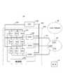
- FIG. 6is a diagram illustrating an example of the configuration of the OFC 200 in FIG.
- the OFC 200includes a flow entry creation unit 201, a route calculation unit 202, a message transmission unit 203, a packet-in identification unit 204, a broadcast packet detection unit 205, a timer 206, and a VM load information acquisition command.
- a topology information storage unit 213 for storing and managing the topology information and a user information storage unit 214 for storing user information (for example, information on the subscriber terminals 11 1 to 11 n in FIG. 1)are provided.
- Each of these units 201 to 212may realize its function by a program executed by a computer constituting the OFC 200.
- the Packet-In identifying unit 204identifies the Packet-In message sent from the OVS (220 in FIG. 5) via the secure channel. When the Packet-In identifying unit 204 detects a Packet-In message, it notifies the route calculating unit 202 and the like in order to calculate the packet transfer route of the received packet.
- the broadcast packet detection unit 205determines whether the packet received by the OVS that transmitted the Packet-In message is a PADI packet from the message identified as the Packet-In by the Packet-In identification unit 204 (PADI packet reception Existence) is determined.
- FIG. 27shows an example of the packet format of the PADI packet (see Non-Patent Document 1 for details).
- the VER field (V)is 4 bits long and 0x1 in the PPPoE version
- the TYPE field (T)is 4 bits long and 0x1 in the PPPoE version
- the CODE fieldis 8 bits long and is defined for discovery and PPP session stages.
- the SESSION_ID fieldis 16 bits long and is represented by an unsigned value
- the LENGTH fieldis 16 bits long, the length of the PPPoE payload, -TAG_TYPE is a 16-bit long field and describes TAG_TYPE and TAG_VALUE.
- TAG_LENGTHis a 16-bit long field.
- the broadcast packet detection unit 205detects that the Packet-In message notifies the reception of the PADI packet in OVS, the timer 206 starts timing and a timeout occurs. Until the notification of reception of the PADI packet from another OVS.
- the broadcast packet detection unit 205determines whether the notification of the first PADI packet reception is made based on whether the timer 206 is counting or is stopped (the operation state of the timer 205). Can do. An operation flag (not shown) (for example, 1 bit) is turned on while the timer 205 is counting, and an operation flag (not shown) is turned off while the timer 205 is stopped.
- OVSsalso receive notifications of PADI packets broadcast via the L2 network 2A from the same source (router of client 1) as the OVS that first notified the reception of PADI packets to the OFC 200 using a Packet-In message. Against. Even if the broadcast packet detection unit 205 detects the reception of the PADI packet, the broadcast packet detection unit 205 does not start the timer 206 or the like when the timer 206 is measuring time.
- the VM load information acquisition command transmission unit 207sends a VM load information acquisition command (message) for acquiring VM load information to the virtual machine (VM). Send.
- the VM load information acquisition commandis transmitted from the management plane 223 to the virtual machine (VM) 230 via the VM communication unit 212.
- the VM load information acquisition command(message) is transmitted to acquire the latest load of the virtual machine VM when a timer timeout occurs, but the present invention is limited to this configuration. Of course, it is not done.
- the VM load information acquisition command transmission unit 207transmits the VM load information acquisition command by periodic polling in advance, or uploads the load information from the VM side to the OFC side periodically.
- the load information receiving unit 208may acquire VM load information.
- the VM load information reception unit 208receives the load information transmitted from the VM 230 via the VM communication unit 212, and inputs the VM load information to the VM selection unit 209.
- the VM selection unit 209selects, for example, a virtual machine (VM) having the smallest load based on the VM load information from the VM communication unit 212, for example.
- the VM load informationmay include, for example, the number of processes per unit time (for example, authentication process), the cumulative number of processes per predetermined time, or other statistical information, etc. in the VM constituting the BAS. .
- the VM selection unit 209notifies the route calculation unit 202 of information on the selected virtual machine (VM).
- the path calculation unit 202identifies the OVS connected to the selected virtual machine (VM) from the topology information storage unit 213, and the message transmission unit 203 sends the packet-out to the OVS via the node communication unit 211.
- the messageis transferred and the transfer of the PADI packet received by the OVS is instructed (transfer destination physical port number).
- the OVS that has received the Packet-Out message from the OFC 200outputs the PADI packet from the designated port, and transfers the PADI packet to the selected VM.
- the Packet-In identifying unit 204identifies the Packet-In message transmitted from the OVS (220 in FIG. 6) and the broadcast packet detecting unit 205 does not detect the PADI packet (the packet received by the OVS is a PADI packet). If not, the OFC route calculation unit 202 calculates a route, the flow entry creation unit 201 creates a flow entry, and the message transmission unit 203 transmits a Packet-Out message.
- the broadcast packet detection unit 205 of the OFC 200receives a packet-in message for notifying the reception of a PADI packet in the OVS from the OVS for the first time, and then receives a predetermined period (that is, a timer). The time until the occurrence of timeout at 206) waits for the arrival of a Packet-In message notifying the reception of PADI from another OVS.
- a timeoutoccurs in the timer 206
- a VM load information acquisition command transmission unit 207is transmitted to a plurality of virtual machines connected to the OVS that has notified the reception of the PADI packet by the Packet-In message during the time period measured by the timer 206.
- the VM load acquisition command(Get VM load) is transmitted via the VM communication unit 212 and the management plane 223.
- a VM load information acquisition commandis also transmitted to a virtual machine (VM) connected to an OVS that does not transmit a PADI packet reception notification after the timer 206 starts timing until a timeout occurs. You may do it.
- the VM load acquisition command(Get VM load) may be multicast on the management plane 223.
- the timeout time of the timer 206may be set to a value that considers the maximum delay of broadcast packet transfer in the L2 network 2A or the like.
- Management of the timer 206causes the OFC 200 to receive a PADI packet reception notification (Packet-In message) from one OVS and then to wait for a PADI packet reception notification from another OVS indefinitely. An increase in response time is avoided. Further, the OFC 200 can accurately grasp the OVS that has received the PADI packet among the plurality of OVSs.
- PADI packet reception notificationPacket-In message
- FIG. 7shows that the PADI packet first arrives from the L2 network 2A to OVS1 in FIG. 5, and is a packet not registered in the flow entry table in OVS1, so OVS1 sends a Packet-In message to OFC200.
- the state which is presentis shown schematically.
- PADI packets from the L2 network 2Aarrive in the order of OVS2 and OVS3, and each of OVS2 and OVS3 transmits a Packet-In message to the OFC 200.
- the OFC 200receives a Packet-In message from the OVSs 2 and 3 before the time-out occurs in the timer 206 of FIG. 6, the virtual machines (VM11 to VM13, VM21 to VM23, VM31 to VM33) connected to the OVS1, OVS2, and OVS3, respectively. ), A VM load information acquisition command (Get VM Load) is transmitted.
- the OFC 200when the Packet-In message is received from the OVS 2 after the time measurement is started by the timer 206 in FIG. 6 and before the timeout occurs, the OFC 200, as described above, the virtual machine (VM11 to VM13, VMS connected to the OVS 1 and the OVS 2).
- a VM load information acquisition command(Get VM Load) may be transmitted only to the VMs 21 to 23).
- the VM selection unit 209 of the OFCbased on the VM load information received from the virtual machines (VM11 to VM13, VM21 to VM23), among the virtual machines (VM11 to VM13, VM21 to VM23) has a minimum or equivalent load. Select one of the virtual machines.
- the VM selection by the VM selection unit 209takes into account not only the load information but also the capacity (memory, storage) of hardware resources allocated to the virtual machine, the processing performance (allocated CPU), and the like. Of course, it may be determined.
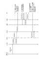
- FIG. 8is a diagram illustrating an example of an operation sequence according to the present embodiment.
- the router, L2NW, OVS1, OVS2, VM1, VM2, OFCare the client (subscriber's) router 10, L2 network 2A, OVS1, OVS2, virtual machines VM11 to VM13 (and the selected one of them) in FIG. It corresponds to the virtual machines VM21 to VM23 and OFC.
- OVS 3 in FIG. 7is omitted for convenience of drawing.
- the numbers of the respective sequencesare given. In the following description, the numbers in parentheses at the end of the sentences indicate the numbers of the sequences.
- the PADI packetis transferred to the L2NW from the router which is a PPPoE client (1).
- L2NWbroadcasts a PADI packet and arrives at OVS1 first (2).
- the header information of the received PADI packetis checked against the condition of the flow entry in the flow table held by OVS1, and since there is no match, a Packet-In message is transmitted to the OFC (3).
- the PADI packetarrives at OVS2 after the arrival of the PADI packet at OVS1 (4), and OVS2 compares the header information of the received PADI packet with the condition of the flow entry in the flow table, and there is no match. Therefore, a Packet-In message is transmitted to the OFC (5).
- the OFCreceives the Packet-In message from the OVS 1 and detects that it is receiving a broadcast packet (PADI) (6).
- the OFCstarts timing with a timer (206 in FIG. 6) and waits until a timeout occurs (7). During this wait, the OFC receives the Packet-In message transmitted from the OVS 2 with the sequence number 5.
- the OFCacquires VM load information when a timeout occurs in the timer (206 in FIG. 6) (after a certain time has elapsed) (8). That is, the OFC transmits a VM load information acquisition command (Get VM Load) to the virtual machines VM1 (VM11 to VM13) and VM2 (VM21 to VM23), respectively (9, 10).
- the virtual machine that is the destination of the VM load information acquisition command (Get VM Load)sends a PADI reception notification that triggers the start of the timer (206 in FIG. 6) by the broadcast packet detection unit (205 in FIG. 6).
- the virtual machines VM1 (VM11 to VM13) and VM2 (VM21 to VM23) connected to the OVS1 and the OVS2 that issued the PADI reception notification before the time-out in the timer (206 in FIG. 6)may be limited. .
- the virtual machine (VM) selection rangemay be narrowed down by removing virtual machines connected to the OVS that did not receive the PADI reception notification before the timer (206 in FIG. 6) timed out.
- the virtual machines VM1 (VM11 to VM13) and VM2 (VM21 to VM23)transmit their load information (VM load information) to the OFC (11, 12).
- the OFCselects a low load VM based on the VM load information from the virtual machines VM1 (VM11 to VM13) and VM2 (VM21 to VM23) (13). In this case, at least one of the virtual machines VM11 to VM13 is selected.
- the OFCinstructs the OVS 1 included in the output port connected to the selected virtual machine VM1 (at least one of the VM11 to VM13) to transfer the PADI packet received by the OVS (14). That is, the OFC transmits a Packet-Out message to the OVS 1 (15). The OVS 1 receives the Packet-Out message and transfers the held PADI packet to the VM selected by the OFC VM selection unit (209 in FIG. 6) of the virtual machines VM11 to VM13 (16).
- the OFCincludes the information of the VM selected by the OFC (the number of the OVS port (output port) connected to the selected VM) in the Packet-Out message, and in the OVS, the VM 11 to the VM 13
- the PADI packetmay be transferred to the VM from the selected output port (selected port) connected to the VM.
- the OFCinstructs the OVS 1 to output from the port corresponding to the VM 12 using the Packet-Out message.
- the OFCcan directly transfer the PADI packet to the selected VM without using the Packet-Out message.
- the OFCcan also set an entry that defines processing for rewriting the destination MAC address of the PADI packet with the destination MAC address of the selected VM in the OVS. For example, when the VM 12 is selected as a transfer destination by the OFC, an entry that defines a process for rewriting the destination MAC address (broadcast address) of the PADI packet with the destination MAC address of the VM 12 is set in the OVS 1.
- an entry that defines a process for rewriting the destination MAC address (broadcast address) of the PADI packet with the destination MAC address of the VM 12is set in the OVS 1.
- the VM that has determined the PADI packet without transmitting the Packet-In again to the OFC 200Therefore, the communication load on the OFC 200 can be suppressed. Further, in this case, when the function of the VM corresponding to the BRAS is terminated, for example, the OFC 200 deletes the entry set in the corresponding OVS.
- the sequence after the PADI packet is transmitted to the VMfollows the sequence of FIG. 2 described above (however, the OVS that has received the new packet transmits the Packet-In message to the OFC). In response to the Packet-Out message from the OFC, the packet is transferred from the designated output port).
- the PADO packet (see FIG. 2) of the unicast packet that is a response from the virtual machine VM that has received the PADI packet to the routeris transferred from the virtual machine VM to the OVS to which the virtual machine VM is connected in the data plane.
- a Packet-In messageis transmitted to the OFC.
- the packet transfer path (packet transfer path on the OpenFlow network) of the PADO packetis calculated, and a Packet-Out message is transmitted to the OVS to instruct packet transfer from the designated physical port.
- the OVStransfers the PADO packet transferred from the virtual machine VM to the L2 network, and is transferred from the L2 network 2A to the router 10 (see FIG.
- a unicast PADR packet from the router 10(see FIG. 5) is transferred from the L2 network 2A to the OVS.
- the OVS that has received the PADR packettransmits a Packet-In message to the OFC.
- the OFCtransmits a Packet-Out message to the OVS, and the OVS transmits the PADR packet to the virtual machine VM that is the transmission source of the PADO packet.
- the virtual machine VM that has received the PADR packetissues a session ID and transmits a PADS packet including the session ID to the OVS to which the VM is connected.
- a Packet-In messageis transmitted to the OFC.
- the packet transfer path of the PADS packetis calculated, and a packet-out message is transmitted to the OVS to instruct packet transfer from the designated physical port.
- the OVStransfers the PADS packet to the L2 network 2A (see FIG. 5) and is transferred to the router 10.
- FIG. 9is a diagram showing a configuration of a modified example of the OFC of FIG.
- the OFC 200 ′ shown in FIG. 9is different in that the timer 206 of FIG. 6 is deleted.
- the other configuration of the OFC 200 ′ illustrated in FIG. 9is the same as that of the OFC 200 illustrated in FIG.
- differences from FIG. 6will be described.
- the OFC 200 ′when the OFC 200 ′ receives a Packet-In message for notifying a new reception of a PADI packet from the OVS, and the broadcast packet detection unit 205 detects reception of the PADI packet, the VM load information acquisition command transmission unit 207 A VM load information acquisition command Get VM Load is transmitted from the management plane 223 to the VM (virtual machine).
- FIG. 10is a diagram for explaining the sequence operation of the modified example of FIG. Hereinafter, differences from FIG. 8 will be described.
- VM load information acquisition commandGet VM Load
- VM1VM11 to VM13
- VM2VM21 to VM23
- the PADI packetafter the arrival of the PADI packet to OVS1, the PADI packet also arrives at OVS2 (4).
- the header information of the received PADI packetis checked against the condition of the flow entry in the flow table and matches. Therefore, the OFC notifies the OFC of the reception of the new packet by the Packet-In message (5), but the OFC does not perform the process related to the reception of the PADI packet notified by the Packet-In message from the OVS2.
- VM1(VM11 to VM13) and VM2 (VM21 to VM23) transmit their load information (VM load information) to the OFC (10, 11).
- the OFCselects a low load VM based on the VM load information (12). In this case, the OFC selects at least one of the VM21 to VM23.
- the OFCinstructs the OVS 2 having the output port connected to the selected VM to transfer the PADI packet (13). That is, the OFC transmits a Packet-Out message to the OVS 2 (14).
- the OVS 2receives the Packet-Out message and is selected by outputting the held received PADI packet from the output port connected to the VM selected by the VM selection unit 209 of the OFC among the VMs 21 to 23. (15).
- the switchis not limited to the virtual switch OVS, and can be applied to an OFS that is a real device (normal device) as will be described later.
- the BRAS function(or BAS function) is not limited to being applied to a virtual machine (VM), but a plurality of processing units in which the BRAS function is distributed to a plurality of physical machines (Processor Elements).
- VMvirtual machine
- Processor Elementsphysical machines
- FIG. 11is a diagram for explaining the second embodiment.
- an OpenFlow function(OFS) is mounted on a DSLAM 21 ′ that multiplexes a plurality of ADSL lines.
- the OFC 27uses, for example, an OFS (not shown) in the DSLAM 21 ′, a VLAN tag and a port VLAN corresponding to the virtual machine (VM) on which the BRAS to which the PADI packet is transferred operates in the header of the PADI packet. Set and transfer to BRAS.
- SET_VLAN_VIDprocessing to add / update Vlan Tag with a specified VLAN ID
- SET_VLAN_VIDis set from the OFC as an action that matches the conditions of the PADI packet in the OFS flow table in the DSLAM 21 ′, and in the OFS, the VLAN ID is set in the PADI packet and transferred. It may be.
- the number of virtual machines (VM1) 230 1 , 230 2 , and 230 3is not limited to one, and a plurality of virtual machines may be connected in parallel as shown in FIG.
- FIG. 12Ais a diagram illustrating an example of the configuration of the DSLAM 21 ′ in FIG.
- an ATM (Asynchronous Transfer Mode) switch 21-1switches (switches) ATM cells from a plurality of ADSL lines 15 1 to 15 n (n is an integer of 2 or more).
- the ATM-ether conversion unit 21-2performs protocol conversion between the ATM cell and the Ethernet (registered trademark) frame.
- an OpenFlow functionwhen the OFS 21-4 receives a packet converted into an Ether frame by the ATM-Ether conversion unit 21-2, if a flow entry corresponding to the packet is not registered in the flow entry, the Packet-In message Is transmitted to the OFC 27.
- the OFC 27determines the packet transfer destination, transmits a Packet-Out message to the OFS 21-4, and instructs the OFS 21-4 to transfer the PADI packet from the designated port.
- a configuration including a plurality of OFSsmay be used.
- the DSLAM 21 ′may be mounted on the virtual machine.
- the OFC 21-4may be configured as a virtual switch (OVS).
- FIG. 12Bis a diagram showing a configuration of the DSLAM 21 of the related technology such as FIG.
- the DSLAM 21includes an ATM switch 21-1, an ATM-Ether conversion unit 21-2, and an interface unit 21-3.
- the interface unit 21-3is a transmission / reception interface connected to Ethernet (registered trademark) such as 10BASE-T or 100BASE-TX.
- the carrier networkis divided into several VLANs (for example, three VLANs in FIG. 11), and in the DSLAM 21 ′, the broadcast packet (PADI) transfer destination VLAN is set as the broadcast packet header (frame header). ) To the BRAS / BAS load distribution.
- PADIbroadcast packet
- FIG. 13is a diagram for explaining the third embodiment.
- a load balancer (LB) 28that performs load balancing of a network and virtual machines is provided.
- the OpenFlow functionis mounted on the DSLAM 21 ′′ as in the second embodiment.
- the OFS (not shown) mounted on the DSLAM 21 ′′may be mounted as a virtual switch OVS.
- the load balancer (LB) 28uses a round robin method that sequentially assigns a plurality of virtual machines, a dynamic allocation method that is determined based on a monitoring result of the load on the virtual machine, and the like.
- a destination virtual machine (VM)is determined.
- the load balancer (LB) 28may be mounted on a virtual machine on the server.
- the OFS (not shown) of the DSLAM 21 ′′transmits a Packet-In message to the OFC 27, and the OFC 27 sends the OFS (not shown) of the DSLAM 21 ′′.
- the PADI packetis instructed to be transferred to the load balancer (LB) 28.
- the PADI packetis transferred from the port connected to the load balancer (LB).
- a flow entry that defines a rulemay be added, and the load balancer (LB) 28 transfers the PADI packet transferred from the OFS to the selected virtual machine.
- FIG. 14is a diagram showing a configuration example of the DSLAM 21 ′′ in FIG. 13.
- the OFS 21-4 of the DSLAM 21 ′′is added to the load balancer (LB) 28 with respect to the DSLAM 21 ′ in FIG. Has a port to connect.
- the OFS 21-4 of the DSLAM 21 ′′transmits a Packet-In message to the OFC 27.
- the OFC 27instructs the OFS 21-4 to transfer the PADI packet to the load balancer (LB) 28.
- the load balancer (LB) 28transfers the PADI packet transferred from the OFS 21-4 to the selected virtual machine 230.
- the OFC 27will receive the packet. -Transfer the Out message to the OFS 21-4 and instruct the OFS 21-4 to transfer the received packet directly to the destination virtual machine (VM) without transferring it to the load balancer (LB) 28.
- VMvirtual machine
- LBload balancer
- the load balancer (LB) 28acquires the flow entry statistical information for each flow from the OFS 21-4, and selects the virtual machine (VM) of the flow with the least load based on the load of the flow.
- the transfer destination of the PADI packetmay be determined.
- the PADI packet received by the OpenFlow switchis transferred to a dedicated load balancer (LB), and the transfer destination of the PADI packet in consideration of load distribution is determined by the load balancer (LB). Since the load balancer (LB) is separately provided, the effect of load distribution can be enhanced. Also, the concentration of load on the OFC can be avoided.
- FIG. 15is a diagram for explaining the fourth embodiment.
- the DSLAM 21 ′ ′′has a load balance function (LB) 28 ′.
- LBload balance function
- the DSLAM 21 ′ ′′selects a PADI packet transfer destination virtual machine (VM) based on the control of the load balance function (LB) 28 ′, and selects the selected virtual machine (VM). ) To the PADI packet.
- the DSLAM 21 ′ ′′When the DSLAM 21 ′ ′′ receives a packet other than the PADI packet from the ADSL line (15 1 to 15 n ), for example, the destination specified by the header of the packet is not controlled by the load balance function (LB) 28 ′.
- the virtual machine (VM)may be transferred.
- FIG. 16is a diagram illustrating the configuration of the DSLAM 21 ′ ′′ according to the fourth embodiment.
- the DSLAM 21 shown in FIG. 12Bincludes a load balancer (LB) 28 '.
- the load balancer (LB) 28 ′controls the interface circuit (IF) 21-3 to transmit a PADI packet to the selected virtual machine.
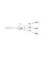
- FIG. 17is a diagram for explaining the fifth embodiment.
- a load balancer (LB) 28is provided in the subsequent stage of the DSLAM 21.
- the PADI packet output from the DSLAM 21is transferred to the virtual machine (VM) selected by the load balancer (LB) 28.
- the load balancer (LB) 28uses a round robin method for allocating a plurality of virtual machines (VMs) 230 1 to 230 3 in order, a dynamic allocation method for determining based on the monitoring results of loads on the virtual machines 230 1 to 230 3 , etc.
- the virtual machines (VMs) 230 1 to 230 3 to which the PADI packet is transferredare determined by the above.
- the load balancer (LB) 28may be mounted on a virtual machine on the server.
- the transfer destination of the broadcast packetcan be determined in consideration of load distribution. If the load balancer is configured by a dedicated device without being virtualized, the processing speed can be increased.
- FIG. 18is a diagram illustrating a configuration of the sixth embodiment.
- OFS1, OFS2, and OFS3are arranged at the boundary between the L2 network 31 and the OpenFlow network 32.
- HOST 1, 2, and 3such as servers are connected to end nodes OFS 7 and 8 of the OpenFlow network 32.
- OFS 1 to OFS 8 of the OpenFlow network 32are centrally managed by the OFC 300.
- FIG. 19is a diagram schematically showing a state where the broadcast packet BP from the L2 network 31 is transferred to the OpenFlow network 32.
- the OFS 1receives the broadcast packet BP, and since a corresponding flow entry is not found, transmits a Packet-In message to the OFC 300 and requests flow setting (path calculation) for the broadcast packet BP.
- the broadcast packet BPis received, and since a corresponding flow entry is not found, a Packet-In message is transmitted to the OFC 300 and a route calculation is requested.
- the OFSis selected (for example, OFS1), the flow (route) for transferring the broadcast packet BP is calculated, the flow entry is set in the OFS on the route (the FlowModify message is set to OFS4, OFS7). And a Packet-Out message is transmitted to the selected OFS1. Packet-Out messages are not transmitted to unselected OFS2 and OFS3.
- the OFS 1 that has received the Packet-Out messagetransfers the broadcast packet BP from the designated output port to the OFS 4. Further, the broadcast packet BP is transferred from OFS 4 to OFS 7, 8 to HOST 1, 2, 3.
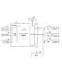
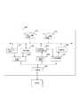
- FIG. 20is a diagram illustrating the configuration of the OFC 300 according to the sixth embodiment.
- the OFC 300includes a flow entry creation unit 301, a route calculation unit 302, a message transmission unit 303, a Packet-In identification unit 304, a broadcast packet (Broadcast packet) detection unit 305, a timer 306, and an OFS load monitoring unit 307.
- the broadcast packet detection unit 305When the broadcast packet detection unit 305 first detects a broadcast reception notification, the timer 306 is started, and when a timeout occurs in the timer 306, the OFS load monitoring unit 307 notifies the OFS 1, 2, and 3 of the OFS load information.
- the OFS loadmay be monitored by transmitting an acquisition command and acquiring flow entry statistical information (such as the number of received bytes) from the OFS.
- the OFS load monitoring unit 307may send an OFS load information acquisition command to the OFSs 1 to 8 constituting the OpenFlow network 32 to derive a load for each flow.
- the OFS load monitoring unit 307obtains load information such as traffic by including the flow entry statistical information (the number of received packets, the number of received bytes, etc.) from the OFS in the Packet-In message from the OFS. You may make it do.
- the OFS load monitoring unit 307periodically acquires and records OFS load information by polling or the like, and immediately inputs the OFS load information to the OFS selection unit 308 when a timeout occurs in the timer 306. You may make it do.
- the OFS selection unit 308selects the OFS with the smallest load from the OFS that transmitted the Packet-In message, and the message transmission unit 303 transmits the Packet-Out message to the OFS selected by the OFS selection unit 308. .
- the route calculation unit 302calculates the route from the selected OFS to the broadcast packet transfer destination HOSTs 1, 2, and 3, and the flow entry creation unit 301 creates a flow entry for the OFS on the broadcast packet transfer route.
- a flow entry setting command (Flow-Modify)is transmitted to the OFS on the broadcast packet transfer path via the message transmission unit 303. Note that the OFS on the broadcast packet transfer path receives the flow entry setting command (Flow-Modify) and adds the flow entry to the flow table.
- FIG. 21is a diagram for explaining the sequence operation of the sixth embodiment.
- L2NW, OFS1, OFS2 / 3, OFS4-8, HOST1-3, and OFCcorrespond to the L2 network 31, OFS1, OFS2 / 3, OFS4-8, HOST1-3, and OFC300 in FIG.
- the numbers of the respective sequencesare given.
- the numbers in parentheses at the end of the sentencesindicate the numbers of the sequences.
- the OFS load information acquisition command transmission sequenceis shown in the OFS load monitoring unit 307 in consideration of the case where the OFS load information has already been acquired when a timeout occurs in the timer 306. Absent.
- Broadcast packetarrives at L2 network (1).
- Broadcast packet from L2 networkarrives at OFS1 (2).
- OFS1sends a Pcake-In message to the OFC (3).
- Broadcast packet from L2 networkarrives at OFS2 (4).
- OFS1receives the Pcake-In message, and when it detects that the broadcast packet is received by OFS1, starts the timer (306 in FIG. 20) (6).
- the OFCselects OFS1 from the OFS load monitoring result (8), sends a Packet-Out message to OFS1, and transmits a broadcast packet from the designated port.
- the transferis instructed (10).
- the OFCtransmits a Flow-Modify message to OFS 4, 7, and 8 on the transfer path of the broadcast packet, and OFS 4, 7, and 8 each flow based on the Flow-Modify message.
- An entryis set in the flow table (9). For example, in the flow table of OFS 7, when the PADI packet is received, a flow entry of processing (Actions) for outputting the PADI packet from three output ports respectively connected to HOST1, HOST2, and OFS8 is set.
- OFS1transfers the broadcast packet from the designated port to OFS4 (11), and the broadcast packet is transferred to HOST1, 2, 3 via OFS7, 8 (12).
- the packet headermatches the matching field (MatchMField) of the flow entry set from the OFC.
- the broadcast packetis transferred from the designated port according to the flow entry processing field (Actions) (see FIG. 28) without transmitting a Packet-In message to the server.
- Actionsflow entry processing field
- Packet-Out messagesare not transmitted to OFS 2 and OFS 3 other than OFS 1, and broadcast packets are not transferred from OFS 2 and OFS 3.
- the OFS selection unit 308 of the OFC 300indicates that the OFS 1 selected from the OFS notified of the reception of the broadcast packet by the Packet-In message is in a transferable state (Forwarding) excluding the port where the broadcast packet has arrived. It may be transferred to all ports in the (status). Further, the subsequent OFSs 4, 7, 8, etc. may be transferred to all ports in the transferable state (Forwarding state) excluding the port where the broadcast packet from the previous OFS has arrived.
- each of the OFSs 1, 2, and 3transfers broadcast packets.
- the traffic of broadcast packets transferred on the OpenFlow networkcan be greatly reduced.
- FIG. 22is a diagram illustrating a configuration of an OFC according to a modification of the sixth embodiment.
- the timer 306 of FIG. 20is deleted in the OFC of this modification.
- Other configurationsare the same as those in FIG.
- the OFC 300starts the timer 306 when the reception of the broadcast packet is first notified from the OFS, notifies the OFS load monitoring unit 307 when a timeout occurs, and selects the OFS by the OFS selection unit 308. Yes.
- the OFSwhen the reception of the broadcast packet is first notified from the OFS at the boundary, the OFS can be performed without waiting for the reception of the broadcast packet from another OFS at the boundary.
- the load monitoring unit 307is notified, and the OFS selection unit 308 selects the OFS.
- the OFSwhen the reception of the broadcast packet is notified from any of OFS 1 to 3 at the boundary between the L2 network 31 and the OpenFlow network 32, the lowest load OFS may be selected.
- the OFSwhen the reception of the broadcast packet is first notified from the OFS at the boundary, the OFS may be selected. In this case, the OFS load monitoring unit 307 is unnecessary.
- FIG. 23is a diagram for explaining the operation of the modified example described with reference to FIG. Hereinafter, differences from FIG. 21 will be described.
- OFCwhen receiving the Pcake-In message from OFS1, without waiting for the Pcake-In message (5) from OFS2, OFS1 is selected from the load monitoring result of OFS (6), and the Packet-Out message is transmitted to OFS1. (8). Further, the OFS transmits a Flow-Modify message to the OFSs 4 and 7 to set the transfer path of the broadcast packet (7). OFS1 forwards the broadcast packet to OFS4 (9), and forwards to HOST1, 2, 3 via OFS7, 8 (10). Of the OFS 1 to 3 at the boundary, Packet-Out messages are not transmitted to OFS 2 and OFS 3 other than OFS 1.
- each of OFS 1, 2, and 3is broadcasted by selecting at least one of OFS 1, 2, and 3 at the boundary between the L2 network 31 and the OpenFlow network 32, as in the sixth embodiment.
- the traffic of the broadcast packet transferred on the OpenFlow networkcan be greatly reduced.
- management by the timer of the second embodimentis unnecessary.
- FIG. 24is a diagram for explaining Embodiment 7 of the present invention.
- the second network 42 of the seventh embodimentis obtained by replacing OFS 1 to 8 of the OpenFlow network of the second embodiment with switches SW 1 to SW 8 such as L2 switches.
- the switches SW1 to SW8duplicate the broadcast packet (BP) and output it from a plurality of ports (for example, flooding to all output ports).
- the controller 400selects one of the switches SW1, SW2, and SW3, and the rest Is not selected.
- the selected switchfloods the received broadcast packet, for example.
- the non-selected switchdoes not transfer the received broadcast packet. Thereby, the occurrence of broadcast overflow in the network 42 can be suppressed.
- the controller (CTRL) 400that has received the notification of broadcast packet reception from SW1 selects SW1.
- the controller 400also receives broadcast packet reception notifications from the switches SW2 and SW3, but the switches SW2 and SW3 are not selected, and the broadcast packets are not transferred from the switches SW2 and SW3.
- the controller (CTRL) 400 that has received the broadcast packet reception notification from the switch SW1may select a specific output port (at least one output port) of the switch SW1.
- Both the first network 41 and the second network 42may be configured by an L2 network.
- the switches SW1 to S8are, for example, L2 switches, like the switch SW of the first network 41.
- FIG. 25is a diagram illustrating the configuration of the controller 400 according to the seventh embodiment.
- the controller 400includes a port / switch (PORT / SW) selection unit 401, a packet reception detection unit 402, and a switch information storage unit 403.
- the packet reception detection unit 402detects reception of the broadcast packet by receiving a notification from the switch SW.
- the port / switch selection unit 401In response to detection of broadcast packet reception at the switch SW in the packet reception detection unit 402, the port / switch selection unit 401 refers to the switch information storage unit 403, and switches SW1 to SW1 according to the transfer destination of the broadcast packet. At least one switch is selected from SW3, and the remaining switches are not selected. Alternatively, the port / switch selection unit 401 refers to the switch information storage unit 403 and selects a port of at least one switch from the switches SW1 to SW3. At least one selected switch forwards broadcast packets, eg, from all ports, and the remaining switches do not forward broadcast packets. Alternatively, at least one switch for which at least one output port is selected forwards a broadcast packet from the selected at least one output port.
- FIG. 26is a diagram for explaining the operation of the seventh embodiment.
- NW, SW1, SW2 / 3, SW4-8, HOST1-3, and CTRLcorrespond to network 41, switch SW1, SW2 / 3, SW4-8, host HOST1-3, and controller CTRL400 in FIG. 24, respectively. is doing.
- the numbers of the respective sequencesare given. In the following description, the numbers in parentheses at the end of the sentences indicate the numbers of the sequences.
- Broadcast packetarrives at network (NW) (1).
- Broadcast packet from NWarrives at switch SW1 (2).
- the controllerWhen receiving a broadcast packet reception notification from the switch SW1, for example, the controller (CTRL) selects the switch SW1 (or port) (6).
- the controller (CTRL)transmits a broadcast packet transfer instruction to the switch SW1 (7).
- SW1transfers the broadcast packet to the switch SW4 (8), and is transferred to the HOSTs 1, 2, and 3 via the switches SW7 and SW8 (9).
- the switchBy selecting at least one of the switches SW1, 2, and 3 at the boundary between the first network 41 and the second network 42 (or at least one output port among the plurality of output ports of the switch SW), the switch Compared to the case where all of SW1, 2, 3 transfer broadcast packets from all output ports, the traffic of broadcast packets transferred over the network is greatly reduced, and the network (broadcast domain) overflows with broadcast packets. It is possible to avoid that.
- the port / switch selection unit 401may select a low-load switch based on the loads of the switches SW1 to SW3.
- the controller 400 in FIG. 25starts a timer (not shown) and selects a switch when a timeout occurs in the timer. May be.
- multicast packets that use IP multicast group addressessuch as network switches and routers that copy packets and forward them to multiple recipients
- transfer route information for the packetsswitch connection information, etc.
- at least one of the switches SW1 to SW3may be selected.
Landscapes
- Engineering & Computer Science (AREA)
- Computer Networks & Wireless Communication (AREA)
- Signal Processing (AREA)
- Software Systems (AREA)
- Theoretical Computer Science (AREA)
- Physics & Mathematics (AREA)
- General Engineering & Computer Science (AREA)
- General Physics & Mathematics (AREA)
- Computer Security & Cryptography (AREA)
- Data Exchanges In Wide-Area Networks (AREA)
Abstract
Description
Translated fromJapanese (関連出願についての記載)
本発明は、日本国特許出願:特願2013-133050号(2013年6月25日出願)の優先権主張に基づくものであり、同出願の全記載内容は引用をもって本書に組み込み記載されているものとする。
本発明は通信システムと装置と方法とプログラムに関する。(Description of related applications)
The present invention is based on the priority claim of Japanese patent application: Japanese Patent Application No. 2013-133050 (filed on June 25, 2013), the entire contents of which are incorporated herein by reference. Shall.
The present invention relates to a communication system, an apparatus, a method, and a program.
ネットワークをソフトウェアで制御できるようにするSDN(Software Defined Network)技術や、例えばコア網(Core Network)等のネットワーク機能を仮想化する「NFV(Network Functions Virtualization)」等、ネットワークにおいても、IT(Intelligent Technology)技術で培われたサーバ仮想化等によるネットワークアプライアンス(機器)の仮想化に関心が高まっている。例えば欧州の標準化団体「ETSI」(European Telecommunications Standards Institute)のNFVグループには多くの有力通信事業者、ベンダ等が参加している。通信事業者の網に含まれる様々なアプライアンス、例えばモバイルコアの機能であるMME(Mobility Management Entity)、S-GW(Serving-GateWay)、P-GW(Packet Data Network-GateWay)、ルータ、大規模NAT(LSN:Large Scale Network address translation)、HLR(Home Location Register)、RNC(Radio Netwok Controller)/eNodeB、ファイアウォールや認証サーバ等は、現在、それぞれ専用機器で構成されている。IT (Intelligent) is also used in networks such as SDN (Software Defined Network) technology that makes it possible to control the network with software and “NFV (Network Functions Virtualization)” that virtualizes network functions such as the Core Network. Technology) Network appliances (equipment) by server virtualization, etc. cultivated by technology are becoming more and more interested. For example, many leading telecommunications carriers and vendors participate in the NFV group of the European standardization organization “ETSI” (European Telecommunications Standards Institute). Various appliances included in the network of telecommunications carriers, such as MME (Mobility Management Entity), S-GW (Serving-Gateway), P-GW (Packet Data Network-Gateway), router, large scale NAT (LSN: Large Scale Network address translation), HLR (Home Location Register), RNC (Radio Netwok Controller) / eNodeB, firewall, authentication server, and the like are each configured with dedicated devices.
NFVでは、これら専用装置に実装されていたネットワーク機器等を、例えば汎用のサーバを用いたサーバ仮想化技術で実装することで、設備コスト、運用コストの削減を図る。また、制御信号等の通信負荷の増大等に対してリソースを追加することで、耐障害性を高めることを可能としている。NFV aims to reduce equipment costs and operational costs by implementing network devices, etc., mounted on these dedicated devices, for example, with server virtualization technology using a general-purpose server. Moreover, it is possible to improve fault tolerance by adding resources to an increase in communication load such as a control signal.
図1は、事業者網(キャリアネットワーク)を模式的に例示した図である。この事業者網は、後述する実施形態の適用対象とされるネットワークの一例でもあるので、その関連技術を説明しておく。FIG. 1 is a diagram schematically illustrating a carrier network (carrier network). Since this provider network is also an example of a network to which an embodiment described later is applied, its related technology will be described.
図1には、PPPoE(Point to Point Protocol over Ethernet(登録商標))による接続の一例が模式的に示されている。PPPoEについては、例えば非特許文献1が参照される。加入者宅内1の端末111~11nはルータ10、ADSL(Asymmetric Digital Subscriber Line)モデム12、ADSL回線15を介して、局舎のDSLAM(Digital Subscriber Line Access Multiplexer)21に接続される。BAS(Broadband Access Server)20は、ルータの機能を持つアクセスサーバであり、ユーザからの接続認証やプロバイダ識別子に従いプロバイダ30の切り替えや帯域管理を行う。DSLAM21は複数のADSL回線を1つに束ねるレイヤ2(L2)の集線装置である。なお、BASはBRAS(Broadband Remote Access Server)であってもよい。以下では、ADSLで説明するが、ADSLのかわりに、FTTH(Fiber To The Home)であってもよい(この場合、モデムは不要であり、ルータはFTTH用ルータとなる)。FIG. 1 schematically shows an example of connection by PPPoE (Point to Point Protocol over Ethernet (registered trademark)). Regarding PPPoE, for example, Non-Patent
PPPoE接続では加入者宅内のルータ10(クライアント)と、アクセスサーバBAS20との間をブリッジ接続しPPP(Point to Point Protocol)接続を行う。BAS20は、例えば、「ユーザID@プロバイダ識別子」のユーザアカウントにより、どのプロバイダ(ISP:Internet Service Provider)に接続するか認識しユーザの認証を行い、プロバイダとの接続点へユーザデータを転送する。ルータ10からDSLAM21まではPPPoEによるトンネリングが行われ、DSLAM21とBAS20間はL2TP(Layer 2 Tunneling Protocol)によるトンネリングが行われる。In PPPoE connection, the router 10 (client) in the subscriber premises and the
図2は、PPPoEディスカバリステージのシーケンス動作を説明する図である。PPPoEセッションの開始は、PPPoEクライアントであるルータ側からのPADI(PPPoE Active Discovery Initiation)パケットの送信で開始する。PADIパケットは、図27にヘッダーフォーマットを例示したように、ヘッダの宛先MACアドレス(48ビット)が全て1のブロードキャストパケットである。FIG. 2 is a diagram for explaining the sequence operation of the PPPoE discovery stage. The PPPoE session is started by transmitting a PADI (PPPoE Active Discovery Initiation) packet from the router side which is a PPPoE client. The PADI packet is a broadcast packet whose destination MAC address (48 bits) is all 1 as exemplified in the header format in FIG.
BASは、サービス可能なPADIを受けると、応答パケットPADO(PPPoE Active Discovery Offer)を、PADIを送信したホストであるルータ(図1の10)に返す。When the BAS receives a serviceable PADI, the BAS returns a response packet PADO (PPPoE Active Discovery Offer) to the router (10 in Fig. 1) that is the host that sent the PADI.
ルータは、受信したPADOの送信元のBAS宛に、ユニキャストでPADR(PPPoE Active Discovery Request)を送信したのち、PADRを送信したBASとの間でセッションを開始する。なお、ルータがPADRを送信後、セッションを開始するまでの手順の説明は省略する。The router transmits a PADR (PPPoE Active Discovery Request) by unicast to the BAS that is the source of the received PADO, and then starts a session with the BAS that sent the PADR. A description of the procedure from when the router transmits the PADR until the session is started will be omitted.
以下に関連技術の分析を与える。The following is an analysis of related technologies.
上記した通り、NFV等では、通信事業者のネットワークアプライアンスを、汎用サーバの仮想化基盤上の仮想マシン上に実装することにより、ネットワークアプライアンスの仮想化を実現している。As described above, in NFV and the like, network appliance virtualization is realized by mounting a network appliance of a communication carrier on a virtual machine on a virtualization platform of a general-purpose server.
図3は、例えばBRAS/BASを仮想化した構成(プロトタイプ)を例示する図である。図3に示すように、BRAS機能(BRAS1、2、3)は、サーバの仮想化基盤上の仮想マシン(VM)2301、2302、2303上でそれぞれ動作するソフトウェアによって実現される。FIG. 3 is a diagram illustrating a configuration (prototype) obtained by virtualizing BRAS / BAS, for example. As shown in FIG. 3, the BRAS function (BRAS1 ,2 ,3 ) is realized by software operating on virtual machines (VMs) 2301 , 2302 , 2303 on the virtualization infrastructure of the server.
図3に示したように、BRAS/BASを仮想化した場合では、BRAS/BASの機能のみを実行する専用装置のかわりに、汎用装置(汎用サーバ上の仮想マシン)を使うため、専用装置を用いる場合と比較して、BRAS/BASの処理性能が低くなる。As shown in FIG. 3, when BRAS / BAS is virtualized, a general-purpose device (virtual machine on a general-purpose server) is used instead of a dedicated device that executes only the BRAS / BAS function. Compared with the case of using, the processing performance of BRAS / BAS is lowered.
このため、BRAS/BASを仮想化した場合には、BRAS/BASの処理性能を考慮して、個々のBRAS/BASが収容するセッション数(クライアント数)の負荷分散を行う必要がある。For this reason, when BRAS / BAS is virtualized, it is necessary to distribute the load of the number of sessions (number of clients) accommodated by each BRAS / BAS in consideration of the processing performance of BRAS / BAS.
一方、現在のPPPoEのプロトコルでは、図2を参照して説明したように、PADIというブロードキャストパケットによりセッションを確立している。すなわち、クライアントがPADIを送り、複数のBRAS/BASが応答した場合、クライアントがどれか1つを選択してセッションを確立することになっている。On the other hand, in the current PPPoE protocol, as described with reference to FIG. 2, a session is established by a broadcast packet called PADI. That is, when a client sends PADI and a plurality of BRAS / BAS responds, the client selects one of them and establishes a session.
つまり、現在のPPPoEプロトコルでは、複数のBRAS/BASからの応答に対して、どのBRAS/BASとのセッションを確立するか、を選択することができない。このため、上記のような現状のPPPoEプロトコルでは、BRAS/BASの負荷分散を行うことは難しい。In other words, in the current PPPoE protocol, it is not possible to select which BRAS / BAS to establish a session for responses from a plurality of BRAS / BAS. For this reason, with the current PPPoE protocol as described above, it is difficult to perform BRAS / BAS load balancing.
したがって、本発明は、上記問題点に鑑みて創案されたものであって、その目的は、ネットワークシステム全体での負荷分散を可能とするシステム、装置、方法、プログラムを提供することにある。Therefore, the present invention has been made in view of the above problems, and an object of the present invention is to provide a system, apparatus, method, and program that enable load distribution over the entire network system.
本発明のいくつかの側面の1つによれば(視点1)、通信ネットワークで用いられるハードウェア機器の通信機能を仮想マシンが実行する通信システムにおける通信制御装置であって、前記通信機能と通信セッションを確立するために複数の経路に向けて転送されるパケットの転送先を、複数の前記仮想マシンから選択する第一の手段と、前記パケットを、選択された仮想マシンに転送する第二の手段とを有する通信制御装置が提供される。According to one of several aspects of the present invention (viewpoint 1), a communication control apparatus in a communication system in which a virtual machine executes a communication function of a hardware device used in a communication network, the communication function and the communication function. A first means for selecting, from a plurality of the virtual machines, transfer destinations of packets to be transferred toward a plurality of paths to establish a session; and a second means for transferring the packets to the selected virtual machines A communication control device is provided.
他の側面によれば(視点2)、通信ネットワークで用いられるハードウェア機器の通信機能を仮想マシンが実行する通信システムにおける通信制御方法であって、前記通信機能と通信セッションを確立するために複数の経路に向けて転送されるパケットの転送先を、複数の前記仮想マシンから選択し、前記パケットを、選択された仮想マシンに転送する、通信制御方法が提供される。According to another aspect (viewpoint 2), there is a communication control method in a communication system in which a virtual machine executes a communication function of a hardware device used in a communication network, and a plurality of methods are used to establish a communication session with the communication function. There is provided a communication control method for selecting a transfer destination of a packet to be transferred toward the path from a plurality of the virtual machines and transferring the packets to the selected virtual machine.
さらに他の側面によれば(視点3)、通信ネットワークで用いられるハードウェア機器の通信機能を仮想マシンが実行する通信システムにおける通信制御装置に、前記通信機能と通信セッションを確立するために複数の経路に向けて転送されるパケットの転送先を、複数の前記仮想マシンから選択する処理と、前記パケットを、選択された仮想マシンに転送する処理と、を実行させる通信制御プログラムが提供される。According to still another aspect (viewpoint 3), a communication control device in a communication system in which a virtual machine executes a communication function of a hardware device used in a communication network, a plurality of communication functions and a communication session are established in order to establish a communication session. There is provided a communication control program for executing a process of selecting a transfer destination of a packet transferred toward a path from a plurality of the virtual machines and a process of transferring the packets to the selected virtual machine.
さらに他の側面によれば(視点4)、上記視点3のプログラムを記録したコンピュータ読み出し可能な媒体(半導体メモリ、磁気/光ディスク等)が提供される。According to still another aspect (viewpoint 4), a computer-readable medium (semiconductor memory, magnetic / optical disk, etc.) on which the program of
さらに他の側面によれば、通信ネットワークで用いられるハードウェア機器の通信機能を仮想マシンが実行する通信システムの通信制御装置であって、前記通信機能と通信セッションを確立するために複数の経路に向けて転送されるパケットの転送先を、複数の前記仮想マシンから選択する第一の手段と、前記パケットを選択された仮想マシンに転送することを、ネットワークスイッチに指示する第二の手段とを有する通信制御装置が提供される。According to still another aspect, a communication control device of a communication system in which a virtual machine executes a communication function of a hardware device used in a communication network, and a plurality of paths are established to establish a communication session with the communication function. A first means for selecting a transfer destination of a packet forwarded from a plurality of the virtual machines, and a second means for instructing a network switch to transfer the packet to the selected virtual machine. A communication control device is provided.
さらに他の側面によれば、通信ネットワークで用いられるハードウェア機器の通信機能を仮想マシンが実行する通信システムにおける通信装置であって、前記通信機能と通信セッションを確立するために複数の経路に向けて転送されるパケットを識別する手段と、複数の前記仮想マシンから選択された仮想マシンに前記パケットを転送する装置に、識別した前記パケットを集約する手段とを有する通信装置が提供される。According to still another aspect, a communication device in a communication system in which a virtual machine executes a communication function of a hardware device used in a communication network, and is directed to a plurality of paths in order to establish a communication session with the communication function There is provided a communication apparatus comprising: means for identifying the packets transferred in the above; and means for aggregating the identified packets in an apparatus for forwarding the packets to a virtual machine selected from a plurality of the virtual machines.
さらに他の側面によれば、通信ネットワークで用いられるハードウェア機器の通信機能を実行する仮想マシンが配置される情報処理装置であって、ネットワークスイッチの機能を有する仮想スイッチを稼動させるための手段を有し、前記仮想スイッチは、前記通信機能と通信セッションを確立するために複数の経路に向けて転送されるパケットを、複数の前記仮想マシンから選択された仮想マシンに転送する転送手段を有する情報処理装置が提供される。According to still another aspect, there is provided an information processing apparatus in which a virtual machine that executes a communication function of a hardware device used in a communication network is arranged, and means for operating a virtual switch having a network switch function And the virtual switch has transfer means for transferring a packet transferred toward a plurality of paths to establish a communication session with the communication function to a virtual machine selected from the plurality of virtual machines. A processing device is provided.
さらに他の側面によれば、複数の経路に向けて転送されるパケットを少なくとも1つ受信すると、前記パケットに対して少なくとも1つの転送先を選択し、前記選択した転送先に前記パケットを転送する手段(工程、処理)を備えた通信システム(方法、プログラム)が提供される。According to still another aspect, when at least one packet forwarded to a plurality of routes is received, at least one forwarding destination is selected for the packet, and the packet is forwarded to the selected forwarding destination A communication system (method, program) provided with means (process, process) is provided.
本発明によれば、ネットワークシステムの負荷分散を可能としている。According to the present invention, it is possible to distribute the load on the network system.
本発明の基本概念を説明する。本発明のいくつかの好ましい形態によれば、図30を参照すると、通信ネットワークで用いられるハードウェア機器の通信機能を仮想マシンが実行する通信システムにおける通信制御装置(500)は、前記通信機能と通信セッションを確立するために複数の経路(5041~504n、但し、nは2以上の所定の正整数)に向けて転送されるパケット(503)の転送先を、複数の前記仮想マシン(VM:5051~505n)から選択する第一の手段(501)と、前記パケット(503)を、選択された仮想マシン(VM)に転送する第二の手段(502)を備えている。The basic concept of the present invention will be described. According to some preferred embodiments of the present invention, referring to FIG. 30, a communication control apparatus (500) in a communication system in which a virtual machine executes a communication function of a hardware device used in a communication network includes the communication function and In order to establish a communication session, a transfer destination of a packet (503) transferred toward a plurality of paths (5041 to 504n , where n is a predetermined positive integer of 2 or more) is set as a plurality of virtual machines ( VM: 5051 to 505n ), and a second means (502) for transferring the packet (503) to the selected virtual machine (VM).
前記第一の手段(501)は、前記通信制御装置(500)に集約された前記パケットの転送先を、複数の前記仮想マシンから選択するようにしてもよい。The first means (501) may select a transfer destination of the packets collected in the communication control device (500) from a plurality of the virtual machines.
前記第一の手段(501、あるいは例えば図5のOFC200に対応)は、前記パケット(503)を前記通信制御装置(500)に集約する機能を有するネットワークスイッチ(図30では不図示、例えば図5のOVS220)から前記パケットを受信し、受信したパケットの転送先を、複数の前記仮想マシンから選択するようにしてもよい。The first means (501 or corresponding to, for example, the
前記第一の手段(501)は、前記パケットの転送先が複数の前記仮想マシン間で分散するように、前記パケットの転送先を選択するようにしてもよい。The first means (501) may select the packet transfer destination so that the packet transfer destination is distributed among the plurality of virtual machines.
前記第一の手段(501)は、複数の前記仮想マシンの動作状況に応じて、前記パケットの転送先を選択するようにしてもよい。The first means (501) may select a transfer destination of the packet according to an operation state of the plurality of virtual machines.
前記第一の手段(501)は、前記通信制御装置(500)からの指示に応じて動作するネットワークスイッチ(図30では不図示、例えば図5のOVS220)から前記パケットを受信し、受信した前記パケットの転送先を、複数の前記仮想マシンから選択するようにしてもよい。The first means (501) receives the packet from a network switch (not shown in FIG. 30, for example,
前記第一の手段(501)は、前記パケットの処理方法に対応する指示が未知である場合に、前記ネットワークスイッチ(例えば図5のOVS220)から前記パケットに関する指示の要求を受信し、当該要求に応じて、前記パケットの転送先を、複数の前記仮想マシンから選択するようにしてもよい。When the instruction corresponding to the packet processing method is unknown, the first means (501) receives an instruction request regarding the packet from the network switch (for example, the
前記第一の手段(501)は、前記ネットワークスイッチから、前記通信制御装置(500)からの指示に従って転送された前記パケットを受信し、当該パケットの転送先を、複数の仮想スイッチから選択するようにしてもよい。The first means (501) receives the packet transferred from the network switch according to an instruction from the communication control device (500), and selects a transfer destination of the packet from a plurality of virtual switches. It may be.
本発明の別の好ましい形態によれば、図31を参照すると、通信ネットワークで用いられるハードウェア機器の通信機能を仮想マシンが実行する通信システムの通信制御装置(600)は、前記通信機能と通信セッションを確立するために複数の経路(6051~605n、但し、nは2以上の所定の正整数)に向けて転送されるパケット(603)の転送先を、複数の前記仮想マシン(VM:6061~606n)から選択する第一の手段(601)と、前記パケット(603)を選択された仮想マシン(VM)に転送することを、ネットワークスイッチ(604)に指示する第二の手段(602)を有する。According to another preferred embodiment of the present invention, referring to FIG. 31, a communication control device (600) of a communication system in which a virtual machine executes a communication function of a hardware device used in a communication network is communicated with the communication function. In order to establish a session, a transfer destination of a packet (603) transferred toward a plurality of paths (6051 to 605n , where n is a predetermined positive integer equal to or greater than 2) is defined as a plurality of virtual machines (VM : 6061 to 606n ) and a second means for instructing the network switch (604) to transfer the packet (603) to the selected virtual machine (VM) Means (602).
本発明のさらに別の好ましい形態によれば、通信ネットワークで用いられるハードウェア機器の通信機能を仮想マシンが実行する通信システムにおける通信装置は、前記通信機能と通信セッションを確立するために複数の経路に向けて転送されるパケットを識別する手段と、複数の前記仮想マシンから選択された仮想マシンに前記パケットを転送する装置に、識別した前記パケットを集約する手段とを有する。According to still another preferred embodiment of the present invention, a communication device in a communication system in which a virtual machine executes a communication function of a hardware device used in a communication network has a plurality of paths for establishing a communication session with the communication function. And means for aggregating the identified packets in a device for transferring the packets to a selected virtual machine from a plurality of virtual machines.
本発明の別の好ましい形態によれば、図32を参照すると、複数の経路(経路1~経路n、但し、nは2以上の所定の正整数)に向けて転送されるパケットを少なくとも1つ受信すると、前記パケットに対して少なくとも1つの転送先(経路m、1≦m≦n)を選択し、前記選択した転送先に前記パケットを選択的に転送する、という転送先の絞り込みを行う手段(700)を備えている。According to another preferred embodiment of the present invention, referring to FIG. 32, at least one packet forwarded to a plurality of routes (
本発明のいくつかの好ましい形態によれば、通信ネットワークで用いられるハードウェア機器の通信機能を実行する仮想マシンが配置される情報処理装置(例えば図5の250)は、ネットワークスイッチの機能を有する仮想スイッチ(例えば図5の220)を稼動させるための手段(図5の240)を有し、前記仮想スイッチ(例えば図5の220)は、前記通信機能と通信セッションを確立するために複数の経路に向けて転送されるパケットを、複数の前記仮想マシンから選択された仮想マシンに転送する手段を有する。前記仮想スイッチ(例えば図5の220)の転送手段は、前記通信機能と通信セッションを確立するために複数の経路に向けて転送される前記パケットを、通信制御ユニット(図5の200)に転送し、前記通信制御ユニット(図5の200)により選択された仮想マシンに、前記パケットを転送する。According to some preferred embodiments of the present invention, an information processing apparatus (for example, 250 in FIG. 5) in which a virtual machine that executes a communication function of a hardware device used in a communication network is arranged has a function of a network switch. Means (240 in FIG. 5) for operating a virtual switch (eg, 220 in FIG. 5), wherein the virtual switch (eg, 220 in FIG. 5) includes a plurality of communication functions and a plurality of communication sessions to establish a communication session. Means for transferring a packet transferred toward the path to a selected virtual machine from the plurality of virtual machines; The transfer means of the virtual switch (for example, 220 in FIG. 5) transfers the packet transferred toward a plurality of paths to establish a communication session with the communication function to a communication control unit (200 in FIG. 5). Then, the packet is transferred to the virtual machine selected by the communication control unit (200 in FIG. 5).
本発明のいくつかの好ましい形態によれば、転送先の絞り込みを行う手段(図30の500)は、前記ネットワーク上をブロードキャストされるパケットを集約し、前記選択した転送先に、前記パケットをユニキャストで転送するノード(図4の26)を含むようにしてもよい。According to some preferred embodiments of the present invention, the means for narrowing down forwarding destinations (500 in FIG. 30) aggregates packets broadcast on the network, and unicasts the packets to the selected forwarding destination. You may make it include the node (26 of FIG. 4) transferred by the cast.
本発明のいくつかの好ましい形態によれば、制御装置は、複数の経路に向けて転送されるパケットを受信したスイッチから通知を受ける手段(図25の402)と、前記複数のスイッチのうち、前記所定の形式のパケットを転送する少なくとも1つのポート(PORT)又は、前記ポートに対応するスイッチ(SW)を選択する手段(図25の401)と、を備えている。これらの手段は、制御装置を構成するコンピュータで実行されるプログラムによりその機能を実現するようにしてもよい。According to some preferred embodiments of the present invention, the control device receives a notification (402 in FIG. 25) from a switch that has received a packet forwarded toward a plurality of routes, and among the plurality of switches, And means (401 in FIG. 25) for selecting at least one port (PORT) for transferring the packet of the predetermined format or a switch (SW) corresponding to the port. These functions may be realized by a program executed by a computer constituting the control device.
本発明のいくつかの好ましい形態によれば、前記スイッチ(図5のOVS、図18のOFS)が、前記制御装置(図5のOFC、図18のOFC)によって設定された処理規則にしたがって入力パケットの転送を処理し、前記制御装置(図5のOFC、図18のOFC)が、パケットの転送に関する前記処理規則を前記スイッチに設定する。According to some preferred embodiments of the present invention, the switch (OVS in FIG. 5, OFS in FIG. 18) is input according to the processing rules set by the control device (OFC in FIG. 5, OFC in FIG. 18). Packet transfer is processed, and the control device (OFC in FIG. 5, OFC in FIG. 18) sets the processing rule relating to packet transfer in the switch.
本発明のいくつかの好ましい形態によれば、複数の回線を集線する集線装置(図11のDSLAM)を備え、前記集線装置が、前記制御装置(図11の27)によって制御される前記スイッチを備え、前記パケットを、前記選択した転送先に転送する構成としてもよい。あるいは、前記パケットの転送先を決定する負荷分散装置(図13のLB)を備えた構成としてもよい。According to some preferred embodiments of the present invention, the switch includes a line concentrator (DSLAM in FIG. 11) that collects a plurality of lines, and the line concentrator controls the switch controlled by the controller (27 in FIG. 11). And the packet may be transferred to the selected transfer destination. Or it is good also as a structure provided with the load distribution apparatus (LB of FIG. 13) which determines the transfer destination of the said packet.
本発明のいくつかの好ましい形態によれば、複数の回線を集線する集線装置(図15、図17のDSLAM)と、前記パケットの転送先を決定する負荷分散装置(図15、図17のLB)と、を備え、前記負荷分散装置で決定した転送先に前記パケットが転送される構成としてもよい。According to some preferred embodiments of the present invention, a line concentrator (DSLAM in FIGS. 15 and 17) that collects a plurality of lines, and a load balancer (LB in FIGS. 15 and 17) that determines the transfer destination of the packet. And the packet is forwarded to the forwarding destination determined by the load balancer.
前記制御装置(図18のOFC)は、複数の前記スイッチ(図18のOFS1、OFS2、OFS3)に接続され、前記複数のスイッチは、ブロードキャストパケット受信時、前記制御装置(図18のOFC)に対して、ブロードキャストパケット受信を通知する。前記制御装置(図18のOFC)は、最初に前記スイッチからブロードキャストパケット受信の通知を受けると、タイマをスタートさせ、タイムアウトが発生すると、少なくとも1つのポート又はスイッチを選択するようにしてもよい。The control device (OFC in FIG. 18) is connected to a plurality of the switches (OFS1, OFS2, OFS3 in FIG. 18), and the plurality of switches are connected to the control device (OFC in FIG. 18) when receiving a broadcast packet. On the other hand, broadcast packet reception is notified. The control device (OFC in FIG. 18) may start a timer when it first receives a broadcast packet reception notification from the switch, and may select at least one port or switch when a timeout occurs.
あるいは、複数の前記スイッチ(図5OVS1、OVS2、OVS3)の各々が、1つ又は複数のネットワーク機能部(VM11~VM13、VM21~VM23、VM31~VM33)に接続し、前記制御装置(図5のOFC)は、複数の前記スイッチ(図5のOVS1、OVS2、OVS3)に接続される複数のネットワーク機能部(VM11~VM13、VM21~VM23、VM31~VM33)に接続し、前記スイッチからのブロードキャストパケット受信の通知を受け、複数の前記ネットワーク機能部(VM11~VM13、VM21~VM23、VM31~VM33)の負荷に基づき、少なくとも1つの前記ネットワーク機能部を選択し、選択したネットワーク機能部に接続するポートを有するスイッチに対して、前記ポートから前記ブロードキャストパケットの転送を指示する。Alternatively, each of the plurality of switches (FIG. 5 OVS1, OVS2, OVS3) is connected to one or a plurality of network function units (VM11 to VM13, VM21 to VM23, VM31 to VM33), and the control device (FIG. 5). OFC) is connected to a plurality of network function units (VM11 to VM13, VM21 to VM23, VM31 to VM33) connected to a plurality of the switches (OVS1, OVS2 and OVS3 in FIG. 5), and broadcast packets from the switches A port that receives a notification of reception, selects at least one of the network function units based on loads of the plurality of network function units (VM11 to VM13, VM21 to VM23, VM31 to VM33), and connects to the selected network function unit For a switch having And it instructs the forwarding of the broadcast packet from.
本発明のいくつかの好ましい形態によれば、前記ネットワーク機能部(VM11~VM13、VM21~VM23、VM31~VM33)がサーバの仮想基盤(VMM)上に仮想化された仮想マシンである。According to some preferred embodiments of the present invention, the network function units (VM11 to VM13, VM21 to VM23, VM31 to VM33) are virtual machines virtualized on a server virtual infrastructure (VMM).
本発明のいくつかの好ましい形態によれば、前記同一パケットが複数の宛先へ転送される転送形式のパケット(例えばブロードキャストパケット)を受信した場合に、前記制御装置に通知するスイッチ(図18のOFS1~OFS3、図24のSW1~SW3)が、前記スイッチが構成するネットワーク(図18の31、図24の41)と他のネットワーク(図18の32、図24の42)との境界に配置されている。According to some preferred embodiments of the present invention, when receiving a packet in a transfer format (for example, a broadcast packet) in which the same packet is transferred to a plurality of destinations, a switch (OFS1 in FIG. 18) that notifies the control device is received. To OFS3, SW1 to SW3 in FIG. 24) are arranged at the boundary between the network (31 in FIG. 18 and 41 in FIG. 24) and other networks (32 in FIG. 18 and 42 in FIG. 24) formed by the switch. ing.
このような構成とすることで、ネットワークシステム全体での負荷分散を可能としている。次に、実施形態について説明する。This configuration enables load distribution across the entire network system. Next, an embodiment will be described.
SDN(Software Defined Network)を実現するための技術として、例えば、一元的に管理を行うコントローラがスイッチ等の機器に対して、ソフトウェア的に指示を出すことでフロー制御等を可能とする「OpenFlow」が知られている。OpenFlowでは、通信をエンドツーエンドのフローエントリベース(フローは、例えば入力ポートとMAC(Media Access Control)アドレスやIP(Internet Protocol)アドレス、ポート番号などの組み合わせにより定義される)に、経路制御、障害回復、負荷分散、最適化を行う。オープンフロースイッチ(OpenFlow Switch:「OFS」と略記される)は、制御装置に相当するオープンフローコントローラ(OpenFlow Controller:「OFC」と略記される)との通信用のセキュアチャネルを備え、OFCから追加または書き換えを適宜指示されるフローテーブルに従って動作する。As a technology for realizing SDN (Software Defined Network), for example, “OpenFlow” that allows a controller that performs centralized management to perform flow control and the like by issuing instructions to devices such as switches as software. It has been known. In OpenFlow, communication is routed to an end-to-end flow entry base (a flow is defined by a combination of an input port, a MAC (Media Access Control) address, an IP (Internet Protocol) address, a port number, etc.), Perform disaster recovery, load balancing, and optimization. The OpenFlow switch (abbreviated as “OFS”) is equipped with a secure channel for communication with the OpenFlow controller (abbreviated as “OFC”) corresponding to the control device and added from the OFC. Or it operates according to a flow table instructed to rewrite as appropriate.
OFSのフローテーブルは、例えば図28に示すように、フロー毎に、受信パケットのヘッダと照合するマッチングルール(照合欄:Match Field)(ヘッダフィールド)と、処理内容を定義したアクション(Actions)と、フロー統計情報(Counters)との組がフロー毎に定義される。マッチングルールは、正確な値(exact)、及びワイルドカード(wild card)が用いられる。アクション(Actions)は、ルールとマッチしたパケットに適用するアクションである。フロー統計情報は、アクティビティカウンタともいい、例えばアクティブエントリ数、パケットルックアップ数、パケットマッチ数、フロー単位に、受信パケット数、受信バイト数、フローがアクティブな期間、ポート単位で受信パケット、送信パケット、受信バイト、送信バイト、受信ドロップ、送信ドロップ、受信エラー、送信エラー、受信フレームアラインメントエラー、受信オーバーランエラー、受信CRC(Cyclic Redundancy Check)エラー、コリジョン数等を含む。For example, as shown in FIG. 28, the OFS flow table includes a matching rule (matching field: Match field) (header field) that matches the header of the received packet for each flow, and an action (Actions) that defines the processing content. A set with flow statistics information (Counters) is defined for each flow. The matching rule uses an exact value (exact) and a wild card (wild card). Actions (Actions) are actions applied to packets that match the rule. The flow statistics information is also called an activity counter. For example, the number of active entries, the number of packet lookups, the number of packet matches, the number of received packets, the number of received bytes, the flow active period, the number of received packets and the number of transmitted packets , Reception byte, transmission byte, reception drop, transmission drop, reception error, transmission error, reception frame alignment error, reception overrun error, reception CRC (Cyclic Redundancy Check) error, number of collisions, and the like.
パケットヘッダの所定のフィールドがOFSのフローテーブルのルールとの照合(マッチ)に用いられる。ヘッダにおけるマッチ対象の情報は、図29に示すように、例えば、
宛先MAC(Media Access Control)アドレス(MAC DA(Destination Address):48ビット)、送信元MACアドレス(MAC SA(Source Address):48ビット)、Ehernet(登録商標)タイプ(TPID)、VLAN ID(Virtual LAN(Local Area Network) ID)、VLAN TYPE(優先度)、IPソースアドレス(IP SA(:32ビット)、IPディスティネーションアドレス(IP DA(:32ビット)、IPプロトコル、ソースポート(Source Port:TCP(Transmission Control Protocol)/UDP(User Datagram Protocol)、あるいは、ICMP(Internet Control Message Protocol) Type)、ディスティネーションポート(Destination port:TCP/UDP destination port、あるいは、ICMP Code))等を含む。A predetermined field of the packet header is used for matching (matching) with the rule of the OFS flow table. The match target information in the header is, for example, as shown in FIG.
Destination MAC (Media Access Control) address (MAC DA (Destination Address): 48 bits), source MAC address (MAC SA (Source Address): 48 bits), Ethernet (registered trademark) type (TPID), VLAN ID (Virtual LAN (Local Area Network) ID), VLAN TYPE (priority), IP source address (IP SA (32 bits), IP destination address (IP DA (32 bits)), IP protocol, source port (Source Port: TCP (Transmission Control Protocol) / UDP (User Datagram Protocol) or ICMP (Internet Control Message Protocol) Type), destination port (Destination port: TCP / UDP destination port or ICMP Code)), and the like.
OFSは、パケットを受信すると、フローテーブルから、受信パケットのヘッダ情報に適合するマッチングルールを持つエントリを検索する。検索の結果、受信パケットに適合するエントリが見つかった場合、OFSは、フロー統計情報(カウンタ)を更新するとともに、受信パケットに対して、該エントリのアクションフィールドに記述された処理内容(指定ポートからのパケット送信、フラッディング、廃棄等)を実施する。一方、検索の結果、受信パケットに適合するエントリが見つからなかった場合、OFSは、セキュアチャネルを介して、OFCに対して、受信パケットを転送し、受信パケットの送信元・送信先に基づいたパケットの経路の決定を依頼し、これを実現するフローエントリを受け取ってフローテーブルを更新する。このように、OFSは、フローテーブルに格納されたエントリを処理規則として用いてパケット転送を行う。本明細書では、L2層のPDU(Protocol Data Unit)であるフレーム、L3層での転送単位であるパケットを特に区別せずに、転送単位を「パケット」という場合がある。When the OFS receives the packet, the OFS searches the flow table for an entry having a matching rule that matches the header information of the received packet. When an entry that matches the received packet is found as a result of the search, the OFS updates the flow statistical information (counter) and processes the received packet from the processing contents (from the specified port) described in the action field of the entry. Packet transmission, flooding, discarding, etc.). On the other hand, if no entry matching the received packet is found as a result of the search, the OFS forwards the received packet to the OFC via the secure channel, and a packet based on the source / destination of the received packet. Requesting the determination of the route, and receiving a flow entry that realizes this, updates the flow table. In this way, the OFS performs packet transfer using the entry stored in the flow table as a processing rule. In this specification, a transfer unit may be referred to as a “packet” without particularly distinguishing a frame that is a PDU (Protocol Data Unit) in the L2 layer and a packet that is a transfer unit in the L3 layer.
<実施形態1>
図4は、本発明の実施形態1の構成を例示する図である。図4は、本発明の技術思想を、図3のプロトタイプ例に適用した一例を示す図である。<
FIG. 4 is a diagram illustrating the configuration of the first embodiment of the present invention. FIG. 4 is a diagram showing an example in which the technical idea of the present invention is applied to the prototype example of FIG.
図4を参照すると、スイッチ(エッジスイッチ)231~232は、それぞれ、クライアント1からのブロードキャストパケット(上述したPADIパケット)を予め定められた集約ノード26に集約する。集約ノード26では、ブロードキャストパケットの転送先を少なくとも1つ決定し、決定した転送先にユニキャスト送信する。特に制限されないが、集約ノード26では、仮想マシン(VM)2301~2303の負荷(例えばBRAS機能を実現するVMの負荷)を分散するように、ブロードキャストパケット(PADIパケット)の転送先の仮想マシン(VM)を決定する。例えばブロードキャストパケット(PADIパケット)の転送先を、仮想マシン(VM)2301~2303に対してラウンドロビン方式で順番に割り当てるか、あるいは、仮想マシン(VM)2301~2303の負荷状態(例えばポーリング等で取得管理する)に基づき、低負荷の仮想マシン(VM)を選択するようにしてもよい。なお、以降の例では、ブロードキャストパケット(PADIパケット)の場合を例に挙げて説明するが、これに限られるものではなく、BRAS/BAS等の通信機能と通信セッションを確立するために、複数の経路に向けて転送されるパケットのことであればよい。例えば、ブロードキャストパケットでなくてもよく、マルチキャストパケットであってもよい。Referring to FIG. 4, the switches (edge switches) 231 to 232 each aggregate broadcast packets (PADI packets described above) from the
図5は、図4の具体的な構成例として、BRASのファンクションを仮想化した構成を例示する図である。少なくともBRAS機能を、サーバ250のハイパーバイザ(hypervisor)等の仮想マシンモニタ(Virtual Machine Monitor:VMM)上に実装される仮想マシン(Virtual Machine:VM)230として実現している。また、図5は、上述したOpenFlowを適用した場合の構成例を示している。OFSの機能(Functions)は、ソフトウェア等により仮想化した仮想スイッチ(OVS)220として、例えばサーバ250上で仮想化されており、VMM上に実装される。L2(Layer 2)スイッチ(L2SW)を含むL2ネットワーク2Aは、事業者IP(Internet Protocol)網を構成するネットワーク(図1の事業者網2の一部)である。コアネットワーク22は、例えばIMS(Internet Multimedia System)コアネットワークである(あるいはEPC(Evolved Packet Core)/LTE(Long Term Evolution)コアネットワークであってもよい)。さらに、サーバ250は、制御部240を含む。制御部240は、例えば上述したようなハイパーバイザ等のVMMである。VM230及び仮想スイッチであるOVS220を稼働させる機能を有する。なお、制御部240をハイパーバイザで構成した場合、仮想マシンVM230、及びOVS220からのネットワークアクセス等、ハードウェア資源へのアクセスはいずれもハイパーバイザを介して行われる(すなわちハイパーバイザを介して該当するハードウェアデバイスのデバイスドライバによって行われる)が、図5では、図面の簡単化のため、OVS220等は、ハイパーバイザ(制御部240)を介してではなく直接、L2ネットワーク2A等に接続するものとして図示されている。FIG. 5 is a diagram illustrating a configuration in which a BRAS function is virtualized as a specific configuration example of FIG. At least the BRAS function is realized as a virtual machine (VM) 230 implemented on a virtual machine monitor (VMM) such as a hypervisor of the
OFC200は、図4における集約ノード26に相当し、OVS220およびVM230の制御を行う。仮想スイッチ(OVS)220がOpenFlowプロトコルのPacket_InメッセージでPADIパケットをOFC200に集約する。OFC200で、PADIパケットの転送先の仮想マシン(VM)を決定し、Packet_Outメッセージを、仮想スイッチ(OVS)220に送信し、PADIパケットの転送を指示する。このように、本実施形態によれば、OpenFlowプロトコルを用いてPADIパケットをOFCに集約する。The
実施形態1では、OpenFlowプロトコルのPacket_Inメッセージを利用して、PADIパケットをOFCに集約する。よって、クライアント(ホスト)は、PADIパケットの宛先等を変更することなく、現状のPPPoEプロトコルで規定されているフォーマットのまま送信することができる。In the first embodiment, PADI packets are aggregated into the OFC using a Packet_In message of the OpenFlow protocol. Therefore, the client (host) can transmit it in the format defined by the current PPPoE protocol without changing the destination of the PADI packet.
このように、実施形態1によれば、OpenFlowプロトコルを利用することで、PPPoEプロトコルを変更することなく、PADIパケットを集約することができる。よって、OFCにおいて、集約したPADIパケットの転送先を決めることができるので、結果として、OFCによるBRASの負荷分散が可能となる。Thus, according to the first embodiment, by using the OpenFlow protocol, PADI packets can be aggregated without changing the PPPoE protocol. Therefore, since the transfer destination of the aggregated PADI packet can be determined in the OFC, as a result, the load distribution of the BRAS by the OFC becomes possible.
図5において、仮想マシンVM11~VM13の各々は、OVS1のポート(不図示)にそれぞれ接続され、OVS1の対応する出力ポート(不図示)から転送されるパケットを入力する。仮想マシンVM11~VM13の各々からの出力パケットは、OVS1の対応する入力ポート(不図示)に入力される。仮想マシンVM21~VM23の各々は、OVS2のポート(不図示)にそれぞれ接続され、OVS2の対応する出力ポート(不図示)から転送パケットを入力し、仮想マシンVM21~VM23の各々からの出力パケットは、OVS2の対応する入力ポート(不図示)に入力される。同様に、仮想マシンVM31~VM33の各々は、OVS3のポート(不図示)にそれぞれ接続され、OVS3の対応する出力ポート(不図示)から転送パケットを入力し、仮想マシンVM31~VM33の各々からの出力パケットは、OVS3の対応する入力ポート(不図示)に入力される。なお、図5の例では、仮想マシンVM11~VM33、OVS1~OVS3が1つのサーバ上のハイパーバイザ等のVMM(制御部240)上で仮想化されている構成とされているが、かかる構成に制限されるものでないことは勿論である。例えば、仮想マシンVM11~VM13、OVS1が、1つのサーバ上のハイパーバイザ等のVMM上で仮想化され、仮想マシンVM21~VM23、OVS2が他の1つのサーバのVMM上で仮想化され、仮想マシンVM31~VM33、OVS3がさらに他の1つのサーバのVMM上で仮想化される構成としてもよい。In FIG. 5, each of the virtual machines VM11 to VM13 is connected to a port (not shown) of OVS1, and inputs a packet transferred from a corresponding output port (not shown) of OVS1. An output packet from each of the virtual machines VM11 to VM13 is input to a corresponding input port (not shown) of the OVS1. Each of the virtual machines VM21 to VM23 is connected to a port (not shown) of the OVS2, and a transfer packet is input from a corresponding output port (not shown) of the OVS2, and an output packet from each of the virtual machines VM21 to VM23 is , And input to a corresponding input port (not shown) of OVS2. Similarly, each of the virtual machines VM31 to VM33 is connected to a port (not shown) of the OVS3, receives a transfer packet from a corresponding output port (not shown) of the OVS3, and receives from each of the virtual machines VM31 to VM33. The output packet is input to a corresponding input port (not shown) of the
図5に示すように、OVS1~OVS3は、コントロールプレーン222で、それぞれOFC200に接続される。OVS1~OVS3は、データプレーン221で、事業者IP網を構成するL2ネットワーク2AのL2スイッチ(L2SW)に接続される。OFC200は、マネージメントプレーン233で仮想マシン(VM11~VM33)と接続される。SDNでは、ソフトウェアによって抽象化された「プレーン(plane)」という単位でネットワーキング機能を分離しており、ネットワークトポロジの設定や管理を動的に行うコントロールプレーン、パケット転送を行うフォワーディングプレーン、ネットワーク機器の管理を行うマネージメントプレーン、ネットワークサービスを管理するサービスプレーン等を含む。なお、図5では、仮想マシンVM230が各OVS220に3台接続された構成が示されているが、OVS220に接続されるVMの個数等はかかる構成に制限されるものでないことは勿論である。またOVS220に接続される仮想マシンVMの個数は、OVS毎に異なっていてもよい。As shown in FIG. 5,
図5に例示した構成では、OVSがPADIパケットを受信すると、Packet-Inの仕組みを用いて、OFCにPADIパケットを集約することが可能になる。よって、上述したように、PPPoEプロトコルを変更する必要がないだけでなく、L2ネットワークのアーキテクチャや、L2スイッチに対する変更を行うことなく、BRASの負荷分散を行うことができる。In the configuration illustrated in FIG. 5, when the OVS receives a PADI packet, it is possible to aggregate the PADI packet in the OFC using the Packet-In mechanism. Therefore, as described above, not only the PPPoE protocol does not need to be changed, but also BRAS load distribution can be performed without changing the L2 network architecture or the L2 switch.
図6は、図5のOFC200の構成の一例を例示した図である。図6を参照すると、OFC200は、フローエントリ作成部201、経路計算部202、メッセージ送信部203、Packet-In識別部204、ブロードキャストパケット(Broadcast Packet)検出部205、タイマ206、VM負荷情報取得コマンド送信部207、VM負荷情報受信部208、VM選択部209、OVSとの間の通信を行うインタフェースであるノード通信部211、VMとの間の通信を行うインタフェースであるVM通信部212、ネットワークのトポロジ情報を記憶管理するためのトポロジ情報記憶部213、ユーザ情報(例えば図1の加入者の端末111~11nの情報)を記憶するユーザ情報記憶部214を備えている。これらの各部201~212はOFC200を構成するコンピュータで実行されるプログラムによりその機能を実現するようにしてもよい。FIG. 6 is a diagram illustrating an example of the configuration of the
Packet-In識別部204は、OVS(図5の220)からセキュアチャネルで送られたPacket-Inメッセージを識別する。なお、Packet-In識別部204にて、Packet-Inメッセージを検出すると、当該受信パケットのパケット転送経路を計算するために、経路計算部202等に通知される。The Packet-In identifying
ブロードキャストパケット検出部205は、Packet-In識別部204でPacket-Inと識別されたメッセージから、Packet-Inメッセージを送信したOVSで受信されたパケットがPADIパケットであるか否か(PADIパケット受信の有無)判別する。The broadcast
図27に、PADIパケットのパケットフォーマットの例を示す(詳細は非特許文献1参照)。PADIパケットにおいて、
・Ethernet(登録商標)フレームの宛先MACアドレス(Destination Address)はブロードキャストアドレス(48ビット全て1=0xffffffffffff:0xは16進を表す)、
・送信元MACアドレス(SOURCE_ADDR)には、送信元のMACアドレス、
・ETHER_TYPEは、0x8863(ディスカバリステージ)とされる。
・VERフィールド(V)は4ビット長でPPPoEのバージョンでは0x1、
・TYPEフィールド(T)は4ビット長でPPPoEのバージョンでは0x1、
・CODEフィールドは8ビット長で、ディスカバリおよびPPPセッションステージのために定義される。
・SESSION_IDフィールドは、16ビット長で符号無しの値で表され、
・LENGTHフィールドは16ビット長、PPPoEペイロードの長さ、
・TAG_TYPEは16ビット長のフィールドでTAG_TYPEとTAG_VALUEを記述し、
・TAG_LENGTHは16ビット長のフィールドである。FIG. 27 shows an example of the packet format of the PADI packet (see
-The destination MAC address (Destination Address) of the Ethernet (registered trademark) is a broadcast address (all 48 bits are 1 = 0xffffffffffff: 0x represents hexadecimal),
-In the source MAC address (SOURCE_ADDR), the source MAC address,
ETHER_TYPE is set to 0x8863 (discovery stage).
The VER field (V) is 4 bits long and 0x1 in the PPPoE version
The TYPE field (T) is 4 bits long and 0x1 in the PPPoE version
The CODE field is 8 bits long and is defined for discovery and PPP session stages.
The SESSION_ID field is 16 bits long and is represented by an unsigned value
The LENGTH field is 16 bits long, the length of the PPPoE payload,
-TAG_TYPE is a 16-bit long field and describes TAG_TYPE and TAG_VALUE.
TAG_LENGTH is a 16-bit long field.
再び図6を参照すると、ブロードキャストパケット検出部205は、Packet-Inメッセージが、OVSでのPADIパケットの受信を通知するものであることを検出すると、タイマ206による計時をスタートさせ、タイムアウトが発生するまで、他のOVSからのPADIパケット受信の通知を待つ。Referring to FIG. 6 again, when the broadcast
特に制限されないが、ブロードキャストパケット検出部205では、最初のPADIパケット受信の通知であるか否かは、タイマ206が計時中であるか、ストップしているか(タイマ205の動作状態)で判断することができる。タイマ205が計時動作中は、不図示の動作フラグ(例えば1ビット)をオンとし、停止中は不図示の動作フラグはオフされる。Although not particularly limited, the broadcast
なお、他のOVSも、最初にPADIパケット受信を通知したOVSと同一の送信元(クライアント1のルータ)からL2ネットワーク2Aを介してブロードキャストされたPADIパケットの受信通知をPacket-InメッセージでOFC200に対して行う。ブロードキャストパケット検出部205でPADIパケット受信を検出しても、タイマ206が計時中であるときは、ブロードキャストパケット検出部205は、タイマ206のスタート等は行わない。Note that other OVSs also receive notifications of PADI packets broadcast via the
タイマ206においてタイムアウトが発生すると、これに応答して、VM負荷情報取得コマンド送信部207は、仮想マシン(VM)に対して、VM負荷情報を取得するためのVM負荷情報取得コマンド(メッセージ)を送信する。VM負荷情報取得コマンドは、VM通信部212を介してマネージメントプレーン223から、仮想マシン(VM)230に送信される。When a timeout occurs in the timer 206, in response to this, the VM load information acquisition
なお、本実施形態では、タイマのタイムアウト発生時等に、VM負荷情報取得コマンド(メッセージ)を送信して仮想マシンVMの最新の負荷を取得するようにしているが、本発明はかかる構成に制限されるものでないことは勿論である。例えば、VM負荷情報取得コマンド送信部207は、事前に、周期的なポーリング等によるVM負荷情報取得コマンドの送信、あるいは、VM側からの定期的な負荷情報のOFC側へのアップロード等により、VM負荷情報受信部208でVM負荷情報を取得するようにしてもよい。In this embodiment, the VM load information acquisition command (message) is transmitted to acquire the latest load of the virtual machine VM when a timer timeout occurs, but the present invention is limited to this configuration. Of course, it is not done. For example, the VM load information acquisition
VM負荷情報受信部208は、VM230から送信された負荷情報を、VM通信部212を介して受信し、VM選択部209に、VM負荷情報を入力する。The VM load
VM選択部209は、VM通信部212からのVM負荷情報に基づき、例えば現在、負荷が最も少ない仮想マシン(VM)を選択する。特に制限されないが、VM負荷情報は、BASを構成するVMでの例えば単位時間あたりの処理(例えば認証処理)件数や、所定時間あたりの累積処理件数、あるいはその他の統計情報等を含むようにしてもよい。The
VM選択部209は、選択した仮想マシン(VM)の情報を、経路計算部202に通知する。経路計算部202は、トポロジ情報記憶部213から、選択した仮想マシン(VM)に接続するOVSを特定し、メッセージ送信部203は、ノード通信部211を介して当該OVSに対して、Packet-Outメッセージを転送し当該OVSで受信したPADIパケットの転送を指示する(転送先の物理ポート番号)。OFC200からPacket-Outメッセージを受信した当該OVSは、指定されたポートからPADIパケットを出力することで、該PADIパケットを、選択されたVMに転送する。The
OFC200において、Packet-In識別部204でOVS(図6の220)から送信されたPacket-Inメッセージを識別し、ブロードキャストパケット検出部205においてPADIパケットを検出しない場合(OVSで受信したパケットがPADIパケットでない場合)には、OFCの経路計算部202が経路を計算し、フローエントリ作成部201がフローエントリを作成し、メッセージ送信部203はPacket-Outメッセージを送信する。In the
本実施形態では、OFC200のブロードキャストパケット検出部205は、OVSから当該OVSでのPADIパケット受信を通知するPacket-Inメッセージを、最初に受信してから、予め定められた所定の期間(すなわち、タイマ206でタイムアウト発生までの時間)、他のOVSからのPADI受信を通知するPacket-Inメッセージの到着を待つ。そして、タイマ206でのタイムアウトが発生すると、タイマ206による計時期間中に、Packet-InメッセージによりPADIパケット受信を通知したOVSに接続する複数の仮想マシンに対して、VM負荷情報取得コマンド送信部207が、VM通信部212、マネージメントプレーン223を介してVM負荷取得コマンド(Get VM load)を送信する。あるいは、タイマ206で計時がスタートしてからタイムアウトが発生するまでの間に、PADIパケットの受信の通知を送信しないOVSに接続する仮想マシン(VM)に対してもVM負荷情報取得コマンドを送信するようにしてもよい。VM負荷取得コマンド(Get VM load)は、マネージメントプレーン223上をマルチキャスト転送してもよい。In the present embodiment, the broadcast
本実施形態において、特に制限されないが、タイマ206のタイムアウト時間は、L2ネットワーク2A等におけるブロードキャストパケット転送の最大遅延等を考慮した値に設定するようにしてもよい。タイマ206の管理により、OFC200において、1つのOVSからのPADIパケット受信の通知(Packet-Inメッセージ)を受信後、他のOVSからのPADIパケット受信の通知をいつまでもウェイトすることによるアクセス性能の低下、レスポンス時間の増大を回避している。また、OFC200は、複数のOVSのうちPADIパケットを受信したOVSを的確に把握することができる。In the present embodiment, although not particularly limited, the timeout time of the timer 206 may be set to a value that considers the maximum delay of broadcast packet transfer in the
図7は、図5において、L2ネットワーク2AからOVS1にPADIパケットが最初に到着し、OVS1において、フローエントリテーブルに登録されていないパケットであるため、OVS1がOFC200にPacket-Inメッセージを送信している状態を模式的に示している。つづいて、L2ネットワーク2AからのPADIパケットがOVS2、OVS3の順で到着し、OVS2、OVS3はそれぞれ、OFC200にPacket-Inメッセージを送信することになる。OFC200は、図6のタイマ206でタイムアウト発生前に、OVS2、3からPacket-Inメッセージを受信した場合、OVS1、OVS2、OVS3にそれぞれ接続する仮想マシン(VM11~VM13、VM21~VM23、VM31~VM33)に対して、VM負荷情報取得コマンド(Get VM Load)を送信する。FIG. 7 shows that the PADI packet first arrives from the
OFC200において、図6のタイマ206で計時開始後、タイムアウト発生前に、OVS2からPacket-Inメッセージを受信した場合、前述したように、OFC200は、OVS1、OVS2に接続する仮想マシン(VM11~VM13、VM21~VM23)に対してだけ、VM負荷情報取得コマンド(Get VM Load)を送信するようにしてもよい。この場合、OFCのVM選択部209は、仮想マシン(VM11~VM13、VM21~VM23)から受信したVM負荷情報に基づき、仮想マシン(VM11~VM13、VM21~VM23)のうち、最小又はそれに準ずる負荷の仮想マシンを1つ選択する。なお、VM選択部209でのVMの選択は、負荷情報だけでなく、仮想マシンに割当てられているハードウェアリソースの容量(メモリ、ストレージ)、処理性能(割当てられているCPU)等を勘案して決定してもよいことは勿論である。In the
図8は、本実施形態の動作シーケンスの一例を例示する図である。ルータ、L2NW、OVS1、OVS2、VM1、VM2、OFCは、図7のクライアント(加入者宅)のルータ10、L2ネットワーク2A、OVS1、OVS2、仮想マシンVM11~VM13(及びその中の選択された1つ)、仮想マシンVM21~VM23、OFCに対応している。なお、図8では、単に図面作成の都合で、図7のOVS3は省略している。図8には、各シーケンスの番号が付されており、以下の説明では、文末の括弧内の数字は当該シーケンスの番号を指示する。FIG. 8 is a diagram illustrating an example of an operation sequence according to the present embodiment. The router, L2NW, OVS1, OVS2, VM1, VM2, OFC are the client (subscriber's)
PPPoEクライアントであるルータからPADIパケットがL2NWに転送される(1)。The PADI packet is transferred to the L2NW from the router which is a PPPoE client (1).
L2NWは、PADIパケットをブロードキャスト転送し、最初にOVS1に到着する(2)。L2NW broadcasts a PADI packet and arrives at OVS1 first (2).
OVS1では、受信したPADIパケットのヘッダ情報を、OVS1が保持するフローテーブルのフローエントリの条件と照合し、一致するものがないため、Packet-InメッセージをOFCに送信する(3)。In OVS1, the header information of the received PADI packet is checked against the condition of the flow entry in the flow table held by OVS1, and since there is no match, a Packet-In message is transmitted to the OFC (3).
OVS1へのPADIパケットの到着に遅れて、OVS2にもPADIパケットが到着し(4)、OVS2では、受信したPADIパケットのヘッダ情報をフローテーブルのフローエントリの条件と照合し、一致するものがないため、Packet-InメッセージをOFCに送信する(5)。The PADI packet arrives at OVS2 after the arrival of the PADI packet at OVS1 (4), and OVS2 compares the header information of the received PADI packet with the condition of the flow entry in the flow table, and there is no match. Therefore, a Packet-In message is transmitted to the OFC (5).
OFCは、OVS1からのPacket-Inメッセージを受信し、ブロードキャストパケット(PADI)の受信であることを検出する(6)。OFCは、タイマ(図6の206)での計時を開始し、タイムアウトが発生するまでウェイトする(7)。このウェイト間に、OFCは、シーケンス番号5でOVS2から送信されたPacket-Inメッセージを受信する。The OFC receives the Packet-In message from the
OFCは、タイマ(図6の206)でタイムアウトが発生すると(一定時間経過後)、VM負荷情報を取得する(8)。すなわち、OFCは、VM負荷情報取得コマンド(Get VM Load)をそれぞれ、仮想マシンVM1(VM11~VM13)、VM2(VM21~VM23)に送信する(9、10)。この場合、VM負荷情報取得コマンド(Get VM Load)の送信先の仮想マシンを、ブロードキャストパケット検出部(図6の205)によるタイマ(図6の206)のスタートの契機となるPADI受信通知を行ったOVS1と、タイマ(図6の206)でのタイムアウト発生前にPADI受信通知を行ったOVS2に接続する仮想マシンVM1(VM11~VM13)、VM2(VM21~VM23)に限定するようにしてもよい。すなわち、タイマ(図6の206)でのタイムアウト発生前にPADI受信通知を行わなかったOVSに接続する仮想マシンを選択候補から外し、仮想マシン(VM)の選択範囲を絞り込むようにしてもよい。The OFC acquires VM load information when a timeout occurs in the timer (206 in FIG. 6) (after a certain time has elapsed) (8). That is, the OFC transmits a VM load information acquisition command (Get VM Load) to the virtual machines VM1 (VM11 to VM13) and VM2 (VM21 to VM23), respectively (9, 10). In this case, the virtual machine that is the destination of the VM load information acquisition command (Get VM Load) sends a PADI reception notification that triggers the start of the timer (206 in FIG. 6) by the broadcast packet detection unit (205 in FIG. 6). The virtual machines VM1 (VM11 to VM13) and VM2 (VM21 to VM23) connected to the OVS1 and the OVS2 that issued the PADI reception notification before the time-out in the timer (206 in FIG. 6) may be limited. . In other words, the virtual machine (VM) selection range may be narrowed down by removing virtual machines connected to the OVS that did not receive the PADI reception notification before the timer (206 in FIG. 6) timed out.
仮想マシンVM1(VM11~VM13)、VM2(VM21~VM23)は、それぞれの負荷情報(VM負荷情報)をOFCに送信する(11、12)。The virtual machines VM1 (VM11 to VM13) and VM2 (VM21 to VM23) transmit their load information (VM load information) to the OFC (11, 12).
OFCは、仮想マシンVM1(VM11~VM13)、VM2(VM21~VM23)からのVM負荷情報に基づき、低負荷のVMを選択する(13)。この場合、仮想マシンVM11~VM13のうちの少なくとも1つを選択する。The OFC selects a low load VM based on the VM load information from the virtual machines VM1 (VM11 to VM13) and VM2 (VM21 to VM23) (13). In this case, at least one of the virtual machines VM11 to VM13 is selected.
OFCは、選択した仮想マシンVM1(VM11~VM13の少なくとも1つ)に接続する出力ポートに有するOVS1に対して、該OVSで受信したPADIパケットの転送を指示する(14)。すなわち、OFCは、Packet-Outメッセージを、OVS1に送信する(15)。OVS1は、Packet-Outメッセージを受け、保持しておいたPADIパケットを、仮想マシンVM11~VM13のうちOFCのVM選択部(図6の209)で選択されたVMに転送する(16)。この場合、OFCは、Packet-Outメッセージに、OFCで選択されたVMの情報(選択されたVMに接続するOVSのポート(出力ポート)の番号)を含ませ、OVSでは、VM11~VM13のうち選択された、VMに接続する出力ポート(選択されたポート)から、VM宛にPADIパケットを転送するようにしてもよい。例えば、OFCによってVM12が転送先として選択された場合には、OFCは、OVS1に対して、VM12に対応するポートから出力するように、Packet-Outメッセージを用いて指示する。The OFC instructs the
また、OFCは、Packet-Outメッセージを利用せずに、選択されたVMに対して、直接PADIパケットを転送することもできる。Also, the OFC can directly transfer the PADI packet to the selected VM without using the Packet-Out message.
さらに、OFCは、OVSに対して、PADIパケットの宛先MACアドレスを、選択されたVMの宛先MACアドレスに書き換えるような処理を規定したエントリを設定することも可能である。例えば、OFCによってVM12が転送先として選択された場合には、PADIパケットの宛先MACアドレス(ブロードキャストアドレス)を、VM12の宛先MACアドレスに書き換える処理を規定したエントリを、OVS1に設定する。このようにOVS1に対してエントリの設定を行うことで、PADIパケットの送信元クライアントから送信されるPADIパケットは、すべてVM12に転送されるように設定することが可能となる。従って、PADIパケットの送信元クライアントのPPPoEセッションの収容先となるBRASを決定することができる。また、PADIパケットの送信元クライアントとのセッションが終了した後、再度セッション確立のためにPADIパケットが送信されても、OFC200に対して再度Packet-Inを送信することなく、PADIパケットを決定したVMに送信することができるので、OFC200に対する通信負荷を抑制することができる。また、この場合、BRASに対応するVMの起動が終了するなどして、機能しなくなった場合には、OFC200は、対応するOVSに設定されているエントリを削除する。Furthermore, the OFC can also set an entry that defines processing for rewriting the destination MAC address of the PADI packet with the destination MAC address of the selected VM in the OVS. For example, when the
なお、図8には示されていないが、PADIパケットのVMへの送信後のシーケンスは、前述した図2のシーケンスに従う(ただし、新規パケットを受信したOVSは、Packet-InメッセージをOFCに送信し、OFCからのPacket-Outメッセージを受けてパケットを指定された出力ポートから転送する)。Although not shown in FIG. 8, the sequence after the PADI packet is transmitted to the VM follows the sequence of FIG. 2 described above (however, the OVS that has received the new packet transmits the Packet-In message to the OFC). In response to the Packet-Out message from the OFC, the packet is transferred from the designated output port).
すなわち、PADIパケットを受信した仮想マシンVMからルータへの応答であるユニキャストパケットのPADOパケット(図2参照)が、当該仮想マシンVMから、当該仮想マシンVMが接続するOVSにデータプレーンで転送される。このPADOパケットを受信したOVSではフローエントリが見つからないため、OFCにPacket-Inメッセージを送信する。OFCでは、当該PADOパケットのパケット転送経路(OpenFlowネットワーク上でのパケット転送経路)を計算し、Packet-Outメッセージを当該OVSに送信して、指定した物理ポートからのパケット転送を指示する。当該OVSは、仮想マシンVMから転送された当該PADOパケットをL2ネットワークに転送し、L2ネットワーク2Aからルータ10(図5参照)に転送される。ルータ10(図5参照)からのユニキャストパケットのPADRパケットは、L2ネットワーク2Aから当該OVSに転送される。PADRパケットを受信したOVSは、Packet-InメッセージをOFCに送信する。OFCは、Packet-OutメッセージをOVSに送信し、OVSはPADRパケットを、PADOパケットの送信元である仮想マシンVMに送信する。PADRパケットを受信した仮想マシンVMは、セッションIDを発行し、セッションIDを含むPADSパケットを、当該VMが接続するOVSに送信する。PADSパケットを受信したOVSでは、フローエントリが見つからないため、OFCにPacket-Inメッセージを送信する。OFCでは、該PADSパケットのパケット転送経路を計算し、Packet-OutメッセージをOVSに送信して指定した物理ポートからのパケット転送を指示する。OVSは、PADSパケットをL2ネットワーク2A(図5参照)に転送し、ルータ10に転送される。That is, the PADO packet (see FIG. 2) of the unicast packet that is a response from the virtual machine VM that has received the PADI packet to the router is transferred from the virtual machine VM to the OVS to which the virtual machine VM is connected in the data plane. The Since no flow entry is found in the OVS that has received this PADO packet, a Packet-In message is transmitted to the OFC. In OFC, the packet transfer path (packet transfer path on the OpenFlow network) of the PADO packet is calculated, and a Packet-Out message is transmitted to the OVS to instruct packet transfer from the designated physical port. The OVS transfers the PADO packet transferred from the virtual machine VM to the L2 network, and is transferred from the
<変形例>
図9は、図6のOFCの変形例の構成を示す図である。図9に示すOFC200’では、図6のタイマ206が削除されている点が相違している。図9に示すOFC200’において、他の構成は、図6に示したに示すOFC200と同一である。以下では、図6との相違点について説明する。この変形例では、OFC200’において、OVSからPADIパケットの新規受信を通知するPacket-Inメッセージを受信し、ブロードキャストパケット検出部205がPADIパケットの受信を検出すると、VM負荷情報取得コマンド送信部207がVM負荷情報取得コマンドGet VM Loadをマネージメントプレーン223からVM(仮想マシン)に対して送信する。<Modification>
FIG. 9 is a diagram showing a configuration of a modified example of the OFC of FIG. The
図10は、図9の変形例のシーケンス動作を説明する図である。以下では、図8との相違点を説明する。FIG. 10 is a diagram for explaining the sequence operation of the modified example of FIG. Hereinafter, differences from FIG. 8 will be described.
図10において、OFCでは、OVS1からの新規PADIパケット受信を通知するPacket-Inメッセージを受信する(6)と、他のOVSからのPADIパケット受信を通知するPacket-Inメッセージの受信を待つことなく、ただちに、VM負荷情報を取得する(7)。OFCは、VM負荷情報取得コマンド(Get VM Load)をVM1(VM11~VM13)、VM2(VM21~VM23)に送信する(8、9)。In FIG. 10, in the OFC, when receiving a Packet-In message for notifying receipt of a new PADI packet from OVS 1 (6), without waiting for reception of a Packet-In message for notifying receipt of a PADI packet from another OVS. Immediately, VM load information is acquired (7). The OFC transmits a VM load information acquisition command (Get VM Load) to VM1 (VM11 to VM13) and VM2 (VM21 to VM23) (8, 9).
すなわち、OVS1へのPADIパケットの到着に遅れて、OVS2にもPADIパケットが到着し(4)、OVS2では、受信したPADIパケットのヘッダ情報をフローテーブルのフローエントリの条件と照合し、一致するものがないため、Packet-InメッセージでOFCに新規パケットの受信を通知するが(5)、OFCは、OVS2からのPacket-Inメッセージで通知されたPADIパケット受信に関する処理は行わない。That is, after the arrival of the PADI packet to OVS1, the PADI packet also arrives at OVS2 (4). In OVS2, the header information of the received PADI packet is checked against the condition of the flow entry in the flow table and matches. Therefore, the OFC notifies the OFC of the reception of the new packet by the Packet-In message (5), but the OFC does not perform the process related to the reception of the PADI packet notified by the Packet-In message from the OVS2.
VM1(VM11~VM13)、VM2(VM21~VM23)はそれぞれの負荷情報(VM負荷情報)をOFCに送信する(10、11)。VM1 (VM11 to VM13) and VM2 (VM21 to VM23) transmit their load information (VM load information) to the OFC (10, 11).
OFCは、VM負荷情報に基づき、低負荷のVMを選択する(12)。この場合、OFCは、VM21~VM23のうちの少なくとも1つを選択する。OFCは、選択したVMに接続する出力ポートを有するOVS2に対してPADIパケットの転送を指示する(13)。すなわち、OFCは、Packet-OutメッセージをOVS2に送信する(14)。OVS2は、Packet-Outメッセージを受け、保持しておいた受信PADIパケットを、VM21~VM23のうち、OFCのVM選択部209で選択されたVMに接続する出力ポートから出力することで、選択されたVMに転送する(15)。The OFC selects a low load VM based on the VM load information (12). In this case, the OFC selects at least one of the VM21 to VM23. The OFC instructs the
なお、上記実施形態では、ネットワーク機能を仮想化する例として、仮想スイッチOVS、仮想マシンVMへの適用例を説明した。しかしながら、スイッチは、仮想スイッチOVSに限定されるものでなく、後述するように、実装置(通常装置)であるOFSに適用可能であることは勿論である。In the above embodiment, as an example of virtualizing the network function, the application example to the virtual switch OVS and the virtual machine VM has been described. However, the switch is not limited to the virtual switch OVS, and can be applied to an OFS that is a real device (normal device) as will be described later.
また、BRAS機能(あるいはBAS機能)を仮想化した仮想マシン(VM)への適用に制限されるものでなく、BRAS機能を、複数の物理マシン(Processor Elements)等に分散化した複数の処理単位で構成し、各処理単位に接続するポートを介してOFSからPADIパケットを送信する構成に対しても、上記実施形態とその変形例はそのまま適用可能である。In addition, the BRAS function (or BAS function) is not limited to being applied to a virtual machine (VM), but a plurality of processing units in which the BRAS function is distributed to a plurality of physical machines (Processor Elements). The above embodiment and its modification can be applied to the configuration in which the PADI packet is transmitted from the OFS via the port connected to each processing unit.
<実施形態2>
図11は、実施形態2を説明する図である。実施形態2は、複数のADSL回線をマルチプレクスするDSLAM21’にOpenFlow機能(OFS)を搭載したものである。図11において、OFC27は、例えばDSLAM21’内のOFS(不図示)に対して、PADIパケット転送先のBRASが動作する仮想マシン(VM)に対応するVLANタグやポートVLANを、PADIパケットのヘッダに設定して、BRASに転送する。仮想マシン(VM1)2301で動作するBRAS1にPADIパケットを送る場合、DSLAM21で、パケットヘッダにVLANタグ(=1)を付与する。<
FIG. 11 is a diagram for explaining the second embodiment. In the second embodiment, an OpenFlow function (OFS) is mounted on a
OpenFlowにおいて、パケットヘッダ(フレームヘッダ)のVLAN IDフィールド(図29参照)を修正するアクションとして、
SET_VLAN_VID(指定VLAN IDでVlan Tagを追加・更新する処理)が定義されている。In OpenFlow, as an action to modify the VLAN ID field (see FIG. 29) of the packet header (frame header),
SET_VLAN_VID (processing to add / update Vlan Tag with a specified VLAN ID) is defined.
本実施形態において、DSLAM21’内のOFSのフローテーブルに、PADIパケットの条件にマッチするアクションとしてSET_VLAN_VIDを、OFCから設定しておき、OFSでは、PADIパケットに、VLAN IDを設定して転送するようにしてもよい。なお、仮想マシン(VM1)2301、2302、2303の各仮想マシンは、それぞれ1台に限定されるものでなく、図5のように、複数の仮想マシンを並列接続してもよい。In this embodiment, SET_VLAN_VID is set from the OFC as an action that matches the conditions of the PADI packet in the OFS flow table in the
図12(A)は、図11のDSLAM21’の構成の一例を示す図である。DSLAM21’において、ATM(Asyncronous Transfer Mode)スイッチ21-1は、複数のADSL回線151~15n(nは2以上の整数)からのATMセルの切換え(スイッチング)を行う。ATM-Ether変換部21-2は、ATMセルとEthernet(登録商標)フレームのプロトコル変換を行う。OpenFlow機能として、OFS21-4は、ATM-Ether変換部21-2でEtherフレームに変換されたパケットを受けると、当該パケットに対応するフローエントリがフローエントリに登録されていない場合、Packet-InメッセージをOFC27に送信する。OFC27が、パケット転送先を決定し、Packet-OutメッセージをOFS21-4に送信し、OFS21-4に対して、指定ポートからPADIパケットの転送を指示する。なお、OFSを複数備えた構成としてもよいことは勿論である。またDSLAM21’を仮想マシン上に実装してもよい。さらに、OFC21-4を仮想スイッチ(OVS)で実装する構成としてもよい。FIG. 12A is a diagram illustrating an example of the configuration of the
図12(B)は、図1等の関連技術のDSLAM21の構成を示す図である。DSLAM21は、ATMスイッチ21-1と、ATM-Ether変換部21-2と、インタフェース部21-3を備えている。インタフェース部21-3は例えば10BASE-Tや100BASE-TX等のEthernet(登録商標)に接続される送受信インタフェースである。FIG. 12B is a diagram showing a configuration of the
本実施形態によれば、事業者網をいくつかのVLAN(例えば図11では3つのVLAN)に分割し、DSLAM21’において、ブロードキャストパケット(PADI)転送先のVLANを、ブロードキャストパケットのヘッダ(フレームヘッダ)のVLAN IDフィールドに設定して転送することで、BRAS/BASの負荷分散に貢献する。According to the present embodiment, the carrier network is divided into several VLANs (for example, three VLANs in FIG. 11), and in the
<実施形態3>
図13は、実施形態3を説明する図である。実施形態3では、ネットワーク、仮想マシンの負荷分散を行うロードバランサ(LB)28を備えている。実施形態3においても、前記実施形態2と同様、DSLAM21"に、OpenFlow機能を載せる。DSLAM21"に搭載されるOFS(不図示)は、仮想スイッチOVSとして実装してもよい。<
FIG. 13 is a diagram for explaining the third embodiment. In the third embodiment, a load balancer (LB) 28 that performs load balancing of a network and virtual machines is provided. Also in the third embodiment, the OpenFlow function is mounted on the
なお、本実施形態において、ロードバランサ(LB)28は、複数の仮想マシンを順繰りに割り当てるラウンドロビン方式や、仮想マシンの負荷のモニタ結果等に基づき決定する動的割り当て方式等により、PADIパケットの転送先の仮想マシン(VM)を決定する。ロードバランサ(LB)28は、サーバ上の仮想マシンに実装してもよいことは勿論である。In the present embodiment, the load balancer (LB) 28 uses a round robin method that sequentially assigns a plurality of virtual machines, a dynamic allocation method that is determined based on a monitoring result of the load on the virtual machine, and the like. A destination virtual machine (VM) is determined. Of course, the load balancer (LB) 28 may be mounted on a virtual machine on the server.
図13において、クライアント1からのPADIがDSLAM21"に入力されると、DSLAM21"のOFS(不図示)は、OFC27にPacket-Inメッセージを送信し、OFC27は、DSLAM21"のOFS(不図示)に対して、PADIパケットをロードバランサ(LB)28へ転送するように指示する。この場合、OFSのフローテーブルに、PADIパケットを入力した場合、ロードバランサ(LB)に接続するポートから転送するという処理(アクション)規則を規定したフローエントリを追加するようにしてもよい。ロードバランサ(LB)28は、OFSから転送されたPADIパケットを、選択した仮想マシンに転送する。In FIG. 13, when the PADI from the
図14は、図13のDSLAM21"の構成例を示す図である。図14を参照すると、図12(A)のDSLAM21’に対して、DSLAM21”のOFS21-4がロードバランサ(LB)28に接続するポートを有している。図14において、ADSL回線15からPADIパケットがDSLAM21"に入力されると、DSLAM21"のOFS21-4は、OFC27にPacket-Inメッセージを送信する。OFC27は、PADIパケットをロードバランサ(LB)28へ転送するようにOFS21-4に指示する。ロードバランサ(LB)28は、OFS21-4から転送されたPADIパケットを、選択した仮想マシン230に転送する。なお、OFC27は、OFS21-4から送信されるPacket-Inメッセージが、OFS21-4でのPADIパケット受信の通知でない場合には(すなわちPADIパケット以外のパケット受信を通知するものである場合)、Packet-OutメッセージをOFS21-4に転送し、当該受信パケットをロードバランサ(LB)28に転送することなく、直接、宛先の仮想マシン(VM)に転送するようにOFS21-4に指示する。14 is a diagram showing a configuration example of the
なお、本実施形態において、ロードバランサ(LB)28は、OFS21-4からフロー毎のフローエントリの統計情報を取得し、フローの負荷等に基づき、負荷の最も少ないフローの仮想マシン(VM)をPADIパケットの転送先に決定するようにしてもよい。In this embodiment, the load balancer (LB) 28 acquires the flow entry statistical information for each flow from the OFS 21-4, and selects the virtual machine (VM) of the flow with the least load based on the load of the flow. The transfer destination of the PADI packet may be determined.
本実施形態によれば、OpenFlowスイッチで受け取ったPADIパケットは専用のロードバランサ(LB)に転送され、ロードバランサ(LB)で負荷分散を考慮したPADIパケットの転送先が決定される。ロードバランサ(LB)を別途備えた分、負荷分散の効果を高めることができる。またOFCへの負荷の集中も回避することができる。According to the present embodiment, the PADI packet received by the OpenFlow switch is transferred to a dedicated load balancer (LB), and the transfer destination of the PADI packet in consideration of load distribution is determined by the load balancer (LB). Since the load balancer (LB) is separately provided, the effect of load distribution can be enhanced. Also, the concentration of load on the OFC can be avoided.
<実施形態4>
図15は、実施形態4を説明する図である。図15を参照すると、DSLAM21'''にロードバランス機能(LB)28’を搭載している。DSLAM21'''は、ブロードキャストパケット(例えばPADIパケット)を受信すると、ロードバランス機能(LB)28’の制御に基づき、PADIパケット転送先の仮想マシン(VM)を選択し、選択した仮想マシン(VM)にPADIパケットを転送する。DSLAM21'''は、例えばPADIパケット以外のパケットをADSL回線(151~15n)から受信した場合、ロードバランス機能(LB)28’の制御を受けることなく、パケットのヘッダで指定される宛先の仮想マシン(VM)に転送するようにしてもよい。<
FIG. 15 is a diagram for explaining the fourth embodiment. Referring to FIG. 15, the
図16は、実施形態4のDSLAM21'''の構成を例示する図である。図16を参照すると、図12(B)のDSLAM21に、ロードバランサ(LB)28’を備えている。ロードバランサ(LB)28’は、選択した仮想マシン宛に、PADIパケットを送信するように、インタフェース回路(IF)21-3を制御する。FIG. 16 is a diagram illustrating the configuration of the
本実施形態によれば、負荷分散を考慮してブロードキャストパケットの転送先を決定することができる。OpenFlowネットワークを具備せず、構成を簡易化することができる。According to this embodiment, it is possible to determine the transfer destination of the broadcast packet in consideration of load distribution. An OpenFlow network is not provided, and the configuration can be simplified.
<実施形態5>
図17は、実施形態5を説明する図である。実施形態5では、ロードバランサ(LB)28をDSLAM21の後段に備えている。DSLAM21から出力されるPADIパケットは、ロードバランサ(LB)28で選択された仮想マシン(VM)宛てに転送される。ロードバランサ(LB)28は、複数の仮想マシン(VM)2301~2303を順繰りに割り当てるラウンドロビン方式や、仮想マシン2301~2303の負荷のモニタ結果等に基づき決定する動的割り当て方式等により、PADIパケットの転送先の仮想マシン(VM)2301~2303を決定する。ロードバランサ(LB)28はサーバ上の仮想マシンに実装してもよいことは勿論である。<
FIG. 17 is a diagram for explaining the fifth embodiment. In the fifth embodiment, a load balancer (LB) 28 is provided in the subsequent stage of the
本実施形態によれば、ブロードキャストパケットの転送先を負荷分散を考慮して決定することができる。ロードバランサを仮想化せず、専用装置で構成した場合、処理の高速化を図ることができる。According to the present embodiment, the transfer destination of the broadcast packet can be determined in consideration of load distribution. If the load balancer is configured by a dedicated device without being virtualized, the processing speed can be increased.
<実施形態6>
図18は、実施形態6の構成を示す図である。図18を参照すると、L2ネットワーク31とOpenFlowネットーク32の境界にOFS1、OFS2、OFS3が配置されている。OpenFlowネットーク32の端部ノードOFS7、8にサーバ等のHOST1、2、3が接続されている。OpenFlowネットーク32のOFS1~OFS8はOFC300で一元的に管理される。<
FIG. 18 is a diagram illustrating a configuration of the sixth embodiment. Referring to FIG. 18, OFS1, OFS2, and OFS3 are arranged at the boundary between the
図19は、L2ネットワーク31からのブロードキャストパケットBPがOpenFlowネットーク32に転送される様子を模式的に示す図である。OFS1は、ブロードキャストパケットBPを受信し、該当するフローエントリが見つからないためPacket-InメッセージをOFC300に送信し、該ブロードキャストパケットBPに対するフローの設定(経路計算)を依頼する。OFS2、OFS3では、ブロードキャストパケットBPを受信し、該当するフローエントリが見つからないためPacket-InメッセージをOFC300に送信し、経路計算を依頼する。OFC300では、OFSの負荷情報に基づき、OFSを選択し(例えばOFS1)、ブロードキャストパケットBPを転送するフロー(経路)を計算し、経路上のOFSにフローエントリを設定し(FlowModifyメッセージをOFS4、OFS7に送信)、選択したOFS1にPacket-Outメッセージを送信する。非選択のOFS2とOFS3には、Packet-Outメッセージを送信しない。Packet-Outメッセージを受信したOFS1は、指定された出力ポートからブロードキャストパケットBPをOFS4に転送する。さらにブロードキャストパケットBPは、OFS4からOFS7、8を介して、HOST1、2、3に転送される。FIG. 19 is a diagram schematically showing a state where the broadcast packet BP from the
図20は、実施形態6のOFC300の構成を例示した図である。図20を参照すると、OFC300は、フローエントリ作成部301、経路計算部302、メッセージ送信部303、Packet-In識別部304、ブロードキャストパケット(Broadcast Packet)検出部305、タイマ306、OFS負荷監視部307、OFS選択部308、OFSとの間の通信を行うインタフェースであるノード通信部309、ネットワークのトポロジ情報を記憶管理するためのトポロジ情報記憶部311、ユーザ情報を記憶するユーザ情報記憶部313を備えている。FIG. 20 is a diagram illustrating the configuration of the
ブロードキャストパケット検出部305でブローキャスト受信通知を最初に検出した場合、タイマ306をスタートさせ、タイマ306でのタイムアウト発生時に、OFS負荷監視部307は、OFS1、2、3に対して、OFS負荷情報取得コマンドを送信し、OFSからフローエントリの統計情報(受信バイト数等)を取得することで、OFSの負荷を監視するようにしてもよい。When the broadcast packet detection unit 305 first detects a broadcast reception notification, the
あるいは、OFS負荷監視部307は、OpenFlowネットワーク32を構成するOFS1~8に対して、OFS負荷情報取得コマンドを送信してフロー別の負荷を導出するようにしてもよい。あるいは、OFS負荷監視部307は、OFSからのPacket-Inメッセージに、当該OFSからフローエントリの統計情報(受信パケット数、受信バイト数等)を含ませることで、通信量等の負荷情報を取得するようにしてもよい。Alternatively, the OFS
あるいは、OFS負荷監視部307は、ポーリング等により、周期的にOFSの負荷情報を取得して記録しておき、タイマ306でのタイムアウト発生時に、ただちに、OFSの負荷情報をOFS選択部308に入力するようにしてもよい。Alternatively, the OFS
OFS選択部308は、Packet-Inメッセージを送信したOFSの中から、負荷の最小のOFSを選択し、メッセージ送信部303は、OFS選択部308で選択されたOFSにPacket-Outメッセージを送信する。また、経路計算部302は、選択されたOFSからブロードキャストパケット転送先のHOST1、2、3への経路を計算し、フローエントリ作成部301がブロードキャストパケット転送経路上のOFSに対するフローエントリを作成し、メッセージ送信部303を介して、フローエントリ設定コマンド(Flow-Modify)を、ブロードキャストパケット転送経路上のOFSに送信する。なお、ブロードキャストパケット転送経路上のOFSは、フローエントリ設定コマンド(Flow-Modify)を受け取り、フローエントリをフローテーブルに追加する。The
図21は、実施形態6のシーケンス動作を説明する図である。L2NW、OFS1、OFS2/3、OFS4-8、HOST1-3、OFCは、図19のL2ネットワーク31、OFS1、OFS2/3、OFS4-8、HOST1-3、OFC300に対応している。図21には、各シーケンスの番号が付されており、以下の説明では、文末の括弧内の数字は当該シーケンスの番号を指示する。なお、図21では、OFS負荷監視部307では、タイマ306でのタイムアウト発生時に、OFSの負荷情報を既に取得している場合も考慮して、OFS負荷情報取得コマンドの送信のシーケンスは示されていない。FIG. 21 is a diagram for explaining the sequence operation of the sixth embodiment. L2NW, OFS1, OFS2 / 3, OFS4-8, HOST1-3, and OFC correspond to the
ブロードキャストパケットがL2ネットワークに到着する(1)。Broadcast packet arrives at L2 network (1).
L2ネットワークからのブロードキャストパケットがOFS1に到着する(2)。Broadcast packet from L2 network arrives at OFS1 (2).
OFS1はPcaket-InメッセージをOFCに送信する(3)。OFS1 sends a Pcake-In message to the OFC (3).
L2ネットワークからのブロードキャストパケットがOFS2に到着する(4)。Broadcast packet from L2 network arrives at OFS2 (4).
OFS2はPcaket-InメッセージをOFCに送信する(5)。 OFS2 sends a Pcake-In message to the OFC (5). *
OFCでは、OFS1はPcaket-Inメッセージを受信し、OFS1でブロードキャストパケットを受信したことを検出すると、タイマ(図20の306)をスタートさせる(6)。In OFC, OFS1 receives the Pcake-In message, and when it detects that the broadcast packet is received by OFS1, starts the timer (306 in FIG. 20) (6).
タイマ(図20の306)でタイムアウトが発生すると(7)、OFCは、OFSの負荷監視結果からOFS1を選択し(8)、Packet-OutメッセージをOFS1に送信し、指定ポートからのブロードキャストパケットの転送を指示する(10)。また、OFCは、当該ブロードキャストパケットの転送経路上のOFS4、7、8に対して、Flow-Modifyメッセージを送信し、OFS4、7、8は、Flow-Modifyメッセージに基づき、それぞれ当該ブロードキャストパケットに対するフローエントリを、フローテーブルに設定する(9)。例えばOFS7のフローテーブルには、当該PADIパケットを受信すると、当該PADIパケットをHOST1、HOST2、OFS8にそれぞれ接続する3つの出力ポートから出力する処理(Actions)のフローエントリが設定される。When a timeout occurs in the timer (306 in FIG. 20) (7), the OFC selects OFS1 from the OFS load monitoring result (8), sends a Packet-Out message to OFS1, and transmits a broadcast packet from the designated port. The transfer is instructed (10). The OFC transmits a Flow-Modify message to
OFS1は、ブロードキャストパケットを指定されたポートからOFS4に転送し(11)、ブロードキャストパケットは、OFS7、8を介して、HOST1、2、3に転送される(12)。OFS1 transfers the broadcast packet from the designated port to OFS4 (11), and the broadcast packet is transferred to HOST1, 2, 3 via OFS7, 8 (12).
上記シーケンス11、12において、OFS4、7、8では、前段のOFSから該ブロードキャストパケットを受信した場合、パケットヘッダが、OFCから設定されたフローエントリの照合欄(Match Field)とマッチするため、OFCに対してPacket-Inメッセージを送信することなく、フローエントリの処理欄(Actions)(図28参照)に従い、該ブロードキャストパケットを指定ポートから転送する。なお、境界のOFS1~3のうち、OFS1以外のOFS2とOFS3にはPacket-Outメッセージは送信されず、OFS2とOFS3からはブロードキャストパケットは転送されない。In the
上記実施形態6において、OFC300のOFS選択部308は、Packet-Inメッセージでブロードキャストパケットの受信を通知したOFSの中から選択されたOFS1はブロッドキャストパケットが入来したポートを除く転送可能状態(Forwarding状態)の全てのポートに転送するようにしてもよい。また後段のOFS4、7、8等も前段のOFSからのブロッドキャストパケットが入来したポートを除く転送可能状態(Forwarding状態)の全てのポートに転送するようにしてもよい。In the
実施形態6によれば、L2ネットワーク31とOpenFlowネットワーク32の境界のOFS1、2、3のうちの少なくとも1つを選択することで、OFS1、2、3の各々がブロードキャストパケットを転送する場合と比べて、OpenFlowネットワーク上を転送されるブロードキャストパケットのトラフィックを大幅に低減することができる。According to the sixth embodiment, by selecting at least one of the
<変形例>
図22は、実施形態6の変形例のOFCの構成を示す図である。図22を参照すると、この変形例のOFCでは、図20のタイマ306が削除されている。その他の構成は図20と同一である。実施形態6では、OFC300は、最初にOFSからブロードキャストパケットの受信が通知されるとタイマ306をスタートさせ、タイムアウト発生時に、OFS負荷監視部307に通知し、OFS選択部308でOFSを選択している。<Modification>
FIG. 22 is a diagram illustrating a configuration of an OFC according to a modification of the sixth embodiment. Referring to FIG. 22, the
これに対して、この変形例では、境界にあるOFSから最初にブロードキャストパケットの受信が通知されると、境界にある他のOFSからのブロードキャストパケットの受信が通知されることを待つことなく、OFS負荷監視部307に通知し、OFS選択部308でOFSを選択する。この場合、L2ネットワーク31とOpenFlowネットワーク32の境界のOFS1~3のうち、いずれからかブロードキャストパケットの受信が通知されると、もっとも低負荷のOFSを選択するようにしてもよい。あるいは、境界にあるOFSから最初にブロードキャストパケットの受信が通知されると当該OFSを選択するようにしてもよい。この場合、OFS負荷監視部307は不要とされる。On the other hand, in this modification, when the reception of the broadcast packet is first notified from the OFS at the boundary, the OFS can be performed without waiting for the reception of the broadcast packet from another OFS at the boundary. The
図23は、図22を参照して説明した変形例の動作を説明する図である。以下、図21との相違点について説明する。FIG. 23 is a diagram for explaining the operation of the modified example described with reference to FIG. Hereinafter, differences from FIG. 21 will be described.
OFCでは、OFS1からPcaket-Inメッセージを受信すると、OFS2からPcaket-Inメッセージ(5)を待つことなく、OFSの負荷監視結果からOFS1を選択し(6)、Packet-OutメッセージをOFS1に送信する(8)。またOFSは、OFS4、7にFlow-Modifyメッセージを送信し、当該ブロードキャストパケットの転送経路を設定する(7)。OFS1はブロードキャストパケットをOFS4に転送し(9)、OFS7、8を介してHOST1、2、3に転送される(10)。なお、境界のOFS1~3のうち、OFS1以外のOFS2とOFS3には、Packet-Outメッセージは送信されない。In OFC, when receiving the Pcake-In message from OFS1, without waiting for the Pcake-In message (5) from OFS2, OFS1 is selected from the load monitoring result of OFS (6), and the Packet-Out message is transmitted to OFS1. (8). Further, the OFS transmits a Flow-Modify message to the
この変形例によれば、実施形態6と同様、L2ネットワーク31とOpenFlowネットワーク32の境界のOFS1、2、3のうちの少なくとも1つを選択することで、OFS1、2、3の各々がブロードキャストパケットを転送する場合と比べて、OpenFlowネットワーク上を転送されるブロードキャストパケットのトラフィックを大幅に低減することができる。さらに、実施形態2のタイマによる管理を不要としている。According to this modification, each of
<実施形態7>
図24は、本発明の実施形態7を説明する図である。図24を参照すると、第1のネットワーク41と、第2のネットワーク42の境界に、スイッチSW1、SW2、SW3がある。実施形態7の第2のネットワーク42は、実施形態2のOpenFlowネットワークのOFS1~8を、L2スイッチ等のスイッチSW1~SW8で置き換えたものである。スイッチSW1~SW8は、入力ポートからブロードキャストパケットを受信すると、ブロードキャストパケット(BP)を複製し、複数のポートから出力する(例えば全ての出力ポートへフラッディング)。<
FIG. 24 is a diagram for explaining
実施形態7では、コントローラ400は、スイッチSW1、SW2、SW3のうちの一つから、ブロードキャストパケットの受信が通知されると、例えば、スイッチSW1、SW2、SW3の中の1つを選択し、残りを非選択とする。選択されたスイッチは、受信したブロードキャストパケットを例えばフラッディングする。一方、非選択とされたスイッチは、受信したブロードキャストパケットの転送は行わない。これにより、ネットワーク42内におけるブロードキャスのあふれの発生を抑制することができる。図24の例では、SW1から、ブロードキャストパケット受信の通知を受けたコントローラ(CTRL)400は、SW1を選択する。コントローラ400は、スイッチSW2、SW3からも、ブロードキャストパケット受信の通知を受けるが、スイッチSW2とSW3は非選択とし、スイッチSW2とSW3からは、当該ブロードキャストパケットの転送は行われない。In the seventh embodiment, when the reception of the broadcast packet is notified from one of the switches SW1, SW2, and SW3, for example, the
あるいは、例えばスイッチSW1から、ブロードキャストパケット受信の通知を受けたコントローラ(CTRL)400は、スイッチSW1の特定の出力ポート(少なくとも1つの出力ポート)を選択するようにしてもよい。Alternatively, for example, the controller (CTRL) 400 that has received the broadcast packet reception notification from the switch SW1 may select a specific output port (at least one output port) of the switch SW1.
第1のネットワーク41と第2のネットワーク42はともにL2ネットワークからなる構成としてもよい。この場合、スイッチSW1~S8は、第1のネットワーク41のスイッチSWと同様、例えばL2スイッチからなる。Both the
図25は、実施形態7のコンローラ400の構成を例示する図である。コントローラ400は、ポート/スイッチ(PORT/SW)選択部401と、パケット受信検出部402と、スイッチ情報記憶部403を備えている。パケット受信検出部402は、例えばスイッチSWでブロードキャストパケット受信時に、スイッチSWから通知を受けることで、ブロードキャストパケット受信を検出する。FIG. 25 is a diagram illustrating the configuration of the
ポート/スイッチ選択部401は、パケット受信検出部402におけるスイッチSWでのブロードキャストパケット受信の検出に応答して、スイッチ情報記憶部403を参照して、ブロードキャストパケットの転送先に応じて、スイッチSW1~SW3の中から少なくとも1つのスイッチを選択し、残りのスイッチを非選択とする。あるいは、ポート/スイッチ選択部401は、スイッチ情報記憶部403を参照して、スイッチSW1~SW3の中から、少なくとも1つのスイッチのポートを選択する。選択された少なくとも1つのスイッチは、ブロードキャストパケットを、例えば全てのポートから転送し、残りのスイッチは、ブロードキャストパケットを転送しない。あるいは、少なくとも1つの出力ポートが選択された少なくとも1つのスイッチは、選択された少なくとも1つの出力ポートから、ブロードキャストパケットを転送する。In response to detection of broadcast packet reception at the switch SW in the packet
図26は、実施形態7の動作を説明する図である。図26において、NW、SW1、SW2/3、SW4-8、HOST1-3、CTRLは、図24のネットワーク41、スイッチSW1、SW2/3、SW4-8、ホストHOST1-3、コントローラCTRL400にそれぞれ対応している。図26には、各シーケンスの番号が付されており、以下の説明では、文末の括弧内の数字は当該シーケンスの番号を指示する。FIG. 26 is a diagram for explaining the operation of the seventh embodiment. In FIG. 26, NW, SW1, SW2 / 3, SW4-8, HOST1-3, and CTRL correspond to network 41, switch SW1, SW2 / 3, SW4-8, host HOST1-3, and controller CTRL400 in FIG. 24, respectively. is doing. In FIG. 26, the numbers of the respective sequences are given. In the following description, the numbers in parentheses at the end of the sentences indicate the numbers of the sequences.
ブロードキャストパケットがネットワーク(NW)に到着する(1)。Broadcast packet arrives at network (NW) (1).
NWからのブロードキャストパケットがスイッチSW1に到着する(2)。Broadcast packet from NW arrives at switch SW1 (2).
SW1はブロードキャストパケット受信をコントローラ(CTRL)に通知する(3)。L2ネットワークからのブロードキャストパケットがスイッチSW2に到着する(4)。スイッチSW2はブロードキャストパケット受信をコントローラ(CTRL)に通知する(5)。 SW1 notifies the controller (CTRL) that the broadcast packet has been received (3). A broadcast packet from the L2 network arrives at the switch SW2 (4). The switch SW2 notifies the controller (CTRL) that the broadcast packet has been received (5). *
コントローラ(CTRL)は、例えばスイッチSW1からブロードキャストパケット受信通知を受信すると、スイッチSW1(又はポート)を選択する(6)。コントローラ(CTRL)は、ブロードキャストパケット転送指示をスイッチSW1に送信する(7)。SW1はブロードキャストパケットを、スイッチSW4に転送し(8)、スイッチSW7、SW8を介してHOST1、2、3に転送される(9)。第1のネットワーク41と第2のネットワーク42の境界のスイッチSW1、2、3のうち少なくとも1つ(又はスイッチSWの複数の出力ポートの中の少なくとも1つの出力ポート)を選択することで、スイッチSW1、2、3のすべてがそれぞれの全出力ポートからブロードキャストパケットを転送する場合と比べて、ネットワーク上を転送されるブロードキャストパケットのトラフィックを大幅に低減し、ブロードキャストパケットでネットワーク(ブロードキャストドメイン)が溢れてしまうことを回避可能としている。When receiving a broadcast packet reception notification from the switch SW1, for example, the controller (CTRL) selects the switch SW1 (or port) (6). The controller (CTRL) transmits a broadcast packet transfer instruction to the switch SW1 (7). SW1 transfers the broadcast packet to the switch SW4 (8), and is transferred to the
なお、実施形態7において、実施形態6と同様、ポート/スイッチ選択部401は、スイッチSW1~SW3の負荷に基づき低負荷のスイッチを選択するようにしてもよい。また、スイッチSW1からブロードキャストパケット受信通知を受信すると、実施形態1と同様に、図25のコンローラ400においては、不図示のタイマをスタートさせ、タイマでのタイムアウト発生時に、スイッチの選択を行うようにしてもよい。In the seventh embodiment, as in the sixth embodiment, the port /
また、ブロードキャストパケットのほか、例えばIPマルチキャストグループアドレスを用いたマルチキャストパケット(ネットワークのスイッチ、ルータ等でパケットを複製し複数受信者へ転送)についても、該パケットの転送経路情報、スイッチの接続情報等に基づき、スイッチSW1~3の少なくとも1つを選択するようにしてもよい。In addition to broadcast packets, for example, multicast packets that use IP multicast group addresses (such as network switches and routers that copy packets and forward them to multiple recipients), transfer route information for the packets, switch connection information, etc. Based on the above, at least one of the switches SW1 to SW3 may be selected.
以上、本発明の各実施形態を説明したが、本発明は、上記した実施形態に限定されるものではなく、更なる変形・置換・調整を加えることができる。The embodiments of the present invention have been described above. However, the present invention is not limited to the above-described embodiments, and further modifications, replacements, and adjustments can be added.
なお、上記非特許文献の開示を、本書に引用をもって繰り込むものとする。本発明の全開示(請求の範囲を含む)の枠内において、さらにその基本的技術思想に基づいて、実施形態の変更・調整が可能である。また、本発明の請求の範囲の枠内において種々の開示要素の多様な組み合わせ、ないし選択が可能である。すなわち、本発明は、請求の範囲を含む全開示、技術的思想にしたがって当業者であればなし得る各種変形、修正を含むことは勿論である。It should be noted that the disclosure of the above non-patent document is incorporated herein by reference. Within the scope of the entire disclosure (including claims) of the present invention, the embodiment can be changed and adjusted based on the basic technical concept. Various combinations and selections of various disclosed elements are possible within the scope of the claims of the present invention. That is, the present invention of course includes various variations and modifications that can be made by those skilled in the art according to the entire disclosure including the claims and the technical idea.
1 加入者宅(加入者)
2 事業者網
3 インターネット
10 ルータ
111~113 端末
12 ADSLモデム
15、151~15n ADSL回線
20 BAS/BRAS
21、211~213、21’、21”、21''' DSLAM
21-1 ATM-SW
21-2 ATM-Ether変換部
21-3 IF
21-4 OFS
22 コアネットワーク
2A L2ネットワーク
23、231、233 エッジスイッチ
24 集約スイッチ
25 エッジルータ
26 集約ノード
27 OFC
28、28’ ロードバランサ
301、302 ISP(インターネットサービスプロバイダ)
311、312 RADIUSサーバ
32 オープンフローネットワーク
41 第1のネットワーク
42 第2のネットワーク
200、200’、300、300’ OFC
201、301 フローエントリ作成部
202、302 経路計算部
203、303 メッセージ送信部
204、304 Packet-In識別部
205、305 ブロードキャストパケット(Broadcast Packet)検出部
206、306 タイマ
207 VM負荷情報取得コマンド送信部
208 VM負荷情報受信部
209 VM選択部
211、309 ノード通信部
212 VM通信部
213、311 トポロジ情報記憶部
214、313 ユーザ情報記憶部
220 OVS
221 データプレーン
222 コントロールプレーン
223 マネージメントプレーン
230、2301~2303 仮想マシン(VM)
240 制御部
250 サーバ
307 OFS負荷監視部
308 OFS選択部
400 コントローラ(CTRL)
401 ポート/スイッチ選択部
402 パケット受信検出部
403 スイッチ情報記憶部
500 通信制御装置
501 第一の手段(ユニット)
502 第二の手段(ユニット)
503 パケット(セッション確立用のパケット)
5041~504n 経路
5051~505n VM(仮想マシン)
600 通信制御装置
601 第一の手段(ユニット)
602 第二の手段(ユニット)
603 パケット(セッション確立用のパケット)
604 ネットワークスイッチ
6051~605n 経路
6061~606n VM(仮想マシン)
700 転送先絞り込み手段1 Subscriber's house (subscriber)
2
21, 211 to 213 , 21 ′, 21 ″, 21 ′ ″ DSLAM
21-1 ATM-SW
21-2 ATM-Ether Converter 21-3 IF
21-4 OFS
22
28, 28 'Load balancer 301 , 302 ISP (Internet Service Provider)
311 , 312
201, 301 Flow
221
240
401 port /
502 Second means (unit)
503 packets (packets for session establishment)
5041 to 504n path 5051 to 505n VM (virtual machine)
600 Communication control device 601 First means (unit)
602 Second means (unit)
603 packet (packet for session establishment)
604 Network switch 6051 to 605n path 6061 to 606n VM (virtual machine)
700 Forwarding destination narrowing means
Claims (43)
Translated fromJapanese前記通信機能と通信セッションを確立するために複数の経路に向けて転送されるパケットの転送先を、複数の前記仮想マシンから選択する第一の手段と、
前記パケットを、選択された仮想マシンに転送する第二の手段と
を有する通信制御装置。A communication control device in a communication system in which a virtual machine executes a communication function of a hardware device used in a communication network,
A first means for selecting, from the plurality of virtual machines, transfer destinations of packets transferred toward a plurality of paths in order to establish a communication session with the communication function;
And a second means for transferring the packet to the selected virtual machine.
ことを特徴とする請求項1に記載の通信制御装置。The communication control apparatus according to claim 1, wherein the first unit selects a transfer destination of the packets aggregated in the communication control apparatus from the plurality of virtual machines.
ことを特徴とする請求項1記載の通信制御装置。The first means receives the packet from a network switch having a function of aggregating the packet into the communication control device, and selects a transfer destination of the received packet from a plurality of the virtual machines. The communication control device according to claim 1.
ことを特徴とする請求項1乃至3のいずれか1項に記載の通信制御装置。The said 1st means selects the forwarding destination of the said packet so that the forwarding destination of the said packet may be distributed among several said virtual machines. The one of the Claims 1 thru | or 3 characterized by the above-mentioned. Communication control device.
ことを特徴とする請求項1乃至4のいずれか1項に記載の通信制御装置。5. The communication control apparatus according to claim 1, wherein the first unit selects a transfer destination of the packet according to an operation state of the plurality of virtual machines.
ことを特徴とする請求項1乃至5のいずれか1項に記載の通信制御装置。The first means receives the packet from a network switch that operates according to an instruction from the communication control device, and selects a transfer destination of the received packet from the plurality of virtual machines. The communication control apparatus according to any one of claims 1 to 5.
ことを特徴とする請求項6に記載の通信制御装置。When the instruction corresponding to the packet processing method is unknown, the first means receives an instruction request regarding the packet from the network switch, and in response to the request, determines the transfer destination of the packet, The communication control device according to claim 6, wherein the communication control device is selected from a plurality of the virtual machines.
ことを特徴とする請求項6に記載の通信制御装置。The first means receives the packet transferred according to an instruction from the communication control device from the network switch, and selects a transfer destination of the packet from a plurality of virtual switches. 6. The communication control device according to 6.
前記通信機能と通信セッションを確立するために複数の経路に向けて転送されるパケットの転送先を、複数の前記仮想マシンから選択し、
前記パケットを、選択された仮想マシンに転送する
ことを特徴とする通信制御方法。A communication control method in a communication system in which a virtual machine executes a communication function of a hardware device used in a communication network,
Selecting a transfer destination of a packet transferred toward a plurality of paths to establish a communication session with the communication function from the plurality of virtual machines;
The communication control method, wherein the packet is transferred to a selected virtual machine.
ことを特徴とする請求項9に記載の通信制御方法。The communication control method according to claim 9, wherein a transfer destination of the packets collected in the communication control device is selected from the plurality of virtual machines.
ことを特徴とする請求項9に記載の通信制御方法。The communication control according to claim 9, wherein the packet is received from a network switch having a function of aggregating the packets in a communication control device, and a transfer destination of the received packet is selected from the plurality of virtual machines. Method.
ことを特徴とする請求項9乃至11のいずれか1項に記載の通信制御方法。The communication control method according to any one of claims 9 to 11, wherein the transfer destination of the packet is selected so that the transfer destination of the packet is distributed among the plurality of virtual machines.
ことを特徴とする請求項9乃至12のいずれか1項に記載の通信制御方法。The communication control method according to any one of claims 9 to 12, wherein a transfer destination of the packet is selected according to an operation state of the plurality of virtual machines.
ことを特徴とする請求項9乃至13のいずれか1項に記載の通信制御方法。14. The packet is received from a network switch that operates in accordance with an instruction from a communication control device, and a transfer destination of the received packet is selected from a plurality of the virtual machines. The communication control method according to item 1.
ことを特徴とする請求項14に記載の通信制御方法。When an instruction corresponding to the packet processing method is unknown, a request for an instruction related to the packet is received from the network switch, and a transfer destination of the packet is selected from the plurality of virtual machines according to the request The communication control method according to claim 14, wherein:
ことを特徴とする請求項14に記載の通信制御方法。The communication control method according to claim 14, wherein the packet transferred according to an instruction from the communication control device is received from the network switch, and a transfer destination of the packet is selected from a plurality of virtual switches. .
前記通信機能と通信セッションを確立するために複数の経路に向けて転送されるパケットの転送先を、複数の前記仮想マシンから選択する処理と、
前記パケットを、選択された仮想マシンに転送する処理と、
を実行させる、ことを特徴とする通信制御プログラム。In a communication control device in a communication system in which a virtual machine executes a communication function of a hardware device used in a communication network,
A process of selecting, from the plurality of virtual machines, transfer destinations of packets transferred toward a plurality of paths in order to establish a communication session with the communication function;
Transferring the packet to a selected virtual machine;
The communication control program characterized by performing.
前記通信機能と通信セッションを確立するために複数の経路に向けて転送されるパケットの転送先を、複数の前記仮想マシンから選択する第一の手段と、
前記パケットを選択された仮想マシンに転送することを、ネットワークスイッチに指示する第二の手段と
を有する通信制御装置。A communication control device of a communication system in which a virtual machine executes a communication function of a hardware device used in a communication network,
A first means for selecting, from the plurality of virtual machines, transfer destinations of packets transferred toward a plurality of paths in order to establish a communication session with the communication function;
And a second means for instructing the network switch to transfer the packet to the selected virtual machine.
前記通信機能と通信セッションを確立するために複数の経路に向けて転送されるパケットの転送先を、複数の前記仮想マシンから選択し、
前記パケットを選択された仮想マシンに転送することを、ネットワークスイッチに指示する
ことを特徴とする通信制御方法。A communication control method of a communication system in which a virtual machine executes a communication function of a hardware device used in a communication network,
Selecting a transfer destination of a packet transferred toward a plurality of paths to establish a communication session with the communication function from the plurality of virtual machines;
A communication control method, wherein the network switch is instructed to transfer the packet to the selected virtual machine.
前記通信機能と通信セッションを確立するために複数の経路に向けて転送されるパケットを識別する手段と、
複数の前記仮想マシンから選択された仮想マシンに前記パケットを転送する装置に、識別した前記パケットを集約する手段と
を有する通信装置。A communication device in a communication system in which a virtual machine executes a communication function of a hardware device used in a communication network,
Means for identifying packets forwarded toward a plurality of paths to establish a communication session with the communication function;
A communication device comprising: a device that transfers the packets to a virtual machine selected from a plurality of virtual machines, and a means for aggregating the identified packets.
前記通信機能と通信セッションを確立するために複数の経路に向けて転送されるパケットを識別し、
複数の前記仮想マシンから選択された仮想マシンに前記パケットを転送する装置に、識別した前記パケットを集約する
ことを特徴とする通信方法。A communication method in a communication system in which a virtual machine executes a communication function of a hardware device used in a communication network,
Identifying packets forwarded towards a plurality of paths to establish a communication session with the communication function;
The communication method, comprising: aggregating the identified packets in an apparatus that transfers the packets to a virtual machine selected from a plurality of virtual machines.
ネットワークスイッチの機能を有する仮想スイッチを稼動させるための手段を有し、
前記仮想スイッチは、
前記通信機能と通信セッションを確立するために複数の経路に向けて転送されるパケットを、複数の前記仮想マシンから選択された仮想マシンに転送する転送手段を有する
ことを特徴とする情報処理装置。An information processing apparatus in which a virtual machine that executes a communication function of a hardware device used in a communication network is arranged,
A means for operating a virtual switch having a network switch function;
The virtual switch is
An information processing apparatus comprising: a transfer unit configured to transfer a packet transferred toward a plurality of paths to establish a communication session with the communication function to a virtual machine selected from the plurality of virtual machines.
前記通信制御ユニットにより選択された仮想マシンに、前記パケットを転送する
ことを特徴とする請求項22に記載の情報処理装置。The transfer means of the virtual switch transfers the packet transferred toward a plurality of paths to establish a communication session with the communication function to a communication control unit;
The information processing apparatus according to claim 22, wherein the packet is transferred to a virtual machine selected by the communication control unit.
ネットワークスイッチの機能を有する仮想スイッチを稼動させ、
前記通信機能と通信セッションを確立するために複数の経路に向けて転送されるパケットを、複数の前記仮想マシンから選択された仮想マシンに転送する
ことを特徴とする通信方法。A communication method in an information processing apparatus in which a virtual machine that executes a communication function of a hardware device used in a communication network is arranged,
Operate a virtual switch that has the function of a network switch,
A communication method, comprising: transferring packets transferred to a plurality of paths to establish a communication session with the communication function to a virtual machine selected from the plurality of virtual machines.
前記通信制御ユニットにより選択された仮想マシンに、前記パケットを転送する
ことを特徴とする請求項24に記載の通信方法。Forwarding the packet forwarded towards a plurality of paths to establish a communication session with the communication function, to a communication control unit;
The communication method according to claim 24, wherein the packet is transferred to a virtual machine selected by the communication control unit.
前記通信機能と通信セッションを確立するために複数の経路に向けて転送されるパケットの転送先を、複数の前記仮想マシンから選択する第一の手段と、
前記パケットを、選択された仮想マシンに転送する第二の手段と
を有する通信システム。A communication system in which a virtual machine executes a communication function of a hardware device used in a communication network,
A first means for selecting, from the plurality of virtual machines, transfer destinations of packets transferred toward a plurality of paths in order to establish a communication session with the communication function;
And a second means for transferring the packet to a selected virtual machine.
前記通信機能と通信セッションを確立するために複数の経路に向けて転送されるパケットの転送先を、複数の前記仮想マシンから選択し
前記パケットを、選択された仮想マシンに転送する
ことを特徴とする通信方法。A communication method in a communication system in which a virtual machine executes a communication function of a hardware device used in a communication network,
A destination of a packet transferred toward a plurality of paths to establish a communication session with the communication function is selected from the plurality of virtual machines, and the packet is transferred to the selected virtual machine. Communication method.
ことを特徴とする請求項28に記載の通信方法。29. The communication method according to claim 28, wherein the packet transferred toward a plurality of paths to establish a communication session with the communication function is transferred to the first means.
前記スイッチは、前記複数の経路に向けて転送されるパケットを受信すると、制御装置に通知し、
前記制御装置は、前記選択した転送先に対応するスイッチのポートから、前記パケットを転送するように指示する、請求項30又は31に記載の通信システム。Comprising at least one switch having a plurality of ports for forwarding packets;
When the switch receives a packet forwarded toward the plurality of routes, the switch notifies the control device,
The communication system according to claim 30 or 31, wherein the control device instructs to transfer the packet from a port of a switch corresponding to the selected transfer destination.
前記スイッチが、前記制御装置によって設定された処理規則にしたがって入力パケットの転送を処理する、請求項32記載の通信システム。The control device sets processing rules for packet transfer in the switch,
The communication system according to claim 32, wherein the switch processes the transfer of an input packet in accordance with a processing rule set by the control device.
前記パケットの転送先を決定する負荷分散装置と、
を備え、前記負荷分散装置で決定した転送先に前記パケットが転送される、請求項35記載の通信システム。A line concentrator that collects multiple lines;
A load balancer that determines a transfer destination of the packet;
36. The communication system according to claim 35, wherein the packet is transferred to a transfer destination determined by the load balancer.
複数の前記スイッチは、前記複数の経路に向けて転送されたパケット受信時、前記制御装置に前記パケットを受信したことを通知し、
前記制御装置は、最初に前記スイッチから前記パケット受信の通知を受けると、タイマをスタートさせ、タイムアウトが発生すると、前記少なくとも1つのポート又前記ポートに対応するスイッチを選択する、請求項32又は33記載の通信システム。The control device is connected to a plurality of the switches,
The plurality of switches, when receiving a packet forwarded to the plurality of routes, notifies the control device that the packet has been received,
The control device starts a timer when receiving a notification of packet reception from the switch for the first time, and selects a switch corresponding to the at least one port or the port when a timeout occurs. The communication system described.
前記制御装置が、複数の前記スイッチに接続される複数の前記ネットワーク機能部に接続し、
前記制御装置は、前記スイッチからの前記複数の経路に向けて転送されたパケットの受信の通知を受け、複数の前記ネットワーク機能部の負荷に基づき、少なくとも1つの前記ネットワーク機能部を選択し、
前記制御装置は、前記選択したネットワーク機能部に接続するポートを有するスイッチに対して、前記ポートから前記選択したネットワーク機能部への前記パケットの転送を指示する、請求項32、33、37のいずれか1項に記載の通信システム。Each of the plurality of switches is connected to one or more network function units via one or more ports,
The control device is connected to a plurality of the network function units connected to the plurality of switches,
The control device receives notification of reception of a packet forwarded from the switch toward the plurality of paths, and selects at least one of the network function units based on a load of the plurality of network function units,
The control device instructs a switch having a port connected to the selected network function unit to transfer the packet from the port to the selected network function unit. The communication system according to claim 1.
前記パケットに対して少なくとも1つの転送先を選択し、選択した転送先に、前記パケットを転送するように制御する手段と、
を備えた制御装置。Means for receiving notification of packet reception from a switch that has received packets forwarded toward a plurality of paths;
Means for selecting at least one forwarding destination for the packet and controlling the forwarding of the packet to the selected forwarding destination;
A control device comprising:
Priority Applications (3)
| Application Number | Priority Date | Filing Date | Title |
|---|---|---|---|
| EP14817170.5AEP3016321A4 (en) | 2013-06-25 | 2014-06-24 | Communication system, apparatus, method and program |
| JP2015524056AJPWO2014208538A1 (en) | 2013-06-25 | 2014-06-24 | Communication system, apparatus, method, and program |
| US14/900,097US20160142474A1 (en) | 2013-06-25 | 2014-06-24 | Communication system, apparatus, method and program |
Applications Claiming Priority (2)
| Application Number | Priority Date | Filing Date | Title |
|---|---|---|---|
| JP2013133050 | 2013-06-25 | ||
| JP2013-133050 | 2013-06-25 |
Publications (1)
| Publication Number | Publication Date |
|---|---|
| WO2014208538A1true WO2014208538A1 (en) | 2014-12-31 |
Family
ID=52141872
Family Applications (1)
| Application Number | Title | Priority Date | Filing Date |
|---|---|---|---|
| PCT/JP2014/066668WO2014208538A1 (en) | 2013-06-25 | 2014-06-24 | Communication system, apparatus, method and program |
Country Status (4)
| Country | Link |
|---|---|
| US (1) | US20160142474A1 (en) |
| EP (1) | EP3016321A4 (en) |
| JP (1) | JPWO2014208538A1 (en) |
| WO (1) | WO2014208538A1 (en) |
Cited By (11)
| Publication number | Priority date | Publication date | Assignee | Title |
|---|---|---|---|---|
| WO2016121728A1 (en)* | 2015-01-27 | 2016-08-04 | 日本電気株式会社 | Network function virtualization management and orchestration device, system, management method, and program |
| CN106559451A (en)* | 2015-09-29 | 2017-04-05 | 杭州华三通信技术有限公司 | Customer shift method and device |
| WO2017056439A1 (en)* | 2015-09-29 | 2017-04-06 | 日本電気株式会社 | Communication system, base station device, control device, and communication method |
| WO2017186122A1 (en)* | 2016-04-27 | 2017-11-02 | 新华三技术有限公司 | Traffic scheduling |
| JP2018504038A (en)* | 2015-12-31 | 2018-02-08 | ホアウェイ・テクノロジーズ・カンパニー・リミテッド | Software-defined data center, service cluster scheduling method and traffic monitoring method therefor |
| US10084701B2 (en) | 2016-01-25 | 2018-09-25 | Fujitsu Limited | Packet relaying method and non-transitory computer-readable recording medium |
| JP2019054353A (en)* | 2017-09-13 | 2019-04-04 | キヤノン株式会社 | Relay apparatus and data transfer method |
| JP2019521619A (en)* | 2016-07-20 | 2019-07-25 | 新華三技術有限公司New H3C Technologies Co., Ltd. | Packet forwarding |
| JP2020524466A (en)* | 2017-06-23 | 2020-08-13 | 新華三技術有限公司New H3C Technologies Co., Ltd. | Video-on-demand flow transfer |
| US11237858B2 (en) | 2015-12-31 | 2022-02-01 | Huawei Technologies Co., Ltd. | Software-defined data center, and deployment method for service cluster therein |
| US11317316B2 (en) | 2015-03-13 | 2022-04-26 | Nec Corporation | Communication apparatus, system, method, allocation apparatus, and non-transitory recording medium |
Families Citing this family (20)
| Publication number | Priority date | Publication date | Assignee | Title |
|---|---|---|---|---|
| CN104468358B (en)* | 2013-09-25 | 2018-05-11 | 新华三技术有限公司 | The message forwarding method and equipment of the distributed virtual switch system |
| US20160105534A1 (en)* | 2014-10-13 | 2016-04-14 | Futurewei Technologies, Inc. | Physical switch initialization using representational state transfer services |
| US9560078B2 (en)* | 2015-02-04 | 2017-01-31 | Intel Corporation | Technologies for scalable security architecture of virtualized networks |
| US9912573B1 (en)* | 2015-02-26 | 2018-03-06 | Amdocs Software Systems Limited | System, method, and computer program for testing a network service associated with a communications network |
| US9521071B2 (en)* | 2015-03-22 | 2016-12-13 | Freescale Semiconductor, Inc. | Federation of controllers management using packet context |
| US9934061B2 (en)* | 2015-12-28 | 2018-04-03 | International Business Machines Corporation | Black box techniques for detecting performance and availability issues in virtual machines |
| CN110896371B (en)* | 2016-02-14 | 2022-07-26 | 华为技术有限公司 | Virtual network equipment and related method |
| US10462007B2 (en)* | 2016-06-27 | 2019-10-29 | Cisco Technology, Inc. | Network address transparency through user role authentication |
| CN108259335B (en)* | 2017-03-31 | 2020-09-08 | 新华三技术有限公司 | Path detection method and device |
| CN108259633B (en) | 2017-05-31 | 2020-05-12 | 新华三技术有限公司 | Method, system and device for realizing management message three-layer communication |
| CN108259453B (en) | 2017-05-31 | 2020-03-06 | 新华三技术有限公司 | Message forwarding method and device |
| CN108462683B (en)* | 2017-08-03 | 2020-04-03 | 新华三技术有限公司 | Authentication method and device |
| CN108667888B (en)* | 2017-09-08 | 2020-12-29 | 新华三技术有限公司 | Load balancing method and device |
| CN107769973B (en)* | 2017-10-26 | 2021-01-26 | 新华三技术有限公司 | Message forwarding method and device |
| JP6981367B2 (en)* | 2018-06-04 | 2021-12-15 | 日本電信電話株式会社 | Network system and network bandwidth control management method |
| US11394693B2 (en)* | 2019-03-04 | 2022-07-19 | Cyxtera Cybersecurity, Inc. | Establishing network tunnel in response to access request |
| US11134126B2 (en)* | 2019-03-06 | 2021-09-28 | Hewlett Packard Enterprise Development Lp | Adaptive routing of branch traffic in software-defined wide area network (SDWAN) deployments |
| JP7491772B2 (en)* | 2020-08-19 | 2024-05-28 | アズビル株式会社 | NETWORK DEVICE AND NETWORK CONFIGURATION DETECTION METHOD |
| US20220353263A1 (en)* | 2021-04-28 | 2022-11-03 | Verizon Patent And Licensing Inc. | Systems and methods for securing network function subscribe notification process |
| CN113448729B (en)* | 2021-06-25 | 2023-01-31 | 平安科技(深圳)有限公司 | Load balancing method, device, equipment and storage medium |
Citations (4)
| Publication number | Priority date | Publication date | Assignee | Title |
|---|---|---|---|---|
| JP2005064936A (en)* | 2003-08-14 | 2005-03-10 | Fujitsu Ltd | PPPoE session distribution method and system in multiple BRAS devices |
| JP2006270680A (en)* | 2005-03-25 | 2006-10-05 | Tokyo Electric Power Co Inc:The | Layer 2 switch device |
| JP2009027438A (en)* | 2007-07-19 | 2009-02-05 | Hitachi Ltd | Frame transfer device |
| WO2012133290A1 (en)* | 2011-03-31 | 2012-10-04 | 日本電気株式会社 | Computer system, and communication method |
Family Cites Families (3)
| Publication number | Priority date | Publication date | Assignee | Title |
|---|---|---|---|---|
| JP5712870B2 (en)* | 2011-08-30 | 2015-05-07 | 富士通株式会社 | COMMUNICATION METHOD, COMMUNICATION DEVICE, AND COMMUNICATION PROGRAM |
| US9172603B2 (en)* | 2011-11-15 | 2015-10-27 | Nicira, Inc. | WAN optimizer for logical networks |
| US9521028B2 (en)* | 2013-06-07 | 2016-12-13 | Alcatel Lucent | Method and apparatus for providing software defined network flow distribution |
- 2014
- 2014-06-24WOPCT/JP2014/066668patent/WO2014208538A1/enactiveApplication Filing
- 2014-06-24USUS14/900,097patent/US20160142474A1/ennot_activeAbandoned
- 2014-06-24EPEP14817170.5Apatent/EP3016321A4/ennot_activeWithdrawn
- 2014-06-24JPJP2015524056Apatent/JPWO2014208538A1/enactivePending
Patent Citations (4)
| Publication number | Priority date | Publication date | Assignee | Title |
|---|---|---|---|---|
| JP2005064936A (en)* | 2003-08-14 | 2005-03-10 | Fujitsu Ltd | PPPoE session distribution method and system in multiple BRAS devices |
| JP2006270680A (en)* | 2005-03-25 | 2006-10-05 | Tokyo Electric Power Co Inc:The | Layer 2 switch device |
| JP2009027438A (en)* | 2007-07-19 | 2009-02-05 | Hitachi Ltd | Frame transfer device |
| WO2012133290A1 (en)* | 2011-03-31 | 2012-10-04 | 日本電気株式会社 | Computer system, and communication method |
Non-Patent Citations (3)
| Title |
|---|
| "Network Functions Virtualisation - Introductory White Paper", ETSI, 22 October 2012 (2012-10-22), pages 1 - 16, XP055091626* |
| L. MAMAKOS ET AL., A METHOD FOR TRANSMITTING PPP OVER ETHERNET (PPPOE, 1 April 2013 (2013-04-01), Retrieved from the Internet <URL:http://www.ietf.org/rfc/rfc2516.txt> |
| See also references ofEP3016321A4 |
Cited By (25)
| Publication number | Priority date | Publication date | Assignee | Title |
|---|---|---|---|---|
| JPWO2016121728A1 (en)* | 2015-01-27 | 2017-11-09 | 日本電気株式会社 | Network function virtualization management and orchestration device, system, management method and program |
| US11099869B2 (en) | 2015-01-27 | 2021-08-24 | Nec Corporation | Management of network functions virtualization and orchestration apparatus, system, management method, and program |
| WO2016121728A1 (en)* | 2015-01-27 | 2016-08-04 | 日本電気株式会社 | Network function virtualization management and orchestration device, system, management method, and program |
| US11683716B2 (en) | 2015-03-13 | 2023-06-20 | Nec Corporation | Communication apparatus, system, method, allocation apparatus, and non-transitory recording medium |
| US12294886B2 (en) | 2015-03-13 | 2025-05-06 | Nec Corporation | Communication apparatus, system, method, allocation apparatus, and non-transitory recording medium |
| US11317316B2 (en) | 2015-03-13 | 2022-04-26 | Nec Corporation | Communication apparatus, system, method, allocation apparatus, and non-transitory recording medium |
| WO2017056439A1 (en)* | 2015-09-29 | 2017-04-06 | 日本電気株式会社 | Communication system, base station device, control device, and communication method |
| CN106559451B (en)* | 2015-09-29 | 2020-09-08 | 新华三技术有限公司 | User migration method and device |
| JPWO2017056439A1 (en)* | 2015-09-29 | 2018-06-14 | 日本電気株式会社 | COMMUNICATION SYSTEM, BASE STATION DEVICE, CONTROL DEVICE, AND COMMUNICATION METHOD |
| CN106559451A (en)* | 2015-09-29 | 2017-04-05 | 杭州华三通信技术有限公司 | Customer shift method and device |
| JP2018530256A (en)* | 2015-09-29 | 2018-10-11 | ニュー エイチ3シー テクノロジーズ カンパニー,リミティド | User migration |
| US10791167B2 (en) | 2015-09-29 | 2020-09-29 | New H3C Technologies Co., Ltd | User migration |
| EP3310025A4 (en)* | 2015-09-29 | 2018-05-30 | Hangzhou H3C Technologies Co., Ltd. | User migration |
| US10601728B2 (en) | 2015-12-31 | 2020-03-24 | Huawei Technologies Co., Ltd. | Software-defined data center and service cluster scheduling and traffic monitoring method therefor |
| US11237858B2 (en) | 2015-12-31 | 2022-02-01 | Huawei Technologies Co., Ltd. | Software-defined data center, and deployment method for service cluster therein |
| JP2018504038A (en)* | 2015-12-31 | 2018-02-08 | ホアウェイ・テクノロジーズ・カンパニー・リミテッド | Software-defined data center, service cluster scheduling method and traffic monitoring method therefor |
| US10084701B2 (en) | 2016-01-25 | 2018-09-25 | Fujitsu Limited | Packet relaying method and non-transitory computer-readable recording medium |
| CN107317768B (en)* | 2016-04-27 | 2020-01-03 | 新华三技术有限公司 | Traffic scheduling method and device |
| CN107317768A (en)* | 2016-04-27 | 2017-11-03 | 新华三技术有限公司 | Traffic scheduling method and device |
| WO2017186122A1 (en)* | 2016-04-27 | 2017-11-02 | 新华三技术有限公司 | Traffic scheduling |
| JP2019521619A (en)* | 2016-07-20 | 2019-07-25 | 新華三技術有限公司New H3C Technologies Co., Ltd. | Packet forwarding |
| US10924299B2 (en) | 2016-07-20 | 2021-02-16 | New H3C Technologies Co., Ltd. | Packet forwarding |
| US11418843B2 (en) | 2017-06-23 | 2022-08-16 | New H3C Technologies Co., Ltd. | Forwarding video-on-demand flow |
| JP2020524466A (en)* | 2017-06-23 | 2020-08-13 | 新華三技術有限公司New H3C Technologies Co., Ltd. | Video-on-demand flow transfer |
| JP2019054353A (en)* | 2017-09-13 | 2019-04-04 | キヤノン株式会社 | Relay apparatus and data transfer method |
Also Published As
| Publication number | Publication date |
|---|---|
| US20160142474A1 (en) | 2016-05-19 |
| JPWO2014208538A1 (en) | 2017-02-23 |
| EP3016321A4 (en) | 2017-02-22 |
| EP3016321A1 (en) | 2016-05-04 |
Similar Documents
| Publication | Publication Date | Title |
|---|---|---|
| WO2014208538A1 (en) | Communication system, apparatus, method and program | |
| US10565001B2 (en) | Distributed virtual network controller | |
| CN113676361B (en) | On-demand probing for quality of experience metrics | |
| CN109362085B (en) | Implementing EPC in cloud computer through OPENFLOW data plane | |
| US9380111B2 (en) | Feature peer network with scalable state information | |
| CN104584491B (en) | Distributed virtual route and the system and method for exchanging (DVRS) are provided | |
| CN109889443B (en) | Cloud computing system and method of implementing Evolved Packet Core (EPC) control plane in cloud computing system | |
| US9787570B2 (en) | Dynamic feature peer network for application flows | |
| EP3113424B1 (en) | Phyiscal path determination for virtual network packet flows | |
| US20140105216A1 (en) | Network devices with feature peer network logic | |
| WO2011093228A1 (en) | Front end system and front end processing method | |
| US8601133B1 (en) | Highly scalable data center architecture with address resolution protocol (ARP)-free servers | |
| JPWO2012033041A1 (en) | Computer system and communication method in computer system | |
| WO2015014187A1 (en) | Data forwarding method and apparatus that support multiple tenants | |
| CN109756412B (en) | A data message forwarding method and device | |
| KR101746105B1 (en) | Openflow switch capable of service chaining | |
| EP3269092B1 (en) | Technique for routing and switching redundancy | |
| JP6206493B2 (en) | CONTROL DEVICE, COMMUNICATION SYSTEM, RELAY DEVICE CONTROL METHOD, AND PROGRAM | |
| WO2015151442A1 (en) | Communication system, communication method, and control device | |
| JP2015536582A (en) | Network communication system and virtualization method thereof | |
| KR101739097B1 (en) | Service chaining method in openflow switch | |
| KR101739100B1 (en) | Method of controlling openflow switch capable of service chaining and controller thereof | |
| Lin et al. | Toward performance optimization with CPU offloading for virtualized multi-tenant data center networks | |
| JP2016139908A (en) | COMMUNICATION SYSTEM, COMMUNICATION NODE, CONTROL DEVICE, COMMUNICATION CONTROL METHOD, AND PROGRAM |
Legal Events
| Date | Code | Title | Description |
|---|---|---|---|
| 121 | Ep: the epo has been informed by wipo that ep was designated in this application | Ref document number:14817170 Country of ref document:EP Kind code of ref document:A1 | |
| WWE | Wipo information: entry into national phase | Ref document number:14900097 Country of ref document:US | |
| ENP | Entry into the national phase | Ref document number:2015524056 Country of ref document:JP Kind code of ref document:A | |
| NENP | Non-entry into the national phase | Ref country code:DE | |
| WWE | Wipo information: entry into national phase | Ref document number:2014817170 Country of ref document:EP |